www.lge.comP/NO : MFL67709501
: BACnet Gateway (ACP BACnet)
: PQNFB17C1, PQNFB17C0
Make sure to read the cautions for safety before installation and use, and use it correctly.
It is intended to keep protect the safety of the installer and user and to prevent the property damage, etc.
After reading the user manual, please keep it at a place where user can access any time.
Installation/User Manual
*MFL67709501


iE
NG
LIS
HExplanatory Notes
Explanatory Notes
Copyrights
The contents of this ACP BACnet User Guide are protected by international copyright laws, and the Computer Program Protection Act. The contents of the User Guide and the programs mentioned herein may only be used under license from LG Electronics in strict adherence to the user agreement.
You may not reproduce or distribute, by any means, copies of this User Guide, or any part of it, without prior approval from LG Electronics.
Copyright © 2013 LG Electronics. All rights reserved. Twin Towers 20, Yeouido, Yeongdeungpo-gu, Seoul
Registered Trademarks
ACP BACnet is a registered trademark of LG Electronics. All other products and company names are trademarks of their respective owners and are used for illustrative purposes only.

ii
EN
GLIS
H
Explanatory Notes

iiiE
NG
LIS
HTIPS FOR SAVING ENERGY
TIPS FOR SAVING ENERGYHere are some tips that will help you minimize the power consumption when you use the air conditioner. You can use your air conditioner more efficiently by referring to the instructions below:
Do not cool excessively indoors. This may be harmful for your health and may consume more electricity.
Block sunlight with blinds or curtains while you are operating the air conditioner.
Keep doors or windows closed tightly while you are operating the air conditioner.
Adjust the direction of the air flow vertically or horizontally to circulate indoor air.
Speed up the fan to cool or warm indoor air quickly, in a short period of time.
Open windows regularly for ventilation as the indoor air quality may deteriorate if the air conditioner is used for many hours.
Clean the air filter once every 2 weeks. Dust and impurities collected in the air filter may block the air flow or weaken the cooling / dehumidifying functions.
Notes
The product images and descriptions included in this manual are stated based on ACP BACnet Free volt (Model No.: PQNFB17C0).
ACP BACnet Free volt (PQNFB17C0)
ACP BACnet 24V (PQNFB17C1)
For your recordsStaple your receipt to this page in case you need it to prove the date of purchase or for warranty purposes. Write the model number and the serial number here:Model number :Serial number :You can find them on a label on the side of each unit.Dealer’s name :Date of purchase :

EN
GLIS
H
MEMO
vE
NG
LIS
HIMPORTANT SAFETY INSTRUCTIONS
IMPORTANT SAFETY INSTRUCTIONSREAD ALL INSTRUCTIONS BEFORE USING THE APPLIANCE.
Always comply with the following precautions to avoid dangerous situations and ensure peak performance of your product
WARNING It can result in serious injury or death when the directions are ignored.
CAUTIONIt can result in minor injury or product damage when the directions are ignored.
WARNING Installation or repairs made by unqualified persons can result in hazards to you and others.
Installation MUST conform with local building codes or, in the absence of local codes, with the Nation Electrical Code NFPA 70/ANSI C1-1003 or current edition and Canadian Electrical Code Part1 CSA C.22.1.
The information contained in the manual is intended for use by a qualified service technician familiar with safety procedures and equipped with the proper tools and test instruments.
Failure to carefully read and follow all instructions in this manual can result in equipment malfunction, property damage, personal injury and/or death.
Installation
Any question about the product installation should be asked to the service center or the professional installation agency. - It may cause fire, electric shock, explosion or injury.
Consult the service center or the professional installation agency about reinstalling the installed product. - It may cause fire, electric shock, explosion or injury.
Please use the standardized parts. - It may cause fire, electric shock, explosion, injury, or failure.
Do not keep or use combustible gas or inflammable material near the product. - IT may cause fire or electric shock.
Do not disassemble, repair or modify the product at random. - It may cause failure of the product.
vi
EN
GLIS
H
IMPORTANT SAFETY INSTRUCTIONS
Do not install where raindrop can fall. - It may cause failure of the product.
Do not install the product at wet place. - It may cause failure of the product.
Provided product and adaptor shall only be installed and used inside a building. - It may cause fire or failure of the product. *Do not install or use outside.
Install stably in a place that can endure the weight of the ACP BACnet. - If the installation place is not strong enough, the ACP BACnet may fall and damaged.
Make sure to enquire to the specialty store of the product purchase or service center for electric works. - It may cause fire or electric shock.
Do not damage the power cord or bend it by force. - It may cause fire or electric shock.
You need to use a safely insulated power supply which follows IEC61558-2-6 and NEC Class2 - If you do not follow, It may cause fire, electric shock, explosion or injury.
Do not connetion 220V power to 24V products - If you do not follow, It may cause fire, electric shock, explosion or injury.
Do not connect power cord to the control signal connector. - It may cause fire or explosion.
Operation
Do not change or extend the power cord with your own discretion. - It may cause fire or electric shock
Do not place any heating device near the product. - It may cause fire.
Do not use any heating device near the power cord. - It may cause fire or electric shock.
Do not let water flow into the product. - It may cause electric shock or failure.
Do not put heavy weight on the power cord. - It may cause fire or electric shock.
Do not put heavy weight on the product. - It may cause the failure of the product.
viiE
NG
LIS
HIMPORTANT SAFETY INSTRUCTIONS
If the product is flooded, consult the service center or the professional installation agency. - It may cause fire or electric shock.
Let the children or the old and the weak be controlled by the guardian to use. - It may cause accident or failure.
Do not give any shock to the product. - Any shock to the product may cause failure.
Grab the head of the plug of the power cord to pull when disconnecting the plug, and do not click the plug with wet hands. - It may cause fire or to deform the product.
Do not use the product in certain environments as follows. - If the product is used in a place with oil, steam, or sulfuric acid gas, performance may be degraded or product may be damaged.
Do not press the switch or button with sharp objects. - It may cause electric shock or failure of the product.
Please check the operation temperature. - If the product is used in an environment with the temperature exceeding the operation bound-ary, it may cause a severe damage. Please check the usage temperature boundary in the manual. If there is no specified tem-perature, please use the product within the boundary of 0~40°C.
Do not put a container, etc. with water on the product. - It may cause fire or electric shock.
Do not click the switch with wet hand. - It may cause electric shock or failure of the product.
Please read installation and user manual for connection with PC or peripheral devices. - It may cause fire or failure of the product.
If a warning window appears on PC, product stops, or it does not work, immediately stop the usage. - It may cause fire or failure of the product.
CAUTION
Operation
Do not use strong detergent such as solvent, but a soft cloth. - It may cause fire or to deform the product.
Please check the rated capacity of the power. - It may cause fire or failure of the product.

EN
GLIS
H
MEMO
ixE
NG
LIS
HTable Of Contents
1 ACP BACnet FUNCTIONS AND SPECIFICATION
1 ACP BACnet Functions
3 ACP BACnet Components
4 Names of each part of ACP
BACnet
6 ACP BACnet Hardware
Specification
7 Starting
7 Login and logout
9 Home screen composition and
features
11 Using the Program
11 Control/Monitor
38 Schedule
45 Auto Logic
67 Statistics
70 Report
72 Installing
80 Environment
97 Installing ACP BACnet
97 Installing ACP BACnet
98 Check points during the ACP
BACnet installation
99 Setting the indoor unit address
101 Setting the PI485 and connecting
the cable
103 Installing ACP BACnet and
connecting cables
108 Setting the ACP BACnet network
address
117 Setting the functions of the ACP
BACnet
133 LG's ACP BACnet Agreement
135 Functional Specifications ACP BACnet
191 NOTES
191 Troubleshooting
195 Guide to Open Source Software
196 BIBBs
205 ACP-BACnet Error Response Table
Table Of Contents
ver 1.0.0

EN
GLIS
H
MEMO
1E
NG
LIS
HACP BACnet FUNCTIONS AND SPECIFICATION
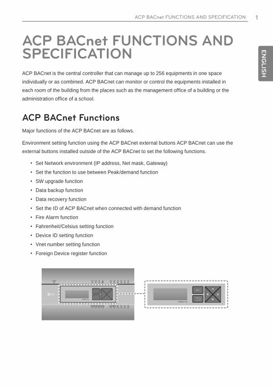
ACP BACnet FUNCTIONS AND SPECIFICATIONACP BACnet is the central controller that can manage up to 256 equipments in one space individually or as combined. ACP BACnet can monitor or control the equipments installed in each room of the building from the places such as the management office of a building or the administration office of a school.
ACP BACnet Functions
Major functions of the ACP BACnet are as follows.
Environment setting function using the ACP BACnet external buttons ACP BACnet can use the external buttons installed outside of the ACP BACnet to set the following functions.
Set Network environment (IP address, Net mask, Gateway)
Set the function to use between Peak/demand function
SW upgrade function
Data backup function
Data recovery function
Set the ID of ACP BACnet when connected with demand function
Fire Alarm function
Fahrenheit/Celsius setting function
Device ID setting function
Vnet number setting function
Foreign Device register function
PQNFB17C0
PQNFB17C0

2
EN
GLIS
H
ACP BACnet FUNCTIONS AND SPECIFICATION22
Embedded web server function
window using Internet Explorer, the central control program in ACP BACnet web server is automatically run, and the functions of various contents can be used.
Internet
Internet
Explorer
Controlling of up to 256 air conditioner indoor units
Monitoring of error and operation status
Controlling the peak power / demand power
System setting function
Devices that can interface with ACP BACnet
Device ACP BACnet
AC Ez o
Simple Central Controller o
AC-Smart o
AC Manager o
Air Conditioner o
Ventilation o
AWHP o
Fire Alarm o
Chiller x
AHU o
3E
NG
LIS
HACP BACnet FUNCTIONS AND SPECIFICATION 33
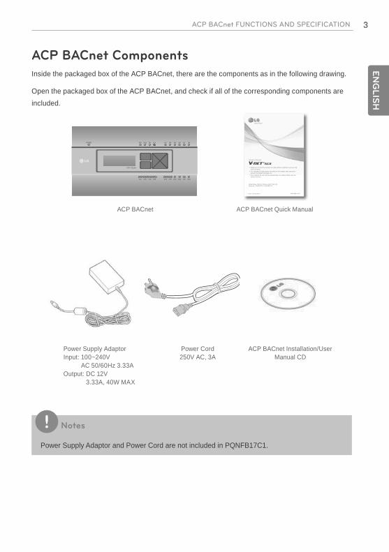
ACP BACnet Components
Inside the packaged box of the ACP BACnet, there are the components as in the following drawing.
Open the packaged box of the ACP BACnet, and check if all of the corresponding components are included.
ACP BACnet
Power Supply AdaptorInput: 100~240V
AC 50/60Hz 3.33AOutput: DC 12V
3.33A, 40W MAX
Power Cord250V AC, 3A
ACP BACnet Installation/User Manual CD
ACP BACnet Quick Manual
www.lge.comP/NO : MFL67709511
: BACnet Gateway (ACP BACnet)
: PQNFB17C1, PQNFB17C0
Make sure to read the cautions for safety before installation and use, and use it correctly.
It is intended to keep protect the safety of the installer and user and to prevent the property damage, etc.
After reading the user manual, please keep it at a place where user can access any time.
Quick manual
Notes
Power Supply Adaptor and Power Cord are not included in PQNFB17C1.
4
EN
GLIS
H
ACP BACnet FUNCTIONS AND SPECIFICATION
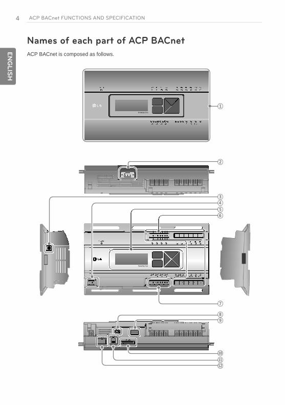
Names of each part of ACP BACnet
ACP BACnet is composed as follows.
PQNFB17C0
PQNFB17C0
PQNFB17C0
PQNFB17C0
5E
NG
LIS
HACP BACnet FUNCTIONS AND SPECIFICATION
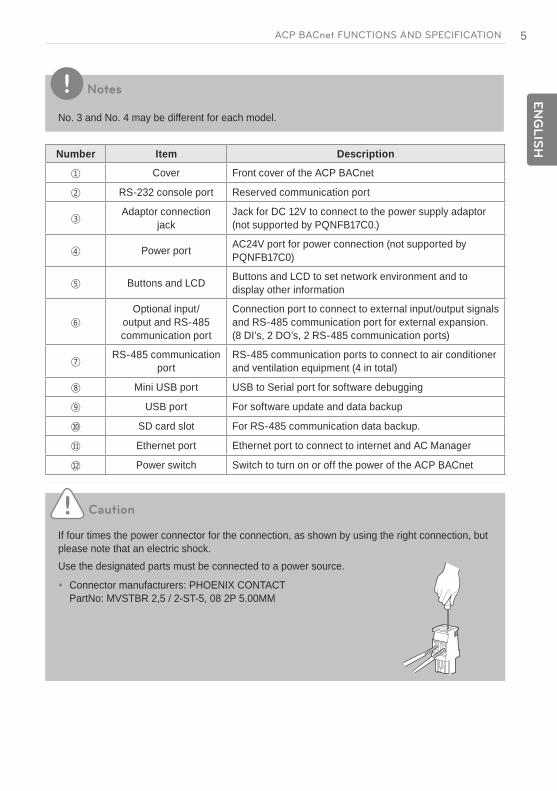
Notes
No. 3 and No. 4 may be different for each model.
Number Item Description
Cover Front cover of the ACP BACnet
RS-232 console port Reserved communication port
Adaptor connection jack
Jack for DC 12V to connect to the power supply adaptor (not supported by PQNFB17C0.)
Power port AC24V port for power connection (not supported by PQNFB17C0)
Buttons and LCD Buttons and LCD to set network environment and to display other information
Optional input/output and RS-485 communication port
Connection port to connect to external input/output signals and RS-485 communication port for external expansion. (8 DI’s, 2 DO’s, 2 RS-485 communication ports)
RS-485 communication port
RS-485 communication ports to connect to air conditioner and ventilation equipment (4 in total)
Mini USB port USB to Serial port for software debugging
USB port For software update and data backup
SD card slot For RS-485 communication data backup.
Ethernet port Ethernet port to connect to internet and AC Manager
Power switch Switch to turn on or off the power of the ACP BACnet
Caution
If four times the power connector for the connection, as shown by using the right connection, but please note that an electric shock.Use the designated parts must be connected to a power source.
Connector manufacturers: PHOENIX CONTACT PartNo: MVSTBR 2,5 / 2-ST-5, 08 2P 5.00MM
6
EN
GLIS
H
ACP BACnet FUNCTIONS AND SPECIFICATION
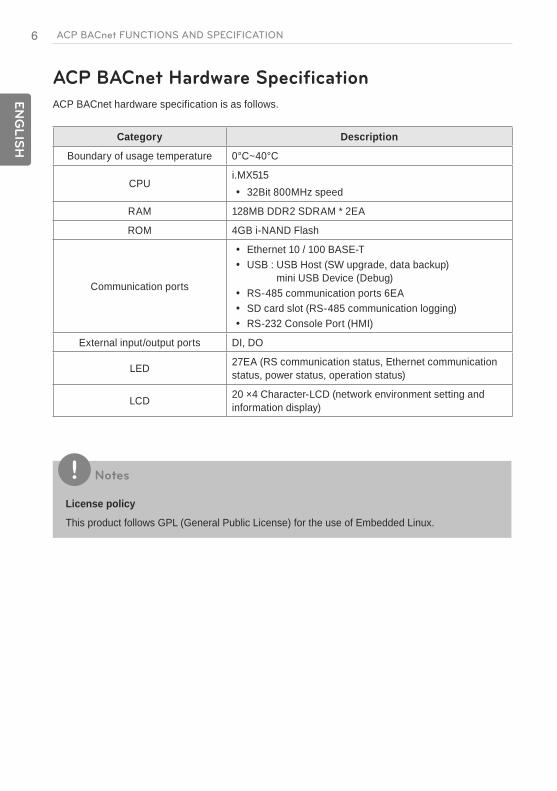
ACP BACnet Hardware Specification
ACP BACnet hardware specification is as follows.
Category Description
Boundary of usage temperature 0°C~40°C
CPUi.MX515
32Bit 800MHz speed
RAM 128MB DDR2 SDRAM * 2EA
ROM 4GB i-NAND Flash
Communication ports
Ethernet 10 / 100 BASE-T USB : USB Host (SW upgrade, data backup)
mini USB Device (Debug) RS-485 communication ports 6EA SD card slot (RS-485 communication logging) RS-232 Console Port (HMI)
External input/output ports DI, DO
LED 27EA (RS communication status, Ethernet communication status, power status, operation status)
LCD 20 ×4 Character-LCD (network environment setting and information display)
Notes
License policy
This product follows GPL (General Public License) for the use of Embedded Linux.
7E
NG
LIS
HStarting
Starting
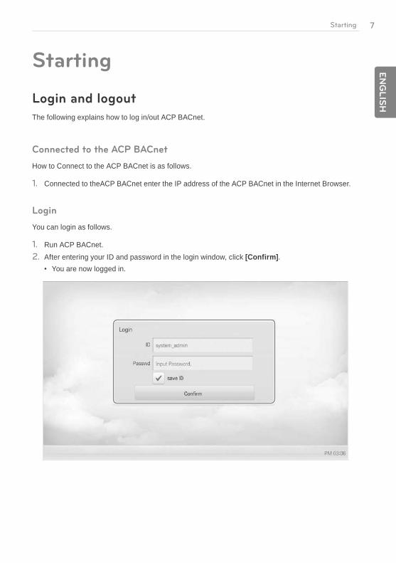
Login and logout
The following explains how to log in/out ACP BACnet.
Connected to the ACP BACnet
How to Connect to the ACP BACnet is as follows.
1. Connected to theACP BACnet enter the IP address of the ACP BACnet in the Internet Browser.
Login
You can login as follows.
1. Run ACP BACnet.2. After entering your ID and password in the login window, click [Confirm].
You are now logged in.

8
EN
GLIS
H
Starting
Logout
You can logout as follows.
1. On the top right of the ACP BACnet screen, click the [Logout] button.You are now logged out.

9E
NG
LIS
HStarting
Home screen composition and features
The following explains the home screen composition and features.
Number Item Description
Running Status (Unit)
Checks if all the devices are operating, has stopped, or has already been checked.
Time Check the current date and time. (You need Internet connection to check the weather.)
Today's Schedule Check the registered schedules in chronological order. Click the [+] button to move to the schedule menu.
Main Menu Use ACP BACnet main menu.
Home Return to the home screen.
View Menu Display the active menu.
Current Menu Display the name of the active menu.

EN
GLIS
H
MEMO

11E
NG
LIS
HUsing the Program
Using the ProgramThe following explains how to use the ACP BACnet functions.
Control/Monitor
Control/Monitoring is managing multiple devices collectively as one. The following explains the Control/Monitor menu options.
Control/Monitoring screen composition and features
The following explains Control/Monitoring screen composition and features.
Number Item Description
Select/Deselect All Select/deselect all devices in a group.
[Drawing] Button View floor plans of a group.
[Filter] Button Select device types for which you want to check the control status.
View TypeSelect
Select a view type for the monitoring screen (Icon/Simple/Detailed) (For more on View Type, refer to page 12)
Group List Check device group listings.

12
EN
GLIS
H
Using the Program
Number Item Description
Monitoring Screen Check the control status of a device.
Device Control Box
Display the device control menu. The device control box shows different menus
depending on the device. (For more on Control Menu per Device on page 17)
View Type
Control/Monitor menu has three types of views (icon, simple, and detailed). The following shows the screen composition and features per view type.
Icon
The control status is shown in icons. The device icon has a composition and feature as follows.
Number Item Description
Operation Mode and Device Status Icon
The color at the top of the icon box shows the current operation mode, and the status of the device is indicated as an icon.
Device IconThe device to be controlled is indicated as an icon.The device shown may not represent the appearance of the actual unit.
Current Temperature Display the current temperature.
Operation Mode Display the operation mode of the device.
Desired Temperature Display the desired temperature.
Device Name Display the name of the device.

13E
NG
LIS
HUsing the Program
Simple
The control device and operation mode are displayed only.
Number Item Description
Operation Mode The color of the box indicates the current operation mode.
Device Icon The device to be controlled is indicated as an icon.
Details
All properties of the control device are tabulated in details.
14
EN
GLIS
H
Using the Program
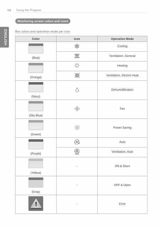
Monitoring screen colors and icons
Box colors and operation mode per icon
Color Icon Operation Mode
(Blue)
Cooling
Ventilation, General
(Orange)
Heating
Ventilation, Electric Heat
(Navy)
Dehumidification
(Sky Blue)
Fan
(Green)
Power Saving
(Purple)
Auto
Ventilation, Auto
(Yellow)
- ON & Short
(Gray)
- OFF & Open
- Error

15E
NG
LIS
HUsing the Program
Device status icon
Icon Device Status
Filter Exchange
Full Lock On
Peak/Demand Control
Schedule
Control device icon
Icon Device Type
Indoor Device
Ventilators
AHU
AWHP
Chiller
DI
DO
DOKIT

16
EN
GLIS
H
Using the Program
Device Control
You can control the devices as follows.
1. From the main menu, click the [Control/Monitor] menu icon.2. Click the device group you want to control from the group list.
The monitoring screen for the device is displayed.
3. Click the device you want to control.To select all devices, click the button at the top.
The device control area appears at the bottom of the screen.
4. In the device control box, set the control status of the device.The device control box shows a different menu depending on the device. For information about the control area for each device, GoTo the refer to Control Menu per Device on page 17.
5. Once you have finalized the settings, click the [Apply] button.

17E
NG
LIS
HUsing the Program
Control Menu per Device
The control box menu differs depending on the device. The following shows the control box menu per device.
Indoor Device
The following is the indoor unit control menu and features.
Item Description
Operation [ON] Button: Starts the operation of the device. [Off] Button: Stops the operation of the device.
GoTo [Schedule ] Button: Move to Schedule menu.
Room Display the current temperature.
Set TemperatureClick / to set the temperature.(The maximum/minimum temperatures that can be set may differ depending on the model.)
Mode
[COOL] Button: Operates with Cooling Mode. [HEAT] Button: Operates with Heating Mode. [AUTO] Button: Evaluates the operating environment conditions and
automatically sets the optimum temperature. [DRY] Button: Dehumidifies during rainy seasons or whenever humidity
is high. You cannot set the temperature in this mode. [FAN] Button: Purifies the air. You cannot set the temperature in this
mode.
Fan Speed
[LOW] Button: Slow fan speed. [MED] Button: Medium fan speed. [HIGH] Button: Fast fan speed. [AUTO] Button: Loops from LOW to MEDIUM to HIGH speeds.
Swing [Set] Button: Turns on automatic oscillation for the fan. [Clear] Button: Turns off automatic oscillation for the fan.
[Detail. ] Button Controls details.

18
EN
GLIS
H
Using the Program
Indoor unit fine control
Item Description
Operation [ON] Button: Starts the operation of the device. [Off] Button: Stops the operation of the device.
Set Click / to set the temperature.
Mode
[COOL] Button: Operates with Cooling Mode. [HEAT] Button: Operates with Heating Mode. [AUTO] Button: Evaluates the operating environment conditions and
automatically sets the optimum temperature. [DRY] Button: Dehumidifies during rainy seasons or whenever humidity is
high. You cannot set the temperature in this mode. [FAN] Button: Purifies the air. You cannot set the temperature in this
mode.
Fan Speed
[LOW] Button: Slow fan speed. [MED] Button: Medium fan speed. [HIGH] Button: Fast fan speed. [AUTO] Button: Loops from LOW to MEDIUM to HIGH speeds.
Swing [Set] Button: Turns on automatic oscillation of the fan. [Clear] Button: Turns off automatic oscillation of the fan.
Filter Alarm Click the Disable button to deactivate the filter exchange alarm. (For other models, it may not work properly.)

19E
NG
LIS
HUsing the Program
Item Description
Partial Lock
[HardLock] Button: Disables remote control for all features. [Clear] Button: All functions are unlocked. [ModeLock] Button: Disables remote control for local mode setting. [Clear] Button: Mode is unlocked. [FanLock] Button: Disables remote control for local fan speed setting. [Clear] Button: Fan speed is unlocked. [TempLock] Button: Disables remote control for local temperature setting. [Clear] Button: Temperature setting is unlocked.
Set Temp Range Click / to set the temperature limit.
[2Setpoint] Button Switches between cooling and heating within the selected temperature range.
Indoor 2Setpoint (Auto Operation Mode)
Item Description
Auto Change Over
(The auto change over function works well with "Heat Recovery" model. For other models, it may not work properly.)Set the auto change over function to switch the operation mode automatically to keep the proper room temperature.
[ON] Button: Enable Auto Change Over [OFF] Button: Disable Auto Change Over
Lower Click / to set the lower limit temperature range (16°C~30°C / 60°F~86°F).
Upper Click / to set the upper limit temperature range(16°C~30°C / 60°F~86°F).
20
EN
GLIS
H
Using the Program
Item Description
Setback
(The setback function works well with "Heat Recovery" model. For other models, it may not work properly.)Set the setback function to control the proper room temperature when the indoor unit is turned off.
[ON] Button: Enable temperature limits [OFF] Button: Disable temperature limits
Cooling Start Temp.
Click / to set the cooling start temperature(21°C~40°C / 70°F~104°F).
Heating Start Temp. Click / to set the heating start temperature (1°C~20°C / 34°F~68°F).
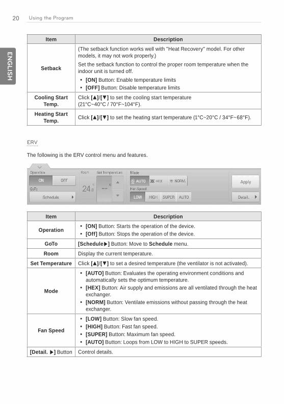
ERV
The following is the ERV control menu and features.
Item Description
Operation [ON] Button: Starts the operation of the device. [Off] Button: Stops the operation of the device.
GoTo [Schedule ] Button: Move to Schedule menu.
Room Display the current temperature.
Set Temperature Click / to set a desired temperature (the ventilator is not activated).
Mode
[AUTO] Button: Evaluates the operating environment conditions and automatically sets the optimum temperature.
[HEX] Button: Air supply and emissions are all ventilated through the heat exchanger.
[NORM] Button: Ventilate emissions without passing through the heat exchanger.
Fan Speed
[LOW] Button: Slow fan speed. [HIGH] Button: Fast fan speed. [SUPER] Button: Maximum fan speed. [AUTO] Button: Loops from LOW to HIGH to SUPER speeds.
[Detail. ] Button Control details.
21E
NG
LIS
HUsing the Program
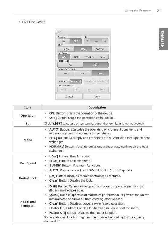
ERV Fine Control
Item Description
Operation [ON] Button: Starts the operation of the device. [OFF] Button: Stops the operation of the device.
Set Click / to set a desired temperature (the ventilator is not activated).
Mode
[AUTO] Button: Evaluates the operating environment conditions and automatically sets the optimum temperature.
[HEX] Button: Air supply and emissions are all ventilated through the heat exchanger.
[NORMAL] Button: Ventilate emissions without passing through the heat exchanger.
Fan Speed
[LOW] Button: Slow fan speed. [HIGH] Button: Fast fan speed. [SUPER] Button: Maximum fan speed. [AUTO] Button: Loops from LOW to HIGH to SUPER speeds.
Partial Lock [Set] Button: Disables remote control for all features. [Clear] Button: Disable the lock.
Additional Function
[Drift] Button: Reduces energy consumption by operating in the most efficient method possible.
[Quick] Button: Operates at maximum performance to prevent the room's contaminated or humid air from entering other spaces.
[Clear] Button: Disables power saving / rapid operation. [Heater On] Button: Enables the heater function to heat the room. [Heater Off] Button: Disables the heater function.
Some additional function might not be provided according to your country such as U.S.
22
EN
GLIS
H
Using the Program
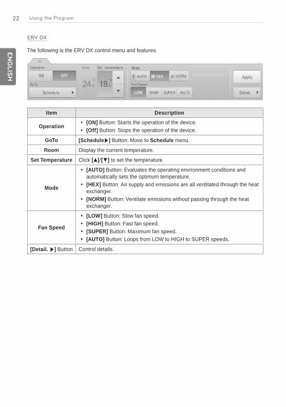
ERV DX
The following is the ERV DX control menu and features.
Item Description
Operation [ON] Button: Starts the operation of the device. [Off] Button: Stops the operation of the device.
GoTo [Schedule ] Button: Move to Schedule menu.
Room Display the current temperature.
Set Temperature Click / to set the temperature.
Mode
[AUTO] Button: Evaluates the operating environment conditions and automatically sets the optimum temperature.
[HEX] Button: Air supply and emissions are all ventilated through the heat exchanger.
[NORM] Button: Ventilate emissions without passing through the heat exchanger.
Fan Speed
[LOW] Button: Slow fan speed. [HIGH] Button: Fast fan speed. [SUPER] Button: Maximum fan speed. [AUTO] Button: Loops from LOW to HIGH to SUPER speeds.
[Detail. ] Button Control details.
23E
NG
LIS
HUsing the Program
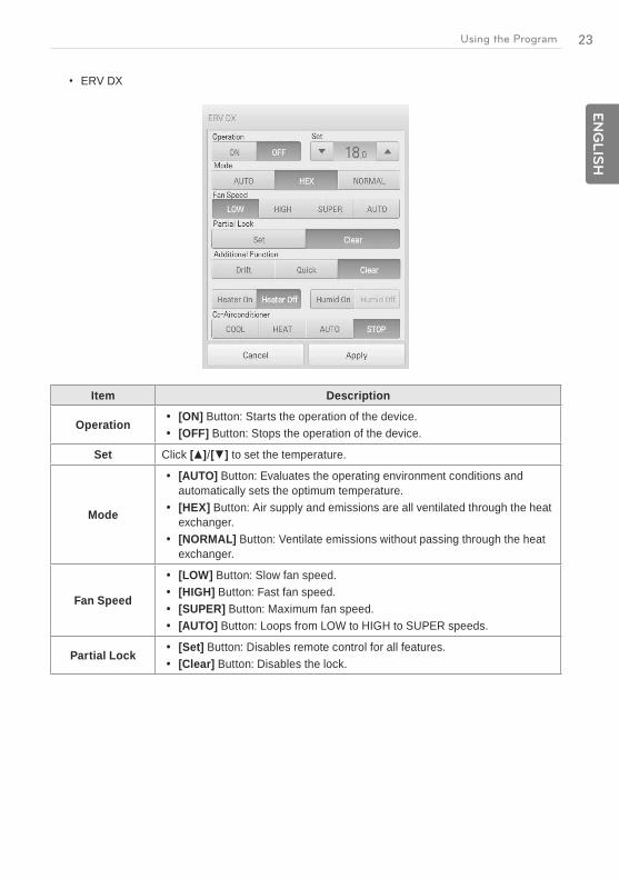
ERV DX
Item Description
Operation [ON] Button: Starts the operation of the device. [OFF] Button: Stops the operation of the device.
Set Click / to set the temperature.
Mode
[AUTO] Button: Evaluates the operating environment conditions and automatically sets the optimum temperature.
[HEX] Button: Air supply and emissions are all ventilated through the heat exchanger.
[NORMAL] Button: Ventilate emissions without passing through the heat exchanger.
Fan Speed
[LOW] Button: Slow fan speed. [HIGH] Button: Fast fan speed. [SUPER] Button: Maximum fan speed. [AUTO] Button: Loops from LOW to HIGH to SUPER speeds.
Partial Lock [Set] Button: Disables remote control for all features. [Clear] Button: Disables the lock.
24
EN
GLIS
H
Using the Program
Item Description
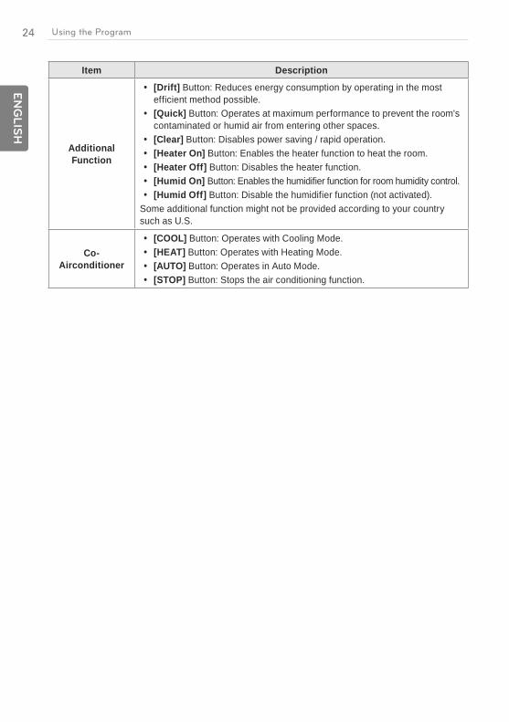
Additional Function
[Drift] Button: Reduces energy consumption by operating in the most efficient method possible.
[Quick] Button: Operates at maximum performance to prevent the room's contaminated or humid air from entering other spaces.
[Clear] Button: Disables power saving / rapid operation. [Heater On] Button: Enables the heater function to heat the room. [Heater Off] Button: Disables the heater function. [Humid On] Button: Enables the humidifier function for room humidity control. [Humid Off] Button: Disable the humidifier function (not activated).
Some additional function might not be provided according to your country such as U.S.
Co- Airconditioner
[COOL] Button: Operates with Cooling Mode. [HEAT] Button: Operates with Heating Mode. [AUTO] Button: Operates in Auto Mode. [STOP] Button: Stops the air conditioning function.
25E
NG
LIS
HUsing the Program
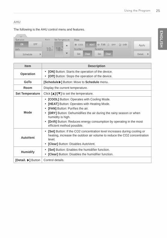
AHU
The following is the AHU control menu and features.
Item Description
Operation [ON] Button: Starts the operation of the device. [Off] Button: Stops the operation of the device.
GoTo [Schedule ] Button: Move to Schedule menu.
Room Display the current temperature.
Set Temperature Click / to set the temperature.
Mode
[COOL] Button: Operates with Cooling Mode. [HEAT] Button: Operates with Heating Mode. [FAN] Button: Purifies the air. [DRY] Button: Dehumidifies the air during the rainy season or when
humidity is high. [Drift] Button: Reduces energy consumption by operating in the most
efficient method possible.
AutoVent
[Set] Button: If the CO2 concentration level increases during cooling or heating, increase the outdoor air volume to reduce the CO2 concentration level.
[Clear] Button: Disables AutoVent.
Humidify [Set] Button: Enables the humidifier function. [Clear] Button: Disables the humidifier function.
[Detail. ] Button Control details.
26
EN
GLIS
H
Using the Program
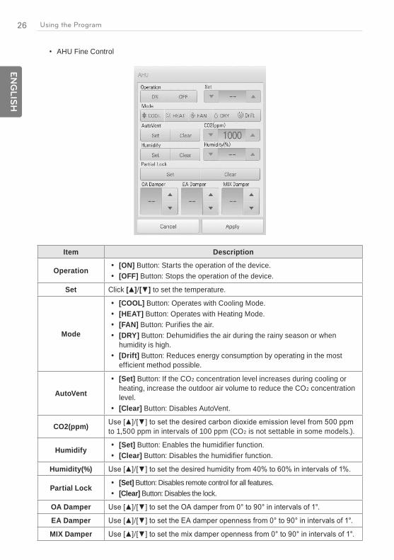
AHU Fine Control
Item Description
Operation [ON] Button: Starts the operation of the device. [OFF] Button: Stops the operation of the device.
Set Click / to set the temperature.
Mode
[COOL] Button: Operates with Cooling Mode. [HEAT] Button: Operates with Heating Mode. [FAN] Button: Purifies the air. [DRY] Button: Dehumidifies the air during the rainy season or when
humidity is high. [Drift] Button: Reduces energy consumption by operating in the most
efficient method possible.
AutoVent
[Set] Button: If the CO concentration level increases during cooling or heating, increase the outdoor air volume to reduce the CO concentration level.
[Clear] Button: Disables AutoVent.
CO2(ppm) to 1,500 ppm in intervals of 100 ppm (CO is not settable in some models.).
Humidify [Set] Button: Enables the humidifier function. [Clear] Button: Disables the humidifier function.
Humidity(%)
Partial Lock [Set] Button: Disables remote control for all features. [Clear] Button: Disables the lock.
OA Damper
EA Damper
MIX Damper

27E
NG
LIS
HUsing the Program
DOKIT
The following is the DOKIT control menu and features.
Item Description
Operation [ON] Button: Starts the operation of the device. [Off] Button: Stops the operation of the device.
GoTo [Schedule ] Button: Move to Schedule menu.
AWHP
The following is the AWHP control menu and features.
Item Description
Operation [ON] Button: Starts the operation of the device. [Off] Button: Stops the operation of the device.
GoTo [Schedule ] Button: Move to Schedule menu.
Mode
[AUTO] Button: Evaluates the operating environment conditions and automatically sets the optimum temperature.
[COOL] Button: Operates with Cooling Mode. [HEAT] Button: Operates with Heating Mode.
Air/Water Temp. (Indicated as air or water temperature depending on the product.)Click / to set the air/water temperature.
HotWater Temp. Click / to set the water heater temperature.
[Detail. ] Button Control details.
28
EN
GLIS
H
Using the Program
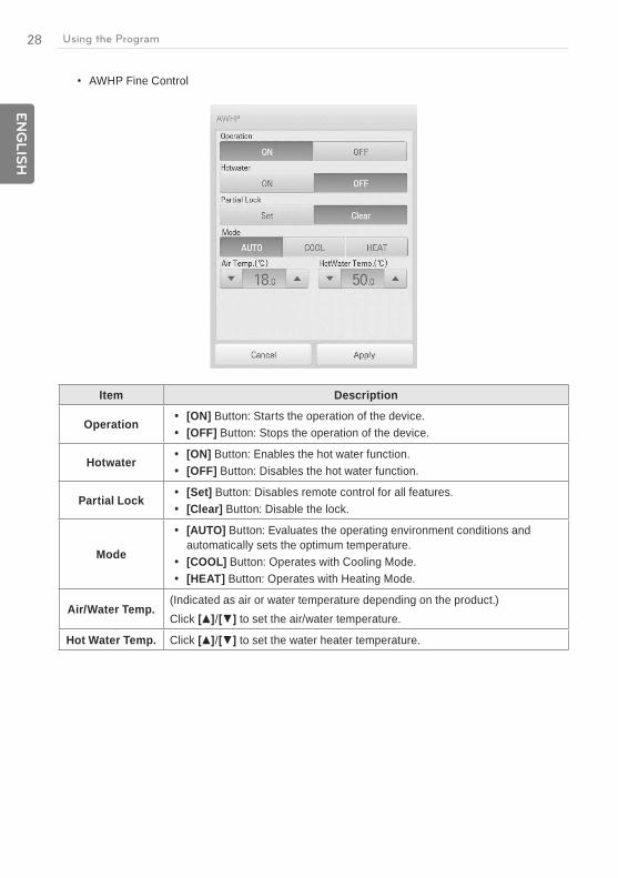
AWHP Fine Control
Item Description
Operation [ON] Button: Starts the operation of the device. [OFF] Button: Stops the operation of the device.
Hotwater [ON] Button: Enables the hot water function. [OFF] Button: Disables the hot water function.
Partial Lock [Set] Button: Disables remote control for all features. [Clear] Button: Disable the lock.
Mode
[AUTO] Button: Evaluates the operating environment conditions and automatically sets the optimum temperature.
[COOL] Button: Operates with Cooling Mode. [HEAT] Button: Operates with Heating Mode.
Air/Water Temp. (Indicated as air or water temperature depending on the product.)Click / to set the air/water temperature.
Hot Water Temp. Click / to set the water heater temperature.

29E
NG
LIS
HUsing the Program
DO
The following is the DO control menu and features.
Item Description
Operation [SHORT] Button: Short signal output. [OPEN] Button: Open signal output.
GoTo [Schedule ] Button: Move to Schedule menu.

30
EN
GLIS
H
Using the Program
Registering Floor Plan
In the Control/Monitor menu, you can register floor plans to identify and locate each device and device group. On the floor plan, you can register space information as well as the location where a device is installed.
1. In the main menu, click the [Control/Monitor] menu icon.2. Select the device group you want to monitor from the group list.
The monitoring screen for the device is displayed.
3. Click [Drawing] button.
4. Click [Edit] button.
31E
NG
LIS
HUsing the Program
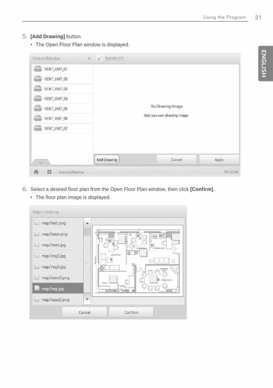
5. [Add Drawing] button.The Open Floor Plan window is displayed.
6. Select a desired floor plan from the Open Floor Plan window, then click [Confirm].The floor plan image is displayed.
32
EN
GLIS
H
Using the Program
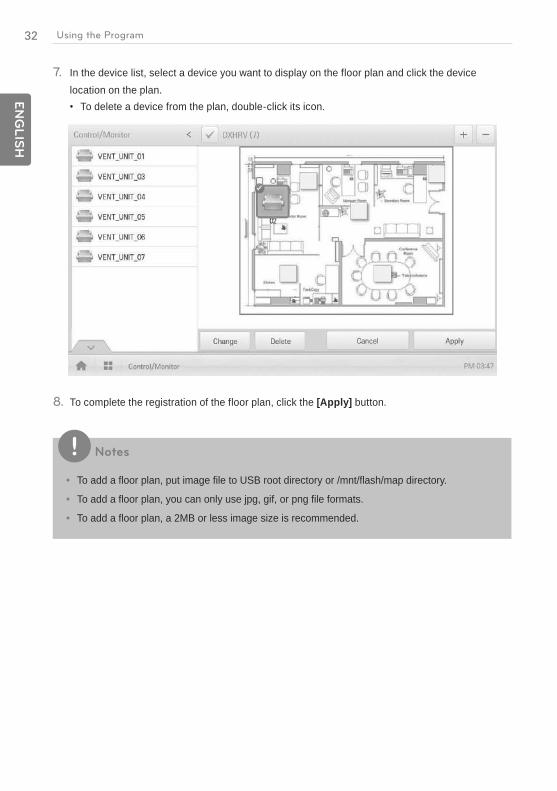
7. In the device list, select a device you want to display on the floor plan and click the device location on the plan.
To delete a device from the plan, double-click its icon.
8. To complete the registration of the floor plan, click the [Apply] button.
Notes
To add a floor plan, put image file to USB root directory or /mnt/flash/map directory.
To add a floor plan, you can only use jpg, gif, or png file formats.
To add a floor plan, a 2MB or less image size is recommended.
33E
NG
LIS
HUsing the Program
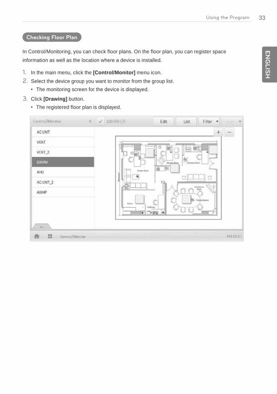
Checking Floor Plan
In Control/Monitoring, you can check floor plans. On the floor plan, you can register space information as well as the location where a device is installed.
1. In the main menu, click the [Control/Monitor] menu icon.2. Select the device group you want to monitor from the group list.
The monitoring screen for the device is displayed.
3. Click [Drawing] button.The registered floor plan is displayed.
34
EN
GLIS
H
Using the Program
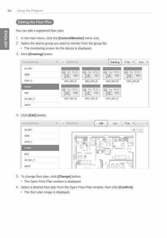
Editing the Floor Plan
You can edit a registered floor plan.
1. In the main menu, click the [Control/Monitor] menu icon.2. Select the device group you want to monitor from the group list.
The monitoring screen for the device is displayed.
3. Click [Drawing] button.
4. Click [Edit] button.
5. To change floor plan, click [Change] button.The Open Floor Plan window is displayed.
6. Select a desired floor plan from the Open Floor Plan window, then click [Confirm].The floor plan image is displayed.

35E
NG
LIS
HUsing the Program
7. To change the location of a device, click the icon of the device and then click the location to which you want to move that device.
8. To complete floor plan editing, click the [Apply] button.
Notes
To add a floor plan, put image file to USB root directory or /mnt/flash/map directory.
To add a floor plan, you can only use jpg, gif, or png file formats.
To add a floor plan, a 2MB or less image size is recommended.
36
EN
GLIS
H
Using the Program
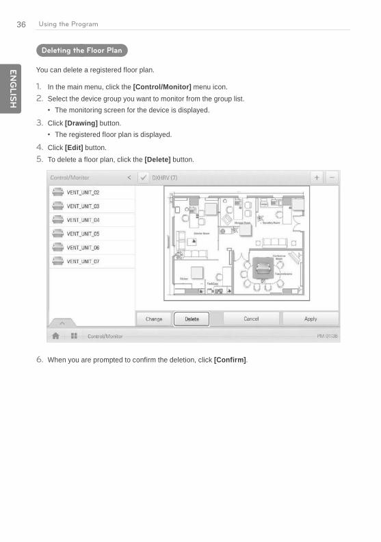
Deleting the Floor Plan
You can delete a registered floor plan.
1. In the main menu, click the [Control/Monitor] menu icon.2. Select the device group you want to monitor from the group list.
The monitoring screen for the device is displayed.
3. Click [Drawing] button.The registered floor plan is displayed.
4. Click [Edit] button.5. To delete a floor plan, click the [Delete] button.
6. When you are prompted to confirm the deletion, click [Confirm].
37E
NG
LIS
HUsing the Program
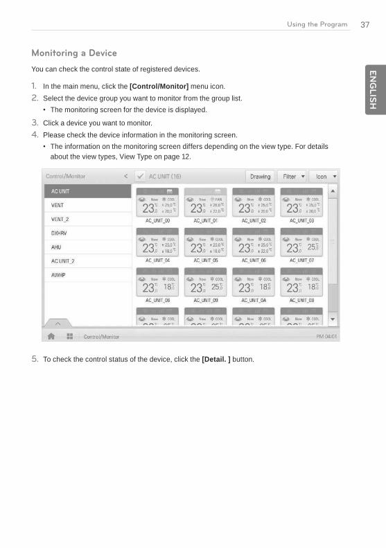
Monitoring a Device
You can check the control state of registered devices.
1. In the main menu, click the [Control/Monitor] menu icon.2. Select the device group you want to monitor from the group list.
The monitoring screen for the device is displayed.
3. Click a device you want to monitor.4. Please check the device information in the monitoring screen.
The information on the monitoring screen differs depending on the view type. For details about the view types, View Type on page 12.
5. To check the control status of the device, click the [Detail. ] button.
38
EN
GLIS
H
Using the Program
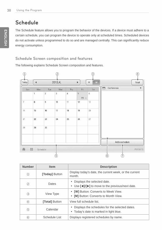
Schedule
The Schedule feature allows you to program the behavior of the devices. If a device must adhere to a certain schedule, you can program the device to operate only at scheduled times. Scheduled devices do not activate unless programmed to do so and are managed centrally. This can significantly reduce energy consumption.
Schedule Screen composition and features
The following explains Schedule Screen composition and features.
Number Item Description
[Today] Button Display today's date, the current week, or the current month.
Dates Displays the selected date. Use [ ]/[ ] to move to the previous/next date.
View Type [W] Button: Converts to Week View. [M] Button: Converts to Month View.
[Total] Button View full schedule list.
Calendar Displays the schedules for the selected dates. Today's date is marked in light blue.
Schedule List Displays registered schedules by name.
39E
NG
LIS
HUsing the Program
Number Item Description
[Add a Schedule]Button
Registers new schedules.
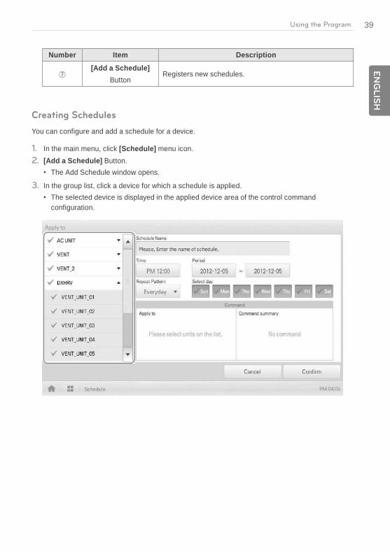
Creating Schedules
You can configure and add a schedule for a device.
1. In the main menu, click [Schedule] menu icon.2. [Add a Schedule] Button.
The Add Schedule window opens.
3. In the group list, click a device for which a schedule is applied.The selected device is displayed in the applied device area of the control command configuration.

40
EN
GLIS
H
Using the Program
4. Configure the schedule information that controls the device.
Item Description
Schedule Name Click the input box. Enter the name of the schedule..
Time Click the time area and then the [+]/[-] button to select the desired
time. Click the [AM]/[PM] button to select before or after midday.
Period Click the period area and then the [+]/[-] button to select the desired period.
Repeat Pattern
Click the Repetition Pattern area and select a desired pattern. Select Day: Selected days the schedule will be performed. Once: Applies a schedule once on a selected date. Everyday: Applies the same schedule Everyday. Mon - Fri: Applies a schedule repeatedly from Monday to Friday. Mon - Sat: Applies a schedule repeatedly from Monday to
Saturday.
Select day Click a desired day to apply a schedule.
41E
NG
LIS
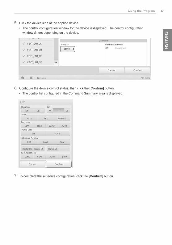
HUsing the Program
5. Click the device icon of the applied device.The control configuration window for the device is displayed. The control configuration window differs depending on the device.
6. Configure the device control status, then click the [Confirm] button.The control list configured in the Command Summary area is displayed.
7. To complete the schedule configuration, click the [Confirm] button.
42
EN
GLIS
H
Using the Program
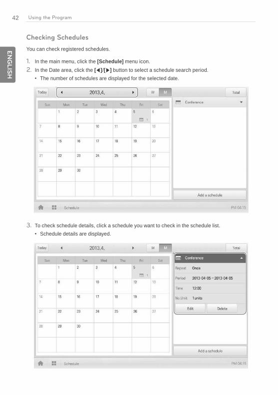
Checking Schedules
You can check registered schedules.
1. In the main menu, click the [Schedule] menu icon.2. In the Date area, click the [ ]/[ ] button to select a schedule search period.
The number of schedules are displayed for the selected date.
3. To check schedule details, click a schedule you want to check in the schedule list.Schedule details are displayed.

43E
NG
LIS
HUsing the Program
Editing Schedules
You can modify the content of a registered schedule as follows.
1. In the main menu, click the [Schedule] menu icon.2. Click a schedule you wish to modify from the schedule list.
Schedule details are displayed.
3. Click the [Edit] button.The schedule configuration screen is displayed.
4. Modify the schedule information and device control configuration, then click the [Confirm] button.
The changed data will be saved.
44
EN
GLIS
H
Using the Program
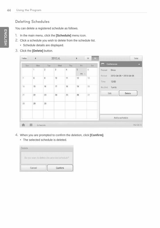
Deleting Schedules
You can delete a registered schedule as follows.
1. In the main menu, click the [Schedule] menu icon.2. Click a schedule you wish to delete from the schedule list.
Schedule details are displayed.
3. Click the [Delete] button.
4. When you are prompted to confirm the deletion, click [Confirm].The selected schedule is deleted.
45E
NG
LIS
HUsing the Program
Auto Logic
Auto Logic allows the system to automatically control the power consumption of external devices. You can also set the indoor temperature to automatically adjust to outdoor conditions or activate devices for certain periods of time.
Notes
If you set a device control value in the auto logic status view, the device can operate based on that value.
Peak Control
Peak control limits peak power consumption. You can set the target operating rate so that total power consumption does not exceed the set limit. To prevent power consumption from exceeding the limit, the system will automatically change cooling mode to fan mode and cancel heating mode.
Notes
Depending on the installation site specifications, either of the peak control and demand control functions can be selected. Go to Environment > Advance Setting > Peak/Demand Set and select a desired control type.
46
EN
GLIS
H
Using the Program
Editing Groups
The auto logic designates the registered devices as a group and controls them by group. The following explains how to create groups and how to edit the created groups.
Adding Groups
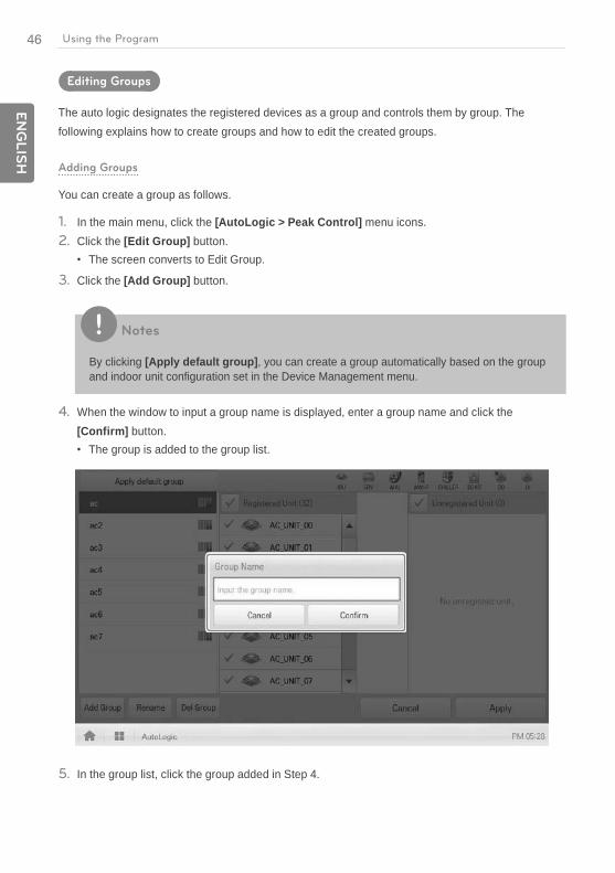
You can create a group as follows.
1. In the main menu, click the [AutoLogic > Peak Control] menu icons.2. Click the [Edit Group] button.
The screen converts to Edit Group.
3. Click the [Add Group] button.
Notes
By clicking [Apply default group], you can create a group automatically based on the group and indoor unit configuration set in the Device Management menu.
4. When the window to input a group name is displayed, enter a group name and click the [Confirm] button.
The group is added to the group list.
5. In the group list, click the group added in Step 4.
47E
NG
LIS
HUsing the Program
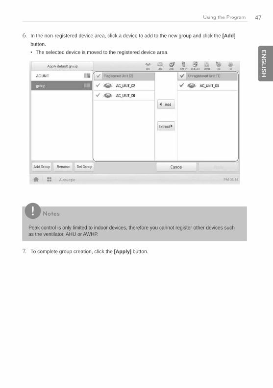
6. In the non-registered device area, click a device to add to the new group and click the [Add] button.
The selected device is moved to the registered device area.
Notes
Peak control is only limited to indoor devices, therefore you cannot register other devices such as the ventilator, AHU or AWHP.
7. To complete group creation, click the [Apply] button.

48
EN
GLIS
H
Using the Program
Changing Group Name
You can change the name of a registered group as follows.
1. In the main menu, click the [AutoLogic > Peak Control] menu icon.2. Click the [Edit Group] button.
The screen converts to Edit Group.
3. In the group list, click a group whose name you want to change and click the [Rename] button.
4. Enter a new group name and click the [Confirm] button.The group name is now changed.
49E
NG
LIS
HUsing the Program
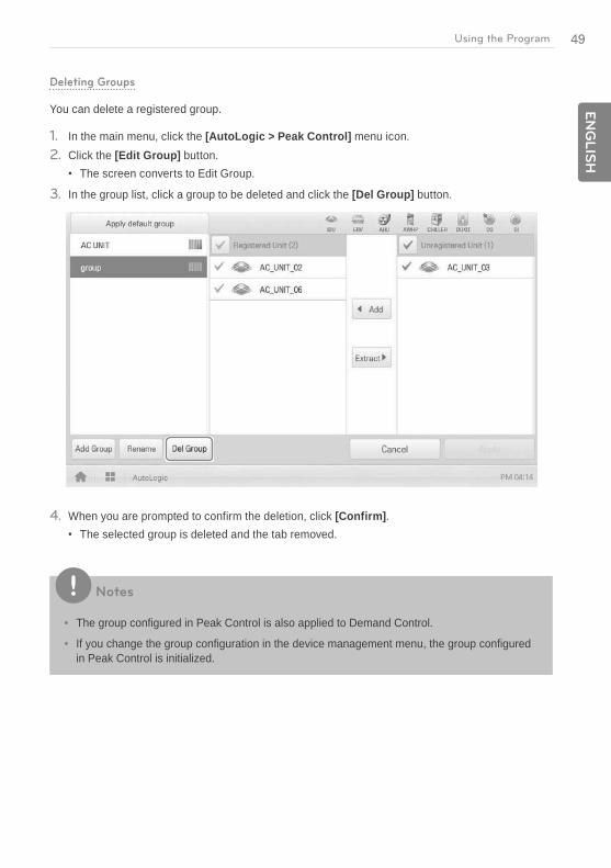
Deleting Groups
You can delete a registered group.
1. In the main menu, click the [AutoLogic > Peak Control] menu icon.2. Click the [Edit Group] button.
The screen converts to Edit Group.
3. In the group list, click a group to be deleted and click the [Del Group] button.
4. When you are prompted to confirm the deletion, click [Confirm].The selected group is deleted and the tab removed.
Notes
The group configured in Peak Control is also applied to Demand Control.
If you change the group configuration in the device management menu, the group configured in Peak Control is initialized.
50
EN
GLIS
H
Using the Program
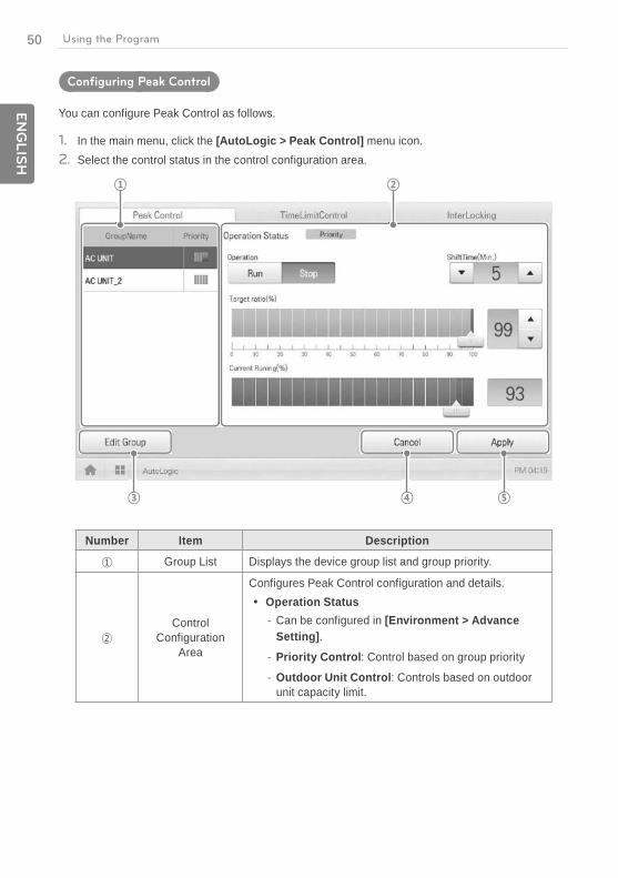
Configuring Peak Control
You can configure Peak Control as follows.
1. In the main menu, click the [AutoLogic > Peak Control] menu icon.2. Select the control status in the control configuration area.
Number Item Description
Group List Displays the device group list and group priority.
Control Configuration
Area
Configures Peak Control configuration and details. Operation Status
- Can be configured in [Environment > Advance Setting].
- Priority Control: Control based on group priority
- Outdoor Unit Control: Controls based on outdoor unit capacity limit.

51E
NG
LIS
HUsing the Program
Number Item Description
Control Configuration
Area
(Operation Status - Priority Control selected) Operation
- [Run] Button: Operates the device.
- [Stop] Button: Stops the operation of the device. Shift Time(Min.): Click / to set the time in
minutes to force the operation to switch over. Target ratio(%): Click / or drag to set the target
rate. Current Running(%): Displays the current rate.
(Operation Status - Outdoor unit capacity control selected) Operation
- [Run] Button: Operates the device.
- [Stop] Button: Stops the operation of the device. Target ratio(%): Click / or drag to set the target
rate.
[Edit Group] Button Edit a control group.
[Cancel] Button Cancels control configuration.
[Apply] Button Applies control configuration.
3. To complete configuration, click the [Apply] button.
52
EN
GLIS
H
Using the Program
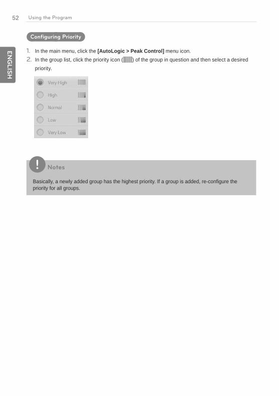
Configuring Priority
1. In the main menu, click the [AutoLogic > Peak Control] menu icon.2. In the group list, click the priority icon ( ) of the group in question and then select a desired
priority.
Notes
Basically, a newly added group has the highest priority. If a group is added, re-configure the priority for all groups.

53E
NG
LIS
HUsing the Program
Checking Peak Control Status
You can check the Peak Control configuration status as follows.
1. In the main menu, click the [AutoLogic > Peak Control] menu icon.2. Check how Peak Control is configured.
54
EN
GLIS
H
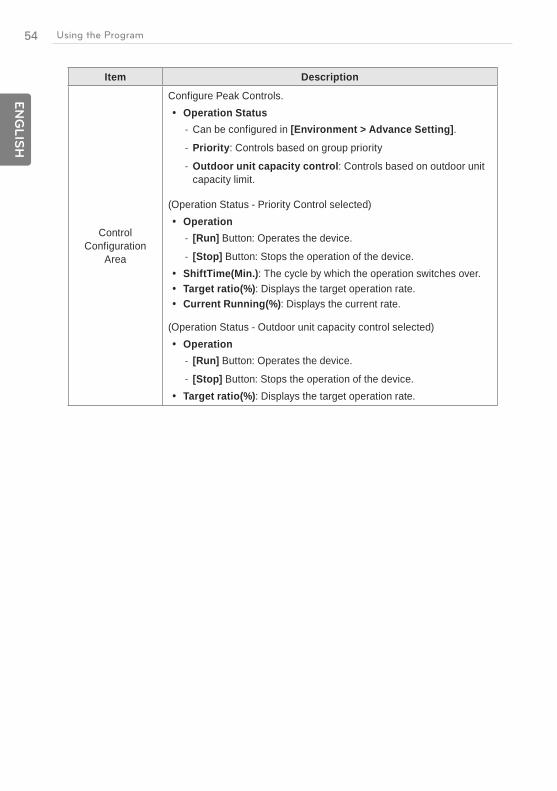
Using the Program
Item Description
Control Configuration
Area
Configure Peak Controls. Operation Status
- Can be configured in [Environment > Advance Setting]. - Priority: Controls based on group priority
- Outdoor unit capacity control: Controls based on outdoor unit capacity limit.
(Operation Status - Priority Control selected) Operation
- [Run] Button: Operates the device.
- [Stop] Button: Stops the operation of the device. ShiftTime(Min.): The cycle by which the operation switches over. Target ratio(%): Displays the target operation rate. Current Running(%): Displays the current rate.
(Operation Status - Outdoor unit capacity control selected) Operation
- [Run] Button: Operates the device.
- [Stop] Button: Stops the operation of the device. Target ratio(%): Displays the target operation rate.

55E
NG
LIS
HUsing the Program
Checking Demand Control Status
You can check the Peak Control configuration status as follows.
1. In the main menu, click the [AutoLogic > Demand Control] menu icon.2. Check how Demand Control is configured.
Number Item Description
Comm. Status with Demand
Controller
Displays the communication status between demand controller and ACP BACnet.
Control Configuration
Area
Checks the demand configuration details. Operation Status
- Can be configured in [Environment > Advance Setting].
- Priority Control: Control based on group priority
- Outdoor Unit Control: Controls based on outdoor unit capacity limit.

56
EN
GLIS
H
Using the Program
Number Item Description
Control Configuration
Area
(Operation Status - Priority Control selected) Operation
- [Operate] Button: Operates the device.
- [Stop] Button: Stops the operation of the device. Shift Time(Min.): The cycle by which the operation
switches over. Target ratio(%): Displays the target operation rate. Current Running(%): Displays the current rate.
(Operation Status - Outdoor unit capacity control selected) Operation
- [Run] Button: Operates the device.
- [Stop] Button: Stops the operation of the device. Target ratio(%): Displays the target operation rate.
57E
NG
LIS
HUsing the Program
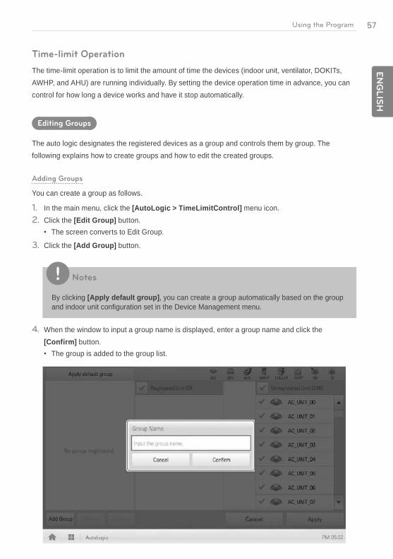
Time-limit Operation
The time-limit operation is to limit the amount of time the devices (indoor unit, ventilator, DOKITs, AWHP, and AHU) are running individually. By setting the device operation time in advance, you can control for how long a device works and have it stop automatically.
Editing Groups
The auto logic designates the registered devices as a group and controls them by group. The following explains how to create groups and how to edit the created groups.
Adding Groups
You can create a group as follows.
1. In the main menu, click the [AutoLogic > TimeLimitControl] menu icon.2. Click the [Edit Group] button.
The screen converts to Edit Group.
3. Click the [Add Group] button.
Notes
By clicking [Apply default group], you can create a group automatically based on the group and indoor unit configuration set in the Device Management menu.
4. When the window to input a group name is displayed, enter a group name and click the [Confirm] button.
The group is added to the group list.

58
EN
GLIS
H
Using the Program
5. In the group list, click the group added in Step 4.6. In the non-registered device area, click a device to add to the new group and click [Add] button.
The selected device is moved to the registered device area.
Notes
For the time-limit operation, you cannot register DI/DO.
7. To complete group creation, click the [Apply] button.
59E
NG
LIS
HUsing the Program
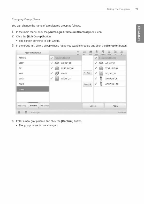
Changing Group Name
You can change the name of a registered group as follows.
1. In the main menu, click the [AutoLogic > TimeLimitControl] menu icon.2. Click the [Edit Group] button.
The screen converts to Edit Group.
3. In the group list, click a group whose name you want to change and click the [Rename] button.
4. Enter a new group name and click the [Confirm] button.The group name is now changed.
60
EN
GLIS
H
Using the Program
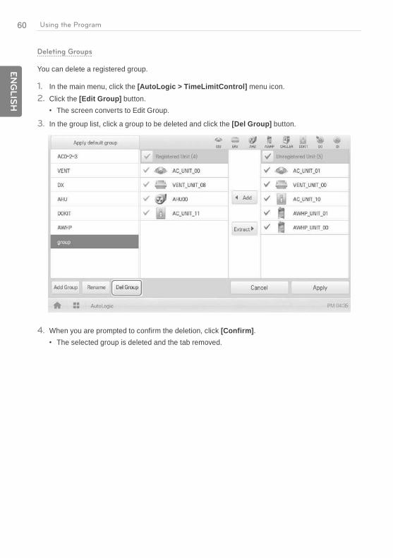
Deleting Groups
You can delete a registered group.
1. In the main menu, click the [AutoLogic > TimeLimitControl] menu icon.2. Click the [Edit Group] button.
The screen converts to Edit Group.
3. In the group list, click a group to be deleted and click the [Del Group] button.
4. When you are prompted to confirm the deletion, click [Confirm].The selected group is deleted and the tab removed.
61E
NG
LIS
HUsing the Program
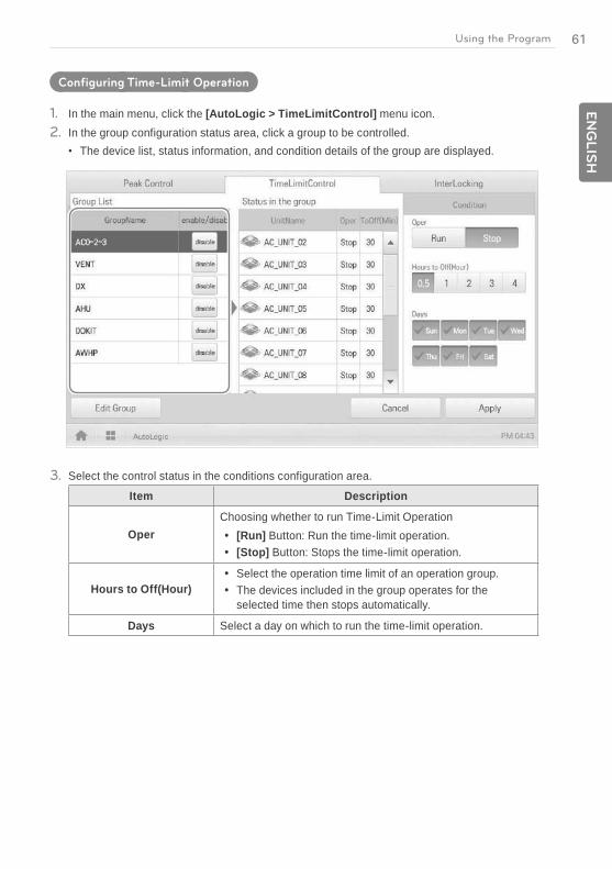
Configuring Time-Limit Operation
1. In the main menu, click the [AutoLogic > TimeLimitControl] menu icon.2. In the group configuration status area, click a group to be controlled.
The device list, status information, and condition details of the group are displayed.
3. Select the control status in the conditions configuration area.
Item Description
OperChoosing whether to run Time-Limit Operation
[Run] Button: Run the time-limit operation. [Stop] Button: Stops the time-limit operation.
Hours to Off(Hour) Select the operation time limit of an operation group. The devices included in the group operates for the
selected time then stops automatically.
Days Select a day on which to run the time-limit operation.
62
EN
GLIS
H
Using the Program
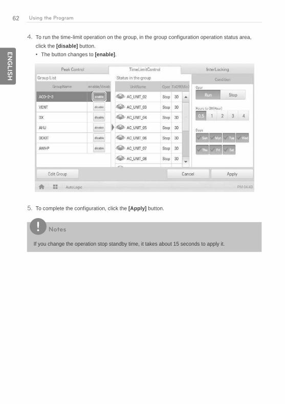
4. To run the time-limit operation on the group, in the group configuration operation status area, click the [disable] button.
The button changes to [enable].
5. To complete the configuration, click the [Apply] button.
Notes
If you change the operation stop standby time, it takes about 15 seconds to apply it.

63E
NG
LIS
HUsing the Program
InterLocking
You can integrate the system with external devices, like fire alarms, to halt the operation of all indoor units and ventilators. For InterLocking, you should create a pattern for devices and apply the control configuration. The following explains how to create and manage a pattern and control device integration.
Managing Pattern
The following explains how to register integrated devices as a pattern and how to modify or delete a registered pattern.
Adding Pattern
You can add a pattern as follows.
1. In the main menu, click the [AutoLogic > InterLocking] menu icon.2. Click the [Add] button.
A window to create a pattern is displayed.
3. Type a new pattern name in the pattern name input window.
4. Click the [Input Device] tab.

64
EN
GLIS
H
Using the Program
5. In the non-registered device area, click a device to be registered and click the [Add] button.
6. In the input device list, click the device you want to control.7. Select a control status in the control configuration area.8. Click the [Output Device] tab.9. In the non-registered device area, click a device to be registered and click the [Add] button.
10. In the output device list, click the device you want to control.11. Select a control status in the control configuration area.12. To complete the adding of a pattern, click the [Apply] button.
65E
NG
LIS
HUsing the Program
Editing Pattern
You can edit a pattern as follows.
1. In the main menu, click the [AutoLogic > InterLocking] menu icon.2. Select a pattern and click the [Edit] button.
The pattern editing screen opens.
3. Modify the pattern configuration information and click the [Apply] button.
Deleting Pattern
You can delete a pattern as follows.
1. In the main menu, click the [AutoLogic > InterLocking] menu icon.2. Select a pattern to be deleted and click the [Delete] button.3. When you are prompted to confirm the deletion, click [OK].
The selected pattern is deleted.
66
EN
GLIS
H
Using the Program
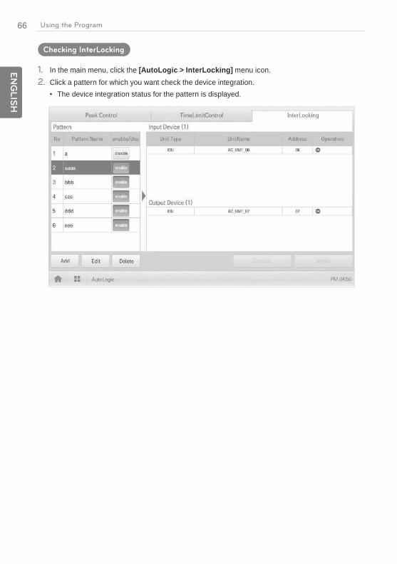
Checking InterLocking
1. In the main menu, click the [AutoLogic > InterLocking] menu icon.2. Click a pattern for which you want check the device integration.
The device integration status for the pattern is displayed.
67E
NG
LIS
HUsing the Program
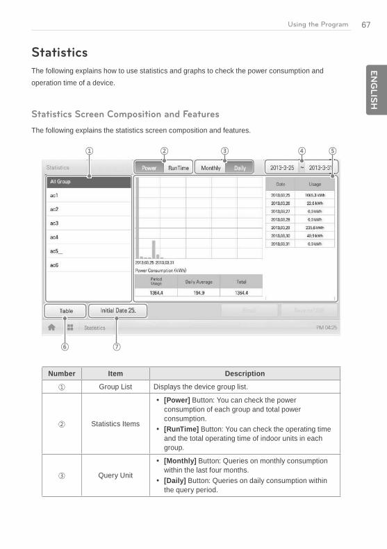
Statistics
The following explains how to use statistics and graphs to check the power consumption and operation time of a device.
Statistics Screen Composition and Features
The following explains the statistics screen composition and features.
Number Item Description
Group List Displays the device group list.
Statistics Items
[Power] Button: You can check the power consumption of each group and total power consumption.
[RunTime] Button: You can check the operating time and the total operating time of indoor units in each group.
Query Unit
[Monthly] Button: Queries on monthly consumption within the last four months.
[Daily] Button: Queries on daily consumption within the query period.

68
EN
GLIS
H
Using the Program
Number Item Description
Query Period Selection Area
Selects the period for which you want to query statistics details for daily.
The start date should be no more than 31days before the end date.
Displays Statistics Information
Statistics data per period: Displays power consumption per unit of query or operation time statistics and graphs.
Power consumption: Displays power consumption and use time.
[Table]/[Graph] Button
Converting Statistics Data View Table: Views the queried statistics data in a table
format. Graph: Views the queried statistics data in a graphic
format.
[Initial Date] Button
Selects Statistics Reference Date. Move to Settings > General Settings > Statistics
Reference Date.
Querying Statistics
You can query the power consumption of a device or operation time statistics data as follows.
1. In the main menu, click the [Statistics] menu icon.2. Click the device group you want from the group list.3. Click the button of the statistics item you want.
[Power] Button: You can check the power consumption of each group and total power consumption.
[RunTime] Button: You can check the operating time and the total operating time of indoor units in each group.
4. In the query period selection area, click the date button and [+]/[-] button to select the desired period.
The start date should be no more than 31days for daily before the end date. The query period for monthly is automatically fixed to the last four months.

69E
NG
LIS
HUsing the Program
5. Check the statistics details in the statistics information display area.To change the statistics information view type, click the [Table] or [Graphic] button.
Notes
The statistics data is stored up to 6 months.
Notes
Devices which can query the Run Time: Indoor units
Devices which can query the Power consumption: devices which can be used with the PDI (For further information about the devices can be used with the PDI, please refer to the PDI manual.)

70
EN
GLIS
H
Using the Program
Report
The following explains how to query the device control information or error information.
Report screen composition and features
The following explains the report screen composition and features.
Number Item Description
Report Items
Selects report query items. [Total] Button: Queries all reports regarding control
and error. [Control] Button: Queries control related reports
only. [Error] Button: Queries error related reports only.
Query Period Selection Area
Selects the period for which you want to query report details.
The starting date should be no more than three months from the ending date.
Report detail display area Displays the reports related to control and error.
[Delete Report]Button Deletes the selected report.
71E
NG
LIS
HUsing the Program
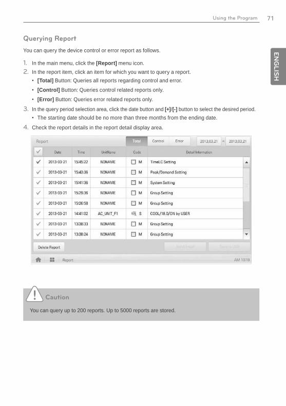
Querying Report
You can query the device control or error report as follows.
1. In the main menu, click the [Report] menu icon.2. In the report item, click an item for which you want to query a report.
[Total] Button: Queries all reports regarding control and error.
[Control] Button: Queries control related reports only.
[Error] Button: Queries error related reports only.
3. In the query period selection area, click the date button and [+]/[-] button to select the desired period.The starting date should be no more than three months from the ending date.
4. Check the report details in the report detail display area.
Caution
You can query up to 200 reports. Up to 5000 reports are stored.
72
EN
GLIS
H
Using the Program
Installing
You can add a device or change the settings of a registered device.
Registering Device
After installing ACP BACnet, log into ACP BACnet to register the devices to be connected.
ACP BACnet can register a device by using one of two methods.
Registering Device Automatically
Registering Device Manually
Notes
To register a device on ACP BACnet, you should login with administrator permissions. If you have logged in already with standard user permissions, you cannot proceed with this process any further.
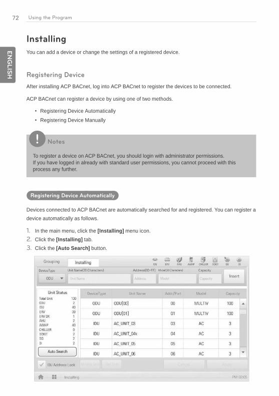
Registering Device Automatically
Devices connected to ACP BACnet are automatically searched for and registered. You can register a device automatically as follows.
1. In the main menu, click the [Installing] menu icon.2. Click the [Installing] tab.3. Click the [Auto Search] button.
73E
NG
LIS
HUsing the Program
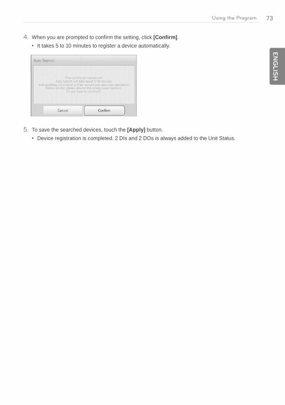
4. When you are prompted to confirm the setting, click [Confirm].It takes 5 to 10 minutes to register a device automatically.
5. To save the searched devices, touch the [Apply] button.Device registration is completed. 2 DIs and 2 DOs is always added to the Unit Status.
74
EN
GLIS
H
Using the Program
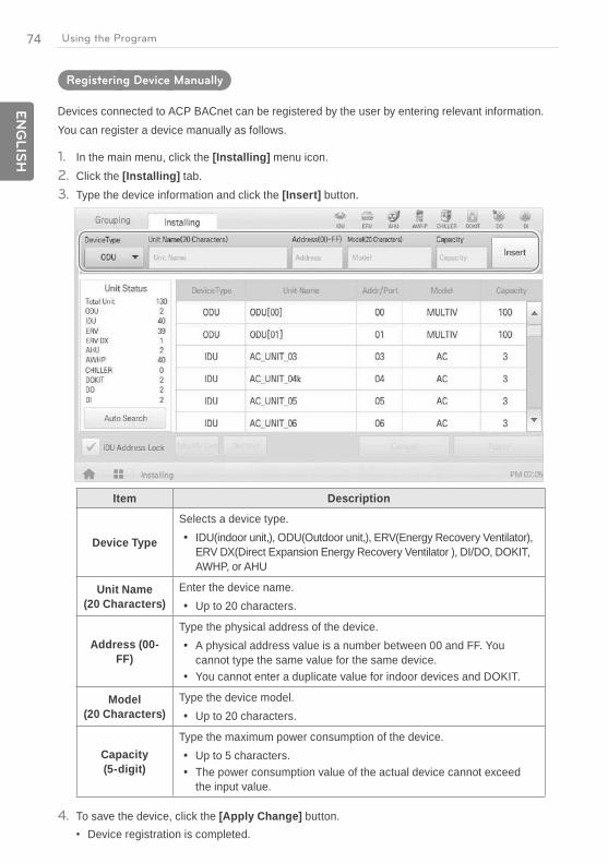
Registering Device Manually
Devices connected to ACP BACnet can be registered by the user by entering relevant information. You can register a device manually as follows.
1. In the main menu, click the [Installing] menu icon.2. Click the [Installing] tab.3. Type the device information and click the [Insert] button.
Item Description
Device Type
Selects a device type. IDU(indoor unit,), ODU(Outdoor unit,), ERV(Energy Recovery Ventilator),
ERV DX(Direct Expansion Energy Recovery Ventilator ), DI/DO, DOKIT, AWHP, or AHU
Unit Name (20 Characters)
Enter the device name. Up to 20 characters.
Address (00-FF)
Type the physical address of the device. A physical address value is a number between 00 and FF. You
cannot type the same value for the same device. You cannot enter a duplicate value for indoor devices and DOKIT.
Model (20 Characters)
Type the device model. Up to 20 characters.
Capacity (5-digit)
Type the maximum power consumption of the device. Up to 5 characters. The power consumption value of the actual device cannot exceed
the input value.
4. To save the device, click the [Apply Change] button.Device registration is completed.
75E
NG
LIS
HUsing the Program
Changing Device
You can change the settings of registered devices.
1. In the main menu, click the [Installing] menu icon.2. Click the [Installing] tab.3. Click a device to be changed in the device list.
The device information is displayed in the device information input box.
4. Type the device information and click the [Modify Unit] button.The changed device information is applied.
5. To save a change, click the [Apply] button.
Deleting Device
Follow these steps to delete a device from the list.
1. In the main menu, click the [Installing] menu icon.2. Click the [Installing] tab.3. In the device list, click a device to be deleted and click the [Del Unit] button.4. When you are prompted to confirm the deletion, click [Confirm].
The selected device is deleted from the list.
5. To save a change, click the [Apply] button.
76
EN
GLIS
H
Using the Program
Managing Device
The following explains how to manage the information for a device added to the system.
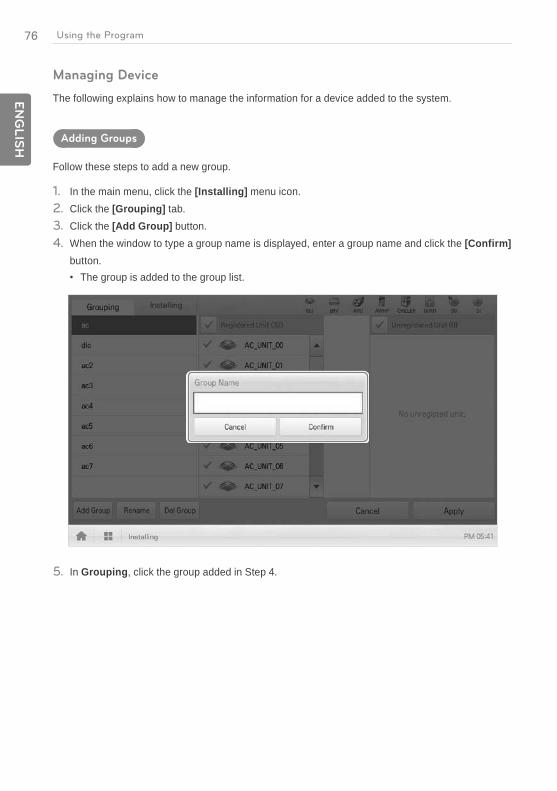
Adding Groups
Follow these steps to add a new group.
1. In the main menu, click the [Installing] menu icon.2. Click the [Grouping] tab.3. Click the [Add Group] button.4. When the window to type a group name is displayed, enter a group name and click the [Confirm]
button.The group is added to the group list.
5. In Grouping, click the group added in Step 4.
77E
NG
LIS
HUsing the Program
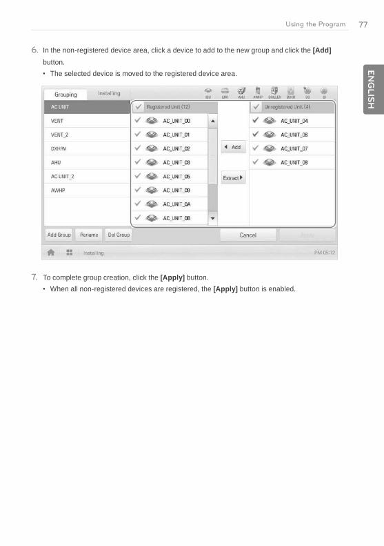
6. In the non-registered device area, click a device to add to the new group and click the [Add] button.
The selected device is moved to the registered device area.
7. To complete group creation, click the [Apply] button.When all non-registered devices are registered, the [Apply] button is enabled.
78
EN
GLIS
H
Using the Program
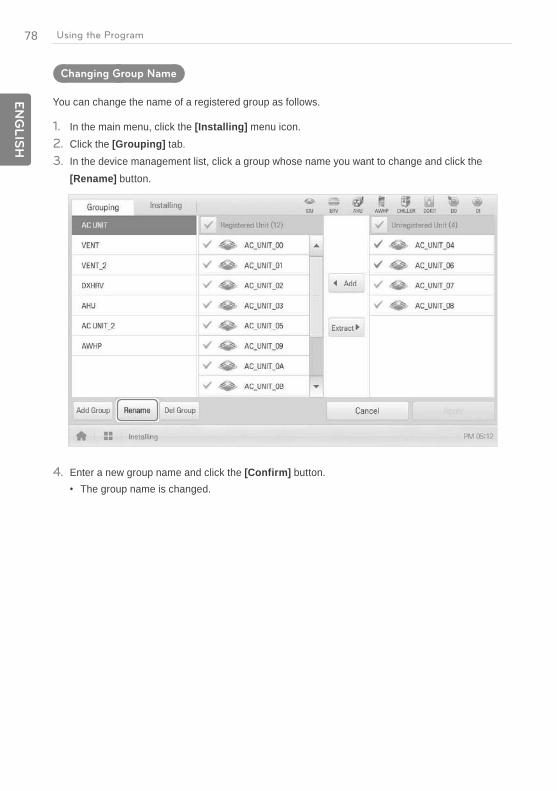
Changing Group Name
You can change the name of a registered group as follows.
1. In the main menu, click the [Installing] menu icon.2. Click the [Grouping] tab.3. In the device management list, click a group whose name you want to change and click the
[Rename] button.
4. Enter a new group name and click the [Confirm] button.The group name is changed.
79E
NG
LIS
HUsing the Program
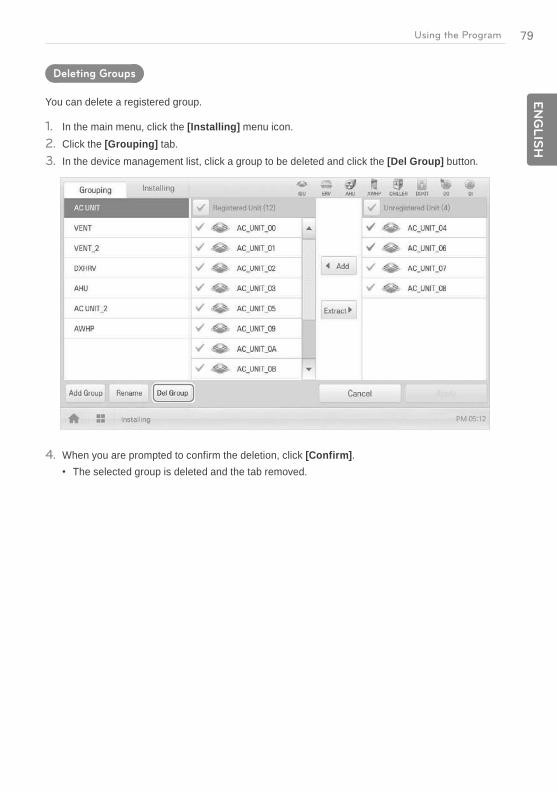
Deleting Groups
You can delete a registered group.
1. In the main menu, click the [Installing] menu icon.2. Click the [Grouping] tab.3. In the device management list, click a group to be deleted and click the [Del Group] button.
4. When you are prompted to confirm the deletion, click [Confirm].The selected group is deleted and the tab removed.
80
EN
GLIS
H
Using the Program
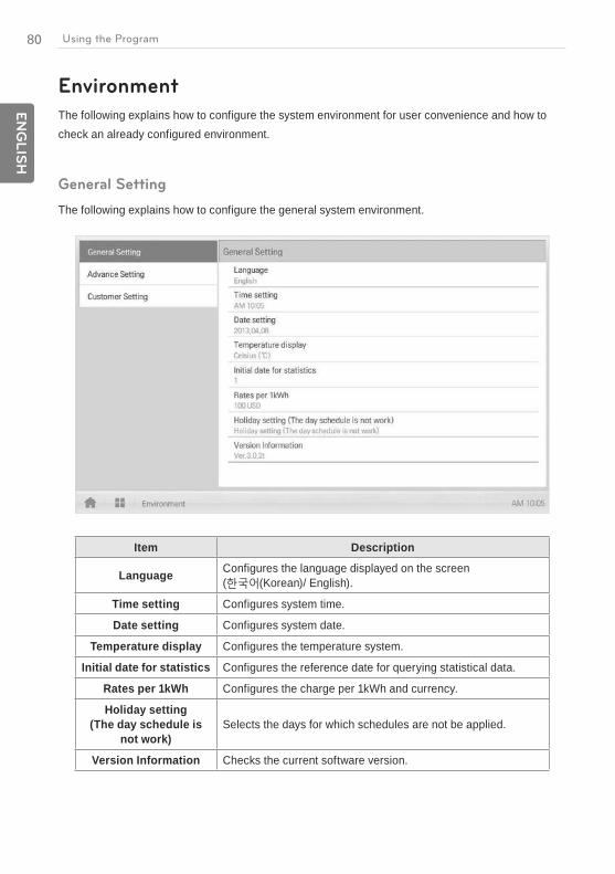
Environment
The following explains how to configure the system environment for user convenience and how to check an already configured environment.
General Setting
The following explains how to configure the general system environment.
Item Description
Language Configures the language displayed on the screen ( (Korean)/ English).
Time setting Configures system time.
Date setting Configures system date.
Temperature display Configures the temperature system.
Initial date for statistics Configures the reference date for querying statistical data.
Rates per 1kWh Configures the charge per 1kWh and currency.
Holiday setting (The day schedule is
not work)Selects the days for which schedules are not be applied.
Version Information Checks the current software version.
81E
NG
LIS
HUsing the Program
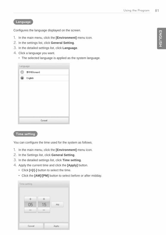
Language
Configures the language displayed on the screen.
1. In the main menu, click the [Environment] menu icon.2. In the settings list, click General Setting.3. In the detailed settings list, click Language.4. Click a language you want.
The selected language is applied as the system language.
Time setting
You can configure the time used for the system as follows.
1. In the main menu, click the [Environment] menu icon.2. In the Settings list, click General Setting.3. In the detailed settings list, click Time setting.4. Apply the current time and click the [Apply] button.
Click [+]/[-] button to select the time.
Click the [AM]/[PM] button to select before or after midday.
82
EN
GLIS
H
Using the Program
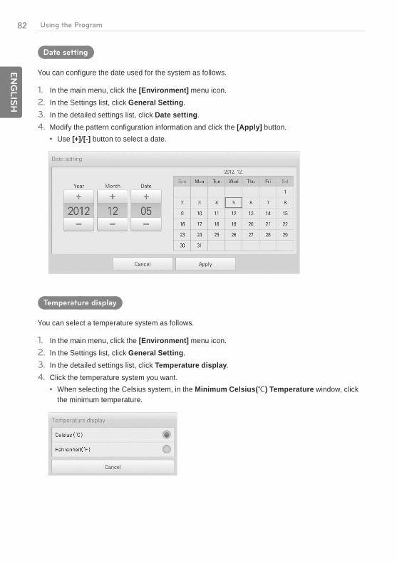
Date setting
You can configure the date used for the system as follows.
1. In the main menu, click the [Environment] menu icon.2. In the Settings list, click General Setting.3. In the detailed settings list, click Date setting.4. Modify the pattern configuration information and click the [Apply] button.
Use [+]/[-] button to select a date.
Temperature display
You can select a temperature system as follows.
1. In the main menu, click the [Environment] menu icon.2. In the Settings list, click General Setting.3. In the detailed settings list, click Temperature display.4. Click the temperature system you want.
When selecting the Celsius system, in the Minimum Celsius( ) Temperature window, click the minimum temperature.

83E
NG
LIS
HUsing the Program
Initial date for statistics
Statistics Reference Date is the date for calculating the indoor unit's operation time by month. The operation time from this date through the previous date to the same date of the next month is calculated and provided as statistical data. You can configure Statistics Reference Date as follows.
1. In the main menu, click the [Environment] menu icon.2. In the Settings list, click General Setting.3. In the detailed settings list, click Initial date for statistics.4. [+]/[-] button to select a date you want and [Apply] button.
Rates per 1kWh
You can configure the charge per kWh and the currency as follows.
1. In the main menu, click the [Environment] menu icon.2. In the Settings list, click General Setting.3. In the detailed settings list, click Rates set.4. Configure the charge/kWh configuration information and click [Apply] button.
rates per(1kWh): Charge per 1kWh.
Currency: Click button to select the desired currency.
84
EN
GLIS
H
Using the Program
Holiday setting(The day schedule is not work)
The following explains how to register an exception date or how to delete a registered date.
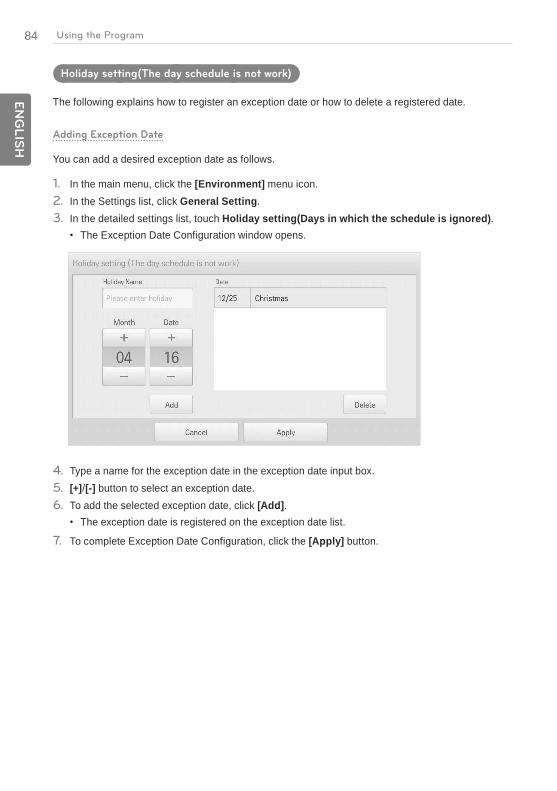
Adding Exception Date
You can add a desired exception date as follows.
1. In the main menu, click the [Environment] menu icon.2. In the Settings list, click General Setting.3. In the detailed settings list, touch Holiday setting(Days in which the schedule is ignored).
The Exception Date Configuration window opens.
4. Type a name for the exception date in the exception date input box.5. [+]/[-] button to select an exception date.6. To add the selected exception date, click [Add].
The exception date is registered on the exception date list.
7. To complete Exception Date Configuration, click the [Apply] button.
85E
NG
LIS
HUsing the Program
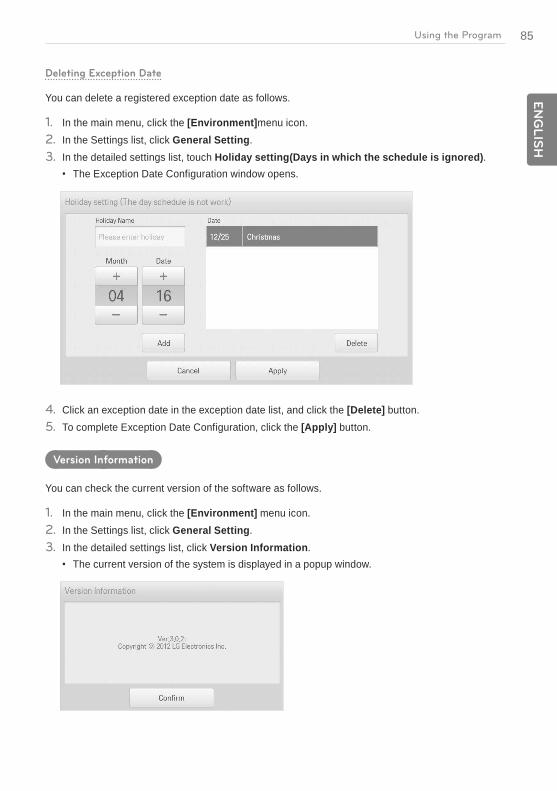
Deleting Exception Date
You can delete a registered exception date as follows.
1. In the main menu, click the [Environment]menu icon.2. In the Settings list, click General Setting.3. In the detailed settings list, touch Holiday setting(Days in which the schedule is ignored).
The Exception Date Configuration window opens.
4. Click an exception date in the exception date list, and click the [Delete] button.5. To complete Exception Date Configuration, click the [Apply] button.
Version Information
You can check the current version of the software as follows.
1. In the main menu, click the [Environment] menu icon.2. In the Settings list, click General Setting.3. In the detailed settings list, click Version Information.
The current version of the system is displayed in a popup window.

86
EN
GLIS
H
Using the Program
Advance Setting
The following explains how to configure the functions necessary for device operation.
Item Description
LGAP setting Master: ACP BACnet must be set to only master. Slave: Not used.
Peak/Demand set
Peak Control: You can use the peak control feature in the auto logic menu.
Demand Control: You can use the demand control feature in the auto logic menu.
Set the operation mode
Priority Control: In Peak/Demand Control menu, control the devices based on the priority of the group.
Outdoor Unit Capacity Control: In the Peak/Demand Control menu, control the outdoor capacity rate per unit.
Temperature difference
for Setback/AutoChangeOver
[+]/[-] button to select the temperature gap.
Update S/W Software upgrade using a USB memory stick. Complete upgrade and restart the system.
DB backup Backup the DB onto a USB memory stick.
Recovery DB Use the DB stored on the USB memory stick to restore the system.

87E
NG
LIS
HUsing the Program
LGAP setting
ACP BACnet can interface with another central controller to control a device. You can configure the interface type with other devices as follows.
1. In the main menu, click the [Environment] menu icon.2. In the Settings list, click Advance Setting.3. In the detailed settings list, click LGAP setting.4. Click a type you want.
Master: ACP BACnet must be set to only master.
Slave: Not used.
Peak/Demand set
You can select a control type to be used for auto logic.
1. In the main menu, click the [Environment] menu icon.2. In the Settings list, click Advance Setting.3. In the detailed settings list, click Peak/Demand set.4. Click a control type to be used for auto logic
Peak Control: You can use the peak control feature in the auto logic menu.
Demand Control: You can use the demand control feature in the auto logic menu.
88
EN
GLIS
H
Using the Program
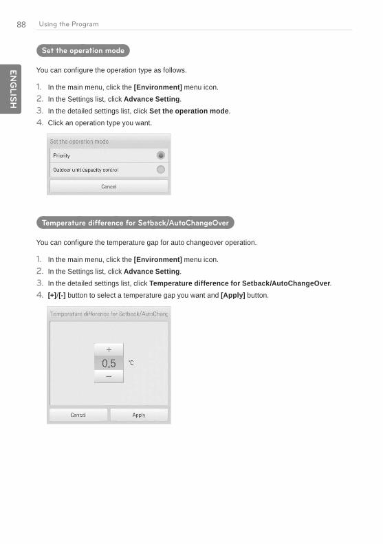
Set the operation mode
You can configure the operation type as follows.
1. In the main menu, click the [Environment] menu icon.2. In the Settings list, click Advance Setting.3. In the detailed settings list, click Set the operation mode.4. Click an operation type you want.
Temperature difference for Setback/AutoChangeOver
You can configure the temperature gap for auto changeover operation.
1. In the main menu, click the [Environment] menu icon.2. In the Settings list, click Advance Setting.3. In the detailed settings list, click Temperature difference for Setback/AutoChangeOver.4. [+]/[-] button to select a temperature gap you want and [Apply] button.

89E
NG
LIS
HUsing the Program
Update S/W
You can upgrade the current version of software as follows.
Notes
To update the software, you need a USB memory stick which has patch.tar file in the ramdisk folder.
1. Connect the USB memory to ACP BACnet.2. In the main menu, click the [Environment] menu icon.3. In the Settings list, click Advance Setting.4. In the detailed settings list, click Update S/W.5. When the software update window appears, click the [Update S/W] button.
When the update has been completed, the program restarts.

90
EN
GLIS
H
Using the Program
DB backup
You can backup the database stored in the system to USB memory as follows.
1. Connect the USB memory to ACP BACnet.2. In the main menu, click the [Environment] menu icon.3. In the Settings list, click Advance Setting.4. In the detailed settings list, click DB backup.5. When the DB Backup window appears, click the [DB backup] button.
Recovery DB
You can use the database stored on USB memory to restore the system database.
1. Connect the USB memory stick to ACP BACnet.2. In the main menu, click the [Environment] menu icon.3. In the Settings list, click Advance Setting.4. In the detailed settings list, click Recovery DB.5. When the DB Recovery window appears, click the [Recovery DB] button.
When the DB recovery has been completed, the program restarts.
91E
NG
LIS
HUsing the Program
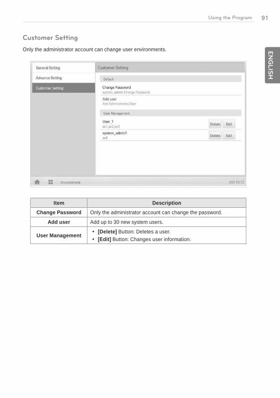
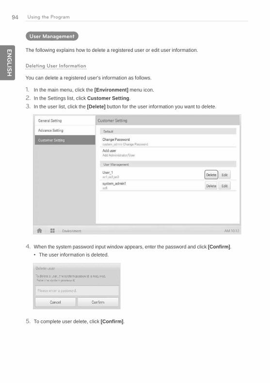
Customer Setting
Only the administrator account can change user environments.
Item Description
Change Password Only the administrator account can change the password.
Add user Add up to 30 new system users.
User Management [Delete] Button: Deletes a user. [Edit] Button: Changes user information.
92
EN
GLIS
H
Using the Program
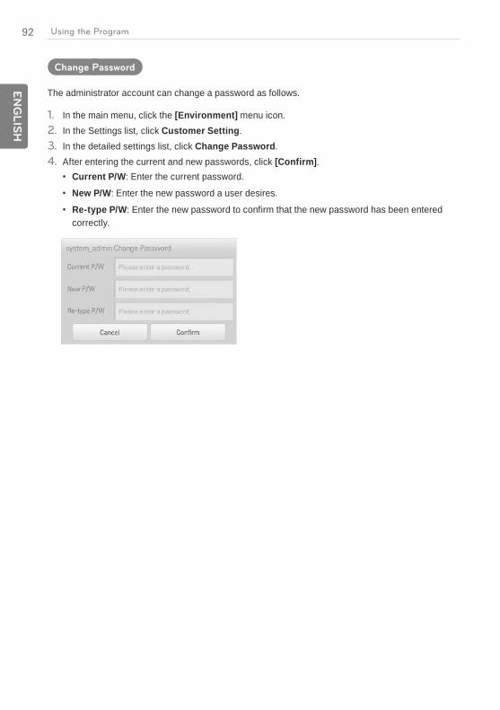
Change Password
The administrator account can change a password as follows.
1. In the main menu, click the [Environment] menu icon.2. In the Settings list, click Customer Setting.3. In the detailed settings list, click Change Password.4. After entering the current and new passwords, click [Confirm].
Current P/W: Enter the current password.
New P/W: Enter the new password a user desires.
Re-type P/W: Enter the new password to confirm that the new password has been entered correctly.
93E
NG
LIS
HUsing the Program
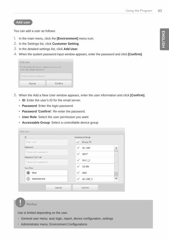
Add user
You can add a user as follows.
1. In the main menu, click the [Environment] menu icon.2. In the Settings list, click Customer Setting.3. In the detailed settings list, click Add User.4. When the system password input window appears, enter the password and click [Confirm].
5. When the Add a New User window appears, enter the user information and click [Confirm].ID: Enter the user's ID for the email server.
Password: Enter the login password.
Password 'Confirm': Re-enter the password.
User Role: Select the user permission you want
Accessable Group: Select a controllable device group
Notes
Use is limited depending on the user.
General user menu: auto logic, report, device configuration, settings
Administrator menu: Environment Configurations
94
EN
GLIS
H
Using the Program
User Management
The following explains how to delete a registered user or edit user information.
Deleting User Information
You can delete a registered user's information as follows.
1. In the main menu, click the [Environment] menu icon.2. In the Settings list, click Customer Setting.3. In the user list, click the [Delete] button for the user information you want to delete.
4. When the system password input window appears, enter the password and click [Confirm].The user information is deleted.
5. To complete user delete, click [Confirm].

95E
NG
LIS
HUsing the Program
Editing User Information
You can edit a registered user's information as follows.
1. In the main menu, click the [Environment] menu icon.2. In the Settings list, click Customer Setting.3. In the user list, click the [Edit] button for the user information you want to edit.
4. When the system password input window appears, enter the password, click [Confirm].

96
EN
GLIS
H
Using the Program
5. When the Edit User window appears, enter the user information and click [Confirm].The updated user information is applied.
6. To complete user edit, click [Confirm].

97E
NG
LIS
HInstalling ACP BACnet
Installing ACP BACnet
Installing ACP BACnet
This chapter describes how to install the ACP BACnet to use.
In order to use the ACP BACnet, the installation should be performed by the following order.
STEP 1. Check the cautions during the ACP BACnet installationBefore installing the ACP BACnet, check the cautions.
STEP 2. Study the cable connections diagram of the entire systemStudy the cable connection diagram of the site where the ACP BACnet is installed.
STEP 3. Set the indoor unit addressSet the address of the ACP BACnet not to be overlapped with the connecting indoor unit.
STEP 4. Set PI485 and connect cablesSet DIP switch of PI485 correctly, and connect RS-485 communication cable.
STEP 5. Install ACP BACnet and connect cablesInstall the ACP BACnet, and set network and other settings.
STEP 6. Set ACP BACnet network addressSet the network address to be able to access the ACP BACnet through internet.
STEP 7. Set ACP BACnet functionsSet language, peak/demand, whether to use schedule, whether to use power display, etc.
STEP 8. Set Web GUI access environmentSet the access environment in Web GUI, which is the operation program of the ACP BACnet.
STEP 9. Input indoor unit and ventilator informationSet the access environment in Web GUI, which is the operation program of the ACP BACnet.
STEP 10. Verify and check ACP BACnet installationVerify and check whether the ACP BACnet is properly installed.
98
EN
GLIS
H
Installing ACP BACnet
Caution
Installing the ACP BACnet
The ACP BACnet installation work needs the professional technique. Therefore, the installation described in this chapter should be performed by the certified installation professional.
Consult the service center or the professional installation agency certified by us about any question or request related to the installation.
Check points during the ACP BACnet installationThe number of PI485 connected to one RS-485 communication line
- ACP BACnet provides 4 RS-485 ports for indoor unit connection. (CH 1~4) - Up to 16 PI485 for outdoor unit can be connected to one RS-485 port, and up to 31 PI485 for - SINGLE/ventilation can be connected.The number of the indoor units that can be connected to one ACP BACnet
- One ACP BACnet can be connected up to 256 indoor units. To one RS-485 port, all of 256 indoor units, which is the maximum number that can be connected to the ACP BACnet, may be connected. But, to improve the communication performance of RS-485, it is recommended to be divided and connected to 4 ports.
RS-485 communication cable connection
- There is a polarity in RS-485 communication cable connection, so be careful not to reverse the connection of the two cables.
- Do not let the length of RS-485 communication cable exceed total of 1 Km. - RS-485 communication cable must be connected with BUS type.IP address of the ACP BACnet
- IP address of the ACP BACnet, address of Gateway, and Net mask must be requested to the person in charge of the network of the corresponding site.
Caution
RS-485 Connection of the ventilation equipment
To connect ventilation equipment, it is recommended to use the ports other than RS-485 communication ports which are connected to air conditioners.
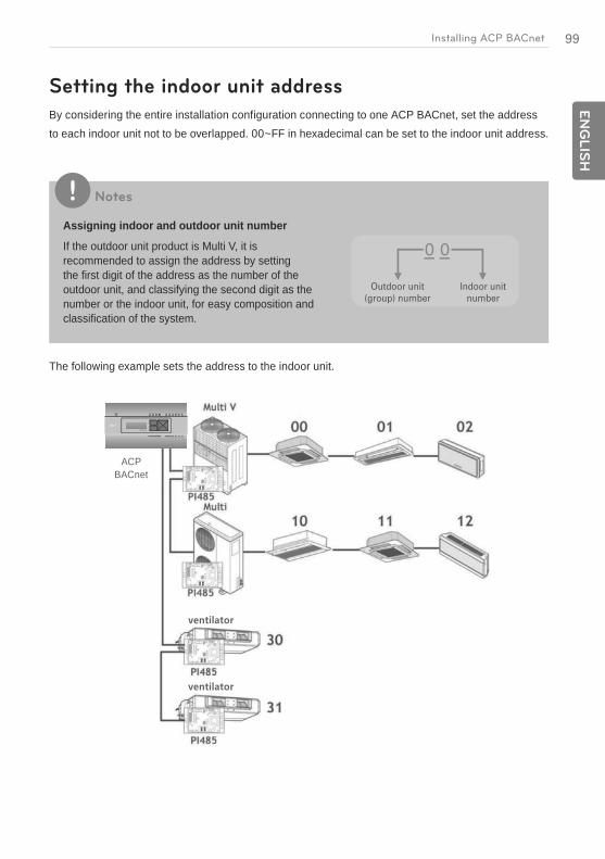
99E
NG
LIS
HInstalling ACP BACnet
Setting the indoor unit address
By considering the entire installation configuration connecting to one ACP BACnet, set the address to each indoor unit not to be overlapped. 00~FF in hexadecimal can be set to the indoor unit address.
Notes
Assigning indoor and outdoor unit number
If the outdoor unit product is Multi V, it is recommended to assign the address by setting the first digit of the address as the number of the outdoor unit, and classifying the second digit as the number or the indoor unit, for easy composition and classification of the system.
The following example sets the address to the indoor unit.
BACnet
PQNFB17C0
ACP BACnet

100
EN
GLIS
H
Installing ACP BACnet
When the ACP BACnet is interconnected with the AC Manager, the ventilator can be installed together and controlled.
The above figure shows the example that sets the addresses of 30 and 31 to the ventilators and connects to the ACP BACnet.
Notes
How to set the central control address of the indoor unit
The central control address setting method may be different for each indoor unit product or remote control type, so set the address by referring to the manual of the indoor unit product or wired remote controller.
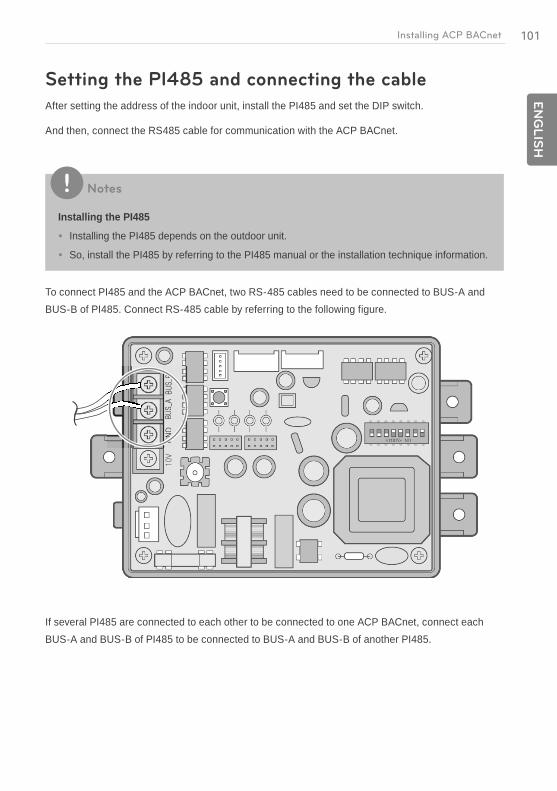
101E
NG
LIS
HInstalling ACP BACnet
Setting the PI485 and connecting the cable
After setting the address of the indoor unit, install the PI485 and set the DIP switch.
And then, connect the RS485 cable for communication with the ACP BACnet.
Notes
Installing the PI485
Installing the PI485 depends on the outdoor unit.
So, install the PI485 by referring to the PI485 manual or the installation technique information.
To connect PI485 and the ACP BACnet, two RS-485 cables need to be connected to BUS-A and BUS-B of PI485. Connect RS-485 cable by referring to the following figure.
If several PI485 are connected to each other to be connected to one ACP BACnet, connect each BUS-A and BUS-B of PI485 to be connected to BUS-A and BUS-B of another PI485.
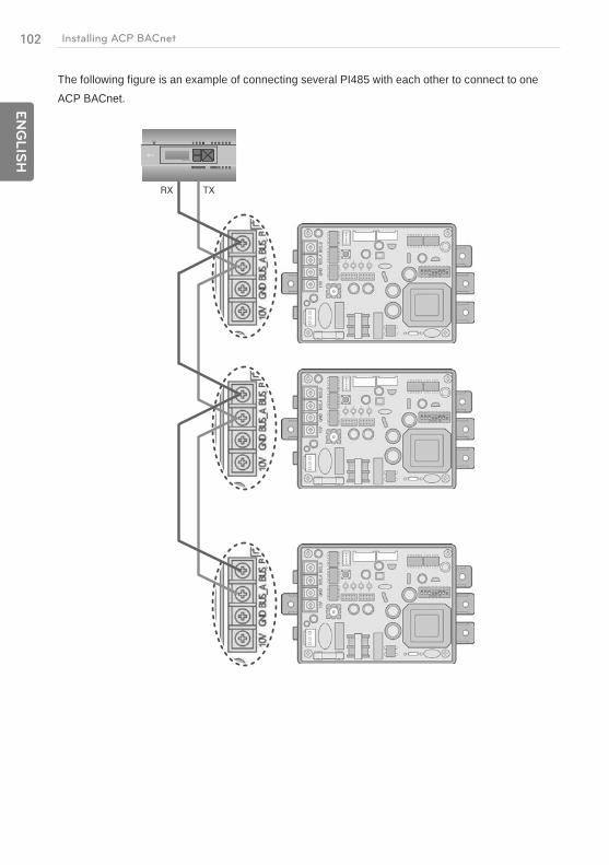
102
EN
GLIS
H
Installing ACP BACnet
The following figure is an example of connecting several PI485 with each other to connect to one ACP BACnet.
PQNFB17C0
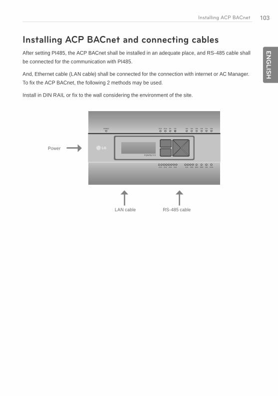
103E
NG
LIS
HInstalling ACP BACnet
Installing ACP BACnet and connecting cables
After setting PI485, the ACP BACnet shall be installed in an adequate place, and RS-485 cable shall be connected for the communication with PI485.
And, Ethernet cable (LAN cable) shall be connected for the connection with internet or AC Manager. To fix the ACP BACnet, the following 2 methods may be used.
Install in DIN RAIL or fix to the wall considering the environment of the site.
PQNFB17C0
Power
LAN cable RS-485 cable
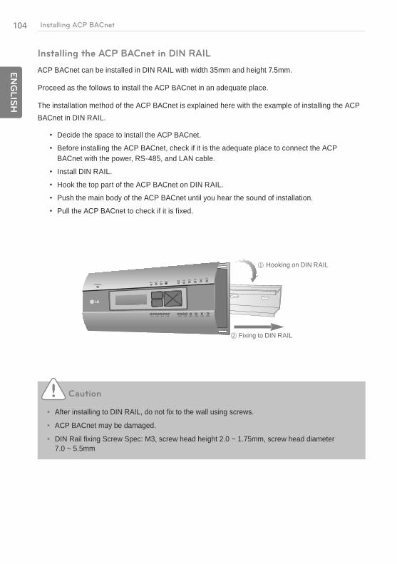
104
EN
GLIS
H
Installing ACP BACnet
Installing the ACP BACnet in DIN RAIL
ACP BACnet can be installed in DIN RAIL with width 35mm and height 7.5mm.
Proceed as the follows to install the ACP BACnet in an adequate place.
The installation method of the ACP BACnet is explained here with the example of installing the ACP BACnet in DIN RAIL.
Decide the space to install the ACP BACnet.
Before installing the ACP BACnet, check if it is the adequate place to connect the ACP BACnet with the power, RS-485, and LAN cable.
Install DIN RAIL.
Hook the top part of the ACP BACnet on DIN RAIL.
Push the main body of the ACP BACnet until you hear the sound of installation.
Pull the ACP BACnet to check if it is fixed.
Hooking on DIN RAIL
Fixing to DIN RAIL
Caution
After installing to DIN RAIL, do not fix to the wall using screws.
ACP BACnet may be damaged.
DIN Rail fixing Screw Spec: M3, screw head height 2.0 ~ 1.75mm, screw head diameter 7.0 ~ 5.5mm
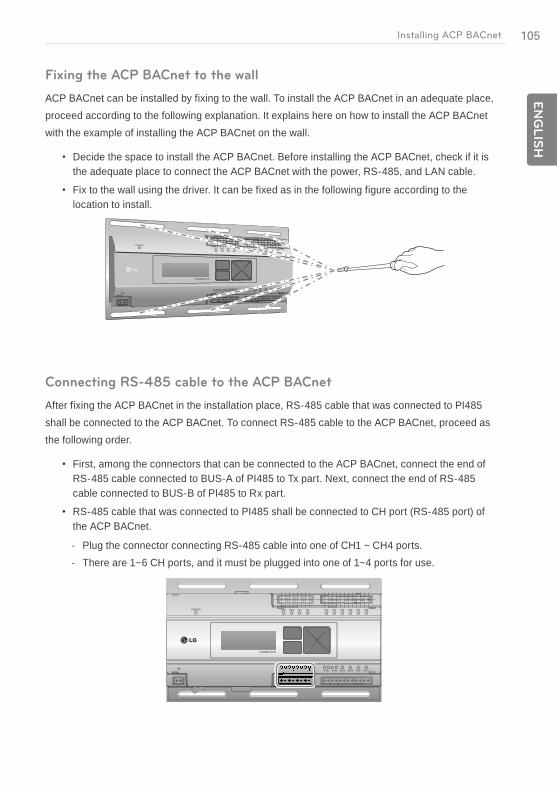
105E
NG
LIS
HInstalling ACP BACnet
Fixing the ACP BACnet to the wall
ACP BACnet can be installed by fixing to the wall. To install the ACP BACnet in an adequate place, proceed according to the following explanation. It explains here on how to install the ACP BACnet with the example of installing the ACP BACnet on the wall.
Decide the space to install the ACP BACnet. Before installing the ACP BACnet, check if it is the adequate place to connect the ACP BACnet with the power, RS-485, and LAN cable.
Fix to the wall using the driver. It can be fixed as in the following figure according to the location to install.
PQNFB17C0
Connecting RS-485 cable to the ACP BACnet
After fixing the ACP BACnet in the installation place, RS-485 cable that was connected to PI485 shall be connected to the ACP BACnet. To connect RS-485 cable to the ACP BACnet, proceed as the following order.
First, among the connectors that can be connected to the ACP BACnet, connect the end of RS-485 cable connected to BUS-A of PI485 to Tx part. Next, connect the end of RS-485 cable connected to BUS-B of PI485 to Rx part.
RS-485 cable that was connected to PI485 shall be connected to CH port (RS-485 port) of the ACP BACnet.
- Plug the connector connecting RS-485 cable into one of CH1 ~ CH4 ports. - There are 1~6 CH ports, and it must be plugged into one of 1~4 ports for use.
PQNFB17C0
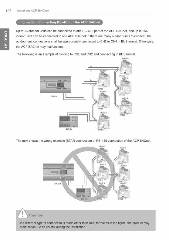
106
EN
GLIS
H
Installing ACP BACnet
Information: Connecting RS-485 of the ACP BACnet
Up to 16 outdoor units can be connected to one RS-485 port of the ACP BACnet, and up to 256 indoor units can be connected to one ACP BACnet. If there are many outdoor units to connect, the outdoor unit connections shall be appropriately connected to CH1 to CH4 in BUS format. Otherwise, the ACP BACnet may malfunction.
The following is an example of dividing to CH1 and CH2 and connecting in BUS format.
PQNFB17C0
BACnet
The next shows the wrong example (STAR connection) of RS-485 connection of the ACP BACnet.
PQNFB17C0
BACnet
Caution
If a different type of connection is made other than BUS format as in the figure, the product may malfunction. So be careful during the installation.

107E
NG
LIS
HInstalling ACP BACnet
Connecting Ethernet cable (LAN cable) to the ACP BACnet
After connecting the ACP BACnet and RS-485 cable, Ethernet cable shall be connected to the ACP BACnet.
ACP BACnet may be connected to hub through Ethernet cable, or directly to AC Manager.
Connecting the ACP BACnet and hub
It is the case of connecting the ACP BACnet to the basic internet network installed at the site, and it is generally connected to the hub.
In such case, Ethernet cable shall be connected as a direct cable.
Use Ethernet cable (direct cable) to connect to LAN port of the ACP BACnet.
Connecting ACP BACnet and PC
It is the case of installing AC Manager in a separate PC and connecting ACP BACnet and PC directly.
In such case, Ethernet cable shall be connected as a cross cable.
Use Ethernet cable (cross cable) to connect to LAN port of the ACP BACnet.
Connection with hub
Direct cable
Direct connection with PC
Cross cable
Caution
Ethernet cable types
You must distinguish if the Ethernet cable to connect is a direct cable or a cross cable.
Also, connect after checking the existence of problem in the cable using LAN tester.

108
EN
GLIS
H
Installing ACP BACnet
Setting the ACP BACnet network address
After connecting the ACP BACnet to various devices via the cable, the network environment of the ACP BACnet should be set by driving the ACP BACnet. The following information should be set for using the ACP BACnet.
IP address of the ACP BACnet
Gateway address
Net mask
Caution
Setting the network environment information
If the above information is not entered, the communication error may be occurred or it may be impossible to control by the ACP BACnet. So, be careful to correctly input.
Before configuring the ACP BACnet environment
The network environment of the ACP BACnet can be set by the LCD and the buttons at the front side of the ACP BACnet.
The current ACP BACnet information and the menu are displayed on the LCD, and the menu can be changed and selected by pressing SET and buttons.
PQNFB17C0 PQNFB17C0
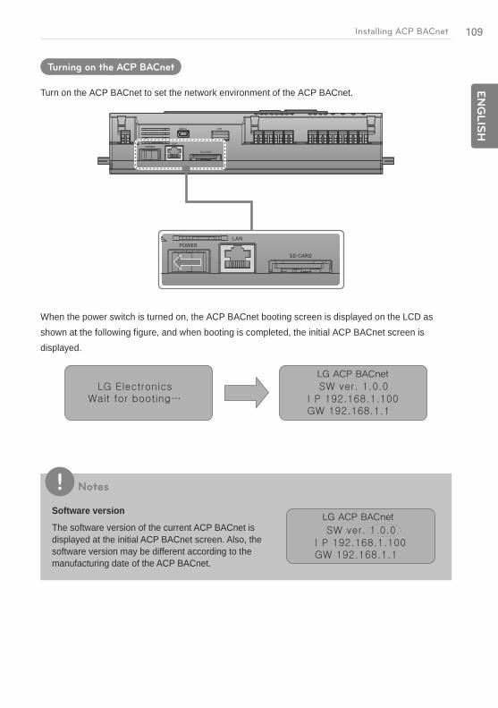
109E
NG
LIS
HInstalling ACP BACnet
Turning on the ACP BACnet
Turn on the ACP BACnet to set the network environment of the ACP BACnet.
When the power switch is turned on, the ACP BACnet booting screen is displayed on the LCD as shown at the following figure, and when booting is completed, the initial ACP BACnet screen is displayed.
Notes
Software version
The software version of the current ACP BACnet is displayed at the initial ACP BACnet screen. Also, the software version may be different according to the manufacturing date of the ACP BACnet.
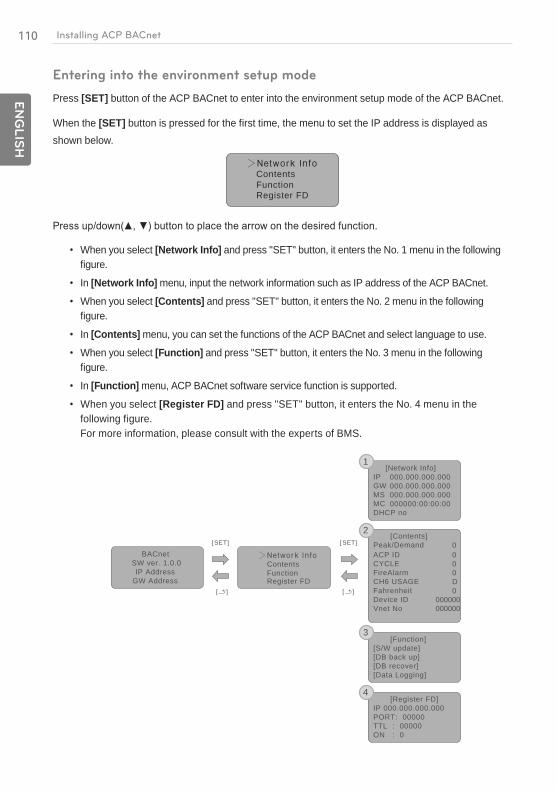
110
EN
GLIS
H
Installing ACP BACnet
Entering into the environment setup mode
Press [SET] button of the ACP BACnet to enter into the environment setup mode of the ACP BACnet.
When the [SET] button is pressed for the first time, the menu to set the IP address is displayed as shown below.
ContentsFunctionRegister FD
When you select [Network Info] and press "SET" button, it enters the No. 1 menu in the following figure.
In [Network Info] menu, input the network information such as IP address of the ACP BACnet.
When you select [Contents] and press "SET" button, it enters the No. 2 menu in the following figure.
In [Contents] menu, you can set the functions of the ACP BACnet and select language to use.
When you select [Function] and press "SET" button, it enters the No. 3 menu in the following figure.
In [Function] menu, ACP BACnet software service function is supported.
When you select [Register FD] and press "SET" button, it enters the No. 4 menu in the following figure. For more information, please consult with the experts of BMS.
[Network Info]IPGWMSMCDHCP no
000.000.000.000000.000.000.000000.000.000.000000000:00:00:00
[Contents]Peak/DemandACP IDCYCLEFireAlarmCH6 USAGE
0000D
Fahrenheit 0Device ID 000000
000000Vnet No
[Function][S/W update][DB back up][DB recover][Data Logging]
BACnetSW ver. 1.0.0IP Address
GW Address
Contents Function Register FD
]TES[]TES[
1
2
3
[Register FD]IP 000.000.000.000PORT: 00000TTL : 00000ON : 0
4
[ ][ ]

111E
NG
LIS
HInstalling ACP BACnet
Caution
[Function] menu is used by the system air conditioner service technician, so user shallnever use this function.
If this function is incorrectly used, it may cause disorder of the ACP BACnet.
How to set network address
DOWN
UP
To change the network setting, locate the arrow on the corresponding setting position, and press [SET] button to enter the corresponding setting screen.
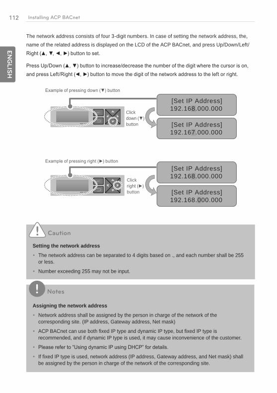
112
EN
GLIS
H
Installing ACP BACnet
The network address consists of four 3-digit numbers. In case of setting the network address, the, name of the related address is displayed on the LCD of the ACP BACnet, and press Up/Down/Left/
[Set IP Address]192.168.000.000
[Set IP Address]192.167.000.000
[Set IP Address]192.168.000.000
[Set IP Address]192.168.000.000
Click
button
Click
button
Caution
Setting the network address
The network address can be separated to 4 digits based on ., and each number shall be 255 or less.
Number exceeding 255 may not be input.
Notes
Assigning the network address
Network address shall be assigned by the person in charge of the network of the corresponding site. (IP address, Gateway address, Net mask)
ACP BACnet can use both fixed IP type and dynamic IP type, but fixed IP type is recommended, and if dynamic IP type is used, it may cause inconvenience of the customer.
If fixed IP type is used, network address (IP address, Gateway address, and Net mask) shall be assigned by the person in charge of the network of the corresponding site.
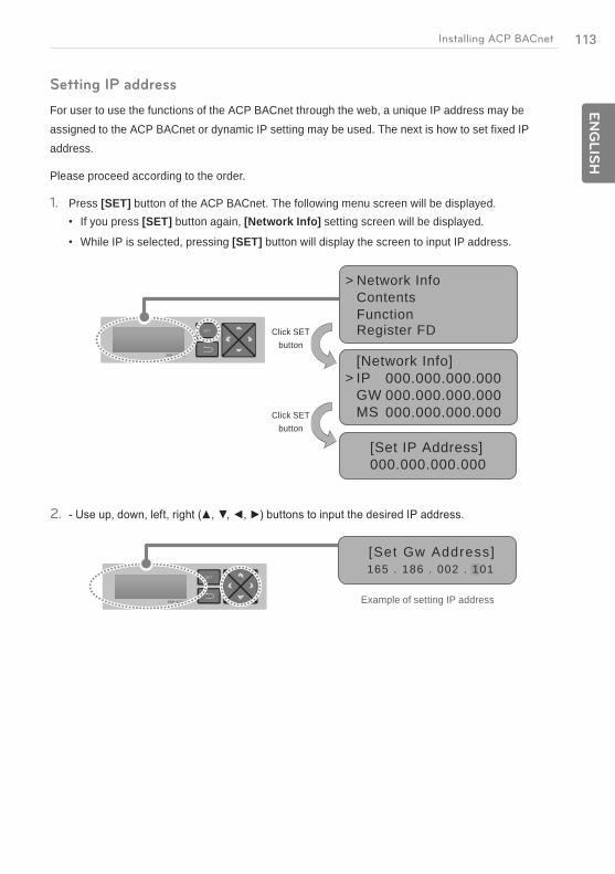
113E
NG
LIS
HInstalling ACP BACnet
Setting IP address
For user to use the functions of the ACP BACnet through the web, a unique IP address may be assigned to the ACP BACnet or dynamic IP setting may be used. The next is how to set fixed IP address.
Please proceed according to the order.
1. Press [SET] button of the ACP BACnet. The following menu screen will be displayed.If you press [SET] button again, [Network Info] setting screen will be displayed.
While IP is selected, pressing [SET] button will display the screen to input IP address.
>[Network Info]IPGWMS
000.000.000.000000.000.000.000000.000.000.000
[Set IP Address]000.000.000.000
Network InfoContentsFunctionRegister FD
>
Click SET button
Click SET button
2.
[Set Gw Address]165 . 186 . 002 . 101
Example of setting IP address
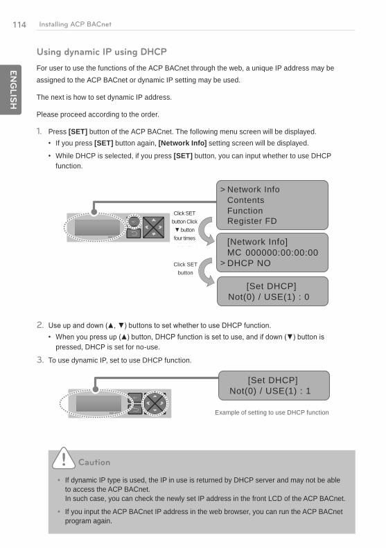
114
EN
GLIS
H
Installing ACP BACnet
Using dynamic IP using DHCP
For user to use the functions of the ACP BACnet through the web, a unique IP address may be assigned to the ACP BACnet or dynamic IP setting may be used.
The next is how to set dynamic IP address.
Please proceed according to the order.
1. Press [SET] button of the ACP BACnet. The following menu screen will be displayed.If you press [SET] button again, [Network Info] setting screen will be displayed.
While DHCP is selected, if you press [SET] button, you can input whether to use DHCP function.
Network InfoContentsFunctionRegister FD
>
>
[Set DHCP]Not(0) / USE(1) : 0
[Network Info]MCDHCP NO
000000:00:00:00Click SET
button
Click SET button Click
four times
2.
pressed, DHCP is set for no-use.
3. To use dynamic IP, set to use DHCP function.
1 1[Set DHCP]
Not(0) / USE(1) : 1
Example of setting to use DHCP function
Caution
If dynamic IP type is used, the IP in use is returned by DHCP server and may not be able to access the ACP BACnet. In such case, you can check the newly set IP address in the front LCD of the ACP BACnet.
If you input the ACP BACnet IP address in the web browser, you can run the ACP BACnet program again.

115E
NG
LIS
HInstalling ACP BACnet
Checking ACP BACnet access
It checks whether the ACP BACnet network address setting is properly done.
You can check the possibility of accessing the ACP BACnet through PING test.
1. You can open the following DOS window through Windows "Start", "Run", "cmd" input.
2. In DOS screen, input "ping <ACP BACnet IP address>" as follows to run PING test.
When the network setting is properly done
When the network setting is not properly done
116
EN
GLIS
H
Installing ACP BACnet
Notes
When you connected the ACP BACnet and PC through a cross cable, but you cannot access the ACP BACnet
Check IP address of the ACP BACnet and IP address of the PC.
if the first three digits of the IP address of the PC is the same as the first three digits of the IP address of the ACP BACnet.
from the IP address of the ACP BACnet. Set as follows, and try again. - Setting of the ACP BACnet
Subnet Mask: 255.255.255.0 - Setting of the PC
Subnet Mask: 255.255.255.0 Check the status of the Ethernet cable (LAN cable).
Notes
When PC and ACP BACnet are connected together in a hub or a switch hub, and you cannot access the ACP BACnet.
If it is right after changing the IP setting of the ACP BACnet, reset the power of the ACP BACnet.
If it is right after connecting LAN cable to the hub or switch, it may take time for the hub or the switch to recognize the ACP BACnet. In such case, it may help to turn off and turn on the power of the hub or the switch.
Check the status of the Ethernet cable (LAN cable).
Check ARP table of the PC to see if the IP address of the ACP BACnet correctly corresponds to the MAC address. If duplicate MAC addresses correspond to one IP address, or if different address from the MAC address of the PC is output, there may be a host with the same IP address as the IP address of the ACP BACnet. In such case, the IP address of the ACP BACnet or the IP address of the corresponding host shall be changed.
How to check ARP table

117E
NG
LIS
HInstalling ACP BACnet
Setting the functions of the ACP BACnet
The following functions can be set by using the menu of the ACP BACnet:
Select Peak or Demand
Setting the attributes of CH6
Fire Alarm function
Fahrenheit/Celsius setting function
Device ID setting function
Vnet number setting function
Foreign Device register function
Before setting the functions of the ACP BACnet
The function setting of the ACP BACnet should be changed depending on the case that only the ACP BACnet is used or the case that the ACP BACnet is interconnected with the external devices such as AC Manager, power distribution indicator, and Demand controller.
In general, the function of the ACP BACnet should be set and used as follows:
When only ACP BACnet is used
When ACP BACnet interfaces with AC Manager
Peak or demand selection function Set to peak function Set to demand function
Schedule function Set to use schedule function Set to no-use of schedule function
Power display function Set to use if it interfaces with power distribution indicator, and set to no-use if it does not interface..
Caution
Setting to use the power display
If the ACP BACnet and the power distribution indicator are not connected, the power display function should be set to no-use.
If it is set to use, be careful since the control speed of the ACP BACnet will be slower.
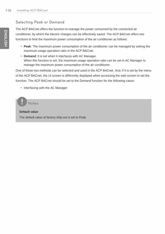
118
EN
GLIS
H
Installing ACP BACnet
Selecting Peak or Demand
The ACP BACnet offers the function to manage the power consumed by the connected air conditioner, by which the electric charges can be effectively saved. The ACP BACnet offers two functions to limit the maximum power consumption of the air conditioner as follows:
Peak: The maximum power consumption of the air conditioner can be managed by setting the maximum usage operation ratio in the ACP BACnet.
Demand: It is set when it interfaces with AC Manager.When this function is set, the maximum usage operation ratio can be set in AC Manager to manage the maximum power consumption of the air conditioner.
One of these two methods can be selected and used in the ACP BACnet. And, if it is set by the menu of the ACP BACnet, the UI screen is differently displayed when accessing the web screen to set the function. The ACP BACnet should be set to the Demand function for the following cases:
Interfacing with the AC Manager
Notes
Default value
The default value at factory ship-out is set to Peak.

119E
NG
LIS
HInstalling ACP BACnet
Change the power control method as follows:
1. When you press [SET]of the ACP BACnet to select [Contents], and press [SET] button again. While [Peak/Demand] is selected, pressing [SET] button will display the screen to select peak or demand method.
Network InfoContentsFunctionRegister FD
>
>
[Set PeakDemand]PK(0) / DMD(1) : 0
[Contents]Peak/DemandLanguageSchedule
000
Click SET
button
Click SET
button
2.
[Set PeakDemand]PK(0) / DMD(1) : 1
Example of setting to use demand function
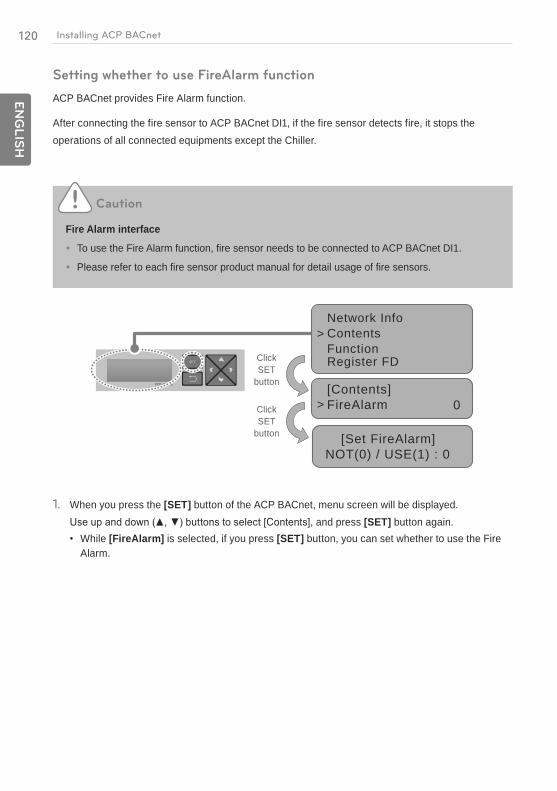
120
EN
GLIS
H
Installing ACP BACnet
Setting whether to use FireAlarm function
ACP BACnet provides Fire Alarm function.
After connecting the fire sensor to ACP BACnet DI1, if the fire sensor detects fire, it stops the operations of all connected equipments except the Chiller.
Caution
Fire Alarm interface
To use the Fire Alarm function, fire sensor needs to be connected to ACP BACnet DI1.
Please refer to each fire sensor product manual for detail usage of fire sensors.
Network InfoContentsFunctionRegister FD
>
>
[Set FireAlarm]NOT(0) / USE(1) : 0
[Contents]FireAlarm 0
Click SET
button
Click SET
button
1. When you press the [SET] button of the ACP BACnet, menu screen will be displayed., and press [SET] button again.
While [FireAlarm] is selected, if you press [SET] button, you can set whether to use the Fire Alarm.

121E
NG
LIS
HInstalling ACP BACnet
Setting whether to use CH6 function
To connect to the Chiller from the ACP BACnet, M (Chiller) shall be selected in CH6 USAGE.
D (demand controller) setting is not used.
1. When you press the [SET] button of the ACP BACnet, menu screen will be displayed., and press [SET] button again.
While [CH6 USAGE] is selected, if you press [SET] button, you can select one from D (Demand) or M (Modbus).
Network InfoContentsFunctionRegister FD
>
>
[Set CH6 USAGE]Demand/Modbus: D
[Contents]CH6 USAGE D
Click SET
button
Click SET
button
Software service function
The following software service function can be run using the menu of the ACP BACnet.
This function shall only be used by the specialized service technician, and negligent use may cause failure of the ACP BACnet system.
Software update
Data backup
Data recovery
RS-485 data logging
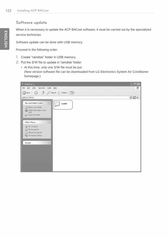
122
EN
GLIS
H
Installing ACP BACnet
Software update
When it is necessary to update the ACP BACnet software, it must be carried out by the specialized service technician.
Software update can be done with USB memory.
Proceed in the following order.
1.
2.
At this time, only one S/W file must be put. (New version software file can be downloaded from LG Electronics System Air Conditioner homepage.)
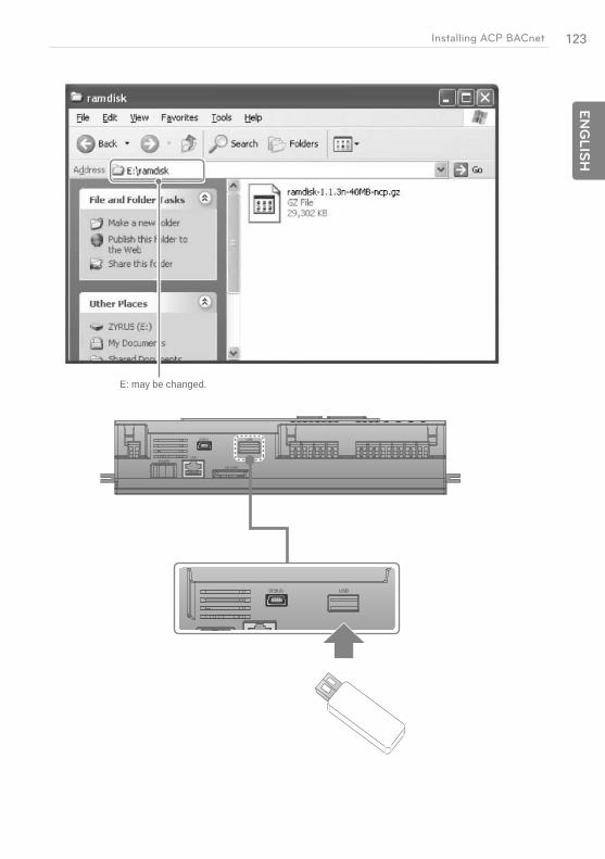
123E
NG
LIS
HInstalling ACP BACnet
E: may be changed.
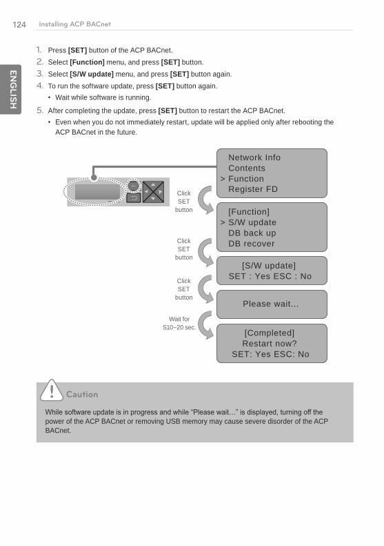
124
EN
GLIS
H
Installing ACP BACnet
1. Press [SET] button of the ACP BACnet.2. Select [Function] menu, and press [SET] button.3. Select [S/W update] menu, and press [SET] button again.4. To run the software update, press [SET] button again.
Wait while software is running.
5. After completing the update, press [SET] button to restart the ACP BACnet.Even when you do not immediately restart, update will be applied only after rebooting the ACP BACnet in the future.
Network InfoContentsFunctionRegister FD
>
[Function]S/W updateDB back upDB recover
>
[S/W update]SET : Yes ESC : No
[Completed]Restart now?
SET: Yes ESC: No
Please wait...
Click SET
button
Click SET
button
Click SET
button
Wait for S10~20 sec.
Caution
power of the ACP BACnet or removing USB memory may cause severe disorder of the ACP BACnet.

125E
NG
LIS
HInstalling ACP BACnet
Data backup
If ACP BACnet data backup is necessary, it must be carried out by the specialized service technician.
Data backup can be done with USB memory or SD card.
Proceed in the following or der.
1. Insert USB memory or SD card into the ACP BACnet. (Refer to software update for USB memory insertion.)
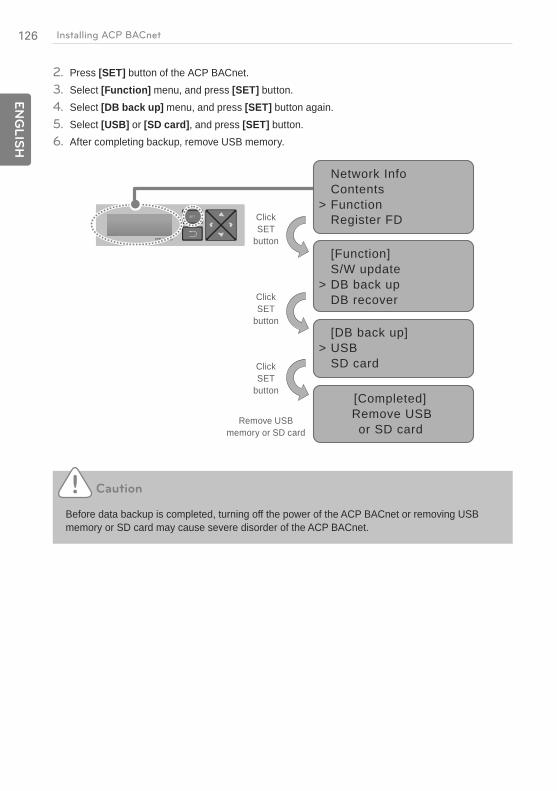
126
EN
GLIS
H
Installing ACP BACnet
2. Press [SET] button of the ACP BACnet.3. Select [Function] menu, and press [SET] button.4. Select [DB back up] menu, and press [SET] button again.5. Select [USB] or [SD card], and press [SET] button.6. After completing backup, remove USB memory.
Network InfoContentsFunctionRegister FD
>
[DB back up]USBSD card
>
[Function]S/W updateDB back upDB recover
>
[Completed]Remove USBor SD card
Click SET
button
Click SET
button
Click SET
button
Remove USB memory or SD card
Caution
Before data backup is completed, turning off the power of the ACP BACnet or removing USB memory or SD card may cause severe disorder of the ACP BACnet.

127E
NG
LIS
HInstalling ACP BACnet
Data recovery
If ACP BACnet data recovery is necessary, it must be carried out by the specialized service technician.
Data recovery can be done with USB memory or SD card.
Proceed in the following order.
1. Save the database file to recover in USB memory or SD card.
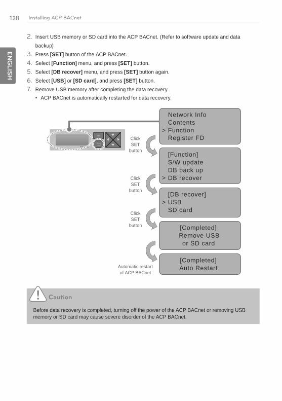
128
EN
GLIS
H
Installing ACP BACnet
2. Insert USB memory or SD card into the ACP BACnet. (Refer to software update and data backup)
3. Press [SET] button of the ACP BACnet.4. Select [Function] menu, and press [SET] button.5. Select [DB recover] menu, and press [SET] button again.6. Select [USB] or [SD card], and press [SET] button.7. Remove USB memory after completing the data recovery.
ACP BACnet is automatically restarted for data recovery.
Caution
Before data recovery is completed, turning off the power of the ACP BACnet or removing USB memory or SD card may cause severe disorder of the ACP BACnet.
Network InfoContentsFunctionRegister FD
>
[DB recover]USBSD card
>
[Function]S/W updateDB back upDB recover>
[Completed]Remove USBor SD card
[Completed]Auto Restart
Click SET
button
Click SET
button
Click SET
button
Automatic restart of ACP BACnet
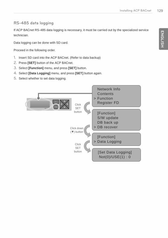
129E
NG
LIS
HInstalling ACP BACnet
RS-485 data logging
If ACP BACnet RS-485 data logging is necessary, it must be carried out by the specialized service technician.
Data logging can be done with SD card.
Proceed in the following order.
1. Insert SD card into the ACP BACnet. (Refer to data backup)2. Press [SET] button of the ACP BACnet.3. Select [Function] menu, and press [SET] button.4. Select [Data Logging] menu, and press [SET] button again.5. Select whether to set data logging.
Network InfoContentsFunctionRegister FD
>
[Function]Data Logging>
[Function]S/W updateDB back upDB recover>
[Set Data Logging]Not(0)/USE(1) : 0
Click SET
button
Click SET
button
Click down

130
EN
GLIS
H
Installing ACP BACnet
Register Foreign Device
1. In [Register FD]2. IP, PORT, TTL, and Activate of Foreign Device are displayed in the initial screen of [Register
FD]button.
3. To change the Foreign Device setting, locate the arrow on the corresponding setting position, and press [SET] button to enter the corresponding setting screen.
Example of IP setting
Network InfoContentsFunctionRegister FD>
[Set FD IP]192.168.000.000
[Register FD]IP 000.000.000PORT : 00000TTL : 00000ON : 0
>
Example of PORT setting
Network InfoContentsFunctionRegister FD>
[Set FD PORT]047808
[Register FD]IP 000.000.000PORT : 00000TTL : 00000ON : 0
>
Click SET
button
Click SET
button
Click SET
button
Click SET
button
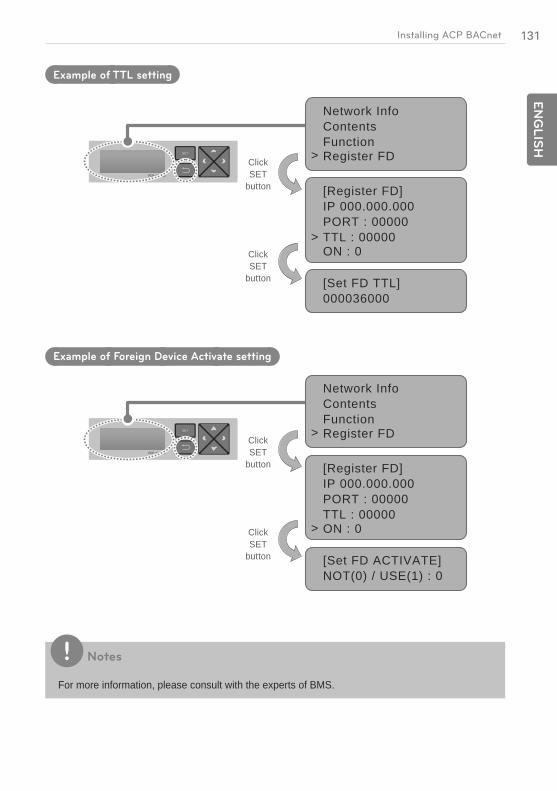
131E
NG
LIS
HInstalling ACP BACnet
Example of TTL setting
Network InfoContentsFunctionRegister FD>
[Set FD TTL]000036000
[Register FD]IP 000.000.000PORT : 00000TTL : 00000ON : 0
>
Example of Foreign Device Activate setting
Network InfoContentsFunctionRegister FD>
[Set FD ACTIVATE]NOT(0) / USE(1) : 0
[Register FD]IP 000.000.000PORT : 00000TTL : 00000ON : 0>
Notes
For more information, please consult with the experts of BMS.
Click SET
button
Click SET
button
Click SET
button
Click SET
button

EN
GLIS
H
MEMO

133E
NG
LIS
HLG's ACP BACnet Agreement
LG's ACP BACnet Agreement
JMT (Joint Matching Test)
This is necessary for every independent BMS.
The case where a JMT is not necessary is where previously a successful JMT has been carried out and the BMS system has not been updated by software or hardware changes. In the case that the BMS has updated their system by either changes, a following JMT will be required.
ACP BACnet Diagnosis
Use of LG's ACP BACnet setup-tool is for confirming the operation/state of connected A/C units & address ID's, prior to connection with the BMS system.
BMS Engineering
Creating of the Points. This is NOT to be done by LG since it is directly related to the BMS side. The BMS engineer is to carry out the engineering of the Point, however LG is responsible for providing the method of how the Points are calculated.
Commission
First step, only using LG's ACP BACnet, without connecting BMS. This is to be carried out by LG engineering staff with the use of the ACP BACnet set up tool.
Discrepancy of operation of Gateway by BMS
In the case that the BMS maker feels that the ACP BACnet is not functioning correctly via the BACnet Protocol, a test with the use of LG's ACP BACnet Client software can confirm this. (This test is generally not required)
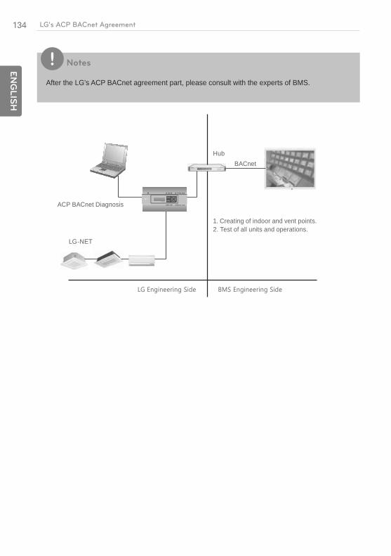
134
EN
GLIS
H
LG's ACP BACnet Agreement
Notes
After the LG's ACP BACnet agreement part, please consult with the experts of BMS.
PQNFB17C0
HubBACnet
LG-NET
ACP BACnet Diagnosis
1. Creating of indoor and vent points.2. Test of all units and operations.
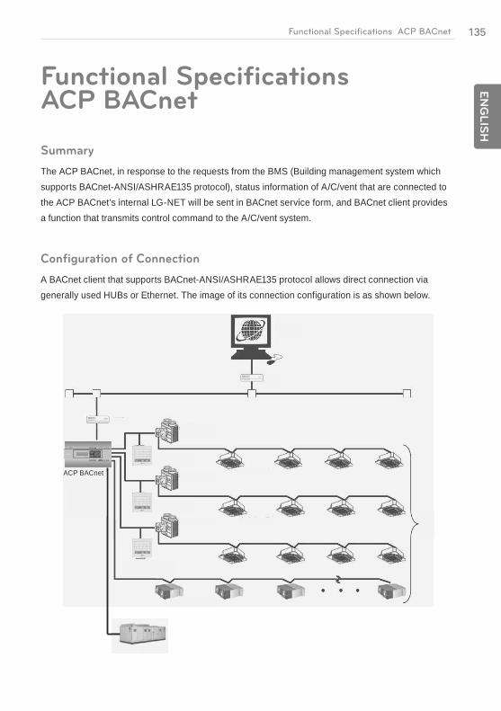
135E
NG
LIS
HFunctional Specifications ACP BACnet
Functional Specifications ACP BACnet
Summary
The ACP BACnet, in response to the requests from the BMS (Building management system which supports BACnet-ANSI/ASHRAE135 protocol), status information of A/C/vent that are connected to the ACP BACnet's internal LG-NET will be sent in BACnet service form, and BACnet client provides a function that transmits control command to the A/C/vent system.
Configuration of Connection
A BACnet client that supports BACnet-ANSI/ASHRAE135 protocol allows direct connection via generally used HUBs or Ethernet. The image of its connection configuration is as shown below.
PQNFB17C0
ACP BACnet
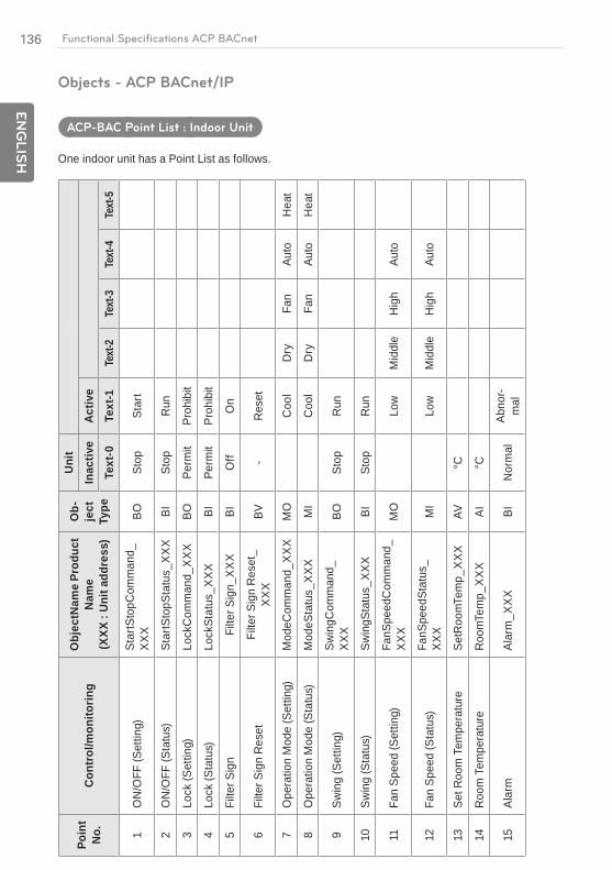
136
EN
GLIS
H
Functional Specifications ACP BACnet
Objects - ACP BACnet/IP
ACP-BAC Point List : Indoor Unit
One indoor unit has a Point List as follows.
Poin
t N
o.Co
ntro
l/mon
itorin
gO
bjec
tNam
e Pr
oduc
t N
ame
(XXX
: Un
it ad
dres
s)
Ob-
ject
Ty
pe
Uni
tIn
activ
e Ac
tive
Text
-0
Text
-1
Text
-2
Text
-3
Text
-4
Text
-5
1O
N/O
FF (S
ettin
g)
Star
tSto
pCom
man
d_X
XX
BO
Stop
St
art
2O
N/O
FF (S
tatu
s)
Star
tSto
pSta
tus_
XX
X BI
St
op
Run
3Lo
ck (S
ettin
g)
Lock
Com
man
d_X
XX
BO
Perm
it Pr
ohib
it
4Lo
ck (S
tatu
s)
Lock
Stat
us_X
XX
BI
Perm
it Pr
ohib
it
5Fi
lter S
ign
Filte
r Sig
n_X
XX
BI
Off
On
6Fi
lter S
ign
Res
et
Filte
r Sig
n R
eset
_X
XX
BV
- R
eset
7O
pera
tion
Mod
e (S
ettin
g)
Mod
eCom
man
d_X
XX
MO
C
ool
Dry
Fa
n Au
to
Hea
t
8O
pera
tion
Mod
e (S
tatu
s)
Mod
eSta
tus_
XX
X M
I C
ool
Dry
Fa
n Au
to
Hea
t
Swin
g (S
ettin
g)
Swin
gCom
man
d_X
XX
BO
Stop
R
un
10Sw
ing
(Sta
tus)
Sw
ingS
tatu
s_X
XX
BI
Stop
R
un
11Fa
n Sp
eed
(Set
ting)
Fa
nSpe
edC
omm
and_
XX
X M
O
Low
M
iddl
e H
igh
Auto
12Fa
n Sp
eed
(Sta
tus)
Fa
nSpe
edSt
atus
_X
XX
MI
Low
M
iddl
e H
igh
Auto
13Se
t Roo
m T
empe
ratu
re
SetR
oom
Tem
p_X
XX
AV
°C
14R
oom
Tem
pera
ture
R
oom
Tem
p_X
XX
AI
°C
15Al
arm
Al
arm
_XX
X BI
N
orm
al
Abno
r-m
al
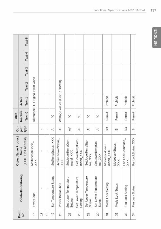
137E
NG
LIS
HFunctional Specifications ACP BACnet
Poin
t N
o.Co
ntro
l/mon
itorin
gO
bjec
tNam
e Pr
oduc
t N
ame
(XXX
: Un
it ad
dres
s)
Ob-
ject
Ty
pe
Uni
tIn
activ
e Ac
tive
Text
-0
Text
-1
Text
-2
Text
-3
Text
-4
Text
-5
16Er
ror C
ode
Mal
func
tionC
ode_
XX
X R
efer
ence
LG
Orig
inal
Err
or C
ode
17-
- -
18-
- -
Set T
empe
ratu
re S
tatu
s Se
tTem
pSta
tus_
XX
X AI
°C
20Po
wer
Dis
tribu
tion
Accu
mPo
wer
Stat
us_
XX
X AI
W
atta
ge v
alue
s (U
nit :
100
Wat
t)
27Se
t Upp
er T
empe
ratu
re
Setti
ng
SetU
pper
Tem
pCom
-m
and_
XX
X AV
°C
28Se
t Low
er T
empe
ratu
re
Setti
ng
SetL
ower
Tem
pCom
-m
and_
XX
X AI
°C
Set U
pper
Tem
pera
ture
St
atus
Se
tUpp
erTe
mpS
ta-
tus_
XX
X AI
°C
30Se
t Low
er T
empe
ratu
re
Stat
us
SetL
ower
Tem
pSta
-tu
s_X
XX
AI
°C
31M
ode
Lock
Set
ting
Mod
eLoc
kCom
-m
and_
XX
X BO
Pe
rmit
Proh
ibit
32M
ode
Lock
Sta
tus
Mod
eLoc
kSta
tus_
XX
X BI
Pe
rmit
Proh
ibit
33Fa
n Lo
ck S
ettin
g Fa
n Lo
ckC
omm
and_
XX
X BO
Pe
rmit
Proh
ibit
34Fa
n Lo
ck S
tatu
s Fa
nLoc
kSta
tus_
XX
X BI
Pe
rmit
Proh
ibit
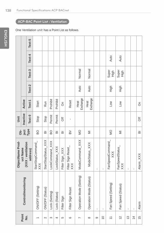
138
EN
GLIS
H
Functional Specifications ACP BACnet
ACP-BAC Point List : Ventilation
One Ventilation has a Point List as follows.
Poin
t N
o.Co
ntro
l/mon
itorin
g
Obj
ectN
ame
Prod
-uc
t Nam
e (X
XX :
vent
ilatio
n ad
dres
s)
Ob-
ject
Ty
pe
Uni
tIn
activ
e Ac
tive
Text
-0
Text
-1
Text
-2
Text
-3
Text
-4
Text
-5
1O
N/O
FF (S
ettin
g)
Star
tSto
pCom
man
d_X
XX
BO
Stop
St
art
2O
N/O
FF (S
tatu
s)
Star
tSto
pSta
tus_
XX
X BI
St
op
Run
3Lo
ck (S
ettin
g)
Lock
Com
man
d_X
XX
BO
Perm
it Pr
ohib
it
4Lo
ck (S
tatu
s)
Lock
Stat
us_X
XX
BI
Perm
it Pr
ohib
it
5Fi
lter S
ign
Filte
r Sig
n_X
XX
BI
Off
On
6Fi
lter S
ign
Res
et
Filte
r Sig
n R
eset
_X
XX
BV
- R
eset
7O
pera
tion
Mod
e (S
ettin
g)
Mod
eCom
man
d_X
XX
MO
H
eat
Exch
ange
Auto
N
orm
al
8O
pera
tion
Mod
e (S
tatu
s)
Mod
eSta
tus_
XX
X M
I H
eat
Exch
ange
Auto
N
orm
al
- -
10-
-
11Fa
n Sp
eed
(Set
ting)
Fa
nSpe
edC
omm
and_
XX
X M
O
Low
H
igh
Supe
r H
igh
Auto
12Fa
n Sp
eed
(Sta
tus)
Fa
nSpe
edSt
atus
_X
XX
MI
Low
H
igh
Supe
r H
igh
Auto
13-
-
14-
-
15Al
arm
Al
arm
_XX
X BI
O
ff O
n

139E
NG
LIS
HFunctional Specifications ACP BACnet
Poin
t N
o.Co
ntro
l/mon
itorin
g
Obj
ectN
ame
Prod
-uc
t Nam
e (X
XX :
vent
ilatio
n ad
dres
s)
Ob-
ject
Ty
pe
Uni
tIn
activ
e Ac
tive
Text
-0
Text
-1
Text
-2
Text
-3
Text
-4
Text
-5
16Er
ror C
ode
Mal
func
tionC
ode_
XX
X AI
R
efer
ence
LG
Orig
inal
Err
or C
ode
17U
ser M
ode(
Setti
ng)
Use
rMod
eCom
-m
and_
XX
XM
O
Qui
ck
Fres
h En
ergy
Sa
ving
H
eate
r
18U
ser M
ode(
Stat
us)
Use
rMod
eSta
tus_
XX
X M
I Q
uick
Fr
esh
Ener
gy
Savi
ng
Hea
ter
°C
20-
- -
21AC
Ope
ratio
n M
ode
(set
ting)
H
rvM
odeC
omm
and_
XX
X M
O
Coo
l Au
to
Hea
t
22AC
Ope
ratio
n M
ode
(sta
tus)
H
rvM
odeS
tatu
s_X
XX
MI
Coo
l Au
to
Hea
t
23AC
ON
/OFF
(set
ting)
H
rvSt
artS
topC
om-
man
d_X
XX
BO
Stop
R
un
24AC
ON
/OFF
(sta
tus)
H
rvSt
artS
topS
tatu
s_X
XX
BI
Stop
R
un
25AC
Hum
idify
(set
ting)
H
rvH
umid
ifyC
om-
man
d_X
XX
BO
Off
On
26AC
Hum
idify
(sta
tus)
H
rvH
umid
ifySt
atus
_X
XX
BI
Off
On

140
EN
GLIS
H
Functional Specifications ACP BACnet
ACP-BAC Point List : AHUPo
int
No.
Cont
rol/
mon
itorin
gO
bjec
tNam
e Pr
oduc
t Nam
e (X
XX :
AH
U ad
dres
s)
Ob-
ject
Ty
pe
Uni
tIn
activ
e Ac
tive
Text
-0
Text
-1
Text
-2
Text
-3
Text
-4
Text
-5
ON
/OFF
(Set
ting)
St
artS
topC
omm
and_
XX
X BO
St
op
Run
ON
/OFF
(Sta
tus)
St
artS
topS
tatu
s_X
XX
BI
Stop
R
un
Lock
(Set
ting)
Lo
ckC
omm
and_
XX
X BO
Pe
rmit
Proh
ibit
Lock
(Sta
tus)
Lo
ckSt
atus
_XX
X BI
Pe
rmit
Proh
ibit
Filte
r Sig
n Fi
lter S
ign_
XX
X BI
O
ff O
n Fi
lter S
ign
Res
et
Filte
r Sig
n R
eset
_XX
X BV
-
Res
et
Ope
ratio
n M
ode
(Set
ting)
M
odeC
omm
and_
XX
X M
O
Coo
l D
ry
Fan
Hea
t
Ope
ratio
n M
ode
(Sta
tus)
M
odeS
tatu
s_X
XX
MI
Coo
l D
ry
Fan
Hea
t
- -
- -
- -
- -
Set R
oom
Te
mpe
ratu
re
SetR
oom
Tem
p_X
XX
AV
°C
Roo
m
Tem
pera
ture
R
oom
Tem
p_X
XX
AI
°C
Alar
m
Alar
m_X
XX
BI
Nor
mal
Ab
nor-
mal
Er
ror C
ode
Mal
func
tionC
ode_
XX
X AI
R
efer
ence
LG
Orig
inal
Err
or C
ode
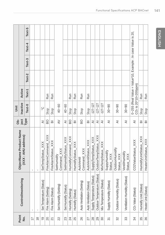
141E
NG
LIS
HFunctional Specifications ACP BACnet
Poin
t N
o.C
ontr
ol/m
onito
ring
Obj
ectN
ame
Prod
uct N
ame
(XXX
: A
HU
addr
ess)
Ob-
ject
Ty
pe
Uni
tIn
activ
e Ac
tive
Text
-0
Text
-1
Text
-2
Text
-3
Text
-4
Text
-5
17-
-18
--
Set T
empe
ratu
re (S
tatu
s)Se
tTem
pSta
tus_
XX
XAI
°C20
Fire
Ala
rm (S
ettin
g)Fi
reAl
arm
Com
man
d_X
XX
BOR
un21
Fire
Ala
rm (S
tatu
s)Fi
reAl
arm
Stat
us_X
XX
BIR
un
22Se
t Hum
idify
(Set
ting)
SetH
umid
ify
Com
man
d_X
XX
AV40
~60
23Se
t Hum
idify
(Sta
tus)
SetH
umid
ifySt
atus
_XX
XAI
40~6
024
Hum
idify
(Set
ting)
Hum
idify
Com
man
d_X
XX
BOR
un25
Hum
idify
(Sta
tus)
Hum
idify
Stat
us_X
XX
BIR
un
26Au
to V
entila
tion
(Set
ting)
Auto
Vent
il C
omm
and_
XX
XBO
Run
27Au
to V
entila
tion
(Sta
tus)
Auto
Vent
ilSta
tus_
XX
XBI
Run
28Su
pply
Tem
pera
ture
(Sta
tus)
Supp
lyTem
pSta
tus_
XX
XAI
-127
~127
Out
door
Tem
pera
ture
(Sta
tus)
Out
door
Tem
pSta
tus_
XX
XAI
-127
~127
30M
ix Te
mpe
ratu
re (S
tatu
s)M
ixTem
pSta
tus_
XX
XAI
-127
~127
31Su
pply
Hum
idity
(Sta
tus)
Supp
yHum
idify
St
atus
_XX
XAI
32O
utdo
or H
umid
ity (S
tatu
s)O
utdo
orH
umid
ify
Stat
us_X
XX
AI
33Ve
ntila
tion
Hum
idity
(Sta
tus)
Vent
ilHum
idify
St
atus
_XX
XAI
34CO
2 Val
ue (S
tatu
s)C
O2V
alue
Stat
us_X
XX
AI0~
255
(Rea
l Val
ue =
Val
ue*1
0, E
xam
ple
: In
case
Val
ue is
20,
C
O2 i
s 20
*10=
200p
pm)
35Hu
mid
ify U
nit (
Stat
us)
Hum
idify
Uni
tSta
tus_
XX
XBI
Run
36He
ater
Uni
t (St
atus
)H
eate
rUni
tSta
tus_
XX
XBI
Run
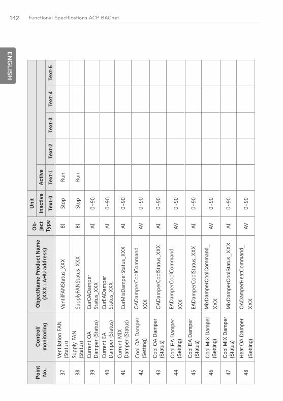
142
EN
GLIS
H
Functional Specifications ACP BACnet
Poin
t N
o.Co
ntro
l/m
onito
ring
Obj
ectN
ame
Prod
uct N
ame
(XXX
: A
HU
addr
ess)
Ob-
ject
Ty
pe
Uni
tIn
activ
e Ac
tive
Text
-0
Text
-1
Text
-2
Text
-3
Text
-4
Text
-5
Coo
l OA
Dam
per
(Sta
tus)
Coo
l EA
Dam
per
(Set
ting)
Coo
l EA
Dam
per
(Sta
tus)
Coo
l MIX
Dam
per
(Set
ting)
Mix
Dam
perC
oolC
omm
and_
XX
X
Coo
l MIX
Dam
per
(Sta
tus)
Mix
Dam
perC
oolS
tatu
s_X
XX
Hea
t OA
Dam
per
(Set
ting)
OAD
ampe
rHea
tCom
man
d_X
XX
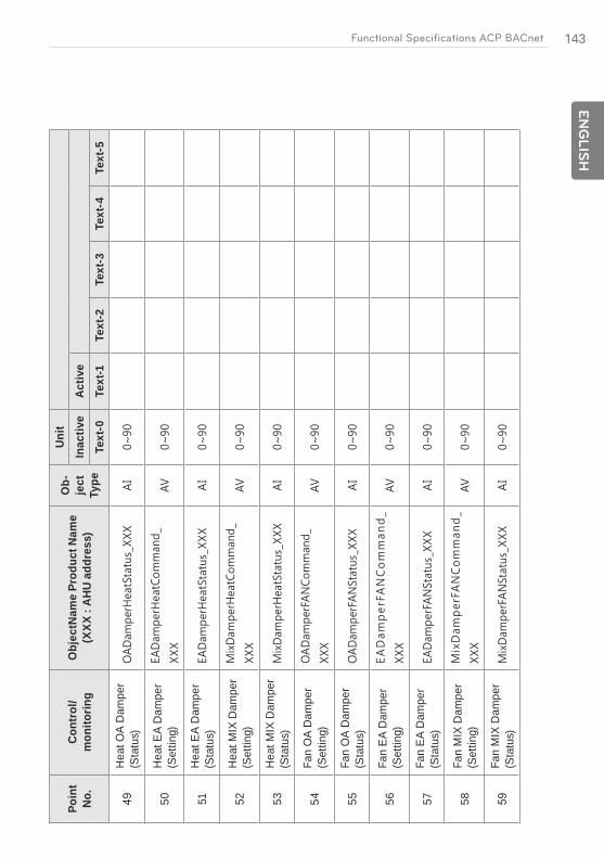
143E
NG
LIS
HFunctional Specifications ACP BACnet
Poin
t N
o.Co
ntro
l/m
onito
ring
Obj
ectN
ame
Prod
uct N
ame
(XXX
: A
HU
addr
ess)
Ob-
ject
Ty
pe
Uni
tIn
activ
e Ac
tive
Text
-0
Text
-1
Text
-2
Text
-3
Text
-4
Text
-5
Hea
t OA
Dam
per
(Sta
tus)
50
Hea
t EA
Dam
per
(Set
ting)
51
Hea
t EA
Dam
per
(Sta
tus)
52
Hea
t MIX
Dam
per
(Set
ting)
53
Hea
t MIX
Dam
per
(Sta
tus)
54
Fan
OA
Dam
per
(Set
ting)
55
Fan
OA
Dam
per
(Sta
tus)
56
Fan
EA
Dam
per
(Set
ting)
57
Fan
EA
Dam
per
(Sta
tus)
58
Fan
MIX
Dam
per
(Set
ting)
Fan
MIX
Dam
per
(Sta
tus)

144
ENGLIS
H
Functional Specifications ACP BACnet
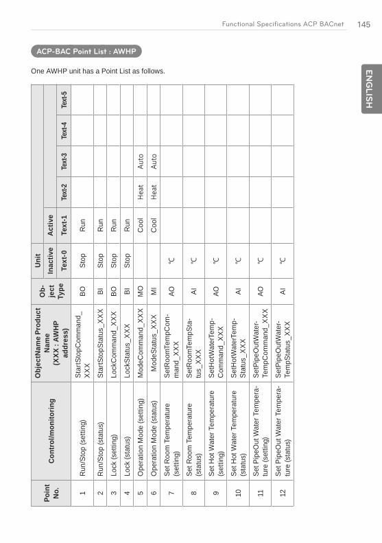
145E
NG
LIS
HFunctional Specifications ACP BACnet
ACP-BAC Point List : AWHP
One AWHP unit has a Point List as follows.
Poin
t N
o.Co
ntro
l/mon
itorin
g
Obj
ectN
ame
Prod
uct
Nam
e (X
XX :
AWH
P ad
dres
s)
Ob-
ject
Ty
pe
Uni
tIn
activ
e Ac
tive
Text
-0
Text
-1
Text
-2
Text
-3
Text
-4
Text
-5
1R
un/S
top
(set
ting)
Star
tSto
pCom
man
d_X
XX
BOSt
opR
un
2R
un/S
top
(sta
tus)
Star
tSto
pSta
tus_
XX
XBI
Stop
Run
3Lo
ck (s
ettin
g)Lo
ckC
omm
and_
XX
XBO
Stop
Run
4Lo
ck (s
tatu
s)Lo
ckSt
atus
_XX
XBI
Stop
Run
5O
pera
tion
Mod
e (s
ettin
g)M
odeC
omm
and_
XX
XM
OC
ool
6O
pera
tion
Mod
e (s
tatu
s)M
odeS
tatu
s_X
XX
MI
Coo
l
7Se
t Roo
m T
empe
ratu
re
(set
ting)
SetR
oom
Tem
pCom
-m
and_
XX
XAO
8Se
t Roo
m T
empe
ratu
re
(sta
tus)
SetR
oom
Tem
pSta
-tu
s_X
XX
AI
Set H
ot W
ater
Tem
pera
ture
(s
ettin
g)Se
tHot
Wat
erTe
mp-
Com
man
d_X
XX
AO
10Se
t Hot
Wat
er T
empe
ratu
re
(sta
tus)
SetH
otW
ater
Tem
p-St
atus
_XX
XAI
11Se
t Pip
eOut
Wat
er T
empe
ra-
ture
(set
ting)
SetP
ipeO
utW
ater
-Te
mpC
omm
and_
XX
XAO
12Se
t Pip
eOut
Wat
er T
empe
ra-
ture
(sta
tus)
SetP
ipeO
utW
ater
-Te
mpS
tatu
s_X
XX
AI

146
EN
GLIS
H
Functional Specifications ACP BACnet
Poin
t N
o.Co
ntro
l/mon
itorin
g
Obj
ectN
ame
Prod
uct
Nam
e (X
XX :
AWH
P ad
dres
s)
Ob-
ject
Ty
pe
Uni
tIn
activ
e Ac
tive
Text
-0
Text
-1
Text
-2
Text
-3
Text
-4
Text
-5
13Se
tting
Tem
pera
ture
Ref
er-
ence
(Air/
Wat
er)
AirW
ater
Flag
_XX
XBI
Air
Wat
er
14H
ot W
ater
Onl
y M
ode
Hot
Wat
erO
nlyF
lag_
XX
XBI
Nor
mal
Hot
W
ater
O
nly
15C
urre
nt R
oom
Tem
pera
ture
Roo
mTe
mp_
XX
XAI
16Al
arm
Eve
ntAl
arm
_XX
XBI
No
erro
rEr
ror
17M
alfu
nctio
n C
ode
Mal
func
tionC
ode_
XX
XAI
Ref
eren
ce L
G O
rigin
al E
rror
Cod
e
18H
otW
ater
On/
Off
(set
ting)
Hot
Wat
erC
omm
and_
XX
XBO
Hot
Wat
er O
n/O
ff (s
tatu
s)H
otW
ater
Stat
us_X
XX
BI
20Pi
pe In
let T
empe
ratu
re
Stat
usPi
peIn
Tem
pSta
-tu
s_X
XX
AI
21W
ater
Tan
k Te
mpe
ratu
re
Stat
usTa
nkTe
mpS
tatu
s_X
XX
AI
22So
lar T
empe
ratu
re S
tatu
sSo
larT
empS
tatu
s_X
XX
AI
23Pi
pe O
utle
t Tem
pera
ture
St
atus
Pipe
Out
Tem
pSta
-tu
s_X
XX
AI
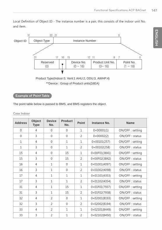
147E
NG
LIS
HFunctional Specifications ACP BACnet
Object ID Object Type
Reserved
Product Type(Indoor:0, Vent:1 AHU:2, ODU:3, AWHP:4) **Device : Group of Product units(16EA)
Device No. Product Unit No. Point No.
Instance Number
Example of Point Table
The point table below is passed to BMS, and BMS registers the object.
Case Indoor
Address Object Type
Device No.
Product No. Point Instance No. Name

148
EN
GLIS
H
Functional Specifications ACP BACnet
Address Object Type
Device No.
Product No. Point Instance No. Name
Address Object Type
Device No.
Product No. Point Instance No. Name
Case AHU
Address Object Type
Device No.
Product No. Point Instance No. Name
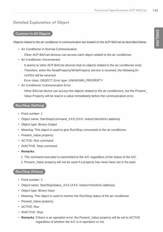
149E
NG
LIS
HFunctional Specifications ACP BACnet
Detailed Explanation of Object
Common to All Objects
Objects related to the air conditioner in communication are treated on the ACP BACnet as described below.
Air Conditioner in Normal Communication
- Other ACP BACnet devices can access each object related to the air conditioner.Air Conditioner Unconnected
- It seems to other ACP BACnet devices that no objects related to the air conditioner exist. - Therefore, when the ReadProperty/WriteProperty service is received, the following Er-
rorPDU will be returned. - Error class: OBJECT; Error type: UNKNOWN_PROPERTYAir Conditioner Communication Error
- Other BACnet device can access the objects related to the air conditioners, but the Present_Value Property will be read in a value immediately before the communication error.
Run/Stop (Setting)
Point number: 1
Object name: StartStopCommand_XXX (XXX: Indoor/Vent/AHU address)
Object type: Binary Output
Meaning: This object is used to give Run/Stop commands to the air conditioner.
Present_Value property:
ACTIVE: Run command
INACTIVE: Stop command
Remarks:
1. The command executed is transmitted to the A/C regardless of the status of the A/C.2. Present_Value property will not be used if a property has never been set in the past.
Run/Stop (Status)
Point number: 2
Object name: StartStopStatus_XXX (XXX: Indoor/Vent/AHU address)
Object type: Binary Input
Meaning: This object is used to monitor the Run/Stop status of the air conditioner.
Present_Value property:
ACTIVE: Run
INACTIVE: Stop
Remarks: If there is an operation error, the Present_Value property will be set to ACTIVE regardless of whether the A/C is in operation or not.

150
EN
GLIS
H
Functional Specifications ACP BACnet
Lock (Setting)
Point number: 3
Object name: LockCommand_XXX (XXX: Indoor/Vent/AHU address)
Object type: Binary Output
Meaning: This object is used to set the Lock of the A/C's control authority.
Present_Value property:
ACTIVE: Lock (Restricted)
INACTIVE: Unlock (Not restricted)
Lock (Status)
Point number: 4
Object name: LockStatus_XXX (XXX: Indoor/Vent/AHU address)
Object type: Binary Input
Meaning: This object is used to monitor the Lock of the A/C's control authority.
Present_Value property:
ACTIVE: Lock (Restricted)
INACTIVE: Unlock (Not restricted)
Filter Sign
Point number: 5
Object name: FilterSign_XXX (XXX: Vent/AHU address)
Object type: Binary Input
Meaning: This object is used to monitor the status of the filters for vent.
Present_Value property:
ACTIVE: Filter sign information is turned ON.
INACTIVE: Filter sign information is OFF.
Remarks: This object supports the Intrinsic Reporting function. When the Present_Value property changes, the corresponding Event will be transmitted if the Event has been registered.

151E
NG
LIS
HFunctional Specifications ACP BACnet
Filter Sign Reset
Point number: 6
Object name: FilterSignReset_XXX (XXX: Vent/AHU address)
Object type: Binary Value
Meaning: This object is used to reset the vent s limit indication.
Present_Value property:
INACTIVE: Filter indication information is reset.
Remarks:
1. During a read operation of the Present_Value property, the Fliter Limit Sign Reset will be always the same value as the Filter Limit Sign object.
2. Only if INACTIVE is written to the Present_Value property during a write operation, the filter sign information resets ON signs and nothing will be executed even if ACTIVE is written.
3. This object supports the Intrinsic Reporting function. When the Present_Value property changes, the corresponding Event will be transmitted if the Event has been registered.
Operation Mode (Setting)
Point number: 7
Object name: ModeCommand_XXX (XXX: Indoor/Vent/AHU address)
Object type: Multistate Output
Meaning: This object is used to set the operation modes of the air conditioner.
Present_Value property:
1 : Cool HEX
2 : Dry Auto
3 : Fan Normal
4 : Auto -
5 : Heat -
Remarks:
1. The Present_Value property will be set to "1: Cool" as the default value if property has never been set in the past.
2. The air conditioner will ignore the command to an object that does not have right to select operation mode. Therefore, the controlled/monitored system must not use this object for the air conditioner without the right to select operation mode.

152
EN
GLIS
H
Functional Specifications ACP BACnet
Operation Mode (Status)
Point number: 8
Object name: ModeStatus_XXX (XXX: Indoor/Vent/AHU address)
Object type: Multistate Input
Meaning: This object is used to monitor the operation modes of the air conditioner.
Present_Value property:
1 : Cool HEX
2 : Dry Auto
3 : Fan Normal
4 : Auto -
5 : Heat -
Swing (Setting)
Object name: SwingCommand_XXX (XXX: Indoor address)
Object type: Binary Output
Meaning: This object is to set the air direction of the indoor unit.
Present_Value property:
ACTIVE: Run
INACTIVE: Stop
Swing (Status)
Point number: 10
Object name: SwingStatus_XXX (XXX: Indoor address)
Object type: Binary Input
Meaning: This object is to monitor the air direction of the A/C.
Present_Value property:
ACTIVE: Swing_On
INACTIVE: Swing_Off
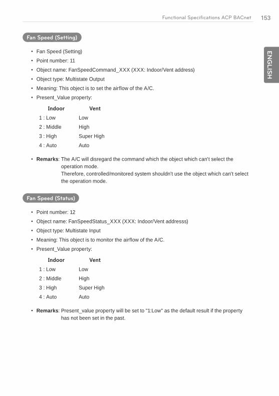
153E
NG
LIS
HFunctional Specifications ACP BACnet
Fan Speed (Setting)
Fan Speed (Setting)
Point number: 11
Object name: FanSpeedCommand_XXX (XXX: Indoor/Vent address)
Object type: Multistate Output
Meaning: This object is to set the airflow of the A/C.
Present_Value property:
1 : Low Low
2 : Middle High
3 : High Super High
4 : Auto Auto
Remarks: The A/C will disregard the command which the object which can't select the operation mode. Therefore, controlled/monitored system shouldn't use the object which can't select the operation mode.
Fan Speed (Status)
Point number: 12
Object name: FanSpeedStatus_XXX (XXX: Indoor/Vent addresss)
Object type: Multistate Input
Meaning: This object is to monitor the airflow of the A/C.
Present_Value property:
1 : Low Low
2 : Middle High
3 : High Super High
4 : Auto Auto
Remarks: Present_value property will be set to "1:Low" as the default result if the property has not been set in the past.
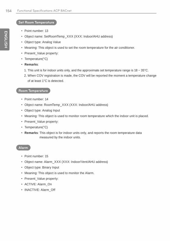
154
EN
GLIS
H
Functional Specifications ACP BACnet
Set Room Temperature
Point number: 13
Object name: SetRoomTemp_XXX (XXX: Indoor/AHU address)
Object type: Analog Value
Meaning: This object is used to set the room temperature for the air conditioner.
Present_Value property:
Temperature(°C)
Remarks:
1. This unit is for indoor units only, and the approximate set temperature range is 18 ~ 35°C.2. When COV registration is made, the COV will be reported the moment a temperature change
of at least 1°C is detected.
Room Temperature
Point number: 14
Object name: RoomTemp_XXX (XXX: Indoor/AHU address)
Object type: Analog Input
Meaning: This object is used to monitor room temperature which the indoor unit is placed.
Present_Value property:
Temperature(°C)
Remarks: This object is for indoor units only, and reports the room temperature data measured by the indoor units.
Alarm
Point number: 15
Object name: Alarm_XXX (XXX: Indoor/Vent/AHU address)
Object type: Binary Input
Meaning: This object is used to monitor the Alarm.
Present_Value property:
ACTIVE: Alarm_On
INACTIVE: Alarm_Off
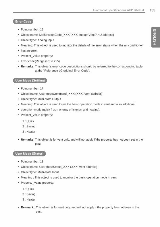
155E
NG
LIS
HFunctional Specifications ACP BACnet
Error Code
Point number: 16
Object name: MalfunctionCode_XXX (XXX: Indoor/Vent/AHU address)
Object type: Analog Input
Meaning: This object is used to monitor the details of the error status when the air conditioner
has an error.
Present_Value property:
Error code(Range is 1 to 255)
Remarks: This object's error code descriptions should be referred to the corresponding table at the "Reference LG original Error Code".
User Mode (Setting)
Point number: 17
Object name: UserModeCommand_XXX (XXX: Vent address)
Object type: Multi-state Output
Meaning: This object is used to set the basic operation mode in vent and also additional
operation mode (quick fresh, energy efficiency, and heating).
Present_Value property:
1 : Quick
2 : Saving
3 : Heater
Remarks: This object is for vent only, and will not apply if the property has not been set in the past.
User Mode (Status)
Point number: 18
Object name: UserModeStatus_XXX (XXX: Vent address)
Object type: Multi-state Input
Meaning : This object is used to monitor the basic operation mode in vent
Property_Value property:
1 : Quick
2 : Saving
3 : Heater
Reamark : This object is for vent only, and will not apply if the property has not been in the past.
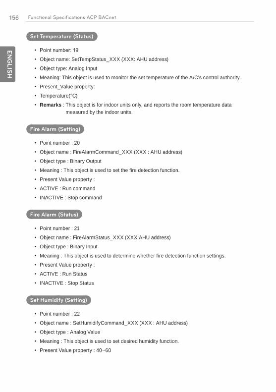
156
EN
GLIS
H
Functional Specifications ACP BACnet
Set Temperature (Status)
Object name: SetTempStatus_XXX (XXX: AHU address)
Object type: Analog Input
Meaning: This object is used to monitor the set temperature of the A/C's control authority.
Present_Value property:
Temperature(°C)
Remarks : This object is for indoor units only, and reports the room temperature data measured by the indoor units.
Fire Alarm (Setting)
Point number : 20
Object name : FireAlarmCommand_XXX (XXX : AHU address)
Object type : Binary Output
Meaning : This object is used to set the fire detection function.
Present Value property :
ACTIVE : Run command
INACTIVE : Stop command
Fire Alarm (Status)
Point number : 21
Object name : FireAlarmStatus_XXX (XXX:AHU address)
Object type : Binary Input
Meaning : This object is used to determine whether fire detection function settings.
Present Value property :
ACTIVE : Run Status
INACTIVE : Stop Status
Set Humidify (Setting)
Point number : 22
Object name : SetHumidifyCommand_XXX (XXX : AHU address)
Object type : Analog Value
Meaning : This object is used to set desired humidity function.
Present Value property : 40~60
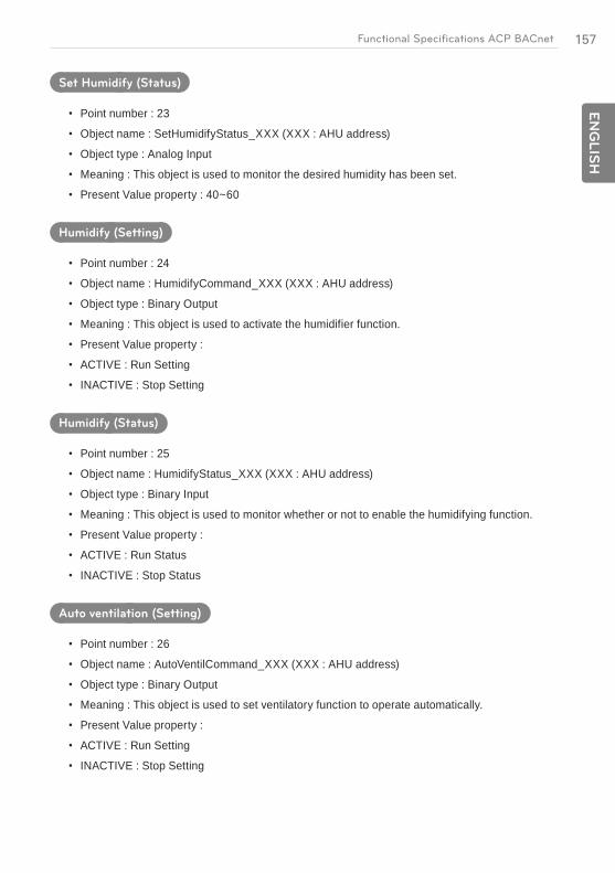
157E
NG
LIS
HFunctional Specifications ACP BACnet
Set Humidify (Status)
Point number : 23
Object name : SetHumidifyStatus_XXX (XXX : AHU address)
Object type : Analog Input
Meaning : This object is used to monitor the desired humidity has been set.
Present Value property : 40~60
Humidify (Setting)
Point number : 24
Object name : HumidifyCommand_XXX (XXX : AHU address)
Object type : Binary Output
Meaning : This object is used to activate the humidifier function.
Present Value property :
ACTIVE : Run Setting
INACTIVE : Stop Setting
Humidify (Status)
Point number : 25
Object name : HumidifyStatus_XXX (XXX : AHU address)
Object type : Binary Input
Meaning : This object is used to monitor whether or not to enable the humidifying function.
Present Value property :
ACTIVE : Run Status
INACTIVE : Stop Status
Auto ventilation (Setting)
Point number : 26
Object name : AutoVentilCommand_XXX (XXX : AHU address)
Object type : Binary Output
Meaning : This object is used to set ventilatory function to operate automatically.
Present Value property :
ACTIVE : Run Setting
INACTIVE : Stop Setting

158
EN
GLIS
H
Functional Specifications ACP BACnet
Auto ventilation (Status)
Point number : 27
Object name : AutoVentilStatus_XXX (XXX : AHU address)
Object type : Binary Input
Meaning : This object is used to monitor the presence or absence of the operation of the automatic ventilatory function.
Present Value property :
ACTIVE : Run Status
INACTIVE : Stop Status
Supply temperature (Status)
Point number : 28
Object name : SupplyTempStatus_XXX (XXX : AHU address)
Object type : Analog Value
Meaning : This object is used to monitor the temperature of the air to be supplied.
Present Value property : -127~127
Outdoor temperature (Status)
Object name : OutdoorTempStatus_XXX (XXX : AHU address)
Object type : Analog Value
Meaning : This object is used to monitor the temperature of the outside air.
Present Value property : -127~127
Mix Temperature (Status)
Point number : 30
Object name : MixTempStatus_XXX (XXX : AHU address)
Object type : Analog Value
Meaning : This object is used to monitor the temperature of the air that is mixed.
Present Value property : -127~127
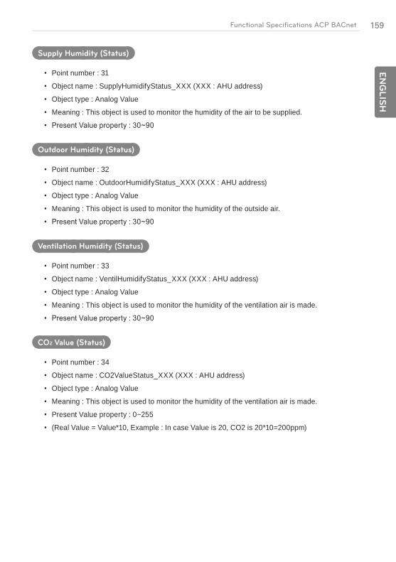
159E
NG
LIS
HFunctional Specifications ACP BACnet
Supply Humidity (Status)
Point number : 31
Object name : SupplyHumidifyStatus_XXX (XXX : AHU address)
Object type : Analog Value
Meaning : This object is used to monitor the humidity of the air to be supplied.
Outdoor Humidity (Status)
Point number : 32
Object name : OutdoorHumidifyStatus_XXX (XXX : AHU address)
Object type : Analog Value
Meaning : This object is used to monitor the humidity of the outside air.
Ventilation Humidity (Status)
Point number : 33
Object name : VentilHumidifyStatus_XXX (XXX : AHU address)
Object type : Analog Value
Meaning : This object is used to monitor the humidity of the ventilation air is made.
CO2 Value (Status)
Point number : 34
Object name : CO2ValueStatus_XXX (XXX : AHU address)
Object type : Analog Value
Meaning : This object is used to monitor the humidity of the ventilation air is made.
Present Value property : 0~255
(Real Value = Value*10, Example : In case Value is 20, CO2 is 20*10=200ppm)
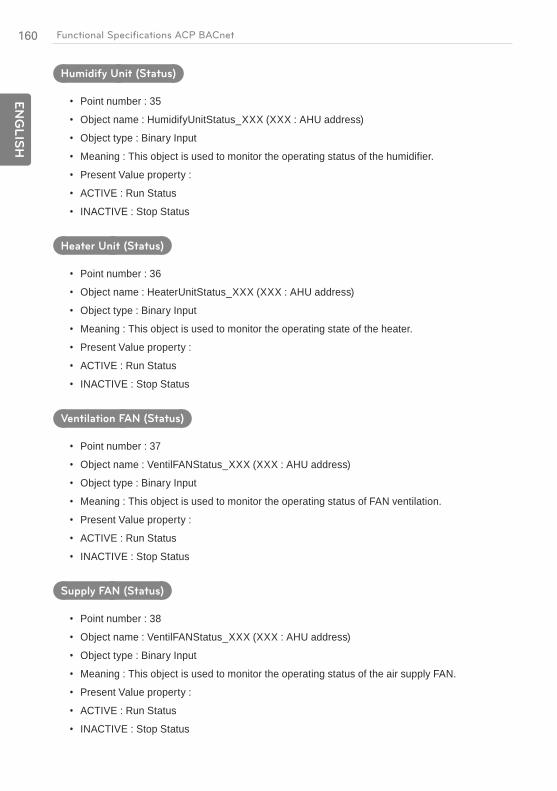
160
EN
GLIS
H
Functional Specifications ACP BACnet
Humidify Unit (Status)
Point number : 35
Object name : HumidifyUnitStatus_XXX (XXX : AHU address)
Object type : Binary Input
Meaning : This object is used to monitor the operating status of the humidifier.
Present Value property :
ACTIVE : Run Status
INACTIVE : Stop Status
Heater Unit (Status)
Point number : 36
Object name : HeaterUnitStatus_XXX (XXX : AHU address)
Object type : Binary Input
Meaning : This object is used to monitor the operating state of the heater.
Present Value property :
ACTIVE : Run Status
INACTIVE : Stop Status
Ventilation FAN (Status)
Point number : 37
Object name : VentilFANStatus_XXX (XXX : AHU address)
Object type : Binary Input
Meaning : This object is used to monitor the operating status of FAN ventilation.
Present Value property :
ACTIVE : Run Status
INACTIVE : Stop Status
Supply FAN (Status)
Point number : 38
Object name : VentilFANStatus_XXX (XXX : AHU address)
Object type : Binary Input
Meaning : This object is used to monitor the operating status of the air supply FAN.
Present Value property :
ACTIVE : Run Status
INACTIVE : Stop Status

161E
NG
LIS
HFunctional Specifications ACP BACnet
Current OA Damper (Status)
Object name : CurOADamperStatus_XXX (XXX : AHU address)
Object type : Analog Input
Meaning : This object is used to monitor the current opening degree of OA damper.
Current EA Damper (Status)
Point number : 40
Object name : CurEADamperStatus_XXX (XXX : AHU address)
Object type : Analog Input
Meaning : This object is used to monitor the current opening degree of the EA damper.
Current MIX Damper (Status)
Point number : 41
Object name : CurMixDamperStatus_XXX (XXX : AHU address)
Object type : Analog Input
Meaning : This object is used to monitor the degree of opening of the damper current Mix.
Cool OA Damper (Setting)
Point number : 42
Object name : OADamperCoolCommand_XXX (XXX : AHU address)
Object type : Analog Value
Meaning : This object is used to set the opening degree of OA damper cooling.
Cool OA Damper (Status)
Point number : 43
Object name : OADamperCoolStatus_XXX (XXX : AHU address)
Object type : Analog Input
Meaning : This object is used to monitor the degree of opening of OA damper cooling that has been set.
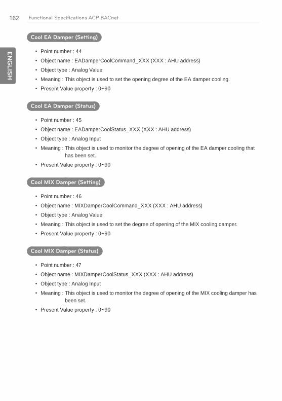
162
EN
GLIS
H
Functional Specifications ACP BACnet
Cool EA Damper (Setting)
Point number : 44
Object name : EADamperCoolCommand_XXX (XXX : AHU address)
Object type : Analog Value
Meaning : This object is used to set the opening degree of the EA damper cooling.
Cool EA Damper (Status)
Point number : 45
Object name : EADamperCoolStatus_XXX (XXX : AHU address)
Object type : Analog Input
Meaning : This object is used to monitor the degree of opening of the EA damper cooling that has been set.
Cool MIX Damper (Setting)
Point number : 46
Object name : MIXDamperCoolCommand_XXX (XXX : AHU address)
Object type : Analog Value
Meaning : This object is used to set the degree of opening of the MIX cooling damper.
Cool MIX Damper (Status)
Point number : 47
Object name : MIXDamperCoolStatus_XXX (XXX : AHU address)
Object type : Analog Input
Meaning : This object is used to monitor the degree of opening of the MIX cooling damper has been set.

163E
NG
LIS
HFunctional Specifications ACP BACnet
Heat OA Damper (Setting)
Point number : 48
Object name : OADamperHeatCommand_XXX (XXX : AHU address)
Object type : Analog Value
Meaning : This object is used to set the opening degree of OA damper Heating.
Heat OA Damper (Status)
Object name : OADamperHeatStatus_XXX (XXX : AHU address)
Object type : Analog Input
Meaning : This object is used to monitor the degree of opening of OA heating damper is set.
Heat EA Damper (Setting)
Point number : 50
Object name : EADamperHeatCommand_XXX (XXX : AHU address)
Object type : Analog Value
Meaning : This object is used to set the opening degree of the EA damper Heating.
Heat EA Damper (Status)
Point number : 51
Object name : EADamperHeatStatus_XXX (XXX : AHU address)
Object type : Analog Input
Meaning : This object is used to monitor the degree of opening of the EA heating damper is set.
Heat MIX Damper (Setting)
Point number : 52
Object name : MIXDamperHeatCommand_XXX (XXX : AHU address)
Object type : Analog Value
Meaning : This object is used to set the degree of opening of the MIX damper Heating.
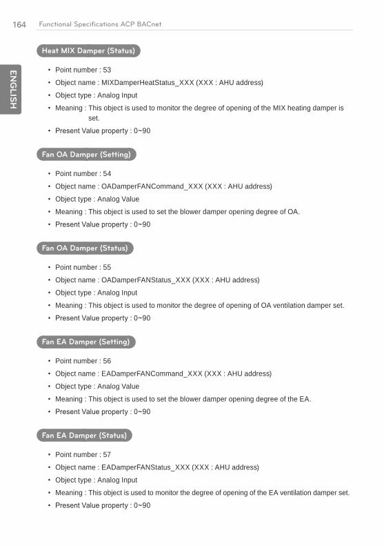
164
EN
GLIS
H
Functional Specifications ACP BACnet
Heat MIX Damper (Status)
Point number : 53
Object name : MIXDamperHeatStatus_XXX (XXX : AHU address)
Object type : Analog Input
Meaning : This object is used to monitor the degree of opening of the MIX heating damper is set.
Fan OA Damper (Setting)
Point number : 54
Object name : OADamperFANCommand_XXX (XXX : AHU address)
Object type : Analog Value
Meaning : This object is used to set the blower damper opening degree of OA.
Fan OA Damper (Status)
Point number : 55
Object name : OADamperFANStatus_XXX (XXX : AHU address)
Object type : Analog Input
Meaning : This object is used to monitor the degree of opening of OA ventilation damper set.
Fan EA Damper (Setting)
Point number : 56
Object name : EADamperFANCommand_XXX (XXX : AHU address)
Object type : Analog Value
Meaning : This object is used to set the blower damper opening degree of the EA.
Fan EA Damper (Status)
Point number : 57
Object name : EADamperFANStatus_XXX (XXX : AHU address)
Object type : Analog Input
Meaning : This object is used to monitor the degree of opening of the EA ventilation damper set.

165E
NG
LIS
HFunctional Specifications ACP BACnet
Fan MIX Damper (Setting)
Point number : 58
Object name : MIXDamperFANCommand_XXX (XXX : AHU address)
Object type : Analog Value
Meaning : This object is used to set the blower damper opening degree of the MIX.
Fan MIX Damper :Status
Object name : MIXDamperFANStatus_XXX (XXX : AHU address)
Object type : Analog Input
Meaning : This object is used to monitor the degree of opening of the MIX ventilation damper set.
Detailed attributes of each object, please refer to the table attributes on page 203

166
EN
GLIS
H
Functional Specifications ACP BACnet
Objects (Modbus-TCP)
Supported Function Code
Monitoring and controlling items of air conditioners supported are assigned with general function
codes specified by Modbus-TCP.
Function Name Code Description
Read Single Coil 01hRun/Stop(status), Lock(status), Swing(status), Alarm, Filter Sign(status), Mode Lock(status), Wind Flow Lock(status)
Read Holding Registers 03h
Operation Mode(status), Fan Speed(status), Room Temperature, Error Code, Set Room Temperature(status), Set Lower Temperature(status), Set Upper Temperature(status), User Mode(status)
Write Single Coil 05hRun/Stop(setting), Lock(setting), Swing(setting), Filter Sign Reset, Mode Lock(setting), Wind Flow Lock(setting)
Write Single Registers 06h
Operation Mode(setting), Fan Speed(setting), Set Room Temperature(setting), Set Lower Temperature(setting), Set Upper Temperature(setting), User Mode(setting)

167E
NG
LIS
HFunctional Specifications ACP BACnet
Regi
ster
Func
tion
Nam
eO
bjec
t Nam
e
(XXX
: Un
it ad
dres
s)In
activ
eAc
tive
1
Rea
dSi
ngle
Coi
l
ON
/OFF
Star
tSto
pSta
tus_
XX
XSt
opR
un
2SW
ING
Swin
gSta
tus_
XX
XPe
rmit
Proh
ibit
3LO
CK
Lock
Stat
us_X
XX
Perm
itPr
ohib
it
4M
OD
E LO
CK
Mod
eLoc
kSta
tus_
XX
XPe
rmit
Proh
ibit
5FA
N L
OC
KW
indF
low
Lock
Stat
us_X
XX
Perm
itPr
ohib
it
6TE
MP
LOC
KSe
tTem
pSta
tus-
XX
XPe
rmit
Proh
ibit
7AL
ARM
Alar
m_X
XX
Nor
mal
Abno
rmal
1
Writ
e Si
ngle
C
oil
ON
/OFF
Star
tSto
pCom
man
d_X
XX
Stop
Run
2SW
ING
Swin
gCom
man
d_X
XX
Perm
itPr
ohib
it
3LO
CK
Lock
Com
man
d_X
XX
Perm
itPr
ohib
it
4M
OD
E LO
CK
Mod
eLoc
kCom
man
d_X
XX
Perm
itPr
ohib
it
5FA
N L
OC
KW
indF
low
Lock
Com
man
d_X
XX
Perm
itPr
ohib
it
6TE
MP
LOC
KSe
tTem
pCom
man
d-X
XX
Perm
itPr
ohib
it

168
EN
GLIS
H
Functional Specifications ACP BACnet
Regi
ster
Func
tion
Nam
eO
bjec
t Nam
e
(XXX
: Un
it ad
dres
s)Te
xt-0
Text
-1Te
xt-2
Text
-3Te
xt-4
Text
-5
1
Rea
d H
oldi
ng
Reg
iste
rs
OPE
RAT
ION
M
OD
EM
odeS
tatu
s_X
XX
Coo
lD
ryFa
nAu
toH
eat
2FA
N S
PEED
FanS
peed
Stat
us_X
XX
Low
Mid
dle
Hig
hAu
to
3SE
T R
OO
M
TEM
PER
ATU
RE
SetT
empS
tatu
s_X
XX
°C
4U
P_SE
TTEM
PSe
tUpp
erTe
mp
Stat
us_X
XX
°C
5LO
_SET
TEM
PSe
tLow
erTe
mp
Stat
us_X
XX
°C
6R
OO
M
TEM
PER
ATU
RE
Roo
mTe
mp_
XX
X°C
7ER
RO
R C
OD
EM
alfu
nctio
nCod
e_X
XX
Ref
eren
ce L
G o
rigin
al E
rror
Cod
e
1
Writ
e Si
ngle
R
egis
ters
OPE
RAT
ION
M
OD
EM
odeC
omm
and_
XX
XC
ool
Dry
Fan
Auto
Hea
t
2FA
N S
PEED
FanS
peed
C
omm
and_
XX
XLo
wM
iddl
eH
igh
Auto
3SE
T R
OO
M
TEM
PER
ATU
RE
SetT
emp
Com
man
d_X
XX
°C
4U
P_SE
TTEM
PSe
tUpp
erTe
mp
Com
man
d_X
XX
°C
5LO
_SET
TEM
PSe
tLow
erTe
mp
Com
man
d_X
XX
°C

169E
NG
LIS
HFunctional Specifications ACP BACnet
Regi
ster
Func
tion
Nam
eO
bjec
t Nam
e
(XXX
: Ve
ntila
tion
addr
ess)
Inac
tive
Activ
e
1
Coi
l Rea
d
ON
/OFF
Star
tSto
pSta
tus_
XX
XSt
opR
un
2LO
CK
Lock
Stat
us_X
XX
Perm
itPr
ohib
it
3FI
LTER
SIG
NFi
lterS
ign_
XX
XO
ffO
n
4AL
ARM
Alar
m_X
XX
Stop
Run
5H
RV_
AC_O
PER
Hrv
Star
tSto
pSta
tus_
XX
XSt
opR
un
6H
RV_
HU
MID
IFY
Hrv
Hum
idify
Stat
us_X
XX
Off
On
1
Writ
e Si
ngle
C
oil
ON
/OFF
Star
tSto
pCom
man
d_X
XX
Stop
Run
2LO
CK
Lock
Com
man
d_X
XX
Perm
itPr
ohib
it
3FI
LTER
SIG
N R
ESET
Filte
rSig
nRes
et_X
XX
Res
et(O
ff)Vo
id(O
n)
5H
RV_
AC_O
PER
Hrv
Star
tSto
pCom
man
d_X
XX
Stop
Run
6H
RV_
HU
MID
IFY
Hrv
Hum
idify
Com
man
d_X
XX
Off
On

170
EN
GLIS
H
Functional Specifications ACP BACnet
Regi
ster
Func
tion
Nam
eO
bjec
t Nam
e
(XXX
: Ve
ntila
tion
addr
ess)
Text
-0Te
xt-1
Text
-2Te
xt-3
Text
-4Te
xt-5
1
Rea
d H
oldi
ng
Reg
iste
rs
OPE
RAT
ION
M
OD
EM
odeS
tatu
s_X
XX
Hea
t Ex
chan
geAu
toN
orm
al
2FA
N S
PEED
FanS
peed
Stat
us_X
XX
Low
Hig
hSu
per
Hig
hAu
to
3U
SER
MO
DE
Use
rMod
eSta
tus_
XX
XQ
uick
O
pera
tion
Ener
gy
Savi
ngH
eat
4ER
RO
R C
OD
EM
alfu
nctio
nCod
e_X
XX
Ref
eren
ce L
G o
rigin
al E
rror
Cod
e
5H
RV_
AC_M
OD
EH
rvM
odeS
tatu
s_X
XX
Coo
lAu
toH
eat
6H
RV_
SETT
EMP
Hrv
SetT
emps
tatu
s_X
XX
°C
1
Writ
e Si
ngle
R
egis
ters
OPE
RAT
ION
M
OD
EM
odeC
omm
and_
XX
XH
eat
Exch
ange
Auto
Nor
mal
2FA
N S
PEED
FanS
peed
C
omm
and_
XX
XLo
wH
igh
Supe
r H
igh
Auto
3U
SER
MO
DE
Use
rMod
eSta
tus_
XX
XQ
uick
O
pera
tion
Ener
gy
Savi
ngH
eat
5H
RV_
AC_M
OD
EH
rvM
odeS
tatu
s_X
XX
Coo
lAu
toH
eat
6H
RV_
SETT
EMP
Hrv
SetT
emps
tatu
s_X
XX
°C
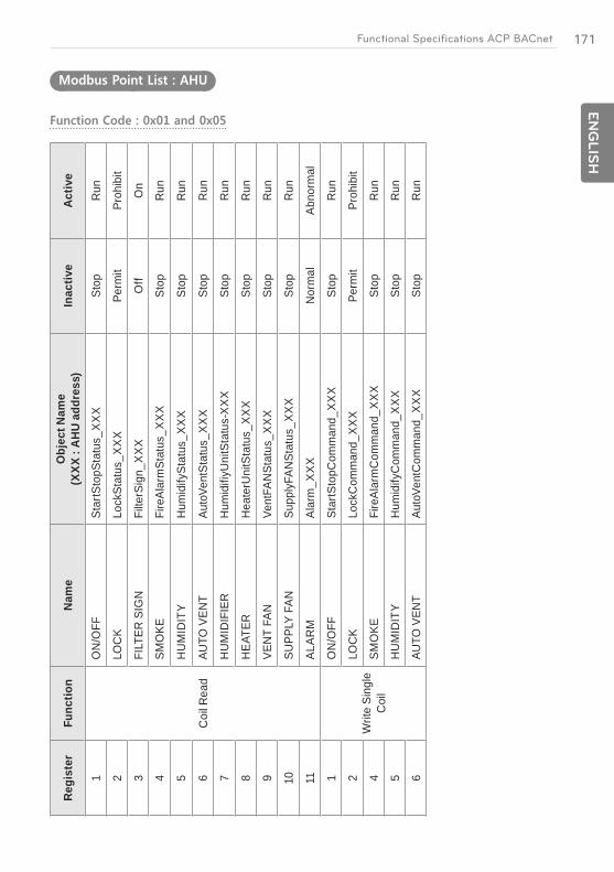
171E
NG
LIS
HFunctional Specifications ACP BACnet
Regi
ster
Func
tion
Nam
eO
bjec
t Nam
e
(XXX
: A
HU
addr
ess)
Inac
tive
Activ
e
1
Coi
l Rea
d
ON
/OFF
Star
tSto
pSta
tus_
XX
XSt
opR
un
2LO
CK
Lock
Stat
us_X
XX
Perm
itPr
ohib
it
3FI
LTER
SIG
NFi
lterS
ign_
XX
XO
ffO
n
4SM
OKE
Fire
Alar
mSt
atus
_XX
XSt
opR
un
5H
UM
IDIT
YH
umid
ifySt
atus
_XX
XSt
opR
un
6AU
TO V
ENT
Auto
Vent
Stat
us_X
XX
Stop
Run
7H
UM
IDIF
IER
Hum
idifi
yUni
tSta
tus-
XX
XSt
opR
un
8H
EAT
ERH
eate
rUni
tSta
tus_
XX
XSt
opR
un
VEN
T FA
NVe
ntFA
NSt
atus
_XX
XSt
opR
un
10SU
PPLY
FAN
Supp
lyFA
NSt
atus
_XX
XSt
opR
un
11AL
ARM
Alar
m_X
XX
Nor
mal
Abno
rmal
1
Writ
e Si
ngle
C
oil
ON
/OFF
Star
tSto
pCom
man
d_X
XX
Stop
Run
2LO
CK
Lock
Com
man
d_X
XX
Perm
itPr
ohib
it
4SM
OKE
Fire
Alar
mC
omm
and_
XX
XSt
opR
un
5H
UM
IDIT
YH
umid
ifyC
omm
and_
XX
XSt
opR
un
6AU
TO V
ENT
Auto
Vent
Com
man
d_X
XX
Stop
Run
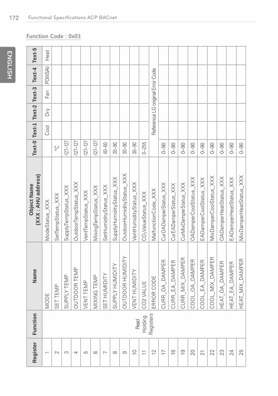
172
EN
GLIS
H
Functional Specifications ACP BACnet
Regi
ster
Func
tion
Nam
eO
bjec
t Nam
e
(XXX
: A
HU
addr
ess)
Text
-0Te
xt-1
Text
-2Te
xt-3
Text
-4Te
xt-5
1
Read
H
oldi
ng
Reg
iste
rs
MO
DE
Mod
eSta
tus_
XX
XC
ool
Dry
Fan
POW
SAV
Hea
t
2SE
T TE
MP
SetT
empS
tatu
s_X
XX
°C
3SU
PPLY
TEM
PSu
pply
Tem
pSta
tus_
XX
X-12
7~12
7
4O
UTD
OO
R T
EMP
Out
door
Tem
pSta
tus_
XX
X-12
7~12
7
5V
ENT
TEM
PVe
ntTe
mpS
tatu
s_X
XX
-127~
127
6M
IXIN
G T
EMP
Mix
ingT
empS
tatu
s_X
XX
-127~
127
7SE
T H
UM
IDIT
YSe
tHum
idity
Stat
us_X
XX
40~6
0
8SU
PPLY
HU
MID
ITY
Supp
lyH
umid
itySt
atus
_XX
X30
~90
9O
UTD
OO
R H
UM
IDIT
YO
utdo
orH
umid
itySt
atus
_XX
X30
~90
10V
ENT
HU
MID
ITY
Vent
Hum
idity
Stat
us_X
XX
30~9
0
11C
O2
VALU
EC
O2V
alue
Stat
us_X
XX
0~25
5
12ER
RO
R C
OD
EM
alfu
nctio
nCod
e_X
XX
Refe
renc
e LG
orig
inal
Erro
r Cod
e
17C
UR
R_O
A_D
AM
PER
Cur
OA
Dam
perS
tatu
s_X
XX
0~90
18C
UR
R_E
A_D
AM
PER
Cur
EAD
ampe
rSta
tus_
XX
X0~
90
19C
UR
R_M
IX_D
AM
PER
CurM
ixD
ampe
rSta
tus_
XX
X0~
90
20C
OO
L_O
A_D
AM
PER
OA
Dam
perC
oolS
tatu
s_X
XX
0~90
21C
OO
L_E
A_D
AM
PER
EA
Dam
perC
oolS
tatu
s_X
XX
0~90
22C
OO
L_M
IX_D
AM
PER
Mix
Dam
perC
oolS
tatu
s_X
XX
0~90
23H
EAT
_OA
_DA
MPE
RO
AD
ampe
rHea
tSta
tus_
XX
X0~
90
24H
EAT
_EA
_DA
MPE
RE
AD
ampe
rHea
tSta
tus_
XX
X0~
90
25H
EAT
_MIX
_DA
MPE
RM
ixD
ampe
rHea
tSta
tus_
XX
X0~
90
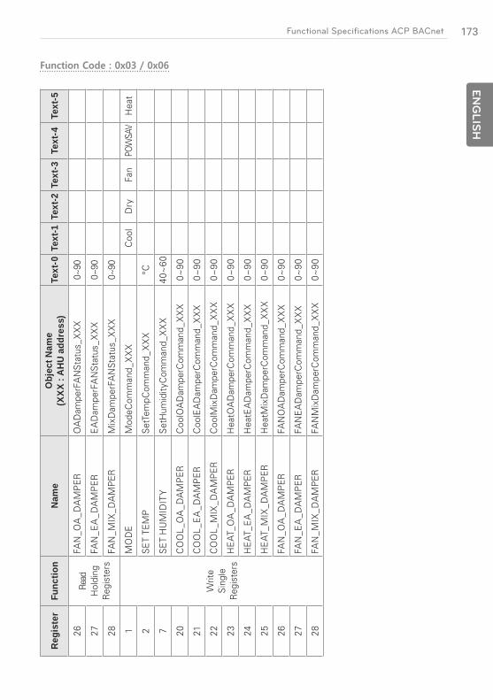
173E
NG
LIS
HFunctional Specifications ACP BACnet
Regi
ster
Func
tion
Nam
eO
bjec
t Nam
e
(XXX
: A
HU
addr
ess)
Text
-0Te
xt-1
Text
-2Te
xt-3
Text
-4Te
xt-5
26Re
ad
Hol
ding
R
egis
ters
FAN
_OA
_DA
MPE
RO
AD
ampe
rFA
NSt
atus
_XX
X0~
90
27FA
N_E
A_D
AM
PER
EA
Dam
perF
AN
Stat
us_X
XX
0~90
28FA
N_M
IX_D
AM
PER
Mix
Dam
perF
AN
Stat
us_X
XX
0~90
1
Writ
e Si
ngle
R
egis
ters
MO
DE
Mod
eCom
man
d_X
XX
Coo
lD
ryFa
nPO
WSA
VH
eat
2SE
T TE
MP
SetT
empC
omm
and_
XX
X°C
7SE
T H
UM
IDIT
YSe
tHum
idity
Com
man
d_X
XX
40~
60
20C
OO
L_O
A_D
AM
PER
Coo
lOA
Dam
perC
omm
and_
XX
X0~
90
21C
OO
L_E
A_D
AM
PER
Coo
lEA
Dam
perC
omm
and_
XX
X0~
90
22
CO
OL_
MIX
_DA
MPE
RC
oolM
ixD
ampe
rCom
man
d_X
XX
0~90
23H
EAT
_OA
_DA
MPE
RH
eatO
AD
ampe
rCom
man
d_X
XX
0~90
24H
EAT
_EA
_DA
MPE
RH
eatE
AD
ampe
rCom
man
d_X
XX
0~90
25H
EAT
_MIX
_DA
MPE
RH
eatM
ixD
ampe
rCom
man
d_X
XX
0~90
26FA
N_O
A_D
AM
PER
FAN
OA
Dam
perC
omm
and_
XX
X0~
90
27FA
N_E
A_D
AM
PER
FAN
EA
Dam
perC
omm
and_
XX
X0~
90
28FA
N_M
IX_D
AM
PER
FAN
Mix
Dam
perC
omm
and_
XX
X0~
90

174
EN
GLIS
H
Functional Specifications ACP BACnet
Example of Point Table
The point table below is passed to BMS, and BMS registers the object.
Case Indoor
Function Code Device No. Product No. Point Instance No. Name
1 0 0 0 0x00000 ON/OFF status
5 0 0 0 0x00000 ON/OFF Setting
1 0 1 0 0x00010 ON/OFF status
5 0 1 0 0x00010 ON/OFF Setting
1 1 0 0 0x00100 ON/OFF status
5 1 0 0 0x00100 ON/OFF Setting
3 0 0 0 0x40000 Mode status
6 0 0 0 0x40000 Mode Setting
3 0 1 0 0x40010 Mode status
6 0 1 0 0x40010 Mode Setting
3 1 0 0 0x40100 Mode status
6 1 0 0 0x40100 Mode Setting
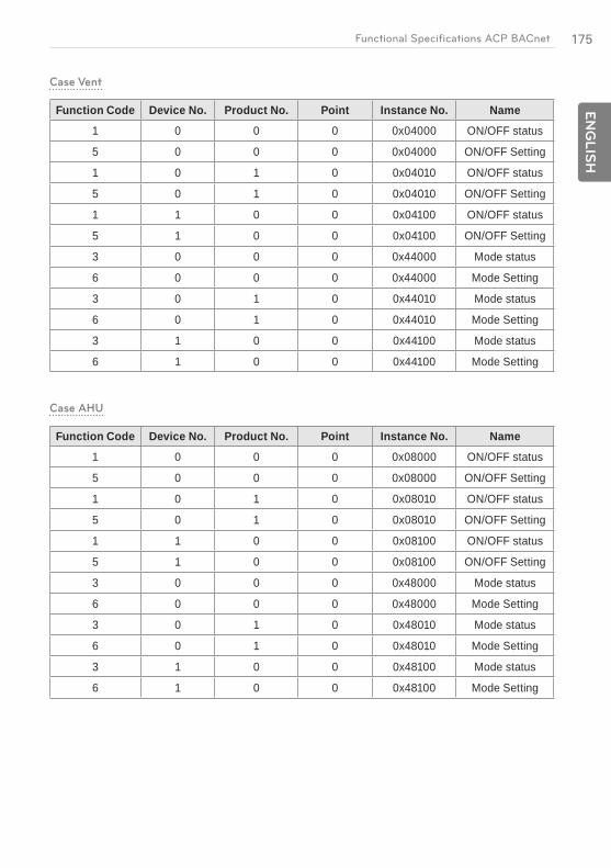
175E
NG
LIS
HFunctional Specifications ACP BACnet
Case Vent
Function Code Device No. Product No. Point Instance No. Name
1 0 0 0 0x04000 ON/OFF status
5 0 0 0 0x04000 ON/OFF Setting
1 0 1 0 0x04010 ON/OFF status
5 0 1 0 0x04010 ON/OFF Setting
1 1 0 0 0x04100 ON/OFF status
5 1 0 0 0x04100 ON/OFF Setting
3 0 0 0 0x44000 Mode status
6 0 0 0 0x44000 Mode Setting
3 0 1 0 0x44010 Mode status
6 0 1 0 0x44010 Mode Setting
3 1 0 0 0x44100 Mode status
6 1 0 0 0x44100 Mode Setting
Case AHU
Function Code Device No. Product No. Point Instance No. Name
1 0 0 0 0x08000 ON/OFF status
5 0 0 0 0x08000 ON/OFF Setting
1 0 1 0 0x08010 ON/OFF status
5 0 1 0 0x08010 ON/OFF Setting
1 1 0 0 0x08100 ON/OFF status
5 1 0 0 0x08100 ON/OFF Setting
3 0 0 0 0x48000 Mode status
6 0 0 0 0x48000 Mode Setting
3 0 1 0 0x48010 Mode status
6 0 1 0 0x48010 Mode Setting
3 1 0 0 0x48100 Mode status
6 1 0 0 0x48100 Mode Setting
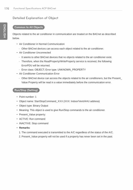
176
EN
GLIS
H
Functional Specifications ACP BACnet
Detailed Explanation of Object
Common to All Objects
Objects related to the air conditioner in communication are treated on the BACnet as described below.
Air Conditioner in Normal Communication
- Other BACnet devices can access each object related to the air conditioner.Air Conditioner Unconnected
- It seems to other BACnet devices that no objects related to the air conditioner exist. - Therefore, when the ReadProperty/WriteProperty service is received, the following
ErrorPDU will be returned. - Error class: OBJECT; Error type: UNKNOWN_PROPERTYAir Conditioner Communication Error
- Other BACnet device can access the objects related to the air conditioners, but the Present_Value Property will be read in a value immediately before the communication error.
Run/Stop (Setting)
Point number: 1
Object name: StartStopCommand_XXX (XXX: Indoor/Vent/AHU address)
Object type: Binary Output
Meaning: This object is used to give Run/Stop commands to the air conditioner.
Present_Value property:
ACTIVE: Run command
INACTIVE: Stop command
Remarks:
1. The command executed is transmitted to the A/C regardless of the status of the A/C.2. Present_Value property will not be used if a property has never been set in the past.

177E
NG
LIS
HFunctional Specifications ACP BACnet
Run/Stop (Status)
Point number: 2
Object name: StartStopStatus_XXX (XXX: Indoor/Vent/AHU address)
Object type: Binary Input
Meaning: This object is used to monitor the Run/Stop status of the air conditioner.
Present_Value property:
ACTIVE: Run
INACTIVE: Stop
Remarks: If there is an operation error, the Present_Value property will be set to ACTIVE regardless of whether the A/C is in operation or not.
Lock (Setting)
Point number: 3
Object name: LockCommand_XXX (XXX: Indoor/Vent/AHU address)
Object type: Binary Output
Meaning: This object is used to set the Lock of the A/C's control authority.
Present_Value property:
ACTIVE: Lock (Restricted)
INACTIVE: Unlock (Not restricted)
Lock (Status)
Point number: 4
Object name: LockStatus_XXX (XXX: Indoor/Vent/AHU address)
Object type: Binary Input
Meaning: This object is used to monitor the Lock of the A/C's control authority.
Present_Value property:
ACTIVE: Lock (Restricted)
INACTIVE: Unlock (Not restricted)

178
EN
GLIS
H
Functional Specifications ACP BACnet
Filter Sign
Point number: 5
Object name: FilterSign_XXX (XXX: Vent/AHU address)
Object type: Binary Input
Meaning: This object is used to monitor the status of the filters for vent.
Present_Value property:
ACTIVE: Filter sign information is turned ON.
INACTIVE: Filter sign information is OFF.
Remarks: This object supports the Intrinsic Reporting function. When the Present_Value property changes, the corresponding Event will be transmitted if the Event has been registered.
Filter Sign Reset
Point number: 6
Object name: FilterSignReset_XXX (XXX: Vent/AHU address)
Object type: Binary Value
Meaning: This object is used to reset the vent's limit indication.
Present_Value property:
INACTIVE: Filter indication information is reset.
Remarks:
1. During a read operation of the Present_Value property, the Fliter Limit Sign Reset will be always the same value as the Filter Limit Sign object.
2. Only if INACTIVE is written to the Present_Value property during a write operation, the filter sign information resets ON signs and nothing will be executed even if ACTIVE is written.
3. This object supports the Intrinsic Reporting function. When the Present_Value property changes, the corresponding Event will be transmitted if the Event has been registered.

179E
NG
LIS
HFunctional Specifications ACP BACnet
Operation Mode (Setting)
Point number: 7
Object name: ModeCommand_XXX (XXX: Indoor/Vent/AHU address)
Object type: Multistate Output
Meaning: This object is used to set the operation modes of the air conditioner.
Present_Value property:
Indoor Vent1 : Cool HEX
2 : Dry Auto
3 : Fan Normal
4 : Auto -
5 : Heat -
Remarks:
1. The Present_Value property will be set to "1: Cool" as the default value if property has never been set in the past.
2. The air conditioner will ignore the command to an object that does not have right to select operation mode. Therefore, the controlled/monitored system must not use this object for the air conditioner without the right to select operation mode.
Operation Mode (Status)
Point number: 8
Object name: ModeStatus_XXX (XXX: Indoor/Vent/AHU address)
Object type: Multistate Input
Meaning: This object is used to monitor the operation modes of the air conditioner.
Present_Value property:
Indoor Vent1 : Cool HEX
2 : Dry Auto
3 : Fan Normal
4 : Auto -
5 : Heat -

180
EN
GLIS
H
Functional Specifications ACP BACnet
Swing (Setting)
Object name: SwingCommand_XXX (XXX: Indoor address)
Object type: Binary Output
Meaning: This object is to set the air direction of the indoor unit.
Present_Value property:
ACTIVE: Run
INACTIVE: Stop
Swing (Status)
Point number: 10
Object name: SwingStatus_XXX (XXX: A/C unit address)
Object type: Binary Input
Meaning: This object is to monitor the air direction of the A/C.
Present_Value property:
ACTIVE: Swing_On
INACTIVE: Swing_Off
Fan Speed (Setting)
Point number: 11
Object name: FanSpeedCommand_XXX (XXX: A/C unit address)
Object type: Multistate Output
Meaning: This object is to set the airflow of the A/C.
Present_Value property:
Indoor Vent1 : Low Low
2 : Middle High
3 : High Super High
4 : Auto Auto
Remarks: The A/C will disregard the command which the object which can't select the operation mode. Therefore, controlled/monitored system shouldn't use the object which can't select the operation mode.

181E
NG
LIS
HFunctional Specifications ACP BACnet
Fan Speed (Status)
Point number: 12
Object name: FanSpeedStatus_XXX (XXX: Indoor/Vent addresss)
Object type: Multistate Input
Meaning: This object is to monitor the airflow of the A/C.
Present_Value property:
Indoor Vent1 : Low Low
2 : Middle High
3 : High Super High
4 : Auto Auto
Remarks: Present_value property will be set to "1:Low" as the default result if the property has not been set in the past.
Set Room Temperature
Point number: 13
Object name: SetRoomTemp_XXX (XXX: Indoor/AHU address)
Object type: Analog Value
Meaning: This object is used to set the room temperature for the air conditioner.
Present_Value property:
Temperature(°C)
Remarks:
1. This unit is for indoor units only, and the approximate set temperature range is 18 ~ 35°C.2. When COV registration is made, the COV will be reported the moment a temperature change
of at least 1°C is detected.
Room Temperature
Point number: 14
Object name: RoomTemp_XXX (XXX: Indoor/AHU address)
Object type: Analog Input
Meaning: This object is used to monitor room temperature which the indoor unit is placed.
Present_Value property:
Temperature(°C)
Remarks: This object is for indoor units only, and reports the room temperature data measured by the indoor units.

182
EN
GLIS
H
Functional Specifications ACP BACnet
Alarm
Point number: 15
Object name: Alarm_XXX (XXX: Indoor/Vent/AHU address)
Object type: Binary Input
Meaning: This object is used to monitor the Alarm.
Present_Value property:
ACTIVE: Alarm_On
INACTIVE: Alarm_Off
Error Code
Point number: 16
Object name: MalfunctionCode_XXX (XXX: Indoor/Vent/AHU address)
Object type: Analog Input
Meaning: This object is used to monitor the details of the error status when the air conditioner
has an error.
Present_Value property:
Error code(Range is 1 to 255)
Remarks: This object's error code descriptions should be referred to the corresponding table at the "Reference LG original Error Code".
User Mode (Setting)
Point number: 17
Object name: UserModeCommand_XXX (XXX: Vent address)
Object type: Multi-state Output
Meaning: This object is used to set the basic operation mode in vent and also additional
operation mode (quick fresh, energy efficiency, and heating).
Present_Value property:
1: Quick
2: Saving
3: Heater
Remarks: This object is for vent only, and will not apply if the property has not been set in the past.
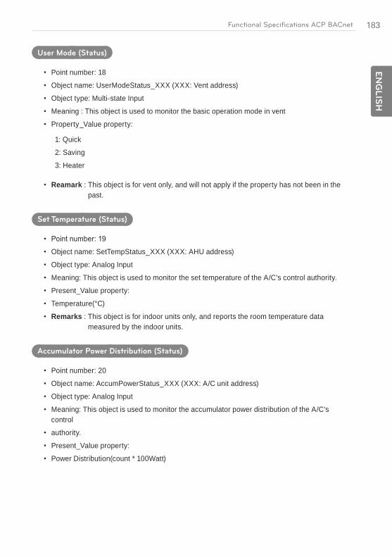
183E
NG
LIS
HFunctional Specifications ACP BACnet
User Mode (Status)
Point number: 18
Object name: UserModeStatus_XXX (XXX: Vent address)
Object type: Multi-state Input
Meaning : This object is used to monitor the basic operation mode in vent
Property_Value property:
1: Quick
2: Saving
3: Heater
Reamark : This object is for vent only, and will not apply if the property has not been in the past.
Set Temperature (Status)
Object name: SetTempStatus_XXX (XXX: AHU address)
Object type: Analog Input
Meaning: This object is used to monitor the set temperature of the A/C's control authority.
Present_Value property:
Temperature(°C)
Remarks : This object is for indoor units only, and reports the room temperature data measured by the indoor units.
Accumulator Power Distribution (Status)
Point number: 20
Object name: AccumPowerStatus_XXX (XXX: A/C unit address)
Object type: Analog Input
Meaning: This object is used to monitor the accumulator power distribution of the A/C's control
authority.
Present_Value property:
Power Distribution(count * 100Watt)
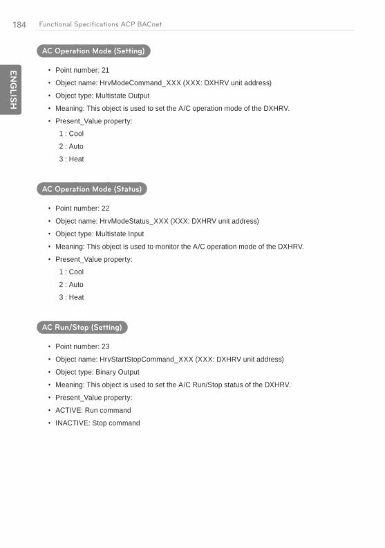
184
EN
GLIS
H
Functional Specifications ACP BACnet
AC Operation Mode (Setting)
Point number: 21
Object name: HrvModeCommand_XXX (XXX: DXHRV unit address)
Object type: Multistate Output
Meaning: This object is used to set the A/C operation mode of the DXHRV.
Present_Value property:
1 : Cool
2 : Auto
3 : Heat
AC Operation Mode (Status)
Point number: 22
Object name: HrvModeStatus_XXX (XXX: DXHRV unit address)
Object type: Multistate Input
Meaning: This object is used to monitor the A/C operation mode of the DXHRV.
Present_Value property:
1 : Cool
2 : Auto
3 : Heat
AC Run/Stop (Setting)
Point number: 23
Object name: HrvStartStopCommand_XXX (XXX: DXHRV unit address)
Object type: Binary Output
Meaning: This object is used to set the A/C Run/Stop status of the DXHRV.
Present_Value property:
ACTIVE: Run command
INACTIVE: Stop command

185E
NG
LIS
HFunctional Specifications ACP BACnet
AC Run/Stop (Setting)
Point number: 24
Object name: HrvStartStopStatus_XXX (XXX: DXHRV unit address)
Object type: Binary Input
Meaning: This object is used to monitor the A/C Run/Stop status of the DXHRV.
Present_Value property:
ACTIVE: Run
INACTIVE: Stop
AC Humidify (Setting)
Point number: 25
Object name: HrvHumidifyCommand_XXX (XXX: DXHRV unit address)
Object type: Binary Output
Meaning: This object is used to set the A/C humidify status of the DXHRV.
Present_Value property:
ACTIVE: ON command
INACTIVE: OFF command
AC Humidify (Status)
Point number: 26
Object name: HrvStartStopStatus_XXX (XXX: DXHRV unit address)
Object type: Binary Input
Meaning: This object is used to monitor the A/C humidify status of the DXHRV.
Present_Value property:
ACTIVE: ON
INACTIVE: OFF

186
EN
GLIS
H
Functional Specifications ACP BACnet
Set Upper Temperature (Setting)
Point number: 27
Object name: SetUpperTempCommand_XXX (XXX: A/C unit address)
Object type: Analog Value
Meaning: This object is used to set the upper temperature for the air conditioner.
Present_Value property:
Temperature(°C)
Remarks: .
1. This unit is for indoor units only, and the approximate set upper temperature range is 18 ~ 30°C.
2. 1°C is detected.
Set Upper Temperature (Status)
Point number: 28
Object name: SetUpperTempStatus_XXX (XXX: A/C unit address)
Object type: Analog Input
Meaning: This object is used to monitor set upper temperature which the indoor unit is placed.
Present_Value property:
Temperature(°C)
Remarks: This object is for indoor units only, and reports the set upper temperature data measured by the indoor units.
Set Lower Temperature (Setting)
Object name: SetLowerTempCommand_XXX (XXX: A/C unit address)
Object type: Analog Value
Meaning: This object is used to set the lower temperature for the air conditioner.
Present_Value property:
Temperature(°C)
Remarks:
1. This unit is for indoor units only, and the approximate set lower temperature range is 18 ~ 30°C.
2. 1°C is detected.
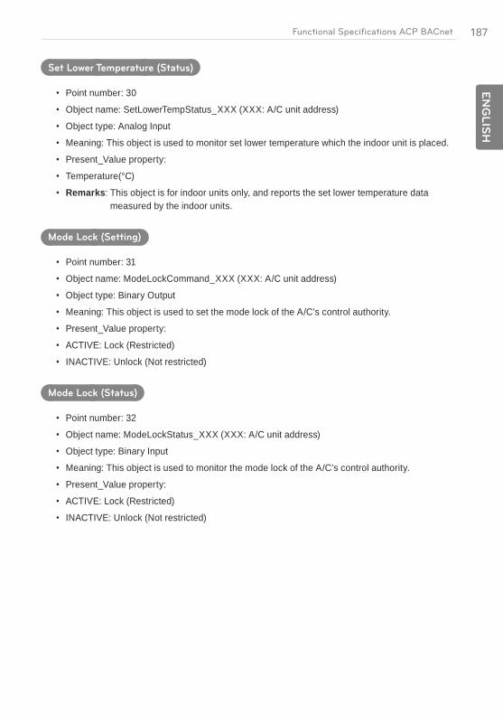
187E
NG
LIS
HFunctional Specifications ACP BACnet
Set Lower Temperature (Status)
Point number: 30
Object name: SetLowerTempStatus_XXX (XXX: A/C unit address)
Object type: Analog Input
Meaning: This object is used to monitor set lower temperature which the indoor unit is placed.
Present_Value property:
Temperature(°C)
Remarks: This object is for indoor units only, and reports the set lower temperature data measured by the indoor units.
Mode Lock (Setting)
Point number: 31
Object name: ModeLockCommand_XXX (XXX: A/C unit address)
Object type: Binary Output
Meaning: This object is used to set the mode lock of the A/C's control authority.
Present_Value property:
ACTIVE: Lock (Restricted)
INACTIVE: Unlock (Not restricted)
Mode Lock (Status)
Point number: 32
Object name: ModeLockStatus_XXX (XXX: A/C unit address)
Object type: Binary Input
Meaning: This object is used to monitor the mode lock of the A/C's control authority.
Present_Value property:
ACTIVE: Lock (Restricted)
INACTIVE: Unlock (Not restricted)

188
EN
GLIS
H
Functional Specifications ACP BACnet
Initialization at the Start Up
The system is designed to automatically recognize the connected air conditioners. Therefore, a period of approximately one minute will be required to recognize all the air conditioners after the system is turn on. During this period, the following error PDU may be returned when an object corresponding to an air conditioner is accessed.
ErrorClass = Object; ErrorCode = Unknown_Object
If an attempt is made to read the Object List property of the Device object from an air conditioner during the above period of recognition, the following error PDU will be returned, unless the air conditioner has been recognize:
ErrorClass = Device; ErrorCode = Configuration_In_Progress
Communication error response of ACP BACnet, please refer to ACP-BACnet Error Response Table on page 205.
Clock Setting
The Timesynchronization service allows clock settings by the local time.
Furthermore, the UTCTimesycchronization allows clock settings by UTC

189E
NG
LIS
HFunctional Specifications ACP BACnet
Report Function
Event Notification
1) Registration of Event Notification DestinationIt is possible to use the AddListElement service to register notification destination information on the Recipient List property of the Notification Class object.
2) Deletion of Event Notification DestinationThe RemoveListElement service can be used to delete notification destination information from the Notification Class object.
3) Event Notification Destination in MemoryThe registered event notification destination is stored in the memory. When the system is turned on, the event notification destination will be initialized with the stored information. The Event notification destination will be stored five seconds after the registration or deletion.
COV(Change of Value) Notification
A request for COV registration is accepted through the SubscribeCOV service.
1) Setting of Confirmed or Unconfirmed COVThis item is supported according to the BACnet Specifications.
2) Setting of the desired lifetime of the subscriptionThis item is supported according to the BACnet Specifications.
When COV notification is made at the time of status change, the difference between the registered time and present time will be calculated. If the difference is greater than the registered lifetime of the subscription, the subscription will be judged expired and deleted. Therefore, if a clock time change is made, the lifetime of the subscription may differ from the value that has been set.
3) Memory after Interruption of Power Supply to SystemThis item is not supported. Registration information is not stored in the memory, and will be lost when the power is turned off. According to the BACnet Specifications, It is not required to guarantee preservation of subscriptions across power failure.
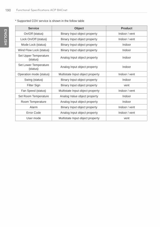
190
EN
GLIS
H
Functional Specifications ACP BACnet
* Supported COV service is shown in the follow table
Service Object Product
On/Off (status) Binary Input object property Indoor / vent
Lock On/Off (status) Binary Input object property Indoor / vent
Mode Lock (status) Binary Input object property Indoor
Wind Flow Lock (status) Binary Input object property Indoor
Set Upper Temperature (status) Analog Input object property Indoor
Set Lower Temperature (status) Analog Input object property Indoor
Operation mode (status) Multistate Input object property Indoor / vent
Swing (status) Binary Input object property Indoor
Filter Sign Binary Input object property vent
Fan Speed (status) Multistate Input object property Indoor / vent
Set Room Temperature Analog Value object property Indoor
Room Temperature Analog Input object property Indoor
Alarm Binary Input object property Indoor / vent
Error Code Analog Input object property Indoor / vent
User mode Multistate Input object property vent
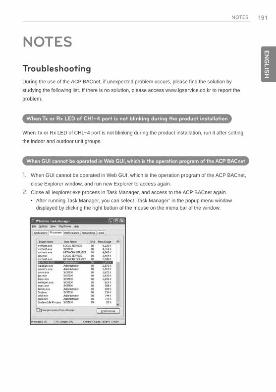
191E
NG
LIS
HNOTES
NOTES
Troubleshooting
During the use of the ACP BACnet, if unexpected problem occurs, please find the solution by studying the following list. If there is no solution, please access www.lgservice.co.kr to report the problem.
When Tx or Rx LED of CH1~4 port is not blinking during the product installation
When Tx or Rx LED of CH1~4 port is not blinking during the product installation, run it after setting the indoor and outdoor unit groups.
When GUI cannot be operated in Web GUI, which is the operation program of the ACP BACnet
1. When GUI cannot be operated in Web GUI, which is the operation program of the ACP BACnet, close Explorer window, and run new Explorer to access again.
2. Close all iexplorer.exe process in Task Manager, and access to the ACP BACnet again.After running Task Manager, you can select ‘Task Manager’ in the popup menu window displayed by clicking the right button of the mouse on the menu bar of the window.
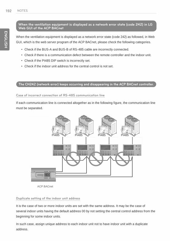
192
EN
GLIS
H
NOTES
When the ventilation equipment is displayed as a network error state (code 242) in LG Web GUI of the ACP BACnet
When the ventilation equipment is displayed as a network error state (code 242) as followed, in Web GUI, which is the web server program of the ACP BACnet, please check the following categories.
Check if the BUS-A and BUS-B of RS-485 cable are incorrectly connected.
Check if there is a communication defect between the remote controller and the indoor unit.
Check if the PI485 DIP switch is incorrectly set.
Check if the indoor unit address for the central control is not set.
The CH242 (network error) keeps occurring and disappearing in the ACP BACnet controller.
Case of incorrect connection of RS-485 communication line
If each communication line is connected altogether as in the following figure, the communication line must be separated.
PQNFB17C0
BACnet
PI485 PI485 PI485 PI485
ACP BACnet
Duplicate setting of the indoor unit address
It is the case of two or more indoor units are set with the same address. It may be the case of several indoor units having the default address 00 by not setting the central control address from the beginning for some indoor units.
In such case, assign unique address to each indoor unit not to have indoor unit with a duplicate address.
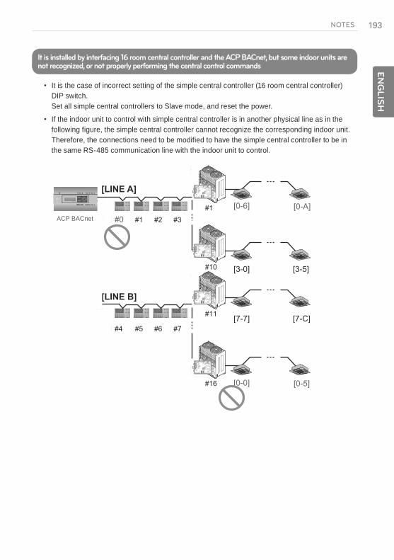
193E
NG
LIS
HNOTES
It is installed by interfacing 16 room central controller and the ACP BACnet, but some indoor units are not recognized, or not properly performing the central control commands
It is the case of incorrect setting of the simple central controller (16 room central controller) DIP switch. Set all simple central controllers to Slave mode, and reset the power.
If the indoor unit to control with simple central controller is in another physical line as in the following figure, the simple central controller cannot recognize the corresponding indoor unit. Therefore, the connections need to be modified to have the simple central controller to be in the same RS-485 communication line with the indoor unit to control.
[0-6]
[3-0]
[LINE A]
[LINE B]
[3-5]
[7-7] [7-C]
[0-A]
[0-5]
#1 #2 #3#0
#5 #6 #7#4
[0-0]
#1
#10
#11
#16
ACP BACnet
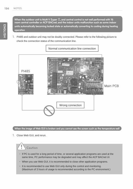
194
EN
GLIS
H
NOTES
When the outdoor unit is Multi V Super , and central control is not well performed with 16 room central controller or ACP BACnet, and the indoor units malfunction such as some indoor
units automatically becoming locked state or automatically converting to cooling during heating
operation
1. PI485 and outdoor unit may not be doubly connected. Please refer to the following picture to check the connection status of the communication line.
Normal communication line connection
Wrong connection
When the image of Web GUI is broken and you cannot see the screen such as the temperature well
1. Close Web GUI, and rerun.
Caution
If PC is used for a long period of time, or several application programs are used at the same time, PC performance may be degraded and may affect the ACP BACnet UI.
When you use Web GUI, it is recommended to close other application programs.
It is recommended to use Web GUI only during the control and monitoring. (Maximum of 3 hours of usage is recommended according to the PC environment.)
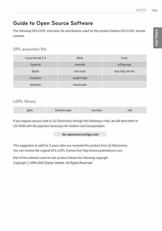
195E
NG
LIS
HNOTES
Guide to Open Source Software
The following GPL/LGPL execution file and libraries used for this product follows GPL/LGPL license contract.
GPL execution file
Linux kernel 2.4 fdisk lrzsz
Sysvinit Inetutils e2fsprogs
Bash net-tools boa http server
busybox stupid-ftpd
tinylogin traceroute
LGPL library
glibc linuxthreads ncurses zlib
If you request source code to LG Electronics through the following e-mail, we will send them in CD-ROM with the payment necessary for medium and transportation.
This suggestion is valid for 3 years after you received this product from LG Electronics. You can receive the original GPL/LGPL license from http://www.systemaircon.com.
Part of the software used for this product follows the following copyright. Copyright

196
EN
GLIS
H
NOTES
BIBBs
ACP BACnet Interoperability Building Blocks Supported(BIBBs)
Data Sharing BIBBS
( )
BIBB Type Supported ACP BACnet Service Initiate Execute
DS-RP-A Data Sharing-ReadProperty-A ReadProperty ×
DS-RP-B Data Sharing-ReadProperty-B ReadProperty ×
DS-RPM-A
Data Sharing-ReadPropertyMultiple-A ReadPropertyMultiple ×
DS-RPM-B
Data Sharing-ReadPropertyMultiple-B ReadPropertyMultiple ×
DS-RPC-A
Data Sharing-ReadPropertyConditiona-A ReadPropertyConditional ×
DS-RPC-B
Data Sharing-ReadPropertyConditiona-B ReadPropertyConditional ×
DS-WP-A Data Sharing-WriteProperty-A WriteProperty ×
DS-WP-B Data Sharing-WriteProperty-B WriteProperty ×
DS-WPM-A
Sharing-WritePropertyMultiple-A WritePropertyMultiple ×
DS-WPM-B
Data Sharing-WritePropertyMultiple-B WritePropertyMultiple ×
DS-COV-A Data Sharing-COV-A
SubscribeCOV ×
Confirmed COVNotification ×
Unconfirmed COVNotification ×
DS-COV-B Data Sharing-COV-B
SubscribeCOV ×
Confirmed COVNotification ×
Unconfirmed COVNotification ×
DS-COVP-A Data Sharing-COVP-A
SubscribeCOV ×
Confirmed COVNotification ×
Unconfirmed COVNotification ×
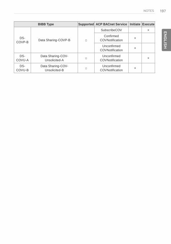
197E
NG
LIS
HNOTES
BIBB Type Supported ACP BACnet Service Initiate Execute
DS-COVP-B Data Sharing-COVP-B
SubscribeCOV ×
Confirmed COVNotification ×
Unconfirmed COVNotification ×
DS-COVU-A
Data Sharing-COV-Unsolicited-A
Unconfirmed COVNotification ×
DS-COVU-B
Data Sharing-COV-Unsolicited-B
Unconfirmed COVNotification ×

198
EN
GLIS
H
NOTES
Alarm and Event Management BIBBS
BIBB Type Supported ACP BACnet Service Initiate Execute
AE-N-A Alarm and Event-Notification-A
Confirmed EventNotification ×
Unconfirmed EventNotification ×
AE-N-I-B Alarm and Event-Notification Internal-B
Confirmed EventNotification ×
Unconfirmed EventNotification ×
AE-N-E-B
Alarm and Event-Notification External-B
Confirmed EventNotification ×
Unconfirmed EventNotification ×
AE-ACK-A Alarm and Event-ACK-A AcknowledgeAlarm ×
AE-ACK-B Alarm and Event-ACK-B AcknowledgeAlarm ×
AE-ASUM-A Alarm and Event-Summary-A GetAlarmSummary ×
AE-ASUM-B Alarm and Event-Summary-B GetAlarmSummary ×
AE-ESUM-A Event-Summary-A GetEnrollment
Summary ×
AE-ESUM-B Event-Summary-B GetEnrollment
Summary ×
AE-INFO-A Alarm and Event-Information-A GetEventInformation ×
AE-INFO-B Alarm and Event-Information-B GetEventInformation ×
AE-LS-A Alarm and Event-LifeSafety-A LifeSafetyOperation ×
AE-LS-B Alarm and Event-LifeSafety-B LifeSafetyOperation ×

199E
NG
LIS
HNOTES
Scheduling BIBBS
BIBB Type Supported ACP BACnet Service Initiate Execute
SCHED-AScheduling-A
(must support DS-RP-A and DS-WP-A)
SCHED-I-B
Scheduling-Internal-B(shall support DS-RP-B and
DS-WP-B)(shall also support ether DM-
TS-B or DS-UTC-B)
SCHED-E-B
Scheduling-External-B (shall support SCHED-I-B and
DS-WP-A)
Trending BIBBS
BIBB Type Supported ACP BACnet Service Initiate Execute
T-VMT-A Trending - Viewing and Modifying Trends-A ReadRange ×
T-VMT-I-B
Trending-Viewing and Modifying Trends Internal-B ReadRange ×
T-VMT-E-B
Trending-Viewing and Modifying Trends External-B ReadRange ×
T-ATR-A Trending - Automated Trend Retrieval-A
ConfirmedEvent Notification ×
edEventNoti ×
T-ATR-B Trending - Automated Trend Retrieval-B
ConfirmedEvent Notification ×
edEventNoti ×
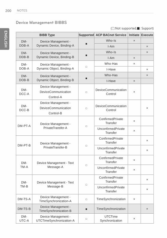
200
EN
GLIS
H
NOTES
Device Management BIBBS
BIBB Type Supported ACP BACnet Service Initiate Execute
DM-DDB-A
Device Management - Dynamic Device, Binding-A
Who-Is ×
I-Am ×
DM-DDB-B
Device Management - Dynamic Device, Binding-B
Who-Is ×
I-Am ×
DM-DOB-A
Device Management - Dynamic Object, Binding-A
Who-Has ×
I-Have ×
DM-DOB-B
Device Management - Dynamic Object, Binding-B
Who-Has ×
I-Have ×
DM-DCC-A
Device Management - DeviceCommunication
Control-A
DeviceCommunication Control ×
DM-DCC-B
Device Management - DeviceCommunication
Control-B
DeviceCommunication Control ×
DM-PT-A Device Management - PrivateTransfer-A
ConfirmedPrivate Transfer ×
UnconfirmedPrivate Transfer ×
DM-PT-B Device Management - PrivateTransfer-B
ConfirmedPrivate Transfer ×
UnconfirmedPrivate Transfer ×
DM-TM-A
Device Management - Text Message-A
ConfirmedPrivate Transfer ×
UnconfirmedPrivate Transfer ×
DM-TM-B
Device Management - Text Message-B
ConfirmedPrivate Transfer ×
UnconfirmedPrivate Transfer ×
DM-TS-A Device Management - TimeSynchronization-A TimeSynchronization ×
DM-TS-B Device Management - TimeSynchronization-B TimeSynchronization ×
DM-UTC-A
Device Management - UTCTimeSynchronization-A
UTCTime Synchronization ×
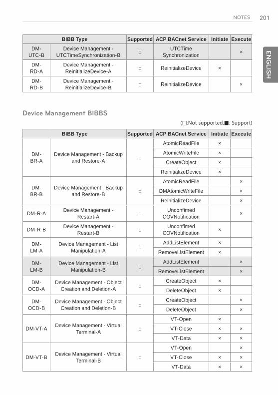
201E
NG
LIS
HNOTES
BIBB Type Supported ACP BACnet Service Initiate Execute
DM-UTC-B
Device Management - UTCTimeSynchronization-B
UTCTime Synchronization ×
DM-RD-A
Device Management - ReinitializeDevice-A ReinitializeDevice ×
DM-RD-B
Device Management - ReinitializeDevice-B ReinitializeDevice ×
Device Management BIBBS
BIBB Type Supported ACP BACnet Service Initiate Execute
DM-BR-A
Device Management - Backup and Restore-A
AtomicReadFile ×
AtomicWriteFile ×
CreateObject ×
ReinitializeDevice ×
DM-BR-B
Device Management - Backup and Restore-B
AtomicReadFile ×
DMAtomicWriteFile ×
ReinitializeDevice ×
DM-R-A Device Management - Restart-A
Unconfimed COVNotification ×
DM-R-B Device Management - Restart-B
Unconfimed COVNotification ×
DM-LM-A
Device Management - List Manipulation-A
AddListElement ×
RemoveListElement ×
DM-LM-B
Device Management - List Manipulation-B
AddListElement ×
RemoveListElement ×
DM-OCD-A
Device Management - Object Creation and Deletion-A
CreateObject ×
DeleteObject ×
DM-OCD-B
Device Management - Object Creation and Deletion-B
CreateObject ×
DeleteObject ×
DM-VT-A Device Management - Virtual Terminal-A
VT-Open ×
VT-Close × ×
VT-Data × ×
DM-VT-B Device Management - Virtual Terminal-B
VT-Open ×
VT-Close × ×
VT-Data × ×

202
EN
GLIS
H
NOTES
Network Management BIBBS
BIBB Type Supported ACP BACnet Service Initiate Execute
NM-CE-A
Network Management - Connection Establishment-A
Establish-Connection-To-Network ×
Disconnect-Connection-To-Network ×
NM-CE-B
Network Management - Connection Establishment-B
Establish-Connection-To-Network ×
Disconnect-Connection-To-Network ×
DM-BR-A
Network Management - Router Configuration-A
Who-Is-Router-To-Network ×
I-Am-Router-To-Network ×
I-Could-Be-Router-To-Network ×
Initialize-Routing-Table ×
Initialize-Routing-Table-Ack ×
NM-RC-B
Network Management - Router Configuration-B
Who-Is-Router-To-Network × ×
I-Am-Router-To-Network × ×
Initialize-Routing-Table ×
Initialize-Routing-Table-Ack ×

203E
NG
LIS
HNOTES
Multi - state Input Object Type
Property Identifier Property Datatype ACP BACnet BNU-BAC
Object_Identifier BACnetObjectIdentifier R R
Object_Name CharacterString R R
Object_Type BACnetObjectType R R
Present_Value Unsigned R1 R
Description CharacterString O R
Device_Type CharacterString O -
Status_Flags BACnetStatusFlags R R
Event_State BACnetEventState R R
Reliability BACnetReliability O2 -
Out_Of_Service Boolean R R
Number_Of_States Unsigned R R
State_Text CharacterString O -
Time_Delay Unsigned O3 -
Notification_Class Unsigned O3 -
Alarm_Values List of Unsigned O3 -
Fault_Values List of Unsigned O3 -
Event_Enable BACnetEventTransitionBits O3 -
Acked_Transitions BACnetEventTransitionBits O3 -
Notify_Type BACnetNotifyType O3 -
Event_Time_Stamps BACnetTimeStamp O3 -
Multi - state Output Object Type
Property Identifier Property Datatype ACP BACnet BNU-BAC
Object_Identifier BACnetObjectIdentifier R R
Object_Name CharacterString R R
Object_Type BACnetObjectType R R
Present_Value Unsigned W W
Description CharacterString O R
Device_Type CharacterString O -
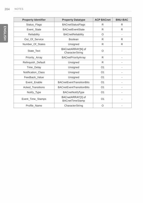
204
EN
GLIS
H
NOTES
Property Identifier Property Datatype ACP BACnet BNU-BAC
Status_Flags BACnetStatusFlags R R
Event_State BACnetEventState R R
Reliability BACnetReliability O -
Out_Of_Service Boolean R R
Number_Of_States Unsigned R R
State_Text CharacterString O -
Priority_Array BACnetPriorityArray R -
Relinquish_Default Unsigned R -
Time_Delay Unsigned O1 -
Notification_Class Unsigned O1 -
Feedback_Value Unsigned O1 -
Event_Enable BACnetEventTransitionBits O1 -
Acked_Transitions BACnetEventTransitionBits O1 -
Notify_Type BACnetNotifyType O1 -
Event_Time_Stamps BACnetTimeStamp O1 -
Profile_Name CharacterString O -

205E
NG
LIS
HNOTES
ACP-BACnet Error Response Table
Error PDU
Error PDU Error Class Error Code
Reading of the object list during the initialization of the LG-NET Device(0) Configuration_In_Progress(2)
Request to access to an object not installed. Object(1) Unknown_Object(31)
Request to access to a property not installed. Property(2) Unknown_Property(32)
Request to write to a prohibited area. Property(2) Write_Access_Denied(40)
Request to write in a format different from the property. Property(2)
Request to access to a specified index outside the array index range. Property(2) Invalid_Array_Index(42)
Request to write a value outside the permissible range. Property(2) Value_Out_Of_Range(37)
A COV registration request of more than 10 registration items. Resource(3) Other(0)
An Event registration request of more than 10 registration items. Resource(3) No_Space_To_Add_List_
Request for the deletion of an element not existing in the list. Service(5) Other(0)
Request for the execution of the AddListElement/RemoveListElement for a property that is not of List type.
Service(5) Property_Is_Not_List(22)
Reject PDU
Reject PDU Reject Reason
A propertyID or value overflow or underflow occurred during WritePropertyMultiple operation. Inconsistent_Parameter(2)
The type of parameter for the execution of the service is different in type. Invalid_Parameter_Data_Type(3)
An error was detected during tag decoding. Invalid_Tag(4)
A parameter shortage occurred during the execution of the service. Missing_Required_Parameter(5)
Too many arguments for the execution of the service. Too_Many_Arguments(7)
An attempt to execute an unsupported service with confirmation.

206
EN
GLIS
H
NOTES
Abort PDU
Reject PDU Reject Reason
Unable to process due to too many requests beyond the capacity. Buffer_Overflow(1)
The processing of segments was aborted because an expected APDU was received. Invalid_APDU_In_This_State(2)
The response side does not support the segment. Segmentation_Not_Supported(4)
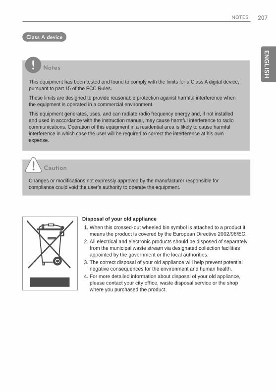
207E
NG
LIS
HNOTES
Class A device
Notes
This equipment has been tested and found to comply with the limits for a Class A digital device, pursuant to part 15 of the FCC Rules.
These limits are designed to provide reasonable protection against harmful interference when the equipment is operated in a commercial environment.
This equipment generates, uses, and can radiate radio frequency energy and, if not installed and used in accordance with the instruction manual, may cause harmful interference to radio communications. Operation of this equipment in a residential area is likely to cause harmful interference in which case the user will be required to correct the interference at his own expense.
Caution
Changes or modifications not expressly approved by the manufacturer responsible for compliance could void the user’s authority to operate the equipment.
Disposal of your old appliance1. When this crossed-out wheeled bin symbol is attached to a product it
2. All electrical and electronic products should be disposed of separately from the municipal waste stream via designated collection facilities appointed by the government or the local authorities.
3. The correct disposal of your old appliance will help prevent potential negative consequences for the environment and human health.
4. For more detailed information about disposal of your old appliance, please contact your city office, waste disposal service or the shop where you purchased the product.