

Kalle-Heikki Koskinen
Lifecycle Information Management
in a Product Information Model
Master’s Thesis submitted in partial fulfilment of the requirements
for the degree of Master of Science in Technology.
Espoo, September 23, 2017
Supervisor: Professor Jan Holmström

ii
Aalto University, P.O. BOX 11000, 00076 AALTO
www.aalto.fi
Abstract of the master’s thesis
Author Kalle-Heikki Koskinen
Title of thesis Lifecycle Information Management
in a Product Information Model
Master’s programme Degree Program in Energy Engineering and HVAC
Minor TU3001 Industrial Management
Thesis supervisor Professor Jan Holmström
Date September 23, 2017
Number of pages 64 + 9
Language English
In modern, global manufacturing business, value is increasingly created by
services related to products rather than the products themselves. In industries
related to the built environment, various products installed in the buildings are a
major asset for the operators and managers of buildings. Product Lifecycle
Management (PLM), managing and exploiting product-related information
throughout the lifecycle of the product, has become both a requirement and an
important tool for effective service business development.
Extensive and interactive PLM requires a universal system for information
exchange across the lifecycles of buildings and products. The objective of the
study is to define and implement the minimum requirements set by a product-
centric information exchange system in an IFC-based product information
model, based on use case of managing installed medical equipment in hospital
environment.
The study comprises a literature analysis and a use case. Late literature was
reviewed to analyse developments of intelligence and lifecycle management in
products and buildings. It was found that major challenges exist in exchanging
lifecycle information between stakeholders and across lifecycle stages. Based on
the analysis, it is proposed that using the technologies of building information
modelling and a product-centric information exchange system could provide
novel solutions to the identified challenges. In the use case, a method was
developed for incorporating an open, product-centric PLM information exchange
system into the existing IFC standard.
It was found that an URI-based, product-centric information exchange system
using external databases and product servers satisfies the requirements of
effective PLM information exchange. Additionally, it was found that using IFC
for product information modelling can effectively support such a system by
linking virtual building and product information models into the lifecycle
information stored in external servers.
Keywords: PLM, CL2M, IFC, BIM, BLM, PIM, Revit, lifecycle

iii
Aalto-yliopisto, PL 11000, 00076 AALTO
www.aalto.fi
Diplomityön tiivistelmä
Tekijä Kalle-Heikki Koskinen
Työn nimi Elinkaaritiedon hallinta tuotetietomallissa
Koulutusohjelma Energia- ja LVI-tekniikan koulutusohjelma
Sivuaine TU3001 Teollisuustalous
Työn valvoja Professori Jan Holmström
Päiväys 23.9.2017
Sivumäärä 64 + 9
Julkaisukieli Englanti
Nykyaikaisessa, kansainvälisessä valmistavan teollisuuden liiketoiminnassa
arvoa luodaan entistä enemmän tuotteisiin liittyvillä palveluilla kuin itse
tuotteilla. Rakennettuun ympäristöön liittyvässä liiketoiminnassa rakennuksiin
asennetut tuotteet muodostavat suuren pääoman rakennusten käyttäjille ja
hallinnoijille. Tuotteiden elinkaaren hallinta (Product Lifecycle Management,
PLM), eli tuotteisiin liittyvän tiedon hallinta ja hyödyntäminen tuotteen
elinkaaren aikana, on muodostunut sekä vaatimukseksi että tärkeäksi
työkaluksi tehokkaiden liiketoiminnallisten palvelujen kehittämisessä.
Laaja-alainen ja vuorovaikutteinen PLM edellyttää yleismaailmallista
tiedonvaihtojärjestelmää rakennusten ja tuotteiden elinkaarten varrelle. Työn
tavoitteena on määritellä ja toteuttaa tuotekeskeisen tiedonvaihtojärjestelmän
asettamat vähimmäisvaatimukset IFC-pohjaiseen tuotetietomalliin
käyttötapauksessa (use case), jossa kiinteästi asennettavia lääkinnällisiä
laitteita hallitaan sairaalaympäristössä.
Työ koostuu kirjallisuustutkimuksesta ja käyttötapauksesta. Tuotteiden ja
rakennusten elinkaaren hallinnan ja älyn kehitystä analysoitiin
kirjallisuuslähteiden perusteella. Elinkaaren aikaisen tiedon vaihtamisessa
osapuolten ja elinkaaren vaiheiden välillä havaittiin merkittäviä haasteita.
Analyysin perusteella työssä esitetään, että tietomallintamisen teknologioiden ja
tuotekeskeisen tiedonvaihtojärjestelmän käyttäminen voivat tarjota uusia
ratkaisuja tunnistettuihin haasteisiin. Käyttötapauksessa kehitettiin
menetelmä avoimen, tuotekeskeisen PLM-tiedonvaihtojärjestelmän
yhdistämiseksi nykyiseen IFC-standardiin.
Työssä havaittiin, että URI:in perustuva, ulkoisia tietokantoja ja tuotepalvelimia
hyödyntävä tuotekeskeinen tiedonvaihtojärjestelmä täyttää tehokkaan PLM-
tiedonvaihdon vaatimukset. Lisäksi havaittiin, että tuotteiden
tietomallintaminen IFC:ia käyttämällä tukee järjestelmää tehokkaasti
linkittämällä virtuaaliset rakennus- ja tuotetietomallit ulkoisilla palvelimilla
sijaitsevaan elinkaaritietoon.
Avainsanat: PLM, CL2M, IFC, BIM, BLM, PIM, Revit, elinkaari

iv
Acknowledgements
I am deeply grateful to all the people who have supported and
encouraged me in this work and my studies. I would especially like to thank
the following people:
My supervisor, professor Jan Holmström, for giving me the opportunity
to work under his guidance and the support he has provided;
All the people in Otaniemi I have had the privilege to get to know in the
past 10 years, both over and under the ground;
Erika Ruohonen, coordinator at Study Affairs, for the invaluable help
and patience helping me finalize my studies;
Länsimetro Oy, for helping me keep my promise of graduating before the
western metro line is operational.
Most of all, I thank my family for all the encouragement and guidance
in my academic studies, as well as life itself. Finally, I want to thank my
Sanna. Thank you for being by my side.
KHK out.
Helsinki, September 23, 2017
Kalle-Heikki Koskinen

v
Table of contents
Acknowledgements iv
Table of contents v
Abbreviations vii
List of Figures viii
List of Tables ix
1 Introduction 1
1.1 Motivation ................................................................................................ 1
1.2 Research objectives and framework ...................................................... 2
1.3 Structure of the thesis ............................................................................. 3
2 Literature review 4
2.1 Internet of Things and intelligent objects ............................................. 4
2.1.1 Intelligent products ...................................................................... 5
2.1.2 Intelligent buildings ..................................................................... 6
2.2 Product Lifecycle Management (PLM) .................................................. 7
2.2.1 Closed Loop Lifecycle Management (CL2M) ............................. 8
2.2.2 Product-centric PLM information exchange .............................. 9
2.2.3 The DIALOG system .................................................................. 11
2.3 Building Lifecycle Management (BLM) .............................................. 13
2.3.1 Building Information Modelling (BIM) .................................... 14
2.3.2 Industry Foundation Classes (IFC) .......................................... 18
2.3.3 Product information modelling in IFC ..................................... 21
3 An IFC-based PLM addressing system for a medical device 24
3.1 Minimum data requirements ............................................................... 24
3.2 Description of use case environment ................................................... 25
3.2.1 Medical device management in Finnish hospitals .................. 26
3.2.2 BIM in Finnish public hospital sector ...................................... 27
3.2.3 User setup and system limits .................................................... 29
3.2.4 The product system .................................................................... 30
3.3 Description of relevant IFC issues ....................................................... 32
3.3.1 Medical devices in IFC standard .............................................. 32
3.3.2 Composition structures .............................................................. 34
3.3.3 Custom property sets ................................................................. 34
4 Development of an IFC product information model 36
4.1 Modelling software and related issues ................................................ 36
4.1.1 Autodesk Revit ............................................................................ 36
4.1.2 Built-in IFC exporter of Revit ................................................... 39
4.1.3 IFC for Revit extension .............................................................. 40
4.2 Simplified functional model .................................................................. 41

vi
4.2.1 Single product template and parameter mapping .................. 42
4.2.2 Introducing composite hierarchy .............................................. 44
4.3 Realistic product system model ........................................................... 46
4.3.1 Introducing realistic geometry .................................................. 46
4.3.2 Finalizing the product system ................................................... 47
5 Results 49
5.1 Findings from the model development ................................................ 49
5.2 Answering the research questions ....................................................... 50
6 Discussion 52
6.1 Implications of the study ...................................................................... 52
6.2 Limitations of the study ........................................................................ 54
6.3 Achieved new findings and future work ............................................. 54
Bibliography 56
Appendix A: Example of IFC2x3 building data 59
Appendix B: Example of IFC2x3 equipment data 60
Appendix C: Revit shared parameters file structure 61
Appendix D: User defined property set definition file for PLM 62
Appendix E: PLM sections in the final IFC4 model 63

vii
Abbreviations
AEC Architecture, Engineering and Construction
AECO Architecture, Engineering, Construction and Owner-operated
BIM Building Information Model/-ling
BMS Building Management System
CAD Computer Aided Design
CAFM Computer Aided Facilities Management
CAM Computer Aided Manufacturing
CL2M Closed Loop Lifecycle Management
CEN European Committee for Standardization
FM Facilities Management
ID Identifier
ICT Information and Communications Technologies
IFC Industry Foundation Classes
IoT Internet of Things
LCA Life Cycle Assessment
LCIM Life Cycle Information Management
MEP Mechanical, Electrical and Plumbing (engineering)
PIM Product Information Model/-ling
PLC Product Life Cycle
PLM Product Lifecycle Management
QLM Quantum Lifecycle Management
GUI Graphical User Interface
URI Universal Resource Identifier

viii
List of Figures
1.1 Structure of the thesis ............................................................................... 3
2.1 Various PLC definitions ............................................................................ 7
2.2 Example of CL2M information flow ......................................................... 9
2.3 A product-centric PLM information exchange system ......................... 10
2.4 Example of composite product hierarchy ............................................... 12
2.5 Example of observer product hierarchy ................................................. 12
2.6 Illustration of BIM properties and information flows .......................... 17
2.7 Information loop potential in BIM-FM data integration ..................... 18
2.8 IFC related standards .............................................................................. 19
2.9 Example of IFC representation of an actual building .......................... 21
2.10 Example of IFC representation of production equipment ................... 22
3.1 Minimum data attributes of the product model .................................... 24
3.2 Medical device management system in Finnish hospitals .................. 27
3.3 Use case diagram of the study ................................................................ 30
3.4 A typical pass-through disinfector .......................................................... 31
3.5 An automated disinfector system ........................................................... 31
3.6 Use case system composition .................................................................. 32
4.1 Sample family view and parameter editor in Autodesk Revit ............ 38
4.2 IFC mapping tool in Revit ....................................................................... 39
4.3 IFC for Revit property set definition GUI ............................................. 40
4.4 User defined property set definition file syntax .................................... 41
4.5 Simple Revit family with PLM parameters .......................................... 42
4.6 Simple Revit family exported as IFC ..................................................... 43
4.7 Simple nested Revit family exported as IFC ......................................... 45
4.8 Individual product models exported as IFC .......................................... 47
4.9 Finalized product system IFC model with PLM properties ................ 48

ix
List of Tables
3.1 Minimum data attributes of the product model .................................... 25
4.1 PLM attribute mapping ........................................................................... 41

1
1 Introduction
Motivation and background for this study are discussed in this chapter.
Furthermore, the research question and additional research objectives are
identified. Finally, the framework and structure of the thesis are outlined.
1.1 Motivation
Information, advanced technology and advanced information technology
have revolutionized the world during the last decades. Growing amounts
of data is created, collected and exchanged in increasing speeds every year.
The Internet has completely changed the way we interact with other
people, organizations and material around us; anyone can be contacted
anytime without delay, autonomous drones fly deliveries to customers and
self-diagnosing engines automatically contact maintenance services.
In tandem, increased global competition and the maturation of
developed markets have directed manufacturing companies to pursue a
vantage over their competitors by switching from manufacturing products
to providing services. Contemporary examples include providing a car or a
jet engine as-a-service, pervasive after sales services for products or
centralized asset management services. Understanding and tracking how
products are designed, built, used and recycled is increasingly important
for manufacturing companies seeking to develop intelligent services. This
discipline, management of information related to products over their whole
life span, is at the heart of this thesis.
In the building sector, sustainable and economic management of
buildings and their equipment over their life cycles have risen as a modern
standard. Creating virtual representations of facilities through building
information modelling has emerged as a vital tool for effective asset
management by centralizing and visualizing information. Especially in the
public sector, financial scarcity and political ambitions have directed to
pursue controlled, cost-effective and fault-preventive operation of built
environment.
Due to the fast pace of technological evolution and immaturity of
markets, many applications of Internet of Things and intelligent products
are still young, unstandardized or prototypes driven by pioneering

2
corporations. However, standardization and open source practises for
modern information technologies are under constant development by
researchers and international working groups. Unifying the practises
information is managed and exchanged is vital for the development of
international, cross-organizational life cycle services and new business
opportunities.
Effective management of products as assets across their life cycles is an
essential task for owners and operators of special buildings with significant
installed equipment, such as factories and hospitals. This thesis aims to
contribute to the applications of product lifecycle information exchange in
a built environment by exploiting and amplifying open standards and
matured technologies.
1.2 Research objectives and framework
The thesis is settled into the intersection of two broad topics, building
information modelling and product lifecycle management. The empirical
part of the thesis is formulated as a use case analysis. As the main
guideline for the study, the following research question is to be answered:
How could product lifecycle information management be considered in
product information modelling as part of a building information
modelling process?
The following two partial research questions are also asked to narrow
and guide the scope of the thesis:
What technologies should be used to store and exchange product lifecycle
information?
Can building information modelling standards support the exchange of
product lifecycle information?
To address the research questions, following research objectives were
defined:
► Based on a literature review, study the relevant aspects of intelligence, life
cycle management and information modelling of products and buildings
► Identify the requirements for product lifecycle information exchange in a
virtual product model

3
► Based on a use case, develop a method to allow product lifecycle
information exchange in a building information modelling process.
1.3 Structure of the thesis
The thesis consists of five chapters. In chapter 2, a literature review is
carried out to identify current developments in Internet of Things and
intelligence of products and buildings. Furthermore, product lifecycle
management is discussed, followed by a perspective towards lifecycle
management and information modelling of buildings.
Chapter 3 provides insight into the requirements of product lifecycle
information exchange, followed by an introduction to and definition of the
use case, as well as details of the building information modelling standard.
In chapter 4, a method is developed for enabling product lifecycle
information exchange in a virtual product information model using the
standards of building information modelling.
Chapter 5 gathers and analyses the findings, achieved results and
challenges identified in chapters 2–4. Finally, contributions, achievements
and limitations of the thesis are discussed in chapter 6.
Figure 1.1 provides a visual insight into the structure of thesis.
Figure 1.1: Structure of the thesis

4
2 Literature review
This chapter analyses and discusses the topics covered in the thesis
based on current research proceedings and literature. First, issues and
developments related to the Internet of Things and intelligence in products
and buildings are discussed. Second, the concept of product lifecycle
management and related information exchange are described. Finally,
building lifecycle management and the late developments of products in
building information modelling are discussed.
2.1 Internet of Things and intelligent objects
Today, the concept and applications of the Internet of Things (IoT) are
an important area of focus in several research domains. As the name states,
IoT is a paradigm that combines physical, tangible objects (“things”) and
the Internet. In general, the basic idea of IoT has been described as “the
pervasive presence around us of a variety of things or objects – such as - -
RFID tags, sensors, actuators, mobile phones, etc. – which, through unique
addressing schemes, are able to interact with each other and cooperate with
their neighbors to reach common goals.” In IoT, pre-existing Internet
protocols are used to create a connecting web between objects. (Atzori et
al., 2010)
The ability of objects to gather, manage and exchange information forms
the basis of IoT and are also the main reason for its popularity and
economical potential. Alternatively, IoT is a system that adds intelligence
to otherwise inert objects and enables human beings to communicate with
them. In this domain, such objects are defined as intelligent, although the
level of intelligence may vary. By processing and utilizing the information
created by the IoT, it is possible to develop endless applications that
improve the efficiency of economical systems and the quality of life. (Atzori
et al., 2010; Kiritsis, 2011)
In IoT context, an object is an umbrella term for any tangible artefact
that exists in the world. In this thesis, concepts of an intelligent product
and an intelligent building are studied in detail.

5
2.1.1 Intelligent products
Traditionally, a product is a tangible object that has a value and can be
bought or sold. In modern business framework, the concept of a product is
extended to cover also intangible aspects, such as the benefit of using the
product and the information related to the product. Thus, a product is a
combination of a physical object and various intangible properties. (Liu et
al., 2010)
As a tangible, physical product is conceptualized, created, used,
maintained and discarded, information of all the properties and activities
relating to the product is created, exchanged and stored. Historically,
products and information relating to them have been managed separate
from another, as the information has been dispersed to different
stakeholders across time. The development of modern and pervasive
information and communication technologies (ICT) has greatly increased
the potential and effectiveness of managing product information within the
product itself. This basic concept of a physical item, combined with an
information-based representation of itself, is described as an intelligent
product. (Yang et al., 2009; Främling et al., 2013)
Further definitions for intelligent products are provided in resent
research and literature. However, common properties and requirements
can be identified. In general, an intelligent product should have the
following capabilities:
► Possessing an identity
► Acquiring data related to manufacturing and disposal of the product
► Acquiring data related to distribution, usage and maintenance of the
product during life cycle
► Providing a means to store, access and maintain the data.
Several technologies to manage intelligent product data have been
studied and applied. In intelligent product is typically equipped with an
ICT device, such as an RFID chip, that can either store the data or
communicate with an external database storing the data, or both. (Yang et
al., 2009)
In this thesis, an intelligent product is defined broadly as a product that
has a unique identity, communicates and exchanges information with an
external database and expresses a part-whole hierarchy, as described by
Främling et al. (2007). This concept is further described in section 2.2.3.

6
2.1.2 Intelligent buildings
Trivially, a building can be considered as a structure providing the
human shelter from undesirable environmental conditions. Today,
however, buildings are complex constructions that address multiple
scientific fields in creating, using and discarding them. Understanding and
developing building as a concept is increasingly important as most of the
world population already live in urban areas. (Lilis et al., 2017)
Ghaffarianhoseini et al. (2016) provide a very comprehensive analysis
on the various domains, research and definitions of intelligent buildings
through time. Intelligent buildings emerged as a concept in the 1980s
primarily in a technological domain, such as automation of MEP systems.
In the 1990s, the development of automated computing, measurement and
building control systems provided a basis for a human-centred concept of
intelligent building, in which the ability to create and maintain a user-
friendly environment was the focal point. However, focusing merely on
technology and people eventually lead to an increase in building energy
consumption. In the research of this millennia, energy economy and
sustainability are considered as essential factors of intelligent buildings
(Ghaffaranhoseini et al., 2016).
Today, in conclusion, intelligent buildings can be described as buildings
that use modern technology to provide an optimal environment for people
as efficiently and sustainably as possible. Interestingly, a similar definition
was provided by the International Council for Research and Innovation in
Building and Construction (CIB) already in the 1990s: “a sustainable
intelligent building can be understood as a complex system of inter-related
three basic issues: People (owners; occupants, users, etc.); Products
(materials; fabric; structure; facilities; equipments; automation and
controls; services); and Processes (maintenance; performance evaluation;
facilities management) and the inter-relationships between these issues”
(AlWaer & Clements-Croome, 2010). Inter-relationships require
information to be created and exchanged. Information management is one
of the central issues and requirements of intelligent buildings.
Thus, similar to intelligent products, an intelligent building can also be
considered as a combination of a physical building and an information-
based representation of itself. This definition, combined with an ability to
communicate and express information with an external database, serves
as a basis for this thesis and is further described in section 2.3.1.

7
2.2 Product Lifecycle Management (PLM)
The lifecycle of a product, or Product Life Cycle (PLC), is a concept
defining the different stages of existence and interaction of a product from
creation to destruction. The PLC concept has been studied, used and
defined in various business and research domains, such as marketing and
manufacturing management, as illustrated in figure 2.1.
Figure 2.1: Various PLC definitions
(Adapted from Liu et al., 2010; Maharjan, 2013)
Regardless of the domain, the fundamental idea behind lifecycle
approach to products is understanding that qualitative and economical
value is created by different business processes and interactions with and
around a product across time. To facilitate and control value creation, such
interactions should be managed effectively during the life cycle. This
management process is called Product Lifecycle Management (PLM).
As PLC, PLM also has various definitions depending on the context it is
studied in. In general, PLM is described as management of all activities
related to a product during the whole life cycle of a product. Historically,
PLM emerged as an explicit concept in the beginning of 21st century.
Before then the different life stages of products typically were managed in
an implicit, discontinuous manner across business organizations and
departments. The fragmented, unmanaged approach often resulted in
ineffectiveness and negative business outcomes. (Stark, 2011)
The need to overcome business and product development problems, as
well as the general development of ICT, resulted in the emergence of PLM.

8
As described by Stark (2011), “PLM manages a company’s projects to
innovate and develop products, and their related services, all the way across
the lifecycle. Without new products, company revenues will decline.
Innovation activities are the source of growth and wealth generation in a
company, and PLM makes them more effective.” In addition to addressing
a single business, PLM also offers macroeconomic benefits as it increases
overall efficiency and reduces monetary and environmental waste. In
general, PLM can be seen as “- - a holistic business activity addressing not
only products but also organisational structure, working methods,
processes, people, information structures and information systems. It’s a
new paradigm, a new way of looking at the world of products” (Stark, 2011).
2.2.1 Closed Loop Lifecycle Management (CL2M)
In near future, PLM will support an increasing number of business
activities. Managing a product across the life cycle requires managing the
data, information and knowledge created in all stages of the life cycle
(Kiritsis, 2011). Traditionally, a transition from one life cycle stage to
another, which often equals also a transition from one actor to another,
creates challenges and disruptions in the flow of information. Finding
solutions to minimize and eliminate such disruptions, “closing the
information gaps”, has been under great interest in late research.
Closed Loop Lifecycle Management (CL2M) is a paradigm for ensuring
seamless, bi-directional flow of information across the actors and phases of
a product during the life cycle (Kiritsis, 2011). The concept of CL2M and
an example of information flow is presented in figure 2.2. Closing the
information gaps and creating loops of information exchange provide, for
example (Jun et al., 2007):
► data about the methods and state of use, retirement and disposal of the
product to the actors in the early stages of life cycle, such as designers,
helping to develop new generations of products
► data about actual product usage conditions for the actors in the middle
stages of life cycle, such as service and maintenance experts, helping to
extend the life cycle of products
► data about the resources and materials originally used in manufacturing
to the actors in the end stages of life cycle, such as recycling experts,
helping to maximize the potential of re-use and recycling of materials.

9
Figure 2.2: Example of CL2M information flow
(Jun et al., 2007)
2.2.2 Product-centric PLM information exchange
Today, business models and supplier networks have become increasingly
complex and global. PLM information is created by multiple organizations
that usually focus on a limited aspect during a limited life cycle phase of a
product. Information systems are traditionally rather organization or
production-centric which leads to great amounts of product information to
be pushed forward in a manual and unidirectional way to the downstream
supplier network (Kärkkäinen et al., 2002). Such a system easily leads to
information overflow and inefficiency in the supply chain. To introduce full
potential of PLM, information flow needs to be bi-directional and easily
accessible between organizations during the whole lifetime of a product
(Främling et al., 2007).
Another important driver for a change in information systems is the
increasing demand for product variation and customization. Products need
to be managed on item rather than type level. This exponentially multiplies

10
the amount and complexity of information and creates requirements that
traditional data management systems do not meet. (Främling et al., 2007)
Product-centric information systems have been introduced as a solution
to the challenges of modern PLM. Such systems are composed of three key
elements, an intelligent product, a PLM agent and a PLM system. A PLM
agent gathers lifecycle data from various intelligent products using mobile
readers. The data is sent to a PLM system where they are processed and
composed. The PLM system makes decisions on whether data should be
updated and communicates such updates to products and PLM agents if
necessary (Kiritsis, 2011). The system is illustrated in figure 2.3.
Figure 2.3: A product-centric PLM information exchange system
(Kiritsis, 2011)
Several applications of a product-centric PLM information architecture
have been developed, based on both centralized and distributed PLM
systems. Late research has been mainly focused on distributed, open
systems that use existing communication protocols (the Internet) to meet
the discussed challenges of dispersed supply networks and complex
production structures (Kiritsis, 2011). In open systems, there is no need for
a centralized information database as the data is stored by multiple
organizations and databases and shared via an open peer-to-peer
technology. The information is transmitted directly between the place it is
needed and the place it is stored, thus removing the need for unnecessary

11
copies of information to the organizations in the supply network or for
intermediate, centralized databases operated by third-party organizations.
As the data is retrieved and composed from multiple sources, a universal
reference system using unique identifiers must be defined. (Kärkkäinen et
al., 2002)
2.2.3 The DIALOG system
The DIALOG (Distributed Information Architecture for Collaborative
Logistics) is a software platform developed in Helsinki University of
Technology by Kärkkäinen et al. (2002) for research purposes in PLM
information exchange. DIALOG is an open system that uses peer-to-peer
communication to exchange product information. DIALOG introduces the
concept of a product agent (not to be confused with PLM agent) that is a
virtual representation of a tangible object. (Främling et al., 2007)
In DIALOG, an intelligent product and a product agent containing the
product related information are connected bi-directionally over the
Internet using unique product references. Although standards for globally
unique identifiers have been developed, such as GTIN (Global Trade Item
Number), GLN (Global Location Number) and EPC (Electronic Product
Code), they have proven to be problematic as the number of intelligent
product items is rapidly increasing. In DIALOG, an ID@URI notation has
been proposed for unique referencing. In ID@URI notation, the ID
identifies a product and the URI identifies a resource. Thus, the
uniqueness of a reference is guaranteed by definition and it becomes
possible to use company-specific IDs. (Främling et al., 2007)
Other key features in the DIALOG system are the two design patterns
called Composite Products and Observers. The intention of Composite
design pattern is to “- - compose objects into tree structures to represent part-
whole hierarchies, where individual objects and compositions can be treated
uniformly. - - This signifies that physical product items become parts of each
other, so the information related to them becomes interconnected. The
construction of composite products usually does not change too much during
the life cycle of most products, but it is a vital piece of information to manage
when changes occur” (Främling et al., 2007). An example of a composite
structure is illustrated in figure 2.4.

12
Figure 2.4: Example of composite product hierarchy
(Främling et al., 2007)
The intention of Observer design pattern is to “define one-to-many
dependencies between objects so that when one object changes state, all its
dependents are notified and updated automatically” (Främling et al., 2007).
An example of the use is when information has to be transferred to multiple
companies related to the product, such as a logistics company handling
spare part replenishments in the case of a break-down. Figure 2.5 is an
example of an observer design pattern where “- - an information update
could be propagated through “Observer” references. Items
[email protected], [email protected] and [email protected] observe item
[email protected]. Items [email protected] and [email protected]
observe item [email protected]. Therefore the information update message
shown in the figure will be sent to the corresponding product agents”
(Främling et al., 2007):
Figure 2.5: Example of observer product hierarchy
(Främling et al., 2007)
Although the DIALOG system was developed as a research platform, it
has been applied to various business-oriented proceedings during the last
decade, such as the PROMISE (PROduct lifecycle Management and
Information tracking using Smart Embedded systems) architecture

13
(CL2M.COM, 2009), Quantum Lifecycle Management (QLM) messaging
(Främling & Maharjan, 2013) and Open Messaging interface (O-MI;
(Kiritsis, 2011). Thus, the novel idea of DIALOG has been proven feasible
on various occasions.
2.3 Building Lifecycle Management (BLM)
Building Lifecycle Management (BLM) is a loosely-defined paradigm
that aims to apply PLM methodology to the building and construction
domain. Similar to products, the life cycle of buildings can be separated
into several phases.
Little literature can be found on building life cycle phasing as a topic.
The most common method divides the life cycle into three trivial stages: for
a building to exist in the first place, it must first be designed and
constructed. Once the construction is completed, the building is operated
and maintained. After the use, the building is either demolished or
refurbished for another use. These stages are addressed as the Embodied
phase, Operational phase and End-of-life phase (Eleftheriadis et al., 2017).
The division into three stages can also be associated with the phasing into
BOL, MOL and EOL in PLM domain.
Historically, the general interest towards life cycles of buildings has
emerged from the environment and sustainability megatrend.
Construction and operation of buildings consume increasing amounts of
natural resources and energy as the world population grows and the
general level of infrastructure rises. Life Cycle Assessment (LCA) is an
internationally standardized technique to evaluate environmental impacts
of a product, such as a building, during the life cycle (CEN, 2006). LCA has
been commonly used in the building domain since the 1990s and it can
effectively cover the whole lifespan of a building, both time-wise and phase-
wise (Geng et al. 2017). From a total BLM point of view, however, LCA is
inadequate as it only focuses on estimating environmental impacts. As
PLM is described as a holistic, complete business activity, so should BLM
be understood in a broad manner.
Another paradigm, Facilities Management (FM), is “an integrated
approach to maintaining, improving and adapting an organisation's
buildings to promote a fertile environment that supports the organisation's
primary objectives” (Pärn et al., 2017). Many alternative definitions are
also provided in late business and construction domain literature. In

14
general, FM can be addressed as both a business approach and a set of tools
and processes to effectively manage a building in the Operational, or MOL,
phase of a building. FM has been a popular research topic as the costs
generated in the MOL phase occupy more than 60–80% of an average
building life cycle expenses (Pärn et al., 2017; Guillen et al., 2016).
Decisions made in BOL Embodied phase, or design and construction phase
of a building, have a great influence in MOL costs. In combination with
strict environmental regulations and the global financial austerity
megatrend, this has resulted in an increasing need for effective resource
management in AECO (architecture, engineering, construction, owner-
operated) sector and a cross-phase information flow between EOL to MOL
information systems. (Pärn et al., 2017)
Information is crucial for efficient and effective BLM, from design and
construction of a building to supporting building use and maintenance
operations. Mature technologies exist for both, such as computer aided
design (CAD) systems for engineering and computer aided facilities
management (CAFM) systems for operation and maintenance. However,
the fragmentation of information, strict focus on specific engineering
domains and lack of interoperability typically result in knowledge loss
between AECO operators and in transitions from BOL to MOL of a building
(Pärn et al., 2017).
Building life cycle information management faces similar challenges as
PLM. Closing the information gaps and acquiring information feedback
between operators and stages of life cycle is important. An integrated BLM
solution should provide a platform for the requirements of both BOL and
MOL, as well as EOL stage of a building. Building information modelling
has emerged as a solution to such challenges.
2.3.1 Building Information Modelling (BIM)
Building information modelling (BIM) is a novel discipline, technology
and platform for managing and exchanging building information during
the whole life cycle. BIM is defined as “a digital representation of physical
and functional characteristics of a facility. A building information model is
a shared knowledge resource for information about a facility forming a
reliable basis for decisions during its life-cycle; defined as existing from
earliest conception to demolition” (BuildingSMART, 2017a).
BuildingSMART, founded in 1995, is an international working group

15
developing BIM that provides several descriptions explaining the holistic
nature and various dimensions of BIM (Guillen et al., 2016):
► BIM is a digital representation of physical and functional characteristics
of a facility. Not only graphical information of the building elements but
also the rest of information types that can be used to manage all the life
cycle phases: manufacture and vendor data, service and use requirements,
operation and maintenance data, performance parameters, energy
consumption, etc.
► BIM is a shared knowledge resource for information about a facility,
forming a reliable base for decision during its life cycle.
► BIM is a platform for collaboration by different stakeholders at different
phases of the facility life cycle in order to insert, extract, update or modify
information in the BIM support reflecting different roles according to each
stakeholder’s interest.
► BIM is a shared digital representation founded on open standards for
interoperability. In addition to the standardization needs, this point
highlights the open character of BIM conception, to allow the combined
use of different software an application (3D design, FM software and
others) and to support the successive software updates.
The AECO industry has employed specific terms to illustrate the
multiple dimensions of BIM, based on an n-dimensional representation of
a building, as presented in table 2.1.

16
Table 2.1: Dimensions of BIM
(Adapted from Guillen et al., 2016; Pärn et al., 2017)
Term Relation Description Stakeholder
impact
2D from analog
to digital
Classical 2D CAD model data to
represent the building design.
Engineer
Designer
3D 2D
+ Z-axis
3D CAD model data to represent
the building design.
Designer team
Supplier
4D 3D
+ time
Scheduling and project sequencing.
Links time related information to
control project and construction
execution.
Contractor
5D 3D
+ cost
Cost estimation. Adds cost related
information to enable early cost
estimation and quantity take offs.
Quantity surveyor
6D* 3D
+ sustainability
Sustainability assessment. Adds
environment related information to
estimate environmental impact of
construction and operation.
Facility manager
Building owner
7D* 3D
+ FM
FM and building life cycle
information integration. Adds
information management useful for
operation and maintenance
planning and execution.
Facility manager
Building owner
nD 3D
+ …nD
Other possible dimensions
associated with the BIM model.
Any
* no general consensus on order or naming have been reached in the literature
BIM has been widely adopted by AEC industries and is the modern
standard for building design and construction. BIM has revolutionized the
way information is managed, exchanged and transformed as it provides an
open platform for collaboration between stakeholders via a single
integrated model. As discussed in section 2.3, effective BLM and FM rely
upon continuous and reliable information on the inventory, condition and
performance of building elements. In BIM, “such non-geometrical
information can be gathered and integrated with existing geometrical data
retrievable in the BIM environment. This affords ease of access for
information retrieval and enhanced visual recognition when locating
facility assets. - - Implementing BIM in FM also allows asset owners to
formulate intelligent decisions on facility related activities, and
consequently optimise the outcome” (Pärn et al., 2017). Figure 2.6
illustrates AECO stakeholders, dimensions and information flows around
BIM during BOL and early MOL of a building.

17
Figure 2.6: Illustration of BIM properties and information flows
(Au, 2017)
From BLM point of view, extending the potential of using BIM to MOL
and EOL of a building via an integration to FM information management
systems is crucial. Methods and value of BIM-FM integration define a
contemporary and popular area of research that argues several
improvements to effective FM from integration to BIM (Pärn et al., 2017):
► automation of current manual processes of information handover
► increased accuracy of FM data
► increased accessibility of FM data
► increased efficiency in work order execution.
As in CL2M, a bi-directional information flow, or an information loop,
has been recognized as a key element in an effective BIM-based BLM
system. Figure 2.7 illustrates such an information loop and some of the
identified BIM-FM benefits argued in the literature.

18
Figure 2.7: Information loop potential in BIM-FM data integration
(Pärn et al., 2017)
As the origins of BIM lie in the AEC sector, current mature commercial
applications of BIM, such as various information management and design
software, have been developed mainly to be used for the design and
construction of buildings. Depending on the business or engineering
domain, several modelling software platforms have been developed.
However, interoperability and information exchange between commercial
software has proven difficult and resulted in the development of a BIM
standard, Industry Foundation Classes.
2.3.2 Industry Foundation Classes (IFC)
BuildingSMART aims to drive a transformation of the built asset
economy through creation and adoption of open international standards.
The origins of buildingSMART lie in two key conclusions reached by the
founding companies (BuildingSMART, 2017b):
► interoperability is viable and has great commercial potential
► standards must be open and international, not private or proprietary.
A major achievement of buildingSMART has been the introduction of
Industry Foundation Classes (IFC). IFC is an open international standard
(ISO 16739:2013) for “- - BIM data that is exchanged and shared among

19
software applications used by the various participants in a building
construction or facility management project” (CEN, 2013). IFC is linked to
the International Framework for Dictionaries (IFD; ISO 12006-3; CEN,
2007), an open library in which concepts and terms are semantically
described and given a unique identification number, and the Information
Delivery Manual (IDM; ISO 29481-1:2016; CEN, 2016), an information
exchange method for IFC.
Figure 2.8: IFC related standards
(BuildingSMART, 2017c)
IFC is an open and neutral data file format for sharing and exchanging
data within design, construction and FM. IFC provides improved
integration between BIM software vendors and is the only object-
orientated, vendor-neutral BIM data format for the semantic information
representation of building objects. IFC is under continuous development
with multiple versions and addendums published. The most recent version
is IFC4 Addendum 2 (IFC4 Add2; Kang, 2017; BuildingSMART, 2017c).
However, the preceding, matured and finalized version IFC2x3 Technical
Corrigendum 1 (IFC2x3 TG1) has been widely adopted and is currently
used as a commercial standard in several countries (BuildingSMART
Finland, 2012).
IFC has become the global standard for transferring BIM data due to
the lack of interoperability between vendors. Currently, IFC is supported
by circa 150 software applications. The interoperability provided by IFC
data format allows all stakeholders of a building project to utilise different
software through the building life cycle. However, as IFC is developed by a

20
vendor-neutral alliance, it also induces that no commercial BIM software
is currently able to produce IFC as a native file type. (Pärn et al., 2017)
IFC is a business-driven data format. An IFC file consists of objects and
semantic connections between objects. Objects have attributes that
describe the business-related properties of the related real-life object.
Connections between objects are represented by “relation elements”. An
IFC model represents both tangible building elements, such as walls, doors
or beams, and abstract concepts, such as schedules, activities, spaces or
construction costs in the form of entities. Currently, IFC provides over 700
entity data types. Each entity can have multiple properties, such as name,
geometry, materials or relationships. (Pärn et al., 2017; Kang, 2017;
Motamedi et al., 2016)
IFC describes information schema in the object-oriented EXPRESS
language. IFC can be implemented for all kinds of objects, or building
elements, including site, walls, mechanical equipment, electronical devices
or special equipment (Vanlande et al., 2008). The IFC technology (IFC4)
consists of (Kang, 2017; BuildingSMART, 2017c):
► The IFC kernel
► 3 core data schemas (basic extension packages extended from the kernel)
► 5 shared element data schemas (common extension packages for AEC/FM
domains, in which some concepts are added from the extension packages)
► 8 domain specific data schemas (AEC/FM domain-specific packages)
► 21 resource definition data schemas (resource packages in which basic
entity data types, such as quantity resources and material resources, are
defined by type to define the attributes of the building elements).
An example of an IFC2x3 file is presented in figure 2.9 as an actual
building used by a company in food processing industry, located in
Northern Finland. Sections of the corresponding file structure are
presented in Appendix A.

21
Figure 2.9: Example of IFC representation of an actual building
(ALT Arkkitehdit Oy, 2017)
Eventually, IFC4 will replace IFC2x3 TG1 as the standard version for
BIM exchange, similar to how IFC2x3 has replaced the older versions in
history. For this reason, the latest IFC release, IFC4 Add2, was chosen to
be used in this thesis.
2.3.3 Product information modelling in IFC
Increasing use of BIM technologies in the AEC field has led to a need for
BIM-feasible objects of building-related products. Today, both open source
and commercial web-based product libraries are available, for example
BIMobject (2017) for standard architectural and MEP system products and
a community-based RevitCity (2017) for virtually any products the users
upload to the service. (Gao et al., 2017)
As IFC can describe, both visually and semantically, all elements and
processes of a building, it can also be used to describe any product installed
or located in a building. However, as explained in section 2.3.2, IFC is
currently not used as a native filetype by any software vendor. Current
online BIM resources, such as BIMobject and RevitCity, offer BIM models
primarily in their native file format dependent on various software
vendors. The models typically include relevant product data, for example
their functions, dimensions, materials, performances and manufacturers
(Gao et al., 2017). The models are embedded as part of a BIM and typically
converted into a single IFC model containing all products on a storey or a
building (BuildingSMART Finland, 2012). Such an IFC file includes the

22
product models and their data, depending on the software and method of
conversion. Typically, all BIM software provide an IFC exporter with
varying customization properties.
An IFC model represents building elements and other products in the
form of entities. Each entity can have multiple properties such as a name,
geometry, materials and relationships. Currently, IFC supports only a
limited number of use cases in the AECO industry. IFC is under continuous
development and new entities are proposed and constantly developed by
buildingSMART. However, IFC also offers methods to describing non-
standard, customized product entities if needed. The two mechanisms are:
► using proxy elements
► using property sets or types.
These mechanisms require implementation agreements about the
definition of the property sets and proxy elements if they are to be used to
exchange data with other BIM software (Motamedi et al., 2016).
An example of a customized IFC model is provided in figure 2.10. It
represents an IFC2x3 file that contains special production equipment of
the food processing facility presented from the same direction of view in
figure 2.9.
Figure 2.10: Example of IFC representation of production equipment
(Saircon Oy, 2017)
The objects representing production equipment have been modelled
using commercial BIM software and converted to IFC by an additional,

23
built-in IFC exporter. In the IFC file, the products are described using
proxy elements (IfcBuildingElementProxy) combined with custom property
sets and types. Sections of the corresponding file structure are presented
in Appendix B. By definition, “IfcBuildingElementProxy is a proxy
definition that provides the same functionality as subtypes of
IfcBuildingElement, but without having a predefined meaning of the
special type of building element, it represents. - - IfcBuildingElementProxy
can be used to exchange special types of building elements for which the
current specification does not yet provide a semantic definition”
(BuildingSMART, 2017c). Numerous other common and domain-specific
proxies are also included in the standard.
The IFC standard includes mechanisms for internal and external
representation of product-related, non-spatial information. Both
structured, machine-readable and unstructured, human-readable data can
be described as standard or custom properties and property sets, depending
on the IFC schema or entity. The fundamental concepts and core data
schemas provide, for example, methods for relating processes, costs, time
and people to objects or presenting physical (aggregation) and non-physical
(nesting) composite structures. (BuildingSMART, 2017c)
Active development and expandability, openness and the support of
major software vendors have led to the success and adoption of IFC in BIM.
As PLM and PIM continue to develop, IFC will increasingly support these
functions and predictably act as the standard for lifecycle modelling of
products utilized in BLM. (Vanlande et al., 2008; Motamedi et al., 2016;
Gao et al., 2017)

24
3 An IFC-based PLM addressing
system for a medical device
In this chapter, the background, general setting and requirements of the
use case are defined. First, the necessary information management
structure of an ID@URI based PLM system are derived from the theory.
Second, the environment and setting of the use-case are described.
Additionally, specific features and limitations of the IFC standard in
relation to the use case are discussed.
3.1 Minimum data requirements
IFC, by standard, defines property sets and human readable properties
for product related information, such as manufacturer, model, serial
number or acquisition date of an object. This thesis, however, focuses on
implementing properties that are required to create a universal, product-
centric addressing system using ID@URI notation. Such properties do not
exist in current version of IFC standard.
Derived from the theory presented in sections 2.2.2 and 2.2.3, the data
scheme of a universal addressing system should at the minimum be able
to describe product identity, a composition design pattern and an observer
design pattern. Also, if the model is used as an information platform, it
should be able to store history information of at least the latest
modification within the platform itself. All other data it is assumed to be
modified using an external server or software. To describe these four
minimum features, several attributes must be defined.
Figure 3.1 presents a graphical visualization of the minimum attributes
and sample values of a PLM addressing scheme, further described in detail
in table 3.1.
Figure 3.1: Minimum data attributes of the product model

25
Table 3.1: Minimum data attributes of the product model
Attribute Description Example value
Ide
nti
ty Product name Human readable, universal name
of the product.
Washer-disinfector
Product ID Identifier of the product. Unique
inside the product server URI.
om
po
sit
ion
Nested by Identifier of another “whole”
product that the product is partly
composed of.
Unique inside the “whole” product
server URI.
Ob
se
rv
er Observes Identifier of another product that
the product observes but does not
share a composition with. Unique
inside the product server URI.
His
tory
Modifier ID Identifier of the user that has last
modified the attributes.
Unique inside the user server URI.
Date Date when the user last modified
the attributes. Presented in IFC
format “YYYY-MM-DD”.
2017-05-17
Time Time when the user last modified
the attributes. Presented in IFC
format “hh:mm:ss-00:00”, where
the last digits indicate time zone
difference to UTC.
09:12:56+03:00
3.2 Description of use case environment
Healthcare industry is a technology intensive industry, in both private
and public sector. A study performed in the United States found that from
1995–1997 to 2008–2010, the average number of mobile medical devices,
related to treating a patient, per a staffed hospital bed rose by 62% from 8
to 13 (Horblyuk et al., 2012). Late research in the field of medical
equipment has also found that during an approximately equivalent time
period from 1998 to 2006, global expenditures on medical equipment and
devices increased 52% from US$145 billion to US$220 billion (Castro et al.,
2013) and were expected to keep growing in near future. Medical
equipment is a major asset for healthcare organizations and an interesting
terrain for PLM.

26
3.2.1 Medical device management in Finnish hospitals
As an example, the largest public hospital district in Finland, the
Hospital District of Helsinki and Uusimaa (HUS), has over 100 000
medical devices involved in their asset management system (Sofor Oy,
2017). Due to the increasing costs and number of devices, effective
management of medical equipment is crucial for private and public
healthcare service providers.
Software vendors have been developing asset management software for
medical equipment since 1980s. Today, multiple choices are available with
varying levels of PLM features included. In the Finnish public healthcare
sector, a study concluded that all 20 public healthcare districts were using
a modern asset management software to manage medical device related
information and maintenance tasks (Lehtoviita, 2016). Another important
reason for the wide adoption of medical device management systems is the
Finnish Law on healthcare devices and equipment (FINLEX, 2010). The
law obliges healthcare service providers (named “professional users of
medical devices” in the law) to use a system to, for example,
► maintain information devices and their location
► track use and maintenance history of devices
► track information related to situations that have endangered users or
patients.
Also, the law states that every healthcare unit must have a person in
charge of fulfilling the requirements of the law when the devices are used,
and a person appointed in charge of medical devices. As new devices are
acquired to a healthcare unit, an acceptance inspection is performed to the
devices as they are added into a device register. In the inspection process,
devices are granted a unique identifier specified by the professional user
(FINLEX, 2010). The fulfilment of the law is supervised by the National
Supervisory Authority for Welfare and Health (Valvira). In addition to
supervision, Valvira also guides healthcare organizations and medical
professionals using medical devices. Valvira is entitled to inspect
organizations to ensure the fulfilment of the law.
Medical device management involves multiple people and systems
across organizations. Even though information management systems exist,
they are typically designed for a special narrow use. Typically, both the
manufacturer and user of a device have a system for PIM, or even PLM,

27
but the systems are completely separated from each another. Figure 3.2
represents typical actors, actions and systems around a medical device, as
well as the potential of CL2M and product-centric information
management.
Figure 3.2: Medical device management system in Finnish hospitals
From product-centric PLM point of view, medical devices represent a
typical scenario where gaps in information, missing interoperability and
lack of globally defined unique identifiers would benefit all parties in the
PLM environment.
3.2.2 BIM in Finnish public hospital sector
As in most Scandinavian countries, specialized healthcare sector is
currently in turbulence in Finland. Most of public hospital infrastructure
were built in 1960–70s, reaching the end of technical life cycle in near
future. Currently, major renovation and new build projects are under
development and construction throughout the country. A total investment
of over 3 billion euros to new hospital buildings and infrastructure has been
estimated to realize during 2012–2021 (NHG, 2014).
BIM has been widely adopted in Finnish public construction, especially
after the release of Common BIM Requirements (YTV2012a;
BuildingSMART Finland, 2012). YTV2012a describes the national
methods, processes and best practices of building information modelling in

28
Finland and is typically used as a reference in all public building projects.
A recent study published by buildingSMART Finland and the association
of Finnish Hospital Engineering (SSTY), Building information models for
maintenance – a preparatory study, found that IFC-based BIM is already
extensively used in hospital construction projects and is expected to be a
minimum requirement in all future projects (Kiviniemi, 2017). BIM has
become a standard in modern hospital building engineering in Finland.
The fundamental theme in the study by Kiviniemi (2017) was the
current state, restrictions and possibilities of utilizing BIM into operation
and maintenance of hospitals. The study involved several interviews and
workshops with BIM professionals, hospital property managers and
hospital engineers in major Finnish healthcare districts. The study argues
several established benefits of BIM in hospitals:
► Utilizing BIM has helped information and construction process
management in transitions from design phase to construction phase and
partially to operation phase
► BIM models offer great potential in operation and maintenance of hospital
infrastructure through semantics and visual representation of complex
information
► BIM models could offer a platform for storing identification data of
building systems, elements and equipment, as well as transferring the
data from BOL to MOL.
The study also identifies several challenges related to the use of BIM:
► Lack of detailed, sector-specified national modelling standards result in
inconsistent BIM data
► Current BIM models serve well in construction process but are poorly
applicable and lack functionality for the operation and maintenance
► Incorporating BOL and MOL data to building elements is seen important,
but currently extremely difficult and ineffective due to the lack of
universal data schemes and interoperability between software.
The current situation of infrastructure development in Finnish public
hospital sector represents a typical scenario and challenges described in
the literature in chapter 2. BIM and IFC have been identified as a potential
platform for improved building and product lifecycle management, but the
fragmentation of information, lacking interoperability of systems and

29
incompleteness of international standards impede comprehensive,
commercial adoption and implementation.
3.2.3 User setup and system limits
This section describes the general setting of the use case to be
implemented in chapter 4. The objective is to develop a method for
implementing the product-centric ID@URI concept in an IFC modelling
process of a medical device in a hospital building project.
As a BIM oriented hospital construction project proceeds to the end of
construction phase, an as-built combination BIM model of the hospital is
delivered, along with the separate domain-specific IFC models. For the
device manager of a hospital, a model representing all medical devices
(device model) is of most importance. In the use case, this model is expected
to include product information models of the medical devices in the
hospital. Each product information model should incorporate information
of the product ID and URI of relating product server. This would enable
using the complete IFC model as a platform for product-centric information
management in the medical device management system of the hospital.
The device model is created either by a medical device designer or the
supplier of the devices. In both cases, a native modelling software is first
used to create PIMs of single devices (products). As no software vendors
currently use IFC as a native format, native PIMs are first deployed in a
commercial BIM modelling software to create a native device model
containing all devices in a project. Next, the native device model is exported
as an IFC device model and delivered to be combined with other partial
models of the project.
In the use case, the person creating the PIM and the device models needs
a method for incorporating the necessary ID@URI data into the final IFC
device model. As a single hospital project may include up to thousands of
medical devices, the method should be simple and automatically exportable
from native format to IFC. No manual modification of the IFC model should
be necessary. The final IFC model should describe the identities, visual
representations, part-whole hierarchies and external resource information
for all devices separately.
Figure 3.3 describes typical phases, actions and actors of the process in
black. The figure also shows potential actions and systems related to a

30
product-centric PLM system in red. The boundaries of the use case are
shown in lilac.
Figure 3.3: Use case diagram of the study
3.2.4 The product system
For the use case, a high capacity, automated washer-disinfector system
is selected as a product system to be modelled. A washer-disinfector is later

31
abbreviated as a disinfector. Disinfectors are common medical devices that
can be found in all hospitals around the world and are purposed to safely
wash and disinfect instruments, tools and equipment used in hospitals.
Automated, high capacity disinfector systems are typically used in
central sterile services department (CSSD). CSSDs are centralized,
integrated hospital units that perform washing, disinfection and
sterilization on medical devices, equipment and consumables. An
automated disinfector system typically composes several disinfectors,
automated loading and unloading conveyors, return conveyors and carts.
A single disinfector is shown in figure 3.4 and an automated disinfector
system with various conveyors in figure 3.5.
Figure 3.4 (left): A typical pass-through disinfector
Figure 3.5 (right): An automated disinfector system
(Belimed AG, 2017)
A healthcare unit typically purchases the disinfector system as a whole
from a single supplier. However, different products or components, such as
conveyors or carts, may originally be manufactured by multiple companies
and composed by the supplier to a single delivery. Thus, the system
represents a typical real-life composition, or a part-whole hierarchy, as
described in the literature. In the use case, a simplified system composed
of three product types is implemented, containing:
► two disinfectors
► two loading conveyors (one for each disinfector)
► two unloading conveyors (one for each disinfector).

32
The product system represents a logical hierarchy from the point of view
of a medical device manager. The system is acquired as a single unit and
will thus be addressed with a product ID. The system hosts two
disinfectors. In the system, conveyors are attached to and serve a single
disinfector. Thus, both disinfectors host two sub-products, a loading
conveyor and an unloading conveyor. Composition of the system is shown
in figure 3.6.
Figure 3.6: Use case system composition
In the PLM-feasible IFC product model, each component of the system
must be able to store the necessary data described in section 3.1.
3.3 Description of relevant IFC issues
Although the IFC standard is well developed in AECO sector, it only
supports a limited number of use cases. Many building element and
product types are not explicitly defined or lack functionality in special
applications such as healthcare. For both the products and the required
PLM data, custom entities and properties need to be applied.
3.3.1 Medical devices in IFC standard
Modern medical devices are complex and highly technical apparatuses.
Although primarily operating on electricity and always being connected to
an electricity network, many medical devices also require a connection to
other systems, such as plumbing, HVAC, steam, medical gases or ICT
networks. From a mechanical, electrical or plumbing (MEP) engineering
point of view, a medical device may be a simple terminal unit of relating
domain. However, from facility management, healthcare and or medical
device manager point of view, a medical device is always a single entity. If

33
an as-built BIM is to be used in the operation and maintenance phase of a
building, the product models must be built according to the needs of the
end user. For this reason, in healthcare projects, medical devices need to
be modelled as whole products that have an ability to connect to multiple
MEP networks.
Currently, IFC does not provide an entity for medical devices or any
other corresponding, industry specific specialty equipment. IFC4 HVAC
domain extension (IfcHvacDomain) describes an entity called
IfcMedicalDevice, but only as part of a medical gas system: “A medical
device is attached to a medical piping system and operates upon medical
gases to perform a specific function” (BuildingSMART, 2017c). Less than
10 predefined device types are listed, all only related to medical gases.
Similarly, the electrical domain extension (IfcElectricalDomain) describes
an entity called IfcElectricAppliance as “- - a device intended for consumer
usage that is powered by electricity. Electric appliances may be fixed in place
or may be able to be moved from one space to another. Electric appliances
require an electrical supply that may be supplied either by an electrical
circuit or provided from a local battery source” (BuildingSMART, 2017c).
Several predefined types of electric appliances are described but only for
household and office appliances, such as cookers, photocopiers and vending
machines.
Thus, neither domain extension provides predefined solutions for special
equipment or devices that directly connect to multiple MEP networks. For
example, as a household dishwasher can primarily be addressed as an
electric appliance as it is infrequently used and connected to plumbing
systems via a mixer or a tap (an independent terminal unit), a professional
washer disinfector is used continuously and has direct connections to
electrical, steam and plumbing networks and a built-in mixer. In the scope
of IFC schema, a medical device should not be domain specific but rather a
shared element.
In future, as the standard develops, IFC is expected to support a growing
number of special product applications and types. New extensions, for such
as an entity for RFI tags (Motamedi et al., 2016), are usually proposed by
industry representatives or academic researchers. However, proposing an
extension for incorporating medical devices into the IFC standard falls out
of the scope of this thesis. Instead, the use case will utilize a general proxy
element IfcBuildingElementProxy, as explained in section 2.3.3.

34
3.3.2 Composition structures
Object composition is one of the fundamental concepts in IFC: “objects
may be composed into parts to indicate levels of detail, such as a building
having multiple storeys, a framed wall having studs, or a task having
subtasks. Composition may form a hierarchy of multiple levels, where an
object must have a single parent - -” (BuildingSMART, 2017c).
Composition is divided into two composition types, aggregation and
nesting. An aggregation indicates an internal, unordered part composition
relationship between the whole structure, referred to as "composite", and
the subordinate components, referred to as "parts". A nesting indicates an
external, ordered part composition relationship between the hosting
structure, referred to as "host", and the attached components, referred to
as "hosted elements". The relationship from the hosting structure to its
attached components is called nesting and the relationship from the
components to their containing structure is called hosting. In other words,
a “whole” nests “parts” and “parts” are hosted by “whole”. However, the
related object attributes are called Nests (nesting) and IsNestedBy
(hosting).
In relation to the ID@URI concept, only nesting is relevant as it, by
definition, describes an ordered structure. Thus, nesting could be used to
describe the composition structure of PLM feasible product information
models. However, nesting being an IFC backend feature, it is not a solution
as such for the ID@URI concept. IFC nesting uses GUIDs as a reference
and is primarily intended to describe relationships within the model file,
rather than offering an externally or human readable reference structure
for part-whole hierarchies. Further development of a general, PLM-
feasible nesting feature falls out of scope of this thesis.
In the use case, the composition structure of a product model is described
using custom properties for nesting and hosting. To allow future
development, the properties will be named according to the IFC naming
methodology (nesting, hosting).
3.3.3 Custom property sets
IFC defines a difference on object attributes and properties. Most IFC
objects can have properties attached to them that have little or no
relationship to other objects. In an IFC model, attributes are directly

35
attached to the object as attribute of the entity. Properties, grouped in a
property set, are assigned to the object by a relationship. Property sets can
be related to both object occurrences (instances) or object types. Property
sets for types define the common properties for all occurrences of the same
type. Identical properties directly assigned to an object occurrence always
override properties assigned to the object type.
Properties and property sets, as all IFC elements, are defined as entities.
By definition, IfcProperty is “an abstract generalization for all types of
properties that can be associated with IFC objects through the property set
mechanism.” An IfcPropertySet is “a container class that holds properties
within a property tree. These properties are interpreted according to their
name attribute.” Properties are usually defined by a name, value, unit
triple. (BuildingSMART, 2017c)
Using properties and property sets is recommended as a method to
extend applicable properties. The IFC schema supports storing and
transmitting user defined, custom properties in named sets. The standard
defines and recommends many property sets but also states that regional
adoptions and applications may define more if necessary.
The minimum data attributes defined in section 3.1 will be incorporated
into the IFC product model as custom properties and compiled into a
custom PLM property set. This will allow for an explicit, external data
inquiry and exchange as the IFC model relates the visual elements into the
PLM property set, which in turn relate the products into PLM composite
and observer structures using an ID@URI addressing system.

36
4 Development of an IFC product
information model
In this chapter, a method and an automated process is developed to
create a native product model and export it as an IFC product model
capable of product-centric information exchange. The chapter is divided in
three parts. First, main features of commercial BIM software and IFC
exporting are described. Second, a method is explained to create a
simplified, general product system model. Last, a finalized product system
model for the use case is presented.
4.1 Modelling software and related issues
A variety of commercial BIM software are available. Most of the software
are designed for domain specific use or have gained a foothold in certain
market areas. Some examples are ArchiCAD and Vectorworks for
architectural and interior design, MagiCAD for MEP engineering,
especially in Northern Europe, and Tekla Structures for structural
engineering in Finland. Some vendors have developed BIM software
families that cover all engineering domains and the whole design process
a building. The most important BIM vendor with the largest international
market share is Autodesk with their Revit software, covering architectural,
MEP, structural and interior design domains.
As IFC has become a widely adopted standard, all BIM software are
today able to import and export BIM as IFC, typically by using a built-in
IFC exporting module. Typically, software extensions are also provided
either by vendors or open source communities. BuildingSMART hosts and
updates a comprehensive list of IFC-compatible BIM software
(BuildingSMART, 2017d).
4.1.1 Autodesk Revit
In the use case, Autodesk Revit was selected as the native BIM software
for product and project modelling. A major reason behind this decision was
gaining universality because of the wide adoption and market share of
Revit in all engineering domains. In Finland, many major architectural
and engineering offices specialized in healthcare use Revit for BIM. Also,

37
many hospital device manufacturers already provide native product
models for Revit.
Another important reason for choosing Revit is the ease of creating
parametric objects, such as virtual product models. Revit was one of the
first software to introduce parametric, “component-based” modelling in
building engineering. In Revit, parametric components are created using a
graphical editor rather than a programming language. All relationships
between components, views, and annotations are automatically captured
by the model so that a change to any element automatically propagates and
keeps the model consistent. The graphical user interface is a great benefit
considering a building life cycle, as the users of product models are not
required to master programming languages to create, edit or use the
models.
In Revit, a parametric component is called a family. A family can
represent any element within a building project, such as a wall, a window,
a person, an appliance, a special device or an annotation. Each family can
have one or many types. A single occurrence of a family is called an
instance. Parameters can be created for both types and instances of a
family. A type parameter affects all instances of a family and an instance
parameter affects a single instance. In families, parameters can be used for
infinite applications, such as topology, relations, annotations or general
information. Revit also features shared parameters that can be defined in
an external text file. Shared parameters are intended to be used across
families and projects and can be applied on multiple categories. This allows
for a predefined parameter structure that is necessary for a universal PLM
attribute definition, as later explained in detail in section 4.2.1.
Figure 4.1 shows a floor plan view of a sample Revit furniture family in
left and the parameter editing window in right. The family has various
parameters defined, for example “Length” and “Width” for table geometry
and “Description” for human readable information.

38
Figure 4.1: Sample family view and parameter editor in Autodesk Revit
Families are always assigned to a single category. Categories are used
to specify the intended domain or use of a family. Examples of categories
include Casework, Electrical Fixtures, Generic Models, Specialty
Equipment and Windows. Subcategories can also be created. Different
categories have different family parameters based on how Revit expects
the component to be used. Using the correct categories is required in IFC
export phase, as Revit defines IFC classification using family categories,
as further explained in section 4.1.2.
Revit enables nesting of families. Complex product models can be created
by loading a family into another family, thus creating a nested family as a
hierarchical structure. Nesting can also be used to change the category of
a family as a family of one category can be nested into a family of a different
category. Revit also enables a choice to either hide the parameters of a
nested family or to show them in the hosting family. This feature is called
sharing. If the nested family is shared, it can be selected, tagged and
scheduled separately from the host family. If the nested family is not
shared, components created by the host family and nested family act as a
single unit. The sharing feature is essential in this use case.
In Revit, the BIM model of a room, floor or an entire building is called a
project. A project defines every aspect of a building or part of a building,
such as general information, scheduling, location, levels and topology.
Families are loaded into a project as instances and associated with

39
necessary semantical level, space, room, scheduling and resource data. A
project represents the virtual model of a partial or whole building and can
be exported into an IFC file.
4.1.2 Built-in IFC exporter of Revit
A built-in IFC exporter is provided in Revit. The exporter maps the Revit
project and family instances into IFC entities and writes an IFC file of the
project. Basic configuration options are provided in the exporter, such as
choosing which version of IFC standard is used, which parts of the project
are exported and how base quantities and spatial boundaries are treated.
A method for configuring IFC classification is also provided in the exporter.
Each Revit family category is mapped into a corresponding IFC class
according to an IFC Mapping File, which is stored in text format. The IFC
mapping file is loaded into Revit and shown in a graphical user interface
(GUI). The GUI and sections of the corresponding mapping text file are
presented in figure 4.2.
Figure 4.2: IFC mapping tool in Revit
A default mapping is provided for most typical categories. Custom
mappings can easily be created to cover user defined subcategories or
special applications. For example, should the IFC standard have multiple
defined classes for different medical device types in the future,
corresponding types could be created using subcategories and mapped into
correct IFC classes or types.
However, the built-in IFC exporter lacks functionality for property set
definition. Even though it is possible to create custom parameters in Revit,

40
they are disregarded in the IFC export and not written into custom
properties or property sets. The built-in exporter does not allow to
incorporate the necessary attributes of product-centric PLM into an IFC
model without manually editing the IFC file. Hence, a software extension
must be used to define the necessary property sets.
4.1.3 IFC for Revit extension
IFC for Autodesk Revit (IFCfR) is a software extension published and
distributed by Autodesk. The early versions were originally developed by
an open source community and the extension is still provided as freeware.
IFCfR significantly enhances and extends import and export capabilities of
Revit and is an officially recommended tool for all Revit users that depend
on the quality and accuracy of IFC files (Autodesk Inc., 2017).
IFCfR replaces the built-in tool and provides a GUI that allows detailed
specification on what information is exported and how the IFC is written.
In addition, it also enables for comprehensive definition and creation of
custom properties and property sets. Various methods are available but
using Revit schedules as property sets or a user defined property set
definition file provide for greatest flexibility. Figure 4.3 shows the IFCfR
GUI for property sets.
Figure 4.3: IFC for Revit property set definition GUI
The user defined property set definition (UPD) file is a human readable
text file that maps Revit parameters as IFC properties, writes them into
custom property sets and addresses them to IFC elements. This feature is
the key improvement to the built-in IFC exporter as it allows controlled
exporting of parameters in a native Revit product model into properties of
an IFC product model. A UPD file is defined in the use case as a tool for

41
automatically writing the attributes of product-centric PLM into an IFC
model. Figure 4.4 shows the syntax and an example section of a UPD file.
Figure 4.4: User defined property set definition file syntax
The objective of the modelling process was to achieve an IFC product
model that hosts the minimum PLM attributes according to section 3.1. In
the first stage, a method was developed for producing a simple, universal
IFC concept model template and an automated IFC export method. Visual
reality or composite structures were not considered in this phase.
4.2 Simplified functional model
The native model template should present a parameter structure that
can be exported to IFC properties. The parameters, corresponding the PLM
attributes, were defined as a set and named, conforming to the IFC naming
syntax, as PlmProperties. Table 4.1 shows the mapping from PLM
attributes to parameters or properties and the corresponding data formats.
Table 4.1: PLM attribute mapping
PLM
attribute
Name of
Revit parameter or
IFC property
Revit
data
format
IFC
data
format
IFC entity
Product name PlmProductLabel Text String IfcLabel
Product ID PlmProductIdentifier Text String IfcIdentifier
Nested by PlmNestedBy Text String IfcIdentifier
Observes PlmObserves Text String IfcIdentifier
Modifier ID PlmModifiedBy Text String IfcIdentifier
Date PlmModifiedDate Text String IfcText
Time PlmModifiedTime Text String IfcText

42
4.2.1 Single product template and parameter mapping
Shared parameters offer the best universality and applicability as they
can be used by any Revit category. Shared parameters are also written in
an external text file which would allow, for example, a standardized
parameter definition in future. Thus, a shared parameter file was created
and the parameters were defined according to table 4.1 under a parameter
group named PlmProperties. The resulting shared parameter file structure
is presented in Appendix C.
First, a standard Revit family template Metric Specialty Equipment was
selected as a basis for the native product model and a cube was extruded
as a generalization of product geometry. The family was defined as shared
to allow hierarchical representation of parameters later in nesting phase.
The shared PLM parameters were assigned to the family and grouped
under IFC Parameters. All parameters were set as instance parameters as
they are always product or instance specific rather than common for all
similar products. Figure 4.5 shows the simplified Revit family and the
corresponding parameter table with example values.
Figure 4.5: Simple Revit family with PLM parameters
As an experiment, the family was loaded into an empty project and
exported to IFC4 using only the Revit built in IFC exporter with standard
settings and default classification for IFC. Thus, Specialty Equipment
families were mapped to the class IfcBuildingElementProxy. The resulting
IFC was analyzed using a general graphical IFC viewing software (Solibri
Model Viewer). The topology of the product model exported correctly but

43
was found to miss all user defined parameters, such as the set of PLM
parameters. This confirmed the need to use IFCfR and a UPD file to map
the Revit parameters into IFC properties correctly.
Next, a UPD file was written to achieve controlled mapping of shared
Revit parameters to IFC properties. The property set to be created was
named PlmPropertySet and defined for a IfcBuildingElementProxy.
Parameters were mapped according to table 4.1 and IFC properties were
named identically to Revit parameters. The final UPD file structure is
presented in Appendix D.
IFCfR was utilized to export the project to IFC4. All other functionalities
of the extension were disabled and only the UPD file was used to export
the PLM parameters. A review using the IFC viewer showed that the IFC
product model exported correctly and incorporated the PLM properties
contained in a custom property set PlmProperties, as shown in figure 4.6.
Figure 4.6: Simple Revit family exported as IFC
The resulting IFC file was further analysed using a source code editor
to confirm the successful export and found to represent correct and compact
EXPRESS syntax:

44
...
#185= IFCBUILDINGELEMENTPROXY('1aQtz6DsrA9hoaVEL2QuwE',#42,
'PlmProductTemplate:PlmProductTemplate:309519',$,'PlmProductTemplate',#183,#175
,'309519',$);
#200= IFCPROPERTYSINGLEVALUE('PlmProductLabel',$,
IFCLABEL('Washer-disinfector'),$);
#206= IFCPROPERTYSINGLEVALUE('PlmProductIdentifier',$,
IFCIDENTIFIER('[email protected]'),$);
#207= IFCPROPERTYSINGLEVALUE('PlmNestedBy',$,
IFCIDENTIFIER('[email protected]'),$);
#208= IFCPROPERTYSINGLEVALUE('PlmObserves',$,
IFCIDENTIFIER('[email protected]'),$);
#209= IFCPROPERTYSINGLEVALUE('PlmModifiedBy',$,
IFCIDENTIFIER('[email protected]'),$);
#210= IFCPROPERTYSINGLEVALUE('PlmModifiedDate',$,IFCTEXT('2017-05-17'),$);
#211= IFCPROPERTYSINGLEVALUE('PlmModifiedTime',$,IFCTEXT('09:12:56+03:00'),$);
#212= IFCPROPERTYSET('3HLJO7rYz0nvSNjv4yD$Ow',#42,'PlmProperties',$,
(#200,#206,#207,#208,#209,#210,#211));
#226= IFCRELDEFINESBYPROPERTIES('11sm9bqSPD1gOqwVzCivfQ',#42,$,$,(#185),#212);
...
The Revit family was named PlmProductTemplate.rfa as it was intended
to be used as a product model template for all PLM feasible native product
models in the next phases. The UPD file was named
PlmUserDefinedPropertySets.txt and used as the definition set for IFC
exports in the next phases.
4.2.2 Introducing composite hierarchy
The next phase was to develop and test a method for incorporating
composite design pattern into the simplified model. For this purpose, three
simplified product models were created using the product model template:
► family A, visualized as a cube, as a hosting product (whole)
► family B, visualized as a cylinder, as a nested product (part)
► family C, visualized as a ball, as another nested product (part).
Nesting of families was used to represent the hierarchy of a product
system. Two parallel “part” families, B and C, were nested into the “whole”
family A. All families were assigned with PLM parameter values manually
except for the PlmNestedBy parameter. Linking of parameters was used to
link the PlmNestedBy parameter of families B and C (parts) to the
PlmProductIdentifier parameter of family A (whole). Linking is a Revit
feature that copies any changes made to the parameter value in the hosting
family to the linked parameter in the nested family.

45
The nested composite family ABC was loaded into an empty project. As
a nested family, user can use and modify ABC as a single unit (a product
system), while still being able to select and view the parameters of all
nested parts separately. This allows for controlled positioning and
relations between elements of the system as they can be predefined. ABC
acting as a single unit also enables mass modifications as changes made in
a single instance of type ABC are copied to the other instances of type ABC.
To test exporting the nested family, IFCfR was utilized using the UPD
file to map the PLM parameters. The resulting IFC file was studied using
an IFC viewer and found to successfully represent the part whole hierarchy
through the nesting attribute, showing correct properties for all products
A, B and C, as shown in figure 4.7.
Figure 4.7: Simple nested Revit family exported as IFC

46
4.3 Realistic product system model
In the next phase, the product model template was used as a starting
point and extended with geometrical and titular reality to achieve finalized
product models for the use case. Using a template guaranteed all models
to host identical PLM parameters. To represent the parts of the system,
four individual product models were required:
► a loading conveyor
► an unloading conveyor
► a disinfector
► a system (representing the limits of a product system or a delivery).
4.3.1 Introducing realistic geometry
Standard geometrical forming tools of Revit family editor were used to
create correct product topology for each model. In product modelling, the
level of detail is a considerable issue. Revit allows for almost microscopic
accuracy if necessary as the smallest length of a profile, an edge or a line
can be as little as 1/256 inches (circa 0,1 millimetres). This enables
modelling, for example, individual bolts, fasteners or buttons if necessary.
However, increased detailing simultaneously increases the amount of data
and thus the size of a final BIM or IFC file. For instance, in medical
building projects BIM file sizes have been found problematic and have
often resulted in inefficiency in information transfer. The level of detail
should be set according to the needs of intended model users.
In the use case, high level of detail was not considered as a primary
objective. For the medical device manager, a product model should
represent the actual product only to such detail that it is visually
recognizable and easily found in an IFC model. Another feature, that is
also important to a medical device designer, is an approximate visual
location of control panels and maintenance hatches. For an architect or any
actor involved in a building design process, the product model should also
represent realistic measurements as it affects other elements nearby.
These were set as guidelines while modelling the individual products.
The geometrical modelling resulted in three families, named subsequently
Disinfector.rfa, LoadingConveyor.rfa and UnloadingConveyor.rfa, each
hosting the PLM parameters and being able to be used as an independent
product model or as a part of a composite structure. Next, the loading and

47
unloading conveyor families were nested into the disinfector family and
named AutomatedDisinfector.rfa and as in the simplified model, the
PlmNestedBy parameters of conveyor families were linked to the
PlmProductIdentifier parameter of the disinfector family to create a
parametrical composite hierarchy. To validate the results of this step, all
the models were loaded into a project and exported as IFC. The results are
presented in figure 4.8.
Figure 4.8: Individual product models exported as IFC
4.3.2 Finalizing the product system
To represent the limits of a typical project delivery and the whole
composite, a system model family DisinfectorSystem.rfa was created using
the product model template and given sample PLM values. Two automated
disinfectors were nested into the system family and named disinfectors 1
and 2. Hierarchy parameters of nested families were linked to the hosting
system family as in prior sections. The end result was a system family that
hosted two automated disinfectors as defined in section 3.2.4.

48
The system family was loaded into an empty project and exported as IFC
using IFCfR and the UPD file. Unexpectedly, studying the model with an
IFC viewer revealed that while the model hosted parameters of individual
products correctly, all parameters of the composite system were missing.
Further investigation revealed that both the native IFC exporter of Revit
and IFCfR extension fail to export all information that is not hosted by
either the project or a geometrical element within the project. To solve the
problem, two alternative methods were developed depending on the
indented use of the BIM:
► If the system itself is not relevant as a PLM product to the user or a
simple system ID is sufficient, a system ID can be fed to the PlmNestedBy
parameters of top-level parts in the composite hierarchy
► If the system itself should exist as an entity hosting PLM parameters,
some actual or artificial geometric elements should be included in the
composite model to host the PLM parameters of the system.
In the use case, the latter method was used as enabling identification
for collecting information of the use of the whole disinfector system would
be beneficial to the manufacturer and a medical device manager. As a
solution, a typical part of the system delivery, fascia panelling on top of
disinfectors, was added to the system family. The system was reloaded into
the project and exported to IFC. The resulting IFC model of the product
system was found to host all the correct parameters. The final IFC model
along with the parameter values is presented in figure 4.9.
Figure 4.9: Finalized product system IFC model with PLM properties
The final model was also analysed using a source code editor. PLM-
related sections of the final EXPRESS file are provided in Appendix E.

49
5 Results
This chapter reviews the results and findings of the study. First, the
achieved issues and results of use case model development are analysed.
Second, the research questions and objectives are answered based on the
findings on literature and empirical study.
5.1 Findings from the model development
The objectives of model development process, described in chapter 4, can
be condensed into two topical areas: whether an IFC product model can
host necessary attributes of a product-centric PLM system and how well
the modelling process can be automated.
As result, it was found that a combination of utilizing IFCfR extension,
defining a custom UPD file and using the features of family nesting and
parameter linking is an effective and solid method for incorporating PLM
information exchange attributes into an IFC product model. It was also
found that necessary definitions can be stored in external, central data files
or as template files of the modelling software, which allows for a
coordinated and standardized modelling practice. Once the settings have
been made, the data files and templates can easily be used to automatically
create consistent PLM-feasible IFC models for virtually any product.
Also, it was found that the built-in nesting feature of modelling software
allowed the user to modify the composite product as a single unit, while
still being able to select and view the parameters of all nested parts
separately. This feature was found to represent an actual design scenario
of the use case, as both the medical device manager and the designer need
simultaneous information of the composite and the parts within. In
addition, nesting was found to enable automated linking of attributes to
represent a composite design pattern.
The final product system IFC model, presented in figure 4.9 and
Appendix E, was found to successfully host the necessary attribute
structure of a product-centric PLM system. Since the individual products
are successfully identified with an ID@URI notation and IFC is based on a
semantic and simple coding language, further editing, updating and
extending of the product model using external PLM systems is easy.

50
5.2 Answering the research questions
The following partial research question was asked in chapter 1:
What technologies should be used to store and exchange product lifecycle
information?
Utilizing information flow between intelligent products using Internet
based protocols provides a source of benefits and revenues on both micro
and macro-economic level. Value is increasingly created not by products
themselves, but by the information related to them over their life cycles.
Effective PLM requires a universal management and addressing systems
for the information generated and exchanged during the life cycle.
Traditionally, systems have been dispersed and focused on limited
applications or market actors. Company centric information systems have
been found inadequate to fulfil the needs of information exchange between
actors across different stages of product life cycles. In contrast, modern
product-centric systems, such as the DIALOG using the ID@URI notation,
have been found to effectively meet the requirements of a business-oriented
PLM solution and are a preferable technology for the development of future
applications.
A product-centric information exchange system relies on external
databases as information storages and external product servers as
managers of the information exchange. This network structure, alongside
the URI reference based addressing scheme, guarantees high scalability
and allows corporations to create domain or business specific applications
while still using a universal, open system.
In detail, using a product-centric information exchange system implies
that products must be intelligent, that is they must carry a virtual
representation themselves. It was found that at the minimum such an
intelligent product should be able to host information of an identity, a
hierarchical position inside a composite structure, a link to another product
to be observed and a modifier log.
Furthermore, a second partial research question was set as following:
Can building information modelling standards support the exchange of
product lifecycle information?
51
The open standard for BIM, IFC, has matured and been widely adopted
by AECO industries around the world. From start, IFC has been designed
to be highly customizable and extendable for all building related
information modelling. IFC already supports functions alongside the
traditional architectural or MEP engineering tasks, such as scheduling
installations, planning human resources on construction site and
sustainability assessment.
In the use case, it was found that IFC can also be effectively used for
product information modelling as it can effectively describe both visual and
informative features of any element. Custom properties and property sets
were used to incorporate the necessary attributes into the IFC product
models. As the analysis of resulting models showed expected results, it can
be argued that the IFCs standard can easily be extended to support the
exchange of information in a product-centric PLM system by using simple
methods defined in the standard. The IFC product system model can be
used as a partial FM tool as it provides both a visual guide and a platform
for identifying product information.
In conclusion, the main research question was set in chapter 1 as
following:
How could product lifecycle information management be considered in
product information modelling as part of a building information
modelling process?
Based on the study, it can be argued that there are no technological
restrictions of incorporating product lifecycle information into the building
information modelling process. Also, automated procedures for
incorporating PLM information exchange attributes into product models
can be defined for current commercially available building information
modelling software. To verify the quality of models, such automated
processes should be developed and be consistently used.
However, as universal or standardized methods are currently non-
existent, the end users of building information models and PLM systems
are required to predefine the objectives, level of detail and attribute
structures according to their local needs. In future, national or
international definitions should be developed to support a global PLM
information exchange system.

52
6 Discussion
This chapter discusses contributions and limitations of the thesis.
Achieved new findings are also reviewed and future research topics
proposed.
6.1 Implications of the study
This thesis sets into the intersection of product information
management and building information modelling. While both are popular
research topics, little topical research was found to have been made in
combining the two. A considerable amount of literature on building
information management was also found to be written on an abstract level.
Even though building information modelling has been in commercial use
for decades, it is still a developing practise and requires new applications.
This thesis proposes a new functionality into the existing IFC standard
and simultaneously provides a practical, real-life application around
medical devices. The proposed method for combining product-centric
lifecycle data management into an IFC model provides major benefits to
multiple parties in building construction projects. In general, key
challenges relate to information management and exchange between
parties and stages of complex building projects. These information gaps
influence various parties in various ways, all of which can be fixed using
the proposed method.
Architects and engineers designing a building require versatile and,
most of all, flawless information about manufactured products to be
installed and used in the building in order to provide for sufficient spaces
and commodities. Typically, such information is dispersed and in an
impractical format that requires manual refinement. Additionally, history
data of both good and bad applications and practices is usually lost between
projects or relies merely on personal knowledge of experts involved.
Standardized information linking using IFC product models and ID@URI
notation, as proposed in this thesis, could provide a simple and robust
method for filling the gaps of information exchange and improving the flow
of knowledge between experts, projects and parties across time.
Another potential benefit of the proposed method is the coordination of
product-related information in both the handover phase from construction

53
phase to the operational phase and later as the products start to wear out.
Today, as a building project is completed, contractors gather and deliver
documentation related to the installed products as individual electronic
documents. The documents are usually stored in a database of the building
operator. However, in complex buildings, such as hospitals, multiple
operators and databases are typically involved, leading to ineffective or
even nonexistent information exchange, inefficient use of labor and
contradictory understanding of the state of key assets. Using a single
source for all information regarding installed products, the IFC model,
would allow various operators and parties using the same assets to only
update their own databases while simultaneously providing the latest and
correct information to the others.
For manufacturers, the study provides potential benefits in marketing,
after sales and development of new products. As markets and products
mature, increasing value is created not by products themselves but in
services related to the products. Manufacturers could offer ID@URI-
supported BIM product models for clients and building designers in trying
to brand themselves as a market standard. Using such models could also
create an easy method for collecting market and lifecycle data of installed
products that would otherwise be either difficult or impossible to access.
Such data would, of course, prove very useful in optimizing after sales and
development of future products.
The most important potential of this study focuses in the end users of
products. Typically, for most products that are installed in buildings,
purchase costs are substantially exceeded by lifecycle costs. During the
lifecycle, great amounts of information is created and stored related to the
operation and maintenance of a product. Managing the lifecycle and
information of the product effectively could reduce maintenance costs
significantly, as faults and maintenances can be forecasted more
accurately. Today, the information is often dispersed, leading to
ineffectiveness and increased costs. Using BIM based product models and
the ID@URI based addressing scheme, links to the information could be
stored in a single location and evenly achievable to all users. Additionally,
in complex environments such as hospitals, BIM would simultaneously
work as an effective tool in locating and identifying the products.
The IFC-based PLM system developed in this thesis was studied in a
restricted use case environment. However, the ID@URI notation and all
methods that were developed are completely universal and easily

54
applicable to other businesses and products. The combination of an open
BIM standard and an open ID@URI addressing scheme can be used as an
open platform to unlimited applications.
6.2 Limitations of the study
The use case was studied from a narrow viewpoint as it only considered
the creating and viewing the model. While PLM attributes were
successfully defined and introduced to the model, they only fulfil the needs
of the actors that were included in the use case. Editing the attributes and
controlling the modification and security of the model were not concerned.
Concerning medical devices, legislation is strict and further analysis is
needed to verify possible requirements regarding the trackability and
security of the product model.
During the modelling process, an attribute was also excluded from the
minimum requirements set. In a composite structure, parts could also host
information regarding other parts that are nested by it. This feature was
excluded for two reasons. First, it was revealed that Revit was not able to
automatically compose the identities of nested parts into a single
parameter. Second, a unidirectional definition the composite design
pattern was considered to sufficiently represent the composite structure.
However, a bi-directional definition could be beneficial or even necessary
for other software in the PLM system.
Validity of some properties of the final IFC product model can also be
argued. Attributes defining the date, time and user of last editor of the
model were defined as text attributes in contrast to predefined entities
IfcPerson, IfcDate and IfcTime that are provided in the standard. This
resulted from the mapping deficiencies of IFCfR extension and keeping the
final IFC file as simple as possible. In future, however, a method should be
developed to enable using standardized entities and semantics.
6.3 Achieved new findings and future work
Surprisingly, it was found that the current definition of medical devices
in IFC standard is insufficient for most uses. As building information
modelling and IFC are becoming increasingly popular in development and
operation of healthcare facilities, medical devices should be redefined to

55
meet the requirements of intended users. Defining medical devices as
shared element entities is thus proposed.
This thesis also serves as a basic study for IFC-PLM integration. In
future, testing the achieved IFC model in a PLM software and validating
the modelling process in a large project would provide necessary
information for further development.
Another interesting topic for future research would be using the
semantic references of IFC standard to replace some features that were
defined using properties in the thesis. This would require advanced
knowledge on core functionalities of IFC and a cross-domain testing
environment.

56
Bibliography
AlWaer, H. & Clements-Croome, D. J. 2010. Key performance indicators (KPIs) and
priority setting in using the multi-attribute approach for assessing sustainable intelligent
buildings. Building and Environment. Vol. 45, pp.799–807.
Atzori, L. & Iera, A. & Morabito, G. 2010. The Internet of Things: A survey. Computer
Networks. Vol. 54, pp.2787–2805.
Au, S. 2017. BIM & Mobile Computing Enable Lean Construction. [online]. Available at:
https://www.slideshare.net/StephenAu/seminar-on-exploring-synergies-and-interaction-
in-lean-construction-and-building-information-modelling [Accessed 29 May 2017].
Autodesk Inc. 2017. IFC for Autodesk Revit 2017. [online]. Available at:
https://apps.autodesk.com/RVT/en/Detail/Index?id=1049118595309324136 [Accessed 24
Jun 2017].
BIMobject. 2017. [online]. Available at: http://bimobject.com [Accessed 25 May 2017].
BuildingSMART. 2017a. Technical Vision. [online]. Available at:
http://buildingsmart.org/standards/technical-vision [Accessed 25 May 2017].
BuildingSMART. 2017b. History. [online]. Available at:
http://buildingsmart.org/about/about-buildingsmart/history [Accessed 30 May 2017].
BuildingSMART. 2017c. IFC4 Addendum 2. [online]. Available at:
http://www.buildingsmart-tech.org/ifc/IFC4/Add2/html [Accessed 31 May 2017].
BuildingSMART. 2017d. IFC-Compatible Implementations Database: All Applications
by Category. [online]. Available at: http://www.buildingsmart-
tech.org/implementation/implementations [Accessed 25 Jun 2017].
BuildingSMART Finland. 2012. Common BIM Requirements 2012. [online]. Available
at: https://buildingsmart.fi/en/common-bim-requirements-2012 [Accessed 03 Jun 2017].
Castro, L. & Lefebvre, E. & Lefebvre, L. A. 2013. Adding Intelligence to Mobile Asset
Management in Hospitals: The True Value of RFID. Journal of Medical Systems. Vol.
37:5.
CL2M.COM. 2009. PROMISE Origins. [online] Available at: http://cl2m.com/wiki/99
[Accessed 7 May 2017].
Eleftheriadis, S. & Mumovic, D. & Greening, P. 2017. Life cycle energy efficiency in
building structures: A review of current developments and future outlooks based on BIM
capabilities. Renewable and Sustainable Energy Reviews. Vol. 67, pp.811–825.
CEN. 2006. ISO 14040. Environmental management. Life cycle assessment. Principles
and framework. 2nd ed.
CEN. 2007. ISO 12006-3. Building construction - Organization of information about
construction works - Part 3: Framework for object-oriented information. 1st ed.
CEN. 2013. ISO 16739. Industry Foundation Classes (IFC) for data sharing in the
construction and facility management industries. 1st ed.
CEN. 2016. ISO 29481-1. Building information models - Information delivery manual -
Part 1: Methodology and format. 2nd ed.
FINLEX. 2010. Laki terveydenhuollon laitteista ja tarvikkeista 629/2010. [online].
Available at: http://www.finlex.fi/fi/laki/alkup/2010/20100629 [Accessed 02 Jun 2017].

57
Främling, K. & Ala-Risku, T. & Kärkkäinen, M. & Holmström, J. 2007. Design patterns
for managing product life cycle information. Communications of the ACM. Vol 50:6,
pp.75–79.
Främling, K. & Holmström, J. & Loukkola, J. 2013. Sustainable PLM through
Intelligent Products. Engineering Applications of Artificial Intelligence. Vol 26, pp.789–
799.
Främling, K. & Maharjan, M. 2013. Standardized Communication Between Intelligent
Products for the IoT. IFAC Proceedings Volumes. Vol 46:7, pp.157–162.
Gao, G. & Liu, Y. & Lin, P. & Wang, M. & Gu, M. & Yong, J. 2017. BIMTag: Concept-
based automatic semantic annotation of online BIM product resources. Advanced
Engineering Informatics. Vol. 31, pp.48–61.
Geng, S. & Wang, Y. & Zuo, J. & Zhou, Z. & Du, H. & Mao, G. 2017. Building life cycle
assessment research: A review by bibliometric analysis. Renewable and Sustainable
Energy Reviews. Vol. 76, pp.176–184.
Ghaffarianhoseini, A. & Berardi, U. & Alwaer, H. & Chang, S. & Halawa, E. &
Ghaffarianhoseini, A. & Clements-Croome, D. J. 2016. What is an intelligent building?
Analysis of recent interpretations from an international perspective. Architectural
Science Review. Vol. 59, pp.338–357. (DOI: 10.1080/00038628.2015.1079164)
Guillen, A. J. & Crespo, A. & Gómez, J. González-Prida, V. & Kobbacy, K & Shariff, S.
2016. Building Information Modeling as Assets Management Tool. IFAC-PapersOnLine.
Vol 49:28, pp.191–196.
Horblyuk, R. & Kaneta, K. & McMillen, G. L. & Mullins, C. & O’Brien, T. M. & Roy, A.
2012. Out of Control: How clinical asset proliferation and low utilization are draining
healthcare budgets. GE Healthcare.
Jun, H. & Kiritsis, D. & Xirouchakis, P. 2007. Research issues on closed-loop PLM.
Computers in Industry. Vol 58, pp.855–868.
Kang, T. W. 2017. Object composite query method using IFC and LandXML based on
BIM linkage model. Automation in Construction. Vol. 76, pp.14–23.
Kiritsis, D. 2011. Closed-loop PLM for intelligent products in the era of the Internet of
things. Computer-Aided Design. Vol. 43, pp.479–501.
Kiviniemi, M. 2017. Tietomallit ylläpitoon -esiselvitys. BuildingSMART Finland,
Suomen Sairaalatekniikan yhdistys ry. [online]. Available at: https://buildingsmart.fi/wp-
content/uploads/2017/06/bSF_SSTY_Tietomallit-yll%C3%A4pitoon_31-05-2017.pdf
[Accessed 18 Jun 2017].
Kärkkäinen, M. & Ala-Risku, T. & Främling, K. 2002. Integrating material and
information flows using a distributed peer-to-peer information system. In: IFIP TC5 /
WG5.7 Eighth International Conference on Advances in Production Management
Systems. Eindhoven, The Netherlands: Springer US, pp.305–319. (DOI: 10.1007/978-0-
387-35698-3_22).
Lehtoviita, A. 2016. Asset management and asset tracking in Finnish healthcare.
Master’s Thesis. Tampere University of Technology, Faculty of Engineering Sciences.
Tampere, Finland.
Lilis, G. & Conus, G. & Asadi, N. & Kayal, M. 2017. Towards the next generation of
intelligent building: An assessment study of current automation and future IoT based

58
systems with a proposal for transitional design. Sustainable Cities and Society. Vol. 28,
pp.473–481.
Liu, W. & Zeng, Y. & Maletz, M. & Brisson, D. 2010. Product lifecycle management: A
Survey. In: Proceedings of the ASME 2009 International Design Engineering Technical
Conferences & Computers and Information in Engineering Conference. San Diego,
California, USA. Vol. 2, pp.1213–1225. (DOI: 10.1115/DETC2009-86983).
Maharjan, M. 2013. Enabling Closed Loop Lifecycle Management with Information
Exchange Standards. Master’s Thesis. Aalto University, School of Science, Department
of Industrial Engineering and Management. Espoo, Finland.
Motamedi, A. & Soltani, M. M. & Setayeshgar, S. & Hammad, A. 2016. Extending IFC to
incorporate information of RFID tags attached to building elements. Advanced
Engineering Informatics. Vol. 30, pp.39–53.
NHG Nordic Healthcare Group Oy. 2014. Sairaalatoimijoiden kartoitus – TEKES.
TEKES. [online]. Available at: https://www.tekes.fi/globalassets/global/ohjelmat-ja-
palvelut/ohjelmat/innovaatiot-sosiaali--ja-
terveyspalveluissa/sairaalatoimijoiden_kartoitus.pdf [Accessed 18 Jun 2017].
Pärn, E. A. & Edwards, D. J. & Sing, M. C. P. 2017. The building information modelling
trajectory in facilities management: A review. Automation in Construction. Vol. 75,
pp.45–55.
RevitCity. 2017. [online]. Available at: http://www.revitcity.com [Accessed 25 May 2017].
Sofor Oy. 2017. Referenssit: Helsingin ja Uudenmaan sairaanhoitopiiri (HUS). [online].
Available at: https://www.sofor.fi/web/-Irtaimistorekisteri-HUS [Accessed 17 Apr 2017].
Stark, J. 2011. Product Lifecycle Management: 21st Century Paradigm for Product
Realisation. 2nd ed. Springer. e-ISBN 978-0-85729-546-0.
Vanlande, R. & Nicolle, C. & Cruz, C. 2008. IFC and building lifecycle management.
Automation in Construction. Vol. 18, pp.70–78.
Yang, X. & Moore, P. & Chong, S. K. 2009. Intelligent products: From lifecycle data
acquisition to enabling product-related services. Computers in Industry. Vol. 60, pp.184–
194.

59
Appendix A:
Example of IFC2x3 building data ISO-10303-21; HEADER;
FILE_DESCRIPTION(('Automatically generated IFC file.'),'2;1');
FILE_NAME('IFC_Example-building.ifc','2017-06-03T15:25:50',$,$,$,$,$);
FILE_SCHEMA(('IFC2X3'));
ENDSEC; DATA;
...
#9= IFCPERSON('SFn','Surname','First name',$,$,$,$,$);
...
#16= IFCPOSTALADDRESS(.USERDEFINED.,$,'Address',$,('Street'),$,$,'City','Code',$);
#18= IFCTELECOMADDRESS(.USERDEFINED.,$,'Tel.',('0'),$,$,('[email protected]'),$);
#21= IFCORGANIZATION(' ','Business Name',$,$,(#16,#18));
#28= IFCPERSONANDORGANIZATION(#9,#21,$);
...
#341=
IFCRELCONTAINEDINSPATIALSTRUCTURE('12pVfb1V6g_n2haPqqBM9G',#33,$,$,(#326,#431,#
630,...,#7475),#204);
...
#402= IFCDIRECTION((1.,0.,0.));
#404= IFCDIRECTION((0.,0.,1.));
#406= IFCCARTESIANPOINT((0.,0.,0.));
#408= IFCAXIS2PLACEMENT3D(#406,#404,#402);
#409= IFCDIRECTION((0.,0.,1.));
#411= IFCEXTRUDEDAREASOLID(#401,#408,#409,1130.);
#412= IFCSTYLEDITEM(#411,(#301),$);
#415= IFCSHAPEREPRESENTATION(#85,'Body','SweptSolid',(#411));
#418= IFCCARTESIANPOINT((0.,0.));
#420= IFCCARTESIANPOINT((31179.9999995,0.));
#422= IFCPOLYLINE((#418,#420));
#424= IFCSHAPEREPRESENTATION(#311,'Axis','Curve2D',(#422));
#427= IFCPRODUCTDEFINITIONSHAPE($,$,(#415,#424));
#431= IFCWALLSTANDARDCASE('0_FjJIlgNGIPxRJ1t3iyEO',#33,'Wall
Name',$,$,#390,#427,'3E3ED4D2-BEA5-D049-9EDB-4C1DC3B3C398');
...
#7496= IFCAXIS2PLACEMENT3D(#7494,#7492,#7490);
#7497= IFCLOCALPLACEMENT(#187,#7496);
#7498= IFCBUILDINGSTOREY('2zHO$cKquJJB1bQUw5kb61',#33,'1stFloor',$,$,
#7497,$,$,.ELEMENT.,18200.);
...
#8225= IFCAXIS2PLACEMENT3D(#8223,#8221,#8219);
#8226= IFCLOCALPLACEMENT(#7497,#8225);
...
#8299= IFCPOLYLINE((#8291,#8293,#8295,#8297,#8291));
#8301= IFCGEOMETRICCURVESET((#8299));
#8303= IFCSHAPEREPRESENTATION(#8290,'FootPrint','GeometricCurveSet',
#8301));
#8306= IFCPRODUCTDEFINITIONSHAPE($,$,(#8285,#8303));
...
#8310= IFCSPACE('27W0ps2ciBJxneql_Jv6ya',#33,'Room Number',$,$,
#8226,#8306,'Room Name',.ELEMENT.,.INTERNAL.,$);
#8315= IFCRELAGGREGATES('0tSq4utTCYeuQWeU1t$$NV',#33,$,$,#7498,
(#8310,#9150,#110221,...,#1385741));
...
ENDSEC; END-ISO-10303-21;
sect
ion
desc
rib
ing
a r
egu
lar
wall
sect
ion
descr
ibin
g
a s
tore
y
sect
ion
desc
rib
ing
a r
oom
as
a s
pa
ce

60
Appendix B:
Example of IFC2x3 equipment data ISO-10303-21; HEADER;
FILE_DESCRIPTION(('Automatically generated IFC file.'),'2;1');
FILE_NAME('IFC_Example-equipment.ifc','2017-06-03T15:38:12',$,$,$,$,$);
FILE_SCHEMA(('IFC2X3'));
ENDSEC; DATA;
...
#548055= IFCBUILDINGELEMENTPROXY('1tR6lPFuTErQT2k94b_5rl',#41,
'Blast Chiller:2453877',$,'10xGN1/1 60kg',#548054,#548049,
'2453877',$);
#548058= IFCPROPERTYSINGLEVALUE('Reference',$,
IFCIDENTIFIER('Blast Chiller:10xGN1/1 60kg'),$);
#548059= IFCPROPERTYSET('2EQhsci9b58PU$lXLd1nWJ',#41,
'Reference Data',$,(#548058));
#548061= IFCRELDEFINESBYPROPERTIES('2xAW0suI53c8REGxCnIZVz',#41,
$,$,(#548055),#548059);
...
#548068= IFCPROPERTYSINGLEVALUE('Position Number',$,
IFCTEXT('175'),$);
...
#548114= IFCPROPERTYSET('1tR6lPFuTErQT2lf0b_5rl',#41,
'Identity Data',$,(#15704,#15705,#548068));
#548116= IFCRELDEFINESBYPROPERTIES('1tR6lPFuTErQT2lv0b_5rl',#41,
$,$,(#548055),#548114);
...
ENDSEC; END-ISO-10303-21;
A. Describes a piece of special equipment as IfcBuildingElementProxy,
addressing it with a unique name, physical representation and location
data.
B. Describes a standard property set “Reference Data”, a related standard
property type “Reference” and addresses a related parameter.
C. Describes a custom property set “Identity Data”, a related property type
“Position Number” and addresses a related parameter, all defined by the
native BIM software.
A
B
C

Appendix C:
Revit shared parameters file structure # This is a Revit shared parameter file.
# Do not edit manually.
*META VERSION MINVERSION
META 2 1
*GROUP ID NAME
GROUP 1 PlmProperties
*PARAM GUID NAME DATATYPE DATACATEGORY GROUP VISIBLE DESCRIPTION USERMODIFIABLE
PARAM 1a586b0f-84ab-4087-a221-6ce5915c0a31 PlmModifiedBy TEXT 1 1 1
PARAM a743124c-188a-429a-9e7d-4d3bc142e2c3 PlmObserves TEXT 1 1 1
PARAM 9aed545f-4bd6-446f-a7b7-a98d62e0c0a4 PlmProductIdentifier TEXT 1 1 1
PARAM 35ffba6b-9a10-402d-a01a-51c597fd9856 PlmModifiedTime TEXT 1 1 1
PARAM aa12d59c-8d74-4f38-809a-4ca3104e3901 PlmNestedBy TEXT 1 1 1
PARAM d2b630c0-5f04-4b61-897f-3f4e11d46888 PlmModifiedDate TEXT 1 1 1
PARAM 878f0bd5-2d55-49f3-8f03-1c49e64cdb41 PlmProductLabel TEXT 1 1 1
61

Appendix D:
User defined property set definition file for PLM #
# User Defined PropertySet Definition File
#
# Format:
# PropertySet: <Pset Name> I[nstance]/T[ype] <element list separated by ','>
# <Property Name 1> <Data type> <[opt] Revit parameter name, if different from IFC>
# <Property Name 2> <Data type> <[opt] Revit parameter name, if different from IFC>
# ...
#
# Data types supported: Area, Boolean, ClassificationReference, ColorTemperature, Count, Currency,
# ElectricalCurrent, ElectricalEfficacy, ElectricalVoltage, Force, Frequency, Identifier,
# Illuminance, Integer, Label, Length, LinearVelocity, Logical, LuminousFlux, LuminousIntensity,
# NormalisedRatio, PlaneAngle, PositiveLength, PositivePlaneAngle, PositiveRatio, Power,
# Pressure, Ratio, Real, Text, ThermalTransmittance, ThermodynamicTemperature, Volume,
# VolumetricFlowRate
#
#
PropertySet: PlmPropertiesPset I IfcBuildingElementProxy
PlmProductLabel Label PlmProductLabel
PlmProductIdentifier Identifier PlmProductIdentifier
PlmNestedBy Identifier PlmNestedBy
PlmObserves Identifier PlmObserves
PlmModifiedBy Identifier PlmModifiedBy
PlmModifiedDate Text PlmModifiedDate
PlmModifiedTime Text PlmModifiedTime
#
62

Appendix E:
PLM sections in the final IFC4 model ...
#232= IFCBUILDINGELEMENTPROXY('00U9HXPlL12uOSO42pIygw',#42,'4-3-2_DisinfectorSystem:4-3-2_DisinfectorSystem:373948',$,'4-3-
2_DisinfectorSystem',#230,#222,'373948',$);
#247= IFCPROPERTYSINGLEVALUE('PlmProductLabel',$,IFCLABEL('Disinfector system'),$);
#253= IFCPROPERTYSINGLEVALUE('PlmProductIdentifier',$,IFCIDENTIFIER('[email protected]'),$);
#254= IFCPROPERTYSINGLEVALUE('PlmNestedBy',$,IFCIDENTIFIER(''),$);
#255= IFCPROPERTYSINGLEVALUE('PlmObserves',$,IFCIDENTIFIER('[email protected]'),$);
#256= IFCPROPERTYSINGLEVALUE('PlmModifiedBy',$,IFCIDENTIFIER('[email protected]'),$);
#257= IFCPROPERTYSINGLEVALUE('PlmModifiedDate',$,IFCTEXT('2017-05-17'),$);
#258= IFCPROPERTYSINGLEVALUE('PlmModifiedTime',$,IFCTEXT('09:12:56+03:00'),$);
#259= IFCPROPERTYSET('0$BmWg8Wv7wwimkXqT3UMF',#42,'PlmProperties',$,(#247,#253,#254,#255,#256,#257,#258));
#273= IFCRELDEFINESBYPROPERTIES('0p5$Wffo94LxHw5w1en3uE',#42,$,$,(#232),#259);
...
#7479= IFCBUILDINGELEMENTPROXY('00U9HXPlL12uOSO42pIygx',#42,'4-3_Automated_Disinfector:4-3_Automated_Disinfector:373949',$,'4-
3_Automated_Disinfector',#7478,#7472,'373949',$);
#7482= IFCMATERIALLIST((#7433,#7444,#196,#7455));
#7484= IFCPROPERTYSINGLEVALUE('PlmProductLabel',$,IFCLABEL('Washer-disinfector 1'),$);
#7485= IFCPROPERTYSINGLEVALUE('PlmProductIdentifier',$,IFCIDENTIFIER('[email protected]'),$);
#7486= IFCPROPERTYSINGLEVALUE('PlmNestedBy',$,IFCIDENTIFIER('[email protected]'),$);
#7487= IFCPROPERTYSINGLEVALUE('PlmObserves',$,IFCIDENTIFIER('[email protected]'),$);
#7488= IFCPROPERTYSINGLEVALUE('PlmModifiedDate',$,IFCTEXT('2017-05-17'),$);
#7489= IFCPROPERTYSINGLEVALUE('PlmModifiedTime',$,IFCTEXT('09:12:56+03:00'),$);
#7490= IFCPROPERTYSET('3_lbiGz8L1KwEUZB4E8sCx',#42,'PlmProperties',$,(#256,#7484,#7485,#7486,#7487,#7488,#7489));
#7498= IFCRELDEFINESBYPROPERTIES('1Gg4fCQJDB_gFlLxNUSDFK',#42,$,$,(#7479),#7490);
...
#35443= IFCBUILDINGELEMENTPROXY('00U9HXPlL12uOSO42pIygv',#42,'4-3_Conveyor:4-3_Conveyor:373951',$,'4-
3_Conveyor',#35442,#35436,'373951',$);
#35446= IFCPROPERTYSINGLEVALUE('PlmProductLabel',$,IFCLABEL('Loading conveyor'),$);
#35447= IFCPROPERTYSINGLEVALUE('PlmProductIdentifier',$,IFCIDENTIFIER('[email protected]'),$);
#35448= IFCPROPERTYSINGLEVALUE('PlmNestedBy',$,IFCIDENTIFIER('[email protected]'),$);
63
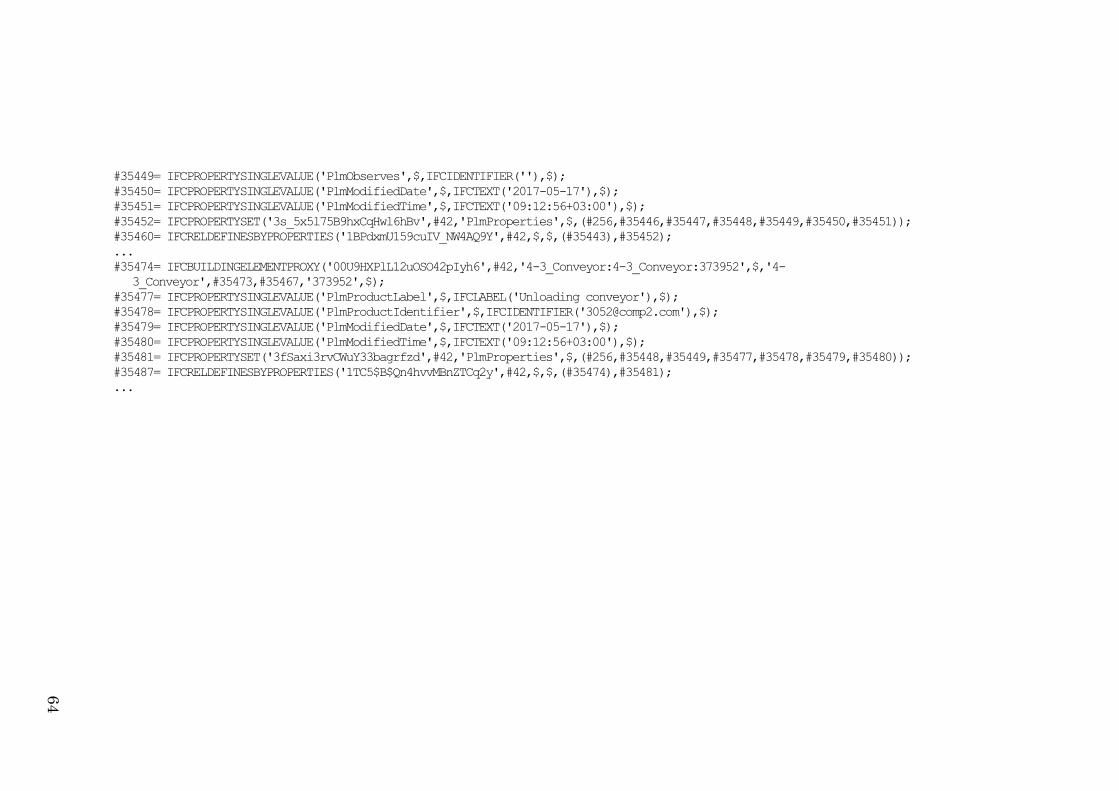
#35449= IFCPROPERTYSINGLEVALUE('PlmObserves',$,IFCIDENTIFIER(''),$);
#35450= IFCPROPERTYSINGLEVALUE('PlmModifiedDate',$,IFCTEXT('2017-05-17'),$);
#35451= IFCPROPERTYSINGLEVALUE('PlmModifiedTime',$,IFCTEXT('09:12:56+03:00'),$);
#35452= IFCPROPERTYSET('3s_5x5l75B9hxCqHwl6hBv',#42,'PlmProperties',$,(#256,#35446,#35447,#35448,#35449,#35450,#35451));
#35460= IFCRELDEFINESBYPROPERTIES('1BPdxmU159cuIV_NW4AQ9Y',#42,$,$,(#35443),#35452);
...
#35474= IFCBUILDINGELEMENTPROXY('00U9HXPlL12uOSO42pIyh6',#42,'4-3_Conveyor:4-3_Conveyor:373952',$,'4-
3_Conveyor',#35473,#35467,'373952',$);
#35477= IFCPROPERTYSINGLEVALUE('PlmProductLabel',$,IFCLABEL('Unloading conveyor'),$);
#35478= IFCPROPERTYSINGLEVALUE('PlmProductIdentifier',$,IFCIDENTIFIER('[email protected]'),$);
#35479= IFCPROPERTYSINGLEVALUE('PlmModifiedDate',$,IFCTEXT('2017-05-17'),$);
#35480= IFCPROPERTYSINGLEVALUE('PlmModifiedTime',$,IFCTEXT('09:12:56+03:00'),$);
#35481= IFCPROPERTYSET('3fSaxi3rvCWuY33bagrfzd',#42,'PlmProperties',$,(#256,#35448,#35449,#35477,#35478,#35479,#35480));
#35487= IFCRELDEFINESBYPROPERTIES('1TC5$B$Qn4hvvMBnZTCq2y',#42,$,$,(#35474),#35481);
...
64


