
LLiiqquuiidd CCrryyssttaalllliinnee PPoollyymmeerr
UUsseerr’’ss mmaannuuaall ffoorr SSuummiikkaassuuppeerr LLCCPP
vveerrssiioonn 33..11
Electronic Materials Div.
- ii -
Version History
ver. 1.0 5 February, 1996
ver. 2.0 27 July, 1998
ver. 2.5 25 May, 1999
ver.2.6 18 January, 2002
ver. 2.6.1 6 February, 2002
ver. 2.7 27 May, 2004
ver. 3.0 30 May, 2006
ver. 3.1 11 December, 2006 1996 by Sumitomo Chemical Co.,Ltd. Electronic Materials Div., Tsukuba R&D Center.
6 Kitahara, Tsukuba, Ibaraki, JAPAN 300-3294 tel: +81-29-864-4177 fax: +81-29-864-4745 http://www.sumitomo-chem.co.jp/sep/english/
Copyright Notice All Rights Reserved at Sumitomo Chemical Co., Ltd., Tokyo, Japan. Reproduction or translation of any part of this work without the express written permission of the copyright holder is unlawful. Requests for permission and translation or electronic rights should be addressed to Sumitomo Chemical Co., Ltd. at the address above. Disclaimer This document is designed to provide information concerning engineering technology for injection molding of liquid crystalline polymer. It is provided with understanding that Sumitomo Chemical Co., Ltd. is not engaged in no infringement of the intellectual property of the third parties during enforcing, applying, processing, and using all information described in this document.
.Liquid Crystalline Polymer
- iii -
<contents> 1. Introduction of liquid crystalline polymer
1-1 General properties of LCP 1-2 Thermal resistance 1-3 Moldability 1-4 Mechanical properties 1-5 Anisotropy 1-6 Market situation of liquid crystalline polymer 1-7 Conclusion
1 1 7 10 11 13 14 16
2. Application of for liquid crystalline polymer and its technology 2-1 Connector for PC, mobile, digital camera, etc. (1) Surface-Mount Technology (SMT) (2) Relationship between compound formulation and warpage 2-2 Bobbin for back-light transformer of LCD (1) Proceeding of the back-light system of LCD (2) Requirement for the inverter bobbin 2-3 OPU(Optical Pick-Up) actuator bobbin for CD-ROM, DVD, etc. (1) Requirement for OPU actuator bobbin (2) Relationship between modulus and thermal resistance
17 17 17 18 21 21 21 23 23 24
3. Injection molding technology for liquid crystalline polymer 3-1 Control System of Injection Process
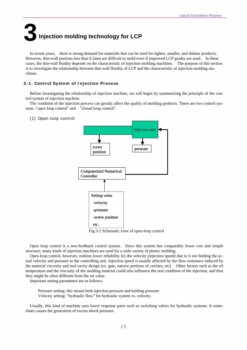
(1) Open loop control (2) Closed loop control
3-2 Thin-wall fluidity of LCP and characteristic of injection machine (1) Experiment (2) Result 3-3 Flow hesitation (1) What is “Flow Hesitation”? (2) Flow behavior of LCP 3-4 Metering of LCP (1) Principle of unstable metering (2) Solution of unstable metering
25 25 26 27 27 29 32 32 32 35 35 37
4. Improvement of warpage 4-1. Theoretical background of the warpage problem 4-2. Relationship between warpage and flow pattern
4-3. Relationship between the depth of core-out and the warpage 4-4. Case study
a) Board to board connector (0.5mm pitch) b) S/O DIMM c) PGA socket
39 39 41 44 46 46 46 48
5. Trouble shooting during injection molding 5-1 Outline for trouble shooting 5-2 Itemized discussion 5-3 Black spec -burning & carbonizing- 5-4 Blister & Bubble -classification & improvement-
(1) Comparison between “blister” and “bubble” (2) Reduction of the blister at soldering
a. Effect of moisture
50 50 52 53 54 54 54 55
- iv -
b. Retention of resin at the inside of injection machine c. Temperature settings of injection machine
~Difference between setting value and real resin temperature~ d. Relation between retention of LCP in cylinder and blister e. Unbalance between cylinder size and molding volume f. Purging method of Sumikasuper LCP
(3)Reduction of the bubble after molding a. Dragging of the air into the melt
b. Suitable injection condition c. Suitable cavity design
5-5 Crack (1) Cracking problem for Coil Bobbin (2) Side-wall cracking for Case part (3) Weld crack at the hole of Board to Board Connector
5-6 Flash 5-7 Flow mark 5-8 Metering 5-9 Short-shot 5-10 Sticking 5-11 Warpage
57 58
60 61 62 65 65 65 65 68 68 69 70 73 74 75 76 79 80
Reference 81
Liquid Crystalline Polymer
1
P reface
This booklet was originally planned to provide the presentation to molding engineers of our customers, because there was little literature or references about improvement and solution of molding problems for Liquid Crystalline Polymer (designated as LCP hereafter).
In early 1990s, it was a period of actual growth of thermotropic LCP industry for electric and electronic parts such as connectors, relays or coil bobbins for personal computers, mobile phones or digital cameras, etc. It was also the same movement of developing the new industry for IT business. Many componies of this business area have wished to use this eccentric polymer for such new products, however, sometimes they faced several molding problems. It seems that the behavior of LCP is very different from conventional engineering plastic, so sometimes molding engineers found it unmanageable.
The word of LCP is attractive and many researchers have worked about this region. However, almost all result of such works merely provided the discussion between theoretical back-ground and obtained data, or disclosed some of interesting phenomena during molding, such as “relationship between shear rate and apparent viscosity”, “effect of sta-tistic orientation to morphology”, etc. Those data or information, indeed, are very useful for researching or developing of new material based on LCP by specialists of polymer chemistry.
On the other hand, there are many useful and excellent literatures about plastic processing. Such literatures disclose not only principle of the mechanism or theoretical background of processing, but also the reason of molding trouble and its solution. However, such current knowledge sometimes prevents understanding the behavior of LCP and causes misunderstanding of improving immediate problem or hides the actual reason from the engineer.
In view of above situation, the first step of this booklet gave suggestions or solutions to solve molding trouble of LCP and to help understanding of LCP behavior. Thereafter we filled more contents of useful information over 10 years and it becomes workable brochure for not only experts but also beginners of LCP molding.
The 1st section expresses chemical and physical properties of LCP which will become the basic to understand LCP
behavior theoretically. It also discloses the market situation of LCP industry. The 2nd section discloses examples of LCP application and concept for electric and electronic parts. It will help you
when you choose more suitable grade for your applications or items. The 3rd section shows a methodology from a little different point of view. This section discloses that the performance
and specification of injection molding machine are also very important for LCP molding. It tends to be ignore, but it sometimes influences whether you obtain molding part successfully or not.
The 4th section indicates several know-how to solve warpage problem for connectors with actual examples. This in-formation will help you to develop the latest precision connectors or such electric and electronic parts successfully.
The last section, 5th is the most important section when you suffer the molding trouble. This section covers almost whole solution during using LCP.
December, 2006
Electronic Materials division Sumitomo Chemical Co., Ltd.
Liquid Crystalline Polymer
1
Liquid crystalline polymers (LCPs) are widely used in many types of electric and electronic parts due to their supe-
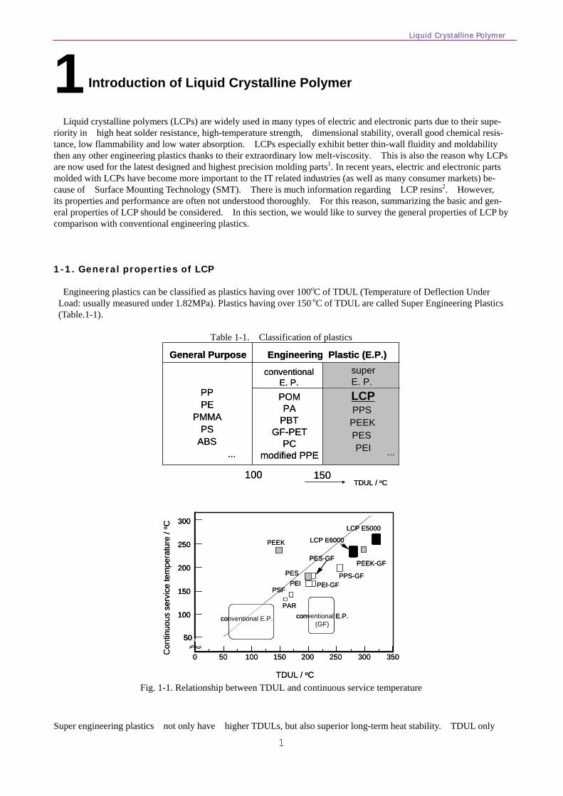
riority in high heat solder resistance, high-temperature strength, dimensional stability, overall good chemical resis-tance, low flammability and low water absorption. LCPs especially exhibit better thin-wall fluidity and moldability then any other engineering plastics thanks to their extraordinary low melt-viscosity. This is also the reason why LCPs are now used for the latest designed and highest precision molding parts1. In recent years, electric and electronic parts molded with LCPs have become more important to the IT related industries (as well as many consumer markets) be-cause of Surface Mounting Technology (SMT). There is much information regarding LCP resins2. However, its properties and performance are often not understood thoroughly. For this reason, summarizing the basic and gen-eral properties of LCP should be considered. In this section, we would like to survey the general properties of LCP by comparison with conventional engineering plastics. 1-1. General properties of LCP Engineering plastics can be classified as plastics having over 100oC of TDUL (Temperature of Deflection Under Load: usually measured under 1.82MPa). Plastics having over 150 oC of TDUL are called Super Engineering Plastics (Table.1-1).
Table 1-1. Classification of plastics
General Purpose Engineering Plastic (E.P.)
conventional E. P.
superE. P.
PPPE
PMMAPS
ABS...
POM
PCmodified PPE
PAPBT
GF-PET
LCP
PEEKPES
PPS
PEI ...
TDUL / oC100 150
General Purpose Engineering Plastic (E.P.)
conventional E. P.
superE. P.
PPPE
PMMAPS
ABS...
POM
PCmodified PPE
PAPBT
GF-PET
LCP
PEEKPES
PPS
PEI ...
TDUL / oC100 150
350300250200150100500
50
100
150
200
250
300LCP E5000
LCP E6000PEEK
PEEK-GF
PPS-GF
PES-GF
PES
PSF
PAR
conventional E.P. conventional E.P.(GF)
PEI PEI-GF
TDUL / oC
Con
tinuo
us s
ervi
ce te
mpe
ratu
re /
o C
350300250200150100500
50
100
150
200
250
300
50
100
150
200
250
300LCP E5000
LCP E6000PEEK
PEEK-GF
PPS-GF
PES-GF
PES
PSF
PAR
conventional E.P. conventional E.P.(GF)
PEI PEI-GF
TDUL / oC
Con
tinuo
us s
ervi
ce te
mpe
ratu
re /
o C
Fig. 1-1. Relationship between TDUL and continuous service temperature
Super engineering plastics not only have higher TDULs, but also superior long-term heat stability. TDUL only
1 Introduction of Liquid Crystalline Polymer
1 Introduction of liquid crystalline polymer
2
indicates short-term heat stability. Fig. 1-1 indicates the relationship between TDUL and continuous service tempera-ture. This parameter equals long-term heat stability and is measured under the conditions described in UL 746B. As shown in the figure, super engineering plastics indicate both higher TDUL and over 200 oC of continuous service temperature. This allows these plastics to be suitable for SMT soldering or other high heat treatments (in general, SMT soldering temperature is over 220oC). Conventional engineering plastics will exhibit similar TDULs when reinforced by glass or fibers, and thus perceived higher heat resistance. It should be noted; however, that these polymers do not have as high of continuous service temperature resistance. This means that conventional engineer-ing plastics are not suitable for high heat treatment such as SMT soldering.
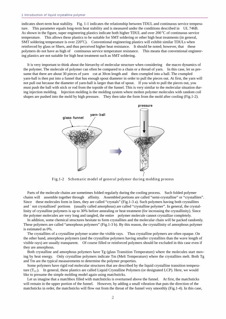
It is very important to think about the hierarchy of molecular structure when considering the macro dynamics of
the polymer. The molecule of polymer can often be compared to a chain or a thread of yarn. In this case, let us pre-sume that there are about 30 pieces of yarn cut at 30cm length and then crumpled into a ball. The crumpled yarn-ball is then put into a funnel that has enough spout diameter in order to pull the pieces out. At first, the yarn will not pull out because the diameter of yarn-ball is larger than that of spout. If you wish to pull the pieces out, you must push the ball with stick or rod from the topside of the funnel. This is very similar to the molecular situation dur-ing injection molding. Injection molding is the molding system where molten polymer molecules with random coil shapes are pushed into the mold by high pressure. They then take the form from the mold after cooling (Fig.1-2).
pressure
yarn-ballglass-funnel
pressure
yarn-ballglass-funnel
Fig.1-2 Schematic model of general polymer during molding process
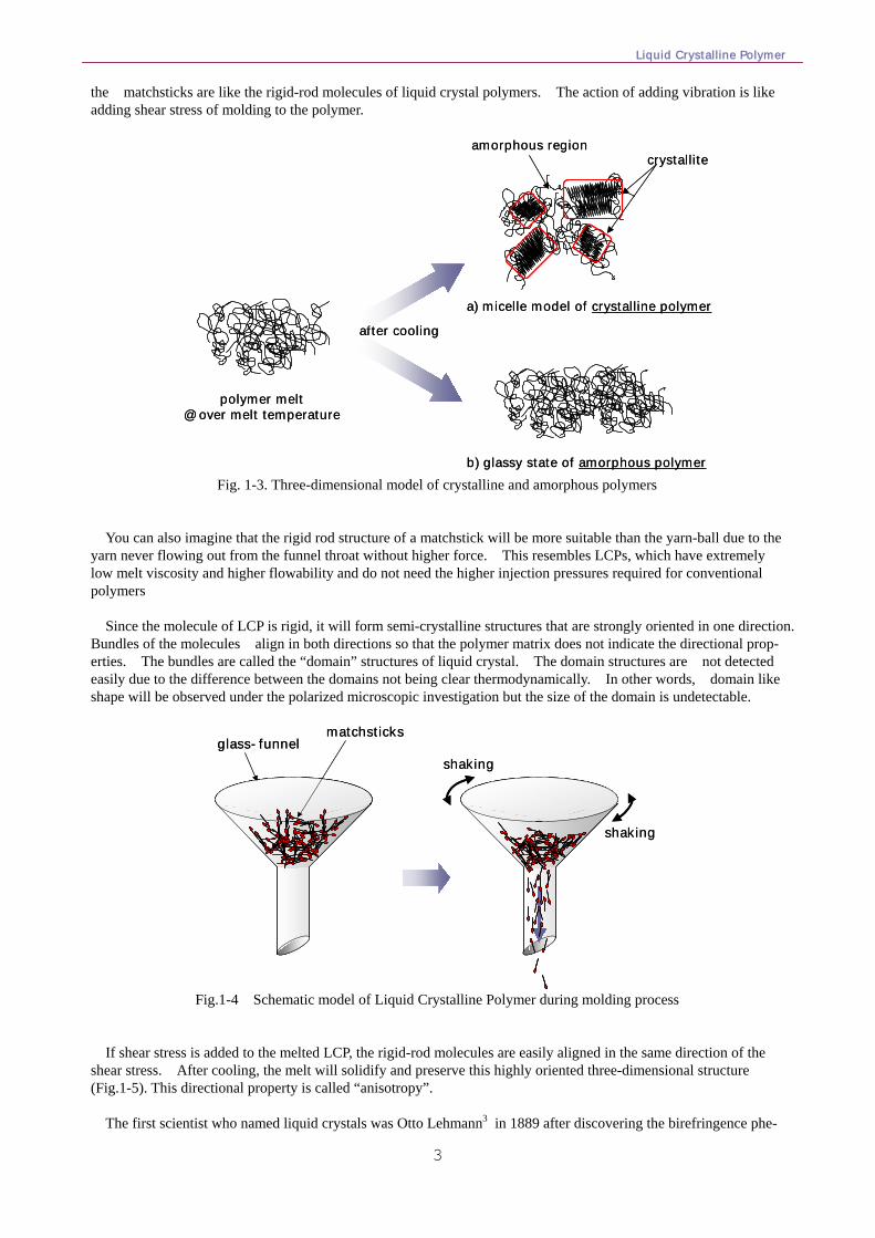
Parts of the molecule chains are sometimes folded regularly during the cooling process. Such folded polymer chains will assemble together through affinity. Assembled portions are called “semi-crystalline” or “crystallites”. Since these molecules form in lines, they are called “crystals” (Fig.1-3 a). Such polymers having both crystallites and ` not crystallized` portions (usually called amorphous) are called “crystalline polymer”. In general, the crystal-linity of crystalline polymers is up to 30% before annealing or heat treatment (for increasing the crystallinity). Since the polymer molecules are very long and tangled, the entire polymer molecule cannot crystallize completely.
In addition, some chemical structures hesitate to form crystallites and the molecular chain will be packed randomly. These polymers are called “amorphous polymers” (Fig.1-3 b). By this reason, the crystallinity of amorphous polymer is estimated as 0%.
The crystallites of a crystalline polymer scatter the visible rays. Thus crystalline polymers are often opaque. On the other hand, amorphous polymers (and the crystalline polymers having smaller crystallites than the wave length of visible rays) are usually transparent. Of course filled or reinforced polymers should be excluded in this case even if they are amorphous.
Both crystalline and amorphous polymers have Tg (glass Transition Temperature) where the molecules start mov-ing by heat energy. Only crystalline polymers indicate Tm (Melt Temperature) where the crystallites melt. Both Tg and Tm are the typical measurements to determine the polymer properties.
Some polymers have rigid rod molecular structures that are described by the liquid crystalline transition tempera-ture (TLC). In general, these plastics are called Liquid Crystalline Polymers (or designated LCP). Here, we would like to presume the simple molding model again using matchsticks.
Let us imagine that a matchbox filled with matchsticks is overturned above the funnel. At first, the matchsticks will remain in the upper portion of the funnel. However, by adding a small vibration that puts the direction of the matchsticks in order, the matchsticks will flow out from the throat of the funnel very smoothly (Fig.1-4). In this case,
Liquid Crystalline Polymer
3
the matchsticks are like the rigid-rod molecules of liquid crystal polymers. The action of adding vibration is like adding shear stress of molding to the polymer.
crystalliteamorphous region
a) micelle model of crystalline polymer
b) glassy state of amorphous polymer
polymer melt@ over melt temperature
after cooling
crystalliteamorphous region
a) micelle model of crystalline polymer
b) glassy state of amorphous polymer
polymer melt@ over melt temperature
after cooling
Fig. 1-3. Three-dimensional model of crystalline and amorphous polymers
You can also imagine that the rigid rod structure of a matchstick will be more suitable than the yarn-ball due to the yarn never flowing out from the funnel throat without higher force. This resembles LCPs, which have extremely low melt viscosity and higher flowability and do not need the higher injection pressures required for conventional polymers
Since the molecule of LCP is rigid, it will form semi-crystalline structures that are strongly oriented in one direction.
Bundles of the molecules align in both directions so that the polymer matrix does not indicate the directional prop-erties. The bundles are called the “domain” structures of liquid crystal. The domain structures are not detected easily due to the difference between the domains not being clear thermodynamically. In other words, domain like shape will be observed under the polarized microscopic investigation but the size of the domain is undetectable.
matchsticks
glass-funnelshaking
shaking
matchsticksglass-funnel
shaking
shaking
Fig.1-4 Schematic model of Liquid Crystalline Polymer during molding process
If shear stress is added to the melted LCP, the rigid-rod molecules are easily aligned in the same direction of the shear stress. After cooling, the melt will solidify and preserve this highly oriented three-dimensional structure (Fig.1-5). This directional property is called “anisotropy”.
The first scientist who named liquid crystals was Otto Lehmann3 in 1889 after discovering the birefringence phe-
1 Introduction of liquid crystalline polymer
4
nomenon by Friedrich Reinitzer4 in 1888. The low molecular weight liquid crystals; however, demonstrated rela-tively different history with polymer liquid crystals. Such investigations have helped to develop the current LCD (Liquid Crystal Display) etc. The first notable work of polymer liquid crystals started from the pioneering study by Onsager, Ishihara, and Flory5. Flory predicted lyotropic liquid crystals that indicate liquid crystallinity in dilute so-lutions. This stimulated many researchers’ interest, and now there is much literature about liquid crystals6.
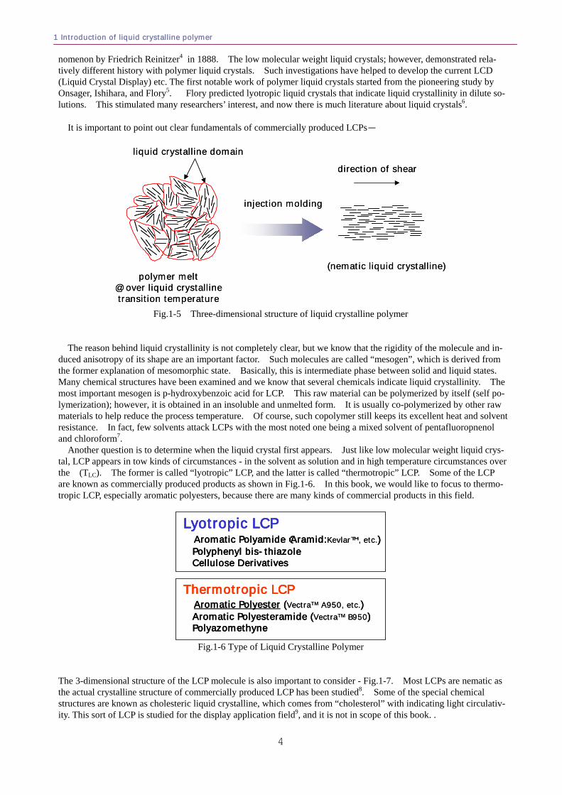
It is important to point out clear fundamentals of commercially produced LCPs-
polymer melt@ over liquid crystallinetransition temperature
injection molding
direction of shear
(nematic liquid crystalline)
liquid crystalline domain
polymer melt@ over liquid crystallinetransition temperature
injection molding
direction of shear
(nematic liquid crystalline)
liquid crystalline domain
Fig.1-5 Three-dimensional structure of liquid crystalline polymer
The reason behind liquid crystallinity is not completely clear, but we know that the rigidity of the molecule and in-duced anisotropy of its shape are an important factor. Such molecules are called “mesogen”, which is derived from the former explanation of mesomorphic state. Basically, this is intermediate phase between solid and liquid states. Many chemical structures have been examined and we know that several chemicals indicate liquid crystallinity. The most important mesogen is p-hydroxybenzoic acid for LCP. This raw material can be polymerized by itself (self po-lymerization); however, it is obtained in an insoluble and unmelted form. It is usually co-polymerized by other raw materials to help reduce the process temperature. Of course, such copolymer still keeps its excellent heat and solvent resistance. In fact, few solvents attack LCPs with the most noted one being a mixed solvent of pentafluoropnenol and chloroform7.
Another question is to determine when the liquid crystal first appears. Just like low molecular weight liquid crys-tal, LCP appears in tow kinds of circumstances - in the solvent as solution and in high temperature circumstances over the (TLC). The former is called “lyotropic” LCP, and the latter is called “thermotropic” LCP. Some of the LCP are known as commercially produced products as shown in Fig.1-6. In this book, we would like to focus to thermo-tropic LCP, especially aromatic polyesters, because there are many kinds of commercial products in this field.
Lyotropic LCP Aromatic Polyamide(Aramid:KevlarTM, etc.)Polyphenyl bis-thiazoleCellulose Derivatives
Thermotropic LCPAromatic Polyester (VectraTM A950, etc.)Aromatic Polyesteramide (VectraTM B950)Polyazomethyne
Lyotropic LCP Aromatic Polyamide(Aramid:KevlarTM, etc.)Polyphenyl bis-thiazoleCellulose Derivatives
Thermotropic LCPAromatic Polyester (VectraTM A950, etc.)Aromatic Polyesteramide (VectraTM B950)Polyazomethyne
Fig.1-6 Type of Liquid Crystalline Polymer
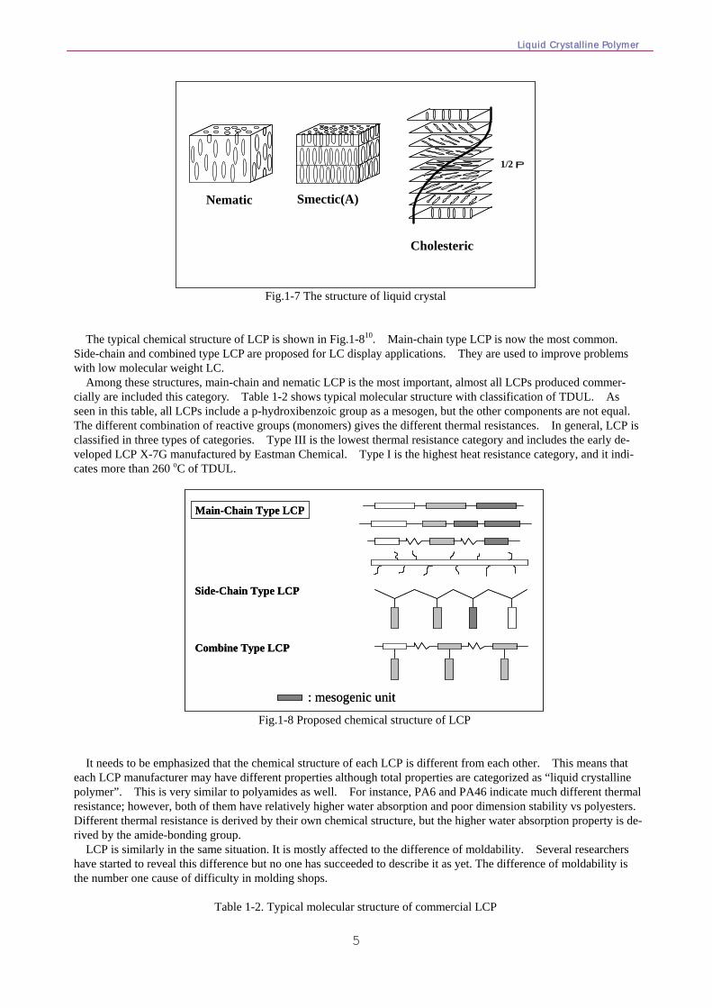
The 3-dimensional structure of the LCP molecule is also important to consider - Fig.1-7. Most LCPs are nematic as the actual crystalline structure of commercially produced LCP has been studied8. Some of the special chemical structures are known as cholesteric liquid crystalline, which comes from “cholesterol” with indicating light circulativ-ity. This sort of LCP is studied for the display application field9, and it is not in scope of this book. .
Liquid Crystalline Polymer
5
1/2P
Nematic Smectic(A)
Cholesteric
1/2P
Nematic Smectic(A)
Cholesteric
Fig.1-7 The structure of liquid crystal
The typical chemical structure of LCP is shown in Fig.1-810. Main-chain type LCP is now the most common. Side-chain and combined type LCP are proposed for LC display applications. They are used to improve problems with low molecular weight LC.
Among these structures, main-chain and nematic LCP is the most important, almost all LCPs produced commer-cially are included this category. Table 1-2 shows typical molecular structure with classification of TDUL. As seen in this table, all LCPs include a p-hydroxibenzoic group as a mesogen, but the other components are not equal. The different combination of reactive groups (monomers) gives the different thermal resistances. In general, LCP is classified in three types of categories. Type III is the lowest thermal resistance category and includes the early de-veloped LCP X-7G manufactured by Eastman Chemical. Type I is the highest heat resistance category, and it indi-cates more than 260 oC of TDUL.
Main-Chain Type LCP
Side-Chain Type LCP
Combine Type LCP
: mesogenic unit
Main-Chain Type LCP
Side-Chain Type LCP
Combine Type LCP
: mesogenic unit
Fig.1-8 Proposed chemical structure of LCP It needs to be emphasized that the chemical structure of each LCP is different from each other. This means that
each LCP manufacturer may have different properties although total properties are categorized as “liquid crystalline polymer”. This is very similar to polyamides as well. For instance, PA6 and PA46 indicate much different thermal resistance; however, both of them have relatively higher water absorption and poor dimension stability vs polyesters. Different thermal resistance is derived by their own chemical structure, but the higher water absorption property is de-rived by the amide-bonding group.
LCP is similarly in the same situation. It is mostly affected to the difference of moldability. Several researchers have started to reveal this difference but no one has succeeded to describe it as yet. The difference of moldability is the number one cause of difficulty in molding shops.
Table 1-2. Typical molecular structure of commercial LCP
1 Introduction of liquid crystalline polymer
6
Type Molecular Structure TDUL Example
Type Ⅰ >260oC SUMIKASUPERSUMIKASUPERXydar
Type II 210 - 260oC Vectra
O CO
O O C COO
OCOO C
O
Type III C COO
O CO
OCH2CH2O <210oC Rodrun
Novaccurate
PETp-hydroxybenzoic group
Type Molecular Structure TDUL Example
Type Ⅰ >260oC SUMIKASUPERSUMIKASUPERXydar
Type II 210 - 260oC Vectra
O CO
O O C COO
OCOO C
O
Type III C COO
O CO
OCH2CH2O <210oC Rodrun
Novaccurate
PET
Type Molecular Structure TDUL Example
Type Ⅰ >260oC SUMIKASUPERSUMIKASUPERXydar
Type II 210 - 260oC Vectra
O CO
O O C COO
OCOO C
O
O CO
O O C COO
OCOO C
O
Type III C COO
O CO
OCH2CH2O <210oC Rodrun
Novaccurate
PETp-hydroxybenzoic group
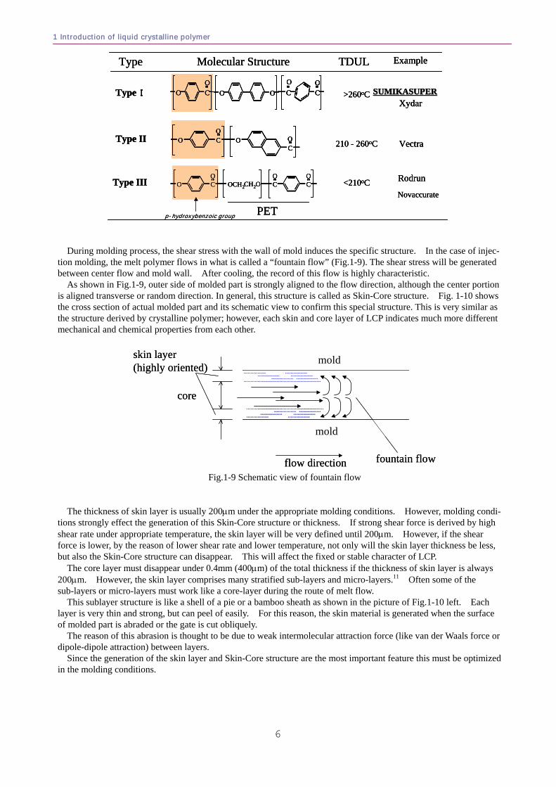
During molding process, the shear stress with the wall of mold induces the specific structure. In the case of injec-tion molding, the melt polymer flows in what is called a “fountain flow” (Fig.1-9). The shear stress will be generated between center flow and mold wall. After cooling, the record of this flow is highly characteristic.
As shown in Fig.1-9, outer side of molded part is strongly aligned to the flow direction, although the center portion is aligned transverse or random direction. In general, this structure is called as Skin-Core structure. Fig. 1-10 shows the cross section of actual molded part and its schematic view to confirm this special structure. This is very similar as the structure derived by crystalline polymer; however, each skin and core layer of LCP indicates much more different mechanical and chemical properties from each other.
skin layer(highly oriented)
core
flow direction fountain flow
mold
moldskin layer(highly oriented)
core
flow direction fountain flow
mold
mold
Fig.1-9 Schematic view of fountain flow
The thickness of skin layer is usually 200μm under the appropriate molding conditions. However, molding condi-
tions strongly effect the generation of this Skin-Core structure or thickness. If strong shear force is derived by high shear rate under appropriate temperature, the skin layer will be very defined until 200μm. However, if the shear force is lower, by the reason of lower shear rate and lower temperature, not only will the skin layer thickness be less, but also the Skin-Core structure can disappear. This will affect the fixed or stable character of LCP.
The core layer must disappear under 0.4mm (400μm) of the total thickness if the thickness of skin layer is always 200μm. However, the skin layer comprises many stratified sub-layers and micro-layers.11 Often some of the sub-layers or micro-layers must work like a core-layer during the route of melt flow.
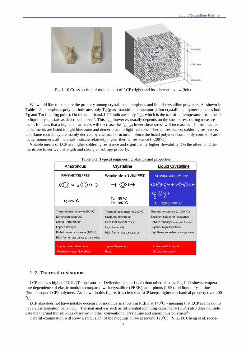
This sublayer structure is like a shell of a pie or a bamboo sheath as shown in the picture of Fig.1-10 left. Each layer is very thin and strong, but can peel of easily. For this reason, the skin material is generated when the surface of molded part is abraded or the gate is cut obliquely.
The reason of this abrasion is thought to be due to weak intermolecular attraction force (like van der Waals force or dipole-dipole attraction) between layers.
Since the generation of the skin layer and Skin-Core structure are the most important feature this must be optimized in the molding conditions.
Liquid Crystalline Polymer
7
Fig.1-10 Cross section of molded part of LCP (right) and its schematic view (left)
We would like to compare the property among crystalline, amorphous and liquid crystalline polymers. As shown in Table 1-3, amorphous polymer indicates only Tg (glass-transition temperature), but crystalline polymer indicates both Tg and Tm (melting point). On the other hand, LCP indicates only TLC, which is the transition temperature from solid to liquid crystal state as described above12. This TLC, however, usually depends on the shear stress during measure-ment. It means that a higher shear stress will decrease the TLC, and lower shear stress will increase it. In the attached table, merits are listed in light blue zone and demerits are in light red zone. Thermal resistance, soldering resistance, and flame retardancy are mainly derived by chemical structure. Since the listed polymers commonly consist of aro-matic monomers, all materials indicate relatively higher thermal resistance (>200oC).
Notable merits of LCP are higher soldering resistance and significantly higher flowability. On the other hand de-merits are lower weld strength and strong anisotropy property.
Table 1-3. Typical engineering plastics and properties
Thermal resistance (to 200 oC)
Dimension accuracy
Creep Performance
Impact strength
Boiled water resistance (160 oC)
High flame retardancy (V-0 @ 0.4mmt)
Thermal resistance (to 240 oC)
Soldering resistance
Excellent solvent resist.
High flowability
High flame retardancy (V-0)
Liquid CrystallineLiquid CrystallineCrystallineAmorphous
( SO O )2
SUMIKAEXCEL® PES
( )S
Polyphenylene Sulfid (PPS) SUMIKASUPERSUMIKASUPER®® LCPLCP
OOC O O
CO
C )
Tg 225 oCTg 85 oCTm 285 oC
Thermal resistance (to 260 oC)
Excellent soldering resistance
Solvent stability (except alkali & steam)
Superior high flowability
High flame retardancy (V-0 @0.3mmt)
TLC 320 to 400 oC
(O
( ) ( )
Higher Degassing
Flash
Higher water absorption
Relatively lower flowability
Lower weld strength
Strong anisotropy
Thermal resistance (to 200 oC)
Dimension accuracy
Creep Performance
Impact strength
Boiled water resistance (160 oC)
High flame retardancy (V-0 @ 0.4mmt)
Thermal resistance (to 240 oC)
Soldering resistance
Excellent solvent resist.
High flowability
High flame retardancy (V-0)
Liquid CrystallineLiquid CrystallineCrystallineAmorphous
( SO O )2
SUMIKAEXCEL® PES
( )S
Polyphenylene Sulfid (PPS) SUMIKASUPERSUMIKASUPER®® LCPLCP
OOC O O
CO
C )
Tg 225 oCTg 85 oCTm 285 oC
Thermal resistance (to 260 oC)
Excellent soldering resistance
Solvent stability (except alkali & steam)
Superior high flowability
High flame retardancy (V-0 @0.3mmt)
TLC 320 to 400 oC
(O
( ) ( )
Higher Degassing
Flash
Higher water absorption
Relatively lower flowability
Lower weld strength
Strong anisotropy 1-2. Thermal resistance LCP realizes higher TDUL (Temperature of Deflection Under Load) than other plastics. Fig.1-11 shows tempera-
ture dependence of elastic modulus compared with crystalline (PEEK), amorphous (PES) and liquid crystalline (Sumikasuper LCP) polymers. As shown in this figure, it is clear that LCP keeps higher mechanical property over 200 oC.
LCP also does not have notable decrease of modulus as shown in PEEK at 140oC – meaning that LCP seems not to have glass transition behavior. Thermal analysis such as differential scanning calorimetry (DSC) also does not indi-cate the thermal transition as observed in other conventional crystalline and amorphous polymers13.
Careful examination will show a small slant of the modulus curve at around 120oC. S. Z. D. Cheng et al. recog-

1 Introduction of liquid crystalline polymer
8
nized that LCP having several kinds of chemical structures would indicate two different crystal structures in the tem-perature range of solid to nematic through annealing treatment14. Other researchers have since expanded the region of study for several chemical structures of LCP15. Some researchers have found that LCPs having Vectra like chemical structure have 2 or 3 kinds of relaxation. These are named as α, β- and γ-relaxation, which are very similar with conventional polymers16,17. In this case, a-relaxation is very similar to conventional glass transition temperature (Tg). This change seems very similar with the change at Tg of crystalline polymer. In fact, a very small and dull peak is sometimes observed in tan δ curve of dynamic mechanical analysis at the same temperature region.
4003002001000107
108
109
1010
1011
Temperature /oC
G (d
yne/
cm2 )
Liquid Crystalline (Sumikasuper® LCP)
Amorphous(PES)
Crystalline(PEEK)
Tg: 143oC
Tm: 334oC
Tg: 225oC TLC: 300 - 380oC(according to molecular structure)
4003002001000 4003002001000107
108
109
1010
1011
Temperature /oC
G (d
yne/
cm2 )
Liquid Crystalline (Sumikasuper® LCP)
Amorphous(PES)
Crystalline(PEEK)
Tg: 143oC
Tm: 334oC
Tg: 225oC TLC: 300 - 380oC(according to molecular structure)
Fig.1-11 Temperature dependence of modulus
This means that it is not usually necessary to think about the Tg of LCP. This is also why any mold temperature
up to molding temperature can be chosen for LCPs. For instance, the mold temperature of PEEK should be set at over 160oC, because its Tg is 144oC and higher than this temperature is necessary to achieve higher crystallinity after cooling. In this meaning, mold temperature has little impact on LCP properties. However, we should notice that at a little performance change occurred at Tg, which is pointed out by Ward et al15.
Furthermore, LCP`s decomposition temperature is over 500 oC, which is much higher than most other plastics (Fig.1-12). This helps LCP to have very low out-gassing. This is due to the origin of outgas is usually in the heat-ing of the decomposed material.
-40
-30
-20
-10
0
10
200 300 400 500 600 700Temperature /oC
Wei
ght L
oss (
%)
In N2 Liquid Crystalline(Sumikasuper® LCP)
PPSPBT
-40
-30
-20
-10
0
10
200 300 400 500 600 700Temperature /oC
Wei
ght L
oss (
%)
In N2 Liquid Crystalline(Sumikasuper® LCP)
PPSPBT
Fig.1-12 Thermal gravimetric analysis
For the same reason, LCP is inertly flame retardant. Hence, there is no possibility of generating halogen material during molding by decomposition.
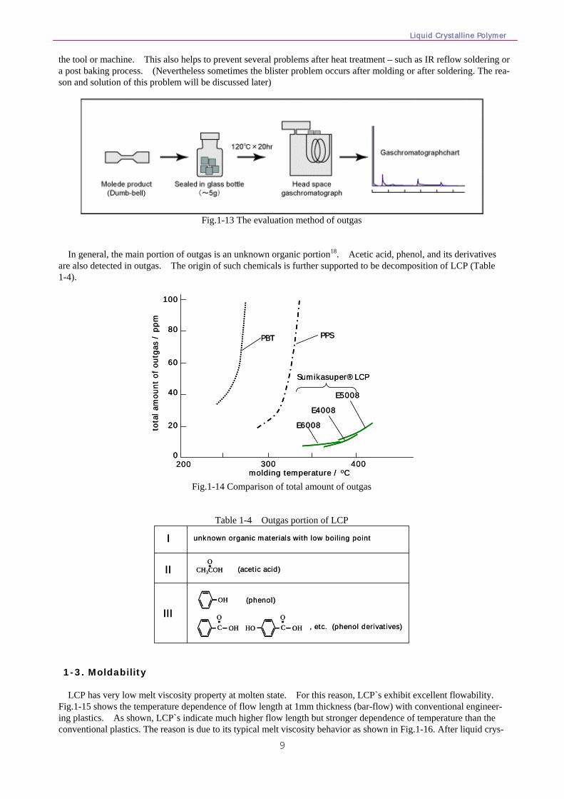
We should also examine the comparison of out-gassing between conventional plastics. Since trapping the outgas during molding is difficult and inaccurate, we have carried out the evaluation under the 120oC, 20hrs conditions shown in Fig.1-13. The result is shown in Fig.1-14. As shown in the figure, LCP shows lower amount of outgas than conventional plastics. This is important for many applications (lighting, medical) and helps to avoid mold deposit on
Liquid Crystalline Polymer
9
the tool or machine. This also helps to prevent several problems after heat treatment – such as IR reflow soldering or a post baking process. (Nevertheless sometimes the blister problem occurs after molding or after soldering. The rea-son and solution of this problem will be discussed later)
Fig.1-13 The evaluation method of outgas
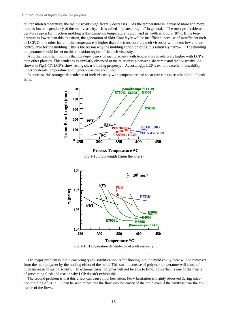
In general, the main portion of outgas is an unknown organic portion18. Acetic acid, phenol, and its derivatives are also detected in outgas. The origin of such chemicals is further supported to be decomposition of LCP (Table 1-4).
200 300 4000
20
40
60
80
100
tota
l am
ount
of o
utga
s /
ppm
molding temperature / oC
PPSPBT
E6008
E4008
E5008
Sumikasuper® LCP
200 300 4000
20
40
60
80
100
tota
l am
ount
of o
utga
s /
ppm
molding temperature / oC
PPSPBT
E6008
E4008
E5008
Sumikasuper® LCP
Fig.1-14 Comparison of total amount of outgas
Table 1-4 Outgas portion of LCP
OH
CO
OH CO
OHHO , etc. (phenol derivatives)
CH3COHO
unknown organic materials with low boiling point
(acetic acid)
(phenol)
I
II
IIIOH
CO
OH CO
OHHO , etc. (phenol derivatives)
CH3COHO
unknown organic materials with low boiling point
(acetic acid)
(phenol)
I
II
III
1-3. Moldability LCP has very low melt viscosity property at molten state. For this reason, LCP`s exhibit excellent flowability.
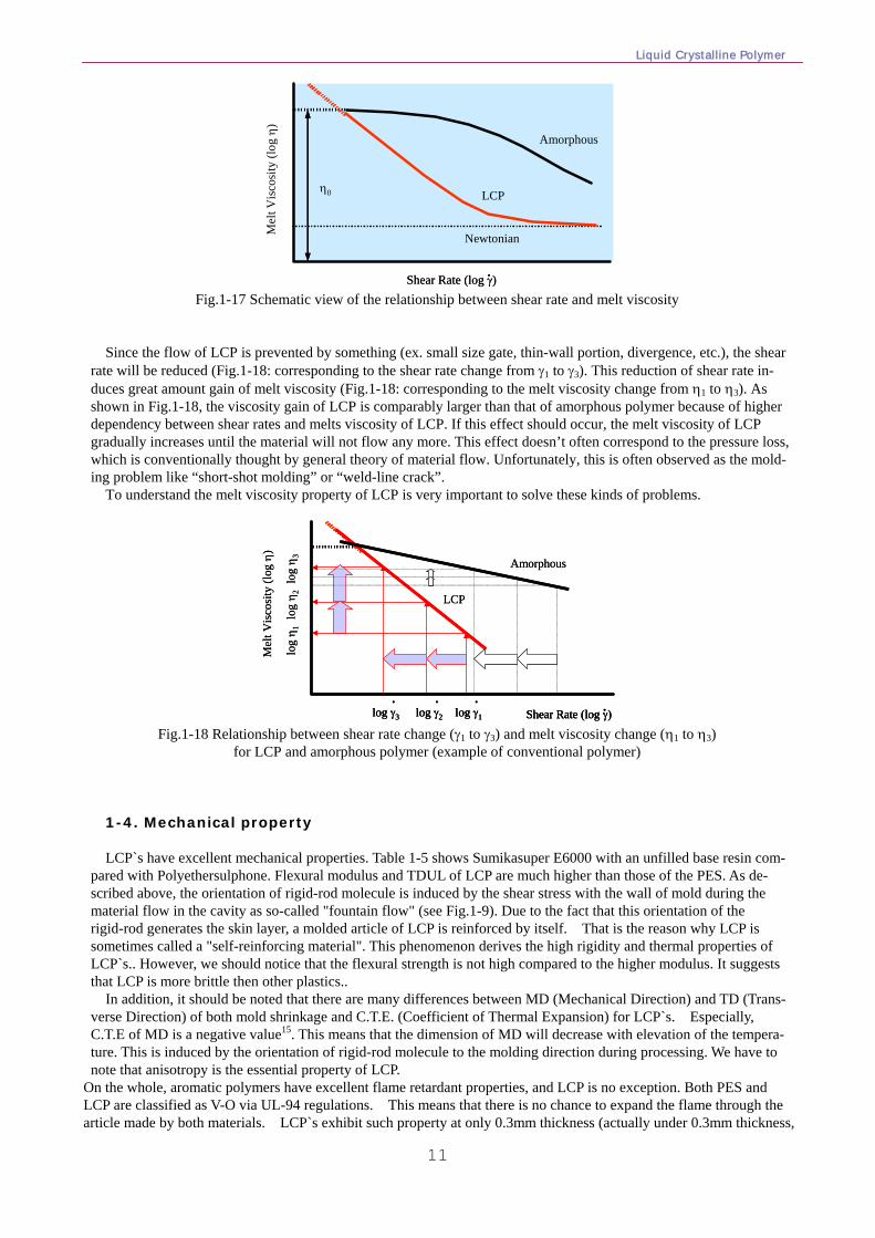
Fig.1-15 shows the temperature dependence of flow length at 1mm thickness (bar-flow) with conventional engineer-ing plastics. As shown, LCP`s indicate much higher flow length but stronger dependence of temperature than the conventional plastics. The reason is due to its typical melt viscosity behavior as shown in Fig.1-16. After liquid crys-
1 Introduction of liquid crystalline polymer
10
tal transition temperature, the melt viscosity significantly decreases. As the temperature is increased more and more, there is lower dependency of the melt viscosity. It is called "plateau region" in general. The most preferable tem-perature region for injection molding is this transition temperature region, and its width is around 10oC. If the tem-perature is lower than this transition, the generation of Skin-Core layer will be insufficient because of insufficient melt of LCP. On the other hand, if the temperature is higher than this transition, the melt viscosity will be too low and un-controllable for the molding. This is the reason why the molding condition of LCP is relatively narrow. The molding temperature should be set on this transition region of the melt viscosity.
A further important point is that the dependency of melt viscosity with temperature is relatively higher with LCP`s than other plastics. This tendency is similarly observed at the relationship between shear rate and melt viscosity. As shown in Fig.1-17, LCP`s show strong shear thinning property. Accordingly, LCP`s exhibit excellent flowability under moderate temperature and higher shear rate condition.
In contrast, this stronger dependence of melt viscosity with temperature and shear rate can cause other kind of prob-lems.
4504003503002500
100
200
300
400
500
Process Temperature /oC
1m
mtF
low
Len
gth
(mm
) E7006L E6008 E4008
E5008L
PEEK 380G
PEEK 450GL20PES 3600G
PES3601 GL20
PPS
PC
PET
(Sumikasuper® LCP)
450400350300250 4504003503002500
100
200
300
400
500
Process Temperature /oC
1m
mtF
low
Len
gth
(mm
) E7006L E6008 E4008
E5008L
PEEK 380G
PEEK 450GL20PES 3600G
PES3601 GL20
PPS
PC
PET
(Sumikasuper® LCP)
Fig.1-15 Flow length (1mm thickness)
450400350300250102
103
104
105
PPS
E6008
E5008E4008
E7006L
PEEK
η (p
oise
)
Temperature /oC
PES
PET
(Sumikasuper® LCP)
γ : 103 sec-1.
450400350300250 450400350300250102
103
104
105
PPS
E6008
E5008E4008
E7006L
PEEK
η (p
oise
)
Temperature /oC
PES
PET
(Sumikasuper® LCP)
γ : 103 sec-1.γ : 103 sec-1.
Fig.1-16 Temperature dependence of melt viscosity
The major problem is that it can bring quick solidification. After flowing into the mold cavity, heat will be removed
from the melt polymer by the cooling effect of the mold. This small decrease of polymer temperature will cause of huge increase of melt viscosity. In extreme cases, polymer will not be able to flow. This effect is one of the merits of preventing flash and reason why LCP doesn’t exhibit this.
The second problem is that this effect can cause flow hesitation. Flow hesitation is mainly observed during injec-tion molding of LCP. It can be seen to hesitate the flow into the cavity of the mold even if the cavity is near the en-trance of the flow..
Liquid Crystalline Polymer
11
Mel
t Vis
cosi
ty (l
og η
)
Newtonian
LCP
Shear Rate (log γ).Shear Rate (log γ).
Amorphous
η0
Fig.1-17 Schematic view of the relationship between shear rate and melt viscosity
Since the flow of LCP is prevented by something (ex. small size gate, thin-wall portion, divergence, etc.), the shear
rate will be reduced (Fig.1-18: corresponding to the shear rate change from γ1 to γ3). This reduction of shear rate in-duces great amount gain of melt viscosity (Fig.1-18: corresponding to the melt viscosity change from η1 to η3). As shown in Fig.1-18, the viscosity gain of LCP is comparably larger than that of amorphous polymer because of higher dependency between shear rates and melts viscosity of LCP. If this effect should occur, the melt viscosity of LCP gradually increases until the material will not flow any more. This effect doesn’t often correspond to the pressure loss, which is conventionally thought by general theory of material flow. Unfortunately, this is often observed as the mold-ing problem like “short-shot molding” or “weld-line crack”.
To understand the melt viscosity property of LCP is very important to solve these kinds of problems.
Mel
t Vis
cosi
ty (l
og η
)
Shear Rate (log γ).
LCP
Amorphous
log γ1
.log γ2
.log γ3
.
log
η 1lo
g η 2
log
η 3
Mel
t Vis
cosi
ty (l
og η
)
Shear Rate (log γ).Shear Rate (log γ).
LCP
Amorphous
log γ1
.log γ1
.log γ2
.log γ2
.log γ3
.log γ3
.
log
η 1lo
g η 2
log
η 3
Fig.1-18 Relationship between shear rate change (γ1 to γ3) and melt viscosity change (η1 to η3)
for LCP and amorphous polymer (example of conventional polymer) 1-4. Mechanical property LCP`s have excellent mechanical properties. Table 1-5 shows Sumikasuper E6000 with an unfilled base resin com-
pared with Polyethersulphone. Flexural modulus and TDUL of LCP are much higher than those of the PES. As de-scribed above, the orientation of rigid-rod molecule is induced by the shear stress with the wall of mold during the material flow in the cavity as so-called "fountain flow" (see Fig.1-9). Due to the fact that this orientation of the rigid-rod generates the skin layer, a molded article of LCP is reinforced by itself. That is the reason why LCP is sometimes called a "self-reinforcing material". This phenomenon derives the high rigidity and thermal properties of LCP`s.. However, we should notice that the flexural strength is not high compared to the higher modulus. It suggests that LCP is more brittle then other plastics..
In addition, it should be noted that there are many differences between MD (Mechanical Direction) and TD (Trans-verse Direction) of both mold shrinkage and C.T.E. (Coefficient of Thermal Expansion) for LCP`s. Especially, C.T.E of MD is a negative value15. This means that the dimension of MD will decrease with elevation of the tempera-ture. This is induced by the orientation of rigid-rod molecule to the molding direction during processing. We have to note that anisotropy is the essential property of LCP.
On the whole, aromatic polymers have excellent flame retardant properties, and LCP is no exception. Both PES and LCP are classified as V-O via UL-94 regulations. This means that there is no chance to expand the flame through the article made by both materials. LCP`s exhibit such property at only 0.3mm thickness (actually under 0.3mm thickness,
1 Introduction of liquid crystalline polymer
12
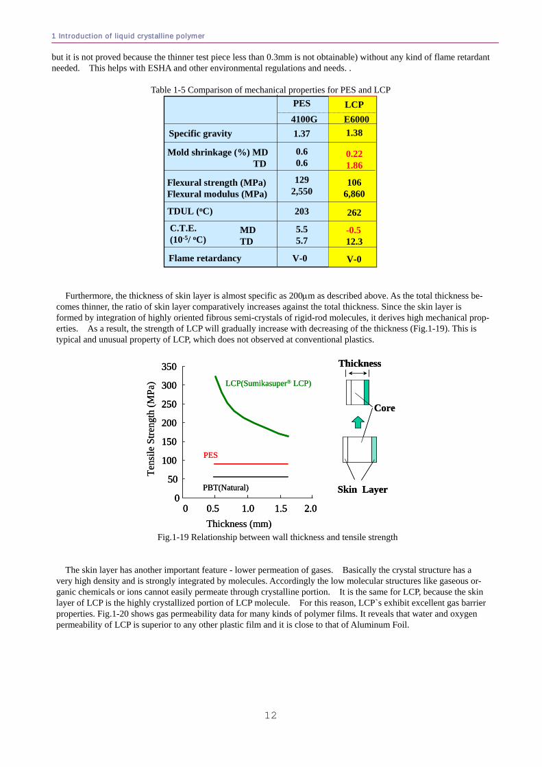
but it is not proved because the thinner test piece less than 0.3mm is not obtainable) without any kind of flame retardant needed. This helps with ESHA and other environmental regulations and needs. .
Table 1-5 Comparison of mechanical properties for PES and LCP PES
4100GSpecific gravity 1.37
Mold shrinkage (%) MDTD
0.60.6
Flexural strength (MPa)Flexural modulus (MPa)
1292,550
TDUL (oC) 203
MDTD
Flame retardancy V-0
5.55.7
C.T.E.(10-5/ oC)
LCPE60001.38
0.221.86
1066,860
262
V-0
-0.512.3
PES
4100GSpecific gravity 1.37
Mold shrinkage (%) MDTD
0.60.6
Flexural strength (MPa)Flexural modulus (MPa)
1292,550
TDUL (oC) 203
MDTD
Flame retardancy V-0
5.55.7
C.T.E.(10-5/ oC)
LCPE60001.38
0.221.86
1066,860
262
V-0
-0.512.3
Furthermore, the thickness of skin layer is almost specific as 200μm as described above. As the total thickness be-comes thinner, the ratio of skin layer comparatively increases against the total thickness. Since the skin layer is formed by integration of highly oriented fibrous semi-crystals of rigid-rod molecules, it derives high mechanical prop-erties. As a result, the strength of LCP will gradually increase with decreasing of the thickness (Fig.1-19). This is typical and unusual property of LCP, which does not observed at conventional plastics.
2.01.51.00.50
LCP(Sumikasuper® LCP)
PBT(Natural)0
50
100
150
200
250
300
350
Tens
ile S
treng
th (M
Pa)
Thickness (mm)
PES
Core
Skin Layer
Thickness
2.01.51.00.50 2.01.51.00.50
LCP(Sumikasuper® LCP)
PBT(Natural)0
50
100
150
200
250
300
350
0
50
100
150
200
250
300
350
Tens
ile S
treng
th (M
Pa)
Thickness (mm)
PES
Core
Skin Layer
Thickness
Fig.1-19 Relationship between wall thickness and tensile strength
The skin layer has another important feature - lower permeation of gases. Basically the crystal structure has a
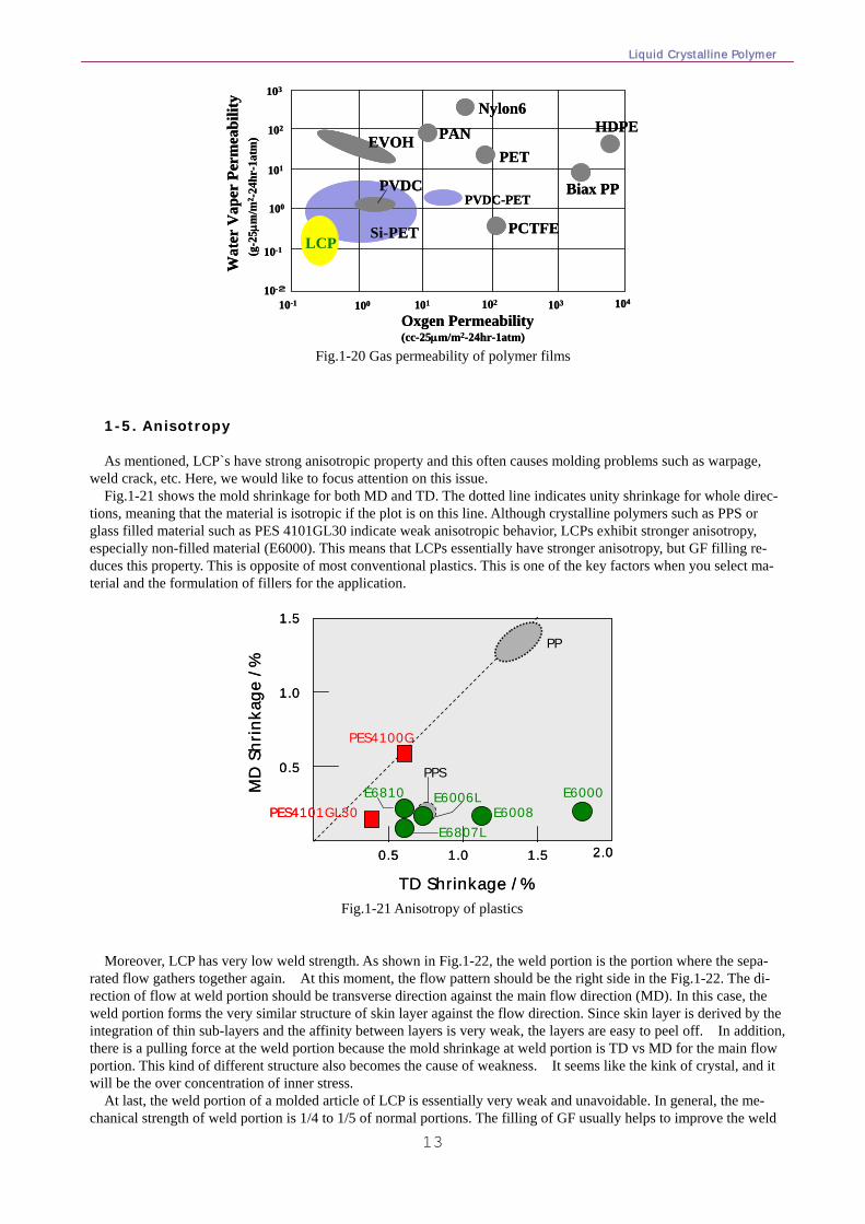
very high density and is strongly integrated by molecules. Accordingly the low molecular structures like gaseous or-ganic chemicals or ions cannot easily permeate through crystalline portion. It is the same for LCP, because the skin layer of LCP is the highly crystallized portion of LCP molecule. For this reason, LCP`s exhibit excellent gas barrier properties. Fig.1-20 shows gas permeability data for many kinds of polymer films. It reveals that water and oxygen permeability of LCP is superior to any other plastic film and it is close to that of Aluminum Foil.
Liquid Crystalline Polymer
13
Nylon6HDPE
Biax PP
PCTFE
PET
PVDC-PET
PAN
PVDC
Si-PET
EVOH
LCP
Oxgen Permeability(cc-25μm/m2-24hr-1atm)
Wat
erV
aper
Perm
eabi
lity
(g-2
5μm
/m2 -
24hr
-1at
m)
10-1 100 101 102 103 104
10-1
101
102
103
10-2
100
Nylon6HDPE
Biax PP
PCTFE
PET
PVDC-PET
PAN
PVDC
Si-PET
EVOH
LCP
Oxgen Permeability(cc-25μm/m2-24hr-1atm)
Wat
erV
aper
Perm
eabi
lity
(g-2
5μm
/m2 -
24hr
-1at
m)
10-1 100 101 102 103 104
10-1
101
102
103
10-2
100
Fig.1-20 Gas permeability of polymer films
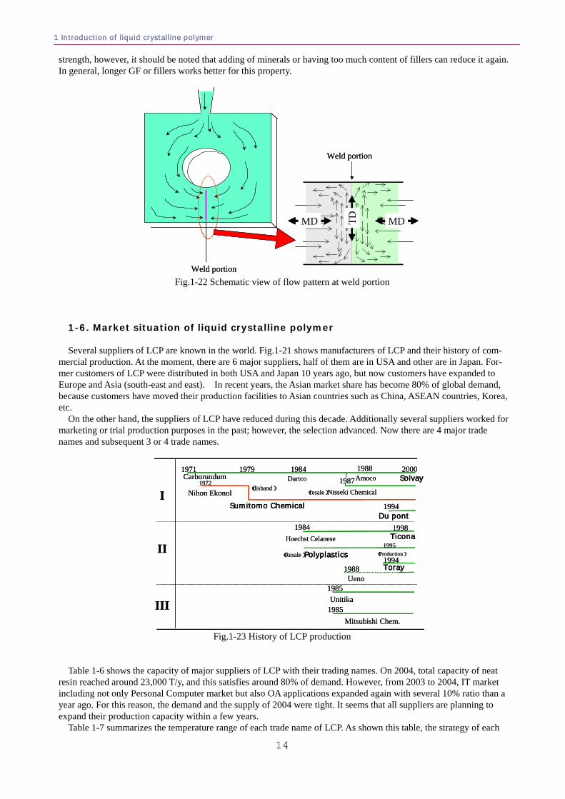
1-5. Anisotropy As mentioned, LCP`s have strong anisotropic property and this often causes molding problems such as warpage,
weld crack, etc. Here, we would like to focus attention on this issue. Fig.1-21 shows the mold shrinkage for both MD and TD. The dotted line indicates unity shrinkage for whole direc-
tions, meaning that the material is isotropic if the plot is on this line. Although crystalline polymers such as PPS or glass filled material such as PES 4101GL30 indicate weak anisotropic behavior, LCPs exhibit stronger anisotropy, especially non-filled material (E6000). This means that LCPs essentially have stronger anisotropy, but GF filling re-duces this property. This is opposite of most conventional plastics. This is one of the key factors when you select ma-terial and the formulation of fillers for the application.
0.5 1.0 1.5 2.0
0.5
1.0
E6000E6006LE6008
E6810
E6807L
PES4100G
PES4101GL30
TD Shrinkage /%
MD
Shr
inka
ge /
%
1.5
PPS
PP
0.5 1.0 1.5 2.0
0.5
1.0
E6000E6006LE6008
E6810
E6807L
PES4100G
PES4101GL30
TD Shrinkage /%
MD
Shr
inka
ge /
%
1.5
PPS
PP
Fig.1-21 Anisotropy of plastics
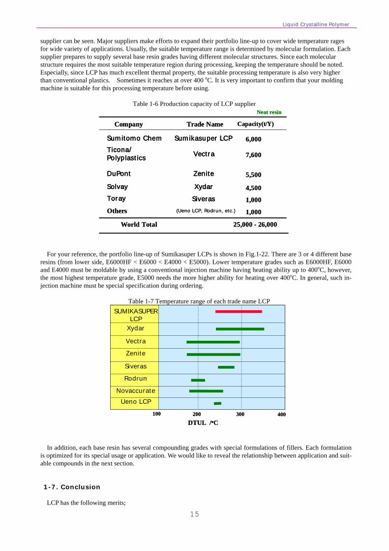
Moreover, LCP has very low weld strength. As shown in Fig.1-22, the weld portion is the portion where the sepa-rated flow gathers together again. At this moment, the flow pattern should be the right side in the Fig.1-22. The di-rection of flow at weld portion should be transverse direction against the main flow direction (MD). In this case, the weld portion forms the very similar structure of skin layer against the flow direction. Since skin layer is derived by the integration of thin sub-layers and the affinity between layers is very weak, the layers are easy to peel off. In addition, there is a pulling force at the weld portion because the mold shrinkage at weld portion is TD vs MD for the main flow portion. This kind of different structure also becomes the cause of weakness. It seems like the kink of crystal, and it will be the over concentration of inner stress.
At last, the weld portion of a molded article of LCP is essentially very weak and unavoidable. In general, the me-chanical strength of weld portion is 1/4 to 1/5 of normal portions. The filling of GF usually helps to improve the weld
1 Introduction of liquid crystalline polymer
14
strength, however, it should be noted that adding of minerals or having too much content of fillers can reduce it again. In general, longer GF or fillers works better for this property.
Weld portion
Weld portion
MDTDMD
Weld portion
Weld portion
MDMDTDMDMD
Fig.1-22 Schematic view of flow pattern at weld portion
1-6. Market situation of liquid crystalline polymer Several suppliers of LCP are known in the world. Fig.1-21 shows manufacturers of LCP and their history of com-
mercial production. At the moment, there are 6 major suppliers, half of them are in USA and other are in Japan. For-mer customers of LCP were distributed in both USA and Japan 10 years ago, but now customers have expanded to Europe and Asia (south-east and east). In recent years, the Asian market share has become 80% of global demand, because customers have moved their production facilities to Asian countries such as China, ASEAN countries, Korea, etc.
On the other hand, the suppliers of LCP have reduced during this decade. Additionally several suppliers worked for marketing or trial production purposes in the past; however, the selection advanced. Now there are 4 major trade names and subsequent 3 or 4 trade names.
Toray
I
1971 1984 1988Amoco
(resale)Nisseki Chemical
Du pont1994
Dartco 1987Carborundum1972
Nihon Ekonol(disband)
1979
Sumitomo Chemical
1984
(Resale)Polyplastics1994
1988Ueno
1985Unitika
1985Mitsubishi Chem.
1998Ticona
1995Hoechst Celanese
(Production)II
III
Solvay2000
Toray
I
1971 1984 1988Amoco
(resale)Nisseki Chemical
Du pont1994
Dartco 1987Carborundum1972
Nihon Ekonol(disband)
1979
Sumitomo Chemical
1984
(Resale)Polyplastics1994
1988Ueno
1985Unitika
1985Mitsubishi Chem.
1998Ticona
1995Hoechst Celanese
(Production)II
III
Solvay2000
Fig.1-23 History of LCP production
Table 1-6 shows the capacity of major suppliers of LCP with their trading names. On 2004, total capacity of neat
resin reached around 23,000 T/y, and this satisfies around 80% of demand. However, from 2003 to 2004, IT market including not only Personal Computer market but also OA applications expanded again with several 10% ratio than a year ago. For this reason, the demand and the supply of 2004 were tight. It seems that all suppliers are planning to expand their production capacity within a few years.
Table 1-7 summarizes the temperature range of each trade name of LCP. As shown this table, the strategy of each
Liquid Crystalline Polymer
15
supplier can be seen. Major suppliers make efforts to expand their portfolio line-up to cover wide temperature rages for wide variety of applications. Usually, the suitable temperature range is determined by molecular formulation. Each supplier prepares to supply several base resin grades having different molecular structures. Since each molecular structure requires the most suitable temperature region during processing, keeping the temperature should be noted. Especially, since LCP has much excellent thermal property, the suitable processing temperature is also very higher than conventional plastics. Sometimes it reaches at over 400 oC. It is very important to confirm that your molding machine is suitable for this processing temperature before using.
Table 1-6 Production capacity of LCP supplier
Company Trade Name Capacity(t/Y)
Ticona/Polyplastics
DuPont
SolvayToray
Vectra
Zenite
XydarSiveras
7,600
5,500
4,500
6,000
1,000
1,000
World Total 25,000 - 26,000
Others
Neat resin
Sumitomo Chem Sumikasuper LCP
(Ueno LCP, Rodrun, etc.)
Company Trade Name Capacity(t/Y)
Ticona/Polyplastics
DuPont
SolvayToray
Vectra
Zenite
XydarSiveras
7,600
5,500
4,500
6,000
1,000
1,000
World Total 25,000 - 26,000
Others
Neat resin
Sumitomo Chem Sumikasuper LCP
(Ueno LCP, Rodrun, etc.)
For your reference, the portfolio line-up of Sumikasuper LCPs is shown in Fig.1-22. There are 3 or 4 different base
resins (from lower side, E6000HF < E6000 < E4000 < E5000). Lower temperature grades such as E6000HF, E6000 and E4000 must be moldable by using a conventional injection machine having heating ability up to 400oC, however, the most highest temperature grade, E5000 needs the more higher ability for heating over 400oC. In general, such in-jection machine must be special specification during ordering.
Table 1-7 Temperature range of each trade name LCP
100 200 300 400DTUL /oC
SUMIKASUPER LCP
Xydar
Vectra
Zenite
Siveras
Rodrun
NovaccurateUeno LCP
100 200 300 400DTUL /oC
SUMIKASUPER LCP
Xydar
Vectra
Zenite
Siveras
Rodrun
NovaccurateUeno LCP
In addition, each base resin has several compounding grades with special formulations of fillers. Each formulation
is optimized for its special usage or application. We would like to reveal the relationship between application and suit-able compounds in the next section.
1-7. Conclusion LCP has the following merits;
1 Introduction of liquid crystalline polymer
16
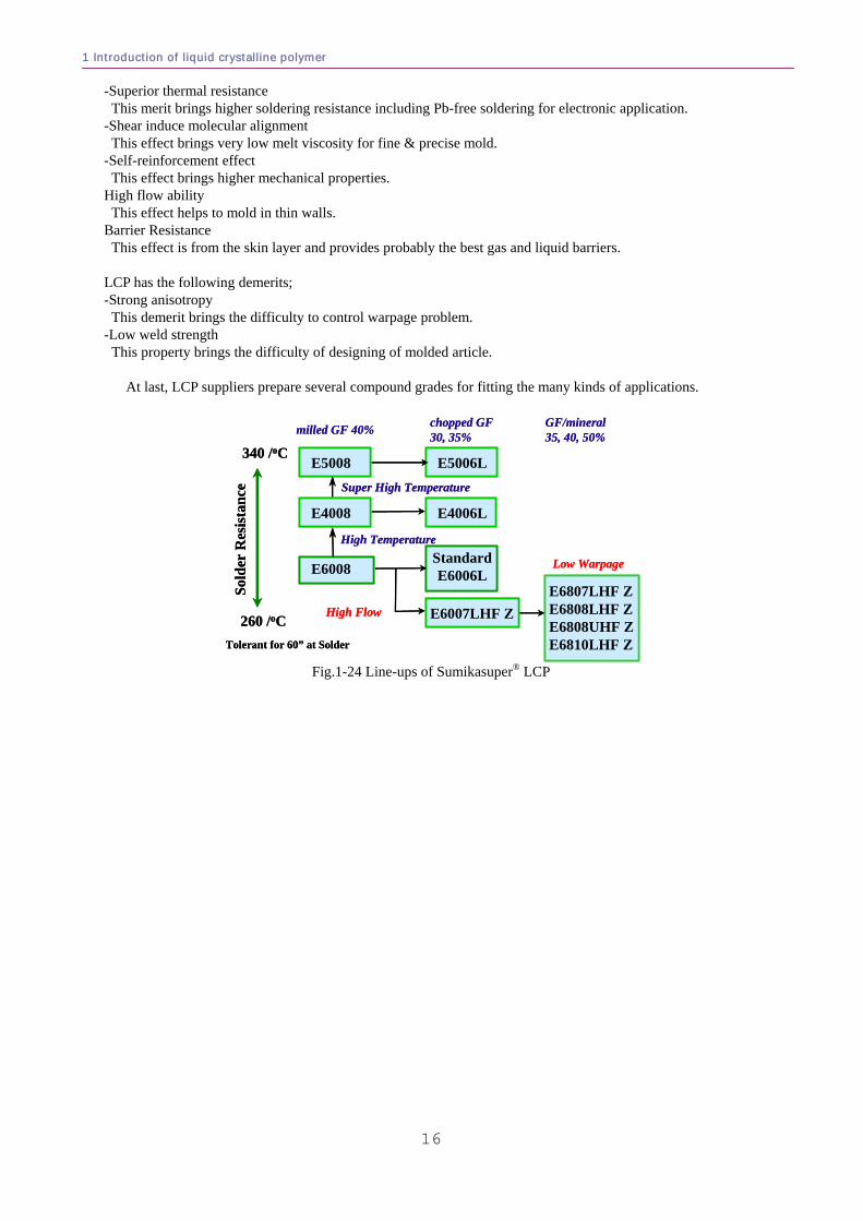
-Superior thermal resistance This merit brings higher soldering resistance including Pb-free soldering for electronic application. -Shear induce molecular alignment This effect brings very low melt viscosity for fine & precise mold. -Self-reinforcement effect This effect brings higher mechanical properties. High flow ability This effect helps to mold in thin walls. Barrier Resistance This effect is from the skin layer and provides probably the best gas and liquid barriers. LCP has the following demerits; -Strong anisotropy This demerit brings the difficulty to control warpage problem. -Low weld strength
This property brings the difficulty of designing of molded article.
At last, LCP suppliers prepare several compound grades for fitting the many kinds of applications.
E6807LHF ZE6808LHF ZE6808UHF ZE6810LHF Z
E6008
E4008
E5008 E5006L
E4006L
StandardE6006L
Super High Temperature
High Temperature
milled GF 40%
340 /oC
260 /oC
Sold
er R
esis
tanc
e
E6007LHF Z
Tolerant for 60” at Solder
Low Warpage
High Flow
chopped GF 30, 35%
GF/mineral35, 40, 50%
E6807LHF ZE6808LHF ZE6808UHF ZE6810LHF Z
E6008
E4008
E5008 E5006L
E4006L
StandardE6006L
Super High Temperature
High Temperature
milled GF 40%
340 /oC
260 /oC
Sold
er R
esis
tanc
e
E6007LHF Z
Tolerant for 60” at Solder
Low Warpage
High Flow
chopped GF 30, 35%
GF/mineral35, 40, 50%
Fig.1-24 Line-ups of Sumikasuper® LCP
Liquid Crystalline Polymer
17
Several applications of LCP have been established. The purpose of this section is to introduce the latest technology
related to each application, which is necessary to understand for the best material selection. The following descrip-tions will disclose tips for choosing the optimized material. 2-1. Connector for PC, mobile, digital camera, etc.19
This application field is one of the largest and the most important for LCP. Over 60% of LCP materials are used
for this market. The total amount of this application of LCP in 2003 is estimated to be approximately 8000MT/yr. Before introducing the grades for this application, we will begin by considering the Surface Mount Technology
(SMT). (1) Surface Mount Technology (SMT) This technology comes from the integration of electronic devices. This is needed due to the limited area or vol-
ume available when minimizing electronic equipment. It is said that Japanese company, SONY has developed this technology to realize the mobile gear, “Walkman”.
For integration of electronic circuits, all devices must be mounted and soldered on the same side of the printed cir-cuit board. This realizes at least 2 times integration of device mounting, because both side of printed circuit board can be used instead of one side use for conventional soldering technology.
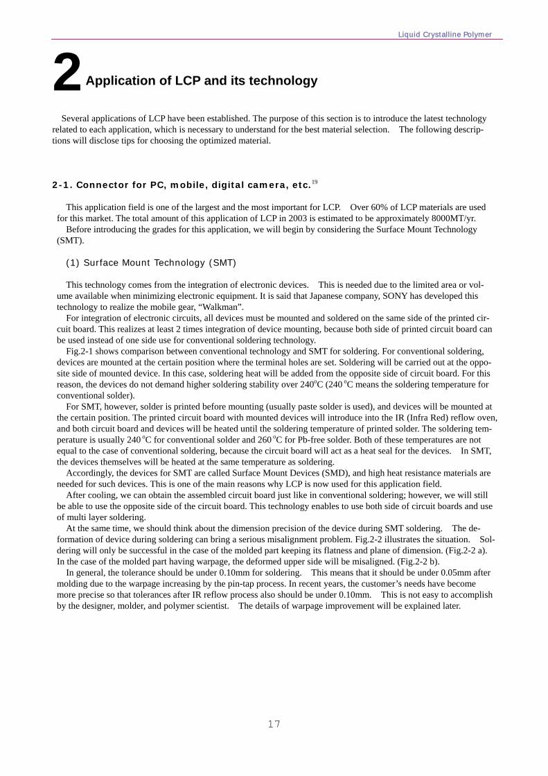
Fig.2-1 shows comparison between conventional technology and SMT for soldering. For conventional soldering, devices are mounted at the certain position where the terminal holes are set. Soldering will be carried out at the oppo-site side of mounted device. In this case, soldering heat will be added from the opposite side of circuit board. For this reason, the devices do not demand higher soldering stability over 240oC (240 oC means the soldering temperature for conventional solder).
For SMT, however, solder is printed before mounting (usually paste solder is used), and devices will be mounted at the certain position. The printed circuit board with mounted devices will introduce into the IR (Infra Red) reflow oven, and both circuit board and devices will be heated until the soldering temperature of printed solder. The soldering tem-perature is usually 240 oC for conventional solder and 260 oC for Pb-free solder. Both of these temperatures are not equal to the case of conventional soldering, because the circuit board will act as a heat seal for the devices. In SMT, the devices themselves will be heated at the same temperature as soldering.
Accordingly, the devices for SMT are called Surface Mount Devices (SMD), and high heat resistance materials are needed for such devices. This is one of the main reasons why LCP is now used for this application field.
After cooling, we can obtain the assembled circuit board just like in conventional soldering; however, we will still be able to use the opposite side of the circuit board. This technology enables to use both side of circuit boards and use of multi layer soldering.
At the same time, we should think about the dimension precision of the device during SMT soldering. The de-formation of device during soldering can bring a serious misalignment problem. Fig.2-2 illustrates the situation. Sol-dering will only be successful in the case of the molded part keeping its flatness and plane of dimension. (Fig.2-2 a). In the case of the molded part having warpage, the deformed upper side will be misaligned. (Fig.2-2 b).
In general, the tolerance should be under 0.10mm for soldering. This means that it should be under 0.05mm after molding due to the warpage increasing by the pin-tap process. In recent years, the customer’s needs have become more precise so that tolerances after IR reflow process also should be under 0.10mm. This is not easy to accomplish by the designer, molder, and polymer scientist. The details of warpage improvement will be explained later.
2 Application of LCP and its technology
2 Application of LCP and its technology
18
printed circuit board electronic part
metal terminal printed circuit (Cu)
soldering bathsoldered
A. Conventional soldering procedure
B. Surface Mount Technological (SMT) soldering procedure
electronic part
metal terminal
printed circuit (Cu)printed solder
~240 oC
IR reflow oven
~240 oC for conventional solder~260 oC for Pb-free solder
soldered
enabling of multi layer soldering
Fig.2-1 Schematic view of comparison between conventional and SMT soldering
PCBTerminal
Solder
a) flat & planery b) with warpage
connector
mis-soldering(not acceptable)
connector
PCBPCBTerminal
Solder
a) flat & planery b) with warpage
connector
mis-soldering(not acceptable)
connector
PCB
Fig.2-2 Relationship between warpage and soldering
(2) Relationship between compound formulation and warpage In general, the higher filler content indicates lower anisotropic property, which is the most important character for
reduction of warpage. However, the relationship differs between filler content and anisotropy among different hy-per-dimensional structures of plastics.
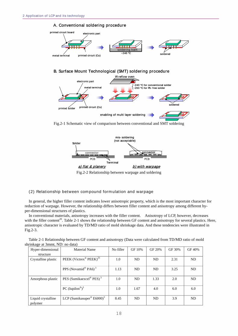
In conventional materials, anisotropy increases with the filler content. Anisotropy of LCP, however, decreases with the filler content20. Table 2-1 shows the relationship between GF content and anisotropy for several plastics. Here, anisotropic character is evaluated by TD/MD ratio of mold shrinkage data. And these tendencies were illustrated in Fig.2-3.
Table 2-1 Relationship between GF content and anisotropy (Data were calculated from TD/MD ratio of mold
shrinkage at 3mmt, ND: no data) Hyper-dimensional
structure Material Name No filler GF 10% GF 20% GF 30% GF 40%
PEEK (Victrex® PEEK)21 1.0 ND ND 2.31 ND Crystalline plastic
PPS (Novamid® PA6) 3 1.13 ND ND 3.25 ND
PES (Sumikaexcel® PES) 3 1.0 ND 1.33 2.0 ND Amorphous plastic
PC (Iupilon®)3 1.0 1.67 4.0 6.0 6.0
Liquid crystalline polymer
LCP (Sumikasuper® E6000)3 8.45 ND ND 3.9 ND
Liquid Crystalline Polymer
19
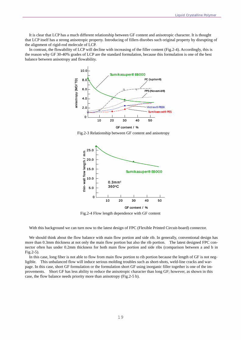
It is clear that LCP has a much different relationship between GF content and anisotropic character. It is thought
that LCP itself has a strong anisotropic property. Introducing of fillers disrobes such original property by disrupting of the alignment of rigid-rod molecule of LCP.
In contrast, the flowability of LCP will decline with increasing of the filler content (Fig.2-4). Accordingly, this is the reason why GF 30-40% grades of LCP are the standard formulation, because this formulation is one of the best balance between anisotropy and flowability.
GF content / %
anis
otro
py (M
D/T
D)
0
2.0
4.0
6.0
8.0
10.0
10 20 30 40 50
Sumikasuper® E6000PC (Iupilon®)
PPS (Novamid®)
Victrex® PEEKSumikaexcel® PES
GF content / %
anis
otro
py (M
D/T
D)
0
2.0
4.0
6.0
8.0
10.0
10 20 30 40 50
Sumikasuper® E6000PC (Iupilon®)
PPS (Novamid®)
Victrex® PEEKSumikaexcel® PES
Fig.2-3 Relationship between GF content and anisotropy
GF content / %
thin
-wal
l flo
w le
ngth
/ m
m
0
5.0
10.0
15.0
20.0
25.0
10 20 30 40 50
Sumikasuper® E6000
0.3mmt
360oC
GF content / %
thin
-wal
l flo
w le
ngth
/ m
m
0
5.0
10.0
15.0
20.0
25.0
10 20 30 40 50
Sumikasuper® E6000
0.3mmt
360oC
Fig.2-4 Flow length dependence with GF content
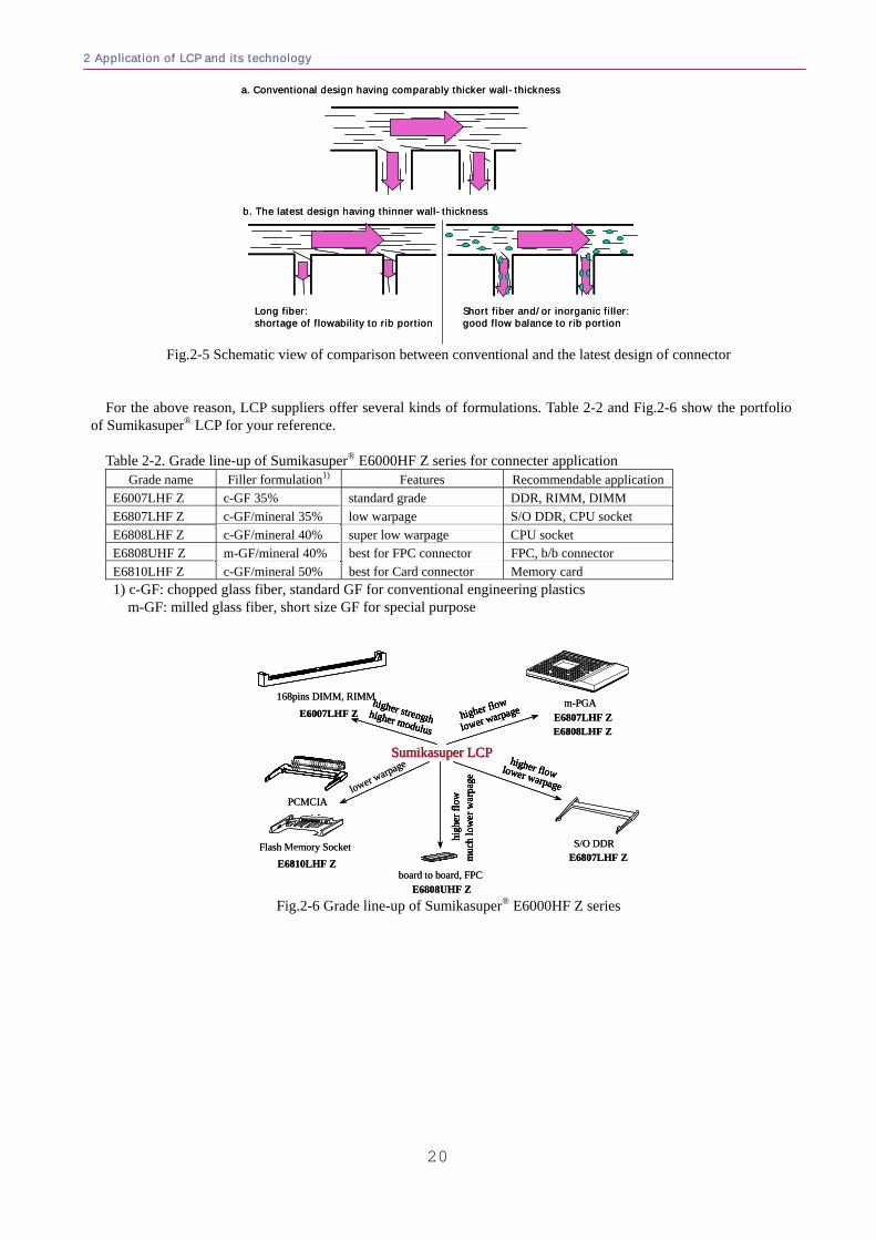
With this background we can turn now to the latest design of FPC (Flexible Printed Circuit-board) connector. We should think about the flow balance with main flow portion and side rib. In generally, conventional design has
more than 0.3mm thickness at not only the main flow portion but also the rib portion. The latest designed FPC con-nector often has under 0.2mm thickness for both main flow portion and side ribs (comparison between a and b in Fig.2-5).
In this case, long fiber is not able to flow from main flow portion to rib portion because the length of GF is not neg-ligible. This unbalanced flow will induce serious molding troubles such as short-shots, weld-line cracks and war-page. In this case, short GF formulation or the formulation short GF using inorganic filler together is one of the im-provements. Short GF has less ability to reduce the anisotropic character than long GF; however, as shown in this case, the flow balance needs priority more than anisotropy (Fig.2-5 b).
2 Application of LCP and its technology
20
a. Conventional design having comparably thicker wall-thickness
b. The latest design having thinner wall-thickness
Long fiber:shortage of flowability to rib portion
Short fiber and/or inorganic filler:good flow balance to rib portion
a. Conventional design having comparably thicker wall-thickness
b. The latest design having thinner wall-thickness
Long fiber:shortage of flowability to rib portion
Short fiber and/or inorganic filler:good flow balance to rib portion
Fig.2-5 Schematic view of comparison between conventional and the latest design of connector
For the above reason, LCP suppliers offer several kinds of formulations. Table 2-2 and Fig.2-6 show the portfolio of Sumikasuper® LCP for your reference.
Table 2-2. Grade line-up of Sumikasuper® E6000HF Z series for connecter application
Grade name Filler formulation1) Features Recommendable application E6007LHF Z c-GF 35% standard grade DDR, RIMM, DIMM E6807LHF Z c-GF/mineral 35% low warpage S/O DDR, CPU socket E6808LHF Z c-GF/mineral 40% super low warpage CPU socket E6808UHF Z m-GF/mineral 40% best for FPC connector FPC, b/b connector E6810LHF Z c-GF/mineral 50% best for Card connector Memory card
1) c-GF: chopped glass fiber, standard GF for conventional engineering plastics m-GF: milled glass fiber, short size GF for special purpose
E6007LHF Z
168pins DIMM, RIMM
E6807LHF ZS/O DDR
Sumikasuper LCPSumikasuper LCP
higher modulus
higher strengthhigher modulus
higher strength higher flow
lower warpagehigher flow
lower warpage
higher flow lower warpage
higher flow lower warpagelower warpage
high
er fl
ow
muc
h lo
wer
war
page
high
er fl
ow
muc
h lo
wer
war
page
board to board, FPCE6810LHF Z
PCMCIA
Flash Memory Socket
m-PGAE6807LHF Z
E6808UHF Z
E6808LHF Z
E6007LHF Z
168pins DIMM, RIMM
E6807LHF ZS/O DDR
Sumikasuper LCPSumikasuper LCPSumikasuper LCPSumikasuper LCP
higher modulus
higher strengthhigher modulus
higher strength higher flow
lower warpagehigher flow
lower warpage
higher flow lower warpage
higher flow lower warpagelower warpage
high
er fl
ow
muc
h lo
wer
war
page
high
er fl
ow
muc
h lo
wer
war
page
board to board, FPCE6810LHF Z
PCMCIA
Flash Memory Socket
m-PGAE6807LHF Z
E6808UHF Z
E6808LHF Z
Fig.2-6 Grade line-up of Sumikasuper® E6000HF Z series
Liquid Crystalline Polymer
21
2-2. Bobbin for backlight inverter of LCD22
From the middle of 2003, the FPD (Flat Panel Display) market has had tremendous growth. LCD (Liquid Crys-talline Display) is one of the most promising items. Lighting in the LCD requires several CCFLs (Cold Cathode Fluorescent Lamp) used according to the panel size. LCP is now being used in the bobbin of the inverter for lighting of CCFL instead of former phenolic resins.
(1) Proceeding of the backlight system of LCD The principle of perceiving of the image on LCD is to view the contrast that is generated by the backlight through a
polarizing panel and liquid crystalline cell. We will omit the detail of technology of the liquid crystalline cell here (please refer the certain literature about this technology). LCD needs light from the outside because it doesn’t emit light itself.
The former LCDs for small calculators or early mobile phones used only natural light. Recent LCDs, however, use active backlights. In general, CCFL (Cold Cathode Fluorescent Lamp) is used for the backlights. CCFL is very similar to the home-use fluorescent lamp; however, it uses the secondary electron emission from electrode made by Ni (nickel) or Ta (tantalum) instead of a filament. The merit of the electrode system is the ability of size reduction. The diameter of a CCFL was 3mmφ several years ago; however, recent diameters are now 1.8mmφ.
The life of LCD depends on the life of CCFL. Since the current CCFL has over 50,000hr life, the LCD life equals over 50,000 hrs.
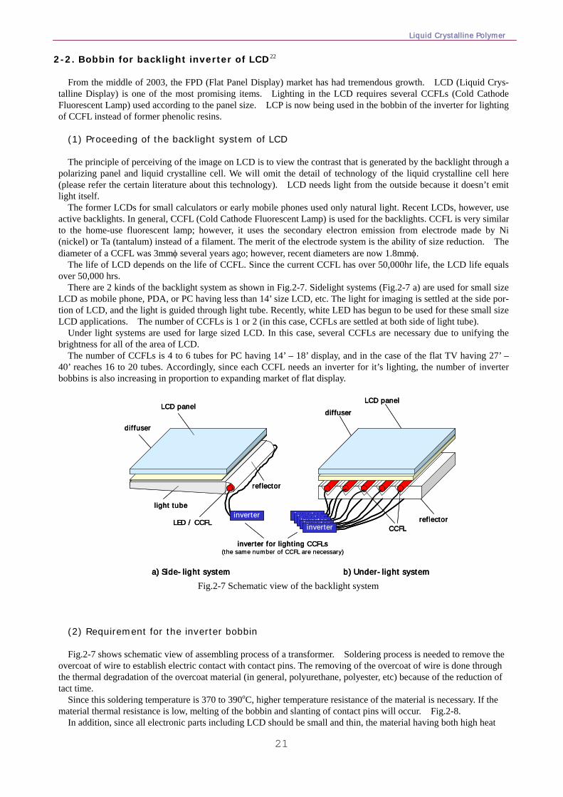
There are 2 kinds of the backlight system as shown in Fig.2-7. Sidelight systems (Fig.2-7 a) are used for small size LCD as mobile phone, PDA, or PC having less than 14’ size LCD, etc. The light for imaging is settled at the side por-tion of LCD, and the light is guided through light tube. Recently, white LED has begun to be used for these small size LCD applications. The number of CCFLs is 1 or 2 (in this case, CCFLs are settled at both side of light tube).
Under light systems are used for large sized LCD. In this case, several CCFLs are necessary due to unifying the brightness for all of the area of LCD.
The number of CCFLs is 4 to 6 tubes for PC having 14’ – 18’ display, and in the case of the flat TV having 27’ – 40’ reaches 16 to 20 tubes. Accordingly, since each CCFL needs an inverter for it’s lighting, the number of inverter bobbins is also increasing in proportion to expanding market of flat display.
inverter
LCD panel
light tube
LED / CCFL
a) Side-light system
diffuser
CCFL
b) Under-light system
diffuser
LCD panel
reflectorinverter
reflector
inverterinverterinverterinverter
inverter for lighting CCFLs(the same number of CCFL are necessary)
inverterinverter
LCD panel
light tube
LED / CCFL
a) Side-light system
diffuser
CCFL
b) Under-light system
diffuser
LCD panel
reflectorinverter
reflector
inverterinverterinverterinverter
inverter for lighting CCFLs(the same number of CCFL are necessary)
Fig.2-7 Schematic view of the backlight system
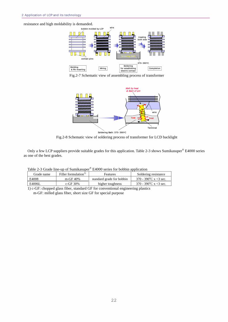
(2) Requirement for the inverter bobbin Fig.2-7 shows schematic view of assembling process of a transformer. Soldering process is needed to remove the
overcoat of wire to establish electric contact with contact pins. The removing of the overcoat of wire is done through the thermal degradation of the overcoat material (in general, polyurethane, polyester, etc) because of the reduction of tact time.
Since this soldering temperature is 370 to 390oC, higher temperature resistance of the material is necessary. If the material thermal resistance is low, melting of the bobbin and slanting of contact pins will occur. Fig.2-8.
In addition, since all electronic parts including LCD should be small and thin, the material having both high heat
2 Application of LCP and its technology
22
resistance and high moldability is demanded.
Molding& Pin Inserting Wiring
Solderingfor establishingelectric contact
370-390oC
Soldering Bathcontact pins
bobbin molded by LCP wire
Completion
treatingboth side
Fig.2-7 Schematic view of assembling process of transformer
Soldering Bath: 370-390oC
Melt by heat& Slant of pin
wire
Terminal
heatheat
Fig.2-8 Schematic view of soldering process of transformer for LCD backlight
Only a few LCP suppliers provide suitable grades for this application. Table 2-3 shows Sumikasuper® E4000 series
as one of the best grades. Table 2-3 Grade line-up of Sumikasuper® E4000 series for bobbin application
Grade name Filler formulation1) Features Soldering resistance E4008 m-GF 40% standard grade for bobbin 370 - 390oC x <3 sec. E4006L c-GF 30% higher toughness 370 - 390oC x <3 sec.
1) c-GF: chopped glass fiber, standard GF for conventional engineering plastics m-GF: milled glass fiber, short size GF for special purpose
Liquid Crystalline Polymer
23
2-3. OPU (Optical Pick-Up) actuator bobbin for CD-ROM, DVD, etc.23 OPU (Optical Pick-Up) is the electronic part that enables the reading and writing of digital data, which is assem-
bled in the CD-R or DVD media drive unit. Recent developments realized high-speed responses through use of LCP in the actuator bobbin for laser focusing.
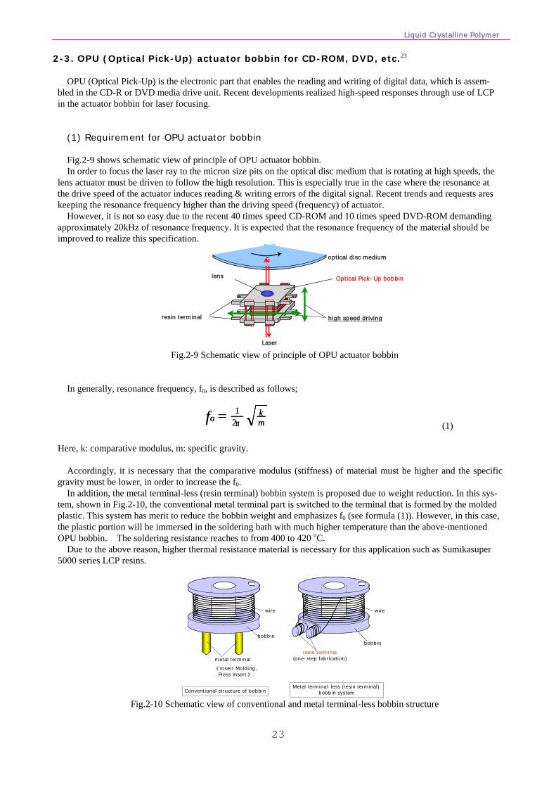
(1) Requirement for OPU actuator bobbin Fig.2-9 shows schematic view of principle of OPU actuator bobbin. In order to focus the laser ray to the micron size pits on the optical disc medium that is rotating at high speeds, the
lens actuator must be driven to follow the high resolution. This is especially true in the case where the resonance at the drive speed of the actuator induces reading & writing errors of the digital signal. Recent trends and requests ares keeping the resonance frequency higher than the driving speed (frequency) of actuator.
However, it is not so easy due to the recent 40 times speed CD-ROM and 10 times speed DVD-ROM demanding approximately 20kHz of resonance frequency. It is expected that the resonance frequency of the material should be improved to realize this specification.
lens Optical Pick-Up bobbin
Laser
resin terminal
optical disc medium
high speed driving
Fig.2-9 Schematic view of principle of OPU actuator bobbin
In generally, resonance frequency, f0, is described as follows;
mkof
π21= m
kofπ21=
(1)
Here, k: comparative modulus, m: specific gravity.
Accordingly, it is necessary that the comparative modulus (stiffness) of material must be higher and the specific gravity must be lower, in order to increase the f0.
In addition, the metal terminal-less (resin terminal) bobbin system is proposed due to weight reduction. In this sys-tem, shown in Fig.2-10, the conventional metal terminal part is switched to the terminal that is formed by the molded plastic. This system has merit to reduce the bobbin weight and emphasizes f0 (see formula (1)). However, in this case, the plastic portion will be immersed in the soldering bath with much higher temperature than the above-mentioned OPU bobbin. The soldering resistance reaches to from 400 to 420 oC.
Due to the above reason, higher thermal resistance material is necessary for this application such as Sumikasuper 5000 series LCP resins.
Metal terminal-less (resin terminal) bobbin system
resin terminal(one-step fabrication)
wire
bobbin
metal terminal (Insert Molding,
Press Insert)
bobbin
wire
Conventional structure of bobbin Fig.2-10 Schematic view of conventional and metal terminal-less bobbin structure
2 Application of LCP and its technology
24
(2) Relationship between modulus and thermal resistance As with conventional plastics, higher filler content of LCP will bring higher stiffness. However it will also bring the
increase of specific gravity at the same time. Accordingly, the balance between filler content, higher stiffness, and lower specific gravity should be considered.
In addition, since LCP has the characteristic that thinner wall thickness will bring higher modulus, the thinner ac-tuator will have merit of the improved design for higher resonance frequency (see section 1-4, Fig.1-15).
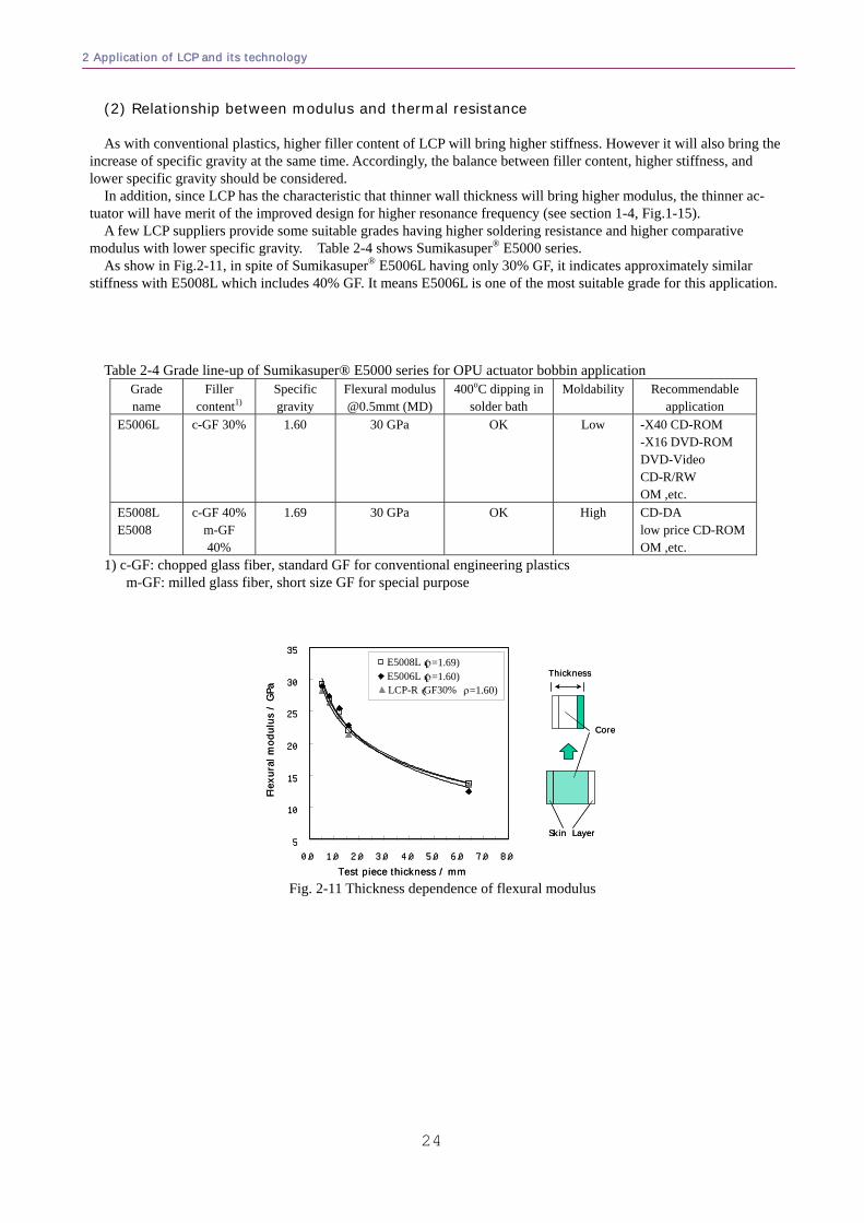
A few LCP suppliers provide some suitable grades having higher soldering resistance and higher comparative modulus with lower specific gravity. Table 2-4 shows Sumikasuper® E5000 series.
As show in Fig.2-11, in spite of Sumikasuper® E5006L having only 30% GF, it indicates approximately similar stiffness with E5008L which includes 40% GF. It means E5006L is one of the most suitable grade for this application.
Table 2-4 Grade line-up of Sumikasuper® E5000 series for OPU actuator bobbin application
Grade name
Filler content1)
Specific gravity
Flexural [email protected] (MD)
400oC dipping insolder bath
Moldability Recommendable application
E5006L c-GF 30% 1.60 30 GPa OK Low -X40 CD-ROM -X16 DVD-ROM DVD-Video CD-R/RW OM ,etc.
E5008L E5008
c-GF 40% m-GF 40%
1.69 30 GPa OK High CD-DA low price CD-ROMOM ,etc.
1) c-GF: chopped glass fiber, standard GF for conventional engineering plastics m-GF: milled glass fiber, short size GF for special purpose
Core
Skin Layer
Thickness
5
10
15
20
25
30
35
0.0 1.0 2.0 3.0 4.0 5.0 6.0 7.0 8.0
Test piece thickness / mm
Flex
ural
mod
ulus
/GP
a
E5008L(ρ=1.69)E5006L(ρ=1.60)LCP-R(GF30% ρ=1.60)
Core
Skin Layer
Thickness
5
10
15
20
25
30
35
0.0 1.0 2.0 3.0 4.0 5.0 6.0 7.0 8.0
Test piece thickness / mm
Flex
ural
mod
ulus
/GP
a
E5008L(ρ=1.69)E5006L(ρ=1.60)LCP-R(GF30% ρ=1.60)
Fig. 2-11 Thickness dependence of flexural modulus
Liquid Crystalline Polymer
25
In recent years, there is strong demand for materials that can be used for lighter, smaller, and thinner products.
However, thin-wall portions less than 0.2mm are difficult to mold even if improved LCP grades are used. In these cases, the thin-wall fluidity depends on the characteristic of injection molding machines. The purpose of this section is to investigate the relationship between thin-wall fluidity of LCP and the characteristic of injection molding ma-chines.
3-1. Control System of Injection Process
Before investigating the relationship of injection machine, we will begin by summarizing the principle of the con-trol system of injection machine.
The condition of the injection process can greatly affect the quality of molding products. There are two control sys-tems -"open loop control" and "closed loop control".
(1) Open loop control
Computerized Numerical Controller
Setting value
-velocity
-pressure
-screw position
etc.
screw position
pressure
Injection unit
Computerized Numerical Controller
Setting value
-velocity
-pressure
-screw position
etc.
screw position
pressure
Injection unit
Fig.3-1 Schematic view of open-loop control
Open loop control is a non-feedback control system. Since this system has comparably lower cost and simple
structure, many kinds of injection machines are used for a wide variety of plastic molding. Open loop control, however, realizes lower reliability for the velocity (injection speed) due to it not feeding the ac-
tual velocity and pressure to the controlling unit. Injection speed is usually affected by the flow resistance induced by the material viscosity and tool cavity design (ex. gate, narrow portions of cavities, etc). Other factors such as the oil temperature and the viscosity of the molding material could also influence the real condition of the injection, and thus they might be often different from the set value.
Important setting parameters are as follows: Pressure setting: this means both injection pressure and holding pressure Velocity setting: “hydraulic flow” for hydraulic system vs. velocity.
Usually, this kind of machine uses lower response parts such as switching valves for hydraulic systems. It some-times causes the generation of excess shock pressure.
3 Injection molding technology for LCP
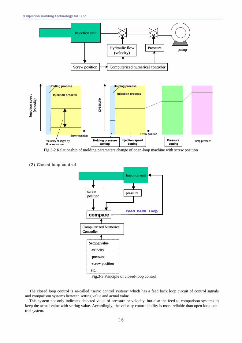
3 Injection molding technology for LCP
26
Injection unit
Pressure
Screw position
Hydraulic flow(velocity)
Computerized numerical controler
pump
Pump pressurePressure Pressure settingsetting
Screw position
Injection process
Holding process
pres
sure
Injection speed Injection speed settingsetting
Holding pressureHolding pressuresettingsetting
Screw position
Injection process
Holding process
Inje
ctio
n sp
eed
(vel
ocity
)
Velocity changes by flow resistance
Fig.3-2 Relationship of molding parameters change of open-loop machine with screw position
(2) Closed loop control
Setting value
-velocity
-pressure
-screw position
etc.
screw position
pressure
Injection unit
Feed back loopFeed back loopcomparecompare
Computerized Numerical Controller
Setting value
-velocity
-pressure
-screw position
etc.
screw position
pressure
Injection unit
Feed back loopFeed back loopcomparecompare
Computerized Numerical Controller
Fig.3-3 Principle of closed-loop control
The closed loop control is so-called “servo control system” which has a feed back loop circuit of control signals and comparison systems between setting value and actual value.
This system not only indicates detected value of pressure or velocity, but also the feed to comparison systems to keep the actual value with setting value. Accordingly, the velocity controllability is more reliable than open loop con-trol system.
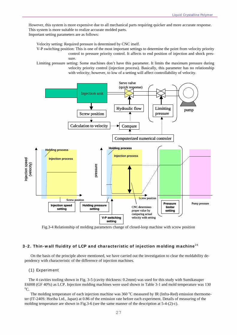
Liquid Crystalline Polymer
27
However, this system is more expensive due to all mechanical parts requiring quicker and more accurate response. This system is more suitable to realize accurate molded parts. Important setting parameters are as follows: Velocity setting: Required pressure is determined by CNC itself. V-P switching position: This is one of the most important settings to determine the point from velocity priority
control to pressure priority control. It affects to end position of injection and shock pres-sure.
Limiting pressure setting: Some machines don’t have this parameter. It limits the maximum pressure during velocity priority control (injection process). Basically, this parameter has no relationship with velocity; however, to low of a setting will affect controllability of velocity.
Injection unit
LimittingpressureScrew position
Hydraulic flow
Computerized numerical controler
Calculation to velocity Compare
pump
Servo valve(quick response)
Pump pressurePressure Pressure limiterlimitersettingsetting
Injection process
Holding process
Holding pressureHolding pressuresettingsetting CNC determines
proper value by comparing actual velocity with settingVV--P switchingP switching
settingsetting
Screw positionScrew position
Injection process
Holding process
Inje
ctio
n sp
eed
(vel
ocity
)
Injection speed Injection speed settingsetting
pres
sure
Fig.3-4 Relationship of molding parameters change of closed-loop machine with screw position
3-2. Thin-wall fluidity of LCP and characteristic of injection molding machine24
On the basis of the principle above mentioned, we have carried out the investigation to clear the moldability de-
pendency with characteristic of the difference of injection machines. (1) Experiment The 4 cavities tooling shown in Fig. 3-5 (cavity thickness: 0.2mmt) was used for this study with Sumikasuper
E6008 (GF 40%) as LCP. Injection molding machines were used shown in Table 3-1 and mold temperature was 130 oC.
The molding temperature of each injection machine was 360 oC measured by IR (Infra-Red) emission thermome-ter (IT-240S: Horiba Ltd., Japan) at 0.86 of the emission rate before each experiment. Details of measuring of the molding temperature are shown in Fig.3-6 (see the same manner of the description at 5-4-(2)-c).
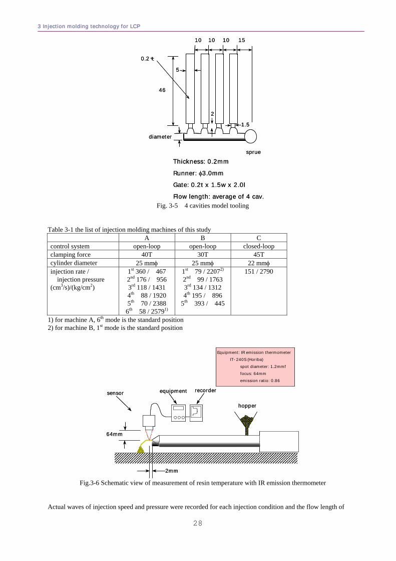
3 Injection molding technology for LCP
28
Thickness: 0.2mm
Runner: φ3.0mm
Gate: 0.2t x 1.5w x 2.0l
Flow length: average of 4 cav.
diameter
10 10 15
sprue
10
46
0.2t
5
1.5
2
Thickness: 0.2mm
Runner: φ3.0mm
Gate: 0.2t x 1.5w x 2.0l
Flow length: average of 4 cav.
diameter
10 10 15
sprue
10
46
0.2t
5
1.5
2
Fig. 3-5 4 cavities model tooling
Table 3-1 the list of injection molding machines of this study A B C control system open-loop open-loop closed-loop clamping force 40T 30T 45T cylinder diameter 25 mmφ 25 mmφ 22 mmφ injection rate /
injection pressure (cm3/s)/(kg/cm2)
1st 360 / 467 2nd 176 / 956 3rd 118 / 1431 4th 88 / 1920 5th 70 / 2388
6th 58 / 25791)
1st 79 / 22072) 2nd 99 / 1763 3rd 134 / 1312 4th 195 / 896
5th 393 / 445
151 / 2790
1) for machine A, 6th mode is the standard position 2) for machine B, 1st mode is the standard position
sensor equipment recorder
hopper
Equipment: IR emission thermometerIT-240S (Horiba)
spot diameter: 1.2mmf focus: 64mm emission ratio: 0.86
64mm
2mm
sensor equipment recorder
hopper
Equipment: IR emission thermometerIT-240S (Horiba)
spot diameter: 1.2mmf focus: 64mm emission ratio: 0.86
64mm
2mm
Fig.3-6 Schematic view of measurement of resin temperature with IR emission thermometer Actual waves of injection speed and pressure were recorded for each injection condition and the flow length of
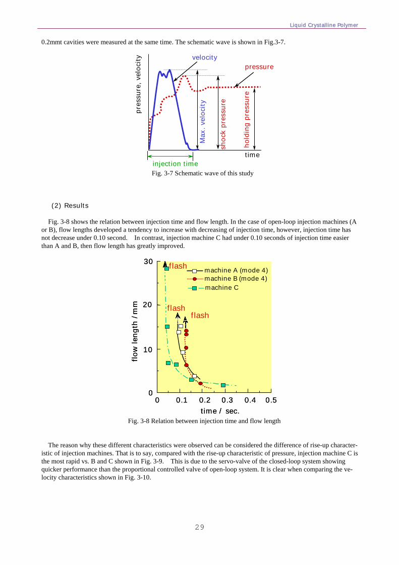
Liquid Crystalline Polymer
29
0.2mmt cavities were measured at the same time. The schematic wave is shown in Fig.3-7.
pres
sure
, vel
ocity
pressure
Max
. vel
ocity
shoc
k pr
essu
re
hold
ing
pres
sure
injection timetime
velocity
Fig. 3-7 Schematic wave of this study
(2) Results Fig. 3-8 shows the relation between injection time and flow length. In the case of open-loop injection machines (A
or B), flow lengths developed a tendency to increase with decreasing of injection time, however, injection time has not decrease under 0.10 second. In contrast, injection machine C had under 0.10 seconds of injection time easier than A and B, then flow length has greatly improved.
flow
leng
th /
mm
time / sec.
0
10
20
30
0 0.1 0.2 0.3 0.4 0.5
flashflash
flash
machine Cmachine B (mode 4)machine A (mode 4)
flow
leng
th /
mm
time / sec.
0
10
20
30
0 0.1 0.2 0.3 0.4 0.5
flashflash
flash
machine Cmachine B (mode 4)machine A (mode 4)
Fig. 3-8 Relation between injection time and flow length
The reason why these different characteristics were observed can be considered the difference of rise-up character-
istic of injection machines. That is to say, compared with the rise-up characteristic of pressure, injection machine C is the most rapid vs. B and C shown in Fig. 3-9. This is due to the servo-valve of the closed-loop system showing quicker performance than the proportional controlled valve of open-loop system. It is clear when comparing the ve-locity characteristics shown in Fig. 3-10.
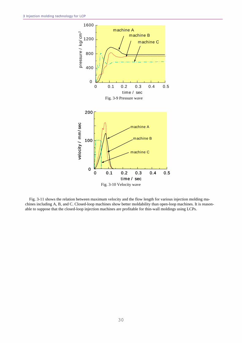
3 Injection molding technology for LCP
30
0 0.1 0.2 0.3 0.4 0.5pr
essu
re /
kg/
cm2
time / sec
0
400
800
1200
1600machine A
machine Bmachine C
Fig. 3-9 Pressure wave
velo
city
/ m
m/s
ec
0
100
200
0 0.1 0.2 0.3 0.4 0.5time / sec
machine A
machine B
machine C
velo
city
/ m
m/s
ec
0
100
200
0 0.1 0.2 0.3 0.4 0.5time / sec
machine A
machine B
machine C
Fig. 3-10 Velocity wave
Fig. 3-11 shows the relation between maximum velocity and the flow length for various injection molding ma-chines including A, B, and C. Closed-loop machines show better moldability than open-loop machines. It is reason-able to suppose that the closed-loop injection machines are profitable for thin-wall moldings using LCPs.
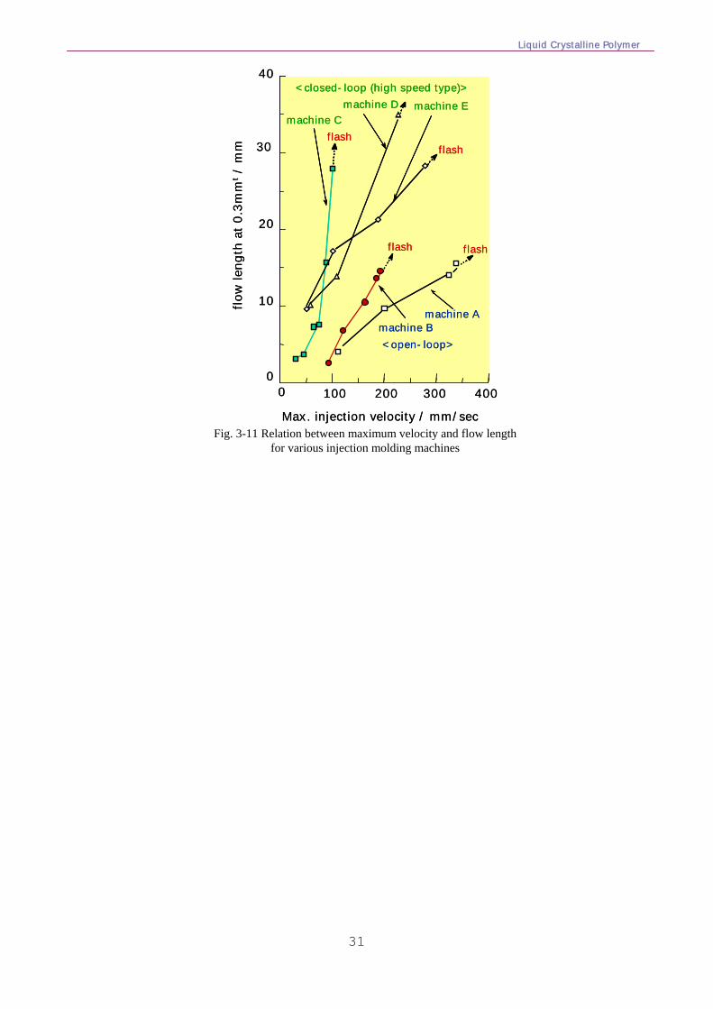
Liquid Crystalline Polymer
31
100 200 300
flow
leng
th a
t 0.3
mm
t/
mm
Max. injection velocity / mm/sec
0
10
20
30
40
0 400
machine Amachine B
machine Cmachine D machine E
<closed-loop (high speed type)>
<open-loop>
flashflash
flash flash
100 200 300
flow
leng
th a
t 0.3
mm
t/
mm
Max. injection velocity / mm/sec
0
10
20
30
40
0 400
machine Amachine B
machine Cmachine D machine E
<closed-loop (high speed type)>
<open-loop>
flashflash
flash flash
machine Amachine B
machine Cmachine D machine E
<closed-loop (high speed type)>
<open-loop>
flashflash
flash flash
Fig. 3-11 Relation between maximum velocity and flow length
for various injection molding machines
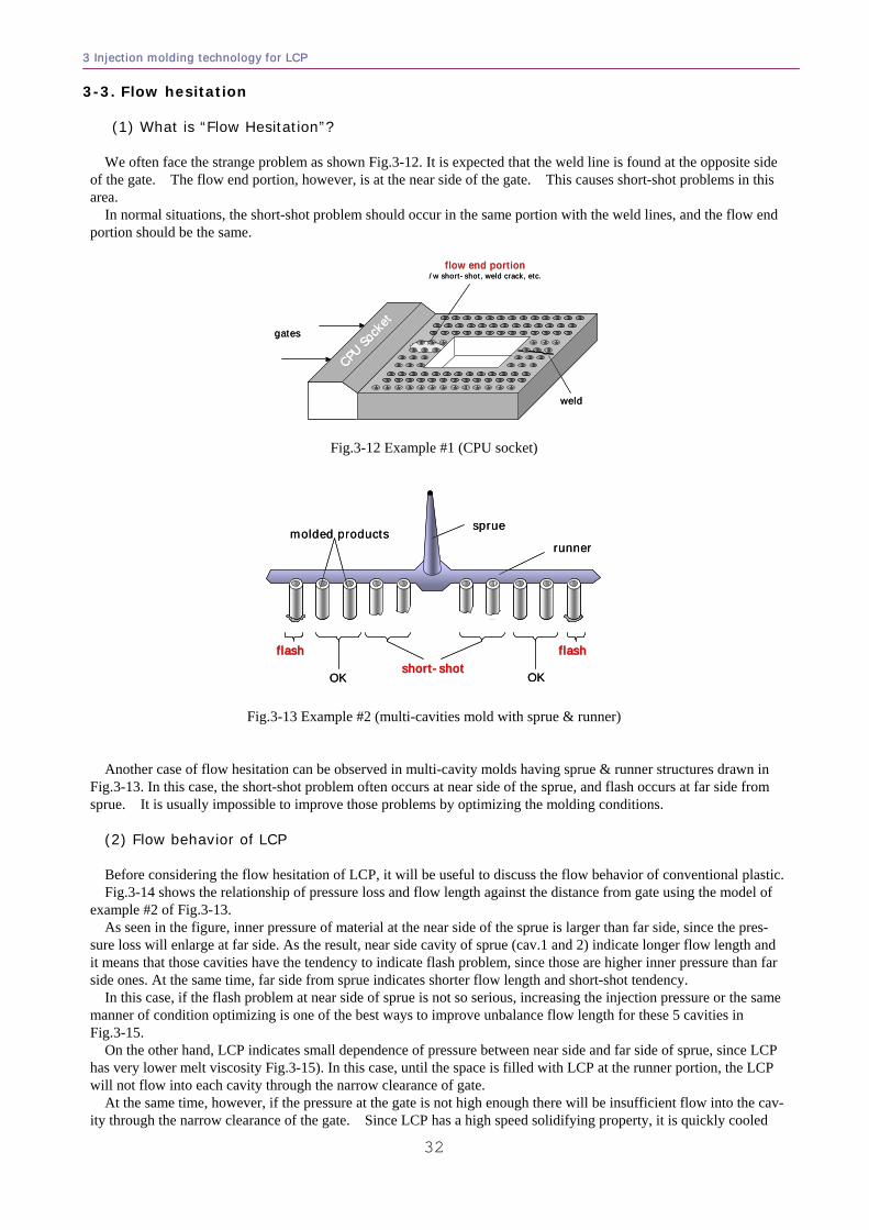
3 Injection molding technology for LCP
32
3-3. Flow hesitation (1) What is “Flow Hesitation”? We often face the strange problem as shown Fig.3-12. It is expected that the weld line is found at the opposite side
of the gate. The flow end portion, however, is at the near side of the gate. This causes short-shot problems in this area.
In normal situations, the short-shot problem should occur in the same portion with the weld lines, and the flow end portion should be the same.
gates
weld
flow end portionflow end portion/w short-shot, weld crack, etc.
CPU So
cket
CPU So
cket
CPU So
cket
gates
weld
flow end portionflow end portion/w short-shot, weld crack, etc.
CPU So
cket
CPU So
cket
CPU So
cket
Fig.3-12 Example #1 (CPU socket)
sprue
runnermolded products
flashflashshortshort--shotshot
OK
flashflash
OK
sprue
runnermolded products
flashflashshortshort--shotshot
OK
flashflash
OK
Fig.3-13 Example #2 (multi-cavities mold with sprue & runner)
Another case of flow hesitation can be observed in multi-cavity molds having sprue & runner structures drawn in Fig.3-13. In this case, the short-shot problem often occurs at near side of the sprue, and flash occurs at far side from sprue. It is usually impossible to improve those problems by optimizing the molding conditions.
(2) Flow behavior of LCP Before considering the flow hesitation of LCP, it will be useful to discuss the flow behavior of conventional plastic. Fig.3-14 shows the relationship of pressure loss and flow length against the distance from gate using the model of
example #2 of Fig.3-13. As seen in the figure, inner pressure of material at the near side of the sprue is larger than far side, since the pres-
sure loss will enlarge at far side. As the result, near side cavity of sprue (cav.1 and 2) indicate longer flow length and it means that those cavities have the tendency to indicate flash problem, since those are higher inner pressure than far side ones. At the same time, far side from sprue indicates shorter flow length and short-shot tendency.
In this case, if the flash problem at near side of sprue is not so serious, increasing the injection pressure or the same manner of condition optimizing is one of the best ways to improve unbalance flow length for these 5 cavities in Fig.3-15.
On the other hand, LCP indicates small dependence of pressure between near side and far side of sprue, since LCP has very lower melt viscosity Fig.3-15). In this case, until the space is filled with LCP at the runner portion, the LCP will not flow into each cavity through the narrow clearance of gate.
At the same time, however, if the pressure at the gate is not high enough there will be insufficient flow into the cav-ity through the narrow clearance of the gate. Since LCP has a high speed solidifying property, it is quickly cooled
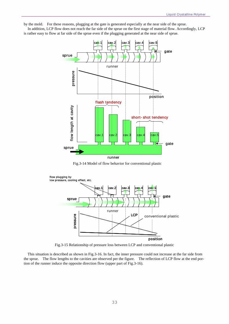
Liquid Crystalline Polymer
33
by the mold. For these reasons, plugging at the gate is generated especially at the near side of the sprue. In addition, LCP flow does not reach the far side of the sprue on the first stage of material flow. Accordingly, LCP
is rather easy to flow at far side of the sprue even if the plugging generated at the near side of sprue.
cav.1 cav.2 cav.3 cav.4 cav.5
pres
sure
position
cav.1 cav.2 cav.3 cav.4 cav.5
flow
leng
th a
t cav
ity
shortshort--shot tendencyshot tendency
flash tendencyflash tendency
sprue
runner
gate
sprue
runner
gate
cav.1 cav.2 cav.3 cav.4 cav.5
pres
sure
position
cav.1 cav.2 cav.3 cav.4 cav.5
flow
leng
th a
t cav
ity
shortshort--shot tendencyshot tendency
flash tendencyflash tendency
sprue
runner
gate
sprue
runner
gate
Fig.3-14 Model of flow behavior for conventional plastic
pres
sure
position
conventional plasticLCP
flow plugging bylow pressure, cooling effect, etc.
runner
cav.1 cav.2 cav.3 cav.4 cav.5
sprue gate
pres
sure
position
conventional plasticLCP
pres
sure
position
conventional plasticLCP
flow plugging bylow pressure, cooling effect, etc.
runner
cav.1 cav.2 cav.3 cav.4 cav.5
sprue gate
cav.1 cav.2 cav.3 cav.4 cav.5
sprue gate
Fig.3-15 Relationship of pressure loss between LCP and conventional plastic
This situation is described as shown in Fig.3-16. In fact, the inner pressure could not increase at the far side from
the sprue. The flow lengths to the cavities are observed per the figure. The reflection of LCP flow at the end por-tion of the runner induce the opposite direction flow (upper part of Fig.3-16).
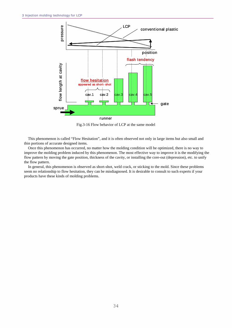
3 Injection molding technology for LCP
34
pres
sure
position
cav.1 cav.2 cav.3 cav.4 cav.5
flow
leng
th a
t cav
ity
flow hesitationflow hesitationappeared as shortappeared as short--shotshot
flash tendencyflash tendency
conventional plasticLCP
sprue
runner
gate
pres
sure
position
cav.1 cav.2 cav.3 cav.4 cav.5
flow
leng
th a
t cav
ity
flow hesitationflow hesitationappeared as shortappeared as short--shotshot
flash tendencyflash tendency
conventional plasticLCP
sprue
runner
gate
Fig.3-16 Flow behavior of LCP at the same model
This phenomenon is called “Flow Hesitation”, and it is often observed not only in large items but also small and
thin portions of accurate designed items. Once this phenomenon has occurred, no matter how the molding condition will be optimized, there is no way to
improve the molding problem induced by this phenomenon. The most effective way to improve it is the modifying the flow pattern by moving the gate position, thickness of the cavity, or installing the core-out (depression), etc. to unify the flow pattern.
In general, this phenomenon is observed as short-shot, weld crack, or sticking to the mold. Since these problems seem no relationship to flow hesitation, they can be misdiagnosed. It is desirable to consult to such experts if your products have these kinds of molding problems.
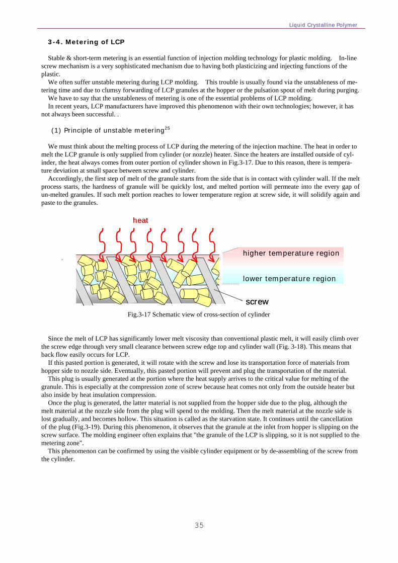
Liquid Crystalline Polymer
35
3-4. Metering of LCP Stable & short-term metering is an essential function of injection molding technology for plastic molding. In-line
screw mechanism is a very sophisticated mechanism due to having both plasticizing and injecting functions of the plastic.
We often suffer unstable metering during LCP molding. This trouble is usually found via the unstableness of me-tering time and due to clumsy forwarding of LCP granules at the hopper or the pulsation spout of melt during purging.
We have to say that the unstableness of metering is one of the essential problems of LCP molding. In recent years, LCP manufacturers have improved this phenomenon with their own technologies; however, it has
not always been successful. . (1) Principle of unstable metering25 We must think about the melting process of LCP during the metering of the injection machine. The heat in order to
melt the LCP granule is only supplied from cylinder (or nozzle) heater. Since the heaters are installed outside of cyl-inder, the heat always comes from outer portion of cylinder shown in Fig.3-17. Due to this reason, there is tempera-ture deviation at small space between screw and cylinder.
Accordingly, the first step of melt of the granule starts from the side that is in contact with cylinder wall. If the melt process starts, the hardness of granule will be quickly lost, and melted portion will permeate into the every gap of un-melted granules. If such melt portion reaches to lower temperature region at screw side, it will solidify again and paste to the granules.
heat
screw
higher temperature region
lower temperature region
heat
screw
higher temperature region
lower temperature region
Fig.3-17 Schematic view of cross-section of cylinder
Since the melt of LCP has significantly lower melt viscosity than conventional plastic melt, it will easily climb over
the screw edge through very small clearance between screw edge top and cylinder wall (Fig. 3-18). This means that back flow easily occurs for LCP.
If this pasted portion is generated, it will rotate with the screw and lose its transportation force of materials from hopper side to nozzle side. Eventually, this pasted portion will prevent and plug the transportation of the material.
This plug is usually generated at the portion where the heat supply arrives to the critical value for melting of the granule. This is especially at the compression zone of screw because heat comes not only from the outside heater but also inside by heat insulation compression.
Once the plug is generated, the latter material is not supplied from the hopper side due to the plug, although the melt material at the nozzle side from the plug will spend to the molding. Then the melt material at the nozzle side is lost gradually, and becomes hollow. This situation is called as the starvation state. It continues until the cancellation of the plug (Fig.3-19). During this phenomenon, it observes that the granule at the inlet from hopper is slipping on the screw surface. The molding engineer often explains that "the granule of the LCP is slipping, so it is not supplied to the metering zone".
This phenomenon can be confirmed by using the visible cylinder equipment or by de-assembling of the screw from the cylinder.
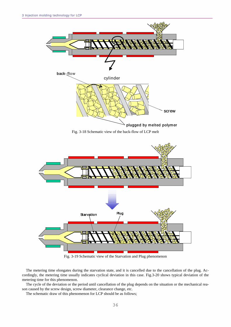
3 Injection molding technology for LCP
36
cylinderback-flow
plugged by melted polymer
screw
cylinderback-flow
plugged by melted polymer
screw
Fig. 3-18 Schematic view of the back-flow of LCP melt
PlugStarvation PlugStarvation PlugStarvation
Fig. 3-19 Schematic view of the Starvation and Plug phenomenon
The metering time elongates during the starvation state, and it is cancelled due to the cancellation of the plug. Ac-cordingly, the metering time usually indicates cyclical deviation in this case. Fig.3-20 shows typical deviation of the metering time for this phenomenon.
The cycle of the deviation or the period until cancellation of the plug depends on the situation or the mechanical rea-son caused by the screw design, screw diameter, clearance change, etc.
The schematic draw of this phenomenon for LCP should be as follows;
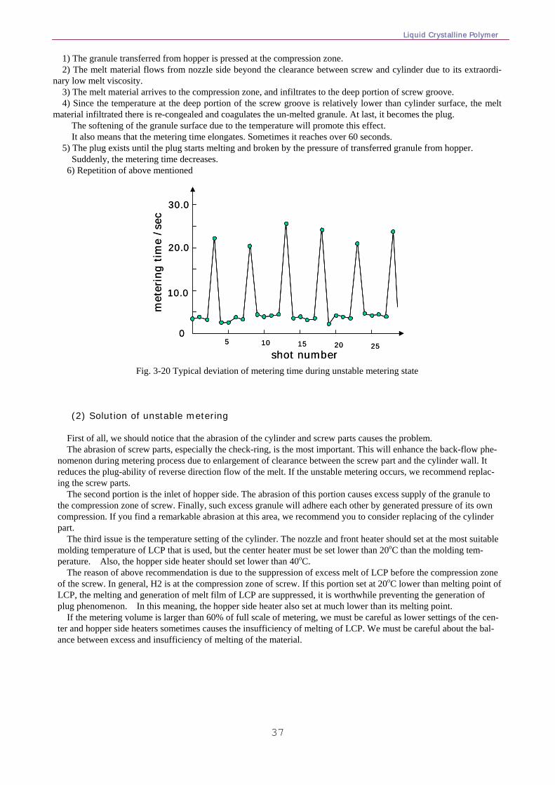
Liquid Crystalline Polymer
37
1) The granule transferred from hopper is pressed at the compression zone. 2) The melt material flows from nozzle side beyond the clearance between screw and cylinder due to its extraordi-
nary low melt viscosity. 3) The melt material arrives to the compression zone, and infiltrates to the deep portion of screw groove. 4) Since the temperature at the deep portion of the screw groove is relatively lower than cylinder surface, the melt
material infiltrated there is re-congealed and coagulates the un-melted granule. At last, it becomes the plug. The softening of the granule surface due to the temperature will promote this effect. It also means that the metering time elongates. Sometimes it reaches over 60 seconds. 5) The plug exists until the plug starts melting and broken by the pressure of transferred granule from hopper. Suddenly, the metering time decreases. 6) Repetition of above mentioned
met
erin
g tim
e /s
ec
shot number
10.0
20.0
30.0
05 10 15 20 25
met
erin
g tim
e /s
ec
shot number
10.0
20.0
30.0
05 10 15 20 25
Fig. 3-20 Typical deviation of metering time during unstable metering state
(2) Solution of unstable metering
First of all, we should notice that the abrasion of the cylinder and screw parts causes the problem. The abrasion of screw parts, especially the check-ring, is the most important. This will enhance the back-flow phe-
nomenon during metering process due to enlargement of clearance between the screw part and the cylinder wall. It reduces the plug-ability of reverse direction flow of the melt. If the unstable metering occurs, we recommend replac-ing the screw parts.
The second portion is the inlet of hopper side. The abrasion of this portion causes excess supply of the granule to the compression zone of screw. Finally, such excess granule will adhere each other by generated pressure of its own compression. If you find a remarkable abrasion at this area, we recommend you to consider replacing of the cylinder part.
The third issue is the temperature setting of the cylinder. The nozzle and front heater should set at the most suitable molding temperature of LCP that is used, but the center heater must be set lower than 20oC than the molding tem-perature. Also, the hopper side heater should set lower than 40oC.
The reason of above recommendation is due to the suppression of excess melt of LCP before the compression zone of the screw. In general, H2 is at the compression zone of screw. If this portion set at 20oC lower than melting point of LCP, the melting and generation of melt film of LCP are suppressed, it is worthwhile preventing the generation of plug phenomenon. In this meaning, the hopper side heater also set at much lower than its melting point.
If the metering volume is larger than 60% of full scale of metering, we must be careful as lower settings of the cen-ter and hopper side heaters sometimes causes the insufficiency of melting of LCP. We must be careful about the bal-ance between excess and insufficiency of melting of the material.
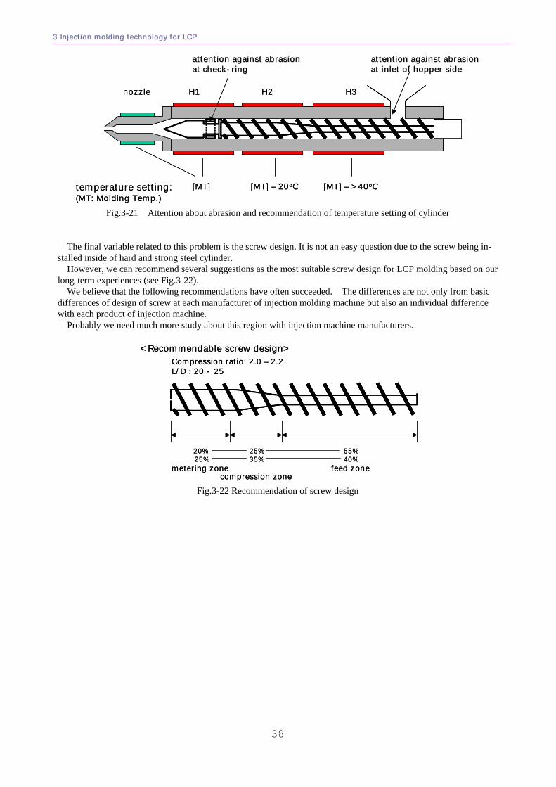
3 Injection molding technology for LCP
38
temperature setting:(MT: Molding Temp.)
[MT] [MT] – 20oC [MT] – >40oC
nozzle H1 H2 H3
attention against abrasionattention against abrasionat inlet of hopper sideat inlet of hopper side
attention against abrasionattention against abrasionat checkat check--ringring
temperature setting:(MT: Molding Temp.)
[MT] [MT] – 20oC [MT] – >40oC
nozzle H1 H2 H3
attention against abrasionattention against abrasionat inlet of hopper sideat inlet of hopper side
attention against abrasionattention against abrasionat checkat check--ringring
Fig.3-21 Attention about abrasion and recommendation of temperature setting of cylinder
The final variable related to this problem is the screw design. It is not an easy question due to the screw being in-stalled inside of hard and strong steel cylinder.
However, we can recommend several suggestions as the most suitable screw design for LCP molding based on our long-term experiences (see Fig.3-22).
We believe that the following recommendations have often succeeded. The differences are not only from basic differences of design of screw at each manufacturer of injection molding machine but also an individual difference with each product of injection machine.
Probably we need much more study about this region with injection machine manufacturers.
20%25%
metering zone
25%35%
compression zone
55%40%
feed zone
<Recommendable screw design>Compression ratio: 2.0 – 2.2L/D : 20 - 25
20%25%
metering zone
25%35%
compression zone
55%40%
feed zone
<Recommendable screw design>Compression ratio: 2.0 – 2.2L/D : 20 - 25
Fig.3-22 Recommendation of screw design
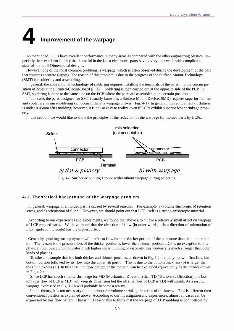
Liquid Crystalline Polymer
39
4 Improvement of the warpage
As mentioned, LCPs have excellent performance in many areas as compared with the other engineering plastics. Es-pecially their excellent fluidity that is useful in the latest electronics parts having very thin-walls with complicated state-of-the-art 3-Dimensional designs. However, one of the most common problems is warpage, which is often observed during the development of the part that requires accurate flatness. The reason of this problem is due to the progress of the Surface-Mount-Technology (SMT) for soldering and assembling.
In general, the conventional technology of soldering requires installing the terminals of the parts into the certain po-sition of holes at the Printed-Circuit-Board (PCB. Soldering is then carried out at the opposite side of the PCB. In SMT, soldering is done at the same side on the PCB where the parts are assembled at the certain position.
In this case, the parts designed for SMT (usually known as a Surface-Mount Device: SMD) requires superior flatness and coplanery as miss-soldering can occur if there is warpage or twist (Fig. 4-1). In general, the requirement of flatness is under 0.05mm after molding; however, it is not so easy to realize even if LCPs exhibit superior low shrinkage prop-erty. In this section, we would like to show the principles of the reduction of the warpage for molded parts by LCPs.
PCB
connector
Terminal
Solder
a) flat & planery b) with warpage
PCB
connector
mis-soldering(not acceptable)
PCB
connector
Terminal
Solder
a) flat & planery b) with warpage
PCB
connector
mis-soldering(not acceptable)
Fig. 4-1 Surface-Mounting Device with/without warpage during soldering
4-1. Theoretical background of the warpage problem In general, warpage of a molded part is caused by several reasons. For example, a) volume shrinkage, b) retention
stress, and c) orientation of filler. However, we should point out that LCP itself is a strong anisotropic material.
According to our experiences and experiments, we found that above a to c have a relatively small affect on warpage of LCP molded parts. We have found that the direction of flow (in other words, it is a direction of orientation of LCP rigid-rod molecule) has the highest affect.
Generally speaking, melt polymers will prefer to flow into the thicker portion of the part more than the thinner por-
tion. The reason is the pressure-loss of the thicker portion is lower than thinner portion. LCP is no exception to this physical rule. Since LCP indicates much higher shear thinning of viscosity, this tendency is much stronger than other kinds of plastics.
To take an example that has both thicker and thinner portions, as drawn in Fig.4-2, the polymer will first flow into bottom portion followed by its flow into the upper rib portion. This is due to the bottom thickness (b) is larger than the rib thickness (a)). In this case, the flow pattern of the material can be explained equivalently as the arrows drawn in Fig.4-2 a.
Since LCP has much smaller shrinkage for MD (Mechanical Direction) than TD (Transverse Direction), the bot-tom (the flow of LCP is MD) will keep its dimension but the rib (the flow of LCP is TD) will shrink. As a result, warpage expressed in Fig. 1-1b will probably become a reality. .
In this theory, it is not necessary to think about the volume shrinkage in terms of thickness. This is different then conventional plastics as explained above. According to our investigation and experiences, almost all cases can be expressed by this flow pattern. That is, it is reasonable to think that the warpage of LCP molding is controllable by
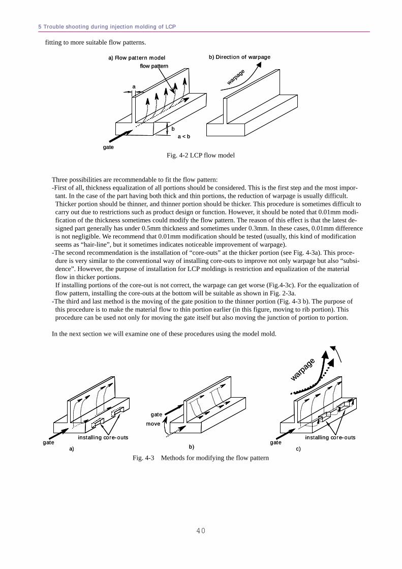
5 Trouble shooting during injection molding of LCP
40
fitting to more suitable flow patterns.
a
ba < b
gate
warpageflow pattern
a) Flow pattern model b) Direction of warpage
a
ba < b
gate
warpageflow pattern
a) Flow pattern model b) Direction of warpage
Fig. 4-2 LCP flow model
Three possibilities are recommendable to fit the flow pattern: -First of all, thickness equalization of all portions should be considered. This is the first step and the most impor-
tant. In the case of the part having both thick and thin portions, the reduction of warpage is usually difficult. Thicker portion should be thinner, and thinner portion should be thicker. This procedure is sometimes difficult to carry out due to restrictions such as product design or function. However, it should be noted that 0.01mm modi-fication of the thickness sometimes could modify the flow pattern. The reason of this effect is that the latest de-signed part generally has under 0.5mm thickness and sometimes under 0.3mm. In these cases, 0.01mm difference is not negligible. We recommend that 0.01mm modification should be tested (usually, this kind of modification seems as “hair-line”, but it sometimes indicates noticeable improvement of warpage).
-The second recommendation is the installation of “core-outs” at the thicker portion (see Fig. 4-3a). This proce-dure is very similar to the conventional way of installing core-outs to improve not only warpage but also “subsi-dence”. However, the purpose of installation for LCP moldings is restriction and equalization of the material flow in thicker portions. If installing portions of the core-out is not correct, the warpage can get worse (Fig.4-3c). For the equalization of flow pattern, installing the core-outs at the bottom will be suitable as shown in Fig. 2-3a.
-The third and last method is the moving of the gate position to the thinner portion (Fig. 4-3 b). The purpose of this procedure is to make the material flow to thin portion earlier (in this figure, moving to rib portion). This procedure can be used not only for moving the gate itself but also moving the junction of portion to portion.
In the next section we will examine one of these procedures using the model mold.
warpag
e
movegate
b)gate
installing core-outs
a)gate
installing core-outs
c)
warpag
e
movegate
b)gate
installing core-outs
a)gate
installing core-outs
c) Fig. 4-3 Methods for modifying the flow pattern
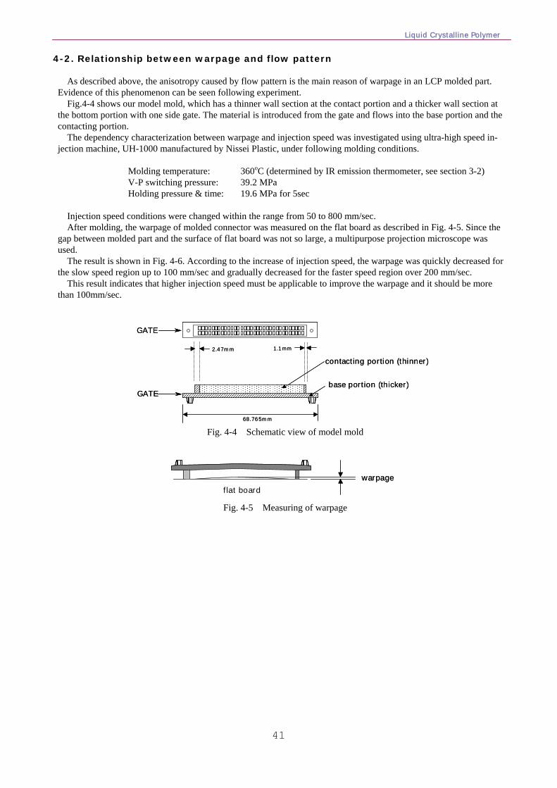
Liquid Crystalline Polymer
41
4-2. Relationship between warpage and flow pattern As described above, the anisotropy caused by flow pattern is the main reason of warpage in an LCP molded part.
Evidence of this phenomenon can be seen following experiment. Fig.4-4 shows our model mold, which has a thinner wall section at the contact portion and a thicker wall section at
the bottom portion with one side gate. The material is introduced from the gate and flows into the base portion and the contacting portion.
The dependency characterization between warpage and injection speed was investigated using ultra-high speed in-jection machine, UH-1000 manufactured by Nissei Plastic, under following molding conditions.
Molding temperature: 360oC (determined by IR emission thermometer, see section 3-2) V-P switching pressure: 39.2 MPa Holding pressure & time: 19.6 MPa for 5sec Injection speed conditions were changed within the range from 50 to 800 mm/sec. After molding, the warpage of molded connector was measured on the flat board as described in Fig. 4-5. Since the
gap between molded part and the surface of flat board was not so large, a multipurpose projection microscope was used.
The result is shown in Fig. 4-6. According to the increase of injection speed, the warpage was quickly decreased for the slow speed region up to 100 mm/sec and gradually decreased for the faster speed region over 200 mm/sec.
This result indicates that higher injection speed must be applicable to improve the warpage and it should be more than 100mm/sec.
GATE
GATE
contacting portion (thinner)
base portion (thicker)
2.47mm 1.1mm
68.765mm
GATE
GATE
contacting portion (thinner)
base portion (thicker)
2.47mm 1.1mm
68.765mm Fig. 4-4 Schematic view of model mold
warpageflat board
warpageflat board
Fig. 4-5 Measuring of warpage
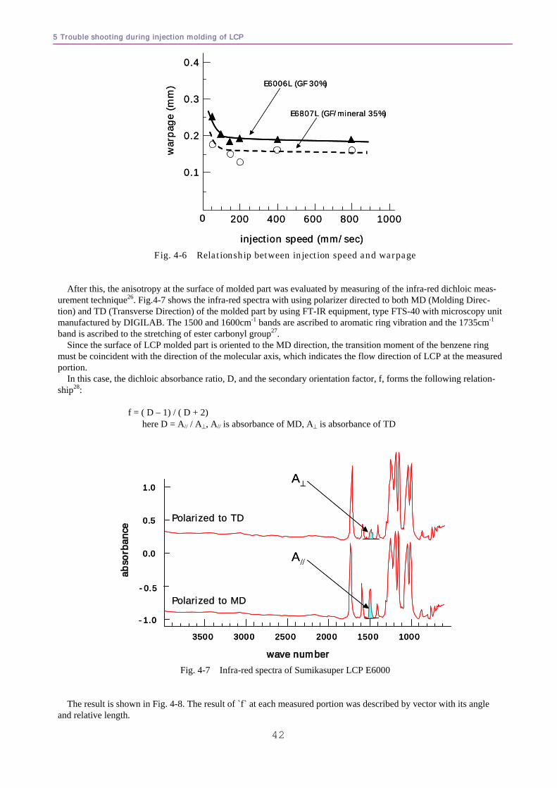
5 Trouble shooting during injection molding of LCP
42
E6006L (GF 30%)
E6807L (GF/mineral 35%)
0 200 400 600 800 1000
0.1
0.2
0.3
0.4
war
page
(mm
)
injection speed (mm/sec)
E6006L (GF 30%)
E6807L (GF/mineral 35%)
0 200 400 600 800 1000
0.1
0.2
0.3
0.4
war
page
(mm
)
injection speed (mm/sec) Fig. 4-6 Relationship between injection speed and warpage
After this, the anisotropy at the surface of molded part was evaluated by measuring of the infra-red dichloic meas-
urement technique26. Fig.4-7 shows the infra-red spectra with using polarizer directed to both MD (Molding Direc-tion) and TD (Transverse Direction) of the molded part by using FT-IR equipment, type FTS-40 with microscopy unit manufactured by DIGILAB. The 1500 and 1600cm-1 bands are ascribed to aromatic ring vibration and the 1735cm-1 band is ascribed to the stretching of ester carbonyl group27.
Since the surface of LCP molded part is oriented to the MD direction, the transition moment of the benzene ring must be coincident with the direction of the molecular axis, which indicates the flow direction of LCP at the measured portion.
In this case, the dichloic absorbance ratio, D, and the secondary orientation factor, f, forms the following relation-ship28:
f = ( D – 1) / ( D + 2) here D = A// / A⊥, A// is absorbance of MD, A⊥ is absorbance of TD
wave numberwave number
abso
rban
ceab
sorb
ance
-1.0
-0.5
0.0
0.5
1.0
3500 3000 2500 2000 1500 1000
Polarized to TDPolarized to TD
Polarized to MDPolarized to MD
A//
A⊥
wave numberwave number
abso
rban
ceab
sorb
ance
-1.0
-0.5
0.0
0.5
1.0
3500 3000 2500 2000 1500 1000
Polarized to TDPolarized to TD
Polarized to MDPolarized to MD
A//
A⊥
Fig. 4-7 Infra-red spectra of Sumikasuper LCP E6000
The result is shown in Fig. 4-8. The result of `f` at each measured portion was described by vector with its angle
and relative length.
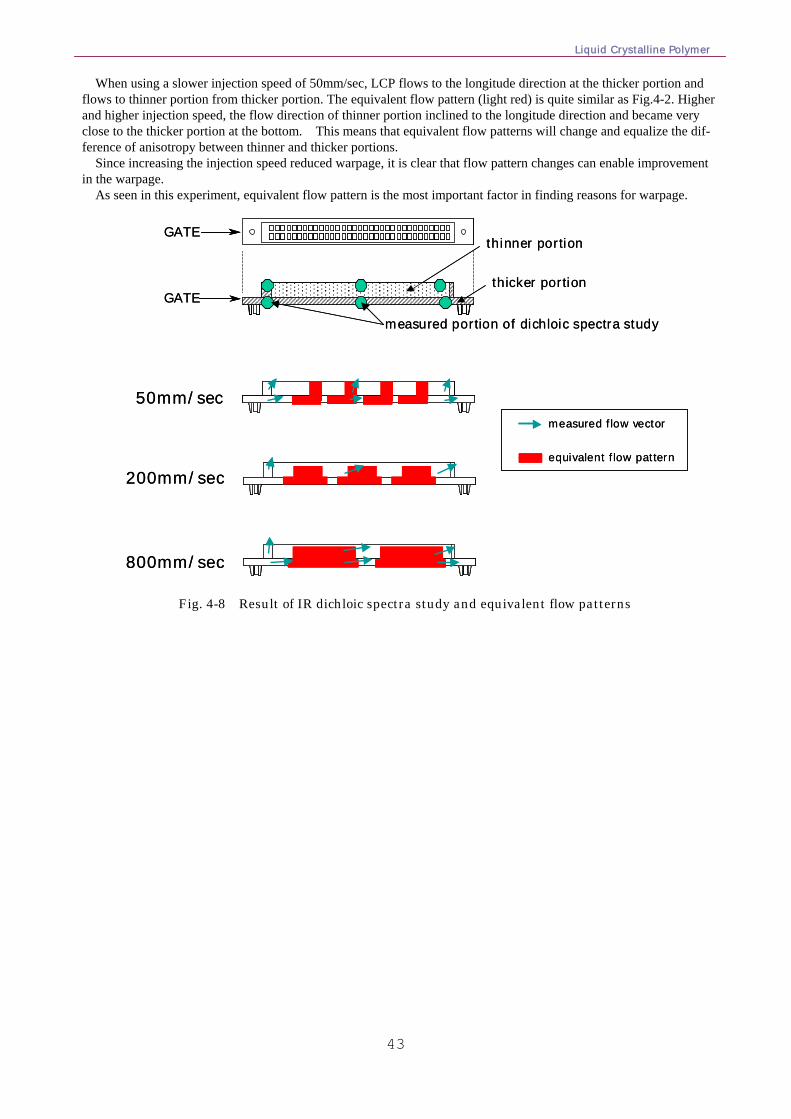
Liquid Crystalline Polymer
43
When using a slower injection speed of 50mm/sec, LCP flows to the longitude direction at the thicker portion and flows to thinner portion from thicker portion. The equivalent flow pattern (light red) is quite similar as Fig.4-2. Higher and higher injection speed, the flow direction of thinner portion inclined to the longitude direction and became very close to the thicker portion at the bottom. This means that equivalent flow patterns will change and equalize the dif-ference of anisotropy between thinner and thicker portions.
Since increasing the injection speed reduced warpage, it is clear that flow pattern changes can enable improvement in the warpage.
As seen in this experiment, equivalent flow pattern is the most important factor in finding reasons for warpage.
GATE
GATE
thinner portion
thicker portion
measured portion of dichloic spectra study
50mm/sec
200mm/sec
800mm/sec
measured flow vector
equivalent flow pattern
GATE
GATE
thinner portion
thicker portion
measured portion of dichloic spectra study
50mm/sec
200mm/sec
800mm/sec
measured flow vector
equivalent flow pattern
Fig. 4-8 Result of IR dichloic spectra study and equivalent flow patterns
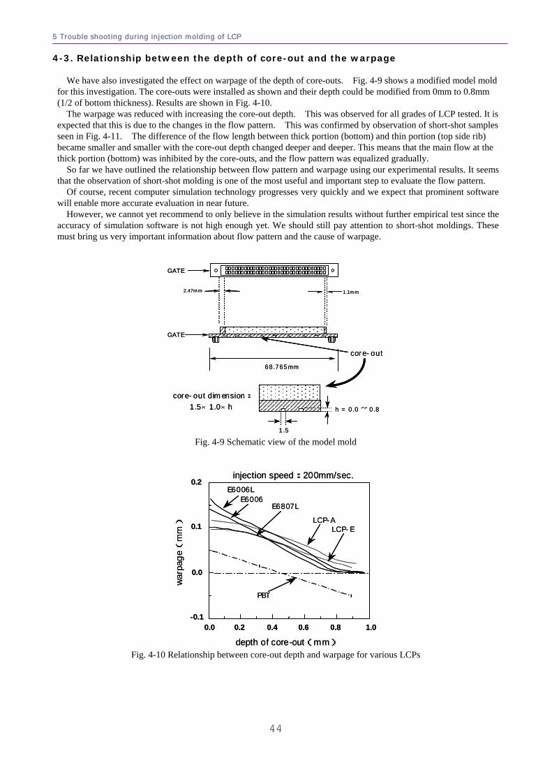
5 Trouble shooting during injection molding of LCP
44
4-3. Relationship between the depth of core-out and the warpage We have also investigated the effect on warpage of the depth of core-outs. Fig. 4-9 shows a modified model mold
for this investigation. The core-outs were installed as shown and their depth could be modified from 0mm to 0.8mm (1/2 of bottom thickness). Results are shown in Fig. 4-10.
The warpage was reduced with increasing the core-out depth. This was observed for all grades of LCP tested. It is expected that this is due to the changes in the flow pattern. This was confirmed by observation of short-shot samples seen in Fig. 4-11. The difference of the flow length between thick portion (bottom) and thin portion (top side rib) became smaller and smaller with the core-out depth changed deeper and deeper. This means that the main flow at the thick portion (bottom) was inhibited by the core-outs, and the flow pattern was equalized gradually.
So far we have outlined the relationship between flow pattern and warpage using our experimental results. It seems that the observation of short-shot molding is one of the most useful and important step to evaluate the flow pattern.
Of course, recent computer simulation technology progresses very quickly and we expect that prominent software will enable more accurate evaluation in near future.
However, we cannot yet recommend to only believe in the simulation results without further empirical test since the accuracy of simulation software is not high enough yet. We should still pay attention to short-shot moldings. These must bring us very important information about flow pattern and the cause of warpage.
68.765mm
1.1mm2.47mm
core-out
GATE
GATE
core-out dimension:1.5×1.0×h
1.5
h = 0.0 ~ 0.8
68.765mm
1.1mm2.47mm
core-out
GATE
GATE
core-out dimension:1.5×1.0×h
1.5
h = 0.0 ~ 0.8
Fig. 4-9 Schematic view of the model mold
-0.1
0.0
0.1
0.2
0.0 0.2 0.4 0.6 0.8 1.0
war
page(
mm)
depth of core-out(mm)
PBT
E6006LE6006
E6807L
LCP-ALCP-E
injection speed:200mm/sec.
-0.1
0.0
0.1
0.2
0.0 0.2 0.4 0.6 0.8 1.0
war
page(
mm)
depth of core-out(mm)
PBT
E6006LE6006
E6807L
LCP-ALCP-E
injection speed:200mm/sec.
Fig. 4-10 Relationship between core-out depth and warpage for various LCPs
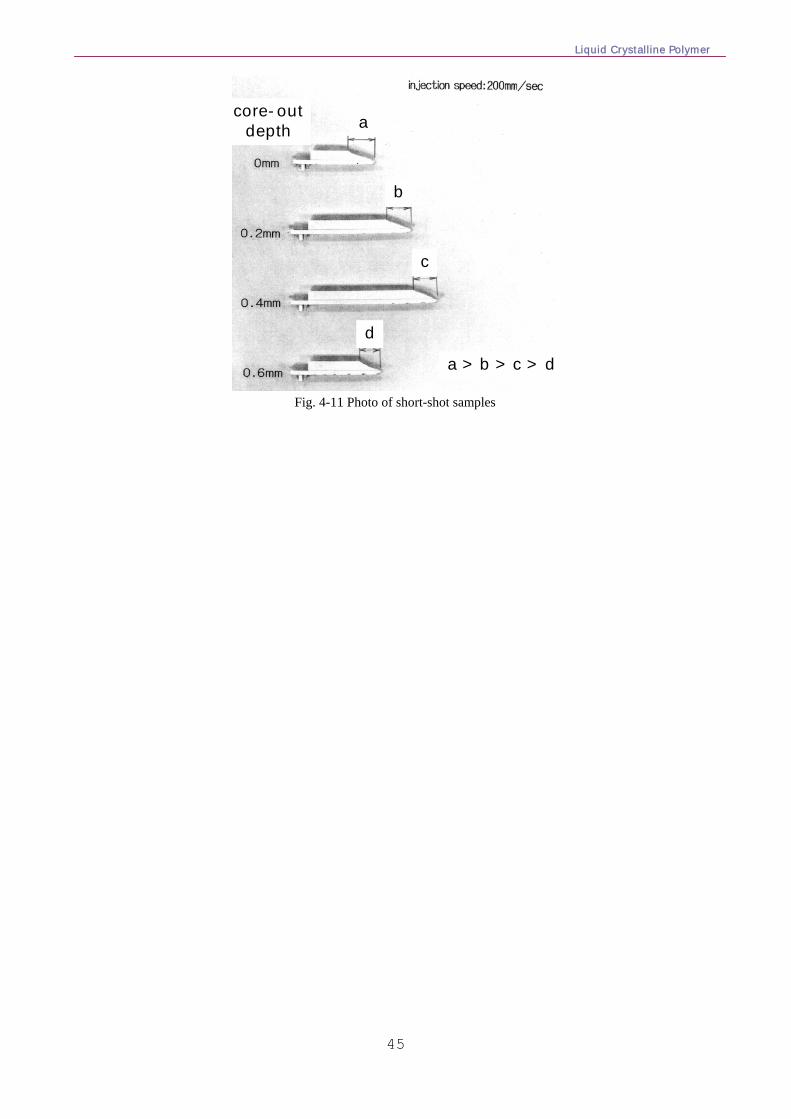
Liquid Crystalline Polymer
45
core-outdepth
a > b > c > d
a
b
c
d
core-outdepth
a > b > c > d
a
b
c
d
Fig. 4-11 Photo of short-shot samples
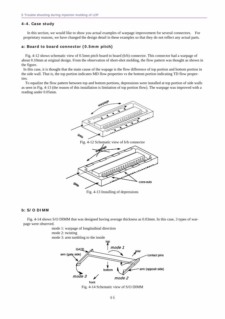
5 Trouble shooting during injection molding of LCP
46
4-4. Case study In this section, we would like to show you actual examples of warpage improvement for several connectors. For
proprietary reasons, we have changed the design detail in these examples so that they do not reflect any actual parts. a: Board to board connector (0.5mm pitch) Fig. 4-12 shows schematic view of 0.5mm pitch board to board (b/b) connector. This connector had a warpage of about 0.10mm at original design. From the observation of short-shot molding, the flow pattern was thought as shown in the figure. In this case, it is thought that the main cause of the wapage is the flow difference of top portion and bottom portion in the side wall. That is, the top portion indicates MD flow properties vs the bottom portion indicating TD flow proper-ties.
To equalize the flow pattern between top and bottom portions, depressions were installed at top portion of side walls as seen in Fig. 4-13 (the reason of this installation is limitation of top portion flow). The warpage was improved with a reading under 0.05mm.
gate
warpage
gate
warpage
Fig. 4-12 Schematic view of b/b connector
gate
warpage
core-outsgate
warpage
gate
warpage
core-outs
Fig. 4-13 Installing of depressions
b: S/O DIMM
Fig. 4-14 shows S/O DIMM that was designed having average thickness as 0.03mm. In this case, 3 types of war-
page were observed. mode 1: warpage of longitudinal direction mode 2: twisting mode 3: arm tumbling to the inside
GATE mode 1mode 1
mode 2mode 2mode 3mode 3
top
bottom
front
reararm (gate side)
arm (opposit side)
contact pins
GATE mode 1mode 1
mode 2mode 2mode 3mode 3
top
bottom
front
reararm (gate side)
arm (opposit side)
contact pins
Fig. 4-14 Schematic view of S/O DIMM
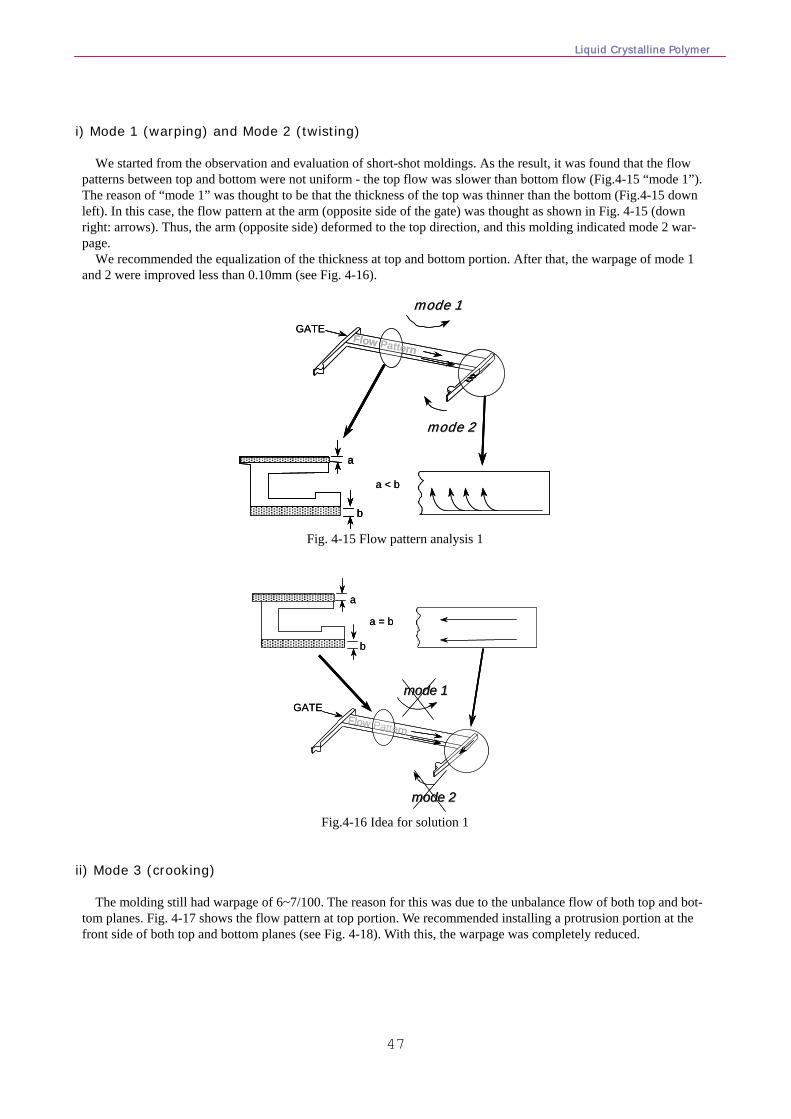
Liquid Crystalline Polymer
47
i) Mode 1 (warping) and Mode 2 (twisting)
We started from the observation and evaluation of short-shot moldings. As the result, it was found that the flow
patterns between top and bottom were not uniform - the top flow was slower than bottom flow (Fig.4-15 “mode 1”). The reason of “mode 1” was thought to be that the thickness of the top was thinner than the bottom (Fig.4-15 down left). In this case, the flow pattern at the arm (opposite side of the gate) was thought as shown in Fig. 4-15 (down right: arrows). Thus, the arm (opposite side) deformed to the top direction, and this molding indicated mode 2 war-page.
We recommended the equalization of the thickness at top and bottom portion. After that, the warpage of mode 1 and 2 were improved less than 0.10mm (see Fig. 4-16).
a
b
a < b
GATEFlow Pattern
mode 1mode 1
mode 2mode 2
a
b
a
b
a < b
GATEFlow Pattern
mode 1mode 1
mode 2mode 2
Fig. 4-15 Flow pattern analysis 1
a
b
a = b
GATEFlow Pattern
mode 1mode 1
mode 2mode 2
a
b
a = b
GATEFlow Pattern
mode 1mode 1
mode 2mode 2
Fig.4-16 Idea for solution 1 ii) Mode 3 (crooking)
The molding still had warpage of 6~7/100. The reason for this was due to the unbalance flow of both top and bot-tom planes. Fig. 4-17 shows the flow pattern at top portion. We recommended installing a protrusion portion at the front side of both top and bottom planes (see Fig. 4-18). With this, the warpage was completely reduced.
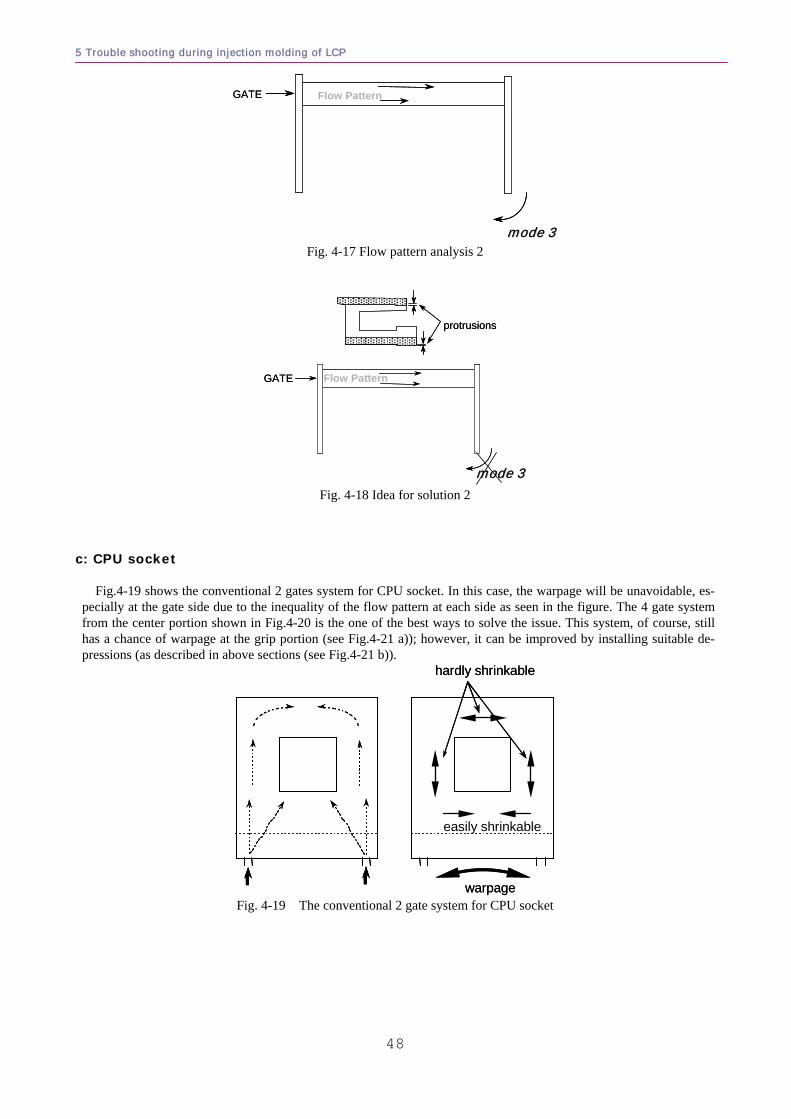
5 Trouble shooting during injection molding of LCP
48
GATE Flow Pattern
mode 3mode 3
GATE Flow Pattern
mode 3mode 3 Fig. 4-17 Flow pattern analysis 2
GATE Flow Pattern
mode 3mode 3
protrusions
GATE Flow Pattern
mode 3mode 3
protrusions
Fig. 4-18 Idea for solution 2
c: CPU socket
Fig.4-19 shows the conventional 2 gates system for CPU socket. In this case, the warpage will be unavoidable, es-
pecially at the gate side due to the inequality of the flow pattern at each side as seen in the figure. The 4 gate system from the center portion shown in Fig.4-20 is the one of the best ways to solve the issue. This system, of course, still has a chance of warpage at the grip portion (see Fig.4-21 a)); however, it can be improved by installing suitable de-pressions (as described in above sections (see Fig.4-21 b)).
easily shrinkable
hardly shrinkable
warpage
easily shrinkable
hardly shrinkable
warpage Fig. 4-19 The conventional 2 gate system for CPU socket
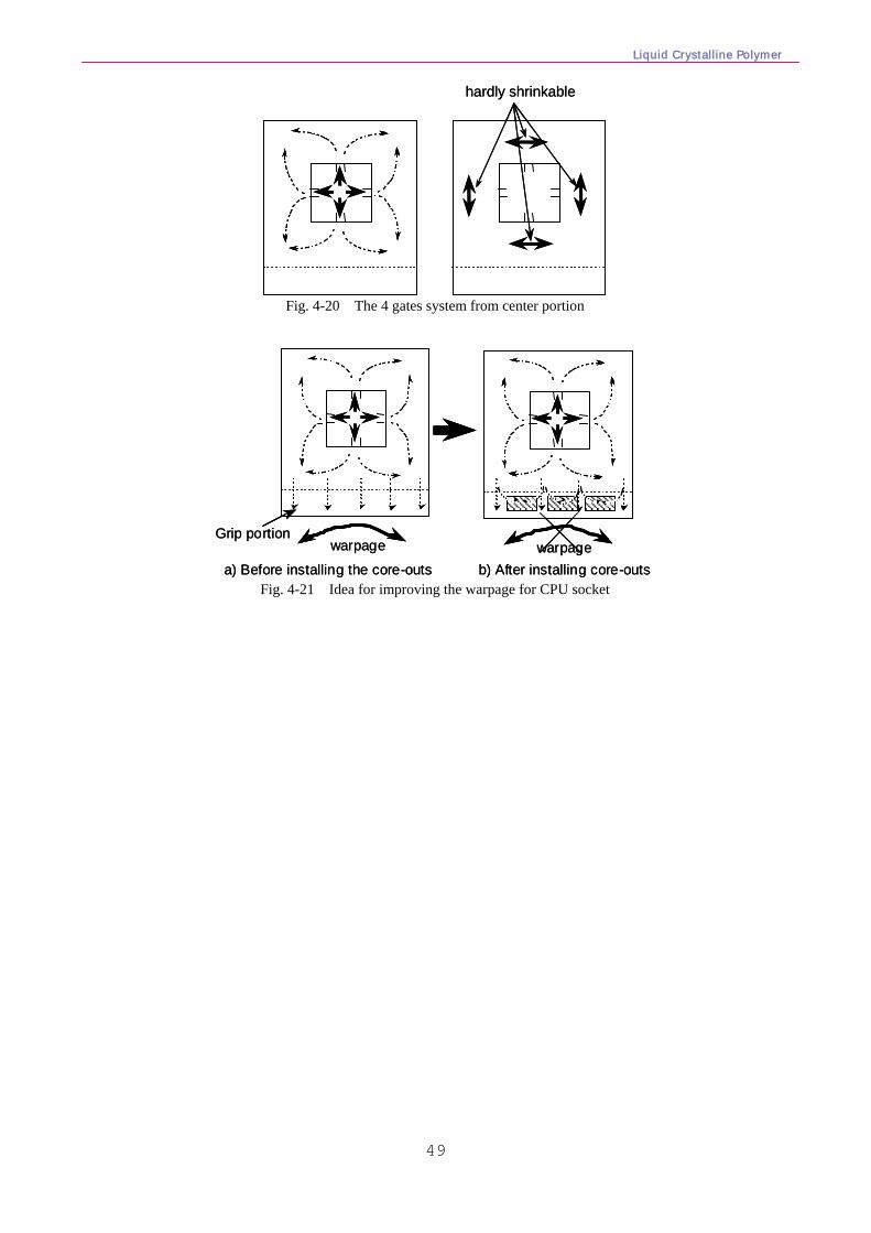
Liquid Crystalline Polymer
49
hardly shrinkablehardly shrinkable
Fig. 4-20 The 4 gates system from center portion
warpage
a) Before installing the core-outs b) After installing core-outswarpage
Grip portionwarpage
a) Before installing the core-outs b) After installing core-outswarpage
Grip portion
Fig. 4-21 Idea for improving the warpage for CPU socket
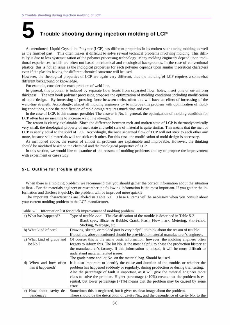
5 Trouble shooting during injection molding of LCP
50
As mentioned, Liquid Crystalline Polymer (LCP) has different properties in its molten state during molding as well as the finished part. This often makes it difficult to solve several technical problems involving molding. This diffi-culty is due to less systematization of the polymer processing technology. Many molding engineers depend upon tradi-tional experiences, which are often not based on chemical and rheological backgrounds. In the case of conventional plastics, this is not an issue as the rhological properties for each polymer depends upon similar theoretical characters even if the plastics having the different chemical structure will be used. However, the rheological properties of LCP are again very different, thus the molding of LCP requires a somewhat different background or knowledge.
For example, consider the crack problem of weld-line. In general, this problem is induced by separate flow fronts from separated flow, holes, insert pins or un-uniform
thickness. The text book polymer processing proposes the optimization of molding conditions including modification of mold design. By increasing of pressing force between melts, often this will have an effect of increasing of the weld-line strength. Accordingly, almost all molding engineers try to improve this problem with optimization of mold-ing conditions, since the modification of mold design requires much time and cost.
In the case of LCP, is this manner possible? The answer is No. In general, the optimization of molding condition for LCP often has no meaning to increase weld line strength.
The reason is clearly explainable. Since the difference between melt and molten state of LCP is thermodynamically very small, the rheological property of melt state and solid state of material is quite similar. This means that the melt of LCP is nearly equal to the solid of LCP. Accordingly, the once separated flow of LCP will not stick to each other any more, because solid materials will not stick each other. For this case, the modification of mold design is necessary. As mentioned above, the reason of almost all problems are explainable and improvable. However, the thinking should be modified based on the chemical and the rheological properties of LCP. In this section, we would like to examine of the reasons of molding problems and try to propose the improvement with experiment or case study. 5-1. Outline for trouble shooting When there is a molding problem, we recommend that you should gather the correct information about the situation at first. . For the materials engineer or researcher the following information is the most important. If you gather the in-formation and disclose it quickly, the problem will be improved more quickly. The important characteristics are labeled in Table 5.1. These 6 items will be necessary when you consult about your current molding problem to the LCP manufacturer. Table 5-1 Information list for quick improvement of molding problem a) What has happened? Type of trouble >>> The classification of the trouble is described in Table 5-2.
Black spec, Blister & Bubble, Crack, Flash, Flow mark, Metering, Short-shot, Sticking, Warpage, etc.
b) What kind of part? Drawing, sketch, or molded part is very helpful to think about the reason of trouble. If possible, above mentioned should be provided to material manufacturer’s engineer.
c) What kind of grade and lot No.?
Of course, this is the mane basic information, however, the molding engineer often forgets to inform this. The lot No. is the most helpful to chase the production history at the manufacturer’s factory. If this information is missed, it will be more difficult to understand material related issues. The grade name and lot No. on the material bag. Should be used.
d) When and how often has it happened?
It is also important to identify the cause and duration of the trouble, or whether the problem has happened suddenly or regularly, during production or during trial testing. Also the percentage of fault is important, as it will give the material engineer more clues to solve the problem. Higher percentage (>10%) means that the problem is es-sential, but lower percentage (<1%) means that the problem may be caused by some error.
e) How about cavity de-pendency?
Sometimes this is neglected, but it gives us clear image about the problem. There should be the description of cavity No., and the dependence of cavity No. to the
5 Trouble shooting during injection molding of LCP
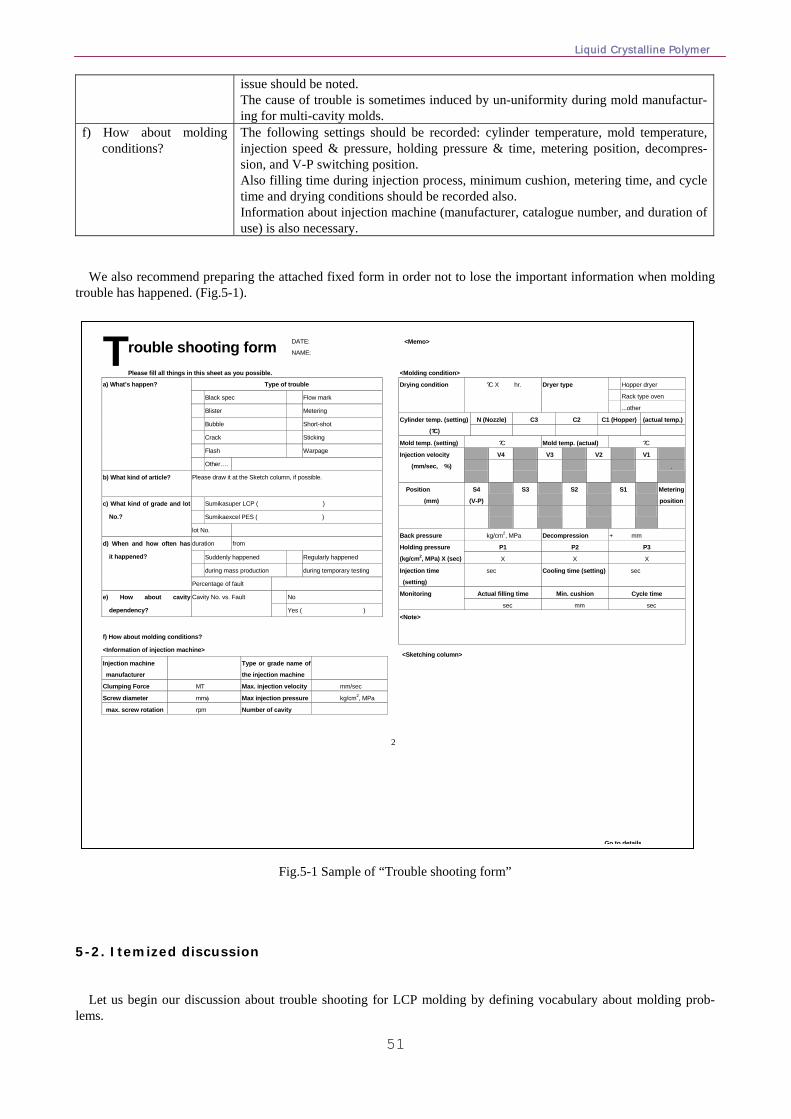
Liquid Crystalline Polymer
51
issue should be noted. The cause of trouble is sometimes induced by un-uniformity during mold manufactur-ing for multi-cavity molds.
f) How about molding conditions?
The following settings should be recorded: cylinder temperature, mold temperature, injection speed & pressure, holding pressure & time, metering position, decompres-sion, and V-P switching position. Also filling time during injection process, minimum cushion, metering time, and cycle time and drying conditions should be recorded also. Information about injection machine (manufacturer, catalogue number, and duration of use) is also necessary.
We also recommend preparing the attached fixed form in order not to lose the important information when molding trouble has happened. (Fig.5-1).
2
rouble shooting form
Please fill all things in this sheet as you possible.
Type of trouble
Black spec Flow mark
Blister Metering
Bubble Short-shot
Crack Sticking
Flash Warpage
a) What’s happen?
Other….
b) What kind of article? Please draw it at the Sketch column, if possible.
Sumikasuper LCP ( )
Sumikaexcel PES ( )
c) What kind of grade and lot
No.?
lot No.
duration from
Suddenly happened Regularly happened
during mass production during temporary testing
d) When and how often has
it happened?
Percentage of fault
No e) How about cavity
dependency?
Cavity No. vs. Fault
Yes ( )
f) How about molding conditions?
<Information of injection machine>
Injection machine
manufacturer
Type or grade name of
the injection machine
Clumping Force MT Max. injection velocity mm/sec
Screw diameter mmφ Max injection pressure kg/cm2, MPa
max. screw rotation rpm Number of cavity
<Molding condition>
Hopper dryer
Rack type oven
Drying condition ?C X hr. Dryer type
...other
N (Nozzle) C3 C2 C1 (Hopper) (actual temp.)Cylinder temp. (setting)
(?C)
Mold temp. (setting) ?C Mold temp. (actual) ?C
V4 V3 V2 V1 Injection velocity
(mm/sec, %)
.
Position
(mm)
S4
(V-P)
S3 S2 S1 Metering
position
Back pressure kg/cm2, MPa Decompression + mm
P1 P2 P3 Holding pressure
(kg/cm2, MPa) X (sec) X X X
Injection time
(setting)
sec Cooling time (setting) sec
Actual filling time Min. cushion Cycle time Monitoring
sec mm sec
<Note>
T
Go to details
DATE:
NAME:
<Sketching column>
<Memo>
Fig.5-1 Sample of “Trouble shooting form” 5-2. Itemized discussion
Let us begin our discussion about trouble shooting for LCP molding by defining vocabulary about molding prob-lems.
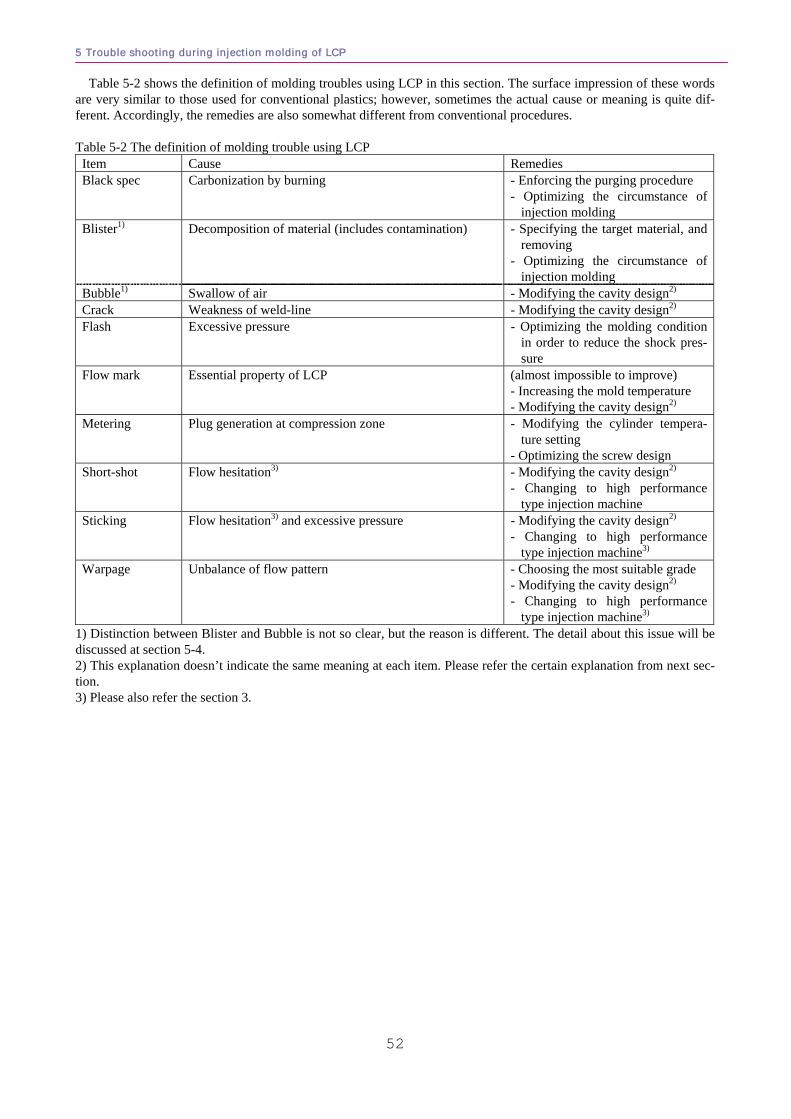
5 Trouble shooting during injection molding of LCP
52
Table 5-2 shows the definition of molding troubles using LCP in this section. The surface impression of these words are very similar to those used for conventional plastics; however, sometimes the actual cause or meaning is quite dif-ferent. Accordingly, the remedies are also somewhat different from conventional procedures. Table 5-2 The definition of molding trouble using LCP Item Cause Remedies Black spec Carbonization by burning - Enforcing the purging procedure
- Optimizing the circumstance of injection molding
Blister1) Decomposition of material (includes contamination) - Specifying the target material, and removing
- Optimizing the circumstance of injection molding
Bubble1) Swallow of air - Modifying the cavity design2) Crack Weakness of weld-line - Modifying the cavity design2) Flash Excessive pressure - Optimizing the molding condition
in order to reduce the shock pres-sure
Flow mark Essential property of LCP (almost impossible to improve) - Increasing the mold temperature - Modifying the cavity design2)
Metering Plug generation at compression zone - Modifying the cylinder tempera-ture setting
- Optimizing the screw design Short-shot Flow hesitation3) - Modifying the cavity design2)
- Changing to high performance type injection machine
Sticking Flow hesitation3) and excessive pressure - Modifying the cavity design2) - Changing to high performance
type injection machine3) Warpage Unbalance of flow pattern - Choosing the most suitable grade
- Modifying the cavity design2) - Changing to high performance
type injection machine3) 1) Distinction between Blister and Bubble is not so clear, but the reason is different. The detail about this issue will be discussed at section 5-4. 2) This explanation doesn’t indicate the same meaning at each item. Please refer the certain explanation from next sec-tion. 3) Please also refer the section 3.
Liquid Crystalline Polymer
53
5-3. Black spec
The generation of black spec is often observed in higher thermal stability grades of LCP, for example Sumikasuper E4000 series and E5000 series. The cause of this is due to the viscosity properties of LCP and the thermal stability.
As explained at section 1-3 and 3-3, melt LCP is difficult to be processed from flow prevention structures, dead zones, etc. Examples of this are the dead space of a manifold in hot runner systems, or the valve structures of a shut-off nozzle. In these areas, the former LCP will not be pushed out or replaced, and it will remain for a long dura-tion.
LCP has excellent thermal stability; however, this remaining portion of LCP will be damaged gradually. In time, it will become carbonized material by thermal decomposition reaction. This is one of the reasons for black specs.
Another reason is the relationship between molding temperature and decomposition temperature. As explained at section 1-2, LCP decompose at over 500oC, and this temperature is thought as the upper limit of organic materials. Higher thermal stability grades such as Sumikasuper E4000 series and E5000 series have molding temperature of 380 or 400oC. Since such higher molding temperature is very close to its decomposition temperature, this circumstance is very severe for the material, even if it has excellent thermal stability. If the material is exposed at these conditions for long time, the decomposition can not be prevented.
Accordingly, the best way to improve this problem is to remove the possibility of retention under molding tempera-ture (please also refer the section 5-4-(2)-b and 5-4-(2)-c).
The first step of improvement is to remove the reason. In general, we search and find the flow prevention structure. In this meaning, we recommend not to use the hot runner system and shut-off valve structure of injection machine. If you wish or plan to use these, you must think about the risk of black spec.
The second step is the cleaning of inside parts of cylinder, especially nozzle and the tip parts of screw. Usually, re-placing to the new parts is strongly recommended. Since the tip parts of screw must be worn out with long term using and molding with glass filled material, the clearance between inside surface of the cylinder should become bigger. This clearance difference will be also the cause of unstable metering and short-shot.
The third step is the purging. To make a habit of purging regularly is preferable to prevent the generation of black spec. The details are described at section 5-4-(2)-f.
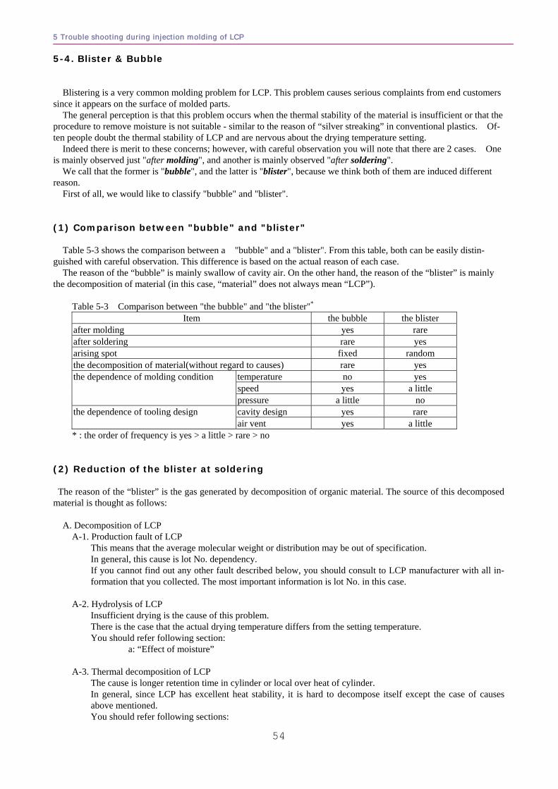
5 Trouble shooting during injection molding of LCP
54
5-4. Blister & Bubble Blistering is a very common molding problem for LCP. This problem causes serious complaints from end customers since it appears on the surface of molded parts.
The general perception is that this problem occurs when the thermal stability of the material is insufficient or that the procedure to remove moisture is not suitable - similar to the reason of “silver streaking” in conventional plastics. Of-ten people doubt the thermal stability of LCP and are nervous about the drying temperature setting.
Indeed there is merit to these concerns; however, with careful observation you will note that there are 2 cases. One is mainly observed just "after molding", and another is mainly observed "after soldering".
We call that the former is "bubble", and the latter is "blister", because we think both of them are induced different reason. First of all, we would like to classify "bubble" and "blister". (1) Comparison between "bubble" and "blister" Table 5-3 shows the comparison between a "bubble" and a "blister". From this table, both can be easily distin-guished with careful observation. This difference is based on the actual reason of each case.
The reason of the “bubble” is mainly swallow of cavity air. On the other hand, the reason of the “blister” is mainly the decomposition of material (in this case, “material” does not always mean “LCP”). Table 5-3 Comparison between "the bubble" and "the blister"*
Item the bubble the blister after molding yes rare after soldering rare yes arising spot fixed random the decomposition of material(without regard to causes) rare yes the dependence of molding condition temperature no yes
speed yes a little pressure a little no
the dependence of tooling design cavity design yes rare air vent yes a little
* : the order of frequency is yes > a little > rare > no (2) Reduction of the blister at soldering The reason of the “blister” is the gas generated by decomposition of organic material. The source of this decomposed material is thought as follows:
A. Decomposition of LCP A-1. Production fault of LCP
This means that the average molecular weight or distribution may be out of specification. In general, this cause is lot No. dependency. If you cannot find out any other fault described below, you should consult to LCP manufacturer with all in-formation that you collected. The most important information is lot No. in this case.
A-2. Hydrolysis of LCP
Insufficient drying is the cause of this problem. There is the case that the actual drying temperature differs from the setting temperature. You should refer following section:
a: “Effect of moisture”
A-3. Thermal decomposition of LCP The cause is longer retention time in cylinder or local over heat of cylinder. In general, since LCP has excellent heat stability, it is hard to decompose itself except the case of causes above mentioned. You should refer following sections:
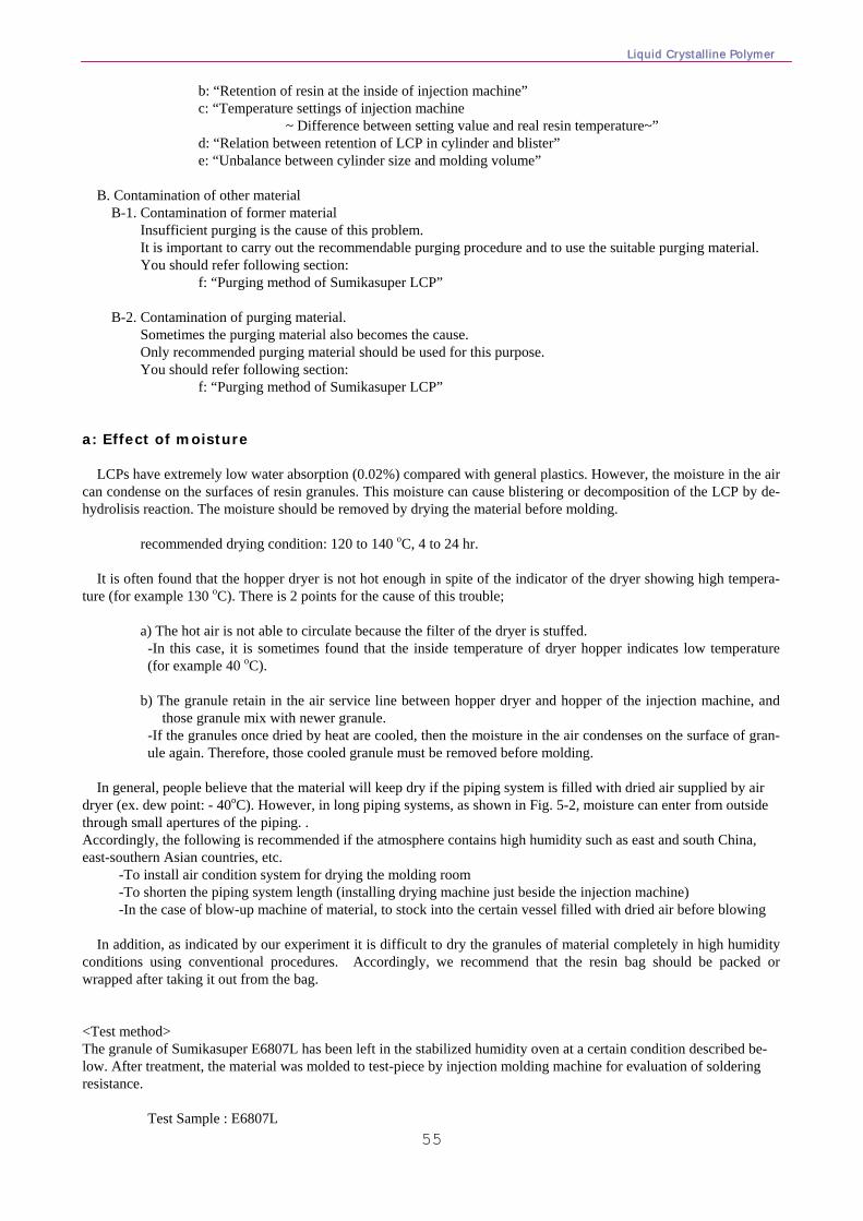
Liquid Crystalline Polymer
55
b: “Retention of resin at the inside of injection machine” c: “Temperature settings of injection machine
~ Difference between setting value and real resin temperature~” d: “Relation between retention of LCP in cylinder and blister” e: “Unbalance between cylinder size and molding volume”
B. Contamination of other material
B-1. Contamination of former material Insufficient purging is the cause of this problem. It is important to carry out the recommendable purging procedure and to use the suitable purging material. You should refer following section:
f: “Purging method of Sumikasuper LCP” B-2. Contamination of purging material.
Sometimes the purging material also becomes the cause. Only recommended purging material should be used for this purpose. You should refer following section:
f: “Purging method of Sumikasuper LCP” a: Effect of moisture LCPs have extremely low water absorption (0.02%) compared with general plastics. However, the moisture in the air can condense on the surfaces of resin granules. This moisture can cause blistering or decomposition of the LCP by de-hydrolisis reaction. The moisture should be removed by drying the material before molding. recommended drying condition: 120 to 140 oC, 4 to 24 hr. It is often found that the hopper dryer is not hot enough in spite of the indicator of the dryer showing high tempera-ture (for example 130 oC). There is 2 points for the cause of this trouble;
a) The hot air is not able to circulate because the filter of the dryer is stuffed. -In this case, it is sometimes found that the inside temperature of dryer hopper indicates low temperature (for example 40 oC).
b) The granule retain in the air service line between hopper dryer and hopper of the injection machine, and
those granule mix with newer granule. -If the granules once dried by heat are cooled, then the moisture in the air condenses on the surface of gran-ule again. Therefore, those cooled granule must be removed before molding.
In general, people believe that the material will keep dry if the piping system is filled with dried air supplied by air
dryer (ex. dew point: - 40oC). However, in long piping systems, as shown in Fig. 5-2, moisture can enter from outside through small apertures of the piping. . Accordingly, the following is recommended if the atmosphere contains high humidity such as east and south China, east-southern Asian countries, etc. -To install air condition system for drying the molding room -To shorten the piping system length (installing drying machine just beside the injection machine) -In the case of blow-up machine of material, to stock into the certain vessel filled with dried air before blowing
In addition, as indicated by our experiment it is difficult to dry the granules of material completely in high humidity conditions using conventional procedures. Accordingly, we recommend that the resin bag should be packed or wrapped after taking it out from the bag. <Test method> The granule of Sumikasuper E6807L has been left in the stabilized humidity oven at a certain condition described be-low. After treatment, the material was molded to test-piece by injection molding machine for evaluation of soldering resistance.
Test Sample : E6807L
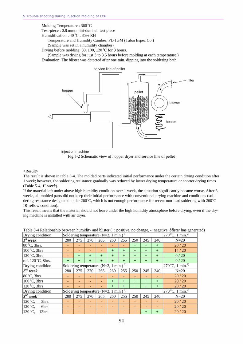
5 Trouble shooting during injection molding of LCP
56
Molding Temperature : 360 oC Test-piece : 0.8 mmt mini-dumbell test piece Humidification : 40 oC , 85% RH Temperature and Humidity Camber: PL-1GM (Tabai Espec Co.) (Sample was set in a humidity chamber) Drying before molding: 80, 100, 120 oC for 3 hours. (Sample was drying for just 3 to 3.5 hours before molding at each temperature.) Evaluation: The blister was detected after one min. dipping into the soldering bath.
heater
blower
filter
pellet
injection machine
hopper
service line of pellet
Fig.5-2 Schematic view of hopper dryer and service line of pellet
<Result> The result is shown in table 5-4. The molded parts indicated initial performance under the certain drying condition after 1 week; however, the soldering resistance gradually was reduced by lower drying temperature or shorter drying times (Table 5-4, 1st week). If the material left under above high humidity condition over 1 week, the situation significantly became worse. After 3 weeks, all molded parts did not keep their initial performance with conventional drying machine and conditions (sol-dering resistance designated under 260oC, which is not enough performance for recent non-lead soldering with 260oC IR-reflow condition). This result means that the material should not leave under the high humidity atmosphere before drying, even if the dry-ing machine is installed with air dryer. Table 5-4 Relationship between humidity and blister (+: positive, no change, -: negative, blister has generated) Drying condition Soldering temperature (N=2, 1 min.) 1) 270 oC, 1 min.2) 1st week 280 275 270 265 260 255 250 245 240 N=20 80 oC, 3hrs. - - - - - - + + + 20 / 20 100 oC, 3hrs - - - - + + + + + 14 / 20 120 oC, 3hrs - + + + + + + + + 0 / 20 ref. 120 oC, 8hrs. + + + + + + + + + 0 / 20 Drying condition Soldering temperature (N=2, 1 min.) 1) 270 oC, 1 min.2) 2nd week 280 275 270 265 260 255 250 245 240 N=20 80 oC, 3hrs. - - - - - - - - - 20 / 20 100 oC, 3hrs - - - - + + + + + 20 / 20 120 oC, 3hrs - - - - + + + + + 20 / 20 Drying condition Soldering temperature (N=2, 1 min.) 1) 270 oC, 1 min.2) 3rd week 3) 280 275 270 265 260 255 250 245 240 N=20 120 oC, 3hrs. - - - - - - - - - 20 / 20 120 oC, 6hrs - - - - - - - - - 20 / 20 120 oC, 12hrs - - - - - - - + + 20 / 20
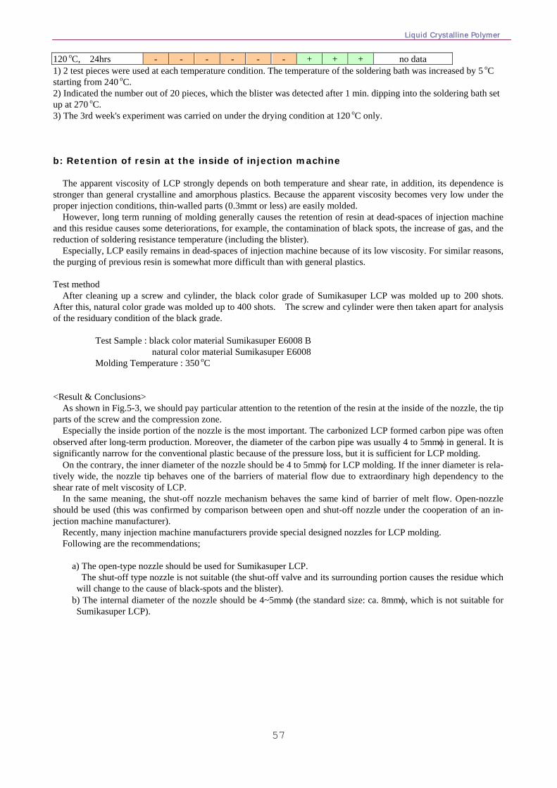
Liquid Crystalline Polymer
57
120 oC, 24hrs - - - - - - + + + no data 1) 2 test pieces were used at each temperature condition. The temperature of the soldering bath was increased by 5 oC starting from 240 oC. 2) Indicated the number out of 20 pieces, which the blister was detected after 1 min. dipping into the soldering bath set up at 270 oC. 3) The 3rd week's experiment was carried on under the drying condition at 120 oC only. b: Retention of resin at the inside of injection machine The apparent viscosity of LCP strongly depends on both temperature and shear rate, in addition, its dependence is stronger than general crystalline and amorphous plastics. Because the apparent viscosity becomes very low under the proper injection conditions, thin-walled parts (0.3mmt or less) are easily molded. However, long term running of molding generally causes the retention of resin at dead-spaces of injection machine and this residue causes some deteriorations, for example, the contamination of black spots, the increase of gas, and the reduction of soldering resistance temperature (including the blister). Especially, LCP easily remains in dead-spaces of injection machine because of its low viscosity. For similar reasons, the purging of previous resin is somewhat more difficult than with general plastics. Test method After cleaning up a screw and cylinder, the black color grade of Sumikasuper LCP was molded up to 200 shots. After this, natural color grade was molded up to 400 shots. The screw and cylinder were then taken apart for analysis of the residuary condition of the black grade.
Test Sample : black color material Sumikasuper E6008 B natural color material Sumikasuper E6008 Molding Temperature : 350 oC
<Result & Conclusions> As shown in Fig.5-3, we should pay particular attention to the retention of the resin at the inside of the nozzle, the tip parts of the screw and the compression zone. Especially the inside portion of the nozzle is the most important. The carbonized LCP formed carbon pipe was often observed after long-term production. Moreover, the diameter of the carbon pipe was usually 4 to 5mmφ in general. It is significantly narrow for the conventional plastic because of the pressure loss, but it is sufficient for LCP molding. On the contrary, the inner diameter of the nozzle should be 4 to 5mmφ for LCP molding. If the inner diameter is rela-tively wide, the nozzle tip behaves one of the barriers of material flow due to extraordinary high dependency to the shear rate of melt viscosity of LCP. In the same meaning, the shut-off nozzle mechanism behaves the same kind of barrier of melt flow. Open-nozzle should be used (this was confirmed by comparison between open and shut-off nozzle under the cooperation of an in-jection machine manufacturer).
Recently, many injection machine manufacturers provide special designed nozzles for LCP molding. Following are the recommendations;
a) The open-type nozzle should be used for Sumikasuper LCP. The shut-off type nozzle is not suitable (the shut-off valve and its surrounding portion causes the residue which
will change to the cause of black-spots and the blister). b) The internal diameter of the nozzle should be 4~5mmφ (the standard size: ca. 8mmφ, which is not suitable for
Sumikasuper LCP).
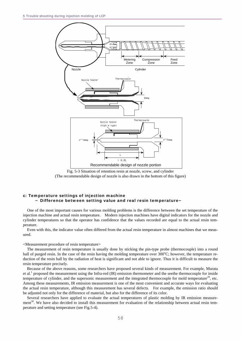
5 Trouble shooting during injection molding of LCP
58
Nozzle Cylinder
Metering Zone
Compression Zone
Feed Zone
8mmφ
ThermocoupleNozzle heater
Recommendable design of nozzle portion
4~5mmφ2~3mmφ
ThermocoupleNozzle heater
(High W type)
L
> 0.8L
Fig. 5-3 Situation of retention resin at nozzle, screw, and cylinder
(The recommendable design of nozzle is also drawn in the bottom of this figure) c: Temperature settings of injection machine
~ Difference between setting value and real resin temperature~ One of the most important causes for various molding problems is the difference between the set temperature of the injection machine and actual resin temperature. Modern injection machines have digital indicators for the nozzle and cylinder temperatures so that the operator has confidence that the values recorded are equal to the actual resin tem-perature. Even with this, the indicator value often differed from the actual resin temperature in almost machines that we meas-ured. <Measurement procedure of resin temperature> The measurement of resin temperature is usually done by sticking the pin-type probe (thermocouple) into a round ball of purged resin. In the case of the resin having the molding temperature over 300oC; however, the temperature re-duction of the resin ball by the radiation of heat is significant and not able to ignore. Thus it is difficult to measure the resin temperature precisely.
Because of the above reasons, some researchers have proposed several kinds of measurement. For example, Murata et al.1 proposed the measurement using the Infra-red (IR) emission thermometer and the seethe thermocouple for inside temperature of cylinder, and the supersonic measurement and the integrated thermocouple for mold temperature29, etc. Among these measurements, IR emission measurement is one of the most convenient and accurate ways for evaluating the actual resin temperature, although this measurement has several defects. For example, the emission ratio should be adjusted not only for the difference of material, but also for the difference of its color.
Several researchers have applied to evaluate the actual temperatures of plastic molding by IR emission measure-ment30. We have also decided to install this measurement for evaluation of the relationship between actual resin tem-perature and setting temperature (see Fig.5-4).
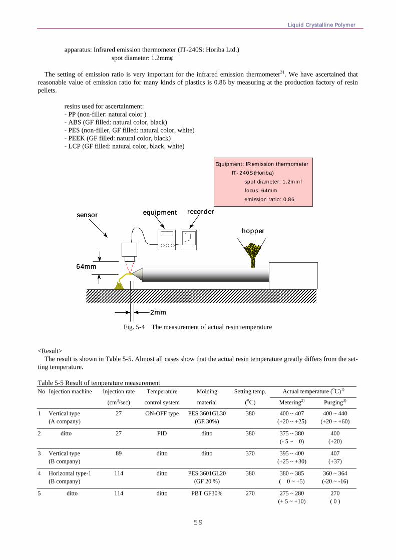
Liquid Crystalline Polymer
59
apparatus: Infrared emission thermometer (IT-240S: Horiba Ltd.) spot diameter: 1.2mmφ The setting of emission ratio is very important for the infrared emission thermometer31. We have ascertained that reasonable value of emission ratio for many kinds of plastics is 0.86 by measuring at the production factory of resin pellets.
resins used for ascertainment: - PP (non-filler: natural color ) - ABS (GF filled: natural color, black) - PES (non-filler, GF filled: natural color, white) - PEEK (GF filled: natural color, black) - LCP (GF filled: natural color, black, white)
sensor equipment recorder
hopper
Equipment: IR emission thermometerIT-240S (Horiba)
spot diameter: 1.2mmf focus: 64mm emission ratio: 0.86
64mm
2mm
sensor equipment recorder
hopper
Equipment: IR emission thermometerIT-240S (Horiba)
spot diameter: 1.2mmf focus: 64mm emission ratio: 0.86
64mm
2mm
Fig. 5-4 The measurement of actual resin temperature <Result> The result is shown in Table 5-5. Almost all cases show that the actual resin temperature greatly differs from the set-ting temperature. Table 5-5 Result of temperature measurement No Injection machine Injection rate Temperature Molding Setting temp. Actual temperature (oC)1)
(cm3/sec) control system material (oC) Metering2) Purging3)
1 Vertical type (A company)
27 ON-OFF type PES 3601GL30(GF 30%)
380 400 ~ 407 (+20 ~ +25)
400 ~ 440 (+20 ~ +60)
2 ditto 27 PID ditto 380 375 ~ 380 (- 5 ~ 0)
400 (+20)
3 Vertical type (B company)
89 ditto ditto 370 395 ~ 400 (+25 ~ +30)
407 (+37)
4 Horizontal type-1 (B company)
114 ditto PES 3601GL20(GF 20 %)
380 380 ~ 385 ( 0 ~ +5)
360 ~ 364 (-20 ~ -16)
5 ditto 114 ditto PBT GF30% 270 275 ~ 280 (+ 5 ~ +10)
270 ( 0 )
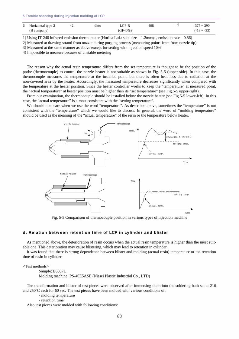
5 Trouble shooting during injection molding of LCP
60
6 Horizontal type-2 (B company)
42 ditto LCP-R (GF40%)
408 ---4) 375 ~ 390 (-18 ~ -33)
1) Using IT-240 infrared emission thermometer (Horiba Ltd.: spot size 1.2mmφ, emission rate 0.86) 2) Measured at drawing strand from nozzle during purging process (measuring point: 1mm from nozzle tip) 3) Measured at the same manner as above except for setting with injection speed 10% 4) Impossible to measure because of unstable metering The reason why the actual resin temperature differs from the set temperature is thought to be the position of the probe (thermocouple) to control the nozzle heater is not suitable as shown in Fig. 5-5 (upper side). In this case, the thermocouple measures the temperature at the installed point, but there is often heat loss due to radiation at the non-covered area by the heater. Accordingly, the measured temperature decreases significantly when compared with the temperature at the heater position. Since the heater controller works to keep the “temperature” at measured point, the “actual temperature” at heater position must be higher than its “set temperature” (see Fig.5-5 upper-right).
From our examination, the thermocouple should be installed below the nozzle heater (see Fig.5-5 lower-left). In this case, the “actual temperature” is almost consistent with the “setting temperature”.
We should take care when we use the word “temperature”. As described above, sometimes the “temperature” is not consistent with the “temperature” which we would like to discuss. In general, the word of “molding temperature” should be used as the meaning of the “actual temperature” of the resin or the temperature below heater.
Heat
ThermocoupleNozzle heater
setting temp.
deviation ≒+20~30 ℃
ThermocoupleNozzle heater
setting temp.
Temp.
Time
Temp.
Time
actual temp.
actual temp.
Fig. 5-5 Comparison of thermocouple position in various types of injection machine
d: Relation between retention time of LCP in cylinder and blister As mentioned above, the deterioration of resin occurs when the actual resin temperature is higher than the most suit-able one. This deterioration may cause blistering, which may lead to retention in cylinder. It was found that there is strong dependence between blister and molding (actual resin) temperature or the retention time of resin in cylinder. <Test methods> Sample: E6807L Molding machine: PS-40E5ASE (Nissei Plastic Industrial Co., LTD) The transformation and blister of test pieces were observed after immersing them into the soldering bath set at 210 and 250oC each for 60 sec. The test pieces have been molded with various conditions of: - molding temperature - retention time Also test pieces were molded with following conditions:
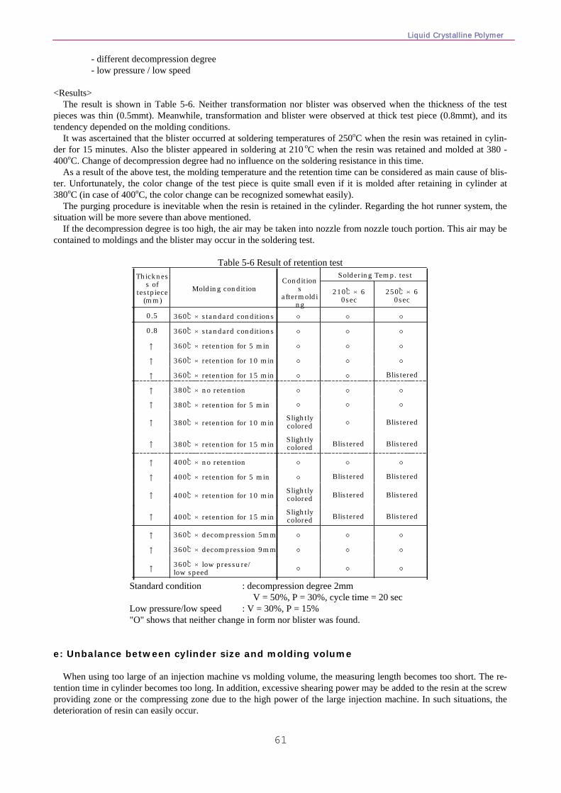
Liquid Crystalline Polymer
61
- different decompression degree - low pressure / low speed <Results> The result is shown in Table 5-6. Neither transformation nor blister was observed when the thickness of the test pieces was thin (0.5mmt). Meanwhile, transformation and blister were observed at thick test piece (0.8mmt), and its tendency depended on the molding conditions. It was ascertained that the blister occurred at soldering temperatures of 250oC when the resin was retained in cylin-der for 15 minutes. Also the blister appeared in soldering at 210 oC when the resin was retained and molded at 380 - 400oC. Change of decompression degree had no influence on the soldering resistance in this time. As a result of the above test, the molding temperature and the retention time can be considered as main cause of blis-ter. Unfortunately, the color change of the test piece is quite small even if it is molded after retaining in cylinder at 380oC (in case of 400oC, the color change can be recognized somewhat easily). The purging procedure is inevitable when the resin is retained in the cylinder. Regarding the hot runner system, the situation will be more severe than above mentioned. If the decompression degree is too high, the air may be taken into nozzle from nozzle touch portion. This air may be contained to moldings and the blister may occur in the soldering test.
Table 5-6 Result of retention test
○○○360℃×low pressure/ low speed↑
○○○360℃×decompression 9mm↑
○○○360℃×decompression 5mm↑
BlisteredBlisteredSlightlycolored400℃×retention for 15 min↑
BlisteredBlisteredSlightlycolored400℃×retention for 10 min↑
BlisteredBlistered○400℃×retention for 5 min↑
○○○400℃×no retention↑
BlisteredBlisteredSlightlycolored380℃×retention for 15 min↑
Blistered○Slightlycolored380℃×retention for 10 min↑
○○○380℃×retention for 5 min↑
○○○380℃×no retention↑
Blistered○○360℃×retention for 15 min↑
○○○360℃×retention for 10 min↑
○○○360℃×retention for 5 min↑
○○○360℃×standard conditions0.8
○○○360℃×standard conditions0.5
250℃×60sec
210℃×60sec
Soldering Temp. testCondition
s aftermoldi
ng
Molding condition
Thickness of
testpiece(mm)
Standard condition : decompression degree 2mm V = 50%, P = 30%, cycle time = 20 sec Low pressure/low speed : V = 30%, P = 15% "O" shows that neither change in form nor blister was found. e: Unbalance between cylinder size and molding volume When using too large of an injection machine vs molding volume, the measuring length becomes too short. The re-tention time in cylinder becomes too long. In addition, excessive shearing power may be added to the resin at the screw providing zone or the compressing zone due to the high power of the large injection machine. In such situations, the deterioration of resin can easily occur.
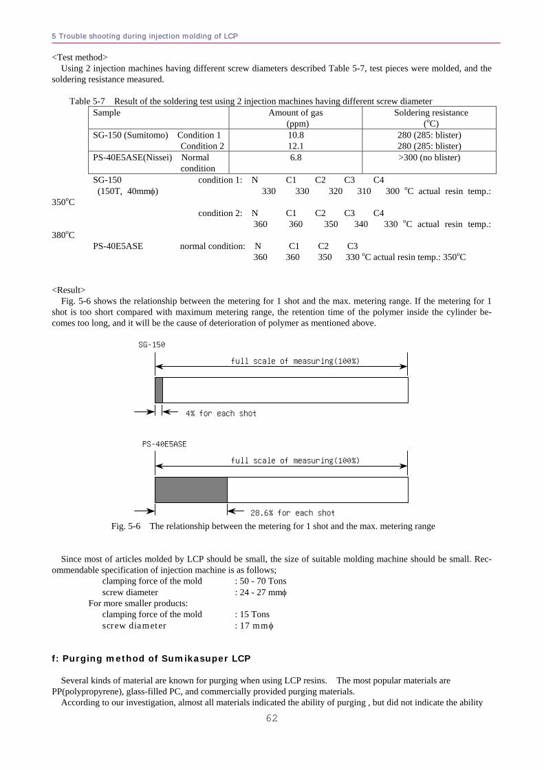
5 Trouble shooting during injection molding of LCP
62
<Test method> Using 2 injection machines having different screw diameters described Table 5-7, test pieces were molded, and the soldering resistance measured.
Table 5-7 Result of the soldering test using 2 injection machines having different screw diameter Sample Amount of gas
(ppm) Soldering resistance
(oC) SG-150 (Sumitomo) Condition 1 Condition 2
10.8 12.1
280 (285: blister) 280 (285: blister)
PS-40E5ASE(Nissei) Normal condition
6.8 >300 (no blister)
SG-150 condition 1: N C1 C2 C3 C4 (150T, 40mmφ) 330 330 320 310 300 oC actual resin temp.:
350oC condition 2: N C1 C2 C3 C4 360 360 350 340 330 oC actual resin temp.: 380oC PS-40E5ASE normal condition: N C1 C2 C3 360 360 350 330 oC actual resin temp.: 350oC <Result> Fig. 5-6 shows the relationship between the metering for 1 shot and the max. metering range. If the metering for 1 shot is too short compared with maximum metering range, the retention time of the polymer inside the cylinder be-comes too long, and it will be the cause of deterioration of polymer as mentioned above.
full scale of measuring(100%)
4% for each shot
SG-150
PS-40E5ASE
full scale of measuring(100%)
28.6% for each shot Fig. 5-6 The relationship between the metering for 1 shot and the max. metering range
Since most of articles molded by LCP should be small, the size of suitable molding machine should be small. Rec-ommendable specification of injection machine is as follows; clamping force of the mold : 50 - 70 Tons screw diameter : 24 - 27 mmφ For more smaller products: clamping force of the mold : 15 Tons screw diameter : 17 mmφ f: Purging method of Sumikasuper LCP
Several kinds of material are known for purging when using LCP resins. The most popular materials are
PP(polypropyrene), glass-filled PC, and commercially provided purging materials. According to our investigation, almost all materials indicated the ability of purging , but did not indicate the ability
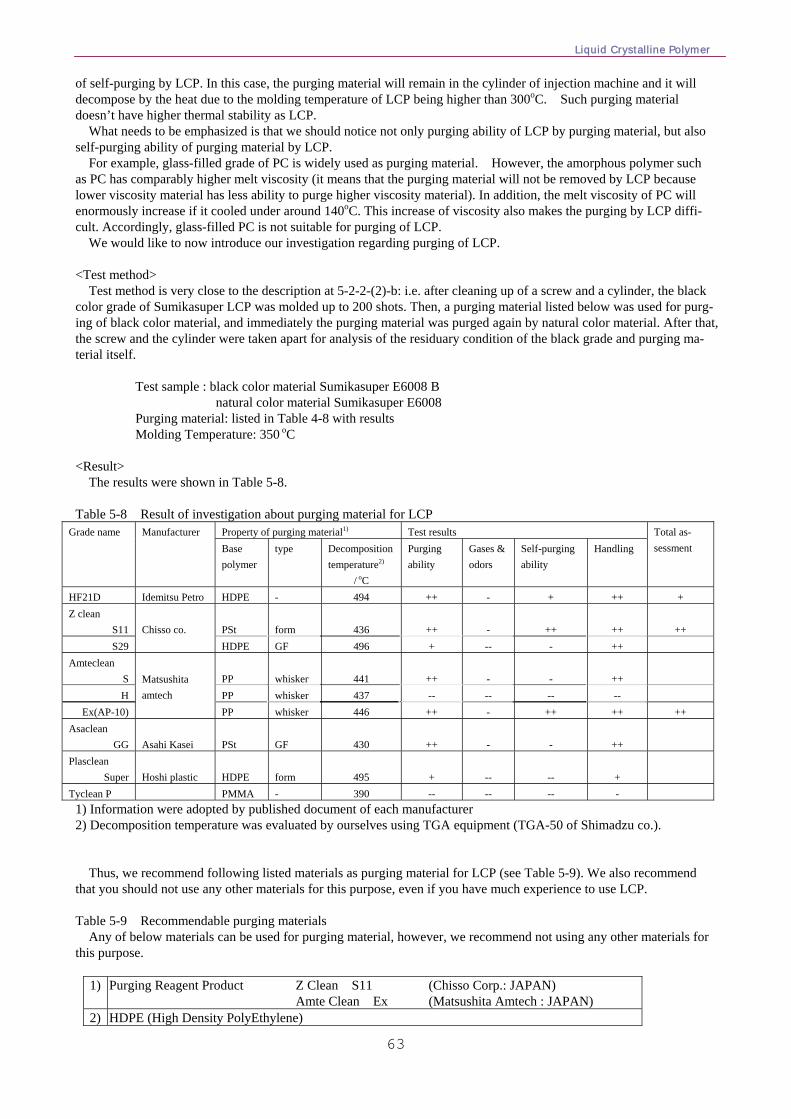
Liquid Crystalline Polymer
63
of self-purging by LCP. In this case, the purging material will remain in the cylinder of injection machine and it will decompose by the heat due to the molding temperature of LCP being higher than 300oC. Such purging material doesn’t have higher thermal stability as LCP.
What needs to be emphasized is that we should notice not only purging ability of LCP by purging material, but also self-purging ability of purging material by LCP.
For example, glass-filled grade of PC is widely used as purging material. However, the amorphous polymer such as PC has comparably higher melt viscosity (it means that the purging material will not be removed by LCP because lower viscosity material has less ability to purge higher viscosity material). In addition, the melt viscosity of PC will enormously increase if it cooled under around 140oC. This increase of viscosity also makes the purging by LCP diffi-cult. Accordingly, glass-filled PC is not suitable for purging of LCP.
We would like to now introduce our investigation regarding purging of LCP.
<Test method> Test method is very close to the description at 5-2-2-(2)-b: i.e. after cleaning up of a screw and a cylinder, the black color grade of Sumikasuper LCP was molded up to 200 shots. Then, a purging material listed below was used for purg-ing of black color material, and immediately the purging material was purged again by natural color material. After that, the screw and the cylinder were taken apart for analysis of the residuary condition of the black grade and purging ma-terial itself.
Test sample : black color material Sumikasuper E6008 B natural color material Sumikasuper E6008 Purging material: listed in Table 4-8 with results Molding Temperature: 350 oC
<Result>
The results were shown in Table 5-8. Table 5-8 Result of investigation about purging material for LCP
Property of purging material1) Test results Grade name Manufacturer Base polymer
type Decomposition temperature2)
/ oC
Purging ability
Gases & odors
Self-purging ability
Handling Total as-sessment
HF21D Idemitsu Petro HDPE - 494 ++ - + ++ + Z clean
S11 PSt
form
436
++
-
++
++
++
S29
Chisso co.
HDPE GF 496 + -- - ++ Amteclean
S PP
whisker
441
++
-
-
++
H PP whisker 437 -- -- -- -- Ex(AP-10)
Matsushita amtech
PP whisker 446 ++ - ++ ++ ++ Asaclean
GG Asahi Kasei
PSt
GF
430
++
-
-
++
Plasclean Super
Hoshi plastic
HDPE
form
495
+
--
--
+
Tyclean P PMMA - 390 -- -- -- - 1) Information were adopted by published document of each manufacturer 2) Decomposition temperature was evaluated by ourselves using TGA equipment (TGA-50 of Shimadzu co.).
Thus, we recommend following listed materials as purging material for LCP (see Table 5-9). We also recommend that you should not use any other materials for this purpose, even if you have much experience to use LCP.
Table 5-9 Recommendable purging materials
Any of below materials can be used for purging material, however, we recommend not using any other materials for this purpose.
1) Purging Reagent Product Z Clean S11 (Chisso Corp.: JAPAN)
Amte Clean Ex (Matsushita Amtech : JAPAN) 2) HDPE (High Density PolyEthylene)
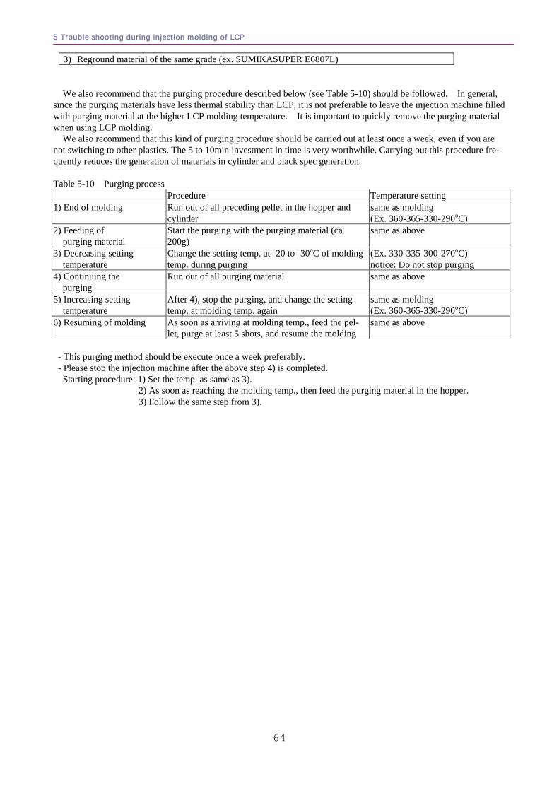
5 Trouble shooting during injection molding of LCP
64
3) Reground material of the same grade (ex. SUMIKASUPER E6807L)
We also recommend that the purging procedure described below (see Table 5-10) should be followed. In general, since the purging materials have less thermal stability than LCP, it is not preferable to leave the injection machine filled with purging material at the higher LCP molding temperature. It is important to quickly remove the purging material when using LCP molding.
We also recommend that this kind of purging procedure should be carried out at least once a week, even if you are not switching to other plastics. The 5 to 10min investment in time is very worthwhile. Carrying out this procedure fre-quently reduces the generation of materials in cylinder and black spec generation. Table 5-10 Purging process Procedure Temperature setting 1) End of molding Run out of all preceding pellet in the hopper and
cylinder same as molding (Ex. 360-365-330-290oC)
2) Feeding of purging material
Start the purging with the purging material (ca. 200g)
same as above
3) Decreasing setting temperature
Change the setting temp. at -20 to -30oC of molding temp. during purging
(Ex. 330-335-300-270oC) notice: Do not stop purging
4) Continuing the purging
Run out of all purging material same as above
5) Increasing setting temperature
After 4), stop the purging, and change the setting temp. at molding temp. again
same as molding (Ex. 360-365-330-290oC)
6) Resuming of molding As soon as arriving at molding temp., feed the pel-let, purge at least 5 shots, and resume the molding
same as above
- This purging method should be execute once a week preferably. - Please stop the injection machine after the above step 4) is completed. Starting procedure: 1) Set the temp. as same as 3). 2) As soon as reaching the molding temp., then feed the purging material in the hopper. 3) Follow the same step from 3).
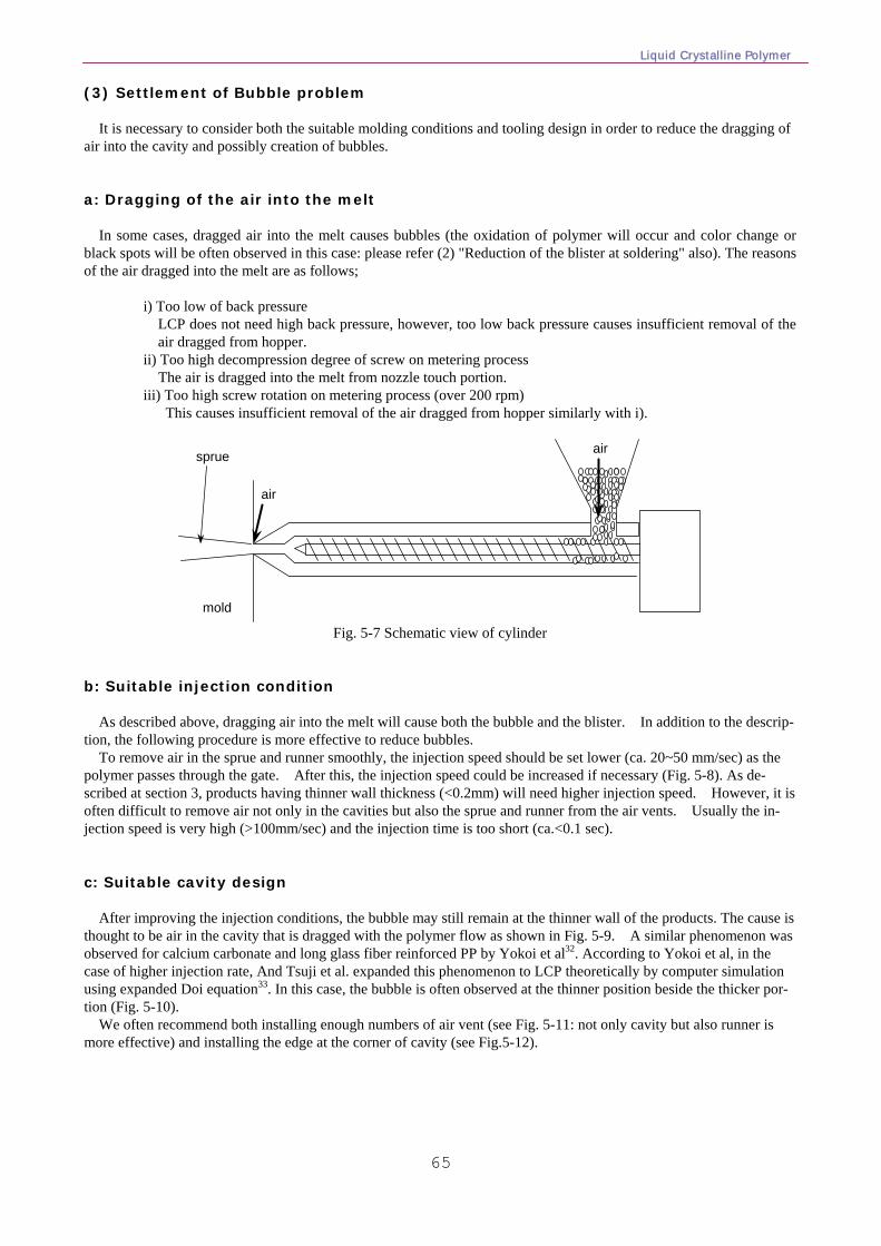
Liquid Crystalline Polymer
65
(3) Settlement of Bubble problem It is necessary to consider both the suitable molding conditions and tooling design in order to reduce the dragging of air into the cavity and possibly creation of bubbles. a: Dragging of the air into the melt In some cases, dragged air into the melt causes bubbles (the oxidation of polymer will occur and color change or black spots will be often observed in this case: please refer (2) "Reduction of the blister at soldering" also). The reasons of the air dragged into the melt are as follows; i) Too low of back pressure LCP does not need high back pressure, however, too low back pressure causes insufficient removal of the
air dragged from hopper. ii) Too high decompression degree of screw on metering process The air is dragged into the melt from nozzle touch portion. iii) Too high screw rotation on metering process (over 200 rpm) This causes insufficient removal of the air dragged from hopper similarly with i).
mold
sprue air
air
Fig. 5-7 Schematic view of cylinder
b: Suitable injection condition As described above, dragging air into the melt will cause both the bubble and the blister. In addition to the descrip-tion, the following procedure is more effective to reduce bubbles. To remove air in the sprue and runner smoothly, the injection speed should be set lower (ca. 20~50 mm/sec) as the polymer passes through the gate. After this, the injection speed could be increased if necessary (Fig. 5-8). As de-scribed at section 3, products having thinner wall thickness (<0.2mm) will need higher injection speed. However, it is often difficult to remove air not only in the cavities but also the sprue and runner from the air vents. Usually the in-jection speed is very high (>100mm/sec) and the injection time is too short (ca.<0.1 sec). c: Suitable cavity design After improving the injection conditions, the bubble may still remain at the thinner wall of the products. The cause is thought to be air in the cavity that is dragged with the polymer flow as shown in Fig. 5-9. A similar phenomenon was observed for calcium carbonate and long glass fiber reinforced PP by Yokoi et al32. According to Yokoi et al, in the case of higher injection rate, And Tsuji et al. expanded this phenomenon to LCP theoretically by computer simulation using expanded Doi equation33. In this case, the bubble is often observed at the thinner position beside the thicker por-tion (Fig. 5-10). We often recommend both installing enough numbers of air vent (see Fig. 5-11: not only cavity but also runner is more effective) and installing the edge at the corner of cavity (see Fig.5-12).
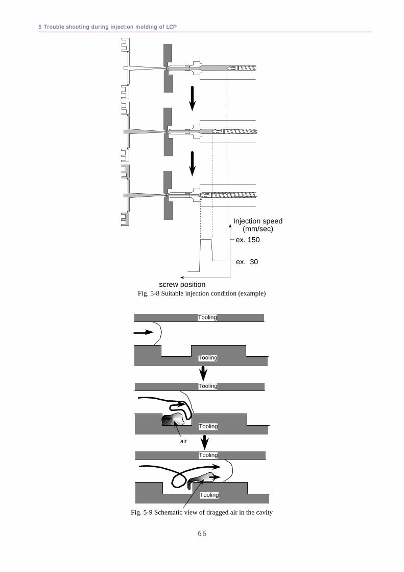
5 Trouble shooting during injection molding of LCP
66
Injection speed(mm/sec)
screw position
ex. 150
ex. 30
Fig. 5-8 Suitable injection condition (example)
Tooling
Tooling
Tooling
Tooling
Tooling
Tooling
air
Fig. 5-9 Schematic view of dragged air in the cavity
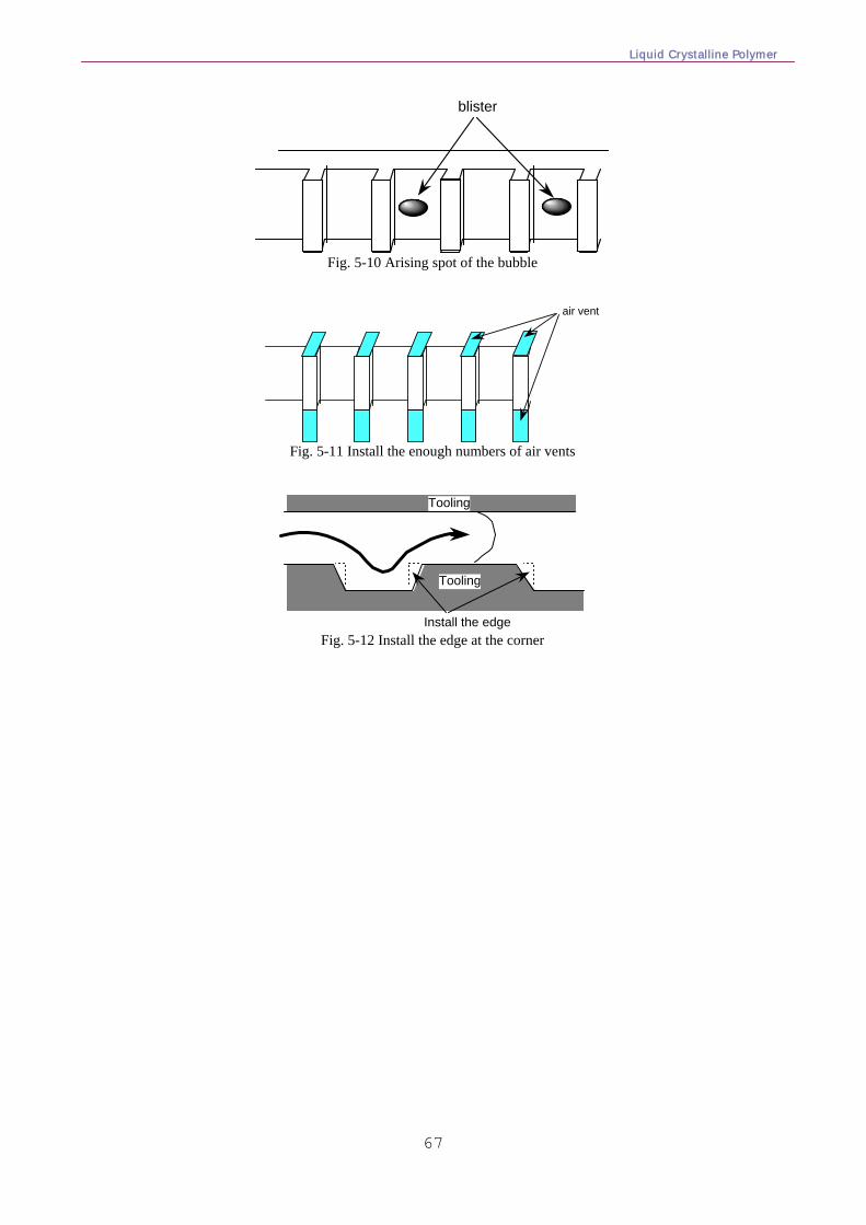
Liquid Crystalline Polymer
67
blister
Fig. 5-10 Arising spot of the bubble
air vent
Fig. 5-11 Install the enough numbers of air vents
Install the edge
Tooling
Tooling
Fig. 5-12 Install the edge at the corner
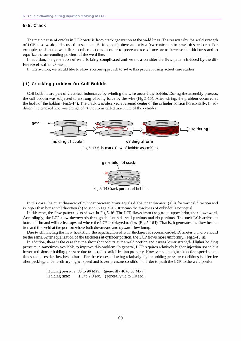
5 Trouble shooting during injection molding of LCP
68
5-5. Crack
The main cause of cracks in LCP parts is from crack generation at the weld lines. The reason why the weld strength of LCP is so weak is discussed in section 1-5. In general, there are only a few choices to improve this problem. For example, to shift the weld line to other sections in order to prevent excess force, or to increase the thickness and to equalize the surrounding portions of the weld line.
In addition, the generation of weld is fairly complicated and we must consider the flow pattern induced by the dif-ference of wall thickness.
In this section, we would like to show you our approach to solve this problem using actual case studies.
(1) Cracking problem for Coil Bobbin Coil bobbins are part of electrical inductance by winding the wire around the bobbin. During the assembly process,
the coil bobbin was subjected to a strong winding force by the wire (Fig.5-13). After wiring, the problem occurred at the body of the bobbin (Fig.5-14). The crack was observed at around center of the cylinder portion horizontally. In ad-dition, the cracked line was elongated at the rib installed inner side of the cylinder.
gate
molding of bobbin winding of wire
solderinggate
molding of bobbin winding of wire
soldering
Fig.5-13 Schematic flow of bobbin assembling
generation of crackgeneration of crack
Fig.5-14 Crack portion of bobbin
In this case, the outer diameter of cylinder between brims equals d, the inner diameter (a) is for vertical direction and is larger than horizontal direction (b) as seen in Fig. 5-15. It means the thickness of cylinder is not equal.
In this case, the flow pattern is as shown in Fig.5-16. The LCP flows from the gate to upper brim, then downward. Accordingly, the LCP flow downwards through thicker side-wall portions and rib portions. The melt LCP arrives at bottom brim and will reflect upward where the LCP is delayed to flow (Fig.5-16 i). That is, it generates the flow hesita-tion and the weld at the portion where both downward and upward flow bump.
Due to eliminating the flow hesitation, the equalization of wall-thickness is recommended. Diameter a and b should be the same. After equalization of the thickness at cylinder portion, the LCP flows more uniformly. (Fig.5-16 ii).
In addition, there is the case that the short shot occurs at the weld portion and causes lower strength. Higher holding pressure is sometimes available to improve this problem. In general, LCP requires relatively higher injection speed but lower and shorter holding pressure due to its quick solidification property. However such higher injection speed some-times enhances the flow hesitation. For these cases, allowing relatively higher holding pressure conditions is effective after packing, under ordinary higher speed and lower pressure condition in order to push the LCP to the weld portion:
Holding pressure: 80 to 90 MPa (generally 40 to 50 MPa) Holding time: 1.5 to 2.0 sec. (generally up to 1.0 sec.)
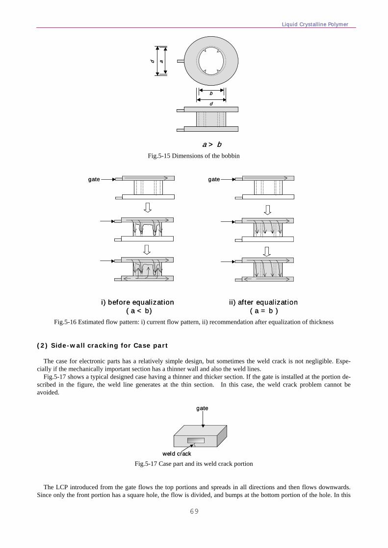
Liquid Crystalline Polymer
69
d
d a
b
a > b
d
d a
b
a > b
Fig.5-15 Dimensions of the bobbin
gate gate
i) before equalization( a < b)
ii) after equalization( a = b )
gate gate
i) before equalization( a < b)
ii) after equalization( a = b )
Fig.5-16 Estimated flow pattern: i) current flow pattern, ii) recommendation after equalization of thickness
(2) Side-wall cracking for Case part
The case for electronic parts has a relatively simple design, but sometimes the weld crack is not negligible. Espe-cially if the mechanically important section has a thinner wall and also the weld lines.
Fig.5-17 shows a typical designed case having a thinner and thicker section. If the gate is installed at the portion de-scribed in the figure, the weld line generates at the thin section. In this case, the weld crack problem cannot be avoided.
gate
weld crack
gate
weld crack Fig.5-17 Case part and its weld crack portion
The LCP introduced from the gate flows the top portions and spreads in all directions and then flows downwards. Since only the front portion has a square hole, the flow is divided, and bumps at the bottom portion of the hole. In this
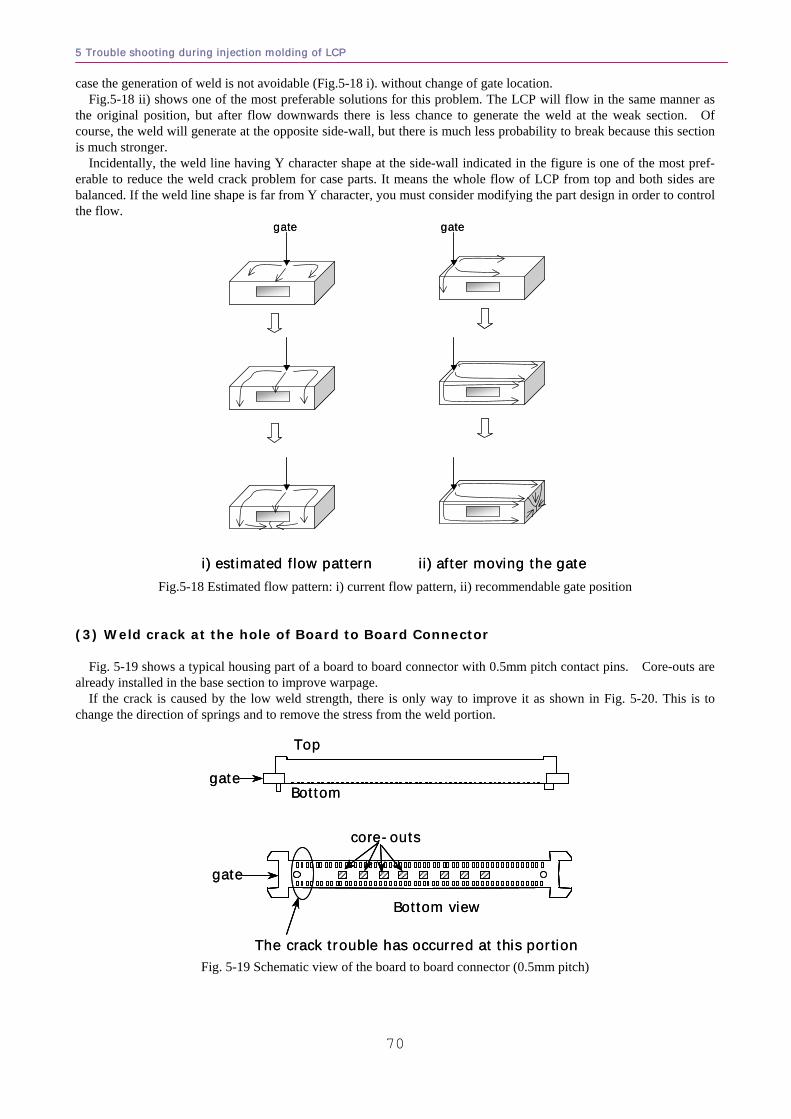
5 Trouble shooting during injection molding of LCP
70
case the generation of weld is not avoidable (Fig.5-18 i). without change of gate location. Fig.5-18 ii) shows one of the most preferable solutions for this problem. The LCP will flow in the same manner as
the original position, but after flow downwards there is less chance to generate the weld at the weak section. Of course, the weld will generate at the opposite side-wall, but there is much less probability to break because this section is much stronger.
Incidentally, the weld line having Y character shape at the side-wall indicated in the figure is one of the most pref-erable to reduce the weld crack problem for case parts. It means the whole flow of LCP from top and both sides are balanced. If the weld line shape is far from Y character, you must consider modifying the part design in order to control the flow.
gate gate
i) estimated flow pattern ii) after moving the gate
gate gate
i) estimated flow pattern ii) after moving the gate
Fig.5-18 Estimated flow pattern: i) current flow pattern, ii) recommendable gate position (3) Weld crack at the hole of Board to Board Connector Fig. 5-19 shows a typical housing part of a board to board connector with 0.5mm pitch contact pins. Core-outs are already installed in the base section to improve warpage. If the crack is caused by the low weld strength, there is only way to improve it as shown in Fig. 5-20. This is to change the direction of springs and to remove the stress from the weld portion.
Bottom view
gate
core-outs
Bottom
Top
gate
The crack trouble has occurred at this portion
Bottom view
gate
core-outs
Bottom
Top
gate
The crack trouble has occurred at this portion Fig. 5-19 Schematic view of the board to board connector (0.5mm pitch)
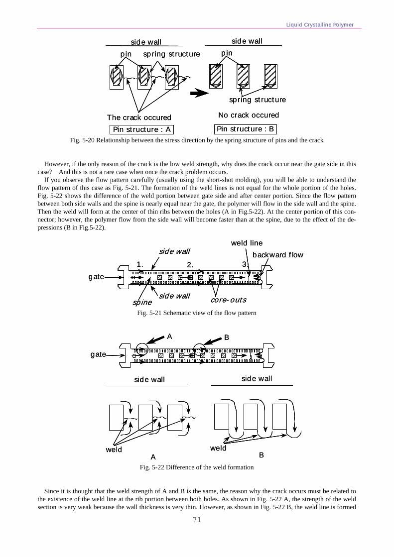
Liquid Crystalline Polymer
71
The crack occured
side wall side wallpin spring structure
No crack occured
Pin structure : A Pin structure : B
pin
spring structure
The crack occured
side wall side wallpin spring structure
No crack occured
Pin structure : A Pin structure : B
pin
spring structure
Fig. 5-20 Relationship between the stress direction by the spring structure of pins and the crack
However, if the only reason of the crack is the low weld strength, why does the crack occur near the gate side in this case? And this is not a rare case when once the crack problem occurs. If you observe the flow pattern carefully (usually using the short-shot molding), you will be able to understand the flow pattern of this case as Fig. 5-21. The formation of the weld lines is not equal for the whole portion of the holes. Fig. 5-22 shows the difference of the weld portion between gate side and after center portion. Since the flow pattern between both side walls and the spine is nearly equal near the gate, the polymer will flow in the side wall and the spine. Then the weld will form at the center of thin ribs between the holes (A in Fig.5-22). At the center portion of this con-nector; however, the polymer flow from the side wall will become faster than at the spine, due to the effect of the de-pressions (B in Fig.5-22).
gate1. 2. 3.
weld linebackward flowside wall
side wallspine core-outs
gate1. 2. 3.
weld linebackward flowside wall
side wallspine core-outs
Fig. 5-21 Schematic view of the flow pattern
gate
A B
A Bweld weld
side wall side wall
gate
A B
A Bweld weld
side wall side wall
Fig. 5-22 Difference of the weld formation
Since it is thought that the weld strength of A and B is the same, the reason why the crack occurs must be related to the existence of the weld line at the rib portion between both holes. As shown in Fig. 5-22 A, the strength of the weld section is very weak because the wall thickness is very thin. However, as shown in Fig. 5-22 B, the weld line is formed
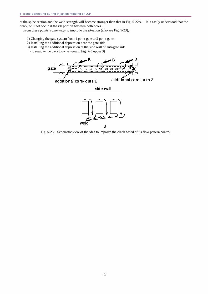
5 Trouble shooting during injection molding of LCP
72
at the spine section and the weld strength will become stronger than that in Fig. 5-22A. It is easily understood that the crack, will not occur at the rib portion between both holes. From these points, some ways to improve the situation (also see Fig. 5-23); 1) Changing the gate system from 1 point gate to 2 point gates 2) Installing the additional depression near the gate side 3) Installing the additional depression at the side wall of anti-gate side (to remove the back flow as seen in Fig. 7-3 upper 3)
gate
additional core-outs 1 additional core-outs 2
B
Bweld
side wall
B B
gate
additional core-outs 1 additional core-outs 2
BB
Bweld
side wall
Bweld
side wall
BB BB
Fig. 5-23 Schematic view of the idea to improve the crack based of its flow pattern control
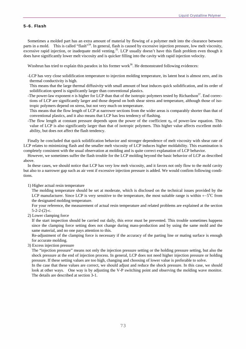
Liquid Crystalline Polymer
73
5-6. Flash
Sometimes a molded part has an extra amount of material by flowing of a polymer melt into the clearance between parts in a mold. This is called “flash”34. In general, flash is caused by excessive injection pressure, low melt viscosity, excessive rapid injection, or inadequate mold venting.35. LCP usually doesn’t have this flash problem even though it does have significantly lower melt viscosity and is quicker filling into the cavity with rapid injection velocity.
Wissbrun has tried to explain this paradox in his former work36. He demonstrated following evidences: -LCP has very close solidification temperature to injection molding temperature, its latent heat is almost zero, and its thermal conductivity is high.
This means that the large thermal diffusivity with small amount of heat induces quick solidification, and its order of solidification speed is significantly larger than conventional plastics.
-The power-law exponent n is higher for LCP than that of the isotropic polymers tested by Richardson37. End correc-tions of LCP are significantly larger and those depend on both shear stress and temperature, although those of iso-tropic polymers depend on stress, but not very much on temperature.
This means that the flow length of LCP at narrower sections from the wider areas is comparably shorter than that of conventional plastics, and it also means that LCP has less tendency of flashing.
-The flow length at constant pressure depends upon the power of the coefficient η0 of power-law equation. This value of LCP is also significantly larger than that of isotropic polymers. This higher value affects excellent mold-ability, but does not affect the flash tendency.
Finally he concluded that quick solidification behavior and stronger dependence of melt viscosity with shear rate of
LCP relates to minimizing flash and the smaller melt viscosity of LCP induces higher moldability. This examination is completely consistent with the usual observation at molding and is quite correct explanation of LCP behavior.
However, we sometimes suffer the flash trouble for the LCP molding beyond the basic behavior of LCP as described above.
In these cases, we should notice that LCP has very low melt viscosity, and it favors not only flow to the mold cavity but also to a narrower gap such as air vent if excessive injection pressure is added. We would confirm following condi-tions.
1) Higher actual resin temperature The molding temperature should be set at moderate, which is disclosed on the technical issues provided by the
LCP manufacturer. Since LCP is very sensitive to the temperature, the most suitable range is within +−5oC from the designated molding temperature.
For your reference, the measurement of actual resin temperature and related problems are explained at the section 5-2-2-(2)-c.
2) Lower clamping force If the start inspection should be carried out daily, this error must be prevented. This trouble sometimes happens
since the clamping force setting does not change during mass-production and by using the same mold and the same material, and no one pays attention to this.
Re-adjustment of the clamping force is necessary if the accuracy of the parting line or mating surface is enough for accurate molding.
3) Excess injection pressure The “injection pressure” means not only the injection pressure setting or the holding pressure setting, but also the
shock pressure at the end of injection process. In general, LCP does not need higher injection pressure or holding pressure. If these setting values are too high, changing and choosing of lower value is preferable to solve. In the case that these values are correct, we should adjust and reduce the shock pressure. In this case, we should look at other ways. One way is by adjusting the V-P switching point and observing the molding wave monitor. The details are described at section 3-1.
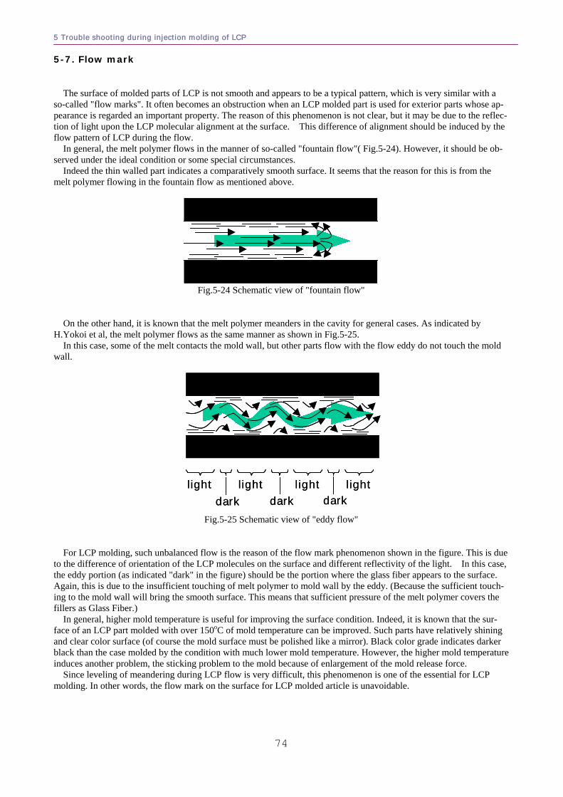
5 Trouble shooting during injection molding of LCP
74
5-7. Flow mark
The surface of molded parts of LCP is not smooth and appears to be a typical pattern, which is very similar with a so-called "flow marks". It often becomes an obstruction when an LCP molded part is used for exterior parts whose ap-pearance is regarded an important property. The reason of this phenomenon is not clear, but it may be due to the reflec-tion of light upon the LCP molecular alignment at the surface. This difference of alignment should be induced by the flow pattern of LCP during the flow.
In general, the melt polymer flows in the manner of so-called "fountain flow"( Fig.5-24). However, it should be ob-served under the ideal condition or some special circumstances.
Indeed the thin walled part indicates a comparatively smooth surface. It seems that the reason for this is from the melt polymer flowing in the fountain flow as mentioned above.
Fig.5-24 Schematic view of "fountain flow"
On the other hand, it is known that the melt polymer meanders in the cavity for general cases. As indicated by H.Yokoi et al, the melt polymer flows as the same manner as shown in Fig.5-25.
In this case, some of the melt contacts the mold wall, but other parts flow with the flow eddy do not touch the mold wall.
lightdark
lightdark
lightdark
lightlightdark
lightdark
lightdark
light
Fig.5-25 Schematic view of "eddy flow"
For LCP molding, such unbalanced flow is the reason of the flow mark phenomenon shown in the figure. This is due to the difference of orientation of the LCP molecules on the surface and different reflectivity of the light. In this case, the eddy portion (as indicated "dark" in the figure) should be the portion where the glass fiber appears to the surface. Again, this is due to the insufficient touching of melt polymer to mold wall by the eddy. (Because the sufficient touch-ing to the mold wall will bring the smooth surface. This means that sufficient pressure of the melt polymer covers the fillers as Glass Fiber.)
In general, higher mold temperature is useful for improving the surface condition. Indeed, it is known that the sur-face of an LCP part molded with over 150oC of mold temperature can be improved. Such parts have relatively shining and clear color surface (of course the mold surface must be polished like a mirror). Black color grade indicates darker black than the case molded by the condition with much lower mold temperature. However, the higher mold temperature induces another problem, the sticking problem to the mold because of enlargement of the mold release force.
Since leveling of meandering during LCP flow is very difficult, this phenomenon is one of the essential for LCP molding. In other words, the flow mark on the surface for LCP molded article is unavoidable.
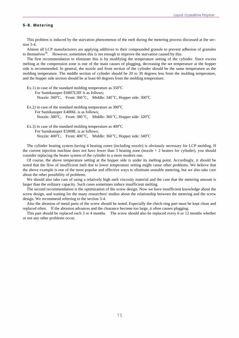
Liquid Crystalline Polymer
75
5-8. Metering
This problem is induced by the starvation phenomenon of the melt during the metering process discussed at the sec-tion 3-4.
Almost all LCP manufacturers are applying additives to their compounded granule to prevent adhesion of granules to themselves38. However, sometimes this is not enough to improve the starvation caused by this.
The first recommendation to eliminate this is by modifying the temperature setting of the cylinder. Since excess melting at the compression zone is one of the main causes of plugging, decreasing the set temperature at the hopper side is recommended. In general, the nozzle and front section of the cylinder should be the same temperature as the molding temperature. The middle section of cylinder should be 20 to 30 degrees less from the molding temperature, and the hopper side section should be at least 60 degrees from the molding temperature.
Ex.1) in case of the standard molding temperature as 350oC
For Sumikasuper E6807LHF is as follows; Nozzle: 360oC, Front: 360 oC, Middle: 340 oC, Hopper side: 300oC Ex.2) in case of the standard molding temperature as 380oC
For Sumikasuper E4006L is as follows; Nozzle: 380oC, Front: 380 oC, Middle: 360 oC, Hopper side: 320oC Ex.3) in case of the standard molding temperature as 400oC
For Sumikasuper E5008L is as follows; Nozzle: 400oC, Front: 400 oC, Middle: 360 oC, Hopper side: 340oC The cylinder heating system having 4 heating zones (including nozzle) is obviously necessary for LCP molding. If
the current injection machine does not have fewer than 3 heating zone (nozzle + 2 heaters for cylinder), you should consider replacing the heater system of the cylinder to a more modern one.
Of course, the above temperature setting at the hopper side is under its melting point. Accordingly, it should be noted that the flow of insufficient melt due to lower temperature setting might cause other problems. We believe that the above example is one of the most popular and effective ways to eliminate unstable metering, but we also take care about the other possibility of problems.
We should also take care of using a relatively high melt viscosity material and the case that the metering amount is larger than the ordinary capacity. Such cases sometimes induce insufficient melting.
The second recommendation is the optimization of the screw design. Now we have insufficient knowledge about the screw design, and waiting for the many researchers' studies about the relationship between the metering and the screw design. We recommend referring to the section 3-4.
Also the abrasion of metal parts of the screw should be noted. Especially the check-ring part must be kept clean and replaced often. If the abrasion advances and the clearance become too large, it often causes plugging.
This part should be replaced each 3 or 4 months. The screw should also be replaced every 6 or 12 months whether or not any other problems occur.
5 Trouble shooting during injection molding of LCP
76
5-9. Short-shot
Most people misunderstand the actual reason of short-shot problem during LCP molding. Usually the molding engi-neer thinks that the reasons of short-shot involves the flowability or melt viscosity of the material. It is only one of the reasons; the cause is really due to 4 reasons as shown in the Fig.5-26.
First, it is a higher melt viscosity, which is the most conventional thinking way. Second, it is due to the flow hesitation as described at section 3-3. It is very troublesome because it is difficult to dis-
tinguish between shortage of fluidity or generation of flow hesitation for non-expert engineers of LCP molding. The appearances of both reasons are very similar, however, the remedy is different. In the case of shortage by fluidity, optimization of the molding conditions will usually work. In the case of flow hesitation, it will not be soluble by the same way.
The third reason is due to the starvation derived by the plugging described in the section 5-8. The last reason is due to dragged air. Installing the air vent is one of powerful solution if the cause is insufficient
exhaust of cavity air. We must consider about each reason and improvement.
Short-shot
flow hesitation
starvation
dragging of air
insufficiency of flowability higher viscosity
unbalance of flow (section 3-3)
plugging (section 3-4)
bad exhaust (section 4-4(3))
<cause>Short-shot
flow hesitation
starvation
dragging of air
insufficiency of flowability higher viscosity
unbalance of flow (section 3-3)
plugging (section 3-4)
bad exhaust (section 4-4(3))
<cause>
Fig.5-26 Classification of short-shot problem
1) Insufficiency of flowability In this case, molding temperature should be increased slightly. We usually recommend increasing 5 to 10 oC from
the original setting at the nozzle and H1 (Front portion heater of cylinder). You must take care about the generation of Flash because excessive increase will produce unexpected decrease of the melt viscosity of the material.
At the same time, slight increase of the injection speed and holding pressure are also effective. For injection speed, it must be increased more than 100mm/sec if it is lower than such magnitude. In the case of over
100mm/sec, every 10mm/sec increase is recommended. For holding pressure condition, elongation of holding time up to 2.0 sec is recommended. Since the solidification of
LCP is so quick, over 2.0 sec of holding time usually has no effect. The gate will seal by solidification of LCP prior to 2.0 sec.
All procedures of this section must be done slowly because sudden changes of those parameters induce a Flash prob-lem and it will link to break the mold part.
If no change is observed, you should consider the following reasons and procedures. 2) Flow hesitation Sometimes this problem involves Crack (weld-crack) problem. You should also refer the explanation of "flow hesi-
tation (section 3-3)" and "crack (section 5-5)" within this section. It should be done carefully as flow hesitation may occur even if the thickness difference is 0.01mm for relatively
thinner parts having average thickness under 0.3mm. If you observe the cavity dependence or the case that the problem generated fixed portion, you should reconfirm the distribution of cavity dimension during assembling of the mold, the dimension change of the gate due to abrasion or runner length difference from sprue.
Let us explain this kind of short-shot and its solution by using an example. Fig.5-27 shows a bobbin item for induction coil. This item had not only a short-shot problem (generation of hole),
but also a weld crack problem. The molding engineer asked us the most suitable molding condition because changing the molding temperature or increasing the injection speed did not improve these problems.
The reason for these problems was thought to be that the flow of LCP from the gate filled the upper rim first
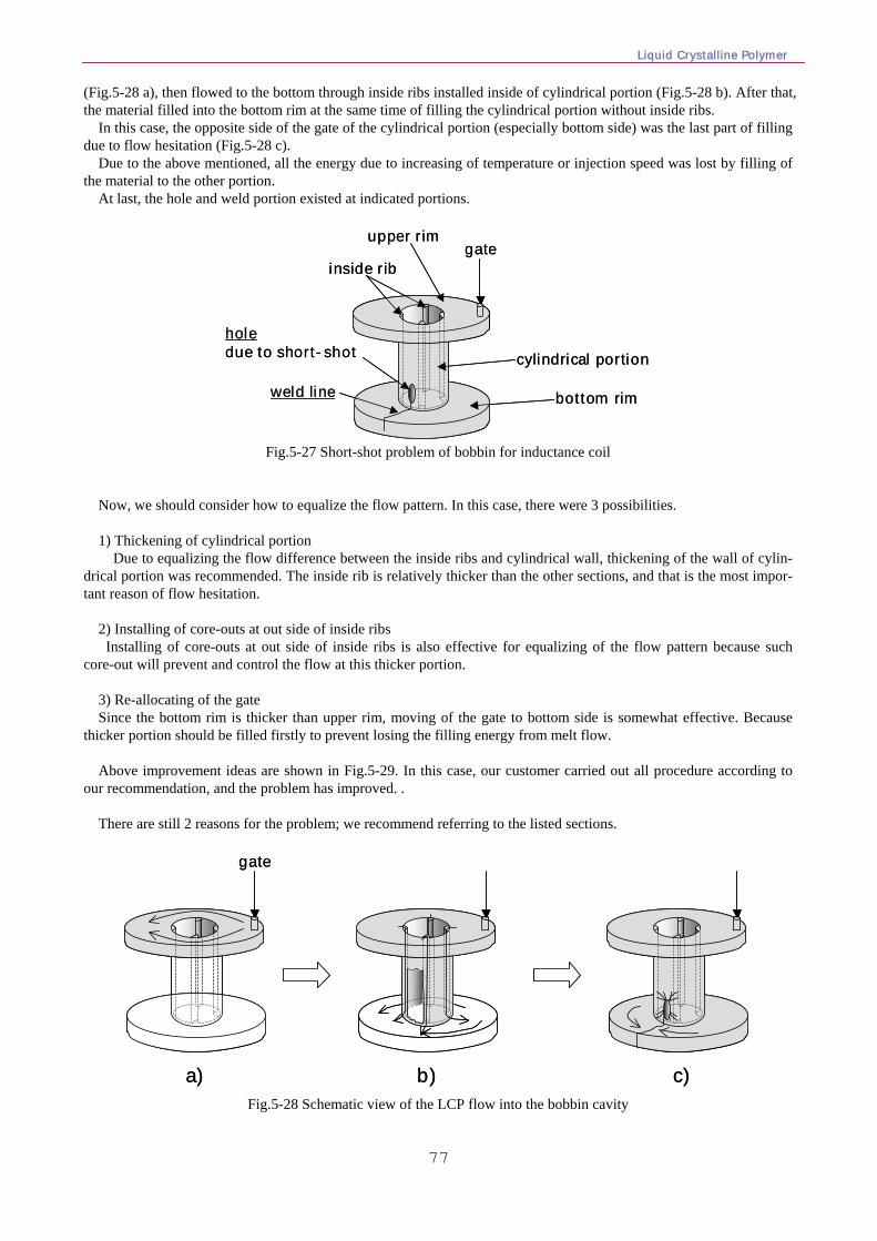
Liquid Crystalline Polymer
77
(Fig.5-28 a), then flowed to the bottom through inside ribs installed inside of cylindrical portion (Fig.5-28 b). After that, the material filled into the bottom rim at the same time of filling the cylindrical portion without inside ribs.
In this case, the opposite side of the gate of the cylindrical portion (especially bottom side) was the last part of filling due to flow hesitation (Fig.5-28 c).
Due to the above mentioned, all the energy due to increasing of temperature or injection speed was lost by filling of the material to the other portion.
At last, the hole and weld portion existed at indicated portions.
holeholedue to short-shot
weld lineweld line
gateinside rib
cylindrical portion
upper rim
bottom rim
holeholedue to short-shot
weld lineweld line
gateinside rib
cylindrical portion
upper rim
bottom rim
Fig.5-27 Short-shot problem of bobbin for inductance coil
Now, we should consider how to equalize the flow pattern. In this case, there were 3 possibilities. 1) Thickening of cylindrical portion Due to equalizing the flow difference between the inside ribs and cylindrical wall, thickening of the wall of cylin-
drical portion was recommended. The inside rib is relatively thicker than the other sections, and that is the most impor-tant reason of flow hesitation.
2) Installing of core-outs at out side of inside ribs Installing of core-outs at out side of inside ribs is also effective for equalizing of the flow pattern because such
core-out will prevent and control the flow at this thicker portion. 3) Re-allocating of the gate Since the bottom rim is thicker than upper rim, moving of the gate to bottom side is somewhat effective. Because
thicker portion should be filled firstly to prevent losing the filling energy from melt flow. Above improvement ideas are shown in Fig.5-29. In this case, our customer carried out all procedure according to
our recommendation, and the problem has improved. . There are still 2 reasons for the problem; we recommend referring to the listed sections.
gate
a) b) c)
gate
a) b) c)
Fig.5-28 Schematic view of the LCP flow into the bobbin cavity
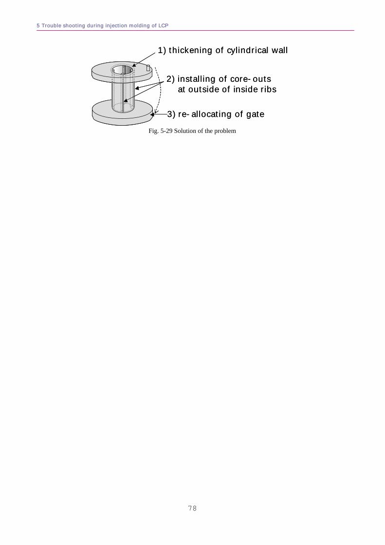
5 Trouble shooting during injection molding of LCP
78
1) thickening of cylindrical wall
2) installing of core-outs at outside of inside ribs
3) re-allocating of gate
1) thickening of cylindrical wall
2) installing of core-outs at outside of inside ribs
3) re-allocating of gate
Fig. 5-29 Solution of the problem
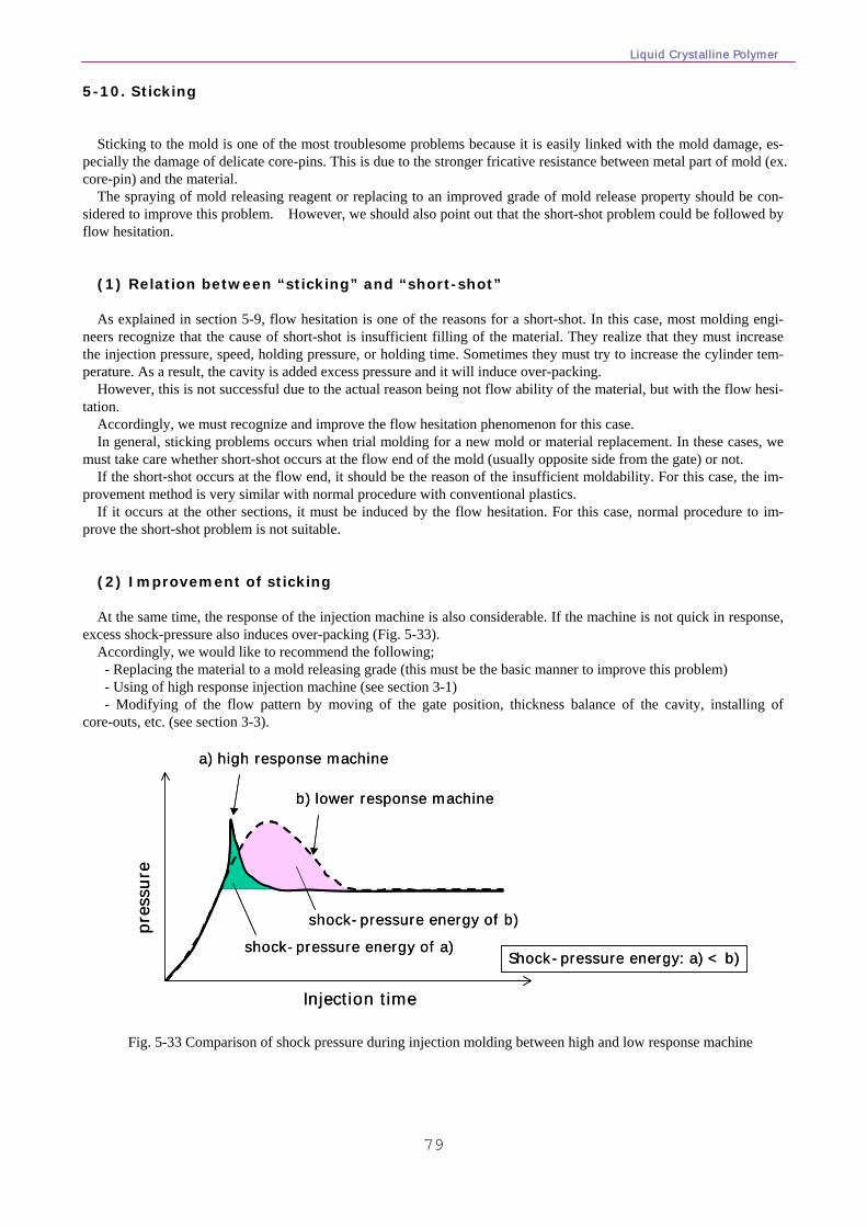
Liquid Crystalline Polymer
79
5-10. Sticking
Sticking to the mold is one of the most troublesome problems because it is easily linked with the mold damage, es-pecially the damage of delicate core-pins. This is due to the stronger fricative resistance between metal part of mold (ex. core-pin) and the material.
The spraying of mold releasing reagent or replacing to an improved grade of mold release property should be con-sidered to improve this problem. However, we should also point out that the short-shot problem could be followed by flow hesitation.
(1) Relation between “sticking” and “short-shot” As explained in section 5-9, flow hesitation is one of the reasons for a short-shot. In this case, most molding engi-
neers recognize that the cause of short-shot is insufficient filling of the material. They realize that they must increase the injection pressure, speed, holding pressure, or holding time. Sometimes they must try to increase the cylinder tem-perature. As a result, the cavity is added excess pressure and it will induce over-packing.
However, this is not successful due to the actual reason being not flow ability of the material, but with the flow hesi-tation.
Accordingly, we must recognize and improve the flow hesitation phenomenon for this case. In general, sticking problems occurs when trial molding for a new mold or material replacement. In these cases, we
must take care whether short-shot occurs at the flow end of the mold (usually opposite side from the gate) or not. If the short-shot occurs at the flow end, it should be the reason of the insufficient moldability. For this case, the im-
provement method is very similar with normal procedure with conventional plastics. If it occurs at the other sections, it must be induced by the flow hesitation. For this case, normal procedure to im-
prove the short-shot problem is not suitable. (2) Improvement of sticking At the same time, the response of the injection machine is also considerable. If the machine is not quick in response,
excess shock-pressure also induces over-packing (Fig. 5-33). Accordingly, we would like to recommend the following; - Replacing the material to a mold releasing grade (this must be the basic manner to improve this problem) - Using of high response injection machine (see section 3-1) - Modifying of the flow pattern by moving of the gate position, thickness balance of the cavity, installing of
core-outs, etc. (see section 3-3).
Injection time
pres
sure
a) high response machine
b) lower response machine
shock-pressure energy of a)
shock-pressure energy of b)
Shock-pressure energy: a) < b)
Injection time
pres
sure
a) high response machine
b) lower response machine
shock-pressure energy of a)
shock-pressure energy of b)
Shock-pressure energy: a) < b)
Fig. 5-33 Comparison of shock pressure during injection molding between high and low response machine
5 Trouble shooting during injection molding of LCP
80
5-11. Warpage As discussed in section 4, the main reason of warpage for LCP molding is the flow pattern, which brings the high orientation of LCP molecule to the flow direction.
Since LCP does not indicate Tg (glass transition temperature), the mold temperature will not influence warpage and also the dimensions. In addition, injection conditions such as cylinder temperature, injection speed & pressure or holding pressure will also not influence warpage.
In other words, the warpage of LCP molding is not changeable by molding conditions. If the warpage problem occurs, we should investigate whether the flow pattern is appropriate or not. If the problem suddenly occurs, we should also investigate whether there is a possibility of changing the flow pattern.
For designing an appropriate flow pattern, we have already discussed in section 4. In this section, we would like to discuss the case where the warpage trouble suddenly occurs during production – the initial warpage was improved before starting production.
Since the warpage is only influenced by flow pattern, we consider the reason why the flow pattern changes. The reasons are considered as follows; a. Viscosity change of material Each lot No. material has a melt viscosity. Usually, such viscosity difference is controlled within a certain range,
which is well considered by the material company. However, if the specific lot No. material indicates different result of viscosity; we recommend asking to mate-
rial company for help. On the other hand, there is a possibility that the material viscosity changes at the customer side. The main reasons are contamination of other material and insufficient drying before molding. Both reasons and improvements are discussed in section 5-4. Blister & Bubble. Please refer the section. b. Abrasion of mold part Dimension change should also be considered. We often observed that only 0.01mm difference of dimension
significantly changes the flow pattern. This is especially so if the dimension change occurred at the thickness of main flow portion. .
This case should be considered when the mold is maintained or additional mold is constructed. In this case, such small difference of dimension often brings different results of warpage.
c. Unsuitable molding condition As described above, in general molding conditions does not influence the warpage of LCP. However, if original
molding conditions were not suitable, sometimes the deviation of the injection machine will influence to the flow pattern and cause warpage.
In this meaning, the following cases are sometimes the cause of the problem; -too slow injection speed -too low cylinder temperature Both reasons prevent the formation of the orientation layer of LCP (so-called skin layer). In this case, the ani-
sotropy must be lower than the case of suitable injection condition. The most difficult case is where the initial warpage has not been improved by modifying of the mold design.
Sometimes modification of the original design of the mold must be necessary (please refer the section 4). Suitable injection molding conditions is also one of the most important responses to reduce the problems. Please refer the section 3 and use it under appropriate condition.
Liquid Crystalline Polymer
81
<references>
1 for instance: Tatsukami, Y., Asai, K., Inoue, M., Sugimoto, H., Hayatsu, K. and Kobayashi, T., Sumi-tomo Kagaku , 1987-I, 20(1987); Asai, K., Plastics, 45, 76 (1994); Nomura, H., JETI, 46, 79 (1998) 2 for instance: ed. Koide, N., "Liquid Crystalline Polymer –Synthesis, Molding and Application- " (Japanese), Sigma
pub. (1987); ed. Iimura, I., Asada, T. and Abe, A., “Liquid crystalline polymer – Its basic and application”, Sigma pub.
(1988); “Liquid crystalline polymer – committee on engineering and technological system”, Nat’l. Acad. Press (1990);
Wang, X.J. and Zhou, Q.F., “Liquid crystalline polymers”, World scientific pub. (2004); Suenaga, J., “Liquid crystal
polymer for molding and designing”, Sigma pub. (1995) 3 Lehmann, O., Z. Phys. Chem., 4, 462 (1889) 4 Reinitzer, F., Monatsh. Chem., 9, 421(1888) 5 Onsager, L., Ann. N.Y. Acad. Sci., 51, 627(1949); Ishihara, A., J. Chem. Phys., 19, 1142(1951); Flory, P.J., J. Proc.
R. Soc., A 234, 60(1956); ibid., 234, 73(1956); ibid., Selected Works., Stanford University Press, 2267(1985) 6 Maier, W. and Saupe, A.Z., Naturforsch., A 14, 882(1959); Maier, W. and Saupe, A.Z., Naturforsch.,A 15,
287(1960); Krigbaum, W.R., Brelsford, G., and Cifferi, A., Macromolecules, 22, 2487(1989); Aharoni, S.M., Macro-
molecules, 21, 1941 (1988) 7 Technical Information, , Tosoh corporation, 107 (1999) 8 Blackwell, J., Cheng, H.M. and Biswas, A., Macromolecules, 21, 39(1988); Biswas, A. and Blackwell, J., Macro-
molecules, 21, 3146(1988); ibid, 21, ibid, 3152(1988); ibid, 21, 3158(1988) 9 Shibaev, V.P., Talroze, R.V., Korobeinikova, I.A. and Platé, N.A., Liq. Cryst., 4, 467(1989) 10 Brostow, W., Polymer, 31, 979(1990); Demus, D., Mol. Cryst. Liq. Cryst., 165, 45(1988); ibid, Liq. Cryst., 5,
75(1989) 11 Weng, T., Hiltner, A. and Baer, E., J. Mater. Sci., 21, 744(1986); Ide, Y. and Ophir, Z., Polymer Eng. Sci., 23,
261(1983) 12 Nagano, S., Plastics, 45, 55 (1994) 13 Hsieh, T.T., Tiu, C. and Simon, G.P., J. Appl. Polym. Sci., 82, 2252(2001) 14 Cheng, S.Z.D., Macromolecules, 21, 2475(1988); Cheng, S.Z.D., Janimak, J.J., Zhang, A. and Zhou, Z., Macro-
molecules, 22, 4240(1989); Cheng, S.Z.D., Zhang, A., Johnson, R.L. and Wu, Z., Macromolecules, 23, 1196(1990) 15 Field, N.D., Baldwin, R., Layton, R, Frayer, P. and Scardiglia, F., Macromolecules, 21, 2155(1988); Chung, T.S.,
Cheng, M., Pallathadka, P.K. and Goh, S.H., Polym. Eng. Sci., 953, 39(1999); Wiesner, U., Laupretre, F. and Monnerie,
L., Macromolecules, 27, 3632(1994); Nam, J., Fukai, T. and Kyu, T., Macromolecules, 24, 6250(1991) 16 Blundell, D.J. and Buckingham, K.A., Polymer, 26, 1623(1985); MacDonald, W.A., Mol. Cryst. Liq. Cryst., 153,
311(1987) 17 Troughton, M.J., Unwin, A.P., Davies, G.R. and Ward, I.M., Polymer, 29, 1389(1988); Green, D.I., Orchard, A.J.,
Davies, G.R. and Ward, I.M., J. Polym. Sci. part B Polym. Phys., 28, 2225(1990) ; Ward, I.M., Makromol. Chem.,
Makromol. Symp., 69, 75(1993) 18 Jin, X. and Chung, T.S., J. Appl. Polym. Sci., 73, 2195(1999); Sueoka, K., Nagata, M., Ohtani, H., Nagai, N. and
Tsuge, S., J. Polym. Sci. part A: Polym. Chem., 29, 1903(1991) 19 S.Nagano, H.Yamauchi and M.Hirakawa, Sumitomo Chemical, (2001) 20 Naitove, M.N., Plast. Technol.,35, 31(1985)
5 Trouble shooting during injection molding of LCP
82
21 Data were adapted from following references:
PEEK: Sumitomo Chemical, Technical Note PEEK 16, 32 PPS: Mitsubishi Engineering-Plastics, general catalog G-2, 11 (1994) PES: Sumitomo Chemical, Sumikaexcel PES catalog, 4 PC: Mitsubishi Engineering-Plastics, general catalog G-2, 1 (1994) LCP: Sumitomo Chemical, Technical Note 26, 5
22 S.Nagano, JETI, 52, No.4, 72 (2004) 23 ibid 24 S.Nagano, M.Maeda and H.Nomura, SeikeiKako ’97 prepn., 333 (1997)
S.Nagano, M.Maeda and H.Nomura, JP A10-323870 25 Sumitomo Chemical private technical letter 3, (1994) 26 Nomura, H., Honda, Y, Chikaishi, K and Watanabe, Y., SeikeiKakou '91 prepn., 117 (1991) 27 for instance: Nishikida, K., et al, "Material analysis by Infra-Red spectra", Kodansha pub. (1986); Pretsch, E., Clerc,
T., Seibl, J. and Simon, W., "Tabellen zur Structuraufklaerung organischer Verbindungen mit spektroskopischen Meth-
oden", Springer pub. (1981) 28 ed. Polymer Society, "Solid structure of polymer", Kyoritsu pub. (1984) 29 Y.Murata and H.Yokoi, SeisanKenkyu, 43, No.11, 537 (1991) 30 R.T.Maher and H.T.Plant, Modern Plastics, May, 78 (1974); C.Maier, Polym. Eng. Sci., 36, 1502
(1996) 31 A. Galskoy and K.K.Wang, Plast. Eng., 34-11, 42 (1978) 32 H. Yokoi and H. Matsuda, Seikeikakou Symposia '98, 271(1998)
H. Matsuda and H. Yokoi, Seisan Kenkyu, 51, 267(1999) 33 T. Tsuji and S. Chono, Seikei-Kakou, 13, 634(2001) 34 A. Takeuchi, English for the understanding of plastic, Kogyo Chosakai, Japan, p.226, (1996) 35 D.V. Rosato and D.V. Rosato, Injection Molding Handbook, Van Nostrand Reinhold, New York
(1986); I.I. Rubin, Injection Molding Theory and Practice, p249, Wiley, New York (1972) 36 K.F.Wissbrun, Polym. Eng. Sci., 31, 1130 (1991) 37 S.M.Richardson, Rheol. Acta, 24, 509 (1985) 38 Japanese patent JP A05-125259, JP A09-143347, etc..


