
LNP™ LDS AND THERMAL CONDUCTIVE COMPOUNDED SOLUTIONS
February 2014, Andy Verheijden

LDS FOR MID

No. 2
Value proposition
LNP Thermocomp LDS compounds will help to drive productivity and design cycle
flexibility, through part consolidation and miniaturization versus conventional technologies,
such as metal stamping, potentially providing system cost out thanks to shorter value
chain and faster market introduction.
LNP™ THERMOCOMP™ LDS COMPOUNDS FOR MID
LNP Thermocomp LDS compound may provide productivity & 3D design capability
Part consolidation Design freedom

No. 3
3
VALUE PROPOSITIONS MATERIAL & PROCESS
SABIC LNP & LDS technology providing potential cost & weight savings
Key advantages of LPKF LDS process
Very flexible process, for 3D prototyping and production
Fast operating method, typical operating speed 3 seconds/part
No chemical surface activation needed
Fine line processing down to 150 μm pitch size
Multiple antennas can be integrated in one process step
Part size possible up to 200 x 200 mm
LPKF Fusion3D 6000
Key advantages of LNP™ Thermocomp™ LDS compounds
High flow with superior impact performance, UL94 V-0 @ 0.6 mm
High stiffness with excellent aesthetics
High heat, UL94 V-0 @ 0.8 mm, for lead free soldering
Patented color capability
DX 11354 compound
DX 11355 compound
Comp. 1
Comp. 2

No. 4
LNP™ THERMOCOMP™ LDS COMPOUND SUCCESS STORY
Front cover LNP Thermocomp DX10311 compound
High modulus & ductile (8 GPa, INI 20 kJ/m2), excellent flow, Lexan™ EXL based
Battery cover Lexan EXL1414 resin
Lexan copolymer providing superior ductility/flow balance
Antenna LNP Thermocomp DX11355 compound
Lexan copolymer based LDS compound
LNP Thermocomp DX11355 compound
Antenna using LPKF LDS technology
Xiaomi Inc. Smartphone “MI2 A”
Application CTQs
LDS for integrated antenna
Excellent impact for rear cover
Pass 96 hours thermal shock test 65 ºC/RH 95%
Good plating performance
Wide processing window
LNP Thermocomp LDS compounds making use of SABIC’s proprietary PC copolymer
No. 5
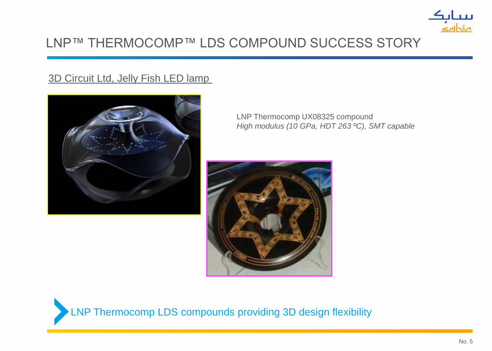
LNP™ THERMOCOMP™ LDS COMPOUND SUCCESS STORY
LNP Thermocomp UX08325 compound
High modulus (10 GPa, HDT 263 ºC), SMT capable
3D Circuit Ltd, Jelly Fish LED lamp
LNP Thermocomp LDS compounds providing 3D design flexibility

No. 6
LN
P T
HE
RM
OC
OM
P L
DS
C
OM
PO
UN
DS
PC/ABS compounds
NX10302
NX11302
PC compounds
DX11354
DX11355
DX11354X
DX13354
PA compounds
UX08325
UX08305
Black, easy plating
White, easy plating
Black, high flow, superior impact
Black, UL94 V0 @ 0.6mm, high flow, superior impact
White, high flow, superior impact
30GF, TM > 8 GPa, excellent surface
High T PA, 30GF, HDT 263 ºC, SMT capable
UL94 V0 @ 0.8mm, HDT 267 ºC, SMT capable
LNP™ THERMOCOMP™ LDS COMPOUNDS PRODUCT PORTFOLIO

THERMAL MANAGEMENT

No. 8
THERMAL MANAGEMENT
0.0
0.5
1.0
1.5
2.0
2.5
3.0
3.5
4.0
0 0.2 0.4 0.6 0.8
Voltage (V)
Cu
rren
t (A
)
25 C 45 C 60 C
Heat builds up in electronics leading to reduced lifetime, and/or efficiency

No. 9
LNP™ Konduit™ compounds High thermal conductivity
Inherent electrical isolative
Flame retardant acc. UL94
Self Colored
Valox and/or Lexan resins
Flow
White color (high reflection)
Lexan™ polycarbonate resins Transparant and diffusion grades
UL94 V0 > 1mm / 5VA @ 3mm
Higher heat grades
Improved weather-ability grades
Typical requirements
UL 94 V0 (Nafta) UL 94 HB (RoW) Break-down voltage: 4KV Dielectric strength 1.2m drop test HDT>100C High thermal conductivity: working temp <75C Thermal cycle test HWI=4 / HAI=3 CTI=4 Paintable or in-colored For external surface >65C, RTI required
LED APPLICATIONS REQUIRE THERMAL MANAGEMENT
Metal substitution, enhancing part & function integration with LNP Konduit compounds
Valox™ resins Non brominated & chlorinated FR
Valox ENH4565
Sustainable grade Valox IQNH4550
Bulb
LED module
Thermal pad
Heat sink
Base holder
Potting glue
PCB module

No. 10
THERMALLY CONDUCTIVE PLASTICS
High thermal conductivity
Good mechanical strength
Poor electrical isolative property
Heavy weight
Poor productivity
More often 2nd operation needed
Less thermal conductivity
Less mechanical strength
Good electrical isolative property
Improved design flexibility
Lower energy demand
Light weighting
Increased productivity
Potential cost saving depending on design
Metal Thermal conductive compounds
Today metal is the common material used for heat sinks in LED lighting, but
thermal conductive thermoplastic compounds are increasingly used.
Metal substitution: integrating part & function with LNP™ Konduit™ compounds

No. 11
11
Metals Plastics
TCC's Unfilled Plastics
0
100
200
300
400
500
Th
erm
al C
on
du
ctiv
ity (W
m/K
)
0
2
4
6
8
Th
erm
al C
on
du
ctiv
ity (W
m/K
)
LNP™ KONDUIT™ COMPOUNDS FOR THERMAL MANAGEMENT
TCC may work as most heat transfer applications are limited by convection
TCC’s provide 10-50 x increased
thermal conductivity compared to
unfilled, or reinforced thermoplastics
Historically plastics have not been
able to compete with metals in heat
transfer applications

THERMAL CONDUCTIVITY - MECHANISM - COMPOSITIONAL EFFECTS - PROCESSING EFFECTS
No. 13
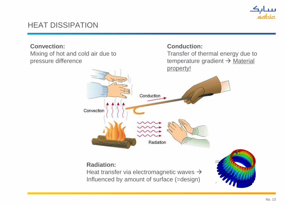
HEAT DISSIPATION
Convection:
Mixing of hot and cold air due to
pressure difference
Radiation:
Heat transfer via electromagnetic waves
Influenced by amount of surface (=design)
Conduction:
Transfer of thermal energy due to
temperature gradient Material
property!

No. 14
MECHANISM OF THERMAL CONDUCTIVITY
Vibrating atoms interact with neighboring atoms, transferring kinetic energy
Phonon = “motion of atomic and molecular vibrations”
Phonons propagate as waves at a frequency, amplitude and phase
Heat transport is reduced by scattering and collision of phonons
Simple, rigid structures are beneficial for heat transport
Polymers are thermal insulators
Good heat conductive ceramics are e.g. BN, AlN and SiC

No. 15
THERMAL VERSUS ELECTRICAL CONDUCTIVITY
Electrical conductivity
0 10 20 30 40 50 60 70
Filler fraction (vol%)
Elec
tric
al c
ondu
ctiv
ity
Ther
mal
con
duct
ivit
y
electrical conductivitythermal conductivity
-
+
-
+
High content (30 – 50 vol.%) of thermally conductive filler required

No. 16
THERMAL CONDUCTIVITY TEST EQUIPMENT
Measures diffusivity (a) and Cp
TC is calculated by: TC = a x Cp x r
Graphite coating applied
Through-plane and in-plane can be measured using
different sample holders
Netzsch NanoFlash (LFA447) HotDisk (TPS2500)
Laser
Specimen
IR detector
Measures TC directly
Measures bulk, in-plane, through-plane on sample
Variable geometries (e.g. color plaques, real-life parts)
According ASTM E-1461 According ISO 22007-2
Laser-flash method Hot disc - Transient plane heat source
State of the art test equipment to ensure reliable and reproducible data

No. 17
THERMAL CONDUCTIVITY – CRITICAL PARAMETERS
Orientation
Filler dispersion
Polymer-Filler Interface
Polymer Filler(s)
Processing
Particle size
Filler type(s)
Particle shape
Filler content Polymer type
Crystallinity
The higher the TC of the base
polymer, the higher the TC of
the compound
TC crystalline resin >>
amorphous resins
Base resin viscosity + filler
loading determines injection
moldability
Crystalline resins allow for
higher filler levels with good
processability
Thermal conductivity is influenced by 3 main variables
Understanding all application requirements is key to success

No. 18
ip
1mm, Pinpoint-gated 12.7mm disc
3mm, Pinpoint-gated 12.7mm disc
3mm, film-gated 60*60MM plaque
Nanoflash TCtp= 2.4 W/mK TCtp=4.1 W/mK TCtp=1.1 W/mK
Hotdisk TCBulk = 3.8 W/mK
TCtp = 0.8 W/mK
Tcip = 16.4 W/mK
PROCESSING EFFECTS ON LNP™ KONDUIT™ PX08321
tp
TCBulk = SQRT(TCtp*Tcip)
TCtp = Through-plane thermal conductivity
Tcip = In-plane thermal conductivity
Part design crucial for heat dissipative performance

No. 19
LNP™ KONDUIT™ COMPOUNDS PRODUCT PORTFOLIO
UV Stabilized compounds available: LNP Konduit PX11313 and PX11311U

No. 20
LNP™ KONDUIT™ SUSTAINABILITY

HEAT SINK PERFORMANCE

No. 22
Krauss Maffei 50T IMM Prototype Tooling Data acquisition system GWINSTEK DC Power Gauge R&R OK
H eat S in k D issipation P erform an ce
45
55
65
75
85
95
105
115
2 2.5 3 3.5 4 4.5 5 5.5 6 6.5 7 7.5 8
P ow er(W )
Heat
er T
emp(
Degr
ee C
)
D ie C asting A l P X 08321-insert P X 08322-insert
P X 09322-insert E X K D 0033-insert E X K D 0012-insert
N on-TC P A 6-insert P X 08321-no insert P X 08322-no insert
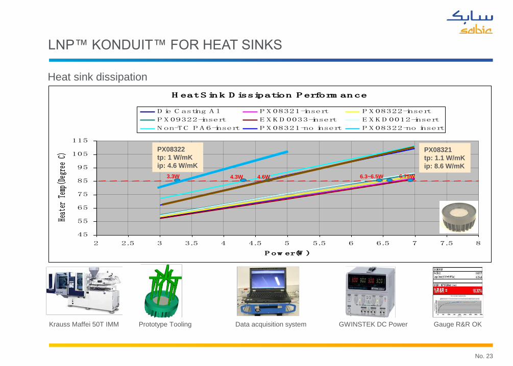
3.3W 6.3~6.5W 6.75W 4.6W 4.3W
LNP™ KONDUIT™ FOR HEAT SINKS
Heat sink dissipation
No. 23
LNP™ KONDUIT™ FOR HEAT SINKS
H eat S in k D issipation P erform an ce
45
55
65
75
85
95
105
115
2 2.5 3 3.5 4 4.5 5 5.5 6 6.5 7 7.5 8
P ow er(W )
Heat
er T
emp(
Degr
ee C
)
D ie C asting A l P X 08321-insert P X 08322-insert
P X 09322-insert E X K D 0033-insert E X K D 0012-insert
N on-TC P A 6-insert P X 08321-no insert P X 08322-no insert
3.3W 6.3~6.5W 6.75W 4.6W 4.3W
PX08322
tp: 1 W/mK
ip: 4.6 W/mK
PX08321
tp: 1.1 W/mK
ip: 8.6 W/mK
Heat sink dissipation
Krauss Maffei 50T IMM Prototype Tooling Data acquisition system GWINSTEK DC Power Gauge R&R OK

No. 24
H eat S in k D issipation P erform an ce
45
55
65
75
85
95
105
115
2 2.5 3 3.5 4 4.5 5 5.5 6 6.5 7 7.5 8
P ow er(W )
Heat
er T
emp(
Degr
ee C
)
D ie C asting A l P X 08321-insert P X 08322-insert
P X 09322-insert E X K D 0033-insert E X K D 0012-insert
N on-TC P A 6-insert P X 08321-no insert P X 08322-no insert
3.3W 6.3~6.5W 6.75W 4.6W 4.3W
PA6+stamped Al-insert
Increasing TC
LNP™ KONDUIT™ FOR HEAT SINKS
Heat sink dissipation
Krauss Maffei 50T IMM Prototype Tooling Data acquisition system GWINSTEK DC Power Gauge R&R OK

No. 25
MODELING – 100% THERMOPLASTIC HEAT SINK
Cylinder has material property
distribution as shown
Disc has material property
distribution as shown
Radial Hoop Axial
TH-PLANE IN-PLANE IN-PLANE
k1 k2 k3
Radial Hoop Axial
IN-PLANE IN-PLANE TH-PLANE
k1 k2 k3
Peak temperature

No. 26
HYBRID HEAT SINKS – ANALYTICAL MODELING
Convective
Cooling (15W/m2-k) Heat source
d

No. 27
Two times sur.area Two times sur.area
Al Konduit Konduit + Al
Small sur.area Hybrid design
concept
90.32ºC 6 rib
(16000)
0 rib
(14000)
12 rib
(18000)
24 rib
(22000)
3300
Long Al Insert
84.45ºC
92.9ºC
86.58ºC
6 rib
(16000)
0 rib
(14000)
12 rib
(18000)
24 rib
(22000)
3300
Long Al Insert(Slot)
84.37ºC
86.63ºC
93.27ºC
1300
Short Al Insert
0 rib
(14000)
6 rib
(16000)
12 rib
(18000)
24 rib
(22000) 89.32ºC
91.50ºC
94.17ºC
97.62ºC
6 rib
(16000)
0 rib
(14000)
12 rib
(18000)
24 rib
(22000)
1300
Short Al Insert(slot)
90.39ºC
92.73ºC
97.81ºC
Increase surface area very effective to improve heat dissipation
DoE & Performance Testing
HYBRID HEAT SINKS – DESIGN ASPECTS

No. 28
HEAT SHOCK PERFORMANCE
Complex phenomenon, main controlling factors
• CTE mismatch
• Elongation at break (PX11311 and PX11311U)
• Design smoothly finned
More stringent test
Complete part design critical

THERMAL CONDUCTIVE LDS COMPOUNDS

No. 30
30
POTENTIAL VALUE PROPOSITION
What is it that you need for you next MID solution?
Why combining thermal conductivity with laser direct structuring capability?
Heat dissipation often needed in miniaturized electronic applications
Helps thermal management challenges with electronic circuitry, or in higher heat environments
Enhanced design freedom with surface mount technology (SMT), or laser welding
• May eliminate need for thermally conductive interface pads, and adhesives
Initial questions:
Level of isolative thermal conductivity needed? In Plane/Through Plane?
Temperature range required? Dimensional stability as f(T)?
(Halogen free) FR needed? Only dark, or also lighter colors?
Connection technology preferred?
Thermal conductive LDS compound proposed:
TCip ~ 3 W/mK & TCtp ~ 1.2 W/mK
Peel strength > 0.7 N/mm & Target 1 N/mm
Base resin preferred?

No. 31
DISCLAIMER
DISCLAIMER: THE MATERIALS, PRODUCTS AND SERVICES OF SABIC INNOVATIVE PLASTICS HOLDING B.V. ITS
SUBSIDIARIES AND AFFILIATES (“SELLER”), ARE SOLD SUBJECT TO SELLER’S STANDARD CONDITIONS OF
SALE, WHICH CAN BE FOUND AT http://www.sabic-ip.com AND ARE AVAILABLE UPON REQUEST. ALTHOUGH ANY
INFORMATION OR RECOMMENDATION CONTAINED HEREIN IS GIVEN IN GOOD FAITH, SELLER MAKES NO
WARRANTY OR GUARANTEE, EXPRESS OR IMPLIED, (i) THAT THE RESULTS DESCRIBED HEREIN WILL BE
OBTAINED UNDER END-USE CONDITIONS, OR (ii) AS TO THE EFFECTIVENESS OR SAFETY OF ANY DESIGN
INCORPORATING SELLER’S PRODUCTS, SERVICES OR RECOMMENDATIONS. EXCEPT AS PROVIDED IN
SELLER’S STANDARD CONDITIONS OF SALE, SELLER SHALL NOT BE RESPONSIBLE FOR ANY LOSS RESULTING
FROM ANY USE OF ITS PRODUCTS OR SERVICES DESCRIBED HEREIN. Each user is responsible for making its own
determination as to the suitability of Seller’s products, services or recommendations for the user’s particular use through
appropriate end-use testing and analysis. Nothing in any document or oral statement shall be deemed to alter or waive any
provision of Seller’s Standard Conditions of Sale or this Disclaimer, unless it is specifically agreed to in a writing signed by
Seller. No statement by Seller concerning a possible use of any product, service or design is intended, or should be
construed, to grant any license under any patent or other intellectual property right of Seller or as a recommendation for the
use of such product, service or design in a manner that infringes any patent or other intellectual property right.
Brands marked with ™ are trademarks of SABIC.
© 2012 Saudi Basic Industries Corporation (SABIC). All Rights Reserved.


![[LNP] Durarara!! Vol.4 Cap.1](https://static.documents.pub/doc/80x56/577cd5a11a28ab9e789b4a5d/lnp-durarara-vol4-cap1.jpg)


