

Lunar Relativistic Positioning System for human exploration
Luca Levrino [email protected]
Luigi Colangelo, Giacomo Gatto, Jeffrey A. Hoffman, Nicola Linty, Angelo Tartaglia
Massachusetts Institute of Technology and Politecnico di Torino
November 19 2014
2nd UNISEC-Global Meeting Kyushu Institute of Technology, Kitakyushu, Japan
Introduction Concept of Operations Space Segment Ground Segment Implementation Conclusions

Mission Need Future of human space exploration:
INTRODUCTION
3

Mission Need Future of human space exploration: • Moon, Mars, … • Permanent outposts (e.g. lunar South Pole) • Planetary exploration: why?
Scientific activities (samples, water ice, minerals, …) In-situ resource utilization (outpost sustainment)
• Planetary exploration: how? Around the base Far from the base
• Rovers Manned and unmanned Pressurized and not pressurized
• Positioning/Navigation becomes a major problem Need for a navigation system, like GPS, GLONASS, Galileo, Beidou on Earth Simple to setup (e.g. no synchronization) Cost effective (e.g. cost of Moon launches, atomic clocks, …)
Requirements
INTRODUCTION
4
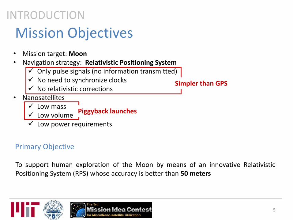
Mission Objectives • Mission target: Moon • Navigation strategy: Relativistic Positioning System
Only pulse signals (no information transmitted) No need to synchronize clocks No relativistic corrections
• Nanosatellites Low mass Low volume Low power requirements
Piggyback launches
Primary Objective
To support human exploration of the Moon by means of an innovative Relativistic Positioning System (RPS) whose accuracy is better than 50 meters
INTRODUCTION
Simpler than GPS
5

Introduction Concept of Operations Space Segment Ground Segment Implementation Conclusions

Relativistic Positioning • Exploit relativity instead of correcting it! • 4D grid covering space-time drawn thanks to reception of signals
CONCEPT OF OPERATIONS
Light cone
Light cone
• Null geodesics χ 4D curves along which light and EM
signals propagate Express space-time position of each
emitting source • Vectors χa, χb, χc, χd: base of 4D space • To localize an event r in space time
At least 4 sources emitting pulses Count pulses Know where sources are and their
pulse period
χ
time
space
event
r χa
χb r =t a
Taca +
t b
Tbcb +
t c
Tccc +
t d
Tdcd
7
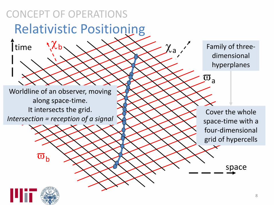
Relativistic Positioning CONCEPT OF OPERATIONS
b
b
time
space
a
a
Family of three-dimensional hyperplanes
Worldline of an observer, moving along space-time.
It intersects the grid. Intersection = reception of a signal
Cover the whole space-time with a four-dimensional grid of hypercells
8
Introduction Concept of Operations Space Segment Ground Segment Implementation Conclusions
Signals Orbits Subsystems

Signals • Nanosatellites emit periodic radar-like electromagnetic Radio Frequency signals • Gaussian pulse, modulated by a sinusoidal carrier in the S band (2.2 GHz) • Pulse width: 10 µs • Each satellite has a different pulse period • Pulse periods spaced by 10 µs
e.g. T1=100 µs, T2=110 µs, T3=120 µs
SPACE SEGMENT
0 50 100 150 200 250 300-1
-0.5
0
0.5
1
Time (s)
No
rma
lize
d a
mp
litu
de
Satellite 1
Satellite 2
Satellite 3T
3
T1
T2
10

Introduction Concept of Operations Space Segment Ground Segment Implementation Conclusions
Signals Orbits Subsystems

Orbits and Constellation 1. Area of interest: South Pole and surroundings 2. Stable orbits 3. At least 4 satellites in view
SPACE SEGMENT
Requirements
1. High eccentricity, longitude of the ascending node = 0°, argument of perilune = 90°
2. Frozen orbits: Δe=Δω=0, J2+J3+J5≈0 3. 6 satellites
• a = 8000 km • e = 0.76 • i = 60° and 120° • T ≈ 18 hours • M accordingly spaced
12

Geometric Dilution Of Precision
• Accuracy of positioning depends also on a geometry factor
• GDOP is a measure of the composite effect of the relative satellite/user geometry
• Strictly depends on azimuth and elevation of satellites in view
• Expected average GDOP on different points of the lunar surface in a region centered at the South Pole along 18 hours with the 6 satellites constellation
SPACE SEGMENT
13

Orbits and Constellation
• Increase accuracy Geometry # satellites increase
• Add 6 satellites a = 5000 km e = 0.41 i = 45° and 135° T ≈ 9 hours M accordingly spaced
• GDOP with 12 satellites
SPACE SEGMENT
14

Introduction Concept of Operations Space Segment Ground Segment Implementation Conclusions
Signals Orbits Subsystems

Nanosatellites • 2U
External size≈10x10x20 cm Internal volume≈1900 cm3
• Design maximizes use of COTS
SPACE SEGMENT
Subsystem Mass (kg) Volume (cm3) Power (W) AODCS 1.25 656 1.5
EPS 1.27 397 0.8
OBC 0.10 107 0.4
Clock 0.05 17 0.2
Structure 0.39 - - Comm 0.20 74 1.0
Total 3.90 1501 4.6
16

AODCS • Sensors
Sun sensors MEMS gyros (3-axes) IMU close to center of mass
3-axes accelerometer 3-axes gyro
• Actuators 1 Pulse Plasma Thruster (PPT)
Isp=500-600 s Orbit insertion Boost orbit lifetime (10 years) mp=0.3 kg
2 electrospray thrusters Microfabricated Electrospray Arrays Isp=2500-5000 s Fine pointing mode Mission mode mp=0.1 kg
SPACE SEGMENT
17

EPS • Requirements
Average power ≈ 5 W Eclipse: max 1 hour Daytime: worst case 8 hours Long eclipses not considered
4-6 hours Only twice a year Standby mode
• Solar panels 8 GaAs arrays
2.3 W power each 60 g each
• Storage 2 Li-Ion batteries
40 Wh each 240 g each
SPACE SEGMENT
18

Clock
• Scale atomic clock QuantumTM SA.45s CSAC 120 mW 35 g
• Stability Allan deviation 8x10-12 at
observation time t=1000-10000 s
Positioning error ±9 m Clock update every 3 h
Temperature stability box with a high
reflectivity index
SPACE SEGMENT
19

Communication
• S-Band: 2.2 GHz • Antenna
6 dBi gain 60° beamwidth
• Power amplifier (transmitter) 1 W
• Link False alarm probability of 10-5
Detection probability of 0.9
SPACE SEGMENT
20

Introduction Concept of Operations Space Segment Ground Segment Implementation Conclusions
Ground Station
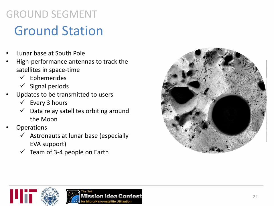
• Lunar base at South Pole • High-performance antennas to track the
satellites in space-time Ephemerides Signal periods
• Updates to be transmitted to users Every 3 hours Data relay satellites orbiting around
the Moon • Operations
Astronauts at lunar base (especially EVA support)
Team of 3-4 people on Earth
GROUND SEGMENT
22

Users
• Manned/unmanned rovers • Antenna: gain 30 dBi and system temperature 290 K • Front-end + Analog to Digital Converter + Clock
Detect pulses in time and frequency domain Identify the emitting satellite by computing the
pulses period Compute the time interval between two signals
from two different emitters
GROUND SEGMENT
23
0 50 100 150 200 250 300-1
-0.5
0
0.5
1
Time (s)
No
rma
lize
d a
mp
litu
de
Satellite 1
Satellite 2
Satellite 3T
3
T1
T2
Positioning Accuracy
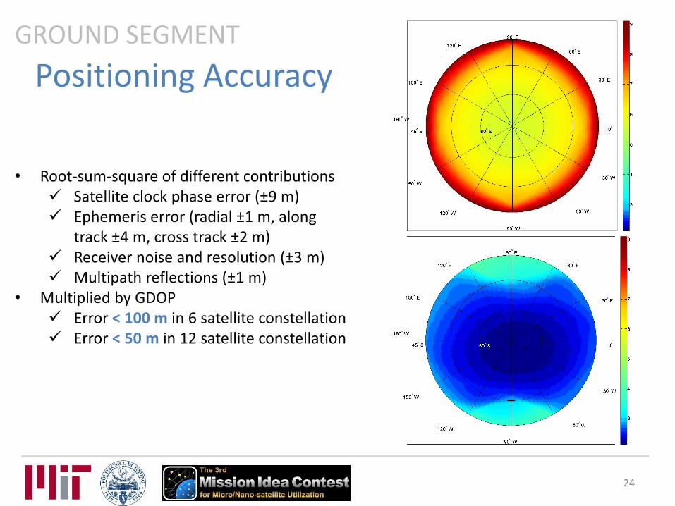
• Root-sum-square of different contributions Satellite clock phase error (±9 m) Ephemeris error (radial ±1 m, along
track ±4 m, cross track ±2 m) Receiver noise and resolution (±3 m) Multipath reflections (±1 m)
• Multiplied by GDOP Error < 100 m in 6 satellite constellation Error < 50 m in 12 satellite constellation
GROUND SEGMENT
24

Introduction Concept of Operations Space Segment Ground Segment Implementation Conclusions

Project Schedule IMPLEMENTATION
26

Cost Analysis
• Cost of one nanosatellite ≈ 150 k$ • Design, assembly, development, integration and
testing Team of 15-20 people 4-5 years Average salary of 70-100 k$ per year per
person Prototype cost ≈ 0.5-1 M$
• Launch costs for 12 cubesats ≈ 0.6 M$ • Operations
Team of 3-4 people 10 years
• Disposal: de-orbit propellant already considered • Total ≈ 15 M$
IMPLEMENTATION
27

Introduction Concept of Operations Space Segment Ground Segment Implementation Conclusions

Potential Risks and Solutions • Competition with existing technologies
Earth GPS on the Moon Good results Limited availability
LRPS Reduced complexity and low cost Very good coverage and GDOP Also on other planets
• False alarm and detection probabilities High gain receiver antennas Advanced signal processing techniques
• Orbit stability Mascons not well determined Orbit control system included
• Maintenance Redundancies in constellation size
CONCLUSIONS
29

Project Sustainability
• Components Off The Shelf Low development and construction costs Standardized size
• Launch Piggyback Decrease in launch costs
• Not particular ground infrastructure to build • Mission architecture easily extendable to cover
the whole Moon • Support spacecraft landing on the Moon • A similar idea could be used to improve GPS
coverage at Earth poles
CONCLUSIONS
30

Thank you!
ありがとうございました

Back up slides

Relativistic Positioning

Relativistic Positioning • Exploit relativity instead to correct it! • Four dimensional grid covering space-time drawn thanks to reception of signals • No need to synchronize clocks • No need to define origin of time • No relativistic corrections
Simpler than GPS
CONCEPT OF OPERATIONS
Light cone
Light cone
• Null geodesics Null tangent (wave) vector
• Vectors χa, χb, χc, χd: base of 4D space
Direction cosines Period of the signal
0
34

Relativistic Positioning CONCEPT OF OPERATIONS
time
space
event
r
light coordinates
d
d
d
c
c
c
b
b
b
a
a
a
TTTTr
χa
χb
35

Relativistic Positioning CONCEPT OF OPERATIONS
b
b
time
space
a
a Family of null
three-dimensional hypersurfaces
36

Relativistic Positioning CONCEPT OF OPERATIONS
time
space
Ta
Tb
1 2
3
4
1
4
3
2
dcbadcba Txn ,,,,,,
• Discrete grid, locally uniform motion Proper time
integer
From simple linear equations
d
d
d
c
c
c
b
b
b
a
a
a
TTTTr
b a
37

AODCS

AODCS • Attitude and orbit perturbations
Third body effect due to Earth and Sun gravity Forces due to solar radiation and wind Commanded thrust forces
SPACE SEGMENT
39
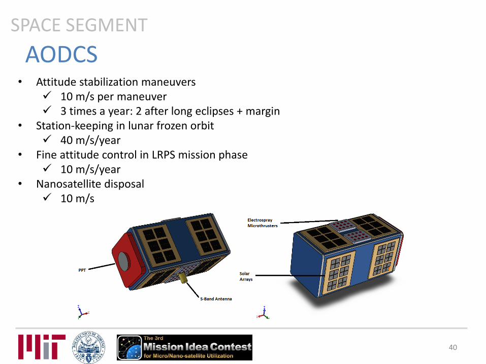
AODCS • Attitude stabilization maneuvers
10 m/s per maneuver 3 times a year: 2 after long eclipses + margin
• Station-keeping in lunar frozen orbit 40 m/s/year
• Fine attitude control in LRPS mission phase 10 m/s/year
• Nanosatellite disposal 10 m/s
SPACE SEGMENT
40

AODCS: control modes • Separation and de-tumbling mode.
attitude uncertainty: about 5° spinning velocity about the x-axis accurate antenna orientation is not required colloidal microthrusters reduce the tumbling motion under a certain threshold.
• Attitude and orbit acquisition mode. attitude and orbit starting points uncertainty: 5°, at most.
• Orbit insertion mode. error affecting position and velocity vectors below a defined threshold.
• Fine attitude acquisition and pointing mode. Nadir-pointing control strategy attitude uncertainty: 1-2°
• LRPS Mission mode. on-board systems checked and working. orbit control system (firing the PPT)
• Safe mode. eclipse periods/in case of failure minimum amount of power
SPACE SEGMENT
41

AODCS: proposed hardware – SENSORS 1/2 SPACE SEGMENT
Sun sensors Photo-diodes integrated in the solar panels Current: 170 uA Field of view: 114° Update Rate: >10 Hz (limited by ADC) Accuracy: <0.5°
MEMS gyros integrated in the solar panels (3-axes)
Range: 80 °/s Sensitivity: 0.00458 °/s Bias stability: 0.016 °/s Vcc: 5 V Current: 44 mA
42

AODCS: proposed hardware – SENSORS 2/2 SPACE SEGMENT
IMU (6 Degrees of Freedom on a single, flat board): ITG-3200 - triple-axis digital-output gyroscope
• Digital-output X-, Y-, and Z-Axis angular rate sensors (gyros) on one integrated circuit • Digitally-programmable low-pass filter • Low 6.5mA operating current consumption for long battery life • Wide VDD supply voltage range of 2.1V to 3.6V • Standby current: 5μA • Digital-output temperature sensor • Fast Mode I2C (400kHz) serial interface • Optional external clock inputs of 32.768kHz or 19.2MHz to synchronize with system clock
ADXL345 - 13-bit resolution, ±16g, triple-axis accelerometer • 1.8V to 3.6V supply • Low Power: 25 to 130uA @ 2.5V • SPI and I2C interfaces • Up to 13bit resolution at +/-16g • Activity/Inactivity monitoring • Free-Fall detection
Outputs of all sensors processed by on-board ATmega328 processor and sent out via a serial stream 3.5-16VDC input Dimensions: 1.1" x 1.6" (28 x 41mm)
43
AODCS: attitude perturbations (torques) 1/2 SPACE SEGMENT
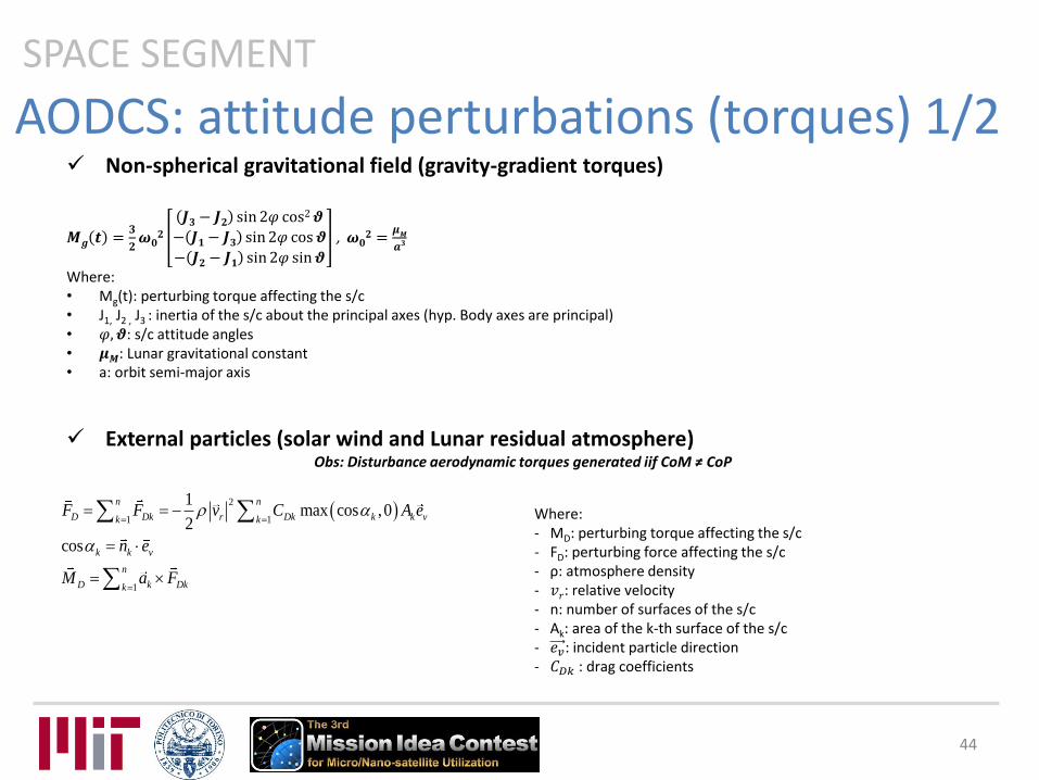
Non-spherical gravitational field (gravity-gradient torques)
𝑴𝒈 𝒕 =𝟑
𝟐𝝎𝟎𝟐
𝑱𝟑− 𝑱𝟐 sin2𝜑 cos2𝝑
− 𝑱𝟏− 𝑱𝟑 sin2𝜑 cos 𝝑
− 𝑱𝟐− 𝑱𝟏 sin2𝜑 sin𝝑
, 𝝎𝟎𝟐 =𝝁𝑴𝒂𝟑
Where: • Mg(t): perturbing torque affecting the s/c • J1, J2 , J3 : inertia of the s/c about the principal axes (hyp. Body axes are principal) • 𝜑, 𝝑: s/c attitude angles • 𝝁𝑴: Lunar gravitational constant • a: orbit semi-major axis
External particles (solar wind and Lunar residual atmosphere) Obs: Disturbance aerodynamic torques generated iif CoM ≠ CoP
Where: - MD: perturbing torque affecting the s/c - FD: perturbing force affecting the s/c - ρ: atmosphere density - 𝑣𝑟: relative velocity - n: number of surfaces of the s/c - Ak: area of the k-th surface of the s/c - 𝑒𝑣: incident particle direction - 𝐶𝐷𝑘 : drag coefficients
2
1 1
1
1max cos ,0
2
cos
n n
D Dk r Dk k k vk k
k k v
n
D k Dkk
F F v C A e
n e
M a F
44

SPACE SEGMENT
AODCS: attitude perturbations (torques) 2/2
Electromagnetic waves (photons) from Sun (radiation solar pressure) and Moon emitted/reflected radiation
Obs: Disturbance torque generated iif CoM ≠ CoP
The resulting pressure depends on: • the vehicle geometry, • the radiation direction in the body frame, • the optical properties of the surface. The incident electromagnetic may be: • completely absorbed by the surface, • specularly reflected, • diffusely reflected in any direction, • transmitted.
1 1
1 2 max cos ,0 / 3 max cos ,0
cos
n n
r rk sk sk k dk k k kk k
k k
F F p C s C C n A
s n
1
n
r k rkkM a F
Where: • Mr: perturbing torque affecting the s/c • Fr: perturbing force affecting the s/c • n: number of surfaces of the s/c • Ak: area of the k-th surface of the s/c • 𝐶𝑠𝑘 , 𝐶𝑑𝑘: specular and diffusion coefficients • α: angle of incidence • p: pressure of the electromagnetic radiation • 𝑛𝑘: outer normal direction of the k-th surface of the s/c
45

AODCS: orbit perturbations (forces) SPACE SEGMENT
Third-body effects: Earth and Sun
𝐹(𝑡) ≅ 𝑚 −𝜇𝑗𝑟
𝑟𝑗3
𝒓
𝑟− 3𝒓𝒋𝑟𝑗cos 𝛼
𝑛−1
𝑗=2
Where: • F(t): perturbing force affecting the s/c • m: s/c mass • n: number of space bodies taken into account • μj: j-th body gravitational constant • rj: j-th body radius • r: satellite radius • α: angle of view
Aerodynamic forces and wind (residual atmosphere)
𝐹 = −1
2𝜌𝑣𝑟2 𝐶𝑛,𝑘𝑛𝑘 + 𝐶𝑣,𝑘𝑒𝑣 𝐴𝑘
𝑛−1
𝑘=0
Where: • F: perturbing force affecting the s/c • ρ: thermosphere density • 𝑣𝑟: relative velocity • n: number of surfaces of the s/c • Ak: area of the k-th surface of the s/c • 𝑛𝑘: outer normal direction of the k-th surface of the s/c • 𝐶𝑛,𝑘 , 𝐶𝑣,𝑘: mixed aerodynamic coefficients
46

EPS

EPS: solar panels SPACE SEGMENT
8 GaAs arrays
Single panel properties: Power: 2.3 W Operational temperature: -40 oC to +85 oC Dimensions: 82.5mm x 98.0mm x 2.1mm Height of connectors: 4.8 mm Height of gyro: 5.5 mm Panel thickness: 2.15 mm Mass: 60 g
Single panel further features:
Two series-connected AzurSpace 3G-30 space qualified triple junction solar cells + protection diodes
Integrated magnetorquer of 1.6 m2
Coarse sun sensor Temperature sensor Gyro-scope model ADIS16251 (0.004 o/s) Top/Bottom or side panel version
48

Signal

Receiver block scheme GROUND SEGMENT
clock
pulse replica
Assistance data
matched filter
LRPS algorithm
ADC
~
antenna
f0=2.2 GHz
fs=100 MHz
fLO
DSP
01001011 10100101
50
band pass filter
user position
50

Signal acquisition strategies GROUND SEGMENT
51
Synchronization problem: 1. CDMA modulation (similar to GPS)
Orthogonal codes Despreading gain Robust to AWGN Allows signal identification More complex receiver
2. Edge detector Time domain analysis Detect pulse rising edge Limited resolution
3. Pulses modulation and matched filter Correlation with local replica of signal Simple solution Optimal filter to maximize SNR
51

False alarm and detection probabilities GROUND SEGMENT
𝑃𝑓𝑎 𝛽 = 𝑃 𝑋 > 𝛽|𝐻0
𝑃𝑑 𝛽 = 𝑃 𝑋 > 𝛽|𝐻1
𝑃𝑚𝑑 𝛽 = 1 − 𝑃𝑑 𝛽
False alarm probability: 𝑃𝑓𝑎
Detection probability: 𝑃𝑑
Where: 𝐻0 is the hypothesis of signal absence 𝐻1 is the hypothesis of signal presence is a determined acquisition threshold 𝑋 is the generic random variable related to the search space
52

Link Budget SPACE SEGMENT
53
𝑃𝑇 >𝜂 4𝜋𝐷 2𝐾𝑇𝑜𝑝
𝐺𝑇𝑋𝐺𝑅𝑋𝜆2𝑇
𝑃𝑓𝑎 = 10−5
𝑃𝑑 = 0.9
𝑏
𝜎= 4.8
𝜂 = 12.5 dB
• Classical link budget cannot be used: no data rate, because no data are transmitted • Radar approach, based on false alarm and detection probabilities
D: distance K: Boltzmann constant 𝐺𝑇: TX antenna gain 𝐺𝑅: RX antenna gain 𝜆: wavelength 𝑇: pulse width
Given a target false alarm probability, 𝑏/𝜎 is derived:
Given a target detection probability, 𝜂 is derived:
The minimum transmit power is computed:

Orbits

Orbits SPACE SEGMENT
• Extensive flight time over south pole • Eccentric • Longitude of ascending node = 0° • Argument of perilune = 90°
• Stability
• Frozen orbits 𝑒 = 1 −5
3cos2 𝑖
12
• Null variations of eccentricity and argument of perilune due to compensation of J2, J3, J5
• Librating orbits • Quasi-periodic variations of eccentricity and argument of perilune
• Coverage and precision
• 6 satellites for first constellation (100 m positioning error) • 12 satellites for final constellation (50 m positioning error)
55

Frozen Orbits SPACE SEGMENT
𝑑𝜔
𝑑𝑡= 0
𝑑𝑒
𝑑𝑡= 0
Excluding trivial cases, i.e. equatorial (i=0°,180°), circular (e=0), escape (e=1), we can find solutions for the eccentricity rate when 𝜔 = 90°, 270°. Now, the perilune rate is null for
𝜔 = 90°, 270° ⇒ 𝑒 = 1 −5
3cos2 𝑖
12
56

Orbits SPACE SEGMENT
𝑒 = 1 −5
3cos2 𝑖
12
e = 0.4028, i = 45°, 135°
e = 0.7638, i = 60°, 120°
𝜔 = 90°, 270°
57

Ground Tests

Ground Tests SPACE SEGMENT
59
Test Q/A Description
Static load tests Q The flight structure is held in a rigid test stand representing the launch vehicle adapter and subjected to limit, yield and ultimate loads through hydraulic jacks.
Spin test Q Required to simulate the spinning motion after launcher separation.
Sinusoidal vibration test
Q, A A shaker subjects the spacecraft to a “sweep” of sinusoidal frequencies according to the values prescribed in the launch vehicle manual.
Shock test Q Shocks like shroud jettison and spacecraft separation are simulated.
Physical properties test
Q, A Mass, center of gravity and moments of inertia are determined, needed for attitude control design and for the setup of other mechanical tests.
Thermal vacuum tests
Q, A Verification of the electrical functionality in the vacuum of space under the extreme temperatures to which the spacecraft will be subjected.
Thermal balance test
Q Simulation of the mission thermal environment (solar radiation, albedo, internal dissipation), performed in a vacuum solar simulation chamber.
Electromagnetic compatibility test
Q, A The possibility of electromagnetic interference from external sources is analyzed. This test is run in an anechoic room.


