

MagnecraftGeneral Purpose RelaysCatalog
2014

2
Contents Magnecraft™ General Purpose Relays
b Series Overview . . . . . . . . . . . . . . . . . . . . . . . . . . . . . . . . . . . . . . . . . . . . . . . . . . . .3
b 792 Control Series . . . . . . . . . . . . . . . . . . . . . . . . . . . . . . . . . . . . . . . . . . . . . . . . . .4
b 781 Series . . . . . . . . . . . . . . . . . . . . . . . . . . . . . . . . . . . . . . . . . . . . . . . . . . . . . . . .9
b 782 Power Series . . . . . . . . . . . . . . . . . . . . . . . . . . . . . . . . . . . . . . . . . . . . . . . . . .13
b 783 Series . . . . . . . . . . . . . . . . . . . . . . . . . . . . . . . . . . . . . . . . . . . . . . . . . . . . . . .17
b 784 Series . . . . . . . . . . . . . . . . . . . . . . . . . . . . . . . . . . . . . . . . . . . . . . . . . . . . . . .21
b 750 Series . . . . . . . . . . . . . . . . . . . . . . . . . . . . . . . . . . . . . . . . . . . . . . . . . . . . . . .25
b 788 Series . . . . . . . . . . . . . . . . . . . . . . . . . . . . . . . . . . . . . . . . . . . . . . . . . . . . . . .29
b 782H Hazardous Location Series . . . . . . . . . . . . . . . . . . . . . . . . . . . . . . . . . . . . .33
b 750H Hazardous Location Series . . . . . . . . . . . . . . . . . . . . . . . . . . . . . . . . . . . . .37
b UL Listed Relay/Socket Combinations . . . . . . . . . . . . . . . . . . . . . . . . . . . . . . . . . .41
b Sockets and Accessories . . . . . . . . . . . . . . . . . . . . . . . . . . . . . . . . . . . . . . . . . . . .42
v Socket Specifications . . . . . . . . . . . . . . . . . . . . . . . . . . . . . . . . . . . . . . . . . . . . 42
v Mounting Adapter Specifications . . . . . . . . . . . . . . . . . . . . . . . . . . . . . . . . . . . . 65
v Socket Accessories . . . . . . . . . . . . . . . . . . . . . . . . . . . . . . . . . . . . . . . . . . . . . . 66
b Application Data . . . . . . . . . . . . . . . . . . . . . . . . . . . . . . . . . . . . . . . . . . . . . . . . . . .73
b Website Guide . . . . . . . . . . . . . . . . . . . . . . . . . . . . . . . . . . . . . . . . . . . . . . . . . . . .75

3
Designed with specialized magnetic armatures and coils, Magnecraft General Purpose Relays easily handle current loads ranging from 10 mA to as large as 15 A . With multiple features, and a broad line of sockets and accessories, these relays offer the options needed to improve design, expedite installation and simplify testing of your application .
Series Overview Magnecraft General Purpose Relays
Series Features Terminals Contact Configuration Output Current Page
792 Control Plug-In Relay Blade DPDT and 4PDT 3–12 A 4
781 Plug-In Relay Blade SPDT 15 A 9
782 Power Plug-In Relay Blade DPDT 15 A 13
783 Plug-In Relay Blade 3PDT 15 A 17
784 Plug-In Relay Blade 4PDT 15 A 21
750 Plug-In Relay
Octal (8 Pin) DPDT 10 A
25
Octal (11 Pin) 3PDT 10 A
788 Plug-In Relay Blade DPDT and 3PDT 10 A 29
782H Hermetically Sealed Relay Blade 4PDT
5 A
333 A
1 A
750H Hermetically Sealed Relay
Octal (8 Pin) DPDT 12 A
37
Octal (11 Pin) 3PDT 12 A
Key Features b Socket, panel and DIN mounting options b Multiple features and contact configurations available b Optional protection, mounting, and identification accessories
b Ideal for MRO direct replacement b UL Class I Division 2 models for hazardous locations

4
Description Magnecraft General Purpose Relays792 Control SeriesDPDT 12 A; 4PDT 6 A and 3 A
DescriptionThe 792 Plug-in Control relays offer clear or full-feature covers with multiple mounting options and accessories; 4PDT models save valuable space while adding increased functionality .
Part Number Explanation
Series:792 = 792 Series Control Relay
Contact Configuration:XBX = DPDTXDX = 4PDT
Cover Options:C = Clear CoverCL = Clear Cover and LEDM4L = Locking Push Button
and LED
Coil Voltages: 12–240A = 12–240 VAC12–110D = 12–110 VDC
Contact Code:None = Standard 6–12 A
Silver Alloy Contacts3 = 3 A Bifurcated Contacts
*Please contact Customer Service for more information (847-441-2540).
792 Clear Cover
Feature Benefit12 A / 6 A / 3 A switching current
Ideal for various automation panels and controls
Clear or full-feature cover options
Full-feature covers include LED indicator and locking test button to facilitate maintenance and expedite commissioning
DPDT and 4PDT contact options
Simultaneously control 2 or 4 separate circuits
Socket mount option Simplifies installation and maintenance while also allowing the use of protection modules, hold-down clips and other accessories
Gold-flashed contacts Reduces contact oxidation and increases shelf life
Mechanical flag indicator Standard feature that displays relay status during testing or operation without having to power the relay
792 Full-Feature Cover
UL listed when used with proper Magnecraft sockets
Contact Rating
Contact Configuration
Nominal Coil Voltage
Coil Resistance (Ω) Contacts Part Number:
Clear CoverPart Number: Clear Cover with LED
Part Number: Full-Feature Cover
3 A 4PDT
12 Vac 44
Low Level Bifurcated
792XDX3C-12A 792XDX3CL-12A 792XDX3M4L-12A24 Vac 177 792XDX3C-24A 792XDX3CL-24A 792XDX3M4L-24A48 Vac 708 792XDX3C-48A 792XDX3CL-48A 792XDX3M4L-48A120 Vac 3630 792XDX3C-120A 792XDX3CL-120A 792XDX3M4L-120A240 Vac 17720 792XDX3C-240A 792XDX3CL-240A 792XDX3M4L-240A12 Vdc 160 792XDX3C-12D 792XDX3CL-12D 792XDX3M4L-12D24 Vdc 640 792XDX3C-24D 792XDX3CL-24D 792XDX3M4L-24D48 Vdc 2560 792XDX3C-48D 792XDX3CL-48D 792XDX3M4L-48D110 Vdc 13440 792XDX3C-110D 792XDX3CL-110D 792XDX3M4L-110D
12 A DPDT
12 Vac 44
Standard
792XBXC-12A – 792XBXM4L-12A24 Vac 177 792XBXC-24A – 792XBXM4L-24A48 Vac 708 792XBXC-48A – 792XBXM4L-48A120 Vac 3630 792XBXC-120A – 792XBXM4L-120A240 Vac 17720 792XBXC-240A – 792XBXM4L-240A12 Vdc 160 792XBXC-12D – 792XBXM4L-12D24 Vdc 640 792XBXC-24D – 792XBXM4L-24D48 Vdc 2560 792XBXC-48D – 792XBXM4L-48D110 Vdc 13440 792XBXC-110D – 792XBXM4L-110D
6 A 4PDT
12 Vac 44 792XDXC-12A 792XDXCL-12A 792XDXM4L-12A24 Vac 177 792XDXC-24A 792XDXCL-24A 792XDXM4L-24A48 Vac 708 792XDXC-48A 792XDXCL-48A 792XDXM4L-48A120 Vac 3630 792XDXC-120A 792XDXCL-120A 792XDXM4L-120A240 Vac 17720 792XDXC-240A 792XDXCL-240A 792XDXM4L-240A12 Vdc 160 792XDXC-12D 792XDXCL-12D 792XDXM4L-12D24 Vdc 640 792XDXC-24D 792XDXCL-24D 792XDXM4L-24D48 Vdc 2560 792XDXC-48D 792XDXCL-48D 792XDXM4L-48D110 Vdc 13440 792XDXC-110D 792XDXCL-110D 792XDXM4L-110D

5
Specifications Magnecraft General Purpose Relays792 Control SeriesDPDT 12 A; 4PDT 6 A and 3 A
SpecificationsPart Number 792XBX
Contact CharacteristicsTerminal Style BladeContact Material Silver AlloyContact Configuration DPDTMaximum Switching Current 12 AMaximum Switching Voltage IEC: 250 Vac / 28 Vdc
UL/CSA: 300 Vac / 30 VdcRated Operational Current (Conforming to IEC AC-1 and DC-1)
NO: 12 A at 250 Vac, NC: 6 A at 250 Vac NO: 12 A at 28 Vdc, NC: 6 A at 28 Vdc
Rated Operational Current (Conforming to UL)
Resistive: 12 A at 277 Vac,100k cyclesResistive: 12 A at 120 Vac, 200k cyclesResistive: 12 A at 30 Vdc,100k cyclesMotor: 1/2 HP at 120 Vac, 6k cyclesMotor: 1 HP at 277 Vac, 6k cyclesB300 PILOT DUTY, 6k cycles
Minimum Switching Requirement 10 mA at 17 Vdc
Coil CharacteristicsMaximum Operating Voltage 110% (AC / DC)Maximum Pickup Voltage 80% (AC); 80% (DC)Drop-out Voltage Threshold 15% (AC); 10% (DC)Average Consumption 0 .9–1 .2 VA (AC); 0 .8–1 .1 W (DC)
General CharacteristicsElectrical Life at Rated Load 200,000 operations (where stated)Mechanical Life (Unpowered) 10,000,000 operationsOperating Time 25 ms max . at 80% rated coil voltage
20 ms max . at 100% rated coil voltageRelease time 20 ms max . (DC)
35 ms max . (AC)Impulse Withstand Voltage 4 kV (1 .2 / 50 ms)Dielectric Strength - Between Coil and Contact (AC)
2000 V(rms)
Dielectric Strength - Between Poles (AC) 2000 V(rms)Dielectric Strength - Between Contacts (AC) 1300 V(rms)Ambient Air Temperature around the Device - Storage
-40 to +85 °C (-40 to +185 °F)
Ambient Air Temperature around the Device - Operation
-40 to +55 °C (-40 to +131 °F)
Vibration Resistance - In Operation 3 g-n at 35–150 HzVibration Resistance - Not Operating 5 g-n at 35–150 HzShock Resistance - In Operation 10 g-nShock Resistance - Not Operating 30 g-nDegree of Protection (Housing Only) IP 40Weight 37 g (1 .31 oz)Agency Approvals UL with socket, UR (E164862), CE, CSA (225619), RoHS
Note: Actual product performance may vary depending on application and environmental conditions.

6
Specifications (continued) Magnecraft General Purpose Relays792 Control SeriesDPDT 12 A; 4PDT 6 A and 3 A
Specifications (continued)Part Number 792XDX 792XDX3
Contact CharacteristicsTerminal Style Blade BladeContact Material Silver Alloy BifurcatedContact Configuration 4PDT 4PDTMaximum Switching Current 6 A 3 ALoad Type Standard Low LevelMaximum Switching Voltage 300 V 300 VRated Operational Current (Conforming to IEC AC1 and DC1)
NO: 6 A at 250 Vac, NC: 3 A at 250 Vac NO: 6 A at 28 Vdc, NC: 3 A at 28 Vdc
NO: 2 A at 250 Vac, NC: 1 A at 250 Vac NO: 2 A at 28 Vdc, NC: 1 A at 28 Vdc
Operational Current (Conforming to UL)
Resistive: 6 A at 277 Vac, 200k cyclesResistive: 8 A at 120 Vac, 200k cyclesResistive: 8 A at 30 Vdc, 200k cyclesMotor: 1/3 HP at 120 Vac, 6k cyclesMotor: 1/2 HP at 277 Vac, 6k cyclesPilot Duty: B300, 6k cycles
General Purpose: 3 A at 240–277 VacGeneral Purpose: 3 A at 120 VacResistive: 3 A at 30 VdcMotor: 1/16 HP (2 .8 A FLA) at 120 VacPilot Duty: 5 A make, 0 .5 A break,
3 A continuous at 120 VacMinimum Switching Requirement 10 mA at 17 Vdc 3 mA at 5 Vdc
Coil CharacteristicsMaximum Operating Voltage 110% (AC / DC) 110% (AC / DC)Maximum Pickup Voltage 80% (AC); 80% (DC) 80% (AC); 80% (DC)Drop-out Voltage Threshold 15% (AC); 10% (DC) 15% (AC); 10% (DC)Average Consumption 0 .9–1 .2 VA (AC); 0 .8–1 .1 W (DC) 0 .9–1 .2 VA (AC); 0 .8–1 .1 W (DC)
General CharacteristicsElectrical Life at Rated Load 200,000 operations (where stated) 100,000 (gen . purpose load) operationsMechanical Life (Unpowered) 10,000,000 operations 10,000,000 operationsOperating Time 25 ms max . at 80% rated coil voltage
20 ms max . at 100% rated coil voltage25 ms max . at 80% rated coil voltage20 ms max . at 100% rated coil voltage
Release time 20 ms max . (DC)35 ms max . (AC)
20 ms max . (DC)35 ms max . (AC)
Impulse Withstand Voltage 2 .5 kV (1 .2 / 50 ms) 2 .5 kV (1 .2 / 50 ms)Dielectric Strength - Between Coil and Contact (AC)
2000 V(rms) 2000 V(rms)
Dielectric Strength - Between Poles (AC) 1600 V(rms) 1600 V(rms)Dielectric Strength - Between Contacts (AC) 1300 V(rms) 1300 V(rms)Ambient Air Temperature around the Device - Storage
-40 to +85 °C (-40 to +185 °F) -40 to +85 °C (-40 to +185 °F)
Ambient Air Temperature around the Device - Operation
-40 to +55 °C (-40 to +131 °F) -40 to +55 °C (-40 to +131 °F)
Vibration Resistance - In Operation 3 g-n at 35–150 Hz 3 g-n at 35–150 HzVibration Resistance - Not Operating 5 g-n at 35–150 Hz 5 g-n at 35–150 HzShock Resistance - In Operation 10 g-n 10 g-nShock Resistance - Not Operating 30 g-n 30 g-nDegree of Protection (Housing Only) IP 40 IP 40Weight 37 g (1 .31 oz) 37 g (1 .31 oz)Agency Approvals UL with socket, UR (E164862), CE, CSA (225619), RoHS
Note: Actual product performance may vary depending on application and environmental conditions.

7
Dimensions, Wiring Diagrams
Magnecraft General Purpose Relays792 Control SeriesDPDT 12 A; 4PDT 6 A and 3 A
1.1(27.9)
1.1(27.9)
0.83(21.0)
1.54(39.1)
0.27(7.0) 0.02
(0.5)
1.4(35.5)
0.24(6.0)
0.83(21.0)
0.24(6.0)
Full-Feature Cover Dimension
Clear Cover Dimension
Dimensions — inches (millimeters)
Wiring Diagrams
11
13
A1
5
9
14
121
21
A214
6
10
24
222
4131
87
11
34
12
44
323
424
85
A113
11
9
14
A2
14
4112
44
12
1
42
4
IECNEMA
IECNEMA
DPDT 4PDT

8
Description Magnecraft General Purpose Relays792 Control Series Accessories
DescriptionOptional sockets offer customizable, Fingersafe™ solutions including protection modules, hold-down clips, and ID tags . Sockets are DIN rail and panel mount compatible .
Relay AccessoriesDescription Function For Use
With RelaysPkg. Min.
Standard Part Number
Socket ➊ DIN/Panel mount with elevator terminals 792XBX 10 70-782EL8-1
Socket ➋ DIN/Panel mount with screw terminals and clamping plates 792XBX / 792XDX 10 70-782D14-1
Socket ➌ DIN/Panel mount with rising elevator box terminals 792XBX / 792XDX 10 70-782E14-1
Socket ➍ DIN/Panel mount with elevator terminals 792XBX / 792XDX 10 70-782EL14-1
Socket ➎ DIN/Panel mount with screw terminals and clamping plates 792XDX 10 70-461-1
Socket ➏ Solder terminals for chassis mount 792XDX 10 70-378-1
Socket ➐ Printed circuit terminals for PCB mount 792XDX 10 70-379-1
Adapter ➑ Mount directly to DIN rail 792XBX / 792XDX 10 16-782C
Adapter ➒ Mount directly to panel 792XBX / 792XDX 10 16-782C1
Socket Accessories
Description Function For Use With Sockets
Coil Voltage
Pkg. Min.
Standard Part Number
Metal Spring Clip ➊ Secures relay in socket70-782D14-1, 70-782E14-1,70-782EL14-1,70-782EL8-1
– 10 16-782SC
Plastic Hold-Down Clip ➋Secures relay in socket or ejects relay off socket – 10 16-782PC-1
Write-on tag ➌ Small Write-on tag – 10 16-782FT-1
Write-on tag ➍Write-on tag for 16-782PC-1 Hold-down Clip – – 10 16-700ST-1
Extruded Aluminum DIN Rail, 39 .37'' (1000 mm) ➎
Quick installation and removal of sockets
70-782D14-1, 70-782E14-1, 70-782EL8-1, 70-782EL14-1 – 10 16-700DIN
DIN Rail End Clip ➎Holds sockets firmly in place on DIN rail – – 10 16-DCLIP-1
Insulated Coil Bus Jumper System ➏
Wireless socket connec-tion 70-782EL8-1, 70-782EL14-1 – 10 16-782CBJ-1
Small Socket Module Protection Diode (Protects external drive circuitry from inductive voltages)
70-782D14-1,70-782E14-1,70-782EL14-1,70-782EL8-1
6 to 250 Vdc 10 70-BSMD-250
Small Socket Module ➐LED Indicator (Provides coil status at a glance) 24 Vac/Vdc 10 70-BSMLG-24
Small Socket ModuleMOV Suppressor (Protects from damaging electrical spikes)
120 Vac/Vdc 10 70-BSMM-120
24 Vac/Vdc 10 70-BSMM-24
240 Vac/Vdc 10 70-BSMM-240
Note: Use of LED socket module may increase coil power draw by up to 10%.
9
Description
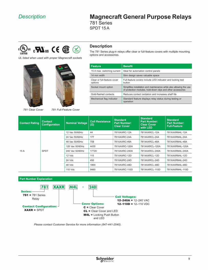
DescriptionThe 781 Series plug-in relays offer clear or full-feature covers with multiple mounting options and accessories .
Contact Rating Contact Configuration Nominal Voltage Coil Resistance
(Ω)Standard Part Number: Clear Cover
Standard Part Number: Clear Cover with LED
Standard Part Number: Full-Feature
15 A SPDT
12 Vac 50/60Hz 44 781XAXRC-12A 781XAXRCL-12A 781XAXRM4L-12A
24 Vac 50/60Hz 177 781XAXRC-24A 781XAXRCL-24A 781XAXRM4L-24A
48 Vac 50/60Hz 708 781XAXRC-48A 781XAXRCL-48A 781XAXRM4L-48A
120 Vac 50/60Hz 4430 781XAXRC-120A 781XAXRCL-120A 781XAXRM4L-120A
240 Vac 50/60Hz 17720 781XAXRC-240A 781XAXRCL-240A 781XAXRM4L-240A
12 Vdc 115 781XAXRC-12D 781XAXRCL-12D 781XAXRM4L-12D
24 Vdc 450 781XAXRC-24D 781XAXRCL-24D 781XAXRM4L-24D
48 Vdc 1800 781XAXRC-48D 781XAXRCL-48D 781XAXRM4L-48D
110 Vdc 9460 781XAXRC-110D 781XAXRCL-110D 781XAXRM4L-110D
Part Number Explanation
Series:781 = 781 Series Relay
Contact Configuration:XAXR = SPDT
Cover Options: C = Clear CoverCL = Clear Cover and LEDM4L = Locking Push Button
and LED
Coil Voltages:
Please contact Customer Service for more information (847-441-2540).
XAXR
12–240A = 12–240 VAC12–110D = 12–110 VDC
Feature Benefit15 A max . switching current Ideal for automation control panels
14 mm width Slim design saves valuable space
Clear or full-feature cover options
Full-feature covers include LED indicator and locking test button
Socket mount option Simplifies installation and maintenance while also allowing the use of protection modules, hold-down clips and other accessories
Gold-flashed contacts Reduces contact oxidation and increases shelf life
Mechanical flag indicator Standard feature displays relay status during testing or operation
Magnecraft General Purpose Relays781 SeriesSPDT 15 A
781 Full-Feature Cover
UL listed when used with proper Magnecraft sockets
781 Clear Cover

10
Specifications Magnecraft General Purpose Relays781 SeriesSPDT 15 A
SpecificationsPart Number 781XAXR
Contact CharacteristicsTerminal Style Blade
Contact Configuration SPDTMaximum Current 15 AContact Materials Silver AlloyMaximum Switching Voltage IEC: 250 Vac / 28 Vdc
UL/CSA: 300 Vac / 28 VdcRated Switching Current at Voltage (Conforming to IEC AC-1 and DC-1)
NO: 15 A at 250 Vac, NC: 7 .5 A at 250 VacNO: 15 A at 28 Vdc, NC: 7 .5 A at 28 Vdc
Rated Switching Current at Voltage (Conforming to UL)
Resistive: 15 A at 277 Vac 50 / 60 Hz, 100k cyclesResistive: 15 A at 28 Vdc, 100k cyclesMotor: 1/2 HP at 120 Vac, 1k cyclesMotor: 1 HP at 277 Vac, 1k cyclesPilot Duty: B300
Minimum Switching Requirement 100 mA at 5 Vdc
Coil CharacteristicsMaximum Operating Voltage 110% (AC / DC)
Maximum Pickup Voltage 85% (AC / DC)Drop-out Voltage Threshold 15% (AC); 10% (DC)Average Consumption Standard: 1 .6 VA (AC); 1 .1 W (DC)
With LED: 1 .9 VA (AC); 1 .4 W (DC)
General CharacteristicsElectrical Life at Rated Load 100,000 operationsMechanical Life (Unpowered) 10,000,000 operationsOperating Time (Response Time) 20 msDielectric Strength - Between Coil and Contact (AC) 2000 V(rms)Dielectric Strength - Between Poles (AC) 2000 V(rms)Dielectric Strength - Between Contacts (AC) 1500 V(rms)Ambient Air Temperature around the Device - Storage -40 to +85 °C (-40 to +185 °F)Ambient Air Temperature around the Device - Operation -40 to +55 °C (-40 to +131 °F)Vibration Resistance - Operational +/- 1 mm (10–35 Hz) and 3 g-n (35–150 Hz)Shock Resistance 15 g-nDegree of Protection (Housing Only) IP 40Weight 29 g (1 .02 oz)Agency Approvals UL with socket, UR (E43641), CE, CSA (225619), RoHS
Note: Actual product performance may vary depending on application and environmental conditions.

11
Dimensions, Wiring Diagram
Magnecraft General Purpose Relays781 SeriesSPDT 15 A
Dimensions — inches (millimeters)
Clear Cover Dimensions
Full-Feature Cover Dimensions
1.07
(27.
3)
0.55 (14.0)
1.07
(27.
3)
0.55 (14.0) 1.57 (39.8)0.21 (5.4)
1.37 (34.8)
0.28 (7.0)
0.28 (7.0)
0.02
(0.5
)0.
02 (0
.5)
0.02
(0.5
)0.
02 (0
.5)
0.19
(4.8
)
0.24
(6.0
)
0.26
(6.5
)
0.08 (2.1)
0.17 (4.2)
NEMA (IEC)
14 (A2)13 (A1)
1 (12)
9 (11)
5 (14)
Wiring Diagram

12
Description Magnecraft General Purpose Relays781 Series Accessories
DescriptionOptional sockets offer customizable, Fingersafe solutions including protection modules, hold-down clips, and ID tags . Sockets are DIN rail and panel mount compatible .
Relay AccessoriesDescription Function For Use
With Relays Pkg. Min. Standard Part Number
Socket ➊ DIN/Panel mount with screw terminals and clamping plates
781
10 70-781D5R-1A
Socket PCB-mount socket 10 70-781T-1
Adapter Mount directly to DIN rail 10 16-781C
Adapter Mount directly to panel 10 16-781C1
Socket AccessoriesDescription Function For Use With
SocketsCoil Voltage
Pkg. Min.
Standard Part Number
Metal Spring Clip ➊ Secures relay in socket 70-781D5R-1A, 70-781T-1 – 10 16-781SC
Plastic ID Hold-Down Clip ➋
Secures relay in socket and provides labeling 70-781D5R-1A – 10 16-781IDC
Extruded Aluminum DIN Rail, 39 .37'' (1000 mm) ➌
Quick installation and removal of sockets 70-781D5R-1A – 10 16-700DIN
DIN Rail End Clip ➌Holds sockets firmly in place on DIN rail – – 10 16-DCLIP-1
Small Socket Module
Protection Diode (Protects external drive circuitry from inductive voltages)
70-781D5R-1A
6 to 250 Vdc 10 70-BSMD-250
Small Socket Module ➍LED Indicator (Provides coil status at a glance) 24 Vac/Vdc 10 70-BSMLG-24
Small Socket ModuleMOV Suppressor (Protects from damaging electrical spikes)
120 Vac/Vdc 10 70-BSMM-120
24 Vac/Vdc 10 70-BSMM-24
240 Vac/Vdc 10 70-BSMM-240
Note: Use of LED socket module may increase coil power draw by up to 10%.

13
Description Magnecraft General Purpose Relays782 Power SeriesDPDT 15 A
DescriptionThe 782 Plug-in Power relays offer clear or full-feature covers with multiple mounting options and accessories .
Part Number Explanation
Series:782 = 782 Series Power Relay
Contact Configuration:XBX = DPDT
Cover Options: C = Clear CoverCL = Clear Cover and LEDCT = PC TermimalsM4L = Locking Push Button
and LED
Coil Voltages:
Please contact Customer Service for more information (847-441-2540).
6–240A = 6–240 VAC6–110D = 6–110 VDC
782 Clear Cover
Feature Benefit15 A switching current Ideal for automation control panels
Clear or full-feature cover options
Full-feature covers include LED indicator and locking test button
Socket mount option Simplifies installation and maintenance while also allowing the use of protection modules, hold-down clips and other accessories
Gold-flashed contacts Reduces contact oxidation and increases shelf life
Mechanical flag indicator Standard feature displays relay status during testing or operation
Contact Rating
Contact Configuration Nominal Voltage Coil
Resistance (Ω)Standard Part Number: Clear Cover
Standard Part Number: Clear Cover with LED
Standard Part Number: PC Mount
Standard Part Number: Full-Feature
15 A DPDT
6 Vac 50/60Hz 11 – – 782XBXCT-6A –
12 Vac 50/60Hz 44 782XBXC-12A 782XBXCL-12A 782XBXCT-12A 782XBXM4L-12A
24 Vac 50/60Hz 177 782XBXC-24A 782XBXCL-24A 782XBXCT-24A 782XBXM4L-24A
48 Vac 50/60Hz 708 782XBXC-48A 782XBXCL-48A 782XBXCT-48A 782XBXM4L-48A
120 Vac 50/60Hz 4430 782XBXC-120A 782XBXCL-120A 782XBXCT-120A 782XBXM4L-120A
240 Vac 50/60Hz 17720 782XBXC-240A 782XBXCL-240A 782XBXCT-240A 782XBXM4L-240A
6 Vdc 40 – – 782XBXCT-6D –
12 Vdc 160 782XBXC-12D 782XBXCL-12D 782XBXCT-12D 782XBXM4L-12D
24 Vdc 640 782XBXC-24D 782XBXCL-24D 782XBXCT-24D 782XBXM4L-24D
48 Vdc 2560 782XBXC-48D 782XBXCL-48D 782XBXCT-48D 782XBXM4L-48D
110 Vdc 13440 782XBXC-110D 782XBXCL-110D 782XBXCT-110D 782XBXM4L-110D
782 Full-Feature Cover
UL listed when used with proper Magnecraft sockets

14
Magnecraft General Purpose Relays782 Power SeriesDPDT 15 A
Specifications
SpecificationsPart Number 782XBXC / CL / M4L 782XBXCT
Contact CharacteristicsTerminal Style Blade PC Terminals
Contact Configuration DPDTMaximum Current 15 AContact Materials Silver AlloyMaximum Switching Voltage IEC: 250 Vac / 28 Vdc
UL/CSA: 300 Vac / 28 VdcRated Switching Current at Voltage (Conforming to IEC AC-1 and DC-1)
NO: 15 A at 250 Vac, NC: 7 .5 A at 250 VacNO: 15 A at 28 Vdc, NC: 7 .5 A at 28 Vdc
Rated Switching Current at Voltage (Conforming to UL)
Resistive: 15 A at 277 Vac 50 / 60 Hz, 100k cyclesResistive: 15 A at 28 Vdc, 100k cyclesMotor: 1/2 HP at 120 Vac, 1k cyclesMotor: 1 HP at 277 Vac, 1k cyclesPilot Duty: B300
Minimum Switching Requirement 100 mA at 5 Vdc
Coil CharacteristicsMaximum Operating Voltage 110% (AC / DC)
Maximum Pickup Voltage 85% (AC); 80% (DC)Drop-out Voltage Threshold 15% (AC); 10% (DC)Average Consumption Standard: 1 .1 VA (AC); 0 .85 W (DC)
With LED: 1 .4 VA (AC); 1 .15 W (DC)Standard: 1 .1 VA (AC); 0 .85 W (DC)With LED: 1 .45 VA (AC); 1 .2 W (DC)
General CharacteristicsElectrical Life at Rated Load 100,000 operationsMechanical Life (Unpowered) 10,000,000 operationsOperating Time (Response Time) 20 msDielectric Strength - Between Coil and Contact (AC) 2000 V(rms)Dielectric Strength - Between Poles (AC) 2000 V(rms)Dielectric Strength - Between Contacts (AC) 1500 V(rms)Ambient Air Temperature around the Device - Storage
-40 to +85 °C (-40 to +185 °F)
Ambient Air Temperature around the Device - Operation
-40 to +55 °C (-40 to +131 °F)
Vibration Resistance - Operational +/- 1 mm (10–35 Hz) and 3 g-n (35–150 Hz)Shock Resistance 15 g-nDegree of Protection (Housing Only) IP 40Weight 36 g (1 .27 oz)Agency Approvals UL with socket, UR (E43641), CE, CSA (225619), RoHS
Note: Actual product performance may vary depending on application and environmental conditions.

15
Clear Cover Dimensions
Full-Feature Cover Dimensions
1.07
[27.
3]
0.83 [21.0]
1.07
[27.
3]
0.83 [21.0] 1.54 [39.0]0.32 [8.1]
1.37 [34.8]
0.28 [7.0] 0.2 [5.0]
0.28 [7.0]
0.19
[4.7
]0.
19 [4
.7]
0.08
[2.0
]
0.02
[0.5
]0.
02 [0
.5]
0.02
[0.5
]0.
18 [4
.6]
0.23
[5.9
]
0.28
[7.1
]
0.39 [10.0]
0.08 [2.1]
0.56 [14.2]
PC Terminals Dimensions
Dimensions, Wiring Diagrams
Magnecraft General Purpose Relays782 Power SeriesDPDT 15 A
Dimensions — inches (millimeters)
Wiring Diagram
NEMA (IEC)
14 (A2)13 (A1)
1 (12)
9 (11)
5 (14)
12 (41)
8 (44)
4 (42)

16
Description Magnecraft General Purpose Relays782 Power Series Accessories
DescriptionOptional sockets offer customizable, Fingersafe solutions including protection modules, hold-down clips, and ID tags . Sockets are DIN rail and panel mount compatible .
Relay AccessoriesDescription Function For Use With
Relays Pkg. Min. Standard Part Number
Socket ➊DIN/Panel mount with screw terminals and clamping plates
782XBX
10 70-782D8-1A
Socket ➋DIN/Panel mount with screw terminals and clamping plates 10 70-459-1
Socket ➌ Quick Connect terminals for chassis mount 10 70-401-1
Socket ➍ Printed circuit terminals for PCB mount 10 70-402-1
Adapter ➎ Mount directly to panel 10 16-782C1
Adapter ➏ Mount directly to DIN rail 10 16-782C
Socket AccessoriesDescription Function For Use With
SocketsCoil Voltage
Pkg. Min.
Standard Part Number
Metal Spring Clip ➊ ➋ Secures relay in socket 70-782D8-1A, 70-459-1, 70-401-1, 70-402-1 – 10 16-1342
Plastic Hold-Down Clip ➌Secures relay in socket or ejects relay off socket 70-782D8-1A – 10 16-782PC-1
Write-on tag ➍Write-on tag for 16-782PC-1 hold-down Clip
– – 10 16-700ST-1
Plastic ID Hold-Down Clip ➎
Secures relay in socket and provides labeling
70-782D8-1A, 70-459-1, 70-401-1, 70-402-1 – 10 16-782IDC
Extruded Aluminum DIN Rail, 39 .37'' (1000 mm) ➏
Quick installation and removal of sockets 70-782D8-1A, 70-459-1 – 10 16-700DIN
DIN Rail End Clip ➏Holds sockets firmly in place on DIN rail 70-782D8-1A, 70-459-1 – 10 16-DCLIP-1
Small Socket Module
Protection Diode (Protects external drive circuitry from inductive voltages)
70-782D8-1A
6 to 250 Vdc 10 70-BSMD-250
Small Socket Module ➐LED Indicator (Provides coil status at a glance) 24 Vac/Vdc 10 70-BSMLG-24
Small Socket Module MOV Suppressor (Protects from damaging electrical spikes)
120 Vac/Vdc 10 70-BSMM-120
24 Vac/Vdc 10 70-BSMM-24
240 Vac/Vdc 10 70-BSMM-240
Note: Use of LED socket module may increase coil power draw by up to 10%.

17
Description Magnecraft General Purpose Relays783 Series3PDT 15 A
DescriptionThe 783 Series plug-in relays offer clear or full-feature covers with multiple mounting options and accessories .
Part Number Explanation
M4L = Locking Push Button and LED
CL = Clear Cover and LED
Series:783 = 783 Series Relay
Contact Configuration:XCX = 3PDT
Cover Options: C = Clear Cover
Coil Voltages:
Please contact Customer Service for more information (847-441-2540).
12–240A = 12–240 VAC12–110D = 12–110 VDC
Feature Benefit15 A max . switching current Ideal for automation panels and controls
Clear or full-feature cover options
Full-feature covers include LED indicator and locking test button
3PDT contact configuration Simultaneously control up to 3 separate circuits
Socket mount option Simplifies installation and maintenance while also allowing the use of protection modules, hold-down clips and other accessories
Gold-flashed contacts Reduces contact oxidation and increases shelf life
Mechanical flag indicator Standard feature displays relay status during testing or operation
783 Clear Cover 783 Full-Feature Cover
UL listed when used with proper Magnecraft sockets
Contact Rating Contact Configuration Nominal Voltage Coil Resistance
(Ω)Standard Part Number: Clear Cover
Standard Part Number: Clear Cover with LED
Standard Part Number: Full-Feature
15 A 3PDT
12 Vac 50/60Hz 30 783XCXC-12A 783XCXCL-12A 783XCXM4L-12A
24 Vac 50/60Hz 110 783XCXC-24A 783XCXCL-24A 783XCXM4L-24A
48 Vac 50/60Hz 460 783XCXC-48A 783XCXCL-48A 783XCXM4L-48A
120 Vac 50/60Hz 2880 783XCXC-120A 783XCXCL-120A 783XCXM4L-120A
240 Vac 50/60Hz 11300 783XCXC-240A 783XCXCL-240A 783XCXM4L-240A
12 Vdc 80 783XCXC-12D 783XCXCL-12D 783XCXM4L-12D
24 Vdc 320 783XCXC-24D 783XCXCL-24D 783XCXM4L-24D
48 Vdc 1280 783XCXC-48D 783XCXCL-48D 783XCXM4L-48D
110 Vdc 6720 783XCXC-110D 783XCXCL-110D 783XCXM4L-110D

18
Specifications Magnecraft General Purpose Relays783 Series3PDT 15 A
SpecificationsPart Number 783XCX
Contact CharacteristicsTerminal Style Blade
Contact Configuration 3PDTMaximum Current per Pole 15 AMaximum Current for Product (all poles) 30 A up to 120 Vac, 28 Vdc total;
20 A from 150 Vac to 277 Vac total;2 HP Maximum total
Contact Materials Silver AlloyMaximum Switching Voltage IEC: 250 Vac / 28 Vdc
UL/CSA: 300 Vac / 28 VdcRated Switching Current at Voltage (Conforming to IEC AC-1 and DC-1)
NO: 15 A at 250 Vac, NC: 7 .5 A at 250 VacNO: 15 A at 28 Vdc, NC: 7 .5 A at 28 Vdc
Rated Switching Current at Voltage (Conforming to UL)
Resistive: 15 A at 277 Vac 50 / 60 Hz, 100k cyclesResistive: 15 A at 28 Vdc, 100k cyclesMotor: 1/2 HP at 120 Vac, 1k cyclesMotor: 1 HP at 277 Vac, 1k cyclesPilot Duty: B300
Minimum Switching Requirement 100 mA at 5 Vdc
Coil CharacteristicsMaximum Operating Voltage 110% (AC / DC)
Maximum Pickup Voltage 85% (AC); 80% (DC)Drop-out Voltage Threshold 15% (AC); 10% (DC)Average Consumption Standard: 1 .7 VA (AC); 1 .5 W (DC)
With LED: 2 .05 VA (AC); 1 .85 W (DC)
General CharacteristicsElectrical Life at Rated Load 100,000 operationsMechanical Life (Unpowered) 10,000,000 operationsOperating Time (Response Time) 20 msDielectric Strength - Between Coil and Contact (AC) 2000 V(rms)Dielectric Strength - Between Poles (AC) 2000 V(rms)Dielectric Strength - Between Contacts (AC) 1500 V(rms)Ambient Air Temperature around the Device - Storage -40 to +85 °C (-40 to +185 °F)Ambient Air Temperature around the Device - Operation -40 to +55 °C (-40 to +131 °F)Vibration Resistance - Operational +/- 1 mm (10–35 Hz) and 3 g-n (35–150 Hz)Shock Resistance 15 g-nDegree of Protection (Housing Only) IP 40Weight 60 g (2 .12 oz)Agency Approvals UL with socket, UR (E43641), CE, CSA (225619), RoHS
Note: Actual product performance may vary depending on application and environmental conditions.

19
Dimensions — inches (millimeters)
Dimensions, Wiring Diagrams
Magnecraft General Purpose Relays783 Series3PDT 15 A
Clear Cover Dimensions
Full-Feature Cover Dimensions
1.07
[27.
3]
1.2 [30.6]
1.2 [30.6]
1.07
[27.
3]
1.54 [39.0]0.27 [6.8]
1.37 [34.8]
0.28 [7.0]
0.28 [7.0]
0.19
[4.7
]0.
19 [4
.7]
0.02
[0.5
]0.
02 [0
.5]
0.18
[4.6
]
0.23
[5.9
]
0.28
[7.1
]
0.39 [10.0]
0.39 [10.0]
0.39 [10.0]
0.79 [20.0]
Wiring Diagram
1 (12)
9 (11)
5 (14)
12 (41)
8 (44)
4 (42)2 (22)
10 (21)
6 (24)
NEMA (IEC)
14 (A2)13 (A1)
20
Description, Specifications
Magnecraft General Purpose Relays783 Series Accessories
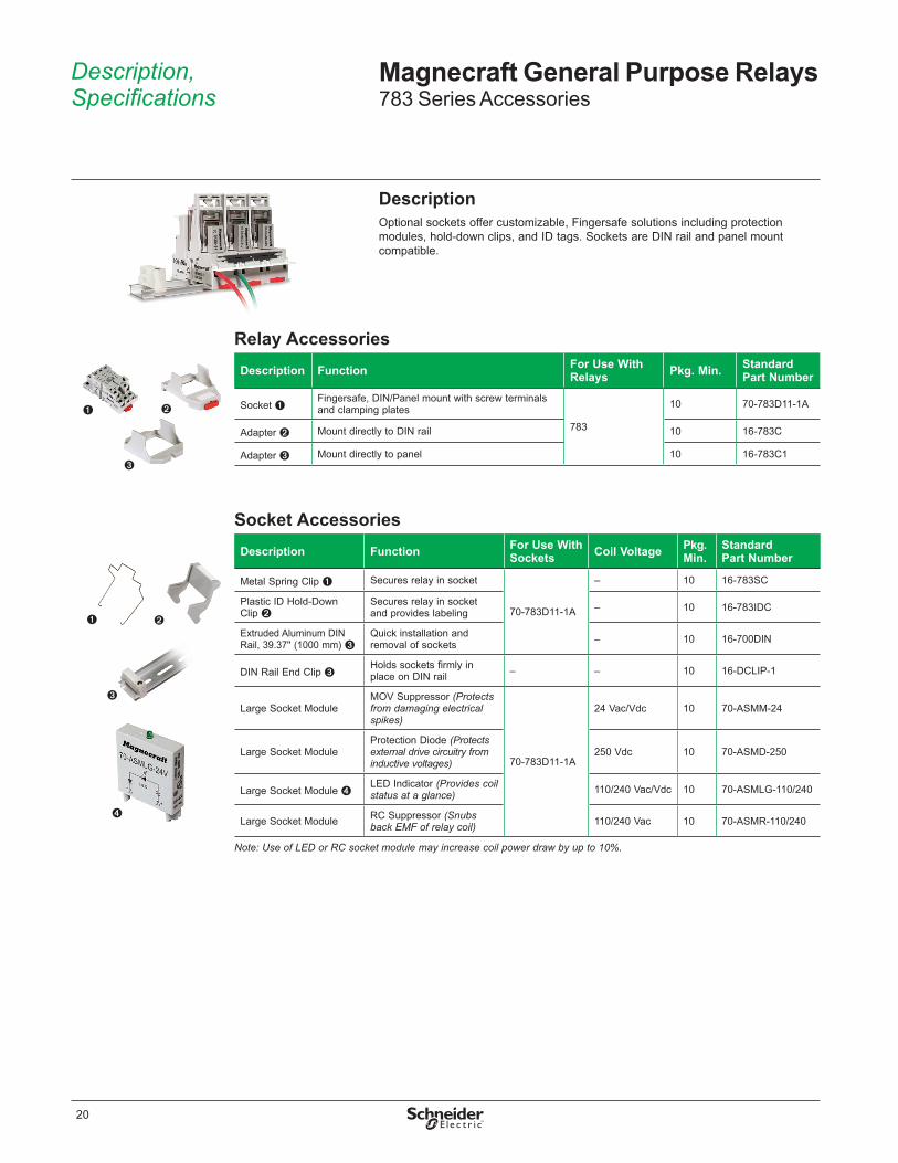
DescriptionOptional sockets offer customizable, Fingersafe solutions including protection modules, hold-down clips, and ID tags . Sockets are DIN rail and panel mount compatible .
Relay AccessoriesDescription Function For Use With
Relays Pkg. Min. Standard Part Number
Socket ➊Fingersafe, DIN/Panel mount with screw terminals and clamping plates
783
10 70-783D11-1A
Adapter ➋ Mount directly to DIN rail 10 16-783C
Adapter ➌ Mount directly to panel 10 16-783C1
Socket AccessoriesDescription Function For Use With
Sockets Coil Voltage Pkg. Min.
Standard Part Number
Metal Spring Clip ➊ Secures relay in socket
70-783D11-1A
– 10 16-783SC
Plastic ID Hold-Down Clip ➋
Secures relay in socket and provides labeling – 10 16-783IDC
Extruded Aluminum DIN Rail, 39 .37'' (1000 mm) ➌
Quick installation and removal of sockets – 10 16-700DIN
DIN Rail End Clip ➌Holds sockets firmly in place on DIN rail – – 10 16-DCLIP-1
Large Socket ModuleMOV Suppressor (Protects from damaging electrical spikes)
70-783D11-1A
24 Vac/Vdc 10 70-ASMM-24
Large Socket ModuleProtection Diode (Protects external drive circuitry from inductive voltages)
250 Vdc 10 70-ASMD-250
Large Socket Module ➍LED Indicator (Provides coil status at a glance) 110/240 Vac/Vdc 10 70-ASMLG-110/240
Large Socket Module RC Suppressor (Snubs back EMF of relay coil) 110/240 Vac 10 70-ASMR-110/240
Note: Use of LED or RC socket module may increase coil power draw by up to 10%.

21
Description Magnecraft General Purpose Relays784 Series4PDT 15 A
DescriptionThe 784 Series plug-in relays offer clear or full-feature covers with multiple mounting options and accessories .
Part Number Explanation
Series:784 = 784 Series Relay
Contact Configuration:XDX = 4PDT
Cover Options: C = Clear Cover
Coil Voltages:
M4L = Locking Push Button and LED
CL = Clear Cover and LED
Please contact Customer Service for more information (847-441-2540).
12–240A = 12–240 VAC12–110D = 12–110 VDC
Feature Benefit15 A max . switching current Ideal for automation panels and controls
Clear or full-feature cover options
Full-feature covers include LED indicator and locking test button
4PDT contact configuration Simultaneously control up to 4 separate circuits
Socket mount option Simplifies installation and maintenance while also allowing the use of protection modules, hold-down clips and other accessories
Gold-flashed contacts Reduces contact oxidation and increases shelf life
Mechanical flag indicator Standard feature displays relay status during testing or operation784 Clear Cover 784 Full-Feature Cover
UL listed when used with proper Magnecraft sockets
Contact Rating Contact Configuration Nominal Voltage Coil Resistance
(Ω)Standard Part Number: Clear Cover
Standard Part Number: Clear Cover with LED
Standard Part Number: Full-Feature
15 A 3PDT
12 Vac 50/60Hz 20 784XDXC-12A 784XDXCL-12A 784XDXM4L-12A
24 Vac 50/60Hz 80 784XDXC-24A 784XDXCL-24A 784XDXM4L-24A
48 Vac 50/60Hz 310 784XDXC-48A 784XDXCL-48A 784XDXM4L-48A
120 Vac 50/60Hz 2100 784XDXC-120A 784XDXCL-120A 784XDXM4L-120A
240 Vac 50/60Hz 8000 784XDXC-240A 784XDXCL-240A 784XDXM4L-240A
12 Vdc 76 784XDXC-12D 784XDXCL-12D 784XDXM4L-12D
24 Vdc 303 784XDXC-24D 784XDXCL-24D 784XDXM4L-24D
48 Vdc 1210 784XDXC-48D 784XDXCL-48D 784XDXM4L-48D
110 Vdc 6370 784XDXC-110D 784XDXCL-110D 784XDXM4L-110D

22
Specifications Magnecraft General Purpose Relays784 Series4PDT 15 A
SpecificationsPart Number 784XDX
Contact CharacteristicsTerminal Style Blade
Contact Configuration 4PDTMaximum Current per Pole 15 AMaximum Current for Product (all poles) 30 A up to 120 Vac, 28 Vdc total;
20 A from 150 Vac to 277 Vac total;2 HP Maximum total
Contact Materials Silver AlloyMaximum Switching Voltage IEC: 250 Vac / 28 Vdc
UL/CSA: 300 Vac / 28 VdcRated Switching Current at Voltage (Conforming to IEC AC-1 and DC-1)
NO: 15 A at 250 Vac, NC: 7 .5 A at 250 VacNO: 15 A at 28 Vdc, NC: 7 .5 A at 28 Vdc
Rated Switching Current at Voltage (Conforming to UL)
Resistive: 15 A at 277 Vac 50 / 60 Hz, 100k cyclesResistive: 15 A at 28 Vdc, 100k cyclesMotor: 1/2 HP at 120 Vac, 1k cyclesMotor: 1 HP at 277 Vac, 1k cyclesPilot Duty: B300
Minimum Switching Requirement 100 mA at 5 Vdc
Coil CharacteristicsMaximum Operating Voltage 110% (AC / DC)
Maximum Pickup Voltage 85% (AC); 80% (DC)Drop-out Voltage Threshold 15% (AC); 10% (DC)Average Consumption Standard: 2 .5 VA (AC); 1 .6 W (DC)
With LED: 2 .85 VA (AC); 1 .95 W (DC)
General CharacteristicsElectrical Life at Rated Load 100,000 operationsMechanical Life (Unpowered) 10,000,000 operationsOperating Time (Response Time) 20 msDielectric Strength - Between Coil and Contact (AC) 2000 V(rms)Dielectric Strength - Between Poles (AC) 2000 V(rms)Dielectric Strength - Between Contacts (AC) 1500 V(rms)Ambient Air Temperature around the Device - Storage -40 to +85 °C (-40 to +185 °F)Ambient Air Temperature around the Device - Operation -40 to +55 °C (-40 to +131 °F)Vibration Resistance - Operational +/- 1 mm (10–35 Hz) and 3 g-n (35–150 Hz)Shock Resistance 15 g-nDegree of Protection (Housing Only) IP 40Weight 80 g (2 .82 oz)Agency Approvals UL with socket, UR (E43641), CE, CSA (225619), RoHS
Note: Actual product performance may vary depending on application and environmental conditions.
23
Dimensions, Wiring Diagrams
Magnecraft General Purpose Relays784 Series4PDT 15 A
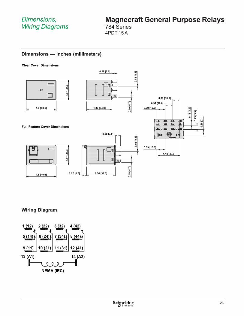
Dimensions — inches (millimeters)
Clear Cover Dimensions
Full-Feature Cover Dimensions
1.07
[27.
3]
1.6 [40.6]
1.6 [40.6]
1.07
[27.
3]
1.54 [39.0]0.27 [6.7]
1.37 [34.8]
0.28 [7.0]
0.28 [7.0]
0.19
[4.7
]0.
19 [4
.7]
0.02
[0.5
]0.
02 [0
.5]
0.18
[4.6
]
0.23
[5.9
]
0.28
[7.1
]
0.39 [10.0]
0.39 [10.0]
0.39 [10.0]
0.39 [10.0]
1.18 [30.0]
Wiring Diagram
11 (31)
7 (34)
3 (32)2 (22)1 (12)
9 (11)
5 (14)
10 (21)
6 (24)
12 (41)
8 (44)
4 (42)
NEMA (IEC)
14 (A2)13 (A1)

24
Description Magnecraft General Purpose Relays784 Series Accessories
DescriptionOptional sockets offer customizable, Fingersafe solutions including protection modules, hold-down clips, and ID tags . Sockets are DIN rail and panel mount compatible .
Relay AccessoriesDescription Function For Use With
Relays Pkg. Min. Standard Part Number
Socket ➊Fingersafe, DIN/Panel mount with screw terminals and clamping plates 784 10 70-784D14-1
Adapter ➋ DIN rail adapter 784 10 16-784C
Adapter ➌ Flange mount adapter 784 10 16-784C1
Socket AccessoriesDescription Function For Use
With Socket Coil Voltage Pkg. Min.
Standard Part Number
Metal Spring Clip ➊ Secures relay in socket
70-784D14-1
– 10 16-784SC
Plastic ID Hold-Down Clip ➋
Secures relay in socket and provides labeling – 10 16-784IDC
Extruded Aluminum DIN Rail, 39 .37'' (1000 mm) ➌
Quick installation and removal of sockets – 10 16-700DIN
DIN Rail End Clip ➌Holds sockets firmly in place on DIN rail – – 10 16-DCLIP-1
Large Socket ModuleMOV Suppressor (Protects from damaging electrical spikes)
70-784D14-1
24 Vac/Vdc 10 70-ASMM-24
Large Socket ModuleProtection Diode (Protects external drive circuitry from inductive voltages)
250 Vdc 10 70-ASMD-250
Large Socket Module ➍LED Indicator (Provides coil status at a glance) 110/240 Vac/Vdc 10 70-ASMLG-110/240
Large Socket Module RC Suppressor (Snubs back EMF of relay coil) 110/240 Vac 10 70-ASMR-110/240
Note: Use of LED or RC socket module may increase coil power draw by up to 10%.
25
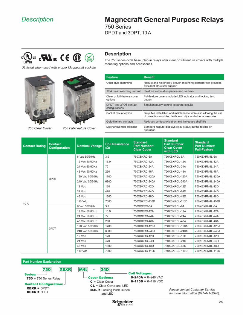
DescriptionThe 750 series octal base, plug-in relays offer clear or full-feature covers with multiple mounting options and accessories .
Part Number Explanation
Series:750 = 750 Series Relay
Contact Configuration:XBXR =XCXR =
DPDT3PDT
Cover Options: C = Clear Cover
Coil Voltages:
M4L = Locking Push Button and LED
CL = Clear Cover and LEDPlease contact Customer Service for more information (847-441-2540).
6–240A = 6–240 VAC6–110D = 6–110 VDC
Feature BenefitOctal style mounting Robust and historically-proven mounting platform that provides
excellent structural support
10 A max . switching current Ideal for automation panels and controls
Clear or full-feature cover options
Full-feature covers include LED indicator and locking test button
DPDT and 3PDT contact configurations
Simultaneously control separate circuits
Socket mount option Simplifies installation and maintenance while also allowing the use of protection modules, hold-down clips and other accessories
Gold-flashed contacts Reduces contact oxidation and increases shelf life
Mechanical flag indicator Standard feature displays relay status during testing or operation
Description Magnecraft General Purpose Relays750 SeriesDPDT and 3DPT, 10 A
750 Clear Cover 750 Full-Feature Cover
UL listed when used with proper Magnecraft sockets
Contact Rating Contact Configuration Nominal Voltage Coil Resistance
(Ω)Standard Part Number: Clear Cover
Standard Part Number: Clear Cover with LED
Standard Part Number: Full-Feature
10 A
DPDT
6 Vac 50/60Hz 3 .9 750XBXRC-6A 750XBXRCL-6A 750XBXRM4L-6A
12 Vac 50/60Hz 16 .9 750XBXRC-12A 750XBXRCL-12A 750XBXRM4L-12A
24 Vac 50/60Hz 72 750XBXRC-24A 750XBXRCL-24A 750XBXRM4L-24A
48 Vac 50/60Hz 290 750XBXRC-48A 750XBXRCL-48A 750XBXRM4L-48A
120 Vac 50/60Hz 1700 750XBXRC-120A 750XBXRCL-120A 750XBXRM4L-120A
240 Vac 50/60Hz 6800 750XBXRC-240A 750XBXRCL-240A 750XBXRM4L-240A
12 Vdc 120 750XBXRC-12D 750XBXRCL-12D 750XBXRM4L-12D
24 Vdc 470 750XBXRC-24D 750XBXRCL-24D 750XBXRM4L-24D
48 Vdc 1800 750XBXRC-48D 750XBXRCL-48D 750XBXRM4L-48D
110 Vdc 7300 750XBXRC-110D 750XBXRCL-110D 750XBXRM4L-110D
3PDT
6 Vac 50/60Hz 3 .9 750XCXRC-6A 750XCXRCL-6A 750XCXRM4L-6A
12 Vac 50/60Hz 16 .9 750XCXRC-12A 750XCXRCL-12A 750XCXRM4L-12A
24 Vac 50/60Hz 72 750XCXRC-24A 750XCXRCL-24A 750XCXRM4L-24A
48 Vac 50/60Hz 290 750XCXRC-48A 750XCXRCL-48A 750XCXRM4L-48A
120 Vac 50/60Hz 1700 750XCXRC-120A 750XCXRCL-120A 750XCXRM4L-120A
240 Vac 50/60Hz 6800 750XCXRC-240A 750XCXRCL-240A 750XCXRM4L-240A
12 Vdc 120 750XCXRC-12D 750XCXRCL-12D 750XCXRM4L-12D
24 Vdc 470 750XCXRC-24D 750XCXRCL-24D 750XCXRM4L-24D
48 Vdc 1800 750XCXRC-48D 750XCXRCL-48D 750XCXRM4L-48D
110 Vdc 7300 750XCXRC-110D 750XCXRCL-110D 750XCXRM4L-110D

26
SpecificationsPart Number 750XBXR 750XCXR
Contact CharacteristicsTerminal Style Octal Octal
Contact Configuration DPDT 3PDTMaximum Current 10 A 10 AContact Materials Silver Alloy Silver AlloyMaximum Switching Voltage IEC: 250 Vac / 28 Vdc
UL/CSA: 300 Vac / 30 VdcIEC: 250 Vac / 28 VdcUL/CSA: 300 Vac / 30 Vdc
Rated Switching Current at Voltage (Conforming to IEC AC-1 and DC-1)
NO: 10 A at 250 Vac, NC: 5 A at 250 Vac NO: 10 A at 28 Vdc, NC: 5 A at 28 Vdc
NO: 10 A at 250 Vac, NC: 5 A at 250 Vac NO: 10 A at 28 Vdc, NC: 5 A at 28 Vdc
Rated Switching Current at Voltage (Conforming to UL)
Resistive: 10 A at 277 Vac 50 / 60 Hz, 200k cycles Resistive: 10 A at 30 Vdc, 200k cycles Motor: 1/3 HP at 120 Vac, 6k cycles Motor: 1 HP at 277 Vac, 6k cycles Pilot Duty: B300, 6k cycles
Resistive: 10 A at 277 Vac 50 / 60 Hz, 200k cycles Resistive: 10 A at 30 Vdc, 200k cycles Motor: 1/3 HP at 120 Vac, 6k cycles Motor: 1 HP at 277 Vac, 6k cycles Pilot Duty: B300, 6k cycles
Minimum Switching Requirement 10 mA at 17 Vdc 10 mA at 17 Vdc
Coil CharacteristicsMaximum Operating Voltage 110% (AC / DC) 110% (AC / DC)
Maximum Pickup Voltage 85% (AC); 80% (DC) 85% (AC); 80% (DC)Drop-out Voltage Threshold 15% (AC); 10% (DC) 15% (AC); 10% (DC)Average Consumption 3 VA (AC); 1 .4 W (DC) 3 VA (AC); 1 .4 W (DC)
General CharacteristicsElectrical Life at Rated Load 100,000 operations 100,000 operationsMechanical Life 5,000,000 operations 5,000,000 operationsOperating Time (Response Time) 20 ms 20 msDielectric Strength - Between Coil and Contact (AC) 2500 V(rms) 2500 V(rms)Dielectric Strength - Between Poles (AC) 2000 V(rms) 2000 V(rms)Dielectric Strength - Between Open Contacts (AC) 1500 V(rms) 1500 V(rms)Ambient Air Temperature around the Device - Storage
-40 to +85 °C (-40 to +185°F) -40 to +85 °C (-40 to +185 °F)
Ambient Air Temperature around the Device - Operation
-40 to +55 °C (-40 to +131°F) -40 to +55 °C (-40 to +131 °F)
Vibration Resistance - Operational +/- 1 mm (10–35 Hz) and 3 g-n (35–150 Hz) +/- 1 mm (10–35 Hz) and 3 g-n (35–150 Hz)Shock Resistance 10 g-n 10 g-nDegree of Protection (Housing Only) IP 40 IP 40Weight 83 g (2 .93 oz) 83 g (2 .93 oz)Agency Approvals UL with socket, UR (E164862), CE, CSA (225619), RoHS
Note: Actual product performance may vary depending on application and environmental conditions.
Specifications Magnecraft General Purpose Relays750 SeriesDPDT and 3DPT, 10 A

27
Wiring Diagrams
Dimensions — inches (millimeters)
14
11
A1
12 22
24
A2
311
2
3
4 5
6
7
8 12
3
4
56
7
8
9
1011
11
A1
14
12
2221
24
32
34
A2
31
IECNEMA
DPDT 3PDT
Dimensions, Wiring Diagram
Magnecraft General Purpose Relays750 SeriesDPDT and 3DPT, 10 A
2.09(53)
2.2(56)
0.24(6.1)
1.38(35)
1.4(35.7)
1.4(35.7)
1.38(35)
Clear Cover Dimensions
Full-Feature Cover Dimensions

28
Description Magnecraft General Purpose Relays750 Series Accessories
DescriptionOptional sockets offer customizable, Fingersafe solutions including protection modules, hold-down clips, and ID tags . Sockets are DIN rail and panel mount compatible .
Relay AccessoriesDescription Function For Use
With RelaysPkg. Min.
Standard Part Number
Socket ➊ DIN/Panel mount, module compatible 750XBXR 10 70-750E8-1
Socket ➋DIN/Panel mount with elevator terminals, module compatible 750XBXR 10 70-750EL8-1
Socket ➌ DIN/Panel mount, module compatible 750XBXR 10 70-750DL8-1
Socket ➍ DIN/Panel mount with screw terminals and clamping plates 750XBXR 10 70-464-1
Socket ➎ Panel mount with screw terminals and clamping plates 750XBXR 10 70-169-1
Socket ➏ DIN/Panel mount with elevator terminals, module compatible 750XCXR 10 70-750E11-1
Socket ➐ DIN/Panel mount with elevator terminals 750XCXR 10 70-750EL11-1
Socket ➑ DIN/Panel mount, module compatible 750XCXR 10 70-750DL11-1
Socket ➒ DIN/Panel mount with screw terminals and clamping plates 750XCXR 10 70-465-1
Socket ➓ Panel mount with screw terminals and clamping plates 750XCXR 10 70-170-1
Socket AccessoriesDescription Function For Use With Sockets Coil
VoltagePkg. Min.
Standard Part Number
Metal Spring Clip ➊ Secures relay in socket 70-750EL8-1, 70-750E8-1, 70-750E11-1, 70-464-1 – 10 16-1351
Metal Spring Clip ➋ Secures relay in socket 70-750E8-1, 70-750DL8-1, 70-750E11-1, 70-464-1 – 10 16-1344
Metal Spring Clip ➌ Secures relay in socket 70-750DL8-1 – 10 16-1332
Plastic I .D . Tag ➍ Write-on plastic labels 70-750E8-1, 70-750EL8-1, 70-750DL8-1, 70-750E11-1, 70-750EL11, 70-750DL11-1
– 10 16-750/788FT-1
Insulated Coil Bus Jumper System ➎
Wireless socket connection – 10 16-750/788CBJ-1
Extruded Aluminum DIN Rail, 39 .37'' (1000 mm) ➏
Quick installation and removal of sockets
70-750EL8-1, 70-750E8-1, 70-750DL8-1, 70-750E11-1, 70-464-1, 70-465-1
– 10 16-700DIN
DIN Rail End Clip ➏ Plastic end clip with locking screw – – 10 16-DCLIP-1
Large Socket ModuleMOV Suppressor (Protects from damaging electrical spikes)
70-750E8-1, 70-750EL8-1, 70-750DL8-1, 70-750E11-1, 70-750EL11-1, 70-750DL11-1
24 Vac/Vdc 10 70-ASMM-24
Large Socket Module
Protection Diode (Protects external drive circuitry from inductive voltages)
250 Vdc 10 70-ASMD-250
Large Socket Module ➐LED Indicator (Provides coil status at a glance)
110/240 Vac/Vdc 10 70-ASMLG-110/240
Large Socket Module RC Suppressor (Snubs back EMF of relay coil)
110/240 Vac 10 70-ASMR-110/240
Note: Use of LED or RC socket module may increase coil power draw by up to 10%.

29
Description Magnecraft General Purpose Relays788 SeriesDPDT and 3PDT 10 A
DescriptionThe 788 Series square base, plug-in relays offer clear, full-feature, top flange, and side flange covers as well as optional sockets and accessories .
Part Number Explanation
Series:788 = 788 Series
Relay Cover Options:
C = Clear Cover
C1 = Flange CoverM4L = Locking Push Button
and LED
Coil Voltages:
Please contact Customer Service for more information (847-441-2540).
DC Switching:Blank = None69 = Magnetic
Blowout(Clear Coveronly)
Contact Configuration:XBXR =XCXR =
DPDT3PDT
CL = Clear Cover and LED
12–240A = 12–240 VAC12–110D = 12–110 VDC
Feature Benefit10 A max . switching current Ideal for automation panels and controls
Clear or full-feature cover options
Full-feature covers include LED indicator and locking test button
DPDT and 3PDT contact configurations
Simultaneously control separate circuits
Socket mount option Simplifies installation and maintenance while also allowing the use of protection modules, hold-down clips and other accessories
Gold-flashed contacts Reduces contact oxidation and increases shelf life
Mechanical flag indicator Standard feature displays relay status during testing or operation
UL listed when used with proper Magnecraft sockets
788 Clear Cover 788 Full-Feature Cover
Contact Rating
Contact Configuration Nominal Voltage Coil
Resistance (Ω)Standard Part Number: Clear Cover
Standard Part Number: Clear Cover with LED
Standard Part Number: Flange Mount
Standard Part Number: Full-Feature
10 A
DPDT
12 Vac 50/60Hz 16 .9 788XBXRC-12A 788XBXRCL-12A 788XBXRC1-12A 788XBXRM4L-12A
24 Vac 50/60Hz 72 788XBXRC-24A 788XBXRCL-24A 788XBXRC1-24A 788XBXRM4L-24A
48 Vac 50/60Hz 290 788XBXRC-48A 788XBXRCL-48A 788XBXRC1-48A 788XBXRM4L-48A
120 Vac 50/60Hz 1700 788XBXRC-120A 788XBXRCL-120A 788XBXRC1-120A 788XBXRM4L-120A
240 Vac 50/60Hz 6800 788XBXRC-240A 788XBXRCL-240A 788XBXRC1-240A 788XBXRM4L-240A
12 Vdc 120 788XBXRC-12D 788XBXRCL-12D 788XBXRC1-12D 788XBXRM4L-12D
24 Vdc 470 788XBXRC-24D 788XBXRCL-24D 788XBXRC1-24D 788XBXRM4L-24D
48 Vdc 1800 788XBXRC-48D 788XBXRCL-48D 788XBXRC1-48D 788XBXRM4L-48D
110 Vdc 7300 788XBXRC-110D 788XBXRCL-110D 788XBXRC1-110D 788XBXRM4L-110D
3PDT
12 Vac 50/60Hz 16 .9 788XCXRC-12A 788XCXRCL-12A 788XCXRC1-12A 788XCXRM4L-12A
24 Vac 50/60Hz 72 788XCXRC-24A 788XCXRCL-24A 788XCXRC1-24A 788XCXRM4L-24A
48 Vac 50/60Hz 290 788XCXRC-48A 788XCXRCL-48A 788XCXRC1-48A 788XCXRM4L-48A
120 Vac 50/60Hz 1700 788XCXRC-120A 788XCXRCL-120A 788XCXRC1-120A 788XCXRM4L-120A
240 Vac 50/60Hz 6800 788XCXRC-240A 788XCXRCL-240A 788XCXRC1-240A 788XCXRM4L-240A
12 Vdc 120 788XCXRC-12D 788XCXRCL-12D 788XCXRC1-12D 788XCXRM4L-12D
24 Vdc 470 788XCXRC-24D 788XCXRCL-24D 788XCXRC1-24D 788XCXRM4L-24D
48 Vdc 1800 788XCXRC-48D 788XCXRCL-48D 788XCXRC1-48D 788XCXRM4L-48D
110 Vdc 7300 788XCXRC-110D 788XCXRCL-110D 788XCXRC1-110D 788XCXRM4L-110D
Note: Magnetic blowout versions are also available with an added contact rating of 3 A at 150 Vdc. Please refer to the Part Number Explanation shown below.

30
Specifications Magnecraft General Purpose Relays788 SeriesDPDT and 3PDT 10 A
SpecificationsPart Number 788XBXR/XCXR
Contact CharacteristicsTerminal Style Blade
Contact Configuration DPDT/3PDTMaximum Current 10 AContact Materials Silver AlloyMaximum Switching Voltage IEC: 250 Vac / 28 Vdc
UL/CSA: 300 Vac / 30 VdcRated Switching Current at Voltage (Conforming to IEC AC-1 and DC-1)
NO: 10 A at 250 Vac, NC: 5 A at 250 Vac NO: 10 A at 28 Vdc, NC: 5 A at 28 Vdc
Rated Switching Current at Voltage (Conforming to UL)
Resistive: 10 A at 277 Vac 50 / 60 Hz, 200k cycles Resistive: 10 A at 30 Vdc, 200k cycles Motor: 1/3 HP at 120 Vac, 6k cycles Motor: 1 HP at 277 Vac, 6k cycles Pilot Duty: B300, 6k cycles
Rated Current with Magnetic Blowout (Code 69) UL: 3 A at 150 Vdc (DPDT only), 6k cyclesMinimum Switching Requirement 10 mA at 17 Vdc
Coil CharacteristicsMaximum Operating Voltage 110% (AC / DC)
Maximum Pickup Voltage 85% (AC); 80% (DC)Drop-out Voltage Threshold 15% (AC); 10% (DC)Average Consumption 3 VA (AC); 1 .4 W (DC)
General CharacteristicsElectrical Life at Rated Load 100,000 operationsMechanical Life (Unpowered) 5,000,000 operationsOperating Time (Response Time) 20 msDielectric Strength - Between Coil and Contact (AC) 2500 V(rms)Dielectric Strength - Between Poles (AC) 2000 V(rms)Dielectric Strength - Between Open Contacts (AC) 1500 V(rms)Ambient Air Temperature around the Device - Storage
-40 to +85 °C (-40 to +185 °F)
Ambient Air Temperature around the Device - Operation
-40 to +55 °C (-40 to +131 °F)
Vibration Resistance - Operational +/- 1 mm (10–35 Hz) and 3 g-n (35–150 Hz)Shock Resistance 10 g-nDegree of Protection (Housing Only) IP 40Weight 83 g (2 .93 oz)Agency Approvals UL with socket, UR (E164862), CE, CSA (225619), RoHS
Note: Actual product performance may vary depending on application and environmental conditions.

31
Dimensions, Wiring Diagrams
Magnecraft General Purpose Relays788 SeriesDPDT and 3PDT 10 A
Dimensions — inches (millimeters)
Wiring Diagrams
BAA1 A2
711
34
5
322
AA1
711
14
4121
BABA2 A1 A2
921
24
711
6223
4121
9831 21
34 24
532
622
2 3
14IEC
NEMA
SPDT DPDT 3PDT
1.97(50)
0.24(6.1) 1.38
(35)
1.4(35.7)
2.09(53)
1.38(35)
1.4(35.7)
0.04(1.0)
1.9(48.2)
Clear Cover Dimensions
Full-Feature Cover Dimensions
Side Flange Cover Dimensions
1.38(35)
1.4(35.7)
2.37(60.3)
2.77(70.3)
32
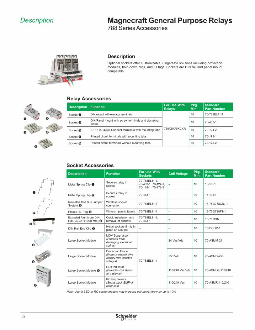
Description Magnecraft General Purpose Relays788 Series Accessories
DescriptionOptional sockets offer customizable, Fingersafe solutions including protection modules, hold-down clips, and ID tags . Sockets are DIN rail and panel mount compatible .
Relay AccessoriesDescription Function For Use With
RelaysPkg. Min.
Standard Part Number
Socket ➊ DIN mount with elevator terminals
788XBXR/XCXR
10 70-788EL11-1
Socket ➋DIN/Panel mount with screw terminals and clamping plates 10 70-463-1
Socket ➌ 0 .187 in . Quick Connect terminals with mounting tabs 10 70-124-2
Socket ➍ Printed circuit terminals with mounting tabs 10 70-178-1
Socket ➎ Printed circuit terminals without mounting tabs 10 70-178-2
Socket AccessoriesDescription Function For Use With
Sockets Coil Voltage Pkg. Min.
Standard Part Number
Metal Spring Clip ➊Secures relay in socket
70-788EL11-1, 70-463-1, 70-124-1, 70-178-1, 70-178-2
– 10 16-1351
Metal Spring Clip ➋Secures relay in socket 70-463-1 – 10 16-1344
Insulated Coil Bus Jumper System ➌
Wireless socket connection 70-788EL11-1 – 10 16-750/788CBJ-1
Plastic I .D . Tag ➍ Write-on plastic labels 70-788EL11-1 – 10 16-750/788FT-1
Extruded Aluminum DIN Rail, 39 .37'' (1000 mm) ➎
Quick installation and removal of sockets
70-788EL11-1, 70-463-1 – 10 16-700DIN
DIN Rail End Clip ➎Holds sockets firmly in place on DIN rail – – 10 16-DCLIP-1
Large Socket Module
MOV Suppressor (Protects from damaging electrical spikes)
70-788EL11-1
24 Vac/Vdc 10 70-ASMM-24
Large Socket Module
Protection Diode (Protects external drive circuitry from inductive voltages)
250 Vdc 10 70-ASMD-250
Large Socket Module ➏LED Indicator (Provides coil status at a glance)
110/240 Vac/Vdc 10 70-ASMLG-110/240
Large Socket Module RC Suppressor (Snubs back EMF of relay coil)
110/240 Vac 10 70-ASMR-110/240
Note: Use of LED or RC socket module may increase coil power draw by up to 10%.

33
Description Magnecraft General Purpose Relays782H Hazardous Location Series4PDT 3 A and 5 A
DescriptionThe hermetically sealed 782H Series relays comply with UL Class I Division 2 requirements for use in hazardous locations .
Contact Rating Contact Configuration Nominal Voltage Coil Resistance (Ω) Standard Part Number
3 A 4PDT
120 Vac 50/60 Hz 3900 782XDXH10-120A
12 Vdc 160 782XDXH10-12D
24 Vdc 650 782XDXH10-24D
110 Vdc 11000 782XDXH10-110D
5 A 4PDT
120 Vac 50/60 Hz 3900 782XDXH21-120A
12 Vdc 160 782XDXH21-12D
24 Vdc 650 782XDXH21-24D
Part Number Explanation
Series:782 = 782H Series Hazardous Location Relay
Contact Configuration:XDXH = 4PDT, Hermetic
Coil Voltages:
Please contact Customer Service for more information (847-441-2540).
Contact Code:10 = 3A Fine Silver, Gold Diffused 21 = 5A Silver Alloy
24–240A = 24–240 VAC12–110D = 12–110 VDC
Feature BenefitHermetically sealed Complies with UL Class I Division 2 for Hazardous Locations
Groups A, B, C, and D; sealed for wash down conditions
3 A / 5 A max . switching current
Ideal for automation and control applications
4PDT contact configuration Simultaneously control up to 4 separate circuits
Screw mount options Allows for direct mounting
Socket mount option Simplifies installation and maintenance while also allowing the use of protection modules, hold-down clips and other accessories
Gold-flashed contacts Reduces contact oxidation and increases shelf life782H Hazardous Location Relay
UL listed when used with proper Magnecraft sockets
34
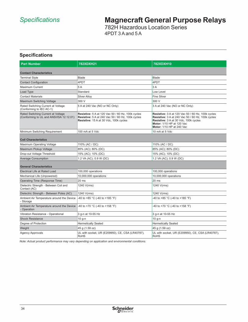
Specifications Magnecraft General Purpose Relays782H Hazardous Location Series4PDT 3 A and 5 A
SpecificationsPart Number 782XDXH21 782XDXH10
Contact CharacteristicsTerminal Style Blade BladeContact Configuration 4PDT 4PDTMaximum Current 5 A 3 ALoad Type Standard Low LevelContact Materials Silver Alloy Fine SilverMaximum Switching Voltage 300 V 300 VRated Switching Current at Voltage (Conforming to IEC AC-1)
5 A at 240 Vac (NO or NC Only) 3 A at 240 Vac (NO or NC Only)
Rated Switching Current at Voltage (Conforming to UL and ANSI/ISA 12 .12 .01)
Resistive: 5 A at 120 Vac 50 / 60 Hz, 100k cyclesResistive: 5 A at 240 Vac 50 / 60 Hz, 100k cyclesResistive: 15 A at 30 Vdc, 100k cycles
Resistive: 3 A at 120 Vac 50 / 60 Hz, 100k cyclesResistive: 3 A at 240 Vac 50 / 60 Hz, 100k cyclesResistive: 3 A at 30 Vdc, 100k cyclesMotor: 1/10 HP at 120 VacMotor: 1/10 HP at 240 Vac
Minimum Switching Requirement 100 mA at 5 Vdc 10 mA at 5 Vdc
Coil CharacteristicsMaximum Operating Voltage 110% (AC / DC) 110% (AC / DC)Maximum Pickup Voltage 85% (AC); 80% (DC) 85% (AC); 80% (DC)Drop-out Voltage Threshold 15% (AC); 10% (DC) 15% (AC); 10% (DC)Average Consumption 1 .2 VA (AC); 0 .9 W (DC) 1 .2 VA (AC); 0 .9 W (DC)
General CharacteristicsElectrical Life at Rated Load 100,000 operations 100,000 operationsMechanical Life (Unpowered) 10,000,000 operations 10,000,000 operationsOperating Time (Response Time) 20 ms 20 msDielectric Strength - Between Coil and Contact (AC)
1240 V(rms) 1240 V(rms)
Dielectric Strength - Between Poles (AC) 1240 V(rms) 1240 V(rms)Ambient Air Temperature around the Device - Storage
-40 to +85 °C (-40 to +185 °F) -40 to +85 °C (-40 to +185 °F)
Ambient Air Temperature around the Device - Operation
-40 to +70 °C (-40 to +158 °F) -40 to +70 °C (-40 to +158 °F)
Vibration Resistance - Operational 3 g-n at 10-55 Hz 3 g-n at 10-55 HzShock Resistance 10 g-n 10 g-nDegree of Protection Hermetically Sealed Hermetically SealedWeight 45 g (1 .59 oz) 45 g (1 .59 oz)Agency Approvals UL with socket, UR (E209950), CE, CSA (LR40787),
RoHSUL with socket, UR (E209950), CE, CSA (LR40787), RoHS
Note: Actual product performance may vary depending on application and environmental conditions.

35
Dimensions, Wiring Diagram
Magnecraft General Purpose Relays782H Hazardous Location Series4PDT 3 A and 5 A
Wiring Diagrams
A1
13
11 21 31
A2
14
41
3212
342414
9 10 11
5 6 7
22
44
12
8
421 2 3 4
IECNEMA
4PDT
0.312 (7.92) LONG#3-48 THREAD
782H
1.28(32.54)
1.16(29.36)
0.25(6.35)
0.91(23.1)
0.02(0.508)
Dimensions — inches (millimeters)

36
Description Magnecraft General Purpose Relays782H Hazardous Location Series Accessories
DescriptionOptional sockets offer customizable, Fingersafe solutions including protection modules, hold-down clips, and ID tags . Sockets are DIN rail and panel mount compatible .
Relay AccessoriesDescription Function For Use
With RelaysPkg. Min.
Standard Part Number
Socket ➊ DIN/Panel mount with screw terminals and clamping plates 782XDXH 10 70-782D14-1
Socket ➋ DIN/Panel mount with elevator terminals 782XDXH 10 70-782EL14-1
Socket ➌ DIN/Panel mount with rising elevator box terminals 782XDXH 10 70-782E14-1
Socket ➍DIN/Panel mount with screw terminals and clamping plates 782XDXH 10 70-461-1
Socket ➎ Solder Terminals for Chassis Mount 782XDXH 10 70-378-1
Socket ➏ Printed circuit terminals for PCB mount 782XDXH 10 70-379-1
Socket AccessoriesDescription Function For Use With
SocketsCoil Voltage
Pkg. Min.
Standard Part Number
Metal Spring Clip ➊ Secures relay in socket
70-782D14-1, 70-782E14-1, 70-782EL14-1, 70-461-1, 70-378-1, 70-379-1
– 10 16-1342
Plastic I .D . Tag ➋ Write-on plastic labels 70-782E14-1, 70-782EL14-1 – 10 16-782FT-1
Insulated Coil Bus Jumper System ➌
Wireless socketconnection 70-782EL14-1 – 10 16-782CBJ-1
Extruded Aluminum DIN Rail, 39 .37'' (1000 mm) ➍
Quick installation and removal of sockets
70-782D14-1, 70-782EL14-1, 70-782E14-1
– 10 16-700DIN
DIN Rail End Clip ➍Holds sockets firmly in place on DIN rail – – 10 16-DCLIP-1
Small Socket Module Protection Diode (Protects external drive circuitry from inductive voltages)
70-782D14-1, 70-782EL14-1, 70-782E14-1
6 to 250 Vdc 10 70-BSMD-250
Small Socket Module ➎LED Indicator (Provides coil status at a glance) 24 Vac/Vdc 10 70-BSMLG-24
Small Socket ModuleMOV Suppressor (Protects from damaging electrical spikes)
120 Vac/Vdc 10 70-BSMM-120
24 Vac/Vdc 10 70-BSMM-24
240 Vac/Vdc 10 70-BSMM-240
Note: Use of LED socket module may increase coil power draw by up to 10%.

37
Description Magnecraft General Purpose Relays750H Hazardous Location SeriesDPDT, 3PDT 12 A
DescriptionThe hermetically sealed 750H Series relays comply with UL Class I Division 2 requirements for use in hazardous locations .
Contact Rating Contact Configuration Nominal Voltage Coil Resistance (Ω) Standard Part Number
12 A
DPDT
24 Vac 50/60 Hz 72 750XBXH-24A
120 Vac 50/60 Hz 1700 750XBXH-120A
12 Vdc 120 750XBXH-12D
24 Vdc 470 750XBXH-24D
110 Vdc 10000 750XBXH-110D
3PDT
24 Vac 50/60 Hz 72 750XCXH-24A
120 Vac 50/60 Hz 1700 750XCXH-120A
24 Vdc 470 750XCXH-24D
110 Vdc 10000 750XCXH-110D
Part Number Explanation
Series:750 = 750H Hazardous Location Series Relay
Contact Configuration:XBXH = DPDT, HermeticXCXH = 3PDT, Hermetic
Coil Voltages:
Please contact Customer Service for more information (847-441-2540).
24–240A = 24–240 VAC12–110D = 12–110 VDC
Feature BenefitHermetically sealed Complies with UL Class I Division 2 for Hazardous Locations
Groups A, B, C, and D; sealed for wash down conditions
Octal style mounting Robust and historically-proven mounting platform that provides excellent structural support
12 A max . switching current Ideal for automation and control applications
DPDT and 3PDT contact configuration
Simultaneously control separate circuits
Socket mount option Simplifies installation and maintenance while also allowing the use of protection modules, hold-down clips and other accessories750H Hazardous
Location Relay
UL listed when used with proper Magnecraft sockets

38
Magnecraft General Purpose Relays750H Hazardous Location SeriesDPDT, 3PDT 12 A
Specifications
Specifications (UL 508) Part Number 750XBXH 750XCXH
Contact CharacteristicsTerminal Style Octal Octal
Contact Configuration DPDT 3PDTMaximum Current 12 A 12 ALoad Type Standard StandardContact Materials Silver Alloy Silver AlloyMaximum Switching Voltage 300 V 300 VRated Switching Current at Voltage (Conforming to UL and ANSI/ISA 12 .12 .01)
Resistive: 12 A at 120 Vac 50/60 Hz; 12 A at 240 Vac 50/60 Hz; 12 A at 28 VdcMotor: 1/2 HP at 240 Vac 50/60 Hz; 1/3 HP at 120 Vac 50/60 HzPilot Duty: B300
Resistive: 12 A at 120 Vac 50/60 Hz; 12 A at 240 Vac 50/60 Hz; 12 A at 28 VdcMotor: 1/2 HP at 240 Vac 50/60 Hz; 1/3 HP at 120 Vac 50/60 HzPilot Duty: B300
Minimum Switching Requirement 100 mA at 5 Vdc 100 mA at 5 Vdc
Coil CharacteristicsMaximum Operating Voltage 110% (AC / DC) 110% (AC / DC)
Maximum Pickup Voltage 85% (AC); 80% (DC) 85% (AC); 80% (DC)Drop-out Voltage Threshold 15% (AC); 10% (DC) 15% (AC); 10% (DC)Average Consumption 1 .2 VA (AC); 0 .9 W (DC) 2 VA (AC); 1 .2 W (DC)
General CharacteristicsElectrical Life at Rated Load 100,000 operations 100,000 operationsMechanical Life (Unpowered) 10,000,000 operations 10,000,000 operationsOperating Time (Response Time) 20 ms 20 msDielectric Strength - Between Coil and Contact (AC) 1500 V(rms) 1500 V(rms)Dielectric Strength - Between Poles (AC) 1500 V(rms) 1500 V(rms)Ambient Air Temperature around the Device - Storage
-40 to +85 °C (-40 to 185 °F) -40 to +85 °C (-40 to 185 °F)
Ambient Air Temperature around the Device - Operation
-40 to +55 °C (-40 to 131 °F) -40 to +55 °C (-40 to 131 °F)
Vibration Resistance - Operational 3 g-n at 10-55 Hz 3 g-n at 10-55 HzShock Resistance 10 g-n 10 g-nDegree of Protection Hermetically Sealed Hermetically SealedWeight 130 g (4 .59 oz) 130 g (4 .59 oz)Agency Approvals UL with socket, UR (E209950), RoHS UL with socket, UR (E209950), RoHS
Note: Actual product performance may vary depending on application and environmental conditions.

39
750H
2.1(50.3)
1.61 MAX(40.9)
1.44 MAX(36.6)
Dimensions, Wiring Diagrams
Magnecraft General Purpose Relays750H Hazardous Location SeriesDPDT, 3PDT 12 A
Dimensions — inches (millimeters)
Wiring Diagrams
DPDT 3PDT
14
11
A1
12 22
24
A2
311
2
3
4 5
6
7
8 1
2
3
4
56
7
8
9
10
1111
A1
14
12
2221
24
32
34
A2
31
IECNEMA

40
Description Magnecraft General Purpose Relays750H Hazardous Location Series Accessories
DescriptionOptional sockets offer customizable, Fingersafe solutions including protection modules, hold-down clips, and ID tags . Sockets are DIN rail and panel mount compatible .
Relay AccessoriesDescription Function For Use
With Relays Pkg. Min. Standard Part Number
Socket ➊ DIN/Panel Mount with Screw Terminals 750XBXH 10 70-750DL8-1
Socket ➋DIN/Panel mount with elevator terminals, module compatible 750XBXH 10 70-750E8-1
Socket ➌DIN/Panel mount with screw terminals and clamping plates 750XBXH 10 70-464-1
Socket ➍ Panel mount with screw terminals and clamping plates 750XBXH 10 70-169-1
Socket ➎ DIN/Panel Mount 750XCXH 10 70-750DL11-1
Socket ➏ DIN/Panel mount with elevator terminals 750XCXH 10 70-750E11-1
Socket ➐DIN/Panel mount with screw terminals and clamping plates 750XCXH 10 70-465-1
Socket ➑ Panel mount with screw terminals and clamping plates 750XCXH 10 70-170-1
Socket AccessoriesDescription Function For Use With
Sockets Coil Voltage Pkg. Min.
Standard Part Number
Metal Spring Clip ➊ Secures relay in socket
70-750DL8-1, 70-750E8-1, 70-464-1, 70-750E11-1, 70-750DL11-1, 70-465-1
– 10 16-1351
Plastic I .D . Tag ➋ Write-on plastic labels 70-750E8-1, 70-750E11-1 – 10 16-750/788FT-1
Insulated Coil Bus Jumper System ➌
Wireless SocketConnection
70-750DL8-1, 70-750DL11-1 – 10 16-750/788CBJ-1
Extruded Aluminum DIN Rail, 39 .37'' (1000 mm) ➍
Quick installation and removal of sockets
70-750DL8-1, 70-750E8-1, 70-464-1, 70-750E11-1, 70-750DL11-1, 70-465-1
– 10 16-700DIN
DIN Rail End Clip ➍Holds sockets firmly in place on DIN rail – – 10 16-DCLIP-1
Large Socket Module
MOV Suppressor (Protects from damaging electrical spikes)
70-750DL8-1, 70-750E8-1, 70-750E11-1, 70-750DL11-1
24 Vac/Vdc 10 70-ASMM-24
Large Socket Module
Protection Diode (Protects external drive circuitry from inductive voltages)
250 Vdc 10 70-ASMD-250
Large Socket Module ➎
LED Indicator (Provides coil status at a glance)
110/240 Vac/Vdc 10 70-ASMLG-110/240
Large Socket Module
RC Suppressor (Snubs back EMF of relay coil) 110/240 Vac 10 70-ASMR-110/240
Note: Use of LED or RC socket module may increase coil power draw by up to 10%.

41
Contents Magnecraft General Purpose RelaysSockets and Mounting Adapters
b Socket Specifications . . . . . . . . . . . . . . . . . . . . . . . . . . . . . . . . . . . . . . . . . . . . . . .42
b Mounting Adapter Specifications . . . . . . . . . . . . . . . . . . . . . . . . . . . . . . . . . . . . . .65
The following relay/socket combinations comprise a UL Listed assembly when used with each other . This added benefit allows for easier installation as there are no end-use evaluations required when using Magnecraft relays or sockets with third party components .
UL Listed Relay/Socket CombinationsMating Relay(s) Number of Socket Pins Socket Part Number
781 5 70-781D5R-1A
782 870-782D8-1A
70-459-1
792XBX 8 70-782EL8-1
792XDX 14
70-782D14-1
70-782E14-1
70-782EL14-1
70-461-1
783 11 70-783D11-1A
784 14 70-784D14-1
750
8
70-464-1
70-750E8-1
70-750EL8-1
70-750DL8-1
11
70-465-1
70-750E11-1
70-750EL11-1
70-750DL11-1
788 1170-463-1
70-788EL11-1
782H 14
70-782EL14-1
70-782E14-1
70-782D14-1
70-461-1
750H
870-464-1
70-750E8-1
1170-465-1
70-750E11-1
783XCX Relay with70-783D11-1A Socket and 16-783SC Spring Clip

42
Specifications, Dimensions, Wiring Diagrams
Magnecraft General Purpose RelaysSocket Specifications70-124-2
Socket Specifications Part Number 70-124-2
Contact Configuration 3PDTNumber of Terminals 11Mounting Style Panel / ChassisCurrent Rating 15 ANominal Voltage Rating 300 VStorage Temperature Range -40 to +105 °C (-40 to +221 °F)Operating Temperature Range -40 to +55 °C (-40 to +131 °F)Protection Category (Fingersafe) IP 20Internal Metal Tracks Copper Alloy, Zinc PlatedScrew Terminals Copper Alloy, Zinc PlatedScrew Style –Screw Size –Maximum Screw Torque –Terminal Connection SolderTerminal Layout MixMaximum Wire Size Solid Cu: (Output) 16 AWG,1 .0 mm²; Stranded Cu: (Output) 16 AWG,1 .0 mm²DIN Rail Mounting, EN 60715 –Chassis Mount Screw Torque –Flammability Rating 94V-0Weight 12 .1 g (0 .43 oz)Agency Approvals UL (E70550), CE, CSA (LR40787), RoHS
70-124-2
(7.54)
2.03(51.0)
(2.5)0.5
1.37(34.7)
(42.8)1.68
1.5(38.1)
0.165 DIA. (4.19) 2 HOLES
0.297
0.02(0.508)
(31.7)1.25
(22.2)(5.28)0.28
1.39(35.4)
1.27(32.3)
1.68(42.6)
CHASSIS CUTOUTRECOMMENDED
0.870.156 (3.9)DIA HOLES
3/16 Q.C. TYPE TERMINALS 0.187 (4.7)
0.63(16.17)
(6.09)0.24
0.29(7.54)
(34.7)1.37
0.18(4.7) TYP.
70-124-2
COM
N.O.
N.C.
INPUTBAA1 A2
711
4121
9831 21
34 245
326
222 3
14
IECNEMA
70-124-2
Dimensions — inches (millimeters) Wiring Diagram

43
Specifications, Dimensions, Wiring Diagrams
Magnecraft General Purpose RelaysSocket Specifications70-169-1 and 70-170-1
Socket SpecificationsPart Number 70-169-1 70-170-1
Contact Configuration DPDT 3PDTNumber of Terminals 8 11Mounting Style Panel PanelCurrent Rating 15 A 15 ANominal Voltage Rating 300 V 300 VStorage Temperature Range -40 to +105 °C (-40 to +221 °F) -40 to +105 °C (-40 to +221 °F)Operating Temperature Range -40 to +55 °C (-40 to +131 °F) -40 to +55 °C (-40 to +131 °F)Protection Category (Fingersafe) – –Internal Metal Tracks Copper Alloy, Zinc Plated Copper Alloy, Zinc Plated
Screw Terminals Steel, Zinc Plated Steel, Zinc PlatedScrew Style Combination Head Combination HeadScrew Size M3 .5 mm M3 .5 mmMaximum Screw Torque 9 Lb-in / 1 .0 N•m 9 Lb-in / 1 .0 N•mTerminal Connection Screw Clamping Screw ClampingTerminal Layout Mix MixMaximum Wire Size Solid Cu: 12/14 (2) AWG, 4/2 .5 (2) mm²
Stranded Cu: 12/14 (2) AWG, 4/2 .5 (2) mm²Solid Cu: 12/14 (2) AWG, 4/2 .5 (2) mm² Stranded Cu: 12/14 (2) AWG, 4/2 .5 (2) mm²
DIN Rail Mounting, EN 60715 35 mm 35 mmChassis Mount Screw Torque 7 Lb-in / 0 .8 N•m 7 Lb-in / 0 .8 N•mFlammability Rating 94V-0 94V-0Weight 57 g (2 .01 oz) 57 g (2 .01 oz)Agency Approvals UL (E70550), CE, CSA (LR97899), RoHS UL (E70550), CE, CSA (LR97899), RoHS
Dimensions — inches (millimeters)70-169-1
76
8 1
23
5 4
0.17 DIA. (4.3)
0.25(6.3)
0.625(16.0)
2.0(50.0)1.68
(42.8)
2.25(57.0)
1.12 (28.0)
70-170-1
0.17 DIA. (4.3)
7 6
11
98
10
1
23
5
4
2.5(64.0)
2.2(56.0)
2.59(65.0)
1.29(32.0)
0.25(6.3)
0.629(16.0)
70-169-1
3
4
2
1
6
5
8
7
24
A2
14
1222
A1
111
2
5 4
3
7
6
218
INPUT INPUT
IECNEMA
70-170-1
5
11 1
39
10 2
48
67 4
3
8
91434
1257
6 222421
32
210111 A1A21131INPUT INPUT
IECNEMA
Wiring Diagrams

44
Magnecraft General Purpose RelaysSocket Specifications70-178-1 and 70-178-2
Socket SpecificationsPart Number 70-178-1 70-178-2
Contact Configuration 3PDT 3PDTNumber of Terminals 11 11Mounting Style Panel / PCB PCBCurrent Rating 15 A 15 ANominal Voltage Rating 300 V 300 VStorage Temperature Range -40 to +105 °C (-40 to +221 °F) -40 to +105 °C (-40 to +221 °F)Operating Temperature Range -40 to +55 °C (-40 to +131 °F) -40 to +55 °C (-40 to +131 °F)Protection Category (Fingersafe) IP 20 IP 20Internal Metal Tracks Copper Alloy, Zinc Plated Copper Alloy, Zinc PlatedScrew Terminals Copper Alloy, Zinc Plated Copper Alloy, Zinc PlatedScrew Style – –Screw Size – –Maximum Screw Torque – –Terminal Connection PCB PCBTerminal Layout Mix MixMaximum Wire Size Solid Cu: (Output): 16 AWG, 1 .0 mm²
Stranded Cu: (Output): 16 AWG, 1 .0 mm²Solid Cu: (Output): 16 AWG, 1 .0 mm²Stranded Cu: (Output): 16 AWG, 1 .0 mm²
DIN Rail Mounting, EN 60715 – –Chassis Mount Screw Torque – –Flammability Rating 94V-0 94V-0Weight 12 .1 g (0 .43 oz) 12 .1 g (0 .43 oz)Agency Approvals UL (E70550), CE, CSA (LR40787), RoHS UL (E70550), CE, CSA (LR40787), RoHS
Dimensions — inches (millimeters)
Wiring Diagram
70-178-270-178-1
(8.05)
0.055 - 0.062(1.39 - 1.57)
0.317 0.175
0.156(3.96)
(4.44)
1.5(38.1)(7.54)
2.03(51)
(2.5)0.5
1.37(34.7)
(42.8)1.68
0.165 DIA. (4.19) 2 HOLES
0.297
0.02(0.508)
(31.7)1.25
(7.54)0.297
(42.6)1.68 4 65
A
7
B
98
0.546
(5.5)0.218
(13.8) 0.844(21.4)
11 PLACES0.078 (1.98) DIA.
0.156 (3.9) DIA. 2 HOLES
RECOMMENDED CIRCUIT BOARD LAYOUT FOR 70-178-1 & 70-178-2
BOTTOM VIEW
1 32
0.875(22.2)
(11)0.43
(11)0.431.37
(34.7)
1.5(38.1)
0.317
(1.39 - 1.57)0.055 - 0.062
(8.05)(4.44)
(3.96)0.156
0.175
(0.89)0.035
70-178-1 & 70-178-2
COM
N.O.
N.C.
INPUTBAA1 A2
711
4121
9831 21
34 24532
622
2 3
14IEC
NEMA
Specifications, Dimensions, Wiring Diagrams

45
Magnecraft General Purpose RelaysSocket Specifications70-378-1 and 70-379-1
Socket SpecificationsPart Number 70-378-1 70-379-1
Contact Configuration 4PDT 4PDTNumber of Terminals 14 14Mounting Style Chassis PCBCurrent Rating 5 A 5 ANominal Voltage Rating 120 V 120 VStorage Temperature Range -40 to +105 °C (-40 to +221 °F) -40 to +105 °C (-40 to +221 °F)Operating Temperature Range -40 to +55 °C (-40 to +131 °F) -40 to +55 °C (-40 to +131 °F)Protection Category (Fingersafe) – –Internal Metal Tracks Copper Alloy, Zinc Plated Copper Alloy, Zinc PlatedScrew Terminals Copper Alloy, Zinc Plated Copper Alloy, Zinc PlatedScrew Style – –Screw Size – –Maximum Screw Torque – –Terminal Connection Solder PCBTerminal Layout Mix MixMaximum Wire Size Solid Cu: (Output): 18 AWG, 0 .8 mm²
Stranded Cu: (Output): 18 AWG, 0 .8 mm²–
DIN Rail Mounting, EN 60715 35 mm –Chassis Mount Screw Torque 7 Lb-in / 0 .8 N•m –Flammability Rating 94V-0 94V-0Weight 6 .2 g (0 .22 oz) 5 .8 g (0 .20 oz)Agency Approvals UL (E70550), CE, CSA (LR40787), RoHS UL (E70550), CE, CSA (LR40787), RoHS
Dimensions — inches (millimeters)70-378-1
0.105
(17.7)0.07
(28.5)1.14
(2.59)0.102
(9.52)0.375
(11.1)0.44
GROUNDLUG
(3.17)
(3.81)0.15
(1.77)0.07 DIA.
0.125
(4.06)0.16
0.05
(1.27)
(1.27)
0.05
(16.5)0.65 (9.9)
0.390.16 DIA.
(4.06)
(1.98)0.078
0.10
0.145(3.68)
(2.54)
(21.8)0.86
(4.57)0.18
(2.54)
(0.381)0.015
0.44(11.1) 0.375
(9.52)
0.10
RECOMMENDEDCHASSIS CUTOUT
TOP VIEW(25.7)1.01
(21.5)0.86
Specifications, Dimensions

46
Magnecraft General Purpose RelaysSocket Specifications70-378-1 and 70-379-1
Wiring Diagrams
70-379-1
0.625(15.8)
0.3
(1.54)0.061
(11.1)0.44
(1.52)0.06
(7.82)GROUND
LUG
0.07 DIA.(1.77)
(3.81)0.15
(2.03)0.08
(25.4)1.0
0.16 DIA.(4.06)
0.75(19.0)
(2.66)0.105
0.674(17.0)
(4.76)0.1875
0.375(9.52)
(11.17)0.44
RECOMMENDEDCIRCUIT BOARD LAYOUTTOP VIEW
0.015(0.381)
0.16
(2.4)0.095
(6.35)0.25
(6.35)0.25
(4.06)0.175(4.44)
(2.6)0.102
0.35(8.89)
0.525(13.3)
0.1(2.5)
0.12(3.04)
(9.5)0.375
0.07 (1.78) DIA.14 PLACES
0.145 (3.68) DIA.
Dimensions — inches (millimeters)
70-378-1
11109
13
5 76
12
14
8
1 32 4
N.O.N.C.
COM
INPUT
12 22 32 42
14 24 34 44
11 21 31 41
A1 A2
GROUNDLUGIEC
NEMA
70-379-1
INPUT
COM
N.C.N.O.
2 3 4
5 6 7 8
9 10 11 12
13 14
22 32 42
14 24 34 44
11 21 31 41
A1 A2
GROUNDLUGIEC
NEMA
112
Dimensions, Wiring Diagrams
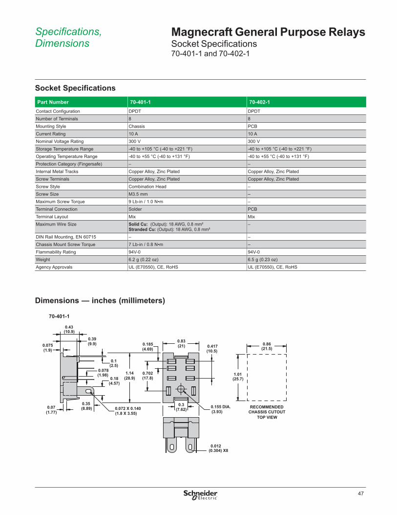
47
Magnecraft General Purpose RelaysSocket Specifications70-401-1 and 70-402-1
Socket SpecificationsPart Number 70-401-1 70-402-1
Contact Configuration DPDT DPDTNumber of Terminals 8 8Mounting Style Chassis PCBCurrent Rating 10 A 10 ANominal Voltage Rating 300 V 300 VStorage Temperature Range -40 to +105 °C (-40 to +221 °F) -40 to +105 °C (-40 to +221 °F)Operating Temperature Range -40 to +55 °C (-40 to +131 °F) -40 to +55 °C (-40 to +131 °F)Protection Category (Fingersafe) – –Internal Metal Tracks Copper Alloy, Zinc Plated Copper Alloy, Zinc PlatedScrew Terminals Copper Alloy, Zinc Plated Copper Alloy, Zinc PlatedScrew Style Combination Head –Screw Size M3 .5 mm –Maximum Screw Torque 9 Lb-in / 1 .0 N•m –Terminal Connection Solder PCBTerminal Layout Mix MixMaximum Wire Size Solid Cu: (Output): 18 AWG, 0 .8 mm²
Stranded Cu: (Output): 18 AWG, 0 .8 mm²–
DIN Rail Mounting, EN 60715 – –Chassis Mount Screw Torque 7 Lb-in / 0 .8 N•m –Flammability Rating 94V-0 94V-0Weight 6 .2 g (0 .22 oz) 6 .5 g (0 .23 oz)Agency Approvals UL (E70550), CE, RoHS UL (E70550), CE, RoHS
Dimensions — inches (millimeters)
70-401-1
(17.8)0.7021.14
(28.9)
(4.69)0.185
(7.62)0.3
0.012(0.304) X8
0.155 DIA.(3.93)(1.77)
0.07
(1.98)0.078
(8.89)0.35
(21)0.83
(1.9)0.075
(10.9)0.43
0.39(9.9)
0.1
(1.8 X 3.55)0.072 X 0.140
0.18(4.57)
(2.5)
(10.5)0.417
RECOMMENDEDCHASSIS CUTOUT
(25.7)1.01
TOP VIEW
(21.5)0.86
Specifications, Dimensions

48
Magnecraft General Purpose RelaysSocket Specifications70-401-1 and 70-402-1
Wiring Diagrams
Dimensions — inches (millimeters)
70-402-1
0.086(2.18) DIA.8 PLACES
0.075(1.9)
(15.74)0.62
(10.0)0.394
0.18(4.57)
(11.1)0.44
0.39(9.9)
(1.98)0.078
1.14(29.1)
(0.91)
(1.98)0.078
0.036
(6.17)0.243
0.155 DIA.
(0.381)0.015
(21.1)0.833
(7.62)0.3
(3.93)
(4.699)
(10.59)
0.672(17.06)
0.417
0.185
RECOMMENDEDCIRCUIT BOARD LAYOUT
TOP VIEW
70-401-1
N.C.
N.O.
COM
INPUT
9
13
5
12
14
8
1 412 42
14 44
11 41
A1A2
IECNEMA
70-402-1
N.C.
N.O.
COM
INPUT
9
13
5
12
14
8
1 412 42
14 44
11 41
A1A2
IECNEMA
Dimensions, Wiring Diagrams
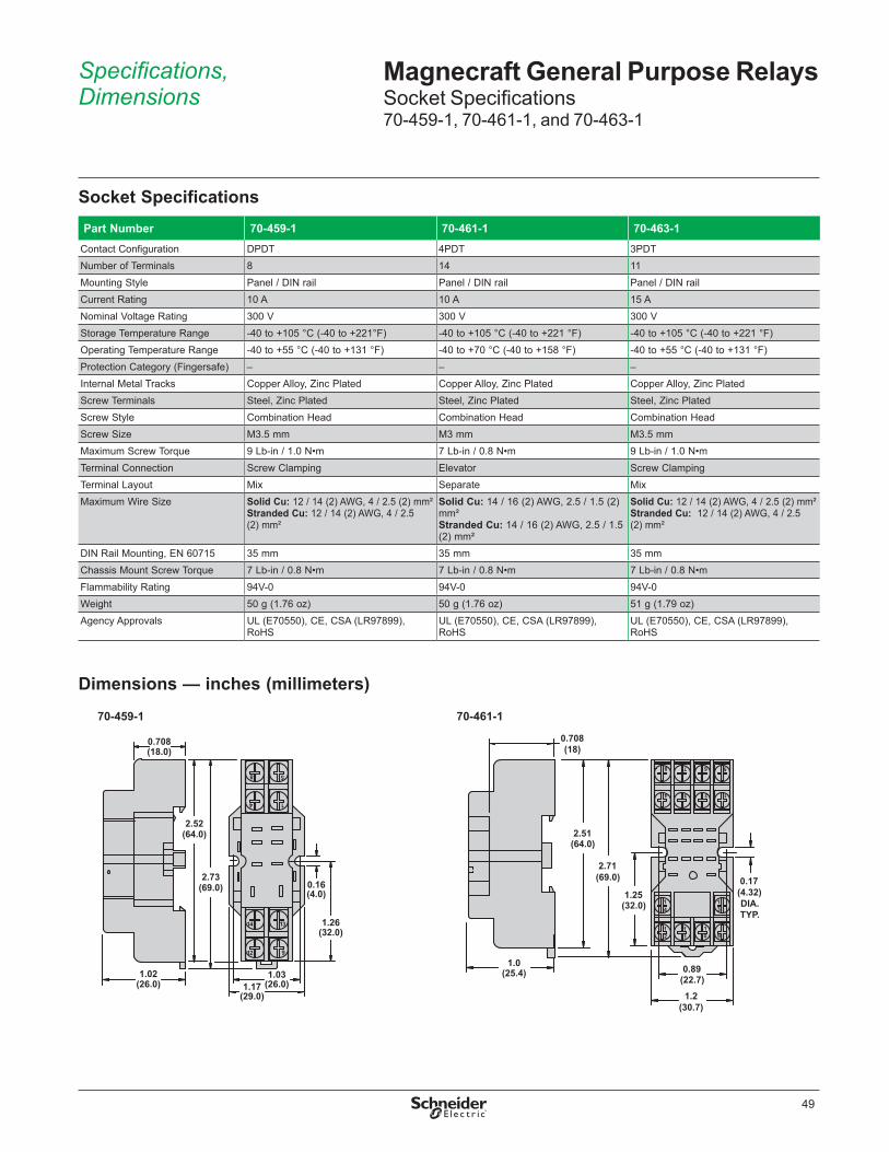
49
Magnecraft General Purpose RelaysSocket Specifications70-459-1, 70-461-1, and 70-463-1
Socket SpecificationsPart Number 70-459-1 70-461-1 70-463-1
Contact Configuration DPDT 4PDT 3PDTNumber of Terminals 8 14 11Mounting Style Panel / DIN rail Panel / DIN rail Panel / DIN railCurrent Rating 10 A 10 A 15 ANominal Voltage Rating 300 V 300 V 300 VStorage Temperature Range -40 to +105 °C (-40 to +221°F) -40 to +105 °C (-40 to +221 °F) -40 to +105 °C (-40 to +221 °F)Operating Temperature Range -40 to +55 °C (-40 to +131 °F) -40 to +70 °C (-40 to +158 °F) -40 to +55 °C (-40 to +131 °F)Protection Category (Fingersafe) – – –Internal Metal Tracks Copper Alloy, Zinc Plated Copper Alloy, Zinc Plated Copper Alloy, Zinc PlatedScrew Terminals Steel, Zinc Plated Steel, Zinc Plated Steel, Zinc PlatedScrew Style Combination Head Combination Head Combination HeadScrew Size M3 .5 mm M3 mm M3 .5 mmMaximum Screw Torque 9 Lb-in / 1 .0 N•m 7 Lb-in / 0 .8 N•m 9 Lb-in / 1 .0 N•mTerminal Connection Screw Clamping Elevator Screw ClampingTerminal Layout Mix Separate MixMaximum Wire Size Solid Cu: 12 / 14 (2) AWG, 4 / 2 .5 (2) mm²
Stranded Cu: 12 / 14 (2) AWG, 4 / 2 .5 (2) mm²
Solid Cu: 14 / 16 (2) AWG, 2 .5 / 1 .5 (2) mm²Stranded Cu: 14 / 16 (2) AWG, 2 .5 / 1 .5 (2) mm²
Solid Cu: 12 / 14 (2) AWG, 4 / 2 .5 (2) mm²Stranded Cu: 12 / 14 (2) AWG, 4 / 2 .5 (2) mm²
DIN Rail Mounting, EN 60715 35 mm 35 mm 35 mmChassis Mount Screw Torque 7 Lb-in / 0 .8 N•m 7 Lb-in / 0 .8 N•m 7 Lb-in / 0 .8 N•mFlammability Rating 94V-0 94V-0 94V-0Weight 50 g (1 .76 oz) 50 g (1 .76 oz) 51 g (1 .79 oz)Agency Approvals UL (E70550), CE, CSA (LR97899),
RoHSUL (E70550), CE, CSA (LR97899), RoHS
UL (E70550), CE, CSA (LR97899), RoHS
Dimensions — inches (millimeters)
70-459-1
8 5
(26.0)1.02
(29.0)1.17
4
14
12
(26.0)1.03
0.16(4.0)
1
(32.0)13 1.26
9
(69.0)
(64.0)
2.73
2.52
0.708(18.0)
70-461-1
2.71(69.0)
(64.0)2.51
(25.4)1.0
9
5
14
8
3
7 6
2
11
41
21
31
01
(22.7)0.89
0.17(4.32)DIA.TYP.
(30.7)1.2
1.25(32.0)
0.708(18)
Specifications, Dimensions

50
Magnecraft General Purpose RelaysSocket Specifications70-459-1, 70-461-1, and 70-463-1
Dimensions — inches (millimeters)
Wiring Diagrams
70-463-1
(80.0)3.14
0.15(3.81)
9 8
B
(76.0)3.0
3 2
7
A
1
1.69
(39.0)1.53
6 5
(35.0)1.37
(43.0)
4
(26.0)1.03
(38.0)1.5
0.4(10.0)
70-459-1
8
4
14
5
1
13
12 9
44
42
14
12
41 11
A2 A1
N.C.N.O.
COM
INPUT
8 54 1
14 13
12 9
IECNEMA
INPUT
70-461-1
8
4
7 56
3 12
101112
14 13
941 31 21 11
A2 A1
42 32 22 12
44 34 24 14
N.C.N.O.
COM
INPUT
8 7 6 54 3 2 1
14 13
9101112
IECNEMA
INPUT
70-463-1
B A
79 8
2 13
456
21 31 11
22 32 12
24 34 14
A2 A1
63 2
5 41
B
9 8 7
A INPUT
COM
N.C.
N.O.
IECNEMA
INPUT
Dimensions, Wiring Diagrams

51
Magnecraft General Purpose RelaysSocket Specifications70-464-1 and 70-465-1
Socket SpecificationsPart Number 70-464-1 70-465-1
Contact Configuration DPDT 3PDTNumber of Terminals 8 11Mounting Style Panel / DIN rail Panel / DIN railCurrent Rating 15 / 10 A 15 / 5 ANominal Voltage Rating 300 / 600 V 300 / 600 VStorage Temperature Range -40 to +105 °C (-40 to +221 °F) -40 to +105 °C (-40 to +221 °F)Operating Temperature Range -40 to +55 °C (-40 to +131 °F) -40 to +55 °C (-40 to +131 °F)Protection Category (Fingersafe) – –Internal Metal Tracks Copper Alloy, Zinc Plated Copper Alloy, Zinc PlatedScrew Terminals Steel, Zinc Plated Steel, Zinc PlatedScrew Style Combination Head Combination HeadScrew Size M3 .5 mm M3 .5 mmMaximum Screw Torque 9 Lb-in / 1 .0 N•m 9 Lb-in / 1 .0 N•mTerminal Connection Screw Clamping Screw ClampingTerminal Layout Mix MixMaximum Wire Size Solid Cu: 12/14 (2) AWG, 4/2 .5 (2) mm²
Stranded Cu: 12/14 (2) AWG, 4/2 .5 (2) mm²Solid Cu: 12/14 (2) AWG, 4/2 .5 (2) mm² Stranded Cu: 12/14 (2) AWG, 4/2 .5 (2) mm²
DIN Rail Mounting, EN 60715 35 mm 35 mmChassis Mount Screw Torque 7 Lb-in / 0 .8 N•m 7 Lb-in / 0 .8 N•mFlammability Rating 94V-0 94V-0Weight 40 g (1 .41 oz) 57 g (2 .01 oz)Agency Approvals UL (E70550), CE, CSA (LR97899), RoHS UL (E70550), CE, CSA (LR97899), RoHS
Dimensions — inches (millimeters)
Wiring Diagrams
70-464-1
3 54 6
82 1
(4.2)0.16
7
(33)1.29 (40)
1.6
(54)2.12
2.02(51)
(24.6)0.97
(25.6)1.01
0.59(15)
70-465-1
34
56
7
112
110
89
(59.0)(52.0)2.06
2.32
(54.8)2.16
2.05(52.0)
(24.6)0.97
(40.0)1.6 DIA.
1.02(25.0)
70-464-1
3 4
2 1
65
8 7
14 12 22 24
A1 11 21 A2
3
4
2
1
6
5
8
7
INPUT INPUT
IECNEMA
70-465-1
54
5 76
32 10
1 11
8
914
A1 A211 31
34
12
22 2421
32
111
3 9
102
4 8
67
INPUT INPUT
IECNEMA
Specifications, Dimensions, Wiring Diagrams

52
Magnecraft General Purpose RelaysSocket Specifications70-750DL8-1 and 70-750DL11-1
Socket SpecificationsPart Number 70-750DL8-1 70-750DL11-1
Contact Configuration DPDT 3PDTNumber of Terminals 8 11Mounting Style Panel / DIN rail Panel / DIN railCurrent Rating 16 A 16 ANominal Voltage Rating 300 V 600 VStorage Temperature Range -40 to +105 °C (-40 to +221 °F) -40 to +105 °C (-40 to +221 °F)Operating Temperature Range -40 to +55 °C (-40 to +131 °F) -40 to +55 °C (-40 to +131 °F)Protection Category (Fingersafe) IP 20 IP 20Internal Metal Tracks Copper Alloy, Zinc Plated Copper Alloy, Zinc PlatedScrew Terminals Steel, Zinc Plated Steel, Zinc PlatedScrew Style Combination Head Combination HeadScrew Size M3 .5 mm M3 .5 mmMaximum Screw Torque 9 Lb-in / 1 .0 N•m 9 Lb-in / 1 .0 N•mTerminal Connection Screw Clamping Screw ClampingTerminal Layout Mix MixMaximum Wire Size Solid Cu: 12/14 (2) AWG, 4/2 .5 (2) mm²
Stranded Cu: 12/14 (2) AWG, 4/2 .5 (2) mm²Solid Cu: 12/14 (2) AWG, 4/2 .5 (2) mm²Stranded Cu: 12/14 (2) AWG, 4/2 .5 (2) mm²
DIN Rail Mounting, EN 60715 35 mm 35 mmChassis Mount Screw Torque 7 Lb-in / 0 .8 N•m 7 Lb-in / 0 .8 N•mFlammability Rating 94V-0 94V-0Weight 60 g (2 .12 oz) 78 g (2 .75 oz)Agency Approvals UL (E70550), CE, CSA (LR40787), RoHS UL (E70550), CE, CSA (LR40787), RoHS
Dimensions — inches (millimeters)70-750DL11-1
(38.0)1.5
(3.8)0.15
(76.8)3.02
(37.0)1.45
(81.0)3.19
(40.0)1.58
(34.2)1.35
11
4
1
12
14
3
A2
10
5
22
21
24
6
7
A1
2INPUTINPUT
34
9
3111
32
8
1.1(27.9)
NEMA:IEC:
70-750DL8-1
(36.0)1.42
(3.8)0.15
1.1(27.9)
11
4112
14
3
A2
7
5
22
2124
6 8
A1
2
(72.7)2.86
(36.0)1.42
INPUTINPUT
(77.5)3.0
(40.0)1.58
(30.0)1.2
NEMA:IEC:
Specifications, Dimensions

53
Magnecraft General Purpose RelaysSocket Specifications70-750DL8-1, 70-750DL11-1, 70-750E8, and 70-750E11-1
70-750DL11-1
5
34 149 3
3111 6
21578
32 2224
111
412
11 1
39
10 2
48
67
A1A210
Coil BusJumper 2
MODULEINPUT
INPUT
IECNEMA
70-750DL8-1
27Coil BusJumper
A1A2
5 4
7
8 1
2
6 3
21 14246 38
11 12225 1 4
MODULEINPUT
INPUT
IECNEMA
Wiring Diagrams
Socket SpecificationsPart Number 70-750E8-1 70-750E11-1
Contact Configuration DPDT 3PDTNumber of Terminals 8 11Mounting Style Panel / DIN rail Panel / DIN railCurrent Rating 12 A 12 ANominal Voltage Rating 300 V 300 VStorage Temperature Range -40 to +105 °C (-40 to +221 °F) -40 to +105 °C (-40 to +221 °F)Operating Temperature Range -40 to +55 °C (-40 to +131 °F) -40 to +55 °C (-40 to +131 °F)Protection Category (Fingersafe) IP 20 IP 20Internal Metal Tracks Copper Alloy, Zinc Plated Copper Alloy, Zinc PlatedScrew Terminals Steel, Zinc Plated Steel, Zinc PlatedScrew Style Combination Head Combination HeadScrew Size M3 .5 mm M3 .5 mmMaximum Screw Torque 9 Lb-in / 1 .0 N•m 9 Lb-in / 1 .0 N•mTerminal Connection Elevator ElevatorTerminal Layout Separate SeparateMaximum Wire Size Solid Cu: 12/14 (2) AWG, 4/2 .5 (2) mm²
Stranded Cu: 12/14 (2) AWG, 4/2 .5 (2) mm²Solid Cu: 12/14 (2) AWG, 4/2 .5 (2) mm²Stranded Cu: 12/14 (2) AWG, 4/2 .5 (2) mm²
DIN Rail Mounting, EN 60715 35 mm 35 mmChassis Mount Screw Torque 7 Lb-in / 0 .8 N•m 7 Lb-in / 0 .8 N•mFlammability Rating 94V-0 94V-0Weight 85 g (3 .0 oz) 85 g (3 .0 oz)Agency Approvals UL (E70550), CE, CSA (LR40787), RoHS UL (E70550), CE, CSA (LR40787), RoHS
Wiring Diagrams, Specifications

54
Magnecraft General Purpose RelaysSocket Specifications70-750E8 and 70-750E11-1
Dimensions — inches (millimeters)
70-750E11-1
INPUT A1
10
INPUT A2
2A1A2 A2 31 21 11
10 1110 6 1 2
1434 2432 22 12
9 78 435
2.95
(22.0)0.86
(27.0)1.06
1.45
1.49
0.12
(75.0)
(37.0)
(30.0)
(38.0)
NEMA:IEC:
(3.1)0.12
70-750E8-1
11
7
7
INPUT A1INPUT A2
A2
7
A2
8
21
21
A1
12
56
24
4
22
3
14
2
(3.1)2.95
1.45
0.121.49
0.12
0.86(22.0)
(27.0)1.06
(75.0)
(30.0)
(38.0)
(37.0)NEMA:IEC:
Wiring Diagrams
70-750E11-1
10 111 6 211A2 31 21 A1
1434 24 22 1239 7 5 4
10
832
A2
4
39
8
7 56
110
112
INPUTINPUT
MODULEINPUT
IECNEMA
Dimensions, Wiring Diagrams
70-750E8-1
7 18 211A2 21 A1
1224 22 1446 5 3
7A2
4
3
8
7
5
6
1
2
INPUTINPUT
MODULEINPUT
IECNEMA

55
Magnecraft General Purpose RelaysSocket Specifications70-750EL8-1 and 70-750EL11-1
Socket SpecificationsPart Number 70-750EL8-1 70-750EL11-1
Contact Configuration DPDT 3PDTNumber of Terminals 8 11Mounting Style Panel / DIN rail Panel / DIN railCurrent Rating 16 A 16 ANominal Voltage Rating 300 V 300 VStorage Temperature Range -40 to +105 °C (-40 to +221 °F) -40 to +105 °C (-40 to +221 °F)Operating Temperature Range -40 to +55 °C (-40 to +131 °F) -40 to +55 °C (-40 to +131 °F)Protection Category (Fingersafe) IP 20 IP20Internal Metal Tracks Copper Alloy, Zinc Plated Copper Alloy, Zinc PlatedScrew Terminals Steel, Zinc Plated Steel, Zinc PlatedScrew Style Combination Head Combination HeadScrew Size M3 .5 mm M3 .5 mmMaximum Screw Torque 9 Lb-in / 1 .0 N•m 9 Lb-in / 1 .0 N•mTerminal Connection Elevator ElevatorTerminal Layout Separate SeparateMaximum Wire Size Solid Cu: 12/14 (2) AWG, 4/2 .5 (2) mm²
Stranded Cu: 12/14 (2) AWG, 4/2 .5 (2) mm²Solid Cu: 12 / 14 (2) AWG, 4 / 2 .5 (2) mm² Stranded Cu: 12 / 14 (2) AWG, 4 / 2 .5 (2) mm²
DIN Rail Mounting, EN 60715 35 mm 35 mmChassis Mount Screw Torque 7 Lb-in / 0 .8 N•m 7 Lb-in / 0 .8 N•mFlammability Rating 94V-0 94V-0Weight 79 g (2 .79 oz) 79 g (2 .79 oz)Agency Approvals UL (E70550), CE, CSA (LR40787), RoHS UL (E70550), CE, CSA (LR40787), RoHS
Dimensions — inches (millimeters)
70-750EL11-1
A2 A17 2
INPUT
124
111
31
32
11
2478
216
143
349
225
(36.0)
(40.0)
(92.0)
(96.0)
(30.0)
(7.0)
(63.0)
3.62
3.77
2.481.4
1.18
1.60
0.27
0.74(19.0)
NEMA:IEC:
70-750EL8-1
A2 A1
INPUT7 2
14
3
124
22
24
5
21
86
111
(36.0)
(40.0)
(92.0)
(96.0)
(30.0)
(7.0)
(45.0)
3.62
3.77
1.77 1.4
1.18
1.60
0.27
0.74(19.0)
NEMA:IEC:
Specifications, Dimensions
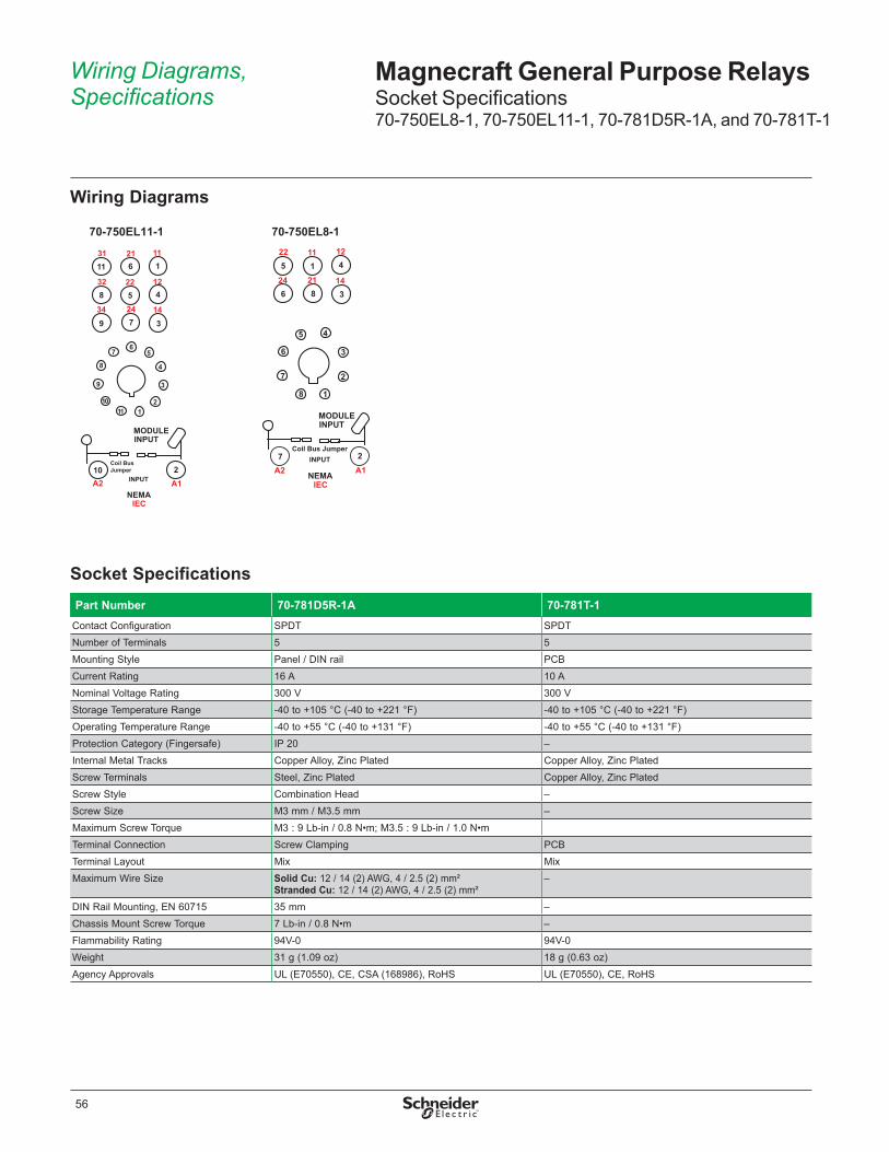
56
Magnecraft General Purpose RelaysSocket Specifications70-750EL8-1, 70-750EL11-1, 70-781D5R-1A, and 70-781T-1
Wiring Diagrams
70-750EL11-1
32
24
2131
34
22 12
11
14
A2 A110
7
5
39
8 4
11 6 1
2
1
6
11
8
9
7
3
4
10 2
5
Coil BusJumper
MODULEINPUT
INPUT
IECNEMA
70-750EL8-1
A2
22
24
12
14
11
21
Coil Bus Jumper
A1
8
7
6
5 4
3
2
1
MODULEINPUT
7 2
18
45
36
INPUT
IECNEMA
Socket SpecificationsPart Number 70-781D5R-1A 70-781T-1
Contact Configuration SPDT SPDTNumber of Terminals 5 5Mounting Style Panel / DIN rail PCBCurrent Rating 16 A 10 ANominal Voltage Rating 300 V 300 VStorage Temperature Range -40 to +105 °C (-40 to +221 °F) -40 to +105 °C (-40 to +221 °F)Operating Temperature Range -40 to +55 °C (-40 to +131 °F) -40 to +55 °C (-40 to +131 °F)Protection Category (Fingersafe) IP 20 –Internal Metal Tracks Copper Alloy, Zinc Plated Copper Alloy, Zinc PlatedScrew Terminals Steel, Zinc Plated Copper Alloy, Zinc PlatedScrew Style Combination Head –Screw Size M3 mm / M3 .5 mm –Maximum Screw Torque M3 : 9 Lb-in / 0 .8 N•m; M3 .5 : 9 Lb-in / 1 .0 N•mTerminal Connection Screw Clamping PCBTerminal Layout Mix MixMaximum Wire Size Solid Cu: 12 / 14 (2) AWG, 4 / 2 .5 (2) mm²
Stranded Cu: 12 / 14 (2) AWG, 4 / 2 .5 (2) mm²–
DIN Rail Mounting, EN 60715 35 mm –Chassis Mount Screw Torque 7 Lb-in / 0 .8 N•m –Flammability Rating 94V-0 94V-0Weight 31 g (1 .09 oz) 18 g (0 .63 oz)Agency Approvals UL (E70550), CE, CSA (168986), RoHS UL (E70550), CE, RoHS
Wiring Diagrams, Specifications
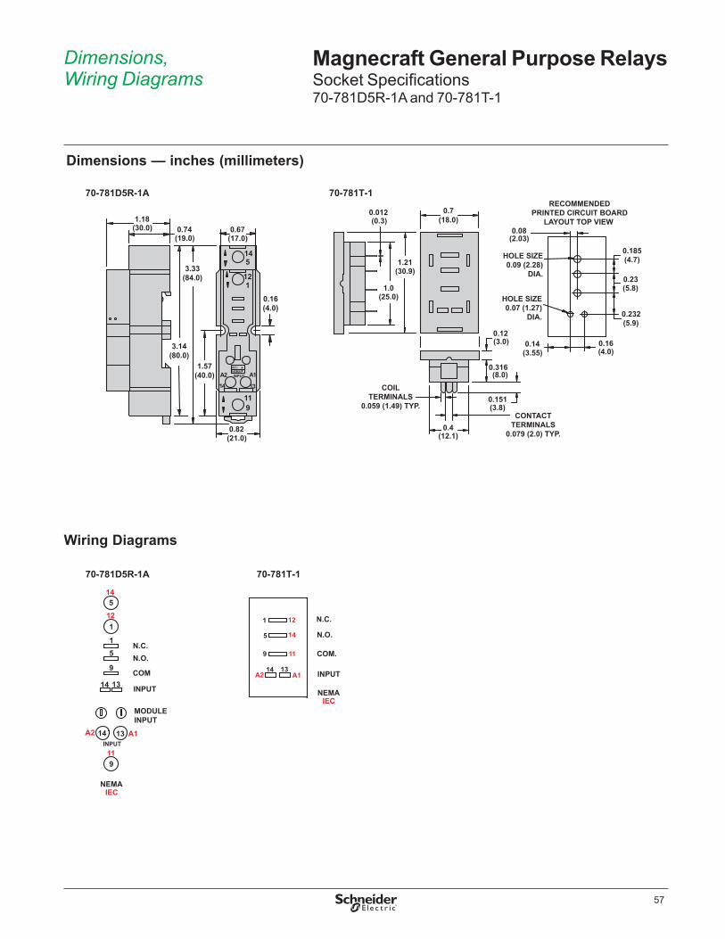
57
Magnecraft General Purpose RelaysSocket Specifications70-781D5R-1A and 70-781T-1
Dimensions — inches (millimeters)
70-781D5R-1A
9
14 13
1
5
A2 A1
11
12
14
INPUT
(21.0)0.82
3.14(80.0)
0.67(17.0)
3.33(84.0)
(30.0)1.18
1.57(40.0)
0.16(4.0)
0.74(19.0)
NEMA:IEC:
70-781T-1
0.12(3.0)
0.151(3.8)
(8.0)
0.4(12.1)
CONTACTTERMINALS
0.079 (2.0) TYP.
COILTERMINALS
0.059 (1.49) TYP.
0.316
RECOMMENDEDPRINTED CIRCUIT BOARD
LAYOUT TOP VIEW
0.232(5.9)
0.16(4.0)
0.185(4.7)
0.23(5.8)
0.08(2.03)
HOLE SIZE0.07 (1.27)
DIA.
HOLE SIZE0.09 (2.28)
DIA.
0.012
1.0(25.0)
(0.3)
(30.9)1.21
(18.0)0.7
(3.55)0.14
Wiring Diagrams
70-781D5R-1A
119
14
INPUT
A2 14 A113
1125
COM
N.C.N.O.
14 13
MODULEINPUT
15
INPUT
9
IECNEMA
70-781T-1
IECNEMA
119
A214 13
A1
5 14
1 12
INPUT
N.O.
COM.
N.C.
Dimensions, Wiring Diagrams

58
Magnecraft General Purpose RelaysSocket Specifications70-782D8-1A and 70-782D14-1
Socket SpecificationsPart Number 70-782D8-1A 70-782D14-1
Contact Configuration DPDT 4PDTNumber of Terminals 8 14Mounting Style Panel / DIN rail Panel / DIN railCurrent Rating 16 A 10 ANominal Voltage Rating 300 V 300 VStorage Temperature Range -40 to +105 °C (-40 to +221 °F) -40 to +105 °C (-40 to +221 °F)Operating Temperature Range -40 to +55 °C (-40 to +131 °F) -40 to +70 °C (-40 to +158 °F)Protection Category (Fingersafe) IP 20 IP 20Internal Metal Tracks Copper Alloy, Zinc Plated Copper Alloy, Zinc PlatedScrew Terminals Steel, Zinc Plated Steel, Zinc PlatedScrew Style Combination Head Combination HeadScrew Size M3 .5 mm M3 mmMaximum Screw Torque 9 Lb-in / 1 .0 N•m 7 Lb-in / 0 .8 N•mTerminal Connection Screw Clamping Screw ClampingTerminal Layout Mix MixMaximum Wire Size Solid Cu: 12 / 14 (2) AWG, 4 / 2 .5 (2) mm²
Stranded Cu: 12 / 14 (2) AWG, 4 / 2 .5 (2) mm²Solid Cu: 12 / 14 (2) AWG, 4 / 2 .5 (2) mm² Stranded Cu: 12 / 14 (2) AWG, 4 / 2 .5 (2) mm²
DIN Rail Mounting, EN 60715 35 mm 35 mmChassis Mount Screw Torque 7 Lb-in / 0 .8 N•m 7 Lb-in / 0 .8 N•mFlammability Rating 94V-0 94V-0Weight 55 g (1 .94 oz) 62 g (2 .19 oz)Agency Approvals UL (E70550), CE, CSA (LR40787), RoHS UL (E70550), CE, CSA (LR40787), RoHS
Dimensions — inches (millimeters)
70-782D14-1
(3.8)
(30.0)
(21.0)
(84.0)
(79.0)
(6.4)
(39.5)
(61.0)
(40.0)
(3.8)(25.5)0.14
1.0
1.55
0.250.82
0.143.3
3.11
1.57
2.4
1.18
44 14
1112 10
INPUTINPUT
31
14
A2
41
139
A1
21
11
34 2 1
8
3242
5
22 12
347
246
0.74(19.0)
70-782D8-1A
1.18(30.0)
0.24(6.0)
2.67(68.0)
3.14(80.0)
1.18(30.0)
3.33(84.0)
1.57(40.0)
1.06(26.0)
12 9
14 13
4 1
8 5
41 11
A2 A1
42 12
1444
INPUT INPUT
0.16(4.0)
0.74(19.0)
NEMA:IEC:
Specifications, Dimensions

59
Magnecraft General Purpose RelaysSocket Specifications70-782D8-1A, 70-782D14-1, 70-782E14-1, and 70-782EL8-1
Wiring Diagrams
70-782D14-1
A214
1241
9
A113
11 1031 21
11
442
123
2434
1467
44
12223258
INPUT
COM
N.O.N.C.4 3 2 1
58 67
12 11 10
14 13
9
MODULEINPUT
IECNEMA
INPUT
70-782D8-1A
COM
N.O.N.C.
INPUT
INPUT
119
4112
13A1
14A2
12424 1
8 51444
8 54 1
14 13
12 9
MODULEINPUT
IECNEMA
Socket SpecificationsPart Number 70-782E14-1 70-782EL8-1
Contact Configuration 4PDT DPDTNumber of Terminals 14 8Mounting Style Panel / DIN rail Panel / DIN railCurrent Rating 10 A 12 ANominal Voltage Rating 300 V 300 VStorage Temperature Range -40 to +105 °C (-40 to +221 °F) -40 to +105 °C (-40 to +221 °F)Operating Temperature Range -40 to +70 °C (-40 to +158 °F) -40 to +55 °C (-40 to +131 °F)Protection Category (Fingersafe) IP 20 IP 20Internal Metal Tracks Copper Alloy, Zinc Plated Copper Alloy, Zinc PlatedScrew Terminals Steel, Zinc Plated Steel, Zinc PlatedScrew Style Combination Head Combination HeadScrew Size M3 mm M3 .5 mmMaximum Screw Torque 7 Lb-in / 0 .8 N•m 9 Lb-in / 1 .0 N•mTerminal Connection Elevator ElevatorTerminal Layout Separate SeparateMaximum Wire Size Solid Cu: 14 / 16 (2) AWG, 2 .5 / 1 .5 (2) mm²
Stranded Cu: 14 / 16 (2) AWG, 2 .5 / 1 .5 (2) mm²Solid Cu: 12 / 14 (2) AWG, 4 / 2 .5 (2) mm²Stranded Cu: 12 / 14 (2) AWG, 4 / 2 .5 (2) mm²
DIN Rail Mounting, EN 60715 35 mm 35 mmChassis Mount Screw Torque 7 Lb-in / 0 .8 N•m 7 Lb-in / 0 .8 N•mFlammability Rating 94V-0 94V-0Weight 56 g (1 .98 oz) 46 g (1 .62 oz)Agency Approvals UL (E70550) CE, CSA (LR40787), RoHS UL (E70550), CE, CSA (LR40787), RoHS
Wiring Diagrams, Specifications

60
Dimensions — inches (millimeters)
Magnecraft General Purpose RelaysSocket Specifications70-782E14-1 and 70-782EL8-1
70-782E14-1
1012 11 9
2141 31 11
INPUT14 13
A1A2
68 7 5
2444 34 14
12
1
42
3
22
24
32
(26.9)
(22.0)(43.0)
(79.0)
(17.0)
(3.0)
(40.0)
1.69
3.12
0.67
1.57
0.12
0.86
1.06
NEMA:IEC:
70-782E14-1
N.O.
INPUT
COM
N.C.
112
222
332
442
514
624
734
844
A113
A214
119
2110
3111
4112
1314
8 7 6 534 2 1
12 11 10 9
IECNEMA
MODULEINPUT
INPUT
1.06(26.9)
A1
INPUT
A2
14 13
12
5
911
14
4 1
8
12
42
41
44
NEMA:IEC:
70-782EL8-1
0.9(22.0)(19.0)
(61.0)2.4
0.74
3.11(79.0)
(85.0)3.34
(38.0)1.49
0.2(5.6)
70-782EL8-1
1
A1
125
911
14
INPUTA214
4
8
12
42
41
44
13
N.O.
INPUT
COM
N.C.4 1
58912
14 13
MODULEINPUT
IECNEMA
Wiring Diagrams
Dimensions, Wiring Diagrams

61
Magnecraft General Purpose RelaysSocket Specifications70-782EL14-1
Socket SpecificationsPart Number 70-782EL14-1
Contact Configuration 4PDTNumber of Terminals 14Mounting Style Panel / DIN railCurrent Rating 10 ANominal Voltage Rating 300 VStorage Temperature Range -40 to +105 °C (-40 to +221 °F)Operating Temperature Range -40 to +70 °C (-40 to +158 °F)Protection Category (Fingersafe) IP 20Internal Metal Tracks Copper Alloy, Zinc PlatedScrew Terminals Steel, Zinc PlatedScrew Style Combination HeadScrew Size M3 mmMaximum Screw Torque 7 Lb-in / 0 .8 N•mTerminal Connection ElevatorTerminal Layout SeparateMaximum Wire Size Solid Cu: 14 / 16 (2) AWG, 2 .5 / 1 .5 (2) mm²
Stranded Cu: 14 / 16 (2) AWG, 2 .5 / 1 .5 (2) mm²DIN Rail Mounting, EN 60715 35 mmChassis Mount Screw Torque 7 Lb-in / 0 .8 N•mFlammability Rating 94V-0Weight 62 g (2 .19 oz)Agency Approvals UL (E70550), CE, CSA (LR40787), RoHS
Dimensions — inches (millimeters)
70-782EL14-1
0.9(22)1.06
(25.4)(19.0)(61.0)
2.40.74
3.11(79.0)
(85.0)3.34
(38.0)1.49
0.2(5.6)
1
A1
12
5
9
11
14
INPUT
A2
14
34
78
1112
3242
41 31
3444
13
2
6
10
22
21
24
NEMA:IEC:
Specifications, Dimensions, Wiring Diagram
Wiring Diagram
70-782EL14-1
A214 13INPUT
A1
44
41
424
8
12
2323
22 121
146
347
245
2110
3111
119
12345678
9101112
14 13
MODULEINPUT
COM
INPUT
N.O.N.C.
IECNEMA

62
Magnecraft General Purpose RelaysSocket Specifications70-783D11-1A and 70-784D14-1
Socket SpecificationsPart Number 70-783D11-1A 70-784D14-1
Contact Configuration 3PDT 4PDTNumber of Terminals 11 14Mounting Style Panel / DIN rail Panel / DIN railCurrent Rating 16 A 16 A Nominal Voltage Rating 300 V 300 VStorage Temperature Range -40 to +105 °C (-40 to +221 °F) -40 to +105 °C (-40 to +221 °F)Operating Temperature Range -40 to +55 °C (-40 to +131 °F) -40 to +55 °C (-40 to +131 °F)Protection Category (Fingersafe) IP 20 IP 20Internal Metal Tracks Copper Alloy, Zinc Plated Copper Alloy, Zinc PlatedScrew Terminals Steel, Zinc Plated Steel, Zinc PlatedScrew Style Combination Head Combination HeadScrew Size M3 .5 mm M3 .5 mmMaximum Screw Torque 9 Lb-in / 1 .0 N•m 9 Lb-in / 1 .0 N•mTerminal Connection Screw Clamping Screw ClampingTerminal Layout Mix MixMaximum Wire Size Solid Cu: 12 / 14 (2) AWG, 4 / 2 .5 (2) mm²
Stranded Cu: 12 / 14 (2) AWG, 4 / 2 .5 (2) mm²Solid Cu: 12 / 14 (2) AWG, 4 / 2 .5 (2) mm²Stranded Cu: 12 / 14 (2) AWG, 4 / 2 .5 (2) mm²
DIN Rail Mounting, EN 60715 35 mm 35 mmChassis Mount Screw Torque 7 Lb-in / 0 .8 N•m 7 Lb-in / 0 .8 N•mFlammability Rating 94V-0 94V-0Weight 55 g (1 .94oz) 62 g (2 .19 oz)Agency Approvals CE, RoHS, UL,(E70550) CSA (LR40787) CE, RoHS, UL,(E70550) CSA (LR40787)
Specifications

63
Wiring Diagrams
Magnecraft General Purpose RelaysSocket Specifications70-783D11-1A and 70-784D14-1
Dimensions — inches (millimeters)
70-783D11-1A
0.16(4.0)
0.24(6.0)
2.67(68.0)
3.14(80.0)
1.18(30.0)
3.33(84.0)
1.57(40.0)
21 1141
12 10 9
INPUT
14
A2
13
A1INPUT
8
4
42 22
6 5
2 1
44 24
12
14
1.57(40.0)
(37.0)1.45
(28.0)1.100.74
(19.0)
NEMA:IEC:
70-783D11-1A
N.C.N.O.
COM
INPUT
13A214
214110 912
A1
11
44
4428
2
614
1125
24
22
4 2 18 6 5
12 10 9
14 13
MODULEINPUT
IECNEMA
INPUT
70-784D14-1
0.16 (4.0)
1.96(50.0)
0.24(6.0)
2.67(68.0)
3.14(80.0)
1.18(30.0)
3.33(84.0)
1.57(40.0) A2
14
1241
INPUT INPUTA113
910
112131
11
67
2434
8
44
234
42 2232
5
14
1
12
1.81(46.0)
1.41(36.0)
0.74(19.0)
NEMA:IEC:
70-784D14-1
INPUT
N.O.N.C.
COM
14
4112
A213
1121910
A1
3111
223242 12
34678
2444
234
145
1
4 3 2 18 7 6 5
12 11 10 9
MODULEINPUT
IECNEMA
INPUT
Dimensions, Wiring Diagrams

64
Magnecraft General Purpose RelaysSocket Specifications70-788EL11-1
Socket SpecificationsPart Number 70-788EL11-1
Contact Configuration 3PDTNumber of Terminals 11Mounting Style DIN railCurrent Rating 25 ANominal Voltage Rating 300 VStorage Temperature Range -40 to +105 °C (-40 to +221 °F)Operating Temperature Range -40 to +55 °C (-40 to +131 °F)Protection Category (Fingersafe) IP 20Internal Metal Tracks Copper Alloy, Zinc PlatedScrew Terminals Steel, Zinc PlatedScrew Style Combination HeadScrew Size M3 .5 mmMaximum Screw Torque 9 Lb-in / 1 .0 N•mTerminal Connection ElevatorTerminal Layout SeparateMaximum Wire Size Solid Cu: 10 / 14 (2) AWG, 6 / 2 .5 (2) mm²
Stranded Cu: 10 / 14 (2) AWG, 6 / 2 .5 (2) mm²DIN Rail Mounting, EN 60715 35 mmChassis Mount Screw Torque 7 Lb-in / 0 .8 N•mFlammability Rating 94V-0Weight 96 g (3 .39 oz)Agency Approvals UL (E70550), CE, CSA (LR40787), RoHS
Wiring DiagramDimensions — inches (millimeters)
70-788EL11-1
A2 A1
7 2INPUT
121
144
117
223
322
21
24
9
3456
318
(36.0)1.4
(63.0)
(92.0)
(96.0)
2.48
3.62
3.7
NEMA:IEC:
70-788EL11-1
12
1
144
117
223
322
21
249
3456
318
A2B
A1
ACoil BusJumper
B A
9 8 7
6 5 4123
INPUTMODULE
INPUT
COM
N.O.
N.C.
IECNEMA
INPUTINPUT
Specifications, Dimensions, Wiring Diagrams

65
Magnecraft General Purpose RelaysMounting Adapter Specifications
16-781CAll DIN Adapters
0.67(17.0)
0.93(23.7)
1.32(33.5)
1.72(43.6)
0.3(7.6)
0.76(19.2)
0.24(6.1)
0.87(22.2)
0.29(7.4)
0.87(22.2)
0.77(19.6)
0.29(7.4)
1.84(46.7) MAX
1.39(35.2)
1.97(50.0) MAX
2.06(52.2) MAX
0.15(3.9)
1.5(38.0)
16-782C 16-783C 16-784C
42.8 (42.8 MAX)
43.2(43.2 MAX)
1.5(38.0)
1.5(38.0)
1.5(38.0)
1.5(38.0)
0.67(17.0)
0.94(24.0)
1.34(34.0)
0.18(4.6)
0.14(3.6)
0.15(3.8)
0.14(3.6)
0.14(3.6)
0.14(3.6)
0.14(3.6)
0.15(3.8)
1.34(44.0)
0.6(15.6)
0.61(15.6)
0.72(18.3)
0.72(18.3)
16-781C1
All Flange Adapters
16-782C1 16-783C1 16-784C1
Mounting Adapter Dimensions — inches (millimeters)
Mounting Adapter SpecificationsPart Number 16-781C 16-782C 16-783C 16-784C 16-781C1 16-782C2 16-783C1 16-784C1
Mounting Style DIN rail / panel PanelMating Relays 781 Series 792 Series
782 Series783 Series 784 Series 781 Series 792 Series
782 Series783 Series 784 Series
Agency Approvals RoHS
Key Features b No need to purchase a socket b DIN or Panel mounting b Plastic construction b Light weight b Low cost
b Low profile b Write-On label b Narrow mounting b Easy termination
Specifications, Dimensions

66
Contents Magnecraft General Purpose RelaysSocket Accessories
b Overview . . . . . . . . . . . . . . . . . . . . . . . . . . . . . . . . . . . . . . . . . . . . . . . . . . . . . . . . 67
b Hold-Down Clips . . . . . . . . . . . . . . . . . . . . . . . . . . . . . . . . . . . . . . . . . . . . . . . . . . 68
b Insulated Coil Bus Jumper System . . . . . . . . . . . . . . . . . . . . . . . . . . . . . . . . . . . . 71
b DIN Rail and DIN Clip . . . . . . . . . . . . . . . . . . . . . . . . . . . . . . . . . . . . . . . . . . . . . . 71
b ID Tags . . . . . . . . . . . . . . . . . . . . . . . . . . . . . . . . . . . . . . . . . . . . . . . . . . . . . . . . . 71
b Panel Mount Adapter . . . . . . . . . . . . . . . . . . . . . . . . . . . . . . . . . . . . . . . . . . . . . . . 72
b Socket Modules . . . . . . . . . . . . . . . . . . . . . . . . . . . . . . . . . . . . . . . . . . . . . . . . . . 72
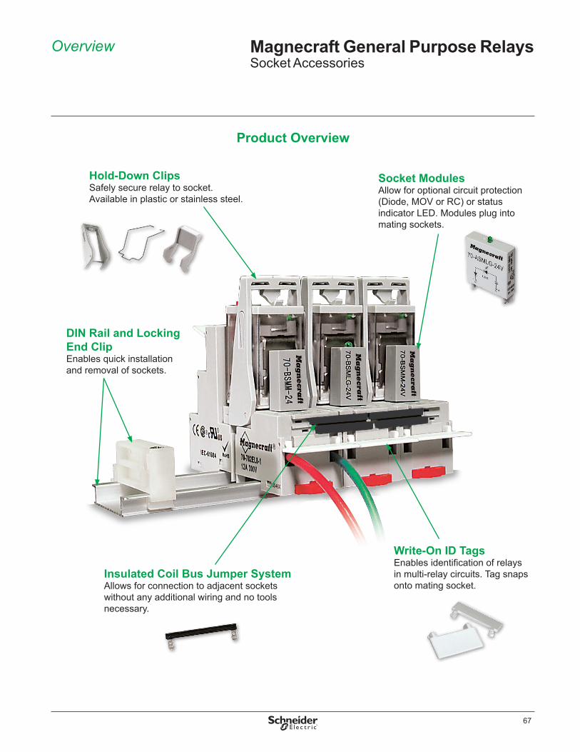
67
Overview Magnecraft General Purpose RelaysSocket Accessories
Hold-Down ClipsSafely secure relay to socket . Available in plastic or stainless steel .
Socket ModulesAllow for optional circuit protection (Diode, MOV or RC) or status indicator LED . Modules plug into mating sockets .
Write-On ID TagsEnables identification of relays in multi-relay circuits . Tag snaps onto mating socket .
Insulated Coil Bus Jumper SystemAllows for connection to adjacent sockets without any additional wiring and no tools necessary .
DIN Rail and Locking End ClipEnables quick installation and removal of sockets .
Product Overview

68
The table below is designed to allow for easy selection of Magnecraft hold-down clips based on socket and relay compatibility .
Key Features b Stainless steel spring clips are designed to secure the relay to the socket in harsh environments b Plastic ejector clips are designed to secure and eject relays from tight, multi-socket applications b Plastic ID clips are designed to allow for easy identification of circuits in multi-relay applications; an ID tag is supplied with each clip
Socket Part Number Relays Clip Part
Number Clip Type
70-124-2 788XBX / 788XCX 16-1351 Spring Clip70-178-1 788XBX / 788XCX 16-1351 Spring Clip70-178-2 788XBX / 788XCX 16-1351 Spring Clip70-378-1 792XDX Control, 782XDXH 16-1342 Spring Clip70-379-1 792XDX Control, 782XDXH 16-1342 Spring Clip70-401-1 782XBX Power 16-1342 Spring Clip70-402-1 782XBX Power 16-1342 Spring Clip70-459-1 782XBX Power 16-1342 Spring Clip70-461-1 792XDX Control, 782XDXH 16-1342 Spring Clip70-463-1 788XBX / 788XCX 16-1351 Spring Clip70-464-1 750XBX, 750XBXH 16-1351 Spring Clip70-465-1 750XCX, 750XCXH 16-1351 Spring Clip70-750DL8-1 750XBX 16-1332 Spring Clip
750XBXH 16-1351 Spring Clip70-750DL11-1 750XCX 16-1332 Spring Clip
750XCXH 16-1351 Spring Clip70-750E8-1 750XBX 16-1344 Spring Clip
750XBX, 750XBXH 16-1351 Spring Clip70-750E11-1 750XCX, 750XCXH 16-1351 Spring Clip70-750EL8-1 750XBX 16-1351 Spring Clip70-750EL11-1 750XCX 16-1351 Spring Clip70-781D5R-1A 781XAX 16-781IDC ID Clip
16-781SC Spring Clip70-781T-1 781XAX 16-781SC Spring Clip70-782D8-1A 782XBX Power 16-1342 Spring Clip
16-782IDC ID Clip782XBX Power (Full-feature cover only) 16-782PC-1 Ejector Clip
70-782D14-1 792XBX / 792XDX Control 16-782SC Spring Clip792XBX / 792XDX Control (Full-feature cover only) 16-782PC-1 Ejector Clip782XDXH 16-1342 Spring Clip
70-782E14-1 792XBX / 792XDX Control 16-782SC Spring Clip792XBX / 792XDX Control (Full-feature cover only) 16-782PC-1 Ejector Clip782XDXH 16-1342 Spring Clip
70-782EL8-1 792XBX Control 16-782SC Spring Clip792XBX Control (Full-feature cover only) 16-782PC-1 Ejector Clip
70-782EL14-1 792XBX / 792XDX Control 16-782SC Spring Clip792XBX / 792XDX Control (Full-feature cover only) 16-782PC-1 Ejector Clip782XDXH 16-1342 Spring Clip
70-783D11-1A 783XCX 16-783IDC ID Clip16-783SC Spring Clip
70-784D14-1 784XDX 16-784IDC ID Clip16-784SC Spring Clip
70-788EL11-1 788XBX / 788XCX 16-1351 Spring Clip
Selection Magnecraft General Purpose RelaysSocket AccessoriesHold-Down Clips

69
Dimensions Magnecraft General Purpose RelaysSocket AccessoriesHold-Down Clips
Hold-Down Clip Dimensions — inches (millimeters)
16-781IDC0.4
(10.16)
0.085(2.15)
0.54(13.71)0.725
(18.41)
1.76(44.7)
0.88(22.35)
0.51(13.0)
0.56(14.2)
1.59(40.5)
0.14(3.5)
16-781SC 16-782IDC0.4
(10.16)
1.84(46.73)
0.935(23.74)
0.08(2.03)
0.85(21.59)
1.01(25.65)
0.966(24.54)
2.211(56.15)
1.063(26.99)
16-782PC0.5
(12.8)0.86
(22.0)0.23(6.0)
1.49(38.0)
16-782SC 16-783IDC0.4
(10.16)
1.86(47.24)
1.0(25.4)
0.08(2.03)
1.27(32.25)1.44
(36.57)
0.5(12.8)
1.22(31.0)
0.28(7.0)
1.5(38.0)
16-783SC 16-784IDC0.4
(10.16)
0.9(22.86)
1.8(45.7)
1.6(40.6)1.76
(44.7)
0.5(12.8)
1.61(41.0)
0.28(7.0)
1.5(38.0)
16-784SC

70
Dimensions Magnecraft General Purpose RelaysSocket AccessoriesHold-Down Clips
Hold-Down Clip Dimensions (continued) — inches (millimeters)
16-13321.55
(39.37)
2.2(55.0)
16-13421.016
(25.81)0.284(7.21)
1.099(27.92)
1.394(35.41)
16-1344
1.32(33.5)
1.665(42.28)
0.182(4.62)
2.8(71.12)
16-13511.377
(34.77) 0.3(7.62)
2.15(54.61)

71
Dimensions Magnecraft General Purpose RelaysSocket AccessoriesInsulated Coil Bus Jumper, DIN Rail and Clip, and ID Tags
(21.5)
(25.0)
(0.64)
(2.6)
(7.4)(2.3)
0.9816-750/788CBJ-1 Coil Bus Jumper
0.10
0.02
0.29
0.840.09
(32)
(35)
(0.64)
(3.2)
(8.3)(2.3)
1.37
16-750/788CBJ-1 Coil Bus Jumper0.12
0.02
0.3
1.250.09
Insulated Coil Bus Jumper Dimensions — inches (millimeters)
ID Tag Dimensions — inches (millimeters)
16-700ST-1 ID Tag/Label
0.12(3.7)
0.19(4.8)
0.46(11.8)
16-750/788FT-1 ID Tag/Label
(12.0) (14.2)
1.2(32.0)
0.47
1.07(27.4)
0.55
16-782FT-1 ID Tag/Label
(11.5) (14.2)
1.06(27.0)
0.45
0.9(23.0)
0.55
0.37(9.4)
1.39(35.5)
1.55(39.5)
1.65(42.0)
1.37(34.7)
1.17(29.7)
0.86(22.0)
16-DCLIP-1 DIN Rail Clip
NOTES:1. THE LIPS AT BASE OF DIN RAIL MAY OR MAY NOT BE PRESENT ON DIN RAIL EXTRUSIONS.
16-700DIN Metal DIN Rail
(5)0.19
1.377+0.011/-0.007(35.0 ± 0.3)
0.99(10.0)0.39
(25.0) (1.0 ± 0.04)0.039
(25.5)1.0
SEENOTE 1
39.3(1000) (7.5 +0.0/-0.4)
0.3
DIN Rail and DIN Clip Dimensions — inches (millimeters)

72
Dimensions Magnecraft General Purpose RelaysSocket AccessoriesPanel Mount Adapter and Socket Modules
Socket Module Dimensions — inches (millimeters)
70-ASM Socket Modules
A1A2
1.60MAX
LED(only on LED modules)
1.37(34.7)
0.384(9.82)
70-BSM Socket Modules
A2 A1
1.05(26.67)MAX.
0.49(12.4) 0.34
(8.63)
Socket Module Wiring Diagrams
70-ASM & 70-BSM Socket Modules
MOVSuppressor
A2 A1
A2
ProtectionDiode +
A1
LEDIndicator
70-ASMM70-BSMM
70-ASMLG70-BSMLG
70-ASMR70-BSMR
70-ASMD70-BSMD
A2+
A1
A2 A1
RCSuppressor
0.165 TYP(4.19)
1.39 MAX(35.3)
0.06 TYP(1.4)
16-788C1 Panel Mount Adapter
1.7(43.18)
1.4 MAX(35.5)
0.585(14.95)
0.17 TYP(4.31)
0.165(4.19)
0.256(6.5)
0.12(3.04)
Panel Mount Adapter Dimensions — inches (millimeters)
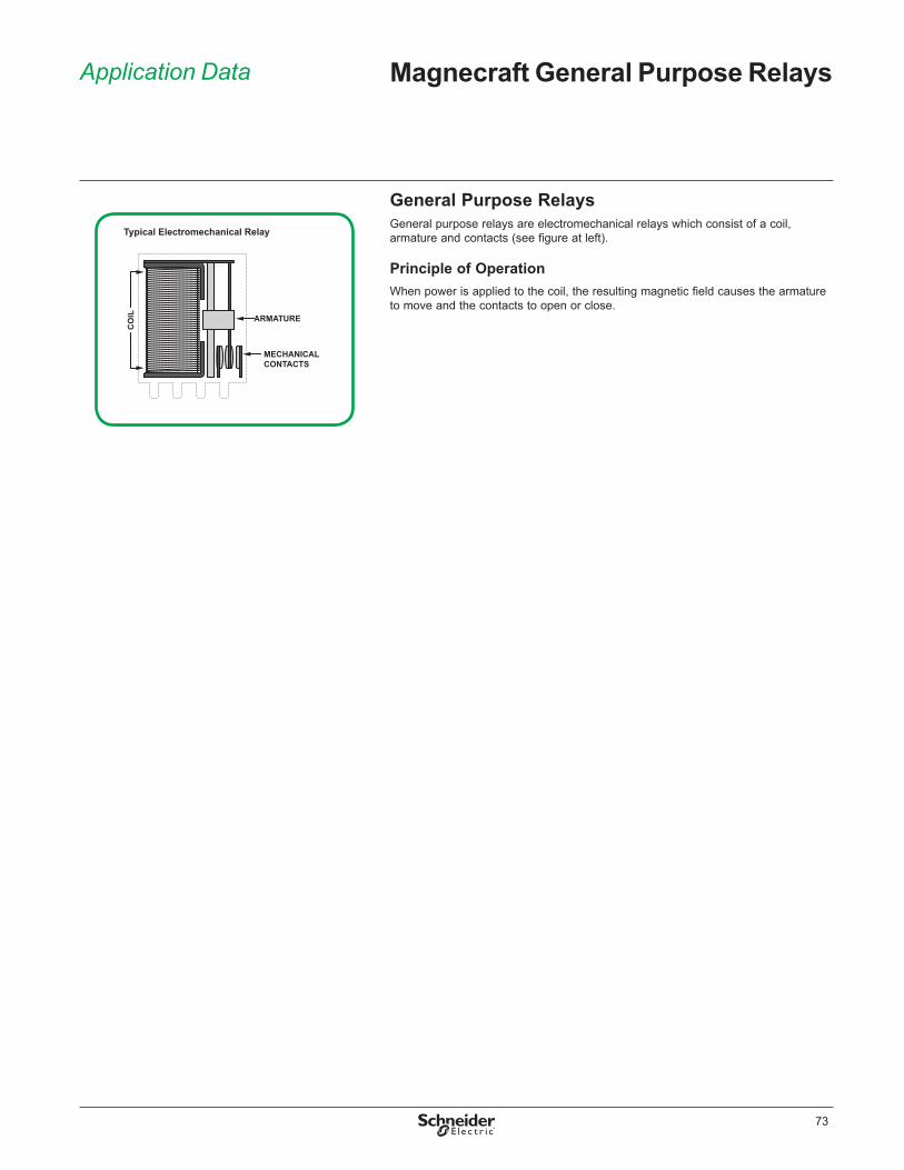
73
Application Data Magnecraft General Purpose Relays
General Purpose RelaysGeneral purpose relays are electromechanical relays which consist of a coil, armature and contacts (see figure at left) .
Principle of OperationWhen power is applied to the coil, the resulting magnetic field causes the armature to move and the contacts to open or close .
MECHANICALCONTACTS
Typical Electromechanical Relay
CO
IL ARMATURE

74
ApplicationsWith multiple options, features and available accessories, Magnecraft general purpose relays offer a complete system solution to improve your design, expedite installation and simplify testing of your application .
Application Data (continued) Magnecraft General Purpose Relays
Automation PanelsProcess controls, motor controls, standby lighting
Power SuppliesUniversal power supplies, battery backup systems
AppliancesAir conditioners, water heaters, portable heaters, spa controls, water pumps
Packaging MachineryConveyor motors, food processors, product/shrink wrap, solenoid controls
Material HandlingMotor control, conveyor controls
HVAC & RefrigerationAnti-condensation equipment, compressor controls, blower controls, motorized duct/vent controls
Lighting ControlTraffic signal systems, motorway information systems, theatrical lighting, ballast lighting
Food & BeverageCommercial/industrial cooking equipment, filtration systems, bottling, chillers, convection ovens
Typical Examples of General Purpose Relay Applications
75
The Magnecraft website (www.serelays.com) is designed to enable users to easily find the proper relay to fit design requirements and to help simplify and shorten workflow .
Easily find the proper relay to fit design requirements
b Online CatalogFind the right product by choosing specifications, compare products side-by-side, and view technical specifications, 2D and 3D drawings, and associated accessories .
b Cross Reference SearchSearch our comprehensive database to identify products by manufacturer and part number, and link directly to part specifications .
b 3D CAD LibraryView, email, download, or insert a file directly into your open CAD software . There are 18 different file formats to choose from .
b Order Free SamplesMagnecraft offers free samples as a courtesy to individuals and companies evaluating our products for their designs and applications . Sample orders are subject to approval .
Simplify and shorten workflow
b Interactive ToolsView interactive demonstrations; such as our Time Delay Relay Interactive Demo (left) which visually demonstrates the ten different timing functions offered on Magnecraft time delay relays .
b Distributor Inventory SearchSearch authorized distributors’ current Magnecraft inventory and buy online . (Buy online not available for all distributors) .
Website Guide Magnecraft General Purpose Relays
Time Delay Relay Demo
3D Models

Electrical equipment should be installed, operated, serviced, and maintained only by qualified personnel . No responsibility is assumed by Schneider Electric for any consequences arising out of the use of this material .
© 2012–2014 Schneider Electric . All Rights Reserved . Schneider Electric and Fingersafe are trademarks owned by Schneider Electric Industries SAS or its affiliated companies. All other trademarks are the property of their respective owners.
8501CT1105R09/14, 09/2014Replaces 8501CT1105R08/13 dated 02/2014
Schneider Electric USA, Inc.1300 S . Wolf Rd .Des Plaines, IL 60018Tel: 847-441-2540www .serelays .com


