
Maneuvering, Aeroelasticity,
and Control InteractionsRobert Stengel, Aircraft Flight Dynamics
MAE 331, 2008
• High angle of attackand angular rates
• Nonlinearaerodynamics
• Inertial coupling
• Fuel sloshing
• Aeroelasticity
• Rudder lock
Copyright 2008 by Robert Stengel. All rights reserved. For educational use only.http://www.princeton.edu/~stengel/MAE331.html
http://www.princeton.edu/~stengel/FlightDynamics.html
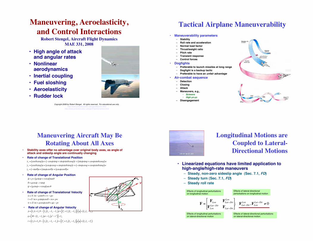
Tactical Airplane Maneuverability
• Maneuverability parameters– Stability
– Roll rate and acceleration
– Normal load factor
– Thrust/weight ratio
– Pitch rate
– Transient response
– Control forces
• Dogfights– Preferable to launch missiles at long range
– Dogfight is a backup tactic
– Preferable to have an unfair advantage
• Air-combat sequence– Detection
– Closing
– Attack
– Maneuvers, e.g.,• Scissors
• High yo-yo
– Disengagement
Maneuvering Aircraft May Be
Rotating About All Axes
!
˙ u = X /m " gsin# + rv " qw
˙ v = Y /m + gsin$ cos# " ru + pw
˙ w = Z /m + gcos$ cos# + qu " pv
!
˙ p = IzzL + IxzN " Ixz Iyy " Ixx " Izz( )p + Ixz
2 + Izz Izz " Iyy( )[ ]r{ }q( ) ÷ IxxIzz " Ixz
2( )
˙ q = M " Ixx " Izz( )pr " Ixz p2" r
2( )[ ] ÷ Iyy
˙ r = IxzL + IxxN " Ixz Iyy " Ixx " Izz( )r + Ixz
2 + Ixx Ixx " Iyy( )[ ]p{ }q( ) ÷ IxxIzz " Ixz
2( )
!
˙ x I = cos" cos#( )u + $cos% sin# + sin% sin" cos#( )v + sin% sin# + cos% sin" cos#( )w
˙ y I = cos" sin#( )u + cos% cos# + sin% sin" sin#( )v + $sin% cos# + cos% sin" sin#( )w
˙ z I = $sin"( )u + sin% cos"( )v + cos% cos"( )w
!
˙ " = p + qsin" + rcos"( ) tan#
˙ # = qcos" $ rsin"
˙ % = qsin" + rcos"( )sec#
• Rate of change of Translational Position
• Rate of change of Angular Position
• Rate of change of Translational Velocity
• Rate of change of Angular Velocity
• Stability axes offer no advantage over original body axes, as angle ofattack and sideslip angle are continually changing
Longitudinal Motions are
Coupled to Lateral-
Directional Motions
!
F =FLon
FLat"DirLon
FLon
Lat"DirFLat"Dir
#
$ %
&
' ( ; FLat"Dir
Lon,F
Lon
Lat"Dir ) 0
Effects of longitudinal perturbationson longitudinal motion
Effects of longitudinal perturbations
on lateral-directional motion
Effects of lateral-directional
perturbations on longitudinal motion
Effects of lateral-directional perturbations
on lateral-directional motion
• Linearized equations have limited application tohigh-angle/high-rate maneuvers– Steady, non-zero sideslip angle (Sec. 7.1, FD)
– Steady turn (Sec. 7.1, FD)
– Steady roll rate

Effects of Nominal Sideslip
and Angle of Attack
Effects of Nominal Sideslip
and Roll Rate
Pitch-Yaw Coupling Due
To Steady Roll Rate• Assume
– Body axes
– Roll rate = constant = po, rad/s
– Consider only pitching and yawing motions
!
"u(t) =
"#E
"#A
"#R
$
%
& & &
'
(
) ) )
Elevator, deg or rad
Ailerons, deg or rad
Rudder, deg or rad
!
"˙ x Lon
"˙ x LD
#
$ %
&
' ( =
FLon
FLD
Lon
FLon
LDFLD
#
$ %
&
' ( "x
Lon
"xLD
#
$ %
&
' ( +
GLon
GLD
#
$ %
&
' ( "u
!
"x(t) ="xLon
"xLD
#
$ %
&
' ( =
"w
"q
"v
"r
#
$
% % % %
&
'
( ( ( (
Normal velocity, m/s
Pitch rate, rad/s
Side velocity, m/s
Yaw rate, rad/s
• Control input vector
• 4th-order dynamic model
• State vector
Pitch-Yaw Coupling Due
To Steady Roll Rate
!
FLon FLDLon
FLonLD
FLD
"
# $
%
& ' =
Zw uo
Mw Mq
"
# $
%
& '
(po 0
0Izz ( Ixx( )Iyy
po
"
#
$ $ $
%
&
' ' '
po 0
0Ixx ( Iyy( )Izz
po
"
#
$ $ $
%
&
' ' '
Yv –uo
Nv Nr
"
# $
%
& '
"
#
$ $ $ $ $ $ $
%
&
' ' ' ' ' ' '
• 4th-order stability matrix with
– Neglible vo
– Negligible coupling aerodynamic effects
Pitch-Yaw Coupling Due
To Steady Roll Rate
!
" rolling s( ) = s# Zw( ) s#Mq( ) # uoMw[ ] s#Yv( ) s# Nr( ) + uoNv[ ]{ }
+ po2
s#Mq( ) s# Nr( ) # s# Zw( ) s#Yv( )Izz # Ixx( )Iyy
Ixx # Iyy( )Izz
# uoMw
Ixx # Iyy( )Izz
# uoNv
Izz # Ixx( )Iyy
$ % &
' &
( ) &
* &
# po4Izz # Ixx( )Iyy
Ixx # Iyy( )Izz
• 4th-order stability matrix with
– Neglible vo
– Negligible coupling aerodynamic effects
• Coupling effect is proportional to po2 and po
4
• Therefore, it is independent of the sign of po2
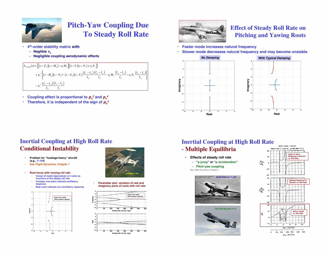
Effect of Steady Roll Rate on
Pitching and Yawing Roots
• Faster mode increases natural frequency
• Slower mode decreases natural frequency and may become unstable
No Damping With Typical Damping
Inertial Coupling at High Roll Rate
Conditional Instability
• Problem for “fuselage-heavy” aircraft(e.g., F-104)
• See Flight Dynamics, Chapter 7
• Root locus with varying roll rate– Values of mode eigenvalues (or roots) as
functions of the steady roll rate
– Complex root pairs indicate oscillatoryresponse
– Real roots indicate non-oscillatory response
• Parameter plot: variation of real andimaginary parts of roots with roll rate
Lockheed F-104
Dutch roll: solid
Short period: dashed
Dutch roll: solid
Short period: dashed
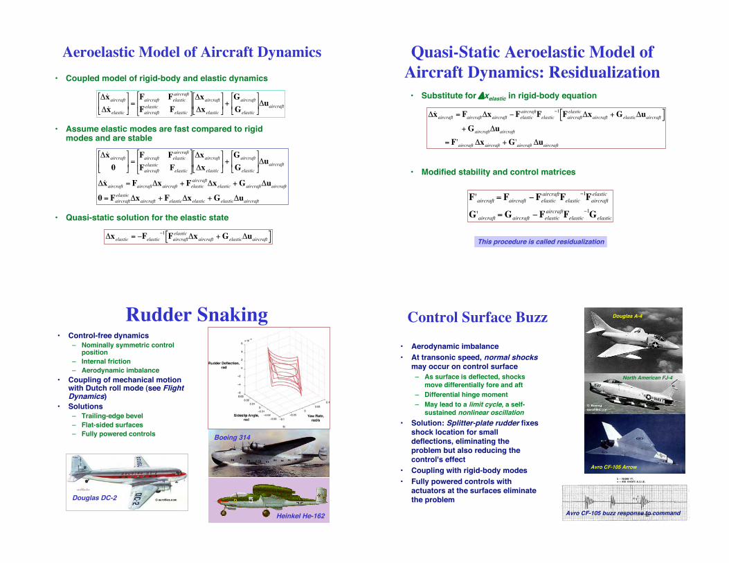
• Effects of steady roll rate
– “p jump” or “p acceleration”
– Pitch-yaw coupling• See Flight Dynamics, Chapter 7
Aileron Anglevs. Roll Rate
Sideslip Response toElevator vs. Roll Rate
Angle of AtackResponse to Elevatorvs. Roll Rate
Inertial Coupling at High Roll Rate
- Multiple Equilibria
North American F-100
Fairchild-Republic A-10

Tumbling, Spins, and Recovery
• Strong nonlinear effects
• Aircraft-specific control strategy for recovery
Stalls and Spins
• Sidney B. Gates, RAE: "The Spinning of Aeroplanes" (with L.W. Bryant,
1926), neutral and maneuver points, stick force per g
• Continued research on stalls and spins at NASA, USAF, and in manyother countries
NASA Langley Spin Tunnel
Tails with Negative
Dihedral (Anhedral)
• Horizontal tail belowwing's wake
• May have adverseeffect on spin
characteristics
McDonnell F-4
Spin rate, !b/2V
Yaw coefficient,Cn
Yawing Moment at High Angle of Attack
• Dynamic as well as staticeffects,e.g., hysteresis
• Random asymmetric yawingmoments
– generated by slender noseat zero sideslip angle
– may exceed rudder controlpower
F-111
F-4
F-104
Fairchild-Republic A-10

Controlling Yawing Moment at High
Angle of Attack• Sucking, blowing, or movable
strakes to control nose vortices
• X-29, F/A-18 HARV
• Vortex bursting effect on tail
Grumman X-29
McDonnell-Douglas F/A-18
McDonnell-Douglas F/A-18
Deep Stall• Pitch equilibrium point at high angle
of attack
• T-tail effect: as angle of attackincreases, tip vortices are
– not only in the plane of the tail,
– but the spanwise location is closerto the centerline due to tip stall,
increasing the effect
• Other aerodynamic origins
Learjet 23
General Dynamics F-16
Supermaneuverability• Means of forcing opponent to
overshoot
• Pugachev!s Cobra maneuver,first done in Sukhoi Su-27
• Beneficial effect of thrust-vectorcontrol (X-31)
• Mongoose maneuver (X-31)
Naval Aviation• Takeoff from steam catapult at full
power, elevator up, high g (F/A-18)
• Landing at full power, no flare, needto capture tail hook, follow preciseglide slope, pitching deck,superstructure wake turbulence(EA-6B)
• T-45 takeoff and landing

Propeller-Driven Aircraft
• Takeoff without catapult, relativelylow landing speed
• Tailhook and arresting gear
• Carrier steams into wind
• Design for storage (short tail length,folding wings) affects stability andcontrol
• Chance-Vought F4U Corsair
Early Carrier Jets• Problems exacerbated for jet
aircraft
– slower thrust response
– higher approach speeds
– reduced phugoid damping
– lower lift-slope wings
– higher angles for trim
McDonnell FH-1 Banshee
McDonnell F3H-1 Demon
North American FJ-2 Fury
Vought F7U Cutlass
Grumman F9F Panther
Sea Planes: Flying Boats and Hydroskis
• No need for runways
• Sea state
• Corrosion
• Added weight
• Unstick
Convair XF2Y Sea Dart
Martin XP6M Seamaster
Lockheed PBY Catalina
Marttin PBM Mariner Martin PB2M Mars
Interesting, Cancelled Naval Aircraft
Chance-Vought V-173 Grumman XF5FDouglas F6D Missileer
Rockwell International XFV-12A
Grumman XF12F
General Dynamics/McDonnell-Douglas A-12Avenger II

Direct-Lift Control-Approach
Power Compensation
• F-8 Crusader– Variable-incidence wing to
provide better pilot visibility
– Flight path control at lowapproach speeds requires throttleuse, could not be made with pitchcontrol alone
– Engine response time is slow
– Flight test of direct lift control(DLC), using the ailerons as flaps
• Approach power compensationfor A-7 Corsair II and direct liftcontrol were studied at Princetonusing our Variable-ResponseResearch Aircraft
Princeton VRA
Vought A-7
Vought F-8
Direct-Lift/Drag Control
• Direct-lift control installed onS-3A Viking– Implemented with spoilers
and beeper button
– Rigged “up” during landingto allow ± lift.
• Speed brakes on T-45AGoshawk make up for slowspool-up time of jet engine
– Derivative of BritishAerospace Hawk
– Hawk's speed brake moved tosides for carrier landing
– Idle speed increased from55% to 78% to allow moreeffective modulation viaspeed brakes
Lockheed S-3A
Boeing T-45
Ground Effect
• Close proximity to the ground
– downwash is impeded
– lift is increased
• Complex effects on lift,pitching moment, and rollingmoment (see Flight Dynamics)
• Analysis models the effect bya mirror image of the aircraft
• Analogous to wind-tunnel wallcorrections
Concorde
• Coupling of non-rigid dynamic modes with rigid-body modes
• Resonant response
– Dynamically coupled modes of motion with similar frequencies
– With light damping, oscillatory amplitudes may become large
• Coupling between longitudinal and lateral-directional effects
• Nonlinear aerodynamics
• Floating control surfaces, high hinge moments, and high
aerodynamic angles
Fuel Slosh and
Aeroelasticity
!
"˙ x aircraft
"˙ x elastic
"˙ x slosh
#
$
% % %
&
'
( ( (
=
Faircraft Felastic
aircraftFslosh
aircraft
Faircraft
elasticFelastic Fslosh
elastic
Faircraft
sloshFelastic
sloshFslosh
#
$
% % %
&
'
( ( (
"xaircraft
"x elastic
"x slosh
#
$
% % %
&
'
( ( (
+ G"u

Fuel Shift
• Problem with partially filled fuel tank
• Single wing tank from tip to tip (A4D)
• Slow, quasi-static shift of fuel c. m.
• Rudder step throws fuel to one side,producing a strong rolling moment
(A4D)
Fuel Slosh• Dynamic oscillation of fuel center of mass,
wave motion at the fuel's surface
• Pendulum and spherical-tank analogies
• Fore-aft slosh in wing-tip tanks coupledwith the short period mode (P-80)
• Fuselage tank forward of the aircraft'scenter of mass (A4D)
– Yawing motion excites oscillatory slosh thatcouples with Dutch roll mode
• Solution: Fuel-tank baffles– Slow down fuel motion
– Force resonances to higher frequencies dueto smaller cavities
– Wing internal bracing may act as baffle
Lockheed P-80 Shooting Star(A4D)
Aeroelastic Problems of the Lockheed Electra• Prop-whirl flutter, 2 fatal accidents (1959-60)
• Structural modifications made; aircraft remained in service until 1992
• Predecessor of US Navy Orion P-3, still in service
Aeroelastic Problems are Analogous to Oscillatory Slosh

Reduced Aileron Effect
Due to Aeroelasticity
• Wing torsionreduces aileroneffect withincreasing dynamicpressure
Rolling Criterion,pb/2V
pb/2Velastic / pb/2Vrigid
Republic P-47 Thunderbolt Longitudinal
Structural Modes of
Boeing 2707-300
Supersonic Transport
Boeing 2707-300
NormalizedDeflection
Centerline station
Aeroelastic Aileron Effect of
Boeing 2707-300 Supersonic
TransportBoeing 2707-300
Elastic-to-Rigid Ratio
Mach Number
B-1 Canards for Ride Control
• Elastic modes cause severe, high-g cockpit vibration during low-altitude, high-speed flight
• Active canard surfaces reduce amplitude of the oscillations
Aeroelastic Model of Aircraft Dynamics
!
"˙ x aircraft
"˙ x elastic
#
$ %
&
' ( =
Faircraft Felastic
aircraft
Faircraft
elasticFelastic
#
$ %
&
' ( "xaircraft
"x elastic
#
$ %
&
' ( +
Gaircraft
Gelastic
#
$ %
&
' ( "uaircraft
!
"˙ x aircraft
0
#
$ %
&
' ( =
Faircraft Felastic
aircraft
Faircraft
elasticFelastic
#
$ %
&
' ( "xaircraft
"x elastic
#
$ %
&
' ( +
Gaircraft
Gelastic
#
$ %
&
' ( "uaircraft
"˙ x aircraft = Faircraft"xaircraft + Felastic
aircraft"x elastic + Gaircraft"uaircraft
0 = Faircraft
elastic"xaircraft + Felastic"x elastic + Gelastic"uaircraft
!
"x elastic = #Felastic#1Faircraftelastic
"xaircraft +Gelastic"uaircraft[ ]
• Coupled model of rigid-body and elastic dynamics
• Assume elastic modes are fast compared to rigidmodes and are stable
• Quasi-static solution for the elastic state
Quasi-Static Aeroelastic Model of
Aircraft Dynamics: Residualization
!
"˙ x aircraft = Faircraft"xaircraft #Felastic
aircraftFelastic
#1
Faircraft
elastic"xaircraft + Gelastic"uaircraft[ ]
+ Gaircraft"uaircraft
= F'aircraft "xaircraft + G'aircraft "uaircraft
!
F'aircraft = Faircraft "Felasticaircraft
Felastic"1Faircraftelastic
G'aircraft =Gaircraft "Felasticaircraft
Felastic"1Gelastic
• Substitute for "xelastic in rigid-body equation
• Modified stability and control matrices
This procedure is called residualization
Rudder Snaking• Control-free dynamics
– Nominally symmetric controlposition
– Internal friction
– Aerodynamic imbalance
• Coupling of mechanical motionwith Dutch roll mode (see FlightDynamics)
• Solutions
– Trailing-edge bevel
– Flat-sided surfaces
– Fully powered controls
Heinkel He-162
Douglas DC-2
Boeing 314
Control Surface Buzz
Avro CF-105 buzz response to command
• Aerodynamic imbalance
• At transonic speed, normal shocksmay occur on control surface
– As surface is deflected, shocksmove differentially fore and aft
– Differential hinge moment
– May lead to a limit cycle, a self-sustained nonlinear oscillation
• Solution: Splitter-plate rudder fixesshock location for smalldeflections, eliminating theproblem but also reducing the
control's effect
• Coupling with rigid-body modes
• Fully powered controls with
actuators at the surfaces eliminatethe problem
Douglas A-4
North American FJ-4
Avro CF-105 Arrow

Rudder Lock• Rudder deflected to the stops at high
sideslip angle, in turn, trims the
aircraft at the high angle
• 3 necessary ingredients
– Low directional stability at highsideslip angle, induced by stalling ofthe vertical fin
– High (positive) hinge moment-due-to-sideslip at high sideslip (e.g., B-26)
– Strong negative yawing moment ofrudder
• Problematical if rudder is unpoweredand requires high foot-pedal force(e.g., “rudder float” of large WWIIaircraft)
• Solutions
– Increase high-sideslip directionalstability by adding a dorsal fin (e.g.,B-737-100 (before), B-737-400 (after))
– Hydraulically powered rudder
Martin B-26
Boeing 737-100
Boeing 737-400
DC-3 Rudder Lock• Solutions to rudder lock
– Increase high-sideslip directionalstability by adding a dorsal fin
– Hydraulically powered rudder
• DC-3 still had rudder lock afteradding dorsal
• Super DC-3 (R4D-4+) entirelydifferent vertical tail design
Next Time:High Speed and Altitude


