
MARINE ACCIDENT REPORTSeptember 2016
UMOE VENTUSFire on 23 December 2015

Page 2 of 45
This marine accident report is issued on 19 September 2016.
Front page: Picture of SES. Source: Umoe Mandal AS.
The marine accident report is available from the website of the Danish Maritime Accident In-
vestigation Board (www.dmaib.com).
The Danish Maritime Accident Investigation Board
The Danish Maritime Accident Investigation Board is an independent unit under the Ministry
of Business and Growth. It carries out investigations as an impartial unit that is, organizational-
ly and legally, independent of other parties. The board investigates maritime accidents and oc-
cupational accidents on Danish and Greenland merchant and fishing ships, as well as accidents
on foreign merchant ships in Danish and Greenland waters.
The Danish Maritime Accident Investigation Board investigates about 140 accidents annually.
In case of very serious accidents, such as deaths and losses, or in case of other special circum-
stances, either a marine accident report or a summary report is published, depending on the
extent and complexity of the events.
The investigations
The investigations are carried out separately from the criminal investigation, without having
used legal evidence procedures and with no other basic aim than learning about accidents with
the purpose of gaining and promoting an understanding of safety. Consequently, any use of
this report for other purposes may lead to erroneous or misleading interpretations.
The Danish Maritime Accident Investigation Board Carl Jacobsens Vej 29 DK-2500 Valby Denmark Tel. +45 72 19 63 00 Email: [email protected] Website: www.dmaib.com Outside office hours, the DMAIB can be reached on +45 23 34 23 01.
Page 3 of 45
CONTENT
1. ABSTRACT ............................................................................................................................................................. 4
2. FACTUAL INFORMATION .......................................................................................................................... 5
2.1 Photo of the ship ............................................................................................................................................ 5
2.2 Ship particulars ................................................................................................................................................ 5
2.3 Voyage particulars ........................................................................................................................................... 6
2.4 Weather data .................................................................................................................................................... 6
2.5 Marine casualty or incident information ..................................................................................................... 6
2.6 Shore authority involvement and emergency response ............................................................................ 6
2.7 The ship’s crew ............................................................................................................................................... 6
2.8 Scene of the accident ...................................................................................................................................... 7
3. NARRATIVE OF THE ACCIDENT ........................................................................................................... 8
3.1 Background ...................................................................................................................................................... 8
3.2 Sequence of events ......................................................................................................................................... 9
Summary of the voyage from the shipyard in Norway to Bagenkop, Denmark ....................... 10 3.2.1
Departure from Bagenkop – the fire and the evacuation of the craft ........................................ 12 3.2.2
3.3 The wreck of UMOE VENTUS ................................................................................................................ 15
4. INVESTIGATION DATA .............................................................................................................................. 17
4.1 Description of craft’s certification and manning, design, firefighting .................................................. 17
equipment and emergency procedures ....................................................................................................................... 17
Certification and manning .................................................................................................................. 17 4.1.1
General description of UMOE VENTUS ...................................................................................... 18 4.1.2
General aspects of composite materials ........................................................................................... 20 4.1.3
Structural and functional fire protection on UMOE VENTUS .................................................. 26 4.1.4
Emergency procedures – fire and evacuation ................................................................................. 27 4.1.5
4.2 The time, origin, cause and spread of the fire .......................................................................................... 29
The time of the fire ............................................................................................................................. 29 4.2.1
The origin of the fire ........................................................................................................................... 30 4.2.2
The probable cause of the fire ........................................................................................................... 31 4.2.3
The spread of the fire ......................................................................................................................... 35 4.2.4
5. ANALYSIS ........................................................................................................................................................... 38
5.1 The cause of the fire ..................................................................................................................................... 38
5.2 The operation and management of the craft ............................................................................................ 38
5.3 UMOE VENTUS’ robustness towards fire ............................................................................................. 39
Structural and functional fire protection.......................................................................................... 40 5.3.1
Carbon fibre reinforced plastic sandwich bulkheads ...................................................................................... 40
The crew’s capacity to fight the fire ................................................................................................. 42 5.3.2
6. CONCLUSIONS ............................................................................................................................................... 42
7. PREVENTIVE MEASURES TAKEN ....................................................................................................... 44
8. APPENDICES .................................................................................................................................................... 45

Page 4 of 45
ABSTRACT 1. On 23 December 2015, a fire broke out on the prototype surface effect ship UMOE VEN-
TUS. The fire started in the port side lift fan compartment and within 15 minutes after the fire
was visually detected the craft was engulfed in flames and drifted uncontrollably until it
grounded in the shallow waters north of the harbour of Bagenkop, Denmark, and was lost.
The fire was caused by insufficient cooling of the lift fan engine exhaust system, which ignited
the exhaust muffler and/or the compartment where it was mounted. From the lift fan com-
partment the fire quickly spread outwards to the bulwark and accommodation and inwards to
the adjacent diesel oil tank. The insufficient cooling of the lift fan engine was likely caused by a
clogged sea chest strainer. There were several alarms on the cooling water system during arrival
and departure from Bagenkop, but the importance of the alarms was not acknowledged by the
crew due to events that had unfolded during the preceding days, which had created a tolerance
towards safety critical alarms.
After the discovery of the fire, the crew had no other option than to evacuate the craft without
any attempt to fight the fire manually and/or by means of the craft’s fixed firefighting systems.
The overall aim of the investigation was to establish why a failure of the cooling water system
led to an uncontrollable fire that resulted in a total loss of the craft. The focus of the investiga-
tion was UMOE VENTUS’ robustness towards fire.
It was found that the master worked in an environment of distributed authority – between the
charterer, the ship management organisation, and the owners. In the continuous communica-
tion with the shore-based technical and commercial management, the master was subjected to
other forms of authority that challenged his perception of his own authority on board the craft
which affected his judgement towards the seaworthiness of the craft.
The accident illustrated that it can be problematic to change a ship’s construction from a non-
combustible material to a combustible material by designing equivalent solutions based on tra-
ditional functional fire protection strategies. It was found that the concept of building the craft
as a combustible carbon composite structure with a relatively low ignition temperature, com-
pared to steel, reduced the craft’s robustness towards fire scenarios that were not considered
during the design and approval of the craft. Thereby, the fire shows the necessity of rethinking
the entire concept of the interaction between structural and functional fire protection, fire-
fighting and evacuation when changing the underlying premise of having the ship constructed
in a non-combustible material.
In order to increase robustness of the vessel, the shipyard has implemented measures on the
sister ship currently operating in wind farms and on existing and future new builds.

Page 5 of 45
Figure 1: UMOE VENTUS Source: Valling Ship Management ApS
FACTUAL INFORMATION 2.
2.1 Photo of the ship
2.2 Ship particulars
Name of vessel: UMOE VENTUS Type of vessel: Cargo ship Nationality/flag: Denmark Port of registry: Svendborg IMO number: 9758507 Call sign: OWNK2 DOC company: Valling Ship Management ApS IMO company no. (DOC): 5588065 Year built: 2014 Shipyard/yard number: Umoe Mandal AS Classification society: DNV-GL Length overall: 26.6 m Breadth overall: 10.4 m Gross tonnage: 233 Deadweight: 14.9 m Draught max.: 2.77 m (on cushion) Engine rating: 2x1,440 kW Service speed: 40 knots Hull material: Carbon Fibre Sandwich Hull design: Catamaran hull with an enclosed air cushion
Page 6 of 45
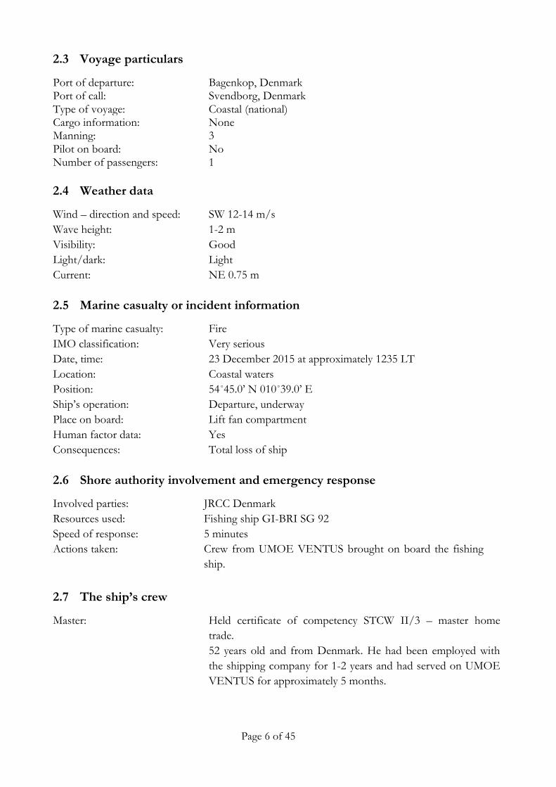
2.3 Voyage particulars
Port of departure: Bagenkop, Denmark Port of call: Svendborg, Denmark Type of voyage: Coastal (national) Cargo information: None Manning: 3 Pilot on board: No Number of passengers: 1
2.4 Weather data
Wind – direction and speed: SW 12-14 m/s
Wave height: 1-2 m
Visibility: Good
Light/dark: Light
Current: NE 0.75 m
2.5 Marine casualty or incident information
Type of marine casualty: Fire
IMO classification:
Date, time:
Very serious
23 December 2015 at approximately 1235 LT
Location: Coastal waters
Position: 54˚45.0’ N 010˚39.0’ E
Ship’s operation: Departure, underway
Place on board: Lift fan compartment
Human factor data: Yes
Consequences: Total loss of ship
2.6 Shore authority involvement and emergency response
Involved parties: JRCC Denmark
Resources used: Fishing ship GI-BRI SG 92
Speed of response: 5 minutes
Actions taken: Crew from UMOE VENTUS brought on board the fishing
ship.
2.7 The ship’s crew
Master: Held certificate of competency STCW II/3 – master home
trade.
52 years old and from Denmark. He had been employed with
the shipping company for 1-2 years and had served on UMOE
VENTUS for approximately 5 months.
Page 7 of 45
Navigational officer: Held certificate of competency STCW II/3 – mate.
44 years old and from Denmark. He had been employed with
the shipping company and had served on UMOE VENTUS for
approximately 1 year.
Able seaman (AB): Held certificate of competency as an able seaman.
34 years old and from the Philippines. He had been employed
with the shipping company and had served on UMOE VEN-
TUS for approximately 20 days.
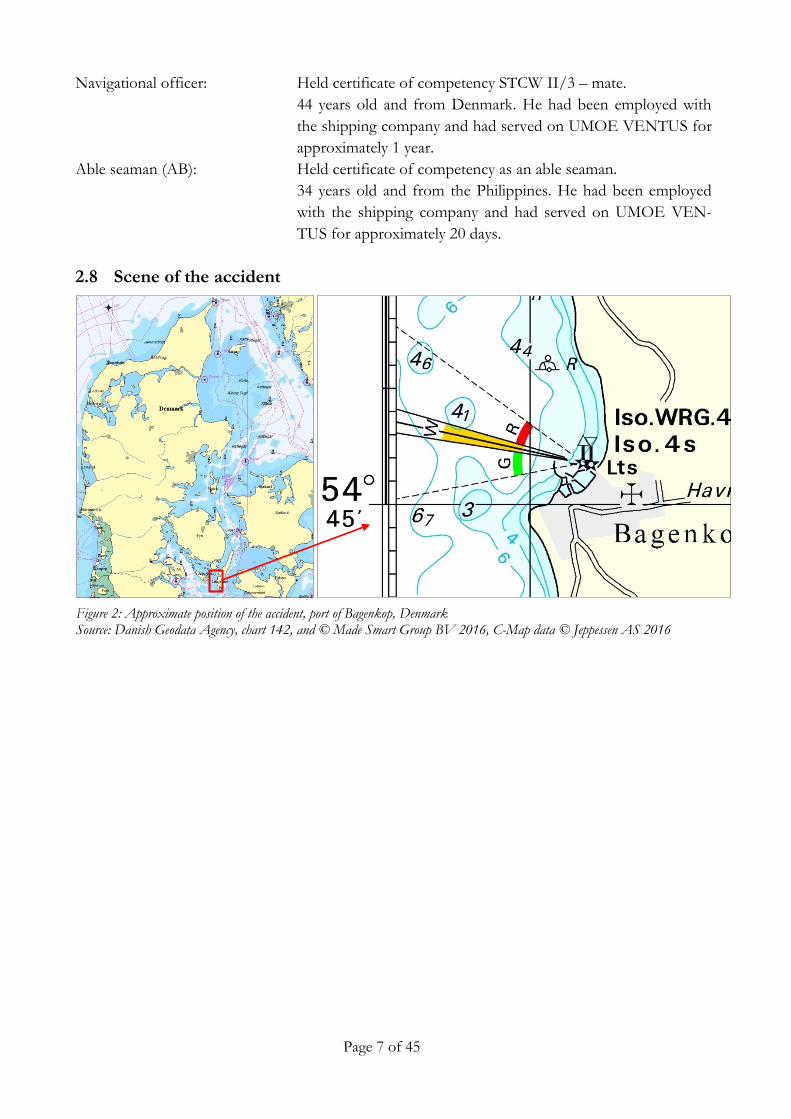
2.8 Scene of the accident
Figure 2: Approximate position of the accident, port of Bagenkop, Denmark Source: Danish Geodata Agency, chart 142, and © Made Smart Group BV 2016, C-Map data © Jeppessen AS 2016
Page 8 of 45
NARRATIVE OF THE ACCIDENT 3.
3.1 Background
UMOE VENTUS was built in 2014 as a purpose designed service craft for transporting service
teams of up to 12 persons to offshore wind farms, where it could act as a stable platform from
where personnel and equipment could be transferred to offshore wind turbines. The craft was
designed to be effective in adverse weather and wave conditions.
The craft was a prototype surface effect ship, i.e. a catamaran with an enclosed air cushion and
a twin water jet propulsion system, which enabled the craft to reach a speed of up to 40 knots.
The hull, various tanks and the superstructure of the craft were built as a carbon fibre rein-
forced plastic sandwich construction.
It was delivered to the owner in February 2015 and was put into operation in March 2015. Ini-
tially there were minor prototype problems that were solved on site by technicians from the
shipyard. However, the crew considered the craft to be an overall stable platform for transfer
of personnel and with good handling characteristics that made it function well as a wind tur-
bine offshore service craft.
UMOE VENTUS was in a charter in Norddeich from where the offshore wind farm Borkum
Riffgrund 1 was serviced. A ship management company acted both as agent for the owners
and manager of the craft.

Page 9 of 45
The narrative about the accident is in two parts: A summary of the voyage from the shipyard in
Norway to the location of the accident in Denmark, and a narrative about the fire and the evac-
uation of the craft. The narrative is presented from the perspective of the crew of UMOE
VENTUS as the events unfolded. Statements of time are given in local time in Denmark
(UTC+1), unless otherwise specified.
See figure 3 for an overview of the time and location for the main events prior to the accident.
Figure 3: Overview of time and location of the main events prior to the accident Source: DMAIB and © Made Smart Group BV 2016, C-Map data © Jeppessen AS 2016
3.2 Sequence of events
Page 10 of 45
Summary of the voyage from the shipyard in Norway to Bagenkop, Denmark 3.2.1
UMOE VENTUS had been at a shipyard in Mandal, Norway, from September until December
2015 mainly for repairing a damaged transmission, but other minor modifications were also
made on the craft. During December the crewmembers arrived at the shipyard for familiariza-
tion with the craft’s modifications and training in the use of the craft’s control systems.
On the morning of 19 December 2015, after all final tests had been made by the shipyard and
the approval by the classification society had been concluded, the craft departed from the ship-
yard in Mandal bound for Norddeich, Germany, where a few days later it was to be put into
service carrying service personnel to offshore wind farms. The voyage to Germany was to be
made through Danish waters and via the Kiel Canal because the weather forecast predicted
unfavourable weather conditions in the North Sea. The plan was to reach the Kiel Canal the
same day giving the crew an opportunity to rest.
Upon departure the crew consisted of two Danish deck officers and one Filipino able seaman
(AB). Additionally, there were nine passengers from the shipyard, sales representatives, poten-
tial customers and crewmembers from a sister ship, who were on board to be familiarized with
the craft. They were to be disembarked upon arrival at the Kiel Canal. One warranty engineer
from the shipyard was on board to act as a liaison between the ship and the shipyard should
any technical problems arise. He was to be on board until the craft had reached Norddeich.
Approximately eight hours after departure from Norway and shortly before passing the Skaw,
Denmark, the craft experienced technical problems with one of the craft’s vent valves for regu-
lating the air pressure in the air cushion. The shipyard deemed it necessary to divert from the
voyage plan and go to the port of Frederikshavn, Denmark, for repairs and spare parts from
the shipyard. Shortly after arrival all the passengers, except the warranty engineer, disembarked.
After the repairs of the regulating valve and subsequent testing had been completed, the pas-
sengers, except the warranty engineer from the shipyard, disembarked. Two days later, on 21
December 2015 at approximately 1600, UMOE VENTUS departed from Frederikshavn with
three crewmembers and the warranty engineer.
Shortly after departure, the starboard side main propulsion engine malfunctioned and another
regulating valve for the air cushion system was not functioning according to the specifications.
It was once again decided to divert from the voyage plan and go to the port of Nyborg, Den-
mark, and wait for a service technician to arrive from Norway. He was to repair the main en-
gine and monitor the propulsion system while en route to the Kiel Canal.
Shortly after midnight on 22 December, UMOE VENTUS arrived in Nyborg. The AB and the
warranty engineer went ashore to a hotel and rested, while the master and mate stayed on the
craft.

Page 11 of 45
The following day, the main engine service technician arrived and repaired the engine. Other
necessary adjustments of the ship's air cushion systems were made by the warranty engineer
from the shipyard.
The following day, 22 December at midday, UMOE VENTUS departed from Nyborg with the
warranty engineer and main engine technician on board.
While southbound along the east coast of Langeland, Denmark, the crew tried to pump ballast
into the starboard side ballast tank, but no content could be observed in the tank. After a
while, the ship got a 4-7 degree list to starboard. A bilge alarm was shortly after activated in a
compartment under the starboard side lift fan engine room. The warranty engineer went to the
lift fan engine room compartment to open a man-hole cover to inspect the compartment (dry
tank) and found approximately 7-8 m3 of seawater in the compartment, which was adjacent to
the ballast tank. The crew tried to pump out the water using the bilge pump, but the water lev-
el did not diminish and kept rising. The crew were uncertain about where the seawater came
from and considered the likelihood of the craft losing buoyancy and foundering. The crew
decided to divert from the voyage plan and proceed to the nearest port which was the small
harbour of Bagenkop, Denmark, to assess the situation in the engine compartments and pump
out the seawater.
During the arrival, as the craft was passing the breakwater, there were several engine system
alarms including on the port side seawater cooling water system, none of which the crew rec-
ognized to be critical because focus was on bringing the craft alongside and stopping the in-
gress of seawater.
In the afternoon of 22 December 2015 at approximately 1530, UMOE VENTUS arrived in
Bagenkop and the main engine technician, who had completed repairs on the main engine,
disembarked the craft. Immediately after arrival, the crew inspected the compartments below
deck. The master and the AB found that a man-hole cover on a ballast tank had not been
properly fitted and that the seawater came from the open ballast water tank. During the after-
noon/evening the water was pumped out using the craft’s bilge pumps assisted by a portable
pump which was brought on board by a representative from the ship management company,
which was located in the nearby port of Svendborg.
During the same evening the crew established that the engine alarm system showed multiple
alarms. They showed it to the ship management representative and they agreed that the ship
was not in a stable and reliable condition. By then it was evident to the master that it would
not be possible to reach Norddeich within the specified timeframe, and therefore the port call
was cancelled. It was, however, not convenient to stay in Bagenkop harbour because it was not
a commercial port, it was remote and did not have the necessary facilities for the crew. There-
fore, the crew agreed with the ship management company that they should proceed to the larg-
er commercial port of Svendborg, Denmark, to stay during Christmas and order a repair team

Page 12 of 45
from the shipyard which could attend to the multiple engine system alarms and see to the bal-
last system that had caused partial flooding of the dry-tank.
On the morning of 23 December, the master had a conversation with the warranty engineer
and insisted that the main seawater cooling system filters be inspected before departure. The
filters were inspected and found to be clean. The sea chest strainers were not checked because
it was deemed unlikely that they were clogged because the mesh size was large. The fault that
prompted the alarms on the seawater cooling system was not identified.
Departure from Bagenkop – the fire and the evacuation of the craft 3.2.2
Upon departure from Bagenkop, the bridge was manned by the master who stood by the star-
board side conning station. The mate and the AB were on deck handling the gangway and
mooring lines. The master let the ship drift into the harbour basin and waited until the crew
had finished his work on deck. As the AB and mate arrived on the bridge, the master moved to
the port side conning station and increased power on the propulsion and departed from the
harbour at 1209.
Suddenly a large number of alarms were activated, including on the main engine cooling water
system. The master immediately reduced power on the propulsion engines, and the mate went
below deck where he inspected the various parts of the cooling water system and found that
the cooling water inlet pipe was cold indicating that it was in working order. The warranty en-
gineer from the shipyard heard the alarm and came to the bridge where he observed that there
was low pressure (below 1 bar) on the seawater cooling system. The master suspected that the
seawater filter was clogged and activated the back-flushing mechanism on the sea chest intake.
A few minutes later a high temperature alarm was activated on the port side lift fan engine, and
the mate stopped it and left the starboard lift fan engine running. The mate went to the engine
room compartments again and reported that he sensed a smell of overheating.
The mate and the technician had a short conversation with the master about returning to port,
and they agreed that they had to return to Bagenkop harbour to inspect the various systems for
any malfunctions.
Approximately ten minutes later as the master turned the ship to port and increased the pro-
pulsion power, a large cloud of black smoke from the port side engulfed the wheelhouse. The
master immediately shut down the propulsion engines, looked out of the windows on the port
side of the bridge and saw 1.5 metre high flames above the gunwale on the upper deck (figure
4). Shortly after the flames were observed, a fire detector alarm sounded from within the ac-
commodation.

Page 13 of 45
Figure 4: Port side of UMOE VENTUS. Source: Private photo
Area with flames as witnessed by the master
The fire spread rapidly, and the smoke made it hazardous to stay on the craft. The master and
crew quickly realized that the fire was so intense that it would be meaningless to initiate fire-
fighting – focus was on evacuating the craft as quickly as possible. He announced to the crew
that they had to evacuate the craft. He immediately made a distress call on the VHF’s channel
16 at 1236. The coast radio station Lyngby Radio responded to the emergency call and relayed
the distress message to ships in the area. Within two minutes two local fishing vessels respond-
ed and departed from Bagenkop harbour. At this point, the fire on UMOE VENTUS was in-
tense and covered the accommodation on the port side.
While the master was busy with the communication, the crew prepared to evacuate the craft.
The mate and the technician went to the deck and launched the life raft, inflated it and lashed
it to the aft part of the deck. When the master heard on the radio that two fishing vessels were
proceeding to the position of UMOE VENTUS, he and the AB took the immersion suits and
life-jackets and threw them from the bridge to the aft deck. The master brought an emergency
VHF so he could communicate with the approaching fishing vessels.
Before the mate left the craft, he went to the bridge in an attempt to activate the foam extin-
guishing system, but the smoke was so intense that he considered it too hazardous to enter the
wheelhouse. The attempt was therefore abandoned.
At the time of the fire, there were 1.5-2.0 metre waves, which made it difficult to keep the in-
flated life raft steady alongside. The master’s initial plan was to wait for the approaching fishing
vessels to get alongside UMOE VENTUS. While waiting for the fishing vessels, the crew
Page 14 of 45
donned the immersion suits, whereafter the master and mate went to the forecastle to assess
the situation. By this time most of the port side of the accommodation was in flames and
through the windows the master saw flames in the passenger lounge. The fire quickly became
so intense that they decided to evacuate the craft before the fishing vessels arrived.
The crew tried to push the life raft from UMOE VENTUS, but the life raft got stuck under
the aft part of UMOE VENTUS that pitched in the 1.5 metre waves. Water gushed into the
life raft, but after several attempts the crew managed to free the life raft from the craft and it
started to drift away. At this point in time the accommodation of UMOE VENTUS was en-
gulfed in flames and smoke, and the entire port side structure of the hull had been destroyed.
A few minutes later, the life raft came alongside a fishing vessel from Bagenkop and the crew,
assisted by the fishermen, embarked the fishing vessel. At 1257, the master called the company
from the wheelhouse of the fishing vessel and informed them about the situation. The crew
was brought to the hospital in Svendborg, Denmark, for observation for smoke poisoning.
Approximately 20 minutes passed from the time the fire was discovered until the crew were on
board the fishing vessel.
Page 15 of 45
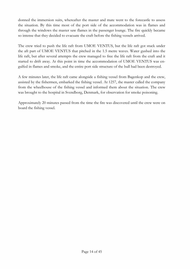
Figure 5: Starboard side of UMOE VENTUS shortly after the grounding Source: TV2/Danmark A/S
3.3 The wreck of UMOE VENTUS
When the craft had been abandoned, it drifted in the area north of the harbour of Bagenkop
for several hours before it grounded in an area of shallow water north of the harbour. The fire
developed a large amount of smoke that drifted inland and towards the town of Bagenkop.
The police authorities therefore urged the citizens to stay indoors until the fire had been extin-
guished.
The wreck was located approximately 60 metres from shore and it was therefore not possible
for the shore-based fire services to extinguish the fire. The fire was extinguished when the
structure of the craft had been damaged to the extent that all buoyancy was lost approximately
12 hours later, and it was almost submerged in the shallow water (figure 5).
On 17 February 2016, the wreck of UMOE VENTUS was salvaged in several pieces. About
half of the craft was salvaged as smaller pieces of debris. The wreck was brought to the port of
Horsens, Denmark, on 23 February 2016 where an investigation of the wreck was conducted.
It was apparent that the fire and the exposure to the sea had caused a complete structural
breakdown of the craft. The fire had destroyed the accommodation, the main deck and most
of the port side hull. The starboard side hull had also suffered a structural breakdown, but
some sections of the bulwark were still complete. During the salvage, the remains of the port
side hull were placed on top of the starboard side hull (figure 6).

Page 16 of 45
Figure 6: The two hulls of UMOE VENTUS on a barge after having been salvaged Source: DMAIB
Starboard side hull
Port side hull
During the inspection of the wreck the port side platform management server was retrieved,
preserved in freshwater and brought to the shipyard in Norway for inspection. Two memory
cards (micro SD) were removed for inspection. One of these contained readable data from the
ship's platform management system. The extracted data were read at the yard before being sent
to the supplier of the platform management system. The retrieved data include trend logs,
event logs and alarm lists on the port side of the vessel for the period from 18 December 2015
until 23 December 2015
The crew had initially seen the flames coming from the fire on the port side from the area of
the lift fan compartment (figure 4). The investigation of the wreck therefore focused on this
section of the craft. The port side lift fan compartment was found completely destroyed by the
fire. The starboard side lift fan compartment was structurally partially intact.
Page 17 of 45
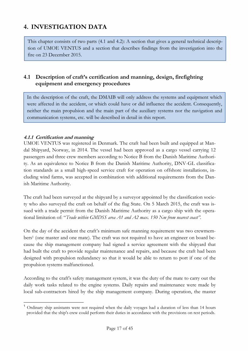
In the description of the craft, the DMAIB will only address the systems and equipment which
were affected in the accident, or which could have or did influence the accident. Consequently,
neither the main propulsion and the main part of the auxiliary systems nor the navigation and
communication systems, etc. will be described in detail in this report.
This chapter consists of two parts (4.1 and 4.2): A section that gives a general technical descrip-
tion of UMOE VENTUS and a section that describes findings from the investigation into the
fire on 23 December 2015.
INVESTIGATION DATA 4.
4.1 Description of craft’s certification and manning, design, firefighting equipment and emergency procedures
Certification and manning 4.1.1UMOE VENTUS was registered in Denmark. The craft had been built and equipped at Man-
dal Shipyard, Norway, in 2014. The vessel had been approved as a cargo vessel carrying 12
passengers and three crew members according to Notice B from the Danish Maritime Authori-
ty. As an equivalence to Notice B from the Danish Maritime Authority, DNV-GL classifica-
tion standards as a small high-speed service craft for operation on offshore installations, in-
cluding wind farms, was accepted in combination with additional requirements from the Dan-
ish Maritime Authority.
The craft had been surveyed at the shipyard by a surveyor appointed by the classification socie-
ty who also surveyed the craft on behalf of the flag State. On 5 March 2015, the craft was is-
sued with a trade permit from the Danish Maritime Authority as a cargo ship with the opera-
tional limitation of: “Trade within GMDSS area A1 and A2 max. 150 Nm from nearest coast”.
On the day of the accident the craft’s minimum safe manning requirement was two crewmem-
bers1 (one master and one mate). The craft was not required to have an engineer on board be-
cause the ship management company had signed a service agreement with the shipyard that
had built the craft to provide regular maintenance and repairs, and because the craft had been
designed with propulsion redundancy so that it would be able to return to port if one of the
propulsion systems malfunctioned.
According to the craft's safety management system, it was the duty of the mate to carry out the
daily work tasks related to the engine systems. Daily repairs and maintenance were made by
local sub-contractors hired by the ship management company. During operation, the master
1 Ordinary ship assistants were not required when the daily voyages had a duration of less than 14 hours
provided that the ship's crew could perform their duties in accordance with the provisions on rest periods.

Page 18 of 45
Figure 7: Extract from general arrangement Source: Valling Ship Management
Lift fan Vent valves
Draught reduction
was in charge of the navigation and the mate was in charge of monitoring the engine systems
on the engine control panels located on the bridge.
UMOE VENTUS had two crew cabins and was manned with three crewmembers, which
meant that one crewmember had to rest ashore. This put a time restriction of 14 hours per day
on the operation of the craft because one of the crewmembers had to disembark the craft to
get the mandatory rest hours. When the craft departed from the shipyard in Norway, it was
deemed possible to complete the voyage to the Kiel Canal in less than 14 hours, and the crew
would thereby comply with the rest hour regulations.
General description of UMOE VENTUS 4.1.2
UMOE VENTUS was designed as a service vessel for offshore wind farms, intended for carry-
ing technicians and small equipment items to wind turbines. The craft was a high-speed surface
effect ship, i.e. it had rigid side hulls like a catamaran structure with flexible rubber sealings aft
and forward. Centrifugal fans provided air pressure in the space between the hulls and thereby
provided lift to reduce the draught (figure 7). The pressure in the air cushion was regulated by
vent valves located aft of the lift fans.
The craft's hull and superstructure had been made as a carbon fibre reinforced plastic sandwich
construction. The design philosophy of UMOE VENTUS was a craft that could transfer per-
sonnel and/or equipment from the craft to offshore wind turbines in adverse wind and swell
conditions of up to Beaufort 5-6 (8-13.8 m/s) and 2.5 metre significant wave height, while at
the same time being able to reach high speed and low fuel consumption.

Page 19 of 45
Figure 8: Extract from general arrangement Source: Valling Ship Management
Lift fan engines Diesel engines for water jets
The craft was equipped with two independent diesel driven water jet propulsion systems and
two engines for the lift fans on the port and starboard side (figure 8). The power supply system
comprised two diesel-driven generators, one located in each engine room in the port and star-
board side.
The entire hull and superstructure on UMOE VENTUS had been constructed of a composite
material. This structure enabled the craft to have characteristics that a conventional steel con-
struction could not provide, e.g. in terms of weight. Composites are made from a variety of
materials that give the composite structure different properties in terms of strength and flam-
mability. Therefore, it is relevant to examine the general characteristics of composite materials.

Page 20 of 45
Figure 9: The sandwich configuration compared with an I-beam on the left
General aspects of composite materials 4.1.3
Introduction
In the last 30 years, fibre composite materials have seen a growing popularity in a wide spec-
trum of different industries. Areas of application have first of all been aircraft and spacecraft,
but with a decreasing fibre material price of the most commonly used fibre types, composite
materials have eventually been applied on a larger scale in ships, cars, trains, wind generator
blades, offshore installations, etc. Common to most of these weight critical applications is the
need for reducing the weight of the structure to increase the strength-to-weight and stiffness-
to-weight ratios and thus obtain better performance and/or an increased loading capacity, and
in many cases also reduce the maintenance costs. With regard to the strength- and stiffness-to-
weight ratios, composites and especially sandwich composites possess superior performance.
Other advantageous properties are thermal and acoustic insulation, fatigue, corrosion and easy
manufacturing of hydro- and aero-dynamically superior shapes.
Sandwich composites
In order to utilize the material properties of the individual composite materials to the best
structural advantage, a sandwich configuration consists of two stiff and thin layers (the faces)
separated by a soft and light material (the core) (figure 9). The three layers are in most cases
glued together, thus forming two glue layers in the sandwich. The material choice and location
of the different materials in the sandwich can be compared to an ordinary I-beam, which can
be regarded as optimized with regard to the cross-sectional geometry (figure 9).
The advantage of the sandwich compared to the I-beam is that the optimization can be ex-
panded to be used as panels (bulkheads), resulting in a highly optimized lightweight structure,
whereas the geometrical cross-sectional optimisation in the I-beam is limited to the beams.
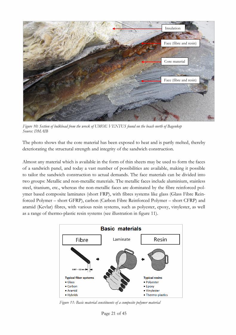
Figure 10 below is a photo of a bulkhead from the wreck of UMOE VENTUS. The photo
shows the sandwich construction with the face and core material. On the upper part of the
photo the remains of the fire resistant insulation can be seen.
Page 21 of 45
Figure 10: Section of bulkhead from the wreck of UMOE VENTUS found on the beach north of Bagenkop Source: DMAIB
Core material
Insulation
Face (fibre and resin)
Face (fibre and resin)
The photo shows that the core material has been exposed to heat and is partly melted, thereby
deteriorating the structural strength and integrity of the sandwich construction.
Almost any material which is available in the form of thin sheets may be used to form the faces
of a sandwich panel, and today a vast number of possibilities are available, making it possible
to tailor the sandwich construction to actual demands. The face materials can be divided into
two groups: Metallic and non-metallic materials. The metallic faces include aluminium, stainless
steel, titanium, etc., whereas the non-metallic faces are dominated by the fibre reinforced pol-
ymer based composite laminates (short FRP), with fibres systems like glass (Glass Fibre Rein-
forced Polymer – short GFRP), carbon (Carbon Fibre Reinforced Polymer – short CFRP) and
aramid (Kevlar) fibres, with various resin systems, such as polyester, epoxy, vinylester, as well
as a range of thermo-plastic resin systems (see illustration in figure 11).
Figure 11: Basic material constituents of a composite polymer material
Page 22 of 45
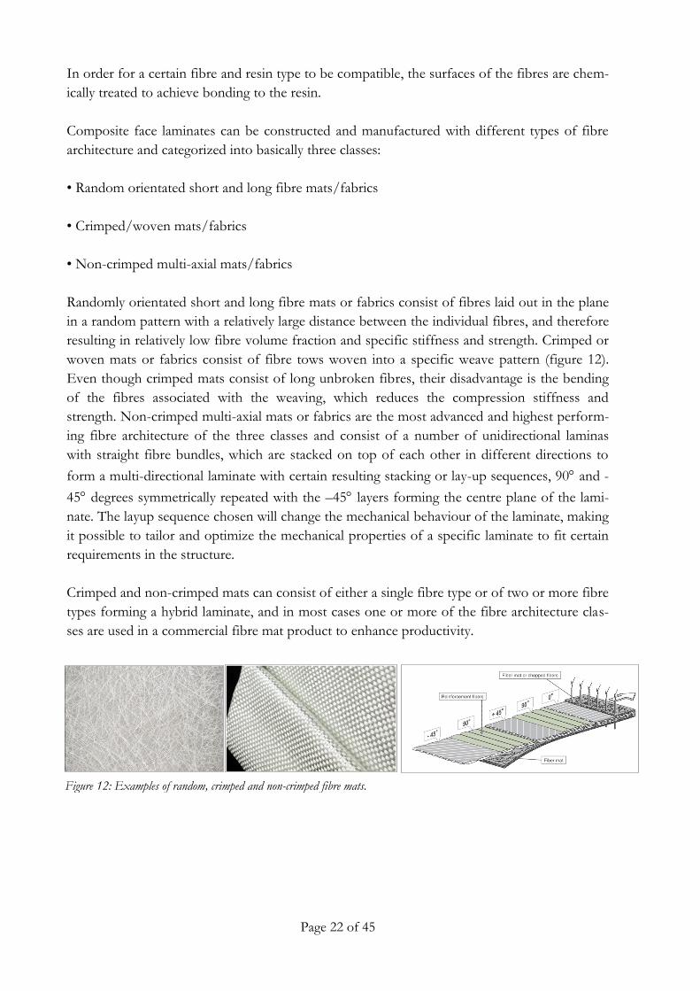
Figure 12: Examples of random, crimped and non-crimped fibre mats.
In order for a certain fibre and resin type to be compatible, the surfaces of the fibres are chem-
ically treated to achieve bonding to the resin.
Composite face laminates can be constructed and manufactured with different types of fibre
architecture and categorized into basically three classes:
• Random orientated short and long fibre mats/fabrics
• Crimped/woven mats/fabrics
• Non-crimped multi-axial mats/fabrics
Randomly orientated short and long fibre mats or fabrics consist of fibres laid out in the plane
in a random pattern with a relatively large distance between the individual fibres, and therefore
resulting in relatively low fibre volume fraction and specific stiffness and strength. Crimped or
woven mats or fabrics consist of fibre tows woven into a specific weave pattern (figure 12).
Even though crimped mats consist of long unbroken fibres, their disadvantage is the bending
of the fibres associated with the weaving, which reduces the compression stiffness and
strength. Non-crimped multi-axial mats or fabrics are the most advanced and highest perform-
ing fibre architecture of the three classes and consist of a number of unidirectional laminas
with straight fibre bundles, which are stacked on top of each other in different directions to
form a multi-directional laminate with certain resulting stacking or lay-up sequences, 90 and -
45 degrees symmetrically repeated with the –45 layers forming the centre plane of the lami-
nate. The layup sequence chosen will change the mechanical behaviour of the laminate, making
it possible to tailor and optimize the mechanical properties of a specific laminate to fit certain
requirements in the structure.
Crimped and non-crimped mats can consist of either a single fibre type or of two or more fibre
types forming a hybrid laminate, and in most cases one or more of the fibre architecture clas-
ses are used in a commercial fibre mat product to enhance productivity.

Page 23 of 45
Figure 13: Fibre mats from the wreck of UMOE VENTUS Source: DMAIB
The face sheets on UMOE VENTUS consisted of mostly multi-axial non-crimp mats in vari-ous layup sequences; similar to what is shown in figure 12 (right) and in figure 13 below.
The fibre types used on UMOE VENTUS were mainly of carbon and fibreglass. The polymer
resin/matrix types used in combination with the above-mentioned fibre mats for the manufac-
turing of the face sheets were of either the vinylester or polyester type depending on the loca-
tion of the bulkhead.
Other types of non-metallic face materials have generally also been used in sandwich compo-
sites, such as plywood, veneer and even cement. Common to all candidate materials is that the
primary demands on the face materials are:
• High stiffness giving high flexural rigidity • High tensile and compressive strength • Impact resistance • Surface finish • Environmental resistance (chemical, UV, heat, etc.) • Wear resistance

Page 24 of 45
Figure 14: Basic core material types
Figure 15: Core of bulwark from the wreck of UMOE VENTUS Source: DMAIB
In figure 14, the four main types of core materials are presented, the corrugated, the honey-
comb, the balsa and the cellular foam cores.
The corrugated cores are normally used in heavy industries such as large ships, but have how-
ever also found their way into the packaging industry. The honeycomb cores are to a great ex-
tent used in the aeronautical industry as they possess the highest performance compared to the
weight. The honeycomb cores are made of for example aluminium, aramid or resin impregnat-
ed paper, which is the cheapest version and seldom used for structural purposes. Honeycomb
is also produced in a large number of different geometries, but today the hexagonally (honey-
comb) shaped type (figure 14, middle) is the most popular. Unfortunately, structural honey-
combs are also very expensive and less tolerant of impact loads, which limits their application
to relatively protected structures. The balsa and especially the structural cellular foams possess
a good compromise between performance and price compared to the honeycomb cores. They
are more tolerant of localised loads acting on the sandwich component. Cellular foams are
therefore the favoured core type in maritime structures.
The sandwich composites used in UMOE VENTUS consisted of the foam cored type with a
range of different foam core densities and fibre reinforced polymer face sheet configurations at
different locations in the vessel, as shown in figure 14 (cellular or balsa) and as seen in the pic-
ture below (figure 15) from the wreck of UMOE VENTUS.

Page 25 of 45
There are several foam core types on the market, but the most popular is the structural polyvi-
nyl chloride (PVC) foam. PVC cores are available in a wide range of densities and material
properties and may be used in both a ductile (linear foam structure) and a more brittle version
(cross-linked foam structure). However, the linear ductile version is slowly being replaced by
the styrene acrylonitrile (SAN) foam core type, which is more tolerant of high temperatures
and in general a better performing material for structural use compared to the linear PVC
foam. Other core materials are the cheap polyurethane (PUR), which can be blown in between
the faces in a liquid form to subsequently densify, the polystyrene (PS), the polyisocyanurate
(PIR), the polyether imide (PEI) and the polymethacryl imide (PMI), which is more expensive
compared to the PVC core type and enjoys increased popularity in the aeronautical industry as
an alternative to the honeycomb core types. The most important demands on the core materi-
als are:
• Low density • Sufficient stiffness to prevent decrease in thickness under lateral loading (a limited decrease in
thickness leads to rapid decrease in flexural rigidity)
• Sufficient shear stiffness to ensure unwanted out-of-plane shear deformations • Sufficient stiffness to prevent local buckling of the faces (wrinkling) • Sufficient shear strength to prevent global core shear failure under lateral loading • Sufficient thermal insulation
Application of sandwich composites in the maritime industry
In the maritime industry, composite materials and sandwich structures have been utilized since
the middle of the last century. In the beginning mainly in smaller vessels like pleasure boats,
but also in more high-performance applications, like power boats. The step towards larger
composite vessels was taken by the military, just as in the aeronautical industry. Civilian appli-
cations of large composite and sandwich vessels have mostly been oriented towards high per-
forming, competition, oceangoing sailing boats, yachts, smaller ferries and special operations
vessels, such as offshore wind turbine inspection vessels, built by a number of Scandinavian
shipyards primarily in Denmark and Norway. An example of the latter special operations ves-
sels is UMOE VENTUS.
From the above it can be concluded that the diversity and continuous development of compo-
site materials makes it difficult to generalize about the structural properties of a ship built in these materials,
and how robust the ship will be towards adverse events such as fires and collisions. If the vari-
ous bulkheads are constructed in a composite material that is combustible, then robustness
towards fire must be obtained by the use of added structural and functional fire protection
initiatives.

Page 26 of 45
Figure 16: Extract from fire and safety plan UMOE VENTUS Source: DMAIB and Valling Ship Management
Forward Aft
Structural and functional fire protection on UMOE VENTUS 4.1.4
Several compartments in the craft were fitted with structural fire protection, i.e. some of the bulk-
heads and decks were insulated to ensure that energy (heat) from the fire could be contained for a
certain period of time. The lift fan engine compartment was insulated to an A302 standard and the
propulsion engine compartment was insulated to an A60 standard, as it can be seen on the below
extract from the craft’s fire and safety plan (figure 16). The semi-open lift fan compartment was
not fitted with any structural fire protection.
UMOE VENTUS was equipped with three functionally different fixed fire protection systems:
A sprinkler system, a foam system and a NOVEC 1230 (a third generation substitute for Hal-
on). The sprinkler system covered the accommodation areas, including the passenger lounge,
pantry, stairway and hallway. All of the accommodation bulkheads had been built using a carbon
fibre reinforced plastic sandwich construction and therefore relied on the functional fire protec-
tion to provide protection equivalent to an A-0 division (uninsulated steel construction).
Functional fire protection (e.g. sprinklers) is based on certain conditions being fulfilled, e.g.
proper maintenance, due activation and that it is being used for the designed purpose, which
brings a complexity to the shipboard system that passive protection, such as insulated bulk-
heads or steel bulkheads, does not have (see the analysis section for further elaboration on the
subject of using functional fire protection systems). The foam and gas systems covered the
2 'A' class divisions are bulkheads and decks constructed of steel or other equivalent material, capable of preventing the
passage of smoke and flame to the end of the one-hour standard fire test. They are insulated with approved materials such that the average temperature of the unexposed side will not rise more than 139°C above the original tempera-ture, nor will the temperature at any one point, including any joint, rise more than 180°C above the original tempera-ture, within the time: A-60 (60 minutes), A-30 (30 minutes), A-15 (15 minutes) and A-0 (0 minutes).
Page 27 of 45
propulsion engine rooms on the port and starboard side, and the lift fan engine room on the
port and starboard side. The sprinkler system could be operated from the exit door on the
bridge and from the port and starboard side exit doors on the main deck. The foam system
could be activated from the bridge and from control panels located in the starboard and port
generator rooms. The gas system could be released from a control station located in front of
the accommodation on the main deck.
Fires on the deck area were meant to be extinguished using the two fire hydrants on deck and
two fire hoses mounted in two cabinets on deck. One firefighter outfit including breathing
apparatus was located on the bridge. Additionally the craft was equipped with 18 portable ex-
tinguishers located in various places on the craft. On the day of the fire the crewmembers used
none of the firefighting equipment.
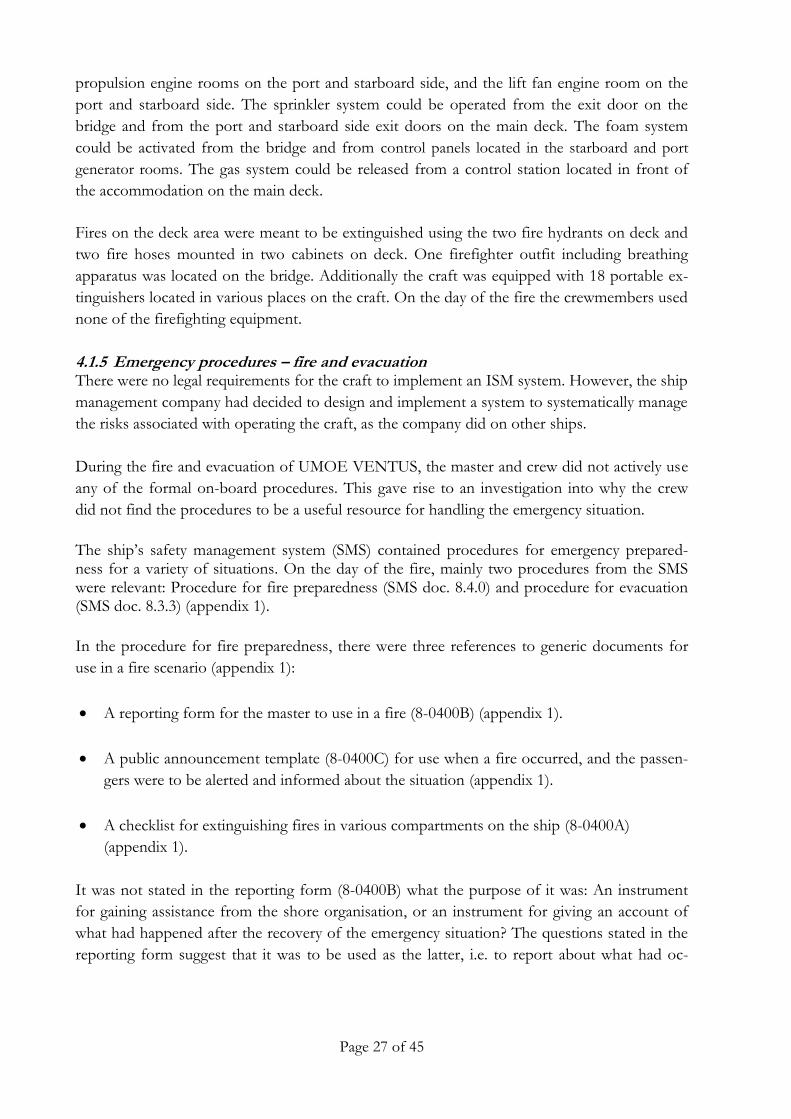
Emergency procedures – fire and evacuation 4.1.5There were no legal requirements for the craft to implement an ISM system. However, the ship
management company had decided to design and implement a system to systematically manage
the risks associated with operating the craft, as the company did on other ships.
During the fire and evacuation of UMOE VENTUS, the master and crew did not actively use
any of the formal on-board procedures. This gave rise to an investigation into why the crew
did not find the procedures to be a useful resource for handling the emergency situation.
The ship’s safety management system (SMS) contained procedures for emergency prepared-ness for a variety of situations. On the day of the fire, mainly two procedures from the SMS were relevant: Procedure for fire preparedness (SMS doc. 8.4.0) and procedure for evacuation (SMS doc. 8.3.3) (appendix 1).
In the procedure for fire preparedness, there were three references to generic documents for
use in a fire scenario (appendix 1):
A reporting form for the master to use in a fire (8-0400B) (appendix 1).
A public announcement template (8-0400C) for use when a fire occurred, and the passen-
gers were to be alerted and informed about the situation (appendix 1).
A checklist for extinguishing fires in various compartments on the ship (8-0400A)
(appendix 1).
It was not stated in the reporting form (8-0400B) what the purpose of it was: An instrument
for gaining assistance from the shore organisation, or an instrument for giving an account of
what had happened after the recovery of the emergency situation? The questions stated in the
reporting form suggest that it was to be used as the latter, i.e. to report about what had oc-
Page 28 of 45
curred on the ship. Due to the necessity of a speedy evacuation and facing a total loss of the
ship, the recovery situation was not reached. Hence, the reporting was not relevant to the crew.
The public announcement template (8-0400C) was to be used by the master or another crew-
member on the bridge to inform the passengers about an ongoing fire. From the template it
can be seen that it was intended to be used in two circumstances: When the passengers were
not aware of a fire, or when the passengers were aware of a fire. The announcement template
seems to have been designed for a larger ship where the passengers would only have
knowledge about events in their immediate vicinity. The size of UMOE VENTUS meant that
the procedure would have little effect because the passengers would immediately be aware in
case of a fire. On 23 December, there was only one passenger on board (the shipyard warranty
engineer) and he was involved in the events to an extent that the use of the template was su-
perfluous.
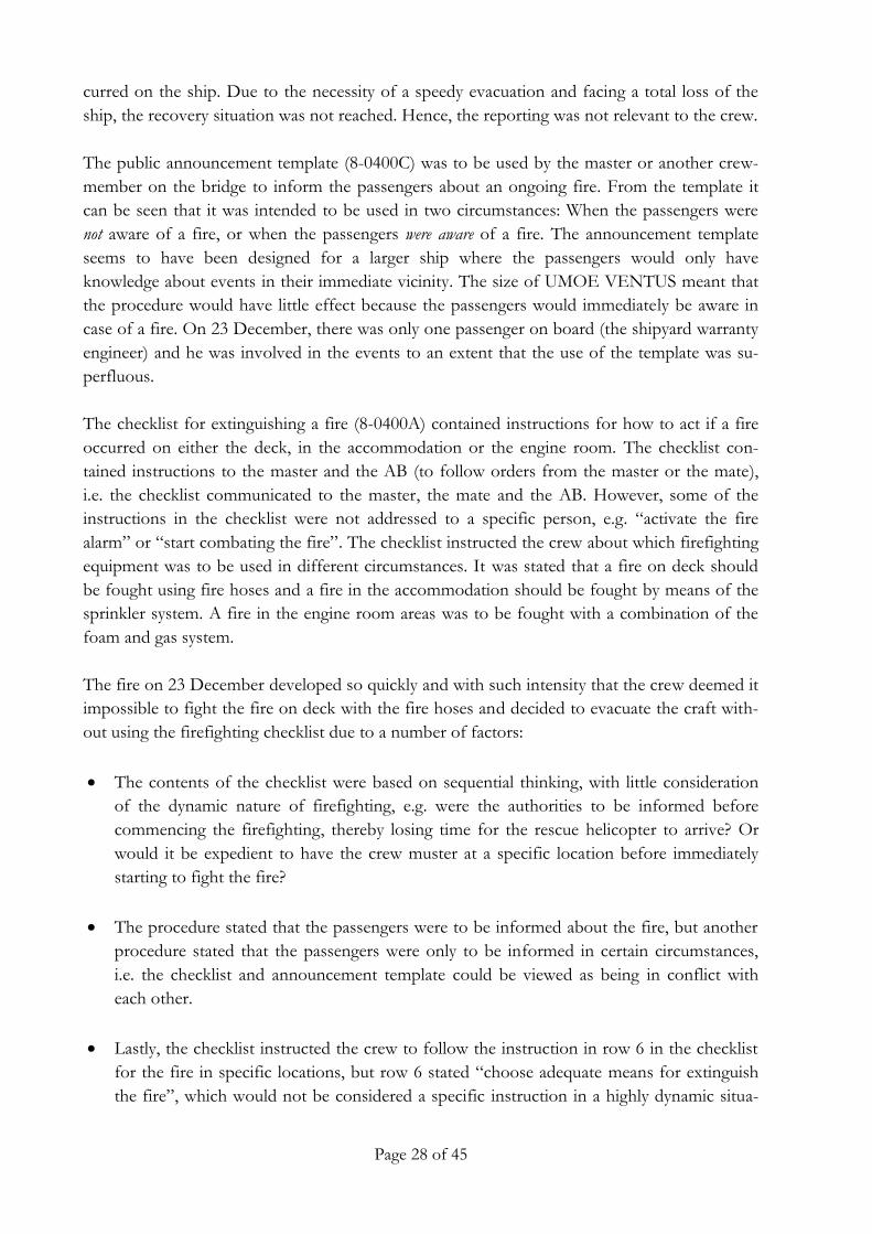
The checklist for extinguishing a fire (8-0400A) contained instructions for how to act if a fire
occurred on either the deck, in the accommodation or the engine room. The checklist con-
tained instructions to the master and the AB (to follow orders from the master or the mate),
i.e. the checklist communicated to the master, the mate and the AB. However, some of the
instructions in the checklist were not addressed to a specific person, e.g. “activate the fire
alarm” or “start combating the fire”. The checklist instructed the crew about which firefighting
equipment was to be used in different circumstances. It was stated that a fire on deck should
be fought using fire hoses and a fire in the accommodation should be fought by means of the
sprinkler system. A fire in the engine room areas was to be fought with a combination of the
foam and gas system.
The fire on 23 December developed so quickly and with such intensity that the crew deemed it
impossible to fight the fire on deck with the fire hoses and decided to evacuate the craft with-
out using the firefighting checklist due to a number of factors:
The contents of the checklist were based on sequential thinking, with little consideration
of the dynamic nature of firefighting, e.g. were the authorities to be informed before
commencing the firefighting, thereby losing time for the rescue helicopter to arrive? Or
would it be expedient to have the crew muster at a specific location before immediately
starting to fight the fire?
The procedure stated that the passengers were to be informed about the fire, but another
procedure stated that the passengers were only to be informed in certain circumstances,
i.e. the checklist and announcement template could be viewed as being in conflict with
each other.
Lastly, the checklist instructed the crew to follow the instruction in row 6 in the checklist
for the fire in specific locations, but row 6 stated “choose adequate means for extinguish
the fire”, which would not be considered a specific instruction in a highly dynamic situa-
Page 29 of 45
In this section the following topics will be addressed separately: The time of the fire, the origin
of the fire, the probable cause of the fire and the spread of the fire.
tion. Row 7 of the checklist contained references to specific equipment and stated “pre-
pare the fire hoses” followed by “start combating the fire”, which was a very specific in-
struction followed by a broad instruction to do something that involved many considera-
tions and individual choices.
The evacuation procedure of the craft did not have a reference to a checklist, but referred to a
procedure about shore-based crisis preparedness and an additional reference to SOLAS3 chap-
ter III (Life-saving appliances and arrangements). The evacuation procedure contained various
action points for the master to address in an evacuation situation and described that it was to
be done in cooperation with the shore-based crisis staff. The procedure contained instructions
about the state of mind of the master and/or crew, e.g. “stay calm” or “act masterfully”, but
the procedure also referred to specific tasks, e.g. “neutralize panicky behaviour” or “activate
the evacuation alarm”. Invoking a certain state of mind in an emergency situation is not likely
to be effective in a situation that calls for specific advice or instruction. During the evacuation
the crew were preoccupied with evaluating the right time to leave the ship, which was not ad-
dressed in any detail in the evacuation procedure, and they were preoccupied with evaluating
the possibility of evacuating the ship via the approaching fishing vessel, which was considered
safer than using the life raft as prescribed in the procedure. The problems gaining a safe dis-
tance between the burning craft and the life raft were not addressed in the procedure.
The fire developed and spread so quickly that it was difficult to stay on the bridge where the
SMS was located and left little or no time to read through the material and fill out the forms.
Furthermore, the emergency situation was not manageable with the strategies described in the
SMS due to a number of factors that were related overall to the dynamic nature of the situation
for which the SMS was not designed. Furthermore, the fire was so intense and developed so
rapidly that it was not considered possible to fight the fire with the fire hoses or use any of the
strategies prescribed in the various SMS documents. This indicates that the SMS was designed
for a type and size of craft other than UMOE VENTUS and/or for situations different from
the one UMOE VENTUS’ crew faced on the day of the accident. The usability of the proce-
dures will be further analysed in the analysis section.
4.2 The time, origin, cause and spread of the fire
The time of the fire 4.2.1The time of the discovery of the fire could be established on the basis of the witness state-ments, the master’s distress call, the on board alarm/event logs and the craft’s AIS data. The quality of the retrieved AIS data has been deemed to be valid because the AIS transmissions
3 The International Convention for the Safety of Life at Sea.

Page 30 of 45
were found to be consistent over several days. The data have been considered credible because they are concordant with other collected data.
There were no fire detection alarms prior to the crewmember’s discovery of the fire. The initial
smoke and fire was observed by the different crewmembers on the bridge and the deck area
within a narrow time span. The master was positioned at the port side conning station and was
in the process of turning the ship and increasing the speed when he saw the smoke and flames.
From the AIS it can be seen that at 1234 the craft increased its speed and initiated a port turn
and changed heading from an easterly course to a southerly course after which the craft came
to an almost complete stop a minute later. The distress call was received by coastal radio sta-
tion Lyngby Radio at 1236. The discovery of the fire was therefore at approximately 1235.
The exact time when the fire broke out is, however, uncertain because the fire could have de-
veloped for some time prior to the crew noticing the fire. If the fire started in the lift fan com-
partment while the fan was in operation, the fan would direct the flames and smoke into the air
cushion while cooling the area, thereby limiting the out-board spread of the fire. The lift fan
engine was, according to the event log, turned off at 1223. Only when the master turned off
the lift fan motor, would the flames be directed outwards from the hull and become visible
from the port side bridge window. The rapid development and intensity of the fire suggests
that the fire had been developing for a period of time prior to its discovery. The mate inspect-
ed the main engine rooms at 1220 according to the event log showing that the water tight door
was opened for the last time. After this inspection the mate reported smell of overheating. This
was about 15 minutes before flames were observed. It is a possibility that the fire was develop-
ing at this time without being noticed.
The origin of the fire 4.2.2In the crew’s recollection of the events, the fire was initially seen coming from the port side lift
fan compartment. There was no warning about the fire from the craft’s automatic fire detec-
tion system, which was not activated (from the passenger lounge) until the fire had spread to
the bulwark. The extract from the fire and safety plan in figure 14 shows that the lift fan was
adjacent to the main engine room and the lift fan engine room. The main engine room and the
lift fan engine room were protected structurally by an A60 bulkhead and an A30 bulkhead,
respectively.
It is unlikely that the fire started within one of the adjacent engine compartments and burned
for a prolonged period, while all the fire detectors in the rooms malfunctioned, and broke out
through the bulkhead without the crew noticing. It is, however, more likely that the fire origi-
nated from the lift fan compartment itself, which was not equipped with a fire detection sys-
tem.
In figure 17 below is a photo of the starboard side lift fan compartment, which was similar to
the port side compartment. Inside the compartment there were four components: the lift fan

Page 31 of 45
Figure 17: Picture of starboard side lifting fan compartment on UMOE VENTUS Source: Private photo
Exhaust gas from lifting fan engine
Drive shaft to fan
Lift fan housing
Exhaust muffler
housing, the exhaust pipe from the lift fan engine, the exhaust muffler and the drive shaft to
the fan.
There were indications that the fire originated from the exhaust gas system because there were
several alarms on the cooling water system while the craft was arriving in Bagenkop and upon
departure from Bagenkop.
Therefore, there is a likely correlation between the loss of cooling water pressure, the high
temperature on the lift fan engine, as experienced by the crew, and the lift fan engine exhaust
muffler which was cooled by the central cooling water system.
The probable cause of the fire 4.2.3
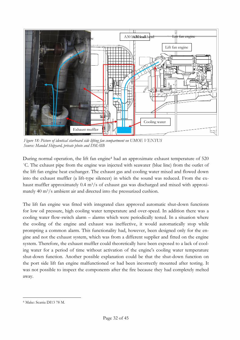
Figure 18 below shows the layout of the lift fan engine exhaust system. On the right hand side
of the layout is the engine, in the centre an A30 bulkhead and on the left is a picture of the
exhaust pipe and the exhaust muffler.
Page 32 of 45
Lift fan engine A30 bulkhead Exhaust pipe
Figure 18: Picture of identical starboard side lifting fan compartment on UMOE VENTUS Source: Mandal Shipyard, private photo and DMAIB
Cooling water
Lift fan engine
Exhaust muffler
A30 bulkhead
During normal operation, the lift fan engine4 had an approximate exhaust temperature of 520
˚C. The exhaust pipe from the engine was injected with seawater (blue line) from the outlet of
the lift fan engine heat exchanger. The exhaust gas and cooling water mixed and flowed down
into the exhaust muffler (a lift-type silencer) in which the sound was reduced. From the ex-
haust muffler approximately 0.4 m3/s of exhaust gas was discharged and mixed with approxi-
mately 40 m3/s ambient air and directed into the pressurized cushion.
The lift fan engine was fitted with integrated class approved automatic shut-down functions
for low oil pressure, high cooling water temperature and over-speed. In addition there was a
cooling water flow-switch alarm – alarms which were periodically tested. In a situation where
the cooling of the engine and exhaust was ineffective, it would automatically stop while
prompting a common alarm. This functionality had, however, been designed only for the en-
gine and not the exhaust system, which was from a different supplier and fitted on the engine
system. Therefore, the exhaust muffler could theoretically have been exposed to a lack of cool-
ing water for a period of time without activation of the engine's cooling water temperature
shut-down function. Another possible explanation could be that the shut-down function on
the port side lift fan engine malfunctioned or had been incorrectly mounted after testing. It
was not possible to inspect the components after the fire because they had completely melted
away.
4 Make: Scania DI13 78 M.

Page 33 of 45
In appendix 2 is an overview of trend data retrieved from UMOE VENTUS’s platform man-
agement server. The trend data cover the day of arrival on 22 December and the day of depar-
ture from Bagenkop on 23 December. On the horizontal axis time (UTC) is depicted and on
the vertical axis various system values are depicted. The system values shown are the main en-
gine RPM, the seawater cooling pressure and the lift fan bearing temperature.
It can be seen that during arrival on 22 December at 1435 (UTC), the seawater cooling water
pressure at times decreased to below 1 bar which coincides with various system alarms, includ-
ing the cooling water alarms the crew got while approaching Bagenkop – alarms that were not
reacted upon because the crew believed that the craft was about to sink (see section 3.2.1).
During departure from Bagenkop on 23 December, several common alarms on the port side
lifting fan engine were activated due to the continuous low seawater cooling pressure. The port
side lifting fan engine was stopped at 1123 (UTC) whereafter the master tried to back-flush the
seawater filters (testing high suction). Thereafter, at 1133 (UTC), it can be seen that the bearing
temperature on the port side lift fan engine was increasing indicating that a fire in the port side
lift fan compartment had started.
It has not been possible to determine with certainty what caused the drop in pressure on the
seawater cooling system because the fire caused extensive damage to the ship structure and
equipment that was spread out on the seabed. The condition of the valves and strainers could
not give reliable information about the state of the system at the time of the accident. An in-
vestigation of the main seawater pumps did not indicate any significant wear or malfunction
that would cause a significant drop in the seawater pressure on the main cooling water system.
The warranty engineer inspected the seawater cooling system filter before departure from Ba-
genkop, but the filters were inspected and found to be clean. The sea chest strainers were not
checked because it was deemed unlikely that they were clogged (the mesh size was large 8
mm). It is, however, likely that the sea chest was clogged by plastic or other material which had
been sucked up into the sea chest strainer during arrival in Bagenkop, because the drop of
pressure affected the entire port side cooling water system. The master’s attempt to flush the
sea intake would not have cleaned the strainer, because the flushing function was designed to
clear open the main intake and not the strainer.
The port side lift fan engine cooling water impeller pump would not be able to run for a pro-
longed period without a water flow before malfunctioning – causing insufficient cooling of the
lift fan engine and the exhaust. An investigation into the starboard side lift fan engine showed
that it did not experience a loss of cooling water as the exhaust muffler was found to be intact
(figure 19).

Page 34 of 45
Figure 19: Picture of starboard side exhaust muffler found on the salvaged wreck Source: DMAIB
The loss of pressure on the main cooling water system would not necessarily result in an even-
ly distributed loss of flow of cooling water in all the port side engines because the port side
main engine was equipped with a larger centrifugal cooling water pump, which would create
larger suction than the smaller impeller pump on the port side lift fan engine.
The lift fan engine exhaust muffler had been made by a sub-supplier and been approved by
Lloyd’s Register to a maximum operating temperature of 85˚C. If the flow of cooling water
was disrupted, the exhaust muffler would be directly exposed to the exhaust gas from the en-
gine at an approximate temperature of 520 ˚C. This could ignite the muffler and/or the deck
and/or bulkhead where it was mounted. The hose connecting the exhaust piping from the en-
gine with the exhaust muffler had been designed for use at temperatures of up to 180 ˚C and
could therefore also be ignited by the exhaust gases.
It was unclear at which temperatures the bulkhead would ignite because the bulkhead’s fire
resistance had only been tested to be in compliance with the relevant IMO resolutions,5 which
means that the tests were based on bulkheads with insulation. It was therefore unclear whether
the composite bulkheads could be ignited directly from the exhaust gas or if another fire was
necessary to facilitate the necessary temperatures for the bulkhead to ignite, e.g. a fire in the
exhaust muffler.
In order to establish the ignition temperature of the bulkhead in the lift fan compartments, the
DMAIB requested the Danish Institute of Fire and Security Technology (DBI) to conduct a
test of the ignition properties of bulkhead samples from the lift fan compartment and super-
5 IMO Resolution MSC.307(88) – (FTP Code 2010) and IMO Resolution MSC.61(67) – (FTP Code).
Page 35 of 45
structure of UMOE VENTUS (appendix 3). Both painted bulkheads and bulkheads without
paint were tested.
The following is an extract from the test report:
“The conclusion on ignition temperature is that the painted panel can ignite in the smoke gas tem-
perature range of approx. 275-315 °C and the untreated panel in the range of approx. 330-370
°C”.
“Ignition temperature” is a non-fundamental parameter that should be used with care. Ignition oc-
curs when the right smoke gas temperature and the right smoke gas/oxygen ratio are present –
this is never the same in each test. Is either “correct” temperature or “correct” smoke gas/oxygen
ratio missing - no ignition occurs. Furthermore temperature is device dependent measurement”.
“These test results relate only to the behaviour of the product under the particular conditions of the
test, and they are not intended to be the sole criterion for assessing the potential fire hazard of the
product in use”.
The test indicates that the exhaust gas temperature (520°C) from the lift fan engine had the
potential to ignite the bulkheads in the lift fan compartment. This means that the heat radiation
from an overheating exhaust muffler and/or the connected hoses could have started the fire in
the lifting fan compartment.
The spread of the fire 4.2.4Due to the extensive damage to the salvaged wreck, it was not possible to establish with cer-
tainty how the fire had spread in the early stages of the fire. Therefore, it was difficult to estab-
lish the duration of the fire prior to the crew’s discovering it. The development of the fire in its
later stages can mainly be established from aerial photos and witness accounts.
Within a few minutes after the discovery of the fire, it spread to the bulwark and the port side
of the accommodation. Within 10 minutes there were visible flames inside the passenger
lounge. After approximately 15 minutes and shortly after the crew had evacuated the craft, the
entire accommodation was engulfed in flames.

Page 36 of 45
Figure 20: Picture of UMOE VENTUS seen from above Source: TV2/Danmark A/S
Figure 21: Picture of UMOE VENTUS seen from aft Source: TV2/Danmark A/S
Figures 20 and 21 are aerial photos after UMOE VENTUS had grounded – approximately 3
hours after the fire was discovered by the crew.
From both photos it can be seen that the starboard side outer hull was almost intact. The en-
tire accommodation was destroyed and the centre deck structure between the two hulls had
collapsed inwards.
Page 37 of 45
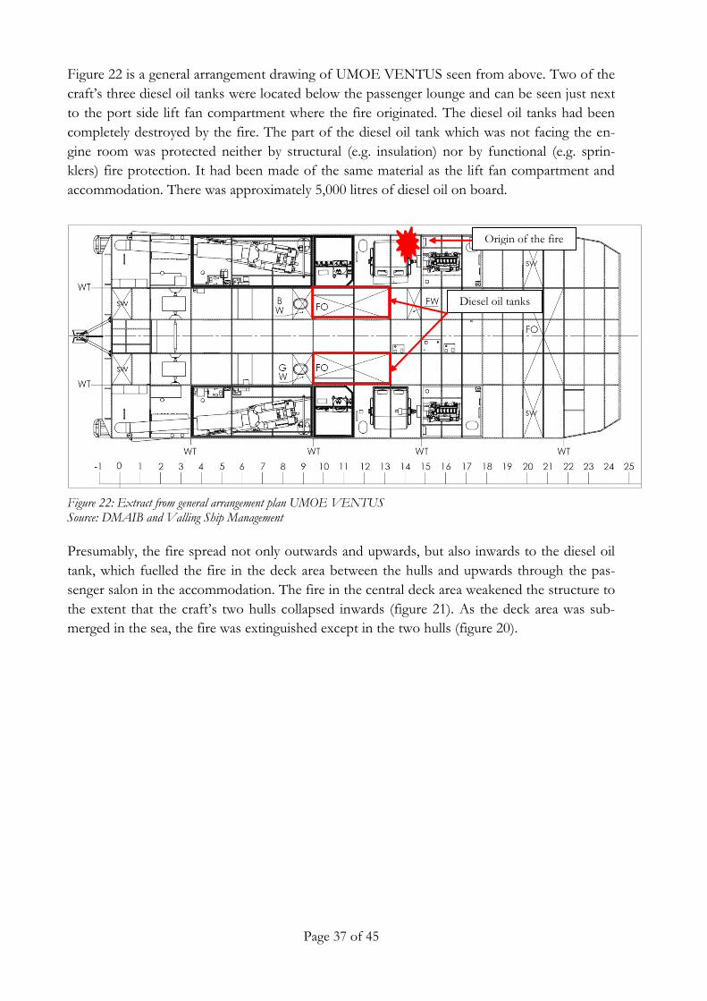
Figure 22: Extract from general arrangement plan UMOE VENTUS Source: DMAIB and Valling Ship Management
Diesel oil tanks
Origin of the fire
Figure 22 is a general arrangement drawing of UMOE VENTUS seen from above. Two of the
craft’s three diesel oil tanks were located below the passenger lounge and can be seen just next
to the port side lift fan compartment where the fire originated. The diesel oil tanks had been
completely destroyed by the fire. The part of the diesel oil tank which was not facing the en-
gine room was protected neither by structural (e.g. insulation) nor by functional (e.g. sprin-
klers) fire protection. It had been made of the same material as the lift fan compartment and
accommodation. There was approximately 5,000 litres of diesel oil on board.
Presumably, the fire spread not only outwards and upwards, but also inwards to the diesel oil
tank, which fuelled the fire in the deck area between the hulls and upwards through the pas-
senger salon in the accommodation. The fire in the central deck area weakened the structure to
the extent that the craft’s two hulls collapsed inwards (figure 21). As the deck area was sub-
merged in the sea, the fire was extinguished except in the two hulls (figure 20).

Page 38 of 45
ANALYSIS 5.
The overall aim of the investigation was to establish why a mechanical malfunction of the cool-
ing water system led to an uncontrollable fire that engulfed most of UMOE VENTUS within
approximately 15 minutes after the fire was visually detected and resulted in a total loss of the
craft. The focus of the investigation was UMOE VENTUS’ robustness towards fire.
5.1 The cause of the fire
The investigation has found that the cause of the fire on UMOE VENTUS was insufficient
cooling of the lift fan engine exhaust system, which ignited the exhaust muffler (including con-
nected hoses) and/or the bulkheads where the exhaust muffler was mounted on the port side
lift fan compartment. Due to the extensive damage to the craft, it has not been possible to es-
tablish with certainty why the seawater cooling system lost pressure resulting in insufficient
cooling of the lift fan engine exhaust. A likely scenario was that the sea chest strainer was
clogged resulting in an insufficient flow of water to the central cooling water system on the
port side. The cooling water pumps on the port side main engine managed to create sufficient
suction to supply the port side main engine with cooling water, but at the same time also de-
prived the port side lift fan engine of a sufficient flow of seawater. The lack of cooling water
flow to the port side lift fan engine cooling water impeller pump caused it to malfunction and
completely stopped the flow of cooling water to the lift fan engine. The automatic shut-down
function on the port side lift fan engine malfunctioned, causing it to run while overheating and
without providing cooling of the exhaust system.
During arrival and departure at the last port, Bagenkop, there were several system alarms on
the cooling water system indicating that the system did not function properly. The crew’s and
warranty engineer’s fault-finding efforts did not provide any clarity as regards the source of the
alarms. The crew and the manager of the craft chose to continue the voyage from Bagenkop.
The decision to continue the voyage and not promptly respond to the alarms on the cooling
water system should be seen in the context of the events from the preceding days, which will
be described in the following section.
5.2 The operation and management of the craft
During the voyage from the shipyard in Mandal, Norway, to Bagenkop, the crewmembers had
experienced numerous technical problems and alarms that gave the crewmembers the impres-
sion that the craft was in an unstable condition. However, the master did not consider the craft
unseaworthy – mainly for two reasons:
Firstly, the master relied on the warranty engineer to assess and initiate repairs of the malfunc-
tions because he had the technical insight to make decisions in technical matters because he
was perceived to be a representative of the technical management. A perception that was en-
hanced by the warranty engineers willingness to participate in fault finding and repairs. Fur-
Page 39 of 45
thermore, the craft was continuously being repaired and there was confidence that the craft
would eventually become mechanically reliable.
Secondly, there was a deadline for bringing the craft into service that had an impact on the
decision to push the limits for when the craft was considered to be fully operational. That limit
was reached when the ship arrived in Bagenkop and the management acknowledged that it was
not possible to make the craft available for the charterer within the deadline.
These mechanical problems influenced the reaction of the crew in relation to the malfunctions
that occurred shortly after departure from Bagenkop. The alarms for cooling water low pres-
sure and high temperature on the lift fan engine were not considered to be an extraordinary
event because the master’s and mate’s mind-set and sensitivity towards alarms had been altered
during the events of the last four days. When the cooling water system malfunctioned, several
alarms on the cooling water system and lifting fan engine indicated that there was a technical
problem. The crew did not consider these alarms to be safety critical. Since the craft had left
the shipyard, the crew had been exposed to an abundance of true and false engine system
alarms and several technical breakdowns which made the crew consider the craft as being in a
permanently unstable condition. During arrival in Bagenkop, the focus of the crew was on
bringing the craft safely alongside and not on the failing cooling water system. It was never
considered an option that the malfunctioning cooling water system would or could cause a fire.
Considering the events in the days prior to the fire, the craft was not in a stable and seaworthy
condition. The national6 regulation assigns responsibility to the master regarding establishing
the seaworthiness of the craft, but that responsibility was not necessarily matched by the mas-
ter’s power to act. The master worked in an environment of distributed authority – between
the charterer, the ship management organisation, and the owners. In the continuous communi-
cation with the shore-based technical and commercial management, the master was subjected
to other forms of authority that challenged his perception of his own authority on board the
craft. Thereby, this accident highlights how the position of the master can be challenged in
relation to the management of the craft.
5.3 UMOE VENTUS’ robustness towards fire
UMOE VENTUS’s robustness towards the spread of a fire consisted of the structural fire pro-
tection (bulkheads, insulation, etc.), the functional fire protection (various types of equipment,
e.g. portable fire extinguishers) and the crewmembers’ operational capacity to fight the fire by
using the on-board procedures. These fire protection initiatives were based on the standards
set by the classification society and the Danish flag State regulation. Additional equipment to
the craft’s fire suppression capabilities was installed at the owner’s initiative, i.e. having several
different systems; a sprinkler system, a foam system and a gas system as fixed firefighting sys-
tems for the various compartments or having fire fighter equipment.
6 The merchant shipping act no. 75 of 17 January 2014, chapter 6, section 131.

Page 40 of 45
All of the fire protection systems were based on the premise of the occurrence of certain fire
scenarios, e.g. engine room fires or fires inside the accommodation were potential sources of
fire that could be identified. It will be addressed in the following why these fire protection ini-
tiatives were inadequate to contain and control the fire scenario that occurred on 23 December
2015.
Structural and functional fire protection 5.3.1
Neither the manufacturer nor the authorities considered the lift fan compartments to be ex-
posed to a high risk of fire. Therefore, there was no regulatory or design requirement for the
lift fan compartments to be either constructed with insulated bulkheads for fire protection or
equipped with fire detectors and a fixed firefighting system. The ignition of the fire could hap-
pen unnoticed by the crew and could rapidly develop and spread from the port side lift fan
compartment because the open lift fan compartment provided large volumes of air to the fire,
and the surrounding bulkheads added combustible material to the fire. Subsequently, the fire
spread unhindered from the lift fan compartment upwards to the deck area and accommoda-
tion, and inwards to the diesel oil tank.
The fixed firefighting equipment (sprinkler, gas and foam installations) was designed to func-
tion within selected enclosed spaces (engine rooms and accommodation) and would therefore
not be effective in a fire scenario where the fire originated from the lift fan compartment and
spread to the open deck outside of the accommodation.
Once the fire had spread to the bulwark and the outside of the accommodation, the only op-
tion for the crewmembers was to utilize the fire hoses and portable extinguishers. After the
discovery of the fire, the crewmembers had little time to evaluate the situation because the fire
quickly became so intense that their immediate focus was on evacuating the craft because it
was apparent for them that it would be futile to start extinguishing the fire with the equipment
designed for a fire on deck. Furthermore, the smoke from the fire was perceived to be highly
toxic, which hindered free movement on the deck and influenced the decision to immediately
evacuate the craft without attempting to extinguish the fire.
The rapid development of the fire was made possible by the uninsulated carbon fibre rein-
forced plastic sandwich construction bulkheads that fuelled the fire and enabled it to spread
uncontrollably, which resulted in the structural collapse of the deck between the hulls. The use
of uninsulated carbon fibre reinforced plastic sandwich construction bulkheads will be elabo-
rated in the following.
Carbon fibre reinforced plastic sandwich bulkheads
UMOE VENTUS had been built with the basic design philosophy of a craft that could trans-
fer personnel and/or goods to offshore wind turbines in higher sea states than other similar
craft, while at the same time being an energy effective platform with very high speed and low
fuel consumption. The craft had been designed to have a distinct design profile as regards its
form, function, operative performance, choice of materials and components. To achieve these

Page 41 of 45
structural and operational goals, the craft had, inter alia, been constructed with carbon fibre
reinforced plastic sandwich bulkheads.
As described in section 4.1.3, a general key aspect in the design of composite structures is the
ability to take advantage of the building material and utilize it to its operational limits. That
operational limit is dependent on the choice of material and manufacturing method. On
UMOE VENTUS the composites were sensitive to heat in relation to the structural integrity
of the deck and bulkhead and sensitive to a rapid development of fire because the composite
materials were combustible.
These characteristics of the composites led to requirements for equivalent solutions to meet
the protective characteristics that class A and B bulkheads provide according to the require-
ments in the national regulation7, which were based on constructing bulkheads of steel or other
equivalent material.
UMOE VENTUS had been constructed on the basis of DNV-GL classification standards for
small high-speed service craft for operation on offshore installations with additional require-
ments from the Danish Maritime Authority regarding, inter alia, the structural fire protection
inside the engine rooms. These standards required the engine room to be fitted with structural
fire protection only inside the compartment where it was imagined that the fire could originate.
One characteristic of having a fire-resistant bulkhead, such as steel, is that it offers a passive
structural protection with little sensitivity to variation in emergency scenarios, i.e. various types
of fire scenarios not previously imagined in the design process. Furthermore, it can structurally
contain fire for a long period, which provides time for the crew and passengers to evacuate the
craft without depending on the active use of extinguishing equipment. The purpose of a func-
tional fire protection system is to extinguish or contain fire based on conditional use. This means
that the functioning of the system is dependent on the mechanical reliability of the system and
that it is operationally applied in a correct manner at the correct time. With a lack of technical
and social redundancy,8 the functional fire protection systems are highly sensitive to changing
circumstances that are not within the designer’s imagination about possible emergency scenari-
os. Especially when the emergency situation evolves into a complex situation with multiple
simultaneous events, e.g. loss of power, breakdown of pumps, steam from the sprinklers scold-
ing the crew, etc. The sensitivity of such a system was described in the DMAIB accident report
about the fire on SEA GALE on 20 May 20149, which illustrated how a seemingly simple op-
erator error in connection with an emergency shutdown rendered the ship’s water mist system
ineffective.
7 Order no. 491 of 13 May 2014 on Notice B from the Danish Maritime Authority, the construction and equipment,
etc. of ships, chapter B II-2, Construction – Fire protection, fire detection and fire extinction, regulation 3 (Defini-tions).
8 Additional personnel with knowledge about how to operate the system.
9 SEA GALE – Fire on 20 May 2014 (www.dmaib.com).

Page 42 of 45
The fire test of the bulkhead showed that the ignition temperature was relatively low, and the
sequence of events showed that the fire could rapidly spread. Building the craft in a combus-
tible carbon composite structure with a relatively low ignition temperature reduced the poten-
tial for controlling and limiting a fire to the crewmembers’ capacity to extinguish the fire by use
of the craft’s firefighting equipment and the strategies described in the safety management sys-
tem. The equipment and strategies were, however, based on the premise of fighting fires on a
ship constructed in a non-combustible material, which will be elaborated in the following.
The crew’s capacity to fight the fire 5.3.2
The crewmembers did not utilize the shipboard procedures in this specific emergency scenario
because the situation was not manageable with the procedural strategies described in UMOE
VENTUS’s safety management system. The DMAIB has previously addressed the fact that
static and prescriptive procedures can be found irrelevant by the crew in emergency situations
that are inherently dynamic10 and where there are problems with the practical aspects of how
to gain access to the procedure if it is stored in a computer which is not accessible, or how to
read the paper procedure on open deck with gale gusts in the midst of a fire. The emergency
procedures on UMOE VENTUS were not designed to be used in adverse environments and
under the cognitive pressure that the crew were exposed to. The stressful situation limited the
cognitive capabilities of the crew to such an extent that the procedure became useless.
The three crewmembers immediately felt overwhelmed by the intense fire and smoke and
therefore abandoned any attempt to fight the fire, including closing the quick closing valves,
activating any fire extinguishing system or using the fire hoses on deck. The main focus quickly
became to evacuate the craft.
This accident raises questions about the usefulness of procedures and operational practises that
are rooted in larger more robust ships where the timespan to assess, inform and act is longer.
Prolonging the decision to evacuate a small craft like UMOE VENTUS by taking all the pro-
cedural descriptions into account could result in a situation where an orderly evacuation of the
crew and passengers would be impossible.
CONCLUSIONS 6.
The fire on UMOE VENTUS on 23 December 2015 was caused by insufficient cooling of the
lift fan engine exhaust system, which ignited the exhaust muffler and/or the deck where it was
mounted in the open lift fan compartment on the port side. From the exhaust muffler and/or
deck the fire quickly spread outwards to the bulwark and accommodation and inwards to the
adjacent diesel oil tank. The insufficient cooling of the lift fan engine was likely caused by a
clogged sea chest strainer. There were several alarms on the cooling water system during arrival
and departure from Bagenkop, but the importance of the alarms was not acknowledged by the
10
Safety report – Proceduralizing marine safety, DMAIB (2016).
Page 43 of 45
crew due to events that had unfolded during the preceding days which had created a tolerance
towards safety critical alarms.
Within 15 minutes the craft was engulfed in flames and drifted uncontrollably until it grounded
in the shallow waters north of the harbour of Bagenkop, Denmark, and was lost. After the
discovery of the fire, the crew had no other option than to evacuate the craft without any at-
tempt to fight the fire manually and/or by means of the craft’s fixed firefighting systems. The
overall aim of the investigation was thus to establish why the failing cooling water system led
to an uncontrollable fire that engulfed most of UMOE VENTUS within approximately 15
minutes after the fire was visually detected and resulted in a total loss of the craft.
UMOE VENTUS had been designed and constructed to be an energy effective platform with
high speed and low fuel consumption. The craft had been designed to have a distinct design
profile as regards its form, function, operative performance, choice of materials and compo-
nents. To achieve these structural and operational goals, the craft had, inter alia, been con-
structed with combustible carbon fibre reinforced plastic sandwich bulkheads. These compo-
site bulkheads had a relatively low ignition temperature which enabled the fire to rapidly spread
and engulf the craft within a short time span.
This accident illustrated that it can be problematic to change a ship’s construction from a non-
combustible material to a combustible material by designing equivalent solutions based on tra-
ditional functional fire protection strategies. It was found that the concept of building the craft
in a combustible carbon composite structure with a relatively low ignition temperature reduced
the craft’s robustness towards fire scenarios that were not considered during the design and
approval of the craft. This diminished the crew’s capacity to contain and control the fire by
utilizing the resources on board, which proved to be inadequate to fight the fire because they
had been designed to be used on a conventionally constructed ship. After the discovery of the
fire, the three crewmembers immediately felt overwhelmed by the intense fire and smoke and
therefore abandoned any attempt to fight the fire, and their main focus quickly became to
evacuate the craft. The strategies set out in the safety management system were not suitable for
handling the emergency situation that faced the crew because the strategies were based on a
type and size of ship with a robustness that would give the crew the capacity and time to con-
tain, control and assess the fire scenario. The fire on UMOE VENTUS shows the necessity of
rethinking the entire concept of the interaction between structural and functional fire protec-
tion, firefighting and evacuation when changing the underlying premise of having the ship con-
structed in a non-combustible material.
Page 44 of 45
PREVENTIVE MEASURES TAKEN 7.
The DMAIB has received the following information from the shipyard about the preventive
measures taken in order to increase the robustness of existing and future craft:
“Umoe Mandal has carried out internal investigation in order to understand the chain of events and to, if
possible, establish the root cause of the accident. This investigation shows that the fire started in the port
Lift Fan room which is a part of the Surface Effect Ship system. This is the location of one of the two lift
fans that partly lifts the vessel out of the water. These rooms are classified as part of open deck spaces and
were not originally equipped with fire detectors and fixed firefighting equipment.
It is concluded that the fire was caused by lack of exhaust cooling from the port lift fan diesel engine provid-
ing power to the lift fan. The exhaust is normally cooled by means of seawater reducing temperatures from
approximately 450 degrees to 50 degrees. The exhaust passes through the bulkhead between the “lift fan
engine room” and the “lift fan room”. The passage through the bulk head is heat insulated. The exhaust
line ends in a silencer made in composite materials. This type approved silencer is designed to resist tempera-
tures up to 300 Degrees Celsius over a short period.
In order to increase robustness of the vessel, Umoe Mandal has implemented certain measures on the Sister
Ship Umoe Firmus currently operating in Wind Farms and on existing and future new builds:
A. Installed “Shut Down” switch on lift fan engines which will react on high exhaust temperatures (above
100°C). They come in addition to the switches originally installed which shut down engines based on
high fresh water cooling temperature.
B. Installed Multispectrum IR Flame detectors in lift fan rooms, connected to the Fire Alarm System.
C. The access to the lift fan area is simplified by installing a central locked hatch through deck.
D. Fit the vessels with two mobile “fog nails” used to penetrate composite panels with a nozzle connected
to the main fire seawater pumps – typically to be used if there is a fire in an area not covered by fixed
installations.
E. Installed a an additional Gas Fire Fighting system in the centre corridor between the lift fan rooms,
main engine rooms and generator rooms/water jet rooms. The objective is to cover areas not previously
covered.
F. Installed a CCTV Camera in the centre corridor between the two main engine rooms.
G. Updated the Ship Operating Manual to reflect the above measures. This includes system descriptions
and guidance to the use of these systems. When the DMAIB report is finalised the Ship Operating
manual will be reviewed again and updated to reflect all conclusions after the fire on Umoe Ventus. 2
major topics – typically relevant to Surface Effect Ships only - are already identified which will reduce
spread of fire and reduce risk to personnel when abandoning ship.
H. Installed on-line monitoring of alarms and running data from Ship Technical Control system directly
to the shipyard via satellite communications. This system will be used to support the crew when needed.
I. Carry out muster, firefighting and man-over-board exercises before delivery of vessels.”
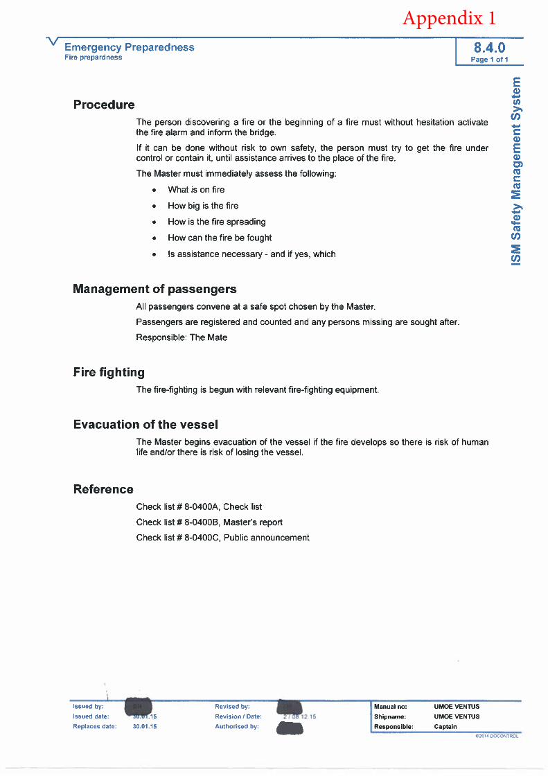
Appendix 1
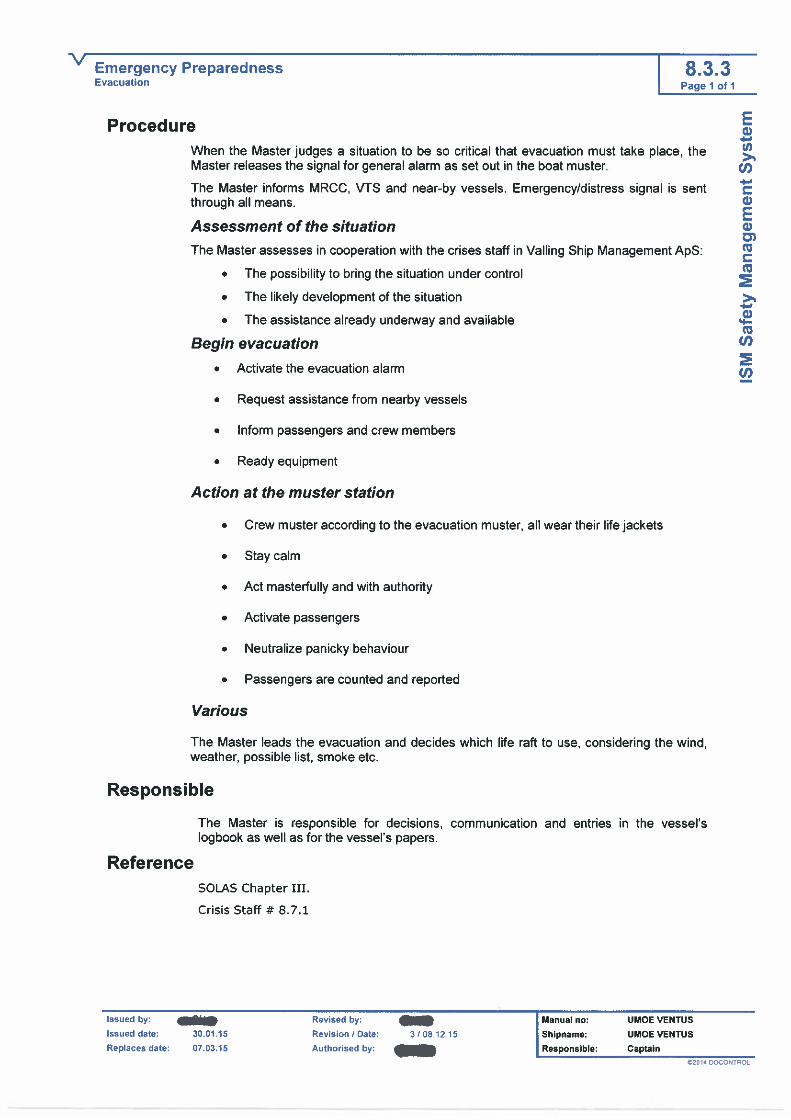
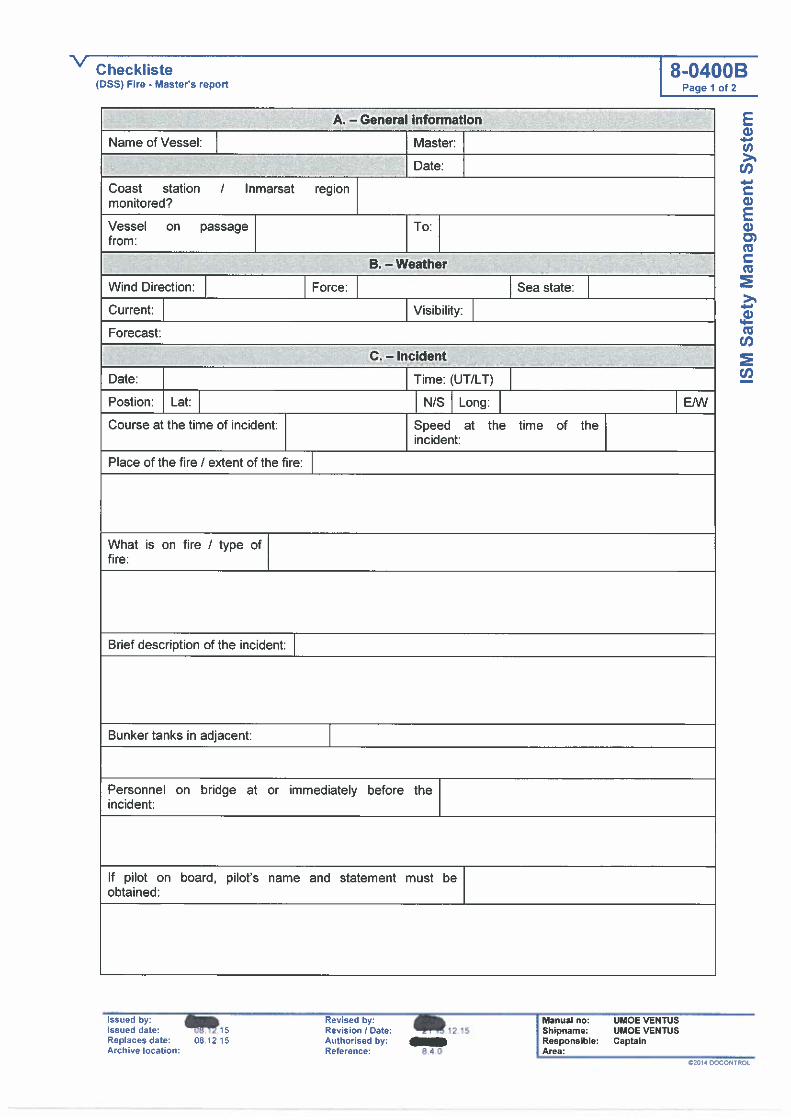

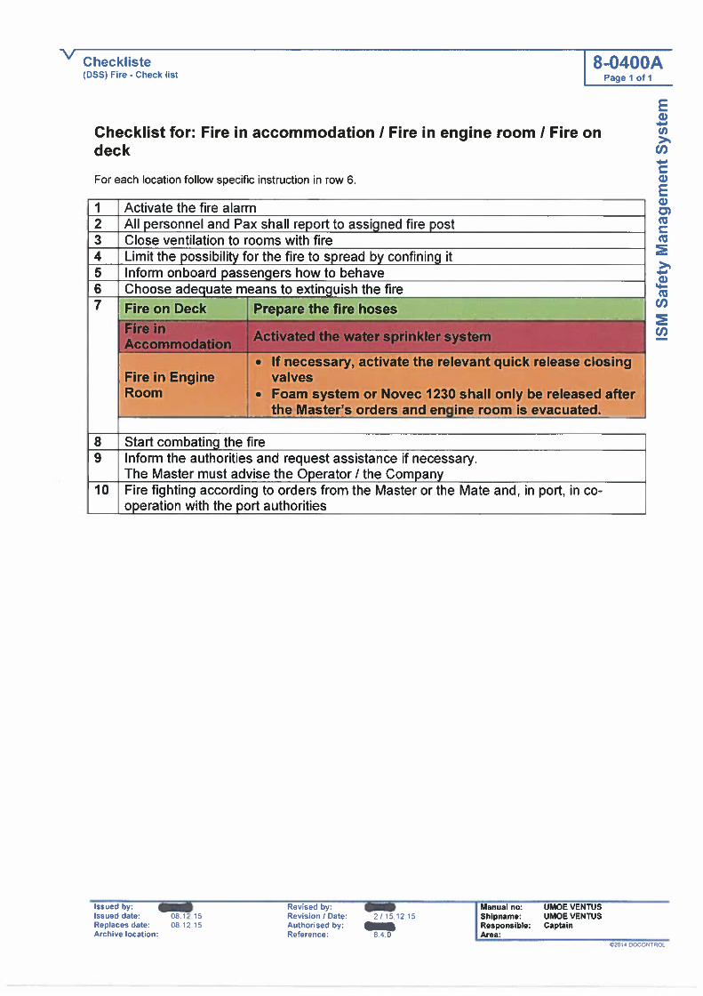
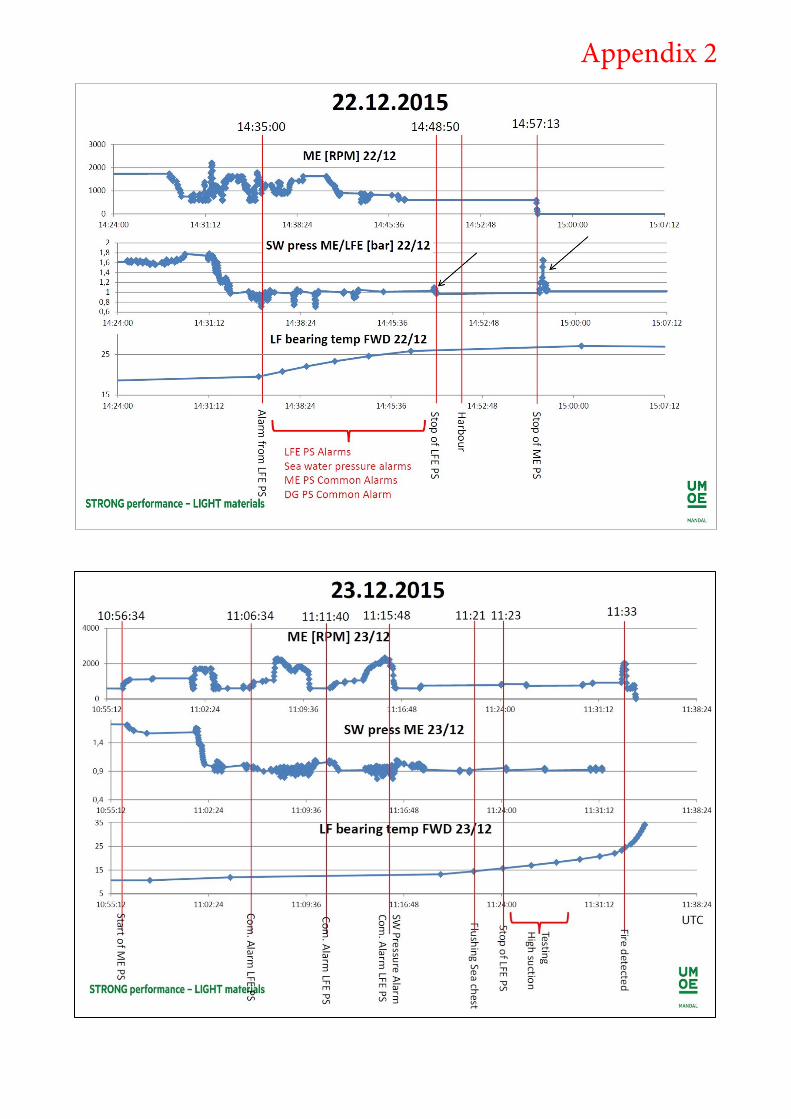
Appendix 2

Test Reg.no. 12
Danish Institute of Fire and Security Technology
Jernholmen 12, DK-2650 Hvidovre · Phone: +45 36 34 90 00 · E-mail: [email protected] · www.dbi-net.dk
D B I
Test report
Sandwich panels from ship
Name of client: Den Maritime Havarikommission
File no.: PFO10081A
Date: 2016-05-25
Pages: 11 Encl.: 9
Ref: MPA / DHL
08 Fall
Appendix 3
D B I
Page 2 of 11
File: PFO10081A Date: 2016-05-25
Client information
Client: Den Maritime Havarikommission
Address: Carl Jacobsens Vej 29
DK-2500 Valby
Denmark
The results relate only to the items tested. The test report should only be reproduced in extenso - in extracts
only with a written agreement with this institute.
Executive summery
The conclusion on ignition temperature is that the White panel can ignite in the smoke gas temperature range
of approx. 275-315 °C and the Untreated panel in the range of approx. 330-370 °C. This gas temperature should be measured 5mm above the surface using an ø1mm thermocouple. The investigation has been
conducted in the cone calorimeter.
“Ignition temperature” is a non-fundamental parameter that should be used with care. Ignition occurs when the right smoke gas temperature and the right smoke gas/oxygen ratio are present – this is never the same
in each test. Is either “correct” temperature or “correct” smoke gas/oxygen ratio missing - no ignition occurs.
Furthermore temperature is device dependent measurement.
DBI refers to the subsequent text which provide insight into the study forming the basis for this statement

D B I
Page 3 of 11
File: PFO10081A Date: 2016-05-25
Products Sandwich panels.
Description
Hull construction material for ships.
Manufacturer Not stated.
Purpose of tests In connection with fire accident of the ship named Umoe Ventus the client desired an investigation on the
ignition properties for the sampled products. The products have been subjected to the test procedures ISO
5660-1 and with additional ad hoc temperature measurements on the surface and above the surface of the product.
Sample 2016-05-11 DBI - Danish Institute of Fire and Security Technology received the following sample:
- 2 sandwich panels with white paint on one side with dimension 500 mm x 500 mm x 42.5 mm. One
panel was marked “AB-A7-KB40-A7 Skott LFR”. This panel type is designated “White panel” in this
report.
- 2 sandwich panels without paint with dimension 500 mm x 500 mm x 42.5 mm. One panel was marked “1-23-226-005”. This panel type is designated “Untreated panel” in this report.
All panels consisted of approx. 40 mm foam with approx. 1 mm glass fiber on both sides.
The weight per unit area of the White panel at 20°C (undried) was 8.4 kg/m2 at the state of receipt as determined by weight and measures of the sample.
The weight per unit area of the Untreated panel at 20°C (undried) was 7.9 kg/m2 at the state of receipt as
determined by weight and measures of the sample.
Conditioning 2015-05-13 the specimens were stored in a conditioning room with an atmosphere of relative humidity of 50
5% at a temperature of 23 2 C. The specimens were kept in this room until the tests were performed.
Test method The tests were performed in accordance with:
ISO 5660-1:2015 Reaction-to-fire tests – Heat release, smoke production and mass loss rate -
Part 1: Heat release rate (cone calorimeter method) and smoke production rate (dynamic measurement)
D B I
Page 4 of 11
File: PFO10081A Date: 2016-05-25
Test results 1.1 Test overview
Table 1 shows the overview of the performed tests with ignition results. The temperatures listed in Table 1 are average values in cases where more than one thermocouple was used. The ignition time and
temperatures are determined by the measuring point where a steep temperature rise is found which. The
temperatures were logged with a scan rate of 2 seconds. The found ignitions times by thermal measurement varies from the ISO 5660-1 shown in the following tables due the ISO 5660-1 data was logged with a scan
rate of 3 seconds.
Temperature measurements on and above the specimen were conducted with 1 mm sheathed K-type elements. Surface measurements were performed with the thermocouple place at an angle
of approx. 45 °C to the horizontal plane.
After test 9 it was decided to increase the number of temperature measurements and also measure the air
temperature above the specimen. Air temperatures measurements were performed with a distance of the thermocouple of approx. 5 mm to the surface.
Temperature graphs are shown in enclosure 1-5.
1.2 ISO 5660-1 results
Irradiance level: performed with varying irradiance levels (see tables) and all performed without spark igniter.
Orientation: Horizontal.
The retainer frame was used. In order to protect the foam of cut edges - which was assumed to have worse reaction fire properties than the glass fiber surface - a 13 mm ceramic fibre blanket was installed between the
specimen and the retainer frame outside the exposed area. The layer was compressed to approx. 4 mm.
Above the retainer frame a square perimeter of 13 mm ceramic fibre blanket was installed in order to reduce the heat flux of the steel sides of the frame retainer.
The specimen was laid onto one layer of 13 mm ceramic fibre blanket with a density of 65 kg/m³ taken from
DBI’s stock.
When testing the foam directly in test No. 18 and 20 - three layers of 13 mm ceramic fibre blanket were
used.
Volume flow was set to 24 ± 2 l/s.
All tests were performed with a distance of 60 mm between the cone and the specimens’ surface in order to
make room for thermal measurements.
The ISO 5660-1 test results where ignition occurred are shown in the following tables 2-5.
Graphs of heat release rate and smoke production rate for tests where ignition occurred are shown in
enclosure 6-9

D B I
Page 5 of 11
File: PFO10081A Date: 2016-05-25
Test no.
Surface
Heat flux (kW/m
2)
Amount of thermal couples on surface
Amount of thermal couples above surface
ISO 5660 measure ments
Ignition Ignition time (s)
Ignition tempe rature surface (°C)
Ignition tempera ture above specimen (°C)
Test 1 Untreated panel 10 1 0 no no - - -
Test 2 White panel 10 1 0 no no - - -
Test 3 Untreated panel 20 1 0 no no - - -
Test 4 White panel 20 1 0 no no - - -
Test 5 Untreated panel 30 1 0 no yes 248 439 -
Test 6 Untreated panel 25 1 0 no no - - -
Test 7 White panel 30 1 0 yes yes 158 454 -
Test 8 White panel 30 1 0 yes nej - - -
Test 9 White panel 30 1 0 yes yes 138 380 -
Test 10 White panel 35 2 2 yes yes 64 357 274
Test 11 White panel 35 2 2 yes yes 76 367 292
Test 12 White panel 35 2 1 yes yes 74 370 315
Test 13 Untreated panel 35 3 1 yes yes 78 384 367
Test 14 Untreated panel 35 3 1 yes yes 76 387 332
Test 15 Untreated panel 35 2 2 yes yes 90 428 341
Test 16 Untreated panel 30 2 2 no no - - -
Test 17 Untreated panel 30 2 2 yes no - - -
Test 18 Foam 30 2 2 yes no - - -
Test 19 Untreated panel 32.5 2 2 yes no - - -
Test 20 Foam 35 2 2 yes yes 758 521 378
Test 21 Untreated panel 35 2 2 yes yes 72 380 333
Table 1

D B I
Page 6 of 11
File: PFO10081A Date: 2016-05-25
White panel
Test no. 7 9 Average
Flux level (kW/m2) 30 30 -
Exposed area As, (m2) 0.008836 0.008836 -
Calibration constant C 0.0476 0.0476 -
Mass before, mi (g) 84 85 85
Mass after, mf (g) 53 50 52
Mass loss, (g) 31 25 28
Flashing, tflash (s) - -
Ignition, tign(s) 159 138 148
All flaming ceased, text (s) 447 345 391
Test time, ttest (s) 1197 1746 -
Peak heat release rate, qmax
(kW/m²) 292 284 288
Total heat produced, THR (MJ/m²)
39 37 38
Average heat release, 3 min, q180 (kW/m²), after ignition
173 171 172
Average heat release, 5 min,
q300 (kW/m²), after ignition 116 109 113
Maximum Arhe, Marhe (kW/m²)
95 100 98
Peak smoke production rate,
RSP (m2/m2/s) 17 17 17
Total smoke produced, SA (m2/m²)
2537 2125 2331
Total smoke produced over the
non-flaming phase, SA,1 (m2/m²)
216 112 164
Total smoke produced over the
flaming phase, SA,2 (m2/m²) 2321 2013 2167
Table 2

D B I
Page 7 of 11
File: PFO10081A Date: 2016-05-25
White panel
Test no. 10 11 12 Average
Flux level (kW/m2) 35 35 35 -
Exposed area As, (m2) 0.008836 0.008836 0.008836 -
Calibration constant C 0.048 0.048 0.048 -
Mass before, mi (g) 86 86 86 86
Mass after, mf (g) 51 52 50 51
Mass loss, (g) 35 34 36 35
Flashing, tflash (s) - - - -
Ignition, tign(s) 63 78 75 72
All flaming ceased, text (s) 450 465 627 514
Test time, ttest (s) 1299 1041 1107 -
Peak heat release rate, qmax
(kW/m²) 251 260 310 273
Total heat produced, THR (MJ/m²)
40 48 44 44
Average heat release, 3 min, q180 (kW/m²), after ignition
153 167 156 159
Average heat release, 5 min,
q300 (kW/m²), after ignition 106 130 107 114
Maximum Arhe, Marhe (kW/m²)
122 120 128 123
Peak smoke production rate,
RSP (m2/m2/s) 14 15 16 15
Total smoke produced, SA (m2/m²)
1731 2078 1675 1828
Total smoke produced over the
non-flaming phase, SA,1 (m2/m²)
15 20 42 26
Total smoke produced over the
flaming phase, SA,2 (m2/m²) 1716 2058 1633 1802
Table 3

D B I
Page 8 of 11
File: PFO10081A Date: 2016-05-25
Untreated panel
Test no. 13 14 15 21 Average
Flux level (kW/m2) 35 35 35 35 -
Exposed area As, (m2) 0.008836 0.008836 0.008836 0.008836 -
Calibration constant C 0.048 0.048 0.048 0.048 -
Mass before, mi (g) 83 83 84 83 86
Mass after, mf (g) 50 53 52 53 51
Mass loss, (g) 33 30 32 30 35
Flashing, tflash (s) - - - - -
Ignition, tign(s) 78 75 90 75 80
All flaming ceased, text (s) 636 261 633 1020 638
Test time, ttest (s) 897 846 1110 1023 -
Peak heat release rate, qmax
(kW/m²) 281 309 291 258 285
Total heat produced, THR (MJ/m²)
51 30 43 54 45
Average heat release, 3 min, q180 (kW/m²), after ignition
178 152 157 172 165
Average heat release, 5 min,
q300 (kW/m²), after ignition 136 93 114 126 117
Maximum Arhe, Marhe (kW/m²)
127 127 109 126 122
Peak smoke production rate,
RSP (m2/m2/s) 19 21 19 18 19
Total smoke produced, SA (m2/m²)
2986 2032 2526 3267 2703
Total smoke produced over
the non-flaming phase, SA,1 (m2/m²)
22 20 52 22 29
Total smoke produced over
the flaming phase, SA,2 (m2/m²)
2965 2013 2474 3245 2674
Table 4
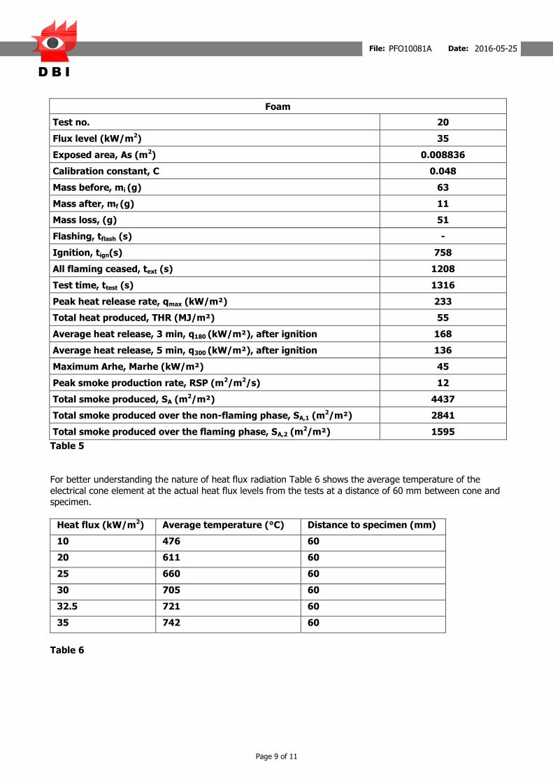
D B I
Page 9 of 11
File: PFO10081A Date: 2016-05-25
Foam
Test no. 20
Flux level (kW/m2) 35
Exposed area, As (m2) 0.008836
Calibration constant, C 0.048
Mass before, mi (g) 63
Mass after, mf (g) 11
Mass loss, (g) 51
Flashing, tflash (s) -
Ignition, tign(s) 758
All flaming ceased, text (s) 1208
Test time, ttest (s) 1316
Peak heat release rate, qmax (kW/m²) 233
Total heat produced, THR (MJ/m²) 55
Average heat release, 3 min, q180 (kW/m²), after ignition 168
Average heat release, 5 min, q300 (kW/m²), after ignition 136
Maximum Arhe, Marhe (kW/m²) 45
Peak smoke production rate, RSP (m2/m2/s) 12
Total smoke produced, SA (m2/m²) 4437
Total smoke produced over the non-flaming phase, SA,1 (m2/m²) 2841
Total smoke produced over the flaming phase, SA,2 (m2/m²) 1595
Table 5
For better understanding the nature of heat flux radiation Table 6 shows the average temperature of the
electrical cone element at the actual heat flux levels from the tests at a distance of 60 mm between cone and specimen.
Heat flux (kW/m2) Average temperature (°C) Distance to specimen (mm)
10 476 60
20 611 60
25 660 60
30 705 60
32.5 721 60
35 742 60
Table 6

D B I
Page 10 of 11
File: PFO10081A Date: 2016-05-25
Conclusion It was found that both the White panel and the Untreated panel could ignite at a flux level of 30 kW/m2 – however as Table 1 shows ignition did not always occur meaning 30 kW/m2 must the lower limit of ignition for
both panel types. As shown in the temperature curves in enclosure 1-6 unignited specimen follow more or less the same temperature curves as the ones that did ignite.
At 35 kW/m2 all panels ignited during the tests. The White panel ignited in average after 72 seconds. For the White panel the average surface temperature at ignition was found to be 374 °C and the average
temperature above the specimen to be 294 °C.
At the same flux level the Untreated panel ignited in average after 80 seconds. For the Untreated panel the
average surface temperature at ignition was found to be 395 °C and the average temperature above the specimen to be 343 °C.
Test 15 shows that a prolonged ignition time apparently results in a higher surface temperature whereas the
air temperature is on the level with the average value. In regard to surface temperature this is also the case with test 7 and 9.
It also seems that the surface temperature at ignition found at the 30 kW/m2 are higher than for the 35 kW/m2 tests – though ignition data for 30 kW/m2 is scarce.
In regard to ignition the White panel was found to be only slightly worse than the Untreated panel.
Tests without pilot burner or spark ignition tend to vary much more in ignition time than tests with pilot burner or spark ignition. Ignition occurs when the right smoke gas temperature and the right smoke
gas/oxygen ratio are present – this is never the same in each test. The tests where ignition did not occur were due to the fact that the temperature and ratio were never there. It is also possible that the variation of
fire retardant in the panels causes the different ignition behaviour - for instance one test at 32.5 kW/m2
showed no ignition – based on former results it was expected to ignite.
Two tests were conducted with the foam directly exposed. The test at 30 kW/m2 showed no ignition as most as the other tests show. At 35 kW/m2 the ignition came significantly later compared to the other tests. It was
also noted that the smoke colour was lighter than observed in the other tests indicating a higher amount of less volatile gas compounds or water. The surface temperature at ignition was found to be 521 °C and the
temperature above the specimen to be 378 °C.
As the occurrence of ignition is correlated to the smoke gas temperature and the smoke gas/oxygen ratio the
surface temperature is not a good indication for determining ignition. The smoke gas temperature is a better parameter for determining ignition.
The conclusion on ignition temperature is that the White panel can ignite in the smoke gas temperature range of approx. 275-315 °C and the Untreated panel in the range of approx. 330-370 °C.
In regard to heat release rate the results no significant difference was found between the White and the
Untreated panel.

D B I
Page 11 of 11
File: PFO10081A Date: 2016-05-25
Statement These test results relate only to the behaviour of the product under the particular conditions of the test, and
they are not intended to be the sole criterion for assessing the potential fire hazard of the product in use.
Dan Lauridsen
M.Sc. (Civ.Eng.)
Martin Pauner
M.Sc.Civ.Eng
Den Maritime Havarikommission Carl Jacobsens Vej 29
DK-2500 Valby
Denmark

D B I
Enclosure 1 of 9
File: PFO10081A Date: 2016-05-25

D B I
Enclosure 2 of 9
File: PFO10081A Date: 2016-05-25

D B I
Enclosure 3 of 9
File: PFO10081A Date: 2016-05-25

D B I
Enclosure 4 of 9
File: PFO10081A Date: 2016-05-25

D B I
Enclosure 5 of 9
File: PFO10081A Date: 2016-05-25
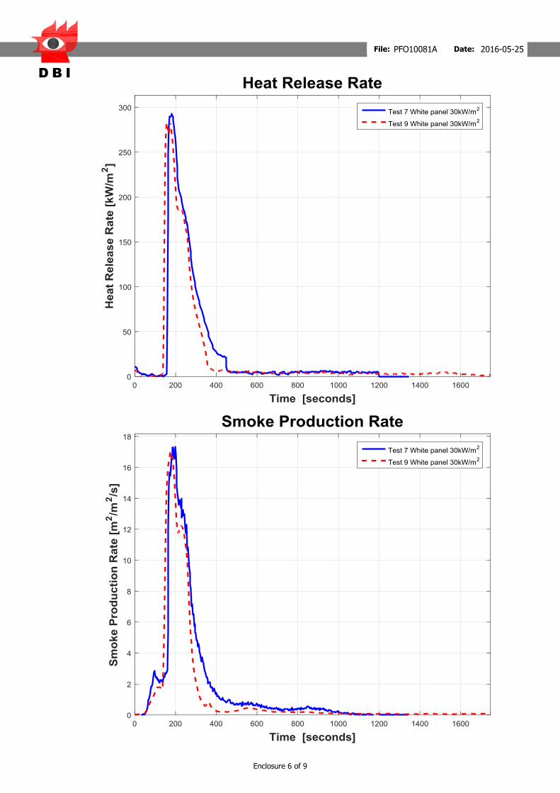
D B I
Enclosure 6 of 9
File: PFO10081A Date: 2016-05-25
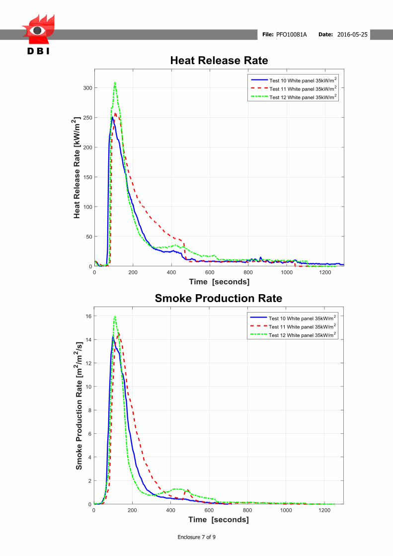
D B I
Enclosure 7 of 9
File: PFO10081A Date: 2016-05-25

D B I
Enclosure 8 of 9
File: PFO10081A Date: 2016-05-25
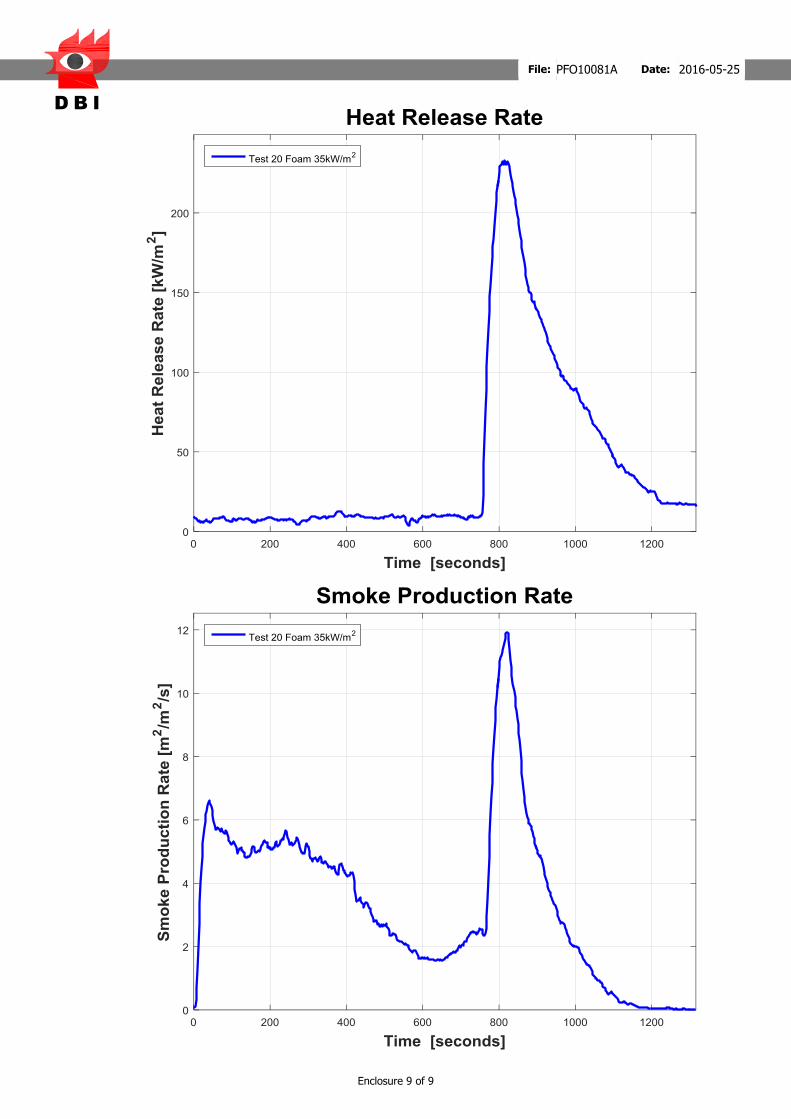
D B I
Enclosure 9 of 9
File: PFO10081A Date: 2016-05-25


