

USPAS June 2002Materials, Fabrication, Joint DesignPage 1
Lou Bertolini Lawrence Livermore National Laboratory
June 10-14, 2002
The US Particle Accelerator SchoolMaterials, Fabrication Techniques, and Joint
Designs
The US Particle Accelerator SchoolMaterials, Fabrication Techniques, and Joint
Designs

USPAS June 2002Materials, Fabrication, Joint DesignPage 2
Stainless Steel• High strength, moderate formability, excellent weldability.
• Can be extruded in simple shapes
• 304 SS, least expensive304L SS, most commonly used in vacuum, a little more expensive316 SS, most expensive, resistant to chemical attack, welds are non-magnetic
• Wide variety of circular tubes and pipes available (seamless & welded)
• Outgassing rates can be decreased by employing good machining techniques, chemical cleaning and baking (up to 900oC)
• Thermal and electrical conductivity is poor

USPAS June 2002Materials, Fabrication, Joint DesignPage 3
Typical Physical Properties for Stainless Steels
Cu 100%
C 0.08%Cr 17%Mn 2%Mo 2.5%Fe 65%Ni 12%P 0.045%S 0.03%Si 1%
C 0.03%Cr 18-20%Mn 2%Fe 66-74%Ni 8-12%P 0.045%S 0.03%Si 1%
C 0.08%Cr 18-20%Mn 2%Fe 66-74%Ni 8-10.5%P 0.045%S 0.03%Si 1%
Composition:
17x10628x10628.5x10628.6x106Mod. Of Elasticity (psi)
101Elect. Conduct. (% IACS*)
17.5x10-616.0x10-617.2x10-617.2x10⁻⁶Coeff. Of Therm. Exp. (oC-1)39116.316.216.2Therm. Conduct. (W/m-K)
1.71 x 10-67.4 x 10-57.2 x 10-57.2 x 10-5Electrical Resistivity (W-cm)8.928.08.08.0Density (g/cc)1083138514251427Melting Point (oC)
OFE Cu316304L 304Property

USPAS June 2002Materials, Fabrication, Joint DesignPage 4
Typical Mechanical Properties for Stainless Steels
16.728.028.628.6Modulus of Elasticity (ksi)
31.536.330.531.2Yield Strength (ksi)
115193197197Modulus of Elasticity (Mpa)
55555870Elongation (%)
217250210215Yield Strength (Mpa)
49.081.981.873.2Tensile Strength (ksi)
338565564505Tensile Strength (MPa)
OFE Cu316304L 304Property
Ref. www.matls.com

USPAS June 2002Materials, Fabrication, Joint DesignPage 5
Tubing - Seamless and Welded
Seamless (extruded) Welded (rolled & welded)
Cleaner to start with and easier to clean
Rolling can embed dirt in the surface

USPAS June 2002Materials, Fabrication, Joint DesignPage 6
PEP-II Straight Section Stainless Steel Beampipes
Copper-plated Seamless Stainless Steel Tube
Stainless Steel Double-wall Tube

USPAS June 2002Materials, Fabrication, Joint DesignPage 7
Formed and Welded Stainless Steel Chamber - Manpower Intensive
Q4 Chamber Parts
Q5 Chamber

USPAS June 2002Materials, Fabrication, Joint DesignPage 8
Aluminum• Moderate strength, good formability, easy to machine
• Can be extruded in complicated shapes
• 6061-T6 is the most common aluminum alloy for vacuum components
• 5083 is a good alloy for welding
• Aluminum is much cheaper to machine than stainless steel (2x to 3x cheaper)
• Special care must be taken in the design of welds and the techniques used due to higher thermal conductivity and thermal expansion (30% > SS)
• Surface anodizing degrades outgassing characteristics, but improves chemical resistance
USPAS June 2002Materials, Fabrication, Joint DesignPage 9
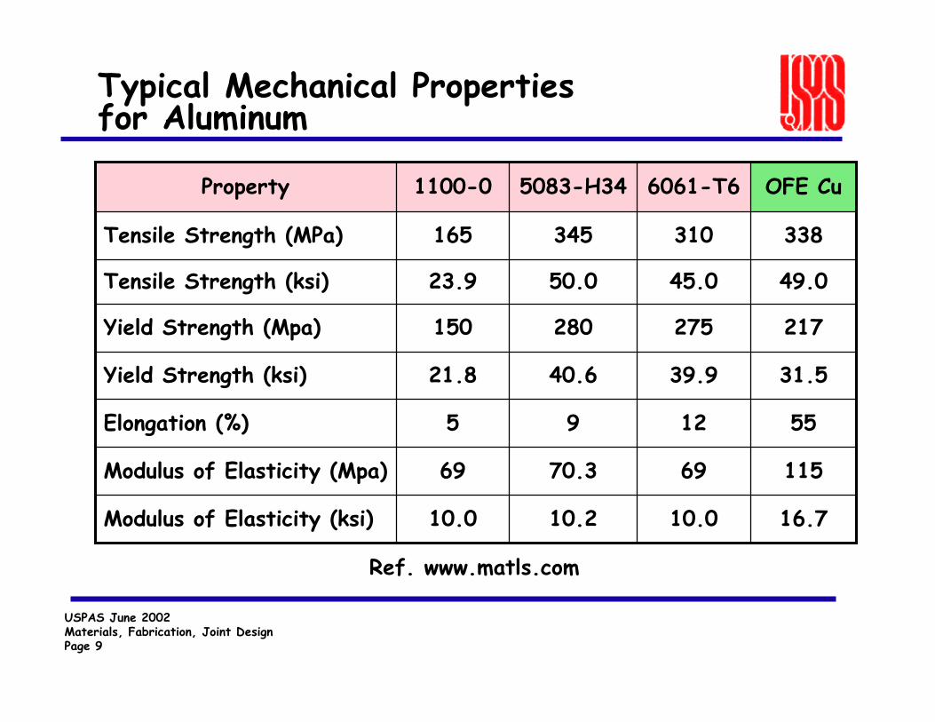
Typical Mechanical Properties for Aluminum
16.710.010.210.0Modulus of Elasticity (ksi)
31.539.940.621.8Yield Strength (ksi)
1156970.369Modulus of Elasticity (Mpa)
551295Elongation (%)
217275280150Yield Strength (Mpa)
49.045.050.023.9Tensile Strength (ksi)
338310345165Tensile Strength (MPa)
OFE Cu6061-T65083-H34 1100-0Property
Ref. www.matls.com

USPAS June 2002Materials, Fabrication, Joint DesignPage 10
Typical Physical Properties for Aluminum
Cu 100%
Al 98%Cu 0.15-0.4%Cr 0.04-0.35%Mg 0.8-1.2%Mn 0.15%Fe 0.7%Si 0.4-0.8%Ti 0.15%Zn 0.25%
Al 94.8%Cu 0.1%Cr 0.05-0.25%Mg 4-4.9%Mn 0.4-1%Fe 0.4%Si 0.4%Ti 0.15%Zn 0.25%
Al 99%Cu 0.05-0.2%Mn 0.05%Si+Fe 0.95%Zn 0.1%
Composition:
0.3850.8960.90.904Heat Capacity (J/g-oC)
17.5x10-625.2x10-626x10-625.5x10⁻⁶Coeff. Of Therm. Exp. (oC-1)
391167117218Therm. Conduct. (W/m-K)
1.7x10-63x10-65.9x10-63x10-6Electrical Resistivity (W-cm)
8.922.72.662.71Density (g/cc)
1083582591643Melting Point (oC)
OFE Cu6061-T65083-H34 1100-0Property
Ref. www.matls.com

USPAS June 2002Materials, Fabrication, Joint DesignPage 11
Aluminum Beam Pipe Spool
Aluminum Tube
Gage Port w/ CurrentReturn Bars
Al/SS Bi-metallicConflat Flange

USPAS June 2002Materials, Fabrication, Joint DesignPage 12
Machined Aluminum Vacuum Chamber

USPAS June 2002Materials, Fabrication, Joint DesignPage 13
Aluminum Extrusions

USPAS June 2002Materials, Fabrication, Joint DesignPage 14
Copper
• Typical copper alloys are C10100, C26800, C61400, C17200
• Low-to-moderate strength, good formability
• Excellent electrical and thermal characteristics
• Difficult to weld (e-beam welding is best)
• May be joined by welding, brazing, and soldering
• Good outgassing characteristics, rates can be decreased by following good machining techniques, chemical and baking (~200°C)

USPAS June 2002Materials, Fabrication, Joint DesignPage 15
Copper Extrusions
Cooling Bar Extrusion
“Dipole” Chamber Extrusion
Screen Extrusion
USPAS June 2002Materials, Fabrication, Joint DesignPage 16
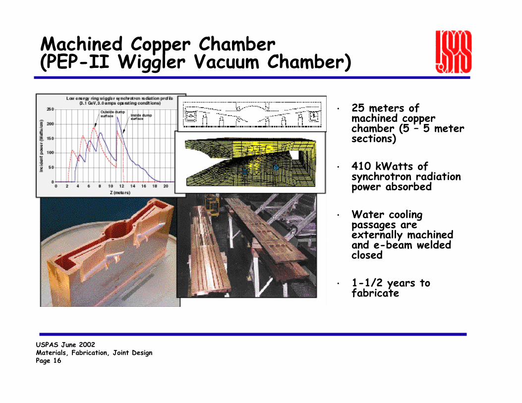
Machined Copper Chamber (PEP-II Wiggler Vacuum Chamber)
• 25 meters of machined copper chamber (5 – 5 meter sections)
• 410 kWatts of synchrotron radiation power absorbed
• Water cooling passages are externally machined and e-beam welded closed
• 1-1/2 years to fabricate

USPAS June 2002Materials, Fabrication, Joint DesignPage 17
Machined Copper Chamber (SPEAR3)

USPAS June 2002Materials, Fabrication, Joint DesignPage 18
PEP-II HER High Power Synchrotron Radiation Dump Chamber

USPAS June 2002Materials, Fabrication, Joint DesignPage 19
Machined Copper Chamber (PEP-II RF Cavities)
• 26 cavities
• $4M total fabrication cost
• Integral cooling channels with electroformed cover
• 5 axis machining
• e-beam welded
• 17 separate manufacturing steps

USPAS June 2002Materials, Fabrication, Joint DesignPage 20
Glidcop
• High strength, moderate formability, poor weldability.
• Available in sheets, plate, wire, and extruded rounds.• Maintains good mechanical strength after brazing.• Outgassng rates are similar to pure copper.• Thermal and electrical properties are good.
Glidcop is pure copper with Al2O3 dispersed throughout.Glidcop is pure copper with Al2O3 dispersed throughout.
2.71.197.398.9Glidcop AL-60C157601.20.598.89.5Glidcop AL-25 C15725
0.70.399.399.7Glidcop AL-15C15715Vol %Wt %Vol %Wt %SCM Metal Prod.UNS
Al2O3CopperGrade Designations

USPAS June 2002Materials, Fabrication, Joint DesignPage 21
Glidcop Physical Properties
19x10619x10619x10619x106Mod. Of Elasticity (psi)
1017887 92Elect. Conduct. (% IACS*)
17.7x10-616.6x10-616.6x10-616.6x10⁻⁶Coeff. Of Therm. Exp. (oC-1)
391322344365Therm. Conduct. (W/m-K)
10.2013.2911.91 11.19Electrical Resistivity (W)
0.3230.3180.3200.321Density (lb/in3)
1083108310831083Melting Point (oC)
OFE CuC15760C15725 C15715Property
* International Annealed copper Standard

USPAS June 2002Materials, Fabrication, Joint DesignPage 22
Welding
• Welding is the most common method for joining metals in vacuum systems.
• Inert gas welding is the most common type of welding (TIG, MIG).
• Joint design is critical from vacuum, metallurgical and distortion standpoints.
• Cleanliness is essential.• Other welding processes to consider are electron beam
and laser welding.
Welding is the process where two materials are joined by fusionWelding is the process where two materials are joined by fusion

USPAS June 2002Materials, Fabrication, Joint DesignPage 23
Welding Aluminum
• Low melting point, relatively high thermal conductivity, and high rate of thermal expansion make welding aluminum more problematic than stainless steel.
• Aluminum requires:1. High welding speeds (higher current densities)2. Good material purity and cleanliness3. Good joint design
• Aluminum welds have a tendency to crack from excessive shrinkage stresses due to their high rate of thermal contraction.

USPAS June 2002Materials, Fabrication, Joint DesignPage 24
Welding Copper
• The high thermal conductivity of copper makes welding difficult.Heating causes the copper to recrystalize forming large grain size and annealing. Distortion is also a big problem.
• Copper requires:1. Very high welding speeds2. Excellent material purity (OFE copper) and cleanliness.3. Good joint design
• Electron beam welding is an excellent process for welding copper.

USPAS June 2002Materials, Fabrication, Joint DesignPage 25
Electron Beam Welding (EBW)
• EBW provides extremely high energy density in its focused beam producing deep, narrow welds.
• This rapid welding process minimizes distortion and the heat affected zone.
• A disadvantage of EBW is that the process takes place under vacuum (P = 10-4 Torr):— Extensive fixturing required— High cost— Complexity— Welds are not cleanable

USPAS June 2002Materials, Fabrication, Joint DesignPage 26
Copper chambers ready for electron beam welding
RF Cavity HER Quadrupole Chamber

USPAS June 2002Materials, Fabrication, Joint DesignPage 27
SLAC Electron Beam Welder
USPAS June 2002Materials, Fabrication, Joint DesignPage 28
Soldering
• Soldering is differentiated from brazing primarily by the melting temperature of the filler metals. Solder alloys melt below 450°C.
• All soft solders are unacceptable for UHV systems because:- They contain Pb, Sn, Zr, Bi, Zn (vapor pressures are too high)- System bake-out temperatures typically exceed alloy melting
points.
• Most silver solders are unacceptable.
Soldering is the process where materials are joined together by the flow of a “filler metal” through capillary action.
Soldering is the process where materials are joined together by the flow of a “filler metal” through capillary action.

USPAS June 2002Materials, Fabrication, Joint DesignPage 29
Brazing
• There are several different brazing processes:1. Torch2. Furnace3. Induction4. Dip5. Resistance
• Brazing can be used to join many dissimilar metals. The notable exceptions are aluminum and magnesium.
• Cleanliness is important in brazing. Cleanliness is maintained by use of a flux or by controlling the atmosphere (vacuum or H2).
Brazing is the process where two dissimilar materials are joinedtogether by the flow of a “filler metal” through capillary action.Brazing is the process where two dissimilar materials are joinedtogether by the flow of a “filler metal” through capillary action.

USPAS June 2002Materials, Fabrication, Joint DesignPage 30
Brazing (cont.)
• Filler metals come in the form of wire, foils, or paste.
• Filler metals are selected to have melting points below that of the base metal.
• Multiple braze steps are possible by choosing alloys of differing melting points and proceeding sequentially from highest to lowest temperature.
• Braze joints require tight tolerances for a good fit (0.002” to 0.004”).

USPAS June 2002Materials, Fabrication, Joint DesignPage 31
Typical Braze Alloys for UHV Components
Time @ Temperature: 2-20 minutes
81.5% Au, 16.5% Cu, 2% Ni925oCAu-Cu-
Ni
35% Au, 65% Cu1010oC35/65 Au-Cu
50% Au, 50% Cu970oC50/50 Au-Cu
82% Au, 18% Ni950oCBAu -4
80% Au, 20% Cu890oCBAu -2
CompositionBrazing TemperatureAlloy

USPAS June 2002Materials, Fabrication, Joint DesignPage 32
There are a variety of metal seals available for vacuum systems
• Copper (Conflats, wire, VATSEALS)
• Indium Foil or Wire
• Aluminum Wire
• Tin Wire or Foil
• Gold/Silver Wire

USPAS June 2002Materials, Fabrication, Joint DesignPage 33
Conflat Flanges
• Vacuum rated to 1 x 10-13 Torr
• Temperature rated to 450°C
• Typical size range: 1-1/3”-16-1/2” od
• Flanges come in a variety of configurations- rotatable- non-rotatable- tapped or clearance bolt holes- double-sided
• Flanges are genderless

USPAS June 2002Materials, Fabrication, Joint DesignPage 34
Conflat Flange Designations

USPAS June 2002Materials, Fabrication, Joint DesignPage 35
Wire Seal Flanges
• Vacuum rated to 1 x 10-13 Torr
• Temperature rated to 450°C
• Typical size range: 10” - 20” od
• Warning – male and female flanges

USPAS June 2002Materials, Fabrication, Joint DesignPage 36
PEP-II Wiggler Vacuum Chamber Welded Flanges
Weld Joint
Structural Joint

USPAS June 2002Materials, Fabrication, Joint DesignPage 37
PEP-II LER Arc Magnet Chamber Tin-Seal Flanges
Aluminum Raised-Face Flange with 0.010” thick Tin-Seal
Bellville Washers

USPAS June 2002Materials, Fabrication, Joint DesignPage 38
ANSI ASA Flanges
• Flanges come with either a flat-face or with an o-ring groove.
• Vacuum rated to 1 x 10⁻⁸ Torr(better suited to 1 x 10⁻⁶ Torr)
• Temperature rating is dependent on which elastomero-ring is used (usually 150°C)
• Typical size range: 1” to 12” dia.
USPAS June 2002Materials, Fabrication, Joint DesignPage 39
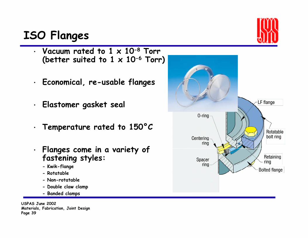
ISO Flanges• Vacuum rated to 1 x 10⁻⁸ Torr
(better suited to 1 x 10⁻⁶ Torr)
• Economical, re-usable flanges
• Elastomer gasket seal
• Temperature rated to 150°C
• Flanges come in a variety of fastening styles:- Kwik-flange- Rotatable- Non-rotatable- Double claw clamp- Banded clamps

USPAS June 2002Materials, Fabrication, Joint DesignPage 40
VATSEAL Flanges
Silverplated copper• Metal seal, bakeable to
300oC
• Custom sizes and shapes
• Radiation resistant
• UHV compatible
• Accelerator option - RF contact between flanges

USPAS June 2002Materials, Fabrication, Joint DesignPage 41
Example of a VATSEAL Flange Gasket

USPAS June 2002Materials, Fabrication, Joint DesignPage 42
Explosion Bonding allows for joining a variety of metals
• Plates Are Spaced Above Each Other with Ammonium Nitrate Explosives Above
• A Point Source Progressive Charge is Detonated and the Plates Accelerated to Contact
• An Ion Plasma Jet is Formed at the Contact Point Stripping Oxides and Contaminates from the Metal Surfaces
• Extreme pressures at Impact and Ultra Clean Surfaces
ExplosiveFlyer Plate
Explosive Bonding Event
Stainless
Aluminum Base PlateMetal Plasma
• Dissimilar Atoms Bonded Together
• Metallurgical Bond is made

USPAS June 2002Materials, Fabrication, Joint DesignPage 43
Atlas Technologies Bonding Matrix Copy Right Atlas Technologies January 1998
Alu
min
um
AL.
Allo
y
Chr
omiu
m
Cop
per
CU
Allo
y
Glid
Cop
Gol
d
Haf
nium
Indi
um
Iron
Lead
Mag
nesi
um
Mol
ydbe
num
Mol
y. A
lloy
Nic
kel,
(Inva
r)
Nio
bium
Pla
tinum
Rhe
nium
Silv
er
Ste
el, &
Allo
ys
Ste
el, M
ild
Sta
inle
ss S
teel
Tant
alum
Tin
Tita
nium
Tung
sten
Van
adiu
m
Zinc
Zirc
oniu
m
1 2 3 4 5 6 7 8 9 10 11 12 13 14 15 16 17 18 19 20 21 22 23 24 25 26 27 28 29Aluminum 1AL. Alloy 2Chromium 3Copper 4CU Alloy 5Gold 6GlidCop 7Hafnium 8Indium 9Iron 10Lead 11Magnesium 12Molydbenum 13Moly. Alloy 14Nickel, (Invar) 15Niobium 16Platinum 17Rhenium 18Silver 19Steel, & Alloys 20Steel, Mild 21Stainless Steel 22Tantalum 23Tin 24Titanium 25Tungsten 26Vanadium 27Zinc 28Zirconium 29
Bonding Capability Flange Metal Standards Beam Stop, Absorber Materials Super-conducting Flange Materials
Explosion Bonding Materials Matrix

USPAS June 2002Materials, Fabrication, Joint DesignPage 44
Stainless
Aluminum
Stainless
CopperTitanium
AL/SS Bond Interface
SS/AL Bond InterfacePatent# 5836623
• Diffusion Inhibiting LayersCopper and Titanium
InterlayerEnables Bonding AL/SS
• Vacuum:<1x10⁻¹⁰cc He/Sec
• Thermal:Peak 500C at weld up0-250C Operational
• MechanicalTensile 38,000 Psi,Shear 30,000 Psi

USPAS June 2002Materials, Fabrication, Joint DesignPage 45
Flange Production RecipePatent # 5836623
Detonator
Atlas FlangesProgressive Explosion
Non Bond Areas
1. Bond AL Plate to Ti Sheet Bond SS Plate to Cu Sheet
2. Bond AL/Ti Plate to SS/Cu Plate
3. Determine Non-Bond Areas of the SS/Cu/Ti/Al Plate
4. Water Cut Discs From the Plate
5. Machine Flanges from Discs

USPAS June 2002Materials, Fabrication, Joint DesignPage 46
Different applications for bi-metallic joints
Atlas Technologies
305-B Glen Cove RoadPort Townsend, WA 98368Ph: 360-385-3123, Fax [email protected] www.atlasbimetal.com


![Fabrication-aware Design with Intersecting Planar …...Y. Schwartzburg & M. Pauly / Fabrication-aware Design with Intersecting Planar Pieces Pop-up designs [Gla02,LSH10,LJGH11] aim](https://static.documents.pub/doc/80x56/5e46c57efdbb2f676a7c14c3/fabrication-aware-design-with-intersecting-planar-y-schwartzburg-m-pauly.jpg)


