

ME 111: Engineering Drawing
Lecture 408-08-2011
Engineering Curves and Theory of Projection
Indian Institute of Technology GuwahatiGuwahati – 781039
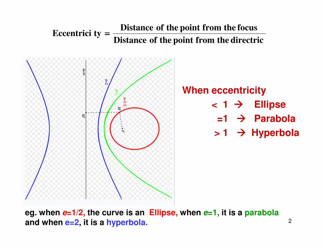
When eccentricity< 1 ���� Ellipse=1 ���� Parabola
directricthefrompointtheofDistancefocusthefrompointtheofDistancetyEccentrici ====
2
> 1 ���� Hyperbola
eg. when e=1/2, the curve is an Ellipse, when e=1, it is a parabola and when e=2, it is a hyperbola.

Focus-Directrix or Eccentricity MethodGiven : the distance of focus from the directrix and eccentricityExample : Draw an ellipse if the distance of focus from the directrix is 70
mm and the eccentricity is 3/4.1. Draw the directrix AB and
axis CC’
2. Mark F on CC’ such thatCF = 70 mm.
3. Divide CF into 7 equalparts and mark V at the
3
parts and mark V at thefourth division from C.Now, e = FV/ CV = 3/4.
4. At V, erect a perpendicularVB = VF. Join CB. ThroughF, draw a line at 45° to meetCB produced at D. ThroughD, drop a perpendicularDV’ on CC’. Mark O at themidpoint of V– V’.

Focus-Directrix or Eccentricity Method ( Continued)
5. With F as a centre and radius =1–1’, cut two arcs on theperpendicular through 1 tolocate P1 and P1’. Similarly,with F as centre and radii = 2–2’, 3–3’, etc., cut arcs on thecorresponding perpendicularsto locate P2 and P2’, P3 andP3’, etc. Also, cut similar arcson the perpendicular through
4
on the perpendicular throughO to locate V1 and V1’.
6. Draw a smooth closed curvepassing through V, P1, P/2, P/3,…, V1, …, V’, …, V1’, … P/3’,P/2’, P1’.
7. Mark F’ on CC’ such that V’ F’= VF.

Constructing a Parabola (Eccentricity Method)Example. Draw a parabola if the distance of the focus from the directrix is 60 mm.
1. Draw directrix AB and axis CC’ as shown.
2. Mark F on CC’ such that CF = 60 mm.
3. Mark V at the midpoint of CF. Therefore, e =VF/ VC = 1.
4. At V, erect a perpendicular VB = VF. Join CB.
5. Mark a few points, say, 1, 2, 3, … on VC’ anderect perpendiculars through them meeting
5
erect perpendiculars through them meetingCB produced at 1’, 2’, 3’, …
6. With F as a centre and radius = 1–1’, cut twoarcs on the perpendicular through 1 to locateP1 and P1’. Similarly, with F as a centre andradii = 2–2’, 3–3’, etc., cut arcs on thecorresponding perpendiculars to locate P2and P2’, P3 and P3’, etc.
7. Draw a smooth curve passing through V, P1,P2, P3 … P3’, P2’, P1’.
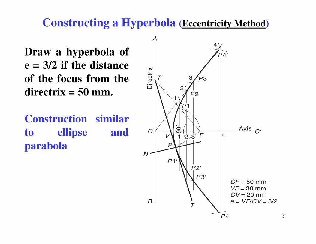
Constructing a Hyperbola (Eccentricity Method)
Draw a hyperbola ofe = 3/2 if the distanceof the focus from thedirectrix = 50 mm.
Construction similar
6
Construction similarto ellipse andparabola

Drawing Tangent and Normal to any conic
7
When a tangent at any point on the curve (P) is produced to meet thedirectrix, the line joining the focus with this meeting point (FT) will be atright angle to the line joining the focus with the point of contact (PF).
The normal to the curve at any point is perpendicular to the tangent atthat point.

Another definition of the ellipseAn ellipse is the set of all points in a plane for which the sum ofthe distances from the two fixed points (the foci) in the plane isconstant.
8

Arcs of Circle MethodGiven conditions: (1) the major axis and minor axis are known OR
(2) the major axis and the distance between the foci are knownDraw AB & CD perpendicular to eachother as the major diameter minordiameter respectively.With centre as C or D, and half the majordiameter as radius draw arcs to intersectthe major diameter to obtain the foci at Xand Y.Mark a number of points along line
9
Mark a number of points along linesegment XY and number them. Points neednot be equidistant.Set the compass to radius B-1 and drawtwo arcs, with Y as center. Set the compassto radius A1, and draw two arcs with X ascenter. Intersection points of the two arcsare points on the ellipse. Repeat this stepfor all the remaining points.Use the French curve to connect the points,thus drawing the ellipse.

Constructing an Ellipse (Concentric Circle Method)
Given:
Major axis and minor axis
10
• With center C, draw two concentric circles with diameters equal to major and minordiameters of the ellipse. Draw the major and minor diameters.
• Construct a line AB at any angle through C. Mark points D and E where the lineintersects the smaller circle.
• From points A and B, draw lines parallel to the minor diameter. Draw lines parallel tothe major diameter through D & E.
• The intersection of the lines from A and D is point F, and from B and E is point G.Points F & G lies on the ellipse.
• Extend lines FD & BG and lines AF and GE to obtain two more points in the otherquadrants.
• Repeat steps 2-6 to create more points in each quadrant and then draw a smoothcurve through the points.

Constructing a Parabola (Parallelogram Method)Example: Draw a parabola of base 100 mm and axis 50 mm if the axis
makes 70° to the base.
11
1. Draw the base RS = 100 mm and through its midpoint K, draw the axis KV = 50 mm, inclinedat 70° to RS. Draw a parallelogram RSMN such that SM is parallel and equal to KV.
2. Divide RN and RK into the same number of equal parts, say 5. Number the divisions as 1, 2, 3,4 and 1’, 2’, 3’, 4’, starting from R.
3. Join V–1, V–2, V–3 and V–4. Through 1’, 2’, 3’ and 4’, draw lines parallel to KV to meet V–1 atP1, V–2 at P2, V–3 at P3 and V–4 at P4, respectively.
4. Obtain P5, P6, P7 and P8 in the other half of the rectangle in a similar way. Alternatively, thesepoints can be obtained by drawing lines parallel to RS through P1, P2, P3 and P4. For example,draw P1– P8 such that P1– x = x– P8. Join P1, P2, P3 … P8 to obtain the parabola.

Hyperbola
A Hyperbola is obtainedwhen a section plane,parallel/inclined to the axiscuts the cone on one side ofthe axis.
12
A Rectangular Hyperbola isobtained when a section,parallel to the axis cuts thecone on one side of the axis.
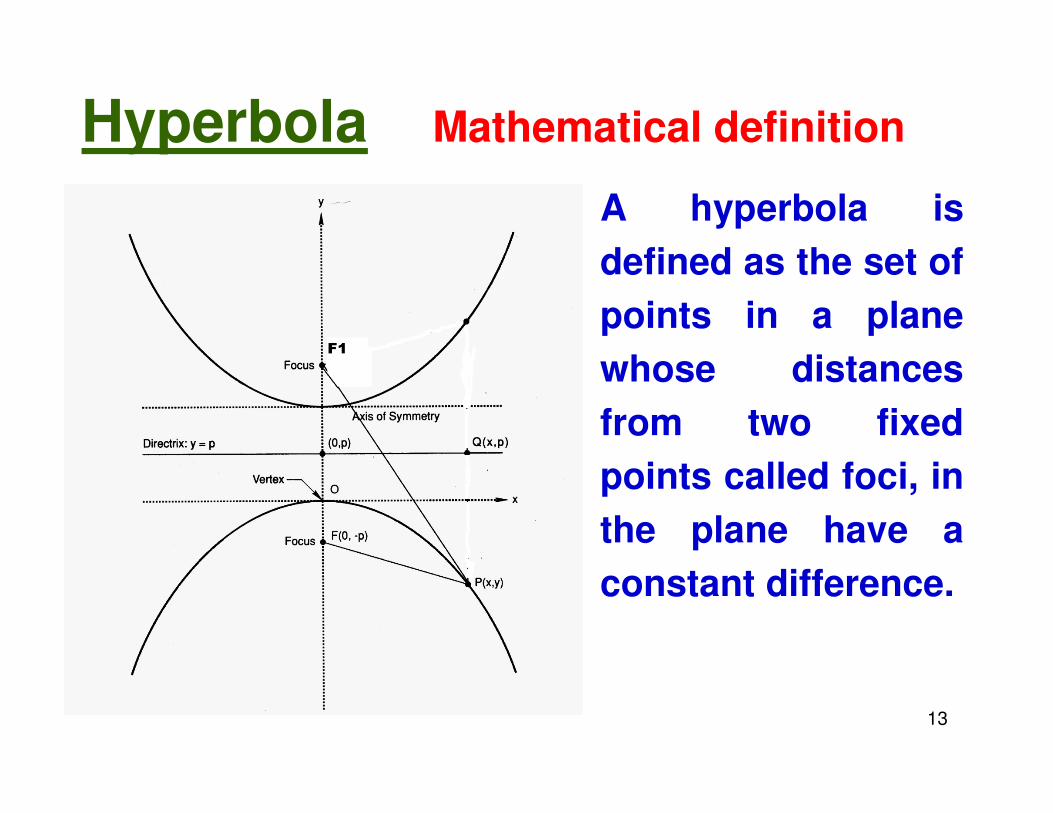
Hyperbola – Mathematical definition
A hyperbola isdefined as the set ofpoints in a planewhose distancesfrom two fixed
13
from two fixedpoints called foci, inthe plane have aconstant difference.

Constructing a Hyperbola
Draw the axis of symmetry andconstruct a perpendicular throughthe axis. Locate focal point Fequidistant from the perpendicularand on either side of it. Locatepoints A and B on the axisequidistant from the perpendicular.
AB is the distance between vertices
Given: Distance between Foci and Distance between vertices
14
With F as center and radius R1, anddraw the arcs. With R1 + AB, radius,and F as center, draw a second setof arcs. The intersection of the twoarcs on each side of theperpendicular are points on thehyperbola
Select a new radius R2 and repeatstep 2. Continue this process untilseveral points on the hyperbola aremarked

Roulettes
• Roulettes are curves generated by the rollingcontact of one curve or line on another curve orline, without slipping.
• There are various types of roulettes.
• The most common types of roulettes used inengineering practice are: Cycloids,Trochoids, and Involutes.

Cycloid
Generating circle
A Cycloid is generated by a point on the circumference of acircle rolling along a straight line without slipping
The rolling circle is called the Generating circleThe straight line is called the Directing line or Base line
Generating circle
Base line

Constructing a cycloid
� Generating circle has its center at C and has a radius of C-P’. Straight line PP’ isequal in length to the circumference of the circle and is tangent to the circle atpoint P’.
� Divide the circle into a number of equal segments, such as 12. Number theintersections of the radii and the circle.
� From each point of intersection on the circle, draw a construction line parallel to linePP’ and extending up to line P’C’.
� Divide the line CC’ into the same number of equal parts, and number them. Drawvertical lines from each point to intersect the extended horizontal centerline of thecircle. Label each point as C1, C2, C3, …. C12.
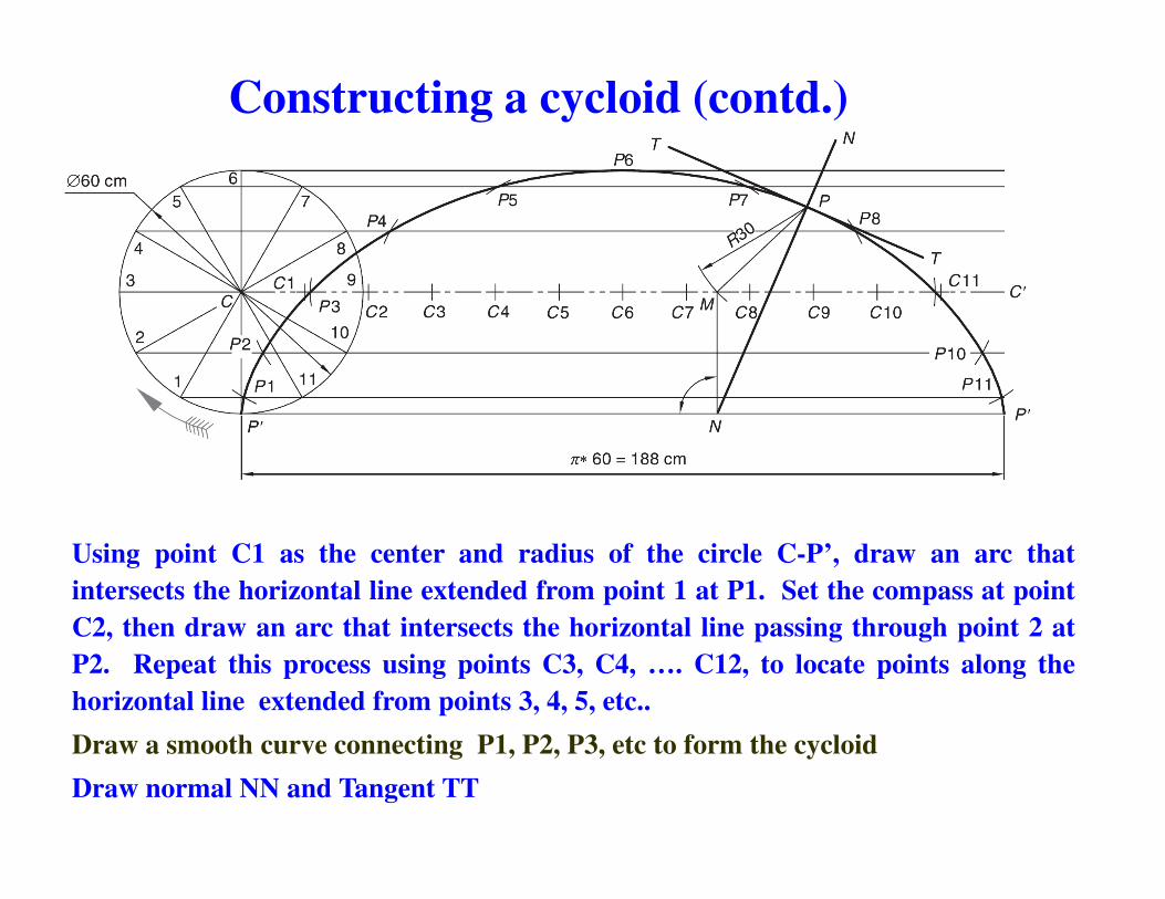
Constructing a cycloid (contd.)
Using point C1 as the center and radius of the circle C-P’, draw an arc thatintersects the horizontal line extended from point 1 at P1. Set the compass at pointC2, then draw an arc that intersects the horizontal line passing through point 2 atP2. Repeat this process using points C3, C4, …. C12, to locate points along thehorizontal line extended from points 3, 4, 5, etc..Draw a smooth curve connecting P1, P2, P3, etc to form the cycloidDraw normal NN and Tangent TT
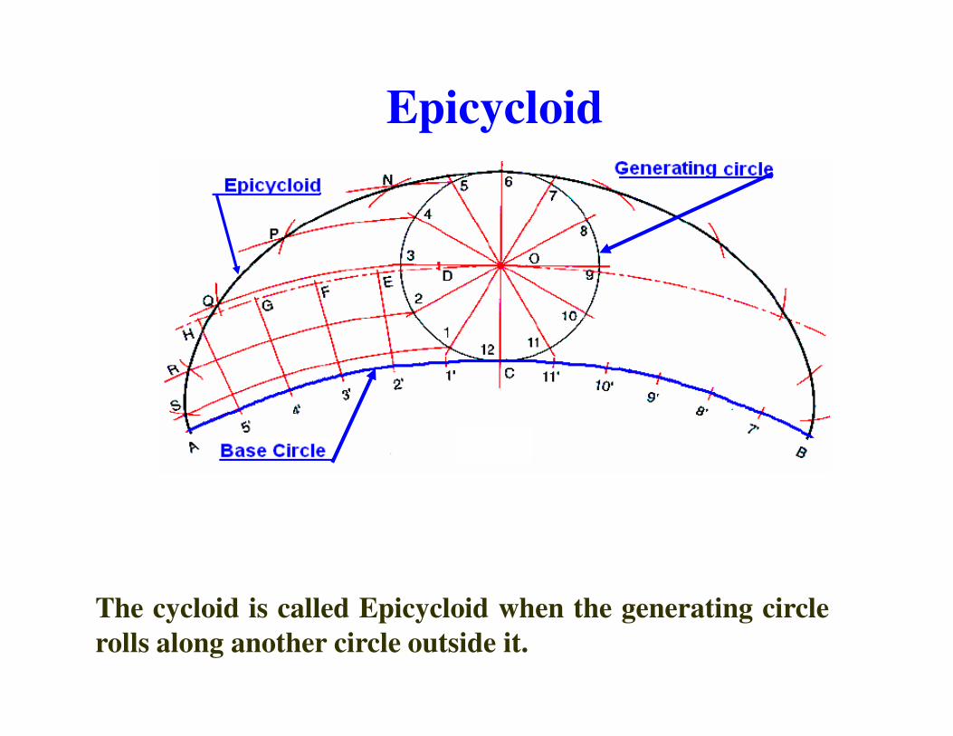
Epicycloid
The cycloid is called Epicycloid when the generating circlerolls along another circle outside it.

Constructing an Epicycloid
1) With O as centreand OC as radius,draw an arc torepresent locus ofcentre.centre.
2) Divide arc PQ into 12 equal partsand name them as1’, 2’, …., 12’.
3) Join O1’, O2’, … and produce them to cut the locus of centres at C1, C2, ….
4) Taking C1 as centre, and radius equal to 20 mm, draw an arc cutting the arc through 1 at P1. Similarly obtain points P2, P3,…., P12.
5) Join P1, P2….. With French curve

Hypocycloid
Hypocycloid is obtained when the generating circle rollsalong another circle inside it.
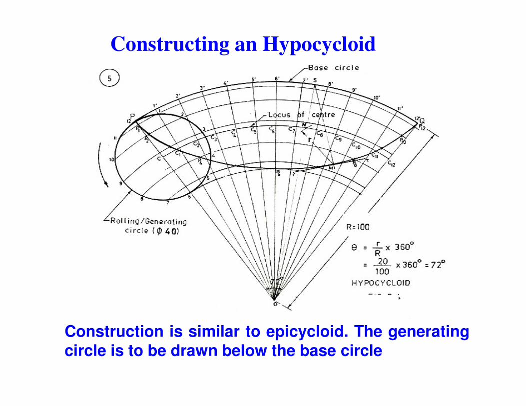
Constructing an Hypocycloid
Construction is similar to epicycloid. The generatingcircle is to be drawn below the base circle
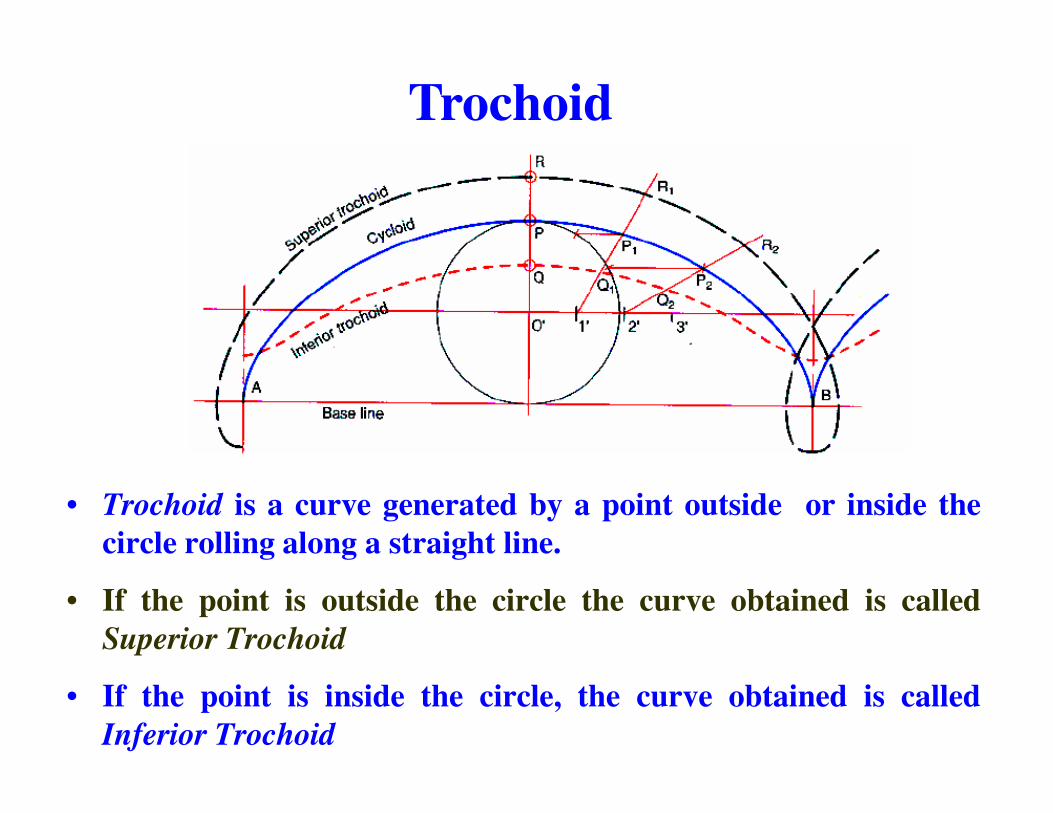
Trochoid
• Trochoid is a curve generated by a point outside or inside thecircle rolling along a straight line.
• If the point is outside the circle the curve obtained is calledSuperior Trochoid
• If the point is inside the circle, the curve obtained is calledInferior Trochoid

Classification of Cycloidal curves
Generating Circle
On the directing line
Outside the directing line
Inside the directing line
Generating
On the generating circle
Cycloid Epicycloid Hypocycloid
Generating point
circle
Outside the generating circle
Superior trochoid
Superior epitrochoid
Superior Hypotrochoid
Inside the generating circle
Inferior trochoid
Inferior epitrochoid
Inferior hypotrochoid

Involute
An Involute is a curve traced by the free end of a threadunwound from a circle or a polygon in such a way thatthe thread is always tight and tangential to the circle orside of the polygon

Construction of Involute of circleDraw the circle with c as centerand CP as radius.
Draw line PQ = 2ππππCP, tangent tothe circle at P
Divide the circle into 12 equal parts. Number them as 1, 2…
Divide the line PQ into 12 equal parts and number as 1�, 2�…..parts and number as 1�, 2�…..
Draw tangents to the circle at 1, 2,3….
Locate points P1, P2 such that 1-P1 = P1�, 2-P2 = P2�….
Join P, P1, P2….
The tangent to the circle at any point on it is always normal to the its involute.
Join CN. Draw a semicircle with CN as diameter, cutting the circle at M. MN is the normal.

ME 111: Engineering Drawing
Theory of Projections
27
Theory of Projections
Indian Institute of Technology GuwahatiGuwahati – 781039

Projection theoryProjection theory
3-D objects and structures are represented graphically on 2-D media.
All projection theory are based on two variables:
� Line of sight� Plane of projection.

Projection system

Plane of ProjectionPlane of Projection� A plane of projection (i.e, an image or picture
plane) is an imaginary flat plane upon which the image created by the line of sight is projected.
� The image is produced by connecting the points � The image is produced by connecting the points where the lines of sight pierce the projection plane. In effect, 3-D object is transformed into a 2-D representation, also called projections.
� The paper or computer screen on which a drawing is created is a plane of projection.
Projection Methods
Projection methods are very important techniques in engineering drawing.
Two projection methods used are: Two projection methods used are:
� Perspective and � Parallel.

In perspective projection, all lines of sight start at a single point.

In parallel projection, all lines of sight are parallel.

Parallel vs Perspective ProjectionParallel vs Perspective Projection
� Parallel projection� Distance from the observer to the object is infinite,
projection lines are parallel – object is positioned at infinity.
� Less realistic but easier to draw.
Χ Perspective projection� Distance from the observer to the object is finite and
the object is viewed from a single point – projectors are not parallel.
� Perspective projections mimic what the human eyes see, however, they are difficult to draw.


