

Technology Training that Workswww.idc-online.com/slideshare
Mechanical Design Concepts for
Non-Mechanical EngineersBy Steve Mackay

www.eit.edu.au Technology Training that Workswww.idc-online.com/slideshare
Overall Presentation
This workshop is designed for personnel with a need to understand the use, care,
installation, or the economics associated with mechanical machinery.
www.eit.edu.au Technology Training that Workswww.idc-online.com/slideshare
Objectives• The importance of
common engineering material properties in relation to component life and failure
• How to monitor, control and analyse vibrations

www.eit.edu.au Technology Training that Workswww.idc-online.com/slideshare
Topics
• Introduction• Mechanical Materials• Vibration• Conclusion

www.eit.edu.au Technology Training that Workswww.idc-online.com/slideshare
ENGINEERING MATERIALS

www.eit.edu.au Technology Training that Workswww.idc-online.com/slideshare
Tension and CompressionLoad, P
P
Area Ao
Lo
L/2
L/2
Load, P
P
Area Ao
Lo
L/2
L/2
tension compression
Axial force:
A load directed along the axis of
the object resulting in either
tension or compression

www.eit.edu.au Technology Training that Workswww.idc-online.com/slideshare
Stress and Strain• Stress may be defined as load/area.
• Strain is the deformation of the component/original length.
• A stress may be normal, shear, or torsion - leading to corresponding deformations.
• Stress cannot be measured directly, but deformation can be.

www.eit.edu.au Technology Training that Workswww.idc-online.com/slideshare
Normal Stress
0AP
Stress that acts in a direction perpendicular to the cross-sectional area.
Normal stress is the force per unit area and is given by:
Where
σ is the stress in N/m2
P is the instantaneous force applied perpendicular to the specimen cross- section in N
A0 is the original cross-section prior to deformation in m2.

www.eit.edu.au Technology Training that Workswww.idc-online.com/slideshare
Normal Stress
• An object in tension has resulting tensile stresses, and an object in compression has
resulting compressive stresses.

www.eit.edu.au Technology Training that Workswww.idc-online.com/slideshare
Elastic Deformation• Elastic deformation is a nonpermanent
deformation that is totally recovered upon release of the applied stress.
• Elastic region is linear for most metals.
• But for some materials like grey cast iron, concrete and many polymers, the elastic region is non-linear.

www.eit.edu.au Technology Training that Workswww.idc-online.com/slideshare
Elastic Deformation• If the elastic region is linear (or nearly linear) on
application of tensile stresses, Hooke’s Law is applied:
• Where E is the modulus of elasticity or Young’s Modulus (GPa).
• For most metals this typically ranges between 45 GPa and 407 GPa.
E

www.eit.edu.au Technology Training that Workswww.idc-online.com/slideshare
Stress-Strain Diagramelongation
0.2% offset yield stress
Sy
proportional limit
(ultimate)E
engineering strain (e = L/Lo)
engi
neer
ing
stre
ss (S
=P/A
o)
O
A
www.eit.edu.au Technology Training that Workswww.idc-online.com/slideshare
Stress-Strain Diagram
• Modulus of elasticity: - Slope of the linear region of the stress-strain
diagram.
• Proportional limit: - Stress at which the linear relationship between
stress and strain fails to exist.
www.eit.edu.au Technology Training that Workswww.idc-online.com/slideshare
Stress-Strain Diagram• Yield stress: - Stress at which yielding of the material takes place, i.e.
considerable elongation of the test specimen takes place with no noticeable increase in tensile force.
• Strain hardening: - Change in the crystalline structure of the material that
occurs during yielding, resulting in increased resistance of the material to further deformation.

www.eit.edu.au Technology Training that Workswww.idc-online.com/slideshare
Common Eng. Material Properties
• Stiffness:- Indication of how much a component deflects
under a given load.
• Resistance of material to elastic deformation under load is measured by Young’s Modulus (MPa).

www.eit.edu.au Technology Training that Workswww.idc-online.com/slideshare
Common Engg. Material Properties
• Stiffness (contd.):
• A stiff material (diamond) has high Young's modulus and changes shape only slightly under elastic load.
• A flexible material (rubber) has low Young's modulus and changes its shape considerably.

www.eit.edu.au Technology Training that Workswww.idc-online.com/slideshare
Common Engg. Material Properties
• Ductility:• Ability of a metal to plastically deform without
breaking or fracturing.
• This property allows a metal to be drawn into wires or filaments.
• Elongation and reduction of area are common indices of ductility.

www.eit.edu.au Technology Training that Workswww.idc-online.com/slideshare
Common Engg. Material Properties
• Toughness:- Resistance to fracture of a material, when
stressed.
- Can also be defined as the ability of a material to absorb energy.
- Key to toughness is a good combination of strength and ductility.

www.eit.edu.au Technology Training that Workswww.idc-online.com/slideshare
Common Engg. Material Properties
• Strength:• Ability of a material to resist deformation.
• Usually considered based on maximum load that can be borne before failure is apparent.
• The yield strength with a safety factor is usually used.

www.eit.edu.au Technology Training that Workswww.idc-online.com/slideshare
Common Engg. Material Properties• Hardness:• Resistance of a metal to plastic deformation, usually by
indentation.
• May also refer to resistance to scratching, abrasion, or cutting.
• Property of a metal which gives it the ability to resist being permanently deformed (bent, broken, or have its shape changed), when a load is applied.
• Greater the hardness, greater is the resistance to deformation

www.eit.edu.au Technology Training that Workswww.idc-online.com/slideshare
»Fracture
»Fatigue
»Creep
»Rupture
»Corrosion
Typical failure mechanisms

www.eit.edu.au Technology Training that Workswww.idc-online.com/slideshare
Fracture
• Separation of a body into two or more pieces
- in response to an imposed stress that is static (i.e. constant or slowly changing with time)
- at temperatures that are low relative to the melting temperature of the material.
www.eit.edu.au Technology Training that Workswww.idc-online.com/slideshare
Fracture• The applied static stress may be- Tensile- Compressive- Shear - Torsional
• Fracture involves two steps in response to imposed stress:- crack formation - crack propagation

www.eit.edu.au Technology Training that Workswww.idc-online.com/slideshare
Fracture• Two possible fracture modes:
- ductile fracture - brittle fracture
• Mode of fracture is dependent on crack propagation.

www.eit.edu.au Technology Training that Workswww.idc-online.com/slideshare
Fracture Profiles• A - Highly ductile fracture
in which the specimen necks down to a point.
• B - Moderately ductile fracture after necking.
• C - Brittle fracture without any plastic deformation.
A B C

www.eit.edu.au Technology Training that Workswww.idc-online.com/slideshare
Ductile Fracture• Extensive plastic deformation in the vicinity of an
advancing crack.
• Relatively slow crack propagation.
• Crack is stable, i.e. resists further extension unless there is an increase in the applied stress.
• Plastic deformation gives warning of imminent fracture.

www.eit.edu.au Technology Training that Workswww.idc-online.com/slideshare
Brittle Fracture• Very little appreciable deformation at the fracture
surface.
• Rapid crack propagation. • Unstable crack, i.e. crack propagation once started will
continue without an increase in magnitude of the applied stress.
• Sudden and catastrophic.

www.eit.edu.au Technology Training that Workswww.idc-online.com/slideshare
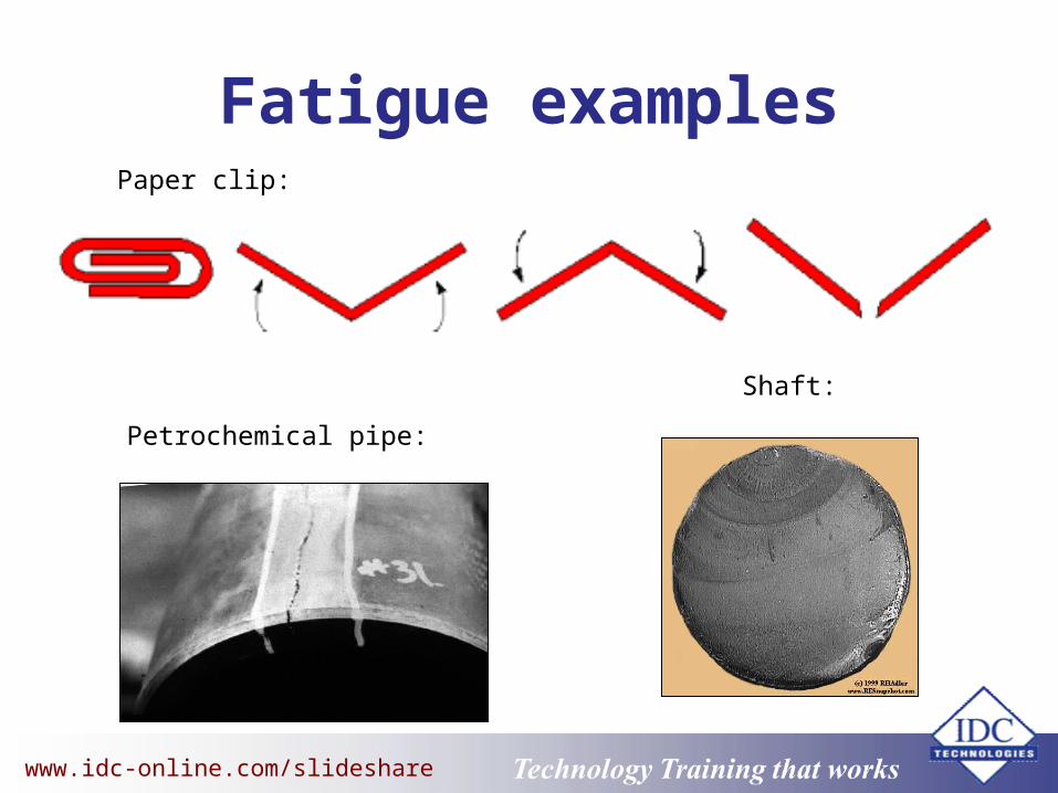
Fatigue• Form of failure that occurs in structures subjected to
- Dynamic
- Fluctuating stresses
• Examples: bridges, aircraft, and machine components.
www.eit.edu.au Technology Training that Workswww.idc-online.com/slideshare
Fatigue examplesPaper clip:
Petrochemical pipe:
Shaft:

www.eit.edu.au Technology Training that Workswww.idc-online.com/slideshare
Fatigue examples

www.eit.edu.au Technology Training that Workswww.idc-online.com/slideshare
Interesting history
In World War II, the USA built 2708 “Liberty Ships” which were all-welded.
1031 failed due to brittle fracture of welded joints. More than 200 sunk. Most expensive experiment of century. Cause
steel becomes more brittle at low temperatures. stress concentration at weld.

www.eit.edu.au Technology Training that Workswww.idc-online.com/slideshare
Interesting history

www.eit.edu.au Technology Training that Workswww.idc-online.com/slideshare
Interesting history

www.eit.edu.au Technology Training that Workswww.idc-online.com/slideshare
Type of fracture?
A) ductile fracture B) brittle fracture

www.eit.edu.au Technology Training that Workswww.idc-online.com/slideshare
Type of fracture?
A) ductile fracture B) brittle fracture

www.eit.edu.au Technology Training that Workswww.idc-online.com/slideshare
Common Engg. Material Properties
• Creep strength
• Ability of a metal to resist slow deformation due to stress.
• Material type, stress, temp.& environment determine its nature.

www.eit.edu.au Technology Training that Workswww.idc-online.com/slideshare
Creep• Time-dependent permanent deformation that
occurs under stress.
• For most metals, it is important only at elevated temperatures.
• Boilers, gas turbines & ovens are examples of systems having components that experience creep.

www.eit.edu.au Technology Training that Workswww.idc-online.com/slideshare
Creep• Failures are usually easy to identify due to the
deformation that occurs.
• Failures may appear ductile or brittle.
• Creep testing is done at constant temperature and constant load.
• However, actual components may experience damage at various temp. and loading conditions.

www.eit.edu.au Technology Training that Workswww.idc-online.com/slideshare
Common Engg. Material Properties
• Corrosion:
– Process by which the metal is subjected to degradation &
– subsequent deterioration in metal properties as a result of
– chemical & electrical reaction with other materials.

www.eit.edu.au Technology Training that Workswww.idc-online.com/slideshare
Corrosion• Caused by the flow of electrons from one metal to
another or
• from one part of the surface of one metal to another part of the surface of the same metal.
Two basic types:
1. Uniform corrosion2. Localised corrosion

www.eit.edu.au Technology Training that Workswww.idc-online.com/slideshare
General Corrosion• Electrochemical reactions occur at approximately the
same rate over the entire surface.
• Uniform rate of metal thickness loss over the surface.
• Parameters affecting general corrosion:- low pH, dissolved oxygen, dissolved carbon dioxide, high
temperature

www.eit.edu.au Technology Training that Workswww.idc-online.com/slideshare
General Corrosion
www.eit.edu.au Technology Training that Workswww.idc-online.com/slideshare
Localized Corrosion• Selective attack at heterogeneous site of the metal.
• Non-uniform metal thickness loss over the surface.
• Parameters affecting localized corrosion –
- environment (CO2, CCl-, pH, flow rate), material (segregation, inclusions, different phases, grain boundaries), stress (static/fluctuating)

www.eit.edu.au Technology Training that Workswww.idc-online.com/slideshare
Localized Corrosion

www.eit.edu.au Technology Training that Workswww.idc-online.com/slideshare
Localized Corrosion

www.eit.edu.au Technology Training that Workswww.idc-online.com/slideshare
Galvanic Corrosion
Galvanic corrosion is an electrochemical action of two dissimilar metals in the presence of an electrolyte and an electron conductive path. It occurs when dissimilar metals are in contact.

www.eit.edu.au Technology Training that Workswww.idc-online.com/slideshare
Crevice CorrosionCrevice or contact corrosion is the corrosion produced at the region of contact of metals with metals or metals with nonmetals. It may occur at washers, under barnacles, at sand grains, under applied protective films, and at pockets formed by threaded joints.

www.eit.edu.au Technology Training that Workswww.idc-online.com/slideshare
Stress Corrosion
Stress corrosion cracking (SCC) is caused by the simultaneous effects of tensile stress and a specific corrosive environment. Stresses may be due to applied loads, residual stresses from the manufacturing process, or a combination of both.

www.eit.edu.au Technology Training that Workswww.idc-online.com/slideshare
Fatigue Corrosion
Corrosion fatigue is a special case of stress corrosion caused by the combined effects of cyclic stress and corrosion. No metal is immune from some reduction of its resistance to cyclic stressing if the metal is in a corrosive environment.

www.eit.edu.au Technology Training that Workswww.idc-online.com/slideshare
Concrete Corrosion
Concrete is a widely-used structural material that is frequently reinforced with carbon steel reinforcing rods, post-tensioning cable or prestressing wires. The steel is necessary to maintain the strength of the structure, but it is subject to corrosion.

www.eit.edu.au Technology Training that Workswww.idc-online.com/slideshare
Mechanical Vibrations

www.eit.edu.au Technology Training that Workswww.idc-online.com/slideshare
• Single degree of freedom system• Terminologies: Amplitude, phase and frequency• Natural frequency of vibration• Multiple degree of freedom system• Vibration measurement: Sensors, analyzers and interpretation• Use of vibration as a condition monitoring tool

www.eit.edu.au Technology Training that Workswww.idc-online.com/slideshare
Vibration • Vibration is the displacement of mass back and forth from its
static position during a motion of any machine or its part.
• If all the parts of the body move together in the same direction at any point in time, it is called rigid body motion (hence not vibration).

www.eit.edu.au Technology Training that Workswww.idc-online.com/slideshare
Single degree of freedom

www.eit.edu.au Technology Training that Workswww.idc-online.com/slideshare
Three Fundamental Properties of a Machine
• Mass (M)• • Stiffness (k)
• Damping (C)

www.eit.edu.au Technology Training that Workswww.idc-online.com/slideshare
Mass
• Mass is a measure of inertia of the body, which has a tendency to remain in its state of rest of motion unless an external force is applied to alter the state of the body at rest, or change the speed or direction of a moving body.
• The unit of mass is kilogram.

www.eit.edu.au Technology Training that Workswww.idc-online.com/slideshare
Stiffness
• Stiffness can be termed as the ability of a body or structure to resist any deformation.
• It is defined as the ratio of constant force applied on a body to the displacement produced by it.
• The unit for measuring the stiffness is N/m.

www.eit.edu.au Technology Training that Workswww.idc-online.com/slideshare
Damping
• When a machine part is set to vibrate, the velocity of the part tends to reduce under the effect of friction. Unless the force is supplied during each cycle, the velocity falls off at each successive oscillation damping.
• The unit for measuring damping is N/(m/s).

www.eit.edu.au Technology Training that Workswww.idc-online.com/slideshare
Three Fundamental Properties of a Machine (contd)
• All machines exhibit the three fundamental properties that determine how the machine or part responds to forces that cause vibrations.
• These properties may help reduce the vibration of a machine when it tends to vibrate excessively.

www.eit.edu.au Technology Training that Workswww.idc-online.com/slideshare
Terminology Describing Vibration
• Frequency
• Maximum deflection or amplitude
• Phase
www.eit.edu.au Technology Training that Workswww.idc-online.com/slideshare
Frequency
• Frequency is denoted by the number of cycles passing any point in a medium per second.
• Frequency of the sine curve is the reciprocal of the curve’s period.
• Frequency is measured in Hertz (Hz).

www.eit.edu.au Technology Training that Workswww.idc-online.com/slideshare
Maximum Deflection or Amplitude
• The maximum displacement of the vibrating particle from the mean position is known as amplitude.
• The amplitude of a wave gives a relative indication of the amount of energy the wave transmits.
• Amplitude can be described in terms of the maximum, or the root mean square (rms).

www.eit.edu.au Technology Training that Workswww.idc-online.com/slideshare
Amplitude Description

www.eit.edu.au Technology Training that Workswww.idc-online.com/slideshare
Phase
• Phase is described in terms of angle or fraction of time period elapsed since the particle left the mean position in the positive direction of the motion.

www.eit.edu.au Technology Training that Workswww.idc-online.com/slideshare
Forcing Frequency
• Forcing frequencies: Produced as different events take place in a piece of machinery while its shaft completes one revolution.
• They occur when the machinery is operating, and change in magnitude in proportion to the speed of the machinery.

www.eit.edu.au Technology Training that Workswww.idc-online.com/slideshare
Rotational Frequency
• Rotational frequencies are caused due to residual unbalance, which causes a shift in the centre of gravity from the geometric centre of the shaft.
• This unbalance force is proportional to the momentum caused by the unbalanced mass and the square of the speed.

www.eit.edu.au Technology Training that Workswww.idc-online.com/slideshare
Natural Frequency
• Natural frequency: Also known as free vibration of a mechanical structure, which continues to oscillate even after excitation force is removed.
• Oscillation stops gradually due to damping in the system.
• The natural frequencies are inherent to the structure due to its mass, stiffness and damping properties.

www.eit.edu.au Technology Training that Workswww.idc-online.com/slideshare
Natural Frequency (contd..)
• Natural frequency depends on mass, stiffness and damping of the machinery - not on operational conditions!
• Equation given below represents the relation between natural frequency and stiffness and mass of the structure when there is no damping.
• where:• Fn = natural frequency [Hz]• k = the stiffness of the spring [N/m]• M = mass [kg]
• Natural frequency of a system is usually expressed in Hertz [Hz].
12n
kFM

www.eit.edu.au Technology Training that Workswww.idc-online.com/slideshare
Multiple degree of freedom

www.eit.edu.au Technology Training that Workswww.idc-online.com/slideshare
Vibration Measurement Sensor / transducer • Converts one energy type (vibration) into
another (voltage / electric current)
• Measures machinery / structural vibrations
• Includes velocity pickups, accelerometers, proximity probes

www.eit.edu.au Technology Training that Workswww.idc-online.com/slideshare
Vibration Measurement• Accelerometers• Most commonly used • Light, compact and
quite rugged while also possessing a wide frequency range.
www.eit.edu.au Technology Training that Workswww.idc-online.com/slideshare
Vibration Measurement• Accelerometers utilize piezoelectric principle to
convert mechanical motion into a voltage signal proportional to acceleration of the vibration.
• Consist of a piezoelectric crystal made of ferroelectric materials and a small mass enclosed in a protective metal case.

www.eit.edu.au Technology Training that Workswww.idc-online.com/slideshare
Accelerometers

www.eit.edu.au Technology Training that Workswww.idc-online.com/slideshare
Vibration Measurement
Which to choose:• Vibration severity: Measure of displacement, velocity
or acceleration characteristics of vibration.
• Can look at spectrum or overall vibration.
• Greater vibration amplitudes generally correspond to higher level of machinery faults.

www.eit.edu.au Technology Training that Workswww.idc-online.com/slideshare
Vibration Measurement• Frequencies below 10 Hz: Vibration levels for
displacement large.
• Acceleration yields significant values in high frequency range (1000 - 20 000 Hz) choose acceleration.
• Severity of vibration best indicated by velocity in frequency range 10 -1000Hz.

www.eit.edu.au Technology Training that Workswww.idc-online.com/slideshare
Vibration Measurement• Sensor Mounting
Precautions• Measurement surface
should be sufficiently stiff to resist pressure exerted by the probe.
• Measure motion along major axes - V H A
dry endwet end
pump
y
xz
y
xz
axial - x
verti
cal -
y
shaft

www.eit.edu.au Technology Training that Workswww.idc-online.com/slideshare
Sensor mounting

www.eit.edu.au Technology Training that Workswww.idc-online.com/slideshare
Sensor mounting

www.eit.edu.au Technology Training that Workswww.idc-online.com/slideshare
Sensor mounting

www.eit.edu.au Technology Training that Workswww.idc-online.com/slideshare
Vibration Measurement
• Spectrum Analyzers• Electronic devices that convert
the time waveform of a given signal into its frequency components.
• Possible to show on-line vibration spectra, overall vibration levels, phase, balancing information, etc.

www.eit.edu.au Technology Training that Workswww.idc-online.com/slideshare
Vibration Measurement• Two-channel
Analyzer• Collect, record and
display vibration-related characteristics such as FFT spectra, trend plots and time domain waveforms.
www.eit.edu.au Technology Training that Workswww.idc-online.com/slideshare
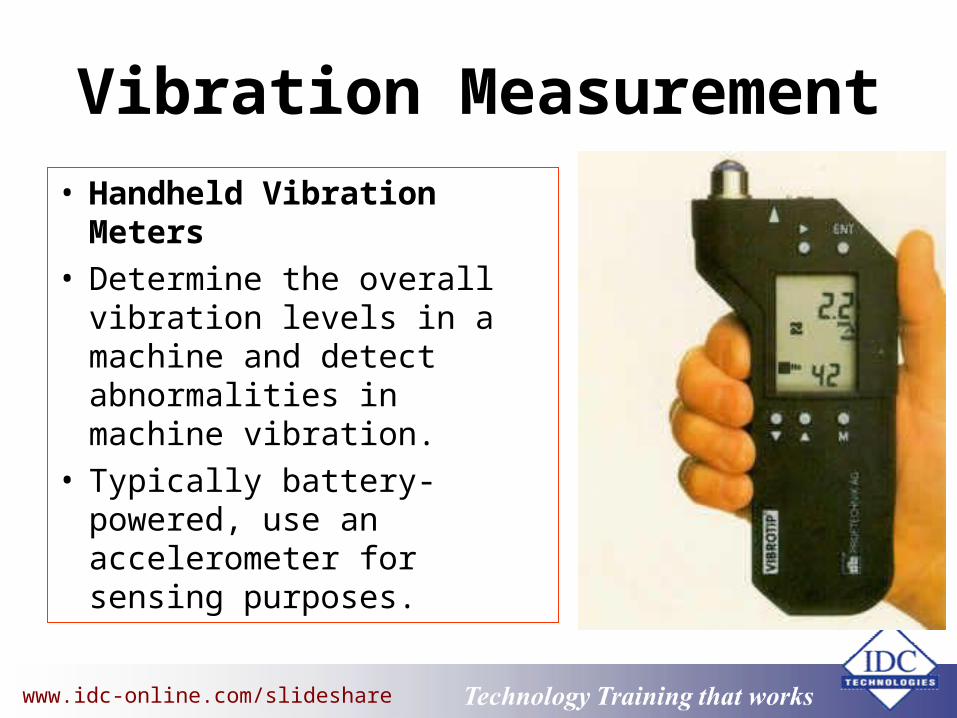
Vibration Measurement• Handheld Vibration Meters• Determine the overall
vibration levels in a machine and detect abnormalities in machine vibration.
• Typically battery-powered, use an accelerometer for sensing purposes.

www.eit.edu.au Technology Training that Workswww.idc-online.com/slideshare
Machinery Fault Detection

www.eit.edu.au Technology Training that Workswww.idc-online.com/slideshare
Reasons for Defects that Cause High Vibrations in Machines
• Unbalance of rotating parts Machining errors Rotor eccentricity Uneven mass distribution in electric motor rotor windings Missing balance weights Bowed shafts Lack of homogeneity in cast parts Uneven dirt accumulation in cast parts
• Misalignment of couplings or bearings Faulty assembly of subassembly parts of motors and pumps Shifting of the relative position of components after assembly Distortion due to forces exerted by piping Distortion of flexible supports due to torque Temperature induced growth of machine structure Coupling face not perpendicular to the shaft axis

www.eit.edu.au Technology Training that Workswww.idc-online.com/slideshare
Reasons for Defects that Cause High Vibrations in Machines (contd)
• Bent shafts • Journal Bearings:
oil whip, oil whirl, looseness of the journal or journal thrust bearings (all of these mostly occurs at a low frequency levels)
• Rolling element Bearings: improper lubrication, improper mounting, misalignment, overloading
and other manufacturing defects
• Mechanical looseness: rotational and non-rotational looseness
• Electrically induced vibration: slip related vibration, slot pass frequency or shorted laminations

www.eit.edu.au Technology Training that Workswww.idc-online.com/slideshare
Reasons for Defects that Cause High Vibrations in Machines (contd)
• Others: Combustion noise in turbines Suction pressure, discharge pressure and cavitation will affect the vibration
signature. Uneven build-up of waste particles in axial or centrifugal fans Damaged or eroded vanes of centrifugal compressors Drive belt defects such as:
mismatched, worn or overstretched belts eccentric or misaligned sheaves or sheave run-outs in belts Belt resonance
Defects in gearboxes such as Gear hunting Machining errors of the teeth Damaged gear teeth Eccentric gears and bent shafts

www.eit.edu.au Technology Training that Workswww.idc-online.com/slideshare
Vibration as a condition monitoring tool
• Frequency analysis is also known as spectrum analysis.
• Frequency analysis is done by transforming the information in the signal from the time domain into the frequency domain.
• Frequency analysis is usually performed when the time domain waveform cannot clearly represent the spectrum.

www.eit.edu.au Technology Training that Workswww.idc-online.com/slideshare
A Typical Mechanical System

www.eit.edu.au Technology Training that Workswww.idc-online.com/slideshare
A Typical Mechanical System
Motor frequency = 1800/60 rpm = 30 HzPump frequency = 50/150 x 1800 rpm
= 600 rpm = 10 HzGear mesh frequency = 50 teeth x 1800 rpm= 150 teeth x 600 rpm= 90 000 rpm= 1500 HzBlade frequency = 8 vanes x 600 rpm= 4800 rpm= 80 Hz

www.eit.edu.au Technology Training that Workswww.idc-online.com/slideshare
Unbalance - Static
• Amplitude due to unbalance will vary with the square of speed.
• The FFT will show 1 rpm frequency of vibration.
• It will be predominant.• Phase difference is as
shown.

www.eit.edu.au Technology Training that Workswww.idc-online.com/slideshare
Unbalance Static Static

www.eit.edu.au Technology Training that Workswww.idc-online.com/slideshare
Parallel Misalignment

www.eit.edu.au Technology Training that Workswww.idc-online.com/slideshare
• The predominant peak is at 2.
• Vibrations in radial direction are higher than in the axial direction.
Parallel Misalignment

www.eit.edu.au Technology Training that Workswww.idc-online.com/slideshare
Thank You For Your Interest
If you are interested in further training, please visit:
IDC Technologies Short Courses:Two-day practical courses available to the public:
http://www.idc-online.com/slideshare


