
ARCH 631 Note Set 2.2 F2015abn
61
Mechanics of Materials Primer
Notation:
A = area (net = with holes, bearing = in
contact, etc...)
b = total width of material at a
horizontal section
d = diameter of a hole
D = symbol for diameter
E = modulus of elasticity or Young’s
modulus
f = symbol for stress
fallowable = allowable stress
fcritical = critical buckling stress in column
calculations from Pcritical
fv = shear stress
fp = bearing stress (see P)
Fallowed = allowable stress (used by codes)
Fconnector = shear force capacity per
connector
I = moment of inertia with respect to
neutral axis bending
J = polar moment of inertia
K = effective length factor for columns
L = length
Le = effective length that can buckle for
column design, as is e� , Leffective
M = internal bending moment, as is M’
n = number of connectors across a joint
p = pitch of connector spacing
P = name for axial force vector, as is P’
Pcrit = critical buckling load in column
calculations, as is Pcritical, Pcr
Q = first moment area about a neutral
axis
Qconnected = first moment area about a neutral
axis for the connected part
r = radius of gyration or radius of a
hole
S = section modulus
t = thickness of a hole or member
T = name for axial moment or torque
V = internal shear force
y = vertical distance
α = coefficient of thermal expansion for
a material
δ = elongation or length change
Tδ = elongation due or length change
due to temperature
ε = strain
εT = thermal strain (no units)
φ = angle of twist
γ = shear strain
π = pi (3.1415 radians or 180°)
θ = angle of principle stress
= slope of the beam deflection curve
ρ = name for radial distance
σ = engineering symbol for normal
stress
τ = engineering symbol for shearing
stress
∆ = displacement due to bending
T∆ = change in temperature
∫ = symbol for integration
Mechanics of Materials is a basic engineering science that deals with the relation between
externally applied load and its effect on deformable bodies. The main purpose of Mechanics of
Materials is to answer the question of which requirements have to be met to assure STRENGTH,
RIGIDITY, AND STABILITY of engineering structures.

ARCH 631 Note Set 2.2 F2015abn
62
Normal Stress
Stress that acts along an axis of a member; can be internal or external; can be compressive or
tensile.
netA
Pf == σ Strength condition: allowedallowable
net
ForfA
Pf <=
Shear Stress (non beam)
Stress that acts perpendicular to an axis or length of a member, or parallel to the cross section is
called shear stress.
Shear stress cannot be assumed to be uniform, so we refer to average shearing stress.
net
vA
Pf == τ Strength condition: allowedallowable
net
v ForA
Pf τ<=
Bearing Stress
A compressive normal stress acting between two bodies. bearing
pA
Pf =
Torsional Stress
A shear stress caused by torsion (moment around the axis). J
Tf v
ρ=
Bolt Shear Stress
Single shear - forces cause only one shear “drop” across the bolt. boltA
Pf
1=
Double shear - forces cause two shear changes across the bolt. boltA
Pf
2=
Bearing of a bolt on a bolt hole – The bearing surface can be represented by projecting the cross
section of the bolt hole on a plane (into a rectangle).
Bending Stress
A normal stress caused by bending; can be compressive or tensile. The stress
at the neutral surface or neutral axis, which is the plane at the centroid of the
cross section is zero.
S
M
I
Myfb ==
td
P
A
Pf p ==

ARCH 631 Note Set 2.2 F2015abn
63
pI
VQnF
areaconnected
connector ⋅≥
Beam Shear Stress
avevf − = 0 on the beam’s surface. Even if Q is a maximum at y = 0, we
don’t know that the thickness is a minimum there.
Rectangular Sections
maxvf − occurs at the neutral axis:
Webs of Beams
In steel W or S sections the thickness varies from the flange to the web. We neglect the shear
stress in the flanges and consider the shear stress in the web to be constant:
Connectors in Bending
Typical connections needing to resist shear are plates with nails or rivets or bolts in composite
sections or splices. The pitch (spacing) can be determined by the capacity in shear of the
connector(s) to the shear flow over the spacing interval, p.
where
p = pitch length
n = number of connectors connecting the connected area to the rest of the cross section
F = force capacity in one connector
Qconnected area = Aconnected area × yconnected area
yconnected area = distance from the centroid of the connected area to the neutral axis
Normal Strain
In an axially loaded member, normal strain, ε is the change in the length, δ with respect to the
original length, L.
xb
V
A
Vf v
∆⋅=
∆=
Ib
VQf avev =−
A
V
Ib
VQf v
2
3==
web
maxvA
V
A
Vf ≈=−
2
3
I
VQ
p
V allongitudin=
L
δε =

ARCH 631 Note Set 2.2 F2015abn
64
Shearing Strain
In a member loaded with shear forces, shear
strain, γ is the change in the sheared side, δs
with respect to the original height, L. For
small angles: φφ ≅tan .
In a member subjected to twisting, the shearing strain is a measure of the angle of twist with
respect to the length and distance from the center, ρ:
Stress vs. Strain
Behavior of materials can be measured by
recording deformation with respect to the
size of the load. For members with constant
cross section area, we can plot stress vs.
strain.
BRITTLE MATERIALS - ceramics, glass,
stone, cast iron; show abrupt fracture at
small strains.
DUCTILE MATERIALS – plastics, steel;
show a yield point and large strains
(considered plastic) and “necking” (give
warning of failure)
SEMI-BRITTLE MATERIALS – concrete;
show no real yield point, small strains, but have some “strain-hardening”.
Linear-Elastic Behavior
In the straight portion of the stress-strain diagram, the materials are elastic, which means if they
are loaded and unloaded no permanent deformation occurs.
True Stress & Engineering Stress
True stress takes into account that the area of the cross section changes with loading.
Engineering stress uses the original area of the cross section.
Hooke’s Law – Modulus of Elasticity
In the linear-elastic range, the slope of the stress-strain diagram is
constant, and has a value of E, called Modulus of
Elasticity or Young’s Modulus.
ARCH 631 Note Set 2.2 F2015abn
65
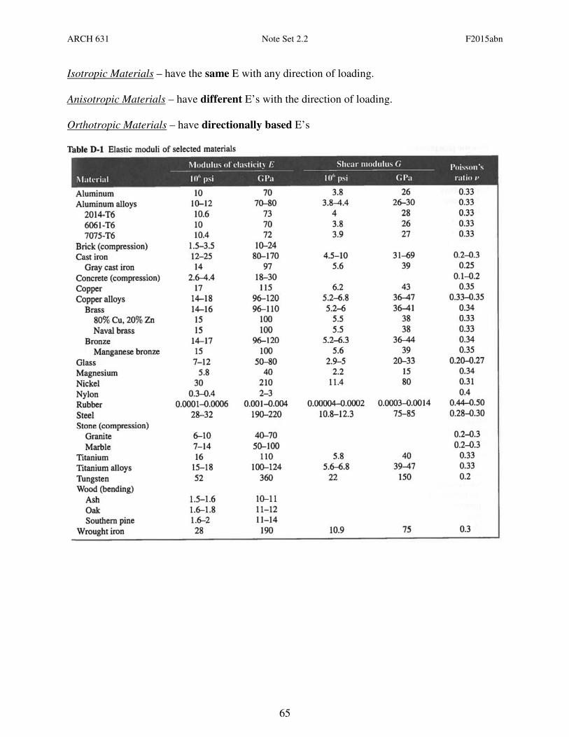
Isotropic Materials – have the same E with any direction of loading.
Anisotropic Materials – have different E’s with the direction of loading.
Orthotropic Materials – have directionally based E’s

ARCH 631 Note Set 2.2 F2015abn
66
Plastic Behavior & Fatigue
Permanent deformations happen outside the
linear-elastic range and are called plastic
deformations. Fatigue is damage caused by
reversal of loading.
• The proportional limit (at the end of the
elastic range) is the greatest stress valid
using Hooke’s law.
• The elastic limit is the maximum stress
that can be applied before permanent
deformation would appear upon
unloading.
• The yield point (at the yield stress) is where a ductile material continues to elongate without
an increase of load. (May not be well defined on the stress-strain plot.)
• The ultimate strength is the largest stress a material will see before rupturing, also called the
tensile strength.
• The rupture strength is the stress at the point of rupture or failure. It may not coincide with
the ultimate strength in ductile materials. In brittle materials, it will be the same as the
ultimate strength.
• The fatigue strength is the stress at failure when a member is subjected to reverse cycles of
stress (up & down or compression & tension). This can happen at much lower values than
the ultimate strength of a material.
• Toughness of a material is how much work (a combination of stress and strain) us used for
fracture. It is the area under the stress-strain curve.
Concrete does not respond well to tension and is tested in compression. The strength at crushing
is called the compression strength.
Materials that have time dependent elongations when loaded are said to have creep. Concrete
and wood creep. Concrete also has the property of shrinking over time.

ARCH 631 Note Set 2.2 F2015abn
67
Poisson’s Ratio
For an isometric material that is homogeneous, the properties are the
same for the cross section:
There exists a linear relationship while in the linear-elastic range of
the material between longitudinal strain and lateral strain:
Positive strain results from an increase in length with respect to overall length.
Negative strain results from a decrease in length with respect to overall length.
µ is the Poisson’s ratio and has a value between 0 and ½, depending on the material
Relation of Stress to Strain
;A
Pf =
L
δε = and
ε
fE = so
L
AP
Eδ
= which rearranges to: AE
PL=δ
Stress Concentrations
In some sudden changes of cross section, the stress concentration changes (and is why we used
average normal stress). Examples are sharp notches, or holes or corners.
Plane of Maximum Stress
When both normal stress and shear
stress occur in a structural member, the
maximum stresses can occur at some
other planes (angle of θ).
Maximum Normal Stress happens at °= 0θ AND
Maximum Shearing Stress happens at °= 45θ with only normal stress in the x direction.
E
f xzy
µεε −==
zy εε =
x
z
x
y
strainaxial
strainlateral
ε
ε
ε
εµ −=−=−=
y
z
x
ARCH 631 Note Set 2.2 F2015abn
68
Thermal Strains
Physical restraints limit deformations to be the same, or sum to zero, or be proportional with
respect to the rotation of a rigid body.
We know axial stress relates to axial strain: which relates δ to P
Deformations can be caused by the material reacting to a change in energy with temperature. In
general (there are some exceptions):
• Solid materials can contract with a decrease in temperature.
• Solid materials can expand with an increase in temperature.
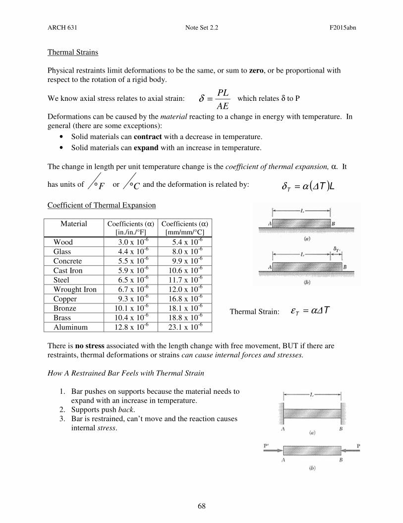
The change in length per unit temperature change is the coefficient of thermal expansion, α. It
has units of F° or C° and the deformation is related by:
Coefficient of Thermal Expansion
Material Coefficients (α)
[in./in./°F]
Coefficients (α)
[mm/mm/°C]
Wood 3.0 x 10⁻⁶
5.4 x 10⁻⁶
Glass 4.4 x 10⁻⁶
8.0 x 10⁻⁶
Concrete 5.5 x 10⁻⁶
9.9 x 10⁻⁶
Cast Iron 5.9 x 10⁻⁶
10.6 x 10⁻⁶
Steel 6.5 x 10⁻⁶
11.7 x 10⁻⁶
Wrought Iron 6.7 x 10⁻⁶
12.0 x 10⁻⁶
Copper 9.3 x 10⁻⁶
16.8 x 10⁻⁶
Bronze 10.1 x 10⁻⁶
18.1 x 10⁻⁶
Brass 10.4 x 10⁻⁶
18.8 x 10⁻⁶
Aluminum 12.8 x 10⁻⁶
23.1 x 10⁻⁶
There is no stress associated with the length change with free movement, BUT if there are
restraints, thermal deformations or strains can cause internal forces and stresses.
How A Restrained Bar Feels with Thermal Strain
1. Bar pushes on supports because the material needs to
expand with an increase in temperature.
2. Supports push back.
3. Bar is restrained, can’t move and the reaction causes
internal stress.
AE
PL=δ
( )LTT ∆αδ =
Thermal Strain: TT ∆αε =

ARCH 631 Note Set 2.2 F2015abn
69
Superposition Method
If we want to solve a statically indeterminate problem that has extra support forces:
• We can remove a support or supports that makes the problem look statically determinate
• Replace it with a reaction and treat it like it is an applied force
• Impose geometry restrictions that the support imposes
Beam Deflections
If the bending moment changes, M(x) across a beam of constant material and cross section then
the curvature will change:
The slope of the n.a. of a beam, θ, will be tangent to the radius of curvature, R:
The equation for deflection, y, along a beam is:
Elastic curve equations can be found in handbooks, textbooks, design manuals, etc...Computer
programs can be used as well.
Elastic curve equations can be superpositioned ONLY if the stresses are in the elastic range.
Column Buckling
Stability is the ability of the structure to support a specified load without undergoing
unacceptable (or sudden) deformations. A column loaded centrically can experience unstable
equilibrium, called buckling, because of how tall and slender they are. This instability is sudden
and not good.
Buckling can occur in sheets (like my “memory metal” cookie sheet), pressure vessels or slender
(narrow) beams not braced laterally.
The critical axial load to cause buckling is related to the deflected
shape we could get (or determine from bending moment of P·∆) as a
function of the end conditions.
Swiss mathematician Euler determined the relationship between the
critical buckling load, the material, section and effective length (as
long as the material stays in the elastic range):
( )2
min
2
L
EIPcritical
π= or
( ) 2
2
2
2
==
rL
EAπ
L
EIπP
ee
cr
dxxMEI
slope ∫== )(1
θ
∫∫∫ === dx)x(MEI
dxEI
y11
θ∆

ARCH 631 Note Set 2.2 F2015abn
70
and the critical stress (if less than the normal stress) is:
( ) 2
2
2
22
===
rL
E
LA
EAr
A
Pf
ee
criticalcritical
ππ
where I=Ar2 and eL
r is called the slenderness ratio. The smallest I of the section will govern.
Radius of gyration (r) is a relationship between I and A. It is useful
for comparing columns of different shape cross section shape.
Yield Stress and Buckling Stress
The two design criteria for columns are that they do not
buckle and the strength is not exceeded. Depending on
slenderness, one will control over the other.
Effective Length and Bracing
Depending on the end support conditions for a column, the
effective length can be found from the deflected shape
(elastic equations). If a very long column is braced
intermittently along its length, the column length that will buckle can be determined. The
effective length can be found by multiplying the column length by an effective length factor, K.
LKLe ⋅=
A
Ir
A
Ir
y
y
x
x ==

ARCH 631 Note Set 2.2 F2015abn
71
Example 1

ARCH 631 Note Set 2.2 F2015abn
72
Example 2
(n)
∴ (n)F≥
≥
(n)FI
p≤
p≤
psi2180in62021
in3836002f
21
214
3
v .)"")(..,(
)..)(#,(max =
+=−

ARCH 631 Note Set 2.2 F2015abn
73
Example 3
ARCH 631 Note Set 2.2 F2015abn
74
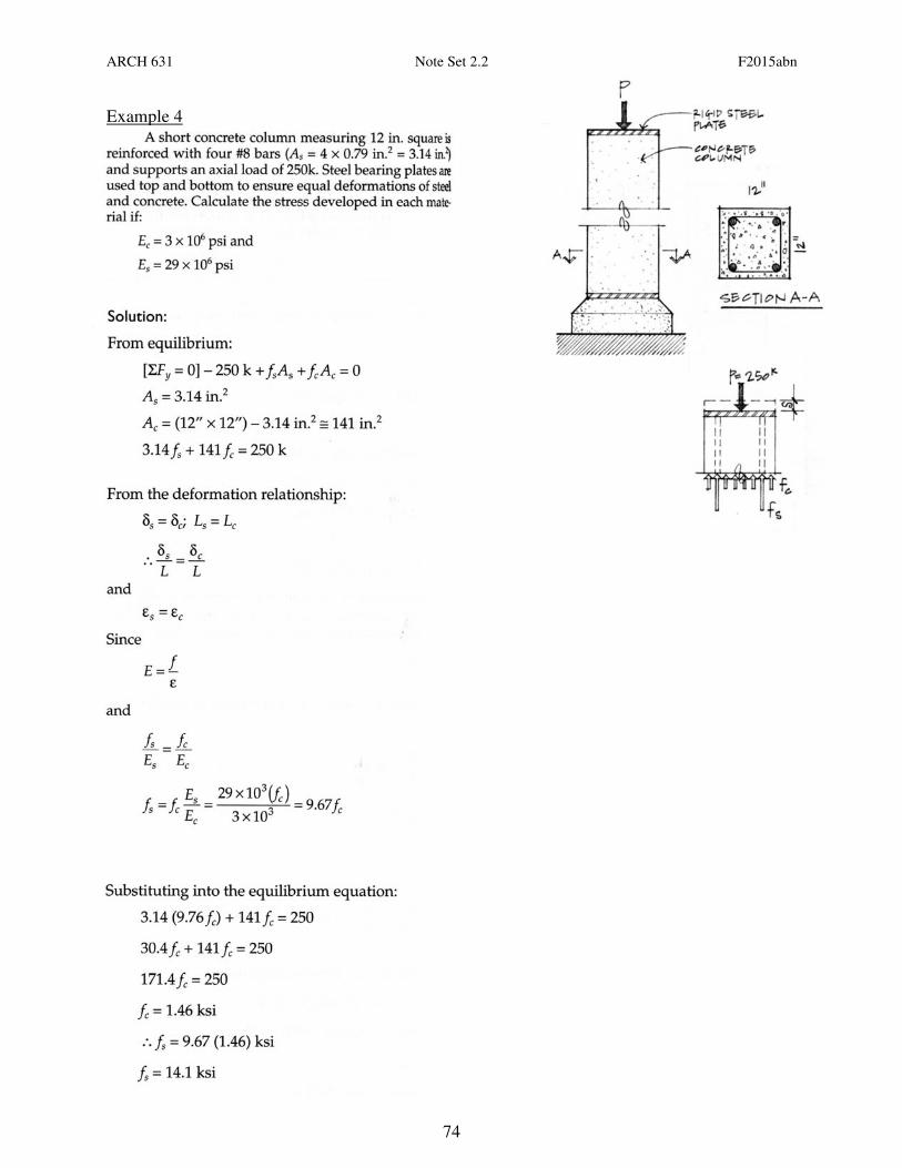
Example 4
ARCH 631 Note Set 2.2 F2015abn
75
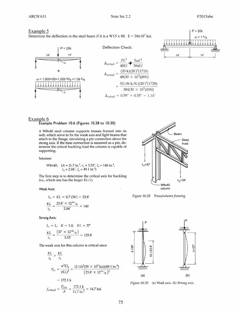
Example 5 Determine the deflection in the steel beam if it is a W15 x 88. E = 30x10
3 ksi.
Example 6


