
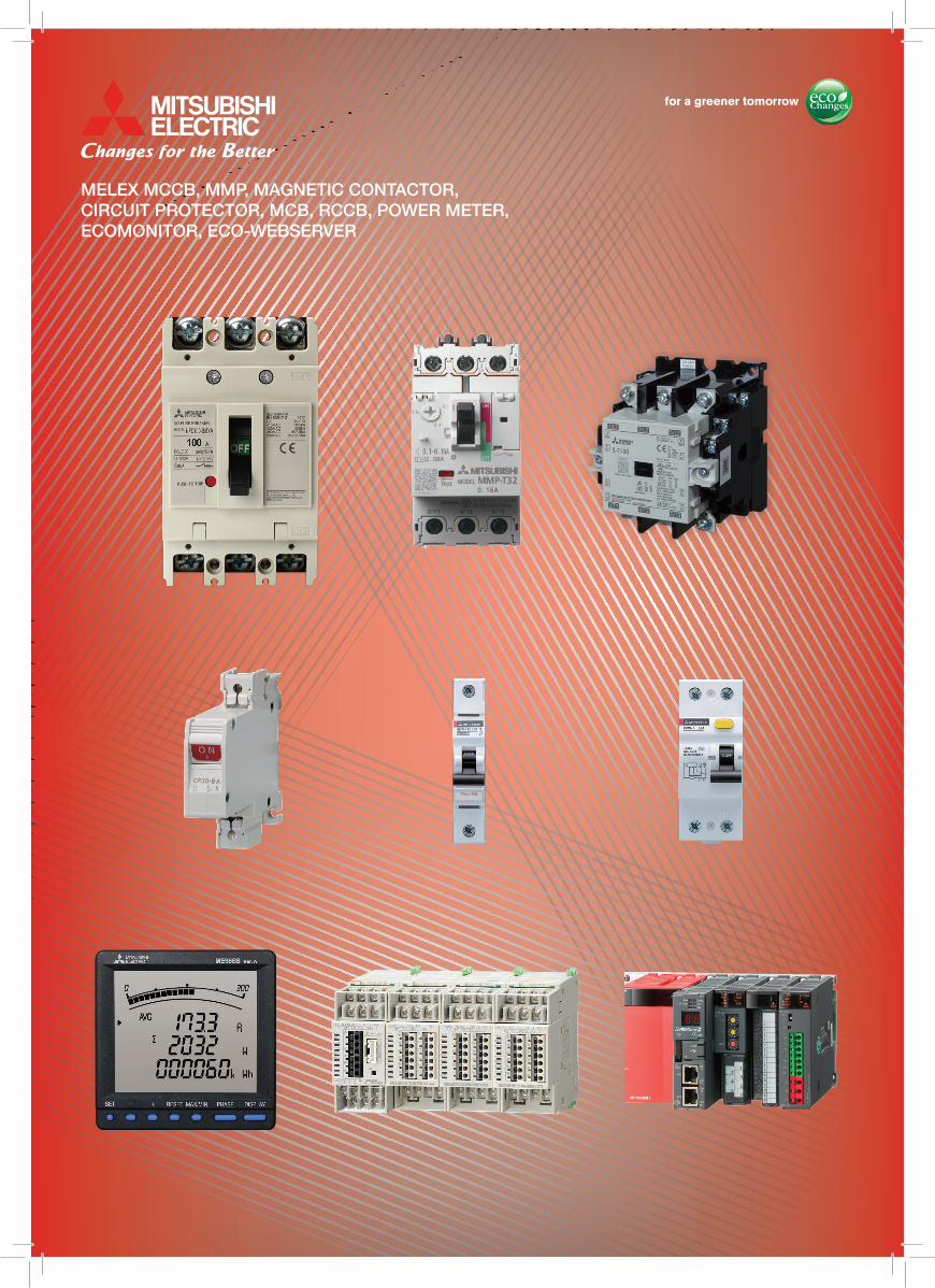
MELEX MCCB, MMP, MAGNETIC CONTACTOR,CIRCUIT PROTECTOR, MCB, RCCB, POWER METER,ECOMONITOR, ECO-WEBSERVER


Contents
INDEX
1 MOLDED CASE CIRCUIT BREAKERS
1) Melex 1
2) WS-V 2 – 6
3) Earth Leakage Circuit Breaker 7 – 10
4) Japan Series 8 – 20
2 MOTOR CIRCUIT BREAKERS 21
3 MAGNETIC CONTACTOR 22 – 23
4 CIRCUIT PROTECTORS 24 – 27
5 MCB / RCCB / ISOLATOR 28
6 POWER METER 29
7 ECO MONITOR PLUS 30
8 ECO WEBSERVER 31

1
1-1 Molded Case Circuit Breakers — Melex
Specifications

2
1-2 Molded Case Circuit Breakers — WS-V
14
2
NF-C (Economy class)
Frame (A) 30 50 60 63 100 125Model NF30-CS NF63-CV NF125-CV
Image
Rated current In (A)Rated ambient temperture 40°C (45°C for marine use) 3 5 10 15 20 30 3 4 (5) 6 10 (15) 16
20 25 (30) 32 40 50 (60) 63 50 (60) 63(75) 80 100 125
Number of poles 2 3 2 3 2 3 2 3 2 3 2 3Rated insulation voltage Ui (V) 500 600 600 600 600 600
Rated
short
-circu
it brea
king c
apac
ities (
kA)
IEC 60947-2EN 60947-2(Icu/Ics)
AC
690V − − − − − −500V − 2.5/2.5 2.5/2.5 2.5/2.5 7.5/4 7.5/4440V − 2.5/2.5 2.5/2.5 2.5/2.5 10/5 10/5415V 1.5/1.5 2.5/2.5 2.5/2.5 2.5/2.5 10/5 10/5400V 1.5/1.5 5/5 5/5 5/5 10/5 10/5380V 1.5/1.5 5/5 5/5 5/5 10/5 10/5230V 2.5/2 (240V) 7.5/7.5 7.5/7.5 7.5/7.5 30/15 30/15200V 2.5/2 (240V) 7.5/7.5 7.5/7.5 7.5/7.5 30/15 30/15
DC 250V − 2.5/2.5 (*7) 2.5/2.5 (*7) 2.5/2.5 (*7) 7.5/4 (*4) 7.5/4 (*4)Rated impulse withstand voltage Uimp (kV) 4 8 8 8 8 8
Current (*1) AC AC/DC compatible AC/DC compatible AC/DC compatible AC/DC compatible AC/DC compatibleSuitability for isolation − Compatible Compatible Compatible Compatible CompatibleReverse connection − Possible Possible Possible Possible Possible
Number ofoperating cycles
Without current 10,000 10,000 10,000 10,000 10,000 10,000With current (440VAC) 6,000 (AC415V) 6,000 6,000 6,000 6,000 6,000
Utilization category A A A A A APollution degree 2 3 3 3 3 3
EMC environment condition (environment A or B) N/A N/A N/A N/A N/A N/A
Overa
lldim
ensio
ns (m
m) a
b
cac a 45 67.5 50 75 50 75 50 75 60 90 60 90
b 96 130 130 130 130 130c 52 68 68 68 68 68
ca 67 90 90 90 90 90Mass of front-face type (kg) 0.25 0.35 0.45 0.65 0.5 0.7 0.5 0.7 0.6 0.9 0.6 0.9
Instal
lation
and
conn
ectio
ns Front connection (F) Page �Screw terminal �Screw terminal �Screw terminal �Screw terminal �Screw terminal �Screw terminalSolderless (BOX) terminal (SL)
94− − − − � �
Rear (B) �Round stud (assembled in) �Round stud �Round stud �Round stud �Bar stud �Bar stud Plug-in (PM) − � � � � �
Cas
sette
-typ
e ac
cess
orie
s
Alarm switch (AL)
104
� (*5) � (*6) � (*6) � (*6) � (*6) �(*6)Auxiliary switch (AX) �(*5) � (*6) � (*6) � (*6) � (*6) �(*6)Shunt trip (SHT) − � (*6) � (*6) � (*6) � (*6) �(*6)Undervoltage trip (UVT) − � (*6) � (*6) � (*6) � (*6) �(*6)With lead-wire terminal block (SLT) 116 � � � � � �
Pre-alarm (PAL) 118 − − − − − −
Ext
erna
l acc
esso
ries
EnclosureClosed (S)
132� � � � � �
Dustproof (I) − � � � � �
Waterproof (W) − − � − � − � − � − �
Electrical operation device (NFM) 135 − − − − − � − �
Mechanicalinterlock (MI) (*10)
Panel mounting131
− � � � � �
Breaker mounting − � � � � �
Handle lockdevice
LC129
� � � � � �
HL � � � � � �
HL-S − � � � � �
Externaloperating handle
(F)119
− � � � � �
(V) − � � � � �
Terminal cover (TC-L, TC-S, TTC, BTC, PTC) 123 � � � � � �
Rear stud (B-ST)96
− � � � � �
Plug-in (PM) − � � � � �
IEC 35mm rail mounting adapters 139 � � � � − −CE marking TÜV approval Self-declaration Self-declaration Self-declaration Self-declaration Self-declaration
CCC recognition Recognition in process Recognition in process Recognition in process Recognition in process Recognition in process Recognition in processMarine use approval (NK, LR, ABS, GL) � (NK, LR, ABS) � � � � �
Automatic tripping device Hydraulic magnetic Thermal-magnetic Thermal-magnetic Thermal-magnetic Thermal-magnetic Thermal-magneticTrip button − (*2) Equipped Equipped Equipped Equipped Equipped
Page of Characteristics and dimensions 142 144 146
1D
etai
led
Spe
cific
atio
ns
2 Molded Case Circuit BreakersDetailedSpecifications 1
Notes: *1 The trip action characteristics differ between AC and DC for products that are compatible with both AC and DC. *2 It is attached with the alarm switch. *3 In case of a current rating of 100A, it does not specify NK rating. *4 Use two poles for three- and four-pole products. In this case, do not use the neutral pole of the four-pole products.
If wired as shown on the right, three and four poles can be used for up to 400 and 500VDC, respectively. *5 The standard lead drawing is performd laterally. Load drawing is also available. *6 The cassette type design makes it easy for customer to install. Available for installation on side below 250A frame
(excluding UVT). *7 Use two poles for three- and four-pole products. In this case, do not use the neutral pole of the four-pole products. Not available for use with connection as shown on the right. *8 Place an order of other models in conjunction with the circuit breaker. *9 Solid state relay output is option. Please specify if other output is necessary.
(Standard type is thus SLT equipped). *10 Not isolation compatible, excluding 400 to 800A frame.
Line
3-poleLoad
Line
4-poleLoad

3
1-2 Molded Case Circuit Breakers — WS-V
16
2
1D
etai
led
Spe
cific
atio
ns
NF-S (Standard class)
Frame (A) 30 32 50 60 63Model NF32-SV NF63-SV
Image
Rated current In (A)Rated ambient temperture 40°C (45°C for marine use)
3 4 (5) 6 1015 16 20 25 (30) 32 3 4 (5) 6 10 (15) 16
20 25 (30) 32 40 50 (60) 63
Number of poles 2 3 2 3 2 3 4 2 3 4 2 3 4Rated insulation voltage Ui (V) 600 600 600 600 600
Rated
short
-circu
it brea
king c
apac
ities (
kA)
IEC 60947-2EN 60947-2(Icu/Ics)
AC
690V − − − − −500V 2.5/2.5 2.5/2.5 7.5/7.5 7.5/7.5 7.5/7.5440V 2.5/2.5 2.5/2.5 7.5/7.5 7.5/7.5 7.5/7.5415V 2.5/2.5 2.5/2.5 7.5/7.5 7.5/7.5 7.5/7.5400V 5/5 5/5 7.5/7.5 7.5/7.5 7.5/7.5380V 5/5 5/5 7.5/7.5 7.5/7.5 7.5/7.5230V 7.5/7.5 7.5/7.5 15/15 15/15 15/15200V 7.5/7.5 7.5/7.5 15/15 15/15 15/15
DC 250V 2.5/2.5 (*5) 2.5/2.5 (*5) 7.5/7.5 (*5) 7.5/7.5 (*5) 7.5/7.5 (*5)Rated impulse withstand voltage Uimp (kV) 8 8 8 8 8
Current (*1) AC/DC compatible AC/DC compatible AC/DC compatible AC/DC compatible AC/DC compatibleSuitability for isolation Compatible Compatible Compatible Compatible CompatibleReverse connection Possible Possible Possible Possible Possible
Number ofoperating cycles
Without current 10,000 10,000 10,000 15,000 15,000With current (440VAC) 6,000 6,000 6,000 8,000 8,000
Utilization category A A A A APollution degree 3 3 3 3 3
EMC environment condition (environment A or B) N/A N/A N/A N/A N/A
Overa
lldim
ensio
ns (m
m) a
b
cac a 50 75 50 75 50 75 100 50 75 100 50 75 100
b 130 130 130 130 130c 68 68 68 68 68
ca 90 90 90 90 90Mass of front-face type (kg) 0.45 0.65 0.45 0.65 0.5 0.7 0.9 0.55 0.75 1.0 0.55 0.75 1.0
Instal
lation
and
conn
ectio
ns Front connection (F) Page �Screw terminal �Screw terminal �Screw terminal �Screw terminal �Screw terminalSolderless (BOX) terminal (SL)
94− − − − −
Rear (B) �Bar stud �Round stud �Round stud �Round stud �Round stud Plug-in (PM) � � � � �
Cas
sette
-typ
e ac
cess
orie
s
Alarm switch (AL)
104
� (*4) � (*4) � (*4) � � (*4) � � (*4) �
Auxiliary switch (AX) � (*4) � (*4) � (*4) � � (*4) � � (*4) �
Shunt trip (SHT) � (*4) � (*4) � (*4) � � (*4) � � (*4) �
Undervoltage trip (UVT) � (*4) � (*4) � (*4) � � (*4) � � (*4) �
With lead-wire terminal block (SLT) 116 � � � � � � � �
Pre-alarm (PAL) 118 − − − − −
Ext
erna
l acc
esso
ries
EnclosureClosed (S)
132� � � − � − � −
Dustproof (I) � � � − � − � −Waterproof (W) − � − � − � − − � − − � −
Electrical operation device (NFM) 135 − − − − −Mechanical
interlock (MI) (*7)Panel mounting
131� � � � � � � �
Breaker mounting � � � − � − � −
Handle lockdevice
LC129
� � � � �
HL � � � � �
HL-S � � � � �
Externaloperating handle
(F)119
� � � � �
(V) � � � � �
Terminal cover (TC-L, TC-S, TTC, BTC, PTC) 123 � � � � � � � �
Rear stud (B-ST)96
� � � � �
Plug-in (PM) � � � � � � � �
IEC 35mm rail mounting adapters 139 � � � − � − � −CE marking Self-declaration Self-declaration Self-declaration Self-declaration Self-declaration
CCC recognition Recognition in process Recognition in process Recognition in process Recognition in process Recognition in processMarine use approval (NK, LR, ABS, GL) � � � − � − � −
Automatic tripping device Thermal-magnetic Thermal-magnetic Thermal-magnetic Thermal-magnetic Thermal-magneticTrip button Equipped Equipped Equipped Equipped Equipped
Page of Characteristics and dimensions 144 144
Notes: *1 The trip action characteristics differ between AC and DC for products that are compatible with both AC and DC. *2 In case of a current rating of 100A, it does not specify NK rating. *3 Use two poles for three- and four-pole products. In this case, do not use the neutral pole of the four-pole products.
If wired as shown on the right, three and four poles can be used for up to 400 and 500VDC, respectively.(In case of NF250-SV, three and four poles can be used for up to 500 and 600VDC)
*4 The cassette type design makes it easy for customer to install. Available for installation on side below 250A frame (excluding UVT).
*5 Use two poles for three- and four-pole products. In this case, do not use the neutral pole of the four-pole products. Not available for use with connection as shown on the right. *6 Place an order of other models in conjunction with the circuit breaker. *7 Not isolation compatible. excluding 400 to 800A frame.
Line
3-poleLoad
Line
4-poleLoad
2 Molded Case Circuit BreakersDetailedSpecifications 1

4
17
2
1D
etai
led
Spe
cific
atio
ns
NF-S (Standard class)
100 125 125 125 160 225 250NF125-SV NF125-SGV NF125-SEV NF160-SGV NF250-SV
(15) 16 20 (30) 32 4050 (60) 63 (75) 80 100 125 16-20 20-25 25-32 32-40 35-50
45-63 56-80 70-100 90-125 16-32 32-63 63-125 125-160 (100) 125 150 160175 200 225 (*2) 250
2 3 4 2 3 4 2 3 4 3 4 2 3 4 2 3 4 2 3 4690 690 690 690 690 690 6908/8 8/8 8/8 8/8 8/8 8/8 8/8
18/18 18/18 30/30 30/30 30/30 30/30 30/3025/25 25/25 36/36 36/36 36/36 36/36 36/3630/30 30/30 36/36 36/36 36/36 36/36 36/3630/30 30/30 36/36 36/36 36/36 36/36 36/3630/30 30/30 36/36 36/36 36/36 36/36 36/3650/50 50/50 85/85 85/85 85/85 85/85 85/8550/50 50/50 85/85 85/85 85/85 85/85 85/85
40/40 (*3) 40/40 (*3) 20/20 (300V) (*3) − 20/20 (300V) (*3) 20/20 (300V) (*3) 20/20 (300V) (*3)8 8 8 8 8 8 8
AC/DC compatible AC/DC compatible AC/DC compatible AC AC/DC compatible AC/DC compatible (*1) AC/DC compatible (*1)Compatible Compatible Compatible Compatible Compatible Compatible Compatible
Possible Possible Possible Possible Possible Possible Possible25,000 25,000 50,000 25,000 40,000 25,000 25,00010,000 10,000 30,000 10,000 15,000 10,000 10,000
A A A A A A A3 3 3 3 3 3 3
N/A N/A N/A A N/A N/A N/A60 90 120 60 90 120 105 140 105 140 105 140 105 140 105 140
130 130 165 165 165 165 16568 68 68 68 68 68 6890 90 92 92 92 92 92
0.7 1.0 1.3 0.7 1.0 1.3 1.4 1.6 2.0 1.7 2.2 1.4 1.6 2.0 1.4 1.6 2.0 1.4 1.6 2.0�Screw terminal �Screw terminal �Screw terminal �Screw terminal �Screw terminal �Screw terminal �Screw terminal
� � � � � � � � � � �Bar stud �Bar stud �Bar stud �Bar stud �Bar stud �Bar stud �Bar stud �Bar stud � � � � � � � � � � � �
� (*4) � � (*4) � � (*4) � � (*4) � � (*4) � � (*4) � � (*4) �
� (*4) � � (*4) � � (*4) � � (*4) � � (*4) � � (*4) � � (*4) �
� (*4) � � (*4) � � (*4) � � (*4) � � (*4) � � (*4) � � (*4) �
� (*4) � � (*4) � � (*4) � � (*4) � � (*4) � � (*4) � � (*4) �
� � � � � � � � � � � �
− − − � − − −� − � − � − � − � − � − � −� − � − � − � − � − � − � −
− � − − � − � − � − � − � − � −− � − � � � � � �
� � � � � � � � � � � �
� − � − � � − � � − � −� � � � � � �
� � � � � � �
� � � � � � �
� � � � � � �
− � � − � � � � � �
� � � � � � � � � � � �
� � � � � � � � � � � �
� � � � � � � � � � � �
− − − − − − −Self-declaration Self-declaration Self-declaration Self-declaration Self-declaration TÜV approval Self-declaration TÜV approval Self-declaration
Recognition in process Recognition in process Recognition in process Recognition in process Recognition in process Recognition in process Recognition in process� − � − � (LR, ABS, GL) − � (LR, ABS, GL) − � (LR, ABS, GL) − � − � −
Thermal-magnetic Thermal-magnetic Thermal-magnetic Electronic (effective value detection) Thermal-magnetic Thermal-magnetic Thermal-magneticEquipped Equipped Equipped Equipped Equipped Equipped Equipped
146 154 156 154 150
Remarks: 1. Products with rated current parenthesized are produced when an order is placed. 2. Specify “P-LT” when using a plug-in product with a lead-wire terminal block. 3. The circuit breaker has the rated short-circuit breaking capacity specifi ed in the shaded cells.
2 Detailed Specifications 1Molded Case Circuit Breakers

5
1-2 Molded Case Circuit Breakers — WS-V
20
2
1D
etai
led
Spe
cific
atio
ns
NF-L / NF-H / NF-R (High-performance class)
Frame (A) 50 60 63 100 125 125 125 125Model NF63-HV NF125-HV NF125-LGV NF125-HGV NF125-RGV
Image
Rated current In (A)Rated ambient temperture 40°C (45°C for marine use)
10 15 16 20 25 30 32 40 50 60 (63) 15 16 20 30 32 40
50 60 63 75 80 100 125 16-20 20-25 25-32 32-40 35-5045-63 56-80 70-100 90-125
16-20 20-25 25-32 32-40 35-5045-63 56-80 70-100 90-125
16-20 20-25 25-32 32-40 40-5050-63 63-80 80-100 100-125
Number of poles 2 3 4 2 3 4 2 3 4 2 3 4 2 3 4 2 3 4 2 3 4 2 3Rated insulation voltage Ui (V) 690 690 690 690 690 690 690 690
Rated
short
-circu
it brea
king c
apac
ities (
kA)
IEC 60947-2EN 60947-2(Icu/Ics)
AC
690V 2.5/2.5 2.5/2.5 2.5/2.5 10/8 10/8 8/8 10/8 –500V 7.5/7.5 7.5/7.5 7.5/7.5 30/23 30/23 36/36 50/38 –440V 10/8 10/8 10/8 50/38 50/38 50/50 65/65 125/125415V 10/8 10/8 10/8 50/38 50/38 50/50 70/70 150/150400V 10/8 10/8 10/8 50/38 50/38 50/50 75/75 150/150380V 10/8 10/8 10/8 50/38 50/38 50/50 75/75 150/150230V 25/19 25/19 25/19 100/75 100/75 90/90 100/100 150/150200V 25/19 25/19 25/19 100/75 100/75 90/90 100/100 150/150
DC 250V 7.5/7.5 (*5) 7.5/7.5 (*5) 7.5/7.5 (*5) − − 20/20 (300V) (*2) 40/40 (300V) (*2) −Rated impulse withstand voltage Uimp (kV) 8 8 8 8 8 8 8 8
Current AC/DC compatible (*1) AC/DC compatible (*1) AC/DC compatible (*1) AC AC AC/DC compatible AC/DC compatible ACSuitability for isolation Compatible Compatible Compatible Compatible Compatible Compatible Compatible CompatibleReverse connection Possible Possible Possible Possible Possible Possible Possible Possible
Number ofoperating cycles
Without current 15,000 15,000 15,000 25,000 25,000 50,000 50,000 50,000With current (440VAC) 8,000 8,000 8,000 10,000 10,000 30,000 30,000 30,000
Utilization category A A A A A A A APollution degree 3 3 3 3 3 3 3 3
EMC environment condition (environment A or B) N/A N/A N/A N/A N/A N/A N/A N/A
Overa
lldim
ensio
ns (m
m) a
b
cac a 50 75 100 50 75 100 50 75 100 90 120 90 120 105 140 105 140 105
b 130 130 130 130 130 165 165 165c 68 68 68 68 68 68 68 68ca 90 90 90 90 90 92 92 92
Mass of front-face type (kg) 0.5 0.7 0.9 0.55 0.75 1.0 0.55 0.75 1.0 0.8 1.0 1.3 0.8 1.0 1.3 1.4 1.6 2.0 1.4 1.6 2.0 1.5 1.8
Instal
lation
and
conn
ectio
ns Front connection (F) Page �Screw terminal �Screw terminal �Screw terminal �Screw terminal �Screw terminal � � �Screw terminalSolderless (BOX) terminal (SL)
94� � � � � � � �
Rear (B) �Round stud �Round stud �Round stud �Bar stud �Bar stud �Bar stud �Bar stud �Bar stud Plug-in (PM) � � � � � � � � � �
Cas
sette
-typ
e ac
cess
orie
s
Alarm switch (AL)
104
� (*3) � � (*3) � � (*3) � � (*3) � � (*3) � � (*3) � � (*3) � � (*3)Auxiliary switch (AX) � (*3) � � (*3) � � (*3) � � (*3) � � (*3) � � (*3) � � (*3) � � (*3)Shunt trip (SHT) � (*3) � � (*3) � � (*3) � � (*3) � � (*3) � � (*3) � � (*3) � � (*3)Undervoltage trip (UVT) � (*3) � � (*3) � � (*3) � � (*3) � � (*3) � � (*3) � � (*3) � � (*3)With lead-wire terminal block (SLT) 116 � � � � � � � � � � � � �
Pre-alarm (PAL) 118 − − − − − − − −
Ext
erna
l acc
esso
ries
EnclosureClosed (S)
132� − � − � − � − � − � − − −
Dustproof (I) � − � − � − � − � − � − � − −Waterproof (W) − � − − � − − � − � − � − � − � − −
Electrical operation device (NFM) 135 − − − � � � � �
Mechanicalinterlock (MI) (*4)
Panel mounting131
� � � � � � � � � � � � �
Breaker mounting � − � − � − � − � − � � �
Handle lockdevice
LC129
� � � � � � � �
HL � � � � � � � �
HL-S � � � � � � � �
Externaloperating handle
(F)119
� � � � � � � �
(V) � � � � � � � �
Terminal cover (TC-L, TC-S, TTC, BTC, PTC) 123 � � � � � � � � � � � � �
Rear stud (B-ST)96
� � � � � � � � � � � −Plug-in (PM) � � � � � � � � � � � � � � �
IEC 35mm rail mounting adapters 139 � − � − � − − − − − −CE marking Self-declaration Self-declaration Self-declaration Self-declaration Self-declaration Self-declaration Self-declaration Self-declaration
CCC recognition Recognition in process Recognition in process Recognition in process Recognition in process Recognition in process Recognition in process Recognition in process Recognition in processMarine use approval (NK, LR, ABS, GL) � − � − � − � − � − � (LR, ABS, GL) − � (LR, ABS, GL) − � (LR, ABS, GL)
Automatic tripping device Thermal-magnetic Thermal-magnetic Thermal-magnetic Thermal-magnetic Thermal-magnetic Thermal-magnetic Thermal-magnetic Thermal-magneticTrip button Equipped Equipped Equipped Equipped Equipped Equipped Equipped Equipped
Page of Characteristics and dimensions 144 146 154 154 154
Notes: *1 The trip action characteristics differ between AC and DC for products that are compatible with both AC and DC. *2 Use two poles for three- and four-pole products. In this case, do not use the neutral pole of the four-pole products.
If wired as shown on the right, three and four poles can be used for up to 500 and 600VDC, respectively. *3 The cassette type design makes it easy for customer to install. Available for installation on side below 250A frame
(excluding UVT). *4 Not isolation compatible, excluding 400 to 800A frame. *5 Use two poles for three- and four-pole products. In this case, do not use the neutral pole of the four-pole products.
Not available for use with connection as shown on the right.
Line
3-poleLoad
Line
4-poleLoad
Available soon
2 Molded Case Circuit BreakersDetailedSpecifications 1

6
22
2
1D
etai
led
Spe
cific
atio
ns
Frame (A) 250 400 630 800Model NF250-HEV NF400-HEW NF400-REW NF630-HEW NF630-REW NF800-HEW NF800-REW
Image
Rated current In (A)Rated ambient temperture 40°C (45°C for marine use) 80-160 125-250 Adjustable 200 225
250 300 350 400Adjustable 200 225 250 300 350 400
Adjustable 300 350400 500 600 630
Adjustable 300 350400 500 600 630
Adjustable 400 450500 600 700 800
Adjustable 400 450500 600 700 800
Number of poles 3 4 3 4 3 3 4 3 3 4 3Rated insulation voltage Ui (V) 690 690 690 690 690 690 690
Rated
short
-circu
it brea
king c
apac
ities (
kA)
IEC 60947-2EN 60947-2(Icu/Ics)
AC
690V 10/8 35/18 − 35/18 − 15/15 −500V 50/38 50/50 70/35 50/50 70/35 50/50 70/35440V 65/65 65/65 125/63 65/65 125/63 65/65 125/63415V 70/70 70/70 125/63 70/70 125/63 70/70 125/63400V 75/75 70/70 125/63 70/70 125/63 70/70 125/63380V 75/75 70/70 125/63 70/70 125/63 70/70 125/63230V 100/100 100/100 150/75 100/100 150/75 100/100 150/75200V 100/100 100/100 150/75 100/100 150/75 100/100 150/75
DC 250V − − − − − − −Rated impulse withstand voltage Uimp (kV) 8 8 8 8 8 8 8
Current AC AC AC AC AC AC ACSuitability for isolation Compatible Compatible Compatible Compatible Compatible Compatible CompatibleReverse connection Possible Possible Possible Possible Possible Possible Possible
Number ofoperating cycles
Without current 25,000 6,000 6,000 6,000 6,000 4,000 4,000With current (440VAC) 10,000 1,000 1,000 1,000 1,000 500 500
Utilization category A B B B B B BRated short time with stand current Icu (kA) at 0.25s − 5 5 7.6 7.6 9.6 9.6
Pollution degree 3 3 3 3 3 3 3EMC environment condition (environment A or B) A A A A A A A
Overa
lldim
ensio
ns (m
m) a
b
cac a 105 140 140 185 140 140 185 140 210 280 210
b 165 257 257 257 257 275 275c 68 103 103 103 103 103 103ca 92 155 155 155 155 155 155
Mass of front-face type (kg) 1.7 2.2 6.0 7.6 6.0 6.5 8.3 6.0 10.9 14.2 10.9
Instal
lation
and
conn
ectio
ns Front connection (F) Page �Screw terminal �Busbar terminal �Busbar terminal �Busbar terminal �Busbar terminal �Busbar terminal �Busbar terminal �Busbar terminal �Busbar terminalSolderless (BOX) terminal (SL)
94� � � � � � � � � � �
Rear (B) �Bar stud �Bar stud �Bar stud �Bar stud �Bar stud �Bar stud �Bar stud �Bar stud �Bar stud �Bar stud Plug-in (PM) � � � � � � � � � � �
Cas
sette
-typ
e ac
cess
orie
s
Alarm switch (AL)
104
� (*1) � � (*1) � � (*1) � (*1) � � (*1) � (*1) � � (*1)Auxiliary switch (AX) � (*1) � � (*1) � � (*1) � (*1) � � (*1) � (*1) � � (*1)Shunt trip (SHT) � (*1) � � (*1) � � (*1) � (*1) � � (*1) � (*1) � � (*1)Undervoltage trip (UVT) � (*1) � � � � � � � � � �
With lead-wire terminal block (SLT) 116 � � � � � � � � � � �
Pre-alarm (PAL) 118 � � (*2) � (*2) � (*2) � (*2) � (*2) � (*2)
Ext
erna
l acc
esso
ries
EnclosureClosed (S)
132− − − − − − −
Dustproof (I) � − − − − − − −Waterproof (W) � − − − − − − −
Electrical operation device (NFM) 135 � � (*3) � (*3) � (*3) � (*3) � (*3) � (*3)Mechanical
interlock (MI) (*4)Panel mounting
131� � � � � � � � � � �
Breaker mounting � − � − � � − � � − �
Handle lockdevice
LC129
� − − − − − −HL � � � � � � �
HL-S � � � � � � �
Externaloperating handle
(F)119
� � � � � � �
(V) � � � � � � �
Terminal cover (TC-L, TC-S, TTC, BTC, PTC) 123 � � � � � � � � � �
Rear stud (B-ST)96
� � � � � � � � � �
Plug-in (PM) � � � � � � � � �
IEC 35mm rail mounting adapters 139 − − − − − − −CE marking Self-declaration Self-declaration Self-declaration Self-declaration Self-declaration Self-declaration Self-declaration
CCC recognition Recognition in process Recognition in process Recognition in process Recognition in process Recognition in process Recognition in process Recognition in processMarine use approval (NK, LR, ABS, GL) � (LR, ABS, GL) − � − � � − � � − �
Automatic tripping device Electronic (effective value detection) Electronic (effective value detection) Electronic (effective value detection) Electronic (effective value detection) Electronic (effective value detection) Electronic (effective value detection) Electronic (effective value detection)Trip button Equipped Equipped Equipped Equipped Equipped Equipped Equipped
Page of Characteristics and dimensions 156 160 160 166 166 168 168
NF-H / NF-R (High-performance class)
Notes: *1 The cassette type design makes it easy for customer to install. Available for installation on side below 250A frame (excluding UVT).
*2 Solid state relay output is option. Please specify if other output is necessary. (Standard type is thus SLT equipped).
*3 Place an order of other models in conjunction with the circuit breaker. *4 Not isolation compatible, excluding 400 to 800A frame.
Line
3-poleLoad
Line
4-poleLoad
2 Molded Case Circuit BreakersDetailedSpecifications 1

7
1-3 Earth Leakage Circuit Breakers
26
2
2D
etai
led
Spe
cific
atio
ns
NV-S (Standard class) Harmonic Surge Ready Frame (A) 30 32 50 60 63 100 125 125
Model NV32-SV NV63-SV NV125-SV NV125-SEV
Image
Rated current In (A)Rated ambient temperture 40°C
(5) 6 10 (15) 16 20 25 (30) (32) (5) (10) (15) 16 20
25 (30) 32 40 50 (60) 63 (15) 16 20 (30) 32 40 50 (60) 63 (75) 80 100 (*3) 125 63-125
Number of poles 3 3 3 3 3 3 4 3 4 3 4
Phase line (*1) 3f3W, 1f3W,1f2W
3f3W, 1f3W,1f2W
3f3W, 1f3W,1f2W
3f3W, 1f3W,1f2W
3f3W, 1f3W,1f2W
3f3W,1f3W,1f2W
3f4W3f3W,1f3W,1f2W
3f4W 3f3W, 1f2W 3f4W
Rated operational voltage Ue (V) (*2) AC 100-440 100-440 100-440 100-440 100-440 100-440 200-440 100-440 200-440 100-440
Hig
h-sp
eed
type
Rated current sensitivity (mA) 30,100/200/500selectable
30,100/200/500selectable
30,100/200/500selectable
30,100/200/500selectable
30,100/200/500selectable
30,100/200/500selectable
30,100/200/500selectable
(30),100/200/500selectable
Max. operating time (s)at IΔn 0.1 0.1 0.1 0.1 0.1 0.1 0.1 0.1at 5IΔn 0.04 0.04 0.04 0.04 0.04 0.04 0.04 0.04
Tim
e-de
lay
type
Rated current sensitivity (mA) − − − − − (100/200/500selectable) (100/200/500selectable) (100/200/500selectable)Max. operating time (s) (*4) − − − − − (0.45/1.0/2.0selectable) (0.45/1.0/2.0selectable) (0.45/1.0/2.0selectable)Internal non-operating (s) (or more) − − − − − (0.1/0.5/1.0) (0.1/0.5/1.0) (0.1/0.5/1.0)
Earth leakage indication system Mechanical type (button) Mechanical type (button) Mechanical type (button) Mechanical type (button) Mechanical type (button) Mechanical type (button) Mechanical type (button) Mechanical type (button)
Rated
short
-circu
itbre
aking
capa
cities
(kA)
IEC 60947-2EN 60947-2(Icu/Ics)
AC
440V 5/5 5/5 7.5/7.5 7.5/7.5 7.5/7.5 25/25 25/25 36/36415V 5/5 5/5 7.5/7.5 7.5/7.5 7.5/7.5 30/30 30/30 36/36400V 5/5 5/5 7.5/7.5 7.5/7.5 7.5/7.5 30/30 30/30 36/36230V 10/10 10/10 15/15 15/15 15/15 50/50 50/50 85/85200V 10/10 10/10 15/15 15/15 15/15 50/50 50/50 85/85100V 10/10 10/10 15/15 15/15 15/15 50/50 − 50/50 − 85/85
Rated impulse withstand voltage Uimp (kV) 6 6 6 6 6 6 6 6Current AC AC AC AC AC AC AC AC
Suitability for isolation Compatible Compatible Compatible Compatible Compatible Compatible Compatible CompatibleReverse connection (below 230VAC) Possible Possible Possible Possible Possible Possible Possible Possible
Number ofoperating cycles
Without current 10,000 10,000 15,000 15,000 15,000 25,000 25,000 25,000With current 6,000 6,000 8,000 8,000 8,000 10,000 10,000 10,000
Utilization category A A A A A A A ARated short time withstand current Icu (kA) at 0.25s − − − − − − − −
Pollution degree 2 2 2 2 2 2 2 2EMC environment condition (environment A or B) A A A A A A A A
Overa
lldim
ensio
ns (m
m) a
b
cac a 75 75 75 75 75 90 120 90 120 105 140
b 130 130 130 130 130 130 130 165c 68 68 68 68 68 68 68 68ca 90 90 90 90 90 90 90 92
Mass of front-face type (kg) 0.75 0.75 0.75 0.8 0.8 1.1 1.4 1.1 1.4 1.9 2.5
Instal
lation
and
conn
ectio
ns Front connection (F) Page �Screw terminal �Screw terminal �Screw terminal �Screw terminal �Screw terminal �Screw terminal �Screw terminal �
Solderless (BOX) terminal (SL)94
− − − − − − − −Rear (B) �Round stud �Round stud �Round stud �Round stud �Round stud �Bar stud �Bar stud �Bar stud Plug-in (PM) − − − − − − − −
Cas
sette
-typ
e ac
cess
orie
s
Alarm switch (AL)
104
� (*5) � (*5) � (*5) � (*5) � (*5) � (*5) � � (*5) � � (*5) �
Auxiliary switch (AX) � (*5) � (*5) � (*5) � (*5) � (*5) � (*5) � � (*5) � � (*5) �
Shunt trip (SHT) � (*5) � (*5) � (*5) � (*5) � (*5) � (*5) � � (*5) � � (*5) �
Undervoltage trip (UVT) � (*5) � (*5) � (*5) � (*5) � (*5) � (*5) � � (*5) � � (*5) �
Earth leakage alarm switch (EAL) − − − − − − − −With lead-wire terminal block (SLT) 116 � � � � � � � � � �
Test button module (TBM) 117 � (*6) � (*6) � (*6) � (*6) � (*6) � (*6) � (*6) � (*6)
Ext
erna
l acc
esso
ries
EnclosureClosed (S)
132− − − − − − − � −
Dustproof (I) − − − − − − − � −Waterproof (W) − − − − − − − � −
Electrical operation device (NFM) 135 − − − − − � � �
Mechanicalinterlock (MI) (*8)
Panel mounting131
� � � � � � � � � �
Breaker mounting � � � � � � − � − � −
Handle lockdevice
LC129
� � � � � � � �
HL � � � � � � � �
HL-S � � � � � � � �
Externaloperating handle
(F)119
� � � � � � � �
(V) � � � � � � � �
Terminal cover (TC-L, TC-S, TTC, BTC, PTC) 123 � � � � � � � �
Rear stud (B-ST)96
� � � � � � � �
Plug-in (PM) − − − − − − − −IEC 35mm rail mounting adapters 139 � � � � � − − −
CE marking Self-declaration Self-declaration Self-declaration Self-declaration Self-declaration Self-declaration Self-declaration Self-declarationCCC recognition Recognition in process Recognition in process Recognition in process Recognition in process Recognition in process Recognition in process Recognition in process Recognized
Marine use approval (NK, LR, ABS, GL) − − − − − − − −Automatic tripping device Thermal-magnetic Thermal-magnetic Thermal-magnetic Thermal-magnetic Thermal-magnetic Thermal-magnetic Thermal-magnetic Electronic (effective value detection)
Trip button Equipped Equipped Equipped Equipped Equipped Equipped Equipped EquippedPage of Characteristics and dimensions 182 182 184 188
Notes: *1 If using a 3-pole earth leakage cirsuit breaker as a 1-pole 2-phase device, connect the left and right poles and not the central pole. When wiring to single-phase 3-wire, connect the neutral line to the central pole.
*2 In case of time delay type, rated voltage is 200-440VAC. *3 In case of time delay type, rated current is prodused with 20 amp. or less. *4 When the operating time are 0.45, 1.0 and 2.0 seconds, the Earth Leakage circuit
breaker operates between 0.15 and 0.45 seconds, between 0.6 and 1.0 seconds and between 1.2 and 2.0 seconds respectively.
*5 Cassette type accessories are fi eld mountable type. It can respend to adhesion attachment of a breaker as standard below 250A frame. (excluding UVT.)
*6 Standard type is SLT equipped. *7 Place an order of other models in conjunction with the circuit breaker. *8 Not isolation compatible, excluding 400 to 800A frame. *9 AC100V does not acquire the CCC certifi cation.
2 Earth Leakage Circuit BreakersDetailedSpecifications 2

8
24
2
NV-C (Economy class) Harmonic Surge Ready Frame (A) 50 60 63 100 125
Model NV63-CV NV125-CV
Image
Rated current In (A)Rated ambient temperture 40°C
(5) (10) (15) 16 20 25 (30) 32 40 50 (60) 63 (60) 63 (75) 80 100 125
Number of poles 2 3 2 3 2 3 3 3
Phase line (*1) 1f2W 3f3W, 1f3W,1f2W 1f2W 3f3W, 1f3W,
1f2W 1f2W 3f3W, 1f3W,1f2W 3f3W, 1f3W, 1f2W 3f3W, 1f3W, 1f2W
Rated operational voltage Ue (V) (*2) AC 100-240 100-440 100-240 100-440 100-240 100-440 100-440 100-440
Hig
h-sp
eed
type
Rated current sensitivity (mA) 30 30,100/200/500selectable 30 30,100/200/500
selectable 30 30,100/200/500selectable
30,100/200/500selectable
30,100/200/500selectable
Max. operating time (s)at IΔn 0.1 0.1 0.1 0.1 0.1at 5IΔn 0.04 0.04 0.04 0.04 0.04
Tim
e-de
lay
type
Rated current sensitivity (mA) − − − (100/200/500 selectable) (100/200/500 selectable)Max. operating time (s) (*3) − − − (0.45/1.0/2.0 selectable) (0.45/1.0/2.0 selectable)Internal non-operating (s) (or more) − − − (0.1/0.5/1.0) (0.1/0.5/1.0)
Earth leakage indication system Mechanical type (button) Mechanical type (button) Mechanical type (button) Mechanical type (button) Mechanical type (button)
Rated
short
-circu
itbre
aking
capa
cities
(kA)
IEC 60947-2EN 60947-2(Icu/Ics)
AC
440V − 2.5/2.5 − 2.5/2.5 − 2.5/2.5 10/5 10/5415V − 2.5/2.5 − 2.5/2.5 − 2.5/2.5 10/5 10/5400V − 5/5 − 5/5 − 5/5 10/5 10/5230V 7.5/7.5 7.5/7.5 7.5/7.5 30/15 30/15200V 7.5/7.5 7.5/7.5 7.5/7.5 30/15 30/15100V 7.5/7.5 7.5/7.5 7.5/7.5 30/15 30/15
Rated impulse withstand voltage Uimp (kV) 6 6 6 6 6Current AC AC AC AC AC
Suitability for isolation Compatible Compatible Compatible Compatible CompatibleReverse connection (below 230VAC) Possible Possible Possible Possible Possible
Number ofoperating cycles
Without current 10,000 10,000 10,000 10,000 10,000With current 6,000 6,000 6,000 6,000 6,000
Utilization category A A A A APollution degree 2 2 2 2 2
EMC environment condition (environment A or B) A A A A A
Overa
lldim
ensio
ns (m
m) a
b
cac a 75 75 75 90 90
b 130 130 130 130 130c 68 68 68 68 68
ca 90 90 90 90 90Mass of front-face type (kg) 0.7 0.75 0.7 0.75 0.7 0.75 1.0 1.0
Instal
lation
and
conn
ectio
ns Front connection (F) Page �Screw terminal �Screw terminal �Screw terminal �Screw terminal �Screw terminalSolderless (BOX) terminal (SL)
94− − − − −
Rear (B) �Round stud �Round stud �Round stud �Bar stud �Bar stud Plug-in (PM) − − − − −
Cas
sette
-typ
e ac
cess
orie
s
Alarm switch (AL)
104
� (*4) � (*4) � (*4) � (*4) � (*4)Auxiliary switch (AX) � (*4) � (*4) � (*4) � (*4) � (*4)Shunt trip (SHT) � (*4) � (*4) � (*4) � (*4) � (*4)Undervoltage trip (UVT) � (*4) � (*4) � (*4) � (*4) � (*4)Earth leakage alarm switch (EAL) − − − − −With lead-wire terminal block (SLT) 116 � � � � �
Test button module (TBM) 117 � (*5) � (*5) � (*5) � (*5) � (*5)
Ext
erna
l acc
esso
ries
EnclosureClosed (S)
132− − − − −
Dustproof (I) − − − − −Waterproof (W) − − − − −
Electrical operation device (NFM) 135 − − − � �
Mechanicalinterlock (MI) (*7)
Panel mounting131
� � � � �
Breaker mounting � � � � �
Handle lockdevice
LC129
� � � � �
HL � � � � �
HL-S � � � � �
Externaloperating handle
(F)119
� � � � �
(V) � � � � �
Terminal cover (TC-L, TC-S, TTC, BTC, PTC) 123 � � � � �
Rear stud (B-ST)96
� � � � �
Plug-in (PM) − − − − −IEC 35mm rail mounting adapters 139 � � � − −
CE marking Self-declaration Self-declaration Self-declaration Self-declaration Self-declarationCCC recognition − Recognition in process − Recognition in process − Recognition in process Recognition in process Recognition in process
Marine use approval (NK, LR, ABS, GL) − − − − −Automatic tripping device Thermal-magnetic Thermal-magnetic Thermal-magnetic Thermal-magnetic Thermal-magnetic
Trip button Equipped Equipped Equipped Equipped EquippedPage of Characteristics and dimensions 182 184
2D
etai
led
Spe
cific
atio
ns
Notes: *1 If using a 3-pole earth leakage circuit breaker as a 1-pole 2-phase device, connect the left and right poles and not the central pole. When wiring to single-phase 3-wire, connect the neutral line to the central pole.
*2 In case of time delay type, rated voltage is 200-440VAC. *3 When the operating time are 0.45, 1.0 and 2.0 seconds, the Earth Leakage circuit
breaker operates between 0.15 and 0.45 seconds, between 0.6 and 1.0 seconds and between 1.2 and 2.0 seconds respectively.
*4 The cassette type design makes it easy for customer to install. Available for installation on side below 250A frame (excluding UVT).
*5 Standard type is SLT equipped.
*6 Place an order of other models in conjunction with the circuit breaker. *7 Not isolation compatible, excluding 400 to 630A frame. *8 AC100V does not acquire the CCC certifi cation.
2 Earth Leakage Circuit BreakersDetailedSpecifications 2

9
1-3 Earth Leakage Circuit Breakers
25
2
NV-C (Economy class) Harmonic Surge Ready 225 250 400 600 630
NV250-CV NV400-CW NV630-CW
125 150 175 200 225 250 250 300 350 400 500 600 (630)
3 3 3 3 3
3f3W, 1f3W, 1f2W 3f3W, 1f3W, 1f2W 3f3W, 1f3W, 1f2W 3f3W, 1f3W, 1f2W 3f3W, 1f3W, 1f2W
100-440 100-440 100-440 200-440 200-44030,100/200/500
selectable30,100/200/500
selectable(30),100/200/500
selectable − −
0.1 0.1 0.1 − −0.04 0.04 0.04 − −
(100/200/500 selectable) (100/200/500 selectable) (100/200/500 selectable) (100/200/500 selectable) (100/200/500 selectable)(0.45/1.0/2.0 selectable) (0.45/1.0/2.0 selectable) (0.45/1.0/2.0 selectable) (0.45/1.0/2.0 selectable) (0.45/1.0/2.0 selectable)
(0.1/0.5/1.0) (0.1/0.5/1.0) (0.1/0.5/1.0) (0.1/0.5/1.0) (0.1/0.5/1.0)Mechanical type (button) Mechanical type (button) Mechanical type (button) Mechanical type (button) Mechanical type (button)
15/12 15/12 25/13 36/18 36/1825/19 25/19 36/18 36/18 36/1825/19 25/19 36/18 36/18 36/1836/27 36/27 50/25 50/25 50/2536/27 36/27 50/25 50/25 50/2536/27 36/27 50/25 − −
6 6 8 8 8AC AC AC AC AC
Compatible Compatible Compatible Compatible CompatiblePossible Possible Possible Possible Possible
8,000 8,000 6,000 6,000 6,0004,000 4,000 1,000 1,000 1,000
A A A A A2 2 3 3 3A A A A A
105 105 140 140 140165 165 257 257 25768 68 103 103 10392 92 134 155 1551.7 1.7 6.1 6.9 6.9
�Screw terminal �Screw terminal �Busbar terminal �Busbar terminal �Busbar terminal− − − − −
�Bar stud �Bar stud �Bar stud �Bar stud �Bar stud − − − − −
� (*4) � (*4) � (*4) � (*4) � (*4)� (*4) � (*4) � (*4) � (*4) � (*4)� (*4) � (*4) � (*4) � (*4) � (*4)� (*4) � (*4) � � �
− − − − −� � � � �
� (*5) � (*5) � (*5) � (*5) � (*5)− − − − −− − − − −− − − − −� � � (*6) � (*6) � (*6)� � � � �
� � � � �
� � − − �
� � � � �
� � � � �
� � � � �
� � � � �
� � � � �
� � � � �
− − − − −− − − − −
TÜV approval TÜV approval Self-declaration Self-declaration Self-declarationRecognition in process Recognition in process Recognition in process Recognition in process Recognition in process
− − − − −Thermal-magnetic Thermal-magnetic Thermal-magnetic Thermal-magnetic Thermal-magnetic
Equipped Equipped Equipped Equipped Equipped186 190 194
2D
etai
led
Spe
cific
atio
ns
Remarks: 1. Products with rated current parenthesized are produced when an order is placed.
2. Specify “P-LT” when using a plug-in product with a lead-wire terminal block.
3. The circuit breaker has the rated short-circuit breaking capacity specifi ed in the shaded cells.
4. Rated operational voltage Applicable circuit voltage Available voltage range100-240V 100/110/200/220/230/240V 85-264V100-440V 100/110/200/220/240/254/265/380/400/415/440V 85-484V200-440V 200/220/240/254/265/380/400/415/440V 160-484V
2 Detailed Specifications 2Earth Leakage Circuit Breakers
10
27
2
2D
etai
led
Spe
cific
atio
ns
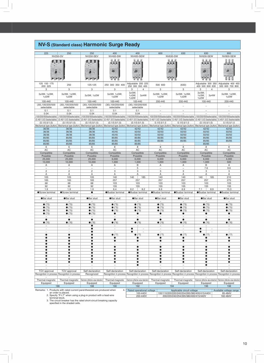
NV-S (Standard class) Harmonic Surge Ready 225 250 250 400 400 600 630 630 800
NV250-SV NV250-SEV NV400-SW NV400-SEW NV630-SW NV630-SEW NV800-SEW
125 150 175200 225 250 125-125 250 300 350 400 Adjustable 200 225
250 300 350 400 500 600 (630) Adjustable 300 350400 500 600 630
Adjustable 400 450 500 600 700 800
3 3 3 3 3 4 3 3 3 4 3
3f3W, 1f3W,1f2W
3f3W, 1f3W,1f2W 3f3W, 1f2W 3f3W, 1f3W,
1f2W
3f3W, 1f3W, 1f2W
3f4W 3f3W, 1f3W,1f2W
3f3W, 1f3W,1f2W
3f3W, 1f3W, 1f2W
3f4W 3f3W, 1f3W,1f2W
100-440 100-440 100-440 100-440 100-440 200-440 200-440 100-440 200-440(30),100/200/500
selectable(30),100/200/500
selectable(30),100/200/500
selectable(30),100/200/500
selectable(30),100/200/500
selectable − − − −
0.1 0.1 0.1 0.1 0.1 − − − −0.04 0.04 0.04 0.04 0.04 − − − −
(100/200/500selectable) (100/200/500selectable) (100/200/500selectable) (100/200/500selectable) (100/200/500selectable) 100/200/500selectable 100/200/500selectable (100/200/500selectable) 100/200/500selectable(0.45/1.0/2.0selectable) (0.45/1.0/2.0selectable) (0.45/1.0/2.0selectable) (0.45/1.0/2.0selectable) (0.45/1.0/2.0selectable) 0.45/1.0/2.0selectable 0.45/1.0/2.0selectable (0.45/1.0/2.0selectable) 0.45/1.0/2.0selectable
(0.1/0.5/1.0) (0.1/0.5/1.0) (0.1/0.5/1.0) (0.1/0.5/1.0) (0.1/0.5/1.0) 0.1/0.5/1.0 0.1/0.5/1.0 (0.1/0.5/1.0) 0.1/0.5/1.0Mechanical type (button) Mechanical type (button) Mechanical type (button) Mechanical type (button) Mechanical type (button) Mechanical type (button) Mechanical type (button) Mechanical type (button) Mechanical type (button)
36/36 36/36 36/36 42/42 42/42 42/42 42/42 42/42 42/4236/36 36/36 36/36 45/45 50/50 50/50 50/50 50/50 50/5036/36 36/36 36/36 45/45 50/50 50/50 50/50 50/50 50/5085/85 85/85 85/85 85/85 85/85 85/85 85/85 85/85 85/8585/85 85/85 85/85 85/85 85/85 85/85 85/85 85/85 85/8585/85 85/85 85/85 85/85 85/85 − − 85/85 −
6 6 6 8 8 8 8 8 8AC AC AC AC AC AC AC AC AC
Compatible Compatible Compatible Compatible Compatible Compatible Compatible Compatible CompatiblePossible Possible Possible Possible Possible Possible Possible Possible Possible25,000 25,000 25,000 6,000 6,000 6,000 6,000 6,000 4,00010,000 10,000 10,000 1,000 1,000 1,000 1,000 1,000 500
A A A A B A A B A− − − − 5 − − 7.6 9.62 2 2 3 3 3 3 3 3A A A A A A A A A
105 105 105 140 140 185 140 140 140 185 210165 165 165 257 257 257 257 257 27568 68 68 103 103 103 103 103 10392 92 92 155 155 155 155 155 1551.9 1.9 1.9 6.4 6.2 8.2 6.9 6.9 7.1 8.9 15.3
�Screw terminal �Screw terminal � �Busbar terminal �Busbar terminal �Busbar terminal �Busbar terminal �Busbar terminal �Busbar terminal− − − − − − − − −
�Bar stud �Bar stud �Bar stud �Bar stud �Bar stud �Bar stud �Bar stud �Bar stud �Bar stud − − − − − − − − −
� (*5) � (*5) � (*5) � (*5) � (*5) � (*5) � (*5) � (*5) � (*5)� (*5) � (*5) � (*5) � (*5) � (*5) � (*5) � (*5) � (*5) � (*5)� (*5) � (*5) � (*5) � (*5) � (*5) � (*5) � (*5) � (*5) � (*5)� (*5) � (*5) � (*5) � � � � � �
− − − − − − − − −� � � � � � � � �
� (*6) � (*6) � (*6) � (*6) � (*6) � (*6) � (*6) � (*6) � (*6)− − � − − − − − −− − � − � − − − � − −− − � − � − − − � − −� � � � (*7) � (*7) � (*7) � (*7) � (*7) � (*7)� � � � � � � � �
� � � � � � � � �
� � � − − − − − −� � � � � � � � �
� � � � � � � � �
� � � � � � � � �
� � � � � � � � �
� � � � � � � � �
� � � � � � � � �
− − − − � − − � −− − − − − − − − −
TÜV approval TÜV approval Self-declaration Self-declaration Self-declaration Self-declaration Self-declaration Self-declaration Self-declarationRecognition in process Recognition in process Recognized Recognition in process Recognition in process Recognition in process Recognition in process Recognition in process Recognition in process
− − − − − − − − −Thermal-magnetic Thermal-magnetic Electronic (effective value detection) Thermal-magnetic Electronic (effective value detection) Thermal-magnetic Thermal-magnetic Electronic (effective value detection) Electronic (effective value detection)
Equipped Equipped Equipped Equipped Equipped Equipped Equipped Equipped Equipped186 188 190 192 194 196 198
Remarks: 1. Products with rated current parenthesized are produced when an order is placed.
2. Specify “P-LT” when using a plug-in product with a lead-wire terminal block.
3. The circuit breaker has the rated short-circuit breaking capacity specifi ed in the shaded cells.
4. Rated operational voltage Applicable circuit voltage Available voltage range100-440V 100/110/200/220/240/254/265/380/400/415/440V 85-484V200-440V 200/220/240/254/265/380/400/415/440V 160-484V
2 Detailed Specifications 2Earth Leakage Circuit Breakers

11
Molded Cage Circuit Breakers — Japan Series1-4
1φ2W 3φ3W1φ2W 1φ2W 3φ3W
1φ2W 1φ2W3φ3W1φ2W1φ3W
2 3 2 3 2 3 2 3 2 3 2 3
2 4 6.3 816
0.3 0.4 0.6 0.81.2 1.4 2 2.54 7.1 8 12 1625 32 45
-1.4 2.5 46.3 7.116 25 3245
AC(V)DC(V)
AC 240VDC 60V
400V230V
DC 60V
415V240V230V
DC 60V
415V200V
DC 65V
200V100V
a 40 60 40 60 50 75 40 60 40 60 50 75bc
ca0.14 0.12 0.16 0.22 0.25 0.37 0.16 0.22 0.18 0.24 0.3 0.43
(LC)(HL)
Small terminal cover (TC-S)Large terminal cover (TC-L)
(RTC)
Notes: *1 If using a 3-pole earth leakage circuit breaker as a 1-pole 2-phase device, *7 UL(cURus) is certified. CCC・TUV is not certified. connect the left and right poles and not the central pole. When wiring to single- *8 UL(cURus) ・CCC・TUV is not certified. phase 3-wire, connect the neutral line to the central pole. *9 only alarm switch(excluding NF30-FAU,NF50-FAU SHT+AL)*2 0.1 for UL1053 *10 Rated current sensitivity 30mA/50mA is available for motor protection rated current*3 Rated shor-circuit breaking capacity of product which is 5A of rated current is 1.5kA.*4 Rated shor-circuit breaking capacity of product which is 5A of rated current is 1.5/1kA .*5 Standard type is SLT equipped.*6 Lead wires come from load side of the breaker as standard. Lead wires come from lateral side of the breaker is also available as an option.
Remarks: (1) breaking capacity of indicate to breaker. (2)
30 50 100
-
5030NF30-FAU NF50-FAU NF50-FHU NF100-FHU
- - - - 30 30 30 50 100
NV30-FAU NV50-FAU NV50-FHU NV100-FHU
Circuit Breakers for control panel(FAU/FHU series)
Rated current In(A)Rated ambient temperture 40℃
10050503010050Molded Case Circuit Breakers Earth Leakage Circuit Breakers(Harmonic Surge Ready)
Frame(A)
3
3 5 10 1520 30 40 50 60 75 100 5 10 15 20
30 40 50
5 10 15 2030 40 50
5 10 15 2030
Phase line(*1)
Number of poles
For motor protection Rated current(*13)
Model
Image
3φ3W1φ2W1φ3W
- - - -
60 75 1005 10 15 2030 40 50
5 10 15 2030
3
- - - -
Rated current sensitivity I△n mA
Earth leakage indication system
High-speed type Max. operating time(s) at 5I△1n(*2)
Pickup current , UL 1053 -
- - - -
75% of I△n 75% of I△n 75% of I△n- - - 75% of I△n0.04 0.04 0.04 0.04
Mechanical type(button) Mechanical type(button) Mechanical type(button) Mechanical type(button)
GB 14048.2(Icu/Ics)
IEC 60947-2EN 60947-2
(Icu/Ics)
UL1077CSA C22.2
No.235
Rat
ed s
hort-
circ
uit
Bre
akng
Cap
aciti
es(k
A)
240 24060 60
2.5(*3)2.5(*3)
Rated insullation voltage(V)
AC
AC
Rated voltageAC(V)Jis C 8201-2-2Ann.1 Ann.2
(Icu/Ics
Jis C 8201-2-1Ann.1 Ann.2
(Icu/Ics)
Rated voltage
AC
Rated insullation voltage(V)
Rated insullation voltage(V)
AC
- - - - - -240 240 240 240 240 240
500 500 AC230V(rated voltage) AC230V(rated voltage) AC240V(rated voltage) AC240V(rated voltage)
5 5
250- - - - - -
250
51.5 1.5
5 2.5(*3) 2.5(*3)
- -2.5/1(*4) 2.5/1(*4) 5/2 5/2 - - 5/2 5/2
- - 1.5/1 - - -
- -250 250 500 500 AC230V(rated voltage) AC230V(rated voltage) AC240V(rated voltage) AC240V(rated voltage)
1.5/1 1.5/1 - - - -
- -- - 5/2 5/2 - - 5/2 5/2- - 1.5/1 - - -
- -1.5/1 1.5/1 - - - - - -
2.5/1(*4) 2.5/1(*4) - - 2.5/1(*4) 2.5/1(*4)
- -- - 1.5/1 - - - - -
250 250 500 500 - -
- -1.5/1 1.5/1 - - - - - -
2.5/1(*4) 2.5/1(*4) 5/2 5/2 - -
100-200 100-200- - - - 2.5/1(*4) 2.5/1(*4) 5/2 5/2- - - - 100-200 100-200
5/2 5/2Rated impluse withstand voltage Uimp(kV) 2.5 2.5 4 4 2.5 2.5 4
- - - - 2.5/1(*4) 2.5/1(*4)4
Current AC/DC compatible AC/DC compatible AC AC AC AC AC AC- - -
Ove
rall
dim
entio
ns(
mm
)
7597.56076
Suitability for isolation - - - - -
76 7657 57 60 57 57 60
75
Screw terminal Screw terminal Screw terminal Screw terminal Screw terminal Screw terminal
Mass kg 0.51 0.57
Screw terminal Screw terminal● ● ● ● ● ● ● ●Installation
Reverse connection - - - - - -
6073.5 73.5 76 73.5 73.5
72 72 96 72 72 96 97.5
- -
● ●
● ●
● ●
Alarm switch(AL)Auxiliary switch(AX)
Shunt trip(SHT)- -
● ●
● ●
●(*5) ●(*6)●(*5) ●(*6)●(*5) ●(*6)
●(*8) ●(*8)
●
--
●(*5) ●(*6)●(*5) ●(*6)
- -
●(*8)- -
- -
●
● ●
- -
● ●
- -
● ● ● ●● ●
- -
●(*8) ●(*8)
TUV approvalCE marking TUV approval TUV approval TUV approval TUV approval TUV approval●
-
● ●
-Front plate connection terminal cover
Ext
erm
inal
acc
esso
ries
●(*7) ●(*7)●(*7) ●(*7)
●
●(*8) ●(*8)- -
●(*7)
Recognized Recognized Recognized Recognized Recognized Recognized
Connection
TUV approval TUV approval
●(*7)●(*7) ●(*7)
● ●
●(*8) ●(*8)●(*8) ●(*8)
● ●
●(*8)
Handle lock devise
Test lead wire(TBL)Optional accessories
- - -
With lead-wire terminal block(SLT)
Front connectionIEC 35mm rail
Trip button -(*9) -(*9) -(*9) -(*9) -
RecognizedAutomatic tripping device Termal-magnetic Termal-magnetic Termal-magnetic Termal-magneticHydrautic magnetic Hydrautic magnetic Hydrautic magnetic Hydrautic magnetic
CCC recognition Recognized

12
2 3 2 3 2 3 2 3 2 3 2 3 2 3
690V500V440V415V400V380V230V200V250V125V415V400V380V230V250V125V
a 36 54 36 54 36 54 36 54 36 54
b
c
ca
0.3 0.4 0.3 0.4 0.3 0.4 0.3 0.4 0.3 0.4 0.75 0.85 0.75 0.85
Remarks: (1) breaking capacity of indicate to breaker. (2)Producs with rated current parenthesized are produced when an order is placed.
Recognized RecognizedTUV approval
cass
ete
type
-ac
cess
sorie
s
Auxiliary switch(AX)Alarm switch(AL)
Shunt trip(SHT)Undervoltage trip(UVT)With lead-wire terminal block(SLT)
Recognized RecognizedCE marking TUV approval TUV approval TUV approval TUV approval
- - - -
●
- -Marine use approval(NK, LR, ABS, GL) - - - - -
Rear stud(B-ST)
IEC 35mm rail mounting adaptersPlug-in (PM)
Ext
erna
l a
cces
sorie
s
Enclosure
Electrical operation device(NFM)Mechanicalinterlock(MI)
Panel mountingBreaker mounting
Handle lockdevice
TUV approval TUV approvalCCC recognition Recognized Recognized Recognized
Rat
ed s
hort-
circ
uit
Bre
akng
Cap
aciti
es(k
A)
GB 14048.2(Icu/Ics)
Utilization categoryPollution degree
EMC environment condition(environment A or B)
Number of operating cycles
Without currentWith current(440VAC)
AC
DC(*2)
JIS C 8201-2-1 Ann.1JIS C 8201-2-1 Ann.2
IEC 60947-2EN 60947-2
(Icu/Ics)
AC
DC(*2)
Rated impluse withstand voltage Uimp(kV)
Termal-magneticTrip button equipped equipped equipped equipped equipped equipped equipped
Automatic tripping device Termal-magnetic Termal-magnetic Termal-magnetic Termal-magnetic Termal-magnetic Termal-magnetic
-- -
- - - - - -
● ●
- - - -● ● ● ●
- - -
●(*3)
● ● ● ● ● ●(*3) ●(*3)
●(*3) ●(*3)
●(*3) ●(*3) ●(*3) ●(*3) ●(*3) ●(*3)
●(*3)
●(*3)
●(*3) ●(*3) ●(*3) ●(*3)
●(*3) ●(*3) ●(*3) ●(*3)
Mass of front-face type kg
● ● ● ●
68
90 90 90 90 90 90 90
Front connection(F)
Inst
alla
tion
and
conn
ectio
n
Solderless(BOX) terminal(SL)
Rear(B)
Plug-in(PM)
68 68 68 68 68 68
● ● ●
N/A N/A N/A N/A N/A N/A
100 130 130
Reverse connection - - - - - Possible Possible
Ove
rall
dim
entio
ns(m
m) 75
3
100 100 100 100
3 3 3 3 3 3
75
N/A
AC/DC compatible AC/DC compatible AC/DC compatible
Suitability for isolation compatible compatible compatible compatible compatibleCurrent(*1) AC/DC compatible AC/DC compatible AC/DC compatible AC/DC compatible
compatible compatible
A AA A A A A
15,000 15,0006,000 6,000 6,000 6,000 6,000 8,000 8,00010,000 10,000 10,000 10,00010,000
25/25 25/257.5/7.5 7.5/7.5 15/15 15/15 15/15 50/50 50/50
5/5 5/5 10/8 10/8 10/8
25/255/5 5/5 10/8 10/8 10/8 25/25 25/255/5 5/5 10/8 10/8 10/8 25/25
50/50 50/507.5/7.5 7.5/7.5 15/15 15/15 15/15
25/257.5/7.5 7.5/7.5 15/15 15/15 15/15 50/50 50/50
25/25 25/255/5 5/5 10/8 10/8 10/8 25/25
25/25 25/255/5 5/5 10/8 10/8 10/85/5 5/5 10/8 10/8 10/8
- - - -
63 15 20 30 40 5060 75 100 125
10/102.5/2.5 2.5/2.5 7.5/6 7.5/6 7.5/6 20/20 20/20
- - -- - - - - 10/10
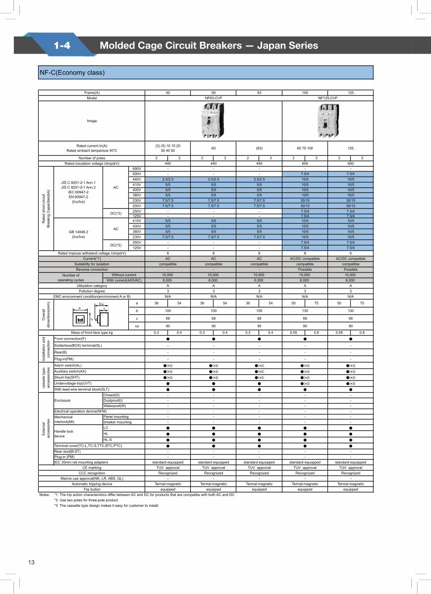
Number of polesRated insulation voltage Uimp(kV) 440 440 440 440 440 600 600
Rated current In(A)Rated ambient temperture 40℃ 3 5 10 15 20 30 32 (3) (5) 10 15 20
30 40 50 60
Model NF32-SVF NF63-SVF NF125-SVF
Image
NF-S(Standard class)
Frame(A) 30 32 50 60 63 100 125
standard equopped standard equopped standard equopped standard equopped standard equopped standard equopped standard equopped
-- - - - - - -- - - - - -
●
● ● ● ● ●Terminal cover(TC-L,TC-S,TTC,BTC,PTC)● ● ● ● ●
LCHLHL-S
● ●
- - - - - - -
● ●
●
● ● ● ● ● ● ●
● ● ● ● ●
Waterpoof(W)Dustproof(I)
- - - - -
-- - - - - - -- -
Closed(S)
- - - - - - -
- -
- - - - - - -
- - - - -
●(*3) ●(*3)
- - - -10/10 15/15 15/1510/10 10/10 10/10 10/10
6 6 6 6 6 8 8
-10/10 10/10 10/10 10/10 10/10 15/15 15/15
- - - - - -
- - -
13
1-4 Molded Cage Circuit Breakers — Japan Series
2 3 2 3 2 3 2 3 2 3
690V500V440V415V400V380V230V200V250V125V415V400V380V230V250V125V
a 36 54 36 54 36 54 50 75 50 75
b
c
ca
0.3 0.4 0.3 0.4 0.3 0.4 0.55 0.8 0.55 0.8
Notes: *1 The trip action characteristics differ between AC and DC for products that are compatibe with both AC and DC*2 Use two poles for three-pole product.*3 The cassette type design makes it easy for customer to install.
NF-C(Economy class)
NF63-CVF NF125-CVF
Trip button equipped equipped equipped equipped equippedAutomatic tripping device Termal-magnetic Termal-magnetic Termal-magnetic Termal-magnetic Termal-magnetic
Marine use approval(NK, LR, ABS, GL) - - - - -CCC recognition Recognized Recognized Recognized Recognized Recognized
CE marking TUV approval TUV approval TUV approval TUV approval TUV approvalIEC 35mm rail mounting adapters standard equopped standard equopped standard equopped standard equopped standard equoppedPlug-in (PM) - - - - -Rear stud(B-ST) - - - - -Terminal cover(TC-L,TC-S,TTC,BTC,PTC) ● ● ● ● ●
● ● ● ●
HL ● ● ● ● ●
- -
Handle lockdevice
LC ● ● ● ● ●
-breaker mounting - - - - -
Mechanicalinterlock(MI)
Panel mounting - - - -
HL-S ●
Dustproof(I) - - - - -
Ext
erna
l a
cces
sorie
s
EnclosureClosed(S) - - - - -
Electrical operation device(NFM) - - - - -Waterpoof(W) - - -
●(*3)
With lead-wire terminal block(SLT) ● ● ● ● ●
Shunt trip(SHT) ●(*3) ●(*3) ●(*3) ●(*3) ●(*3)
cass
ete
type
-ac
cess
sorie
s
Alarm switch(AL) ●(*3) ●(*3) ●(*3) ●(*3)
Undervoltage trip(UVT) ● ● ● ●(*3)
- -
●(*3)
Auxiliary switch(AX) ●(*3) ●(*3) ●(*3) ●(*3) ●(*3)
Solderless(BOX) terminal(SL) - - - - -
Mass of front-face type kg
Inst
alla
tion
and
conn
ectio
n
Front connection(F) ● ● ● ● ●
Plug-in(PM) - - - - -
Rear(B) - - -
Ove
rall
dim
entio
ns(m
m)
100 100 100 130 130
EMC environment condition(environment A or B) N/A N/A N/A N/A N/A
90 90 90 90 90
68 68 68 68 68
Pollution degree 3 3 3 3 3Utilization category A A A A A
10,000With current(440VAC) 6,000 6,000 6,000 6,000 6,000
Number of operating cycles
Without current 10,000 10,000 10,000 10,000Reverse connection - - - Possible Possible
Suitability for isolation compatible compatible compatible compatible compatible
DC(*2)- - - 7.5/4 7.5/4
Current(*1) AC AC AC AC/DC compatible AC/DC compatibleRated impluse withstand voltage Uimp(kV) 6 6 6 8 6
GB 14048.2(Icu/Ics)
AC
- - -
5/5 5/5 5/5 10/5
5/5 5/5 5/5 10/5
7.5/47.5/4
- - - 7.5/4 7.5/4DC(*2) - - - 7.5/4 7.5/4
10/57.5/7.5 7.5/7.5 7.5/7.5 10/5 10/5
10/55/5 5/5 5/5 10/5 10/5
7.5/7.5 7.5/7.5 7.5/7.5 30/15 30/157.5/7.5 7.5/7.5 7.5/7.5 30/15 30/15
5/5 5/5 5/5 10/5 10/55/5 5/5 5/5 10/5 10/5
-- - - 7.5/4 7.5/4
600
Rat
ed s
hort-
circ
uit
Bre
akng
Cap
aciti
es(k
A)
JIS C 8201-2-1 Ann.1JIS C 8201-2-1 Ann.2
IEC 60947-2EN 60947-2
(Icu/Ics)
AC
- - - -
5/5 5/5 5/5 10/5 10/52.5/2.5 2.5/2.5 2.5/2.5 10/5 10/5
Number of polesRated insulation voltage Uimp(kV) 440 440 440 600
Rated current In(A)Rated ambient temperture 40℃
(3) (5) 10 15 2030 40 50 60 (63) 60 75 100 125
Model
Image
Frame(A) 50 60 63 100 125
14
100 125
15 20 30 (40) 5060 75 100 125
2 3 2 3 2 3 2 3 2 3 3 3
1φ2W 1φ2W,3φ3W1φ3W 1φ2W 1φ2W,3φ3W
1φ3W 1φ2W 1φ2W,3φ3W1φ3W 1φ2W 1φ2W,3φ3W
1φ3W 1φ2W 1φ2W,3φ3W1φ3W
1φ2W,3φ3W1φ3W
1φ2W,3φ3W1φ3W
AC 100-240 100-440 100-240 100-440 100-240 100-440 100-240 100-440 100-240 100-440 100-440 100-440
(mA) 30 30 100(200) (500) 30 30 100
(200) (500) 30 30 100(200) (500) 30 30 100
(200) (500) 30 30 100(200) (500)
30,100/200/500selectable
30,100/200/500selectable
at L△n 0.1 0.1
at 5l△n 0.04 0.04
(mA) (100/200/500) selectable
(100/200/500) selectable
(*4) (0.45/10./2.0 selectable)
(0.45/10./2.0 selectable)
(0.1/0.5/1.0) (0.1/0.5/1.0)Mechanical type
(button)Mechanical type
(button)440V - 2.5/2.5 - 2.5/2.5 - 7.5/6 - 7.5/6 - 7.5/6 20/20 20/20415V - 5/5 - 5/5 - 10/8 - 10/8 - 10/8 25/25 25/25400V - 5/5 - 5/5 - 10/8 - 10/8 - 10/8 25/25 25/25230V 50/50 50/50200V 50/50 50/50100V 7.5/7.5 7.5/7.5 7.5/7.5 7.5/7.5 15/15 15/15 15/15 15/15 15/15 15/15 50/50 50/50415V - 5/5 - 5/5 - 10/8 - 10/8 - 10/8 25/25 25/25400V - 5/5 - 5/5 - 10/8 - 10/8 - 10/8 25/25 25/25380V - 5/5 - 5/5 - 10/8 - 10/8 - 10/8 25/25 25/25230V 50/50 50/50
4 6 4 6 4 6 4 6 4 6 6 6AC AC
compatible compatiblepossible possible10,000 10,000
6,000(AC240V) 6,000 6,000(AC240V) 6,000 6,000(AC240V) 6,000 6,000(AC240V) 6,000 6,000(AC240V) 6,000 8,000 8,000A A2 2A A
a 36 54 36 54 36 54 36 54 36 54 75 75
b 130 130
c 68 68
ca 90 90
0.4 0.5 0.4 0.5 0.4 0.5 0.4 0.5 0.4 0.5 0.95 0.95
● ●
- -
- -
- -
- ●(*6) - ●(*6) - ●(*6) - ●(*6) - ●(*6) ●(*6) ●(*6)- ●(*6) - ●(*6) - ●(*6) - ●(*6) - ●(*6) ●(*6) ●(*6)- ●(*6) - ●(*6) - ●(*6) - ●(*6) - ●(*6) ●(*6) ●(*6)- ● - ● - ● - ● - ● ●(*6) ●
- -- ● - ● - ● - ● - ● ● ●
Test button module(TBM) ●(*7) ●(*7)- -- -- -- -- -- -
● ●
● ●
● ●
● ●
- -- -
standard equipped standard equippedTUV approval TUV approval
Recognized Recognized- -
Termal-magnetic Termal-magneticequipped equipped
Notes: *1 If using a 3-pole earth leakage circuit breaker as a 1-pole 2-phase device, *5 breaking capacity of 2P AC240V is same as 230V. connect the left and right poles and not the central pole. When wiring to single- *6 The cassette type design makes it easy for customer to install. phase 3-wire, connect the neutral line to the central pole. *7 Standard type is SLT equipped.*2 In case of time delay type, rated voltage is 200-440V.*3 In case of time delay tyoe, products can be produced more than 20A of rated current.*4 When the operating time are 0.45, 1.0 and 2.0 seconds, the Earth leakage circuit breaker operates between 0.15 and 0.45 seconds, between 0.6 and 1.0 seconds and between 1.2 and 2.0 seconds respectively.
standard equoppedTUV approval
Recognized-
Termal-magneticequipped
●
●
●
●
--
----
●
-
-
-
-
●(*7)
68
90
15/15
ACcompatible
-10,000
--
A
Visible color(Indication window)
15/1515/15
15/1515/15
2A
100
-
-
-
-
●(*7)
-
TUV approvalRecognized
-
-
2A
100
68
90
●
15/15
ACcompatible
-10,000
A
-
-
0.10.04
-
NV63-SVF
-
-Visible color
(Indication window)
Termal-magneticequipped
(63)
0.10.04
●
●
●
--
standard equopped
-----
●
Automatic tripping device Termal-magnetic Termal-magnetic Termal-magneticTrip button equipped equipped equipped
CCC recognition Recognized Recognized RecognizedMarine use approval(NK, LR, ABS, GL) - - -
IEC 35mm rail mounting adapters standard equopped standard equopped standard equoppedCE marking TUV approval TUV approval TUV approval
Rear stud(B-ST) - - -Plug-in (PM) - - -
- - -
● ● ●
Terminal cover(TC-L,TC-S,TTC,BTC,PTC) ● ● ●
Handle lockdevice
LC ● ● ●
HL ● ● ●
HL-S
Waterpoof(W) - - -Electrical operation device(NFM) - - -
Ext
erna
l a
cces
sorie
s
EnclosureClosed(S) - - -Dustproof(I) - - -
Mechanicalinterlock(MI)
Panel mounting - - -breaker mounting
- - -With lead-wire terminal block(SLT)
●(*7) ●(*7) ●(*7)
cass
ete
type
-ac
cess
sorie
s
Alarm switch(AL)Auxiliary switch(AX)Shunt trip(SHT)Undervoltage trip(UVT)Earth leakage alarm switch(EAL)
- - -
Plug-in(PM) - - -Inst
alla
tion
and
conn
ectio
n
Front connection(F) ● ● ●
Solderless(BOX) terminal(SL) - - -
Rear(B)
68 68
90 90 90
Mass of front-face type kg
EMC environment condition(environment A or B) A A A
Ove
rall
dim
entio
ns(m
m)
100 100 100
68
Utilization category A A APollution degree 2 2 2
Reverse connection(below 230VAC) - - -Number of
operating cyclesWithout current 10,000 10,000 10,000
With current(440VAC)
Rated impluse withstand voltage Uimp(kV)Current AC AC AC
Suitability for isolation compatible compatible compatible
GB 14048.2Icu/Ics) (*8) AC
7.5/7.5 7.5/7.5 15/15
Rat
ed s
hort-
circ
uit
Bre
akng
Cap
aciti
es(k
A) JIS C 8201-2-1 Ann.1
JIS C 8201-2-1 Ann.2IEC 60947-2 2nd.ed
(Icu/Ics) (*5)
AC7.5/7.5 7.5/7.5 15/157.5/7.5 7.5/7.5 15/15
- - -
Earth leakage indication system Visible color(Indication window)
Visible color(Indication window)
Visible color(Indication window)
Tim
e-de
lay
Type
Rated current sensitivity - - -
Max. operating tme(s) - - -
Internal non-operating(s) (or more)
0.1 0.1 0.10.04 0.04 0.04
Number of poles
Phase line(*1)
Rated operational voltage Ue(V) (*2)
Hig
h-sp
eed
Type
Rated current sensitivity
Max. operating tme(s)
Image
Rated current In(A)Rated ambient temperture 40℃ (5) (10) 15 20 30 (32) (5) (10) 15 20 30
45 50
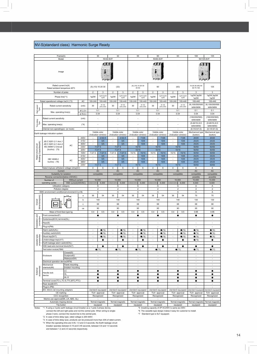
NV-S(standard class) Harmonic Surge Ready
Frame(A) 30 32 50Model NV125-SVFNV32-SVF
60
60
63

15
1-4 Molded Cage Circuit Breakers — Japan Series
100 125
60 75 100 125
2 3 2 3 2 3 3 3
1φ2W 1φ2W,3φ3W1φ3W 1φ2W 1φ2W,3φ3W
1φ3W 1φ2W 1φ2W,3φ3W1φ3W
1φ2W,3φ3W1φ3W
1φ2W,3φ3W1φ3W
AC 100-240 100-440 100-240 100-440 100-240 100-440 100-440 100-440
(mA) 30 30 100(200) (500) 30 30 100
(200) (500) 30 30 100(200) (500)
30,100/200/500selectable
30,100/200/500selectable
at L△n 0.1 0.1at 5l△n 0.04 0.04
(mA) (100/200/500) selectable (100/200/500) selectable(*4) (0.45/10./2.0 selectable) (0.45/10./2.0 selectable)
(0.1/0.5/1.0) (0.1/0.5/1.0)Mechanical type
(button)Mechanical type
(button)440V - 2.5/2.5 - 2.5/2.5 - 2.5/2.5 10/5 10/5415V - 5/5 - 5/5 - 5/5 10/5 10/5400V - 5/5 - 5/5 - 5/5 10/5 10/5230V 30/15 30/15200V 30/15 30/15100V 30/15 30/15415V - 5/5 - 5/5 - 5/5 10/5 10/5400V - 5/5 - 5/5 - 5/5 10/5 10/5380V - 5/5 - 5/5 - 5/5 10/5 10/5230V 30/15 30/15
4 6 4 6 4 6 6 6AC AC
compatible compatiblepossible possible10,000 10,000
6,000(AC240V) 6,000 6,000(AC240V) 6,000 6,000(AC240V) 6,000 6,000 6,000A A2 2A A
a 36 54 36 54 36 54 75 75
b 130 130
c 68 68
ca 90 90
0.4 0.5 0.4 0.5 0.4 0.5 0.9 0.9
● ●
- -
- -
- -
- ●(*6) - ●(*6) - ●(*6) ●(*6) ●(*6)- ●(*6) - ●(*6) - ●(*6) ●(*6) ●(*6)- ●(*6) - ●(*6) - ●(*6) ●(*6) ●(*6)- ● - ● - ● ●(*6) ●(*6)
- -- ● - ● - ● ● ●
Test button module(TBM) ●(*7) ●(*7)- -- -- -- -- -- -
● ●
● ●
● ●
● ●
- -- -
standard equipped standard equippedTUV approval TUV approval
Recognized Recognized- -
Termal-magnetic Termal-magneticequipped equipped
Notes: *1 If using a 3-pole earth leakage circuit breaker as a 1-pole 2-phase device, *7 Standard type is SLT equipped. connect the left and right poles and not the central pole. When wiring to single- phase 3-wire, connect the neutral line to the central pole.*2 In case of time delay type, rated voltage is 200-440V.*3 In case of time delay tyoe, products can be produced more than 20A of rated current.*4 When the operating time are 0.45, 1.0 and 2.0 seconds, the Earth leakage circuit breaker operates between 0.15 and 0.45 seconds, between 0.6 and 1.0 seconds and between 1.2 and 2.0 seconds respectively.*5 breaking capacity of 2P AC240V is same as 230V.*6 The cassette type design makes it easy for customer to install.
- -
●(*7)
Visible color(Indication window)
Visible color(Indication window)
Visible color(Indication window)
Plug-in(PM) - - -
- - -
Rear(B) - -
Earth leakage indication system
-
Inst
alla
tion
and
conn
ectio
n
Front connection(F) ● ● ●
-
Trip button equipped
CCC recognition Recognized
Plug-in (PM) -
HL ●
breaker mounting -
Dustproof(I) -
With lead-wire terminal block(SLT)
Undervoltage trip(UVT)
Auxiliary switch(AX)Alarm switch(AL)
Shunt trip(SHT)
Earth leakage alarm switch(EAL)
cass
ete
type
-ac
cess
sorie
s
Mass of front-face type kg
-
equipped equippedAutomatic tripping device Termal-magnetic Termal-magnetic Termal-magnetic
Marine use approval(NK, LR, ABS, GL) - - -Recognized Recognized
CE marking TUV approval TUV approval TUV approvalIEC 35mm rail mounting adapters standard equopped standard equopped standard equopped
- -Rear stud(B-ST) - - -Terminal cover(TC-L,TC-S,TTC,BTC,PTC) ● ● ●
-
● ●Handle lockdevice
LC ● ● ●
HL-S ● ● ●
- -
●(*7) ●(*7)
Ext
erna
l a
cces
sorie
s
EnclosureClosed(S) - - -
Waterpoof(W) - - -
- -Mechanicalinterlock(MI)
Panel mounting - - -Electrical operation device(NFM) - -
Solderless(BOX) terminal(SL)
68 68 68Ove
rall
dim
entio
ns(m
m)
100 100 100
90 90 90
EMC environment condition(environment A or B) A A APollution degree 2 2 2
Utilization category A A AWith current(440VAC)
Number of operating cycles
Without current 10,000 10,000 10,000Reverse connection(below 230VAC) - - -
Suitability for isolation compatible compatible compatibleCurrent AC AC AC
Rated impluse withstand voltage Uimp(kV)
Rat
ed s
hort-
circ
uit
Bre
akng
Cap
aciti
es(k
A)
GB 14048.2Icu/Ics) (*8) AC
7.5/7.5 7.5/7.5 7.5/7.5
7.5/7.5 7.5/7.5 7.5/7.5
7.5/7.5 7.5/7.5 7.5/7.57.5/7.5 7.5/7.5 7.5/7.5
JIS C 8201-2-1 Ann.1JIS C 8201-2-1 Ann.2IEC 60947-2 2nd.ed
(Icu/Ics) (*5)
AC
NV125-CVF
Image
NV-C(Economy class) Harmonic Surge Ready
Frame(A) 50 60 63
Number of poles
Phase line(*1)
Rated current In(A)Rated ambient temperture 40℃ (5) (10) 15 20 30 40 50 60 (63)
Model NV63-CVF
-------Rated current sensitivity
Rated operational voltage Ue(V) (*2)
Hig
h-sp
eed
Type
Tim
e-de
lay
Type
0.040.040.04Max. operating tme(s)
Rated current sensitivity
0.1 0.1 0.1
Max. operating tme(s)Internal non-operating(s) (or more)
-

16
(0.5) (1) (1.5)(2) (3) 4 5(6) (7) (8) 1013 15 20 2530 (35) 40 50
1 2 3 2 3 2 3 2 3 2 3AC(V)DC(V) 60
600/Y/347V480V
480Y/277V240V 5120V 10
DC 60V 10
690V500V440V415V400V -380V230V 10/7.5250V125V 10/7.5
AC/DC
a 18 36 54 36 54 50 75 50 75 50 75
b
c
ca
0.15 0.3 0.45 0.3 0.45 0.55 0.8 0.5 0.75 0.55 0.8
Screw terminal(AMP/N)
Solderless terminal(SL)
Bar(BAR)
HLHL-S
Notes: *1 The trip action characteristics differ between AC and DC for products that are compatibe with both AC and DC*2 The standard structure conforms to IP20(finger protection)*3 Rated ambient temperature for NF50-SVFU, NF100-CVFU, NF100-SRU, NF100-HRU is specified at 40℃ also by IEC*4 The circuit breaker with busbar teeminal have insullation barriers.*5 Isolation function is not available.*6 Circuit breaker for power supply solderless load screw terminal(SL/AMP-N) are available. In this case , a busbar terminal is not provided on the load side.*7 breaking capacity of ( ) is for below 15A of rated current.*8 optional parts.*9 These cassette type circuit breaker can be installed by the customer. They can be installed with their side faces in close contact(except NF50-SVFU and UVT)
UL 489CSA C22.2 No.5-02
JIS C 8201-2-1 Ann.1IEC 60947-2EN60947-2
(Icu/Ics)
Hnadle lock device
Large terminal cover(TC-L)
- -35/18(25/13) (*7) 50/25(25/13) (*7)
-
AC
10/510/5
-10/7.5
-10/7.5 15/8
10/515/8
50(25) (*9)
-
10/510/5
Ratedvoltage -
AC
-10 14
18/9(10/5) (*7)- 7.5/4 10/5 15/8 25/13(15/8) (*7)
500- - - -
Rated insulation voltageUi(V)
-- - - -
14
Trip button - equipped equipped equipped equippedAutomatic tripping device Termal-magnetic Termal-magnetic Termal-magnetic Termal-magnetic Termal-magnetic
Recognized RecognizedCE marking TUV approval TUV approval TUV approval TUV approval TUV approval
IEC 35mm rail mounting adapters - - - - -
CCC recognition Recognized Recognized Recognized
Ext
erm
nal
acc
esso
ries
Small terminal cover(TC-S) - - - - -
- ● ● ● ●
● ● ● ● ●
● ● ● ● ●
●(*4,6) ●(*6) ●(*6)
-
●(*9) ●(*9)With lead-wire terminal block(SLT) - ● ● ● ●
Shunt trip(SHT) ●(*8) ●(*9) ●(*9) ●(*9) ●(*9)
●(*9)Auxiliary switch(AX) ●(*8) ●(*9) ●(*9) ●(*9) ●(*9)
cass
ete
type
-ac
cess
sorie
s
Alarm switch(AL) ●(*8) ●(*9) ●(*9) ●(*9)
Undervoltage trip(UVT) - ● ●(*9)
Mass of front-face type kg
Inst
alla
tion
and
conn
ectio
n ● ● ● ● ●
70 90 90 96 102
- ●(*4) ● ●
- - ● ● ●
Fron
t(F)
- -
44 68 68 68 74Ove
rall
dim
entio
ns(m
m)
124 120 150 120 120
EMC environment condition(environment A or B) N/A N/A N/A N/A N/APollution degree 3 3 3 3 3
Utilization category A A A A A
10,000With current(440VAC) 6,000 6,000 6,000 6,000 6,000
Number of operating cycles
Without current 10,000 10,000 10,000 10,000Reverse connection possible - possible possible possible
Suitability for isolation compatible compatible compatible compatible compatible
-
10/5
DC(*2)
- - - - -
Current(*1) AC AC AC ACRated impluse withstand voltage Uimp(kV) 6 6 8 8 8
AC 25/13(15/8) (*7)25/13(15/8) (*7)
15/815/8
35(25) (*9)
-440 440 600 500
-
480- - - -
- - - - -- - - - 18(10) (*9)
- - -
- - 7.5/4 10/5
- - -
UL 489 Listed Mold Case Circuit Breakers
Frame(A)NF50-SMU NF50-SVFU
50 100NF100-CVFU NF100-SRU NF100-HRU
Power supply solderless load bar(SL/BAR)
(1) (2) 3 5 10 15 20 (25) 3040 50 60 (70) 75 (80) (90)
100
Model
Image
0.5 1 (1.5) 2 3 4 5(6) 7 (8) 10 13 15 20(25) 30 (35) (40) 50
Rat
ed s
hort-
circ
uit
Bre
akng
Cap
aciti
es(k
A)
240 240 240 240Number of poles
Rated current In(A)Rated ambient temperture 40℃(IEC 30℃) (*3)
(3) 5 10 1520 30 40 50
60 (70) 75(80) (90) 100
(1) (2) 3 5 10 15 20 (25) 3040 50 60 (70) 75 (80) (90)
100
- - - -

17
1-4 Molded Cage Circuit Breakers — Japan Series
NV100-CVFU NV100-HRU
60 (70) 75(80) (90) 100
5 10 15 20(25) 30 40 50
5 10 15 20 (25) 30 40 50
60 (70) 75 (80) (90) 100
5 10 15 20 (25) 30 40 5060 (75) (80) (90) 100
2 3 3 2 3 31φ2W 1φ2W,3φ3W 1φ2W,3φ3W 1φ2W 1φ2W,3φ3W 1φ2W,3φ3W
120-240 120-240-480
100-240 100-440 100-440 100-230-400-440
(mA) 30 50 30 50 10030 100
100・200・500selecable
30 5030 50
100・300・500selecable
30,100/200/500selectable
75% of l△n 75% of l△n
0.04 0.04
Mechanical type(button)
Mechanical type(button)
480V - 18(10) (*5)240V 14 50(25) (*5)120V 14 50(25) (*5)440V - 7.5/4 10/5 25/13(15/8) (*5)400V - 10/5 10/5 25/13(15/8) (*5)230V 15/8(*10) 15/8 15/8 50/25(25/13) (*5)100V 15/8 15/8 15/8 50/25(25/13) (*5)415V - 10/5 10/5 25/13(15/8) (*5)380V - 10/5 10/5 25/13(15/8) (*5)230V 15/8 50/25(25/13) (*5) (*8)
4 6 6 8compatible compatible
possible - possible possibleA A2 2A A
a 36 54 75 50 75 75
b 150 120
c 68 74
ca 90 102
0.4 0.5 0.9 0.55 0.85 0.95
● ●
● ●
●(*4) ●
●(4,6) ●(*6)- ●(*9) ●(*9) ●(*9)
- ●(*9) ●(*9) ●(*9)
- ●(*9) ●(*9) ●(*9)
- ● ●(*9) ●(*9)
- ● ● ●
●(*11) -
● ●
● ●
● ●
-(*2) ●(*2)standard equipped standard equipped
TUV approval TUV approvalRecognized Recognized
Termal-magnetic Termal-magneticequipped equipped
Notes: *1 If using a 3-pole earth leakage circuit breaker as a 1-pole 2-phase device, connect the left and right poles and not the central pole.*2 The standard structure conforms to IP20(finger protection)*3 0.1 for UL 1053.*4 The circuit breaker with busbar teeminal have insullation barriers.*5 breaking capacity of ( ) is for below 15A of rated current.*6 Circuit breaker for power supply solderless load screw terminal(SL/AMP-N) are available. In this case , a busbar terminal is not provided on the load side.*7 In case AC100V , not comply CCC recognition*8 In case AC 100V , comply CCC recognition.*9 These cassette type circuit breaker can be installed by the customer. They can be installed with their side faces in close contact(except NV50-SVFU and UVT)*10 breaking capacity of JIS C 8201-2 Ann.1 AC240V is same as 230V*11 Standard type is SLT equipped.* 12 Isolation function is not available and no TUV approval.
Rated current In(A)Rated ambient temperture 40℃
(5) (10) 15 20 30 40 50
UL 489 Listed Earth Leakage Circuit Breakers(Harmonic Surge Ready)
Frame(A) 50Model NV50-SVFU
Number of polesPhase line(*1)
Hig
h-sp
eed
Type
Rated voltage AC V
UL 489IEC 60947-2EN 60947-2
JIS C 8201-2-2 Ann1
Max. operating tme(s) at 5l△n (*4)
Image
Earth leakage indication system Visible color(Indication window)
120-240
Rated current sensitivity L△n
Mechanical type(button)
AC14
- -
75% of l△n 75% of l△n
0.04 0.04
Pickup current, UL 1053
35/18(25/13) (*5)
AC15/8 35/18(25/13) (*5)(*8)
AC
Rat
ed s
hort-
circ
uit
Bre
akng
Cap
aciti
es(k
A)
-
35/18(25/13) (*5)
14 35(25) (*5)
GB 14048.2Icu/Ics) (*7)
JIS C 8201-2-2 Ann.1IEC 60947-2EN 60947-2
(Icu/Ics)
UL 489CSA C22.2 No.5-02
-
--
●
●(*11) -cass
ete
type
-acc
esss
orie
s
Auxiliary switch(AX)
Alarm switch(AL)
Test button module(TBM)
With lead-wire terminal block(SLT)
Undervoltage trip(UVT)
Shunt trip(SHT)
CE marking TUV approval TUV approvalstandard equipped standard equipped
● ●
-(*2) ●(*2)Ext
erna
l a
cces
sorie
s Hnadle lock device
Large terminal cover(TC-L)Small terminal cover(TC-S)IEC 35mm rail mounting adapters
HL ● ●
HL-S ● ●
Automatic tripping device Termal-magnetic Hydrautic magneticTrip button equipped equipped
CCC recognition Recognized Recognized
120-240
100-230
100NV100-SRU
35(25) (*5)
●(*9)
●(*9)
●(*9)
- ●
- ●(*6)
● ●
- ●
68
90 96
A A
120 120
●(*9)
8
Fron
t(F)
Screw terminal(AMP/N)
Solderless terminal(SL)
Bar(BAR)
Mass of front-face type kg
EMC environment condition(environment A or B)
Ove
rall
dim
entio
ns(m
m)
68
Utilization category A APollution degree
Power supply solderless load bar(SL/BAR)Inst
alla
tion
and
conn
ectio
n
2 2
Reverse connection(below 230VAC) -
Rated impluse withstand voltage Uimp(kV)Suitability for isolation compatible compatible

18
NFB NV
For rightpole
AL-03SVAL-03SVRS
AX-03SVAX-03SVRS
ALAX-03SVALAX-03SVRS
SHTA240-03SVRSHTA440-03SVRSHTD100-03SVRSHTA240-03SVRSSHTA440-03SVRSSHTD100-03SVRS
-
For left pole
NV32-SVFNV63-CVFNV63-SVF
For left pole
For rightpole
AL-03SVUAL-03SVURS
AX-03SVUAX-03SVURS
ALAX-03SVUALAX-03SVURS
SHTA240-03SVURSHTA440-03SVURSHTD100-03SVURSHTA240-03SVURSSHTA440-03SVURSSHTD100-03SVURS
-
For left pole
NV50-SVFU For left pole
NF32-SV,NF63-CV,NF63-SV,NF63-HV,NF63-HRV,NF125-CVF,NF125-SVF,NF125-CV,NF125-SV,NF125-HV,NF125-SEV,NF125-HEV,NF125-RV,NF125-UV,NF250-CV,NF250-SV,NF250-HV,NF250-SEV,NF250-HEV,NF250-RV,NF250-UV,
For rightpole
AL-05SVAL-05SVRS
AX-05SVAX-05SVRS
ALAX-05SVALAX-05SVRS
SHTA240-05SVRSHTA550-05SVRSHTD125-05SVRSHTA240-05SVRSSHTA550-05SVRSSHTD125-05SVRS
UVTNAD130-05SVR UVTSAD130-05SVRUVTNA250-05SVR UVTSA250-SVRUVTNA480-05SVR UVTSA480-SVRUVTNAD130-05SVRS UVTSAD130-05SVRSUVTNA250-05SVRS UVTSA250-SVRSUVTNA480-05SVRS UVTSA480-SVRS
NV32-SV,NV63-CV,NV63-SV,NV63-HV,NV125-SVF,NV125-SVF,NV125-CV,NV125-SV,NV125-HV,NV125-SEV,NV125-HEV,NV250-CV,NV250-SV,NV250-HV,NV250-SEV,NV250-HEV
For left pole
AL-05SVAL-05SVLS
AX-05SVAX-05SVLS
ALAX-05SVALAX-05SVLS
SHTA240-05SVLSHTA550-05SVLSHTD125-05SVLSHTA240-05SVLSSHTA550-05SVLSSHTD125-05SVLS
UVTNAD130-05SVL UVTSAD130-05SVLUVTNA250-05SVL UVTSA250-SVLUVTNA480-05SVL UVTSA480-SVLUVTNAD130-05SVLS UVTSAD130-05SVLSUVTNA250-05SVLS UVTSA250-SVLSUVTNA480-05SVLS UVTSA480-SVLS
For rightpole
AL-05SVUAL-05SVURS
AX-05SVUAX-05SVURS
ALALX05SVUALAX-05SVURS
SHTA240-05SVURSHTA550-05SVURSHTD125-05SVURSHTA240-05SVURSSHTA550-05SVURSSHTD125-06SVURS
UVTNAD130-05SVUR UVTSAD130-05SVURUVTNA250-05SVUR UVTSA250-05SVURUVTNA480-05SVUR UVTSA480-05SVURUVTNAD130-05SVURS UVTSAD130-05SVURSUVTNA250-05SVURS UVTSA250-05SVURSUVTNA480-05SVURS UVTSA480-05SVURS
For left pole
NV100-CVFUNV125-SVU/HVUNV250-SVU/HVU
For left pole
For rightpole
AL-05SRUAL-05SRURS
AX-05SRUAX-05SRURS
ALAX-05SRUALAX-05SRURS
SHTA240-05SRURSHTA550-05SRURSHTD125-05SRURSHTA240-05SRURSSHTA550-05SRURSSHTD125-05SRURS
-
For left pole
NV100-SRUNV100-HRU
For left pole
For rightpole(2 or 3pole)
-AX-4SWAX-4SWRSAX2-4SWRS
-SHT-4SWSHT-4SWRS -
For rightpole(4 pole)
- - -SHT-4SWRFSSHT-8SWRFS -
For left pole(2,3 or 4pole)
NV400-CW,NV400-SW,NV400-SEW,NV400-HEW,NV400-REWNV630-CW,NV630-SW,NV630-SEW,NV630-HEW,NV800-SEW,NV800-HEW
For left pole(2,3 or 4pole)
Remarks: 1.For the possibility of installation of accessories and the installation pole , please refer general catalogue.
AL-03SVAL-03SVLS -
NF50-SVFU
NF32-SVFNF63-CVFNF63-SVF
SHTA240-03SVLSHTA440-03SVLSHTD100-03SVLSHTA240-03SVLSSHTA440-03SVLSSHTD100-03SVLS
ALAX-03SVALAX-03SVLS
AX-03SVAX-03SVLS
Internal accessories
Installationpole AL AX AL+AX SHT UVTN or UVTS
Model
SHTA240-03SVULSHTA440-03SVULSHTD100-03SVULSHTA240-03SVULSSHTA440-03SVULSSHTD100-03SVULS
ALAX-03SVUALAX-03SVLRS
AX-03SVUAX-03SVULS
AL-03SVUAL-03SVULS
-
NF100-CVFUNF125-SVU/HVUNF250-SVU/HVU
UVTNAD130-05SVUL UVTSAD130-05SVULUVTNA250-05SVUL UVTSA250-05SVULUVTNA480-05SVUL UVTSA480-05SVULUVTNAD130-05SVULS UVTSAD130-05SVULSUVTNA250-05SVULS UVTSA250-05SVULSUVTNA480-05SVULS UVTSA480-05SVULS
SHTA240-05SVULSHTA550-05SVULSHTD125-05SVULSHTA240-05SVULSSHTA550-05SVULSSHTD125-06SVULS
ALALX05SVUALAX-05SVULS
AX-05SVUAX-05SVULS
AL-05SVUAL-05SVULS
NF100-SRUNF100-HRU
UVTNA110-05SRULSUVTNA127-05SRULSUVTNA220-05SRULSUVTNA240-05SRULSUVTND024-05SRULSUVTND110-05SRULS
SHTA110-05SRULSSHTA127-05SRULSSHTA220-05SRULSSHTA240-05SRULSSHTD024-05SRULSSHTD110-05SRULS
ALAX-05SRUALAX-05SRULS
AX-05SRUAX-05SRULS
AL-05SRUAL-05SRULS
NF400-CW,NF400-SW,NF400-SEW,NF400-HEW,NF400-REW,NF400-UEW,NF630-CW,NF630-SW,NF630-SEW,NF630-HEW,NF630-REW,NF800-CEW,NF800-SEW,NF800-HEW,NF800-REW,NF800-UEW
-SHT-4SWSHT-4SWLS
ALAX-4SWLALAX-4SWLS
AX-4SWLAX-4SWLS
AX2-4SWLS
AL-4SWLAL-4SWLSAL2-4SWLS
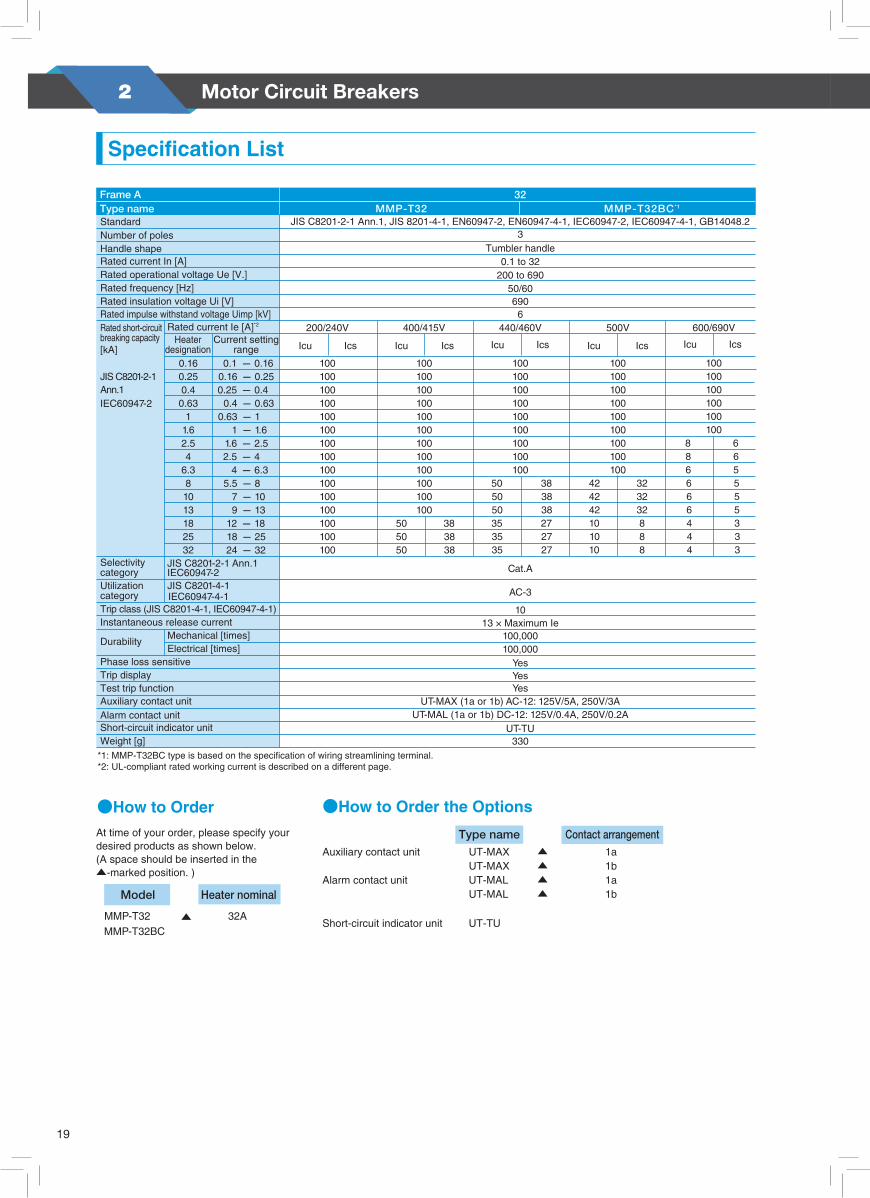
Motor Circuit Breakers2
19
MOTOR CIRCUIT BREAKERS
Specifications
14 15
Usage Environment
Operating Characteristic Curve
Optional Unit
Product name Model SpecificationNumber Description Applied model
UT-MAX
UT-MAXLL(for subtle load)
UT-MAL
UT-MALLL(for subtle load)
UT-EP3
UT-2B4
UT-3B4
UT-2B5
UT-3B5
UT-CV3
UT-TU
UT-MT20
UT-MT32
UT-BT20
UT-BT32
UT-RT10
UT-RT20
UT-RT32
1a1b1a1b1a1b1a1b
45mmTwin type45mm
Triple type58mmTwin type58mm
Triple type MMP-T32
Contact of the unit operates in conjunction with ON/OFF operation of MMP-T32.
Contact of the unit operates in conjunction with the trip operation of MMP-T32.
A unit to supply power to two or three MMP-T32.
A set of the blocks for mechanically connecting two mounting base units.
A plate to install the combination starter with MMP-T32 and Magnetic Contactor combined. Rail mounting and screw mounting are available.
A unit to connect the large size electric wire to MMP-T32.
Power supply-side terminal cover to respond to UL60947-4-1A, Type E/FThis kit consists of terminal adapter, terminal cover and 3 screws.This unit has a feature that the red lamp is lit only when the device is tripped due to short-circuit.This unit is required for application to UL60947-4-1A, Type E/F.
Auxiliary contact unit (to be internally installed)
Alarm contact unit (to be internally installed)
3 phase feed-in terminal
Bus bar
Line side terminal adapter kit
Short-circuit indicator unit
Connection conductor unit
Mounting base unit
Jointing block unit
①
②
③
④
⑤
⑥
⑥
⑦
⑧
⑨
List of Options
①② ④
③
⑤
⑧
⑦
⑨
●Option combination Diagram
(1) Ambient temperature : -10°C to 40°C (Applied to the outside of
the control panel) Average daily atmospheric temperature: 35°C (Max.), Average yearly atmospheric temperature: 25°C (Max.)(2) Maximum temperature of the
inside of the control panel : 55°C (Yearly average temperature of the inside of the control panel should be 40°C or less.) Please note that the operating characteristic may vary with the ambient temperature.(3) Ambient temperature : 45% to 85%RH However, dew condensation and freezing should be avoided.(4) Height above sea level : 2000m or less(5) Vibration : 10 to 55Hz, 19.6m/s2 or less(6) Impact : 49m/s2 or less(7) Atmosphere : Inclusion of dust, smoke, corrosive gas, moisture, salt content and the like in the atmosphere should be
avoided as much as possible. Please note that continuing to use the device in a closed condition for a long period may cause contact failure. Never use the device under an atmosphere that contains flammable gas.(8) Storage temperature/
Relative humidity : -30°C to 65°C 45% to 85%RH However, dew condensation and freezing should be avoided. The storage temperature is ambient temperature during transportation or storage and should be within the
usage temperature when starting to use the device.* As for handling, temperature adjustment, and closely-attached installation, please read the Instruction Manual.
A unit to connect and link the MMP-T32 and Magnetic Contactor electrically and mechanically.
Three-phase cold start
The momentary release characteristic is 1040% to 1560% of the maximum set current.
Three-phase hot start
0.01
0.1
1
10
100
1000
10000
100000
100 1000 10000
Op
erat
ing
tim
e(s)
Multiple of rated current (%)
MOTOR CIRCUIT BREAKERS
Specifications
12 13
MMP-T32BCMMP-T32
Model Heater nominal
32A▲
●How to Order
Auxiliary contact unit UT-MAX ▲ 1a
Type name Contact arrangement
●How to Order the Options
UT-MAX ▲ 1bAlarm contact unit UT-MAL ▲ 1a UT-MAL ▲ 1b
Short-circuit indicator unit UT-TU
Frame A
Number of poles
Rated current In [A]
Rated insulation voltage Ui [V]Rated impulse withstand voltage Uimp [kV]
3
MMP-T3232
0.1 to 32
6906
MMP-T32BC*1
Handle shape Tumbler handle
Trip class (JIS C8201-4-1, IEC60947-4-1)
Trip display
JIS C8201-2-1 Ann.1IEC60947-2
Mechanical [times]
Cat.A
AC-3
Type name
200 to 69050/60
JIS C8201-2-1Ann.1
Weight [g]
Test trip function
Electrical [times]
JIS C8201-4-1IEC60947-4-1
IEC60947-2
0.1 - 0.16
0.25 - 0.4 0.4 - 0.63 0.63 - 1 1 - 1.6 1.6 - 2.5 2.5 - 4 4 - 6.3 5.5 - 8 7 - 10 9 - 13 12 - 18 18 - 25 24 - 32
0.16 - 0.250.16
0.40.63
11.62.54
6.381013182532
0.25
200/240V 400/415V 440/460V 500V 600/690V
Icu Ics Icu Ics Icu Ics Icu Ics Icu Ics
100
100100100100100100100100100100100100100
100100
100100100100100100100100100100
505050
100
383838
100
100100100100100100100
100100
100100100100100100100
100
505050353535
383838272727
323232888
4242101010
42
44
666
4
886
33
555
3
665
100
100100100100
100
1013 × Maximum Ie
100,000100,000
YesYesYes
UT-TU
Auxiliary contact unitAlarm contact unitShort-circuit indicator unit
Standard JIS C8201-2-1 Ann.1, JIS 8201-4-1, EN60947-2, EN60947-4-1, IEC60947-2, IEC60947-4-1, GB14048.2
*1: MMP-T32BC type is based on the specification of wiring streamlining terminal.*2: UL-compliant rated working current is described on a different page.
330
Key points
45mm
MMP-T32
Test trip function
Applicable Standards■ International Standards
IEC60947-2, 60947-4-1 UL60947-4-1A, CSA C22.2 No.60947-4-1 TUV approval CE CCC■ Domestic Standards in Japan
JIS C8201-2-1 Ann.1, 8201-4-1 Electric Applicable Safety Law (Electric articles other than specified)
Specification List
A round solderless terminal is applicable.
At time of your order, please specify your desired products as shown below.(A space should be inserted in the ▲-marked position. )
Current setting range
Rated operational voltage Ue [V.]Rated frequency [Hz]
Rated short-circuit breaking capacity[kA]
Rated current Ie [A]*2
Heater designation
Selectivity categoryUtilization category
Instantaneous release current
Phase loss sensitive
Durability
UT-MAX (1a or 1b) AC-12: 125V/5A, 250V/3AUT-MAL (1a or 1b) DC-12: 125V/0.4A, 250V/0.2A
Wiring-supporting BC terminal (Option)
Adjustment dial settable to full load current Optional short-circuit indicator
unit can be added speeding up fault diagnosis.
Integrated finger protection provides convenient safety
Breaker type operating handle with off-lock hole.
The compact breaker design also allows Auxiliary contact unit (AX) and alarm contact unit (AL).

20
MOTOR CIRCUIT BREAKERS
Specifications
14 15
Usage Environment
Operating Characteristic Curve
Optional Unit
Product name Model SpecificationNumber Description Applied model
UT-MAX
UT-MAXLL(for subtle load)
UT-MAL
UT-MALLL(for subtle load)
UT-EP3
UT-2B4
UT-3B4
UT-2B5
UT-3B5
UT-CV3
UT-TU
UT-MT20
UT-MT32
UT-BT20
UT-BT32
UT-RT10
UT-RT20
UT-RT32
1a1b1a1b1a1b1a1b
45mmTwin type45mm
Triple type58mmTwin type58mm
Triple type MMP-T32
Contact of the unit operates in conjunction with ON/OFF operation of MMP-T32.
Contact of the unit operates in conjunction with the trip operation of MMP-T32.
A unit to supply power to two or three MMP-T32.
A set of the blocks for mechanically connecting two mounting base units.
A plate to install the combination starter with MMP-T32 and Magnetic Contactor combined. Rail mounting and screw mounting are available.
A unit to connect the large size electric wire to MMP-T32.
Power supply-side terminal cover to respond to UL60947-4-1A, Type E/FThis kit consists of terminal adapter, terminal cover and 3 screws.This unit has a feature that the red lamp is lit only when the device is tripped due to short-circuit.This unit is required for application to UL60947-4-1A, Type E/F.
Auxiliary contact unit (to be internally installed)
Alarm contact unit (to be internally installed)
3 phase feed-in terminal
Bus bar
Line side terminal adapter kit
Short-circuit indicator unit
Connection conductor unit
Mounting base unit
Jointing block unit
①
②
③
④
⑤
⑥
⑥
⑦
⑧
⑨
List of Options
①② ④
③
⑤
⑧
⑦
⑨
●Option combination Diagram
(1) Ambient temperature : -10°C to 40°C (Applied to the outside of
the control panel) Average daily atmospheric temperature: 35°C (Max.), Average yearly atmospheric temperature: 25°C (Max.)(2) Maximum temperature of the
inside of the control panel : 55°C (Yearly average temperature of the inside of the control panel should be 40°C or less.) Please note that the operating characteristic may vary with the ambient temperature.(3) Ambient temperature : 45% to 85%RH However, dew condensation and freezing should be avoided.(4) Height above sea level : 2000m or less(5) Vibration : 10 to 55Hz, 19.6m/s2 or less(6) Impact : 49m/s2 or less(7) Atmosphere : Inclusion of dust, smoke, corrosive gas, moisture, salt content and the like in the atmosphere should be
avoided as much as possible. Please note that continuing to use the device in a closed condition for a long period may cause contact failure. Never use the device under an atmosphere that contains flammable gas.(8) Storage temperature/
Relative humidity : -30°C to 65°C 45% to 85%RH However, dew condensation and freezing should be avoided. The storage temperature is ambient temperature during transportation or storage and should be within the
usage temperature when starting to use the device.* As for handling, temperature adjustment, and closely-attached installation, please read the Instruction Manual.
A unit to connect and link the MMP-T32 and Magnetic Contactor electrically and mechanically.
Three-phase cold start
The momentary release characteristic is 1040% to 1560% of the maximum set current.
Three-phase hot start
0.01
0.1
1
10
100
1000
10000
100000
100 1000 10000
Op
erat
ing
tim
e(s)
Multiple of rated current (%)
MOTOR CIRCUIT BREAKERS
Specifications
12 13
MMP-T32BCMMP-T32
Model Heater nominal
32A▲
●How to Order
Auxiliary contact unit UT-MAX ▲ 1a
Type name Contact arrangement
●How to Order the Options
UT-MAX ▲ 1bAlarm contact unit UT-MAL ▲ 1a UT-MAL ▲ 1b
Short-circuit indicator unit UT-TU
Frame A
Number of poles
Rated current In [A]
Rated insulation voltage Ui [V]Rated impulse withstand voltage Uimp [kV]
3
MMP-T3232
0.1 to 32
6906
MMP-T32BC*1
Handle shape Tumbler handle
Trip class (JIS C8201-4-1, IEC60947-4-1)
Trip display
JIS C8201-2-1 Ann.1IEC60947-2
Mechanical [times]
Cat.A
AC-3
Type name
200 to 69050/60
JIS C8201-2-1Ann.1
Weight [g]
Test trip function
Electrical [times]
JIS C8201-4-1IEC60947-4-1
IEC60947-2
0.1 - 0.16
0.25 - 0.4 0.4 - 0.63 0.63 - 1 1 - 1.6 1.6 - 2.5 2.5 - 4 4 - 6.3 5.5 - 8 7 - 10 9 - 13 12 - 18 18 - 25 24 - 32
0.16 - 0.250.16
0.40.63
11.62.54
6.381013182532
0.25
200/240V 400/415V 440/460V 500V 600/690V
Icu Ics Icu Ics Icu Ics Icu Ics Icu Ics
100
100100100100100100100100100100100100100
100100
100100100100100100100100100100
505050
100
383838
100
100100100100100100100
100100
100100100100100100100
100
505050353535
383838272727
323232888
4242101010
42
44
666
4
886
33
555
3
665
100
100100100100
100
1013 × Maximum Ie
100,000100,000
YesYesYes
UT-TU
Auxiliary contact unitAlarm contact unitShort-circuit indicator unit
Standard JIS C8201-2-1 Ann.1, JIS 8201-4-1, EN60947-2, EN60947-4-1, IEC60947-2, IEC60947-4-1, GB14048.2
*1: MMP-T32BC type is based on the specification of wiring streamlining terminal.*2: UL-compliant rated working current is described on a different page.
330
Key points
45mm
MMP-T32
Test trip function
Applicable Standards■ International Standards
IEC60947-2, 60947-4-1 UL60947-4-1A, CSA C22.2 No.60947-4-1 TUV approval CE CCC■ Domestic Standards in Japan
JIS C8201-2-1 Ann.1, 8201-4-1 Electric Applicable Safety Law (Electric articles other than specified)
Specification List
A round solderless terminal is applicable.
At time of your order, please specify your desired products as shown below.(A space should be inserted in the ▲-marked position. )
Current setting range
Rated operational voltage Ue [V.]Rated frequency [Hz]
Rated short-circuit breaking capacity[kA]
Rated current Ie [A]*2
Heater designation
Selectivity categoryUtilization category
Instantaneous release current
Phase loss sensitive
Durability
UT-MAX (1a or 1b) AC-12: 125V/5A, 250V/3AUT-MAL (1a or 1b) DC-12: 125V/0.4A, 250V/0.2A
Wiring-supporting BC terminal (Option)
Adjustment dial settable to full load current Optional short-circuit indicator
unit can be added speeding up fault diagnosis.
Integrated finger protection provides convenient safety
Breaker type operating handle with off-lock hole.
The compact breaker design also allows Auxiliary contact unit (AX) and alarm contact unit (AL).

21
3 Magnetic Contactor
Frame T10 T12 T20 T21 T25 T32 T35 T50 T65 T80 T100Applicable standard JIS C8201-4-1,IEC60947-4-1,EN60947-4-1,GB14048.4 JIS C8201-4-1,IEC60947-4-1,
EN60947-4-1,GB14048.4
Mod
el n
ame
Magnetic Contactors(Without Thermal Overload Relays, Open type)
Non-Reversing S-T10 S-T12 S-T20 S-T21 S-T25 S-T32 S-T35 S-T50 S-T65 S-T80 S-T100Reversing S-2×T10 S-2×T12 S-2×T20 S-2×T21 S-2×T25 S-2×T32 S-2×T35 S-2×T50 S-2×T65 S-2×T80 S-2×T100
Magnetic Starters(With standard 2-element, With Thermal Overload Relays)
EnclosedNon-Reversing MS-T10 MS-T12 ー MS-T21 MS-2×T25 ー MS-T35 MS-T50 MS-T65 MS-T80 MS-T100Reversing ー MS-2×T21 MS-T25 ー MS-2XT35 MS-2XT50 MS-2XT65 MS-2XT80 MS-2XT100
Open typeNon-Reversing MSO-T10 MSO-T12 MSO-T20 MSO-T21 MSO-T25 ー MSO-T35 MSO-T50 MSO-T65 MSO-T80 MSO-T100Reversing MSO-2×T10 MSO-2×T12 MSO-2×T20 MSO-2×T21 MSO-2×T25 ー MSO-2×T35 MSO-2×T50 MSO-2×T65 MSO-2×T80 MSO-2×T100
Combined Thermal Overload Relays TH-T18 TH-T25 TH-T25 ー TH-T25/T50 TH-T25/T50 TH-T65 TH-T65/T100 TH-T65/T100Magnetic Starters(With 3-element type Thermal Overload Relays)
Open typeNon-Reversing MSO-T10KP MSO-T12KP MSO-T20KP MSO-T21KP MSO-T25KP ー MSO-T35KP MSO-T50KP MSO-T65KP MSO-T80KP MSO-T100KPReversing MSO-2×T10KP MSO-2×T12KP MSO-2×T20KP MSO-2×T21KP MSO-2×T25KP ー MSO-2×T35KP MSO-2×T50KP MSO-2×T65KP MSO-2×T80KP MSO-2×T100KP
Combined Thermal Overload Relays TH-T18KP TH-T25KP TH-T25KP ー TH-T25/T50KP TH-T25/T50KP TH-T65KP TH-T65/T100KP TH-T65/T100KP
Mai
n co
ntac
t rat
ing
Rated insulation voltage [V] 690 690Rated impulse withstand voltage [kV] 6 6Rated frequency [Hz] 50/60 50/60Pollution degree 3 3
Rated operational current / powerCategory AC-3 (Note 1)(Three-phase squirrel-cage motor load standard responsibility) (Note 2) [kW/A]
220 to 240VAC 2.5/11 [2.2/11] 3.5/13 [2.7/13] 4.5/18 [3.7/18] 5.5/25 [4/20] 7.5/30(26) [5.5/26] 7.5/32 [7.5/32] 11/40 [7.5/35] 15/55 [11/50] 18.5/65 [15/65] 22/85 [19/80] 30/105 [22/100]380 to 440VAC 4/9 [2.7/7] 5.5/12 [4/9] 7.5/18 [7.5/18] 11/23 [7.5/20] 15/30(26) [11/25] 15/32 [15/32] 18.5/40 [15/32] 22/48 [22/48] 30/65 [30/65] 45/85 [37/80] 55/105 [45/93]
500VAC 4/7 [2.7/6] 5.5/9 [5.5/9] 7.5/17 [7.5/17] 11/17 [7.5/17] 15/24 [11/20] 15/24 [11/20] 18.5/32 [15/26] 25/38 [22/38] 37/60 [30/45] 45/75 [45/75] 55/85 [45/75]690VAC 4/5 5.5/7 7.5/9 7.5/9 11/12 11/12 15/17 22/26 30/38 45/52 55/65
Rated operational current / powerCategory AC-4(Three-phase squirrel-cage motor load inching responsibility) [kW/A]
220 to 240VAC 1.5/8 2.2/11 3.7/18 4.5/20 5.5/26 5.5/26 7.5/35 11/50 15/65 19/80380 to 440VAC 2.2/6 4/9 5.5/13 7.5/17 11/24 11/24 15/32 22/47 30/62 37/75
500VAC 2.7/6 5.5/9 5.5/10 7.5/12 7.5/13 11/17 15/24 22/38 30/45 37/55
Rated operational current / powerCategory AC-1 (Resistance, heater load)
100 to 240VAC 20 32 32 60 80 100 120 150380 to 440VAC 11 13 32 32 60 80 100 120 150
Conventional free air thermal current Ith [A] 20 32 32 60 80 100 120 150Minimum applicable load level 48V 200mA 48V 200mA
Aux
iliar
y co
ntac
t rat
ing
Con
tact
ar
rang
emen
t
Standard accessoryNon-Reversing 1a 1a1b 2a2b 2a2b ー 2a2b 2a2b 2a2b 2a2b 2a2bReversing (Note 4, Note 6) 1a×2+2b 1a1b×2+2b 2a2b×2 2a2b×2 2a2b×2 2a2b×2 2a2b×2 2a2b×2 2a2b×2 2a2b×2
Special accessoryNon-Reversing 1b 2a ー ー ー ー ー ー ーReversing (Note 4, Note 6) 1b×2+2b 2a×2+2b ー ー ー ー ー ー ー
Max. number of additional options(Note 5)
Front clip-on
Non-Reversing 1 1 ーReversing 2 2 ー 2 ー
Side clip-on
Non-Reversing 2 2Reversing 2 2 ー 2
Rated operational current(Category AC-15 : Alternating current coil load)
120VAC 6 6240VAC 3 3
Rated operational current (Category DC-13 : Direct current coil load)
24VDC 3 3110VDC 0.6 0.6
Conventional free air thermal current Ith [A] 10 10Minimum applicable load level 20V 3mA 20V 3mA
Per
form
ance
Mechanical durability [ten thousand times] 1000 1000 500
Electrical durability[ten thousand times]
Category AC-3 200(Note 9) 200 100Category AC-4 3(Note 9) 3 (Note 9)Category AC-1 50 50
Switching frequency [time/hour]Category AC-3 1800 1800 1200Category AC-4 300 300Category AC-1 1200 1200 600
Chara
cteris
tic
Coil consumption (Note 7)Inrush [VA] 45 75 75 55 110 110 115 115 210Sealed [VA] 7 7 7 4.5 10 10 20 20 23
Power consumption (Note 7) [W] 2.2 2.4 2.4 1.8 3.8 3.8 2.2 2.2 2.8
Out
side
di
men
sion
s
Magnetic Contactors (without Thermal Overload Relays)(Width x Height x Depth) [mm]
Non-Reversing 36×75×78 43×75×78 63×81×81 63×81×81 43×81×81 75×89×91 88×106×106 88×106×106 100×124×127Reversing 82×85×78 97×85×78 136×81×81 136×81×81 96×81×111 160×114×97 216×115×112 216×115×112 270×140×137
Open type Magnetic Starters(Width x Height x Depth) [mm]
Non-Reversing 45×115×79 63×128×82 63×128×82 ー 75×157.5×91 90×158×106 90×174.5×106 100×196×127Reversing 90×125×79 97×125×79 136×138×82 136×138×82 ー 160×179×97 216×169×112 216×185.5×112 270×213×137
Enclosed Magnetic Starters(Width x Height x Depth) [mm]
Non-Reversing 76×165×97.5 ー 104×176×110 ー 135×231×126 160×282×145 190×317×163Reversing ー ー 220×192×115 ー 300×247×130 320×282×140 410×347×154
IEC 35mm rail mounting Possible (excluding Enclosed Magnetic Starters) Possible (excluding Enclosed Magnetic Starters) ー
Specification List Table
●Magnetic Starters/Magnetic Contactors (AC operated)
Note 1: The figure in the square brackets indicates the rated current shown on the rating plate of the product at which the category AC-3 opening/closing durability is 2,000,000 times (1,000,000 times for the T20 380V). Refer to the electric durability curve for the life performance.
Note 2: The content within ( ) of rated capacity and rated operational current is applied to the Magnetic Contactor.Note 3: The T10 to T50 types can be manufactured with a coil surge absorber-mounted type (□-□SA type). The UT-SA21 type can be mounted.Note 4: +2b of T10 and T12 auxiliary contact arrangements in Reversing type represents b contact built in the UT-ML11 interlock unit.Note 5: The main unit and auxiliary contact block must be prepared separately and additionally mounted by the user.Note 6: For auxiliary contact arrangement in Reversing type, X2 is displayed as combined auxiliary contact arrangement of two Magnetic Contactors. Please specify the contact arrangement for which
two main units are combined must be designated. <Designation example> In case of 1b x 2 + 2b: 2BNote 7: Operational coil input and coil consumption are average values in case of applying 220V60Hz to AC200V coil.Note 8: Refer to pages 36 for the mountable options.Note 9: 1,000,000 times for T20 AC-3 Class 380V or higher, and 15,000 times for AC-4 Class. 15,000 times for T35 to T100 AC-4 Class 380V or higher.
S o l v e T o g e t h e rSelection and Application
18
Frame T10 T12 T20 T21 T25 T32 T35 T50 T65 T80 T100Applicable standard JIS C8201-4-1,IEC60947-4-1,EN60947-4-1,GB14048.4 JIS C8201-4-1,IEC60947-4-1,
EN60947-4-1,GB14048.4
Mod
el n
ame
Magnetic Contactors(Without Thermal Overload Relays, Open type)
Non-Reversing S-T10 S-T12 S-T20 S-T21 S-T25 S-T32 S-T35 S-T50 S-T65 S-T80 S-T100Reversing S-2×T10 S-2×T12 S-2×T20 S-2×T21 S-2×T25 S-2×T32 S-2×T35 S-2×T50 S-2×T65 S-2×T80 S-2×T100
Magnetic Starters(With standard 2-element, With Thermal Overload Relays)
EnclosedNon-Reversing MS-T10 MS-T12 ー MS-T21 MS-2×T25 ー MS-T35 MS-T50 MS-T65 MS-T80 MS-T100Reversing ー MS-2×T21 MS-T25 ー MS-2XT35 MS-2XT50 MS-2XT65 MS-2XT80 MS-2XT100
Open typeNon-Reversing MSO-T10 MSO-T12 MSO-T20 MSO-T21 MSO-T25 ー MSO-T35 MSO-T50 MSO-T65 MSO-T80 MSO-T100Reversing MSO-2×T10 MSO-2×T12 MSO-2×T20 MSO-2×T21 MSO-2×T25 ー MSO-2×T35 MSO-2×T50 MSO-2×T65 MSO-2×T80 MSO-2×T100
Combined Thermal Overload Relays TH-T18 TH-T25 TH-T25 ー TH-T25/T50 TH-T25/T50 TH-T65 TH-T65/T100 TH-T65/T100Magnetic Starters(With 3-element type Thermal Overload Relays)
Open typeNon-Reversing MSO-T10KP MSO-T12KP MSO-T20KP MSO-T21KP MSO-T25KP ー MSO-T35KP MSO-T50KP MSO-T65KP MSO-T80KP MSO-T100KPReversing MSO-2×T10KP MSO-2×T12KP MSO-2×T20KP MSO-2×T21KP MSO-2×T25KP ー MSO-2×T35KP MSO-2×T50KP MSO-2×T65KP MSO-2×T80KP MSO-2×T100KP
Combined Thermal Overload Relays TH-T18KP TH-T25KP TH-T25KP ー TH-T25/T50KP TH-T25/T50KP TH-T65KP TH-T65/T100KP TH-T65/T100KP
Mai
n co
ntac
t rat
ing
Rated insulation voltage [V] 690 690Rated impulse withstand voltage [kV] 6 6Rated frequency [Hz] 50/60 50/60Pollution degree 3 3
Rated operational current / powerCategory AC-3 (Note 1)(Three-phase squirrel-cage motor load standard responsibility) (Note 2) [kW/A]
220 to 240VAC 2.5/11 [2.2/11] 3.5/13 [2.7/13] 4.5/18 [3.7/18] 5.5/25 [4/20] 7.5/30(26) [5.5/26] 7.5/32 [7.5/32] 11/40 [7.5/35] 15/55 [11/50] 18.5/65 [15/65] 22/85 [19/80] 30/105 [22/100]380 to 440VAC 4/9 [2.7/7] 5.5/12 [4/9] 7.5/18 [7.5/18] 11/23 [7.5/20] 15/30(26) [11/25] 15/32 [15/32] 18.5/40 [15/32] 22/48 [22/48] 30/65 [30/65] 45/85 [37/80] 55/105 [45/93]
500VAC 4/7 [2.7/6] 5.5/9 [5.5/9] 7.5/17 [7.5/17] 11/17 [7.5/17] 15/24 [11/20] 15/24 [11/20] 18.5/32 [15/26] 25/38 [22/38] 37/60 [30/45] 45/75 [45/75] 55/85 [45/75]690VAC 4/5 5.5/7 7.5/9 7.5/9 11/12 11/12 15/17 22/26 30/38 45/52 55/65
Rated operational current / powerCategory AC-4(Three-phase squirrel-cage motor load inching responsibility) [kW/A]
220 to 240VAC 1.5/8 2.2/11 3.7/18 4.5/20 5.5/26 5.5/26 7.5/35 11/50 15/65 19/80380 to 440VAC 2.2/6 4/9 5.5/13 7.5/17 11/24 11/24 15/32 22/47 30/62 37/75
500VAC 2.7/6 5.5/9 5.5/10 7.5/12 7.5/13 11/17 15/24 22/38 30/45 37/55
Rated operational current / powerCategory AC-1 (Resistance, heater load)
100 to 240VAC 20 32 32 60 80 100 120 150380 to 440VAC 11 13 32 32 60 80 100 120 150
Conventional free air thermal current Ith [A] 20 32 32 60 80 100 120 150Minimum applicable load level 48V 200mA 48V 200mA
Aux
iliar
y co
ntac
t rat
ing
Con
tact
ar
rang
emen
t
Standard accessoryNon-Reversing 1a 1a1b 2a2b 2a2b ー 2a2b 2a2b 2a2b 2a2b 2a2bReversing (Note 4, Note 6) 1a×2+2b 1a1b×2+2b 2a2b×2 2a2b×2 2a2b×2 2a2b×2 2a2b×2 2a2b×2 2a2b×2 2a2b×2
Special accessoryNon-Reversing 1b 2a ー ー ー ー ー ー ーReversing (Note 4, Note 6) 1b×2+2b 2a×2+2b ー ー ー ー ー ー ー
Max. number of additional options(Note 5)
Front clip-on
Non-Reversing 1 1 ーReversing 2 2 ー 2 ー
Side clip-on
Non-Reversing 2 2Reversing 2 2 ー 2
Rated operational current(Category AC-15 : Alternating current coil load)
120VAC 6 6240VAC 3 3
Rated operational current (Category DC-13 : Direct current coil load)
24VDC 3 3110VDC 0.6 0.6
Conventional free air thermal current Ith [A] 10 10Minimum applicable load level 20V 3mA 20V 3mA
Per
form
ance
Mechanical durability [ten thousand times] 1000 1000 500
Electrical durability[ten thousand times]
Category AC-3 200(Note 9) 200 100Category AC-4 3(Note 9) 3 (Note 9)Category AC-1 50 50
Switching frequency [time/hour]Category AC-3 1800 1800 1200Category AC-4 300 300Category AC-1 1200 1200 600
Chara
cteris
tic
Coil consumption (Note 7)Inrush [VA] 45 75 75 55 110 110 115 115 210Sealed [VA] 7 7 7 4.5 10 10 20 20 23
Power consumption (Note 7) [W] 2.2 2.4 2.4 1.8 3.8 3.8 2.2 2.2 2.8
Out
side
di
men
sion
s
Magnetic Contactors (without Thermal Overload Relays)(Width x Height x Depth) [mm]
Non-Reversing 36×75×78 43×75×78 63×81×81 63×81×81 43×81×81 75×89×91 88×106×106 88×106×106 100×124×127Reversing 82×85×78 97×85×78 136×81×81 136×81×81 96×81×111 160×114×97 216×115×112 216×115×112 270×140×137
Open type Magnetic Starters(Width x Height x Depth) [mm]
Non-Reversing 45×115×79 63×128×82 63×128×82 ー 75×157.5×91 90×158×106 90×174.5×106 100×196×127Reversing 90×125×79 97×125×79 136×138×82 136×138×82 ー 160×179×97 216×169×112 216×185.5×112 270×213×137
Enclosed Magnetic Starters(Width x Height x Depth) [mm]
Non-Reversing 76×165×97.5 ー 104×176×110 ー 135×231×126 160×282×145 190×317×163Reversing ー ー 220×192×115 ー 300×247×130 320×282×140 410×347×154
IEC 35mm rail mounting Possible (excluding Enclosed Magnetic Starters) Possible (excluding Enclosed Magnetic Starters) ー
Specification List Table
S o l v e T o g e t h e r
MS-
T Se
ries
Intro
duct
ion
Sele
ctio
n an
d Ap
plic
atio
nAp
plicati
on to
Therm
al Over
load R
elays
Pro
duct
Intr
oduc
tion
Ove
rsea
s S
tand
ard
Type
Cod
esO
rder
Pro
cedu
reO
utlin
e D
raw
ing
War
rant
y an
d S
afet
y
19

22
Frame T10 T12 T20 T21 T25 T32 T35 T50 T65 T80 T100Applicable standard JIS C8201-4-1,IEC60947-4-1,EN60947-4-1,GB14048.4 JIS C8201-4-1,IEC60947-4-1,
EN60947-4-1,GB14048.4
Mod
el n
ame
Magnetic Contactors(Without Thermal Overload Relays, Open type)
Non-Reversing S-T10 S-T12 S-T20 S-T21 S-T25 S-T32 S-T35 S-T50 S-T65 S-T80 S-T100Reversing S-2×T10 S-2×T12 S-2×T20 S-2×T21 S-2×T25 S-2×T32 S-2×T35 S-2×T50 S-2×T65 S-2×T80 S-2×T100
Magnetic Starters(With standard 2-element, With Thermal Overload Relays)
EnclosedNon-Reversing MS-T10 MS-T12 ー MS-T21 MS-2×T25 ー MS-T35 MS-T50 MS-T65 MS-T80 MS-T100Reversing ー MS-2×T21 MS-T25 ー MS-2XT35 MS-2XT50 MS-2XT65 MS-2XT80 MS-2XT100
Open typeNon-Reversing MSO-T10 MSO-T12 MSO-T20 MSO-T21 MSO-T25 ー MSO-T35 MSO-T50 MSO-T65 MSO-T80 MSO-T100Reversing MSO-2×T10 MSO-2×T12 MSO-2×T20 MSO-2×T21 MSO-2×T25 ー MSO-2×T35 MSO-2×T50 MSO-2×T65 MSO-2×T80 MSO-2×T100
Combined Thermal Overload Relays TH-T18 TH-T25 TH-T25 ー TH-T25/T50 TH-T25/T50 TH-T65 TH-T65/T100 TH-T65/T100Magnetic Starters(With 3-element type Thermal Overload Relays)
Open typeNon-Reversing MSO-T10KP MSO-T12KP MSO-T20KP MSO-T21KP MSO-T25KP ー MSO-T35KP MSO-T50KP MSO-T65KP MSO-T80KP MSO-T100KPReversing MSO-2×T10KP MSO-2×T12KP MSO-2×T20KP MSO-2×T21KP MSO-2×T25KP ー MSO-2×T35KP MSO-2×T50KP MSO-2×T65KP MSO-2×T80KP MSO-2×T100KP
Combined Thermal Overload Relays TH-T18KP TH-T25KP TH-T25KP ー TH-T25/T50KP TH-T25/T50KP TH-T65KP TH-T65/T100KP TH-T65/T100KP
Mai
n co
ntac
t rat
ing
Rated insulation voltage [V] 690 690Rated impulse withstand voltage [kV] 6 6Rated frequency [Hz] 50/60 50/60Pollution degree 3 3
Rated operational current / powerCategory AC-3 (Note 1)(Three-phase squirrel-cage motor load standard responsibility) (Note 2) [kW/A]
220 to 240VAC 2.5/11 [2.2/11] 3.5/13 [2.7/13] 4.5/18 [3.7/18] 5.5/25 [4/20] 7.5/30(26) [5.5/26] 7.5/32 [7.5/32] 11/40 [7.5/35] 15/55 [11/50] 18.5/65 [15/65] 22/85 [19/80] 30/105 [22/100]380 to 440VAC 4/9 [2.7/7] 5.5/12 [4/9] 7.5/18 [7.5/18] 11/23 [7.5/20] 15/30(26) [11/25] 15/32 [15/32] 18.5/40 [15/32] 22/48 [22/48] 30/65 [30/65] 45/85 [37/80] 55/105 [45/93]
500VAC 4/7 [2.7/6] 5.5/9 [5.5/9] 7.5/17 [7.5/17] 11/17 [7.5/17] 15/24 [11/20] 15/24 [11/20] 18.5/32 [15/26] 25/38 [22/38] 37/60 [30/45] 45/75 [45/75] 55/85 [45/75]690VAC 4/5 5.5/7 7.5/9 7.5/9 11/12 11/12 15/17 22/26 30/38 45/52 55/65
Rated operational current / powerCategory AC-4(Three-phase squirrel-cage motor load inching responsibility) [kW/A]
220 to 240VAC 1.5/8 2.2/11 3.7/18 4.5/20 5.5/26 5.5/26 7.5/35 11/50 15/65 19/80380 to 440VAC 2.2/6 4/9 5.5/13 7.5/17 11/24 11/24 15/32 22/47 30/62 37/75
500VAC 2.7/6 5.5/9 5.5/10 7.5/12 7.5/13 11/17 15/24 22/38 30/45 37/55
Rated operational current / powerCategory AC-1 (Resistance, heater load)
100 to 240VAC 20 32 32 60 80 100 120 150380 to 440VAC 11 13 32 32 60 80 100 120 150
Conventional free air thermal current Ith [A] 20 32 32 60 80 100 120 150Minimum applicable load level 48V 200mA 48V 200mA
Aux
iliar
y co
ntac
t rat
ing
Con
tact
ar
rang
emen
t
Standard accessoryNon-Reversing 1a 1a1b 2a2b 2a2b ー 2a2b 2a2b 2a2b 2a2b 2a2bReversing (Note 4, Note 6) 1a×2+2b 1a1b×2+2b 2a2b×2 2a2b×2 2a2b×2 2a2b×2 2a2b×2 2a2b×2 2a2b×2 2a2b×2
Special accessoryNon-Reversing 1b 2a ー ー ー ー ー ー ーReversing (Note 4, Note 6) 1b×2+2b 2a×2+2b ー ー ー ー ー ー ー
Max. number of additional options(Note 5)
Front clip-on
Non-Reversing 1 1 ーReversing 2 2 ー 2 ー
Side clip-on
Non-Reversing 2 2Reversing 2 2 ー 2
Rated operational current(Category AC-15 : Alternating current coil load)
120VAC 6 6240VAC 3 3
Rated operational current (Category DC-13 : Direct current coil load)
24VDC 3 3110VDC 0.6 0.6
Conventional free air thermal current Ith [A] 10 10Minimum applicable load level 20V 3mA 20V 3mA
Per
form
ance
Mechanical durability [ten thousand times] 1000 1000 500
Electrical durability[ten thousand times]
Category AC-3 200(Note 9) 200 100Category AC-4 3(Note 9) 3 (Note 9)Category AC-1 50 50
Switching frequency [time/hour]Category AC-3 1800 1800 1200Category AC-4 300 300Category AC-1 1200 1200 600
Chara
cteris
tic
Coil consumption (Note 7)Inrush [VA] 45 75 75 55 110 110 115 115 210Sealed [VA] 7 7 7 4.5 10 10 20 20 23
Power consumption (Note 7) [W] 2.2 2.4 2.4 1.8 3.8 3.8 2.2 2.2 2.8
Out
side
di
men
sion
s
Magnetic Contactors (without Thermal Overload Relays)(Width x Height x Depth) [mm]
Non-Reversing 36×75×78 43×75×78 63×81×81 63×81×81 43×81×81 75×89×91 88×106×106 88×106×106 100×124×127Reversing 82×85×78 97×85×78 136×81×81 136×81×81 96×81×111 160×114×97 216×115×112 216×115×112 270×140×137
Open type Magnetic Starters(Width x Height x Depth) [mm]
Non-Reversing 45×115×79 63×128×82 63×128×82 ー 75×157.5×91 90×158×106 90×174.5×106 100×196×127Reversing 90×125×79 97×125×79 136×138×82 136×138×82 ー 160×179×97 216×169×112 216×185.5×112 270×213×137
Enclosed Magnetic Starters(Width x Height x Depth) [mm]
Non-Reversing 76×165×97.5 ー 104×176×110 ー 135×231×126 160×282×145 190×317×163Reversing ー ー 220×192×115 ー 300×247×130 320×282×140 410×347×154
IEC 35mm rail mounting Possible (excluding Enclosed Magnetic Starters) Possible (excluding Enclosed Magnetic Starters) ー
Specification List Table
●Magnetic Starters/Magnetic Contactors (AC operated)
Note 1: The figure in the square brackets indicates the rated current shown on the rating plate of the product at which the category AC-3 opening/closing durability is 2,000,000 times (1,000,000 times for the T20 380V). Refer to the electric durability curve for the life performance.
Note 2: The content within ( ) of rated capacity and rated operational current is applied to the Magnetic Contactor.Note 3: The T10 to T50 types can be manufactured with a coil surge absorber-mounted type (□-□SA type). The UT-SA21 type can be mounted.Note 4: +2b of T10 and T12 auxiliary contact arrangements in Reversing type represents b contact built in the UT-ML11 interlock unit.Note 5: The main unit and auxiliary contact block must be prepared separately and additionally mounted by the user.Note 6: For auxiliary contact arrangement in Reversing type, X2 is displayed as combined auxiliary contact arrangement of two Magnetic Contactors. Please specify the contact arrangement for which
two main units are combined must be designated. <Designation example> In case of 1b x 2 + 2b: 2BNote 7: Operational coil input and coil consumption are average values in case of applying 220V60Hz to AC200V coil.Note 8: Refer to pages 36 for the mountable options.Note 9: 1,000,000 times for T20 AC-3 Class 380V or higher, and 15,000 times for AC-4 Class. 15,000 times for T35 to T100 AC-4 Class 380V or higher.
S o l v e T o g e t h e rSelection and Application
18
Frame T10 T12 T20 T21 T25 T32 T35 T50 T65 T80 T100Applicable standard JIS C8201-4-1,IEC60947-4-1,EN60947-4-1,GB14048.4 JIS C8201-4-1,IEC60947-4-1,
EN60947-4-1,GB14048.4
Mod
el n
ame
Magnetic Contactors(Without Thermal Overload Relays, Open type)
Non-Reversing S-T10 S-T12 S-T20 S-T21 S-T25 S-T32 S-T35 S-T50 S-T65 S-T80 S-T100Reversing S-2×T10 S-2×T12 S-2×T20 S-2×T21 S-2×T25 S-2×T32 S-2×T35 S-2×T50 S-2×T65 S-2×T80 S-2×T100
Magnetic Starters(With standard 2-element, With Thermal Overload Relays)
EnclosedNon-Reversing MS-T10 MS-T12 ー MS-T21 MS-2×T25 ー MS-T35 MS-T50 MS-T65 MS-T80 MS-T100Reversing ー MS-2×T21 MS-T25 ー MS-2XT35 MS-2XT50 MS-2XT65 MS-2XT80 MS-2XT100
Open typeNon-Reversing MSO-T10 MSO-T12 MSO-T20 MSO-T21 MSO-T25 ー MSO-T35 MSO-T50 MSO-T65 MSO-T80 MSO-T100Reversing MSO-2×T10 MSO-2×T12 MSO-2×T20 MSO-2×T21 MSO-2×T25 ー MSO-2×T35 MSO-2×T50 MSO-2×T65 MSO-2×T80 MSO-2×T100
Combined Thermal Overload Relays TH-T18 TH-T25 TH-T25 ー TH-T25/T50 TH-T25/T50 TH-T65 TH-T65/T100 TH-T65/T100Magnetic Starters(With 3-element type Thermal Overload Relays)
Open typeNon-Reversing MSO-T10KP MSO-T12KP MSO-T20KP MSO-T21KP MSO-T25KP ー MSO-T35KP MSO-T50KP MSO-T65KP MSO-T80KP MSO-T100KPReversing MSO-2×T10KP MSO-2×T12KP MSO-2×T20KP MSO-2×T21KP MSO-2×T25KP ー MSO-2×T35KP MSO-2×T50KP MSO-2×T65KP MSO-2×T80KP MSO-2×T100KP
Combined Thermal Overload Relays TH-T18KP TH-T25KP TH-T25KP ー TH-T25/T50KP TH-T25/T50KP TH-T65KP TH-T65/T100KP TH-T65/T100KP
Mai
n co
ntac
t rat
ing
Rated insulation voltage [V] 690 690Rated impulse withstand voltage [kV] 6 6Rated frequency [Hz] 50/60 50/60Pollution degree 3 3
Rated operational current / powerCategory AC-3 (Note 1)(Three-phase squirrel-cage motor load standard responsibility) (Note 2) [kW/A]
220 to 240VAC 2.5/11 [2.2/11] 3.5/13 [2.7/13] 4.5/18 [3.7/18] 5.5/25 [4/20] 7.5/30(26) [5.5/26] 7.5/32 [7.5/32] 11/40 [7.5/35] 15/55 [11/50] 18.5/65 [15/65] 22/85 [19/80] 30/105 [22/100]380 to 440VAC 4/9 [2.7/7] 5.5/12 [4/9] 7.5/18 [7.5/18] 11/23 [7.5/20] 15/30(26) [11/25] 15/32 [15/32] 18.5/40 [15/32] 22/48 [22/48] 30/65 [30/65] 45/85 [37/80] 55/105 [45/93]
500VAC 4/7 [2.7/6] 5.5/9 [5.5/9] 7.5/17 [7.5/17] 11/17 [7.5/17] 15/24 [11/20] 15/24 [11/20] 18.5/32 [15/26] 25/38 [22/38] 37/60 [30/45] 45/75 [45/75] 55/85 [45/75]690VAC 4/5 5.5/7 7.5/9 7.5/9 11/12 11/12 15/17 22/26 30/38 45/52 55/65
Rated operational current / powerCategory AC-4(Three-phase squirrel-cage motor load inching responsibility) [kW/A]
220 to 240VAC 1.5/8 2.2/11 3.7/18 4.5/20 5.5/26 5.5/26 7.5/35 11/50 15/65 19/80380 to 440VAC 2.2/6 4/9 5.5/13 7.5/17 11/24 11/24 15/32 22/47 30/62 37/75
500VAC 2.7/6 5.5/9 5.5/10 7.5/12 7.5/13 11/17 15/24 22/38 30/45 37/55
Rated operational current / powerCategory AC-1 (Resistance, heater load)
100 to 240VAC 20 32 32 60 80 100 120 150380 to 440VAC 11 13 32 32 60 80 100 120 150
Conventional free air thermal current Ith [A] 20 32 32 60 80 100 120 150Minimum applicable load level 48V 200mA 48V 200mA
Aux
iliar
y co
ntac
t rat
ing
Con
tact
ar
rang
emen
t
Standard accessoryNon-Reversing 1a 1a1b 2a2b 2a2b ー 2a2b 2a2b 2a2b 2a2b 2a2bReversing (Note 4, Note 6) 1a×2+2b 1a1b×2+2b 2a2b×2 2a2b×2 2a2b×2 2a2b×2 2a2b×2 2a2b×2 2a2b×2 2a2b×2
Special accessoryNon-Reversing 1b 2a ー ー ー ー ー ー ーReversing (Note 4, Note 6) 1b×2+2b 2a×2+2b ー ー ー ー ー ー ー
Max. number of additional options(Note 5)
Front clip-on
Non-Reversing 1 1 ーReversing 2 2 ー 2 ー
Side clip-on
Non-Reversing 2 2Reversing 2 2 ー 2
Rated operational current(Category AC-15 : Alternating current coil load)
120VAC 6 6240VAC 3 3
Rated operational current (Category DC-13 : Direct current coil load)
24VDC 3 3110VDC 0.6 0.6
Conventional free air thermal current Ith [A] 10 10Minimum applicable load level 20V 3mA 20V 3mA
Per
form
ance
Mechanical durability [ten thousand times] 1000 1000 500
Electrical durability[ten thousand times]
Category AC-3 200(Note 9) 200 100Category AC-4 3(Note 9) 3 (Note 9)Category AC-1 50 50
Switching frequency [time/hour]Category AC-3 1800 1800 1200Category AC-4 300 300Category AC-1 1200 1200 600
Chara
cteris
tic
Coil consumption (Note 7)Inrush [VA] 45 75 75 55 110 110 115 115 210Sealed [VA] 7 7 7 4.5 10 10 20 20 23
Power consumption (Note 7) [W] 2.2 2.4 2.4 1.8 3.8 3.8 2.2 2.2 2.8
Out
side
di
men
sion
s
Magnetic Contactors (without Thermal Overload Relays)(Width x Height x Depth) [mm]
Non-Reversing 36×75×78 43×75×78 63×81×81 63×81×81 43×81×81 75×89×91 88×106×106 88×106×106 100×124×127Reversing 82×85×78 97×85×78 136×81×81 136×81×81 96×81×111 160×114×97 216×115×112 216×115×112 270×140×137
Open type Magnetic Starters(Width x Height x Depth) [mm]
Non-Reversing 45×115×79 63×128×82 63×128×82 ー 75×157.5×91 90×158×106 90×174.5×106 100×196×127Reversing 90×125×79 97×125×79 136×138×82 136×138×82 ー 160×179×97 216×169×112 216×185.5×112 270×213×137
Enclosed Magnetic Starters(Width x Height x Depth) [mm]
Non-Reversing 76×165×97.5 ー 104×176×110 ー 135×231×126 160×282×145 190×317×163Reversing ー ー 220×192×115 ー 300×247×130 320×282×140 410×347×154
IEC 35mm rail mounting Possible (excluding Enclosed Magnetic Starters) Possible (excluding Enclosed Magnetic Starters) ー
Specification List Table
S o l v e T o g e t h e r
MS-
T Se
ries
Intro
duct
ion
Sele
ctio
n an
d Ap
plic
atio
nAp
plicati
on to
Therm
al Over
load R
elays
Pro
duct
Intr
oduc
tion
Ove
rsea
s S
tand
ard
Type
Cod
esO
rder
Pro
cedu
reO
utlin
e D
raw
ing
War
rant
y an
d S
afet
y
19
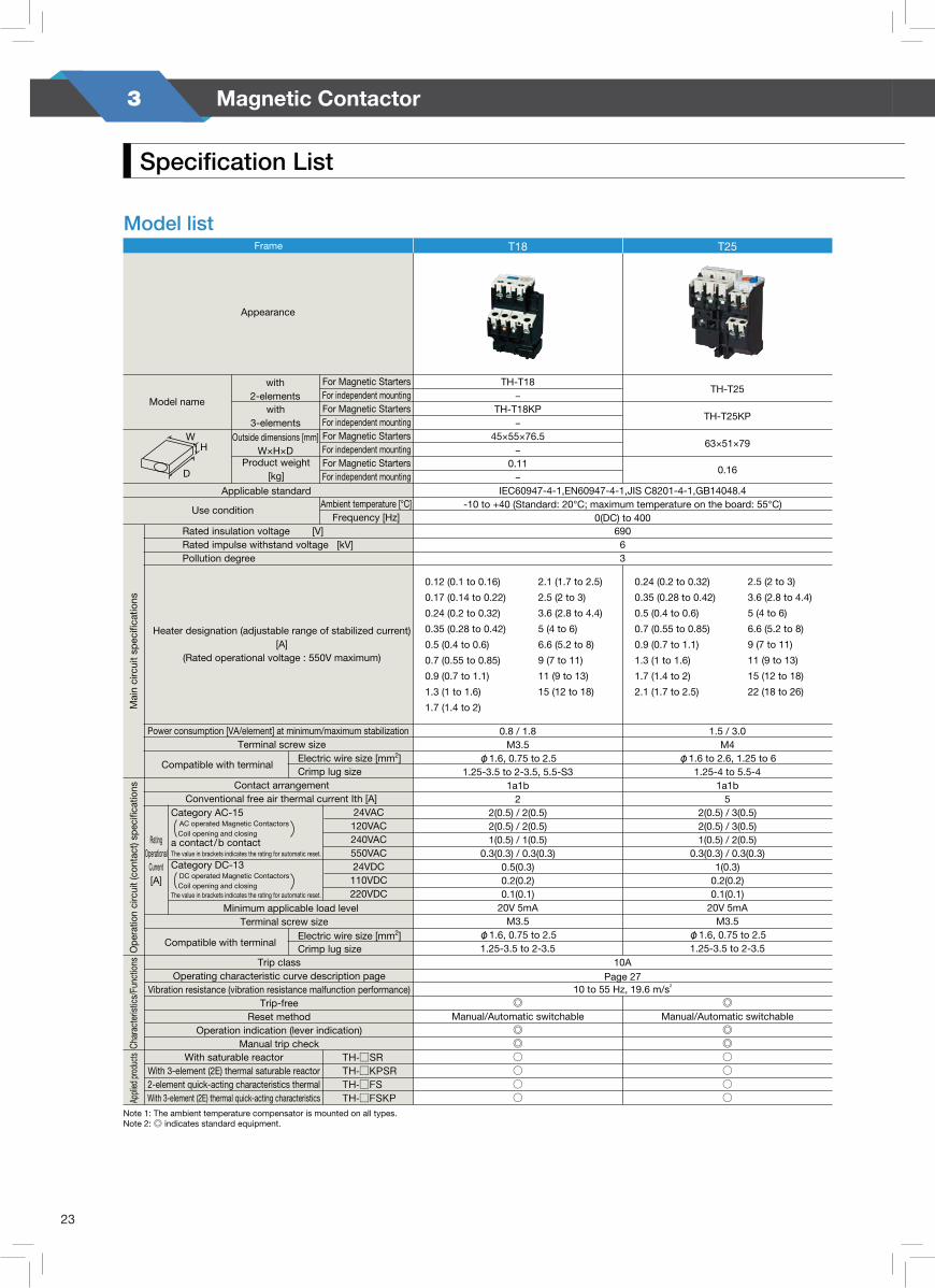
23
3 Magnetic Contactor
Appearance
T50Frame T100T65
Model name
Applicable standard
Use conditionAmbient temperature [°C]
Frequency [Hz]
For Magnetic StartersFor independent mountingFor Magnetic StartersFor independent mountingFor Magnetic StartersFor independent mountingFor Magnetic StartersFor independent mounting
with2-elements
D
HW
with 3-elements
Heater designation (adjustable range of stabilized current)[A]
(Rated operational voltage : 550V maximum)
Rated insulation voltage [V]Rated impulse withstand voltage [kV]Pollution degree
Power consumption [VA/element] at minimum/maximum stabilizationTerminal screw size
Terminal screw size
Contact arrangementConventional free air thermal current Ith [A]
24VAC120VAC240VAC550VAC24VDC110VDC220VDC
TH-□SRTH-□KPSRTH-□FSTH-□FSKP
Compatible with terminalElectric wire size [mm2]
Crimp lug size
Compatible with terminalElectric wire size [mm2]
Crimp lug size
RatingOperational
Current[A]
Minimum applicable load level
Trip classOperating characteristic curve description page
Vibration resistance (vibration resistance malfunction performance)Trip-free
Reset methodOperation indication (lever indication)
Manual trip check
Appli
ed pr
oduc
tsM
ain
circ
uit s
peci
ficat
ions
Note 1: The ambient temperature compensator is mounted on all types.Note 2: ◎ indicates standard equipment.
IEC60947-4-1,EN60947-4-1,JIS C8201-4-1,GB14048.4-10 to +40 (Standard: 20°C; maximum temperature on the board: 55°C)
0(DC) to 40069063
10 to 55Hz 19.6m/s2
29 (24 to 34)35 (30 to 40)42 (34 to 50)
15 (12 to 18)22 (18 to 26)29 (24 to 34)35 (30 to 40)42 (34 to 50)54 (43 to 65)
TH-T50-
TH-T50KP-
74.3×72×83.5-0.2-
TH-T65
TH-T65KP
89×57×83.5
0.26
TH-T100-
TH-T100KP-
89×73.5×83.5-
0.32-
1.6/3.2M5
φ5.5 to 145.5-5 to 14-5
1a1b5
2(0.5) / 3(0.5)2(0.5) / 3(0.5)1(0.5) / 2(0.5)
0.3(0.3) / 0.3(0.3)1(0.3)
0.2(0.2)0.1(0.1)20V 5mA
M3.5φ1.6, 1.25 to 21.25-3.5 to 2-3.5
10A
◎Manual/Automatic switchable
◎◎
○(TH-T50SR)○(TH-T50KPSR)
△(TH-T50FS)△(TH-T50FSKP)
2.4/5.5M6-
5.5-6 to 22-61a1b
52(0.5) / 3(0.5)2(0.5) / 3(0.5)1(0.5) / 2(0.5)0.5(0.5) / 1(0.5)
1(0.3)0.2(0.2)0.1(0.1)20V 5mA
M4φ1.6, 1.25 to 2
1.25-4 to 2-4, 5.5-S415 to 42A:10 54A:10A
◎Manual/Automatic switchable
◎◎
○(TH-T65SR)○(TH-T65KPSR)
△(TH-T65FS)△(TH-T65FSKP)
67 (54 to 80)82 (65 to 100)
2.5/6.0M6-
14-6 to 22-6、38-S61a1b
52(0.5) / 3(0.5)2(0.5) / 3(0.5)1(0.5) / 2(0.5)0.5(0.5) / 1(0.5)
1(0.3)0.2(0.2)0.1(0.1)20V 5mA
M4φ1.6, 1.25 to 2
1.25-4 to 2-4, 5.5-S467A:10 82A:10A
◎Manual/Automatic switchable
◎◎
○(TH-T100SR)○(TH-T100KPSR)△(TH-T100FS)
△(TH-T100FSKP)
Outside dimensions [mm]W×H×D
Product weight[kg]
Category AC-15 AC operated Magnetic Contactors
Coil opening and closinga contact/b contactThe value in brackets indicates the rating for automatic reset.
Category DC-13 DC operated Magnetic Contactors
Coil opening and closingThe value in brackets indicates the rating for automatic reset.
Ope
ratio
n ci
rcui
t (co
ntac
t) sp
ecifi
catio
ns
Thermal Overload Relays
Char
acte
ristic
s/Fu
nctio
ns
Model list
Page 27
With saturable reactorWith 3-element (2E) thermal saturable reactor2-element quick-acting characteristics thermalWith 3-element (2E) thermal quick-acting characteristics
0.8 / 1.8M3.5
φ1.6, 0.75 to 2.51.25-3.5 to 2-3.5, 5.5-S3
1a1b2
2(0.5) / 2(0.5)2(0.5) / 2(0.5)1(0.5) / 1(0.5)
0.3(0.3) / 0.3(0.3)0.5(0.3)0.2(0.2)0.1(0.1)
20V 5mAM3.5
φ1.6, 0.75 to 2.51.25-3.5 to 2-3.5
◎
◎◎
Model list
Appearance
T18Frame T25
Model name
Applicable standard
Use conditionAmbient temperature [°C]
Frequency [Hz]
For Magnetic StartersFor independent mountingFor Magnetic StartersFor independent mountingFor Magnetic StartersFor independent mountingFor Magnetic StartersFor independent mounting
Outside dimensions [mm]W×H×D
Product weight[kg]D
HW
Heater designation (adjustable range of stabilized current)[A]
(Rated operational voltage : 550V maximum)
Rated insulation voltage [V]Rated impulse withstand voltage [kV]Pollution degree
IEC60947-4-1,EN60947-4-1,JIS C8201-4-1,GB14048.4-10 to +40 (Standard: 20°C; maximum temperature on the board: 55°C)
0(DC) to 40069063
0.12 (0.1 to 0.16)
0.17 (0.14 to 0.22)
0.24 (0.2 to 0.32)
0.35 (0.28 to 0.42)
0.5 (0.4 to 0.6)
0.7 (0.55 to 0.85)
0.9 (0.7 to 1.1)
1.3 (1 to 1.6)
1.7 (1.4 to 2)
0.24 (0.2 to 0.32)
0.35 (0.28 to 0.42)
0.5 (0.4 to 0.6)
0.7 (0.55 to 0.85)
0.9 (0.7 to 1.1)
1.3 (1 to 1.6)
1.7 (1.4 to 2)
2.1 (1.7 to 2.5)
2.1 (1.7 to 2.5)
2.5 (2 to 3)
3.6 (2.8 to 4.4)
5 (4 to 6)
6.6 (5.2 to 8)
9 (7 to 11)
11 (9 to 13)
15 (12 to 18)
2.5 (2 to 3)
3.6 (2.8 to 4.4)
5 (4 to 6)
6.6 (5.2 to 8)
9 (7 to 11)
11 (9 to 13)
15 (12 to 18)
22 (18 to 26)
TH-T18–
TH-T18KP–
45×55×76.5–
0.11–
TH-T25
TH-T25KP
63×51×79
0.16
Power consumption [VA/element] at minimum/maximum stabilizationTerminal screw size
Terminal screw size
Contact arrangementConventional free air thermal current Ith [A]
24VAC120VAC240VAC550VAC24VDC110VDC220VDC
TH-□SRTH-□KPSRTH-□FSTH-□FSKP
Compatible with terminalElectric wire size [mm2]Crimp lug size
Compatible with terminalElectric wire size [mm2]
10 to 55 Hz, 19.6 m/s2
10APage 27
Crimp lug size
RatingOperational
Current[A]
Minimum applicable load level
Trip classOperating characteristic curve description page
Vibration resistance (vibration resistance malfunction performance)Trip-free
Reset methodOperation indication (lever indication)
Manual trip checkWith saturable reactor
With 3-element (2E) thermal saturable reactor2-element quick-acting characteristics thermalWith 3-element (2E) thermal quick-acting characteristicsAp
plied
prod
ucts
0.8 / 1.8M3.5
φ1.6, 0.75 to 2.51.25-3.5 to 2-3.5, 5.5-S3
1a1b2
2(0.5) / 2(0.5)2(0.5) / 2(0.5)1(0.5) / 1(0.5)
0.3(0.3) / 0.3(0.3)0.5(0.3)0.2(0.2)0.1(0.1)
20V 5mAM3.5
φ1.6, 0.75 to 2.51.25-3.5 to 2-3.5
◎Manual/Automatic switchable
◎◎○○○○
1.5 / 3.0M4
φ1.6 to 2.6, 1.25 to 61.25-4 to 5.5-4
1a1b5
2(0.5) / 3(0.5)2(0.5) / 3(0.5)1(0.5) / 2(0.5)
0.3(0.3) / 0.3(0.3)1(0.3)
0.2(0.2)0.1(0.1)
20V 5mAM3.5
φ1.6, 0.75 to 2.51.25-3.5 to 2-3.5
◎Manual/Automatic switchable
◎◎○○○○
Note 1: The ambient temperature compensator is mounted on all types.Note 2: ◎ indicates standard equipment.
Specification List
with 2-elements
with 3-elements
Category AC-15 AC operated Magnetic Contactors
Coil opening and closinga contact/b contact
Category DC-13 DC operated Magnetic Contactors
Coil opening and closing
Char
acte
ristic
s/Fu
nctio
nsO
pera
tion
circ
uit (
cont
act)
spec
ifica
tions
Mai
n ci
rcui
t spe
cific
atio
ns
The value in brackets indicates the rating for automatic reset.
The value in brackets indicates the rating for automatic reset.
S o l v e T o g e t h e rApplication to Thermal Overload Relays
24
Appearance
T50Frame T100T65
Model name
Applicable standard
Use conditionAmbient temperature [°C]
Frequency [Hz]
For Magnetic StartersFor independent mountingFor Magnetic StartersFor independent mountingFor Magnetic StartersFor independent mountingFor Magnetic StartersFor independent mounting
with2-elements
D
HW
with 3-elements
Heater designation (adjustable range of stabilized current)[A]
(Rated operational voltage : 550V maximum)
Rated insulation voltage [V]Rated impulse withstand voltage [kV]Pollution degree
Power consumption [VA/element] at minimum/maximum stabilizationTerminal screw size
Terminal screw size
Contact arrangementConventional free air thermal current Ith [A]
24VAC120VAC240VAC550VAC24VDC110VDC220VDC
TH-□SRTH-□KPSRTH-□FSTH-□FSKP
Compatible with terminalElectric wire size [mm2]
Crimp lug size
Compatible with terminalElectric wire size [mm2]
Crimp lug size
RatingOperational
Current[A]
Minimum applicable load level
Trip classOperating characteristic curve description page
Vibration resistance (vibration resistance malfunction performance)Trip-free
Reset methodOperation indication (lever indication)
Manual trip check
Appli
ed pr
oduc
tsM
ain
circ
uit s
peci
ficat
ions
Note 1: The ambient temperature compensator is mounted on all types.Note 2: ◎ indicates standard equipment.
IEC60947-4-1,EN60947-4-1,JIS C8201-4-1,GB14048.4-10 to +40 (Standard: 20°C; maximum temperature on the board: 55°C)
0(DC) to 40069063
10 to 55Hz 19.6m/s2
29 (24 to 34)35 (30 to 40)42 (34 to 50)
15 (12 to 18)22 (18 to 26)29 (24 to 34)35 (30 to 40)42 (34 to 50)54 (43 to 65)
TH-T50-
TH-T50KP-
74.3×72×83.5-0.2-
TH-T65
TH-T65KP
89×57×83.5
0.26
TH-T100-
TH-T100KP-
89×73.5×83.5-
0.32-
1.6/3.2M5
φ5.5 to 145.5-5 to 14-5
1a1b5
2(0.5) / 3(0.5)2(0.5) / 3(0.5)1(0.5) / 2(0.5)
0.3(0.3) / 0.3(0.3)1(0.3)
0.2(0.2)0.1(0.1)20V 5mA
M3.5φ1.6, 1.25 to 21.25-3.5 to 2-3.5
10A
◎Manual/Automatic switchable
◎◎
○(TH-T50SR)○(TH-T50KPSR)
△(TH-T50FS)△(TH-T50FSKP)
2.4/5.5M6-
5.5-6 to 22-61a1b
52(0.5) / 3(0.5)2(0.5) / 3(0.5)1(0.5) / 2(0.5)0.5(0.5) / 1(0.5)
1(0.3)0.2(0.2)0.1(0.1)20V 5mA
M4φ1.6, 1.25 to 2
1.25-4 to 2-4, 5.5-S415 to 42A:10 54A:10A
◎Manual/Automatic switchable
◎◎
○(TH-T65SR)○(TH-T65KPSR)
△(TH-T65FS)△(TH-T65FSKP)
67 (54 to 80)82 (65 to 100)
2.5/6.0M6-
14-6 to 22-6、38-S61a1b
52(0.5) / 3(0.5)2(0.5) / 3(0.5)1(0.5) / 2(0.5)0.5(0.5) / 1(0.5)
1(0.3)0.2(0.2)0.1(0.1)20V 5mA
M4φ1.6, 1.25 to 2
1.25-4 to 2-4, 5.5-S467A:10 82A:10A
◎Manual/Automatic switchable
◎◎
○(TH-T100SR)○(TH-T100KPSR)△(TH-T100FS)
△(TH-T100FSKP)
Outside dimensions [mm]W×H×D
Product weight[kg]
Category AC-15 AC operated Magnetic Contactors
Coil opening and closinga contact/b contactThe value in brackets indicates the rating for automatic reset.
Category DC-13 DC operated Magnetic Contactors
Coil opening and closingThe value in brackets indicates the rating for automatic reset.
Ope
ratio
n ci
rcui
t (co
ntac
t) sp
ecifi
catio
ns
Thermal Overload Relays
Char
acte
ristic
s/Fu
nctio
ns
Model list
Page 27
With saturable reactorWith 3-element (2E) thermal saturable reactor2-element quick-acting characteristics thermalWith 3-element (2E) thermal quick-acting characteristics
0.8 / 1.8M3.5
φ1.6, 0.75 to 2.51.25-3.5 to 2-3.5, 5.5-S3
1a1b2
2(0.5) / 2(0.5)2(0.5) / 2(0.5)1(0.5) / 1(0.5)
0.3(0.3) / 0.3(0.3)0.5(0.3)0.2(0.2)0.1(0.1)
20V 5mAM3.5
φ1.6, 0.75 to 2.51.25-3.5 to 2-3.5
◎
◎◎
S o l v e T o g e t h e r
MS-
T Se
ries
Intro
duct
ion
Sele
ctio
n an
d Ap
plic
atio
nAp
plicati
on to
Therm
al Over
load R
elays
Pro
duct
Intr
oduc
tion
Ove
rsea
s S
tand
ard
Type
Cod
esO
rder
Pro
cedu
reO
utlin
e D
raw
ing
War
rant
y an
d S
afet
y
25

24
Appearance
T50Frame T100T65
Model name
Applicable standard
Use conditionAmbient temperature [°C]
Frequency [Hz]
For Magnetic StartersFor independent mountingFor Magnetic StartersFor independent mountingFor Magnetic StartersFor independent mountingFor Magnetic StartersFor independent mounting
with2-elements
D
HW
with 3-elements
Heater designation (adjustable range of stabilized current)[A]
(Rated operational voltage : 550V maximum)
Rated insulation voltage [V]Rated impulse withstand voltage [kV]Pollution degree
Power consumption [VA/element] at minimum/maximum stabilizationTerminal screw size
Terminal screw size
Contact arrangementConventional free air thermal current Ith [A]
24VAC120VAC240VAC550VAC24VDC110VDC220VDC
TH-□SRTH-□KPSRTH-□FSTH-□FSKP
Compatible with terminalElectric wire size [mm2]
Crimp lug size
Compatible with terminalElectric wire size [mm2]
Crimp lug size
RatingOperational
Current[A]
Minimum applicable load level
Trip classOperating characteristic curve description page
Vibration resistance (vibration resistance malfunction performance)Trip-free
Reset methodOperation indication (lever indication)
Manual trip check
Appli
ed pr
oduc
tsM
ain
circ
uit s
peci
ficat
ions
Note 1: The ambient temperature compensator is mounted on all types.Note 2: ◎ indicates standard equipment.
IEC60947-4-1,EN60947-4-1,JIS C8201-4-1,GB14048.4-10 to +40 (Standard: 20°C; maximum temperature on the board: 55°C)
0(DC) to 40069063
10 to 55Hz 19.6m/s2
29 (24 to 34)35 (30 to 40)42 (34 to 50)
15 (12 to 18)22 (18 to 26)29 (24 to 34)35 (30 to 40)42 (34 to 50)54 (43 to 65)
TH-T50-
TH-T50KP-
74.3×72×83.5-0.2-
TH-T65
TH-T65KP
89×57×83.5
0.26
TH-T100-
TH-T100KP-
89×73.5×83.5-
0.32-
1.6/3.2M5
φ5.5 to 145.5-5 to 14-5
1a1b5
2(0.5) / 3(0.5)2(0.5) / 3(0.5)1(0.5) / 2(0.5)
0.3(0.3) / 0.3(0.3)1(0.3)
0.2(0.2)0.1(0.1)20V 5mA
M3.5φ1.6, 1.25 to 21.25-3.5 to 2-3.5
10A
◎Manual/Automatic switchable
◎◎
○(TH-T50SR)○(TH-T50KPSR)
△(TH-T50FS)△(TH-T50FSKP)
2.4/5.5M6-
5.5-6 to 22-61a1b
52(0.5) / 3(0.5)2(0.5) / 3(0.5)1(0.5) / 2(0.5)0.5(0.5) / 1(0.5)
1(0.3)0.2(0.2)0.1(0.1)20V 5mA
M4φ1.6, 1.25 to 2
1.25-4 to 2-4, 5.5-S415 to 42A:10 54A:10A
◎Manual/Automatic switchable
◎◎
○(TH-T65SR)○(TH-T65KPSR)
△(TH-T65FS)△(TH-T65FSKP)
67 (54 to 80)82 (65 to 100)
2.5/6.0M6-
14-6 to 22-6、38-S61a1b
52(0.5) / 3(0.5)2(0.5) / 3(0.5)1(0.5) / 2(0.5)0.5(0.5) / 1(0.5)
1(0.3)0.2(0.2)0.1(0.1)20V 5mA
M4φ1.6, 1.25 to 2
1.25-4 to 2-4, 5.5-S467A:10 82A:10A
◎Manual/Automatic switchable
◎◎
○(TH-T100SR)○(TH-T100KPSR)△(TH-T100FS)
△(TH-T100FSKP)
Outside dimensions [mm]W×H×D
Product weight[kg]
Category AC-15 AC operated Magnetic Contactors
Coil opening and closinga contact/b contactThe value in brackets indicates the rating for automatic reset.
Category DC-13 DC operated Magnetic Contactors
Coil opening and closingThe value in brackets indicates the rating for automatic reset.
Ope
ratio
n ci
rcui
t (co
ntac
t) sp
ecifi
catio
ns
Thermal Overload Relays
Char
acte
ristic
s/Fu
nctio
ns
Model list
Page 27
With saturable reactorWith 3-element (2E) thermal saturable reactor2-element quick-acting characteristics thermalWith 3-element (2E) thermal quick-acting characteristics
0.8 / 1.8M3.5
φ1.6, 0.75 to 2.51.25-3.5 to 2-3.5, 5.5-S3
1a1b2
2(0.5) / 2(0.5)2(0.5) / 2(0.5)1(0.5) / 1(0.5)
0.3(0.3) / 0.3(0.3)0.5(0.3)0.2(0.2)0.1(0.1)
20V 5mAM3.5
φ1.6, 0.75 to 2.51.25-3.5 to 2-3.5
◎
◎◎
Model list
Appearance
T18Frame T25
Model name
Applicable standard
Use conditionAmbient temperature [°C]
Frequency [Hz]
For Magnetic StartersFor independent mountingFor Magnetic StartersFor independent mountingFor Magnetic StartersFor independent mountingFor Magnetic StartersFor independent mounting
Outside dimensions [mm]W×H×D
Product weight[kg]D
HW
Heater designation (adjustable range of stabilized current)[A]
(Rated operational voltage : 550V maximum)
Rated insulation voltage [V]Rated impulse withstand voltage [kV]Pollution degree
IEC60947-4-1,EN60947-4-1,JIS C8201-4-1,GB14048.4-10 to +40 (Standard: 20°C; maximum temperature on the board: 55°C)
0(DC) to 40069063
0.12 (0.1 to 0.16)
0.17 (0.14 to 0.22)
0.24 (0.2 to 0.32)
0.35 (0.28 to 0.42)
0.5 (0.4 to 0.6)
0.7 (0.55 to 0.85)
0.9 (0.7 to 1.1)
1.3 (1 to 1.6)
1.7 (1.4 to 2)
0.24 (0.2 to 0.32)
0.35 (0.28 to 0.42)
0.5 (0.4 to 0.6)
0.7 (0.55 to 0.85)
0.9 (0.7 to 1.1)
1.3 (1 to 1.6)
1.7 (1.4 to 2)
2.1 (1.7 to 2.5)
2.1 (1.7 to 2.5)
2.5 (2 to 3)
3.6 (2.8 to 4.4)
5 (4 to 6)
6.6 (5.2 to 8)
9 (7 to 11)
11 (9 to 13)
15 (12 to 18)
2.5 (2 to 3)
3.6 (2.8 to 4.4)
5 (4 to 6)
6.6 (5.2 to 8)
9 (7 to 11)
11 (9 to 13)
15 (12 to 18)
22 (18 to 26)
TH-T18–
TH-T18KP–
45×55×76.5–
0.11–
TH-T25
TH-T25KP
63×51×79
0.16
Power consumption [VA/element] at minimum/maximum stabilizationTerminal screw size
Terminal screw size
Contact arrangementConventional free air thermal current Ith [A]
24VAC120VAC240VAC550VAC24VDC
110VDC220VDC
TH-□SRTH-□KPSRTH-□FSTH-□FSKP
Compatible with terminalElectric wire size [mm2]Crimp lug size
Compatible with terminalElectric wire size [mm2]
10 to 55 Hz, 19.6 m/s2
10APage 27
Crimp lug size
RatingOperational
Current[A]
Minimum applicable load level
Trip classOperating characteristic curve description page
Vibration resistance (vibration resistance malfunction performance)Trip-free
Reset methodOperation indication (lever indication)
Manual trip checkWith saturable reactor
With 3-element (2E) thermal saturable reactor2-element quick-acting characteristics thermalWith 3-element (2E) thermal quick-acting characteristicsAp
plied
prod
ucts
0.8 / 1.8M3.5
φ1.6, 0.75 to 2.51.25-3.5 to 2-3.5, 5.5-S3
1a1b2
2(0.5) / 2(0.5)2(0.5) / 2(0.5)1(0.5) / 1(0.5)
0.3(0.3) / 0.3(0.3)0.5(0.3)0.2(0.2)0.1(0.1)
20V 5mAM3.5
φ1.6, 0.75 to 2.51.25-3.5 to 2-3.5
◎Manual/Automatic switchable
◎◎○○○○
1.5 / 3.0M4
φ1.6 to 2.6, 1.25 to 61.25-4 to 5.5-4
1a1b5
2(0.5) / 3(0.5)2(0.5) / 3(0.5)1(0.5) / 2(0.5)
0.3(0.3) / 0.3(0.3)1(0.3)
0.2(0.2)0.1(0.1)
20V 5mAM3.5
φ1.6, 0.75 to 2.51.25-3.5 to 2-3.5
◎Manual/Automatic switchable
◎◎○○○○
Note 1: The ambient temperature compensator is mounted on all types.Note 2: ◎ indicates standard equipment.
Specification List
with 2-elements
with 3-elements
Category AC-15 AC operated Magnetic Contactors
Coil opening and closinga contact/b contact
Category DC-13 DC operated Magnetic Contactors
Coil opening and closing
Char
acte
ristic
s/Fu
nctio
nsO
pera
tion
circ
uit (
cont
act)
spec
ifica
tions
Mai
n ci
rcui
t spe
cific
atio
ns
The value in brackets indicates the rating for automatic reset.
The value in brackets indicates the rating for automatic reset.
S o l v e T o g e t h e rApplication to Thermal Overload Relays
24
Appearance
T50Frame T100T65
Model name
Applicable standard
Use conditionAmbient temperature [°C]
Frequency [Hz]
For Magnetic StartersFor independent mountingFor Magnetic StartersFor independent mountingFor Magnetic StartersFor independent mountingFor Magnetic StartersFor independent mounting
with2-elements
D
HW
with 3-elements
Heater designation (adjustable range of stabilized current)[A]
(Rated operational voltage : 550V maximum)
Rated insulation voltage [V]Rated impulse withstand voltage [kV]Pollution degree
Power consumption [VA/element] at minimum/maximum stabilizationTerminal screw size
Terminal screw size
Contact arrangementConventional free air thermal current Ith [A]
24VAC120VAC240VAC550VAC24VDC110VDC220VDC
TH-□SRTH-□KPSRTH-□FSTH-□FSKP
Compatible with terminalElectric wire size [mm2]
Crimp lug size
Compatible with terminalElectric wire size [mm2]
Crimp lug size
RatingOperational
Current[A]
Minimum applicable load level
Trip classOperating characteristic curve description page
Vibration resistance (vibration resistance malfunction performance)Trip-free
Reset methodOperation indication (lever indication)
Manual trip check
Appli
ed pr
oduc
tsM
ain
circ
uit s
peci
ficat
ions
Note 1: The ambient temperature compensator is mounted on all types.Note 2: ◎ indicates standard equipment.
IEC60947-4-1,EN60947-4-1,JIS C8201-4-1,GB14048.4-10 to +40 (Standard: 20°C; maximum temperature on the board: 55°C)
0(DC) to 40069063
10 to 55Hz 19.6m/s2
29 (24 to 34)35 (30 to 40)42 (34 to 50)
15 (12 to 18)22 (18 to 26)29 (24 to 34)35 (30 to 40)42 (34 to 50)54 (43 to 65)
TH-T50-
TH-T50KP-
74.3×72×83.5-0.2-
TH-T65
TH-T65KP
89×57×83.5
0.26
TH-T100-
TH-T100KP-
89×73.5×83.5-
0.32-
1.6/3.2M5
φ5.5 to 145.5-5 to 14-5
1a1b5
2(0.5) / 3(0.5)2(0.5) / 3(0.5)1(0.5) / 2(0.5)
0.3(0.3) / 0.3(0.3)1(0.3)
0.2(0.2)0.1(0.1)20V 5mA
M3.5φ1.6, 1.25 to 21.25-3.5 to 2-3.5
10A
◎Manual/Automatic switchable
◎◎
○(TH-T50SR)○(TH-T50KPSR)
△(TH-T50FS)△(TH-T50FSKP)
2.4/5.5M6-
5.5-6 to 22-61a1b
52(0.5) / 3(0.5)2(0.5) / 3(0.5)1(0.5) / 2(0.5)0.5(0.5) / 1(0.5)
1(0.3)0.2(0.2)0.1(0.1)20V 5mA
M4φ1.6, 1.25 to 2
1.25-4 to 2-4, 5.5-S415 to 42A:10 54A:10A
◎Manual/Automatic switchable
◎◎
○(TH-T65SR)○(TH-T65KPSR)
△(TH-T65FS)△(TH-T65FSKP)
67 (54 to 80)82 (65 to 100)
2.5/6.0M6-
14-6 to 22-6、38-S61a1b
52(0.5) / 3(0.5)2(0.5) / 3(0.5)1(0.5) / 2(0.5)0.5(0.5) / 1(0.5)
1(0.3)0.2(0.2)0.1(0.1)20V 5mA
M4φ1.6, 1.25 to 2
1.25-4 to 2-4, 5.5-S467A:10 82A:10A
◎Manual/Automatic switchable
◎◎
○(TH-T100SR)○(TH-T100KPSR)△(TH-T100FS)
△(TH-T100FSKP)
Outside dimensions [mm]W×H×D
Product weight[kg]
Category AC-15 AC operated Magnetic Contactors
Coil opening and closinga contact/b contactThe value in brackets indicates the rating for automatic reset.
Category DC-13 DC operated Magnetic Contactors
Coil opening and closingThe value in brackets indicates the rating for automatic reset.
Ope
ratio
n ci
rcui
t (co
ntac
t) sp
ecifi
catio
ns
Thermal Overload Relays
Char
acte
ristic
s/Fu
nctio
ns
Model list
Page 27
With saturable reactorWith 3-element (2E) thermal saturable reactor2-element quick-acting characteristics thermalWith 3-element (2E) thermal quick-acting characteristics
0.8 / 1.8M3.5
φ1.6, 0.75 to 2.51.25-3.5 to 2-3.5, 5.5-S3
1a1b2
2(0.5) / 2(0.5)2(0.5) / 2(0.5)1(0.5) / 1(0.5)
0.3(0.3) / 0.3(0.3)0.5(0.3)0.2(0.2)0.1(0.1)
20V 5mAM3.5
φ1.6, 0.75 to 2.51.25-3.5 to 2-3.5
◎
◎◎
S o l v e T o g e t h e r
MS-
T Se
ries
Intro
duct
ion
Sele
ctio
n an
d Ap
plic
atio
nAp
plicati
on to
Therm
al Over
load R
elays
Pro
duct
Intr
oduc
tion
Ove
rsea
s S
tand
ard
Type
Cod
esO
rder
Pro
cedu
reO
utlin
e D
raw
ing
War
rant
y an
d S
afet
y
25
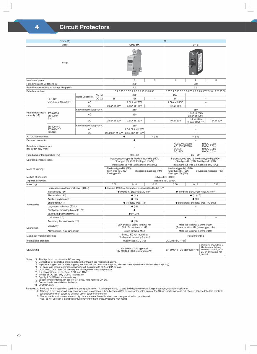
25
4 Circuit Protectors
51
2
Frame (A) 30
Model CP30-BA CP-S
Image
Number of poles 1 2 3 1 2 3
Rated insulation voltage Ui (V) 250 250
Rated impulse withstand voltage Uimp (kV) 2.5 2.5
Rated current (A) 0.1 0.25 0.3 0.5 1 2 3 5 7 10 15 20 30 0.05 0.1 0.25 0.3 0.5 0.75 1 2 2.5 3 5 7 7.5 10 15 20 25 30
Rated short-circuit capacity (kA)
UL 1077CSA C22.2 No.235 (*11)
Rated voltage (V)AC (V) 250 250 –
DC (V) 65 125 – 65 –
AC 2.5kA at 250V 1.5kA at 250V –
DC 2.5kA at 65V 2.5kA at 125V – 1kA at 65V –
IEC 60934EN 60934(Icn)
Rated insulation voltage Ui (V) 250 250
AC 250 1.5kA at 230V2.5kA at 120V
DC 2.5kA at 60V 2.5kA at 120V – 1kA at 60V 1kA at 120V(1kA at 60V) (*7) 1kA at 60V
EN 60947-2IEC 60947-2(Icu/Ics)
Rated insulation voltage Ui (V) 250 –
AC 2.5/2.5kA at 230V –
DC 2.5/2.5kA at 60V 2.5/2.5kA at 120V – –
AC-DC common use � – (*1) – (*8)
Reverse connection � –
Rated short time current(for switch only type) –
AC250V 50/60Hz 1500A 0.02sAC125V 50/60Hz 2500A 0.02sDC65V 1000A 0.02sDC125V 1000A 0.02s
Rated ambient temperature (°C) 40 (T40) 25 (T25)
Operating characteristics Instantaneous type (I); Medium type (M), (MD);Slow type (S), (SD); Fast type (F) (*2)
Instantaneous type (I); Medium type (M), (MD);Slow type (S), (SD); Fast type (F) (FD)
Mode of tripping
Instantaneous type (I): magnetic only [MO] Instantaneous type (I): magnetic only [MO]
Medium type (M), (MD)Slow type (S), (SD) : hydraulic-magnetic [HM]Fast type (F)
Medium type (M), (MD)Slow type (S), (SD) : hydraulic-magnetic [HM]Fast type (F), (FD)
Method of operation S-type (IEC 60934)
Trip-free behaviour Trip-free (IEC 60934)
Mass (kg) 0.08 0.16 0.23 0.06 0.12 0.18
Accessories
Retractable small terminal cover (TC-S) �Standard IP20 (front, terminal covers closed) [Certifi ed of TUV] –
Inertial delay (ID) � (Medium, Slow type: AC only) � (Medium, Slow, Fast type: AC only)
Alarm switch (AL) � (1c) � (1c) (*7)
Auxiliary switch (AX) � (1c) � (1c)
Shunt trip (SHT) � (for relay type) (*3) � (for parallel and relay type: AC only)
Large terminal cover (TC-L) � (*6) –
Flushpanel mounting brackets (FP) � –
Back facing wiring termnal (BT) � (*4), (*6) –
Lock cover (LC) – � –
Accessory terminal cover (TC) � (*6) –
ConnectionMain body 20A or less : Screw terminal M4
30A : Screw termnal M5Male tub terminal 6.3mm (#250)
[Screw terminal M4 (series type only)]
Alarm switch / Auxiliary switch Screw terminal M3.5 Male tub terminal 2.8mm (#110)
Main body mounting method Srface, IEC rail mountingFlush panel mounting (option) Panel mounting
International standard UL(cURus), CCC (*5) UL(UR) (*9), (*10) –
CE Marking EN 60934 : TUV approvalEN 60947-2 : Self-declaration (*5) EN 60934 : TUV approval (*10)
Operating characteris is Medium type (M) only. The rated current, 0.3A, 2A, 3A and 7A are not applied.
Notes: *1 The 3-pole products are for AC use only. *2 Contact us for operating characteristics other than those mentioned above. *3 In poles equipped with a shunt tripping mechanism, the overcurrent tripping element is not operative (switched shunt tripping). *4 For back-face wiring terminals, specify if it will be used with 30A, or 20A or less. *5 UL(cURus), CCC, and CE Marking are displayed on standard products. *6 It is recognition of UL(cURus), CCC, and TUV. *7 In case of DC use, only DC65V is available. *8 Specify if for DC use when ordering. *9 Specify when ordering. (In case of CP-S UL, type name is CP-SU.) *10 Connection is male tub terminal only. *11 CP30-BA only.
Remarks: 1. Products for non-standard conditions are special order. (Low temperature, 1st and 2nd-degree moisture fungal treatment, corrosion-resistant) 2. Although a buzzing sound may occur when an instantaneous type becomes 80% or more of the rated current for AC use, performance is not effected. Please take this point into
consideration when selecting units for use in quiet environments. 3. Please use in environments free of high temperatures, humidity, dust, corrosive gas, vibration, and impact.
Also, do not use it in a circuit with inrush current or harmonics. Problems may result.
7D
etai
led
Spe
cific
atio
ns
2 Circuit ProtectorsDetailedSpecifications 7

26
5 MCB / RCCB / IsolatorDIN SeriesDIN Series
5
MCB
Type BHW-T10
Image
No. of poles [P] 1 1+N∗1 2 3 3+N∗1 4 1 1+N∗1 2 3 3+N∗1 4
Instantaneous tripping Type B∗2 Type C, D∗2
Rated insulation voltage Ui [V] 660 660
Rated current In [A]at ambient temperature 30:
6, 10, 16, 20, 25,32, 40, 50, 63
0.5, 1, 2, 3, 4, 5,6, 10, 16, 20, 25,
32, 40, 50, 63
Rated short- circuit capacity [kA]
IEC/EN 60898-1(Icn)
AC
240V 10 10
240/415V 10 – 10 10 – 10
415V – 10 – 10
Energy limiting class∗3 Class 3
Number of operating cycles
Without current 4,000
With current 4,000
Dimensions[mm]
a 18 36 54 72 18 36 54 72
b 92.6
c 44
ca Max. 73.5
Type of overcurrent release Thermal-magnetic
Mounting IEC 35mm rail
Applicable wire size 1 to 25mm2
Mass [kg] 0.13 0.25 0.26 0.39 0.51 0.52 0.13 0.25 0.26 0.39 0.51 0.52
Accessories (optional)∗4Auxiliary switch (AX) s
Shunt trip (SHT) s
Terminal connection Solderless
Based on standard IEC/EN 60898-1
CE marking s
Specifications
∗4: Factory fitted∗5: In case of installing breakers side by side, reduce the
passing current to under 80% of the rated current.
∗1: N pole is a switched neutral pole (without overcurrent release device).∗2: Type B: (3 In <, 5 In), Type C: (5 In <, 10 In), Type D: (10 In <, 20 In)∗3: Except for Type D
RCCB
Type BVW-T
Image
No. of poles [P] 2(1+N)∗1 4(3+N)∗1
Rated current In [A]at ambient temperature 30: 16, 25, 32, 40, 63
Rated voltage [VAC] 240 415
Rated current sensitivity I∆n [mA] 30, 100, 300
Max. operating time at 5 I∆n [s] 0.04
Pulsating current sensitivity Type AC
Dimensions[mm]
a 36 72
b 90
c 44
ca 74
Rated making and breaking capacity Im [A] 500(In 16, 25, 32, 40A), 630(In 63A)
Rated conditional short-circuit current Inc [kA] 6
Rated residual making and breaking capacity I∆m [A] 500(In 16, 25, 32, 40A), 630(In 63A)
Rated conditional residual short-circuit current I∆C [kA] 6
Number of operating cycles
Without current 4,000∗2
With current 2,000
Type of overcurrent release –
Mounting IEC 35mm rail
Applicable wire size 1 to 25mm2
Mass [kg] 0.22 0.44
Terminal connection Solderless
Based on standard IEC/EN 61008-1
CE marking s
∗1: N pole is a switched neutral pole (without overcurrent release device).∗2: In case of ampere rating 32, 40 and 63A, the number of operating
cycles is 3,000.
Isolating switch
Type KBW-T
Image
No. of poles [P] 1 2 3 4 2 3 4
Utilization category AC-22A AC-22A
Rated current In [A]at ambient temperature 30: 25, 40, 63 80, 100, 125
Rated voltage [VAC] 240 240/415 240/415
Short time withstand current Icw [A] 12×In, 1s 12×In, 1s
Short-circuit making capacity Icm [A] 12×In 12×In
Rated impulse withstand voltage Uimp [kV] 6 6
Pollution degree 2 2
Dimensions[mm]
a 18 36 54 72 36 54 72
b 92.6 92.6
c 44 44
ca Max. 73.5 Max. 73.5
Number of operating cycles
Without current 10,000 10,0008,000(125A)
With current 1,500 1,5001,000(125A)
Mounting IEC 35mm rail IEC 35mm rail
Applicable wire size 1 to 25mm2 16 to 50mm2
Mass [kg] 0.12 0.22 0.33 0.47 0.2 0.3 0.4
Terminal connection Solderless Solderless
Based on standard IEC/EN 60947-3 IEC/EN 60947-3
CE marking s s
aca
c
b aca
c
b
aca
c
b

27
6 Power Meter
April 2016 No.M012
NewProductNews
MITSUBISHI ELECTRONIC MULTI-MEASURING INSTRUMENTMODEL
ME96SS Version“A”
Upgraded version of ME96SS Series of electronic multi-measuring instrument will be launched. New ME96SS Series (Version A) are improved measurement function and network support. It allows more effective and energy-saving monitoring systems with upgraded items.Key Items- Improved measurement accuracy of economy model to support active
energy class 0.5S.- Line-up MODBUS®TCP communication unit and support Ethernet
communication.- Line-up logging unit for data backup.
Data logging support (optional plug-in module: ME-0000BU-SS96)Special Feature#
Line-up the option unit that can hold the data during a communication impossible period.
SD memory card (EMU4-SD2GB)*1
The data of multiple logging units can be managed with one SD memory card.
CSV file data
*1 Make sure to use the SD memory card manufactured by Mitsubishi Electric Corporation (Model EMU4-SD2GB). Using the other types of the SD memory card may cause the trouble such as data destruction of the memory card or system failure.
Economy model Standard model High-spec model
Before improvement After improvement Before improvement After improvement Before improvement After improvement
Model ME96SSE-MB ME96SSEA-MB ME96SSR-MB ME96SSRA-MB ME96SSH-MB ME96SSHA-MB
Mea
sure
men
t ite
ms
and
accu
racy
Active energy Class1 Class0.5S Class1 Class0.5S Class0.5S Class0.5S
Reactive energy – – Class2 Class1S Class2 Class1S
Power factor ±2.0% ±0.5% ±2.0% ±0.5% ±1.0% ±0.2%
Harmonic –±2.0%THD
±2.0%(Up to 13th)
±1.0%(Up to 19th)
±2.0%(Up to 31st)
±1.0%(Up to 31st)
Demand – A (thermal) A (thermal)A (thermal),
W, var, VA (rolling)A (thermal),W (rolling)
A (thermal),W, var, VA (rolling)
Line-up MODBUS®TCP communication unit that can be used in Ethernet environment in addition to the current MODBUS®RTU (RS-485) communication and CC-Link communication units.
MODBUS®TCP communication support (optional plug-in module: ME-0000MT-SS96)Special Feature@
SWITCH/HUBEthernet
PLC
Product Outline External Appearance
Improved measurement accuracy of active energy, reactive energy and power factor. And also expanded measurement range of harmonic, demand and others.
Measuring function improvementSpecial Feature!
Launch Date April 2016
www.MitsubishiElectric.com
New publication, effective March 2016.Specifications are subject to change without notice.
This pamphlet is made of recycled paper.M012 1603[IP]
For Safety : Please read the instruction manual carefully before using the products in this catalog. Wiring and connection must be done by the person have a specialized knowledge of electric construction and wiring.
SpecificationsType ME96SSHA-MB, ME96SSRA-MB, ME96SSEA-MB
Phase wire system 3-PHASE 4-WIRE, 3-PHASE 3-WIRE (3CT, 2CT) 1-PHASE 3-WIRE, 1-PHASE 2-WIRE (common)
Rating
Current AC5A, AC1A (common)
Voltage3-PHASE 4-WIRE: max AC277/480V 3-PHASE 3-WIRE: (DELTA) max AC220V, (STAR) max AC440V1-PHASE 3-WIRE: max AC220/440V 1-PHASE 2-WIRE: (DELTA) max AC220V, (STAR) max AC440V
Frequency 50-60Hz (common)
Item Measurement Item ME96SSHA-MB ME96SSRA-MB ME96SSEA-MB
Mea
sure
men
t ele
men
ts
Current (A) A1, A2, A3, AN, AAVG
±0.1% ±0.2% ±0.5%Current Demand (DA) DA1, DA2, DA3, DAN, DAAVG
Voltage (V) V12, V23, V31, VAVG (L-L), V1N, V2N, V3N, VAVG (L-N)
Active Power (W) W1, W2, W3, ΣW
±0.2% ±0.5%
±0.5%
Reactive Power (var) var1, var2, var3, Σvar –
Apparent Power (VA) VA1, VA2, VA3, ΣVA –
Power Factor (PF) PF1, PF2, PF3, ΣPF ±0.2% ±0.5% ±0.5%
Frequency (Hz) Hz ±0.1% ±0.1% ±0.2%
Active Energy (Wh) Imported, Exported class0.5S (IEC62053-22) class0.5S (IEC62053-22) class0.5S (IEC62053-22)
Reactive Energy (varh) Imported Lag, Imported Lead, Exported Lag, Exported Lead class1S (IEC62053-24) class1S (IEC62053-24) –
Apparent Energy (VAh) Imported + Exported ±2.0% ±2.0% –
Harmonic current (HI) Only odd number±1.0% (1 to 31st) ±1.0% (1 to 19th) ±2.0% (THD only)
Harmonic voltage (HV) Only odd number
Rolling Demand (DW) Rolling Block, Fixing Block ±0.2% ±0.5% –
Rolling Demand (Dvar) Rolling Block, Fixing Block ±1.0% ±1.0% –
Rolling Demand (DVA) Rolling Block, Fixing Block ±1.0% ±1.0% –
Periodic Active Energy (Wh) Periodic Active Energy 1, Periodic Active Energy 2 class0.5S (IEC62053-22) class0.5S (IEC62053-22) –
Operation time (h) Operation time 1, Operation time 2 (Reference) (Reference) (Reference)
Communication Specification MODBUS®RTU communication
Accessible optional plug-in module(only ME96SSHA-MB, ME96SSRA-MB)
ME-4210-SS96 4-Analog output, 2-Pulse output, 1-Digital input
ME-0040C-SS96 CC-Link communication, 4-Digital input
ME-0052-SS96 5-Digital input, 2-Digital output
ME-0000BU-SS96 SD CARD
ME-0000MT-SS96 MODBUS®TCP communication
Auxiliary power AC100-240V (±15%), DC100-240V (-30% +15%)
Weight 0.5kg
Dimension 96 (H) × 96 (W) × 90 (D)
Attachment Method Embedding attachment
Operating temperature/humidity -5 to +55°C (average temperature: 35°C or less per day), 0 to 85%RH, non condensing
Storage temperature/humidity -25 to +75°C (average temperature: 35°C or less per day), 0 to 85%RH, non condensing
Optional part (For ME-0000BU-SS96) SD memory card (EMU4-SD2GB)*1
Dimensions & Wiring Diagrams
3P4W circuitMODBUS® RTU communication
CC-Link communication
Analog output
Pluse output
Alarm output
92 +0.5 0
92+
0.5
0
Panel Hole DimensionsAttachible to a panel of thicness 1.6mm to 4.0mm
95.8(COVER)
95.8
(CO
VE
R)
91.6(PANEL CUT)
91.6
(PA
NE
L C
UT
)
20.7
90.2
(110
.9)
uvuvuv
UV
UV
UV
kKL
321
Load
0
(+)(−)
KL
KL
l k
l k
l
321
Load
0
ProtectiveEarthing
ProtectiveEarthing
C2
+C1C1+C2
+C3C3P1P2P3PN
SG
T/R+T/R−
MAMB
SLDTer e e
w
q(+)(−)
w
q
MODBUS® RTUCommunication
MODBUS® RTUCommunication
kKL
l kKL l k
KL l
C2
+C1C1+C2
+C3C3P1P2P3PN
C2
+C1C1+C2
+C3C3P1P2P3PN
SG
T/R+T/R−
MAMB
SLDTer
qAuxiliary power supply 100-240VAC or 100-240VDCwFuse : 0.5AeSome MODBUS® RTU equipment dosen't have SG. In this case, the wiring between SG is unnecessary. *1 For a low voltage circuit, grounding of the secondary sides of VT and CT is unnecessary.*2 Do not connect to NC terminal.
SLD
ME-4210-SS96
DC24V
Analog output CH1
Analog output CH2
Analog output CH3
Analog output CH4
Pulse output1/ Alarm output1
Pulse output2/ Alarm output2
{{{{{{{
Digital inputMAMB
CH1+CH1-CH2+CH2-CH3+CH3-CH4+
C2B/COM2C2A/A2
CH4-
DI+
C1A/A1C1B/COM1
DI-
ME96SSRA-MB
ME96SSHA-MB
ME-0040C-SS96
ME96SSRA-MB
ME96SSHA-MB
ME96SSRA-MB
ME96SSHA-MB
T/R+T/R−SGTer
C2
+C1C1+C2
+C3C3P1P2P3PN
C2
+C1C1+C2
+C3C3P1P2P3PN
C2
+C1C1+C2
+C3C3P1P2P3PN
C2
+C1C1+C2
+C3C3P1P2P3PN
SLD
MAMB
T/R+T/R−SGTer
SLD
MAMB
T/R+T/R−SGTer
SLD
MAMB
T/R+T/R−SGTer
SLD
MAMB
T/R+T/R−SGTer
DI COM
DC24V
DADBDGSLDFG
DGDB
SLD
DADI1DI2DI3DI4
Digital input 1Digital input 2Digital input 3Digital input 4
{{{{
Digital input 1
{
Digital input 2
{
Digital input 3
{
Digital input 4
{
Digital input 5
{
{
Digital output 1
{
Digital output 2
ProtectiveBonding
ProtectiveEarthing
CC-LinkCommunication
CC-LinkCommunication
DI, DO
DI1+DI1-DI2+DI2-DI3+DI3-DI4+DI4-DI5+DI5-DO1+DO1-DO2+DO2-
DC24VME-0052-SS96
ME96SSRA-MB
ME96SSHA-MB
DI1-,DI2-,DI3-,DI4-,DI5-, are connected inside.
MODBUS® TCP communication
SD CARD
SDCARD
ProtectiveEarthing
ME-0000BU-SS96
ME96SSRA-MB
ME96SSHA-MB ME-0000MT-SS96
ProtectiveEarthing
ETHERNET
*1 Make sure to use the SD memory card manufactured by Mitsubishi Electric Corporation (Model EMU4-SD2GB). Using the other types of the SD memory card may cause the trouble such as data destruction of the memory card or system failure.
MITSUBISHI ELECTRIC CORPORATIONFUKUYAMA WORKS1-8, Midorimachi Fukuyama-city Hiroshima-pref., JapanPhone+81-84-926-8142
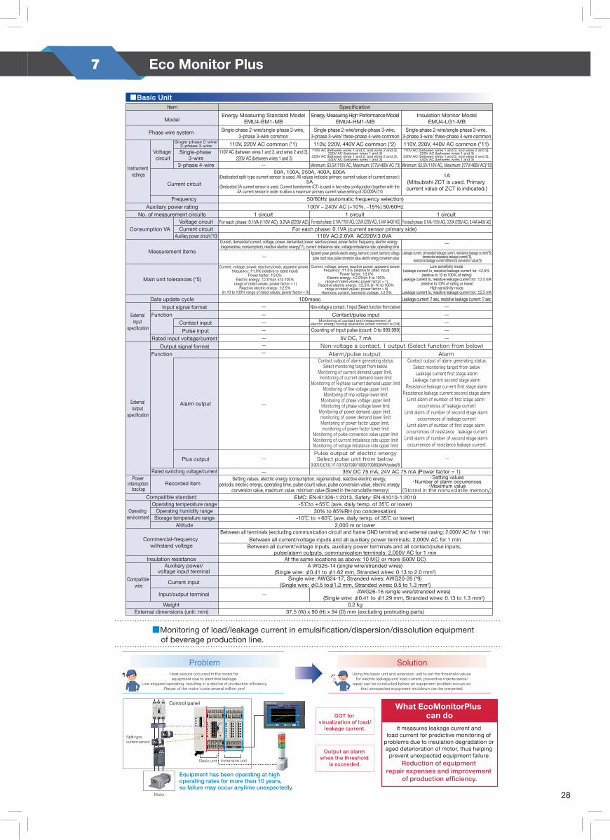
28
7 Eco Monitor Plus
8
Equipment has been operating at high operating rates for more than 10 years, so failure may occur anytime unexpectedly.
①Capable of measuring even extremely low levels of leakage current.
< Measurement of leakage current >
< Measurement of load current >
②Monitoring of equipment insulation degradation using Ior system
Alarm output + Current upper-/lower-limit monitoringUsing the contact output and current upper-/lower-limit monitoring function, the EcoMonitorPlus can detect abnormalities of production equipment before a problem actually occurs.
Production equipment
Insulation monitor unit (EMU4-LG1-MB)Leakage current resolution: 0.01 mA⇒Capable of measuring leakage current in equipment groups, such as motors.
Alarm output
Since leakage current (Io)is affected by the Ioc of the whole equipment, the Ior measurement is effective for insulation deterioration diagnosis.■Method of leakage current measurement(Io and Ior measurements)
When Ioc is low
≒
When Ioc is high
Ioc fluctuates on equipment with long wiring distance or inverter devices and filters.
Ior : Leakage current (resistive leakage current) which flows due to degraded insulationIoc: Leakage current (leakage current from electrostatic capacity) which flows even if the insulation condition is soundIo : Composite leakage current of Ior and Ioc (composition of vectors)
Ioc IorIorIo Ioc
TrCapacitor Resistance
{Ioc Io
IorIoc Io Io’
Ior Ior’
Amount of chance due to insulation deterioration=
Ioc Io Io’
Ior Ior’
Amount of change in Io
Amount of change in Ior <
Amount of change in Io
Amount of change in Ior
EMU4-HM1-MB
Want to use the EcoMonitorPlus for purposes other than energy saving!
Pro
duct Lineup
FeaturesS
pecificatio
nsN
ames of P
arts andE
xternal viewE
xternal viewC
onnectio
n C
onfig
urations
Sim
plified Com
parison of EcoM
onitor Prod
Application example
Monitoring of leakage current and load current
ProblemHeat seizure occurred in the motor for equipment due to electrical leakage.
Line stopped operating, resulting in a decline of production efficiency.Repair of the motor costs several million yen!
SolutionUsing the basic unit and extension unit to set the threshold values
for electric leakage and load current, preventive maintenance/repair can be conducted before an equipment problem occurs so
that unexpected equipment shutdown can be prevented.
Motor
Split-type current sensor
Basic unit Extension unit
Control panel
GOT for visualization of load/
leakage current.
Output an alarm when the threshold
is exceeded.
What EcoMonitorPlus can do
It measures leakage current and load current for predictive monitoring of
problems due to insulation degradation or aged deterioration of motor, thus helping
prevent unexpected equipment failure.Reduction of equipment
repair expenses and improvement of production efficiency.
■Monitoring of load/leakage current in emulsification/dispersion/dissolution equipment of beverage production line.
3. Specifications
9
Pro
duc
t Li
neup
Feat
ures
Sp
ecifi
catio
nsN
ames
of P
arts
and
Ext
erna
l vie
wE
xter
nal v
iew
Co
nnec
tion
Co
nfig
urat
ions
S
impl
ified
Com
paris
on o
f Ec
oMon
itor P
rod
Item
Voltage circuit
Current circuit
Frequency
Instrument ratings
External input
specification
External output
specification
Power interruption
backup
Model
Phase wire system Single-phase 2-wire/single-phase 3-wire, 3-phase 3-wire/ three-phase 4-wire common
Single-phase 2-wire/3-phase 3-wire
Single-phase 3-wire
110V, 220V, 440V AC common (*11)110V AC (between wires 1 and 2, and wires 2 and 3),
220V AC (between wires 1 and 3)220V AC (between wires 1 and 2, and wires 2 and 3),
440V AC (between wires 1 and 3)
ー
ー
ー
ー
ーーー
ーー
ーーーーー
ー
ー ー
ー
ー
ーInput signal format
Rated input voltage/current
Output signal format
Auxiliary power rating
Data update cycle Leakage current: 2 sec, resistive leakage current: 2 sec
Contact output of alarm generating statusSelect monitoring target from below.
Monitoring of current demand upper limit, monitoring of current demand lower limit
Monitoring of N-phase current demand upper limitMonitoring of line voltage upper limitMonitoring of line voltage lower limit
Monitoring of phase voltage upper limitMonitoring of phase voltage lower limit
Monitoring of power demand upper limit, monitoring of power demand lower limitMonitoring of power factor upper limit, monitoring of power factor lower limit
Monitoring of pulse conversion value upper limitMonitoring of current imbalance rate upper limitMonitoring of voltage imbalance rate upper limit
100msecNon-voltage a contact, 1 input (Select function from below)
Contact/pulse inputMonitoring of contact and measurement of
electric energy during operation (when contact is ON)
Counting of input pulse (count: 0 to 999,999)
5V DC, 7 mA
Alarm/pulse outputContact output of alarm generating status
Select monitoring target from belowLeakage current first stage alarm
Leakage current second stage alarmResistance leakage current first stage alarm
Resistance leakage current second stage alarmLimit alarm of number of first stage alarm
occurrences of leakage currentLimit alarm of number of second stage alarm
occurrences of leakage currentLimit alarm of number of first stage alarm occurrences of resistance leakage current
Limit alarm of number of second stage alarm occurrences of resistance leakage current
Alarm
35V DC 75 mA, 24V AC 75 mA (Power factor = 1)
Non-voltage a contact, 1 output (Select function from below)
Main unit tolerances (*5)
No. of measurement circuits
Consumption VA
3-phase 4-wire
110V AC:2.0VA AC220V:3.0VA
Alarm output
Contact input
Pulse input
Rated switching voltage/current
Recorded item
Plus output
Setting values, electric energy (consumption, regenerative), reactive electric energy, periodic electric energy, operating time, pulse count value, pulse conversion value, electric energy
conversion value, maximum value, minimum value (Stored in the nonvolatile memory)Compatible standard EMC: EN-61326-1:2013, Safety: EN-61010-1:2010
Operating temperature range -5℃to +55℃ (ave. daily temp. of 35℃ or lower)Operating humidity range 30% to 85%RH (no condensation)
Storage temperature range -10℃ to +60℃ (ave. daily temp. of 35℃ or lower)Altitude
Commercial-frequency withstand voltage
2,000 m or lower
Insulation resistance At the same locations as above: 10 MΩ or more (500V DC)Auxiliary power/
voltage input terminal
Input/output terminal
Current input
Between all current/voltage inputs and all auxiliary power terminals: 2,000V AC for 1 min
Pulse output of electric energySelect pulse unit from below.
0.001/0.01/0.1/1/10/100/1000/10000/100000(kWh/pulse)*6
Function
Function
Insulation Monitor ModelEMU4-LG1-MB
Specification
Measurement items
■Basic Unit
Between all current/voltage inputs, auxiliary power terminals and all contact/pulse inputs, pulse/alarm outputs, communication terminals: 2,000V AC for 1 min
A WG26-14 (single wire/stranded wires)(Single wire: φ0.41 to φ1.62 mm, Stranded wires: 0.13 to 2.0 mm2)
Single wire: AWG24-17, Stranded wires: AWG20-26 (*9)(Single wire: φ0.5 toφ1.2 mm, Stranded wires: 0.5 to 1.3 mm2)
WeightExternal dimensions (unit: mm) 37.5 (W) x 90 (H) x 94 (D) mm (excluding protruding parts)
0.2 kg
AWG26-16 (single wire/stranded wires)(Single wire: φ0.41 to φ1.29 mm, Stranded wires: 0.13 to 1.3 mm2)
Single-phase 2-wire/single-phase 3-wire, 3-phase 3-wire common
110V, 220V AC common (*1)
Energy Measuring Standard ModelEMU4-BM1-MB
Single-phase 2-wire/single-phase 3-wire, 3-phase 3-wire/ three-phase 4-wire common110V, 220V, 440V AC common (*2)
Energy Measuring High Performance ModelEMU4-HM1-MB
Minimum: 63.5V/110V AC, Maximum: 277V/480V AC (*3) Minimum: 63.5V/110V AC, Maximum: 277V/480V AC(*12)50A, 100A, 250A, 400A, 600A
(Dedicated split-type current sensor is used. All values indicate primary current values of current sensor.)5A
(Dedicated 5A current sensor is used. Current transformer (CT) is used in two-step configuration together with the 5A current sensor in order to allow a maximum primary current value setting of 30,000A) (*4)
1A(Mitsubishi ZCT is used. Primary current value of ZCT is indicated.)
110V AC (between wires 1 and 2, and wires 2 and 3), 220V AC (between wires 1 and 3)
110V AC (between wires 1 and 2, and wires 2 and 3), 220V AC (between wires 1 and 3)
220V AC (between wires 1 and 2, and wires 2 and 3), 440V AC (between wires 1 and 3)
50/60Hz (automatic frequency selection)100V – 240V AC (+10%, -15%) 50/60Hz
1 circuitFor each phase: 0.1VA (110V AC), 0.2VA (220V AC), 0.4VA (440V AC)
1 circuit
For each phase: 0.1VA (current sensor primary side)For each phase: 0.1VA (110V AC), 0.2VA (220V AC), 0.4VA (440V AC)
1 circuitFor each phase: 0.1VA (110V AC), 0.2VA (220V AC)
Current circuitVoltage circuit
Auxiliary power circuit (*10)
Current, voltage, power, reactive power, apparent power, frequency: ±1.0% (relative to rated input)
Power factor: ±3.0%Electric energy: ±2.0%(in 5 to 100%
range of rated values; power factor = 1)Reactive electric energy: ±2.5%
(in 10 to 100% range of rated values; power factor = 0)
Current, voltage, power, reactive power, apparent power, frequency: ±1.0% (relative to rated input)
Power factor: ±3.0%Electric energy: ±2.0%(in 5 to 100%
range of rated values; power factor = 1)Reactive electric energy: ±2.5% (in 10 to 100%
range of rated values; power factor = 0)Harmonic current, harmonic voltage: ±2.5%
Low sensitivity modeLeakage current Io, resistive leakage current Ior: ±2.5%
(relative to 10 to 100% of rating)Leakage current Io, resistive leakage current Ior: ±2.5 mA
(relative to 10% of rating or lower)High sensitivity mode
Leakage current Io, resistive leakage current Ior: ±2.5 mA
Current, demanded current, voltage, power, demanded power, reactive power, power factor, frequency, electric energy (regenerative, consumption), reactive electric energy(*7), current imbalance rate, voltage imbalance rate, operating time
Apparent power, periodic electric energy, harmonic current, harmonic voltage, pulse count value, pulse conversion value, electric energy conversion value
Leakage current, demanded leakage current, resistance leakage current(*8), demanded resistance leakage current(*8),
resistance leakage current difference conversion value(*8)
Between all terminals (excluding communication circuit and frame GND terminal) and external casing: 2,000V AC for 1 min
Energy Measuring Unit
Compatible wire
Operating environment
* 1 110V and 220V can be connected directly. Externally mounted voltage transformer (VT) for instrument is needed for voltages greater than those (primary voltage can be set to up to 11,000V, and secondary voltage can be set between 1 and 220V). For details, see the instruction manual.
* 2 110V, 220V and 440V can be connected directly. Externally mounted voltage transformer (VT) for instrument is needed for voltages greater than those (primary voltage can be set to up to 6,600V, and secondary voltage can be set between 1 and 220V). For details, see the instruction manual.
* 3 63.5V/110V – 277V/480V can be connected directly. An externally mounted voltage transformer (VT) for instrument is needed for voltages greater than those (primary voltage can be set to up to 6,600V, and secondary voltage can be set between 1 and 220V). For details, see the instruction manual.
* 4 The settable primary current when using the 5A current sensor is as follows:5A、6A、7.5A、8A、10A、12A、15A、20A、25A、30A、40A、50A、60A、75A、80A、100A、120A、150A、200A、250A、300A、400A、500A、600A、750A、800A、1000A、1200A、1500A、1600A、2000A、2500A、3000A、4000A、5000A、6000A、7500A、8000A、10000A、12000A、20000A、25000A、30000A(CT primary side can be set freely up to 30,000A. However, CT secondary side is fixed at 5A.)
* 5 Refer to the specifications of options (split-type current sensor, 5A current sensor) on page 13 for the current sensor error rates.* 6 Refer to the instruction manual for the detail on the setting of pulse unit.* 7 Measurements are conducted based on a setting other than 2-circuit measurement mode with single-phase 2-wire setting.* 8 It measures only in the case of Single-phase 2-wire, Single-phase 3-wire, 3-phase 3-wire. * 9 Recommended bar terminal: Nichihu TGV TC-1.25-11T.*10 Connected with optional units, it increases AC110V:4.5VA, AC220V:5.0VA.
Connected with display units, it increases AC110V:1.5VA, AC220V:2.0VA.*11 110V, 220V and 440V can be connected directly. Externally mounted voltage transformer (VT) for instrument is needed for voltages greater than those (maximum:600V AC). For details, see the instruction manual.*12 63.5V/110V – 277V/480V can be connected directly. Externally mounted voltage transformer (VT) for instrument is needed for voltages greater than those (maximum:600V AC). For details, see the instruction manual.
・Setting values・Number of alarm occurrences
・Maximum value(Stored in the nonuvolatile memory)

29
8 Eco WebServer


MDU Breaker
Ecomonitor
Power Meter
Eco Webserver
What’s e&eco-F@ctory?
Solution which enables visualization of production and energy saving to reduce production cost and energy cost
Mitsubishi Electric visualises activities to improve productivity with standard data management, and strongly supports energy conservation activity.
“Measurement/diagnosis”, “measures”, and “management” are assessed as a total life cycle, while each abundant results and know-how are linked to achieve an effect.
Energy-saving solution of e-F@ctory will be used for future management strategy more effectively.
Effect of “visible management” introduction• Compliance with Energy Conservation Law/ execution of enhanced enforcement
• Optimization of energy usage by FEMS (Factory Energy Management System)
• “Visualization” of energy-saving effect
• Permeation of energy-saving activity to organization
• Promotion of operational restructuring/ productivity improvement
Modbus RS485 & CC-Link
Communication available


