

MÖLLER-WEDEL OPTICAL GmbHRosengarten 10D-22880 Wedel, Germany
M EA SU RI NG EQU I PM E NT F OR LE NSES AN D OPTIC AL SYSTE MSM EA SU RI NG EQU I PM E NT F OR LE NSES AN D OPTIC AL SYSTE MS
Combinations and Accessories
Tel : +49 - 41 03 - 9 37 76 10Fax: +49 - 41 03 - 9 37 76 60
www.moeller-wedel-optical.come-mail: [email protected]
Combinations/Ord.-No. Applications
Combination 1 pos. focal length235 601 back focal length
Combination 2 pos. focal length235 602 neg. focal length
back focal length
Combination 3 pos. focal length235 603 neg. focal length
back focal lengthradius
Combination 4 pos. focal length235 604 neg. focal length
back focal lengthradiuswedge angle
Combination 5 pos. focal length235 605 neg. focal length
back focal lengthradiuswedge angleform deviation
Combination 6 radius235 606
Combination 7 wedge angle235 607
Combination 8 form deviation235 608
Accessories/Ord.-No.
Stand235 610
Stand with collimator235 620
Focus-Module235 630
Radius-Module235 640
Angle-Module 1235 645
Angle-Module 2235 647
Interferometer-Module235 650
Set of attachment achromats235 660
TV-set229 920
Two-axes tilting table235 670
Translation stage235 680
Reference elements(see page 8)
Radius display unit773 170 05
Ind i spens able for Qual i t y Cont ro l o f Opt i c s
M E L O S 5 3 0M E L O S 5 3 0
Prin
ted
in G
erm
any
235
600
E 05
/03

2Subject to change without prior notice
Measuring Equipment for Lenses and Optical Systems
The measurement combination MELOS 530 is the optimum solution for the comfortable and fast determination of effective focal length, back focal length, radii, wedge angles and surface form deviations. The big advantages to other systems are:
� Fast switching between the different measurement modes. Due to an im-proved set-up, no time-consuming change of the measuring system is necessary.
� Direct reading of the measurement results on a stand-alone display unit. All calculations necessary for the evaluation of positive and negative effective focal length measurements are carried out on the display unit. Results can be stored in a table and transferred to a computer for e.g. documentation purposes at a later time . The user is supported by the integrated help function. It allows even the inexperienced user to quickly get familiar with the usage of the instrument.
� Precise adjustment of the image planes, by monitor display of the reticle image.
� Easy conversion into an interferometric workstation for measurement of flatness, wavefront and sphericity by use of an inter-ferometric module.
� Full control over the measurement processby manual adjustment.
M E L O S 5 3 0M E L O S 5 3 0
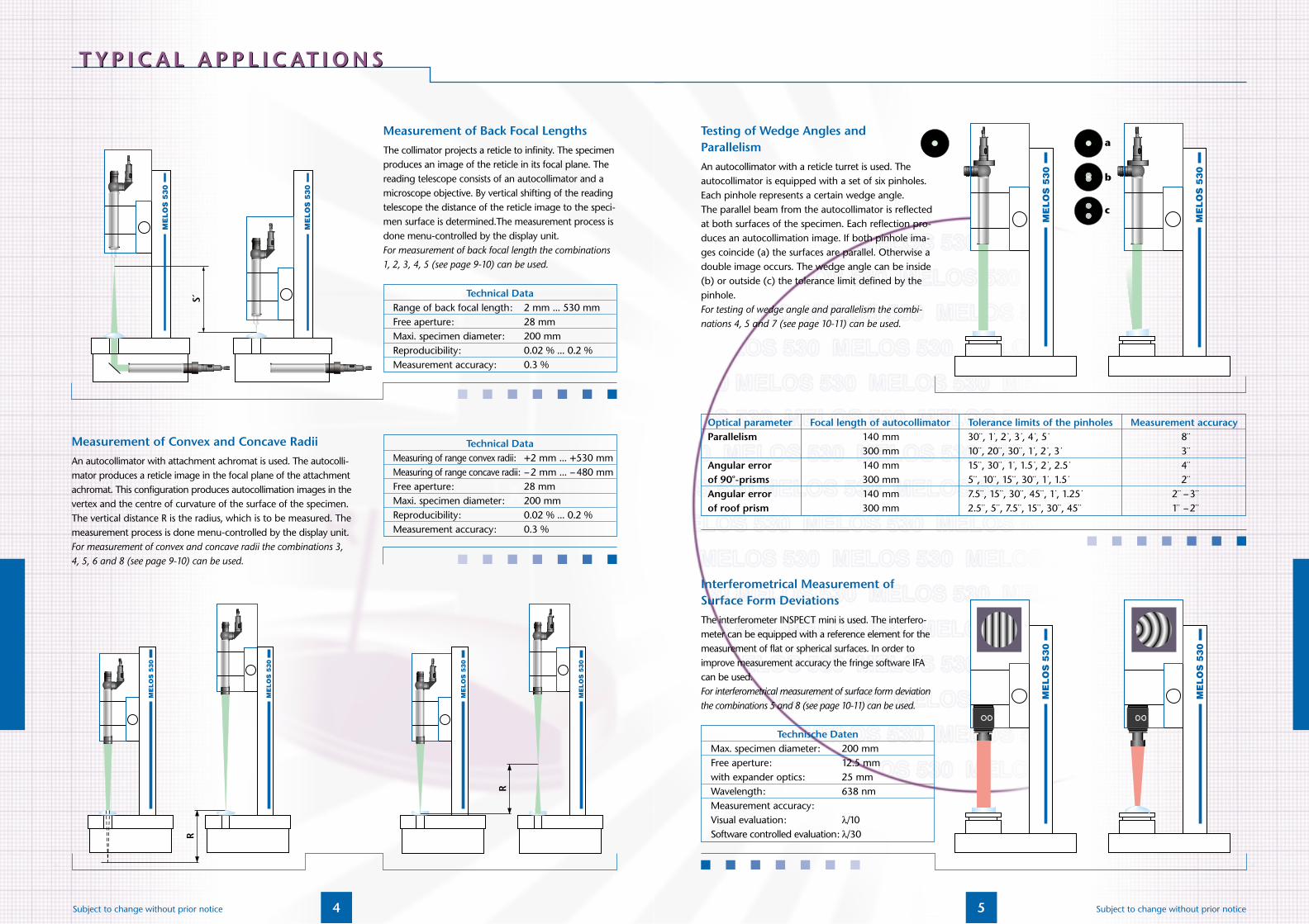
Measurement of Positive Focal Lengths
The collimator projects a reticle to infinity. The specimen pro-duces an image of the reticle in its focal plane. The size of thereticle image is determined solely by the known focal length ofthe collimator objective and the focal length of the specimen,which is to be measured. The measurement of the size of theprojected reticle with a reading telescope consisting of an auto-collimator and a microscope objective gives the focal length.The measurement process is done menu-controlled by the display unit.For measurement of positive focal lengths the combinations 1, 2, 3, 4, 5 (see page 9-10) can be used.
Measurement of Negative Focal Lengths
The collimator projects a reticle to infinity. The specimen pro-duces a virtual image of the reticle in the focal plane. Themeasurement of the size of the virtual reticle image with a rea-ding telescope consisting of an autocollimator and an attach-ment achromat gives the focal length. The measurement process is done menu-controlled by thedisplay unit.For measurement of negative focal lengths the combinations 2,3, 4, 5 (see Page 9-10) can be used.
3 Subject to change without prior notice
Technical DataRange of focal length: 5 mm ... 500 mmFree aperture: 28 mmMaximum specimen diameter: 200 mmReproducibility: 0.04 % ... 0.2 %Measurement accuracy: 0.3 %
Technical DataRange of focal length: –5 mm ... –580 mmFree aperture: 28 mmMaximum specimen diameter: 200 mmReproducibility: 0.04 % ... 0.2 %Measurement accuracy: 0.3 %
T Y P I C A L A P P L I C AT I O N ST Y P I C A L A P P L I C AT I O N S
5 Subject to change without prior notice
Testing of Wedge Angles and ParallelismAn autocollimator with a reticle turret is used. Theautocollimator is equipped with a set of six pinholes.Each pinhole represents a certain wedge angle.The parallel beam from the autocollimator is reflected at both surfaces of the specimen. Each reflection pro-duces an autocollimation image. If both pinhole ima-ges coincide (a) the surfaces are parallel. Otherwise a double image occurs. The wedge angle can be inside (b) or outside (c) the tolerance limit defined by the pinhole.For testing of wedge angle and parallelism the combi-nations 4, 5 and 7 (see page 10-11) can be used.
Technische DatenMax. specimen diameter: 200 mmFree aperture: 12.5 mmwith expander optics: 25 mmWavelength: 638 nmMeasurement accuracy:Visual evaluation: λ/10 Software controlled evaluation: λ/30
Interferometrical Measurement ofSurface Form DeviationsThe interferometer INSPECT mini is used. The interfero-meter can be equipped with a reference element for the measurement of flat or spherical surfaces. In order to improve measurement accuracy the fringe software IFA can be used.For interferometrical measurement of surface form deviationthe combinations 5 and 8 (see page 10-11) can be used.
Optical parameter Focal length of autocollimator Tolerance limits of the pinholes Measurement accuracyParallelism 140 mm 30¨, 1·, 2 ·, 3 ·, 4 ·, 5 · 8 ¨
300 mm 10¨, 20¨, 30¨, 1·, 2 ·, 3 · 3 ¨Angular error 140 mm 15¨, 30¨, 1·, 1.5 ·, 2 ·, 2.5 · 4 ¨of 90o-prisms 300 mm 5¨, 10¨, 15¨, 30¨, 1·, 1.5 · 2 ¨Angular error 140 mm 7.5¨, 15¨, 30¨, 45¨, 1·, 1.25 · 2 ¨ –3¨of roof prism 300 mm 2.5¨, 5 ¨, 7.5 ¨, 15¨, 30¨, 45¨ 1¨ –2¨
4Subject to change without prior notice
T Y P I C A L A P P L I C AT I O N ST Y P I C A L A P P L I C AT I O N S
Measurement of Back Focal LengthsThe collimator projects a reticle to infinity. The specimenproduces an image of the reticle in its focal plane. The reading telescope consists of an autocollimator and a microscope objective. By vertical shifting of the reading telescope the distance of the reticle image to the speci-men surface is determined.The measurement process is done menu-controlled by the display unit. For measurement of back focal length the combinations 1, 2, 3, 4, 5 (see page 9-10) can be used.
Measurement of Convex and Concave RadiiAn autocollimator with attachment achromat is used. The autocolli-mator produces a reticle image in the focal plane of the attachment achromat. This configuration produces autocollimation images in the vertex and the centre of curvature of the surface of the specimen. The vertical distance R is the radius, which is to be measured. The measurement process is done menu-controlled by the display unit.For measurement of convex and concave radii the combinations 3, 4, 5, 6 and 8 (see page 9-10) can be used.
Technical DataRange of back focal length: 2 mm ... 530 mmFree aperture: 28 mmMaxi. specimen diameter: 200 mmReproducibility: 0.02 % ... 0.2 %Measurement accuracy: 0.3 %
Technical DataMeasuring of range convex radii: +2 mm ... +530 mmMeasuring of range concave radii: –2 mm ... –480 mmFree aperture: 28 mmMaxi. specimen diameter: 200 mmReproducibility: 0.02 % ... 0.2 %Measurement accuracy: 0.3 %

6 7Subject to change without prior notice Subject to change without prior notice
Focus-Module
Consisting of focal length measurement module, intelligent display unit and TV-monitor (not shown).
Features of the measurement module: � Autocollimator with revolving nosepiece� Horizontal translation stage with fine adjustment:
measurement range: 20 mmresolution: 1 µmaccuracy: 3 µm
Features of the intelligent display unit:� Large LC-display with integrated software� Easy to use due to menu-based user interface � Integrated calculation of focal length, back focal
length and radius by direct reading of the length measurement systems
� Adjustable GO / NO-GO tolerances� Storing of the measurement results (in a table)� Data transfer to PC via RS-232 interface� Integrated help function
TV-set
TV-set consisting of:� Adapter for eyepiece� CCD-camera� B/W-monitor� Connection cables
Focal length mm Free ø mm Ord.-No.50 10.5 221 04890 16 221 051140 28 221 053200 28 221 055300 28 221 059500 28 221 063600 28 221 067
Description Ord.-No. Stand 235 610
Description Ord.-No. Stand with measuring collimator 235 620
Description Ord.-No.TV-set 229 920
Stand with measuring collimator
Features of the stand as listed under Ord.-No. 235 610. Additionally:� Collimator K200/40 with especially designed
reticle (combination of Siemens star and Porro test pattern)
� 90o folding mirror� Set of mechanical stops (support for specimen)
Stand
Features: � Vertical stand with excellent straightness and
high stability� One-hand operation for coarse and fine adjustment:
adjustment range: 530 mmfine adjustment resolution: 1 µm
� Integrated measurement system:measurement range: 530 mmresolution: 1 µmaccuracy: 3 µm
� Fixture for fast exchange of the measurement modules� Granite base with threads for tilting table and/or
XY-translation stage
Display unit Measuring head
Set of attachment achromats
Description Ord.-No. Radius-Module 235 640
Description Ord.-No.Angle-Module 1 235 645
Description Ord.-No. Angle-Module 2 235 647
AutocollimatorAKG 200/40/14.7
(A component of Ord.-No. 235 640).
AutocollimatorAKR 140/40/14.7 SWL
AKR with pinhole diaphragm turret (A component of Ord.-No. 235 645).
AutocollimatorAKR 300/40/14.7 SWL
AKR with pinhole diaphragm turret (A component ofOrd.-No. 235 647).
Description Ord.-No.Fokus-Module 235 630
C O M P O N E N T SC O M P O N E N T S

9 Subject to change without prior notice
Combination 1Measuring combination for measurement of positive focal lengths and back focal lengths.
Consisting of the 2 components:
Combination 2Measuring combination for measurement of positive and negative focal lengths as well as back focal lengths.
Consisting of the 3 components:
Technical DataMeasurement of pos. focal lengths see page 3Measurement of neg. focal lengths see page 3Measurement of back focal lengths see page 4
Technical DataMeasurement of pos. focal lengths see page 3Measurement of neg. focal lengths see page 3Measurement of back focal lengths see page 4
Measurement of concave/convex radii see page 4
Technical DataMeasurement of pos. focal lengths see page 3Measurement of back focal lengths see page 4
Combination 3Measuring combination for positive and negative focallengths, back focal lengths as well as concave, convex radii.
Consisting of the 4 components:
C O M B I N AT I O N SC O M B I N AT I O N S
Focus-Module Stand with collimator
Focus-Module Stand with collimator
Achromats
Focus-Module Stand with collimator
Achromats Translation stage
8Subject to change without prior notice
Description Ø Form deviation N.A. R/D Ord.-No.Transm. flat 1/2 ¨ λ/10 p-v — — 133 405 62Transm. sphere 1/2¨ λ/10 p-v 0.85 0.59 133 405 58Transm. sphere 1/2¨ λ/10 p-v 0.75 0.67 133 405 59Transm. sphere 1/2¨ λ/10 p-v 0.50 1.00 133 405 60Transm. sphere 1/2¨ λ/10 p-v 0.40 1.25 133 405 61Transm. flat 1¨ λ/10 p-v — — 133 405 57Transm. sphere 1¨ λ/10 p-v 0.75 0.59 133 405 51Transm. sphere 1¨ λ/10 p-v 0.67 0.67 133 405 52Transm. sphere 1¨ λ/10 p-v 0.55 1.00 133 405 53Transm. sphere 1¨ λ/10 p-v 0.40 1.25 133 405 54Transm. sphere 1¨ λ/10 p-v 0.28 1.25 133 405 55Transm. sphere 1¨ λ/10 p-v 0.15 1.25 133 405 56Expander optics Ø1/2¨ => Ø1¨ 133 405 66
Display module for radius measurement
Features:
� Zero setting in any position
� On-line display of vertical position for direct readingof radius
Description Ord.-No. Radius display module 773 170 05
Translation stage
Features:
� 5 mm translation in x- and y-direction� 1 turn of the adjustment screw corresponds to
0.25 mm translation
Interferometer-Module and reference elements
Interferometer-Module consists of INSPECT mini,adapter and fixture for reference elements.
Description Ord.-No. Translation stage 235 680
Two-axes tilting table
Features:
� ±4° angle of tilt in x- and y-axes
� 1 turn of the adjustment screw corresponds to 0.35o angle of tilt
Description Ord.-No. Two-axes tilting table 235 670
C O M P O N E N T SC O M P O N E N T S
10Subject to change without prior notice
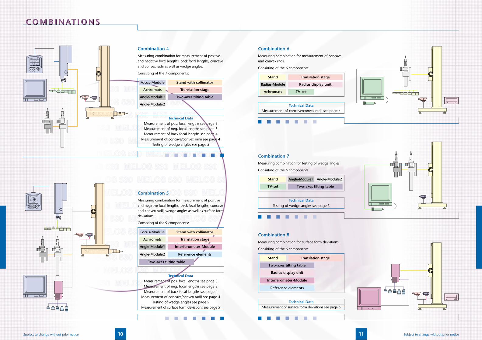
Technical DataMeasurement of pos. focal lengths see page 3Measurement of neg. focal lengths see page 3Measurement of back focal lengths see page 4
Measurement of concave/convex radii see page 4Testing of wedge angles see page 5
Combination 5Measuring combination for measurement of positive and negative focal lengths, back focal lengths, concaveand convex radii, wedge angles as well as surface formdeviations.
Consisting of the 9 components:
Technical DataMeasurement of pos. focal lengths see page 3Measurement of neg. focal lengths see page 3Measurement of back focal lengths see page 4
Measurement of concave/convex radii see page 4Testing of wedge angles see page 5
Measurement of surface form deviations see page 5
Combination 4Measuring combination for measurement of positive and negative focal lengths, back focal lengths, concaveand convex radii as well as wedge angles.
Consisting of the 7 components:
Angle-Module1 Two-axes tilting table
Achromats
Angle-Module2
Translation stage
Focus-Module Stand with collimator
Focus-Module Stand with collimator
Achromats Translation stage
Angle-Module1 Interferometer-Module
Angle-Module2 Reference elements
Two-axes tilting table
C O M B I N AT I O N SC O M B I N AT I O N S
11 Subject to change without prior notice
Combination 6Measuring combination for measurement of concave and convex radii.
Consisting of the 6 components:
Combination 7Measuring combination for testing of wedge angles.
Consisting of the 5 components:
Technical DataTesting of wedge angles see page 5
Combination 8Measuring combination for surface form deviations.
Consisting of the 6 components:
Technical DataMeasurement of surface form deviations see page 5
Technical DataMeasurement of concave/convex radii see page 4
Achromats TV-set
Radius-Module Radius display unit
Stand Translation stage
Stand Angle-Module1 Angle-Module2
TV-set Two-axes tilting table
Translation stageStand
Two-axes tilting table
Radius display unit
Interferometer-Module
Reference elements


