

Metal-Catalyzed Generation of Main-Group Electrophiles:
Mechanisms and Applications
vorgelegt von
Master of Science
Toni Tapio Metsänen
aus Viljakkala, Finnland
Von der Fakultät II - Mathematik und Naturwissenschaften
der Technischen Universität Berlin
zur Erlangung des akademischen Grades
Doktor der Naturwissenschaften
Dr. rer. nat.
genehmigte Dissertation
Promotionsausschuss:
Vorsitzender: Prof. Dr. Andreas Grohmann
Gutachter: Prof. Dr. Martin Oestreich
Gutachter: Prof. Dr. Warren E. Piers
Tag der wissenschaftlichen Aussprache: 28. April 2016
Berlin 2016

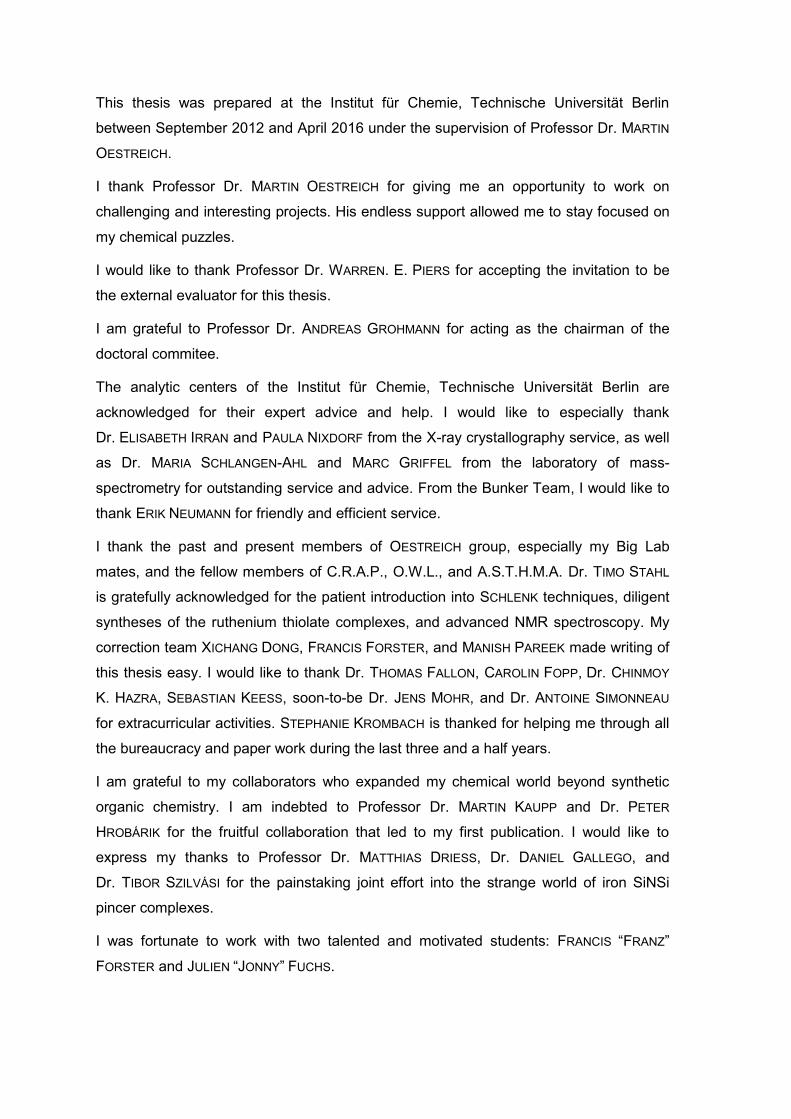
This thesis was prepared at the Institut für Chemie, Technische Universität Berlin
between September 2012 and April 2016 under the supervision of Professor Dr. MARTIN
OESTREICH.
I thank Professor Dr. MARTIN OESTREICH for giving me an opportunity to work on
challenging and interesting projects. His endless support allowed me to stay focused on
my chemical puzzles.
I would like to thank Professor Dr. WARREN. E. PIERS for accepting the invitation to be
the external evaluator for this thesis.
I am grateful to Professor Dr. ANDREAS GROHMANN for acting as the chairman of the
doctoral commitee.
The analytic centers of the Institut für Chemie, Technische Universität Berlin are
acknowledged for their expert advice and help. I would like to especially thank
Dr. ELISABETH IRRAN and PAULA NIXDORF from the X-ray crystallography service, as well
as Dr. MARIA SCHLANGEN-AHL and MARC GRIFFEL from the laboratory of mass-
spectrometry for outstanding service and advice. From the Bunker Team, I would like to
thank ERIK NEUMANN for friendly and efficient service.
I thank the past and present members of OESTREICH group, especially my Big Lab
mates, and the fellow members of C.R.A.P., O.W.L., and A.S.T.H.M.A. Dr. TIMO STAHL
is gratefully acknowledged for the patient introduction into SCHLENK techniques, diligent
syntheses of the ruthenium thiolate complexes, and advanced NMR spectroscopy. My
correction team XICHANG DONG, FRANCIS FORSTER, and MANISH PAREEK made writing of
this thesis easy. I would like to thank Dr. THOMAS FALLON, CAROLIN FOPP, Dr. CHINMOY
K. HAZRA, SEBASTIAN KEESS, soon-to-be Dr. JENS MOHR, and Dr. ANTOINE SIMONNEAU
for extracurricular activities. STEPHANIE KROMBACH is thanked for helping me through all
the bureaucracy and paper work during the last three and a half years.
I am grateful to my collaborators who expanded my chemical world beyond synthetic
organic chemistry. I am indebted to Professor Dr. MARTIN KAUPP and Dr. PETER
HROBÁRIK for the fruitful collaboration that led to my first publication. I would like to
express my thanks to Professor Dr. MATTHIAS DRIESS, Dr. DANIEL GALLEGO, and
Dr. TIBOR SZILVÁSI for the painstaking joint effort into the strange world of iron SiNSi
pincer complexes.
I was fortunate to work with two talented and motivated students: FRANCIS “FRANZ”
FORSTER and JULIEN “JONNY” FUCHS.

I would like to thank all my former colleagues who have helped me in the past. I would
have never made it without you. I thank Professor Dr. P. ANDREW EVANS for the
interesting year and a half I got to spend in Liverpool. Especially, I thank my fellow G20
survivors Dr. TOMASS BAIKSTIS, Dr. REBECCA GRANGE, Dr. SERGIO MARATO, Dr. SHANE
MCKENNA, THOMAS NATION, Dr. RYAN O’CONNOR, Dr. STEPHEN “MIGHTY” OJO,
Dr. SAMUEL OLIVER, BARBARA VARDA, and Dr. STEPHANIE YIP. I also thank Professor Dr.
PETRI PIHKO for his continued support. Special thanks to the members of the PIHKO
group who, among many other things, showed me how to correctly assemble a short-
plug distillation apparatus. I need to thank ANNUKKA ENERVI, MIRA HAVUKAINEN, and
LAURA PITKÄJÄRVI who helped me get through Physical Chemistry 1.
I thank all my friends and family who have kept supporting me through the years.
Special thanks to ANTTI N. T. SALMINEN for designing the covers of this thesis and MIKKO
P. PUULA for the design of the Organometallics cover.
Most of all, I thank LAURA and ELIEL. Without you, I would be completely lost.

Ei unelma valoa vaadi
vaan rohkeutta
”Viestintuoja”
Viimeinen Atlantis, 2010
Stam1na
Schönke dan
kiitokset humpasta
“Kiitokset Humpasta”
Pahviche, 2002
Eläkeläiset


PUBLICATIONS
Parts of this work have been published:
[1] “Insight into the Mechanism of Carbonyl Hydrosilylation Catalyzed by
Brookhart’s Cationic Iridium(III) Pincer Complex”,
T. T. Metsänen, P. Hrobárik, H. F. T. Klare, M. Kaupp, M. Oestreich,
J. Am. Chem. Soc. 2014, 136, 6912–6915.
[2] “Temperature-Dependent Chemoselective Hydrosilylation of Carbon Dioxide
to Formaldehyde or Methanol Oxidation State”,
T. T. Metsänen and M. Oestreich,
Organometallics 2015, 34, 543–546.
[3] “Peripheral mechanism of a carbonyl hydrosilylation catalysed by an SiNSi
iron pincer complex”,
T. T. Metsänen, D. Gallego, T. Szilvási, M. Driess, M. Oestreich,
Chem. Sci. 2015, 6, 7143–7149.
ORAL PRESENTATIONS
[1] T. T. Metsänen, “Insight into the Mechanism of Carbonyl Hydrosilylation
Catalyzed by Brookhart’s Cationic Iridium(III) Pincer Complex”,
17th International Symposium on Silicon Chemistry (ISOS), Berlin, 3–8 August
2014.
[2] T. T. Metsänen, “Cooperative Si–H bond activation: generation of electrophilic
silicon for carbon dioxide reduction”,
UniCat meeting, Berlin, December 12th 2013.
POSTER PRESENTATIONS
[1] T. T. Metsänen, D. Gallego, T. Szilvási, M. Driess, and M. Oestreich,
“Peripheral Mechanism of a Carbonyl Hydrosilylation Catalyzed by an SiNSi
Iron Pincer Complex”,
ICIQ-UniCat Summer School in Berlin (Germany), July 6–9 2015.


ZUSAMMENFASSUNG
Der erste Teil dieser Dissertation beschäftigt sich mit den Mechanismen
metallkatalysierter Aktivierungen von Hauptgruppenhydriden. Der von BROOKHART
entwickelte Iridium(III)-POCOP-Pincerkomplex kann als LEWIS-Säure Hydrosilane
aktivieren. Die Silylgruppe wird durch einen SN2-Si-Mechanismus übertragen, wie
bereits für Bor-LEWIS-Säuren gezeigt. Der anschließende Hydridtransfer weicht
allerdings vom vorgeschlagenen Mechanismus ab. Kontrollexperimente zeigten, dass
das Iridiumdihydrid, welches als Hydriddonor vermutet wurde, kein Hydrid auf das
Kohlenstoffatom des Silylcarboxoniumions überträgt. Im Gegensatz dazu wurde in
Anwesenheit eines Überschusses an Hydrosilan das Silylcarboxoniumion leicht zum
gewünschten Silylether reduziert. Durch Kombination spektroskopischer
Untersuchungen und quantenchemischer Berechnungen wurden neue Iridium-
trihydridkomplexe als de facto Hydriddonoren identifiziert, die durch die Koordination
überschüssigen Hydrosilans an das Dihydrid entstehen.
Die Untersuchung der durch den Eisen(0)-SiNSi-Pincerkomplex katalysierten
Hydrosilylierung zeigte einen unbekannten Mechanismus. Der Eisen(0)-Komplex wurde
als Präkatalysator identifiziert, welcher den aktiven Eisen(II)-Komplex nach oxidativer
Addition des Hydrosilans bildet. Kinetische und stöchiometrische Experimente sowie
Deuteriummarkierungsexperimente und der stereochemische Verlauf an einem silicium-
stereogenen Hydrosilan schließen alle bekannten Mechanismen aus. Somit wurde ein
neuer, durch DFT-Berechnungen gestützter peripherer Mechanismus vorgeschlagen, in
dem die Reaktion außerhalb der äußeren Sphere stattfindet, in der Peripherie des
Metallzentrums. Das Siliciumatom der am Eisen(II)-Zentrum gebundenen Silylgruppe
agiert als LEWIS-Säure in der Carbonylaktivierung.
Der zweite Teil dieser Arbeit beschreibt Anwendungen von Rutheniumthiolatkomplexen
in der katalytischen kooperativen Aktivierung von Hauptgruppenhydriden. Hierbei wurde
die Reduktion von CO2 mit Hydrosilanen, -boranen und -alanen ermöglicht. Die
Hydrosilylierung liefert abhängig von der Reaktionstemperatur selektiv Bis(silyl)acetale
bzw. silyliertes Methanol. Die Hydroborierung reduziert selektiv in die Methanol-
oxidationsstufe. Die rutheniumthiolatkatalysierte Hydroaluminierung reduziert CO2 bei
Raumtemperatur mit Bevorzugung der Formaldehydoxidationsstufe.
Die Al–H-Bindungsaktivierung durch den Rutheniumthiolatkomplex fand in der
defluorierenden FRIEDEL–CRAFTS-Alkylierung elektronenreicher Aromaten Anwendung.
Die Reaktion verläuft bei Raumtemperatur unter Bildung der gewünschten
Diarylmethane in guter Regioselektivität.

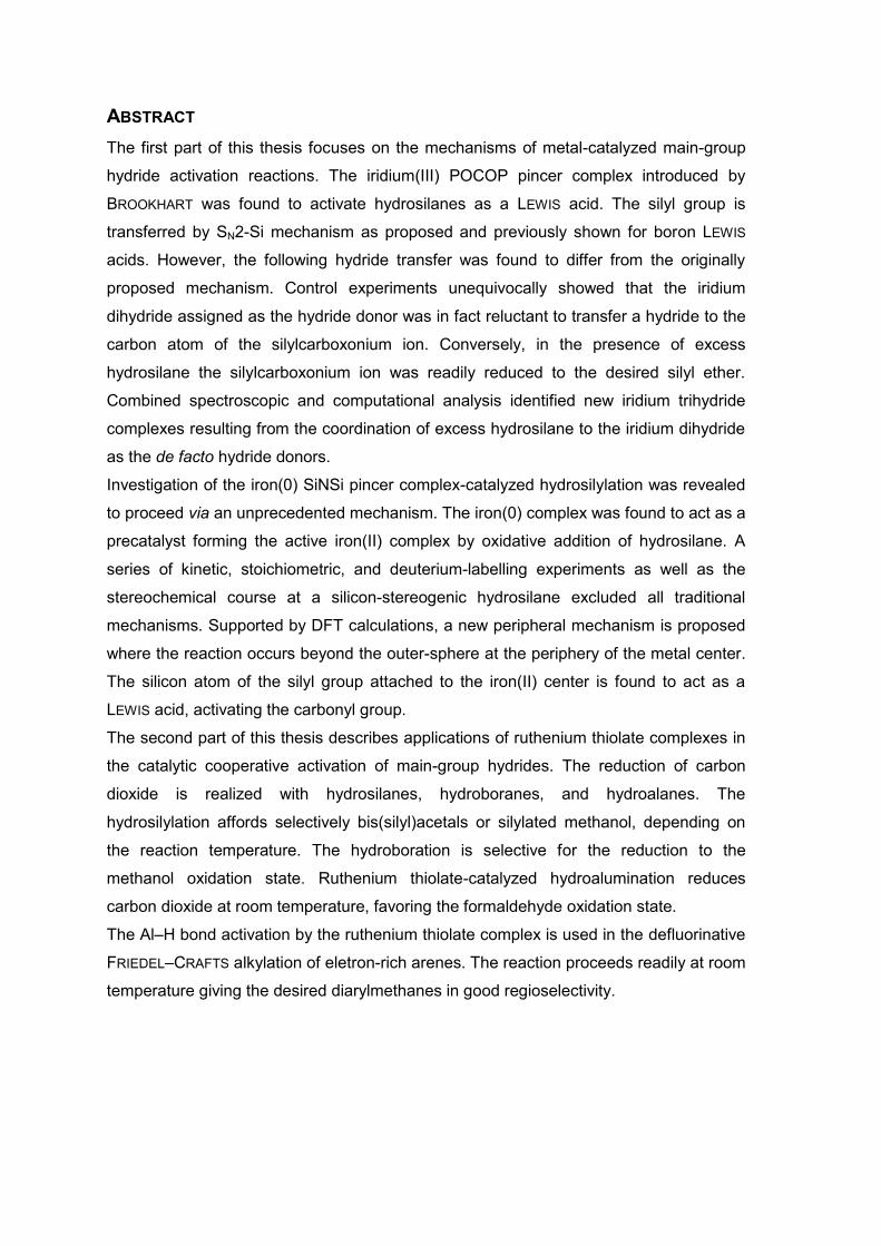
ABSTRACT
The first part of this thesis focuses on the mechanisms of metal-catalyzed main-group
hydride activation reactions. The iridium(III) POCOP pincer complex introduced by
BROOKHART was found to activate hydrosilanes as a LEWIS acid. The silyl group is
transferred by SN2-Si mechanism as proposed and previously shown for boron LEWIS
acids. However, the following hydride transfer was found to differ from the originally
proposed mechanism. Control experiments unequivocally showed that the iridium
dihydride assigned as the hydride donor was in fact reluctant to transfer a hydride to the
carbon atom of the silylcarboxonium ion. Conversely, in the presence of excess
hydrosilane the silylcarboxonium ion was readily reduced to the desired silyl ether.
Combined spectroscopic and computational analysis identified new iridium trihydride
complexes resulting from the coordination of excess hydrosilane to the iridium dihydride
as the de facto hydride donors.
Investigation of the iron(0) SiNSi pincer complex-catalyzed hydrosilylation was revealed
to proceed via an unprecedented mechanism. The iron(0) complex was found to act as a
precatalyst forming the active iron(II) complex by oxidative addition of hydrosilane. A
series of kinetic, stoichiometric, and deuterium-labelling experiments as well as the
stereochemical course at a silicon-stereogenic hydrosilane excluded all traditional
mechanisms. Supported by DFT calculations, a new peripheral mechanism is proposed
where the reaction occurs beyond the outer-sphere at the periphery of the metal center.
The silicon atom of the silyl group attached to the iron(II) center is found to act as a
LEWIS acid, activating the carbonyl group.
The second part of this thesis describes applications of ruthenium thiolate complexes in
the catalytic cooperative activation of main-group hydrides. The reduction of carbon
dioxide is realized with hydrosilanes, hydroboranes, and hydroalanes. The
hydrosilylation affords selectively bis(silyl)acetals or silylated methanol, depending on
the reaction temperature. The hydroboration is selective for the reduction to the
methanol oxidation state. Ruthenium thiolate-catalyzed hydroalumination reduces
carbon dioxide at room temperature, favoring the formaldehyde oxidation state.
The Al–H bond activation by the ruthenium thiolate complex is used in the defluorinative
FRIEDEL–CRAFTS alkylation of eletron-rich arenes. The reaction proceeds readily at room
temperature giving the desired diarylmethanes in good regioselectivity.


TABLE OF CONTENTS


TABLE OF CONTENTS
THEORETICAL PART I
1 INTRODUCTION 1
1.1 Mechanisms of Metal-Catalyzed Generation of Group 13 Electrophiles 3
1.1.1 Inner-Sphere Mechanisms 3
1.1.2 Outer-Sphere Mechanisms 13
1.2 Mechanisms of Metal-Catalyzed Generation of Group 14 Electrophiles 18
1.2.1 Inner-Sphere Mechanisms 18
1.2.2 Outer-Sphere Mechanisms 29
1.2.2.1 Cooperative Activation Mechanisms 29
1.2.2.2 LEWIS-Acid Activation Mechanisms 33
1.3 Objective 41
2 MECHANISTIC INVESTIGATION INTO BROOKHART’S IRIDIUM(III) POCOP
PINCER COMPLEX-CATALYZED CARBONYL HYDROSILYLATION
43
2.1 Introduction 43
2.2 Mechanistic Investigation into Iridium POCOP Pincer Complex-
Catalyzed Carbonyl Carbonyl Hydrosilylation
47
2.2.1 Hydrosilylation Using Silicon-Stereogenic Hydrosilanes 47
2.2.2 Identification of the Hydride Source 50
3 MECHANISTIC INVESTIGATION INTO IRON(II) SINSI PINCER COMPLEX-
CATALYZED CARBONYL HYDROSILYLATION
65
3.1 Synthesis of Iron(0) SiNSi Pincer Complex and Application in the
Carbonyl Hydrosilylation
65
3.2 Mechanistic Investigation into Iron SiNSi Pincer Complex-Catalyzed
Carbonyl Hydrosilylation
66
4 SUMMARY 81

THEORETICAL PART II
5 CARBON DIOXIDE REDUCTION 85
5.1 Reduction of Carbon Dioxide into Formate Oxidation State 85
5.2 Reduction of Carbon Dioxide into Formaldehyde Oxidation State 87
5.3 Reduction of Carbon Dioxide into Methanol Oxidation State 90
5.4 Reduction of Carbon Dioxide into Methane 93
5.5 Summary 95
5.6 Ruthenium Thiolate-Catalyzed Hydrosilylation of Carbon Dioxide 95
6 FUNCTIONALIZATION OF C–F BONDS 101
6.1 Introduction 101
6.2 Catalytic Generation of Alumenium Ions by Cooperative Al–H Bond
Activation in Defluorinative FRIEDEL–CRAFTS Alkylation
106
7 SUMMARY 115
EXPERIMENTAL PART
1 GENERAL INFORMATION 119
2 GENERAL PROCEDURES 129
2.1 General Procedure for the Hydrosilylation of Ketones Catalyzed by
Brookhart’s Iridium(III) Pincer Complex 73+ (GP1)
129
2.2 General Procedure for the Reductive Si–O Bond Cleavage of
Silyl Ethers (GP 2)
129
2.3 General Procedure for the Stoichiometric Reaction of Iron(0)
complex 124 with Hydrosilanes 23 (GP 3)
130
2.4 Carbon Dioxide Reduction (GP 4) 130
2.5 Ruthenium Thiolate-Catalyzed Hydrodefluorinative FRIEDEL–CRAFTS
Alkylation (GP 5)
130

3 DESCRIPTION OF EXPERIMENTS 133
3.1 Mechanistic Investigations 133
3.1.1 Iridium(III) POCOP Pincer Complex-Catalyzed Carbonyl Hydrosilylation 133
3.1.2 Iron SiNSi Pincer Complex-Catalyzed Carbonyl Hydrosilylation 156
3.2 Applications of Catalytically Generated Main-Group Electrophiles 174
3.2.1 Hydrosilylation of Carbon Dioxide Catalyzed by Ruthenium Thiolate
Complex
174
3.2.2 Catalytic Generation of Alumenium Ions by Cooperative Al–H Bond
Activation in Defluorinative FRIEDEL–CRAFTS Alkylation
184
APPENDIX
A1 X-RAY CRYSTAL STRUCTURE DATA 193
A1.1 Molecular Structure of 107e 193
A1.2 Molecular Structure of 107a 194
A2 ABBREVIATIONS 195
A3 BIBLIOGRAPHY 199
A4 CURRICULUM VITAE 215


THEORETICAL PART I
MECHANISMS


1 Introduction 1
1 INTRODUCTION
Metal-catalyzed generation of main-group electrophiles gives access to some of the most
reactive intermediates at a synthetic chemists deposit.[1,2] The ability to generate variety of
highly electrophilic main-group LEWIS acids under mild catalytic conditions opens unique
reactivity. The mechanisms of metal-catalyzed main-group hydride activation can be divided
into two main categories according to the related dihydrogen activation mechanisms:[3] inner-
and outer-sphere (Scheme 1.1). In the inner-sphere mechanisms both the main-group
element reagent and the substrate are in contact with the metal center whereas in the outer-
sphere mechanisms only one of the two is directly in contact with the metal. A typical inner-
sphere mechanism involves oxidative addition of the main-group hydride to the metal center
(I+II→III→IV). Alternatively, dihydro compound V can undergo two consecutive oxidative
additions to form an M=E bond containing complex VII. σ-Bond metathesis mechanism
involves the activation of E–H bond via concerted four-centered transition state IX‡.
Mechanisms including coordination of the substrates prior to the σ-bond metathesis
(XII→XIII‡→XIV) are classified as σ-complex-assisted metathesis. The outer-sphere
mechanisms typically involve ionic intermediates whereas the reactions occuring at the inner
sphere of the metal are usually charge neutral.[4] Cooperative activation of E–H bonds via
σ-bond metathesis-type transition state XVI‡ gives metal hydride XVII. Coordination of main-
group hydride I to a LEWIS-acidic metal complex II activates the main-group element for
nucleophilic attack by a LEWIS-basic substrate (LB). Finally, the E–H bond can be activated
by LEWIS bases (I+X→XXI).
[1]
For the synthesis and reactivity of boron cations, see: a) K. Kölle, H. Nöth, Chem. Rev. 1985,
85, 399–418; b) W. E. Piers, S. C. Bourke, K. D. Conroy, Angew. Chem. 2005, 117, 5142–
5163; Angew. Chem. Int. Ed. 2005, 44, 5016–5036; for aluminum, gallium, and indium cations,
see: c) D. A. Atwood, Coord. Chem Rev. 1998, 176, 407–430. [2]
For the synthesis and reactivity of silylium ions, see: a) A. Schulz, A. Villinger, Angew. Chem.
2012, 124, 4602–4604; Angew. Chem. Int. Ed. 2012, 51, 4526–4528; b) H. F. T. Klare, M.
Oestreich, Dalton Trans. 2010, 39, 9176–9184; for germylium ions, see: c) A. Schäfer, M.
Reißmann, S. Jung, A. Schäfer, W. Saak, E. Bredler, T. Müller, Organometallics 2013, 32,
4713–4722; for stannylium ions, see: d) A. Schäfer, W. Saak, D. Haase, T. Müller, J. Am.
Chem. Soc. 2011, 133, 14562–14565; for selected reviews, see: e) V. Y. Lee, A. Sekiguchi,
Organometallic Compounds of Low-Coordinate Si, Ge, Sn and Pb; Wiley, Chichester, 2010; f)
V. Y. Lee, A. Sekiguchi, Acc. Chem. Res. 2007, 40, 410–419; g) T. Müller, Adv. Organomet.
Chem. 2005, 53, 155–215. [3]
a) O. Eisenstein, R. H. Crabtree, New J. Chem. 2013, 37, 21–27; b) A. Comas-Vives, G.
Ujaque, A. Lledós, Adv. Inorg. Chem. 2010, 62, 231–260; c) R. M. Bullock, Chem. Eur. J.
2004, 10, 2366–2374; d) R. Noyori, M. Yamakawa, S. Hashiguchi, J. Org. Chem. 2001, 66,
7931–7944. [4]
M. Iglesias, F. J. Fernández-Alvarez, L. A. Oro, ChemCatChem 2014, 6, 2486–2489.

2 THEORETICAL PART I
Scheme 1.1: Classification of E–H bond activation mechanisms.
The following chapters give an overview of the various mechanisms of the E–H bond
activation focusing on the catalytically relevant pathways. The majority of the detailed
mechanistic investigations have been conducted regarding catalytic generation of silicon and
boron electrophiles. Presumably due to scarce number of methodologies of the generation of
other main-group electrophiles, the mechanisms for hydrogermane, -stannane, and -alane
activation are not as well understood. Chapter 1.1 presents the established mechanisms of
metal-catalyzed generation of group 13 electrophiles, focusing on hydroborane activation.
The isolated examples of hydroalane activation will be mentioned together with analogous
hydroborane mechanisms. In addition to hydroboranes, representative examples of
mechanisms involving other sources of boron electrophiles are described. Chapter 1.2
centers around generation of silicon electrophiles and mainly on the activation of
hydrosilanes. The hydrogermane and -stannane activation mechanisms are discussed
together with their silicon counterparts.

1 Introduction 3
1.1 Mechanisms of Metal-Catalyzed Generation of Group 13
Electrophiles
Organoboron reagents are widely used in organic chemistry.[5] Metal-catalyzed activation of
hydroboranes opens complementary reactivity to the stoichiometric and uncatalyzed
reactions. The mechanisms of these transformations are often relatively well understood. In
addition to boron, the availability and high reactivity made the use of aluminum reagents
common in organic chemistry.[6] However, most of the classic organoaluminum chemistry is
stoichiometric and only a few metal-catalyzed reactions have been developed and the
detailed mechanisms of these reactions are mostly unknown.
1.1.1 Inner-Sphere Mechanisms
In 1985 NÖTH investigated the hydroboration of alkenes in the presence of carbonyl
groups.[7] The hydroborane 2a was shown to hydroborate the carbonyl group in an
uncatalyzed reaction. Addition of 0.05 mol % WILKINSON’s catalyst (5) gave 4 with good
chemoselectivity, showing that the metal catalyst not only increases the reactivity of
hydroboranes, but can also give access to complementary products (Scheme 1.2).
Scheme 1.2: Hydroboration of hex-5-en-2-one (1) with catecholborane (2a).
[5]
a) N. Miyaura, Top. Curr. Chem. 2002, 219, 11–59; b) N. Miyaura, A. Suzuki, Chem. Rev.
1995, 95, 2457–2483; c) A. Suzuki, Acc. Chem. Rev. 1982, 15, 178–184; d) A. Pelter, Chem.
Soc. Rev. 1982, 11, 191–225 [6]
a) M. Dahlmann, M. Lautens in Catalytic Heterofunctionalization (Eds.: A. Togni, H.
Grützmacher), Wiley-VCH, Chichester, 2001; b) Reduction by the Alumino- and Borohydrides
in Organic Synthesis, 2nd
edition (Ed.: J. Seyden-Penne), Wiley-VCH, New York, 1997. [7]
D. Männing, H. Nöth, Angew. Chem. 1985, 97, 854–855; Angew. Chem. Int. Ed. Engl. 1985,
24, 878–879.

4 THEORETICAL PART I
The mechanism of the reaction was proposed to initiate after dissociation of a phosphine
ligand 6a to afford complex 7 (Scheme 1.3). Oxidative addition of the hydroborane 2 to the
rhodium(I) center gives the key intermediate 8. Dissociation of a second phosphine ligand 6a
and coordination of the alkene followed by alkene insertion to the Rh–H bond and
recoordination of the phosphine ligand leads to the alkyl complex (8→XXIII→XXIV).
Reductive elimination releases the alkylborane XXV and the catalyst 7. The mechanism was
later supported by a careful mechanistic investigations by EVANS.[8] Additionally, deuterium-
labeling studies suggested that the insertion into the Rh–H bond is reversible
(XXIII ⇋ XXIV).
Scheme 1.3: Proposed mechanisms of alkene hydroboration catalyzed by WILKINSON’s catalyst.
[8]
a) D. A. Evans, G. C. Fu, J. Org. Chem. 1990, 55, 2280–2282; b) D. A. Evans, G. C. Fu, B. A.
Anderson, J. Am. Chem. Soc. 1992, 114, 6679–6685.

1 Introduction 5
The mechanistic studies by EVANS were later questioned by BURGESS, MARDER, and
BAKER.[9] The authors conducted a series of stoichiometric experiments, isolated several
decomposition products, and repeated some of the deuterium-labeling experiments of
EVANS. BURGESS, MARDER, and BAKER argued that the hydroboration catalyzed by
WILKINSON’s catalyst is significantly more complicated than proposed and that many of the
decomposition products formed during the reaction might be catalytically active as well. The
authors showed that the hydroborane 2a used for the reaction was partially decomposed
under the catalytic conditions forming highly reactive BH3 (2b) that could also act as the
reducing agent.[10] Based on experiments with excess phosphine 6a, a revised mechanism
was proposed where the alkene insertion takes place without phosphine dissociation
(8→XXVI→XXIV).
In addition to the experimental investigations, the reaction has also been studied
computationally but no consensus has been reached by DFT calculations either.[11]
MOROKUMA carried out extensive calculations on all the proposed mechanisms and
supported the associative mechanism in that the mechanism proceeding via XXVI was the
lowest in energy. However, the insertion to the Rh–B bond (XXVI→XXVII) instead of Rh–H
(XXVI→XXIV) was found to be the preferred mechanism.
Nickel-catalyzed hydroalumination was proposed to proceed via an analogous mechanism
(Scheme 1.4).[12] The oxidative insertion of the hydroalane 9 to the nickel XXVIII gives the
nickel(II) hydride XXIX. Alkene XXII insertion to the Ni–H bond followed by reductive
elimination gives the hydroaluminated product XXXI and regenerates the nickel(0) XXVIII.
[9]
K. Burgess, W. A. van der Donk, S. A. Wescott, T. B. Marder, R. T. Baker, J. C. Calabrese, J.
Am. Chem. Soc. 1992, 114, 9350–9359. [10]
This so-called “Trojan-horse mechanism” was proposed for other hydroboration reactions: a)
K. Burgess, M. Jaspars, Tetrahedron Lett. 1993, 34, 6813–6816; b) S. Harder, J. Spielmann,
J. Organomet. Chem. 2012, 698, 7–14. [11]
a) D. G. Musaev, A. M. Mebel, K. Morokuma, J. Am. Chem. Soc. 1994, 116, 10693–10702; b)
A. E. Dorigo, P. von Ragué Schleyer; Angew. Chem. 1995, 107, 108–111; Angew. Chem. Int.
Ed. Engl. 1995, 34, 115–118; c) C. Widauer, H. Grützmacher, T. Ziegler, Organometallics
2000, 19, 2097–2107. [12]
a) J. J. Eisch, K. C. Fichter, J. Am. Chem. Soc. 1974, 96, 6815–6817; b) J. J. Eisch, S. R.
Sexsmith, K. C. Fichter, J. Organomet. Chem. 1990, 382, 273–293; c) J. J. Eisch, X. Ma, M.
Singh, G. Wilke, J. Organomet. Chem. 1997, 527, 301–304.

6 THEORETICAL PART I
Scheme 1.4: Nickel-catalyzed hydroalumination of alkenes.
Hydroboration of alkynes typically occurs stereospecifically in syn-fashion through similar
mechanisms as proposed for alkenes.[13] In 2000 MIYAURA presented a rhodium-catalyzed
method to selectively obtain (E)-vinyl boranes through a proposed vinylidene intermediate
XXXIV (Scheme 1.5).[14] The insertion of the metal center to the alkynyl Csp–H bond and
isomerization gives the vinylidene complex XXXIV. Following oxidative addition of
hydroborane, 1,2-boryl migration and reductive elimination furnish the (E)-vinyl borane
(XXXV→XXXVI→XXXVII). The catalytic system reported by MIYAURA required stoichiometric
base to inhibit the conventional syn-hydroboration. In 2012, LEITNER overcame this
restriction by a PCNCP ruthenium pincer complex that allowed for the synthesis of the
E-vinyl borane XXXVII without added base. The proposed mechanism was complementary
to the MIYAURA mechanism.[15]
[13]
I. Beletskaya, A. Pelter, Tetrahedron 1997, 53, 4957–5026. [14]
T. Ohmura, Y. Yamamoto, N. Miyaura, J. Am. Chem. Soc. 2000, 122, 4990–4991. [15]
C. Gunanathan, M. Hölscher, F. Pan, W. Leitner, J. Am. Chem. Soc. 2012, 134, 14349–14352.

1 Introduction 7
Scheme 1.5: Formal trans-hydroboration via a vinylidene intermediate ([M] = [RhCl(iPr3P)n]).
As evident by the mechanism in Scheme 1.5, the methods reported by MIYAURA and LEITNER
are limited to terminal alkynes. The trans-hydroboration of internal alkynes reported by
FÜRSTNER[16,17] could not proceed via the vinylidene intermediate XXXIV and a new
mechanism was proposed to explain the observed selectivity (Scheme 1.6). The alkyne was
proposed to coordinate to the cationic ruthenium center replacing one of the acetonitrile (10)
ligands. Dissociation of two more acetonitriles and coordination of hydroborane gives
complex XXXIX+. Hydride transfer from boron to the alkyne carbon leads to the formation of
ruthenacyclopropene XL+. To release the steric stress between the R group and the Cp*
ligand isomerization through a carbene intermediate XLI+ is proposed. Reductive elimination
from the sterically favored ruthenacyclopropene isomer XLII+ gives the trans-borylated
alkene XLIV.
[16]
B. Sundararaju, A. Fürstner, Angew. Chem. 2013, 125, 14300–14304; Angew. Chem. Int. Ed.
2013, 52, 14050–14054. [17]
The proposed mechanism is similar to the TROST–WU mechanism of trans-hydrosilylation of
alkynes (Scheme 1.19).

8 THEORETICAL PART I
Scheme 1.6: Ruthenium-catalyzed transhHydroboration of internal alkynes (counteranion PF6–
omitted for clarity).
The iridium-catalyzed borylation of C–H bonds developed by ISHIYAMA, MIYAURA, and
HARTWIG has emerged as one of the most efficient ways to build C–B bonds.[18] The reaction
is proposed to start with the dissociation of the cyclooctene ligand (Scheme 1.7,
XLV→XLVI). The revealed highly reactive iridium center will then undergo oxidative addition
to the C–H bond (XLVI→XLVIII). The C–H bond cleavage has been proposed to be assisted
by the boryl group at the metal center. Reductive elimination of the borylated product XLIX
gives complex L. Finally, addition of diborane 12 and elimination of hydroborane 2
regenerate the active catalyst XLVI.
[18]
a) T. Ishiyama, J. Takagi, K. Ishida, Miyaura, N. R. Anastasi, J. F. Hartwig, J. Am. Chem. Soc.
2002, 124, 390–391; b) T. M. Boller, J. M. Murphy, M. Hapke, T. Ishiyama, N. Miyaura, J. F.
Hartwig, J. Am. Chem. Soc. 2005, 127, 14263–14278; for reviews of C–H bond borylation,
see: c) I. A. I. Mkhalid, J. H. Barnard, T. B. Marder, J. M. Murphy, J. F. Hartwig, Chem. Rev.
2010, 110, 890–931; d) J. F. Hartwig, Chem. Soc. Rev. 2011, 40, 1992–2002.

1 Introduction 9
Scheme 1.7: Mechanism of C–H bond borylation proposed by ISHIYAMA, MIYAURA, and HARTWIG
[COE (11) = cyclooctene].
Titanocene complexes 13 were shown to hydroborate alkenes and alkynes[19] as well as
ketones and imines (Scheme 1.8).[20] The mechanism involves simultaneous activation of the
hydroborane and the substrate via the intermediate {LII↔LIII}. The key reaction intermediate
was proposed to be a resonance structure between the Ti(II) σ-complex LII and the Ti(IV)
metallacycle LIII. Reductive elimination of the hydroborated substrate LIV is followed by the
coordination of hydroborane 2 to give 13.
[19]
a) C. N. Muhoro, X. He, J. F. Hartwig, J. Am. Chem. Soc. 1999, 121, 5033–5046; b) J. F.
Hartwig, C. N. Muhoro, Organometallics 2000, 19, 30–38. [20]
A. A. Oluyadu, S. Ma, C. N. Muhoro, Organometallics 2012, 32, 70–78.

10 THEORETICAL PART I
Scheme 1.8: Mechanism of titanocene(II)-catalyzed hydroboration (X = CH2, O, NR).
Metal centers that are unable or reluctant to undergo oxidative addition/reductive elimination
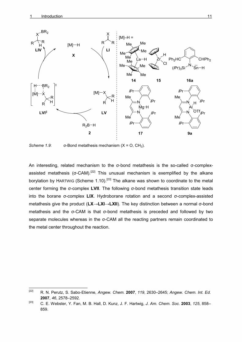
sequences often react via the σ-bond metathesis mechanism (Scheme 1.9).[21] The
fundamental step includes the insertion of the unsaturated substrate to the metal hydride X
to give the intermediate LV. The following concerted σ-bond metathesis (LVI‡) between M–O
and B–H bonds yields the hydroborated substrate LIV concomitantly with the metal hydride
X.
[21]
For La–H, see: a) K. N. Harrison, T. J. Marks, J. Am. Chem. Soc. 1992, 114, 9220–9221; for
Zr–H, see: b) S. Pereira, M. Srebnik, Organometallics 1995, 14, 3127–3128; for Ti, see c) X.
He, J. F. Hartwig, J. Am. Chem. Soc. 1996, 118, 1696–1702; d) for Mg–H, see: M. Arrowsmith,
T. J. Hadlington, M. S. Hill, G. Kociok-Köhn, Chem. Commun. 2012, 48, 4567–4569; for Sn–H
and Ge–H, see: e) T. J. Hadlington, M. Hermann, G. Frenking, C. Jones, J. Am. Chem. Soc.
2014, 136, 3028–3031; for a review of σ-bond metathesis, see: f) R. Waterman,
Organometallics 2013, 32, 7249–7263.
1 Introduction 11
Scheme 1.9: σ-Bond metathesis mechanism (X = O, CH2).
An interesting, related mechanism to the σ-bond metathesis is the so-called σ-complex-
assisted metathesis (σ-CAM).[22] This unusual mechanism is exemplified by the alkane
borylation by HARTWIG (Scheme 1.10).[23] The alkane was shown to coordinate to the metal
center forming the σ-complex LVII. The following σ-bond metathesis transition state leads
into the borane σ-complex LIX. Hydroborane rotation and a second σ-complex-assisted
metathesis give the product (LX→LXI→LXII). The key distinction between a normal σ-bond
metathesis and the σ-CAM is that σ-bond metathesis is preceded and followed by two
separate molecules whereas in the σ-CAM all the reacting partners remain coordinated to
the metal center throughout the reaction.
[22]
R. N. Perutz, S. Sabo-Etienne, Angew. Chem. 2007, 119, 2630–2645; Angew. Chem. Int. Ed.
2007, 46, 2578–2592. [23]
C. E. Webster, Y. Fan, M. B. Hall, D. Kunz, J. F. Hartwig, J. Am. Chem. Soc. 2003, 125, 858–
859.

12 THEORETICAL PART I
Scheme 1.10: σ-Complex-assisted metathesis mechanism (M = Fe, W).
Hydroboration of esters LXIII catalyzed by magnesium complex LXIV was investigated by
the group of SADOW (Scheme 1.11).[24] Detailed kinectic analysis revealed that the reaction
was zero order in the hydroborane and half order in the ester excluding the expected σ-bond
metathesis mechanism. Additionally, stoichiometric experiments indicated reversible
TISHCHENKO-type cleavage of the ester LXIII into two equivalents of aldehyde LXVI. To
explain the unexpected rate law, the authors proposed that the released aldehyde LXVI
inserts to the Mg–H bond of LXVII to give the intermediate LXVIII. Product LXV dissociation
regenerates the magnesium alkoxide. The alternative product formation directly from the
intermediate LXVII via the magnesium hydride 18 would not agree with the zero order on
[R2B–H].
[24]
D. Mukherjee, A. Ellern, A. D. Sadow, Chem. Sci. 2014, 5, 959–964.

1 Introduction 13
Scheme 1.11: Magnesium-catalyzed hydroboration of esters.
1.1.2 Outer-Sphere Mechanisms
High-valent metal oxo-complexes have been shown to be able to activate hydroboranes via
an unusual [2σ+2π] addition across the [M]=O bonds (Scheme 1.12).[25] Activation of
hydroborane 2 by the molybdenum complex LXIX gives the intermediate LXX. The
molybdenum hydride LXX reductively eliminates the borinic acid 19 and coordinates the
sulfoxide LXXI. Deoxygenation of the sulfoxide produces the sulfide LXXIII and regenerates
the molybdenum oxo-complex LXIX.
[25]
a) A. C. Fernandes, C. C. Romão, Tetrahedron Lett. 2007, 48, 9176–9179; b) A. C.
Fernandes, J. A. Fernandes, F. A. Almeida Paz, C. C. Romão, Dalton Trans. 2008, 6686–
6688; c) S. C. A. Sousa, I. C. Cabrita, A. C. Fernandes, Chem. Soc. Rev. 2012, 41, 5641–
5653.

14 THEORETICAL PART I
Scheme 1.12: Molybdenum oxo-complex-catalyzed deoxygenation of sulfoxides with
hydroboranes.
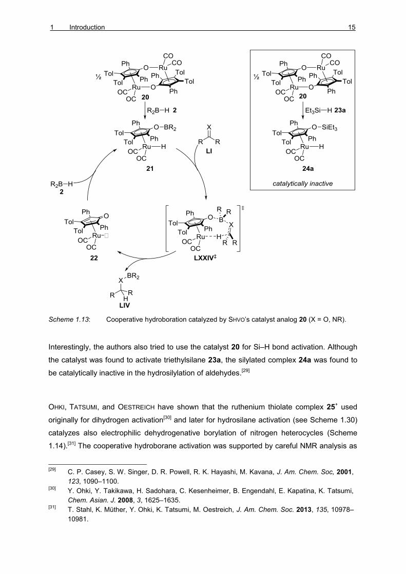
Despite the success in dihydrogen activation, the cooperative activation of E–H bonds has
not attracted attention until recently.[26] SHVO’s catalyst is one of the most successful
catalysts in cooperative hydrogenation.[27] This complex was not utilized in E–H bond
activation until 2009 when CLARK and coworkers were able to show that the complex 20 was
able to catalyze hydroboration of aldehydes, imines, and ketones (Scheme 1.13).[28] The
mechanism of the reaction was suggested to be analogous to the corresponding
hydrogenation mechanism. The cooperative hydroborane activation gives the complex 21.
Concerted hydroboration (LXXIV‡) releases the product LIV and gives the unsaturated
complex 22. Activation of B–H bond regenerates the active catalyst 21.
[26]
For recent reviews, see: a) J. R. Knusnutdinova, D. Milstein, Angew. Chem. 2015, 127,
12406–12445; Angew. Chem. Int. Ed. 2015, 54, 12236–12273; b) M. Trincado, H.
Grützmacher in Cooperative Catalysis (Ed.: R. Peters), Wiley-VCH, Weinheim, 2015, p. 67–
110. [27]
B. L. Conley, M. K. Pennington-Boggio, E. Boz, T. J. Williams, Chem. Rev. 2010, 110, 2294–
2312. [28]
L. Koren-Selfridge, H. N. Londino, J. K. Vellucci, B. J. Simmons, C. P. Casey, T. B. Clark,
Organometallics 2009, 28, 2085–2090.
1 Introduction 15
Scheme 1.13: Cooperative hydroboration catalyzed by SHVO’s catalyst analog 20 (X = O, NR).
Interestingly, the authors also tried to use the catalyst 20 for Si–H bond activation. Although
the catalyst was found to activate triethylsilane 23a, the silylated complex 24a was found to
be catalytically inactive in the hydrosilylation of aldehydes.[29]
OHKI, TATSUMI, and OESTREICH have shown that the ruthenium thiolate complex 25+ used
originally for dihydrogen activation[30] and later for hydrosilane activation (see Scheme 1.30)
catalyzes also electrophilic dehydrogenative borylation of nitrogen heterocycles (Scheme
1.14).[31] The cooperative hydroborane activation was supported by careful NMR analysis as
[29]
C. P. Casey, S. W. Singer, D. R. Powell, R. K. Hayashi, M. Kavana, J. Am. Chem. Soc, 2001,
123, 1090–1100. [30]
Y. Ohki, Y. Takikawa, H. Sadohara, C. Kesenheimer, B. Engendahl, E. Kapatina, K. Tatsumi,
Chem. Asian. J. 2008, 3, 1625–1635. [31]
T. Stahl, K. Müther, Y. Ohki, K. Tatsumi, M. Oestreich, J. Am. Chem. Soc. 2013, 135, 10978–
10981.

16 THEORETICAL PART I
well as X-ray crystal structure of 26+. The activated boryl group of 26+ is attacked by the
nucleophilic indole C-3 carbon. The resulting WHELAND intermediate LXXVI+ is deprotonated
by the ruthenium hydride 27 to furnish the borylated indole LXXVII and the dihydrogen
adduct 28+. Release of dihydrogen regenerates the active ruthenium catalyst 25+.
Scheme 1.14: Ruthenium thiolate 25+-catalyzed borylation of indoles (counteranion
BArF
4– omitted for clarity).
The anionic NNN ruthenium pincer complex 29 was utilized in nitrile hydroboration (Scheme
1.15).[32] The mechanism proposed by SZYMCZAK is initiated by borylation of the precatalyst
29 to the complex 30. The borinic esters were proposed to form LEWIS pairs with the nitrile
LXXVIII. Outer-sphere hydride and boryl transfer gives the intermediate LXXX with the imine
still coordinated to the boron. A second hydroboration produces the bisborylated amine
LXXXI and the active catalyst 30. Interestingly, it is not clear if the ruthenium center is
actively involved in the catalytic cycle after the initial hydroboration (29→30). Through the
rest of the catalytic cycle the substrate is being activated by the LEWIS-acidic boron atom and
[32]
J. B. Geri, N. K. Szymczak, J. Am. Chem. Soc. 2015, 137, 12808–12814.

1 Introduction 17
the experimental evidence could not reveal whether the subsequent hydroborations occur
stepwise, assisted by the ruthenium, or via concerted additions of hydroboranes.[33]
Scheme 1.15: Cooperative hydroborane activation proposed by SZYMCZAK (P = Ph3P).
[33]
The mechanism where the ruthenium center remains a bystander during the active catalytic
cycle, could be defined as a peripheral mechanism (vide infra).

18 THEORETICAL PART I
1.2 Mechanisms of Metal-Catalyzed Generation of Group 14
Electrophiles
Hydrosilanes are usually relatively inert air- and moisture-stable liquids. Nevertheless, the
Si–H bond is readily activated to give formally a hydride and a silicon cation.[34] The ease of
handling, relatively low toxicity, and high reactivity in metal-catalyzed reactions has made
hydrosilanes attractive reagents, not just as hydrogen surrogates in reduction chemistry but
also in the synthesis of various organosilicon compounds. The continuous demand for
efficient hydrosilylation processes has spurred numerous mechanistic investigations of these
transformations. The chemistry of hydrogermanes remains less developed but according to
the known examples, their reactivities and mechanisms are often comparable to their silicon
counterparts.[35] Unlike with most hydrosilanes and hydrogermanes,[36] the Sn–H bond of
hydrostannanes are readily cleaved homolytically to form tin-centered radicals.[37] The high
toxicity of hydrostannanes and the tendency to react via radical pathways have abated the
wide use of tin electrophiles.
1.2.1 Inner-Sphere Mechanisms
Early mechanistic investigations of metal-catalyzed hydrosilylation reactions focused on the
industrially important hydrosilylation of alkenes. The first detailed mechanism involving Si–H
bond activation was reported in 1965 by CHALK and HARROD (Scheme 1.16).[38] The authors
investigated platinum-catalyzed hydrosilylation of alkenes and proposed a mechanism where
the hydrosilane 23 first oxidatively adds to the metal center II to give silyl hydride complex
LXXXII. Migratory insertion of the alkene LXXXIII to the metal hydride gives silyl alkyl
complex LXXXV which releases the desired product LXXXVI via reductive elimination.
[34]
a) The Chemistry of Organic Silicon Compounds, Vol. 3 (Eds.: Z. Rappoport, Y. Apeloig),
Wiley, Chichester, 2001; b) The Chemistry of Organic Silicon Compounds, Vol. 2 (Eds.: Z.
Rappoport, Y. Apeloig), Wiley, Chichester, 1998; c) The Chemistry of Organic Silicon
Compounds (Eds.: S. Patai, Z. Rappoport), Wiley, Chichester, 1989. [35]
The chemistry of organic germanium, tin and lead compounds, Vol. 1 (Ed.: S. Patai), Wiley,
Chichester, 1995. [36]
C. Chatgilialoglu, Chem. Rev. 1995, 95, 1229–1251 [37]
N. D. Smith, J. Mancuso, M. Lautens, Chem. Rev. 2000, 100, 3257–3282. [38]
A. J. Chalk, J. F. Harrod, J. Am. Chem. Soc. 1965, 87, 16–21.

1 Introduction 19
Scheme 1.16: CHALK–HARROD mechanism of the hydrosilylation of alkenes.
CHALK–HARROD-type mechanisms have also been proposed in the palladium-catalyzed
hydrogermylation of alkynes[39] and copper-catalyzed hydrostannylation of alkynones.[40]
Later, a so-called modified CHALK–HARROD mechanism was proposed where the order of
events is changed such that the Si–C bond is formed first (Scheme 1.17,
LXXXVIII→LXXXIX).[41] The following reductive elimination of the alkyl hydride releases the
product XC.[42] The same initial intermediate LXXXIX can lead to two other distinct products
as well.[43,44] In the dehydrogenative mechanism, a β-hydride elimination takes place giving
[39]
H. Konoshita, T. Nakamura, H. Kakiya, H. Shinokubo, S. Matsubara, K. Oshima, Org. Lett.
2001, 3, 2521–2524. [40]
L. T. Leung, S. K. Leung, P. Chiu, Org. Lett. 2005, 7, 5249–5252. [41]
a) M. A. Schroeder, M. S. Wrighton, J. Organomet. Chem. 1977, 128, 345–358; b) C. L.
Reichel, M. S. Wrighton, Inorg. Chem. 1980, 19, 3858–3860; c) C. L. Randolph, M. S.
Wrighton, J. Am. Chem. Soc. 1986, 108, 3366–3374. [42]
For comparative computational analysis of CHALK–HARROD and the modified CHALK–HARROD
mechanisms, see: a) S. Sakaki, N. Mizoe, M. Sugimoto, Organometallics 1998, 17, 2510–
2523; b) G. Giorgi, F. De Angelis, N. Re, A. Sgamellotti, Fut. Gen. Comp. Syst. 2004, 20, 781–
791. [43]
For early examples of dehydrogenative silylation of alkenes, see: a) A. Millan, E. Towns, P. M.
Maitlis, J. Chem. Soc., Chem. Commun. 1981, 673–674; b) F. Seitz, M. S. Wrighton, Angew.

20 THEORETICAL PART I
vinylic or allylic silanes (XCI or XCII, respectively) and dihydrogen complex XCIII. Formal
reductive elimination of dihydrogen closes the catalytic cycle.[45] Often mixtures of XC, XCI,
and XCII can be seen, indicating that several mechanistic pathways are operating at the
same time.
Scheme 1.17: Modified CHALK–HARROD mechanism including the formation of vinylic and allylic
silanes via dehydrogenation.
The palladium-catalyzed hydrostannylation and hydrogermylation reactions investigated by
OSHIMA were also proposed to proceed via the modified CHALK–HARROD-type mechanism.[46]
A related mechanism has been proposed by GEVORGYAN in the hydrosilylation, -germylation,
-stannylation as well as distannylation and silastannylation of reactive cyclopropenes XCIV
Chem. 1988, 100, 281–283; Angew. Chem. Int. Ed. Engl. 1988, 27, 289–291; c) M. R. Kesti,
R. M. Waymouth, Organometallics 1992, 11, 1095–1103, for recent examples of selective
synthesis of vinylic or allylic silanes, see: d) J. R. McAtee, S. E. S. Martin, D. T. Ahneman, K.
A. Johnson, D. A. Watson, Angew. Chem. 2012, 124, 3723–3727; Angew. Chem. Int. Ed.
2012, 51, 3663–3667 (vinylic silanes using R3Si–I); e) J. R. McAtee, G. P. A. Yap, D. A.
Watson, J. Am. Chem. Soc. 2014, 136, 10166–10172 (allylic silanes using R3Si–I); f) C. C. H.
Atienza, T. Diao, K. J. Weller, S. A. Nye, K. M. Lewis, J. G. P. Delis, J. L. Boyer, A. K. Roy, P.
J. Chirik, J. Am. Chem. Soc. 2014, 136, 12108–12118 (allylic silanes using R3Si–H). [44]
For dehydrogenative germylation, see: N. Furukawa, N. Kourogi, Y. Seki, Organometallics
1999, 18, 3764–3767. Although no mechanism was provided, the reaction is likely to proceed
via a similar mechanism as shown here for the dehydrogenative silylation. [45]
Often a sacrificial dihydrogen acceptor is required for efficient turnover. [46]
Y. Ichinose, H. Oda, K. Oshima, K. Utimoto, Bull. Chem. Soc. Jpn. 1987, 60, 3468–3470.

1 Introduction 21
(Scheme 1.18).[47] Exclusive syn-addition was observed in all cases and the insertion takes
place at the sterically less hindered face via intermediate XCVI.
Scheme 1.18: Palladium-catalyzed functionalization of cyclopropenes.
The hydrosilylation of alkynes typically proceeds via CHALK–HARROD or modified CHALK–
HARROD-type mechanisms leading to exclusive syn-silylation (Scheme 1.19, XCIX→C).[48]
Unusual trans-hydrosilylation was first reported in 1981 by NILE.[49] The rhodium-catalyzed
formation of the (E)-vinylsilanes CIV was explained by isomerization via a carbene
intermediate CI (Scheme 1.19). TANKE and CRABTREE reported a similar reactivity using
iridium catalysts.[50] The authors did not find the carbene CI as a feasible intermediate but
proposed the reversible formation of the metallacyclopropene CII instead as the
isomerization pathway.
TROST investigated the hydrosilylation of alkynes and found that ruthenium complexes 32+
and 33+ gave unusual MARKOVNIKOV products.[51] In addition, control reactions with
deuterium-labeled hydrosilanes showed that the hydrosilylation occurs in an anti-fashion. To
explain the observed selectivity, TROST and WU also proposed carbene CI or
[47]
A. Trofimov, M. Rubina, M. Rubin, V. Gevorgyan, J. Org. Chem. 2007, 72, 8910–8920. [48]
B. Marciniec in Hydrosilylation. A Comprehensive Review on Recent Advances (Ed. B.
Marciniec), Springer, Netherlands, 2009, p. 53–86. [49]
K. A. Brady, T. A. Nile, J. Organomet. Chem. 1981, 206, 299–304. [50]
R. S. Tanke, R. H. Crabtree, J. Am. Chem. Soc. 1990, 112, 7984–7989. [51]
a) B. M. Trost, Z. T. Ball, J. Am. Chem. Soc. 2001, 123, 12726–12727; b) B. M. Trost, Z. T.
Ball, J. Am. Chem. Soc. 2002, 125, 30–31.

22 THEORETICAL PART I
ruthenacyclopropene CII as the intermediate leading to the isomerization of the alkene
intermediate.[52]
Scheme 1.19: Mechanism of trans-selective hydrosilylation of alkynes.
In 2013, WU demonstrated that silyl-substituted alkynes could be hydrosilylated through an
anti-MARKOVNIKOV syn-addition with the complex 32+ or through MARKOVNIKOV anti-addition
with the complex 33+ (Scheme 1.20).[53] The switch in the selectivity was explained by the
relative stability of the intermediates during the isomerization through the intermediate CII.
[52]
L. W. Chung, Y.-D. Wu, B. M. Trost, Z. T. Ball, J. Am. Chem. Soc. 2003, 125, 11578–11582. [53]
S. Ding, L.-J. Song, L. W. Chung, X. Zhang, J. Sun, Y.-D. Wu, J. Am. Chem. Soc. 2013, 135,
13835–13842.

1 Introduction 23
Scheme 1.20: Regio- and stereodivergent hydrosilylation of alkynes by WU.
The C-sp2 silylation of styrene 35 developed by MARCINIEC allows the functionalization with
vinylsilanes 38 (Scheme 1.21).[54] The proposed mechanism begins with oxidative addition of
the alkene C–H bond to the metal center forming the intermediate 37. Following vinylsilane
coordination (39), and insertion to the metal hydride gives the complex 40. The β-silyl
elimination releases ethylene to form the silyl complex 41. Finally, a reductive elimination
releases the (E)-β-silyl styrene 42.
Scheme 1.21: Rhodium-catalyzed silylation of alkenes (COD = 1,5-cyclooctadiene).
[54]
B. Marciniec, E. Walczuk-Guściora, C. Pietraszuk, Organometallics 2001, 20, 3423–3428.

24 THEORETICAL PART I
The hydrosilylation mechanism of carbonyl groups was first studied by OJIMA. The authors
proposed that the mechanism would be similar to the modified CHALK–HARROD mechanism
(Scheme 1.22, II→LXXXII). Coordination of the oxygen atom to the metal center (CIX)
followed by silyl transfer gives intermediate CX which releases the silyl ether CXI via
reductive elimination.[55]
Scheme 1.22: Mechanism of carbonyl hydrosilylation proposed by OJIMA.
The rhodium-catalyzed hydrosilylation of α,β-unsaturated carbonyl compounds was
investigated by CHAN (Scheme 1.23).[56] Monohydrosilanes 23 were found to give selective
1,4-reduction while di- and trihydrosilanes 23’/23’’ gave 1,2-reduction. The observed change
in selectivity could not be explained with the OJIMA mechanisms, hence an alternative
mechanism was proposed. After the initial oxidative addition of the hydrosilane (II→LXXXII’),
the oxygen atom of the carbonyl group coordinates to the silicon atom and not to the
rhodium center of the complex to give CXII. In the case of monohydrosilane the rhodium
center then undergoes allylic transposition to give intermediate CXIII. Reductive elimination
[55]
a) I. Ojima, M. Nihonyanagi, T. Kogure, M. Kumagai, S. Horiuchi, K. Nakatsugawa, Y. Nagai,
J. Organomet. Chem. 1975, 94, 449–461; b) I. Ojima, T. Kogure, M. Kumagai, S. Horiuchi, T.
Sato, J. Organomet. Chem. 1976, 122, 83–97. [56]
G. Z. Zheng, T. H. Chan, Organometallics 1995, 14, 70–79.

1 Introduction 25
releases the silyl enol ether 44 and regenerates the catalyst II. With di- or trihydrosilanes
23’/23’’ the intermediate CXII can lead to hydride transfer from the silyl group to the carbon
center of the carbonyl (CXIV). The reductive elimination of the hydrosilane releases the
1,2-reduced silyl ether 45 and the catalyst II.[57]
Scheme 1.23: Mechanism of 1,2- and 1,4-hydrosilylation of α,β-unsaturated carbonyl compounds.
The ability of di- and trihydrosilanes 23’/23’’ to form silylene complexes with transition metal
centers gives access to highly reactive complexes. In 2003, TILLEY and GLASER reported the
ruthenium silylene complex-catalyzed hydrosilylation of alkenes (Scheme 1.24).[58] Based on
the exclusive anti-MARKOVNIKOV selectivity, a new mechanism was proposed. The silylene
hydride group 47+ is proposed to directly add to the alkene XXII in a concerted [2σ+2π]-
cycloaddition to give CXV+. Hydride migration from the ruthenium to the silicon atom followed
by reductive elimination releases the product CVII and the ruthenium catalyst 46+.
[57]
The mechanism with di- and trihydrosilanes could in fact be considered as an outer-sphere
mechanism. [58]
a) P. B. Glaser, T. D. Tilley, J. Am. Chem. Soc. 2003, 125, 13640–13641; b) M. A. Rankin, D.
F. MacLean, G. Schatte, R. McDonald, M. Stradiotto, J. Am. Chem. Soc. 2007, 129, 15855–
15864.

26 THEORETICAL PART I
Scheme 1.24: Hydrosilylation of alkenes via a silylene complex 47+ (counteranion B(C6F5)4
–
omitted for clarity).
A similar silylene mechanism was adapted by HOFMANN, GADE, and co-workers in the
rhodium-catalyzed hydrosilylation of ketones.[59]
As with hydroborations the majority of the hydrosilylation reactions catalyzed by early
transition metals operate by a σ-bond metathesis mechanism. Typically in these
mechanisms a metal hydride reduces the carbonyl to form a metal alkoxide. Following
σ-bond metathesis between the M–O and Si–H bonds releases the product and regenerates
the metal hydride analogous to the σ-bond metathesis mechanism with hydroboranes
(Scheme 1.9).[60]
The σ-bond metathesis mechanism has been widely studied and generally accepted for
many early transition metals. However, some of these reactions have been questioned. The
copper hydride-catalyzed hydrosilylation of carbonyls was assumed to proceed via a σ-bond
[59]
N. Schneider, M. Finger, C. Haferkemper, S. Bellemin-Laponnaz, P. Hofmann, L. H. Gade,
Angew. Chem. 2009, 121, 1637–1641; Angew. Chem. Int. Ed. 2009, 48, 1609–1613. [60]
S. Rendler, M. Oestreich in Modern Reduction Methods (Eds.: P. G. Andersson, I. J.
Munslow), Wiley-VCH, Weinheim, 2008, p. 183–207.
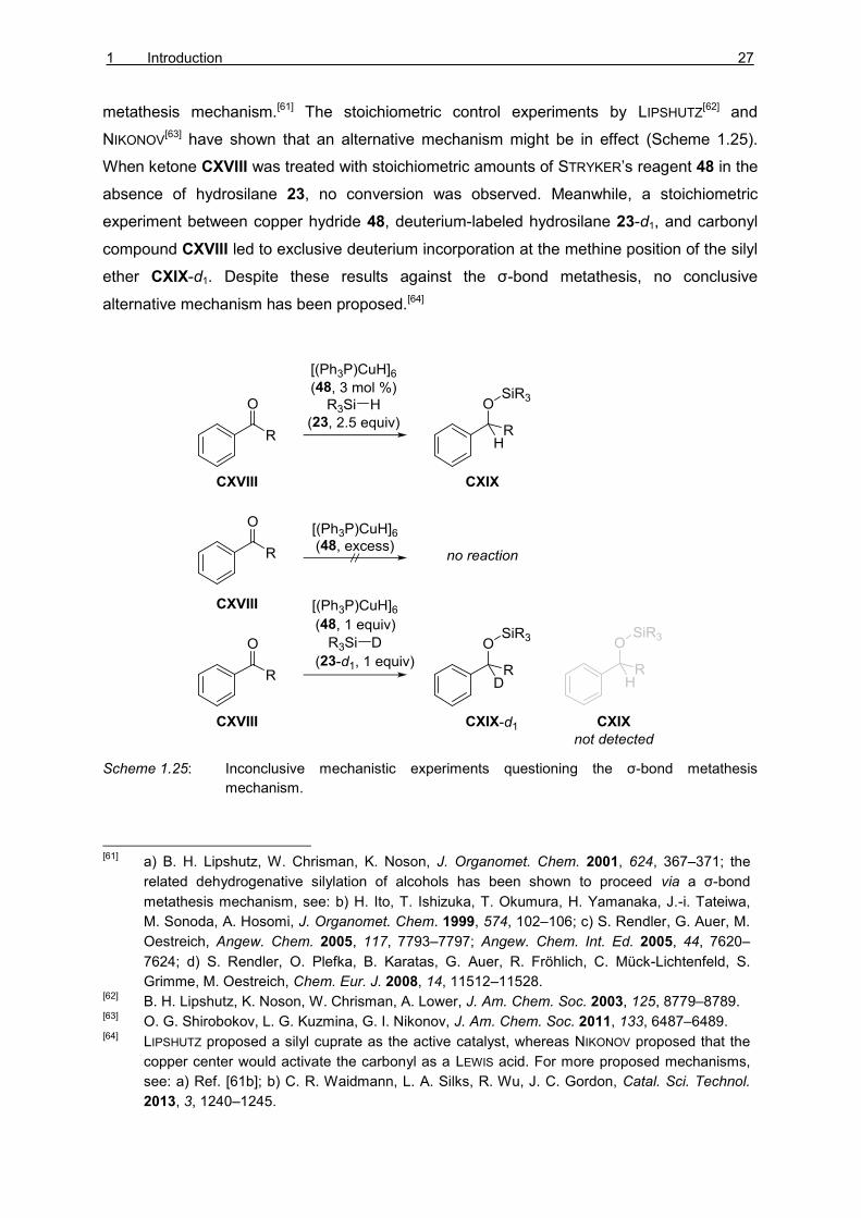
1 Introduction 27
metathesis mechanism.[61] The stoichiometric control experiments by LIPSHUTZ[62] and
NIKONOV[63] have shown that an alternative mechanism might be in effect (Scheme 1.25).
When ketone CXVIII was treated with stoichiometric amounts of STRYKER’s reagent 48 in the
absence of hydrosilane 23, no conversion was observed. Meanwhile, a stoichiometric
experiment between copper hydride 48, deuterium-labeled hydrosilane 23-d1, and carbonyl
compound CXVIII led to exclusive deuterium incorporation at the methine position of the silyl
ether CXIX-d1. Despite these results against the σ-bond metathesis, no conclusive
alternative mechanism has been proposed.[64]
Scheme 1.25: Inconclusive mechanistic experiments questioning the σ-bond metathesis
mechanism.
[61]
a) B. H. Lipshutz, W. Chrisman, K. Noson, J. Organomet. Chem. 2001, 624, 367–371; the
related dehydrogenative silylation of alcohols has been shown to proceed via a σ-bond
metathesis mechanism, see: b) H. Ito, T. Ishizuka, T. Okumura, H. Yamanaka, J.-i. Tateiwa,
M. Sonoda, A. Hosomi, J. Organomet. Chem. 1999, 574, 102–106; c) S. Rendler, G. Auer, M.
Oestreich, Angew. Chem. 2005, 117, 7793–7797; Angew. Chem. Int. Ed. 2005, 44, 7620–
7624; d) S. Rendler, O. Plefka, B. Karatas, G. Auer, R. Fröhlich, C. Mück-Lichtenfeld, S.
Grimme, M. Oestreich, Chem. Eur. J. 2008, 14, 11512–11528. [62]
B. H. Lipshutz, K. Noson, W. Chrisman, A. Lower, J. Am. Chem. Soc. 2003, 125, 8779–8789. [63]
O. G. Shirobokov, L. G. Kuzmina, G. I. Nikonov, J. Am. Chem. Soc. 2011, 133, 6487–6489. [64]
LIPSHUTZ proposed a silyl cuprate as the active catalyst, whereas NIKONOV proposed that the
copper center would activate the carbonyl as a LEWIS acid. For more proposed mechanisms,
see: a) Ref. [61b]; b) C. R. Waidmann, L. A. Silks, R. Wu, J. C. Gordon, Catal. Sci. Technol.
2013, 3, 1240–1245.

28 THEORETICAL PART I
The calcium hydride 49-catalyzed hydrosilylation was proposed to proceed via the formation
of a hypervalent silyl hydride 50 (Scheme 1.26).[65] The addition of the extra hydride to the
silicon center increases the LEWIS acidity of the silicon.[66] The concerted hydride transfer via
six-coordinated silicon intermediate CXX gives the silyl ether CXXI. The product CXXII is
released after hydride transfer to a second trihydrosilane 23’’a.
Scheme 1.26: Proposed mechanism of calcium hydride-catalyzed hydrosilylation of ketones.
As with hydroboranes, σ-complex-assisted metathesis-type reaction have been proposed for
hydrosilanes as well (see Scheme 1.10). Likewise, these processes have only been
observed in silico and direct experimental evidence has not been obtained yet.[22,67]
[65]
J. Spielmann, S. Harder, Eur. J. Inorg. Chem. 2008, 1480–1486. [66]
a) S. E. Denmark, G. L. Beutner, Angew. Chem. 2008, 120, 1584–1663; Angew. Chem. Int.
Ed. 2008, 47, 1560–1638; b) S. Rendler, M. Oestreich, Synthesis 2005, 1727–1747; c) M.
Kira, L. C. Zhang in Chemistry of Hypervalent Compounds (Ed.: K.-y. Akiba), Wiley-VCH, New
York, 1999, p. 147–169; d) C. Chuit, R. J. P. Corriu, C. Reye, J. C. Young, Chem. Rev. 1993,
93, 1371–1448. [67]
For Ge–H bond activation involving proposed σ-CAM mechanism, see: M. Murai, K.
Matsumoto, R. Okada, K. Takai, Org. Lett. 2014, 16, 6492–6495.

1 Introduction 29
1.2.2. Outer-Sphere Mechanisms
1.2.2.1 Cooperative Activation Mechanisms
The cooperative activation of hydrosilanes was first utilized in catalysis by TOSTE and co-
workers in 2003 (Scheme 1.27).[68] The rhenium(V) dioxo-complex 51 was proposed to
activate hydrosilanes 23 by [2σ+2π]-addition of the Si–H and Re=O bonds to give 52.
Following insertion of the carbonyl group into the metal hydride (LXVI→CXXIV) and
subsequent silyl transfer produces the silyl ether CXVI and regenerates the catalyst 51.
Scheme 1.27: Proposed mechanism of aldehyde hydrosilylation catalyzed by rhenium complex
51.
The ruthenium-catalyzed hydrosilylation of carbon dioxide into silyl formate by DEGLMANN,
HOFMANN, and PITTER was proposed to involve an interesting activation mode (Scheme
[68]
a) J. J. Kennedy-Smith, K. A. Nolin, H. P. Gunterman, F. D. Toste, J. Am. Chem. Soc. 2003,
125, 4056–4057; b) K. A. Nolin, J. R. Krumper, M. D. Pluth, R. G. Bergman, F. D. Toste, J.
Am. Chem. Soc. 2007, 129, 14684–14696.
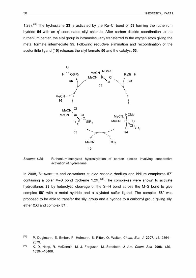
30 THEORETICAL PART I
1.28).[69] The hydrosilane 23 is activated by the Ru–Cl bond of 53 forming the ruthenium
hydride 54 with an η1-coordinated silyl chloride. After carbon dioxide coordination to the
ruthenium center, the silyl group is intramolecularly transferred to the oxygen atom giving the
metal formate intermediate 55. Following reductive elimination and recoordination of the
acetonitrile ligand (10) releases the silyl formate 56 and the catalyst 53.
Scheme 1.28: Ruthenium-catalyzed hydrosilylation of carbon dioxide involving cooperative
activation of hydrosilane.
In 2008, STRADIOTTO and co-workers studied cationic rhodium and iridium complexes 57+
containing a polar M–S bond (Scheme 1.29).[70] The complexes were shown to activate
hydrosilanes 23 by heterolytic cleavage of the Si–H bond across the M–S bond to give
complex 58+ with a metal hydride and a silylated sulfur ligand. The complex 58+ was
proposed to be able to transfer the silyl group and a hydride to a carbonyl group giving silyl
ether CXI and complex 57+.
[69]
P. Deglmann, E. Ember, P. Hofmann, S. Pitter, O. Walter, Chem. Eur. J. 2007, 13, 2864–
2879. [70]
K. D. Hesp, R. McDonald, M. J. Ferguson, M. Stradiotto, J. Am. Chem. Soc. 2008, 130,
16394–16406.

1 Introduction 31
Scheme 1.29: Cooperative activation of Si–H bonds by rhodium thiolate complex 57+ in carbonyl
hydrosilylation (counteranion B(C6F5)4– omitted for clarity).
In addition to the dehydrogenative borylation of indoles (see Scheme 1.14), the ruthenium
thiolate complex 25+ was utilized by OESTREICH in catalytic Si–H bond activation (Scheme
1.30). The activation mode of complex 59+ was investigated in detail by stoichiometric
experiments, NMR spectroscopy, DFT calculations, and by X-ray crystallography. The
combined results provided conclusive evidence for the cooperative activation mode.[71] The
activated silyl group 59+ is then attacked by the LEWIS-basic substrate to give the ruthenium
hydride 27 and the corresponding silylated intermediate CXXVII+. Depending on the nature
of the substrate, the ruthenium hydride complex 27 was shown to be able to act as a hydride
source giving reductive hydrosilylation products (60+→61, shown for pyridine 1,4-
reduction)[72] or as a base leading to dehydrogenative silylation (CXXVIII+→CXXIX, shown for
dehydrogenative ketone silylation).[73]
[71]
T. Stahl, P. Hrobárik, C. D. F. Königs, Y. Ohki, K. Tatsumi, S. Kemper, M. Kaupp, H. F. T.
Klare, M. Oestreich, Chem. Sci. 2015, 6, 4324–4334. [72]
a) T. Stahl, H. F. T. Klare, M. Oestreich, J. Am. Chem. Soc. 2013, 135, 1248–1251; b) C. D. F.
Königs, H. F. T. Klare, M. Oestreich, Angew. Chem. 2013, 125, 10260–10263; Angew. Chem.
Int. Ed. 2013, 125, 10260–10263. [73]
a) H. F. T. Klare, M. Oestreich, J.-i. Ito, H. Nishiyama, Y. Ohki, K. Tatsumi, J. Am. Chem. Soc.
2011, 133, 3312–3315; b) C. D. F. Königs, H. F. T. Klare, Y. Ohki, K. Tatsumi, M. Oestreich,
Org. Lett. 2012, 14, 2842–2845; c) C. D. F. Königs, M. F. Müller, N. Aiguabella, H. F. T. Klare,
M. Oestreich, Chem. Commun. 2013, 49, 1506–1508; d) J. Hermeke, H. F. T. Klare, M.
Oestreich, Chem. Eur. J. 2014, 20, 9250–9254; e) L. Omann, M. Oestreich, Angew. Chem.

32 THEORETICAL PART I
Scheme 1.30: Dehydrogenative silylation (LB = methyl ketone) and reductive hydrosilylation (LB
= pyridine) catalyzed by the ruthenium thiolate 25+ (counteranion BAr
F4– omitted for
clarity).
The iridium NSiN pincer complex 62 was used by FERNÁNDEZ-ALVAREZ and ORO to
hydrosilylate carbon dioxide into silyl formate 56 (Scheme 1.31).[74] The mechanistic proposal
based on DFT calculations suggested that the hydrosilane 23 would be cooperatively
2015, 127, 10414–10418; Angew. Chem. Int. Ed. 2015, 54, 10276–10279; f) S. Wübbolt, M.
Oestreich, Angew. Chem. 2015, 127, 16103–16106; Angew. Chem. Int. Ed. 2015, 54, 15876–
15879. [74]
R. Lalrempuia, M. Iglesias, V. Polo, P. J. Sanz Miguel, F. J. Fernández-Alvarez, J. J. Pérez-
Torrente, L. A. Oro, Angew. Chem. 2012, 124, 12996–12999; Angew. Chem. Int. Ed. 2012, 51,
12824–12827.
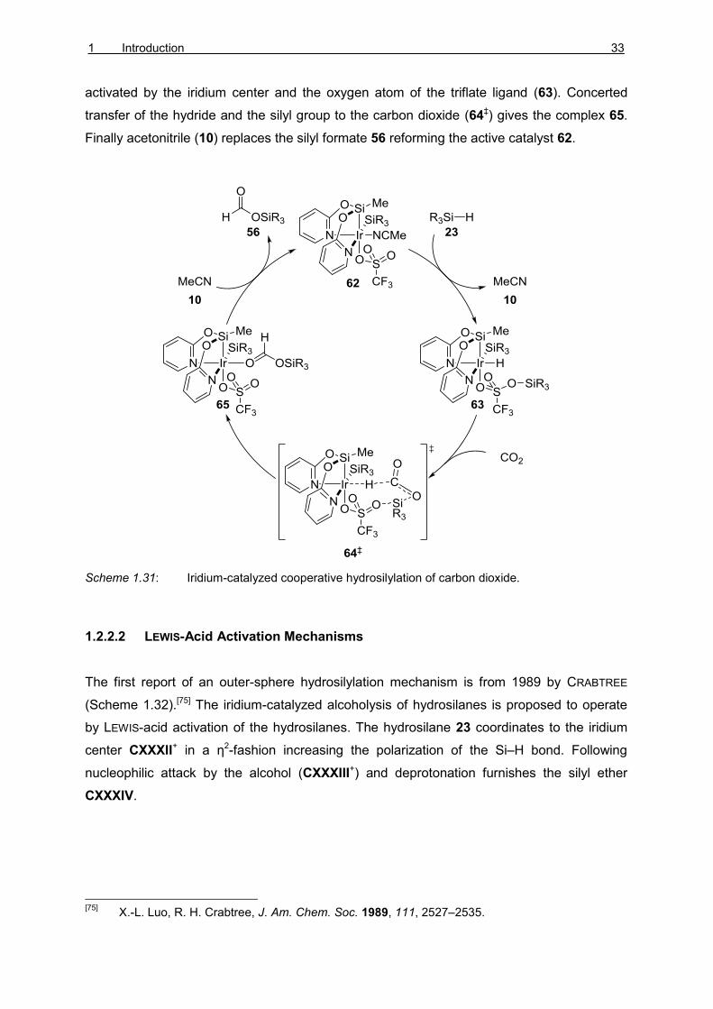
1 Introduction 33
activated by the iridium center and the oxygen atom of the triflate ligand (63). Concerted
transfer of the hydride and the silyl group to the carbon dioxide (64‡) gives the complex 65.
Finally acetonitrile (10) replaces the silyl formate 56 reforming the active catalyst 62.
Scheme 1.31: Iridium-catalyzed cooperative hydrosilylation of carbon dioxide.
1.2.2.2 LEWIS-Acid Activation Mechanisms
The first report of an outer-sphere hydrosilylation mechanism is from 1989 by CRABTREE
(Scheme 1.32).[75] The iridium-catalyzed alcoholysis of hydrosilanes is proposed to operate
by LEWIS-acid activation of the hydrosilanes. The hydrosilane 23 coordinates to the iridium
center CXXXII+ in a η2-fashion increasing the polarization of the Si–H bond. Following
nucleophilic attack by the alcohol (CXXXIII+) and deprotonation furnishes the silyl ether
CXXXIV.
[75]
X.-L. Luo, R. H. Crabtree, J. Am. Chem. Soc. 1989, 111, 2527–2535.

34 THEORETICAL PART I
Scheme 1.32. Outer-sphere dehydrogenative coupling of hydrosilanes and alcohols
(counteranion SbF6– omitted for clarity).
The second seminal report came in 2000 by BULLOCK (Scheme 1.33).[76] The homogeneous
tungsten-catalyzed hydrosilylation of ketones was proposed to proceed via a similar ionic
mechanism as the related hydrogenation.[77] The electrophilic tungsten center 70+ was shown
to coordinate the hydrosilane 23 to give complex 71+. Nucleophilic attack by the carbonyl
oxygen gave the silylcarboxonium ion CXXXV+ and the neutral tungsten hydride 72. Hydride
transfer to the carbon atom of the silylcarboxonium ion CXXXV+ and coordination of
hydrosilane 23 gave the desired silyl ether CXI and the catalyst 71+.
[76]
V. K. Dioumaev, R. M. Bullock, Nature 2003, 424, 530–532. [77]
a) R. M. Bullock, M. H. Voges, J. Am. Chem. Soc. 2000, 122, 12594–12595; b) M. H. Voges,
R. M. Bullock, J. Chem. Soc., Dalton Trans. 2002, 757–770.
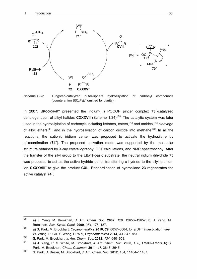
1 Introduction 35
Scheme 1.33: Tungsten-catalyzed outer-sphere hydrosilylation of carbonyl compounds
(counteranion B(C6F5)4– omitted for clarity).
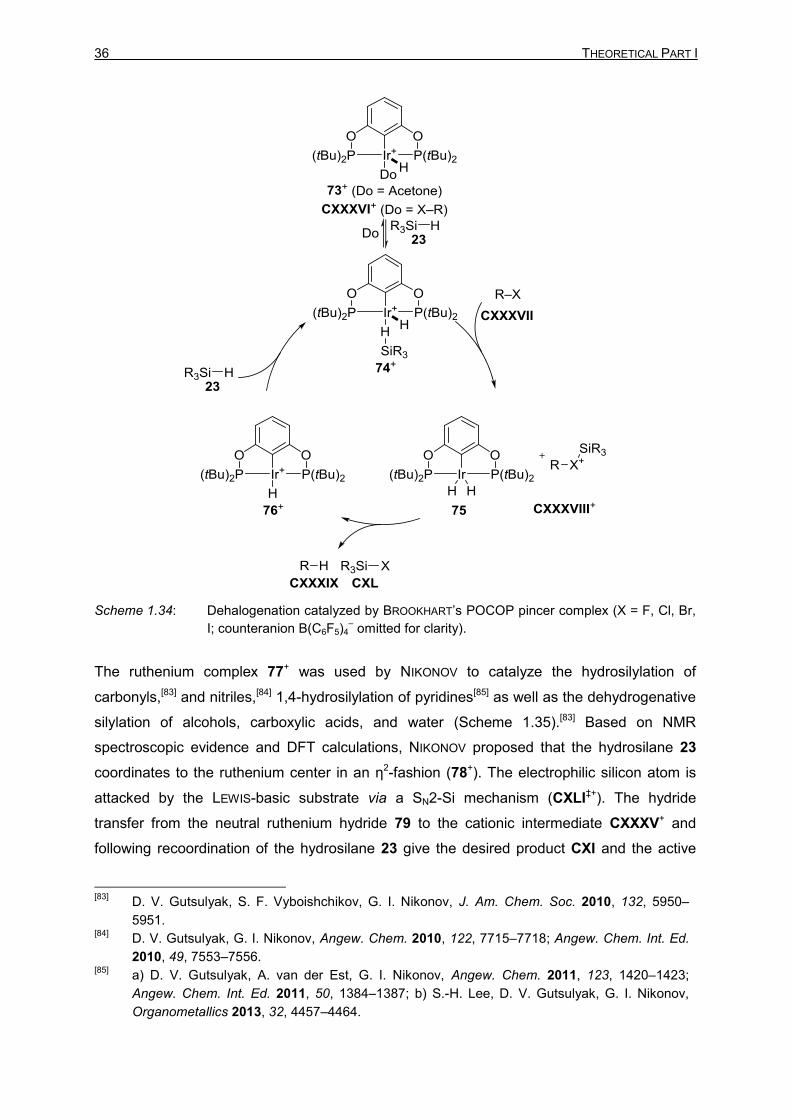
In 2007, BROOKHART presented the iridium(III) POCOP pincer complex 73+-catalyzed
dehalogenation of alkyl halides CXXXVII (Scheme 1.34).[78] The catalytic system was later
used in the hydrosilylation of carbonyls including ketones, esters,[79] and amides,[80] cleavage
of alkyl ethers,[81] and in the hydrosilylation of carbon dioxide into methane.[82] In all the
reactions, the cationic iridium center was proposed to activate the hydrosilane by
η1-coordination (74+). The proposed activation mode was supported by the molecular
structure obtained by X-ray crystallography, DFT calculations, and NMR spectroscopy. After
the transfer of the silyl group to the LEWIS-basic substrate, the neutral iridium dihydride 75
was proposed to act as the active hydride donor transferring a hydride to the silylhalonium
ion CXXXVIII+ to give the product CXL. Recoordination of hydrosilane 23 regenerates the
active catalyst 74+.
[78]
a) J. Yang, M. Brookhart, J. Am. Chem. Soc. 2007, 129, 12656–12657; b) J. Yang, M.
Brookhart, Adv. Synth. Catal. 2009, 351, 175–187. [79]
a) S. Park, M. Brookhart, Organometallics 2010, 29, 6057–6064; for a DFT investigation, see :
W. Wang, P. Gu, Y. Wang, H. Wei, Organometallics 2014, 33, 847–857. [80]
S. Park, M. Brookhart, J. Am. Chem. Soc. 2012, 134, 640–653.
[81] a) J. Yang, P. S. White, M. Brookhart, J. Am. Chem. Soc. 2008, 130, 17509–17518; b) S.
Park, M. Brookhart, Chem. Commun. 2011, 47, 3643–3645. [82]
S. Park, D. Bézier, M. Brookhart, J. Am. Chem. Soc. 2012, 134, 11404–11407.
36 THEORETICAL PART I
Scheme 1.34: Dehalogenation catalyzed by BROOKHART’s POCOP pincer complex (X = F, Cl, Br,
I; counteranion B(C6F5)4– omitted for clarity).
The ruthenium complex 77+ was used by NIKONOV to catalyze the hydrosilylation of
carbonyls,[83] and nitriles,[84] 1,4-hydrosilylation of pyridines[85] as well as the dehydrogenative
silylation of alcohols, carboxylic acids, and water (Scheme 1.35).[83] Based on NMR
spectroscopic evidence and DFT calculations, NIKONOV proposed that the hydrosilane 23
coordinates to the ruthenium center in an η2-fashion (78+). The electrophilic silicon atom is
attacked by the LEWIS-basic substrate via a SN2-Si mechanism (CXLI‡+). The hydride
transfer from the neutral ruthenium hydride 79 to the cationic intermediate CXXXV+ and
following recoordination of the hydrosilane 23 give the desired product CXI and the active
[83]
D. V. Gutsulyak, S. F. Vyboishchikov, G. I. Nikonov, J. Am. Chem. Soc. 2010, 132, 5950–
5951. [84]
D. V. Gutsulyak, G. I. Nikonov, Angew. Chem. 2010, 122, 7715–7718; Angew. Chem. Int. Ed.
2010, 49, 7553–7556. [85]
a) D. V. Gutsulyak, A. van der Est, G. I. Nikonov, Angew. Chem. 2011, 123, 1420–1423;
Angew. Chem. Int. Ed. 2011, 50, 1384–1387; b) S.-H. Lee, D. V. Gutsulyak, G. I. Nikonov,
Organometallics 2013, 32, 4457–4464.

1 Introduction 37
catalyst 78+. The proposed mechanism was later supported by DFT calculations from HOUK
and WU.[86] However, the additional calculations indicated that the energy differences
between the outer-sphere mechanism and traditional inner-sphere mechanisms are small.
Scheme 1.35: Mechanism of ketone hydrosilylation by NIKONOV (counteranion B(C6F5)4– omitted
for clarity).
Iridium-catalyzed trans-hydrosilylation of alkynes was achieved by ORO through an
unconventional mechanism (Scheme 1.36). The iridium complex 81+ was shown to
hydrosilylate alkynes in a trans-fashion, but only when acetone (83) was used as a
solvent.[87] The striking solvent-dependency was investigated computationally. The authors
proposed that the iridium center activates hydrosilanes by η1-coordination to give 82+. The
[86]
Y.-F. Yang, L. W. Chung, X. Zhang, K. N. Houk, Y.-D. Wu, J. Org. Chem. 2014, 79, 8856–
8864. [87]
a) M. Iglesias, P. J. Sanz Miguel, V. Polo, F. J. Fernández-Alvarez, J. J. Pérez-Torrente, L. A.
Oro, Chem. Eur. J. 2013, 19, 17559–17599; b) M. Iglesias, M. Aliaga-Lavrijsen, P. J. Sanz-
Miguel, F. J. Fernández-Alvarez, J. J. Pérez-Torrente, L. A. Oro, Adv. Synth. Catal. 2015, 357,
350–354.

38 THEORETICAL PART I
silyl group is then transferred to acetone (83) to form silylcarboxonium ion 86+. The following
reduction of the intermediate 86+ into silyl ether 87 was calculated to be viable, but
reversible. Under equilibrium, the carboxonium ion 86+ is proposed to transfer the silyl group
to the alkyne 88 giving the carbocation 89+. Following irreversible anti-hydride transfer from
the iridium hydride 85 to 89+ furnishes the trans-silylated alkene 90 and the iridium complex
81.
Scheme 1.36 β-(Z)-Selective hydrosilylation of alkynes by FERNÁNDEZ-ALVAREZ and ORO
(counteranion BF4– omitted for clarity).
Various high-valent oxo-complexes have recently been shown to be active catalysts in
hydrosilylation reactions. Due to controversy on their mode of action, their mechanisms have
been extensively studied by stoichiometric control experiments, kinetic studies as well as
DFT calculations.[25c,88] In case of rhenium complexes CXLII ABU-OMAR was able to produce
convincing amount of evidence that the catalyst probably operates via a LEWIS-acid
activation mechanism (Scheme 1.37).[88] The dissociation of a phosphine ligand 6 liberates a
free coordination site at the metal center, and hydrosilane 23 coordinates to the rhenium in
an η2-fashion to give CXLIII. Elimination of silyl chloride 91 and recoordination of the
phosphine 6 gives rhenium hydride CXLIV. Although the complex CXLIV was shown by
stoichiometric experiments to be able to facilitate the hydrosilylation, the catalytic efficiency
[88]
G. Du, P. E. Fanwick, M. M. Abu-Omar, J. Am. Chem. Soc. 2007, 129, 5180–5187.

1 Introduction 39
and the rate laws obtained from these experiments did not agree with the observed results
from the catalytic system. Dissociation of a second phosphine 6 from CXLIII followed by
coordination of the carbonyl group LXVI gives the complex CXLV. Silyl transfer to the
oxygen gives the silylcarboxonium adduct CXLVI[89] and following hydride transfer and
coordination of hydrosilane 23 to the metal center yield the silyl ether CXXVI and the
complex CXLVII. Interestingly, ABU-OMAR was not able to detect any catalytically viable
adducts to the Re≡X bonds (see Schemes 1.12 and 1.27).
Scheme 1.37: Mechanism of high valent rhenium complex-catalyzed hydrosilylation (X = O, N,
NAr).
[89]
Alternative ionic mechanisms where the rhenium hydride and the silylcarboxonium ion
dissociate were excluded.
40 THEORETICAL PART I
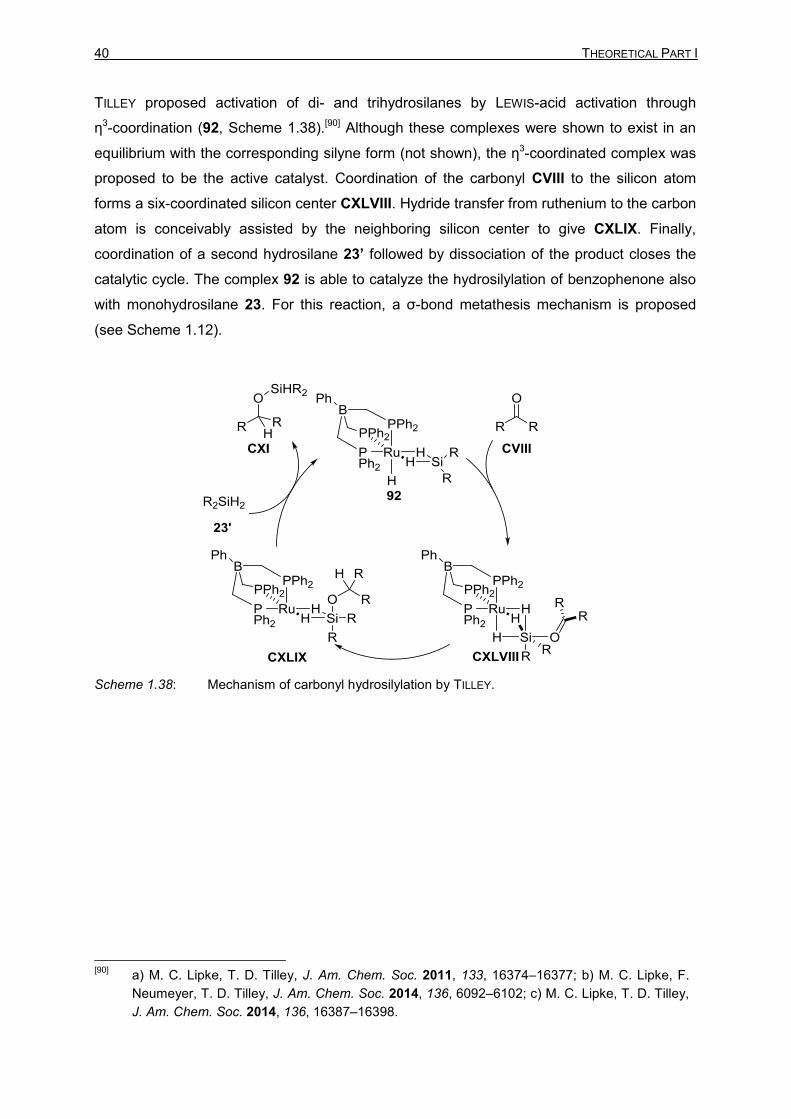
TILLEY proposed activation of di- and trihydrosilanes by LEWIS-acid activation through
η3-coordination (92, Scheme 1.38).[90] Although these complexes were shown to exist in an
equilibrium with the corresponding silyne form (not shown), the η3-coordinated complex was
proposed to be the active catalyst. Coordination of the carbonyl CVIII to the silicon atom
forms a six-coordinated silicon center CXLVIII. Hydride transfer from ruthenium to the carbon
atom is conceivably assisted by the neighboring silicon center to give CXLIX. Finally,
coordination of a second hydrosilane 23’ followed by dissociation of the product closes the
catalytic cycle. The complex 92 is able to catalyze the hydrosilylation of benzophenone also
with monohydrosilane 23. For this reaction, a σ-bond metathesis mechanism is proposed
(see Scheme 1.12).
Scheme 1.38: Mechanism of carbonyl hydrosilylation by TILLEY.
[90]
a) M. C. Lipke, T. D. Tilley, J. Am. Chem. Soc. 2011, 133, 16374–16377; b) M. C. Lipke, F.
Neumeyer, T. D. Tilley, J. Am. Chem. Soc. 2014, 136, 6092–6102; c) M. C. Lipke, T. D. Tilley,
J. Am. Chem. Soc. 2014, 136, 16387–16398.

1 Introduction 41
1.3 Objective
The overview across the mechanisms of metal-catalyzed main-group electrophile generation
shows that the different mechanisms can be divided into two major subgroups: the inner-
sphere and the outer-sphere mechanisms. Notwithstanding this simple classification, the
mechanisms exhibit broad variety in their individual steps. The mechanistic studies have
revealed how the intrinsic LEWIS acidity of group 13 electrophiles can be harnessed as part
of the catalytic cycle. Typically, the main-group atom binds the substrate to the vicinity of the
metal center. The ability of silicon to undergo rehydridization has been used by several
catalyst. The electrophilicity of silicon atom has been increased both by hydride abstraction
to form tricoordinate silicon intermediates as well as by the counterintuitive LEWIS-base
activation to form pentacoordinate silicon intermediates.
LEWIS-acid activation of hydrosilanes has emerged as an important mode of action. In
addition to electron-deficient boranes,[91] electrophilic metal complexes such as the POCOP
pincer complex 73+ introduced by BROOKHART were also proposed to activate hydrosilanes
by a LEWIS-acid mechanism (see Scheme 1.34). In Chapter 2, the precise mechanism of
carbonyl hydrosilylation by the iridium POCOP pincer complex 73+ is investigated.
Replacing expensive late-transition metals with cheap abundant metals, especially with iron,
has been widely studied in several types of reactions,[92] including hydroboration[93] and
hydrosilylation.[94] Unlike the E–H bond activation mechanisms with late-transition metals, the
corresponding mechanisms with abundant early transition metals are often not known in
detail. In Chapter 3, the mechanism of iron-catalyzed carbonyl hydrosilylation using an
iron(0) complex as a precatalyst is studied both experimentally and theoretically.
[91]
M. Oestreich, J. Hermeke, J. Mohr, Chem. Soc. Rev. 2015, 44, 2202–2220. [92]
a) J. I. v. d. Vlugt, Eur. J. Inorg. Chem. 2011, 363–375; b) S. Chakraborty, H. Guan, Dalton
Trans. 2010, 39, 7427–7436. [93]
For selected examples, see: J. Y. Wu, B. Moreau, T. Ritter, J. Am. Chem. Soc. 2009, 131,
12915–12917; b) L. Zhang, D. Peng, X. Leng, Z. Huang, Angew. Chem. 2013, 125, 3764–
3768; Angew. Chem. Int. Ed. 2013, 52, 3676–3680; c) J. V. Obligacion, P. J. Chirik, Org. Lett.
2013, 15, 2680–2683. [94]
a) K. Junge, K. Schröder, M. Beller, Chem. Commun. 2011, 47, 4849–4859; b) M. Zhang, A.
Zhang, Appl. Organomet. Chem. 2010, 24, 751–757; c) R. H. Morris, Chem. Soc. Rev. 2009,
38, 2282–2291.

2 Mechanistic Investigation of Iridium(III) POCOP Pincer Complex 43
2 MECHANISTIC INVESTIGATION INTO BROOKHART’S
IRIDIUM(III) POCOP PINCER COMPLEX-CATALYZED
CARBONYL HYDROSILYLATION[95]
2.1 Introduction
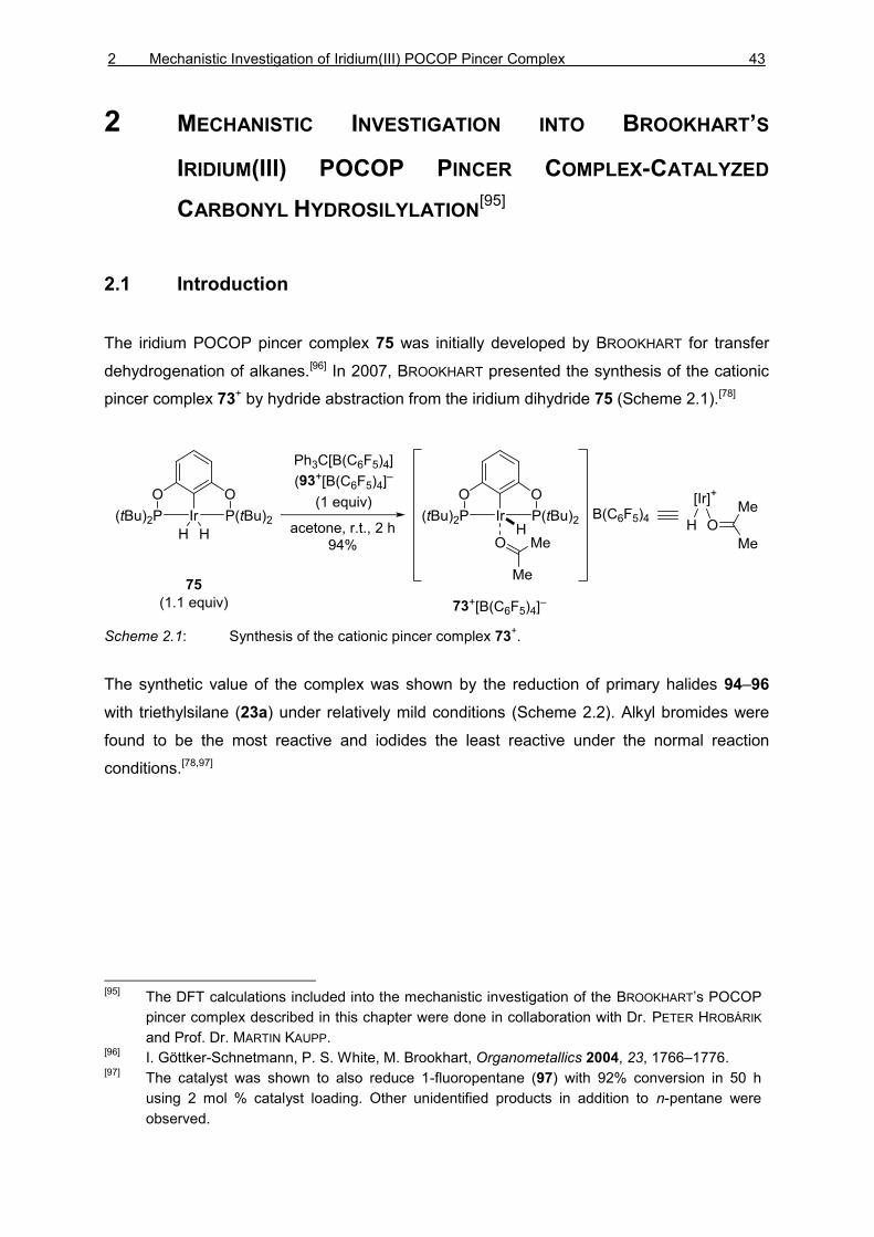
The iridium POCOP pincer complex 75 was initially developed by BROOKHART for transfer
dehydrogenation of alkanes.[96] In 2007, BROOKHART presented the synthesis of the cationic
pincer complex 73+ by hydride abstraction from the iridium dihydride 75 (Scheme 2.1).[78]
Scheme 2.1: Synthesis of the cationic pincer complex 73+.
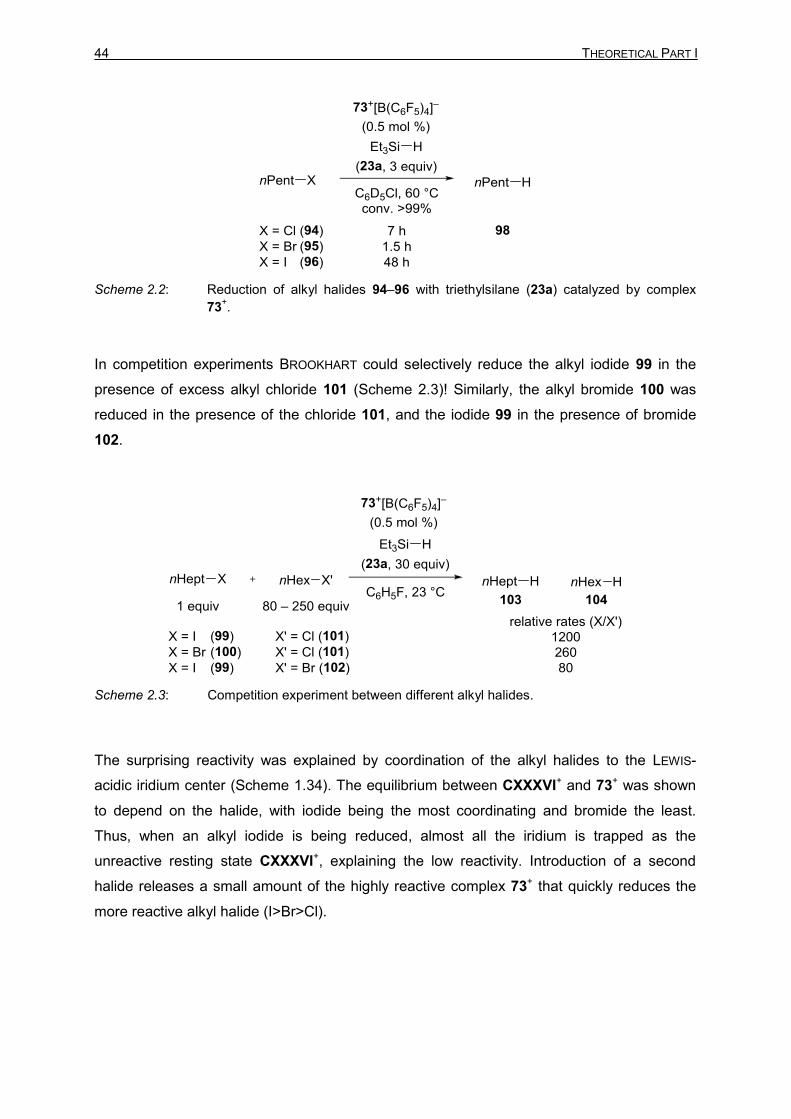
The synthetic value of the complex was shown by the reduction of primary halides 94–96
with triethylsilane (23a) under relatively mild conditions (Scheme 2.2). Alkyl bromides were
found to be the most reactive and iodides the least reactive under the normal reaction
conditions.[78,97]
[95]
The DFT calculations included into the mechanistic investigation of the BROOKHART’s POCOP
pincer complex described in this chapter were done in collaboration with Dr. PETER HROBÁRIK
and Prof. Dr. MARTIN KAUPP. [96]
I. Göttker-Schnetmann, P. S. White, M. Brookhart, Organometallics 2004, 23, 1766–1776. [97]
The catalyst was shown to also reduce 1-fluoropentane (97) with 92% conversion in 50 h
using 2 mol % catalyst loading. Other unidentified products in addition to n-pentane were
observed.
44 THEORETICAL PART I
Scheme 2.2: Reduction of alkyl halides 94–96 with triethylsilane (23a) catalyzed by complex
73+.
In competition experiments BROOKHART could selectively reduce the alkyl iodide 99 in the
presence of excess alkyl chloride 101 (Scheme 2.3)! Similarly, the alkyl bromide 100 was
reduced in the presence of the chloride 101, and the iodide 99 in the presence of bromide
102.
Scheme 2.3: Competition experiment between different alkyl halides.
The surprising reactivity was explained by coordination of the alkyl halides to the LEWIS-
acidic iridium center (Scheme 1.34). The equilibrium between CXXXVI+ and 73+ was shown
to depend on the halide, with iodide being the most coordinating and bromide the least.
Thus, when an alkyl iodide is being reduced, almost all the iridium is trapped as the
unreactive resting state CXXXVI+, explaining the low reactivity. Introduction of a second
halide releases a small amount of the highly reactive complex 73+ that quickly reduces the
more reactive alkyl halide (I>Br>Cl).

2 Mechanistic Investigation of Iridium(III) POCOP Pincer Complex 45
The proposed activation of the silane by the LEWIS-acidic iridium center was further
supported by an X-ray crystal structure of the triethylsilane adduct 74a+ (Scheme 2.4).[98] The
structure distinctly showed the rare η1-coordination of the hydrosilane (η1-74a+).[99] Also in the
1H NMR spectrum a large 1H,29Si coupling (1JSi–H = 79 Hz), typical for η1-coordination, was
measured. The DFT calculations showed however that the η2-isomer η2-74a+ was
energetically nearly identical, thus both isomers would be expected to be present in the
solution during catalysis.[100] For clarity, the assumed equilibrium (η1-74a+ ⇋ η2-74a+) is
referred to as 74a+ throughout this chapter.
Scheme 2.4: Structure of the hydrosilane adduct 74a+ (counteranion B(C6F5)4
– omitted for
clarity).
For the carbonyl hydrosilylation, BROOKHART was able to propose a more detailed
mechanism based on kinetic data as well as in-situ NMR spectroscopy. The initial
coordination of the hydrosilane 23 was found to be under equilibrium strongly favoring the
substrate CVIII or the solvent 105 as a donor, CL+ and 106+ respectively (Scheme 2.5). The
silyl transfer to the oxygen atom of the carbonyl group CVIII was suggested to proceed via
an SN2-Si mechanism analogous to the mechanism proposed for the borane-catalyzed
hydrosilylation.[101] The iridium dihydride 75 was shown to enter an equilibrium with the
[98]
J. Yang, P. S. White, C. K. Schauer, M. Brookhart, Angew. Chem. 2008, 120, 4209–4211;
Angew. Chem. Int. Ed. 2008, 47, 4141–4143. [99]
For a related R3B–η1-H–SiR3 X-ray structure, see: A. Y. Houghton, J. Hurmalainen, A.
Mansikkamäki, W. E. Piers, H. M. Tuononen, Nat. Chem. 2014, 6, 983–988. [100]
η2-74
+ was calculated to be favored over η
1-74
+ by 1.9 kcal mol
–1. The calculations were
performed on a truncated complex using PMe2 instead of P(tBu)2. [101]
a) D. J. Parks, W. E. Piers, J. Am. Chem. Soc. 1996, 118, 9440–9441; b) D. J. Parks, J. M.
Blackwell, W. E. Piers, J. Org. Chem. 2000, 65, 3090–3098; c) S. Rendler, M. Oestreich,
Angew. Chem. 2008, 120, 6086–6089; Angew. Chem. Int. Ed. 2008, 47, 5997–6000; d) K.
Sakata, H. Fujimoto, J. Org. Chem. 2013, 78, 12505–12512; for a recent review on borane-
catalyzed reactions, see: M. Oestreich, J. Hermeke, J. Mohr, Chem. Soc. Rev. 2015, 44,
2202–2220.

46 THEORETICAL PART I
catalytically inactive iridium silyl hydride 107.[102] The hydride transfer from the iridium
dihydride 75 to the carbon atom of the silylcarboxonium ion CXXXV+ furnishes the silyl ether
CXI. The resulting cationic iridium center was proposed to be stabilized by the coordination
of chlorobenzene (105) to give 106+. Based on the kinetic measurements the turnover
frequency of the reaction was determined to be first order in hydrosilane and zero order in
ketone concentration. The rate-determining step was proposed to be either the silyl transfer
(74+→75) or the hydride transfer (75→74+).
Scheme 2.5: Proposed catalytic cycle of carbonyl hydrosilylation (counteranion B(C6F5)4
–
omitted for clarity).
[102]
Based on kinetic measurements during the mechanistic investigation of the ether cleavage
catalyzed by 73+ ref. [81], the iridium silyl hydride 107 was found to be a weaker hydride donor
than the dihydride 75.

2 Mechanistic Investigation of Iridium(III) POCOP Pincer Complex 47
The extensive mechanistic investigations on the iridium POCOP pincer complex 73+-
catalyzed hydrosilylation reactions by BROOKHART established a rather clear understanding
of the fundamental steps of the mechanisms involved in these reactions. First, the cationic
hydrosilane complex 74+ exists under equilibrium, strongly favoring complexes CL+ and
106+. Once complex 74+ enters the catalytic cycle, the silyl transfer to the LEWIS-basic
substrate takes place presumably via an SN2-Si mechanism. The formed iridium dihydride 75
is proposed to act as the active hydride donor. However, the detailed mechanisms of the silyl
and the hydride transfer steps were not verified.
2.2 Mechanistic Investigation into Iridium POCOP Pincer Complex-
Catalyzed Carbonyl Hydrosilylation
2.2.1 Hydrosilylation Using Silicon-Stereogenic Hydrosilanes
The carbonyl hydrosilylation mechanism by BROOKHART’s pincer complex had been
proposed to go through a LEWIS-acid activation of the hydrosilane CLI,[79] similarly to the
mechanism of the B(C6F5)3 (108)-catalyzed hydrosilylation proposed by PIERS and co-
workers (Scheme 2.6).[101a,b] The proposed mechanism was later verified by OESTREICH
using silicon-stereogenic hydrosilanes.[101c] The observed inversion at the silicon atom
proved the SN2-Si mechanism.

48 THEORETICAL PART I
Scheme 2.6: B(C6F5)3 (108) and iridium complex 73+-catalyzed hydrosilylation of ketone 109
(counteranion B(C6F5)4– omitted for clarity).
To investigate the stereochemical course at the silicon atom, the hydrosilylation of
acetophenone catalyzed by iridium complex 73+ was performed under the standard
conditions reported by BROOKHART using silicon-stereogenic silanes 23b and 23c. We began
our study with the cyclic silicon-stereogenic hydrosilane (S)-23b used earlier in the
investigation of the B(C6F5)3 (108)-catalyzed hydrosilylation mechanism.[101c] The reaction
between acetophenone (109) and the rigid hydrosilane (S)-23b (d.r. = 97:3) was readily
catalyzed by the pincer complex 73+. The silyl ether 111b was isolated in good yield as a
mixture of diastereomers (Table 2.1, entry 1). The ratio of diastereomers (d.r. = 55:45)
however proved to be significantly lower than in the case of B(C6F5)3 (108) (d.r. = 74:26).
When the silyl ether 111b was cleaved with DIBAL−H (9b) under the standard conditions[103]
the hydrosilane 23b was recovered with a negligible excess of the opposite enantiomer
(e.r. = 49:51). Also, no chiral induction was obtained at the carbon stereocenter of the
alcohol 112 (e.r. = 49:51). The reaction with one-to-one ratio of ketone and hydrosilane was
found to be rather sluggish and required prolonged reaction times (20 h).[104] To see whether
the observed loss of enantiomeric purity occurs due to the extended reaction time,
hydrosilane loading was increased from one to four equivalents (entry 2). The additional
hydrosilane (S)-23b significantly decreased the required reaction time, and the reaction was
[103]
Known to proceed with retention at silicon atom: M. Oestreich, G. Auer, M. Keller, Eur. J. Org.
Chem. 2005, 184–195. [104]
Hydrosilylation of acetophenone 109 with triethylsilane (23a, 3 equiv) reaches full conversion
in 20 min.

2 Mechanistic Investigation of Iridium(III) POCOP Pincer Complex 49
completed in 30 min. The unreacted excess hydrosilane (S)-23b was recovered in a good
yield without racemization (e.r. = 94:6). The silyl ether 111b was obtained without change in
diastereomeric ratio (d.r. = 55:45). After reductive cleavage with DIBAL−H (9b), the
hydrosilane 23b was recovered with the inverted absolute configuration in 48:52 ratio of
enantiomers.
Table 2.1: Hydrosilylation of acetophenone (109) with cyclic silicon-stereogenic hydrosilane
(S)-23b catalyzed by iridium complex 73+.
entry
hydrosilane silyl ether recovered
hydrosilane
reformed
hydrosilane alcohol
23b 111b 23b 23b 112
equiv
e.r.[a]
yield (%)
d.r.[b]
yield (%)
e.r.[a]
yield (%)
e.r.[a]
yield (%)
e.r.[a]
1[c] 1.0
97:3
86
55:45 -
79
49:51
69
51:49
2[d] 4.0
97:3
86
55:45
95
94:6
99
48:52
86
51:49
[a] Enantiomeric ratios determined by HPLC analysis using chiral stationary phases; e.r. = S/R.
[b]
Diastereomeric ratio determined by GLC analysis. [c]
Reaction time 20 h. [d]
Reaction time 30 min.
The slight excess of the opposite enantiomer of the hydrosilane indicated towards the
proposed SN2-Si mechanism. Meanwhile, the extensive loss of enantiomeric purity
suggested an additional reaction pathway leading to racemization. Further information was
obtained when the experiment was repeated with the acyclic enantioenriched silicon-
stereogenic hydrosilane 23c. The iridium complex 73+ catalyzed reaction between 109 and
one equivalent of (S)-23c (e.r. = 97:3) gave the corresponding silyl ether 111c in a
59:41 ratio of diastereomers (Table 2.2, entry 1). Again the reductive cleavage gave the

50 THEORETICAL PART I
hydrosilane 23c in slight excess of the opposite enantiomer (e.r. = 48:52) without
stereoinduction on the alcohol 112 (e.r. = 49:51). When the hydrosilane loading was
increased to four equivalents (entry 2), the silyl ether 111c was obtained with a slightly
increased diastereomeric ratio (d.r. = 62:38), however the recovered hydrosilane 23c had
partially racemized (e.r. = 74:26). The reductive cleavage with DIBAL−H (9b) furnished the
reformed hydrosilane (R)-23c with significant enantiomeric ratio in the opposite configuration
(e.r. = 36:64). The alcohol 112 was obtained with low enantiomeric ratio (e.r. = 46:54).
Table 2.2: Hydrosilylation of acetophenone (109) with acyclic silicon-stereogenic hydrosilane
(S)-23c catalyzed by iridium complex 73+.
entry
hydrosilane silyl ether recovered
hydrosilane
reformed
hydrosilane alcohol
23c 111c 23c 23c 112
equiv
e.r.[a]
yield (%)
d.r.[b]
yield (%)
e.r.[a]
yield (%)
e.r [a]
yield (%)
e.r.[a]
1[c] 1.0
97:3
90
59:41 -
85
48:52
99
49:51
2[d] 4.0
97:3
89
62:38
85
74:26
86
36:64
93
46:54
[a] Enantiomeric ratios determined by HPLC analysis using chiral stationary phases; e.r. = S/R.
[b]
Diastereomeric ratio determined by GLC analysis. [c]
Reaction time 20 h. [d]
Reaction time 30 min.
2.2.2 Identification of the Hydride Source
The mechanism of the initial silyl transfer step seemed to proceed in accordance with the
related B(C6F5)3-catalyzed reaction. There is however a significant difference in the hydride
transfer step: in the case of B(C6F5)3 (108), the formed silylcarboxonium ion 110+ and the

2 Mechanistic Investigation of Iridium(III) POCOP Pincer Complex 51
borohydride [HB(C6F4)3]– intermediates are unlikely to dissociate[105] but will rapidly react to
release the desired product and regenerate B(C6F5)3 (108). On the other hand, in the iridium
pincer complex 73+-catalyzed reaction, the silylcarboxonium ion 110+ is formed together with
a neutral iridium dihydride 75. According to the proposed mechanism, this neutral and stable
dihydride 75 would transfer a hydride to the carbon atom of the silylcarboxonium ion 110+
forming a cationic monohydride intermediate 76+ (Scheme 2.7, top). The unsaturated iridium
center would then be coordinated by a donor. We hypothesized that the coordination of the
donor could take place before the hydride transfer to form CLII (Scheme 2.7, bottom). The
plausible donors during the reaction are chlorobenzene (105) used as the solvent, ketone
109, and hydrosilane 23.
Scheme 2.7: Plausible hydride donors.
To study the hydride transfer step, we independently synthesized mixtures of plausible
reactive intermediates and analyzed them using in-situ 1H NMR spectroscopy. According to
the proposed mechanism, silylcarboxonium ion 110a+ would be rapidly reduced to the silyl
ether 111a by iridium dihydride 75. When 75 (ca. 0.5 equiv) was added into a freshly
prepared solution of 110a+,[106] only traces of expected silyl ether 111a were observed
(Scheme 2.8). Instead, the major products were regenerated acetophenone 113+ and
hydrosilane 74a+ resulting from the formal backward reaction (110a+→109): the iridium
dihydride transferred a hydride to the silicon atom, not to the carbon atom. The inability of
the iridium dihydride to generate the desired product strongly suggests that 75 is not the
active hydride donor.
[105]
The dissociation of the ion pair is calculated to be unfavored by 15.2 kcal mol–1
, see ref.
[101d]. [106]
Careful control of the stoichiometry during the synthesis is essential to avoid formation of
bissilylhydronium ion, see: a) M. Nava, C. A. Reed, Organometallics 2011, 30, 4798–4800; b)
S. J. Connelly, W. Kaminsky, D. M. Heinekey, Organometallics 2013, 32 7478–7481.

52 THEORETICAL PART I
Scheme 2.8: Control experiment A (counteranion B(C6F5)4– omitted for clarity).
Hydrosilane 23 was added into the previously formed mixture (Scheme 2.8) and immediate
conversion of 110a+ to the expected silyl ether 111a, and silyl enol ether 114a (ratio ca.
50:50), was observed (Scheme 2.9). The observation of the desired product 111a gave
evidence of the involvement of a second molecule of the hydrosilane in the mechanism.
Scheme 2.9: Control experiment B (counteranion B(C6F5)4– omitted for clarity).
The formation of the enol ether 114a was unexpected and presumably only an artifact due to
extremely high concentration of reactive species under the stoichiometric conditions. To
exclude enol ethers from the effective catalytic cycle we performed hydrosilylation of
trideuteroacetophenone (109-d3). As expected, the desired silyl ether 111a-d3 was obtained
completely deuterated at the methyl position, excluding any enol ether intermediates during
the reaction (Scheme 2.10).
Scheme 2.10: Control experiment to exclude silyl enol ethers 114 as intermediates.

2 Mechanistic Investigation of Iridium(III) POCOP Pincer Complex 53
The strongest donor in the system was expected to be the substrate 109. When iridium
dihydride 75 was added together with ketone 109 into a freshly prepared solution of the
silylcarboxonium ion 110a+, no reaction was observed (Scheme 2.11).[107]
Scheme 2.11: Control Experiment C (counteranion B(C6F5)4– omitted for clarity).
The most abundant hydride source in the reaction mixture is the hydrosilane 23.[108]
Hydrosilanes are known to rapidly deoxygenate silylcarboxonium ions[109] but we needed to
examine whether catalytic amounts of the iridium dihydride 75 would be able to inhibit the
deoxygenation. When iridium dihydride 75 (5 mol %) and hydrosilane 23a (1 equiv) were
added to the freshly prepared silylcarboxonium ion 110a+, we observed immediate
deoxygenation to ethyl benzene (115) (Scheme 2.12).
Scheme 2.12: Control experiment D (counteranion B(C6F5)4– omitted for clarity).
[107]
Addition of hydrosilane 23a into this mixture led to deoxygenation to give ethylbenzene 115
and decomposition. [108]
BROOKHART proposed the hydrosilane 23 as a competing hydride source during the ether
cleavage catalyzed by complex 73+, ref. [81].
[109] a) M. Kira, T. Hino, H. Sakurai, Chem. Lett. 1992, 555–558; b) D. Parks, J. Blackwell, W. E.
Piers, J. Org. Chem. 2000, 65, 3090–3098; c) K. Müther, M. Oestreich, Chem. Commun.
2011, 47, 334–336.

54 THEORETICAL PART I
The control experiments indicated that both the iridium dihydride 75 and hydrosilane 23 were
required for the efficient hydride transfer. BROOKHART had shown that iridium dihydride 75
and hydrosilane 23 are under equilibrium with iridium hydrosilane 107 and dihydrogen
(Scheme 2.13). A mechanism for this formal exchange was not proposed but the reaction
seemed unlikely to proceed via an iridium(I) intermediate CLIV through reductive elimination
of dihydrogen and oxidative addition of hydrosilane. Instead, an elusive intermediate 116
between the two structures is proposed.[110]
Scheme 2.13: Proposed intermediates between iridium dihydride 75 and the iridium silyl hydride
107.
We set out to investigate the equilibrium in detail using in-situ NMR spectroscopy. A mixture
of iridium hydride 75 and hydrosilane 23a was dissolved in toluene-d8 and subjected to NMR
analysis (Scheme 2.14). At room temperature (300 K) the only observable signal in the
hydride region was the iridium dihydride 75 at –17.0 ppm but as soon as the temperature
was lowered to 277 K a new hydride signal could be observed at –8.3 ppm. As the
temperature was lowered further to 197 K the expected silyl hydride 107a became visible at
–15.9 ppm together with a fourth signal at –9.3 ppm. As the temperature was increased
again, identical spectra were obtained proving that the observed changes are reversible and
that the spectra were recorded under equilibrium. Two previously unknown signals were
observed also in the 31P NMR spectra with 1H,31P HMQC correlations to the new 1H NMR
hydride signals. Careful integration of the 1H and 31P NMR signals and comparison of the
ratios of the known complexes 76, 107a, and the two new complexes 116a and 117a
allowed the assignment of both of these new hydride signals to correspond to complexes
with three equivalent or coalescent hydrides.
[110]
The dihydrogen/hydrosilane exchange via 116 could in fact be seen as a σ-CAM process (see
Scheme 1.10).

2 Mechanistic Investigation of Iridium(III) POCOP Pincer Complex 55
Scheme 2.14: Variable temperature 1H NMR spectra of iridium dihydride 75 and triethylsilane
(23a).
The assignment of the trihydrides was supported by DFT calculations (Tables 2.3 and
2.4).[111] Complex 116d was identified as the expected iridium(III) dihydride adduct with an
η1-coordinated hydrosilane whereas the complex 117d could be described as an iridium(V)
complex (Scheme 2.15).
[111]
All DFT calculation performed at B3LYP‐D3(BJ)/ECP/6‐31++G(d,p) level using an SMD
solvation model. Trimethylsilane (23d) was used as a model hydrosilane.

56 THEORETICAL PART I
A similar iridium(V) complex had been proposed by BROOKHART earlier using dihydrosilanes
in the amide reduction but as the silyl transfer intermediate not as the hydride donor.[80]
Importantly the borane complexes investigated and carefully characterized by HEINEKEY
provided us a direct comparison for the hydride signals.[112]
Scheme 2.15: Calculated structures of the iridium complexes 116d and 117d.
[112]
T. J. Hebden, M. C. Denney, V. Pons, P. M. B. Piccoli, T. F. Koetzle, A. J. Schultz, W.
Kaminsky, K. I. Goldberg, D. M. Heinekey, J. Am. Chem. Soc. 2008, 130, 10812–10820.

2 Mechanistic Investigation of Iridium(III) POCOP Pincer Complex 57
Table 2.3: Selected bond parameters and NPA charges
iridium complex
bond parameters
NPA charges length (Å),
[Mayer bond order (in parenthesis)] angle (°)
Ir–H1 Ir–H2 Ir–H3 Ir–Si Si–H[a] α(Ir–H2–Si) Ir H1 H2 H3 Si
[Ir]H2(H–SiMe3)
116d
1.673
(1.003)
1.790
(0.102)
1.653
(0.837)
3.092
(0.091)
1.560
(0.769) 134.7° –0.127 –0.255 –0.200 –0.228 1.600
[Ir]H3SiMe3
117d
1.653
(1.035)
1.632
(0.307)
1.640
(0.851)
2.545
(0.314)
1.852
(0.025) 93.6° –0.263 –0.151 0.009 –0.124 1.417
[Ir]H2
75
1.588
(0.748)
1.606
0.792 –0.277 0.033 –0.009
[Ir]H+
76+
1.537
(0.842) 0.327 0.093
[Ir]HSiMe3
107d
1.587
(0.688)
2.448
(0.616)
2.081
(0.042) –0.324 0.061 1.342
[Ir]H(H–SiMe3)
74d+
1.533
(0.881)
1.806
(0.018)
3.203
(0.010)
1.562
(0.929) 0.090 0.137 –0.259 1.614
[a] The shortest Si–H(2) bond distance.

58 THEORETICAL PART I
The calculated NMR shifts and comparison to the previously reported related complexes
further support the assignment of the hydride signal at –8.3 ppm in the 1H NMR to the iridium
trihydride complex 116 with η1-coordinated hydrosilane. The hydride signal at –9.3 ppm
corresponds to the proposed iridium(V) complex 117.
Table 2.4: Selected NMR spectroscopic data of iridium pincer complexes.
experimental (SiR3 = SiEt3) calculated[a] (SiR3 = SiMe3)
iridium complex δ (1H)
(ppm)
δ (31P)
(ppm)
δ (29Si)
(ppm)
δ (1H)
(ppm)
δ (31P)
(ppm)
116
–8.3
(t, 9.0 Hz)
224 K
183.2 –
–6.8 (H1)
–7.7 (H2)
–6.6 (H3)
172.1 This
work
117
–9.3
(t, 10.5 Hz)
197 K
171.4 –0.7
-7.2 (H1)
–7.9 (H2)
–6.7 (H3)
167.0 This
work
75
–17.0
(t, 8.2 Hz)
300 K
204.2 – –16.5 204.9
ref.
[96],
This
work
107
–15.9
(t, 5.9 Hz)
300 K
188.8 –3.9 –14.0
ref.
[78],
This
work
74+
–4.9 (H1)
–44.2 (H2)
(t, 11.6 Hz)
200 K
–4.4 (H1)
–40.0 (H2)
ref.
[98],
This
work
[a] Chemical shifts calculated at the four-component mDKS level using the PBE exchange correlation
functional in conjunction with Dyall’s triple-ζ basis set on iridium and fully uncontracted IGLO-III basis
sets on the ligand atoms.
By plotting the ratios of the two trihydrides 116a and 117a at 224 and 197 K using the VAN’T
HOFF equation (Equation 1) the enthalpy and entropy of the reaction is estimated to be
ΔH = –19.27 kJ mol–1 and ΔS = –84.35 J mol–1 K, respectively. According to the
thermodynamic values, the isomerization from 116a to 117a is thus favored by enthalpy but
strongly unfavored by entropy.

2 Mechanistic Investigation of Iridium(III) POCOP Pincer Complex 59
𝑙𝑛 𝐾𝑒𝑞 = −∆𝐻
𝑅𝑇+
∆𝑆
𝑅 (1)
The dynamic nature of the hydrosilane 23a coordination to the iridium dihydride 75 was
further studied by an EXSY NMR experiment (Scheme 2.16). At room temperature using
300 ms mixing time, chemical exchange between the hydrides of the free hydrosilane 23a,
iridium dihydride 75, and the iridium trihydride 116a was observed. The measurement shows
that the trihydride 116a is kinetically accessible under the catalytic conditions.
Scheme 2.16: EXSY NMR spectra of iridium dihydride 75 and triethylsilane (23a).
Attempts to grow crystals suitable for X-ray diffraction of the trihydrides 116 and 117 by slow
evaporation of mixtures of dihydride 75 and hydrosilanes 23 led to liberation of dihydrogen
and isolation of iridium silyl hydrides 107 (Scheme 2.17). Due to surrounding heavy atoms,
the hydrogen atom attached to the iridium center could not be located but NMR analysis of

60 THEORETICAL PART I
the crystalline material allowed the unambigous assignment of the complex as the
monohydride 107a. Interestingly, when the NMR sample was subjected to an atmosphere of
dihydrogen and immediately reanalyzed, full conversion into the trihydride 116a was
observed (Scheme 2.18). When a flask containing the red iridium silyl hydride 107 crystals
was subjected to an atmosphere of dihydrogen a color change to orange was observed.
Unfortunately, the crystals concomitantly collapsed into noncrystalline powder, preventing
further X-ray crystallographical analysis.
Scheme 2.17: Molecular structures of the iridium silyl hydride complexes 107a and 107e.

2 Mechanistic Investigation of Iridium(III) POCOP Pincer Complex 61
Scheme 2.18: 1H NMR analysis of iridium complex 107a under argon (bottom) and dihydrogen
(top) atmosphere.
Combined experimental and theoretical experiments indicate iridium trihydride 116 or 117 as
the actual active hydride donor during the catalysis. Neither the experiments nor the
theoretical calculations could however distinguish between the two complexes. Calculated
thermodynamic hydricities of the selected iridium hydrides show that the trihydrides 116 and
117 are the strongest hydride sources (Table 2.5). However, the difference between the two
trihydrides was calculated to be only 0.8 kJ mol–1 favoring 116. Conceivably the other donors
should be able to form similar adducts as 116 with the dihydride. However, unlike the other
donors, only hydrosilane 23 is expected to readily undergo oxidative addition on the iridium
center to form the unique iridium(V) complex 117. Intuitively, this unusual complex 117
seems to be the most probable hydride source.

62 THEORETICAL PART I
Table 2.5: Thermodynamic hydricities of relevant iridium pincer complexes and Me3SiH (23d)
with respect to trityl cation.[a]
hydride source
(M–H)
conjugate
hydride
acceptor (M+)
ΔESCF
(kJ mol–1)
ΔH0
(kJ mol–1)
ΔS0
(J mol–1 K–1)
ΔG0
(kJ mol–1)
[Ir]H2
75
[Ir]H+
76+ –141.1 –130.2 2.5 –130.7
[Ir]H2(H–SiMe3)
116d
[Ir]H(H–SiMe3)+
74d+ –202.8 –190.2 –21.3 –183.8
[Ir]H3SiMe3
117d
[Ir]H(H–SiMe3)+
74d+ –198.3 –189.6 –22.0 –183.0
Me3Si–H
23d
Me3Si+
118d+ 28.6 25.9 –17.5 31.1
[a] Electronic energies including dispersion corrections ESCF, enthalpies H, entropies S and Gibbs
free energies G calculated at the B3LYP-D3(BJ)/ECP/6-31++G(d,p) level using the SMD solvation
model.
When enantioenriched silyl ether (S)-111a was subjected to catalytic conditions, slow
racemization was observed (Scheme 2.19). The control experiment shows that the final
hydride transfer is in fact reversible, i.e. the iridium complex 73+ is able to abstract a hydride
from the carbon atom of silyl ether 111a.
Scheme 2.19: Racemization of enantioenriched silyl ether (S)-111a.
Based on the mechanistic investigation, a refined and partially revised catalytic cycle is
presented (2.20). The reversible hydrosilane coordination to 73+ gives the complex 74+ with
activated hydrosilane. The LEWIS-basic carbonyl oxygen atom then attacks the silicon atom
via an SN2-Si mechanism (119‡+) giving silylcarboxonium ion 110+ with inversion of
stereochemistry at the silicon atom. Subsequent attack of another ketone molecule 109

2 Mechanistic Investigation of Iridium(III) POCOP Pincer Complex 63
leads to racemization at the silicon atom through intermediate 120‡+. The iridium dihydride
75 is activated by a second molecule of hydrosilane 23 to give the iridium trihydrides 116
and 117. Reversible hydride transfer to the silylcarboxonium ion 110+ releases the silyl ether
111 and regenerates the active catalyst 74+.
Scheme 2.20: Revised catalytic cycle of the iridium POCOP pincer complex 73+-catalyzed
hydrosilylation of ketones.
The detailed investigation of the mechanism of the iridium POCOP pincer complex-catalyzed
hydrosilylation led to partial revision of the accepted mechanism and revealed new details
about the mode of action of this important catalyst. Although the work was done using the
ketone hydrosilylation as a model reaction, it is likely that the activation of the iridium
dihydride by another molecule of hydrosilane 23 occurs also during the other reactions
catalyzed by the complex 73+.


3 Mechanistic Investigation of Iron SiNSi Pincer Complex 65
3 MECHANISTIC INVESTIGATION INTO IRON(II) SINSI PINCER
COMPLEX-CATALYZED CARBONYL HYDROSILYLATION[113]
3.1 Synthesis of Iron(0) SiNSi Pincer Complex and Application in the
Carbonyl Hydrosilylation
Unlike their carbon analogs, N-heterocyclic silylene (NHSi) ligands have not been
extensively explored yet. A few interesting examples have shown that these strong σ-donor
ligands might in some cases outperform the standard phosphine ligands as well as widely
applied N-heterocyclic carbenes (NHC).[114] DRIESS and co-workers reported recently the
synthesis of an iron(0) SiNSi complex 124 (Scheme 3.1).[115] The SiNSi ligand 122 was
synthesized in two steps from the stable chlorosilylene 121.[116] Complexation of
tetrakis(trimethylphosphine)iron(0) (123) gave the iron(0) SiNSi pincer complex 124. The
iron(0) complex 124 was found to be catalytically active in the hydrosilylation of ketones but
the mechanism of the reaction remained unexplained. Unlike the mechanisms of late-
transition metal complexes, mechanisms of iron and other abundant-metal complexes are
often not well understood.[94]
Scheme 3.1: Synthesis of the iron(0) SiNSi pincer complex 124 (P = Me3P).
[113]
The mechanistic investigation of the iron SiNSi pincer complexes described in this chapter was
done in collaboration with Dr. DANIEL GALLEGO from the group of Prof. Dr. MATTHIAS DRIESS.
The DFT calculations were performed by Dr. TIBOR SZILVÁSI. [114]
a) D. Gallego, B. Blom, G. Tan, M. Driess in Reference Module in Chemistry, Molecular
Sciences and Chemical Engineering, Elsevier, 2015, p. 1–15; b) B. Blom, D. Gallego, M.
Driess, Inorg. Chem. Front. 2014, 1, 134–148; c) B. Blom, M. Stoelzel, M. Driess, Chem. Eur.
J. 2013, 19, 40–62.
[115] D. Gallego, S. Inoue, B. Blom, M. Driess, Organometallics 2014, 33, 6885–6897.
[116] C.-W. So, H. W. Roesky, J. Magull, R. B. Oswald, Angew. Chem. 2006, 118, 4052–4054;
Angew. Chem. Int. Ed. 2006, 45, 3948–3950.

66 THEORETICAL PART I
3.2 Mechanistic Investigation into Iron SiNSi Pincer Complex-
Catalyzed Carbonyl Hydrosilylation
Under the optimized conditions, iron(0) SiNSi pincer complex 124 (2.5 mol %) is able to
catalyze the hydrosilylation of various acetophenones (Scheme 3.2). The reaction was found
to be relatively inert to electronic variation of the substrate (125 vs. 126), but increased
sterics around the carbonyl group thwarted the reaction (112 vs. 127 vs. 128).
Hydrosilylation of cyclopropyl substituted ketone proceeded efficiently (99% yield) without
opening of the cyclopropyl ring to give 129, contradicting single electron transfer
mechanisms. The cis-4-tert-butyl cyclohexanol (cis-130) was isolated as a single
diastereomer in poor yield (25%).
Scheme 3.2: Iron-catalyzed hydrosilylation of ketones.
Although under the optimized conditions both the electron-rich and the electron-poor
substrates 131 and 132, respectively gave full conversion, a clear difference was seen in a
competition experiment between the methoxy-substituted 131 and the trifluoromethyl-
substituted 132 (Scheme 3.3). Surprisingly, the electron-poor ketone 132 gave full
conversion in only 5 min while the electron-rich ketone 131 had reached only 21%
conversion.

3 Mechanistic Investigation of Iron SiNSi Pincer Complex 67
Scheme 3.3: Competition experiment between electronically different ketones 131 and 132.
We then set out to investigate whether the iron(0) would be the real active catalyst or only a
precatalyst. Heating a mixture of the complex 124 and hydrosilanes 23 led to the formation
of a new iron hydride 133 which after diligent multinuclear NMR analysis was identified as an
iron(II) silyl hydride complex with the hydride resting between the NHSi tert-butyl groups
trans to the trimethylphosphine ligand (Scheme 3.4). The assigned molecular structure was
confirmed by X-ray analysis of 133e.
Scheme 3.4: Isolation of the iron(II) complexes 133 and the molecular structure of 133e
(P = Me3P).

68 THEORETICAL PART I
To verify that the iron(II) complex 133 was the active catalyst being formed in situ from the
iron(0) complex 124, we analyzed the kinetic profiles of each complex (Scheme 3.5). After
1 h, the reaction catalyzed by the iron(II) complex 133f had reached 74% while the iron(0)
complex 124-catalyzed reaction had reached only 15% conversion. The experiment proves
that complex 133 is not only active but also more efficient than the iron(0) complex 124
supporting the hypothesis that the complex 124 is a precatalyst that is transformed into the
active catalyst 133 during the reaction.
Scheme 3.5: Kinetic profiles of iron(0) complex 124 and iron(II) complex 133f.
The structure of complex 133 was puzzling as both the metal center and the hydride were
deeply embedded inside the pincer complex. To probe the reactivity of the hydride, we
performed a series of reactions with deuterium-labeled hydrosilane 23e-d1 (Scheme 3.6).
Firstly, the iron(II) complex 133e was found to slowly undergo H/D scrambling with 23e-d1,
leading to complete scrambling in 24 h.

3 Mechanistic Investigation of Iron SiNSi Pincer Complex 69
Scheme 3.6: H/D scrambling between iron complex 133e and deuterium-labeled hydrosilane
23e-d1.
The hydrosilylation of acetophenone (109) with 23-d1 however gave perplexing results
(Scheme 3.7). The reaction with 23e-d1 (>95% D) gave first low level of deuteration at the
silyl ether 111e (H/D = 48/52 at 2% conversion). Later the deuteration degree increased up
to H/D =36/64 at 25% conversion. When the reaction reached full conversion the H/D ratio
had equilibrated back to H/D = 50/50. Using partially deuterated hydrosilane 23e-d1 (ca.
50% D) led to first low-levels of deuterium incorporation (H/D = 90/10 at 19% conversion).
During the reaction, the ratio again slowly rose towards the equilibrium reaching H/D = 78/22
at 63% conversion.

70 THEORETICAL PART I
Scheme 3.7: Hydrosilylation of acetophenone 109 with deuterium-labeled hydrosilane 23e-d1.
To analyze the results, we must assume that the H/D scrambling between 133e and 23e-d1
takes place early during the reaction releasing a small concentration of undeuterated
hydrosilane 23e. A large kinetic isotope effect would lead into a significantly faster reaction
with the unlabeled 23e. Thus, the reaction would start with low level of deuterium
incorporation. As the reaction proceeds the supply of 23e is depleted and the deuterium-to-
hydrogen ratio starts to increase. Toward the end of the reaction the H/D ratio decreases
approaching equilibrium at 50/50. This unsual behavior would only be explained by H/D
scrambling between complex 133e and the silyl ether 111e. Importantly, the experiment
indicates that the hydride is transferred from the free hydrosilane 23e not the iron(II) complex
133e.
The scrambling between silyl ether 111e and iron complex 133e was investigated by
stoichiometric control experiments (Scheme 3.8). The deuterium-labeled silyl ether 111e-d1
was synthesized by B(C6F5)3 (108)-catalyzed hydrosilylation of acetophenone (109) with
23e-d1. When the deuterium-labeled silyl ether 111e-d1 was subjected to the iron(II) complex
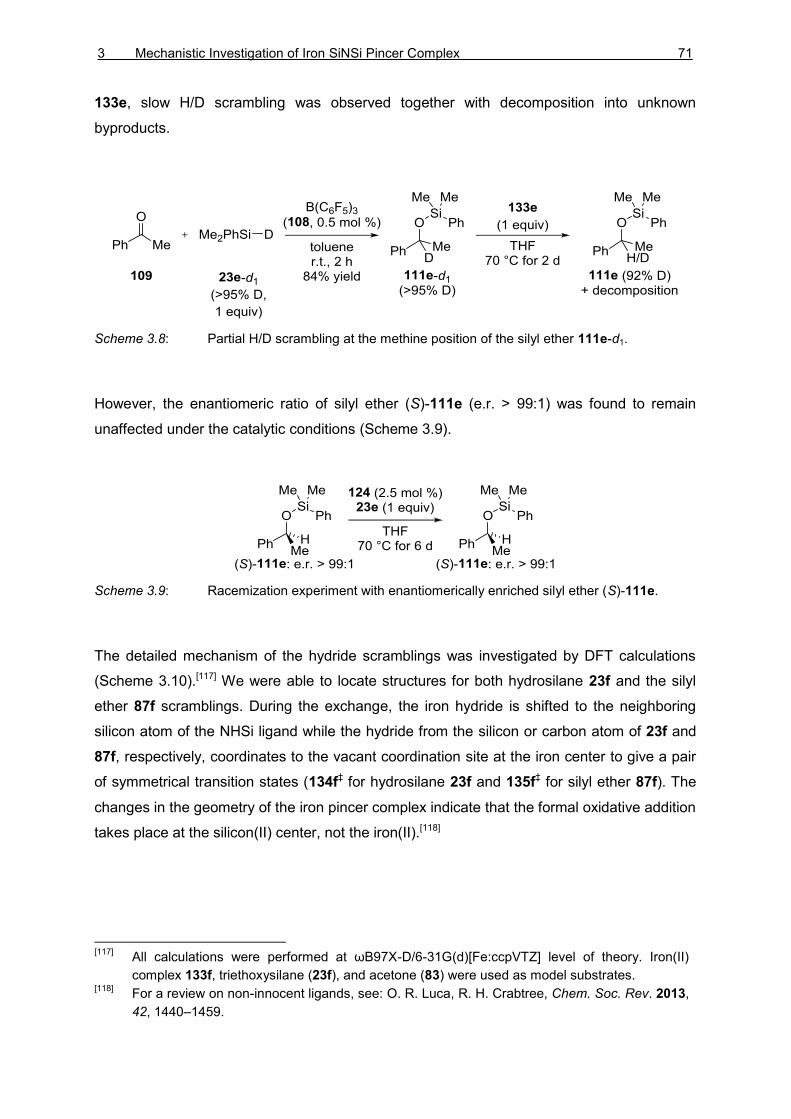
3 Mechanistic Investigation of Iron SiNSi Pincer Complex 71
133e, slow H/D scrambling was observed together with decomposition into unknown
byproducts.
Scheme 3.8: Partial H/D scrambling at the methine position of the silyl ether 111e-d1.
However, the enantiomeric ratio of silyl ether (S)-111e (e.r. > 99:1) was found to remain
unaffected under the catalytic conditions (Scheme 3.9).
Scheme 3.9: Racemization experiment with enantiomerically enriched silyl ether (S)-111e.
The detailed mechanism of the hydride scramblings was investigated by DFT calculations
(Scheme 3.10).[117] We were able to locate structures for both hydrosilane 23f and the silyl
ether 87f scramblings. During the exchange, the iron hydride is shifted to the neighboring
silicon atom of the NHSi ligand while the hydride from the silicon or carbon atom of 23f and
87f, respectively, coordinates to the vacant coordination site at the iron center to give a pair
of symmetrical transition states (134f‡ for hydrosilane 23f and 135f‡ for silyl ether 87f). The
changes in the geometry of the iron pincer complex indicate that the formal oxidative addition
takes place at the silicon(II) center, not the iron(II).[118]
[117]
All calculations were performed at ωB97X-D/6-31G(d)[Fe:ccpVTZ] level of theory. Iron(II)
complex 133f, triethoxysilane (23f), and acetone (83) were used as model substrates. [118]
For a review on non-innocent ligands, see: O. R. Luca, R. H. Crabtree, Chem. Soc. Rev. 2013,
42, 1440–1459.

72 THEORETICAL PART I
Scheme 3.10: Calculated transition states for H/D scrambling between the 133e iron hydride
and methine C–H of the silyl ether 87f and hydrosilane 23f.
The dissociation of the trimethylphosphine (6b) has been suggested to lead into the
exposure of the highly reactive metal center with related iron complexes.[119] Subjection of
iron(II) pincer complex 133e to deuterated trimethylphosphine (6b-d9) did indeed give slow
exchange of phosphine ligands (Scheme 3.11). Attempts to isolate the unsaturated
phosphine-dissociated iron(II) complex with reflux/freeze-pump-thaw cycles led to the
detection of a new iron hydride species that was, with the assistance of DFT calculations
(Scheme 3.12), assigned as 136e-d6 with C6D6 as a ligand. The formation of the new iron
complex was accompanied by the formation of disilane 137e. The role and mechanism of the
disilane formation remains unexplained.
Scheme 3.11: Phosphine-dissociation experiments.
[119]
P. Bhattacharya, J. A. Krause, H. Guan, Organometallics 2011, 30, 4720–4729.

3 Mechanistic Investigation of Iron SiNSi Pincer Complex 73
Scheme 3.12: Calculated formation of benzene adduct 136f via unsaturated iron complex
cis-139f.
The generation of 136e-d6 in the presence of ketone 109 did not produce any silyl ether
111e. Instead, the dissociation of the trimethylphosphine (6b) from the complex 133e was
found to be significantly slower. The increased stability of 133e in the presence of the ketone
109 suggests transient complexation of the two.
To exclude the phosphine-dissociated complex 139 as a potential intermediate during the
reaction, we examined the effect of excess trimethylphosphine (6b) to the reaction (Scheme
3.13). The reaction proceeded smoothly with no indication of inhibition, strongly suggesting
that 136-d6 and related phosphine-dissociated complexes result from decomposition
pathways, and are not part of the actual active catalytic cycle.
Scheme 3.13: Inhibition experiment with excess trimethylphosphine (6b).

74 THEORETICAL PART I
The silyl transfer was investigated with stoichiometric crossover experiments (Scheme 3.14).
As expected, addition of ketone 109 to iron(II) complex 133e did not lead to product
formation. The lability of the silyl group was probed by a silyl-scrambling experiment between
complex 133e and hydrosilane 23g. After 24 h, partial exchange was observed
(133e:133g = 64:25) together with the corresponding phosphine-dissociated products 136e
and 136g as well as mixture of disilanes 137. Importantly, only traces of liberated
hydrosilane 23e were observed, indicating that the observed silyl exchange is in fact only a
side product of the decomposition.
Scheme 3.14: Stoichiometric experiments with ketone 109 and hydrosilane 23g.
Hydrosilylation of ketone 109 with hydrosilane 23g using complex 133e gave silyl ethers
111g and 111e in a ratio of 94:6 (Scheme 3.15). The experiment unequivocally shows that
the silyl group is transferred from the free hydrosilane while the silyl group at the iron center
remains intact.
Scheme 3.15: Hydrosilane-crossover experiment.

3 Mechanistic Investigation of Iron SiNSi Pincer Complex 75
The mechanism of the silyl group transfer was then investigated using enantioenriched
silicon-stereogenic hydrosilane (S)-23c (e.r. > 95:5). The hydrosilylation of 109 with iron(II)
complex 133e proceeded sluggishly and after six days the desired silyl ether 111c was
isolated in 31% yield with low diastereomeric ratio (d.r. = 56:44) (Scheme 3.16). The
unreacted hydrosilane (S)-23c was isolated with unaffected enantiomeric ratio (e.r. > 95:5).
Reductive cleavage of the silyl ether 111c released the hydrosilane (S)-23c with retention of
enantiomeric ratio (e.r. > 95:5). The observed retention of configuration at the silyl ether as
well as the lack of racemization of the unreacted hydrosilane (S)-23c suggests a mechanism
with concerted addition across the carbonyl group.
Scheme 3.16: Hydrosilylation of acetophenone 109 with acyclic silicon-stereogenic hydrosilane
(Si
S)-23c catalyzed by iron(II) complex 133e.
The plausible reaction mechanisms were then thoroughly investigated by DFT calculations.
First an outer-sphere mechanism was considered starting from the energetically unfavored
phosphine-dissociated complex cis-139f (29.2 kcal mol–1) (Scheme 3.17). Coordination of
ketone 83 to the unsaturated iron center was found to lower the energy giving the
intermediate 144f (14.6 kcal mol–1). The activated carbonyl group then undergoes concerted
[2π+2σ]-hydrosilylation through the transition state 145f‡ (33.7 kcal mol–1), releasing the silyl
ether 87f.

76 THEORETICAL PART I
Scheme 3.17: Calculated outer-sphere mechanism.
Isomerization of cis-139f into trans-139f (40.5 kcal mol–1) leads into alternative inner-sphere
mechanisms. Again coordination of ketone 83 to the iron center significantly lowers the
energy to give 148f (24.1 kcal mol–1) (Scheme 3.18). Hydride transfer from the iron to the
carbon atom via 149f‡ (30.9 kcal mol–1) gives the iron alkoxide complex 150f
(22.9 kcal mol–1). Concerted σ-bond metathesis (151f‡, 34.9 kcal mol–1) releases the silyl
ether 87f and regenerates the iron hydride cis-139f. Alternatively, the intermediate 150f
could undergo reductive elimination via 152f‡ (43.1 kcal mol–1) releasing the silyl ether 87f to
give iron(0) complex 153 (36.5 kcal mol–1).

3 Mechanistic Investigation of Iron SiNSi Pincer Complex 77
Scheme 3.18: Calculated inner-sphere mechanisms.
None of the conventional mechanisms give satisfactory fit to the experimental results. In
addition, the calculated activation barriers are too high. Based on the combined results an
unusual mechanism is proposed where the silicon atom of the iron-bound silyl group acts as
the LEWIS acid (Scheme 3.19).[109c,120] In this peripheral mechanism, neither the hydrosilane
23 nor the substrate 83 are in contact with the iron metal center. The adduct 156f between
iron complex 133f and ketone 83 was located as an intermediate (2.8 kcal mol–1). All
attempts to experimentally observe such adducts were not successful. However, the
measurement of the LEWIS acidity of the silyl group by GUTMANN–BECKETT analysis121 led to
slight broadening of the 31P NMR signal of the Et3PO indicating transient reversible
coordination. The hydrosilylation of the activated ketone 156f proceeds via a concerted
[120]
A. L. Liberman-Martin, R. G. Bergman, T. D. Tilley, J. Am. Chem. Soc. 2015, 137, 5328–5331. [121]
V. Gutmann, Coord. Chem. Rev. 1976, 18, 225–255; b) M. A. Beckett, D. S. Brassington, M.
E. Light, M. B. Hursthouse, J. Chem. Soc., Dalton Trans. 2001, 1768–1772.
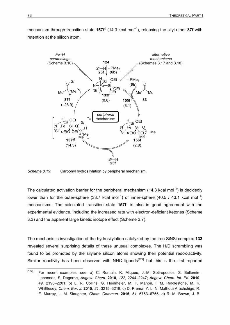
78 THEORETICAL PART I
mechanism through transition state 157f‡ (14.3 kcal mol–1), releasing the silyl ether 87f with
retention at the silicon atom.
Scheme 3.19: Carbonyl hydrosilylation by peripheral mechanism.
The calculated activation barrier for the peripheral mechanism (14.3 kcal mol–1) is decidedly
lower than for the outer-sphere (33.7 kcal mol–1) or inner-sphere (40.5 / 43.1 kcal mol–1)
mechanisms. The calculated transition state 157f‡ is also in good agreement with the
experimental evidence, including the increased rate with electron-deficient ketones (Scheme
3.3) and the apparent large kinetic isotope effect (Scheme 3.7).
The mechanistic investigation of the hydrosilylation catalyzed by the iron SiNSi complex 133
revealed several surprising details of these unusual complexes. The H/D scrambling was
found to be promoted by the silylene silicon atoms showing their potential redox-activity.
Similar reactivity has been observed with NHC ligands[122] but this is the first reported
[122]
For recent examples, see: a) C. Romain, K. Miqueu, J.-M. Sotiropoulos, S. Bellemin-
Laponnaz, S. Dagorne, Angew. Chem. 2010, 122, 2244–2247; Angew. Chem. Int. Ed. 2010,
49, 2198–2201; b) L. R. Collins, G. Hierlmeier, M. F. Mahon, I. M. Riddlestone, M. K.
Whittlesey, Chem. Eur. J. 2015, 21, 3215–3218; c) D. Prema, Y. L. N. Mathota Arachchige, R.
E. Murray, L. M. Slaughter, Chem. Commun. 2015, 51, 6753–6756; d) R. M. Brown, J. B.

3 Mechanistic Investigation of Iron SiNSi Pincer Complex 79
example of non-innocent behavior of NHSi ligands. During the hydrosilylation, the silyl group
and the iron hydride remain at the metal center and the iron center does not directly
participate in the reaction. The silicon atom of the silyl group acts as the LEWIS acid and
catalyzes the reaction at the periphery of the metal center.
Garcia, J. Valjus, C. J. Roberts, H. M. Tuononen, M. Parvez, R. Roesler, Angew. Chem. 2015,
127, 6372–6375; Angew. Chem. Int. Ed. 2015, 54, 6274–6277; e) E. Despagnet-Ayoub, M. K.
Takase, J. A. Labinger, J. E. Bercaw, J. Am. Chem. Soc. 2015, 137, 10500–10503.


4 Summary 81
4 SUMMARY
The mechanism of carbonyl hydrosilylation catalyzed by BROOKHART’s iridium(III) POCOP
pincer complex 73+ was investigated (Scheme 4.1). The experiments with silicon-
stereogenic hydrosilanes confirmed the assumed SN2-Si mechanism of the silyl-transfer step
(119‡+). The extensive loss of enantiomeric purity at the silicon stereocenter indicated that
the hydride transfer would be rate determining and more complicated than expected. A
series of stoichiometric experiments verified an adduct of hydrosilane 23 and the iridium
dihydride 75 as the active hydride source. NMR spectroscopic, X-ray crystallographic, as
well as computational analysis revealed iridium trihydrides 116 and 117 as the potential
hydride donors.
Scheme 4.1: The mechanism of carbonyl hydrosilylation by iridium POCOP pincer complex 73+.
Hydrosilylation of ketones with iron(0) SiNSi pincer complex 124 was found to proceed via
unprecedented mode of action (Scheme 4.2). First, the iron(0) complex 124 undergoes
oxidative addition with the hydrosilane 23 affording the active iron(II) catalyst 133. The
hydride and the silyl ligands on the iron were found to remain at the iron center through the
reaction, excluding inner-sphere mechanisms. The stereochemical orientation and purity of
the silicon-stereogenic hydrosilane (S)-23c was found to remain intact, supporting concerted
hydrosilylation. Finally, supported by DFT calculations, a peripheral mechanism was
proposed where the silicon atom of the silyl ligand acts as a LEWIS acid binding the ketone to
form adduct 156. Concerted hydrosilylation via transition state 157‡ releases the desired silyl
ether CXII.

82 THEORETICAL PART I
Scheme 4.2: The mechanism of carbonyl hydrosilylation by iron SiNSi pincer complex 133.
The mechanistic investigations of BROOKHART’s iridium(III) POCOP pincer 73+ and the iron
SiNSi pincer complex 133 revealed new unexpected mechanistic pathways. These studies
highlight the need for detailed mechanistic understanding of catalytic systems in order to
understand and predict their behavior. It remains to be seen whether the hydrosilane
activation of the metal hydride as found for BROOKHART’s iridium(III) POCOP pincer complex
is a general mode of action. Indeed, several other cationic LEWIS-acidic metal complexes
have been proposed to transfer a hydride from a neutral metal hydride intermediate
analogous to the dihydride 75. The mechanisms of iron-catalyzed hydrosilylations have not
been previously thoroughly investigated. The iron(II) SiNSi pincer complex 133 is admittedly
an unusual iron complex restricting any general conclusions from the mechanistic study. It is
however feasible to assume that the peripheral mechanism is operating in other metal-
catalyzed main-group hydride activation reactions.

THEORETICAL PART II
APPLICATIONS


5 Carbon Dioxide Reduction 85
5 CARBON DIOXIDE REDUCTION
Efficient conversion of carbon dioxide into valuable C1 synthons is one of the greatest
challenges of the chemical community.[123] Reduction[124] and conversion[125] of carbon
dioxide have been extensively studied in the recent years. The following chapter focuses on
the use of main-group electrophiles in the reduction of carbon dioxide into formate,
formaldehyde, methanol, and methane oxidation states.[126]
5.1 Reduction of Carbon Dioxide into Formate Oxidation State
The first reports of carbon dioxide reduction into formate oxidation state using
borohydrides[127] and aluminum hydrides[128] are already from 1950s. It was shown that
LiBH4, NaBH4, and LiAlH4 readily reduce carbon dioxide into formates. The early
[123]
a) M. Aresta, Carbon Dioxide as Chemical Feedstock; Wiley-VCH: Weinheim, Germany, 2010;
b) G. A. Olah, A. Goeppert, G. K. S. Prakash, Beyond Oil and Gas: The Methanol Economy;
Wiley-VCH: Weinheim, Germany, 2006; c) G. A. Olah, Angew. Chem. 2005, 117, 2692–2696;
Angew. Chem. Int. Ed. 2005, 44, 2636–2639; d) T. J. Marks et al., Chem. Rev. 2001, 101,
953–996. [124]
For recent reviews of carbon dioxide reduction, see: a) F. J. Fernández-Alvarez, A. M. Aitani,
L. A. Oro, Catal. Sci. Technol. 2014, 4, 611–624; b) Y.-N. Li, R. Ma, L.-N. He, Z.-F. Diao,
Catal. Sci. Technol. 2014, 4, 1498–1512; c) C. Costentin, M. Robert, J.-M. Savéant, Chem.
Soc. Rev. 2013, 42, 2423–2436; d) G. Centi, E. A. Quadrelli, S. Perathoner, Energy Environ.
Sci. 2013, 6, 1711–1731; e) Y. Oh, X. Hu, Chem. Soc. Rev. 2013, 42, 2253–2261; f) E. E.
Benson, C. P. Kubiak, A. J. Sathrum, J. M. Smieja, Chem. Soc. Rev. 2008, 38, 89–99. [125]
For recent reviews of carbon dioxide conversion, see: a) C. Maeda, Y. Miyazaki, T. Ema,
Catal. Sci. Technol. 2014, 4, 1482–1497; b) M. Cokoja, C. Bruckmeier, B. Rieger, W. A.
Herrmann, F. E. Kühn, Angew. Chem. 2011, 123, 8662–8690; Angew. Chem. Int. Ed. 2011,
50, 8510–8537; c) M. Peters, B. Köhler, W. Kuckshinrichs, W. Leitner, P. Markewitz, T. E.
Müller, ChemSusChem 2011, 4, 1216–1240; d) S. N. Riduan, Y. Zhang, Dalton Trans. 2010,
39, 3347–3357. [126]
For reduction of carbon dioxide into carbon monoxide, see: a) D. S. Laitar, P. Müller, J. P.
Sadighi, J. Am. Chem. Soc. 2005, 127, 17196–17197; b) L. Gu, Y. Zhang, J. Am. Chem. Soc.
2010, 132, 914–915; c) C. Kleeberg, M. S. Cheung, Z. Lin, T. B. Marder, J. Am. Chem. Soc.
2011, 133, 19060–19063, d) R. Dobrovetsky, D. W. Stephan, Angew. Chem. 2013, 125,
2576–2579; Angew. Chem. Int. Ed. 2013, 52, 2516–2519; e) C. Lescot, D. U. Nielsen, I. S.
Makarov, A. T. Lindhardt, K. Daasbjerg, T. Skrydstrup, J. Am. Chem. Soc. 2014, 136, 6142–
6147; f) S. Bagherzadeh, N. P. Mankad, J. Am. Chem. Soc. 2015, 137, 10898–1090. [127]
a) J. G. Burr, Jr., W. G. Brown, H. E. Heller, J. Am. Chem. Soc. 1950, 72, 2560–2562; b) T.
Wartik, R. K. Pearson, J. Am. Chem. Soc. 1955, 77, 1075–1075; c) T. Wartik, R. K. Pearson,
J. Inorg. Nucl. Chem. 1958, 7, 404–411; d) R. K. Pearson, T. Wartik, U.S. Patent 2872474,
1959. [128]
A. E. Finholt, E. C. Jacobson, J. Am. Chem. Soc. 1952, 74, 3943–3944.

86 THEORETICAL PART II
investigations with borohydrides were recently verified, and the resulting
triformatoborohydride was characterized by X-ray diffraction as well as multinuclear NMR
analysis.[129] Unlike the highly reactive borohydrides, pinacolborane (2c) does not react with
carbon dioxide. Copper–NHC complex 158 was needed to catalyze the hydroboration of
carbon dioxide using hydroborane 2c. Under mild conditions, 85% yield of borylformate 159c
was obtained after 24 h (Scheme 5.1).[130]
Scheme 5.1: Copper-catalyzed hydroboration of carbon dioxide into borylformate 159c.
Since the seminal reports by SÜSS-FINK[131] and KOINUMA
[132] in 1981, the hydrosilylation of
carbon dioxide into silylformate has been achieved with variety of catalysts.[133] The copper-
catalyzed hydrosilylation of carbon dioxide reported by BABA and co-workers was shown to
be an exceptionally efficient system for this transformation.[133c,e] Using polymethyl-
hydrosiloxane (PMHS, 23h), the reaction reached 70 000 turnovers at 60 °C in 24 h
(Scheme 5.2).
[129]
I. Knopf, C. C. Cummins, Organometallics 2015, 34, 1601–1603. [130]
R. Shintani, K. Nozaki, Organometallics 2013, 32, 2459–2462. [131]
G. Süss-Fink, J. Reiner, J. Organomet. Chem. 1981, 221, C36–C38. [132]
H. Koinuma, F. Kawakami, H. Kato, H. Hirai, J. Chem. Soc., Chem. Commun. 1981, 213–214. [133]
a) A. Jansen, H. Görls, S. Pitter, Organometallics 2000, 19, 135–138; b) Ref. [69]; c) K.
Motokura, D. Kashiwame, A. Miyaji, T. Baba, Org. Lett. 2012, 14, 2642–2645; d) Ref [74]; e)
K. Motokura, D. Kashiwame, N. Takahashi, A. Miyaji, T. Baba, Chem. Eur. J. 2013, 19,
10030–10037; f) S. Itagaki, K. Yamaguchi, N. Mizuno, J. Mol. Catal. A: Chem. 2013, 366,
347–352; g) L. Zhang, J. Cheng, Z. Hou, Chem. Commun. 2013, 49, 4782–4784; h) L.
González-Sebastián, M. Flores-Alamo, J. J. García, Organometallics 2013, 32, 7186–7194; i)
V. P. Taori, R. Bandari, M. R. Buchmeiser, Chem. Eur. J. 2014, 20, 3292–3296; j) M. L.
Scheuermann, S. P. Semproni, I. Pappas, P. J. Chirik, Inorg. Chem. 2014, 53, 9463–9465.
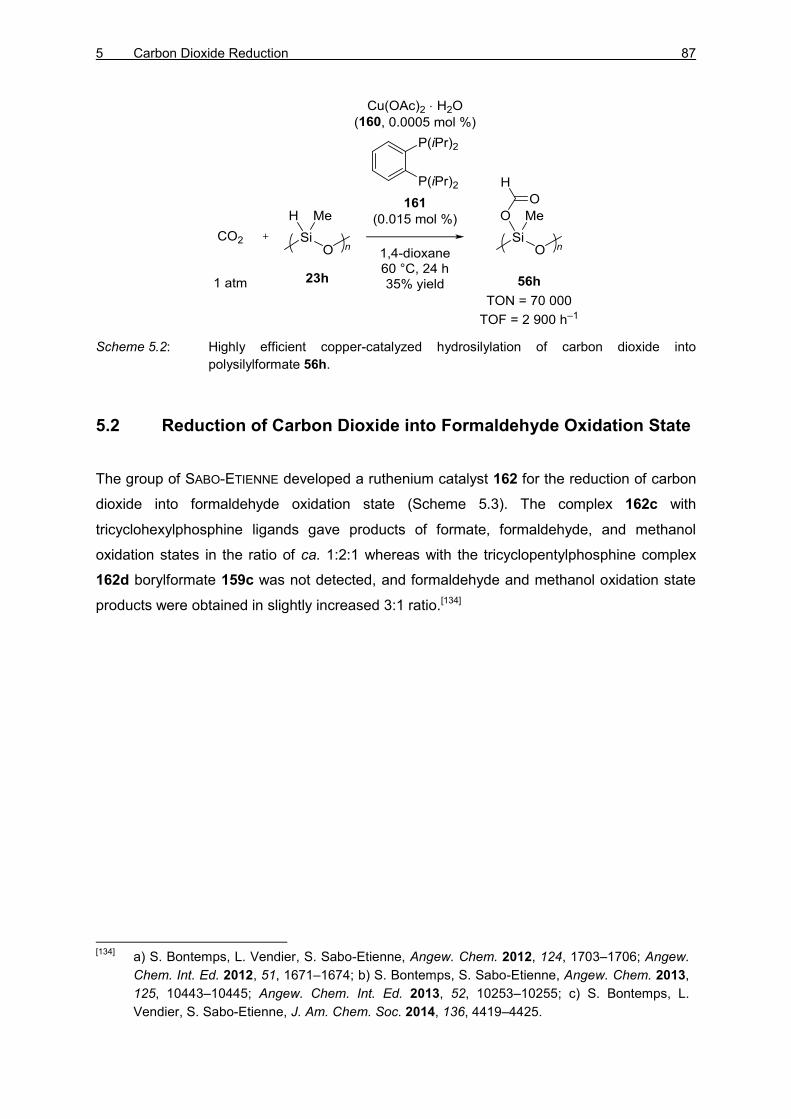
5 Carbon Dioxide Reduction 87
Scheme 5.2: Highly efficient copper-catalyzed hydrosilylation of carbon dioxide into
polysilylformate 56h.
5.2 Reduction of Carbon Dioxide into Formaldehyde Oxidation State
The group of SABO-ETIENNE developed a ruthenium catalyst 162 for the reduction of carbon
dioxide into formaldehyde oxidation state (Scheme 5.3). The complex 162c with
tricyclohexylphosphine ligands gave products of formate, formaldehyde, and methanol
oxidation states in the ratio of ca. 1:2:1 whereas with the tricyclopentylphosphine complex
162d borylformate 159c was not detected, and formaldehyde and methanol oxidation state
products were obtained in slightly increased 3:1 ratio.[134]
[134]
a) S. Bontemps, L. Vendier, S. Sabo-Etienne, Angew. Chem. 2012, 124, 1703–1706; Angew.
Chem. Int. Ed. 2012, 51, 1671–1674; b) S. Bontemps, S. Sabo-Etienne, Angew. Chem. 2013,
125, 10443–10445; Angew. Chem. Int. Ed. 2013, 52, 10253–10255; c) S. Bontemps, L.
Vendier, S. Sabo-Etienne, J. Am. Chem. Soc. 2014, 136, 4419–4425.

88 THEORETICAL PART II
Scheme 5.3: Hydroboration of carbon dioxide using ruthenium complex 162.
Recently, SABO-ETIENNE and BONTEMPS reported a highly selective iron-catalyzed
hydroboration of carbon dioxide in bis(boryl)acetal 164d (Scheme 5.4).[135] It is worth
mentioning that, although (9-BBN)2 (2d) does not reduce carbon dioxide, the control
experiment with (9-BBN)2 (2d) and 1,2-bis(dimethylphosphino)ethane ligand gave borylated
products 164d and 166d. The conversion and the selectivity were however significantly
lower: 4% conversion at 60 °C after 47 min with an 164d:166d ratio 77:23.
[135]
G. Jin, G. Werncke, Y. Escudié, S. Sabo-Etienne, S. Bontemps, J. Am. Chem. Soc. 2015,
137, 9563–9566.

5 Carbon Dioxide Reduction 89
Scheme 5.4: Iron-catalyzed hydroboration of carbon dioxide into formaldehyde oxidation state.
The selective hydrosilylation of carbon dioxide into bis(silyl)acetal 168a was first achieved by
BERKE[136]
and PIERS[137] in 2013 (Scheme 5.5). The rhenium/B(C6F5)3 complex 170 used by
BERKE and co-workers furnished acetal 168a in 89% yield and with good chemoselectivity
(168a:169a = 97:3). The scandium/B(C6F5)3 complex 171 was found to be a highly active
and selective catalyst, giving 94% yield of 168a as the sole silicon-containing product after
96 h.
[136]
Y. Jiang, O. Blacque, T. Fox, H. Berke, J. Am. Chem. Soc. 2013, 135, 7751–7760. [137]
F. A. LeBlanc, W. E. Piers, M. Parvez, Angew. Chem. 2013, 126, 808–811; Angew. Chem. Int.
Ed. 2014, 53, 789–792.

90 THEORETICAL PART II
Scheme 5.5: Hydrosilylation of carbon dioxide into formaldehyde oxidation state.
5.3 Reduction of Carbon Dioxide into Methanol Oxidation State
Several efficient catalysts have been employed in the selective hydroboration of carbon
dioxide into methanol oxidation state.[138] One of the simplest, but also most powerful
systems was reported by STEPHAN (Table 5.1, entry 1).[138g] The bulky phosphine 6e was
able to catalyze the reaction under relatively mild conditions via formation of a frustrated
LEWIS pair (FLP)[139] with the bulky hydroborane 2d. FLP activation of carbon dioxide was
[138]
a) S. Chakraborty, J. Zhang, J. A. Krause, H. Guan, J. Am. Chem. Soc. 2010, 132, 8872–
8873; b) M. J. Sgro, D. W. Stephan, Angew. Chem. 2012, 124, 11505–11507; Angew. Chem.
Int. Ed. 2012, 51, 11343–11345; c) M.-A. Courtemanche, M.-A. Légaré, L. Maron, F.-G.
Fontaine, J. Am. Chem. Soc. 2013, 135, 9326–9329; d) C. Das Neves Gomes, E. Blondiaux,
P. Thuéry, T. Cantat, Chem. Eur. J. 2014, 20, 7098–7106; e) T. Wang, D. W. Stephan, Chem.
Eur. J. 2014, 20, 3036–3039; f) M. D. Anker, M. Arrowsmith, P. Bellham, M. S. Hill, G. Kociok-
Köhn, D. J. Liptrot, M. F. Mahon, C. Weetman, Chem. Sci. 2014, 5, 2826–2830; g) T. Wang,
D. W. Stephan, Chem. Commun. 2014, 50, 7007–7010; h) K. Fujiwara, S. Yasuda, T. Mizuta,
Organometallics 2014, 33, 6692–6695; i) R. Pal, T. L. Groy, R. J. Trovitch, Inorg. Chem. 2015,
54, 7506–7515; j) Y. Yang, M. Xu, D. Song, Chem. Commun. 2015, 51, 11293–11296; k) J. A.
B. Abdalla, I. M. Riddlestone, R. Tirfoin, S. Aldridge, Angew. Chem. 2015, 127, 5187–5191;
Angew. Chem. Int. Ed. 2015, 54, 5098–5102. [139]
For reviews of frustrated LEWIS pair chemistry, see: a) D. W. Stephan, Acc. Chem. Res. 2015,
48, 306–316; b) M. Alcarazo, Synlett 2014, 1519–1520; c) D. W. Stephan, G. Erker, Chem.

5 Carbon Dioxide Reduction 91
later utilized by MARON and FONTAINE using phosphineborane 172 (entry 2).[138c]
Diazafluorenide 173 used initially as a bidentate ligand[140] was shown to catalytically activate
carbon dioxide.[138j] The hydroboration was achieved with different hydroboranes, including
(9-BBN)2 (2d), pinB–H (2c), and catB–H (2a) (entry 3). The nickel POCOP pincer complex
174 reported by GUAN in 2010 remains one of the most efficient and selective catalysts for
this transformation (entry 4).[138a] Very recently ALDRIDGE reported that the unusual gallium
hydride 175 was also catalytically active in the carbon dioxide hydroboration.[138k] The
catalytic reactivity was however low and the reaction required 10 mol % catalyst loading to
reach completion (entry 5). Economically the most efficient method to transform carbon
dioxide into methanol oxidation state was reported in 2014 by MIZUTA.[138h] The commercial
BH3 · THF solution was found to react with carbon dioxide (1 atm) at room temperature to
give trimethoxyboroxine. When the authors used purified[141] borane complex, no reaction
was observed. However, the addition of NaBH4 (0.5 mol %) restored the activity, and
impressive turnover numbers were achieved (entry 6).
Sci. 2014, 5, 2625–2641; d) Top. Curr. Chem. (Eds. G. Erker, D. W. Stephan), Springer,
Berlin, Heidelberg, 2013, vol. 332; e) Top. Curr. Chem. (Eds. G. Erker, D. W. Stephan),
Springer, Berlin, Heidelberg, 2013, vol. 334; f ) D. W. Stephan, G. Erker, Angew. Chem. 2010,
122, 50–81; Angew. Chem. Int. Ed. 2010, 49, 46–76; g) D. W. Stephan, Org. Biomol. Chem.
2008, 6, 1535–1539; h) A. L. Kenward, W. E. Piers, Angew. Chem. 2008, 120, 38–42; Angew.
Chem. Int. Ed. 2008, 47, 38–41. [140]
a) V. T. Annibale, D. Song, Chem. Commun. 2011, 48, 5416–5418; b) V. T. Annibale, D. A.
Dalessandro, D. Song, J. Am. Chem. Soc. 2013, 135, 16175–16183. [141]
Purified by bulb-to-bulb transfer in vacuo.

92 THEORETICAL PART II
Table 5.1: Selected examples of hydroboration of carbon dioxide into borylated methanol
166.
entry catalyst (mol %) R2B–H p[CO2] T [°C] t [h] Yield TON TOF [h–1]
1[138g] tBu3P (6e)
(0.02)
(9-BBN)2
2d 5 atm 60 32 >99 5 000 156
2[138c] 172
(0.1)
BH3 · SMe2
2b · SMe2 2 atm 70 4 - 2 950 737
3[138j] 173
(1)
catB–H
2a 1.5 atm 70 2 - 97 231
4[138a] 174
(0.2)
catB–H
2a 1 atm r.t. 1 h 61 495 495
5[138k] 175
(10)
pinB–H
2c 1 atm 60 4 >95 10 2.5
6[138h] NaBH4
(0.5)
BH3 · THF
2b · THF 1 atm r.t. 12 87 174 15
The hydroalumination of carbon dioxide into methanol was reported as early as 1948.
Methanol was obtained by simply passing a stream of carbon dioxide through a LiAlH4
solution in diethyl ether.[142]
The corresponding hydrosilylation into silylated methanol has been reported only twice. The
first report in 1989 by EISENBERG using an iridium catalyst (not shown)[143] was followed by
ZHANG and YING in 2009 by an NHC catalyst 177.[144] The insensitivity of the NHC-catalyzed
reaction was demonstrated by using air as the CO2 source (Scheme 5.6).[145]
[142]
R. F. Nystrom, W. H. Yanko, W. Brown, J. Am. Chem. Soc. 1948, 70, 441–441. [143]
T. C. Eisenschmid, R. Eisenberg, Organometallics 1989, 8, 1822–1824. [144]
a) S. N. Riduan, Y. Zhang, J. Y. Ying, Angew. Chem. 2009, 121, 3372–3375; Angew. Chem.
Int. Ed. 2009, 48, 3322–3325; for mechanistic investigations, see: b) F. Huang, L. Zhao, H. Li.
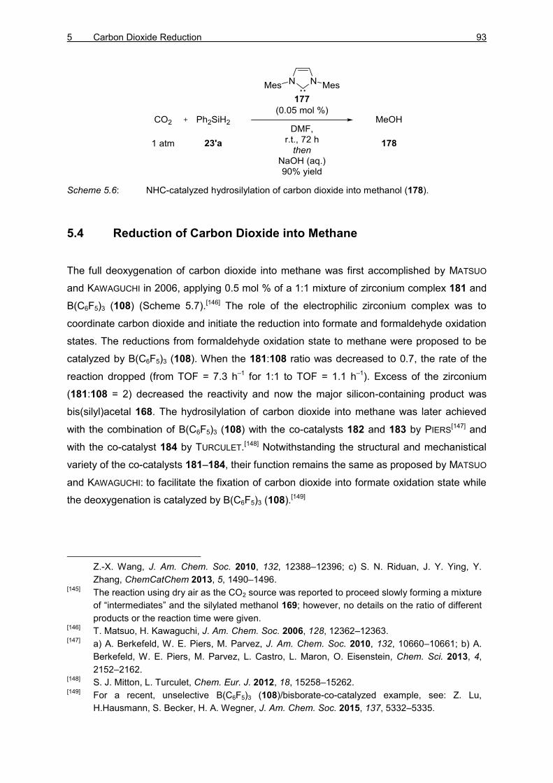
5 Carbon Dioxide Reduction 93
Scheme 5.6: NHC-catalyzed hydrosilylation of carbon dioxide into methanol (178).
5.4 Reduction of Carbon Dioxide into Methane
The full deoxygenation of carbon dioxide into methane was first accomplished by MATSUO
and KAWAGUCHI in 2006, applying 0.5 mol % of a 1:1 mixture of zirconium complex 181 and
B(C6F5)3 (108) (Scheme 5.7).[146] The role of the electrophilic zirconium complex was to
coordinate carbon dioxide and initiate the reduction into formate and formaldehyde oxidation
states. The reductions from formaldehyde oxidation state to methane were proposed to be
catalyzed by B(C6F5)3 (108). When the 181:108 ratio was decreased to 0.7, the rate of the
reaction dropped (from TOF = 7.3 h–1 for 1:1 to TOF = 1.1 h–1). Excess of the zirconium
(181:108 = 2) decreased the reactivity and now the major silicon-containing product was
bis(silyl)acetal 168. The hydrosilylation of carbon dioxide into methane was later achieved
with the combination of B(C6F5)3 (108) with the co-catalysts 182 and 183 by PIERS[147] and
with the co-catalyst 184 by TURCULET.[148] Notwithstanding the structural and mechanistical
variety of the co-catalysts 181–184, their function remains the same as proposed by MATSUO
and KAWAGUCHI: to facilitate the fixation of carbon dioxide into formate oxidation state while
the deoxygenation is catalyzed by B(C6F5)3 (108).[149]
Z.-X. Wang, J. Am. Chem. Soc. 2010, 132, 12388–12396; c) S. N. Riduan, J. Y. Ying, Y.
Zhang, ChemCatChem 2013, 5, 1490–1496. [145]
The reaction using dry air as the CO2 source was reported to proceed slowly forming a mixture
of “intermediates” and the silylated methanol 169; however, no details on the ratio of different
products or the reaction time were given. [146]
T. Matsuo, H. Kawaguchi, J. Am. Chem. Soc. 2006, 128, 12362–12363. [147]
a) A. Berkefeld, W. E. Piers, M. Parvez, J. Am. Chem. Soc. 2010, 132, 10660–10661; b) A.
Berkefeld, W. E. Piers, M. Parvez, L. Castro, L. Maron, O. Eisenstein, Chem. Sci. 2013, 4,
2152–2162. [148]
S. J. Mitton, L. Turculet, Chem. Eur. J. 2012, 18, 15258–15262. [149]
For a recent, unselective B(C6F5)3 (108)/bisborate-co-catalyzed example, see: Z. Lu,
H.Hausmann, S. Becker, H. A. Wegner, J. Am. Chem. Soc. 2015, 137, 5332–5335.

94 THEORETICAL PART II
Scheme 5.7: Hydrosilylation of carbon dioxide into methane using B(C6F5)3 (108) and co-
catalyst.
Strong LEWIS acids 73+ and 185c+ were also successfully used in the exhaustive
hydrosilylation of carbon dioxide (Scheme 5.8). BROOKHART was able to use only
0.0077 mol % of iridium POCOP pincer 73+ to hydrosilylate carbon dioxide (1 atm) with
dimethylphenylsilane (23e).[82] After 72 h at room temperature, the reaction had reached ca.
8 300 turnovers. The highly reactive diethyl aluminum cation 185c+ by WEHMSCHULTE could
be used catalytically as well but higher catalyst loading (10 mol %) and elevated temperature
(80 °C) were required.[150] An alternative aluminum cation was later utilized by the same
group in CO2 reduction but the selectivities were diminished (not shown).[151]
Scheme 5.8: LEWIS acid-catalyzed exhaustive hydrosilylation of carbon dioxide.
[150]
M. Khandelwal, R. J. Wehmschulte, Angew. Chem. 2012, 124, 7435–7439; Angew. Chem. Int.
Ed. 2012, 51, 7323–7326. [151]
R. J. Wehmschulte, M. Saleh, D. G. Powell, Organometallics 2013, 32, 6812–6819.

5 Carbon Dioxide Reduction 95
5.5 Summary
The reduction of carbon dioxide with main-group electrophiles has been achieved with
variety of catalysts. Several efficient and selective methods to access formate and methane
oxidation states have been described. However, accessing the intermediate oxidation states
remains a great challenge. While a growing number of selective methods to access
methanol oxidation state are being reported, only three examples[135–137] of selective
reduction of carbon dioxide into formaldehyde oxidation state using main-group electrophiles
have been reported to date.
5.6 Ruthenium Thiolate-Catalyzed Hydrosilylation of Carbon Dioxide
The ruthenium thiolate complex 25+ was applied to the activation of H–H,[30] Si–H, and B–H
bonds in reductions[72] and dehydrogenative couplings.[73] The distinct activation mode,[71]
and the unusual reactivity observed in the previously reported reactions led to expect that
carbon dioxide reduction with 25+ could provide unconventional results (Scheme 5.9).
Scheme 5.9: Ruthenium thiolate 25+-catalyzed hydrosilylation of carbon dioxide.
To be able to detect all possible products (including methane) as well as for measurement of
accurate reaction kinetics, the reactions were run in high-pressure NMR tubes. The initial
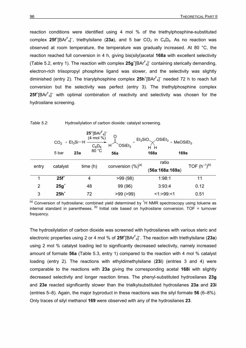
96 THEORETICAL PART II
reaction conditions were identified using 4 mol % of the triethylphosphine-substituted
complex 25f+[BArF4]
–, triethylsilane (23a), and 5 bar CO2 in C6D6. As no reaction was
observed at room temperature, the temperature was gradually increased. At 80 °C, the
reaction reached full conversion in 4 h, giving bis(silyl)acetal 168a with excellent selectivity
(Table 5.2, entry 1). The reaction with complex 25g+[BArF4]
– containing sterically demanding,
electron-rich triisopropyl phosphine ligand was slower, and the selectivity was slightly
diminished (entry 2). The triarylphosphine complex 25h+[BArF4]
– needed 72 h to reach full
conversion but the selectivity was perfect (entry 3). The triethylphosphine complex
25f+[BArF4]
– with optimal combination of reactivity and selectivity was chosen for the
hydrosilane screening.
Table 5.2: Hydrosilylation of carbon dioxide: catalyst screening.
entry catalyst time (h) conversion (%)[a] ratio
(56a:168a:169a) TOF (h–1)[b]
1 25f+ 4 >99 (98) 1:98:1 11
2 25g+ 48 99 (96) 3:93:4 0.12
3 25h+ 72 >99 (>99) <1:>99:<1 0.51
[a] Conversion of hydrosilane; combined yield determined by
1H NMR spectroscopy using toluene as
internal standard in parentheses. [b]
Initial rate based on hydrosilane conversion. TOF = turnover
frequency.
The hydrosilylation of carbon dioxide was screened with hydrosilanes with various steric and
electronic properties using 2 or 4 mol % of 25f+[BArF4]
–. The reaction with triethylsilane (23a)
using 2 mol % catalyst loading led to significantly decreased selectivity, namely increased
amount of formate 56a (Table 5.3, entry 1) compared to the reaction with 4 mol % catalyst
loading (entry 2). The reactions with ethyldimethylsilane (23i) (entries 3 and 4) were
comparable to the reactions with 23a giving the corresponding acetal 168i with slightly
decreased selectivity and longer reaction times. The phenyl-substituted hydrosilanes 23g
and 23e reacted significantly slower than the trialkylsubstituted hydrosilanes 23a and 23i
(entries 5–8). Again, the major byproduct in these reactions was the silyl formate 56 (6–8%).
Only traces of silyl methanol 169 were observed with any of the hydrosilanes 23.

5 Carbon Dioxide Reduction 97
Table 5.3: Hydrosilylation of carbon dioxide: hydrosilane screening.
entry 7a (mol %) hydrosilane time (h) conversion
(%)[a]
ratio
(56:168:169) TOF (h–1)[b]
1 2 Et3SiH
(23a)
47 97 (97) 18:81:<1 11
2 4 4 >99 (>99) 0:>99:0 12
3 2 EtMe2SiH
(23i)
73 70 (69) 6:93:<1 7.8
4 4 11 >99 (97) 7:93:<1 12
5 2 MePh2SiH
(23g)
73 33 (27) 8:91:2 4.5
6 4 36 98 (85) 6:92:1 12
7 2 Me2PhSiH
(23e)
73 63 (60) 8:90:1 5.2
8 4 75 96 (86) 6:92:2 9.5
[a] Conversion of hydrosilane; combined yield determined by
1H NMR spectroscopy using toluene as
internal standard in parentheses. [b]
Initial rate based on hydrosilane conversion. TOF = turnover
frequency.
To test the observed chemoselectivity towards bis(silyl)acetal 168, we used a CO2/Ar
mixture to first selectively synthesize 168i (Scheme 5.10). After 4 days at 80 °C, the reaction
was found to reach a plateau,[152] indicating full consumption of carbon dioxide into
bis(silyl)acetal (168i:169i = 96:4). The reaction was then heated to 150 °C. Slow conversion
of 168i to 169i was observed, and after 7 days the silylated methanol 169i was obtained as
the major product (168i:169i = 25:75).
Scheme 5.10: Temperature-controlled reduction of carbon dioxide into formaldehyde and
methanol oxidation states.
[152]
Followed by the hydrosilane consumption.

98 THEORETICAL PART II
The ruthenium thiolate 25f+ was found able to catalyze the reduction of carbon dioxide using
other main-group hydrides as well. The hydroboranes 2a and 2c used previously in the
dehydrogenative borylation of indoles[31] could be used in the carbon dioxide reduction but
the reactions were slow, giving borylated methanol 166 with excellent selectivity (Table 5.4,
entries 1 and 2). Tin hydrides had not been previously used with the ruthenium thiolate 25+,
and the reaction with tributyltin hydride 16b did not give any conversion (entry 3).[153]
Catalytic activation of aluminum hydrides with well-defined metal complexes has not been
widely applied yet. When a solution of complex 25f+ and DIBAL–H (9b) was subjected to
5 bar of carbon dioxide, fast reaction was observed and in 30 min the solution turned green,
typical for free unsaturated 25+. NMR analysis of the mixture revealed full conversion into a
mixture of products, containing mainly acetal-type compounds (entry 4).[154]
Table 5.4: Hydrosilylation of carbon dioxide: application of other main-group hydrides.
entry E–H time T (°C) conversion
(%)[a]
ratio
(CLVI:CLVII:CLVIII) TOF (h–1)[b]
1 catB–H
(2a) 7 d 120 71 (30) <1:<1:>98 0.21
2 pinB–H
(2c) 7 d 120 45 (27) 2:<1:>97 0.13
3 Bu3Sn–H
(16b) 5 d 80 – – –
4 DIBAL–H
(9b) 30 min r.t. >99 10:85:5[c] 100
[a] Conversion of hydride source; combined yield determined by
1H NMR spectroscopy using toluene
as internal standard in parentheses. [b]
Initial rate based on hydride source conversion. [c]
A mixture of
several formates, acetal-like compounds as well as methoxy groups. TOF = turnover frequency.
[153]
Typically a color change from blue-green into yellow-orange occurs upon the addition of main-
group hydrides into a solution of 25+. In the case of the tin hydride 16b, the solution turned
quickly dark red. [154]
The uncatalyzed reduction of carbon dioxide with DIBAL–H (9b) gave uncontrolled reduction
leading to clogging of the NMR tube used for the reaction, separating the gas and the liquid
phases. 1H NMR analysis of the liquid phase showed no conversion.
5 Carbon Dioxide Reduction 99
In conclusion, an efficient method for the synthesis of bis(silyl)acetals 168 using ruthenium
thiolate complex 25f+ was developed. At lower reaction temperature, the reaction is highly
selective for the reduction to the formaldehyde oxidation state. The observed reactivity is
thought to arise from the relatively low hydricity of the ruthenium hydride 27. Only under
forcing conditions, the further reduction of bis(silyl)acetals 168 into silylated methanol 169
could be accomplished. Even after prolonged reaction times (up to 30 d) at 150 °C, no
exhaustive reduction into methane was observed. The reduction of carbon dioxide with other
main-group electrophiles showed the versatility of the ruthenium thiolate 25+. With
hydroboranes 2, borylated methanol was obtained as the major product. The reaction with
DIBAL–H (9b) gave full conversion at room temperature in 30 min.

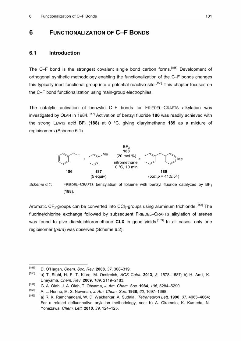
6 Functionalization of C–F Bonds 101
6 FUNCTIONALIZATION OF C–F BONDS
6.1 Introduction
The C–F bond is the strongest covalent single bond carbon forms.[155] Development of
orthogonal synthetic methodology enabling the functionalization of the C–F bonds changes
this typically inert functional group into a potential reactive site.[156] This chapter focuses on
the C–F bond functionalization using main-group electrophiles.
The catalytic activation of benzylic C–F bonds for FRIEDEL–CRAFTS alkylation was
investigated by OLAH in 1984.[157] Activation of benzyl fluoride 186 was readily achieved with
the strong LEWIS acid BF3 (188) at 0 °C, giving diarylmethane 189 as a mixture of
regioisomers (Scheme 6.1).
Scheme 6.1: FRIEDEL–CRAFTS benzylation of toluene with benzyl fluoride catalyzed by BF3
(188).
Aromatic CF3-groups can be converted into CCl3-groups using aluminum trichloride.[158] The
fluorine/chlorine exchange followed by subsequent FRIEDEL–CRAFTS alkylation of arenes
was found to give diaryldichloromethane CLX in good yields.[159] In all cases, only one
regioisomer (para) was observed (Scheme 6.2).
[155]
D. O’Hagan, Chem. Soc. Rev. 2008, 37, 308–319. [156]
a) T. Stahl, H. F. T. Klare, M. Oestreich, ACS Catal. 2013, 3, 1578–1587; b) H. Amii, K.
Uneyama, Chem. Rev. 2009, 109, 2119–2183. [157]
G. A. Olah, J. A. Olah, T. Ohyama, J. Am. Chem. Soc. 1984, 106, 5284–5290. [158]
A. L. Henne, M. S. Newman, J. Am. Chem. Soc. 1938, 60, 1697–1698. [159]
a) R. K. Ramchandani, W. D. Wakharkar, A. Sudalai, Tetrahedron Lett. 1996, 37, 4063–4064;
For a related defluorinative arylation methodology, see: b) A. Okamoto, K. Kumeda, N.
Yonezawa, Chem. Lett. 2010, 39, 124–125.

102 THEORETICAL PART II
Scheme 6.2: Synthesis of dichlorodiarenes through FRIEDEL–CRAFTS alkylation/halide exchange
sequence.
Niobium-catalyzed defluorination has been extensively studied by AKIYAMA.[160] The
intramolecular C–C bond coupling is proposed to occur via fluorine substituted carbene
intermediate 196. Insertion of the carbene 196 into the neighboring C–H bond followed by
subsequent hydrodefluorination furnishes the fluorene 197 (Scheme 6.3).[160e]
Scheme 6.3: Niobium-catalyzed defluorinative C–C bond coupling.
[160]
a) K. Fuchibe, T. Akiyama, Synlett 2004, 1282–1284; b) K. Fuchibe, T. Akiyama, J. Am.
Chem. Soc. 2006, 128, 1434–1435; c) K. Fuchibe, Y. Ohshima, K. Mitomi, T. Akiyama, Org.
Lett. 2007, 9, 1497–1499; d) K. Fuchibe, Y. Ohshima, K. Mitomi, T. Akiyama, J. Fluorine
Chem. 2007, 128, 1158–1167; e) K. Fuchibe, K. Mitomi, R. Suzuki, T. Akiyama, Chem. Asian.
J. 2008, 3, 261–271; f) K. Fuchibe, T. Kaneko, K. Mori, T. Akiyama, Angew. Chem. 2009, 121,
8214–8217; Angew. Chem. Int. Ed. 2009, 48, 8070–8073; g) T. Akiyama, K. Atobe, M.
Shibata, K. Mori, J. Fluorine Chem. 2013, 152, 81–83; for a recent example using TiCl4 and
hydrosilanes, see: h) T. Yamada, K. Saito, T. Akiyama, Adv. Synth. Catal. 2016, 358, 62–66.
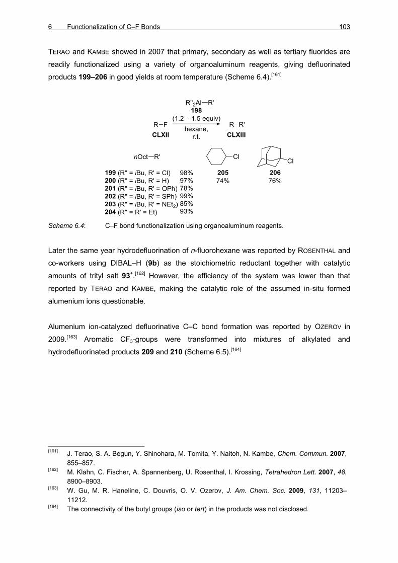
6 Functionalization of C–F Bonds 103
TERAO and KAMBE showed in 2007 that primary, secondary as well as tertiary fluorides are
readily functionalized using a variety of organoaluminum reagents, giving defluorinated
products 199–206 in good yields at room temperature (Scheme 6.4).[161]
Scheme 6.4: C–F bond functionalization using organoaluminum reagents.
Later the same year hydrodefluorination of n-fluorohexane was reported by ROSENTHAL and
co-workers using DIBAL–H (9b) as the stoichiometric reductant together with catalytic
amounts of trityl salt 93+.[162] However, the efficiency of the system was lower than that
reported by TERAO and KAMBE, making the catalytic role of the assumed in-situ formed
alumenium ions questionable.
Alumenium ion-catalyzed defluorinative C–C bond formation was reported by OZEROV in
2009.[163] Aromatic CF3-groups were transformed into mixtures of alkylated and
hydrodefluorinated products 209 and 210 (Scheme 6.5).[164]
[161]
J. Terao, S. A. Begun, Y. Shinohara, M. Tomita, Y. Naitoh, N. Kambe, Chem. Commun. 2007,
855–857. [162]
M. Klahn, C. Fischer, A. Spannenberg, U. Rosenthal, I. Krossing, Tetrahedron Lett. 2007, 48,
8900–8903. [163]
W. Gu, M. R. Haneline, C. Douvris, O. V. Ozerov, J. Am. Chem. Soc. 2009, 131, 11203–
11212. [164]
The connectivity of the butyl groups (iso or tert) in the products was not disclosed.

104 THEORETICAL PART II
Scheme 6.5: Trifluoromethyl functionalization using organoaluminium reagents.
In 2011, SIEGEL and co-workers reported the defluorinative FRIEDEL–CRAFTS-type aryl–aryl
coupling (Scheme 6.6).[165] The strong C(sp2)–F bond was activated with in-situ generated
silylium ions 118+. The intramolecular nucleophilic attack by the arene 211, followed by
deprotonation by 212 (leading to regeneration of silylium ion 118+) gives cyclic 214.
Scheme 6.6: Defluorinative FRIEDEL–CRAFTS-type aryl–aryl coupling by SIEGEL.
LEWIS-acidic aluminum chlorofluoride [AlClnF3–n] (216) was found to catalyze the
defluorination of C–F bonds, including difluoromethane (215) (Scheme 6.7).[166] When the
reaction was conducted in deuterated benzene, the diarylmethane 217 was isolated as the
major product. Conversely, the reaction in the electron-poor solvent o-Cl2C6D4 led to
selective hydrodefluorination into methane 179.
[165]
O. Alleman, S. Duttwyler, P. Romanato, K. K. Baldridge, J. S. Siegel, Science 2011, 332, 574–
577. [166]
M. Ahrens, G. Scholz, T. Braun, Angew. Chem. 2013, 125, 5436–5440; Angew. Chem. Int.
Ed. 2013, 52, 5328–5332.
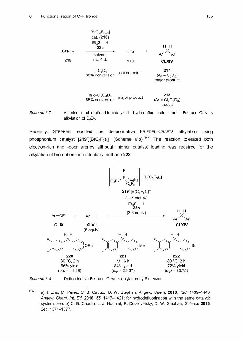
6 Functionalization of C–F Bonds 105
Scheme 6.7: Aluminum chlorofluoride-catalyzed hydrodefluorination and FRIEDEL–CRAFTS
alkylation of C6D6.
Recently, STEPHAN reported the defluorinative FRIEDEL–CRAFTS alkylation using
phosphonium catalyst [219+][B(C6F5)4]– (Scheme 6.8).[167] The reaction tolerated both
electron-rich and -poor arenes although higher catalyst loading was required for the
alkylation of bromobenzene into diarylmethane 222.
Scheme 6.8 : Defluorinative FRIEDEL–CRAFTS alkylation by STEPHAN.
[167]
a) J. Zhu, M. Pérez, C. B. Caputo, D. W. Stephan, Angew. Chem. 2016, 128, 1439–1443;
Angew. Chem. Int. Ed. 2016, 55, 1417–1421; for hydrodefluorination with the same catalytic
system, see: b) C. B. Caputo, L. J. Hounjet, R. Dobrovetsky, D. W. Stephan, Science 2013,
341, 1374–1377.

106 THEORETICAL PART II
6.2 Catalytic Generation of Alumenium Ions by Cooperative Al–H
Bond Activation in Defluorinative FRIEDEL–CRAFTS Alkylation
The ruthenium thiolate complex 25+ was previously applied to the cooperative activation of
dihydrogen, hydrosilanes 23, and hydroboranes 2 (Scheme 6.9). During the investigation of
carbon dioxide hydrosilylation, the complex 25+ was found to activate Al–H bonds (see
Chapter 5.6). In fact, the reaction with DIBAL–H (9b) was found to give full conversion at
room temperature in 30 min while the corresponding hydrosilylation of carbon dioxide
needed more than 2 days at 80 °C.
Scheme 6.9: Cooperative activation of dihydrogen, hydrosilanes, hydroboranes, and
hydroalanes.
Encouraged by the initial results in the carbon dioxide reduction, the cooperative activation
of DIBAL–H (9b) was further investigated. To test the potential of the proposed Al–H bond
activation, defluorination was chosen as a model reaction. The corresponding
hydrodefluorination of CF3-substituted anilines and indoles with hydrosilanes required high
catalyst loading, additional base, and elevated temperatures to reach full conversion.[72a]
Interestingly, the hydrodefluorination of trifluoroarene 225 led to exclusive formation of 226.
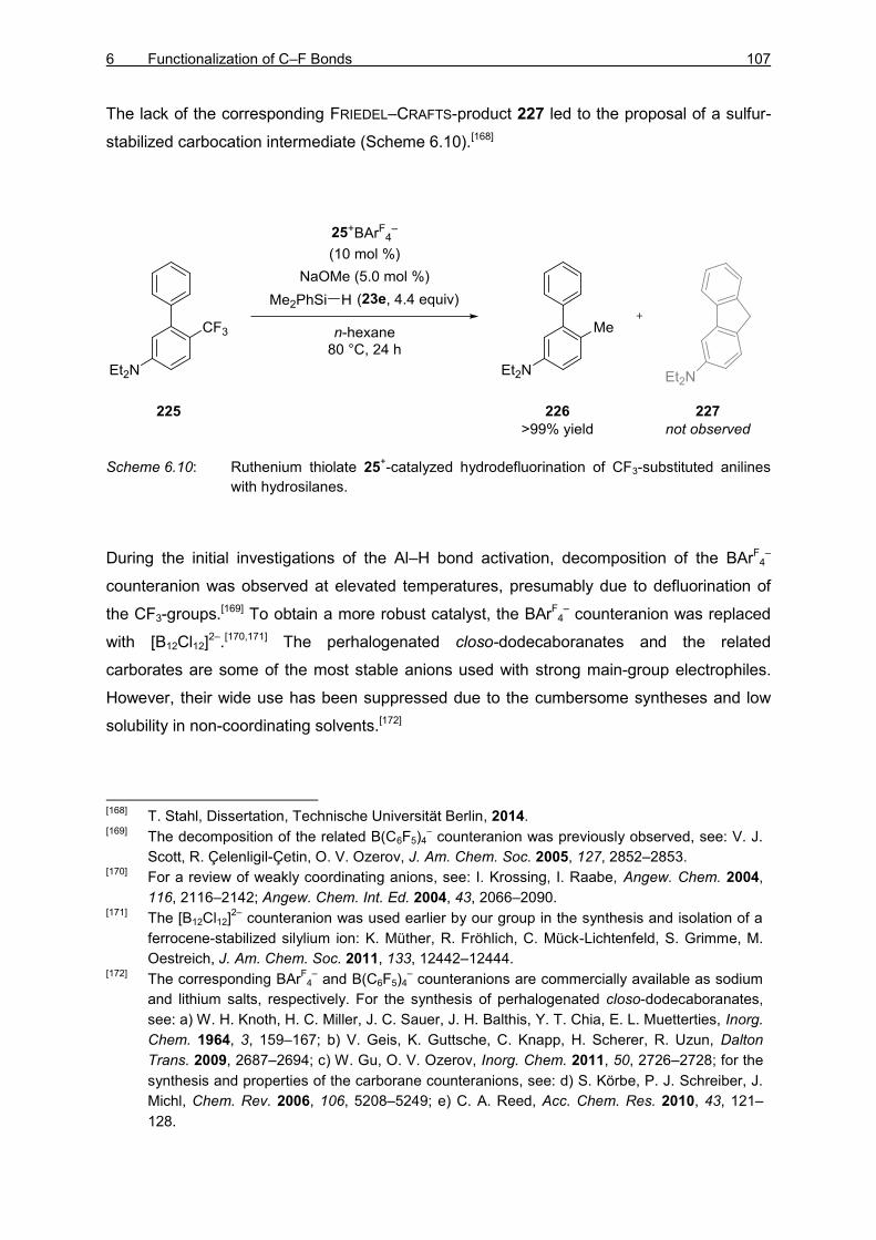
6 Functionalization of C–F Bonds 107
The lack of the corresponding FRIEDEL–CRAFTS-product 227 led to the proposal of a sulfur-
stabilized carbocation intermediate (Scheme 6.10).[168]
Scheme 6.10: Ruthenium thiolate 25+-catalyzed hydrodefluorination of CF3-substituted anilines
with hydrosilanes.
During the initial investigations of the Al–H bond activation, decomposition of the BArF4–
counteranion was observed at elevated temperatures, presumably due to defluorination of
the CF3-groups.[169] To obtain a more robust catalyst, the BArF4– counteranion was replaced
with [B12Cl12]2–.[170,171] The perhalogenated closo-dodecaboranates and the related
carborates are some of the most stable anions used with strong main-group electrophiles.
However, their wide use has been suppressed due to the cumbersome syntheses and low
solubility in non-coordinating solvents.[172]
[168]
T. Stahl, Dissertation, Technische Universität Berlin, 2014. [169]
The decomposition of the related B(C6F5)4– counteranion was previously observed, see: V. J.
Scott, R. Çelenligil-Çetin, O. V. Ozerov, J. Am. Chem. Soc. 2005, 127, 2852–2853. [170]
For a review of weakly coordinating anions, see: I. Krossing, I. Raabe, Angew. Chem. 2004,
116, 2116–2142; Angew. Chem. Int. Ed. 2004, 43, 2066–2090. [171]
The [B12Cl12]2–
counteranion was used earlier by our group in the synthesis and isolation of a
ferrocene-stabilized silylium ion: K. Müther, R. Fröhlich, C. Mück-Lichtenfeld, S. Grimme, M.
Oestreich, J. Am. Chem. Soc. 2011, 133, 12442–12444. [172]
The corresponding BArF
4– and B(C6F5)4
– counteranions are commercially available as sodium
and lithium salts, respectively. For the synthesis of perhalogenated closo-dodecaboranates,
see: a) W. H. Knoth, H. C. Miller, J. C. Sauer, J. H. Balthis, Y. T. Chia, E. L. Muetterties, Inorg.
Chem. 1964, 3, 159–167; b) V. Geis, K. Guttsche, C. Knapp, H. Scherer, R. Uzun, Dalton
Trans. 2009, 2687–2694; c) W. Gu, O. V. Ozerov, Inorg. Chem. 2011, 50, 2726–2728; for the
synthesis and properties of the carborane counteranions, see: d) S. Körbe, P. J. Schreiber, J.
Michl, Chem. Rev. 2006, 106, 5208–5249; e) C. A. Reed, Acc. Chem. Res. 2010, 43, 121–
128.

108 THEORETICAL PART II
The initial attempts to generate the cationic ruthenium thiolate [25g]2+[B12Cl12]
2– via chloride
abstraction using [Na2B12Cl12 · nH2O] analogous to the synthesis of [25g]+BArF4– either gave
no product (Table 6.1, entry 1) or led to decomposition (entry 2).[173,174] The reaction did not
proceed, probably due to poor solubility of the [Na2B12Cl12 · nH2O] in the weakly polar
solvents. On the other hand, the choice of the solvent was limited by the sensitivity of the
anticipated cationic ruthenium center 25+. During the previous investigations in our group,
we had observed that the hydrosilane adducts of the ruthenium thiolate 59+ are significantly
more soluble than 25+. Also, the formation of the hydrosilane adduct 48+ was expected to
trap the ruthenium as a cationic complex possibly preventing the equilibration back to the
ruthenium chloride 228g. Using a mixture of chlorobenzene and dimethylethylsilane (23i)
(ca. 9:1), the dissolution of [Na2B12Cl12 · nH2O] was observed within minutes accompanied
by gas evolution indicating dehydrogenative silylation of the trace moisture in
[Na2B12Cl12 · nH2O] into disiloxane 180i (entry 3). Simple filtration of sodium chloride and
careful evaporation of the volatiles afforded the cationic ruthenium complex [25g]2+[B12Cl12]
2–
in good yield.
Table 6.1: Synthesis of the ruthenium thiolate dodecaboranate complex [25g]2+[B12Cl12]
2–.
entry solvent temperature yield
1 benzene, toluene, CH2Cl2, PhCl,
PhF, o-Cl2C6H4, o-F2C6H4 r.t. no reaction
2 benzene, toluene, CH2Cl2, PhCl,
PhF, o-Cl2C6H4, o-F2C6H4 25 °C – 100 °C
low conversion,
decomposition
3 PhCl : Me2EtSi–H
(ratio ca. 9:1) r.t 92%
[173]
T. Stahl, unpublished results. [174]
The corresponding chloride abstraction with NaBArF
4 is usually completed within seconds.

6 Functionalization of C–F Bonds 109
Treatment of the complex [25g]2+[B12Cl12]
2– with DIBAL–H gave immediate conversion into a
new ruthenium-stereogenic complex [224g]2+[B12Cl12]
2–, reflected by six magnetically
inequivalent methyl groups, with a ruthenium hydride signal at –13.0 (d, J = 25.9 Hz) ppm in
the 1H NMR spectrum (Scheme 6.11).[175] Due to a strong, broad signal of the excess
DIBAL–H in the 27Al NMR spectrum, no new aluminium shift could be detected. Based on
analogous hydrosilane and hydroborane complexes, the new ruthenium complex was
assigned as the DIBAL–H adduct [224g]2+[B12Cl12]
2–. The lack of EXSY NMR signals
typically observed with the corresponding hydrosilane and hydroborane activation indicates
irreversibility of the activation.
Scheme 6.11: Cooperative activation of Al–H bonds (counteranion [B12Cl12]2–
omitted for clarity).
The catalytic activity of the complex [25g]2+[B12Cl12]
2– was investigated in the defluorination
of aromatic CF3-groups. The defluorination of trifluoroarene 229 proceeded smoothly at
60 °C in toluene (187). Instead of the expected hydrodefluorinated product 231,
defluorinated FRIEDEL–CRAFTS alkylation products 230 of toluene were observed with
p:o = 76:24 ratio of regioisomers (Table 6.2, entry 1). Lowering the toluene (187) loading to
10 equiv and adding fluorobenzene as solvent dropped the reaction time to 1.5 h (entry 2).
Further decreasing of the toluene (187) equivalence and increasing the concentration led to
slightly increased regioselectivity (entries 3 and 4). The reaction temperature could be
lowered to room temperature, and the catalyst loading to 1.25 mol % without affecting the
regioselectivity (entries 5 and 6). Other polar, electron-poor aromatic solvents could be used
as well but the regioselectivity was found to slightly decrease (entries 7–9). The reaction in
hexafluorobenzene did not give any product due to low solubility (entry 10).
[175]
The corresponding 1H NMR shift ranges for the hydrosilane and hydroborane adducts 59
+ and
26+
are –7.5/–8.3 and –8.1/–11.9 ppm, respectively.

110 THEORETICAL PART II
Table 6.2: Optimization of ruthenium thiolate complex [25g]2+[B12Cl12]
2–-catalyzed
defluorinative FRIEDEL–CRAFTS alkylation.
entry
catalyst
loading
(mol %)
toluene
(equiv) solvent
t
(h)
T
(°C)
conversion
(%)[a,b]
ratio
(o:p)[b,c]
1 2.5 50 - 24 60 99 24:76
2 2.5 10 PhF (0.08 M) 1.5 60 >99 22:78
3 2.5 5 PhF (0.08 M) 1.5 60 >99 24:76
4 2.5 5 PhF (0.4 M) 1.5 60 >99 19:81
5 2.5 5 PhF (0.4 M) 24 r.t. >99 19:81
6 1.25 5 PhF (0.4 M) 24 r.t. >99 19:81
7 2.5 5 1,2-F2C6H4 (0.4 M) 24 r.t. >99 21:79
8 2.5 5 PhCl (0.4 M) 24 r.t. >99 21:79
9 2.5 5 1,2-Cl2C6H4 (0.4 M) 24 r.t. >99 23:77
10 2.5 5 C6F6 (0.4 M) 24 r.t. 0 -
[a] Based on consumption of trifluoromethylarene 229 using tetracosane as internal standard.
[b]
Average of two runs. [c]
Determined by GLC analysis.
The optimized conditions were then employed in an initial screening of arene coupling
partners (Scheme 6.12). The alkylated toluene 230 was isolated in 40% yield with good
regioselectivity (p:o = 83:17). The reaction with o-xylene gave the product 232 in poor yield
(30%) but good regioselectivity (90:10). The alkylation of anisole proceeded smoothly
without ether cleavage, affording the diarylmethane 233 with 52% yield and excellent

6 Functionalization of C–F Bonds 111
regioselectivity (p:o = 95:5).[176] Although all reactions gave full conversion in the indicated
time and no significant side-products were observed by GLC analysis,[177] the isolated yields
were low. Since the formed products CLXV are more electron-rich and, hence, more reactive
under the reaction conditions, formation of oligomers is likely.
Scheme 6.12: Ruthenium thiolate complex [25g]2+[B12Cl12]
2–-catalyzed defluorinative FRIEDEL–
CRAFTS alkylation of toluene, o-xylene, and anisole.
The reaction is proposed to begin by cooperative activation of the Al–H bond 224+ (Scheme
6.13). The resulting formal alumenium ion 185+[178] abstracts a fluoride from the
trifluoromethyl arene CLIX giving aluminum fluoride 234[179] and the difluorocarbocation
CLXVI+.[180] The assumed reversible nucleophilic attack by the coupling arene CLXVII is
proposed to take place para (CLXVI+→CLXVIII+) or ortho (CLXVI+→CLXIX+).[181] The
selectivity of this step is not expected to explain the observed high selectivities. Instead, the
[176]
E. Winterfeldt, Synthesis 1975, 617–630. [177]
In the case of o-xylene, traces (<5%) of tert-butylation of o-xylene was observed. [178]
The liberation of free alumenium ion 185+ seems unlikely. The cation is assumed to be
stabilized by the thiolate sulfur atom or by the solvent. [179]
The formation of Al–F has been detected by 19
F NMR spectroscopy. [180]
The R–CF2+ carbocations are stabilized by backdonations from the fluorine atoms: a) G. A.
Olah, M. B. Comisarow, J. Am. Chem. Soc. 1969, 91, 2955–2961; b) K. O. Christe, X. Zhang,
R. Bau, J. Hegge, G. A. Olah, G. K. Surya Prakash, J. A. Sheehy, J. Am. Chem. Soc. 2000,
122, 481–487. [181]
The FRIEDEL–CRAFTS alkylation is known to be reversible. For early examples, see: N. O.
Calloway, Chem. Rev. 1935, 17, 327–392.
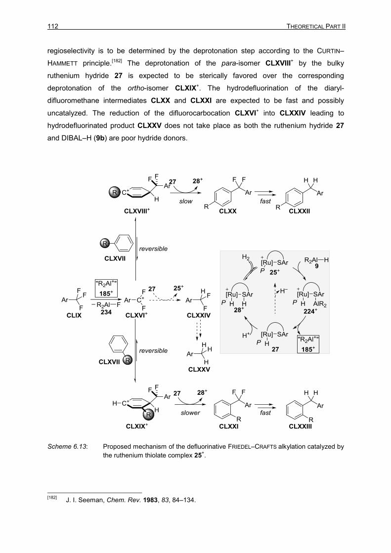
112 THEORETICAL PART II
regioselectivity is to be determined by the deprotonation step according to the CURTIN–
HAMMETT principle.[182] The deprotonation of the para-isomer CLXVIII+ by the bulky
ruthenium hydride 27 is expected to be sterically favored over the corresponding
deprotonation of the ortho-isomer CLXIX+. The hydrodefluorination of the diaryl-
difluoromethane intermediates CLXX and CLXXI are expected to be fast and possibly
uncatalyzed. The reduction of the difluorocarbocation CLXVI+ into CLXXIV leading to
hydrodefluorinated product CLXXV does not take place as both the ruthenium hydride 27
and DIBAL–H (9b) are poor hydride donors.
Scheme 6.13: Proposed mechanism of the defluorinative FRIEDEL–CRAFTS alkylation catalyzed by
the ruthenium thiolate complex 25+.
[182]
J. I. Seeman, Chem. Rev. 1983, 83, 84–134.
6 Functionalization of C–F Bonds 113
The catalytic activation of aluminum hydrides has not been widely explored yet, and the
ruthenium thiolate adduct of DIBAL–H 224g+ is the first example of a well-defined NMR-
spectroscopically characterized Al–H bond activation intermediate.
The cooperative Al–H bond activation by the ruthenium thiolate 25+ was utilized in
defluorination. The hydrodefluorination of CF3-substituted anilines and indoles with
hydrosilanes reported earlier[72a] required high catalyst loading and additional base.
Conversely the defluorination with DIBAL–H (9b) proceeds readily at room temperature with
catalyst loading of 1.25 mol % without additional base. Instead of hydrodefluorination of CF3-
groups into methyl groups, defluorinative FRIEDEL–CRAFTS alkylation of the electron-rich
solvent was obtained. The regioselectivity of the reaction is high due to the bulkiness of the
ruthenium hydride acting as a base.

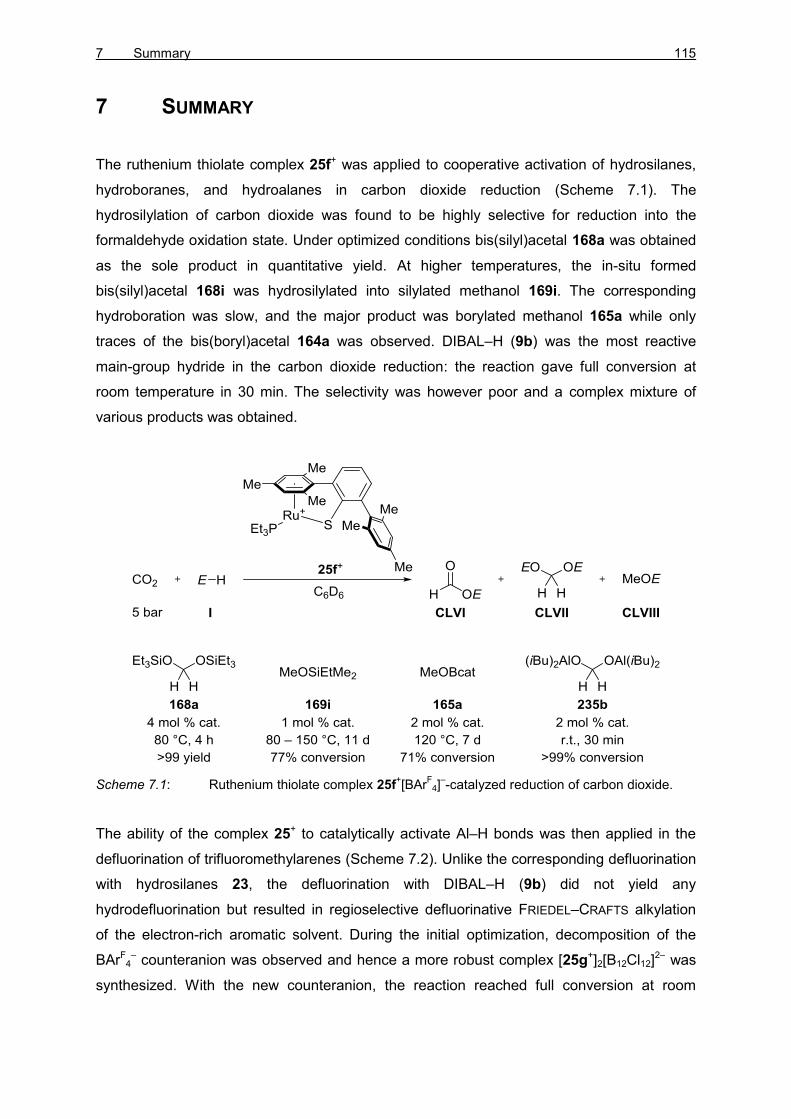
7 Summary 115
7 SUMMARY
The ruthenium thiolate complex 25f+ was applied to cooperative activation of hydrosilanes,
hydroboranes, and hydroalanes in carbon dioxide reduction (Scheme 7.1). The
hydrosilylation of carbon dioxide was found to be highly selective for reduction into the
formaldehyde oxidation state. Under optimized conditions bis(silyl)acetal 168a was obtained
as the sole product in quantitative yield. At higher temperatures, the in-situ formed
bis(silyl)acetal 168i was hydrosilylated into silylated methanol 169i. The corresponding
hydroboration was slow, and the major product was borylated methanol 165a while only
traces of the bis(boryl)acetal 164a was observed. DIBAL–H (9b) was the most reactive
main-group hydride in the carbon dioxide reduction: the reaction gave full conversion at
room temperature in 30 min. The selectivity was however poor and a complex mixture of
various products was obtained.
Scheme 7.1: Ruthenium thiolate complex 25f+[BAr
F4]
–-catalyzed reduction of carbon dioxide.
The ability of the complex 25+ to catalytically activate Al–H bonds was then applied in the
defluorination of trifluoromethylarenes (Scheme 7.2). Unlike the corresponding defluorination
with hydrosilanes 23, the defluorination with DIBAL–H (9b) did not yield any
hydrodefluorination but resulted in regioselective defluorinative FRIEDEL–CRAFTS alkylation
of the electron-rich aromatic solvent. During the initial optimization, decomposition of the
BArF4– counteranion was observed and hence a more robust complex [25g+]2[B12Cl12]
2– was
synthesized. With the new counteranion, the reaction reached full conversion at room

116 THEORETICAL PART II
temperature within 24 h. The DIBAL–H bond activation intermediate 224g+ was fully
characterized by NMR spectroscopy.
Scheme 7.2: Ruthenium thiolate complex [25g+]2[B12Cl12]
2–-catalyzed defluorinative FRIEDEL–
CRAFTS alkylation.
EXPERIMENTAL PART


1 General Information 119
1 GENERAL INFORMATION
All reactions were performed under argon or nitrogen atmosphere in flame-dried glassware.
For general cleaning, all laboratory glassware was kept overnight in an i-PrOH/KOH bath,
rinsed with distilled water, neutralized with saturated citric acid bath, rinsed again with
distilled water, and dried overnight at 120 °C. The glassware contaminated with transition
metals was initially rinsed with aqua regia (conc. HCl and conc. HNO3 in a ratio of 3:1) prior
to further cleaning. For the addition of reagents and solvents through silicon/rubber septa,
argon- or nitrogen-flushed disposable syringes and needles were used. All glass syringes
and stainless steel needles were used several times and stored at 120 °C. Solids were
added in a countercurrent of inert atmosphere or in solution. Low-temperature reactions
were either cooled by an ice bath, acetone/dry ice bath, or by using cryostats EK90 from
Haake or TC100E-F from Huber.
Physical Data
Melting Points (m.p.) were determined using a melting-point-determination apparatus from
Thompson Scientific and Stuart. The values are not corrected.
Boiling Points (b.p.) were measured at the distillation head and are not corrected.
Distillation under reduced pressure was determined directly by the connected pressure
gauge (VAP 5, from Vacuumbrand).
Chromatography
Qualitative thin-layer chromatography (TLC) was performed on glass plates with silica gel
60 F254 from Merck KGaA.
Following methods were used for indication of the analyte:
Exposure of the TLC plate to UV light (λ = 254 nm), UV absorption by the analyte.
Dipping the TLC plate into a solution of KMnO4 (3.0 g), K2CO3 (20 g), and KOH
(0.30 g) in distilled H2O (300 mL) and then heating with a heat gun.
Flash Chromatography was performed with silica gel from Merck of the grain size
40-63 µm, 230-400 mesh, ASTM.
Analytical gas-liquid chromatography (GLC) of the reaction mixtures and pure substances
were performed using gas chromatograph of the type 7890A from Agilent Technologies
[equipped with a fused silica capillary column of the type HP-5 capillary column (Length:

120 EXPERIMENTAL PART
30 m; inner diameter: 0.32 mm; film thickness of the covalently bonded stationary phase:
0.25 µm)].
All GLC analyses were performed using the following program:
Carrier gas N2; injector temperature 250 °C; detector temperature 300 °C; flow rate
1.7 mL/min; temperature program: starting temperature 40 °C, heating rate
10 °C/min, final temperature 280 °C for 10 min.
Qualitative analysis by high-performance liquid chromatography (HPLC) were performed
on an analytical HPLC system Series 1200 from Agilent Techonologies. The following
columns were used as a chiral stationary phase:
Daicel Chiralcel OD-H. OJ-H (normal phase)
Daicel Chiralpak IB (normal phase)
Daicel Chiralcel OJ-RH, OD-RH (reversed-phase)
NMR Spectroscopy
1H, 2H, 11B, 13C, 19F, 27Al 29Si, and 31P NMR spectra were recorded in CDCl3 (Eurisotop),
C6D6 (Eurisotop), CD2Cl2 (Sigma-Aldrich), o-Cl2C6D4 (Eurisotop) or toluene-d8. (Eurisotop) on
AV 400, AV 500, and AV 700 instruments from Bruker at Institut für Chemie, Technische
Universität Berlin. The 1H and 13C chemical shifts are reported in parts per million (ppm)
referenced to the residual solvent resonance as the internal standard (CHCl3: δ = 7.26 ppm
for 1H and CDCl3: δ = 77.16 ppm for 13C; C6D5H: δ = 7.16 ppm for 1H and C6D6: δ =
128.1 ppm for 13C; CDHCl2: δ = 5.32 ppm for 1H and CD2Cl2: δ = 53.84 ppm for 13C;
o-Cl2C6D3H: δ = 6.94 and 7.19 ppm for 1H and o-Cl2C6D4: δ = 127.2, 130.0, and 132.4 ppm
for 13C; toluene-d7: δ = 2.08, 6.67. 7.01, 7.09 ppm for 1H and toluene-d8: δ = 20.43, 125.13,
127.96, 128.87, 137.48 ppm).[183] For all other nuclei, the NMR resonance signals were
internally calibrated using the standardized scale for chemical shifts (unified chemical shift
scale).[184] Data are reported as follows: chemical shift, multiplicity (br s = broad singlet,
s = singlet, d = doublet, t = triplet, q = quartet, sept = septet, m = multiplet, and
mc = centrosymmetric multiplet), coupling constant, integration, and assignment. The
assignment of signals refers to the numbering of the structures in the figures and is in
accordance with careful interpretations made from 2D NMR spectroscopy. The term ”Ar”
refers to unspecified protons or carbon atoms of an aromatic system. Air- and moisture-
[183]
a) H. E. Gottlieb, V. Kotlyar, A. Nudelman, J. Org. Chem. 1997, 62, 7512–7515; b) G. R.
Fulmer, A. J. M. Miller, N. H. Sherden, H. E. Gottlieb, A. Nudelman, B. M. Stolz, J. E. Bercaw,
K. I. Goldberg, Organometallics 2010, 29, 2176–2179. [184]
R. K. Harris, E. D. Becker, S. M. C. de Menezes, R. Goodfellow, P, Granger, Pure Appl.
Chem. 2001, 73, 1795–1818.

1 General Information 121
sensitive samples were measured in J. YOUNG NMR tubes, the carbon dioxide reductions
were performed in Norell® Intermediate Pressure Valved NMR tubes, all other samples were
measured in reusable oven-dried standard NMR tubes. For more precise integration of 1H
NMR spectra in the in-situ monitored carbon dioxide reduction, the relaxation delay was set
to 15 sec.
Mass Spectrometry
High Resolution Mass Spectrometry (HRMS) measurements were performed at the
analytical facilities of the Institut für Chemie, Technische Universität Berlin with an LTQ
Orbitrap XL [atmospheric-pressure chemical ionization (APCI) or electrospray ionization
(ESI)] or with a Finnigan MAT 95S (electron ionization, 70 eV) from Thermo Scientific. The
in-detail fragmentation was omitted and only the molecular ion peak or characteristic
molecular fragments are considered.
Low Resolution Mass Spectrometry (LRMS) data were measured with the GC-MS-system
5975C from Agilent Technologies by electron ionization (EI). The GLC is equipped with a
fused silica capillary column of the type HP-5MS capillary column (Length: 30 m; inner
diameter: 0.25 mm; film thickness of the covalently bonded stationary phase: 0.25 µm)].
Analyses were typically performed using the following program:
Carrier gas He; injector temperature 300 °C; detector temperature 300 °C; flow rate
0.8 mL/min; temperature program: starting temperature 40 °C, heating rate
10 °C/min, final temperature 280 °C for 10 min.
Infrared Spectroscopy
Infrared (IR) spectra were recorded on a Cary 630 FT-IR from Agilent Techologies equipped
with an ATR unit and are reported (br = broad, w = weak, m, medium, s = strong) in
wavenumbers (cm−1).
Optical Rotation
The optical rotations were determined with a Polatronic H532 polarimeter from
Schmidt+Haensch. The analytes were measured as a solution in the reported solvent in
1 dm cuvettes, and the specific rotation was calculated using the following formula:
[α]λT =
[α] × 100
c × d

122 EXPERIMENTAL PART
Where ”λ” is the wavelength (nm), ”T” is the measurement temperature (°C), [α] is the
polarimeter-determined rotation, ”c” is the concentration (g/100 mL) and ”d” is the length of
the cuvette (dm). The sodium D-line (λ = 589 nm) is used as the light source.
X-Ray Crystal Structural Analysis
Data sets for X-ray crystal structure analyses were collected by PAULA NIXDORF on a Nonius
KappaCCD circle diffractometer equipped with Cu-Kα-radiation (λ = 154.178 pm) graphite
monochromator in the analytical facility at the Institut für Chemie, Technische Universität
Berlin and analyzed by Dr. ELISABETH IRRAN. Thermal ellipsoids are shown at the 50%
probability level; R-values are given for the observed reflections, wR2-values are given for all
reflections.
Software
GC-data were recorded and analyzed using EZChrom Elite Compact by Agilent. NMR data
was recorded and analyzed using Topspin 3.2 by Bruker. The stacked NMR spectra were
generated using GIMP 2.8.4 image manipulation program. GC-MS data was measured and
analyzed using Enhanced ChemStation 02.02.1431 by Agilent Technologies. The HRMS
data was analyzed using Mass++ 2.4.0 by Shimadzu and Eisai Co., Ltd. IR data was
recorded and analyzed using Microlab and Agilent Resolutions Pro 5.2.0 by Agilent
Technologies. X-ray structures and DFT calculated structures were analyzed using Mercury
3.1.1 by CCDC. 3D graphics were generated using CYLview 1.0b.[185] All schemes in this
thesis were drawn in ChemDraw Professional 15.0.0.106 by PerkinElmer. The referencis
were retrieved using Chemistry Reference Resolver.[186] The thesis is written using Microsoft
Office 2010 by Microsoft.
Solvents and Reagents
Dichloromethane (CH2Cl2) and n-pentane were heated at reflux over CaH2 and distilled under
nitrogen atmosphere. Tetrahydrofuran (THF) and diethyl ether (Et2O) were heated at reflux
over potassium with benzophenone as indicator and distilled under nitrogen atmosphere.
Toluene was heated at reflux over sodium with benzophenone as indicator and distilled
under nitrogen atmosphere. Technical grade ethanol and acetone were used without further
purification unless stated otherwise. For extraction and flash chromatography, technical
grade solvents (tert-butyl methyl ether, cyclohexane, n-pentane, dichloromethane, diethyl
ether, and ethyl acetate) were distilled prior to use. Solvents with high purity standard were
[185]
CYLview, 1.0b; Legault, C. Y., Université de Sherbrooke, 2009. [186]
http://chemsearch.kovsky.net/
1 General Information 123
used for the high-performance liquid chromatography (HPLC): n-heptane (Roth, Merck-
Schuchardt and Aldrich), i-PrOH (Roth and Aldrich), acetonitrile (Roth and Aldrich) and water
(Aldrich). All solvents and liquid reagents used in a glovebox were distilled and degassed by
the freeze-pump-thaw method.

124 EXPERIMENTAL PART
The following reagents were used in this thesis:
Reagent Supplier
Acetophenone Fluka
Acetophenone-d3 Sigma-Aldrich
Carbon dioxide, >99.95% Air Liquide
Carbon dioxide, 18 ± 1.8% in argon Air Liquide
Chlorotriethylsilane, Et3SiCl Alfa Aesar
Bis(1,5-cyclooctadiene)diiridium(I) dichloride Acros, STREM
Diisobutylaluminiumium hydride, DIBAL−H Sigma-Aldrich
Diisobutylaluminiumium hydride (in n-hexane) In-house stock
Di-tert-butylchlorophosphine Alfa Aesar
Di-n-butyl ether ABCR
Dimethylaminopyridine, DMAP Sigma-Aldrich
Hydrogen Air Liquide
Magnesium In-house stock
4-Methoxyacetophenone Sigma-Aldrich
Methyl iodide-d3 Sigma-Aldrich
Tris(pentafluorophenyl)borane, B(C6F5)3 Dr. D. HOG
(S)-1-Phenylethanol BASF
Triphenylmethylium tetrakis(pentafluorophenyl)borate Dr. A. SIMONNEAU, V. ROHDE
Potassium-tert-butoxide, KOt-Bu Dr. L. DELVOS
Resorcinol Acros
Sodium closo-dodecachlorododecaboranate, Na2B12Cl12 Dr. K. MÜTHER, J. MOHR
Sodium hydride In-house stock
Triethylamine, Et3N In-house stock
4-(Trifluoromethyl)acetophenone Sigma-Aldrich
4-(Trifluoromethyl)biphenyl Dr. A. SIMONNEAU
Triphenylphosphite Sigma-Aldrich

1 General Information 125
Literature Known Compounds
The following compounds were prepared and characterized according to literature-known
procedures:
[(Et3P)Ru(SDmp)]BArF4 (25f+[BArF
4]–),[30] [(iPr3P)Ru(SDmp)Cl] 228g,[73,168]
[(iPr3P)Ru(SDmp)]BArF4 (25g+[BArF
4]–),[73,168] [({p-FC6H4}3P)Ru(SDmp)]BArF
4
(25h+[BArF4]
–),[72a] (SiS)-1-isopropyl-1-silatetraline [(SiS)-23b],[187] (SiS)-isopropylmethyl-
phenylsilane [(SiS)-23c],[188] deuterium-labeled dimethylphenylsilane (23e-d1).189
Enantiopure Silicon-Stereogenic Hydrosilanes
Scheme 1.1: Preparation of enantiopure silicon-stereogenic hydrosilanes.
The racemic silicon-stereogenic hydrosilanes 23b and 23c as well as the silyl menthol ethers
236 and 237 were synthesized according to literature procedures.[73a,188] After the Si–O
coupling reaction, the crude products were initially purified by flash chromatography
(15 7 cm, 100 mL, cyclohexane:tert-butyl methyl ether 95:5). The obtained crude products
contained [(SiS)-236 and (SiR)-236] or [(SiS)-237 and (SiR)-237] as 50:50 mixture of
diastereomers (Rf ca. 0.2) with traces of menthol 238 or 8-phenylmenthol 239 (Rf ca. 0.05)
as an impurity. The separation of diastereomers was achieved with repeated flash
chromatography (20 10 cm, 5 L, cyclohexane). Typically the first flash chromatography
affords three fractions: one with d.r. = 2:1, one with d.r. = 1:1, and one with d.r. = 1:2. To
[187]
S. Rendler, PhD thesis, Westfälische Wilhelms-Universität Münster, 2007. [188]
a) ref. [73a]; b) H. F. T. Klare, PhD thesis, Westfälische Wilhelms-Universität Münster, 2011. [189]
M. Yan, T. Jin, Y. Ishikawa, T. Minato, T. Fujita, L.-Y. Chen, M. Bao, N. Asao, M.-W. Chen, Y.
Yamamoto, J. Am. Chem. Soc. 2012, 134, 17536–17542.

126 EXPERIMENTAL PART
achieve d.r. > 20:1, at least three rounds of flash chromatography were usually required.[190]
The higly enantioenriched hydrosilanes 23b and 23c were released by reductive Si–O
cleavage according to literature procedures.
The separation of the diastereomers could not be followed by TLC or GLC analysis as the
diastereomers have identical retention times. Instead, the d.r. of each fraction was
determined by 1H NMR analysis of small aliquots by integration of the following characteristic
signals.
Table 1.1: Characteristic 1H NMR signals of silyl menthol ethers.
silyl menthol ether Rf
(cyclohexane)
1H NMR (400 MHz, CDCl3), δ(ppm)
(SiS)-236
0.21 0.49 (d, 3J10’,8’ = 6.9 Hz, 3H, H-10’)
(SiR)-236
0.18 0.58 (d, 3J10’,8’ = 7.0 Hz, 3H, H-10’)
(SiS)-237
0.24 0.38 (s, 3H, Si-CH3)
(SiR)-237
0.20 0.35 (s, 3H, Si-CH3)
[190]
The cyclohexane consumption required to do this can be decreased significantly by recycling
the cyclohexane from the collected fractions back to the column. This way a flash column with
total volume of fractions over 100 L can be operated using less than 10 L of solvent.

1 General Information 127
Nomenclature and Numbering
The numbering of compounds was done analogous to their representative structural drawing
and does not correspond to the IUPAC recommendations.


2 General Procedures 129
2 GENERAL PROCEDURES
2.1 General Procedure for the Hydrosilylation of Ketones Catalyzed
by Brookhart’s Iridium(III) Pincer Complex 73+ (GP1)
According to a procedure reported by Brookhart and co-workers,[79a] iridium(III) pincer
complex 73+[B(C6F5)4]– (3.4 mg, 2.5 µmol, 0.50 mol %) was dissolved in chlorobenzene
(0.15 mL). The hydrosilane (0.50 mmol, 1.0 equiv or 2.0 mmol, 4.0 equiv) was added
dropwise, and the resulting mixture was stirred for 5 min at room temperature. The ketone
(60 mg, 0.50 mmol, 1.0 equiv) was added, and the solution was stirred in a glovebox for the
indicated time. After complete conversion (GLC monitoring), the reaction mixture was
removed from the glovebox and quenched with one drop of Et3N. Purification by flash
column chromatography on silica gel using n-pentane/diethyl ether mixtures (100:0→90:10)
as eluent afforded the analytically pure silylether 111 and recovered hydrosilane 23,
respectively.
2.2 General Procedure for the Reductive Si–O Bond Cleavage of
Silyl Ethers (GP 2)
A SCHLENK tube equipped with a magnetic stirring bar and a reflux condenser was charged
with a solution of the silyl ether (0.20 mmol, 1.0 equiv) in n-heptane (2.0 mL). DIBAL−H (9b,
0.80 mL, 0.80 mmol, 4.0 equiv, 1.0M in n-hexane) was added in one portion at room
temperature, and the resulting reaction mixture was heated to reflux and maintained at this
temperature for 20 h. The reaction mixture was allowed to cool to room temperature and
quenched by careful addition of 1M aqueous HCl (20 mL). The organic layer was separated,
and the aqueous phase was extracted with tert-butyl methyl ether (3 × 15 mL). The
combined organic layers were washed with brine (10 mL), dried over Na2SO4, filtered, and
the volatiles were evaporated under reduced pressure. The crude product was purified by
flash column chromatography on silica gel using n-pentane/diethyl ether mixtures
(100:0→90:10) as eluent, affording the analytically pure hydrosilane and alcohol.
130 EXPERIMENTAL PART
2.3 General Procedure for the Stoichiometric Reaction of Iron(0)
Complex 124 with Hydrosilanes 23 (GP 3)
Iron(0) complex 124[191] (44.5 mg, 50.0 µmol, 1.00 equiv) was weighed into a SCHLENK flask
with a magnetic stir bar. The hydrosilane (0.15 mmol, 3.0 equiv) was weighed in a vial,
dissolved in 2.0 mL of toluene (0.5 mL of C6D6 for NMR studies), and added into the
SCHLENK flask. The reaction mixture was heated in an oil bath at 70 °C changing the color
from dark purple to dark red. The time for completion (100% conversion by NMR
spectroscopy) varied depending on the hydrosilane used: (EtO)3SiH (23f) 12 h, Me2PhSiH
(23e) 6 days, and MePh2SiH (23g) reached 90% conversion after 6 days. The reaction
mixture was concentrated, and the product was obtained as a crude red oil. The crude
product was dissolved in benzene, frozen, and the solvent was sublimated in vacuo to afford
the desired product as a red powder.
2.4 Carbon Dioxide Reduction (GP 4)
In a glove box, a medium walled valved NMR tube was charged with main-group hydride
reagent (0.080 mmol, 1.0 equiv), Ru−S complex 25+[B(C6F5)4]– (1.6 or 3.2 µmol, 2.0 or
4.0 mol %), toluene (ca. 8 mg), and C6D6 (0.4 mL). The NMR tube was sealed and a 1H
NMR spectrum was measured to obtain an accurate calibration of the internal standard. The
tube was pressurized at room temperature with carbon dioxide (>99.95%, 5 bar, ca. 2 mmol,
ca. 25 equiv) and heated to 80 °C. The reaction was monitored with 1H NMR using the
toluene signals as internal standard.
2.5 Ruthenium Thiolate-Catalyzed Defluorinative FRIEDEL–CRAFTS
Alkylation (GP 5)
In a 5-mL vial in a glovebox, the trifluoromethyl-substituted arene (229, 1.0 equiv), complex
[25g]+2[B12Cl12]2– (2.5 mol %), and arene (5.0 equiv) were dissolved in the indicated solvent
(0.4 M). The solution was mixed and DIBAL−H (9b, neat, 4.0 equiv) was added. The reaction
was monitored by GLC analysis of aliquots (for the optimization studies, tetracosane was
used as internal standard). After full conversion, the vial was removed from the glovebox, the
reaction was quenched by the addition of cyclohexane:EtOH (95:5), transferred to a flask
[191]
a) ref [115]; b) D. Gallego, PhD thesis, Technische Universität Berlin, 2015.

2 General Procedures 131
containing silica gel, and concentrated in vacuo. The crude product was purified by flash
chromatography using cyclohexane:toluene (95:5) as eluent.


3 Description of Experiments 133
3 DESCRIPTION OF EXPERIMENTS
3.1 Mechanistic Investigations
3.1.1 Iridium(III) POCOP Pincer Complex-Catalyzed Carbonyl Hydrosilylation
3.1.1.1 Synthesis of the Cationic Pincer Complex (73+[B(C6F5)4]–)
3.1.1.1.1 [(POCOP)Ir(H)(Cl)] (240)
Oil-free NaH (96 mg, 4.0 mmol, 3.3 equiv) was suspended in THF (20 mL) in a 100-mL
SCHLENK flask. Resorcinol (210 mg, 1.9 mmol, 1.6 equiv) as a solution in THF (20 mL) was
added dropwise (H2 evolution). After complete addition, the reaction mixture was heated at
reflux for 1 h. A solution of di-tert-butylchlorophosphine (0.76 mL, 720 mg, 4.0 mmol,
3.3 equiv) in THF (10 mL) was added dropwise and the mixture was refluxed for 1 h. The
solvent was removed in vacuo, the residue was extracted with n-pentane (80 mL), filtered
through a pad of Celite®, and concentrated in vacuo (50 °C, 15 h). The resulting clear
viscous oil was combined with bis(1,5-cyclooctadiene)diiridium(I) dichloride (400 mg,
0.60 mmol, 0.5 equiv) and dissolved in toluene (5 mL). The mixture was heated at reflux for
3 d. The solvent was removed in vacuo, and the residue was extracted with n-pentane (ca.
3 mL) with sonication (2 15 min). The red solid was filtered, washed with n-pentane, and
dried in vacuo to afford pincer complex 240 (647 mg, 1.03 mmol, 86%) as a red solid.
1H NMR (500 MHz, CD2Cl2): δ = –41.39 (t, 2JH,P = 13.4 Hz, 1H, Ir–H), 1.32–1.38 (m, 36H, H-
6), 6.53 (d, 3J3,4 = 8.0 Hz, 2H, H-3), 6.76 (t, 3J4,3 = 8.0 Hz, 1H, H-4) ppm.
31P NMR (202 MHz, CD2Cl2): δ = 175.3 ppm.
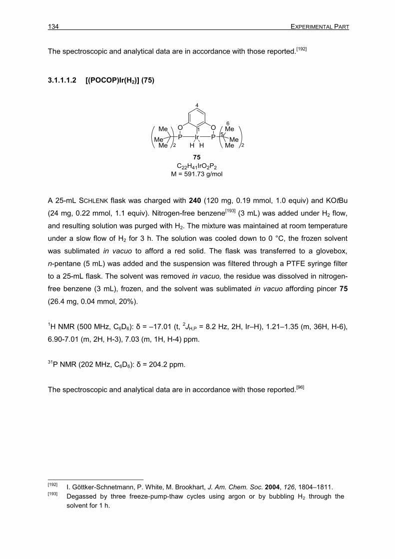
134 EXPERIMENTAL PART
The spectroscopic and analytical data are in accordance with those reported.[192]
3.1.1.1.2 [(POCOP)Ir(H2)] (75)
A 25-mL SCHLENK flask was charged with 240 (120 mg, 0.19 mmol, 1.0 equiv) and KOtBu
(24 mg, 0.22 mmol, 1.1 equiv). Nitrogen-free benzene[193] (3 mL) was added under H2 flow,
and resulting solution was purged with H2. The mixture was maintained at room temperature
under a slow flow of H2 for 3 h. The solution was cooled down to 0 °C, the frozen solvent
was sublimated in vacuo to afford a red solid. The flask was transferred to a glovebox,
n-pentane (5 mL) was added and the suspension was filtered through a PTFE syringe filter
to a 25-mL flask. The solvent was removed in vacuo, the residue was dissolved in nitrogen-
free benzene (3 mL), frozen, and the solvent was sublimated in vacuo affording pincer 75
(26.4 mg, 0.04 mmol, 20%).
1H NMR (500 MHz, C6D6): δ = –17.01 (t, 2JH,P = 8.2 Hz, 2H, Ir–H), 1.21–1.35 (m, 36H, H-6),
6.90-7.01 (m, 2H, H-3), 7.03 (m, 1H, H-4) ppm.
31P NMR (202 MHz, C6D6): δ = 204.2 ppm.
The spectroscopic and analytical data are in accordance with those reported.[96]
[192]
I. Göttker-Schnetmann, P. White, M. Brookhart, J. Am. Chem. Soc. 2004, 126, 1804–1811. [193]
Degassed by three freeze-pump-thaw cycles using argon or by bubbling H2 through the
solvent for 1 h.

3 Description of Experiments 135
3.1.1.1.3 [(POCOP)IrH(acetone)]+[B(C6F5)4]– [73]+[B(C6F5)4]
–
A 10-mL SCHLENK tube was charged with 75 (35 mg, 59 µmol, 1.0 equiv) and
Ph3C+[B(C6F5)4]
– (48 mg, 85 µmol, 1.4 equiv). Freshly distilled nitrogen-free acetone (1 mL)
was added, and the mixture was stirred for 2 h. The solvent was evaporated in vacuo, and
the dark orange solid was again dissolved in acetone (0.5 mL). n-Pentane (2 mL) was added
to precipitate a dark orange solid. The solvents were removed via syringe, and the
recrystallization was repeated, affording pincer [73]+[B(C6F5)4]– as an orange solid (26 mg,
19 µmol, 33%).
1H NMR (500 MHz, o-Cl2C6D4): δ = –42.25 (t, 2JH,P = 11.6 Hz, 1H, Ir–H), 1.07 (s, 36H, H-6),
1.95 (s, 6H, H-2’), 6.55–6.68 (m, 2H, H-3), 6.79–6.88 (m, 1H, H-4) ppm.
31P-NMR (202 MHz, o-Cl2C6D4): δ = 173.7 ppm.
The spectroscopic and analytical data are in accordance with those reported.[78]

136 EXPERIMENTAL PART
3.1.1.2 Stereochemical Course at the Silicon Atom of Silicon Stereogenic
Hydrosilanes in Hydrosilylation of Acetophenone Catalyzed by
[73]+[B(C6F5)4]−
3.1.1.2.1 1-Isopropyl-1-(1-phenylethoxy)-1-silatetraline (111b)
Using 1.0 equiv of hydrosilane (SiS)-23b:
Prepared from (SiS)-1-isopropyl-1-silatetraline [(SiS)-23b, 95 mg, 0.50 mmol, 1.0 equiv, [α]D20
= –58.8 (c = 0.34, CHCl3, e.r. = 97:3)] and acetophenone (109, 60 mg, 0.50 mmol, 1.0 equiv)
according to GP 1. The reaction mixture was stirred at room temperature under argon for
20 h. Purification by flash column chromatography on silica gel afforded the analytically pure
silyl ether 111b (130 mg, 0.43 mmol, 86%, d.r. = 55:45) as a colorless oil.
Using 4.0 equiv of hydrosilane (SiS)-23b:
Prepared from (SiS)-1-isopropyl-1-silatetraline [(SiS)-23b, 0.38 g, 2.0 mmol, 4.0 equiv, [α]D20 =
–58.8 (c = 0.34, CHCl3, e.r. = 97:3)] and acetophenone (109, 60 mg, 0.50 mmol, 1.0 equiv)
according to GP 1. The reaction mixture was stirred at room temperature under argon for
30 min. Purification by flash column chromatography on silica gel afforded the analytically
pure silyl ether 111b (130 mg, 0.43 mmol, 86%, d.r. = 55:45) and recovered hydrosilane
(SiS)-23b [270 mg, 1.4 mmol, 95%, [α]D20 = –64.5 (c = 0.48, CHCl3, e.r. = 94:6)] as colorless
oils.
Rf = 0.08 (cyclohexane).

3 Description of Experiments 137
GLC: tR = 21.4 min [(SiS,S)- and (SiR,R)-111b], tR = 21.3 min [(SiS,R)- and (SiR,S)-111b].
IR (ATR): /cm–1 = 3268 (w), 3054 (w), 2920 (s), 2860 (s), 1683 (m), 1589 (m), 1434 (s),
1366 (m), 1267 (m), 1086 (s), 1029 (s), 955 (s), 880 (m), 738 (s), 695 (s).
HRMS (APCI) for C20H27OSi [(M+H)+]: calculated 311.1826, found 311.1824.
NMR spectroscopic data for (SiS,S)- and (SiR,R)-111b (major diastereomer)
1H NMR (500 MHz, CDCl3): δ = 0.66 (dddd, J = 15.1 Hz, J = 7.9 Hz, J = 4.3 Hz, J = 0.9 Hz,
1H, H-1A), 0.77 (ddd, J = 15.1 Hz, J = 10.4 Hz, J = 4.8 Hz, 1H, H-1B), 0.91–1.17 (m, 7H, H-
1’’, H-2’’), 1.34 (d, 3J1’,2’ = 6.4 Hz, 3H, H-1’), 1.63–1.71 (m, 1H, H-2A), 1.82–1.90 (m, 1H, H-
2B), 2.61 (ddd, J = 15.9 Hz, J = 9.7 Hz, J = 2.8 Hz, 1H, H-3A), 2.70 (ddd, J = 15.9 Hz, J =
7.6 Hz, J = 2.4 Hz, 1H, H-3B), 4.76 (q, 3J2’,1’ = 6.4 Hz, 1H, H-2’), 7.05–7.11 (m, 1H, H-Ar),
7.16–7.32 (m, 7H, H-Ar), 7.62–7.64 (m, 1H, H-Ar) ppm.
13C{1H} NMR (126 MHz, CDCl3): δ = 9.8 (C-1), 14.2 (C-1’’), 17.1 (2’’A), 17.2 (2’’B), 23.1 (C-
2), 27.1 (C-1’), 35.5 (C-3), 71.1 (C-2’), 125.45 (C-7), 125.46 (C-4’), 126.9 (C-6’), 128.2 (C-5’),
128.6 (C-5), 129.6 (C-6), 132.2 (C-9), 134.7 (C-8), 146.8 (C-3’), 150.4 (C-4) ppm.
29Si DEPT NMR (99 MHz, CDCl3): δ = 0.1 ppm.
NMR spectroscopic data for (SiS,R)- and (SiR,S)-111b (minor diastereomer)
1H NMR (500 MHz, CDCl3): δ = 0.91–1.17 (m, 9H, H-1A, H-1B, H-1’’, H-2’’), 1.39 (d, 3J1’,2’ =
6.3 Hz, 3H, H-1’), 1.82–1.90 (m, 1H, H-2A), 1.96–2.03 (m, 1H, H-2B), 2.66 (ddd, J = 16.4
Hz, J = 6.2 Hz, J = 3.0 Hz, 1H, H-3A), 2.70 (ddd, J = 15.8 Hz, J = 7.5 Hz, J = 2.5 Hz, 1H, H-
3B), 4.83 (q, 3J2’,1’ = 6.4 Hz, 1H, H-2’), 7.03–7.10 (m, 2H, H-Ar), 7.16–7.32 (m, 6H, H-Ar),
7.34–7.35 (m, 1H, H-Ar) ppm.
13C{1H} NMR (126 MHz, CDCl3): δ = 10.5 (C-1), 14.1 (C-1’’), 17.1 (2’’A), 17.3 (2’’B), 23.1 (C-
2), 27.2 (C-1’), 35.6 (C-3), 71.2 (C-2'), 125.2 (C-7), 125.37 (C-4’), 126.8 (C-6’), 128.1 (C-5’),
128.6 (C-5), 129.5 (C-6), 131.6 (C-9), 134.8 (C-8), 146.6 (C-3’), 150.1 (C-4) ppm.
29Si DEPT NMR (99 MHz, CDCl3): δ = 0.0 ppm.
~

138 EXPERIMENTAL PART
The spectroscopic and analytical data are in accordance with those reported.[101c]
3.1.1.2.2 Isopropylmethylphenyl(1-phenylethoxy)silane (111c)
Using 1.0 equiv of hydrosilane (SiS)-23c:
Prepared from (SiS)-isopropylmethylphenylsilane [(SiS)-23c, 75 mg, 0.46 mmol, 1.0 equiv,
[α]D20 = –5.0 (c = 0.28, CHCl3, e.r. = 97:3)] and acetophenone (109, 56 mg, 0.47 mmol,
1.0 equiv) according to GP 1. The reaction mixture was stirred at room temperature under
argon for 20 h. Purification by flash column chromatography on silica gel afforded the
analytically pure silyl ether 111c (120 mg, 0.41 mmol, 90%, d.r. = 59:41) as a colorless oil.
Using 4.0 equiv of hydrosilane (SiS)-23c:
Prepared from (SiS)-isopropylmethylphenylsilane [(SiS)-23c, 0.33 g, 2.0 mmol, 4.0 equiv,
[α]D20 = –5.0 (c = 0.28, CHCl3, e.r. = 97:3)] and acetophenone (109, 60 mg, 0.50 mmol,
1.0 equiv) according to GP 1. The reaction mixture was stirred at room temperature under
argon for 30 min. Purification by flash column chromatography on silica gel afforded the
analytically pure silylether 111c (130 mg, 0.45 mmol, 89%, d.r. = 62:38) and recovered
hydrosilane (SiS)-23c [210 mg, 1.3 mmol, 85%, [α]D20 = –4.1 (c = 0.80, CHCl3, e.r. = 74:26)]
as colorless oils.
Rf = 0.09 (cyclohexane).
IR (ATR): /cm–1 = 3066 (w), 3025 (w), 2954 (m), 2863 (m), 1450 (m), 1427 (m), 1367 (m),
1252 (m), 1112 (s), 1089 (s), 1031 (m), 996 (m), 957 (s), 882 (m), 735 (s), 698 (s).
~

3 Description of Experiments 139
GLC: tR = 18.7 min [(SiS,S)- and (SiR,R)-111c], tR = 18.6 min [(SiS,R)- and (SiR,S)-111c].
HRMS (APCI) for C18H25OSi [(M+H)+]: calculated 285.1669, found 285.1666.
NMR spectroscopic data for (SiS,R)- and (SiR,S)-111c (major diastereomer)
1H NMR (500 MHz, CDCl3): δ = 0.20 (s, 3H, Si-CH3), 0.90 (d, 3J2’’,H-1’’ = 7.1 Hz, 3H, H-2’’A),
1.01 (d, 3J2’’,H-1’’ = 7.0 Hz, 3H, H-2’’B), 1.03–1.13 (m, 1H, H-1’’), 1.42 (d, 3J2’,1’ = 6.4 Hz, 3H,
H-1’), 4.85 (q, 3J2’,1’ = 6.3 Hz, 1H, H-2’), 7.20–7.24 (m, 1H, H-6’), 7.28–7.34 (m, 4H, H-4’,H-
5’), 7.36–7.41 (m, 3H, H-3,H-4), 7.58–7.60 (m, 2H, H-2) ppm.
13C{1H} NMR (126 MHz, CDCl3): δ = –6.0 (Si-CH3), 14.5 (C-2’’A), 17.0 (C-2’’B, C-1’), 27.3
(C-1’’), 71.3 (C-2’), 125.5 (C-4’), 127.0 (C-6’), 127.8 (C-3), 128.3 (C-5’), 129.6 (C-4), 134.3
(C-2), 136.9 (C-1), 146.8 (C-3’) ppm.
29Si DEPT NMR (99 MHz, CDCl3): δ = 7.3 ppm.
NMR spectroscopic data for (SiS,S)- and (SiR,R)-111c (minor diastereomer)
1H NMR (500 MHz, CDCl3): δ = 0.35 (s, 3H, Si-CH3), 0.97 (d, 3J2’’,1’’ = 7.2 Hz, 3H, H-2’’A),
1.00 (d, 3J2’’,1’’ = 7.1 Hz, 3H, H-2’’B), 1.03–1.13 (m, 1H, H-1’’), 1.43 (d, 3J1’,2’ = 6.3 Hz, 3H, H-
1’), 4.89 (q, 3J2’,1’ = 6.4 Hz, 1H, H-2’), 7.20–7.24 (m, 1H, H-6’), 7.28–7.34 (m, 4H, H-4’,H-5’),
7.36–7.41 (m, 3H, H-3, H-4), 7.46–7.48 (m, 2H, H-2) ppm.
13C{1H} NMR (125 MHz, CDCl3): δ = –5.2 (Si-CH3), 14.4 (C-2’’A), 17.2 (C-2’’B, C-1’), 27.2
(C-1’’), 71.3 (C-2’), 125.5 (C-4’), 126.9 (C-6’), 127.7 (C-3), 128.2 (C-5’), 129.5 (C-4), 134.3
(C-2), 136.5 (C-1), 146.6 (C-3’) ppm.
29Si DEPT NMR (100 MHz, CDCl3): δ = 7.0 ppm.
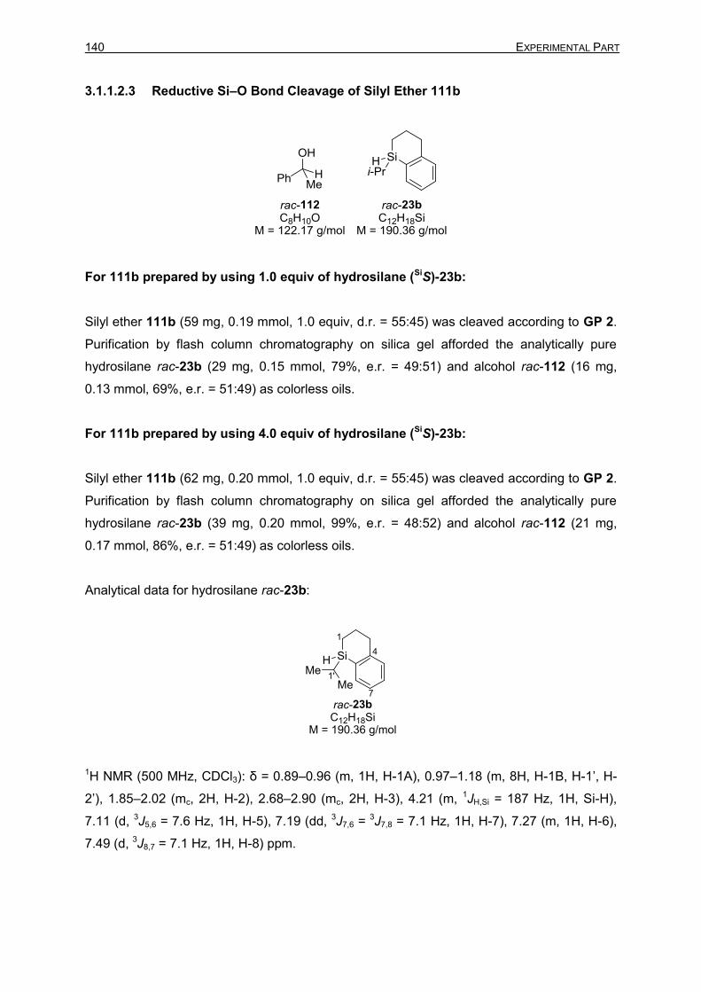
140 EXPERIMENTAL PART
3.1.1.2.3 Reductive Si–O Bond Cleavage of Silyl Ether 111b
For 111b prepared by using 1.0 equiv of hydrosilane (SiS)-23b:
Silyl ether 111b (59 mg, 0.19 mmol, 1.0 equiv, d.r. = 55:45) was cleaved according to GP 2.
Purification by flash column chromatography on silica gel afforded the analytically pure
hydrosilane rac-23b (29 mg, 0.15 mmol, 79%, e.r. = 49:51) and alcohol rac-112 (16 mg,
0.13 mmol, 69%, e.r. = 51:49) as colorless oils.
For 111b prepared by using 4.0 equiv of hydrosilane (SiS)-23b:
Silyl ether 111b (62 mg, 0.20 mmol, 1.0 equiv, d.r. = 55:45) was cleaved according to GP 2.
Purification by flash column chromatography on silica gel afforded the analytically pure
hydrosilane rac-23b (39 mg, 0.20 mmol, 99%, e.r. = 48:52) and alcohol rac-112 (21 mg,
0.17 mmol, 86%, e.r. = 51:49) as colorless oils.
Analytical data for hydrosilane rac-23b:
1H NMR (500 MHz, CDCl3): δ = 0.89–0.96 (m, 1H, H-1A), 0.97–1.18 (m, 8H, H-1B, H-1’, H-
2’), 1.85–2.02 (mc, 2H, H-2), 2.68–2.90 (mc, 2H, H-3), 4.21 (m, 1JH,Si = 187 Hz, 1H, Si-H),
7.11 (d, 3J5,6 = 7.6 Hz, 1H, H-5), 7.19 (dd, 3J7,6 = 3J7,8 = 7.1 Hz, 1H, H-7), 7.27 (m, 1H, H-6),
7.49 (d, 3J8,7 = 7.1 Hz, 1H, H-8) ppm.

3 Description of Experiments 141
13C{1H} (126 MHz, CDCl3): δ = 6.3 (C-1), 12.5 (C-1’), 18.2 (C-2’A), 18.4 (C-2’B), 22.9 (C-2),
35.4 (C-3), 125.4 (C-7), 128.9 (C-5), 129.2 (C-6), 130.7 (C-9), 135.7 (C-8), 149.7 (C-4) ppm.
29Si DEPT NMR (99 MHz, CDCl3): δ = –17.4 ppm.
HRMS (APCI) for C12H18Si [M+]: calculated 190.1172, found 190.1164.
HPLC (Daicel Chiralcel OJ-RH, 20 °C, MeCN:H2O 50:50, flow rate 0.5 mL min–1, λ =
210 nm): tR = 50.7 min [(SiR)-23b], 52.5 min [(SiS)-23b].
Analytical data for alcohol rac-112:
1H NMR (500 MHz, CDCl3): δ = 1.39 (d, 3J1,2 = 6.5 Hz, 3H, H-1), 1.69 (br s, 1H, O–H), 4.79
(q, 3J2,1 = 6.5 Hz, 1H, H-2), 7.14–7.19 (m, 1H, H-6), 7.21–7.29 (m, 4H, H-4, H-5) ppm.
13C{1H} NMR (126 MHz, CDCl3): δ = 25.3 (C-1), 70.6 (C-2), 125.5 (C-4), 127.6 (C-6), 128.7
(C-5), 146.0 (C-3) ppm.
HRMS (APCI) for C8H10ONa [(M+Na)+]: calculated 145.0624, found 145.0654.
HPLC (Daicel Chiralpak IB, 20 °C, n-heptane:iPrOH 95:5, flow rate 0.8 mL min–1, λ =
210 nm): tR = 8.8 min [(R)-112], 9.6 min [(S)-112].
The spectroscopic and analytical data are in accordance with those reported.[194]
[194]
S. Rendler, M. Oestreich, C. P. Butts, G. C. Lloyd-Jones, J. Am. Chem. Soc. 2007, 129, 502–
503.

142 EXPERIMENTAL PART
3.1.1.2.4 Reductive Si–O Bond Cleavage of Silyl Ether 111c
For 111c prepared by using 1.0 equiv of hydrosilane (SiS)-23c:
Silyl ether 111c (62 mg, 0.22 mmol, 1.0 equiv, d.r. = 56:44) was cleaved according to GP 2.
Purification by flash column chromatography on silica gel afforded the analytically pure
hydrosilane rac-23c (31 mg, 0.19 mmol, 85%, e.r. = 48:52) and alcohol rac-112 (28 mg,
0.22 mmol, 99%, e.r. = 49:51) as colorless oils.
For 111c prepared by using 4.0 equiv of hydrosilane (SiS)-23c:
Silyl ether 111c (54 mg, 0.19 mmol, 1.0 equiv, d.r. = 56:44) was cleaved according to GP 2.
Purification by flash column chromatography on silica gel afforded the analytically pure
enantioenriched hydrosilane (SiR)-23c [27 mg, 0.17 mmol, 86%, e.r. = 36:64, [α]D20 = 6.7
(c = 0.23, CHCl3)] and alcohol rac-112 (22 mg, 0.18 mmol, 93%, e.r. = 46:54) as colorless
oils.
Analytical data for hydrosilane 23c:
1H NMR (500 MHz, CDCl3): δ = 0.33 (d, 3JSi-CH3,Si-H = 3.8 Hz, 3H, Si-CH3), 1.00–1.04 (m, 6H,
H-2’), 1.05–1.13 (m, 1H, H-1’), 4.27 (qd, 3JSi-H,Si-CH3 = 3.7 Hz, 3JSi-H,1’ = 2.5 Hz, 1JH,Si = 186 Hz,
1H, Si-H), 7.33–7.39 (m, 3H, H-3, H-4), 7.51–7.56 (m, 2H, H-2) ppm.
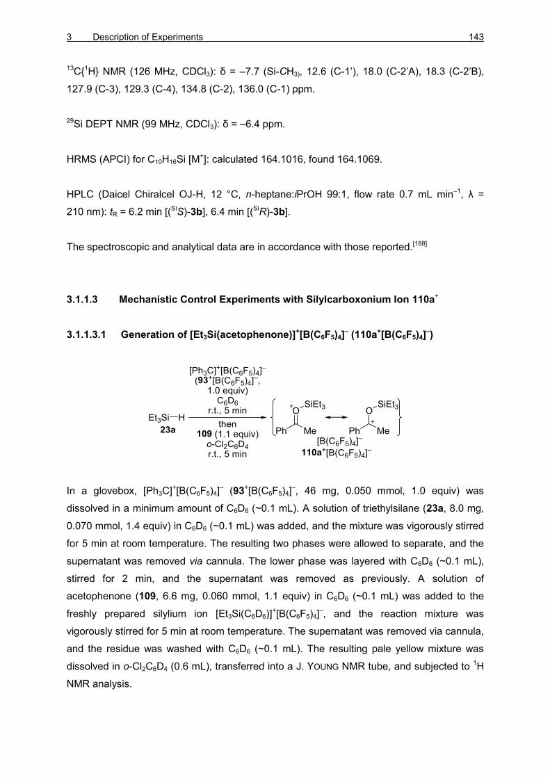
3 Description of Experiments 143
13C{1H} NMR (126 MHz, CDCl3): δ = –7.7 (Si-CH3), 12.6 (C-1’), 18.0 (C-2’A), 18.3 (C-2’B),
127.9 (C-3), 129.3 (C-4), 134.8 (C-2), 136.0 (C-1) ppm.
29Si DEPT NMR (99 MHz, CDCl3): δ = –6.4 ppm.
HRMS (APCI) for C10H16Si [M+]: calculated 164.1016, found 164.1069.
HPLC (Daicel Chiralcel OJ-H, 12 °C, n-heptane:iPrOH 99:1, flow rate 0.7 mL min–1, λ =
210 nm): tR = 6.2 min [(SiS)-3b], 6.4 min [(SiR)-3b].
The spectroscopic and analytical data are in accordance with those reported.[188]
3.1.1.3 Mechanistic Control Experiments with Silylcarboxonium Ion 110a+
3.1.1.3.1 Generation of [Et3Si(acetophenone)]+[B(C6F5)4]– (110a+[B(C6F5)4]
–)
In a glovebox, [Ph3C]+[B(C6F5)4]– (93+[B(C6F5)4]
–, 46 mg, 0.050 mmol, 1.0 equiv) was
dissolved in a minimum amount of C6D6 (~0.1 mL). A solution of triethylsilane (23a, 8.0 mg,
0.070 mmol, 1.4 equiv) in C6D6 (~0.1 mL) was added, and the mixture was vigorously stirred
for 5 min at room temperature. The resulting two phases were allowed to separate, and the
supernatant was removed via cannula. The lower phase was layered with C6D6 (~0.1 mL),
stirred for 2 min, and the supernatant was removed as previously. A solution of
acetophenone (109, 6.6 mg, 0.060 mmol, 1.1 equiv) in C6D6 (~0.1 mL) was added to the
freshly prepared silylium ion [Et3Si(C6D6)]+[B(C6F5)4]
–, and the reaction mixture was
vigorously stirred for 5 min at room temperature. The supernatant was removed via cannula,
and the residue was washed with C6D6 (~0.1 mL). The resulting pale yellow mixture was
dissolved in o-Cl2C6D4 (0.6 mL), transferred into a J. YOUNG NMR tube, and subjected to 1H
NMR analysis.

144 EXPERIMENTAL PART
The spectroscopic data are in accordance with those reported.[188b]
3.1.1.3.2 Control Experiment A: Addition of Iridium Dihydride 75 to
Silylcarboxonium Ion 110a+
Iridium dihydride 75 (15 mg, 0.025 mmol, 0.50 equiv) was added to a freshly prepared
solution of [Et3Si(acetophenone)]+[B(C6F5)4]– (110a+, 0.050 mmol, 1.0 equiv) in o-Cl2C6D4
(0.6 mL) at room temperature. The resulting mixture was immediately subjected to 1H NMR
analysis. A mixture of 110a+:113+:111a (53:44:3) along with 74a+ was detected.
3.1.1.3.3 Control Experiment B: Addition of Triethylsilane (23a) to Silylcarboxonium
Ion 110a+ and Iridium Dihydride 75
Triethylsilane (23a, 8 mg, 0.07 mmol, 1 equiv) was added to the solution obtained in
3.1.1.3.2, and the resulting mixture was immediately subjected to 1H NMR analysis. A
mixture of 111a and 114a (50:50) was detected.

3 Description of Experiments 145
3.1.1.3.4 Control Experiments C
3.1.1.3.4.1 Addition of Acetophenone (109) to Silylcarboxonium Ion 110a+ and Iridium
Dihydride 75
Acetophenone (109, 12 mg, 0.10 mmol, 2.0 equiv) was added to the solution obtained in
3.1.1.3.2, and the resulting mixture was immediately subjected to 1H NMR analysis. No
reaction was detected.
3.1.1.3.4.2 Addition of Triethylsilane (23a) to Silylcarboxonium Ion 110a+, Iridium
Dihydride 75, and Acetophenone (109)
Triethylsilane (23a, 20 mg, 0.17 mmol, 3.4 equiv) was added to the solution obtained in
3.1.1.3.4.1, and the resulting mixture was immediately subjected to 1H NMR analysis.
Initially, a mixture of 110a+:111a:114a:115 (16:42:5:37) was obtained. After 10 min, only the
formation of ethyl benzene (115) along with decomposition was observed.
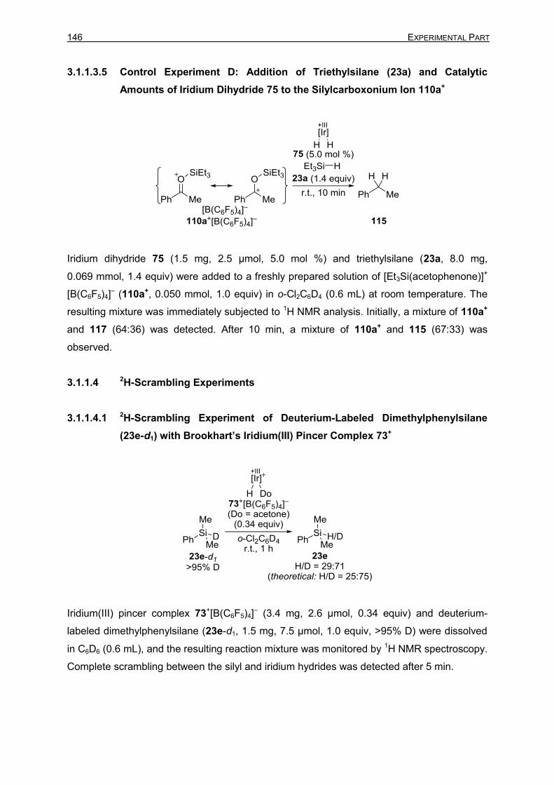
146 EXPERIMENTAL PART
3.1.1.3.5 Control Experiment D: Addition of Triethylsilane (23a) and Catalytic
Amounts of Iridium Dihydride 75 to the Silylcarboxonium Ion 110a+
Iridium dihydride 75 (1.5 mg, 2.5 µmol, 5.0 mol %) and triethylsilane (23a, 8.0 mg,
0.069 mmol, 1.4 equiv) were added to a freshly prepared solution of [Et3Si(acetophenone)]+
[B(C6F5)4]– (110a+, 0.050 mmol, 1.0 equiv) in o-Cl2C6D4 (0.6 mL) at room temperature. The
resulting mixture was immediately subjected to 1H NMR analysis. Initially, a mixture of 110a+
and 117 (64:36) was detected. After 10 min, a mixture of 110a+ and 115 (67:33) was
observed.
3.1.1.4 2H-Scrambling Experiments
3.1.1.4.1 2H-Scrambling Experiment of Deuterium-Labeled Dimethylphenylsilane
(23e-d1) with Brookhart’s Iridium(III) Pincer Complex 73+
Iridium(III) pincer complex 73+[B(C6F5)4]– (3.4 mg, 2.6 µmol, 0.34 equiv) and deuterium-
labeled dimethylphenylsilane (23e-d1, 1.5 mg, 7.5 µmol, 1.0 equiv, >95% D) were dissolved
in C6D6 (0.6 mL), and the resulting reaction mixture was monitored by 1H NMR spectroscopy.
Complete scrambling between the silyl and iridium hydrides was detected after 5 min.

3 Description of Experiments 147
3.1.1.4.2 2H-Scrambling Experiment of Deuterium-Labeled Dimethylphenylsilane
(23e-d1) with Iridium Dihydride 75
Iridium dihydride 75 (1.7 mg, 2.9 µmol, 0.39 equiv) and deuterium-labeled
dimethylphenylsilane (23e-d1, 1.5 mg, 7.5 µmol, 1.0 equiv, >95% D) were dissolved in C6D6
(0.6 mL), and the resulting reaction mixture was monitored by 1H NMR spectroscopy.
Complete scrambling between the silyl and iridium hydrides was detected after 2 h.
3.1.1.4.3 2H-Scrambling Experiment of Deuterium-Labeled Acetophenone (109-d3)
with Brookhart’s Iridium(III) Pincer Complex 73+: Synthesis of
Triethyl(phenyl-trideuteromethyl-methoxy)silane (109-d3)
Prepared from acetophenone-d3 [109-d3, 61 mg, 0.50 mmol, 1.0 equiv, >95% D] and
triethylsilane (23a, 170 mg, 1.5 mmol, 3.0 equiv) according to GP 1. The reaction mixture
was stirred at room temperature under argon for 30 min. Purification by flash column
chromatography on silica gel afforded the analytically pure silylether 111a-d3 (120 mg,
0.49 mmol, 99%, >95% D) as a colorless oil.
Rf = 0.10 (cyclohexane).
GLC (SE-54): tR = 14.0 min.
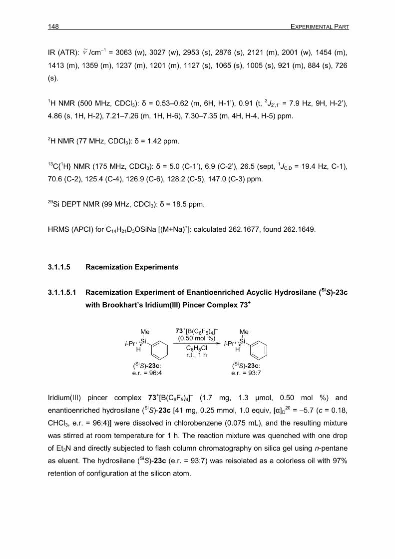
148 EXPERIMENTAL PART
IR (ATR): /cm–1 = 3063 (w), 3027 (w), 2953 (s), 2876 (s), 2121 (m), 2001 (w), 1454 (m),
1413 (m), 1359 (m), 1237 (m), 1201 (m), 1127 (s), 1065 (s), 1005 (s), 921 (m), 884 (s), 726
(s).
1H NMR (500 MHz, CDCl3): δ = 0.53–0.62 (m, 6H, H-1’), 0.91 (t, 3J2’,1’ = 7.9 Hz, 9H, H-2’),
4.86 (s, 1H, H-2), 7.21–7.26 (m, 1H, H-6), 7.30–7.35 (m, 4H, H-4, H-5) ppm.
2H NMR (77 MHz, CDCl3): δ = 1.42 ppm.
13C{1H} NMR (175 MHz, CDCl3): δ = 5.0 (C-1’), 6.9 (C-2’), 26.5 (sept, 1JC,D = 19.4 Hz, C-1),
70.6 (C-2), 125.4 (C-4), 126.9 (C-6), 128.2 (C-5), 147.0 (C-3) ppm.
29Si DEPT NMR (99 MHz, CDCl3): δ = 18.5 ppm.
HRMS (APCI) for C14H21D3OSiNa [(M+Na)+]: calculated 262.1677, found 262.1649.
3.1.1.5 Racemization Experiments
3.1.1.5.1 Racemization Experiment of Enantioenriched Acyclic Hydrosilane (SiS)-23c
with Brookhart’s Iridium(III) Pincer Complex 73+
Iridium(III) pincer complex 73+[B(C6F5)4]– (1.7 mg, 1.3 µmol, 0.50 mol %) and
enantioenriched hydrosilane (SiS)-23c [41 mg, 0.25 mmol, 1.0 equiv, [α]D20 = –5.7 (c = 0.18,
CHCl3, e.r. = 96:4)] were dissolved in chlorobenzene (0.075 mL), and the resulting mixture
was stirred at room temperature for 1 h. The reaction mixture was quenched with one drop
of Et3N and directly subjected to flash column chromatography on silica gel using n-pentane
as eluent. The hydrosilane (SiS)-23c (e.r. = 93:7) was reisolated as a colorless oil with 97%
retention of configuration at the silicon atom.
~

3 Description of Experiments 149
3.1.1.5.2 Racemization Experiment of Enantioenriched Acyclic Hydrosilane (SiS)-23c
with Iridium Dihydride 75
Iridium dihydride 75 (0.8 mg, 1 µmol, 0.5 mol %) and enantioenriched hydrosilane (SiS)-23c
[41 mg, 0.25 mmol, 1.0 equiv, [α]D20 = –5.7 (c = 0.18, CHCl3, e.r. = 96:4)] were dissolved in
chlorobenzene (0.075 mL), and the resulting mixture was stirred at room temperature for 1 h.
The reaction mixture was quenched with one drop of Et3N and directly subjected to flash
column chromatography on silica gel using n-pentane as eluent. The hydroilane (SiS)-23c
(e.r. = 95:5) was reisolated as a colorless oil with 99% retention of configuration at the silicon
atom.
3.1.1.5.3 Racemization Experiment of Enantioenriched Silyl Ether (S)-111a with
Brookhart’s Iridium(III) Pincer Complex 73+
3.1.1.5.3.1 Preparation of Enantioenriched (S)-Triethyl(1-phenylethoxy)silane [(S)-
111a]
(S)-1-Phenylethanol [(S)-112, 120 mg, 1.0 mmol, 1.0 equiv, e.r. > 99:1], Et3N (110 mg,
1.1 mmol, 1.1 equiv), and DMAP (6 mg, 0.05 mmol, 0.05 equiv) were dissolved in CH2Cl2
(5 mL). Et3SiCl (160 mg, 1.05 mmol, 1.05 equiv) was added dropwise, and the resulting
mixture was stirred at room temperature for 16 h. The crude mixture was concentrated under
reduced pressure, extracted with n-pentane (3 × 10 mL), and filtered through a plug of
Celite®. Purification by flash column chromatography on silica gel using cyclohexane:ethyl

150 EXPERIMENTAL PART
acetate (95:5) as eluent afforded the analytically pure silyl ether (S)-111a (220 mg, 0.94
mmol, 94%, e.r. > 99:1) as a colorless oil.
Rf = 0.10 (cyclohexane).
[α]D20 = –74.5 (c = 0.11, CHCl3, e.r. > 99:1)
GLC (SE-54): tR = 14.0 min.
IR (ATR): /cm–1 = 2925 (s), 2875 (m), 1690 (w), 1449 (m), 1237 (m), 1367 (m), 1413 (m),
1092 (s), 1003 (m), 954 (m), 792 (m), 724 (s).
1H NMR (500 MHz, CDCl3): δ = 0.49–0.62 (m, 6H, H-1’), 0.91 (t, 3J2’,1’ = 7.9 Hz, 9H, H-2’),
1.43 (d, 3J1,2 = 6.4 Hz, 3H, H-1), 4.86 (q, 3J2,1 = 6.4 Hz, 1H, H-2), 7.20–7.24 (m, 1H, H-6),
7.28–7.35 (m, 4H, H-4, H-5) ppm.
13C{1H} NMR (126 MHz, CDCl3): δ = 5.0 (C-1’), 6.9 (C-2’), 27.4 (C-1), 70.7 (C-2), 125.4 (C-
4), 126.9 (C-6), 128.2 (C-5), 147.1 (C-3) ppm.
29Si DEPT NMR (99 MHz, CDCl3): δ = 18.5 ppm.
HRMS (APCI) for C14H24OSiNa [(M+Na)+]: calculated 259.1489, found 259.1436.
HPLC (Daicel Chiracel OJ-RH, 20 °C, MeCN:H2O 70:30, flow rate 0.4 mL min–1, λ =
210 nm): tR = 17.5 min [(S)-111a], 19.5 min [(R)-111a].
The spectroscopic and analytical data are in accordance with those reported.[195]
[195]
a) L. D. Field, B. A. Messerle, M. Rehr, L. P. Soler, T. W. Hambley, Organometallics 2003, 22,
2387–2395; b) M. Mewald, Ph.D. Thesis, Westfälische Wilhelms-Universität Munster, 2012.
~
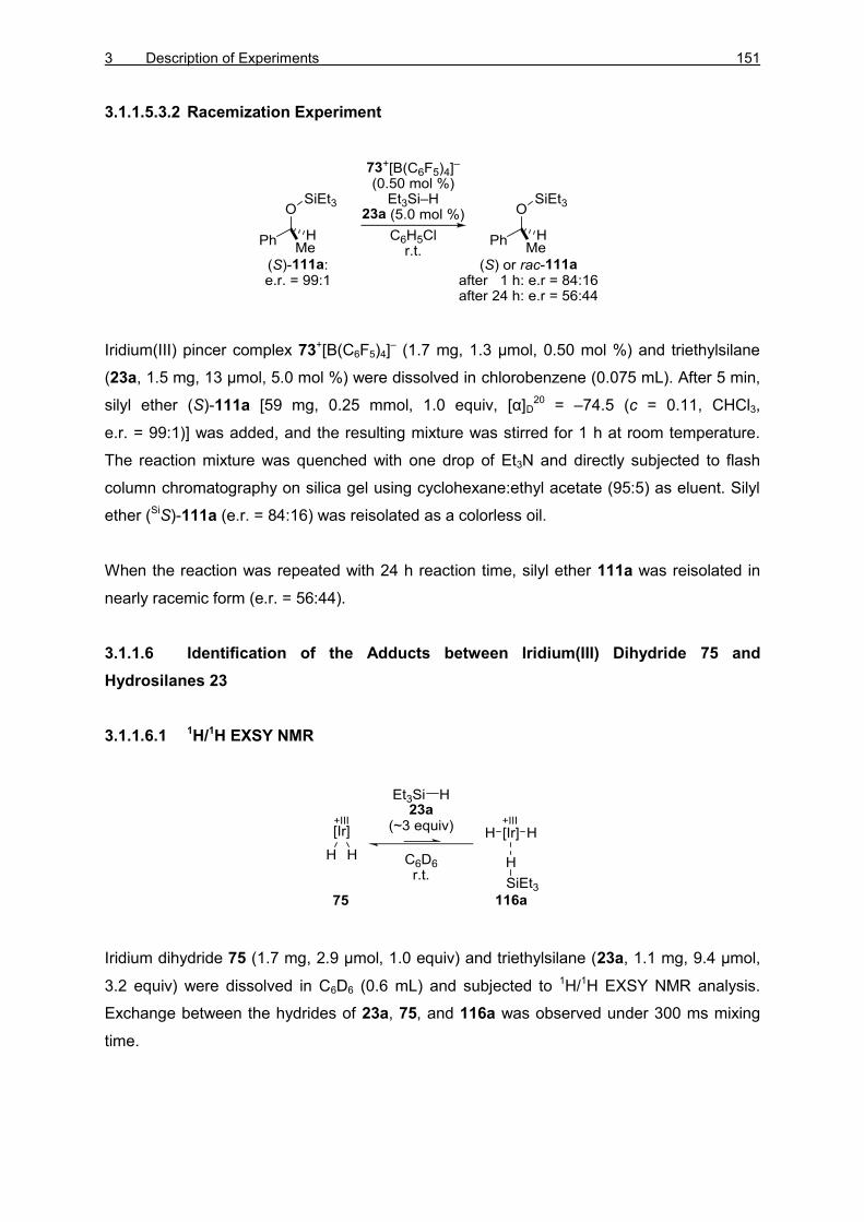
3 Description of Experiments 151
3.1.1.5.3.2 Racemization Experiment
Iridium(III) pincer complex 73+[B(C6F5)4]– (1.7 mg, 1.3 µmol, 0.50 mol %) and triethylsilane
(23a, 1.5 mg, 13 µmol, 5.0 mol %) were dissolved in chlorobenzene (0.075 mL). After 5 min,
silyl ether (S)-111a [59 mg, 0.25 mmol, 1.0 equiv, [α]D20 = –74.5 (c = 0.11, CHCl3,
e.r. = 99:1)] was added, and the resulting mixture was stirred for 1 h at room temperature.
The reaction mixture was quenched with one drop of Et3N and directly subjected to flash
column chromatography on silica gel using cyclohexane:ethyl acetate (95:5) as eluent. Silyl
ether (SiS)-111a (e.r. = 84:16) was reisolated as a colorless oil.
When the reaction was repeated with 24 h reaction time, silyl ether 111a was reisolated in
nearly racemic form (e.r. = 56:44).
3.1.1.6 Identification of the Adducts between Iridium(III) Dihydride 75 and
Hydrosilanes 23
3.1.1.6.1 1H/1H EXSY NMR
Iridium dihydride 75 (1.7 mg, 2.9 µmol, 1.0 equiv) and triethylsilane (23a, 1.1 mg, 9.4 µmol,
3.2 equiv) were dissolved in C6D6 (0.6 mL) and subjected to 1H/1H EXSY NMR analysis.
Exchange between the hydrides of 23a, 75, and 116a was observed under 300 ms mixing
time.

152 EXPERIMENTAL PART
3.1.1.6.2 Variable-Temperature NMR
Iridium dihydride 75 (1.7 mg, 2.9 µmol, 1.0 equiv) and triethylsilane (23a, 1.0 mg, 8.4 µmol,
2.9 equiv) were dissolved in toluene-d8 (0.6 mL) and subjected to 1H NMR analysis. The
sample was then cooled stepwise to 197 K. Mixtures of 75, 116a, 117a, and 107a were
obtained (Table 3.1). NMR spectra at room temperature were identical before and after the
cooling.
Table 3.1: Ratios of 75, 116a, 117a, and 107a at varied temperatures in toluene-d8[a]
T (K) 75 (%) 116a (%) 117a (%) 107a (%)
300 98.8 1.2 <0.5 <0.5
277 97.3 2.0 <0.5 0.6
250 94.6 3.5 <0.5 1.9
224 91.8 4.4 0.9 2.9
197 80.1 6.1 9.9 3.9
[a] Ratios determined by integration of the hydride signals in the 1H NMR spectrum.
3.1.1.6.3 Crystallization Experiments
Iridium dihydride 75 (~ 2 mg) and the corresponding hydrosilane (23a or 23e, ~ 20 mg,
excess) were dissolved in benzene (0.5 mL). Slow evaporation (~1 week) under argon
atmosphere at room temperature led to release of dihydrogen and crystallization of single
crystals of 107a and 107e suitable for X-ray crystallography.

3 Description of Experiments 153
All attempts to obtain single crystals of 116 or 117 with various hydrosilanes were
unsuccessful. Subjection of crystals of 107 to an atmosphere of hydrogen led to deterioration
of the crystals.
3.1.1.6.4 Hydrogenation of Iridium Silyl Monohydride 107a
Iridium silyl hydride 107a (~5 mg) was dissolved in C6D6 (0.6 mL) and subjected to 1H NMR
analysis. The NMR tube was then flushed with H2 (5 s) and sealed. Immediate 1H NMR
analysis showed quantitative conversion of 107a into 116a.
Selected NMR data for 116a:
1H NMR (500 MHz, C6D6, 300 K): δ = –8.29 (br s, 3H, Ir–H) ppm.[196]
1H NMR (500 MHz, toluene-d8, 224 K): δ = –8.33 (t, 2JH,P = 9.0 Hz, 3H, Ir–H) ppm.
1H,13C HMBC (500 / 126 MHz, C6D6, 300 K): δ = 2.8 (C-1’), 8.4 (C-2’), 28.5 (C-6), 38.4 (C-5),
105.5 (C-3), 119.0 (C-4), 167.9 (C-2) ppm.
No signals were detected in 29Si NMR.
[196]
All three iridium hydrides coalesce into one signal.

154 EXPERIMENTAL PART
31P{1H} NMR (203 MHz, C6D6): δ = 183.2 (br s) ppm.
1H,31P HMQC NMR (500 / 203 MHz, toluene-d8, 300 K): δ(1H) = –8.35 ppm / δ(31P) = 182.7
ppm.
Selected NMR data for 117a:
1H NMR (500 MHz, toluene-d8, 197 K): δ = –9.31 (t, 2JH,P = 10.5 Hz, 3H, Ir–H) ppm.[196]
1H,29Si HMBC NMR (500 / 99 MHz, toluene-d8, 220 K): δ(1H) = –9.34 ppm / δ(29Si) = –0.7
ppm.
31P NMR (203 MHz, toluene-d8, 220 K): δ = 171.4 (m) ppm.
Selected NMR data for 107a:
1H NMR (500 MHz, C6D6, 300 K): δ = –15.81 (t, 2JH,P = 5.9 Hz, 1H, Ir–H) ppm.

3 Description of Experiments 155
1H,29Si HMBC NMR (500 / 99 MHz, toluene-d8, 220 K): δ(1H) = –15.83 ppm / δ(29Si) = –3.9
ppm.
31P{1H} NMR (203 MHz, C6D6): δ = 188.8 ppm.
The spectroscopic data for 107a are in accordance with those reported.[78a]

156 EXPERIMENTAL PART
3.1.2 Iron SiNSi Pincer Complex-Catalyzed Carbonyl Hydrosilylation
The mechanistic investigation involving the iron SiNSi pincer complexes described in chapter
3.1.2 was done in collaboration with Dr. DANIEL GALLEGO from the group of Prof. Dr.
MATTHIAS DRIESS.
3.1.2.1 Identification of the Catalytically Active Iron(II) Complex 133
3.1.2.1.1 Iron(II) SiNSi Pincer Complex 133f
Prepared according to GP3 from iron(0) complex 124 and triethoxysilane 23f.
1H NMR (500 MHz, C6D6): δ = –14.83 (d, 2JH,P = 3.2 Hz, 2JH,Si = 19.3 Hz, 1H, Fe–H), 1.19 (s,
18H, H-2’’), 1.41 (t, 3J4,5 = 7.0 Hz, 6H, H-5), 1.47 (s, 18H, H-2’), 1.48 [d, 2JH,P = 6.2 Hz, 9H,
P(CH3)3], 1.58 (t, 3J2’’’,1’’’ = 7.1 Hz, 9H, H-2’’’), 3.38 (dq, 2J4A,4B = 14.0 Hz, 3J4A,5 = 7.0 Hz, 2H,
H-4A), 3.57 (dq, 2J4B,4A = 14.0 Hz, 3J4B,5 = 7.0 Hz, 2H, H-4B), 4.33 (q, 3J1’’’,2’’’ = 6.9 Hz, 6H, H-
1’’’), 5.91 (d, 3J2,3 = 8.1 Hz, 2H, H-2), 6.97–7.02 (m, 2H, H-11), 7.02–7.05 (m, 2H, H-10),
7.05–7.08 (m, 2H, H-9), 7.24 (t, 3J3,2 = 8.0 Hz, 1H, H-3), 7.23 (d, 3J12,11 = 7.2 Hz, 2H, H-12),
7.72 (d, 3J8,9 = 7.6 Hz, 2H, H-8) ppm.
13C{1H} NMR (126 MHz, C6D6): δ = 15.3 (C-5), 19.8 (C-2’’’), 25.9 [d, 1JC-P = 18.2 Hz,
P(CH3)3], 31.9 (C-2’’), 32.6 (C-2’), 38.9 (C-4), 53.7 (C-1’), 54.1 (C-1’’), 56.9 (C-1’’’), 94.2 (C-
2), 127.1 (C-8), 127.2 (C-11), 127.7 (C-12), 128.5 (C-3), 129.7 (C-7), 131.0 (C-9), 133.9 (C-
10), 168.1 (C-1), 171.7 (C-6) ppm.
29Si{1H} NMR (80 MHz, C6D6): δ= 33.7 (d, 2JSi,P = 58.8 Hz, Si(OEt)3), 79.2 [d, 2JSi,P = 24.3 Hz,
Si(II)] ppm.

3 Description of Experiments 157
31P{1H} NMR (202 MHz, C6D6): δ = 16.8 ppm.
3.1.2.1.2 Iron(II) SiNSi Pincer Complex 133e
Prepared according to GP3 from iron(0) complex 124 and dimethylphenylsilane 23e.
1H NMR (500 MHz, C6D6): δ = –13.95 (d, 2JH,P = 1.4 Hz, 2JH,Si = 19.7 Hz, 1H, Fe–H), 1.06 (s,
18H, H-2’’), 1.08 [s, 6H, Si(CH3)], 1.28 (s, 18H, H-2’), 1.38 (t, 3J5,4 = 7.0 Hz, 6H, H-5), 1.44 [d,
2JH,P = 6.3 Hz, 9H, P(CH3)3], 3.33 (dq, 2J4A,4B = 13.2 Hz, 3J4A,5 = 6.6 Hz, 2H, H-4A), 3.57 (dq,
2J4B,4A = 13.2 Hz, 3J4B,5 = 6.6 Hz, 2H, H-4B), 5.90 (d, 3J2,3 = 7.6 Hz, 2H, H-2), 6.93–7.02 (m,
6H, H-9, H-10, H-11), 7.15–7.19 (m, 1H, H-12), 7.24 (t, 3J3,2 = 7.6 Hz, 1H, H-3), 7.33 (t, J =
7.1 Hz, 1H, H-4’’’), 7.45–7.50 (m, 3H, H-3’’’, H-5’’’, H-6’’’), 7.76 (m, 2H, H-8). 8.57 (d, J = 7.1
Hz, 1H, H-2’’’) ppm.
1H/1H NOESY (500 / 500 MHz, C6D6, 600 ms), selected correlations:
13C{1H} NMR (126 MHz, C6D6): δ = 15.1 (C-5), 16.3 [Si(CH3)2], 25.7 [d, 1JC,P = 16.5 Hz,
P(CH3)3], 31.7 (C-2’’), 32.5 (C-2’), 38.8 (C-4), 53.6 (C-1’), 54.0 (C-1’’), 94.3 (C-2), 125.0 (C-
4’’’), 126.1 (C-6’’’), 128.4 (C-11), 128.4 (C-8), 128.6 (C-9), 129.6 (C-7), 130.9 (C-12), 132.8

158 EXPERIMENTAL PART
(C-3), 133.3 (C-10), 134.3 (C-3’’’), 135.6 (C-5’’’), 136.4 (C-2’’’), 160.5 (C-1’’’) 168.3 (C-1),
171.8 (C-6) ppm.
29Si NMR, 1H,29Si HMQC NMR (500 MHz / 99 MHz, C6D6): δ = 31.1 (SiMe2Ph), 77.2 [Si(II)]
ppm.
31P{1H} NMR (202 MHz, C6D6): δ = 14.7 ppm.
3.1.2.1.3 Iron(II) SiNSi pincer complex 133g
Prepared according to GP3 from iron(0) complex 124 and methyldiphenylsilane 23g.
1H NMR (500 MHz, C6D6): δ = –13.69 (br s, 1H, Fe–H), 1.06 (s, 18H, H-2’’), 1.24 (s, 18H, H-
2’), 1.34 (m, 6H, H-5), 1.36 [m, 9H, P(CH3)3], 1.37 (m, 3H, SiCH3), 3.33 (dq, 2J4A,4B = 13.0 Hz,
3J4A,5 = 6.0 Hz, 2H, H-4A), 3.56 (dq, 2J4B,4A = 13.0 Hz, 3J4B,5 = 6.5 Hz, 2H, H-4B), 5.86 (d, 3J2,3
= 7.8 Hz, 2H, H-2), 6.90–6.98 (m, 2H, H-11), 6.98–7.05 (m, 4H, H-9,H-10), 7.20–7-27 (m,
3H, H-3, H-12), 7.31–7.40 (m, 6H, H-3’’’, H-4’’’, H-5’’’), 7.71 (d, 3J8,9 = 6.7 Hz, 2H, H-8). 8.22
(d, 3J2’’’,3’’’ = 6.7 Hz, 4H, H-2’’’, H-6’’’) ppm.
13C{1H} NMR (126 MHz, C6D6): δ = 15.0 (C-5), 25.8 [d, 1JC,P = 16.7 Hz, P(CH3)3], 29.2
(SiCH3), 31.7 (C-2’’), 32.4 (C-2’), 38.7 (C-4), 53.7 (C-1’), 54.1 (C-1’’), 94.3 (C-2), 125.0 (C-
4’’’), 126.2 (C-6’’’), 126.8 (C-11), 128.3 (C-8), 129.1 (C-9), 129.8 (C-7), 130.7 (C-12), 133.2
(C-10), 135,6 (C-5’’’), 136.4 (C-2’’’), 137.2 (C-3’’’), 159.8 (C-1’’’), 168.5 (C-1), 172.3 (C-6)
ppm.
29Si NMR, 1H-29Si HMQC (500 MHz / 99 MHz, C6D6): δ = 34.4 (SiMePh2), 76.3 [Si(II)] ppm.
31P{1H} NMR (202 MHz, C6D6): δ = 16.8 ppm.

3 Description of Experiments 159
3.1.2.2 Mechanistic Experiments
3.1.2.2.1 Competition Experiment
In a nitrogen-filled glovebox, iron(0) complex 124 (4.4 mg, 2.5 mol %, 5.0 μmol), 4-methoxy-
acetophenone (131, 30 mg, 0.20 mmol, 1.0 equiv, square), 4-trifluoromethylacetophenone
(132, 38 mg, 0.20 mmol, 1.0 equiv, diamond), and triethoxysilane (23f, 53 mg, 0.32 mmol,
1.6 equiv) were weighed into a SCHLENK flask containing a magnetic stir bar and dissolved
THF (4 mL). A sample (ca. 0.3 mL) was taken after mixing the reaction mixture (2 min) and
quenched with a KOH solution (5% in H2O). The flask was removed of the glovebox, stirred,
and heated to 70 °C with an oil bath. Samples of ca. 0.3 mL were taken every 5 minutes,
quenched, and hydrolyzed with KOH solution (1 mL, 5% in H2O) for 1 h. The mixture was
extracted with diethyl ether (2 × 1 mL). The combined organic layers were dried with
anhydrous Na2SO4 and filtered. The sample was analyzed by GC-MS. Integration of the
peaks for the ketones and the respective alcohols permitted the evaluation of the conversion
for each ketone.
Table 3.2: Competition experiment.
time (min) conversion (%)
131 132
2 4 84
5 21 99
15 32 99
3.1.2.2.2 Kinetics: Iron(0) complex 125 vs. Iron(II) complex 133f

160 EXPERIMENTAL PART
3.1.2.2.2.1 Iron(0) complex 124
Iron(0) complex 124 (5 mg, 5 µmol, 2 mol%) was weighed into a SCHLENK flask together with
hydrosilane 23f (55 mg, 0.33 mmol, 1.5 equiv) and ketone 131 (34 mg, 0.22 mmol,
1.0 equiv). 2.0 mL of THF were added through a syringe, and the mixture was heated to
70 °C. Aliquots were taken during the course of the reaction, hydrolyzed, and analyzed by
GC-MS.
3.1.2.2.2.2 Iron(II) complex 133f
Iron(0) complex 124 (5 mg, 5 µmol, 2 mol%) was weighed into a SCHLENK flask together with
hydrosilane 23f (55 mg, 0.33 mmol, 1.5 equiv). 2.0 mL of THF was added through a syringe,
and the mixture was heated to 70 °C for 30 min while the color changed from dark purple to
clear orange. Ketone 131 (34 mg, 0.22 mmol, 1.0 equiv) was added into the reaction mixture
and heating was continued at 70 °C. Aliquots were taken during the course of the reaction,
hydrolyzed, and analyzed by GC-MS.
Table 3.3: Kinetic experiment with iron(0) and iron(II) complexes.
time (h) conversion (%)
iron(0)
complex
124
iron(II)
complex
133f
0.08 32
0.25 50
0.5 62
1 15 74
2 35
4 53 86
6 72
8 80 94
22 96 99
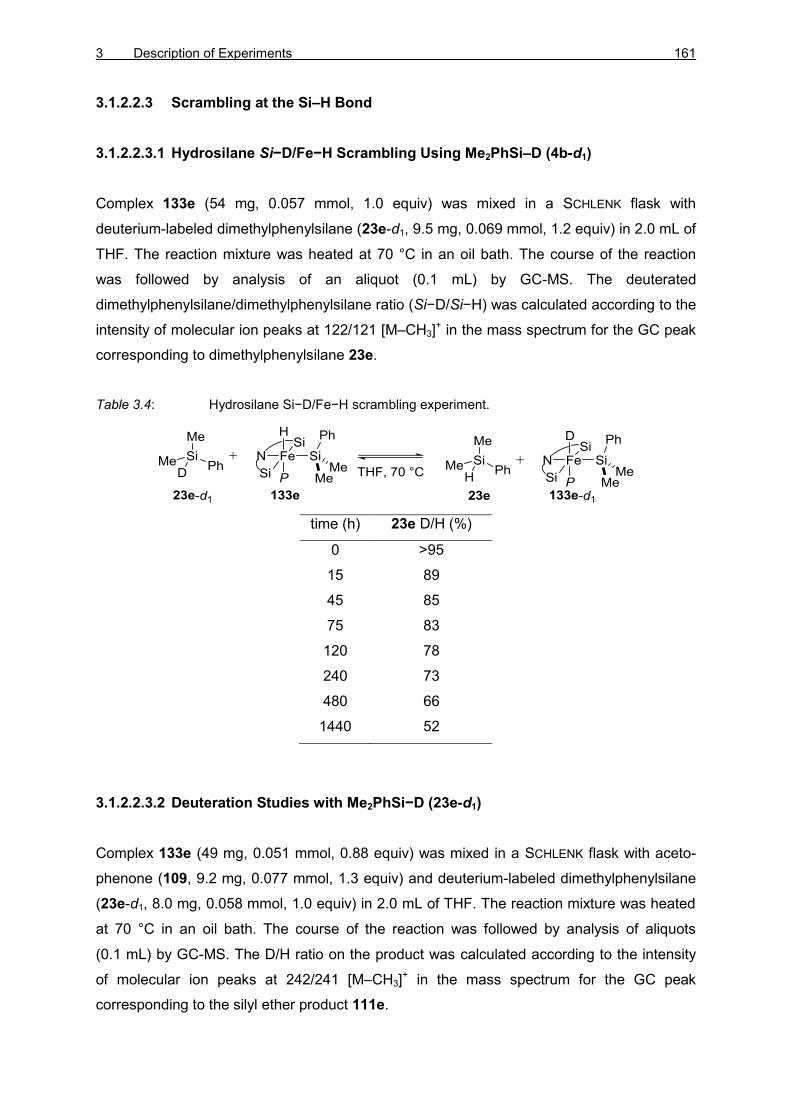
3 Description of Experiments 161
3.1.2.2.3 Scrambling at the Si–H Bond
3.1.2.2.3.1 Hydrosilane Si−D/Fe−H Scrambling Using Me2PhSi–D (4b-d1)
Complex 133e (54 mg, 0.057 mmol, 1.0 equiv) was mixed in a SCHLENK flask with
deuterium-labeled dimethylphenylsilane (23e-d1, 9.5 mg, 0.069 mmol, 1.2 equiv) in 2.0 mL of
THF. The reaction mixture was heated at 70 °C in an oil bath. The course of the reaction
was followed by analysis of an aliquot (0.1 mL) by GC-MS. The deuterated
dimethylphenylsilane/dimethylphenylsilane ratio (Si−D/Si−H) was calculated according to the
intensity of molecular ion peaks at 122/121 [M–CH3]+ in the mass spectrum for the GC peak
corresponding to dimethylphenylsilane 23e.
Table 3.4: Hydrosilane Si−D/Fe−H scrambling experiment.
time (h) 23e D/H (%)
0 >95
15 89
45 85
75 83
120 78
240 73
480 66
1440 52
3.1.2.2.3.2 Deuteration Studies with Me2PhSi−D (23e-d1)
Complex 133e (49 mg, 0.051 mmol, 0.88 equiv) was mixed in a SCHLENK flask with aceto-
phenone (109, 9.2 mg, 0.077 mmol, 1.3 equiv) and deuterium-labeled dimethylphenylsilane
(23e-d1, 8.0 mg, 0.058 mmol, 1.0 equiv) in 2.0 mL of THF. The reaction mixture was heated
at 70 °C in an oil bath. The course of the reaction was followed by analysis of aliquots
(0.1 mL) by GC-MS. The D/H ratio on the product was calculated according to the intensity
of molecular ion peaks at 242/241 [M–CH3]+ in the mass spectrum for the GC peak
corresponding to the silyl ether product 111e.

162 EXPERIMENTAL PART
Table 3.5: Hydrosilylation of acetophenone 109 with deuterium-labeled hydrosilane 23e-d1.
time
(min)
23e-d1 >95% D 23e-d1 ca. 50% D
conversion 111e D/H (%) conversion 111e D/H (%)
15 2 48
20 19 90
30 78
45 39
60 31 80
75 40
120 10 38 78
240 77
360 25 36
480 77
600 23 38
1440 63 78
1560 74 42
2880 80 45
4380 85 48
6960 >99 50
3.1.2.2.4 Scrambling at the C−H Bond
3.1.2.2.4.1 Scrambling Experiment with Deuterated Silyl Ether (8eb-d1)
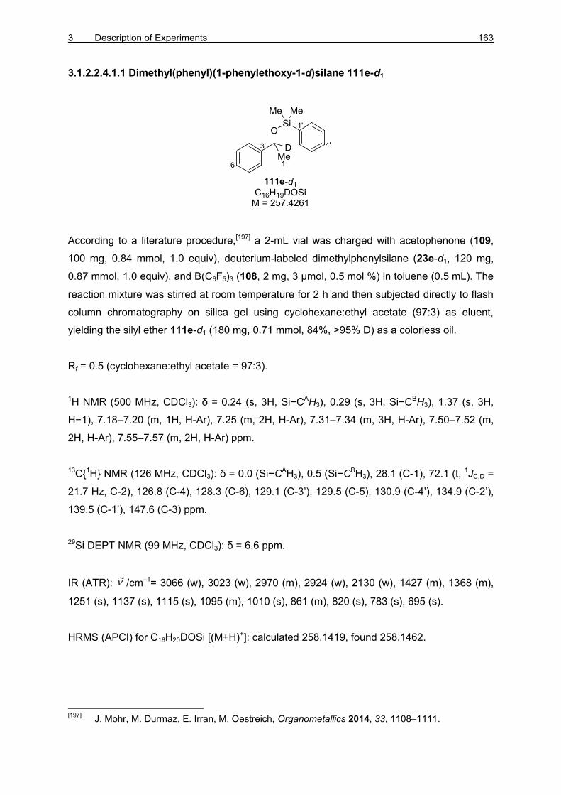
3 Description of Experiments 163
3.1.2.2.4.1.1 Dimethyl(phenyl)(1-phenylethoxy-1-d)silane 111e-d1
According to a literature procedure,[197] a 2-mL vial was charged with acetophenone (109,
100 mg, 0.84 mmol, 1.0 equiv), deuterium-labeled dimethylphenylsilane (23e-d1, 120 mg,
0.87 mmol, 1.0 equiv), and B(C6F5)3 (108, 2 mg, 3 µmol, 0.5 mol %) in toluene (0.5 mL). The
reaction mixture was stirred at room temperature for 2 h and then subjected directly to flash
column chromatography on silica gel using cyclohexane:ethyl acetate (97:3) as eluent,
yielding the silyl ether 111e-d1 (180 mg, 0.71 mmol, 84%, >95% D) as a colorless oil.
Rf = 0.5 (cyclohexane:ethyl acetate = 97:3).
1H NMR (500 MHz, CDCl3): δ = 0.24 (s, 3H, Si−CAH3), 0.29 (s, 3H, Si−CBH3), 1.37 (s, 3H,
H−1), 7.18–7.20 (m, 1H, H-Ar), 7.25 (m, 2H, H-Ar), 7.31–7.34 (m, 3H, H-Ar), 7.50–7.52 (m,
2H, H-Ar), 7.55–7.57 (m, 2H, H-Ar) ppm.
13C{1H} NMR (126 MHz, CDCl3): δ = 0.0 (Si−CAH3), 0.5 (Si−CBH3), 28.1 (C-1), 72.1 (t, 1JC,D =
21.7 Hz, C-2), 126.8 (C-4), 128.3 (C-6), 129.1 (C-3’), 129.5 (C-5), 130.9 (C-4’), 134.9 (C-2’),
139.5 (C-1’), 147.6 (C-3) ppm.
29Si DEPT NMR (99 MHz, CDCl3): δ = 6.6 ppm.
IR (ATR): /cm–1= 3066 (w), 3023 (w), 2970 (m), 2924 (w), 2130 (w), 1427 (m), 1368 (m),
1251 (s), 1137 (s), 1115 (s), 1095 (m), 1010 (s), 861 (m), 820 (s), 783 (s), 695 (s).
HRMS (APCI) for C16H20DOSi [(M+H)+]: calculated 258.1419, found 258.1462.
[197]
J. Mohr, M. Durmaz, E. Irran, M. Oestreich, Organometallics 2014, 33, 1108–1111.
~

164 EXPERIMENTAL PART
3.1.2.2.4.1.2 Scrambling Experiment
Deuterium-labeled silyl ether 111e-d1 (13 mg, 0.049 mmol, 1.1 equiv) and iron hydride
complex 133e (43 mg, 0.045 mmol, 1.0 equiv) were dissolved in THF (2.0 mL), stirred at
70 °C, and the reaction was followed by analysis of an aliquot (0.1 mL) by GC-MS. The H/D
ratio of the product was calculated according to the intensity of peaks at 242/241 [M–CH3]+ in
the mass spectrum for the GC peak corresponding to the silyl ether product 111e.
Table 3.6: Scrambling at the C−H Bond
time (h) 111e D/H (%)
0 99
5 98
10 99
20 99
32 99
60 98
120 99
240 98
480 98
1440 98
2880 92
4320 93
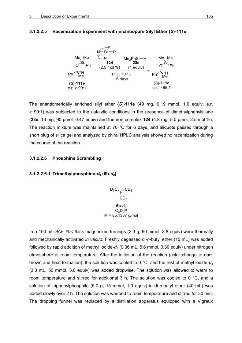
3 Description of Experiments 165
3.1.2.2.5 Racemization Experiment with Enantiopure Silyl Ether (S)-111e
The enantiomerically enriched silyl ether (S)-111e (49 mg, 0.19 mmol, 1.0 equiv, e.r.
> 99:1) was subjected to the catalytic conditions in the presence of dimethylphenylsilane
(23e, 13 mg, 90 µmol, 0.47 equiv) and the iron complex 124 (4.8 mg, 5.0 µmol, 2.5 mol %).
The reaction mixture was maintained at 70 °C for 6 days, and aliquots passed through a
short plug of silica gel and analyzed by chiral HPLC analysis showed no racemization during
the course of the reaction.
3.1.2.2.6 Phosphine Scrambling
3.1.2.2.6.1 Trimethylphosphine-d9 (6b-d9)
In a 100-mL SCHLENK flask magnesium turnings (2.3 g, 90 mmol, 3.8 equiv) were thermally
and mechanically activated in vacuo. Freshly degassed di-n-butyl ether (15 mL) was added
followed by rapid addition of methyl iodide-d3 (0.36 mL, 5.6 mmol, 0.30 equiv) under nitrogen
atmosphere at room temperature. After the initiation of the reaction (color change to dark
brown and heat formation), the solution was cooled to 0 °C, and the rest of methyl iodide-d3
(3.3 mL, 50 mmol, 3.0 equiv) was added dropwise. The solution was allowed to warm to
room temperature and stirred for additional 3 h. The solution was cooled to 0 °C, and a
solution of triphenylphosphite (5.0 g, 15 mmol, 1.0 equiv) in di-n-butyl ether (40 mL) was
added slowly over 2 h. The solution was warmed to room temperature and stirred for 30 min.
The dropping funnel was replaced by a distillation apparatus equipped with a Vigreux

166 EXPERIMENTAL PART
column (10 cm), and the desired deuterated phosphine 6b-d9 (560 mg, 6.6 mmol, 44%) was
distilled at 160 °C (oil bath).
b.p.: 38 °C.
2H NMR (77 MHz, C6D6/C6H6): δ = 0.72 ppm.
13C{1H} NMR (176 MHz, C6D6/C6H6): δ = 15.4 (dsept, JC-P = 6.7, JC,D = 16.4 Hz) ppm.
31P NMR (202 MHz, C6D6/C6H6): δ = –65.5 ppm.
The spectroscopic data for 6b-d9 are in accordance with those reported.[198]
3.1.2.2.6.2 Scrambling between Complex 133e and Trimethylphosphine-d9 (6b-d9)
Complex 133e (10 mg, 0.011 mmol 1.0 equiv) was mixed with trimethylphosphine-d9 (6b-d9,
2.5 mg, 0.029 mmol, 2.7 equiv), dissolved in C6D6 (0.5 mL) in a J. YOUNG NMR tube, heated
to 70 °C, and monitored by 1H and 2H NMR spectroscopy. Slow formation of 133e-d9 was
observed.
Selected NMR data for 133e-d9
1H,31P HMQC NMR (500 MHz / 203 MHz, C6H6/C6D6, 298 K): δ(1H) = –13.9 / δ(31P) = 12.4
ppm.
[198]
a) T. T. Wenzel, R. G. Bergman, J. Am. Chem. Soc. 1986, 108, 4856–4867; b) A. Kornath, F.
Neumann, H. Oberhammer, Inorg. Chem. 2003, 42, 2894–2901.
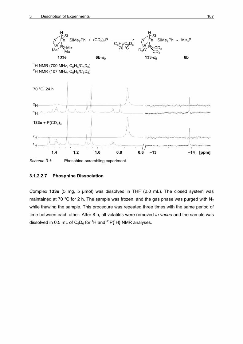
3 Description of Experiments 167
Scheme 3.1: Phosphine-scrambling experiment.
3.1.2.2.7 Phosphine Dissociation
Complex 133e (5 mg, 5 µmol) was dissolved in THF (2.0 mL). The closed system was
maintained at 70 °C for 2 h. The sample was frozen, and the gas phase was purged with N2
while thawing the sample. This procedure was repeated three times with the same period of
time between each other. After 8 h, all volatiles were removed in vacuo and the sample was
dissolved in 0.5 mL of C6D6 for 1H and 31P{1H} NMR analyses.

168 EXPERIMENTAL PART
Scheme 3.2: Phosphine-dissociation experiment.
3.1.2.2.7.1 Phosphine Dissociation in the Presence of Acetophenone (109)
Complex 133e (5 mg, 5 µmol, 1 equiv) was dissolved in THF (2.0 mL). Acetophenone (109,
2 mg, 0.02 mmol, 4 equiv) was added and the closed system was heated up to 70 °C for a
period of 2 h. The sample was frozen, and the gas phase was changed by three purge-
cycles with N2 while thawing the sample. This procedure was repeated three times with the
same period of time between each other. After 8 h, all volatiles were removed in vacuo and
the sample was dissolved in C6D6 (0.5 mL) for 1H and 31P{1H} NMR analyses.

3 Description of Experiments 169
Scheme 3.3: Phosphine-dissociation experiment in the presence of acetophenone 109.
3.1.2.2.8 Silyl Scrambling
Complex 133e (10 mg, 0.011 mmol 1.0 equiv) was mixed with methyldiphenylsilane 23g
(4.0 mg, 0.020 mmol, 1.8 equiv) in C6D6. The sample was closed under nitrogen in a J.
YOUNG NMR tube, heated to 70 °C, and monitored by 1H NMR spectroscopy.

170 EXPERIMENTAL PART
Selected NMR data for 136e-d6:
1H NMR (500 MHz, C6D6): δ = –15.69 (s, 2JH-Si = 23.8 Hz, 1H, Fe–H) ppm.
1H,29Si HMQC NMR (500 MHz / 99 MHz, C6D6): δ(1H) = –15.7 / δ(29Si) = 22.2 (SiMe2Ph),
δ(1H) = –15.7 / δ(29Si) = 84.5 [Si(II)] ppm.
Selected NMR data for 136g-d6:
1H NMR (500 MHz, C6D6): δ = –15.50 (s, 2JH,Si = 23.7 Hz, 1H, Fe–H) ppm.
1H,29Si HMQC NMR (500 MHz / 99 MHz, C6D6): δ(1H) = –15.5 / δ(29Si) = 27.7 (SiMe2Ph),
δ(1H) = –15.5 / δ(29Si) = 83.0 [Si(II)] ppm.
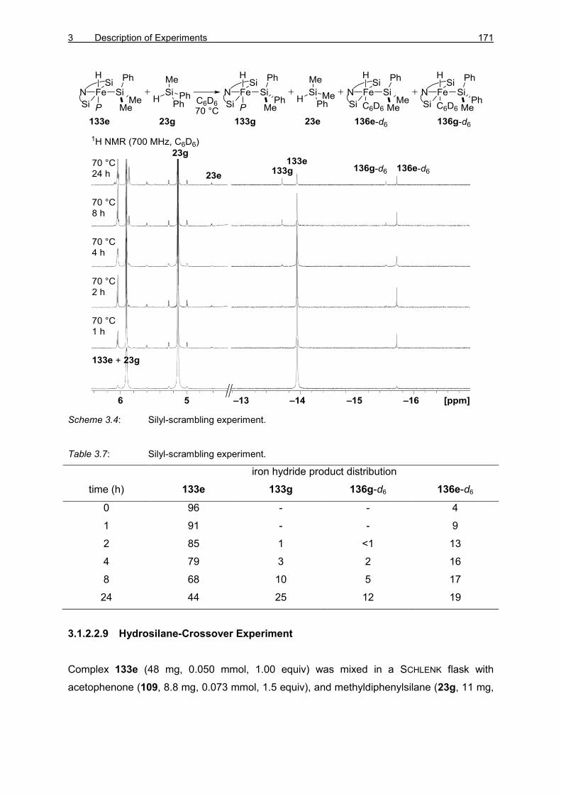
3 Description of Experiments 171
Scheme 3.4: Silyl-scrambling experiment.
Table 3.7: Silyl-scrambling experiment.
iron hydride product distribution
time (h) 133e 133g 136g-d6 136e-d6
0 96 - - 4
1 91 - - 9
2 85 1 <1 13
4 79 3 2 16
8 68 10 5 17
24 44 25 12 19
3.1.2.2.9 Hydrosilane-Crossover Experiment
Complex 133e (48 mg, 0.050 mmol, 1.00 equiv) was mixed in a SCHLENK flask with
acetophenone (109, 8.8 mg, 0.073 mmol, 1.5 equiv), and methyldiphenylsilane (23g, 11 mg,

172 EXPERIMENTAL PART
0.053 mmol, 1.1 equiv) in 2.0 mL of THF. The reaction mixture was heated at 70 °C with an
oil bath. The course of the reaction was followed by analysis of aliquots (0.1 mL) by GC-MS.
Table 3.8: Hydrosilane-crossover experiment.
time (min) conversion (%) ratio 111g/111e (%)
15 23 100
45 27 100
75 42 97
120 51 96
240 59 95
480 71 95
720 69 94
960 76 94
3.1.2.2.10 Hydrosilylation with Silicon-Stereogenic Hydrosilane
3.1.2.2.10.1 Catalytic Reaction between Acetophenone (109) with Enantioenriched
Acyclic Hydrosilane (SiS)-23c
Acetophenone (109, 60 mg, 0.50 mmol, 1.0 equiv), (SiS)-isopropylmethylphenylsilane [(SiS)-
23c, 82 mg, 0.50 mmol, 1.0 equiv, e.r. > 95:5], and the iron hydride complex 133e (49 mg,
0.052 mmol, 10 mol %) were dissolved toluene (3 mL). The reaction mixture was maintained
at 70 °C in an oil bath for 6 days reaching ca. 60% conversion. Purification by flash column
chromatography using n-pentane:diethyl ether (99:1) as eluting solvent mixture gave silyl

3 Description of Experiments 173
ether 111c (44 mg, 0.15 mmol, 31% yield, d.r. = 56:44) and unreacted hydrosilane (SiS)-23c
(10 mg, 0.07 mmol, 15%, e.r. > 95:5).
3.1.2.2.10.2 Reductive Si–O Bond Cleavage of Silyl Ether 111c
According to GP2, a SCHLENK tube equipped with a magnetic stir bar and a reflux condenser
was charged with a solution of the silyl ether 111c (25 mg, 0.089 mmol, 1.0 equiv) in
n-heptane (1.0 mL). DIBAL−H (9b, 0.5 mL, 0.5 mmol, 6 equiv, 1.0M in n-hexane) was added
in one portion at room temperature, and the resulting reaction mixture was heated to reflux
and maintained at this temperature for 20 h. The reaction mixture was allowed to cool to
room temperature and quenched by careful addition of aqueous HCl (1M, 5 mL). The organic
layer was separated, and the aqueous phase was extracted with tert-butyl methyl ether
(3 × 5 mL). The combined organic layers were washed with brine (5 mL), dried over Na2SO4,
filtered, and the volatiles were evaporated under reduced pressure. The crude product was
purified by flash column chromatography on silica gel using n-pentane/diethyl ether mixtures
(100:0→90:10) as eluent, affording the analytically pure hydrosilane (SiS)-23c (9.3 mg,
0.057 mmol, 64%, e.r. > 95:5) as a colorless oil.
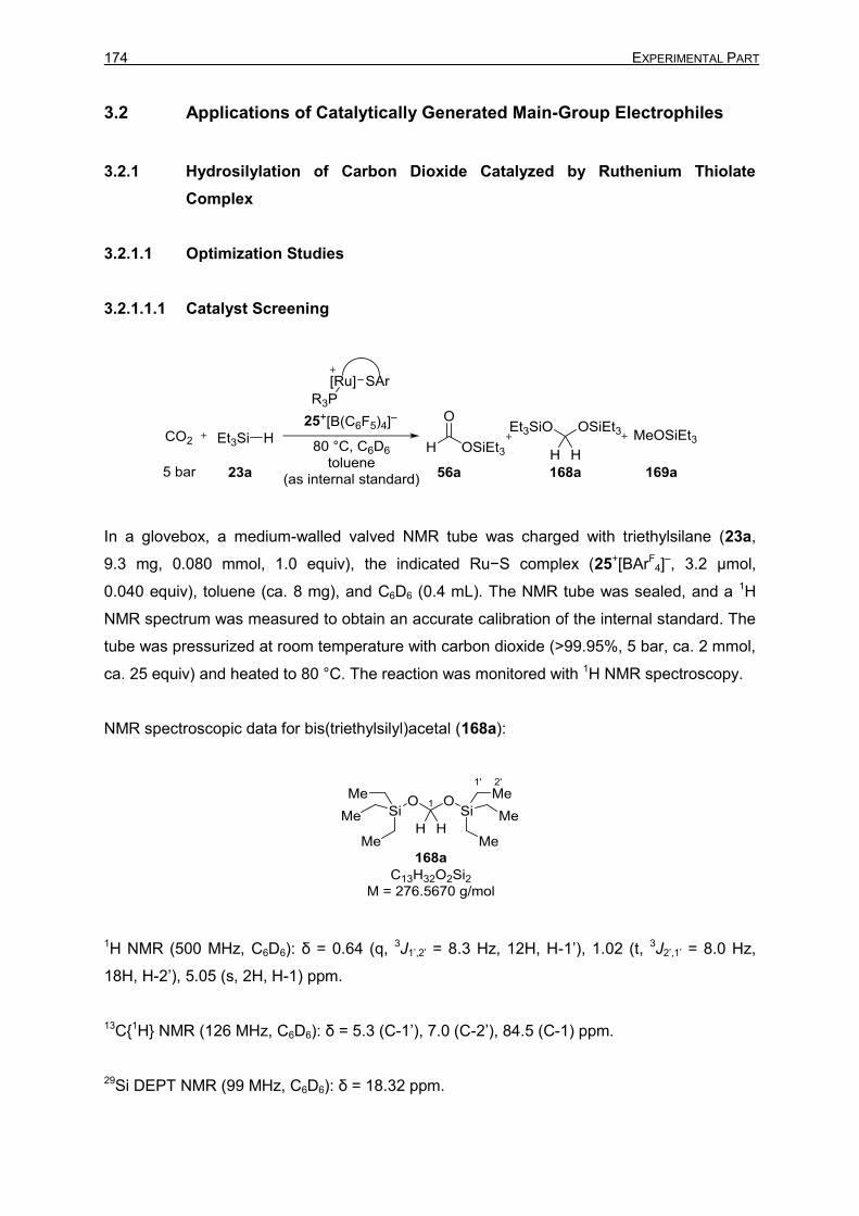
174 EXPERIMENTAL PART
3.2 Applications of Catalytically Generated Main-Group Electrophiles
3.2.1 Hydrosilylation of Carbon Dioxide Catalyzed by Ruthenium Thiolate
Complex
3.2.1.1 Optimization Studies
3.2.1.1.1 Catalyst Screening
In a glovebox, a medium-walled valved NMR tube was charged with triethylsilane (23a,
9.3 mg, 0.080 mmol, 1.0 equiv), the indicated Ru−S complex (25+[BArF4]
–, 3.2 µmol,
0.040 equiv), toluene (ca. 8 mg), and C6D6 (0.4 mL). The NMR tube was sealed, and a 1H
NMR spectrum was measured to obtain an accurate calibration of the internal standard. The
tube was pressurized at room temperature with carbon dioxide (>99.95%, 5 bar, ca. 2 mmol,
ca. 25 equiv) and heated to 80 °C. The reaction was monitored with 1H NMR spectroscopy.
NMR spectroscopic data for bis(triethylsilyl)acetal (168a):
1H NMR (500 MHz, C6D6): δ = 0.64 (q, 3J1’,2’ = 8.3 Hz, 12H, H-1’), 1.02 (t, 3J2’,1’ = 8.0 Hz,
18H, H-2’), 5.05 (s, 2H, H-1) ppm.
13C{1H} NMR (126 MHz, C6D6): δ = 5.3 (C-1’), 7.0 (C-2’), 84.5 (C-1) ppm.
29Si DEPT NMR (99 MHz, C6D6): δ = 18.32 ppm.

3 Description of Experiments 175
The spectroscopic data are in accordance with those reported.[136,137]
3.2.1.1.1.1 Hydrosilylation of Carbon Dioxide Catalyzed by Ru−S Complex 25f+[BArF4]
–
Table 3.9: Conversion and yields of 56a, 168a, and 169a over time with 4 mol % of
25f+[BAr
F4]
–
time (h) conversion
(%)[a]
yield (%) combined
yield (%)
TOF
(h–1)[b] 56a 168a 169a
1 43 <1 45 <1 45 11
4 99 <1 99 1 >99 6.2
[a] Based on hydrosilane consumption using toluene signals as internal standard.
[b]
(conversion/catalyst loading)/time.
3.2.1.1.1.2 Hydrosilylation of Carbon Dioxide Catalyzed by Ru−S Complex 25g+[BArF4]
–
Table 3.10: Conversion and yields of 56a, 168a, and 169a over time with 4 mol % of
25g+[BAr
F4]
–
time (h) conversion
(%)[a]
yield (%) combined
yield (%)
TOF
(h–1)[b] 56a 168a 169a
1 <1 <1 <1 <1 4 <0.01
4 2 <1 2 <1 13 0.12
20 55 3 41 4 45 0.69
48 98 4 89 5 93 0.51
[a] Based on hydrosilane consumption using toluene signals as internal standard.
[b]
(conversion/catalyst loading)/time.

176 EXPERIMENTAL PART
3.2.1.1.1.3 Hydrosilylation of Carbon Dioxide Catalyzed by Ru−S Complex 25h+[BArF4]
–
Table 3.11: Conversion and yields of 56a, 168a, and 169a over time with 4 mol % of
25h+[BAr
F4]
–
time (h) conversion
(%)[a]
yield (%) combined
yield (%)
TOF
(h–1)[b] 56a 168a 169a
1 <1 <1 2 <1 2 0.00
4 6 <1 2 1 3 0.39
20 41 <1 32 2 34 0.51
48 89 <1 92 1 93 0.47
72 99 1 >99 1 >99 0.34
[a] Based on hydrosilane consumption using toluene signals as internal standard.
[b]
(conversion/catalyst loading)/time.
3.2.1.1.2 Hydrosilane Screening
In a glove box, a medium-walled valved NMR tube was charged with hydrosilane
(0.080 mmol, 1.0 equiv), Ru−S complex 25f+[BArF4]
– (2.3 mg, 1.6 µmol, 0.020 equiv or
4.5 mg, 3.2 µmol, 0.040 equiv), toluene (ca. 8 mg), and C6D6 (0.4 mL). The NMR tube was
sealed, and a 1H NMR spectrum was measured to obtain an accurate calibration of the
internal standard. The tube was pressurized at room temperature with carbon dioxide
(>99.95%, 5 bar, ca. 2 mmol, ca. 25 equiv) and heated to 80 °C. The reaction was monitored
with 1H NMR spectroscopy.

3 Description of Experiments 177
3.2.1.1.2.1 Hydrosilylation of Carbon Dioxide with Triethylsilane (23a)
Table 3.12: Conversion and yields of 56a, 168a, and 169a over time with 2 mol % of
25f+[BAr
F4]
–
time (h) conversion
(%)[a]
yield (%) combined
yield (%)
TOF
(h–1)[b] 56a 168a 169a
1 17 <1 15 <1 15 8.6
2 46 <1 44 1 44 11
9 73 9 67 1 76 4.0
24 89 15 73 1 89 1.9
32 95 18 80 1 98 1.5
47 97 18 79 1 97 1.0
[a] Based on hydrosilane consumption using toluene signals as internal standard.
[b]
(conversion/catalyst loading)/time.
Table 3.13: Conversion and yields of 56a, 168a, and 169a over time with 4 mol % of
25f+[BAr
F4]
–
time (h) conversion
(%)[a]
yield (%) combined
yield (%)
TOF
(h–1)[b] 56a 168a 169a
1 42 <1 42 <1 42 11
2 95 <1 97 <1 97 12
4 100 <1 >99 <1 >99 6.3
[a] Based on hydrosilane consumption using toluene signals as internal standard.
[b]
(conversion/catalyst loading)/time.
3.2.1.1.2.2 Hydrosilylation of Carbon Dioxide with Ethyldimethylsilane (23i)
NMR spectroscopic data for bis(ethyldimethylsilyl)acetal (168i):
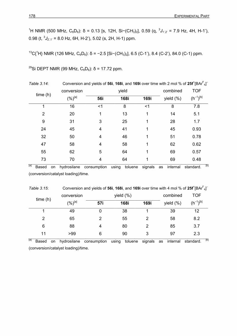
178 EXPERIMENTAL PART
1H NMR (500 MHz, C6D6): δ = 0.13 [s, 12H, Si−(CH3)2], 0.59 (q, 3J1’,2’ = 7.9 Hz, 4H, H-1’),
0.98 (t, 3J2’,1’ = 8.0 Hz, 6H, H-2’), 5.02 (s, 2H, H-1) ppm.
13C{1H} NMR (126 MHz, C6D6): δ = −2.5 [Si−(CH3)2], 6.5 (C-1’), 8.4 (C-2’), 84.0 (C-1) ppm.
29Si DEPT NMR (99 MHz, C6D6): δ = 17.72 ppm.
Table 3.14: Conversion and yields of 56i, 168i, and 169i over time with 2 mol % of 25f+[BAr
F4]
–
time (h) conversion
(%)[a]
yield combined
yield (%)
TOF
(h–1)[b] 56i 168i 169i
1 16 <1 8 <1 8 7.8
2 20 1 13 1 14 5.1
9 31 3 25 1 28 1.7
24 45 4 41 1 45 0.93
32 50 4 46 1 51 0.78
47 58 4 58 1 62 0.62
55 62 5 64 1 69 0.57
73 70 4 64 1 69 0.48
[a] Based on hydrosilane consumption using toluene signals as internal standard.
[b]
(conversion/catalyst loading)/time.
Table 3.15: Conversion and yields of 56i, 168i, and 169i over time with 4 mol % of 25f+[BAr
F4]
–
time (h) conversion
(%)[a]
yield (%) combined
yield (%)
TOF
(h–1)[b] 57i 168i 169i
1 49 0 38 1 39 12
2 65 2 55 2 58 8.2
6 88 4 80 2 85 3.7
11 >99 6 90 3 97 2.3
[a] Based on hydrosilane consumption using toluene signals as internal standard.
[b]
(conversion/catalyst loading)/time.

3 Description of Experiments 179
3.2.1.1.2.3 Hydrosilylation of Carbon Dioxide with Methyldiphenylsilane (23g)
NMR spectroscopic data for bis(methyldiphenylsilyl)acetal (168g):
1H NMR (500 MHz, C6D6): δ = 0.13 (s, 6H, Si−CH3), 5.21 (s, 2H, H-1), 7.16–7.18 (m, 12H, H-
3’,H-4’), 7.59–7.61 (m, 8H, H-2’) ppm.
13C{1H} NMR (126 MHz, C6D6): δ = −2.6 (Si−(CH3), 84.9 (C-1), 128.2 (C-3’), 129.7 (C-4’),
134.5 (C-2’), 135.9 (C-1’) ppm.
29Si DEPT NMR (99 MHz, C6D6): δ = −2.74 ppm.
Table 3.16: Conversion and yields of 56g, 168g, and 169g over time with 2 mol % of
25f+[BAr
F4]
–
time (h) conversion
(%)[a]
yield (%) combined
yield (%)
TOF
(h–1)[b] 56g 168g 169g
1 8 <1 7 <1 7 3.9
2 18 <1 13 1 13 4.5
9 22 1 20 1 22 1.2
24 28 2 22 1 24 0.58
32 30 2 22 1 25 0.47
47 31 2 23 1 26 0.33
55 31 2 23 1 25 0.28
73 33 2 24 1 27 0.23
[a] Based on hydrosilane consumption using toluene signals as internal standard.
[b]
(conversion/catalyst loading)/time.

180 EXPERIMENTAL PART
Table 3.17: Conversion and yields of 56g, 168g, and 169g over time with 4 mol % of
25f+[BAr
F4]
–
time (h) conversion
(%)[a]
yield (%) combined
yield (%)
TOF
(h–1)[b] 56g 168g 169g
1 48 1 36 2 37 12
2 64 2 50 3 53 8.0
6 81 1 67 3 70 3.4
11 88 3 72 3 76 2.0
24 96 4 80 3 85 1.0
36 98 5 79 3 85 0.68
[a] Based on hydrosilane consumption using toluene signals as internal standard.
[b]
(conversion/catalyst loading)/time.
3.2.1.1.2.4 Hydrosilylation of Carbon Dioxide with Dimethylphenylsilane (23e)
NMR spectroscopic data for bis(dimethylphenylsilyl)acetal (168e):
1H NMR (500 MHz, C6D6): δ = 0.34 [s, 12H, Si−(CH3)2], 5.06 (s, 2H, C-1), 7.19–7.21 (m, 6H,
H-3’,H-4’), 7.55–7.57 (m, 4H, H-2’) ppm.
13C{1H} NMR (126 MHz, C6D6): δ = −1.5 [Si−(CH3)2], 84.5 (C-1), 128.2 (C-3’), 129.5 (C-4’),
133.5 (C-2’), 137.6 (C-1’) ppm.
29Si DEPT NMR (99 MHz, C6D6): δ = 6.99 ppm.

3 Description of Experiments 181
Table 3.18: Conversion and yields of 56e, 168e, and 169e over time with 2 mol % of
25f+[BAr
F4]
–
time (h) conversion
(%)[a]
yield (%) combined
yield (%)
TOF
(h–1)[b] 56e 168e 169e
1 12 <1 7 1 7 6.2
2 21 1 13 1 14 5.2
9 29 3 24 2 27 1.6
24 40 4 36 2 40 0.84
32 48 4 39 2 44 0.74
47 54 5 45 2 50 0.58
55 56 6 50 2 56 0.51
73 63 5 55 2 60 0.43
[a] Based on hydrosilane consumption using toluene signals as internal standard.
[b]
(conversion/catalyst loading)/time.
Table 3.19: Conversion and Yields of 56e, 168e, and 169e over Time with 4 mol % of
25f+[BAr
F4]
–
time (h) conversion
(%)[a]
yield (%) combined
yield (%)
TOF
(h–1)[b] 56e 168e 169e
1 38 <1 26 3 27 9.5
2 47 <1 37 4 38 5.9
6 64 <1 48 4 49 2.7
11 71 1 56 4 59 1.6
24 81 2 68 5 72 0.85
36 85 3 72 5 77 0.59
75 96 5 79 5 86 0.32
[a] Based on hydrosilane consumption using toluene signals as internal standard.
[b]
(conversion/catalyst loading)/time.
3.2.1.2 Carbon dioxide Hydrosilylation to Silylated Methanol (169)

182 EXPERIMENTAL PART
In a glovebox a medium walled valved NMR tube was charged with ethyldimethylsilane (23i,
32 mg, 0.32 mmol, 1.0 equiv), Ru−S complex (25f+[BAr
F4]
–, 4.6 mg, 3.2 µmol, 0.01 equiv) and
toluene-d8 (0.4 mL). The NMR tube was sealed, and an 1H NMR spectrum was measured.
The tube was pressurized with carbon dioxide in argon mixture (18 ± 1.8 % CO2 in Ar, 5 bar,
ca. 0.1 mmol, ca. 0.3 equiv) at room temperature and heated to 80 °C. The reaction was
monitored with 1H NMR spectroscopy. After no further hydrosilane consumption was
observed (between 3 and 4 days), the reaction was heated to 150 °C and further monitored
with 1H NMR spectroscopy.
NMR spectroscopic data for ethyl(methoxy)dimethylsilane (169i):
1H NMR (500 MHz, toluene-d8): δ = 0.12 [s, 6H, Si−(CH3)2], 0.52−0.58 (m, 2H, H-1),
0.97−1.03 (m, 3H, H-2), 3.31 (s, 3H, O-CH3) ppm.
13C{1H} NMR (126 MHz, toluene-d8): δ = −2.7 [Si−(CH3)2], 4.6 (C-1), 8.2 (C-2), 49.9 (O−CH3)
ppm.
1H,29Si HMBC NMR (500 / 99 MHz, toluene-d8): δ(1H) = –0.1, 0.6, 1.0, 3.3 ppm / δ(29Si) = –
18.5 ppm.
NMR spectroscopic data for 1,3-diethyltetramethyldisiloxane (180i)
1H NMR (500 MHz, toluene-d8): δ = 0.12 [s, 12H, Si−(CH3)2], 0.52−0.58 (m, 4H, H-1),
0.97−1.03 (m, 6H, H-2) ppm.

3 Description of Experiments 183
13C{1H} NMR (126 MHz, toluene-d8): δ = −0.1 [Si−(CH3)2], 7.0 (C-1), 10.4 (C-2) ppm.
29Si DEPT NMR (99 MHz, toluene-d8): δ = 8.19 ppm.
The spectroscopic data are in accordance with those reported.[82]
Table 3.20: Yield of 168i and 169i over time with 1 mol % of 25f+[BAr
F4]
–
time (d) T (°C) yield (%)[a]
ratio (168i:169I) 168i 169i
0.17
80
17 <1 98:2
1 60 2 96:4
2 73 4 95:5
3 79 4 95:5
4 81 4 95:5
5
150
79 21 79:21
6 59 28 68:32
7 48 37 57:43
8 38 44 46:54
9 31 50 38:62
10 24 56 30:70
11 19 56 25:75
13 13 54 19:81
15 8 47 14:86
16 6 45 11:89
17 5 43 10:90
18 4 40 9:91
19 3 38 8:92
20 3 41 7:93
22 3 40 6:94
24 1 39 3:97
[a] Residual signals for the hydrosilane used as internal standard. The maximum combined yield at 5
days was calibrated as 100% yield.

184 EXPERIMENTAL PART
3.2.2 Catalytic Generation of Alumenium Ions by Cooperative Al–H Bond
Activation in Defluorinative FRIEDEL–CRAFTS Alkylation
3.2.2.1 Synthesis of [(iPr3P)Ru(SDmp)]+2[B12Cl12]
2– [25g]2+[B12Cl12]
2–
In a glovebox a 10-mL SCHLENK tube was charged with [(iPr3P)Ru(SDmp)Cl] (228g, 100 mg,
160 µmol, 2.0 equiv) and [Na2B12Cl12 · nH2O] (50 mg, 83 µmol, 1.1 equiv). Chlorobenzene (4
mL) is added to afford a red solution. Ethyldimethylsilane (23i, 0.5 mL, excess) was added,
and the solution was stirred over night at room temperature (gas evolution). The solution
was removed from the glovebox, cooled to 0 °C, and concentrated in vacuo. The residue
was dissolved in chlorobenzene (1 mL), filtered through a PTFE syringe filter, and benzene
(3 mL) was added. The resulting solution was frozen and the solvent is sublimated in vacuo.
The resulting green solid was further dried in vacuo using a turbomolecular pump (1 10–5
mbar, 40 °C, 6 h) affording the desired complex as a green air-sensitive solid (130 mg,
71 µmol, 92%).
1H NMR (500 MHz, o-Cl2C6D4): δ = 0.76 [dd, 3JCH3,P = 14.6 Hz, 3JCH
3,CH = 7.2 Hz, 18H,
PCH(CH3)2], 1.69 (s, 6H, 2’-CH3), 1.89−1.95 [m, 3H, PCH(CH3)2], 1.95 (s, 6H, 2’’-CH3), 2.00
(s, 3H, 4’’-CH3), 2.09 (s, 3H, 4’-CH3), 4.67 (s, 2H, H-3’), 6.75 (s, 2H, H-3’’), 6.94 (m, 1H, H-
3), 7.24−7.25 (m, 1H, H-5), 7.55−7.56 (m, 1H, H-4) ppm.
11B NMR (161 MHz, o-Cl2C6D4): δ = −11.7 ppm.
13C{1H} NMR (126 MHz, o-Cl2C6D4): δ = 18.3 (2’-CH3), 19.6 [P(CH(CH3)], 19.8 (4’-CH3), 20.4
(2’’-CH3), 21.0 (4’’-CH3), 24.9 [d, 1JC,P = 20.9 Hz, [P(CH(CH3)], 71.4 (C-3’), 102.6 (C-2’),
107.1 (C-4’), 109.2 (d, J1’,P = 8.5 Hz, C-1’), 128.1 (C-5), 128.4 (C-4), 128.6 (C-3’’), 132.1 (C-
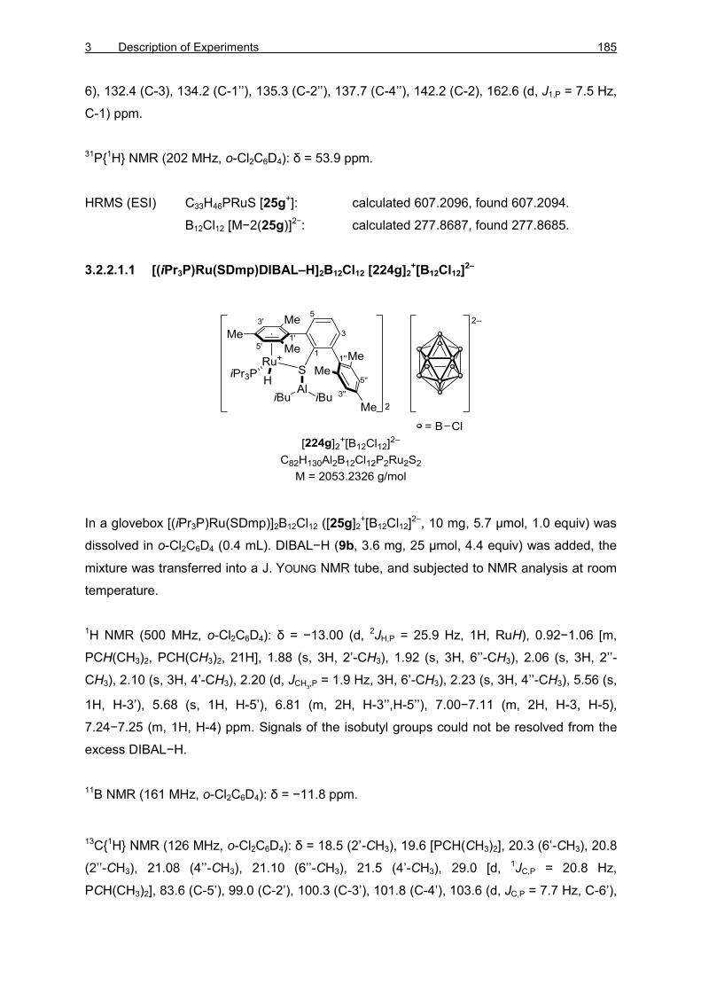
3 Description of Experiments 185
6), 132.4 (C-3), 134.2 (C-1’’), 135.3 (C-2’’), 137.7 (C-4’’), 142.2 (C-2), 162.6 (d, J1,P = 7.5 Hz,
C-1) ppm.
31P{1H} NMR (202 MHz, o-Cl2C6D4): δ = 53.9 ppm.
HRMS (ESI) C33H46PRuS [25g+]: calculated 607.2096, found 607.2094.
B12Cl12 [M−2(25g)]2−: calculated 277.8687, found 277.8685.
3.2.2.1.1 [(iPr3P)Ru(SDmp)DIBAL–H]2B12Cl12 [224g]2+[B12Cl12]
2–
In a glovebox [(iPr3P)Ru(SDmp)]2B12Cl12 ([25g]2+[B12Cl12]
2–, 10 mg, 5.7 µmol, 1.0 equiv) was
dissolved in o-Cl2C6D4 (0.4 mL). DIBAL−H (9b, 3.6 mg, 25 µmol, 4.4 equiv) was added, the
mixture was transferred into a J. YOUNG NMR tube, and subjected to NMR analysis at room
temperature.
1H NMR (500 MHz, o-Cl2C6D4): δ = −13.00 (d, 2JH,P = 25.9 Hz, 1H, RuH), 0.92−1.06 [m,
PCH(CH3)2, PCH(CH3)2, 21H], 1.88 (s, 3H, 2’-CH3), 1.92 (s, 3H, 6’’-CH3), 2.06 (s, 3H, 2’’-
CH3), 2.10 (s, 3H, 4’-CH3), 2.20 (d, JCH3,P = 1.9 Hz, 3H, 6’-CH3), 2.23 (s, 3H, 4’’-CH3), 5.56 (s,
1H, H-3’), 5.68 (s, 1H, H-5’), 6.81 (m, 2H, H-3’’,H-5’’), 7.00−7.11 (m, 2H, H-3, H-5),
7.24−7.25 (m, 1H, H-4) ppm. Signals of the isobutyl groups could not be resolved from the
excess DIBAL−H.
11B NMR (161 MHz, o-Cl2C6D4): δ = −11.8 ppm.
13C{1H} NMR (126 MHz, o-Cl2C6D4): δ = 18.5 (2’-CH3), 19.6 [PCH(CH3)2], 20.3 (6’-CH3), 20.8
(2’’-CH3), 21.08 (4’’-CH3), 21.10 (6’’-CH3), 21.5 (4’-CH3), 29.0 [d, 1JC,P = 20.8 Hz,
PCH(CH3)2], 83.6 (C-5’), 99.0 (C-2’), 100.3 (C-3’), 101.8 (C-4’), 103.6 (d, JC,P = 7.7 Hz, C-6’),

186 EXPERIMENTAL PART
112.6 (d, J1’,P = 4.4 Hz, C-1’), 128.4 (C-5), 128.5 (C-4), 128.7 (C-3’’), 129.7 (C-5’’), 134.2 (C-
3), 134.4 (C-1’’), 135.2 (C-2’’), 135.9 (C-6’’), 137.2 (C-4’’), 137.9 (C-6), 142.6 (d, J1,P = 3.0
Hz, C-1), 145.7 (C-2) ppm.
27Al NMR (130 HMz, o-Cl2C6D4): δ = 77 (br s) ppm. The signal overlaps with DIBAL−H.
31P{1H} NMR (202 MHz, o-Cl2C6D4): δ = 62.3 ppm.
3.2.2.2 Defluorinative FRIEDEL–CRAFTS Alkylation
3.2.2.2.1 4-(4-Methylbenzyl)-1,1’-biphenyl (230)
In a 5-mL vial in a glovebox, 4-trifluoromethyl biphenyl (229, 8.9 mg, 40 µmol, 1.0 equiv),
ruthenium thiolate complex [25g]2+[B12Cl12]
2– (1.7 mg, 1 µmol, 2.5 mol %), and toluene
(18 mg, 200 µmol, 5.0 equiv) were dissolved in fluorobenzene (100 µL). The solution was
mixed, and DIBAL−H (9b, 23 mg, 160 µmol, 4 equiv) was added. The solution was
maintained at room temperature for 24 h. The reaction was removed from the glovebox,
quenched by the addition of cyclohexane:EtOH (95:5, 2 mL), transferred to a 10-mL flask
containing ca. 3 g silica gel, and concentrated in vacuo. The crude product was purified by
flash chromatography using cyclohexane:toluene (95:5) as eluent, giving the desired product
230 as a 83:17 mixture of regioisomers (4.1 mg, 16 µmol, 40%).
m.p.: 77 °C (cyclohexane).
Rf: 0.25 (cyclohexane:toluene = 95:5).
GLC: tR = 23.8 min (major), tR = 23.8 min (minor).
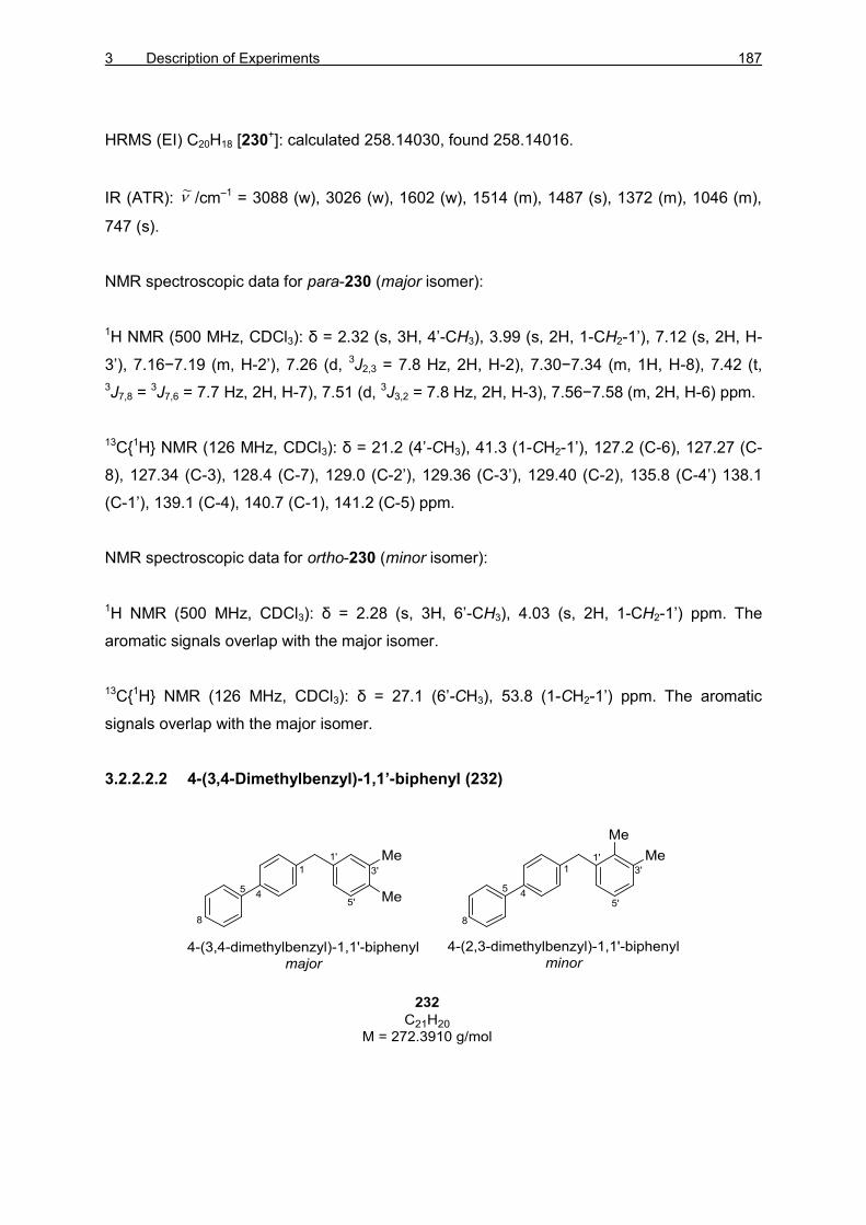
3 Description of Experiments 187
HRMS (EI) C20H18 [230+]: calculated 258.14030, found 258.14016.
IR (ATR): /cm–1 = 3088 (w), 3026 (w), 1602 (w), 1514 (m), 1487 (s), 1372 (m), 1046 (m),
747 (s).
NMR spectroscopic data for para-230 (major isomer):
1H NMR (500 MHz, CDCl3): δ = 2.32 (s, 3H, 4’-CH3), 3.99 (s, 2H, 1-CH2-1’), 7.12 (s, 2H, H-
3’), 7.16−7.19 (m, H-2’), 7.26 (d, 3J2,3 = 7.8 Hz, 2H, H-2), 7.30−7.34 (m, 1H, H-8), 7.42 (t,
3J7,8 = 3J7,6 = 7.7 Hz, 2H, H-7), 7.51 (d, 3J3,2 = 7.8 Hz, 2H, H-3), 7.56−7.58 (m, 2H, H-6) ppm.
13C{1H} NMR (126 MHz, CDCl3): δ = 21.2 (4’-CH3), 41.3 (1-CH2-1’), 127.2 (C-6), 127.27 (C-
8), 127.34 (C-3), 128.4 (C-7), 129.0 (C-2’), 129.36 (C-3’), 129.40 (C-2), 135.8 (C-4’) 138.1
(C-1’), 139.1 (C-4), 140.7 (C-1), 141.2 (C-5) ppm.
NMR spectroscopic data for ortho-230 (minor isomer):
1H NMR (500 MHz, CDCl3): δ = 2.28 (s, 3H, 6’-CH3), 4.03 (s, 2H, 1-CH2-1’) ppm. The
aromatic signals overlap with the major isomer.
13C{1H} NMR (126 MHz, CDCl3): δ = 27.1 (6’-CH3), 53.8 (1-CH2-1’) ppm. The aromatic
signals overlap with the major isomer.
3.2.2.2.2 4-(3,4-Dimethylbenzyl)-1,1’-biphenyl (232)
~

188 EXPERIMENTAL PART
In a 5-mL vial in a glovebox 4-trifluoromethyl biphenyl (229, 8.9 mg, 40 µmol, 1.0 equiv),
ruthenium thiolate complex [25g]2+[B12Cl12]
2– (1.7 mg, 1 µmol, 2.5 mol%), and o-xylene
(21 mg, 200 µmol, 5.0 equiv) were dissolved in fluorobenzene (100 µL). The solution was
mixed, and DIBAL−H (9b, 23 mg, 160 µmol, 4 equiv) was added. The solution was
maintained at room temperature for 24 h. The reaction was removed from the glovebox,
quenched by the addition of cyclohexane:EtOH (95:5, 2 mL), transferred to a 10-mL flask
containing ca. 3 g silica gel, and concentrated in vacuo. The crude product was purified by
flash chromatography using cyclohexane:toluene (95:5) as eluent, giving the desired product
232 as a 90:10 mixture of regioisomers (3.4 mg, 12 µmol, 31%).
m.p.: 75 °C (cyclohexane).
Rf: 0.24 (cyclohexane:toluene = 95:5).
GLC: tR = 25.0 min (major), tR = 25.1 min (minor).
HRMS (EI) C21H20 [232+]: calculated 272.15595, found 272.15632.
IR (ATR): /cm–1 = 3024 (w), 2916 (w), 1600 (m), 1502 (m), 1485 (s), 1441 (m), 1019 (m),
741 (s).
NMR spectroscopic data for 1,3,4-232 (major isomer):
1H NMR (500 MHz, CDCl3): δ = 2.24 (s, 3H, 4’-CH3), 2.36 (s, 3H, 3’-CH3), 3.96 (s, 2H, 1-
CH2-1’), 6.97 (dd, 3J6’,5’ = 7.5 Hz, 4J6’,2’ = 1.7 Hz, 1H, H-6’), 7.01 (d, 4J2’,6’ = 1.3 Hz, 1H, H-2’),
7.07 (d, 3J5’,6’ = 7.7 Hz, 1H, H-5’), 7.25−7.28 (m, 2H, H-2), 7.32 (tt, d, 3J8,7 = 7.3 Hz, 4J8,6 = 1.4
Hz, 1H, H-8), 7.41−7.43 (m, 2H, H-7), 7.51 (d, 3J3,4 = 8.3 Hz, 2H, H-3), 7.56−7.58 (m, 2H, H-
6) ppm.
13C{1H} NMR (126 MHz, CDCl3): δ = 19.5 (4’-CH3), 19.9 (3’-CH3), 41.3 (1-CH2-1’), 126.5 (C-
6’), 127.1 (C-8), 127.2 (C-6), 127.3 (C-3), 128.8 (C-7), 129.2 (C-5’), 129.4 (C-2), 130.4 (C-2’)
134.4 (C-3’), 136.8 (C-4’), 138.6 (C-1’), 139.1 (C-4), 140.8 (C-1), 141.2 (C-5) ppm.
NMR spectroscopic data for 1,2,3-232 (minor isomer):
~
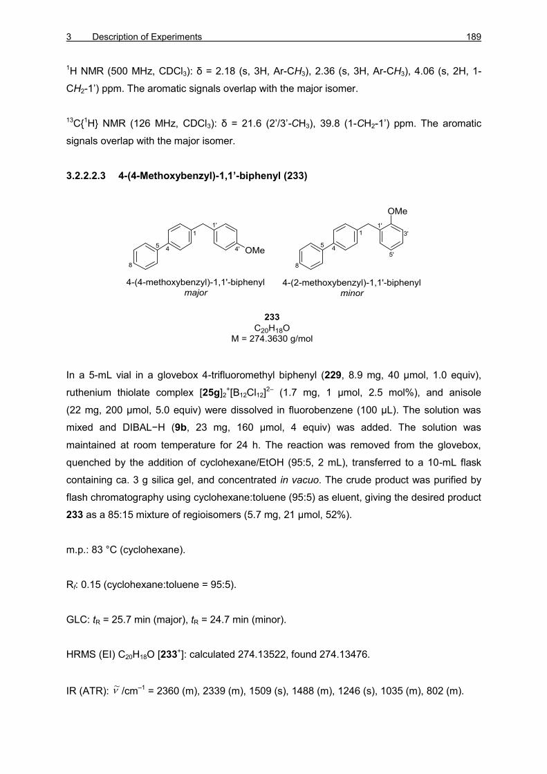
3 Description of Experiments 189
1H NMR (500 MHz, CDCl3): δ = 2.18 (s, 3H, Ar-CH3), 2.36 (s, 3H, Ar-CH3), 4.06 (s, 2H, 1-
CH2-1’) ppm. The aromatic signals overlap with the major isomer.
13C{1H} NMR (126 MHz, CDCl3): δ = 21.6 (2’/3’-CH3), 39.8 (1-CH2-1’) ppm. The aromatic
signals overlap with the major isomer.
3.2.2.2.3 4-(4-Methoxybenzyl)-1,1’-biphenyl (233)
In a 5-mL vial in a glovebox 4-trifluoromethyl biphenyl (229, 8.9 mg, 40 µmol, 1.0 equiv),
ruthenium thiolate complex [25g]2+[B12Cl12]
2– (1.7 mg, 1 µmol, 2.5 mol%), and anisole
(22 mg, 200 µmol, 5.0 equiv) were dissolved in fluorobenzene (100 µL). The solution was
mixed and DIBAL−H (9b, 23 mg, 160 µmol, 4 equiv) was added. The solution was
maintained at room temperature for 24 h. The reaction was removed from the glovebox,
quenched by the addition of cyclohexane/EtOH (95:5, 2 mL), transferred to a 10-mL flask
containing ca. 3 g silica gel, and concentrated in vacuo. The crude product was purified by
flash chromatography using cyclohexane:toluene (95:5) as eluent, giving the desired product
233 as a 85:15 mixture of regioisomers (5.7 mg, 21 µmol, 52%).
m.p.: 83 °C (cyclohexane).
Rf: 0.15 (cyclohexane:toluene = 95:5).
GLC: tR = 25.7 min (major), tR = 24.7 min (minor).
HRMS (EI) C20H18O [233+]: calculated 274.13522, found 274.13476.
IR (ATR): /cm–1 = 2360 (m), 2339 (m), 1509 (s), 1488 (m), 1246 (s), 1035 (m), 802 (m). ~

190 EXPERIMENTAL PART
NMR spectroscopic data for para-233 (major isomer):
1H NMR (500 MHz, CDCl3): δ = 3.79 (s, 3H, O-CH3), 3.97 (s, 2H, 1-CH2-1’), 6.85 (d, 3J3’,2’ =
8.8 Hz, 2H, H-3’), 7.15 (d, 3J2’,3’ = 8.8 Hz, 2H, H-2’), 7.25 (d, 3J2,3 = 8.4 Hz, 2H, H-2),
7.30−7.34 (m, 1H, H-8), 7.40−7.43 (m, 1H, H-7), 7.50−7.52 (m, 2H, H-3), 7.56−7.58 (m, 2H,
H-6) ppm.
13C{1H} NMR (126 MHz, CDCl3): δ = 40.8 (1-CH2-1’), 55.4 (O-CH3), 114.1 (C-3’), 127.17 (C-
6), 127.20 (C-8), 127.3 (C-3), 128.9 (C-7), 129.3 (C-2’), 133.2 (C-2), 139.0 (C-1’), 140.7 (C-
1), 141.2 (C-5), 146.6 (C-4), 158.1 (C-4’) ppm.
NMR spectroscopic data for ortho-233 (minor isomer):
1H NMR (500 MHz, CDCl3): δ = 3.84 (s, 3H, O-CH3), 4.01 (s, 2H, 1-CH2-1’) ppm. The
aromatic signals overlap with the major isomer.

APPENDIX

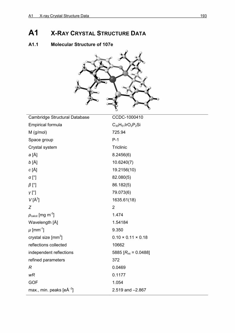
A1 X-ray Crystal Structure Data 193
A1 X-RAY CRYSTAL STRUCTURE DATA
A1.1 Molecular Structure of 107e
Cambridge Structural Database CCDC-1000410
Empirical formula C30H51IrO2P2Si
M (g/mol) 725.94
Space group P-1
Crystal system Triclinic
a [Å] 8.2456(6)
b [Å] 10.6240(7)
c [Å] 19.2156(10)
α [°] 82.080(5)
β [°] 86.182(5)
γ [°] 79.073(6)
V [Å3] 1635.61(18)
Z 2
ρcalcd [mg m-3] 1.474
Wavelength [Å] 1.54184
μ [mm-1] 9.350
crystal size [mm3] 0.10 × 0.11 × 0.18
reflections collected 10662
independent reflections 5885 [Rint = 0.0488]
refined parameters 372
R 0.0469
wR 0.1177
GOF 1.054
max., min. peaks [eÅ -3] 2.519 and –2.867

194 APPENDIX
A1.2 Molecular Structure of 107a
Cambridge Structural Database CCDC-1000409
Empirical formula C28H55IrO2P2Si
M (g/mol) 705.95
Space group P-1
Crystal system Triclinic
a [Å] 8.2047(4)
b [Å] 11.0592(5)
c [Å] 18.8425(9)
α [°] 88.450(4)
β [°] 78.995(4)
γ [°] 68.363(4)
V [Å3] 1558.27(13)
Z 2
ρcalcd [mg m-3] 1.505
Wavelength [Å] 1.54184
μ [mm-1] 9.792
crystal size [mm3] 0.05 × 0.12 × 0.16
reflections collected 9605
independent reflections 5602 [Rint = 0.0958]
refined parameters 389
R 0.0838
wR 0.2148
GOF 1.193
max., min. peaks [eÅ -3] 5.737 and –6.326

A2 Abbreviations 195
A2 ABBREVIATIONS
[α] specific rotation
δ chemical shift
λ wavelenght
~ wavenumber
σ-CAM σ-complex-assisted metathesis
Å Ångström
Ac acetyl
APCI atmospheric pressure chemical ionization
Ar aryl
ATR attenuated total reflection
BArF4
tetrakis[3,5-bis(trifluoromethyl)phenyl]borate
b.p. boiling point
br broad
nBu n-butyl
iBu iso-butyl
tBu tert-butyl
°C degree Celsius
c concentration
calc. calculated
cat. catalytic
cat catechol
cm centimeter
COD 1,5-cyclooctadiene
COE cyclooctene
COSY correlation spectroscopy
Cy cyclohexyl
d doublet
DEPT distortionless enhancement by polarization transfer
DFT density functional theory
DIBAL diisobutylaluminum

196 APPENDIX
dm decimeter
DMAP 4-dimethylaminopyridine
Do donor
d.r. diastereomeric ratio
E main-group element
ee enantiomeric excess
EI electronic Ionization
ent enantiomer
e.r. enantiomeric ratio
ESI electron spray ionization
Et ethyl
equiv equivalent
EXSY exchange spectroscopy
g gram
GLC gas-liquid chromatography
GP General Procedure
h hour
nHept n-heptyl
nHex n-hexyl
HMBC heteronuclear multiple bond coherence
HMQC heteronuclear multiple quantum coherence
HPLC high-performance liquid chromatography
HSQC heteronuclear single quantum coherence
IR infrared spectroscopy
J coupling constant
k rate constant
L ligand or liter
LA LEWIS acid
LB LEWIS base

A2 Abbreviations 197
M molecular mass or metal or mega
M molar
m multiplet or medium or milli or meter
m meta
mc centrosymmetric multiplet
Me methyl
Mes mesityl
min minute
mol % mole percent
m.p. melting point
MS mass spectrometry
n number of units
NHC N-heterocyclic carbine
NHSi N-heterocyclic silylene
NMR nuclear magnetic resonance
NOESY nuclear OVERHAUSER effect spectroscopy
NPA Natural Population Analysis
o ortho
nOct n-octyl
OTf triflate
p para
nPent n-pentyl
Ph phenyl
pin pinacolato
PMHS polymethylhydrosiloxane
ppm parts per million
iPr isopropyl
q quartet
R organic rest or as defined in the text
Rf retention factor
rac racemic
r.s. regio selectivity

198 APPENDIX
r.t. room temperature
s singlet or strong
SN2 second-order nucleophilic substitution
t triplet
tR retention time
THF tetrahydrofuran
TLC thin-layer chromatography
TOF turnover frequency
Tol tolyl
TON turnover number
UV ultraviolet
w weak
X heteroatom
(9-BBN)2 9-borabicyclo(3.3.1)nonane dimer

A3 Bibliography 199
A3 BIBLIOGRAPHY
[1] For the synthesis and reactivity of boron cations, see: a) K. Kölle, H. Nöth, Chem.
Rev. 1985, 85, 399–418; b) W. E. Piers, S. C. Bourke, K. D. Conroy, Angew. Chem.
2005, 117, 5142–5163; Angew. Chem. Int. Ed. 2005, 44, 5016–5036; for aluminum,
gallium, and indium cations, see: c) D. A. Atwood, Coord. Chem Rev. 1998, 176,
407–430.
[2] For the synthesis and reactivity of silylium ions, see: a) A. Schulz, A. Villinger,
Angew. Chem. 2012, 124, 4602–4604; Angew. Chem. Int. Ed. 2012, 51, 4526–
4528; b) H. F. T. Klare, M. Oestreich, Dalton Trans. 2010, 39, 9176–9184; for
germylium ions, see: c) A. Schäfer, M. Reißmann, S. Jung, A. Schäfer, W. Saak, E.
Bredler, T. Müller, Organometallics 2013, 32, 4713–4722; for stannylium ions, see:
d) A. Schäfer, W. Saak, D. Haase, T. Müller, J. Am. Chem. Soc. 2011, 133, 14562–
14565; for selected reviews, see: e) V. Y. Lee, A. Sekiguchi, Organometallic
Compounds of Low-Coordinate Si, Ge, Sn and Pb; Wiley, Chichester, 2010; f) V. Y.
Lee, A. Sekiguchi, Acc. Chem. Res. 2007, 40, 410–419; g) T. Müller, Adv.
Organomet. Chem. 2005, 53, 155–215.
[3] a) O. Eisenstein, R. H. Crabtree, New J. Chem. 2013, 37, 21–27; b) A. Comas-
Vives, G. Ujaque, A. Lledós, Adv. Inorg. Chem. 2010, 62, 231–260; c) R. M.
Bullock, Chem. Eur. J. 2004, 10, 2366–2374; d) R. Noyori, M. Yamakawa, S.
Hashiguchi, J. Org. Chem. 2001, 66, 7931–7944.
[4] M. Iglesias, F. J. Fernández-Alvarez, L. A. Oro, ChemCatChem 2014, 6, 2486–
2489.
[5] a) N. Miyaura, Top. Curr. Chem. 2002, 219, 11–59; b) N. Miyaura, A. Suzuki,
Chem. Rev. 1995, 95, 2457–2483; c) A. Suzuki, Acc. Chem. Rev. 1982, 15, 178–
184; d) A. Pelter, Chem. Soc. Rev. 1982, 11, 191–225.
[6] a) M. Dahlmann, M. Lautens in Catalytic Heterofunctionalization (Eds.: A. Togni, H.
Grützmacher), Wiley-VCH, Chichester, 2001; b) Reduction by the Alumino- and
Borohydrides in Organic Synthesis, 2nd edition (Ed.: J. Seyden-Penne), Wiley-VCH,
New York, 1997.
[7] D. Männing, H. Nöth, Angew. Chem. 1985, 97, 854–855; Angew. Chem. Int. Ed.
Engl. 1985, 24, 878–879.
[8] a) D. A. Evans, G. C. Fu, J. Org. Chem. 1990, 55, 2280–2282; b) D. A. Evans, G.
C. Fu, B. A. Anderson, J. Am. Chem. Soc. 1992, 114, 6679–6685.
[9] K. Burgess, W. A. van der Donk, S. A. Wescott, T. B. Marder, R. T. Baker, J. C.
Calabrese, J. Am. Chem. Soc. 1992, 114, 9350–9359.

200 APPENDIX
[10] This so-called “Trojan-horse mechanism” was proposed for other hydroboration
reactions: a) K. Burgess, M. Jaspars, Tetrahedron Lett. 1993, 34, 6813–6816; b) S.
Harder, J. Spielmann, J. Organomet. Chem. 2012, 698, 7–14.
[11] a) D. G. Musaev, A. M. Mebel, K. Morokuma, J. Am. Chem. Soc. 1994, 116,
10693–10702; b) A. E. Dorigo, P. von Ragué Schleyer; Angew. Chem. 1995, 107,
108–111; Angew. Chem. Int. Ed. Engl. 1995, 34, 115–118; c) C. Widauer, H.
Grützmacher, T. Ziegler, Organometallics 2000, 19, 2097–2107.
[12] a) J. J. Eisch, K. C. Fichter, J. Am. Chem. Soc. 1974, 96, 6815–6817; b) J. J. Eisch,
S. R. Sexsmith, K. C. Fichter, J. Organomet. Chem. 1990, 382, 273–293; c) J. J.
Eisch, X. Ma, M. Singh, G. Wilke, J. Organomet. Chem. 1997, 527, 301–304.
[13] I. Beletskaya, A. Pelter, Tetrahedron 1997, 53, 4957–5026.
[14] T. Ohmura, Y. Yamamoto, N. Miyaura, J. Am. Chem. Soc. 2000, 122, 4990–4991.
[15] C. Gunanathan, M. Hölscher, F. Pan, W. Leitner, J. Am. Chem. Soc. 2012, 134,
14349–14352.
[16] B. Sundararaju, A. Fürstner, Angew. Chem. 2013, 125, 14300–14304; Angew.
Chem. Int. Ed. 2013, 52, 14050–14054.
[17] The proposed mechanism is similar to the TROST–WU mechanism of trans-
hydrosilylation of alkynes (Scheme 1.19).
[18] a) T. Ishiyama, J. Takagi, K. Ishida, Miyaura, N. R. Anastasi, J. F. Hartwig, J. Am.
Chem. Soc. 2002, 124, 390–391; b) T. M. Boller, J. M. Murphy, M. Hapke, T.
Ishiyama, N. Miyaura, J. F. Hartwig, J. Am. Chem. Soc. 2005, 127, 14263–14278;
for reviews of C–H bond borylation, see: c) I. A. I. Mkhalid, J. H. Barnard, T. B.
Marder, J. M. Murphy, J. F. Hartwig, Chem. Rev. 2010, 110, 890–931; d) J. F.
Hartwig, Chem. Soc. Rev. 2011, 40, 1992–2002.
[19] a) C. N. Muhoro, X. He, J. F. Hartwig, J. Am. Chem. Soc. 1999, 121, 5033–5046; b)
J. F. Hartwig, C. N. Muhoro, Organometallics 2000, 19, 30–38.
[20] A. A. Oluyadu, S. Ma, C. N. Muhoro, Organometallics 2012, 32, 70–78.
[21] For La–H, see: a) K. N. Harrison, T. J. Marks, J. Am. Chem. Soc. 1992, 114, 9220–
9221; for Zr–H, see: b) S. Pereira, M. Srebnik, Organometallics 1995, 14, 3127–
3128; for Ti, see c) X. He, J. F. Hartwig, J. Am. Chem. Soc. 1996, 118, 1696–1702;
d) for Mg–H, see: M. Arrowsmith, T. J. Hadlington, M. S. Hill, G. Kociok-Köhn,
Chem. Commun. 2012, 48, 4567–4569; for Sn–H and Ge–H, see: e) T. J.
Hadlington, M. Hermann, G. Frenking, C. Jones, J. Am. Chem. Soc. 2014, 136,
3028–3031; for a review of σ-bond metathesis, see: f) R. Waterman,
Organometallics 2013, 32, 7249–7263.
[22] R. N. Perutz, S. Sabo-Etienne, Angew. Chem. 2007, 119, 2630–2645; Angew.
Chem. Int. Ed. 2007, 46, 2578–2592.

A3 Bibliography 201
[23] C. E. Webster, Y. Fan, M. B. Hall, D. Kunz, J. F. Hartwig, J. Am. Chem. Soc. 2003,
125, 858–859.
[24] D. Mukherjee, A. Ellern, A. D. Sadow, Chem. Sci. 2014, 5, 959–964.
[25] a) A. C. Fernandes, C. C. Romão, Tetrahedron Lett. 2007, 48, 9176–9179; b) A. C.
Fernandes, J. A. Fernandes, F. A. Almeida Paz, C. C. Romão, Dalton Trans. 2008,
6686–6688; c) S. C. A. Sousa, I. C. Cabrita, A. C. Fernandes, Chem. Soc. Rev.
2012, 41, 5641–5653.
[26] For recent reviews, see: a) J. R. Knusnutdinova, D. Milstein, Angew. Chem. 2015,
127, 12406–12445; Angew. Chem. Int. Ed. 2015, 54, 12236–12273; b) M. Trincado,
H. Grützmacher in Cooperative Catalysis (Ed.: R. Peters), Wiley-VCH, Weinheim,
2015, p. 67–110.
[27] B. L. Conley, M. K. Pennington-Boggio, E. Boz, T. J. Williams, Chem. Rev. 2010,
110, 2294–2312.
[28] L. Koren-Selfridge, H. N. Londino, J. K. Vellucci, B. J. Simmons, C. P. Casey, T. B.
Clark, Organometallics 2009, 28, 2085–2090.
[29] C. P. Casey, S. W. Singer, D. R. Powell, R. K. Hayashi, M. Kavana, J. Am. Chem.
Soc, 2001, 123, 1090–1100.
[30] Y. Ohki, Y. Takikawa, H. Sadohara, C. Kesenheimer, B. Engendahl, E. Kapatina, K.
Tatsumi, Chem. Asian. J. 2008, 3, 1625–1635.
[31] T. Stahl, K. Müther, Y. Ohki, K. Tatsumi, M. Oestreich, J. Am. Chem. Soc. 2013,
135, 10978–10981.
[32] J. B. Geri, N. K. Szymczak, J. Am. Chem. Soc. 2015, 137, 12808–12814.
[33] The mechanism where the ruthenium center remains a bystander during the active
catalytic cycle, could be defined as a peripheral mechanism (vide infra).
[34] a) The Chemistry of Organic Silicon Compounds, Vol. 3 (Eds.: Z. Rappoport, Y.
Apeloig), Wiley, Chichester, 2001; b) The Chemistry of Organic Silicon Compounds,
Vol. 2 (Eds.: Z. Rappoport, Y. Apeloig), Wiley, Chichester, 1998; c) The Chemistry
of Organic Silicon Compounds (Eds.: S. Patai, Z. Rappoport), Wiley, Chichester,
1989.
[35] The chemistry of organic germanium, tin and lead compounds, Vol. 1 (Ed.: S.
Patai), Wiley, Chichester, 1995.
[36] C. Chatgilialoglu, Chem. Rev. 1995, 95, 1229–1251.
[37] N. D. Smith, J. Mancuso, M. Lautens, Chem. Rev. 2000, 100, 3257–3282.
[38] A. J. Chalk, J. F. Harrod, J. Am. Chem. Soc. 1965, 87, 16–21.
[39] H. Konoshita, T. Nakamura, H. Kakiya, H. Shinokubo, S. Matsubara, K. Oshima,
Org. Lett. 2001, 3, 2521–2524.
[40] L. T. Leung, S. K. Leung, P. Chiu, Org. Lett. 2005, 7, 5249–5252.

202 APPENDIX
[41] a) M. A. Schroeder, M. S. Wrighton, J. Organomet. Chem. 1977, 128, 345–358; b)
C. L. Reichel, M. S. Wrighton, Inorg. Chem. 1980, 19, 3858–3860; c) C. L.
Randolph, M. S. Wrighton, J. Am. Chem. Soc. 1986, 108, 3366–3374.
[42] For comparative computational analysis of CHALK–HARROD and the modified
CHALK–HARROD mechanisms, see: a) S. Sakaki, N. Mizoe, M. Sugimoto,
Organometallics 1998, 17, 2510–2523; b) G. Giorgi, F. De Angelis, N. Re, A.
Sgamellotti, Fut. Gen. Comp. Syst. 2004, 20, 781–791.
[43] For early examples of dehydrogenative silylation of alkenes, see: a) A. Millan, E.
Towns, P. M. Maitlis, J. Chem. Soc., Chem. Commun. 1981, 673–674; b) F. Seitz,
M. S. Wrighton, Angew. Chem. 1988, 100, 281–283; Angew. Chem. Int. Ed. Engl.
1988, 27, 289–291; c) M. R. Kesti, R. M. Waymouth, Organometallics 1992, 11,
1095–1103, for recent examples of selective synthesis of vinylic or allylic silanes,
see: d) J. R. McAtee, S. E. S. Martin, D. T. Ahneman, K. A. Johnson, D. A. Watson,
Angew. Chem. 2012, 124, 3723–3727; Angew. Chem. Int. Ed. 2012, 51, 3663–3667
(vinylic silanes using R3Si–I); e) J. R. McAtee, G. P. A. Yap, D. A. Watson, J. Am.
Chem. Soc. 2014, 136, 10166–10172 (allylic silanes using R3Si–I); f) C. C. H.
Atienza, T. Diao, K. J. Weller, S. A. Nye, K. M. Lewis, J. G. P. Delis, J. L. Boyer, A.
K. Roy, P. J. Chirik, J. Am. Chem. Soc. 2014, 136, 12108–12118 (allylic silanes
using R3Si–H).
[44] For dehydrogenative germylation, see: N. Furukawa, N. Kourogi, Y. Seki,
Organometallics 1999, 18, 3764–3767. Although no mechanism was provided, the
reaction is likely to proceed via a similar mechanism as shown here for the
dehydrogenative silylation.
[45] Often a sacrificial dihydrogen acceptor is required for efficient turnover.
[46] Y. Ichinose, H. Oda, K. Oshima, K. Utimoto, Bull. Chem. Soc. Jpn. 1987, 60, 3468–
3470.
[47] A. Trofimov, M. Rubina, M. Rubin, V. Gevorgyan, J. Org. Chem. 2007, 72, 8910–
8920.
[48] B. Marciniec in Hydrosilylation. A Comprehensive Review on Recent Advances (Ed.
B. Marciniec), Springer, Netherlands, 2009, p. 53–86.
[49] K. A. Brady, T. A. Nile, J. Organomet. Chem. 1981, 206, 299–304.
[50] R. S. Tanke, R. H. Crabtree, J. Am. Chem. Soc. 1990, 112, 7984–7989.
[51] a) B. M. Trost, Z. T. Ball, J. Am. Chem. Soc. 2001, 123, 12726–12727; b) B. M.
Trost, Z. T. Ball, J. Am. Chem. Soc. 2002, 125, 30–31.
[52] L. W. Chung, Y.-D. Wu, B. M. Trost, Z. T. Ball, J. Am. Chem. Soc. 2003, 125,
11578–11582.

A3 Bibliography 203
[53] S. Ding, L.-J. Song, L. W. Chung, X. Zhang, J. Sun, Y.-D. Wu, J. Am. Chem. Soc.
2013, 135, 13835–13842.
[54] B. Marciniec, E. Walczuk-Guściora, C. Pietraszuk, Organometallics 2001, 20,
3423–3428.
[55] a) I. Ojima, M. Nihonyanagi, T. Kogure, M. Kumagai, S. Horiuchi, K. Nakatsugawa,
Y. Nagai, J. Organomet. Chem. 1975, 94, 449–461; b) I. Ojima, T. Kogure, M.
Kumagai, S. Horiuchi, T. Sato, J. Organomet. Chem. 1976, 122, 83–97.
[56] G. Z. Zheng, T. H. Chan, Organometallics 1995, 14, 70–79.
[57] The mechanism with di- and trihydrosilanes could in fact be considered as an outer-
sphere mechanism.
[58] a) P. B. Glaser, T. D. Tilley, J. Am. Chem. Soc. 2003, 125, 13640–13641; b) M. A.
Rankin, D. F. MacLean, G. Schatte, R. McDonald, M. Stradiotto, J. Am. Chem. Soc.
2007, 129, 15855–15864.
[59] N. Schneider, M. Finger, C. Haferkemper, S. Bellemin-Laponnaz, P. Hofmann, L. H.
Gade, Angew. Chem. 2009, 121, 1637–1641; Angew. Chem. Int. Ed. 2009, 48,
1609–1613.
[60] S. Rendler, M. Oestreich in Modern Reduction Methods (Eds.: P. G. Andersson, I.
J. Munslow), Wiley-VCH, Weinheim, 2008, p. 183–207.
[61] a) B. H. Lipshutz, W. Chrisman, K. Noson, J. Organomet. Chem. 2001, 624, 367–
371; the related dehydrogenative silylation of alcohols has been shown to proceed
via a σ-bond metathesis mechanism, see: b) H. Ito, T. Ishizuka, T. Okumura, H.
Yamanaka, J.-i. Tateiwa, M. Sonoda, A. Hosomi, J. Organomet. Chem. 1999, 574,
102–106; c) S. Rendler, G. Auer, M. Oestreich, Angew. Chem. 2005, 117, 7793–
7797; Angew. Chem. Int. Ed. 2005, 44, 7620–7624; d) S. Rendler, O. Plefka, B.
Karatas, G. Auer, R. Fröhlich, C. Mück-Lichtenfeld, S. Grimme, M. Oestreich,
Chem. Eur. J. 2008, 14, 11512–11528.
[62] B. H. Lipshutz, K. Noson, W. Chrisman, A. Lower, J. Am. Chem. Soc. 2003, 125,
8779–8789.
[63] O. G. Shirobokov, L. G. Kuzmina, G. I. Nikonov, J. Am. Chem. Soc. 2011, 133,
6487–6489.
[64] LIPSHUTZ proposed a silyl cuprate as the active catalyst, whereas NIKONOV
proposed that the copper center would activate the carbonyl as a LEWIS acid. For
more proposed mechanisms, see: a) Ref. [61b]; b) C. R. Waidmann, L. A. Silks, R.
Wu, J. C. Gordon, Catal. Sci. Technol. 2013, 3, 1240–1245.
[65] J. Spielmann, S. Harder, Eur. J. Inorg. Chem. 2008, 1480–1486.
[66] a) S. E. Denmark, G. L. Beutner, Angew. Chem. 2008, 120, 1584–1663; Angew.
Chem. Int. Ed. 2008, 47, 1560–1638; b) S. Rendler, M. Oestreich, Synthesis 2005,

204 APPENDIX
1727–1747; c) M. Kira, L. C. Zhang in Chemistry of Hypervalent Compounds (Ed.:
K.-y. Akiba), Wiley-VCH, New York, 1999, p. 147–169; d) C. Chuit, R. J. P. Corriu,
C. Reye, J. C. Young, Chem. Rev. 1993, 93, 1371–1448.
[67] For Ge–H bond activation involving proposed σ-CAM mechanism, see: M. Murai, K.
Matsumoto, R. Okada, K. Takai, Org. Lett. 2014, 16, 6492–6495.
[68] a) J. J. Kennedy-Smith, K. A. Nolin, H. P. Gunterman, F. D. Toste, J. Am. Chem.
Soc. 2003, 125, 4056–4057; b) K. A. Nolin, J. R. Krumper, M. D. Pluth, R. G.
Bergman, F. D. Toste, J. Am. Chem. Soc. 2007, 129, 14684–14696.
[69] P. Deglmann, E. Ember, P. Hofmann, S. Pitter, O. Walter, Chem. Eur. J. 2007, 13,
2864–2879.
[70] K. D. Hesp, R. McDonald, M. J. Ferguson, M. Stradiotto, J. Am. Chem. Soc. 2008,
130, 16394–16406.
[71] T. Stahl, P. Hrobárik, C. D. F. Königs, Y. Ohki, K. Tatsumi, S. Kemper, M. Kaupp,
H. F. T. Klare, M. Oestreich, Chem. Sci. 2015, 6, 4324–4334.
[72] a) T. Stahl, H. F. T. Klare, M. Oestreich, J. Am. Chem. Soc. 2013, 135, 1248–1251;
b) C. D. F. Königs, H. F. T. Klare, M. Oestreich, Angew. Chem. 2013, 125, 10260–
10263; Angew. Chem. Int. Ed. 2013, 125, 10260–10263.
[73] a) H. F. T. Klare, M. Oestreich, J.-i. Ito, H. Nishiyama, Y. Ohki, K. Tatsumi, J. Am.
Chem. Soc. 2011, 133, 3312–3315; b) C. D. F. Königs, H. F. T. Klare, Y. Ohki, K.
Tatsumi, M. Oestreich, Org. Lett. 2012, 14, 2842–2845; c) C. D. F. Königs, M. F.
Müller, N. Aiguabella, H. F. T. Klare, M. Oestreich, Chem. Commun. 2013, 49,
1506–1508; d) J. Hermeke, H. F. T. Klare, M. Oestreich, Chem. Eur. J. 2014, 20,
9250–9254; e) L. Omann, M. Oestreich, Angew. Chem. 2015, 127, 10414–10418;
Angew. Chem. Int. Ed. 2015, 54, 10276–10279; f) S. Wübbolt, M. Oestreich,
Angew. Chem. 2015, 127, 16103–16106; Angew. Chem. Int. Ed. 2015, 54, 15876–
15879.
[74] R. Lalrempuia, M. Iglesias, V. Polo, P. J. Sanz Miguel, F. J. Fernández-Alvarez, J.
J. Pérez-Torrente, L. A. Oro, Angew. Chem. 2012, 124, 12996–12999; Angew.
Chem. Int. Ed. 2012, 51, 12824–12827.
[75] X.-L. Luo, R. H. Crabtree, J. Am. Chem. Soc. 1989, 111, 2527–2535.
[76] V. K. Dioumaev, R. M. Bullock, Nature 2003, 424, 530–532.
[77] a) R. M. Bullock, M. H. Voges, J. Am. Chem. Soc. 2000, 122, 12594–12595; b) M.
H. Voges, R. M. Bullock, J. Chem. Soc., Dalton Trans. 2002, 757–770.
[78] a) J. Yang, M. Brookhart, J. Am. Chem. Soc. 2007, 129, 12656–12657; b) J. Yang,
M. Brookhart, Adv. Synth. Catal. 2009, 351, 175–187.

A3 Bibliography 205
[79] a) S. Park, M. Brookhart, Organometallics 2010, 29, 6057–6064; for a DFT
investigation, see : W. Wang, P. Gu, Y. Wang, H. Wei, Organometallics 2014, 33,
847–857.
[80] S. Park, M. Brookhart, J. Am. Chem. Soc. 2012, 134, 640–653.
[81] a) J. Yang, P. S. White, M. Brookhart, J. Am. Chem. Soc. 2008, 130, 17509–17518;
b) S. Park, M. Brookhart, Chem. Commun. 2011, 47, 3643–3645.
[82] S. Park, D. Bézier, M. Brookhart, J. Am. Chem. Soc. 2012, 134, 11404–11407.
[83] D. V. Gutsulyak, S. F. Vyboishchikov, G. I. Nikonov, J. Am. Chem. Soc. 2010, 132,
5950–5951.
[84] D. V. Gutsulyak, G. I. Nikonov, Angew. Chem. 2010, 122, 7715–7718; Angew.
Chem. Int. Ed. 2010, 49, 7553–7556.
[85] a) D. V. Gutsulyak, A. van der Est, G. I. Nikonov, Angew. Chem. 2011, 123, 1420–
1423; Angew. Chem. Int. Ed. 2011, 50, 1384–1387; b) S.-H. Lee, D. V. Gutsulyak,
G. I. Nikonov, Organometallics 2013, 32, 4457–4464.
[86] Y.-F. Yang, L. W. Chung, X. Zhang, K. N. Houk, Y.-D. Wu, J. Org. Chem. 2014, 79,
8856–8864.
[87] a) M. Iglesias, P. J. Sanz Miguel, V. Polo, F. J. Fernández-Alvarez, J. J. Pérez-
Torrente, L. A. Oro, Chem. Eur. J. 2013, 19, 17559–17599; b) M. Iglesias, M.
Aliaga-Lavrijsen, P. J. Sanz-Miguel, F. J. Fernández-Alvarez, J. J. Pérez-Torrente,
L. A. Oro, Adv. Synth. Catal. 2015, 357, 350–354.
[88] G. Du, P. E. Fanwick, M. M. Abu-Omar, J. Am. Chem. Soc. 2007, 129, 5180–5187.
[89] Alternative ionic mechanisms where the rhenium hydride and the silylcarboxonium
ion dissociate were excluded.
[90] a) M. C. Lipke, T. D. Tilley, J. Am. Chem. Soc. 2011, 133, 16374–16377; b) M. C.
Lipke, F. Neumeyer, T. D. Tilley, J. Am. Chem. Soc. 2014, 136, 6092–6102; c) M.
C. Lipke, T. D. Tilley, J. Am. Chem. Soc. 2014, 136, 16387–16398.
[91] M. Oestreich, J. Hermeke, J. Mohr, Chem. Soc. Rev. 2015, 44, 2202–2220.
[92] a) J. I. v. d. Vlugt, Eur. J. Inorg. Chem. 2011, 363–375; b) S. Chakraborty, H. Guan,
Dalton Trans. 2010, 39, 7427–7436.
[93] For selected examples, see: J. Y. Wu, B. Moreau, T. Ritter, J. Am. Chem. Soc.
2009, 131, 12915–12917; b) L. Zhang, D. Peng, X. Leng, Z. Huang, Angew. Chem.
2013, 125, 3764–3768; Angew. Chem. Int. Ed. 2013, 52, 3676–3680; c) J. V.
Obligacion, P. J. Chirik, Org. Lett. 2013, 15, 2680–2683.
[94] a) K. Junge, K. Schröder, M. Beller, Chem. Commun. 2011, 47, 4849–4859; b) M.
Zhang, A. Zhang, Appl. Organomet. Chem. 2010, 24, 751–757; c) R. H. Morris,
Chem. Soc. Rev. 2009, 38, 2282–2291.

206 APPENDIX
[95] The DFT calculations included into the mechanistic investigation of the
BROOKHART’s POCOP pincer complex described in this chapter were done in
collaboration with Dr. PETER HROBÁRIK and Prof. Dr. MARTIN KAUPP.
[96] I. Göttker-Schnetmann, P. S. White, M. Brookhart, Organometallics 2004, 23,
1766–1776.
[97] The catalyst was shown to also reduce 1-fluoropentane (97) with 92% conversion in
50 h using 2 mol % catalyst loading. Other unidentified products in addition to n-
pentane were observed.
[98] J. Yang, P. S. White, C. K. Schauer, M. Brookhart, Angew. Chem. 2008, 120,
4209–4211; Angew. Chem. Int. Ed. 2008, 47, 4141–4143.
[99] For a related R3B–η1-H–SiR3 X-ray structure, see: A. Y. Houghton, J. Hurmalainen,
A. Mansikkamäki, W. E. Piers, H. M. Tuononen, Nat. Chem. 2014, 6, 983–988.
[100] η2-74a was calculated to be favored over η1-74a by 1.9 kcal mol–1. The calculations
were performed on a truncated complex using PMe2 instead of P(tBu)2.
[101] a) D. J. Parks, W. E. Piers, J. Am. Chem. Soc. 1996, 118, 9440–9441; b) D. J.
Parks, J. M. Blackwell, W. E. Piers, J. Org. Chem. 2000, 65, 3090–3098; c) S.
Rendler, M. Oestreich, Angew. Chem. 2008, 120, 6086–6089; Angew. Chem. Int.
Ed. 2008, 47, 5997–6000; d) K. Sakata, H. Fujimoto, J. Org. Chem. 2013, 78,
12505–12512; for a recent review on borane-catalyzed reactions, see: M.
Oestreich, J. Hermeke, J. Mohr, Chem. Soc. Rev. 2015, 44, 2202–2220.
[102] Based on kinetic measurements during the mechanistic investigation of the ether
cleavage catalyzed by 73+ ref. [81], the iridium silyl hydride 107 was found to be a
much weaker hydride donor than the dihydride 76.
[103] Known to proceed with retention at silicon atom: M. Oestreich, G. Auer, M. Keller,
Eur. J. Org. Chem. 2005, 184–195.
[104] Hydrosilylation of acetophenone 73+ with triethyl silane (23a, 3 equiv) reaches full
conversion in 20 min.
[105] The dissociation of the ion pair is calculated to be unfavored by 15.2 kcal mol–1, see
ref. [101d].
[106] Careful control of the stoichiometry during the synthesis is essential to avoid formation of
bissilylhydronium ion, see: a) M. Nava, C. A. Reed, Organometallics 2011, 30, 4798–4800;
b) S. J. Connelly, W. Kaminsky, D. M. Heinekey, Organometallics 2013, 32 7478–7481.
[107] Addition of hydrosilane 23a into this mixture led to deoxygenation to give
ethylbenzene 119 and decomposition.
[108] BROOKHART proposed the hydrosilane 23 as a competing hydride source during the
ether cleavage catalyzed by complex 73+, ref. [81].

A3 Bibliography 207
[109] a) M. Kira, T. Hino, H. Sakurai, Chem. Lett. 1992, 555–558; b) D. Parks, J.
Blackwell, W. E. Piers, J. Org. Chem. 2000, 65, 3090–3098; c) K. Müther, M.
Oestreich, Chem. Commun. 2011, 47, 334–336.
[110] The dihydrogen/hydrosilane exchange via 116 could in fact be seen as a σ-CAM
process (see Scheme 1.10).
[111] All DFT calculation performed at B3LYP‐D3(BJ)/ECP/6‐31++G(d,p) level using an
SMD solvation model. Trimethylsilane (23d) was used as a model hydrosilane.
[112] T. J. Hebden, M. C. Denney, V. Pons, P. M. B. Piccoli, T. F. Koetzle, A. J. Schultz,
W. Kaminsky, K. I. Goldberg, D. M. Heinekey, J. Am. Chem. Soc. 2008, 130,
10812–10820.
[113] The mechanistic investigation of the iron SiNSi pincer complexes described in this
chapter was done in collaboration with Dr. DANIEL GALLEGO from the group of Prof.
Dr. MATTHIAS DRIESS. The DFT calculations were performed by Dr. TIBOR SZILVÁSI.
[114] a) D. Gallego, B. Blom, G. Tan, M. Driess in Reference Module in Chemistry,
Molecular Sciences and Chemical Engineering, Elsevier, 2015, p. 1–15; b) B. Blom,
D. Gallego, M. Driess, Inorg. Chem. Front. 2014, 1, 134–148; c) B. Blom, M.
Stoelzel, M. Driess, Chem. Eur. J. 2013, 19, 40–62.
[115] D. Gallego, S. Inoue, B. Blom, M. Driess, Organometallics 2014, 33, 6885–6897.
[116] C.-W. So, H. W. Roesky, J. Magull, R. B. Oswald, Angew. Chem. 2006, 118, 4052–
4054; Angew. Chem. Int. Ed. 2006, 45, 3948–3950.
[117] All calculations were performed at ωB97X-D/6-31G(d)[Fe:ccpVTZ] level of theory.
Iron(II) complex 133f, triethoxysilane (23f), and acetone (84) were used as model
substrates.
[118] For a review on non-innocent ligands, see: O. R. Luca, R. H. Crabtree, Chem. Soc.
Rev. 2013, 42, 1440–1459.
[119] P. Bhattacharya, J. A. Krause, H. Guan, Organometallics 2011, 30, 4720–4729.
[120] A. L. Liberman-Martin, R. G. Bergman, T. D. Tilley, J. Am. Chem. Soc. 2015, 137,
5328–5331.
[121] V. Gutmann, Coord. Chem. Rev. 1976, 18, 225–255; b) M. A. Beckett, D. S.
Brassington, M. E. Light, M. B. Hursthouse, J. Chem. Soc., Dalton Trans. 2001,
1768–1772.
[122] For recent examples, see: a) C. Romain, K. Miqueu, J.-M. Sotiropoulos, S.
Bellemin-Laponnaz, S. Dagorne, Angew. Chem. 2010, 122, 2244–2247; Angew.
Chem. Int. Ed. 2010, 49, 2198–2201; b) L. R. Collins, G. Hierlmeier, M. F. Mahon, I.
M. Riddlestone, M. K. Whittlesey, Chem. Eur. J. 2015, 21, 3215–3218; c) D. Prema,
Y. L. N. Mathota Arachchige, R. E. Murray, L. M. Slaughter, Chem. Commun. 2015,
51, 6753–6756; d) R. M. Brown, J. B. Garcia, J. Valjus, C. J. Roberts, H. M.
208 APPENDIX
Tuononen, M. Parvez, R. Roesler, Angew. Chem. 2015, 127, 6372–6375; Angew.
Chem. Int. Ed. 2015, 54, 6274–6277; e) E. Despagnet-Ayoub, M. K. Takase, J. A.
Labinger, J. E. Bercaw, J. Am. Chem. Soc. 2015, 137, 10500–10503.
[123] a) M. Aresta, Carbon Dioxide as Chemical Feedstock; Wiley-VCH: Weinheim,
Germany, 2010; b) G. A. Olah, A. Goeppert, G. K. S. Prakash, Beyond Oil and
Gas: The Methanol Economy; Wiley-VCH: Weinheim, Germany, 2006; c) G. A.
Olah, Angew. Chem. 2005, 117, 2692–2696; Angew. Chem. Int. Ed. 2005, 44,
2636–2639; d) H. Arakawa, M. Aresta, J. N. Armor, M. A. Barteau, E. J. Beckman,
A. T. Bell, J. E. Bercaw, C. Creutz, E. Dinjus, D. A. Dixon, K. Domen, D. L. DuBois,
J. Eckert, E. Fujita, D. H. Gibson, W. A. Goddard, D. W. Goodman, J. Keller, G. J.
Kubas, H. H. Kung, J. E. Lyons, L. E. Manzer, T. J. Marks, K. Morokuma, K. M.
Nicholas, R. Periana, L. Que, J. Rostrup-Nielson, W. M. H. Sachtler, L. D. Schmidt,
A. Sen, G. A. Somorjai, P. C. Stair, B. R. Stults, W. Tumas, Chem. Rev. 2001, 101,
953–996.
[124] For recent reviews of carbon dioxide reduction, see: a) F. J. Fernández-Alvarez, A.
M. Aitani, L. A. Oro, Catal. Sci. Technol. 2014, 4, 611–624; b) Y.-N. Li, R. Ma, L.-N.
He, Z.-F. Diao, Catal. Sci. Technol. 2014, 4, 1498–1512; c) C. Costentin, M. Robert,
J.-M. Savéant, Chem. Soc. Rev. 2013, 42, 2423–2436; d) G. Centi, E. A. Quadrelli,
S. Perathoner, Energy Environ. Sci. 2013, 6, 1711–1731; e) Y. Oh, X. Hu, Chem.
Soc. Rev. 2013, 42, 2253–2261; f) E. E. Benson, C. P. Kubiak, A. J. Sathrum, J. M.
Smieja, Chem. Soc. Rev. 2008, 38, 89–99.
[125] For recent reviews of carbon dioxide conversion, see: a) C. Maeda, Y. Miyazaki, T.
Ema, Catal. Sci. Technol. 2014, 4, 1482–1497; b) M. Cokoja, C. Bruckmeier, B.
Rieger, W. A. Herrmann, F. E. Kühn, Angew. Chem. 2011, 123, 8662–8690;
Angew. Chem. Int. Ed. 2011, 50, 8510–8537; c) M. Peters, B. Köhler, W.
Kuckshinrichs, W. Leitner, P. Markewitz, T. E. Müller, ChemSusChem 2011, 4,
1216–1240; d) S. N. Riduan, Y. Zhang, Dalton Trans. 2010, 39, 3347–3357.
[126] For reduction of carbon dioxide into carbon monoxide, see: a) D. S. Laitar, P.
Müller, J. P. Sadighi, J. Am. Chem. Soc. 2005, 127, 17196–17197; b) L. Gu, Y.
Zhang, J. Am. Chem. Soc. 2010, 132, 914–915; c) C. Kleeberg, M. S. Cheung, Z.
Lin, T. B. Marder, J. Am. Chem. Soc. 2011, 133, 19060–19063, d) R. Dobrovetsky,
D. W. Stephan, Angew. Chem. 2013, 125, 2576–2579; Angew. Chem. Int. Ed.
2013, 52, 2516–2519; e) C. Lescot, D. U. Nielsen, I. S. Makarov, A. T. Lindhardt, K.
Daasbjerg, T. Skrydstrup, J. Am. Chem. Soc. 2014, 136, 6142–6147; f) S.
Bagherzadeh, N. P. Mankad, J. Am. Chem. Soc. 2015, 137, 10898–1090.
[127] a) J. G. Burr, Jr., W. G. Brown, H. E. Heller, J. Am. Chem. Soc. 1950, 72, 2560–
2562; b) T. Wartik, R. K. Pearson, J. Am. Chem. Soc. 1955, 77, 1075–1075; c) T.

A3 Bibliography 209
Wartik, R. K. Pearson, J. Inorg. Nucl. Chem. 1958, 7, 404–411; d) R. K. Pearson, T.
Wartik, U.S. Patent 2872474, 1959.
[128] A. E. Finholt, E. C. Jacobson, J. Am. Chem. Soc. 1952, 74, 3943–3944.
[129] I. Knopf, C. C. Cummins, Organometallics 2015, 34, 1601–1603.
[130] R. Shintani, K. Nozaki, Organometallics 2013, 32, 2459–2462.
[131] G. Süss-Fink, J. Reiner, J. Organomet. Chem. 1981, 221, C36–C38.
[132] H. Koinuma, F. Kawakami, H. Kato, H. Hirai, J. Chem. Soc., Chem. Commun.
1981, 213–214.
[133] a) A. Jansen, H. Görls, S. Pitter, Organometallics 2000, 19, 135–138; b) Ref. [69];
c) K. Motokura, D. Kashiwame, A. Miyaji, T. Baba, Org. Lett. 2012, 14, 2642–2645;
d) Ref [74]; e) K. Motokura, D. Kashiwame, N. Takahashi, A. Miyaji, T. Baba,
Chem. Eur. J. 2013, 19, 10030–10037; f) S. Itagaki, K. Yamaguchi, N. Mizuno, J.
Mol. Catal. A: Chem. 2013, 366, 347–352; g) L. Zhang, J. Cheng, Z. Hou, Chem.
Commun. 2013, 49, 4782–4784; h) L. González-Sebastián, M. Flores-Alamo, J. J.
García, Organometallics 2013, 32, 7186–7194; i) V. P. Taori, R. Bandari, M. R.
Buchmeiser, Chem. Eur. J. 2014, 20, 3292–3296; j) M. L. Scheuermann, S. P.
Semproni, I. Pappas, P. J. Chirik, Inorg. Chem. 2014, 53, 9463–9465.
[134] a) S. Bontemps, L. Vendier, S. Sabo-Etienne, Angew. Chem. 2012, 124, 1703–
1706; Angew. Chem. Int. Ed. 2012, 51, 1671–1674; b) S. Bontemps, S. Sabo-
Etienne, Angew. Chem. 2013, 125, 10443–10445; Angew. Chem. Int. Ed. 2013, 52,
10253–10255; c) S. Bontemps, L. Vendier, S. Sabo-Etienne, J. Am. Chem. Soc.
2014, 136, 4419–4425.
[135] G. Jin, G. Werncke, Y. Escudié, S. Sabo-Etienne, S. Bontemps, J. Am. Chem. Soc.
2015, 137, 9563–9566.
[136] Y. Jiang, O. Blacque, T. Fox, H. Berke, J. Am. Chem. Soc. 2013, 135, 7751–7760.
[137] F. A. LeBlanc, W. E. Piers, M. Parvez, Angew. Chem. 2013, 126, 808–811; Angew.
Chem. Int. Ed. 2014, 53, 789–792.
[138] a) S. Chakraborty, J. Zhang, J. A. Krause, H. Guan, J. Am. Chem. Soc. 2010, 132,
8872–8873; b) M. J. Sgro, D. W. Stephan, Angew. Chem. 2012, 124, 11505–
11507; Angew. Chem. Int. Ed. 2012, 51, 11343–11345; c) M.-A. Courtemanche,
M.-A. Légaré, L. Maron, F.-G. Fontaine, J. Am. Chem. Soc. 2013, 135, 9326–9329;
d) C. Das Neves Gomes, E. Blondiaux, P. Thuéry, T. Cantat, Chem. Eur. J. 2014,
20, 7098–7106; e) T. Wang, D. W. Stephan, Chem. Eur. J. 2014, 20, 3036–3039; f)
M. D. Anker, M. Arrowsmith, P. Bellham, M. S. Hill, G. Kociok-Köhn, D. J. Liptrot,
M. F. Mahon, C. Weetman, Chem. Sci. 2014, 5, 2826–2830; g) T. Wang, D. W.
Stephan, Chem. Commun. 2014, 50, 7007–7010; h) K. Fujiwara, S. Yasuda, T.
Mizuta, Organometallics 2014, 33, 6692–6695; i) R. Pal, T. L. Groy, R. J. Trovitch,
210 APPENDIX
Inorg. Chem. 2015, 54, 7506–7515; j) Y. Yang, M. Xu, D. Song, Chem. Commun.
2015, 51, 11293–11296; k) J. A. B. Abdalla, I. M. Riddlestone, R. Tirfoin, S.
Aldridge, Angew. Chem. 2015, 127, 5187–5191; Angew. Chem. Int. Ed. 2015, 54,
5098–5102.
[139] For reviews of frustrated LEWIS pair chemistry, see: a) D. W. Stephan, Acc. Chem.
Res. 2015, 48, 306–316; b) M. Alcarazo, Synlett 2014, 1519–1520; c) D. W.
Stephan, G. Erker, Chem. Sci. 2014, 5, 2625–2641; d) Top. Curr. Chem. (Eds. G.
Erker, D. W. Stephan), Springer, Berlin, Heidelberg, 2013, vol. 332; e) Top. Curr.
Chem. (Eds. G. Erker, D. W. Stephan), Springer, Berlin, Heidelberg, 2013, vol. 334;
f ) D. W. Stephan, G. Erker, Angew. Chem. 2010, 122, 50–81; Angew. Chem. Int.
Ed. 2010, 49, 46–76; g) D. W. Stephan, Org. Biomol. Chem. 2008, 6, 1535–1539;
h) A. L. Kenward, W. E. Piers, Angew. Chem. 2008, 120, 38–42; Angew. Chem.
Int. Ed. 2008, 47, 38–41.
[140] a) V. T. Annibale, D. Song, Chem. Commun. 2011, 48, 5416–5418; b) V. T.
Annibale, D. A. Dalessandro, D. Song, J. Am. Chem. Soc. 2013, 135, 16175–
16183.
[141] Purified by bulb-to-bulb transfer in vacuo.
[142] R. F. Nystrom, W. H. Yanko, W. Brown, J. Am. Chem. Soc. 1948, 70, 441–441.
[143] T. C. Eisenschmid, R. Eisenberg, Organometallics 1989, 8, 1822–1824.
[144] a) S. N. Riduan, Y. Zhang, J. Y. Ying, Angew. Chem. 2009, 121, 3372–3375;
Angew. Chem. Int. Ed. 2009, 48, 3322–3325; for mechanistic investigations, see:
b) F. Huang, L. Zhao, H. Li. Z.-X. Wang, J. Am. Chem. Soc. 2010, 132, 12388–
12396; c) S. N. Riduan, J. Y. Ying, Y. Zhang, ChemCatChem 2013, 5, 1490–1496.
[145] The reaction using dry air as the CO2 source was reported to proceed slowly
forming a mixture of “intermediates” and the silylated methanol X; however, no
details on the ratio of different products or the reaction time were given.
[146] T. Matsuo, H. Kawaguchi, J. Am. Chem. Soc. 2006, 128, 12362–12363.
[147] a) A. Berkefeld, W. E. Piers, M. Parvez, J. Am. Chem. Soc. 2010, 132, 10660–
10661; b) A. Berkefeld, W. E. Piers, M. Parvez, L. Castro, L. Maron, O. Eisenstein,
Chem. Sci. 2013, 4, 2152–2162.
[148] S. J. Mitton, L. Turculet, Chem. Eur. J. 2012, 18, 15258–15262.
[149] For a recent, unselective B(C6F5)3 (108)/bisborate-co-catalyzed example, see: Z.
Lu, H.Hausmann, S. Becker, H. A. Wegner, J. Am. Chem. Soc. 2015, 137, 5332–
5335.
[150] M. Khandelwal, R. J. Wehmschulte, Angew. Chem. 2012, 124, 7435–7439; Angew.
Chem. Int. Ed. 2012, 51, 7323–7326.
[151] R. J. Wehmschulte, M. Saleh, D. G. Powell, Organometallics 2013, 32, 6812–6819.

A3 Bibliography 211
[152] Followed by the hydrosilane consumption.
[153] Typically a color change from blue-green into yellow-orange occurs upon the
addition of main-group hydrides into a solution of 25+. In the case of the tin hydride
16b, the solution turned quickly dark red.
[154] The uncatalyzed reduction of carbon dioxide with DIBAL–H (9b) gave uncontrolled
reduction leading to clogging of the NMR tube used for the reaction, separating the
gas and the liquid phases. 1H NMR analysis of the liquid phase showed no
conversion.
[155] D. O’Hagan, Chem. Soc. Rev. 2008, 37, 308–319.
[156] a) T. Stahl, H. F. T. Klare, M. Oestreich, ACS Catal. 2013, 3, 1578–1587; b) H.
Amii, K. Uneyama, Chem. Rev. 2009, 109, 2119–2183.
[157] G. A. Olah, J. A. Olah, T. Ohyama, J. Am. Chem. Soc. 1984, 106, 5284–5290.
[158] A. L. Henne, M. S. Newman, J. Am. Chem. Soc. 1938, 60, 1697–1698.
[159] a) R. K. Ramchandani, W. D. Wakharkar, A. Sudalai, Tetrahedron Lett. 1996, 37,
4063–4064; For a related defluorinative arylation methodology, see: b) A.
Okamoto, K. Kumeda, N. Yonezawa, Chem. Lett. 2010, 39, 124–125.
[160] a) K. Fuchibe, T. Akiyama, Synlett 2004, 1282–1284; b) K. Fuchibe, T. Akiyama, J.
Am. Chem. Soc. 2006, 128, 1434–1435; c) K. Fuchibe, Y. Ohshima, K. Mitomi, T.
Akiyama, Org. Lett. 2007, 9, 1497–1499; d) K. Fuchibe, Y. Ohshima, K. Mitomi, T.
Akiyama, J. Fluorine Chem. 2007, 128, 1158–1167; e) K. Fuchibe, K. Mitomi, R.
Suzuki, T. Akiyama, Chem. Asian. J. 2008, 3, 261–271; f) K. Fuchibe, T. Kaneko,
K. Mori, T. Akiyama, Angew. Chem. 2009, 121, 8214–8217; Angew. Chem. Int. Ed.
2009, 48, 8070–8073; g) T. Akiyama, K. Atobe, M. Shibata, K. Mori, J. Fluorine
Chem. 2013, 152, 81–83; for a recent example using TiCl4 and hydrosilanes, see:
h) T. Yamada, K. Saito, T. Akiyama, Adv. Synth. Catal. 2016, 358, 62–66.
[161] J. Terao, S. A. Begun, Y. Shinohara, M. Tomita, Y. Naitoh, N. Kambe, Chem.
Commun. 2007, 855–857.
[162] M. Klahn, C. Fischer, A. Spannenberg, U. Rosenthal, I. Krossing, Tetrahedron Lett.
2007, 48, 8900–8903.
[163] W. Gu, M. R. Haneline, C. Douvris, O. V. Ozerov, J. Am. Chem. Soc. 2009, 131,
11203–11212.
[164] The connectivity of the butyl groups (iso or tert) in the products was not disclosed.
[165] O. Alleman, S. Duttwyler, P. Romanato, K. K. Baldridge, J. S. Siegel, Science
2011, 332, 574–577.
[166] M. Ahrens, G. Scholz, T. Braun, Angew. Chem. 2013, 125, 5436–5440; Angew.
Chem. Int. Ed. 2013, 52, 5328–5332.

212 APPENDIX
[167] a) J. Zhu, M. Pérez, C. B. Caputo, D. W. Stephan, Angew. Chem. 2016, 128,
1439–1443; Angew. Chem. Int. Ed. 2016, 55, 1417–1421; for hydrodefluorination
with the same catalytic system, see: b) C. B. Caputo, L. J. Hounjet, R.
Dobrovetsky, D. W. Stephan, Science 2013, 341, 1374–1377.
[168] T. Stahl, Dissertation, Technische Universität Berlin, 2014.
[169] The decomposition of the related B(C6F5)4– counteranion was previously observed,
see: V. J. Scott, R. Çelenligil-Çetin, O. V. Ozerov, J. Am. Chem. Soc. 2005, 127,
2852–2853.
[170] For a review of weakly coordinating anions, see: I. Krossing, I. Raabe, Angew.
Chem. 2004, 116, 2116–2142; Angew. Chem. Int. Ed. 2004, 43, 2066–2090.
[171] The [B12Cl12]2– counteranion was used earlier by our group in the synthesis and
isolation of a ferrocene-stabilized silylium ion: K. Müther, R. Fröhlich, C. Mück-
Lichtenfeld, S. Grimme, M. Oestreich, J. Am. Chem. Soc. 2011, 133, 12442–
12444.
[172] The corresponding BArF4– and B(C6F5)4
– counteranions are commercially available
as sodium and lithium salts, respectively. For the synthesis of perhalogenated
closo-dodecaboranates, see: a) W. H. Knoth, H. C. Miller, J. C. Sauer, J. H. Balthis,
Y. T. Chia, E. L. Muetterties, Inorg. Chem. 1964, 3, 159–167; b) V. Geis, K.
Guttsche, C. Knapp, H. Scherer, R. Uzun, Dalton Trans. 2009, 2687–2694; c) W.
Gu, O. V. Ozerov, Inorg. Chem. 2011, 50, 2726–2728; for the synthesis and
properties of the carborane counteranions, see: d) S. Körbe, P. J. Schreiber, J.
Michl, Chem. Rev. 2006, 106, 5208–5249; e) C. A. Reed, Acc. Chem. Res. 2010,
43, 121–128.
[173] T. Stahl, unpublished results.
[174] The corresponding chloride abstraction with NaBArF4 is usually completed within
seconds.
[175] The corresponding 1H NMR shift ranges for the hydrosilane and hydroborane
adducts 61+ and 26+ are –7.5/–8.3 and –8.1/–11.9 ppm, respectively.
[176] E. Winterfeldt, Synthesis 1975, 617–630.
[177] In the case of o-xylene, traces (<5%) of tert-butylation of o-xylene was observed.
[178] The liberation of free alumenium ion 185+ seems unlikely. The cation is assumed to
be stabilized by the thiolate sulfur atom or by the solvent.
[179] The formation of Al–F has been detected by 19F NMR spectroscopy.
[180] The R–CF2+ carbocations are stabilized by backdonations from the fluorine atoms:
a) G. A. Olah, M. B. Comisarow, J. Am. Chem. Soc. 1969, 91, 2955–2961; b) K. O.
Christe, X. Zhang, R. Bau, J. Hegge, G. A. Olah, G. K. Surya Prakash, J. A.
Sheehy, J. Am. Chem. Soc. 2000, 122, 481–487.

A3 Bibliography 213
[181] The FRIEDEL–CRAFTS alkylation is known to be reversible. For early examples, see:
N. O. Calloway, Chem. Rev. 1935, 17, 327–392.
[182] J. I. Seeman, Chem. Rev. 1983, 83, 84–134.
[183] CYLview, 1.0b; Legault, C. Y., Université de Sherbrooke, 2009.
[184] http://chemsearch.kovsky.net/
[185] S. Rendler, PhD thesis, Westfälische Wilhelms-Universität Münster, 2007.
[186] a) ref. [73a]; b) H. F. T. Klare, PhD thesis, Westfälische Wilhelms-Universität
Münster, 2011.
[187] M. Yan, T. Jin, Y. Ishikawa, T. Minato, T. Fujita, L.-Y. Chen, M. Bao, N. Asao, M.-
W. Chen, Y. Yamamoto, J. Am. Chem. Soc. 2012, 134, 17536–17542.
[188] The cyclohexane consumption required to do this can be decreased significantly by
recycling the cyclohexane from the collected fractions back to the column. This way
a flash column with total volume of fractions over 100 L can be operated using less
than 10 L of solvent.
[189] a) ref [115]; b) D. Gallego, PhD thesis, Technische Universität Berlin, 2015.
[190] I. Göttker-Schnetmann, P. White, M. Brookhart, J. Am. Chem. Soc. 2004, 126,
1804–1811.
[191] Degassed by three freeze-pump-thaw cycles using argon or by bubbling H2 through
the solvent for 1 h.
[192] S. Rendler, M. Oestreich, C. P. Butts, G. C. Lloyd-Jones, J. Am. Chem. Soc. 2007,
129, 502–503.
[193] a) L. D. Field, B. A. Messerle, M. Rehr, L. P. Soler, T. W. Hambley,
Organometallics 2003, 22, 2387–2395; b) M. Mewald, Ph.D. Thesis, Westfälische
Wilhelms-Universität Munster, 2012.
[194] All three iridium hydrides coalesce into one signal.
[195] J. Mohr, M. Durmaz, E. Irran, M. Oestreich, Organometallics 2014, 33, 1108–1111.
[196] a) T. T. Wenzel, R. G. Bergman, J. Am. Chem. Soc. 1986, 108, 4856–4867; b) A.
Kornath, F. Neumann, H. Oberhammer, Inorg. Chem. 2003, 42, 2894–2901.


A3 Curriculum Vitae 215
CURRICULUM VITAE
Personal Details
Name Toni Tapio Metsänen
Date and place of birth April 7th 1986 in Viljakkala, Finland
Nationality Finnish
Maritial Status Married, one child
Education
September 2012 – April 2016 Technische Universität Berlin, Berlin
Dissertation under the supervision of Prof. Dr.
MARTIN OESTREICH,
Thesis: “Metal-Catalyzed Generation of Main-Group
Electrophiles: Mechanisms and Applications”
March 2011 – August 2012 University of Liverpool, Liverpool, United Kingdom
Postgraduate studies under the supervision of Prof.
Dr. P. ANDREW EVANS,
September 2010 – February 2011 University of Jyväskylä, Finland
Master thesis under the supervision of Prof. Dr.
PETRI M. PIHKO,
Thesis: “Enantioselective synthesis of isoxazolines
with bifunctional organocatalysts“
January 2010 – March 2010 University of Jyväskylä, Finland
Bachelor thesis under the supervision of Prof. Dr.
PETRI M. PIHKO,
Thesis: “Synthesis of thioesters for enolization
studies“
Military Service
January 2006 – January 2007 Pioneerirykmentti, Keuruu, Finland
Rank: Corporal
Matriculation Examination
May 2005 Tammerkosken lukio, Tampere, Finland
![Pd-catalyzed coupling reactions of anhydro-aldose ...partners in metal-free [4, 5] and transition metal-catalyzed coupling reactions we have been interested in the Pd-catalyzed coupling](https://static.documents.pub/doc/80x56/5f07e5b57e708231d41f4ded/pd-catalyzed-coupling-reactions-of-anhydro-aldose-partners-in-metal-free-4.jpg)


