

MHD/MDD/MDpCONNECTOR SERIESPCB High Density Connectors

HyperboloiDTecHnology
Smiths Connectors offers an extensive range of superior contact technologies suitable for standard and custom solutions. Hypertac® (HYPERboloid conTACT) is the original superior performing hyperboloid contact technology designed for use in all applications and in harsh and demanding environments where high reliability and safety are critical. The inherent electrical and mechanical characteristics of the Hypertac hyperboloid contact ensures unrivalled performance in terms of reliability, number of mating cycles, low contact force and minimal contact resistance. The shape of the contact sleeve is formed by hyperbolically arranged contact wires, which align themselves elastically as contact lines around the pin, providing a number of linear contact paths.
FeATUre beneFiT
LOW INSERTION/EXTRACTION FORCESThe angle of the socket wires allows tight control of the pin insertion and extraction forces. The spring wires are smoothly deflected to make line contact with the pin.
HIGH DENSITY INTERCONNECT SYSTEMSSignificant reductions in size and weight of sub-system designs. No additional hardware is required to overcome mating and un-mating forces.
LONG CONTACT LIFEThe smooth and light wiping action minimizes wear on thecontact surfaces. Contacts perform up to 100,000 insertion/ extraction cycles with minimal degradation in performance.
LOW COST OF OWNERSHIPThe Hypertac contact technology will surpass most product requirements, thus eliminating the burden and cost of having to replace the connector or the entire subsystem.
LOWER CONTACT RESISTANCEThe design provides a far greater contact area and the wiping action of the wires insures a clean and polished contact surface. Our contact technology has about half the resistance of conventional contact designs.
LOW POWER CONSUMPTIONThe lower contact resistance of our technology results in a lower voltage drop across the connector reducing the power consumption and heat generation within the system.
HIGHER CURRENT RATINGSThe design parameters of the contact (e.g., the number, diameter and angle of the wires) may be modified for any requirement. The number of wires can be increased so the contact area is distributed over a larger surface. Thus, the high current carried by each wire because of its intimate line contact, can be multiplied many times.
MAXIMUM CONTACT PERFORMANCEThe lower contact resistance of the Hypertac contact reduces heat build-up; therefore Hypertac contacts are able to handle far greater current in smaller contact assemblies without the detrimental effects of high temperature.
IMMUNITY TO SHOCK & VIBRATIONThe low mass and resultant low inertia of the wires enable them to follow the most abrupt or extreme excursions of the pin without loss of contact. The contact area extends 360° around the pin and is uniform over its entire length.The 3 dimensional symmetry of the Hypertac contact design guarantees electrical continuity in all circumstances.
RELIABILITY UNDER HARSH ENVIRONMENTSHarsh environmental conditions require connectors that will sustain their electrical integrity even under the most demanding conditions such as shock and vibration. The Hypertac contact provides unmatched stability in demanding environments when failure is not an option.

1
TABLE OF CONTENTS
MHD series Technical characteristics .................................................................................................2 How to order ......................................................................................................................3 Modules configuration ......................................................................................................4 Standard plugging stages ...............................................................................................5 Termination styles .............................................................................................................6 Connector dimensions .....................................................................................................7 Guiding devices ..............................................................................................................13 Contact board preparation details ................................................................................14 Power and high frequency contacts.............................................................................18
MDD series Technical characteristics ...............................................................................................19 How to order ....................................................................................................................20 Modules configuration ....................................................................................................21 Standard plugging stages .............................................................................................22 Termination styles ...........................................................................................................23 Connector dimensions ...................................................................................................24 Guiding devices ..............................................................................................................25 Contact board preparation details ................................................................................26
MDp series Technical characteristics ...............................................................................................27 How to order ....................................................................................................................28 Connector dimensions ...................................................................................................29 Guide and termination styles ........................................................................................30 Contact board preparation details ................................................................................31
MHD
2
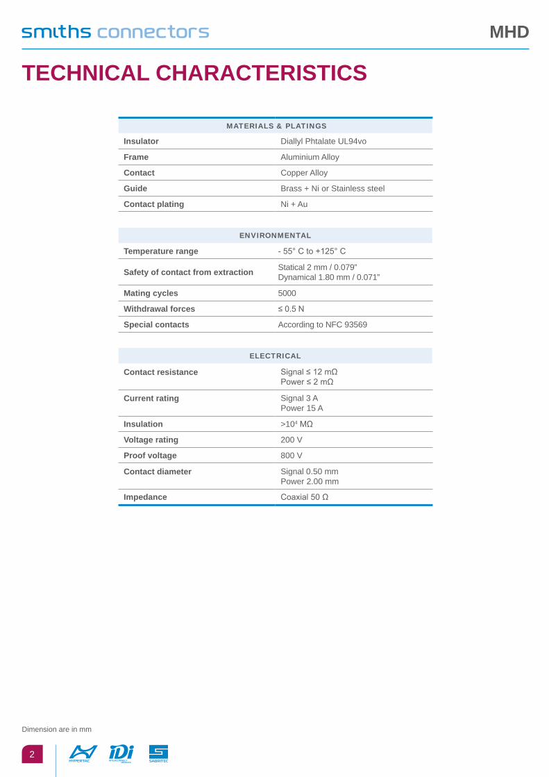
TECHNICAL CHARACTERISTICS
MATeriAls & plATings
Insulator Diallyl Phtalate UL94vo
Frame Aluminium Alloy
Contact Copper Alloy
Guide Brass + Ni or Stainless steel
Contact plating Ni + Au
environMenTAl
Temperature range - 55° C to +125° C
Safety of contact from extraction Statical 2 mm / 0.079”Dynamical 1.80 mm / 0.071”
Mating cycles 5000
Withdrawal forces ≤ 0.5 N
Special contacts According to NFC 93569
elecTricAl
Contact resistance Signal ≤ 12 mΩPower ≤ 2 mΩ
Current rating Signal 3 APower 15 A
Insulation >104 MΩ
Voltage rating 200 V
Proof voltage 800 V
Contact diameter Signal 0.50 mmPower 2.00 mm
Impedance Coaxial 50 Ω
Dimension are in mm

MHD
3
HOW TO ORDER
3401-065 01besA
HyperTAc MHD
1 2 3 4 5
1 series
2 ArrAngeMenT
0 5 2 1 5 2 2 5 2 3 5 2 5 HA 1 HB 6 XA
1 0 0 2 0 0 3 0 0 4 0 0 2 XA 7 XB 3 HB
3 pArT - polAriTy - plATing
1 3 5 5 Male Plug standard plating 2 2 4 4 Female Receptacle - Standard plating
1 7 5 7 Male Plug - Pretinned 2 6 4 6 Female Receptacle - Pretinned
4 TerMinATion sTyles
1 0 90° termination, PCB thickness 1.60 3 1 Straight termination, PCB thickness 3.20 4 4 SMT* - uncentered PCB thickness 3.80
1 1 90° termination, PCB thickness 2.40 4 1 SMT*- PCB thickness 1.60 4 5 SMT* - uncentered PCB thickness 1.60
1 2 90° termination, PCB thickness 3.20 4 2 SMT* - PCB thickness 3.20 4 7 SMT* - uncentered PCB thickness 2.40
3 0 Straight termination, PCB thickness 2.40 4 3 SMT* - PCB thickness 2.40 9 1 Female / male saver**
5 gUiDe sTyles
1 1 0 MALE POLARISED, TRANSVERSE MOUNT, STANDARD PLUG 1 1 1 MALE POLARISED, VERTICAL MOUNT
1 2 1 FEMALE POLARISED, VERTICAL MOUNT 1 2 2 FEMALE POLARISED, VERTICAL MOUNT
1 2 4 FEMALE POLARISED, TRANSVERSE MOUNT 1 2 5 MALE UNPOLARISED, TRANSVERSE MOUNT
1 2 6 FEMALE UNPOLARISED, VERTICAL MOUNT 1 3 0 FEMALE ALL POLARISED, VERTICAL MOUNT
1 3 1 FEMALE ALL POLARISED, VERTICAL MOUNT 1 3 3 FEMALE ALL POLARISED, TRANSVERSE MOUNT
1 3 4 FEMALE POLARISED, TRANSVERSE MOUNT 1 9 0 FEMALE POWER OR MASS CONTACT, VERTICAL MOUNT
1 9 1 MALE POWER OR MASS CONTACT, TRANSVERSE MOUNT 2 0 1 ¼ TURN, FREE CONNECTOR
* Surface Mount Termination ** Consult us - PCB thicknes is in mm
MHD
4
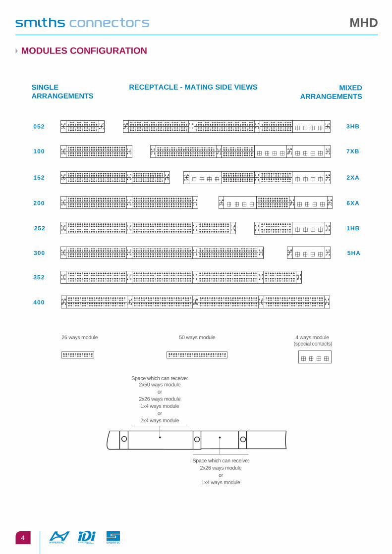
MODULES CONFIGURATION
SINGLE ARRANGEMENTS
RECEPTACLE - MATING SIDE VIEWS
26 ways module 50 ways module
052
100
152
200
252
352
400
300
4 ways module (special contacts)
Space which can receive:2x50 ways module
or2x26 ways module1x4 ways module
or2x4 ways module
Space which can receive:2x26 ways module
or1x4 ways module
3HB
7XB
2XA
6XA
1HB
5HA
MIXEDARRANGEMENTS
MHD
5
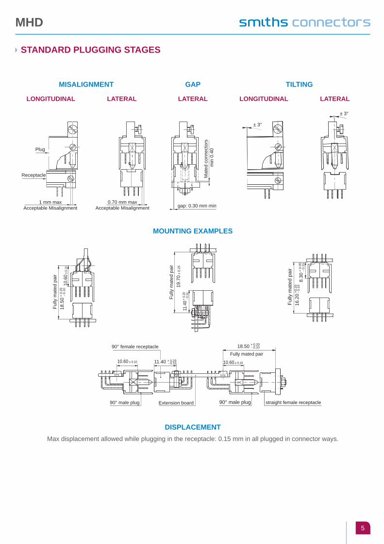
STANDARD PLUGGING STAGES
MISALIGNMENT
MOUNTING EXAMPLES
DISPLACEMENTMax displacement allowed while plugging in the receptacle: 0.15 mm in all plugged in connector ways.
TILTINGGAP
LONGITUDINAL LATERAL LATERAL LONGITUDINAL LATERAL
± 3°
± 3°
gap: 0.30 mm minM
ated
con
nect
ors
m
in 0
.40
0.70 mm maxAcceptable Misalignment
Plug
Receptacle
1 mm maxAcceptable Misalignment
- 0.
1018
.50 +
0.2
010
.60 ±
0.10
Fully
mat
ed p
air
19.7
0 ± 0.
25
Fully
mat
ed p
air
11.4
0 + 0
.20
- 0.1
0
Fully
mat
ed p
air
8.30
+ 0
.05
- 0.1
5
16.2
0- 0
.10
+0.2
0
+ 0.2090° female receptacle 18.50 - 0.10
11.40 + 0.20- 0.10 10.60 ± 0.1010.60 ± 0.10
90° male plug Extension board 90° male plug
Fully mated pair
straight female receptacle

MHD
6
TERMINATION STYLES
THROUGH BOARD SOLDER - 90°
THROUGH BOARD SOLDER - 90°
SURFACE MOUNT (CENTERED PCB)
THROUGH BOARD SOLDER - STRAIGHT
THROUGH BOARD SOLDER - STRAIGHT
SURFACE MOUNT (UNCENTERED PCB)
RECEPTACLE
PLUG
* Unbuild-up of tolerances
3.50
1.90
55.
715
1.90
5Ø
0.4
0
*2.65
A +0.15 - 0.45*
B
±0.05
Ref: 10PCb: 1.44 - 1.76A = 3.25B = 6 max
Ref: 11PCb: 1.98 - 2.42A = 3.85B = 6.60 max
+ 0.15- 0.45
+ 0.15- 0.45
Ref: 30PCb: 2.16 - 2.64A = 3.50 minA = 4.00 max
Ref: 31PCb: 2.88 - 5.50A = 6.10 minA = 6.60 max
Ref: 30PCb: 2.16 - 2.64A = 3.50 minA = 4.00 max
Ref: 31PCb: 2.88 - 3.52A = 4.60 minA = 5.10 max
Ref: 44PCb: 3.60 - 4.00A = 4.40 max
Ref: 45PCb: 1.44 - 1.76A = 7 max
Ref: 47PCb: 2.16 - 2.64A = 7 max
Ref: 10PCb: 1.44 - 1.76A = 5.95 max
Ref: 12PCb: 2.88 - 3.52A = 7.60 max
Ref: 41PCb: 1.44 - 1.76A = 5.20 max
Ref: 42PCb: 2.88 - 3.52A = 4.40 max
Ref: 43PCb: 2.16 - 2.64A = 4.80 max
Ø 0.401.905
2.54
1.905
A
A
3.50
1.90
55.
715
1.90
5Ø
0.40*2.65 ±0.05
12 max
* Unbuild-up of tolerances
Ø 0.40
A0.
50
12 max
A
Con
tact
poi
nt
5 m
ax
12 max
See
sec
tion
3.81
+0.2
5 - 0
.45
A 1.10 +0.15 - 0.10
Con
tact
poi
nt
5 m
ax
12 max
See
sec
tion
3.81
+0.2
5 - 0
.45
0.25
PC
B s
ide
0.35
Section

MHD
7
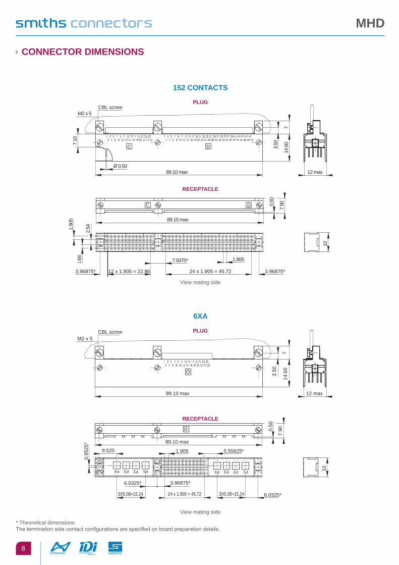
CONNECTOR DIMENSIONS
52 CONTACTS
100 CONTACTS
5HA
1HB
PLUG RECEPTACLE
3.50
14.6
0
CBL screw
M2 x 5
7.10
35.40 max 12 maxØ 0.50
7
MHD part number - Code date
F
3.96875* . 12x1.905=22.86 3.96875*
35.40 Max
0.50
7.90
1.905
1.90
5
2.54
1.90
5 10
FMHD part number - Code date
1.90
5
2.54
1.905
58.20 max
10
1.905
3.96875*3.96875* 24 x 1.905 = 45.72
0.50
7.90FMHD part number Code date
7.10
Ø 0.50
7
3.50
14.6
0
58.20 max 12 max
CBL screw
M2 x 5
MHD part number - Code date
F
View mating side
View mating side
View mating side
View mating side* Theoretical dimensions The termination side contact configurations are specified on board preparation details.
3.50
14.6
0
CBL screw
M2 x 5
7.10
35.40 max 12 max
7
MHD part number - Code date 12
3 4
AB
CD
P1P2P3P4
6.0325*3X5.08=15.249.525
35.40 max
0.50
0.95
25*
7.90
10
MHD part number - Code date
1.905
AB
CD
3X5.08=15.24
0.952
5*
12
3 4
P1P2P3P4 10
3.96875*3.96875*
5.55625*
12x1.905 = 22.86
58.20 max
0.50
7.90FMHD part number Code date
7.10
7
3.50
14.6
0
58.20 max 12 max
CBL screwM2 x 5
1 252 26
MHD part number Code date
D
MHD
8
CBL screwM2 x 5
7.10
3.50
14.6
0
12 max
7
Ø 0.50
C D
89.10 max
89.10 max
0.50
1.90
5
2.54
1.905
3.96875*3.96875* 12 x 1.905 = 22.86
7.9375*
24 x 1.905 = 45.72
7.90
1.905
10
C D
CONNECTOR DIMENSIONS
152 CONTACTS
PLUG
RECEPTACLE
6XA
View mating side
View mating side
* Theoretical dimensions The termination side contact configurations are specified on board preparation details.
89.10 max
1.905
AB
C D
12
3 4
P1P2P3P4 P1P2P3P4
5.55625*
3X5.08=15.24 3X5.08=15.24
9.525
.
0.95
25*
2625
2625
2
1
0.50
6.0325*
6.0325* 3.96875*
24 x 1.905 = 45.72
7.90
10
D
CBL screwM2 x 5
3.50
14.6
0
12 max
7
89.10 max
D
PLUG
RECEPTACLE
MHD
9
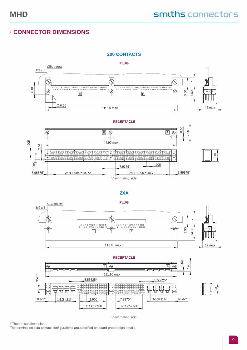
CONNECTOR DIMENSIONS
200 CONTACTS
2XA
View mating side
View mating side
* Theoretical dimensionsThe termination side contact configurations are specified on board preparation details.
3.50
7
M2 x 5
14.6
0
CBL screw
111.90 max 12 max
E F
6.0325*
P1P2P3P4
3X5.08=15.24
5.55625*
2625
2
1
2625
2625
5.55625*
6.0325*
P1P2P3P4
3X5.08=15.24.
0.95
25*
2625
1.905
111.90 max
7.900.
50
12 x 1.905 = 22.86
10
12 x 1.905 = 22.86
7.9375* .
FE
PLUG
PLUG
RECEPTACLE
RECEPTACLE

MHD
10
CONNECTOR DIMENSIONS
252 CONTACTS
7XB
View mating side
View mating side* Theoretical dimensions The termination side contact configurations are specified on board preparation details.
14.6
07
3.50
12 max
5048464442403836343230282624222018161412108642494745434139373533312927252321191715131197531
F
142.80 max
1 3 5 7 9 1113 15 17 1921 23 25 27 2931 33 35 37 39 41 43 45 47 492 4 6 8 10 12 14 16 18 20 22 24 26 28 30 32 34 36 38 4042 44 46 48 502624222018161412108642
252321191715131197531
ED
Ø 0.50
CBL screw M2 x 5
7.10
7.9375*
24 x 1.905 = 45.72
0.50
7.90
3.96875*
142.80 max
1.9053.96875*
12 x 1.905 = 22.86
1.90
51.
905
24 x 1.905 = 45.72
7.9375*
D E
2.54
F
10
E
14.6
07
3.50
12 max
5048464442403836343230282624222018161412108642494745434139373533312927252321191715131197531
F
142.80 max
CBL screw
M2 x 5
P1P2P3P4
3X5.08=15.24
6.0325* 6.0325*
P1P2P3P4
3X5.08=15.24
5.55625*9.525
0.95
25*
0.50
7.90
3.96875*
142.80 Max
1.905
1.90
51.
905
24 x 1.905 = 45.7212 x 1.905 = 22.86
7.9375*
D E
2.54
F
10
PLUG
PLUG
RECEPTACLE
RECEPTACLE
MHD
11
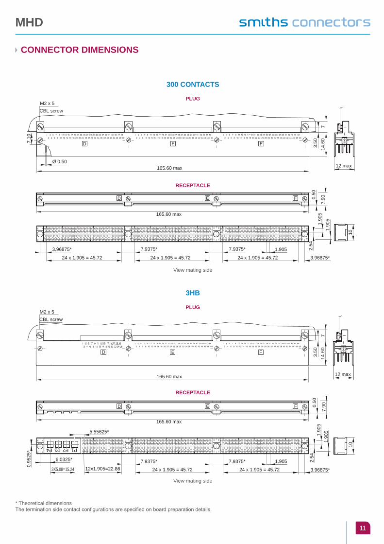
CONNECTOR DIMENSIONS
3HB
300 CONTACTS
View mating side
View mating side
12 max
14.6
07
3.50
CBL screw M2 x 5
7.10
165.60 max
0.50
7.90
1.90
51.
905
2.54
7.9375*
24 x 1.905 = 45.72
165.60 max
24 x 1.905 = 45.72
1.9053.96875*
24 x 1.905 = 45.72
7.9375*
3.96875*
10
Ø 0.50
12 max
D
14.6
07
3.50
CBL screw M2 x 5
165.60 max
P1P2P3P4
3X5.08=15.24
6.0325*
5.55625*
0.95
25*
7.900.
50
1.90
51.90
52.
54
7.9375*
24 x 1.905 = 45.72
165.60 max
12x1.905=22.861.905
24 x 1.905 = 45.72
7.9375*
3.96875*
10
PLUG
PLUG
RECEPTACLE
RECEPTACLE
* Theoretical dimensionsThe termination side contact configurations are specified on board preparation details.

MHD
12
CONNECTOR DIMENSIONS
352 CONTACTS 400 CONTACTS
View
mat
ing
side
View
mat
ing
side
12 m
ax
CBL screw M2 x 5
7.10
14.6073.50
196.
50 m
ax0.
50
HG
0.50
7.93
75*
10
24 x
1.9
05 =
45.
72
7.90
3.96
875*
196.
50 m
ax
1.90
5
3.96
875
*
12x1
.905
= 2
2.86
1.9051.905
2.54
24 x
1.9
05 =
45.
72
7.93
75*
7.93
75*
24 x
1.9
05 =
45.
72
12 m
ax
14.6073.50
219.
30 m
axØ
0.5
0
CBL screw M2 x 5 7.10
HG
10
0.50
7.90
1.90
5
3.96
875*
1.9051.905
2.54
24 x
1.9
05 =
45.
727.
9375
*24
x 1
.905
= 4
5.72
7.93
75*
24 x
1.9
05 =
45.
727.
9375
*24
x 1
.905
= 4
5.72
3.96
875*
219.
30 m
ax
PLUG PLUGRECEPTACLE RECEPTACLE
* Theoretical dimensions The termination side contact configurations are specified on board preparation details.
MHD
13
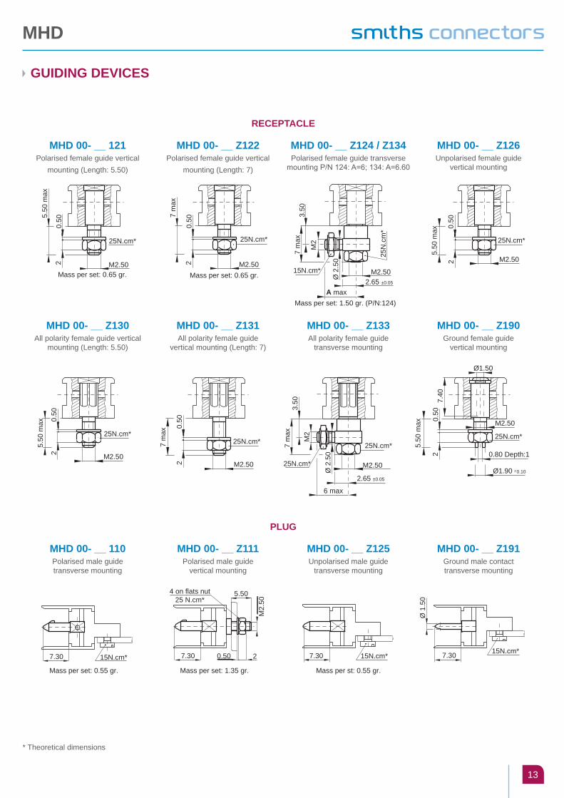
* Theoretical dimensions
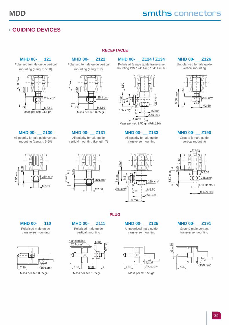
GUIDING DEVICES
RECEPTACLE
PLUG
MHD 00- __ 121Polarised female guide vertical
mounting (Length: 5.50)
MHD 00- __ 110Polarised male guide transverse mounting
MHD 00- __ Z130All polarity female guide vertical
mounting (Length: 5.50)
MHD 00- __ Z122Polarised female guide vertical
mounting (Length: 7)
MHD 00- __ Z111Polarised male guide
vertical mounting
MHD 00- __ Z131All polarity female guide
vertical mounting (Length: 7)
MHD 00- __ Z124 / Z134Polarised female guide transverse
mounting P/N 124: A=6; 134: A=6.60
MHD 00- __ Z125Unpolarised male guide
transverse mounting
MHD 00- __ Z133All polarity female guide
transverse mounting
MHD 00- __ Z126Unpolarised female guide
vertical mounting
MHD 00- __ Z191Ground male contact transverse mounting
MHD 00- __ Z190Ground female guide
vertical mounting
5.50
max
M2.5020.
50
25N.cm*
Mass per set: 0.65 gr.
7 m
ax
M2.5020.
50
25N.cm*
Mass per set: 0.65 gr.
A max
Ø 2
.50
M2
7 m
ax
M2.5015N.cm*
3.50
2.65 ±0.05
Mass per set: 1.50 gr. (P/N:124)
25N
.cm
*
5.50
max
M2.5020.
50
25N.cm*
0.50
2 M2.50
5.50
max
25N.cm*
0.50
2 M2.50
7 m
ax
25N.cm*
M2.50
7 m
ax
M2
Ø 2
.50
6 max
2.65 ±0.05
3.50
25N.cm*
25N.cm*
0.50
2
5.50
max
0.80 Depth:1
Ø1.90 -°0.10
7.40
Ø1.50
25N.cm*
M2.50.
Mass per set: 0.55 gr.
15N.cm*7.30
Mass per set: 1.35 gr.
.7.30 0.50 2
M2.
50
5.504 on flats nut25 N.cm*
Mass per st: 0.55 gr.
15N.cm*7.3015N.cm*7.30
Ø 1
.50

MHD
14
52 CONTACT BOARD PREPARATION DETAILS (1)
STRAIGHT TERMINATION Guides: 121, 122, 126, 130, 131, 190
STRAIGHT TERMINATION Guides: 111
SURFACE MOUNT TERMINATION Guides: 110, 125, 191
90° TERMINATION Guides: 124, 133, 134
90° TERMINATION Guides: 110, 125, 191
3.96875* 12 x 1.905 = 22.86 3.96875*
1.905
2 ho
les
min
Ø 2
.70
30.7975*
1.90
51.
905
1.27
1.27
52 holes min Ø 0.55
30.7975 *
1.90
5
3.96875*
2 ho
les
min
2.7
0 12 x 1.905 = 22.86 3.96875*
1.905
2.40
2.80
2.40
5.71
51.
9052.
80 52 holes min Ø 0.55
2 ho
les
min
Ø2.
70
52 holesmin Ø 0.55
30.7975*
1.90
51.
905
3.4925* 25 x 0.9525 = 23.8125* 3.4925*
1.9050.9525*
1.27
1.27
30.7975 *
1.90
5
5.71
51.
905
3.4925*
2.80
25 x 0.9525 = 23.8125* 3.4925*
1.9050.9525*
2.402.402.
80
52 holes min Ø 0.55
2 ho
les
min
Ø 2
.10
H view G view
Axis of tracks
0.9525*
3.4925*3.4925*
23.8125*
3.4925*
3.81
(con
tact
poi
nt)
2.80
2.402.40
23.8125 *
30.7975*
3.4925*
2.80
2 holes min Ø 2.10
G H
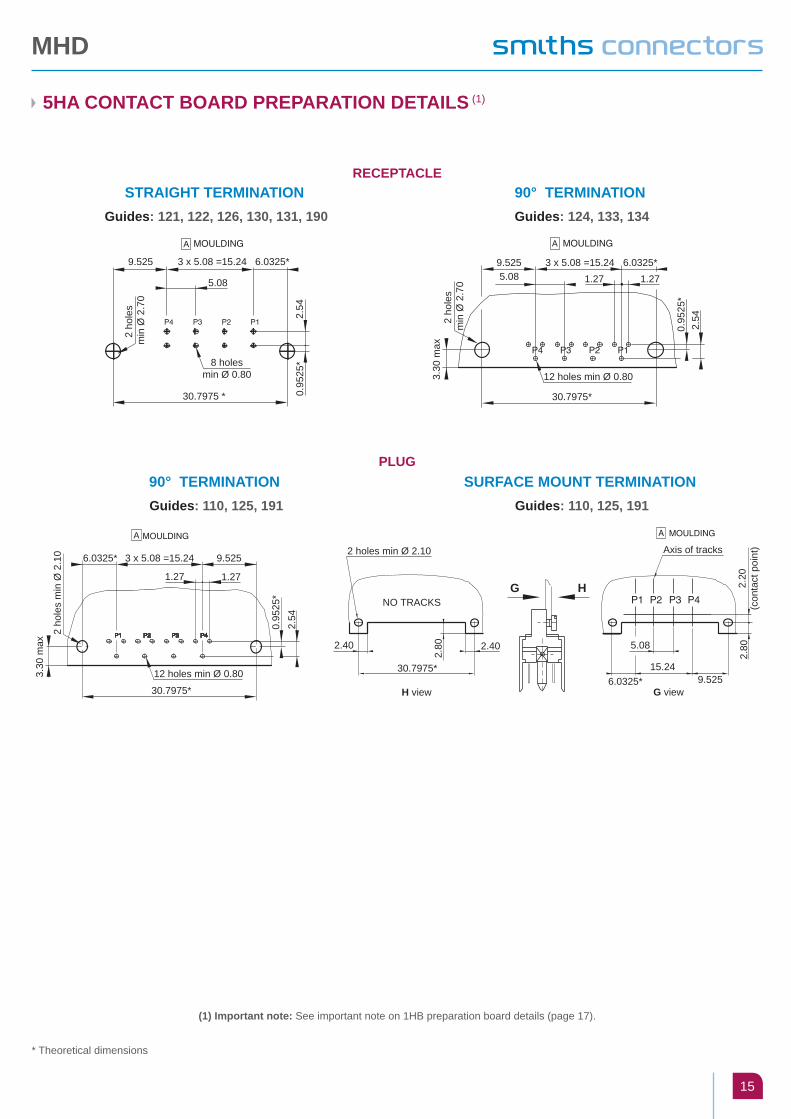
* Theoretical dimensions
(1) Important note: See important note on 1HB preparation board details (page 17).
PLUG
RECEPTACLE
MHD
15
5HA CONTACT BOARD PREPARATION DETAILS (1)
STRAIGHT TERMINATION Guides: 121, 122, 126, 130, 131, 190
90° TERMINATION Guides: 110, 125, 191
90° TERMINATION Guides: 124, 133, 134
SURFACE MOUNT TERMINATION Guides: 110, 125, 191
5.08
6.0325*3 x 5.08 =15.249.525
2.54
0.95
25*
30.7975 *
2 ho
les
min
Ø 2
.70
8 holesmin Ø 0.80 3.
30 m
ax
1.276.0325*3 x 5.08 =15.249.525
0.95
25*
30.7975*
2.54
1.275.08
2 ho
les
min
Ø 2
.70
12 holes min Ø 0.80
3.30
max
9.5253 x 5.08 =15.246.0325*
2.54
0.95
25*
30.7975*
1.271.27
2 ho
les
min
Ø 2
.10
12 holes min Ø 0.80
G view H view
5.08
Axis of tracks
2.40
G H
2.40
30.7975*6.0325*
15.249.525
2.20
(con
tact
poi
nt)
2.80
2.80
NO TRACKS
2 holes min Ø 2.10
* Theoretical dimensions
(1) Important note: See important note on 1HB preparation board details (page 17).
PLUG
RECEPTACLE

MHD
16
100 CONTACT BOARD PREPARATION DETAILS (1)
STRAIGHT TERMINATION Guides: 121, 122, 126, 130, 131, 190
STRAIGHT TERMINATION Guides: 111
SURFACE MOUNT TERMINATION Guides: 110, 125, 191
90° TERMINATION Guides: 124, 133, 134
90° TERMINATION Guides: 110, 125, 191
50 48
49 47
1 3
2 4 48
47 49
50
3
4
1
2
1.27
1.27
1.905
3.96875*3.96875*
1.90
51.
905
53.6575*
24 x 1.905 = 45.72
2 ho
les
min
Ø 2
.70
100 holes min Ø 0.55
5.71
5
2.40
2.80
2.40
1.905
3.96875*24 x 1.905 = 45.723.96875*
1.90
5
1.90
5
53.6575*2.80
2 ho
les
min
Ø 2
.70
100 holes min Ø 0.55
A MOULDING A MOULDING
F MOULDING F MOULDING
1.27
1.27
0.9525* 1.905
3.4925*3.4925*
1.90
51.
905
53.6575*
49 x 0.9525 = 46.6725*
100 holesmin Ø 0.552
hole
s m
in Ø
2.7
0
2.40 2.40
0.9525* 1.905
3.4925*49 x 0.9525 = 46.6725*3.4925*
53.6575 *
2.80
2.80
1.90
55.
715
1.90
5
100 holesmin Ø 0.55
2 ho
les
min
Ø 2
.10
A MOULDING A MOULDING
F MOULDING F MOULDING
2.40
H view G view
53.6575*
2.40
46.6725*
2.80
Axis of tracks
46.6725*
0.9525*3.81
(C
onta
ct p
oint
)
2 holes min Ø 2.10
G H
3.4925* 3.4925*
F MOULDING A MOULDING
* Theoretical dimensions
PLUG
RECEPTACLE
(1) Important note: See important note on 1HB preparation board details (page 17).
MHD
17
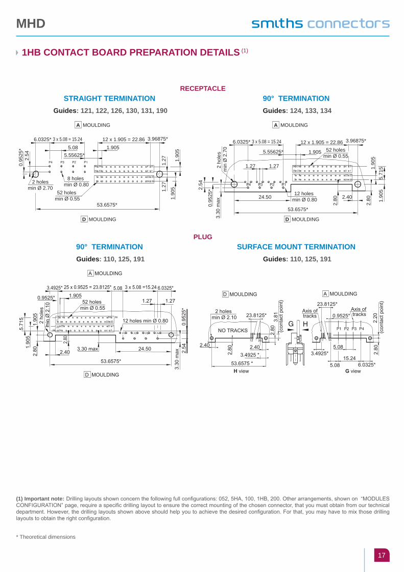
1HB CONTACT BOARD PREPARATION DETAILS (1)
STRAIGHT TERMINATION Guides: 121, 122, 126, 130, 131, 190
90° TERMINATION Guides: 110, 125, 191
90° TERMINATION Guides: 124, 133, 134
SURFACE MOUNT TERMINATION Guides: 110, 125, 191
(1) Important note: Drilling layouts shown concern the following full configurations: 052, 5HA, 100, 1Hb, 200. Other arrangements, shown on “MODULES CONFIGURATION” page, require a specific drilling layout to ensure the correct mounting of the chosen connector, that you must obtain from our technical department. However, the drilling layouts shown above should help you to achieve the desired configuration. For that, you may have to mix those drilling layouts to obtain the right configuration.
* Theoretical dimensions
5.086.0325* 3 x 5.08 = 15.24
2.54
0.95
25* 1.905
12 x 1.905 = 22.86
1.27
1.27 1.
905
1.90
5
3.96875*
5.55625*
53.6575*
52 holes min Ø 0.55
8 holes min Ø 0.802 holes
min Ø 2.70
5.71
5
2.40
1.90
51.
905
53.6575*
1.905
3.96875*12 x 1.905 = 22.8652 holes
min Ø 0.555.55625*
3.30
max
6.0325* 3 x 5.08 = 15.24
24.50
2.80
2.80
2.54
0.95
25*
1.271.272 ho
les
min
Ø 2
.70
12 holes min Ø 0.80
A MOULDINGA MOULDING
D MOULDING D MOULDING
PLUG
RECEPTACLE
MHD
18
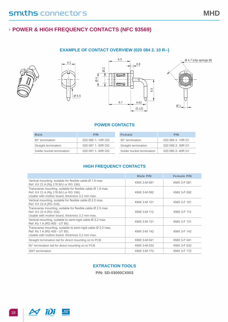
POWER & HIGH FREqUENCY CONTACTS (NFC 93569)
EXAMPLE OF CONTACT OVERVIEW (020 084 2. 10 R--)
POWER CONTACTS
HIGH FREqUENCY CONTACTS
EXTRACTION TOOLSP/N: SD-03000CX003
4.16.5
6.7 4.62
(5.12)
Ø 2
Ø 4
6.5
0.8Ø 4.7 (clip springs Ø)
Ø 5.5
Ø 1
Male p/n Female p/n
90° termination 020 085 1- 10R OG 90° termination 020 084 2- 10R G1
Straight termination 020 087 1- 30R OG Straight termination 020 056 2- 30R G1
Solder bucket termination 020 091 1- 40R OG Solder bucket termination 020 060 2- 40R G1
Male p/n Female p/n
Vertical mounting, suitable for flexible cable Ø 1.9 max. Ref. KX 21 A (Rg 178 B/U or RG 196). KMX 3-M 081 KMX 3-F 081
Transverse mounting, suitable for flexible cable Ø 1.9 max. Ref. KX 21 A (Rg 178 B/U or RG 196). Usable with mother board, thickness 3.2 mm max.
KMX 3-M 092 KMX 3-F 092
Vertical mounting, suitable for flexible cable Ø 2.5 max. Ref. KX 22 A (RG 316). KMX 3-M 101 KMX 3-F 101
Transverse mounting, suitable for flexible cable Ø 2.5 max.Ref. KX 22 A (RG 316).Usable with mother board, thickness 3.2 mm max.
KMX 3-M 112 KMX 3-F 112
Vertical mounting, suitable to semi-rigid cable Ø 2.2 max.Ref. Ks 1 A (RG 405 - UT 85). KMX 3-M 131 KMX 3-F 131
Transverse mounting, suitable to semi-rigid cable Ø 2.2 max.Ref. Ks 1 A (RG 405 - UT 85).Usable with mother board, thickness 3.2 mm max.
KMX 3-M 142 KMX 3-F 142
Straight termination tail for direct mounting on to PCB KMX 3-M 041 KMX 3-F 041
90° termination tail for direct mounting on to PCB KMX 3-M 032 KMX 3-F 032
SMT termination KMX 3-M 172 KMX 3-F 172

MDD
19
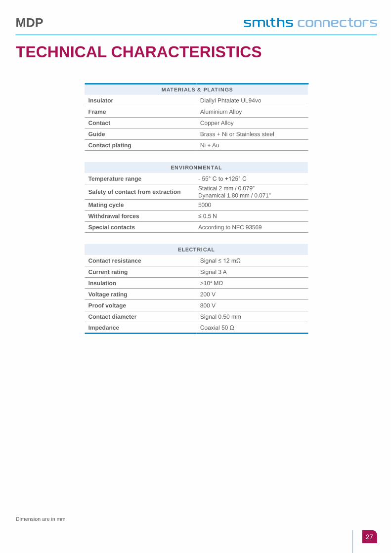
TECHNICAL CHARACTERISTICS
MATeriAls & plATings
Insulator Diallyl Phtalate UL94vo
Frame Aluminium Alloy
Contact Copper Alloy
Guide Brass + Ni or Stainless steel
Contact plating Ni + Au
environMenTAl
Temperature range - 55° C to +125° C
Safety of contact from extraction Statical 2 mm / 0.079”Dynamical 1.80 mm / 0.071”
Mating cycles 5000
Withdrawal forces ≤ 0.5 N
Special contacts According to NFC 93569
elecTricAl
Contact resistance Signal ≤ 12 mΩ
Current rating Signal 3 A
Insulation >104 MΩ
Voltage rating 200 V
Proof voltage 800 V
Contact diameter Signal 0.50 mm
Impedance Coaxial 50 Ω
Dimension are in mm

MDD
20
HOW TO ORDER
MD D 1 2 3 4 5
1 series
2 ArrAngeMenT
1 0 0 2 0 0
3 pArT - polAriTy - plATing
1 5 Male Plug - MIL plating 2 4 Female Receptacle - MIL plating
1 9 Male Plug - MIL tinned plating 2 8 Female Receptacle - MIL tinned plating
4 TerMinATion sTyles
1 0 90° termination, PCB thickness 1.60 3 0 Straight termination, PCB thickness 2.40 4 4 SMT* - uncentered PCB thickness 3.80
1 1 90° termination, PCB thickness 2.40 3 1 Straight termination, PCB thickness 3.20 9 6 Straight termination, PCB thickness 4.50
5 gUiDe sTyles
1 1 0 MALE POLARISED, TRANSVERSE MOUNT, STANDARD PLUG 1 1 1 MALE POLARISED, VERTICAL MOUNT
1 2 1 FEMALE POLARISED, VERTICAL MOUNT 1 2 2 FEMALE POLARISED, VERTICAL MOUNT
1 2 4 FEMALE POLARISED, TRANSVERSE MOUNT 1 2 5 MALE UNPOLARISED, TRANSVERSE MOUNT
1 2 6 FEMALE UNPOLARISED, VERTICAL MOUNT 1 3 0 FEMALE ALL POLARISED, VERTICAL MOUNT
1 3 1 FEMALE ALL POLARISED, VERTICAL MOUNT 1 3 3 FEMALE ALL POLARISED, TRANSVERSE MOUNT
1 3 4 FEMALE POLARISED, TRANSVERSE MOUNT 1 9 0 FEMALE POWER OR MASS CONTACT, VERTICAL MOUNT
1 9 1 MALE POWER OR MASS CONTACT, TRANSVERSE MOUNT 2 0 1 ¼ TURN, FREE CONNECTOR
* Surface Mount Termination PCB thickness is in mm

MDD
21
MODULES CONFIGURATION
RECEPTACLE - MATING SIDE VIEWS
SINGLE ARRANGEMENTS
100
50 ways module
200

MDD
22
STANDARD PLUGGING STAGES
MISALIGNMENT
MOUNTING EXAMPLES
DISPLACEMENTMax displacement allowed while plugging in the receptacle: 0.15 mm in all plugged in connector ways.
TILTINGGAP
LONGITUDINAL LATERAL LATERAL LONGITUDINAL LATERAL
± 3°
± 3°
gap: 0.30 mm minM
ated
con
nect
ors
m
in 0
.40
0.70 mm maxAcceptable Misalignment
Plug
Receptacle
1 mm maxAcceptable Misalignment
- 0.
1018
.50 +
0.2
010
.60 ±
0.10
Fully
mat
ed p
air
19.7
0 ± 0.
25
Fully
mat
ed p
air
11.4
0 + 0
.20
- 0.1
0
Fully
mat
ed p
air
8.30
+ 0
.05
- 0.1
5
16.2
0- 0
.10
+0.2
0
+ 0.2090° female receptacle 18.50 - 0.10
11.40 + 0.20- 0.10 10.60 ± 0.1010.60 ± 0.10
90° male plug Extension board 90° male plug
Fully mated pair
straight female receptacle
MDD
23
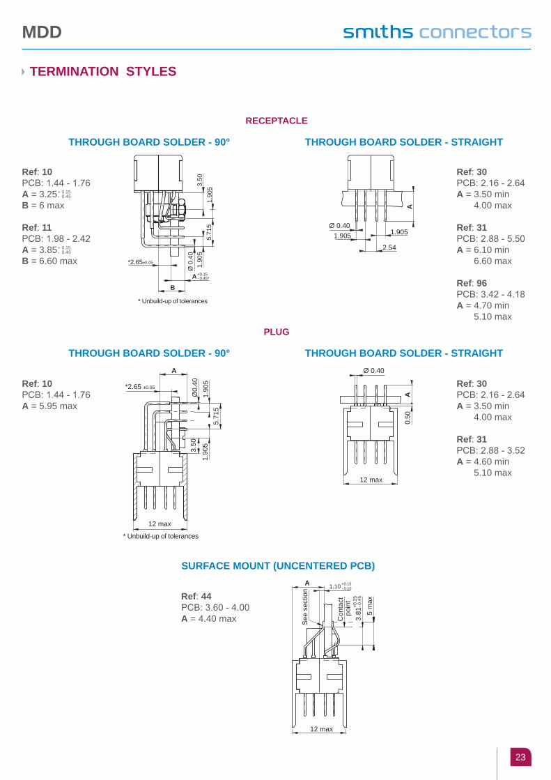
TERMINATION STYLES
THROUGH BOARD SOLDER - 90°
THROUGH BOARD SOLDER - 90°
THROUGH BOARD SOLDER - STRAIGHT
THROUGH BOARD SOLDER - STRAIGHT
RECEPTACLE
PLUG
* Unbuild-up of tolerances
3.50
1.90
55.
715
1.90
5Ø
0.4
0
*2.65
A +0.15 - 0.45*
B
±0.05
Ref: 10PCb: 1.44 - 1.76A = 3.25B = 6 max
Ref: 11PCb: 1.98 - 2.42A = 3.85B = 6.60 max
+ 0.15- 0.45
+ 0.15- 0.45
Ref: 30PCb: 2.16 - 2.64A = 3.50 minA = 4.00 max
Ref: 31PCb: 2.88 - 5.50A = 6.10 minA = 6.60 max
Ref: 96PCb: 3.42 - 4.18A = 4.70 minA = 5.10 max
Ref: 30PCb: 2.16 - 2.64A = 3.50 minA = 4.00 max
Ref: 31PCb: 2.88 - 3.52A = 4.60 minA = 5.10 max
Ref: 10PCb: 1.44 - 1.76A = 5.95 max
Ø 0.401.905
2.54
1.905
A
A
3.50
1.90
55.
715
1.90
5Ø
0.40*2.65 ±0.05
12 max
* Unbuild-up of tolerances
Ø 0.40
A0.
50
12 max
SURFACE MOUNT (UNCENTERED PCB)
Ref: 44PCb: 3.60 - 4.00A = 4.40 max
A 1.10 +0.15 - 0.10
Con
tact
poi
nt
5 m
ax
12 max
See
sec
tion
3.81
+0.2
5 - 0
.45
MDD
24
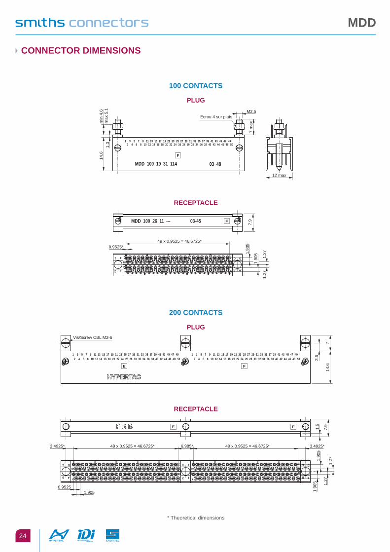
CONNECTOR DIMENSIONS
100 CONTACTS
200 CONTACTS
* Theoretical dimensions
1 3 5 7 9 11 13 15 17 19 21 23 25 27 29 31 33 35 37 39 41 43 45 47 492 4 6 8 10 12 14 16 18 20 22 24 26 28 30 32 34 36 38 40 42 44 46 48 50
F
MDD 100 19 31 114 03 48
12 max
Ecrou 4 sur platsM2.5
14.6
7 m
ax
1.3
min
4.6
max
5.1
49 x 0.9525 = 46.6725*0.9525*
7.9
1.90
5
1.90
5 1.27
1.27
MDD 100 26 11 --- 03-45
12
12
49 AB
C D49
12
3 4
F
1 3 5 7 9 11 13 15 17 19 21 23 25 27 29 31 33 35 37 39 41 43 45 47 49 1 3 5 7 9 11 13 15 17 19 21 23 25 27 29 31 33 35 37 39 41 43 45 47 49
F
Vis/Screw CBL M2-6
3.5
14.6
7
E
2 4 6 8 10 12 14 16 18 20 22 24 26 28 30 32 34 36 38 40 42 44 46 48 50 2 4 6 8 10 12 14 16 18 20 22 24 26 28 30 32 34 36 38 40 42 44 46 48 50
F
49 x 0.9525 = 46.6725*3.4925*
0.95251.905
3.4925*6.985* 49 x 0.9525 = 46.6725*
1.5
7.9
1.90
51.
905
1.27
1.27
E
12
1
2
49
AB
C D
AB
C D
49
12
4912
49
12
3 4
PLUG
PLUG
RECEPTACLE
RECEPTACLE
MDD
25
GUIDING DEVICES
RECEPTACLE
PLUG
MHD 00- __ 121Polarised female guide vertical
mounting (Length: 5.50)
MHD 00- __ 110Polarised male guide transverse mounting
MHD 00- __ Z130All polarity female guide vertical
mounting (Length: 5.50)
MHD 00- __ Z122Polarised female guide vertical
mounting (Length: 7)
MHD 00- __ Z111Polarised male guide
vertical mounting
MHD 00- __ Z131All polarity female guide
vertical mounting (Length: 7)
MHD 00- __ Z124 / Z134Polarised female guide transverse
mounting P/N 124: A=6; 134: A=6.60
MHD 00- __ Z125Unpolarised male guide
transverse mounting
MHD 00- __ Z133All polarity female guide
transverse mounting
MHD 00- __ Z126Unpolarised female guide
vertical mounting
MHD 00- __ Z191Ground male contact transverse mounting
MHD 00- __ Z190Ground female guide
vertical mounting
5.50
max
M2.5020.
50
25N.cm*
Mass per set: 0.65 gr.
7 m
ax
M2.5020.
50
25N.cm*
Mass per set: 0.65 gr.
A max
Ø 2
.50
M2
7 m
ax
M2.5015N.cm*
3.50
2.65 ±0.05
Mass per set: 1.50 gr. (P/N:124)
25N
.cm
*
5.50
max
M2.5020.
50
25N.cm*
0.50
2 M2.50
5.50
max
25N.cm*
0.50
2 M2.50
7 m
ax
25N.cm*
M2.50
7 m
ax
M2
Ø 2
.50
6 max
2.65 ±0.05
3.50
25N.cm*
25N.cm*
0.50
2
5.50
max
0.80 Depth:1
Ø1.90 -°0.10
7.40
Ø1.50
25N.cm*
M2.50.
Mass per set: 0.55 gr.
15N.cm*7.30
Mass per set: 1.35 gr.
.7.30 0.50 2
M2.
50
5.504 on flats nut25 N.cm*
Mass per st: 0.55 gr.
15N.cm*7.3015N.cm*7.30
Ø 1
.50
MDD
26
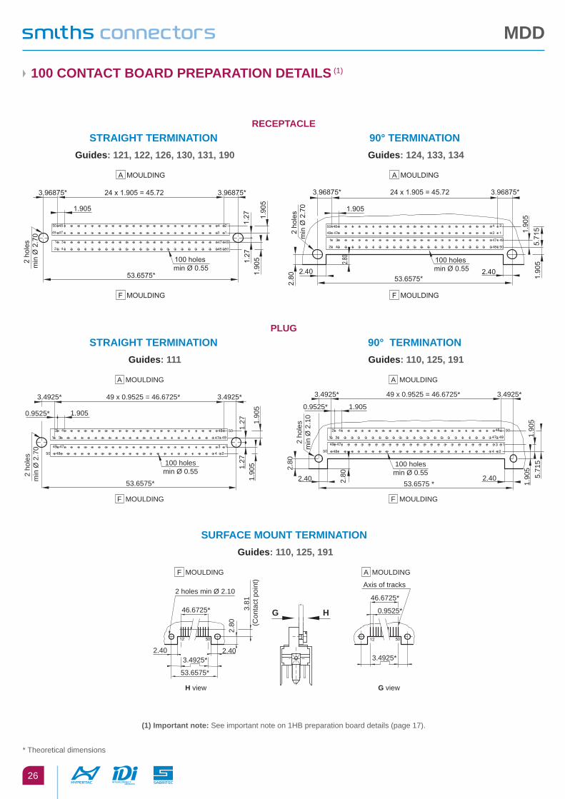
100 CONTACT BOARD PREPARATION DETAILS (1)
STRAIGHT TERMINATION Guides: 121, 122, 126, 130, 131, 190
STRAIGHT TERMINATION Guides: 111
SURFACE MOUNT TERMINATION Guides: 110, 125, 191
90° TERMINATION Guides: 124, 133, 134
90° TERMINATION Guides: 110, 125, 191
50 48
49 47
1 3
2 4 48
47 49
50
3
4
1
2
1.27
1.27
1.905
3.96875*3.96875*
1.90
51.
905
53.6575*
24 x 1.905 = 45.72
2 ho
les
min
Ø 2
.70
100 holes min Ø 0.55
5.71
5
2.40
2.80
2.40
1.905
3.96875*24 x 1.905 = 45.723.96875*
1.90
5
1.90
5
53.6575*2.80
2 ho
les
min
Ø 2
.70
100 holes min Ø 0.55
A MOULDING A MOULDING
F MOULDING F MOULDING
1.27
1.27
0.9525* 1.905
3.4925*3.4925*
1.90
51.
905
53.6575*
49 x 0.9525 = 46.6725*
100 holesmin Ø 0.552
hole
s m
in Ø
2.7
0
2.40 2.40
0.9525* 1.905
3.4925*49 x 0.9525 = 46.6725*3.4925*
53.6575 *
2.80
2.80
1.90
55.
715
1.90
5
100 holesmin Ø 0.55
2 ho
les
min
Ø 2
.10
A MOULDING A MOULDING
F MOULDING F MOULDING
2.40
H view G view
53.6575*
2.40
46.6725*
2.80
Axis of tracks
46.6725*
0.9525*3.81
(C
onta
ct p
oint
)
2 holes min Ø 2.10
G H
3.4925* 3.4925*
F MOULDING A MOULDING
PLUG
RECEPTACLE
* Theoretical dimensions
(1) Important note: See important note on 1HB preparation board details (page 17).
MDP
27
TECHNICAL CHARACTERISTICS
MATeriAls & plATings
Insulator Diallyl Phtalate UL94vo
Frame Aluminium Alloy
Contact Copper Alloy
Guide Brass + Ni or Stainless steel
Contact plating Ni + Au
environMenTAl
Temperature range - 55° C to +125° C
Safety of contact from extraction Statical 2 mm / 0.079”Dynamical 1.80 mm / 0.071”
Mating cycle 5000
Withdrawal forces ≤ 0.5 N
Special contacts According to NFC 93569
elecTricAl
Contact resistance Signal ≤ 12 mΩ
Current rating Signal 3 A
Insulation >104 MΩ
Voltage rating 200 V
Proof voltage 800 V
Contact diameter Signal 0.50 mm
Impedance Coaxial 50 Ω
Dimension are in mm
MDP
28
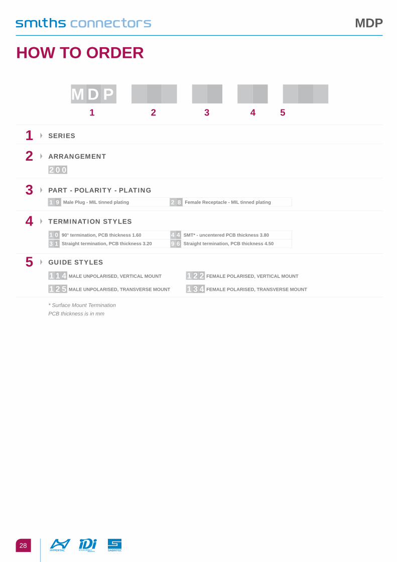
HOW TO ORDER
MD p 1 2 3 4 5
1 series
2 ArrAngeMenT
2 0 0
3 pArT - polAriTy - plATing
1 9 Male Plug - MIL tinned plating 2 8 Female Receptacle - MIL tinned plating
4 TerMinATion sTyles
1 0 90° termination, PCB thickness 1.60 4 4 SMT* - uncentered PCB thickness 3.80
3 1 Straight termination, PCB thickness 3.20 9 6 Straight termination, PCB thickness 4.50
5 gUiDe sTyles
1 1 4 MALE UNPOLARISED, VERTICAL MOUNT 1 2 2 FEMALE POLARISED, VERTICAL MOUNT
1 2 5 MALE UNPOLARISED, TRANSVERSE MOUNT 1 3 4 FEMALE POLARISED, TRANSVERSE MOUNT
* Surface Mount Termination PCB thickness is in mm
MDP
29
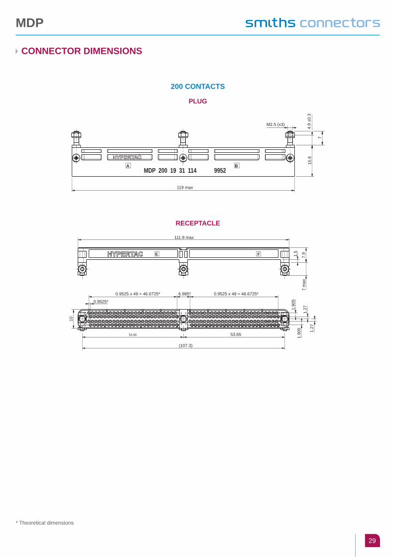
CONNECTOR DIMENSIONS
200 CONTACTS
PLUG
RECEPTACLE
119 max
M2.5 (x3)
4.9
±0.3
7
15.9
MDP 200 19 31 114 9952A B
0.9525 x 49 = 46.6725* 0.9525 x 49 = 46.6725*6.985*
0.9525*
53.65
(107.3)
53.65
111.9 max
10
1.90
51.
905
1.27
1.27
1.5
7.9
7 m
ax
E
2
49
AB
C D
F
2
2
12
43
49
49
2
49 AB
C D
* Theoretical dimensions
MDP
30
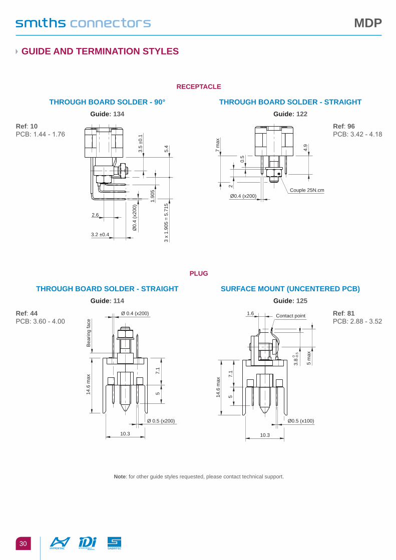
GUIDE AND TERMINATION STYLES
THROUGH BOARD SOLDER - 90°Guide: 134
SURFACE MOUNT (UNCENTERED PCB)Guide: 125
THROUGH BOARD SOLDER - STRAIGHTGuide: 122
THROUGH BOARD SOLDER - STRAIGHTGuide: 114
RECEPTACLE
PLUG
3.2 ±0.4
2.6
3 x
1.90
5 =
5.71
5
1.90
5
5.4
Ø0.
4 (x
200)
3.5
±0.1
Ref: 10PCb: 1.44 - 1.76
Ref: 96PCb: 3.42 - 4.18
Ref: 81PCb: 2.88 - 3.52
Ref: 44PCb: 3.60 - 4.00
Couple 25N.cmØ0.4 (x200)
7 m
ax
0.5
4.9
2
Ø 0.4 (x200)
Ø 0.5 (x200)
10.3
Bea
ring
face
14.6
max
7.1
5
Contact point1.6
10.3
Ø0.5 (x100)
3.8 0 -0
.5
5 m
ax
14.6
max
7.1
5
Note: for other guide styles requested, please contact technical support.

MDP
200 CONTACT BOARD PREPARATION DETAILS
STRAIGHT TERMINATION Guide: 122
STRAIGHT TERMINATION Guide: 114
90° TERMINATION Guide: 184
SURFACE MOUNT TERMINATION Guide: 125
200 holes Ø0.55 min3 holes ØA B
45.7245.72
3.96875*
107.315*
3.96875*
3.96875*3.96875*
1.905
1.90
51.
905
2.54
MouldingMoulding
1.27
1.27
B
50 48
49
1
2 4 5048
49
1
2 50 48
49
1
2 4 48 50
49
1
244
A
MouldingMouldingE F
3 holes Ø
2.7 min
200 holesØ
0.55 min
107.315
2.40
Moulding
1.905
3.96875* 3.96875*
3.96875* 3.96875*
24 x 1.905 = 45.72
53.6575* 53.6575*
24 x 1.905 = 45.72
B AMoulding
MouldingE MouldingF
A A A2.40
A
2.80
1.905
1.9055.715
A
2.40 2.40
2.80A
107.315*
53.6575*
3.4925*
3.4925*
200 holes Ø
0.55 min
3 holes ØA
0.9525* 0.9525*1.905
46.6725* 46.6725* 3.4925*
3.4925*
53.6575*
Moulding B
2
1 3 47 4
4
49 47 3 1
50 1 248
48 50
Moulding A
Moulding EMoulding F
2
1 3 47 4
4
49 47 3 1
50 1 248
48 50
1.905
107.315
3.4925*3.4925*
2.4
3 holes Ø2.1 min
3.81
(poi
nt o
f con
tact
)
46.6725* 46.6725*
2.4 2.4 2.4
2.8
3.4925* 3.4925*3.4925*
0.9525*46.6725* 46.6725*
3.4925* 3.4925* 3.4925*
H view G view
Moulding F
G H
Moulding BMoulding AMoulding
See detail A
E
2 501 2 50 5021 50211
PLUG
RECEPTACLE


