

MiCAT PlannerChanging the relationship between
people and precision measurement with one click

Three Letter Acronyms (TLAs)• MBD is Model Based Definition
• MBM is Model Based Manufacturing
• MBI is Model Based Inspection
• PMI is Product & Manufacturing Information
• DME is Dimensional Measurement Equipment

Defining MBDs• MBDs include PMI, which are visible
dimensions, tolerances, notes, text, or symbols
• MBDs are created by Design Engineering but used by Manufacturing & Inspection
• MBD standards include ASME Y14.41-2012 Digital Product Definition Data Practices and Mil-Std-31000A Technical Data Package

MBDs & two kinds of PMI
• Presentation PMI• Visualizes PMI for the person• Essentially creates a 3D drawing• It may be organized by views in the CAD software
• Representation PMI• Complements Presentation PMI• Also known as ‘Semantic’ PMI• Enables Model Based Inspection
Joshua Lubell at NIST notes: “Unambiguous representation and presentation of PMI are critical for digital product definition”
Ref: Lubell, J. “PMI Validation and Conformance Testing for Model-based Engineering” NIST Systems Engineering Conference in Washington DC (SEDC) April 3, 2014

The MBD Journey• Drawing Based workflow, where the 2D Drawing is
the Master
• Model Centric workflow, where the 2D Drawing is the Master and the 3D Model provides part geometry
• Model Based Definition Workflow, where the 3D Model with PMI is the Master
To assess your company’s model based capability:
http://model-based-enterprise.org/mbe-assessment-tool.html

MBDs & Supplemental Geometry• Supplemental geometry communicates design
requirements but is not intended to represent a real part feature
• Some examples of supplemental geometry are
- Center Lines
- Center Planes
- Datum Targets
- Bolt Circles

Questions before we proceed?
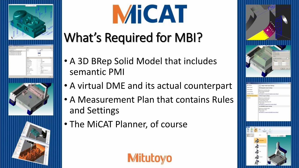
What’s Required for MBI?
• A 3D BRep Solid Model that includes semantic PMI
• A virtual DME and its actual counterpart
• A Measurement Plan that contains Rules and Settings
• The MiCAT Planner, of course

Dimensional Measuring Equipment• Model Based Inspection is used often
with CNC DMEs
• The most common CNC DME is the Coordinate Measurement Machine (aka CMM)
• Most current and new Mitutoyo CNC CMMs support MBI when used with the MiCAT Planner
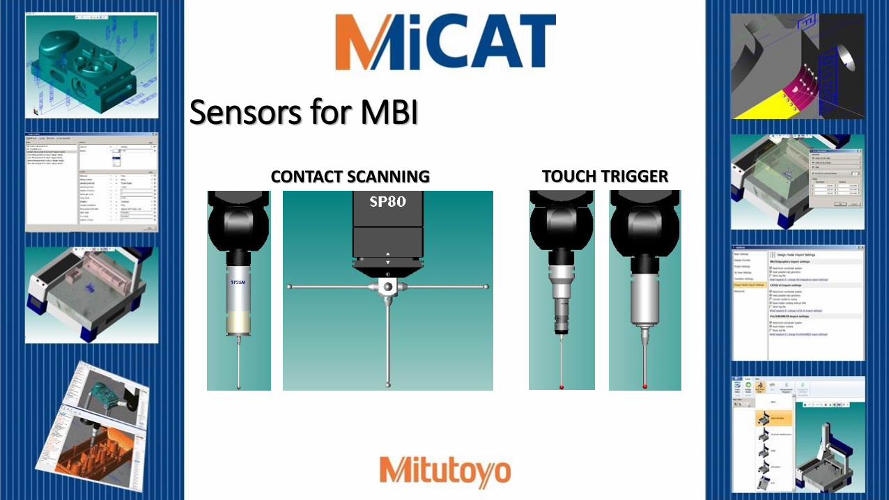
Sensors for MBI
TOUCH TRIGGERCONTACT SCANNING

CMMs for MBI
BRIDGEShop Hardened
GANTRY
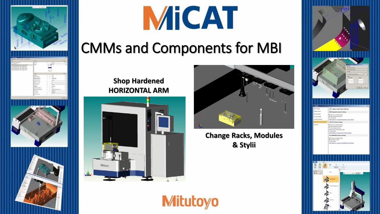
CMMs and Components for MBI
Change Racks, Modules& Stylii
Shop Hardened HORIZONTAL ARM

Questions before we proceed?
Virtual Legex CMM Actual Legex CMM

What is MiCAT Planner?
It is a measurement program software from Mitutoyo that enables one-click automated generation of CNC CMM programs.
MiCAT Planner makes model based inspection a practical and worthwhile reality.

Upstream of MiCAT Planner
• Activities upstream of the MiCAT Planner MBI solution include
• 3D Modeling • 3D Model Annotation • Model Based Procedures• MBD Validation • Best Practice MBI Rules

The MiCAT Planner MBI Work Flow
User
Parameter
Settings
User
Defined
Rules
Defaults
&
Intelligence
MBD
Configured virtual CMM (DME)
MiCAT PlannerMeasurement
PlanPlane – A –Align Plane – A –Circle – B –Origin Circle – B –Circle – C –Axis Circle – B –…..
Inspection
Program
Generation
Geopak
Part Program
MCOSMOS
PartManager(On-line/Off-line)

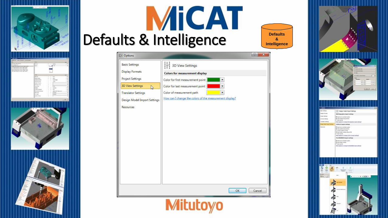
Defaults & Intelligence
Defaults
&
Intelligence

Defaults & IntelligenceDefaults
&
Intelligence

Defaults & IntelligenceDefaults
&
Intelligence

Defaults & IntelligenceDefaults
&
Intelligence
Defaults & IntelligenceDefaults
&
Intelligence

Defaults & IntelligenceDefaults
&
Intelligence

Defaults & IntelligenceDefaults
&
Intelligence

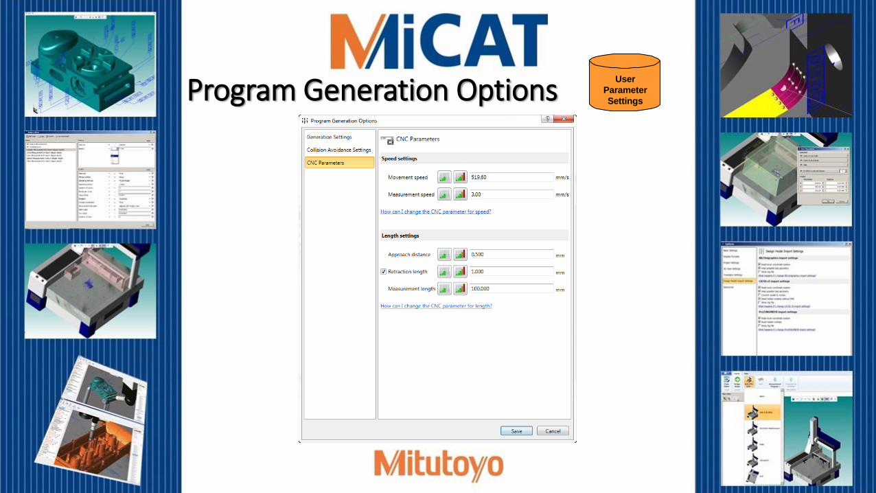
Program Generation Options
User
Parameter
Settings

User
Parameter
SettingsProgram Generation Options

User
Parameter
SettingsProgram Generation Options
User
Parameter
SettingsProgram Generation Options

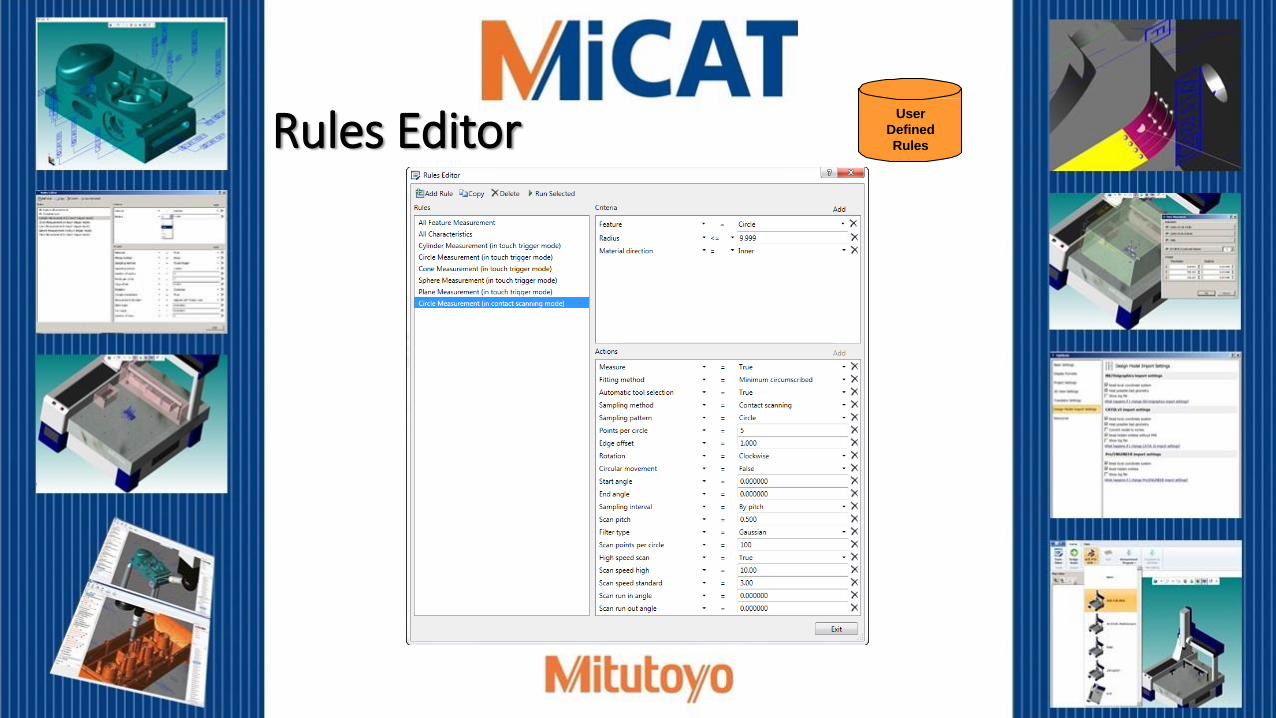
User Defined Rules
User
Defined
Rules
User
Defined
RulesRules Editor

User
Defined
RulesUser Defined Rules
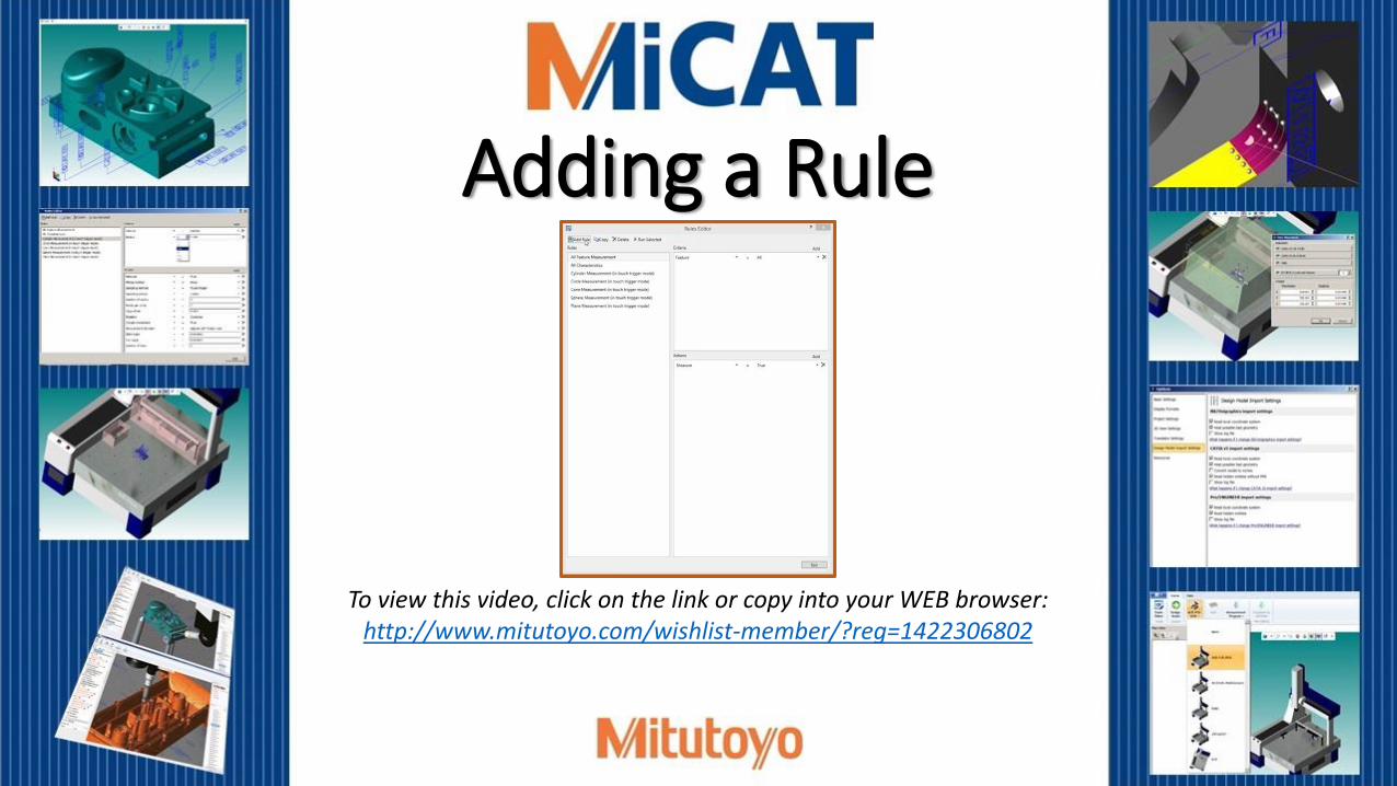
Adding a Rule
To view this video, click on the link or copy into your WEB browser:http://www.mitutoyo.com/wishlist-member/?reg=1422306802
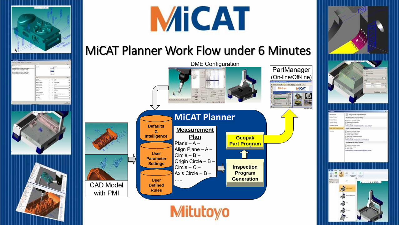
MiCAT Planner Work Flow under 6 Minutes
User
Parameter
Settings
User
Defined
Rules
Defaults
&
Intelligence
CAD Modelwith PMI
DME Configuration
MiCAT PlannerMeasurement
PlanPlane – A –Align Plane – A –Circle – B –Origin Circle – B –Circle – C –Axis Circle – B –…..
Inspection
Program
Generation
Geopak
Part Program
PartManager(On-line/Off-line)

MiCAT Planner Work Flow under 6 Minutes
To view this video, click on the link or copy into your WEB browser:http://www.mitutoyo.com/wishlist-member/?reg=1422306802

Part Program Tasks Automatically Completed
by MiCAT Planner
• Part Setup Information• Operator Warnings (Optional On/Off)• All Positional Moves• All Measurement Commands• All Sensor Changes• All GD&T Applied • Inspection Results Report Generated

• Flexibility – a program can automatically be generated for most part features or for just a selected few, and each program can be saved as part of a complete project
• Customization – generate a project for First Article Inspection or in-process production or final inspection from the same MBD
To view this video, click on the link or copy into your WEB browser:http://www.mitutoyo.com/wishlist-member/?reg=1422306802
Managing Projects

• Associativity – locate and view the relationships of features and characteristics quickly and easily
To view this video, click on the link or copy into your WEB browser:http://www.mitutoyo.com/wishlist-member/?reg=1422306802
Associativity

• GD&T Wizard – Easily add PMI to a ‘geometry only’ CAD model
To view this video, click on the link or copy into your WEB browser:http://www.mitutoyo.com/wishlist-member/?reg=1422306802
Adding GD&T

Models (ex. Prototypes) without PMI?
• Just select the features to be measured…

• Selective animation – preview selected part program paths for verification, review, and measurement coverage
Animating a Selection
To view this video, click on the link or copy into your WEB browser:http://www.mitutoyo.com/wishlist-member/?reg=1422306802

Overall MiCAT Planner Benefits Streamlined processes
Improved productivity
Reduced manufacturing costs
Enhanced traceability
Up to a 95-percent savings in time compared to
drawing-based methods
Suppliers receive a single CAD file to inspect a
part

Overall MiCAT Planner Benefits Features and characteristics are transferred
directly into the inspection software, reducing
the risk of misinterpretation
CMM configurations can be changed at any point
Enhanced workflow automation
Part measurement consistency
Additional Information
http://www.mitutoyo.com/about/contacting-mac/send-literaturecontact-me/
Send Literature/Contact Me
http://www.mitutoyo.com/about/contacting-mac/product-demo-request/
Product Demo Request
Thank you…


