
J-1 Visit www.GemsSensors.com for most current information.
SOLEN
OID
VALVES
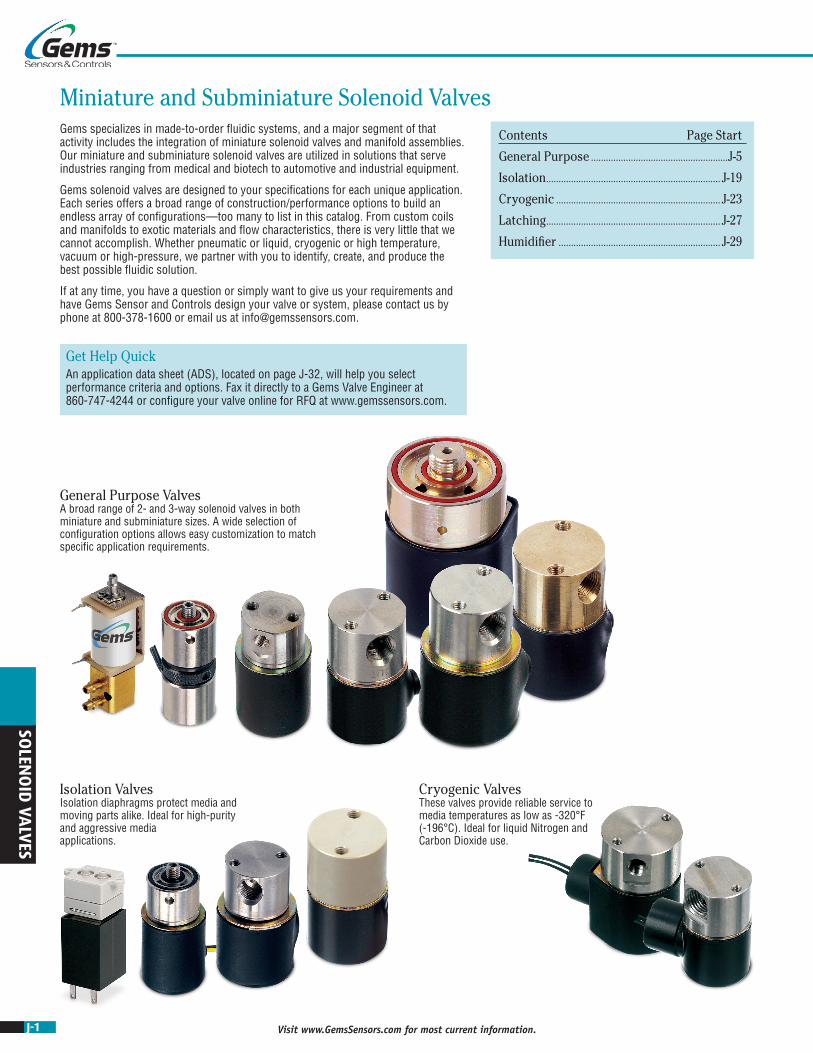
Miniature and Subminiature Solenoid Valves
Get Help QuickAn application data sheet (ADS), located on page J-32, will help you select performance criteria and options. Fax it directly to a Gems Valve Engineer at 860-747-4244 or configure your valve online for RFQ at www.gemssensors.com.
Contents Page Start
General Purpose .......................................................J-5
Isolation ...................................................................... J-19
Cryogenic .................................................................. J-23
Latching ...................................................................... J-27
Humidifier ................................................................. J-29
Gems specializes in made-to-order fluidic systems, and a major segment of that activity includes the integration of miniature solenoid valves and manifold assemblies. Our miniature and subminiature solenoid valves are utilized in solutions that serve industries ranging from medical and biotech to automotive and industrial equipment.
Gems solenoid valves are designed to your specifications for each unique application. Each series offers a broad range of construction/performance options to build an endless array of configurations—too many to list in this catalog. From custom coils and manifolds to exotic materials and flow characteristics, there is very little that we cannot accomplish. Whether pneumatic or liquid, cryogenic or high temperature, vacuum or high-pressure, we partner with you to identify, create, and produce the best possible fluidic solution.
If at any time, you have a question or simply want to give us your requirements and have Gems Sensor and Controls design your valve or system, please contact us by phone at 800-378-1600 or email us at [email protected].
Cryogenic Valves These valves provide reliable service to media temperatures as low as -320°F (-196°C). Ideal for liquid Nitrogen and Carbon Dioxide use.
Isolation Valves Isolation diaphragms protect media and moving parts alike. Ideal for high-purity and aggressive media applications.
General Purpose Valves A broad range of 2- and 3-way solenoid valves in both miniature and subminiature sizes. A wide selection of configuration options allows easy customization to match specific application requirements.
J-2Visit www.GemsSensors.com for most current information.
SOLE
NO
ID V
ALV
ES
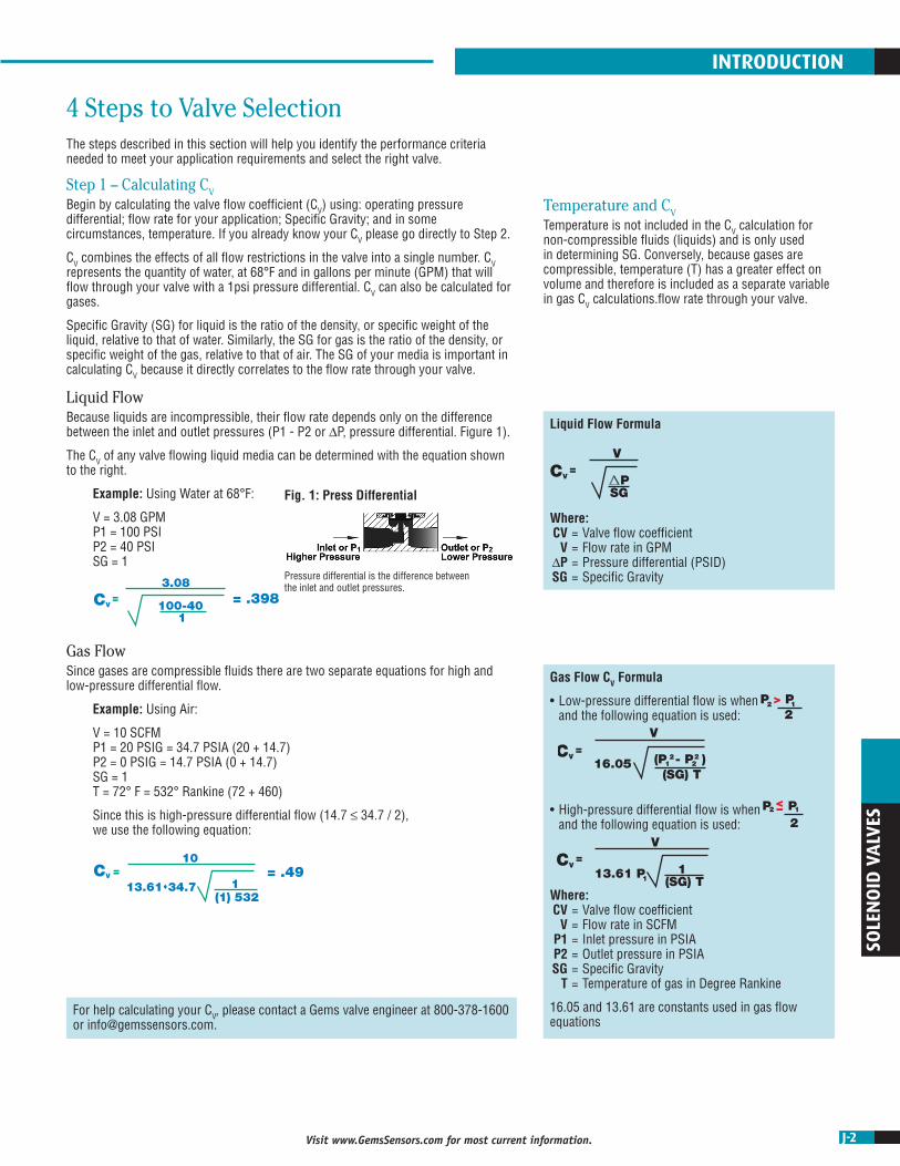
Fig. 1: Press Differential
Pressure differential is the difference betweenthe inlet and outlet pressures.
For help calculating your CV, please contact a Gems valve engineer at 800-378-1600 or [email protected].
P SG
(P - P ) (SG) T
P > P
1(SG) T
CV=
V
CV=
3.08
100-40 1
CV=
V
13.61 P1
2 1
2
CV=
V
16.052
12
2
1(1) 532
CV =10
13.6134.7
P P2 1
2
< –
= .398
= .49
Gas Flow CV Formula
• Low-pressure differential flow is when and the following equation is used:
• High-pressure differential flow is when and the following equation is used:
Where: CV = Valve flow coefficient V = Flow rate in SCFM P1 = Inlet pressure in PSIA P2 = Outlet pressure in PSIA SG = Specific Gravity T = Temperature of gas in Degree Rankine
16.05 and 13.61 are constants used in gas flow equations
P SG
(P - P ) (SG) T
P > P
1(SG) T
CV=
V
CV=
3.08
100-40 1
CV=
V
13.61 P1
2 1
2
CV=
V
16.052
12
2
1(1) 532
CV =10
13.6134.7
P P2 1
2
< –
= .398
= .49
P SG
(P - P ) (SG) T
P > P
1(SG) T
CV=
V
CV=
3.08
100-40 1
CV=
V
13.61 P1
2 1
2
CV=
V
16.052
12
2
1(1) 532
CV =10
13.6134.7
P P2 1
2
< –
= .398
= .49
P SG
(P - P ) (SG) T
P > P
1(SG) T
CV=
V
CV=
3.08
100-40 1
CV=
V
13.61 P1
2 1
2
CV=
V
16.052
12
2
1(1) 532
CV =10
13.6134.7
P P2 1
2
< –
= .398
= .49
P SG
(P - P ) (SG) T
P > P
1(SG) T
CV=
V
CV=
3.08
100-40 1
CV=
V
13.61 P1
2 1
2
CV=
V
16.052
12
2
1(1) 532
CV =10
13.6134.7
P P2 1
2
< –
= .398
= .49
P SG
(P - P ) (SG) T
P > P
1(SG) T
CV=
V
CV=
3.08
100-40 1
CV=
V
13.61 P1
2 1
2
CV=
V
16.052
12
2
1(1) 532
CV =10
13.6134.7
P P2 1
2
< –
= .398
= .49
Liquid Flow Formula
Where: CV = Valve flow coefficient V = Flow rate in GPM ∆P = Pressure differential (PSID) SG = Specific Gravity
P SG
(P - P ) (SG) T
P > P
1(SG) T
CV=
V
CV=
3.08
100-40 1
CV=
V
13.61 P1
2 1
2
CV=
V
16.052
12
2
1(1) 532
CV =10
13.6134.7
P P2 1
2
< –
= .398
= .49
INTRODUCTION
Liquid FlowBecause liquids are incompressible, their flow rate depends only on the difference between the inlet and outlet pressures (P1 - P2 or ∆P, pressure differential. Figure 1).
The CV of any valve flowing liquid media can be determined with the equation shown to the right.
Example: Using Water at 68°F:
V = 3.08 GPM P1 = 100 PSI P2 = 40 PSI SG = 1
Gas FlowSince gases are compressible fluids there are two separate equations for high and low-pressure differential flow.
Example: Using Air:
V = 10 SCFM P1 = 20 PSIG = 34.7 PSIA (20 + 14.7) P2 = 0 PSIG = 14.7 PSIA (0 + 14.7) SG = 1 T = 72° F = 532° Rankine (72 + 460)
Since this is high-pressure differential flow (14.7 ≤ 34.7 / 2), we use the following equation:
The steps described in this section will help you identify the performance criteria needed to meet your application requirements and select the right valve.
Step 1 – Calculating CVBegin by calculating the valve flow coefficient (CV) using: operating pressure differential; flow rate for your application; Specific Gravity; and in some circumstances, temperature. If you already know your CV please go directly to Step 2.
CV combines the effects of all flow restrictions in the valve into a single number. CV represents the quantity of water, at 68°F and in gallons per minute (GPM) that will flow through your valve with a 1psi pressure differential. CV can also be calculated for gases.
Specific Gravity (SG) for liquid is the ratio of the density, or specific weight of the liquid, relative to that of water. Similarly, the SG for gas is the ratio of the density, or specific weight of the gas, relative to that of air. The SG of your media is important in calculating CV because it directly correlates to the flow rate through your valve.
Temperature and CVTemperature is not included in the CV calculation for non-compressible fluids (liquids) and is only used in determining SG. Conversely, because gases are compressible, temperature (T) has a greater effect on volume and therefore is included as a separate variable in gas CV calculations.flow rate through your valve.
4 Steps to Valve Selection

J-3 Visit www.GemsSensors.com for most current information.
SOLEN
OID
VALVES
Gems specializes in the design and manufacturing of custom solenoid valves and fluidic systems. If you don’t see what you’re looking for, or have a question, contact us at 800-378-1600 or [email protected].
Step 2 – Valve FunctionIdentify how your valve will function in your application. Pick from the choices below.
An important note regarding CV and valve function:
The CV calculated will apply to either the Body Orifice or the Stop Orifice depending on the valve’s function.
For example, the Stop Orifice for a 3-way normally closed valve, when de-energized, is the exhaust port. In other words, CV is calculated using the specific Inlet Pressure (P1) and Outlet Pressure (P2) for the flow paths described below.
Flow Key
Blocked Flow
Free Flow

J-4Visit www.GemsSensors.com for most current information.
SOLE
NO
ID V
ALV
ES
General Purpose
Function 2- & 3-Way
Media Gas Only Gas & Liquid
Size Sub-Miniature Miniature
CV Range 0.018 - 0.070 0.019 - 0.430 0.045 - 0.880
Port Configuration
#10-32 Manifold Mount
Barb (1/16, 5/64, 1/8), Manifold or Face-Mount
#10-32, 1/8, 1/4 NPT,
Manifold Mount
1/8, 1/4, 3/8 NPT, Manifold Mount
Orifice Dia (in) 0.032 - 0.078 0.031 - 0.052 0.032 - 0.156 0.062 - 0.210 0.047 - 0.375
Power (watt) 0.65, 2 0.5, 1, 2 6 7 10
MOPD (psi) 175 250 100 1000 400 900
Valve Series E, EH G, GH M A B C D
Pages J-7, J-8 J-9, J-10 J-5, J-6 J-11, J-12 J-13, J-14 J-15, J-16 J-17, J-18
Isolation Cryogenic Latching
Function 2-Way, Normally Closed Only 2-Way, Normally Closed Only 2- & 3-Way
Media Gas & Liquid Liquid Gas & Liquid
Size Miniature Miniature Minature
CV Range 0.020 - 0.300 0.045 - 0.440 0.040 - 0.770 0.018 - 0.43
Port Configuration
#10-32, 1/8 NPT, 1/4 NPT, Manifold Mount
1/8, 1/4 NPT 1/8, 1/4, 3/8 NPT#10-32,
1/8 NPT, 1/4 NPT, Manifold Mount
Orifice Dia (in) 0.032 - 0.156 0.046 - 0.188 0.046 - 0.250 0.032 - 0.156
Power (watt) 4.5, 7 9 15 5 - 9
MOPD (psi) 50 (Plastic Body), 150 900 1000* 100
Valve Series AS BS B-Cryo D-Cryo BL
Pages J-19, J-20 J-21, J-22 J-23, J-24 J-25, J-26 J-27, J-28
*Consult factory for higher MOPD.
If you would like assistance with your selection, want to modify a valve, or simply want a sounding board please contact a Gems™ valve engineer at 800-378-1600 or [email protected].
We specialize in application specific valves. Our modular valve designs, coupled with our cutting edge 3D modeling and innovative CNC manufacturing capabilities, result in fluidic systems that are truly adaptable to any originally manufactured equipment.
INTRODUCTION
Step 3 – Identify Your Valve SeriesSelect possible valve series candidate using the overview charts below. Begin by choosing the category for your application:
• General Purpose • Isolation • Cryogenic
Using the charts, select maximum operating pressure differential (MOPD), the CV, function, and additional specifications needed for your application to select possible valve series. The detailed performance specs for each series are located on the corresponding pages listed on the chart.
Step 4 – Make Your Selection and Configure Your ValveComplete your valve design by selecting the additional design parameters to build the best possible valve. For example:
• Materials needed for your media (stainless steel, brass, fluoroelastomer, EPDM, etc.) • Coil construction (lead wire, quick connect spade, grommet, conduit, yoke, etc.) • Port configuration • Manifold assembly • Voltage
For help selecting the additional options for your valve or if you want to confirm that your selection is the best choice or work with an engineer on integrating a fluidic system into your application, contact us at 800-378-1600 or [email protected]. We are happy to assist. You can also place orders through these same channels.

J-5 Visit www.GemsSensors.com for most current information.
SOLEN
OID
VALVES
0.392
0.196
0.250(4) PLC’S
2.02(3-WAY)
1.78(2-WAY N.C.)
0.305
0.675
ø.125 THRUMOUNTING HOLES
STOP PORT(2-WAY N.O. & 3-WAY)
0.610
0.305
0.245
0.270
0.500
0.3120.125
0.7330.281
0.265(UNDERSEAT)
(OVERSEAT)
VOLTAGEAPPLIED TO
TOP TERMINALS
0.500
0.62
0.863
ø.73
0.15
1.76(3-WAY)
1.51(2-WAY N.C.)
0.20
#10-32 UNF-2AMOUNTING STUD
(UNDERSEAT)
(OVERSEAT)
32 RMSOVER ø.75
(UNDERSEAT)
(OVERSEAT)(ø.089)
#10-32 UNF-2B x0.25 MIN. FULL TH’D
ø.125 SPANNERHOLE, (3) PLC’S EQUALLY SPACED
R.220
O-RINGS
MANIFOLDMATING DIMENSIONS
DimensionsThreaded Port Body Manifold Mount Body
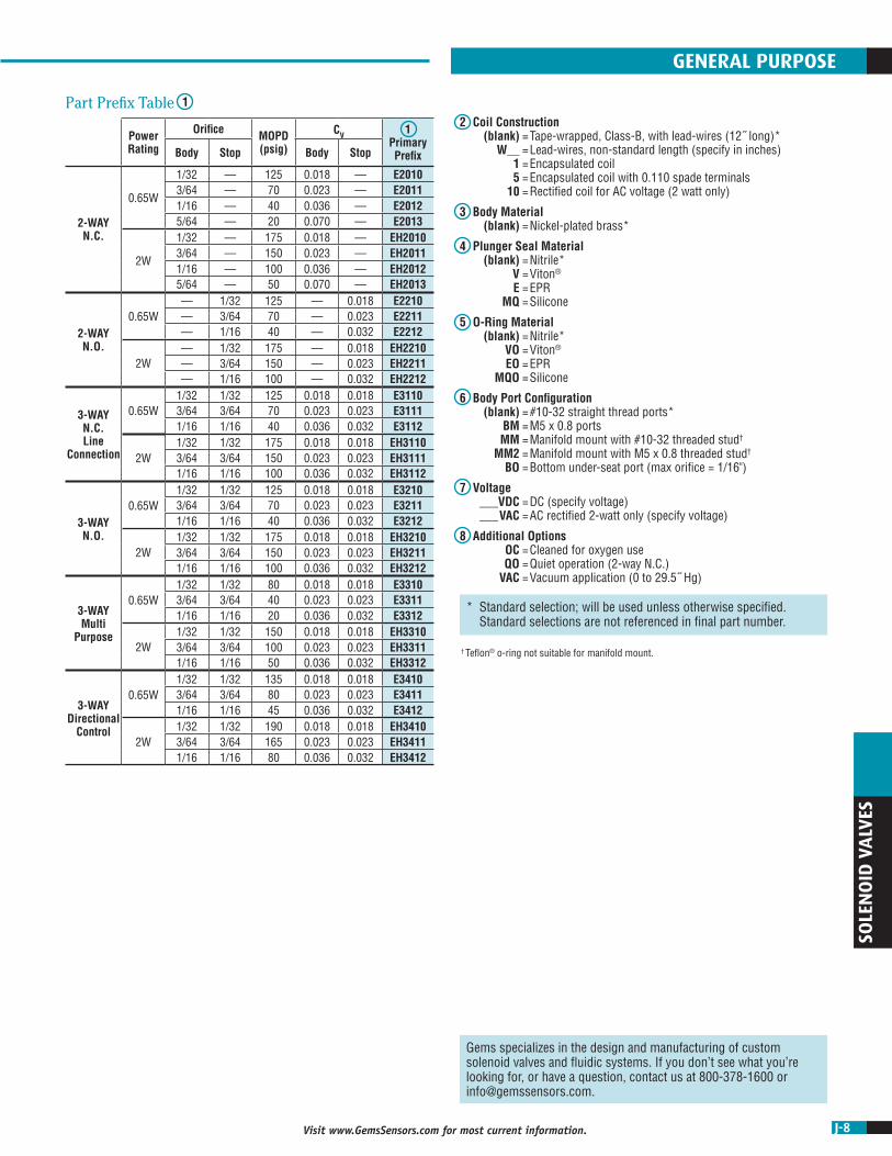
M Series – Subminiature MOPD: 100 PSI CV Range: 0.018 to 0.070 As Low As 0.5 Watts
The M Series implements efficient power conservation in a solenoid valve that is specifically designed for sub-miniature two- and three-way pneumatic and select liquid applications. Field proven to exceed performance requirements in battery-powered applications, the M Series can be designed for extreme low wattage conditions. With a compact size, consistent high-speed response time, and reliable operation over 200 million cycles, the M Series delivers extended performance and precision flow control in a small lightweight environment.
Typical ApplicationsIdeal for inline PC interfacing and manifold assemblies: • Medical and Therapeutic Healthcare • Clinical Chemistry and Analysis Equipment • Drop-on-Demand Printing • Environmental Instrumentation
MB 31 5 - E B 3 3 - P 201 - OC
13
24
56
78
910
Primary Prefix Valve
TypeOrifice Size
Plunger Seal/O-Ring
Material Body Material
Body Port Configuration
Stop Port Configuration
Coil Construction
Voltage
Additional Options
How To OrderUse the Bold characters from the choices listed on the following page to construct a product code.
Note: After the Primary Prefix, any "-Code" may be blank when standard (blank) selections are specified.
Example:
MB315-EB33-P-201
1 Watt 3-Way N.C. solenoid valve with a 0.052˝ orifice, EPDM plunger seal/o-ring, brass body, 1/8˝ barb body and stop port, P.C. board mount (4-pin), operating at 5 VDC, and is cleaned for oxygen use.

J-6Visit www.GemsSensors.com for most current information.
SOLE
NO
ID V
ALV
ES
Power Rating Orifice MOPD
(psig)CV 1 Primary
PrefixBody
0.5 Watt0.031 25 0.020 MA0.052 10 0.038 MA
1 Watt0.031 50 0.020 MB0.052 25 0.038 MB
2 Watts0.031 100 0.020 MC0.052 50 0.038 MC
Gems specializes in the design and manufacturing of custom solenoid valves and fluidic systems. If you don’t see what you’re looking for, or have a question, contact us at 800-378-1600 or [email protected].
Flow Schematic
OUT
IN
DE-ENERGIZED ENERGIZED DE-ENERGIZED ENERGIZED DE-ENERGIZED ENERGIZED DE-ENERGIZED ENERGIZED
DE-ENERGIZED ENERGIZEDDE-ENERGIZED ENERGIZEDDE-ENERGIZED
3-WAY MULTI-PURPOSE
3-WAY NORMALLY CLOSED 3-WAY NORMALLY OPEN2-WAY NORMALLY CLOSED 2-WAY NORMALLY OPEN
3-WAY DIRECTIONAL CONTROL
ENERGIZED
IN
CYL
N.O.
COM
N.C.
COM
N.C.
COM
N.C.
COM
N.C.
IN
N.C.
IN
N.C.
N.O. N.O.
AND
N.O. N.O. N.O.
IN
IN IN
CYL CYL CYL
EXH EXH
EXH EXH
OUT OUT OUT
IN
IN IN
Flow Key
Blocked Flow
Free Flow
GENERAL PURPOSE
2 Valve Type 20 = 2-Way normally closed 22 = 2-Way normally open 30 = 3-Way normally closed (free vent) 31 = 3-Way normally closed (line connection) 32 = 3-Way normally open 33 = 3-Way multi-purpose 34 = 3-Way directional control
3 Orifice Size 2 = 0.031˝ 5 = 0.052˝
4 Plunger Seal / O-Ring Material V = Viton® N = Nitrile E = EPDM
5 Body Material B = Brass A = Aluminum
6 Body Port Configuration1 0 = Face mount 1 = 1/16˝ barb 2 = 5/64˝ or 3/32˝ barb 3 = 1/8˝ barb 4 = Manifold mount, #10-32 UNF-2A stud† 5 = #10-32 UNF-2B female thread (180° apart only) 6 = 1/8˝-27 NPT ports (180° apart only)
7 Stop Port Configuration1 0 = No barb (Standard for 2-way NC & 3-way free vent)2 3 1 = 1/16˝ barb (.031˝ orifice only) 2 = 5/64˝ or 3/32˝ barb 3 = 1/8˝ barb
8 Coil Construction (Tape-Wrapped, 130°C Class B) U = P.C. board solderable (2-pin) P = P.C. board mount (4-pin)4 Q = Quick connect 0.110 spade L = Lead-wires, #26 AWG, 18˝ long W__ = Lead-wires (Specify length in inches)
9 Voltage 200 = 3 VDC 201 = 5 VDC 203 = 12 VDC 204 = 24 VDC ___VDC = DC (specify voltage) ___VAC = AC Rectified 2-watt coil only (specify voltage, lead-wires only)
10 Additional Options OC = Cleaned for oxygen use VAC = Vacuum application (0 to 27˝ Hg)Notes1. Barbs are brass.2. For Stop Port Configuration, must select "0" for valve type 20 (2-way NC) and for type
30 (3-way NC Free Vent).3. For Stop Port Configuration, must select "1" or "2" or "3" for valve types 22 (2-way
NO), 31 (3-way NC Line Connect), 32 (3-way NO), 33 (3-way MP), and 34 (3-way DC). Selection "0" can not be used.
4. 2 pins near stop are active.
† Teflon® o-ring not suitable for manifold mount.
1Part Prefix Table

J-7 Visit www.GemsSensors.com for most current information.
SOLEN
OID
VALVES
ø.73
1.61
0.250
#6-32 UNC-2B x0.22 MIN. FULL TH’D
(2) PLC’S
0.500
0.17
#24 AWG PVC LEADS x 12˝
STOP PORT(2-WAY N.O. & 3-WAY)#10-32 UNF-2B x0.18 MIN. FULL TH’D
0.68FLATS
(OVERSEAT)
(UNDERSEAT)
BODY PORTS#10-32 UNF-2B x
0.18 MIN. FULL TH’D(2) PLC’S
ø.73
DimensionsThreaded Port Body Manifold Mount Body
Example:
E2010-W24-1-V-VO-24VDC-OC
E-Series 2-Way N.C. solenoid valve, with 24˝ lead-wires from an encapsulated coil, nickel-plated brass body, Viton® plunger seal, Viton® o-ring, #10-32 straight thread ports, operating at 24 VDC, and is cleaned for oxygen use.
E & EH Series – Subminiature Gas MOPD: 175 PSI CV Range: 0.018 to 0.070 0.65 Watts or 2 Watts
A 2- or 3-way sub-miniature solenoid valve that delivers faster response times—and higher flow rates, the E & EH Series is specifically engineered for air and dry gas applications. A nickel-plated body and coil housing construction produces a highly durable, corrosion resistant valve. With a wattage range of 0.65–2 the E & EH Series provides versatility for power conserving, high pressure, and high flow applications.
Typical Applications • Medical and Respiratory Healthcare • Printing Machinery and Sorting Equipment • Automated Packaging Equipment • Air Monitoring Systems
E2010 - W24-1 - V - VO - 24VDC - OC
12 5
4 78
3 6Primary Prefix Coil
ConstructionO-Ring
Material
Plunger Seal
Material
Voltage
Additional Options
Body Material*
Body Port Configuration*
How To OrderUse the Bold characters from the choices listed on the following page to construct a product code.
* Blank entry indicates a "Standard" selection (#10-32 straight thread ports, in this case).
0.165 ±0.025
1.53
O-RINGS (OVERSEAT)
#10-32 UNF-2AMOUNTING STUD
0.15
Ø.125 SPANNER HOLE(3) PLC'S EQUALLY SPACED
Ø.73
(UNDERSEAT)
(OVERSEAT)(Ø.089)
R.220
32 RMSOVER Ø.75
(UNDERSEAT)
#10-32 UNF-2B x0.25 MIN. FULL TH'D
MANIFOLDMATING DIMENSIONS
J-8Visit www.GemsSensors.com for most current information.
SOLE
NO
ID V
ALV
ES
Power Rating
Orifice MOPD(psig)
CV 1 Primary PrefixBody Stop Body Stop
2-WAY N.C.
0.65W
1/32 — 125 0.018 — E20103/64 — 70 0.023 — E20111/16 — 40 0.036 — E20125/64 — 20 0.070 — E2013
2W
1/32 — 175 0.018 — EH20103/64 — 150 0.023 — EH20111/16 — 100 0.036 — EH20125/64 — 50 0.070 — EH2013
2-WAY N.O.
0.65W— 1/32 125 — 0.018 E2210— 3/64 70 — 0.023 E2211— 1/16 40 — 0.032 E2212
2W— 1/32 175 — 0.018 EH2210— 3/64 150 — 0.023 EH2211— 1/16 100 — 0.032 EH2212
3-WAY N.C. Line
Connection
0.65W1/32 1/32 125 0.018 0.018 E31103/64 3/64 70 0.023 0.023 E31111/16 1/16 40 0.036 0.032 E3112
2W1/32 1/32 175 0.018 0.018 EH31103/64 3/64 150 0.023 0.023 EH31111/16 1/16 100 0.036 0.032 EH3112
3-WAY N.O.
0.65W1/32 1/32 125 0.018 0.018 E32103/64 3/64 70 0.023 0.023 E32111/16 1/16 40 0.036 0.032 E3212
2W1/32 1/32 175 0.018 0.018 EH32103/64 3/64 150 0.023 0.023 EH32111/16 1/16 100 0.036 0.032 EH3212
3-WAY Multi
Purpose
0.65W1/32 1/32 80 0.018 0.018 E33103/64 3/64 40 0.023 0.023 E33111/16 1/16 20 0.036 0.032 E3312
2W1/32 1/32 150 0.018 0.018 EH33103/64 3/64 100 0.023 0.023 EH33111/16 1/16 50 0.036 0.032 EH3312
3-WAY Directional
Control
0.65W1/32 1/32 135 0.018 0.018 E34103/64 3/64 80 0.023 0.023 E34111/16 1/16 45 0.036 0.032 E3412
2W1/32 1/32 190 0.018 0.018 EH34103/64 3/64 165 0.023 0.023 EH34111/16 1/16 80 0.036 0.032 EH3412
* Standard selection; will be used unless otherwise specified. Standard selections are not referenced in final part number.
Gems specializes in the design and manufacturing of custom solenoid valves and fluidic systems. If you don’t see what you’re looking for, or have a question, contact us at 800-378-1600 or [email protected].
GENERAL PURPOSE
2 Coil Construction (blank) = Tape-wrapped, Class-B, with lead-wires (12˝ long)* W__ = Lead-wires, non-standard length (specify in inches) 1 = Encapsulated coil 5 = Encapsulated coil with 0.110 spade terminals 10 = Rectified coil for AC voltage (2 watt only)
3 Body Material (blank) = Nickel-plated brass*
4 Plunger Seal Material (blank) = Nitrile* V = Viton® E = EPR MQ = Silicone
5 O-Ring Material (blank) = Nitrile* VO = Viton® EO = EPR MQO = Silicone
6 Body Port Configuration (blank) = #10-32 straight thread ports* BM = M5 x 0.8 ports MM = Manifold mount with #10-32 threaded stud† MM2 = Manifold mount with M5 x 0.8 threaded stud† BO = Bottom under-seat port (max orifice = 1/16")
7 Voltage ___VDC = DC (specify voltage) ___VAC = AC rectified 2-watt only (specify voltage)
8 Additional Options OC = Cleaned for oxygen use QO = Quiet operation (2-way N.C.) VAC = Vacuum application (0 to 29.5˝ Hg)
1Part Prefix Table
† Teflon® o-ring not suitable for manifold mount.

J-9 Visit www.GemsSensors.com for most current information.
SOLEN
OID
VALVES
DimensionsThreaded Port Body Manifold Mount Body
ø.88
ø.73
1.76
0.56
0.250
0.500
0.17
#26 AWG PVC LEADS x 12˝
STOP PORT(2-WAY N.O. & 3-WAY)#10-32 UNF-2B x0.18 MIN. FULL TH’D
(OVERSEAT)
(UNDERSEAT)
0.68FLATS
BODY PORTS#10-32 UNF-2B x
0.18 MIN. FULL TH’D(2) PLC’S
#6-32 UNC-2B x0.22 MIN. FULL TH’D
(2) PLC’S O-RINGS (OVERSEAT)
#10-32 UNF-2AMOUNTING STUD
Ø.73
(UNDERSEAT)
(OVERSEAT)(Ø.089)
R.220
32 RMSOVER Ø.75
(UNDERSEAT)
#10-32 UNF-2B x0.25 MIN. FULL TH'D
MANIFOLDMATING DIMENSIONS
0.165 ±0.025
1.76
0.15
Ø.125 SPANNERHOLE, (3) PLC'SEQUALLY SPACED
G & GH Series – Subminiature MOPD: 250 PSI CV Range: 0.018 to 0.070 0.65 Watts or 2 Watts
This extremely versatile 2- or 3-way sub-miniature valve gives you the option of choosing the highly durable stainless steel or the lightweight corrosion resistant acetal body, to meet your overall design parameters. Select stainless steel or Delrin®, and other meterials available to resist corrosion in most acids and alkaline solutions, or pick acetal for a tough and heat resistant metal substitute to meet your weight and chemical inert requirements.
Typical ApplicationsStainless Steel Bodies: • Hospital Equipment • Laboratory Equipment • Air Sampling Systems
Acetal Bodies: • Water Purification Systems • Analytical Equipment
Example:
G2214-5-E-EO-5VDC
G-Series 303 Stainless Steel 2-Way N.O. solenoid valve, with tape-wrapped, Class-B, with lead-wires (12˝ long), encapsulated coil with 0.110 spade terminals, EPR plunger seal, EPR o-ring, #10-32 straight thread ports, operating at 5 VDC.
G2214 - 5 - E - EO - 5VDC
12
634
57
Primary Prefix Coil
ConstructionVoltagePlunger Seal
Material
O-Ring Material
Body Port Configuration*
Additional Options*
How To OrderUse the Bold characters from the choices listed on the following page to construct a product code.
* Blank entry indicates a "Standard" selection (#10-32 straight thread ports, in this case).

J-10Visit www.GemsSensors.com for most current information.
SOLE
NO
ID V
ALV
ES
Power Rating
OrificeMOPD(psig)
CV1 Primary Prefix
Body Stop Body Stop 303 Stainless Steel1
2-WAY N.C.
0.65W
0.030 — 125 0.018 — G20120.040 — 70 0.023 — G20130.055 — 40 0.038 — G20140.078 — 20 0.063 — G2015
2W
0.030 — 250 0.018 — GH20120.040 — 175 0.023 — GH20130.055 — 100 0.038 — GH20140.078 — 50 0.063 — GH2015
2-WAY N.O.
0.65W
— 0.030 125 — 0.018 G2212— 0.040 70 — 0.023 G2213— 0.055 40 — 0.038 G2214— 0.078 20 — 0.057 G2215
2W
— 0.030 200 — 0.018 GH2212— 0.040 150 — 0.023 GH2213— 0.055 100 — 0.038 GH2214— 0.078 50 — 0.057 GH2215
3-WAY N.C.
0.65W
0.030 0.030 125 0.018 0.018 G31120.040 0.040 70 0.023 0.023 G31130.055 0.055 40 0.038 0.038 G31140.078 0.078 20 0.063 0.057 G3115
2W
0.032 0.030 200 0.018 0.018 GH31120.040 0.040 150 0.023 0.023 GH31130.055 0.055 100 0.038 0.038 GH31140.078 0.078 50 0.063 0.057 GH3115
3-WAY N.O.
0.65W
0.030 0.030 125 0.018 0.018 G32120.040 0.040 70 0.023 0.023 G32130.055 0.055 40 0.038 0.038 G32140.078 0.078 20 0.057 0.057 G3215
2W
0.030 0.030 175 0.018 0.018 GH32120.040 0.040 150 0.023 0.023 GH32130.055 0.055 80 0.038 0.038 GH32140.078 0.078 40 0.057 0.057 GH3215
3-WAY Multi
Purpose
0.65W
0.030 0.030 80 0.018 0.018 G33120.040 0.040 40 0.023 0.023 G33130.055 0.055 20 0.036 0.029 G33140.078 0.078 10 0.063 0.053 G3315
2W
0.030 0.030 110 0.018 0.018 GH33120.040 0.040 85 0.023 0.023 GH33130.055 0.055 50 0.036 0.029 GH33140.078 0.078 25 0.063 0.057 GH3315
3-WAY Directional
Control
0.65W
0.030 0.030 135 0.018 0.018 G34120.040 0.040 80 0.023 0.023 G34130.055 0.055 45 0.029 0.029 G34140.078 0.078 20 0.063 0.055 G3415
2W
0.030 0.030 190 0.018 0.018 GH34120.040 0.040 165 0.023 0.020 GH34130.055 0.055 80 0.038 0.038 GH34140.078 0.078 40 0.063 0.063 GH3415
* Standard selection; will be used unless otherwise specified. Standard selections are not referenced in final part number.
Notes1. Use prefixes from this column if you plan to select a Body Port Configuration
other than the #10-32 straight thread ports.
† Teflon® o-ring not suitable for manifold mount.
Gems specializes in the design and manufacturing of custom solenoid valves and fluidic systems. If you don’t see what you’re looking for, or have a question, contact us at 800-378-1600 or [email protected].
GENERAL PURPOSE
2 Coil Construction (blank) = Tape-wrapped, Class-B, with lead-wires (12˝ long)* W__ = Lead-wires, non-standard length (specify in inches) 1 = Encapsulated coil 5 = Encapsulated coil with 0.110 spade terminals 10 = Rectified coil for AC voltage (2-watt only)
3 Plunger Seal Material (blank) = Viton®* NB = Nitrile E = EPR N = Neoprene
4 O-Ring Material (blank) = Viton®* NBO = Nitrile EO = EPR NO = Neoprene
5 Body Port Configuration (blank) = #10-32 straight thread ports* LC = 1/8˝-27 NPT ports (2-way valves only) BM = M5 x 0.8 ports MM = Manifold mount with #10-32 threaded stud† MM2 = Manifold mount with M5 x 0.8 threaded stud†
6 Voltage ___VDC = DC (specify voltage) ___VAC = AC Rectified 2-watt only (specify voltage)
7 Additional Options OC = Cleaned for oxygen use TP = PTFE coated plunger VAC = Vacuum application (0 to 29.5˝ Hg)
1Part Prefix Table
J-11 Visit www.GemsSensors.com for most current information.
SOLEN
OID
VALVES
ø1.03
1.97(2-WAY N.C.)
2.28(3-WAY)
0.27
32.5°
#8-32 UNC-2B x0.25 MIN. FULL TH’DON A ø.735 B.C.(2) PLC’S
BODY PORTS1/8-27 NPT(2) PLC’S
#20 AWG BLACKLEADS x 18˝
STOP PORTSAE 45° MALE FLAREWITH 5/16-24 TH’DFOR 1/8˝ O.D. TUBE
(OVERSEAT)
(UNDERSEAT)ø.99
1/8-27 FNPT
2.72TOTALVALVE
HEIGHT
0.28
1/4-28 UNF-2AMOUNTING STUD
Ø.99
(OVERSEAT)
Ø.125 SPANNER HOLES, (4) HOLESEQUALLY SPACED
0.17
1.69 1/4-28 UNF-2Bx 0.33 MIN. FULL TH'D
32
(UNDERSEAT)
32
Ø.359 ±.002
Ø.256 MAX.x 90° C'SINK
R.256
0.035 ±0.002
MANIFOLDMATING DIMENSIONS
(OVERSEAT)1 x Ø.104, ORIFICE ≤ 5/64˝2 x Ø.104, ORIFICE ≥ 3/32˝(UNDERSEAT)
O-RINGS
2.065(2-WAY N.C.)
1/4" SPADE TERMINAL(2) PLC'S
1.100
1.355
0.310
0.595
1.050
1.735
0.032
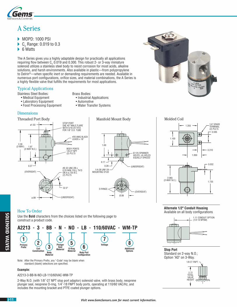
A Series MOPD: 1000 PSI CV Range: 0.019 to 0.3 6 Watts
The A Series gives you a highly adaptable design for practically all applications requiring flow between CV 0.019 and 0.300. This robust 2- or 3-way miniature solenoid utilizes a stainless steel body to resist corrosion for most acids, alkaline solutions, and harsh environments. Also available in plastic—from polypropylene to Delrin®—when specific inert or demanding requirements are needed. Available in numerous port configurations, orifice sizes, and material combinations, the A Series is a highly flexible valve that fulfills the requirements for most applications.
Typical ApplicationsStainless Steel Bodies: • Medical Equipment • Laboratory Equipment • Food Processing Equipment
Brass Bodies: • Industrial Applications • Automotive • Water Transfer Systems
DimensionsThreaded Port Body Molded CoilManifold Mount Body
A2213 - 3 - BB - N - NO - LB - 110/60VAC - WM-TP
13
24
56
78
How To OrderUse the Bold characters from the choices listed on the following page to construct a product code.
Primary Prefix Coil
ConstructionBody
Material
Plunger Seal
Material O-Ring Material
Body Port Configuration
Voltage
Additional Options
Note: After the Primary Prefix, any "-Code" may be blank when standard (blank) selections are specified.
Example:
A2213-3-BB-N-NO-LB-110/60VAC-WM-TP
2-Way N.O. (with 1/8˝-27 NPT stop port adaptor) solenoid valve, with brass body, neoprene plunger seal, neoprene O-ring, 1/4˝-18 FNPT body ports, operating at 110/60 VAC/Hz, and includes the mounting bracket and PTFE coated plunger options.
ø1.03
1.97(2-WAY N.C.)
2.28(3-WAY)
0.27
32.5°
#8-32 UNC-2B x0.25 MIN. FULL TH’DON A ø.735 B.C.(2) PLC’S
BODY PORTS1/8-27 NPT(2) PLC’S
#20 AWG BLACKLEADS x 18˝
STOP PORTSAE 45° MALE FLAREWITH 5/16-24 TH’DFOR 1/8˝ O.D. TUBE
(OVERSEAT)
(UNDERSEAT)ø.99
1/8-27 FNPT
2.72TOTALVALVE
HEIGHT
1.11 CONDUIT OPTION(1/2-14 NPSM)
Stop Port Standard on 2-way N.O.; Option "AD" on 3-Way.
Alternate 1/2" Conduit Housing Available on all body configurations

J-12Visit www.GemsSensors.com for most current information.
SOLE
NO
ID V
ALV
ES
Orifice MOPD(psig)
CV 1 Primary Prefix
Body Stop Body Stop Grommet Housing
Conduit Housing
2-WAY N.C.
1/32 — 1000 0.020 — A2011 A20213/64 — 500 0.035 — A2012 A20221/16 — 300 0.065 — A2013 A20235/64 — 200 0.090 — A2014 A20243/32 — 175 0.155 — A2015 A20251/8 — 100 0.240 — A2016 A20265/32 — 50 0.300 — A2017 A2027
2-WAY N.O. (option AD standard)
— 1/32 200 — 0.019 A2211 A2221— 3/64 150 — 0.040 A2212 A2222— 1/16 100 — 0.075 A2213 A2223
3-WAY N.C.
Free Vent
1/32 1/32 200 0.019 0.019 A3011 A30213/64 3/64 150 0.040 0.040 A3012 A30221/16 3/64 100 0.070 0.040 A3013 A30231/16 1/16 75 0.070 0.070 A3014 A30243/32 3/64 50 0.170 0.040 A3015 A3025
3-WAY N.C. Line
Connection
1/32 1/32 200 0.019 0.019 A3111 A31213/64 3/64 150 0.040 0.040 A3112 A31221/16 3/64 100 0.070 0.040 A3113 A31231/16 1/16 75 0.070 0.070 A3114 A31243/32 3/64 50 0.170 0.040 A3115 A3125
3-WAY N.O.
1/32 1/32 150 0.019 0.019 A3211 A32213/64 3/64 100 0.040 0.040 A3212 A32221/16 3/64 90 0.070 0.040 A3213 A32231/16 1/16 75 0.070 0.070 A3214 A32243/32 3/64 50 0.170 0.040 A3215 A3225
3-WAY Multi
Purpose
1/32 1/32 125 0.019 0.019 A3311 A33213/64 3/64 100 0.040 0.040 A3312 A33221/16 3/64 90 0.070 0.040 A3313 A33231/16 1/16 75 0.070 0.070 A3314 A33243/32 3/64 25 0.170 0.040 A3315 A3325
3-WAY Directional
Control
1/32 1/32 225 0.019 0.019 A3411 A34213/64 3/64 150 0.040 0.040 A3412 A34221/16 3/64 100 0.070 0.040 A3413 A34231/16 1/16 75 0.070 0.070 A3414 A34243/32 3/64 50 0.155 0.040 A3415 A3425
Gems specializes in the design and manufacturing of custom solenoid valves and fluidic systems. If you don’t see what you’re looking for, or have a question, contact us at 800-378-1600 or [email protected].
GENERAL PURPOSE
2 Coil Construction (blank) = Tape-wrapped, Class-B, with 18” lead wires* W___ = Tape-wrapped coil, lead-wires, non-standard length (specify length) 1M = Over molded coil, Class-B, lead-wires 2M = Over molded coil, Class-F, lead-wires 3M = Over molded coil, Class-H, lead-wires 4M = Over molded coil, Class-B, 1/4” spade terminals 5M = Over molded coil, Class F, 1/4” spade terminals 6M = Over molded coil Class H, 1/4” spade terminals 4 = Encapsulated coil, Class-B, 3/16” spade terminals 5 = Encapsulated coil, Class-B, 0.110” spade terminals 8 = Encapsulated coil, Class F, 3/16” spade terminals 10 = Externally rectified coil (lead wires only) 11 = Tape-wrapped coil, Class H, lead wires HC = molded coil, Class F, EN175301-803 Form B DIN, Industrial. 11mm, 2+1 poles HC2 = Encapsulated coil, Class B, EN175301-803 Form C DIN, Industrial, 9.4mm, 2+1 poles
3 Body Material (blank) = 303 Stainless Steel* BB = Brass SB = 304 Stainless Steel SB5 = 316 Stainless Steel SBF = 430F Stainless Steel
1Part Prefix Table
* Standard selection; will be used unless otherwise specified. Standard selections are not referenced in final part number.
4 Plunger Seal Material (blank) = Nitrile* E = EPR GV = Gasoline Viton® (2-way valves only) N = Neoprene NS = Nitrile (NSF/FDA, 2-way valves only) PF = Perfluoroelastomer R = Rulon® (2-way valves only) T = PTFE V = Viton®
5 O-Ring Material (blank) = Nitrile* EO = EPR NO = Neoprene NSO = Nitrile (NSF/FDA, 2-way valves only) PFO = Perfluoroelastomer TO = PTFE VO = Viton®
6 Body Port Configuration (blank) = 1/8-27 NPT female thread* LB = 1/4-18 NPT female thread BD = #10-32 female straight thread (max. orifice = 1/8˝) LT = 1/8-28 BSPT female thread (2-way valves only) LU = 1/4-19 BSPT female thread (2-way valves only) MM = Manifold mount (1/4-28 UNF-2A mounting stud)††† MM3 = Manifold mount (5/16-24 UNF-2A mounting stud)††† OB = Omit body (operator style) MB = Bottom metering (max. orifice = 3/32˝) BI = Bottom over-seat port, female thread (max. orifice = 1/8˝) BIM = Bottom over-seat port, 1/8-27 NPT male thread (max orifice = 5/64˝) brass body only BO = Bottom under-seat port, female thread BOM = Bottom under-seat port, 1/8-27 NPT male thread (max orifice = 1/8˝) brass body only RL = 90° porting - left hand RR = 90° porting - right hand BS = Stop port, #10-32 female straight thread†
7 Voltage†† (see note below) ___VDC = DC (specify DC voltage) ___VAC = AC (specify AC voltage; includes copper shading ring)
8 Additional Options Y = Yoke WM = Mounting bracket TP = PTFE coated plunger AD = 1/8 - 27 NPT stop port adapter (3-way valves only) QO = Quiet operation (2-way valves only) S = Silver shading ring OC = Cleaned for oxygen use VAC = Vacuum application (0 to 29.5˝ Hg) G1 = One-piece 303 Stainless Steel guide assembly G5 = One piece 316 Stainless Steel guide assembly
† Plastic body available, contact Gems. †† Can be AC rectified without shading ring. Use coil construction Code 10. ††† Teflon® o-ring not suitable for manifold mount.
J-13 Visit www.GemsSensors.com for most current information.
ø1.22STOP PORT1/8-27 NPT
#18 AWG BLACKLEADS x 18˝
BODY PORTS1/8-27 NPT(2) PLC’S
(OVERSEAT)
#8-32 UNC-2B x0.25 MIN. FULL TH’D
ON A ø.735 B.C.(2) PLC’S
(UNDERSEAT)
32.5°
0.800.27
2.72(3-WAY)
2.27(2-WAY N.C.)
ø.99
1.26 CONDUIT OPTION(1/2-14 NPSM)
2.265(2-WAY N.C.)
1/4" SPADE TERMINAL(2) PLC'S
1.230
1.460
0.310
0.595
1.090
1.903
0.032
DimensionsThreaded Port Body Molded CoilManifold Mount Body
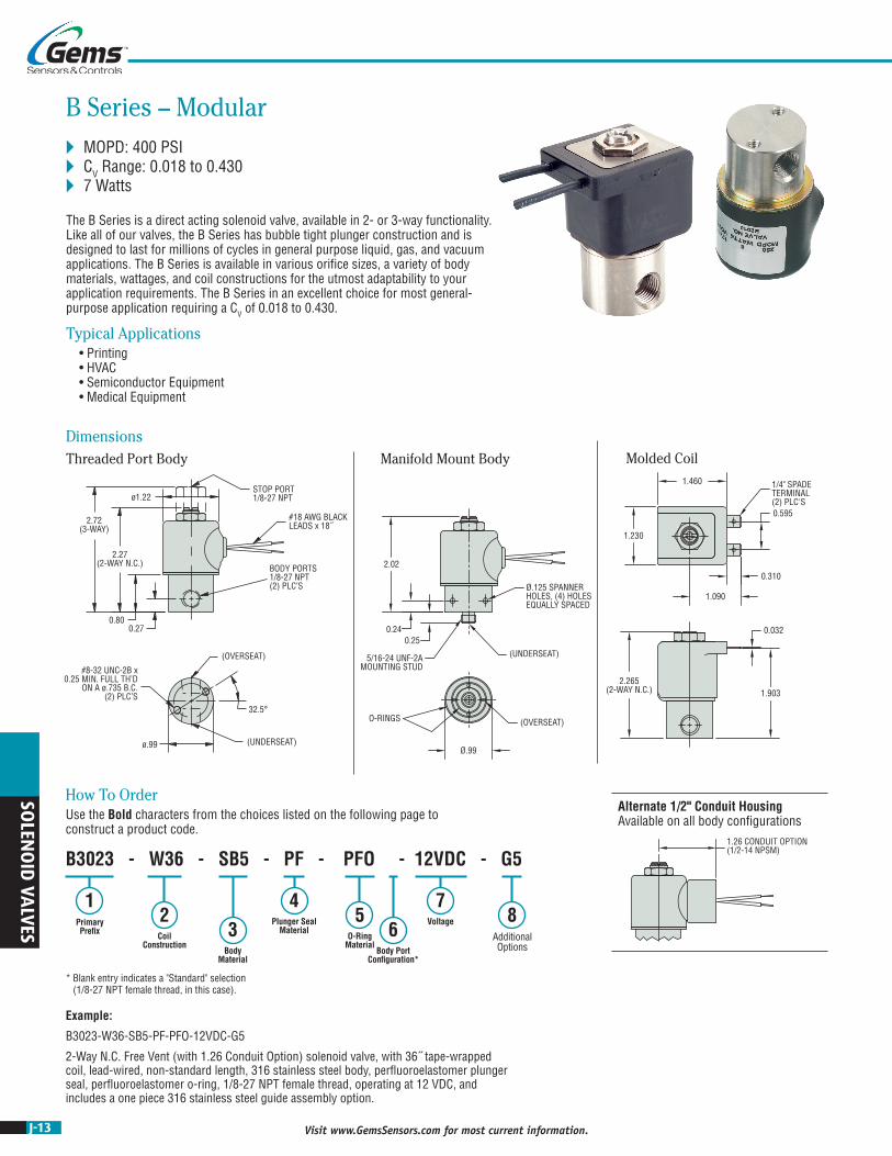
B Series – Modular MOPD: 400 PSI CV Range: 0.018 to 0.430 7 Watts
The B Series is a direct acting solenoid valve, available in 2- or 3-way functionality. Like all of our valves, the B Series has bubble tight plunger construction and is designed to last for millions of cycles in general purpose liquid, gas, and vacuum applications. The B Series is available in various orifice sizes, a variety of body materials, wattages, and coil constructions for the utmost adaptability to your application requirements. The B Series in an excellent choice for most general-purpose application requiring a CV of 0.018 to 0.430.
Typical Applications • Printing • HVAC • Semiconductor Equipment • Medical Equipment
0.25
5/16-24 UNF-2AMOUNTING STUD
Ø.99
O-RINGS
Ø.125 SPANNER HOLES, (4) HOLES EQUALLY SPACED
0.24
2.02
(OVERSEAT)
5/16-24 UNF-2Bx 0.28 MIN. FULL TH'D
(UNDERSEAT)
32
Ø.319 ±.007 MAX.x 90° C'SINK
R.310
(OVERSEAT)2 x Ø.094, ORIFICE ≤ 1/8˝3 x Ø.094, ORIFICE ≥ 5/32˝
MANIFOLDMATING DIMENSIONS
(UNDERSEAT)
Alternate 1/2" Conduit Housing Available on all body configurations
Example:
B3023-W36-SB5-PF-PFO-12VDC-G5
2-Way N.C. Free Vent (with 1.26 Conduit Option) solenoid valve, with 36˝ tape-wrapped coil, lead-wired, non-standard length, 316 stainless steel body, perfluoroelastomer plunger seal, perfluoroelastomer o-ring, 1/8-27 NPT female thread, operating at 12 VDC, and includes a one piece 316 stainless steel guide assembly option.
B3023 - W36 - SB5 - PF - PFO - 12VDC - G5
12
45
78
3 6Primary Prefix Coil
Construction
Plunger Seal Material
O-Ring Material
Voltage
Additional OptionsBody
MaterialBody Port
Configuration*
How To OrderUse the Bold characters from the choices listed on the following page to construct a product code.
* Blank entry indicates a "Standard" selection (1/8-27 NPT female thread, in this case).
SOLEN
OID
VALVES

J-14Visit www.GemsSensors.com for most current information.
Orifice MOPD(psig)
CV1 Primary Prefix
Body Stop Body Stop Grommet Housing
Conduit Housing
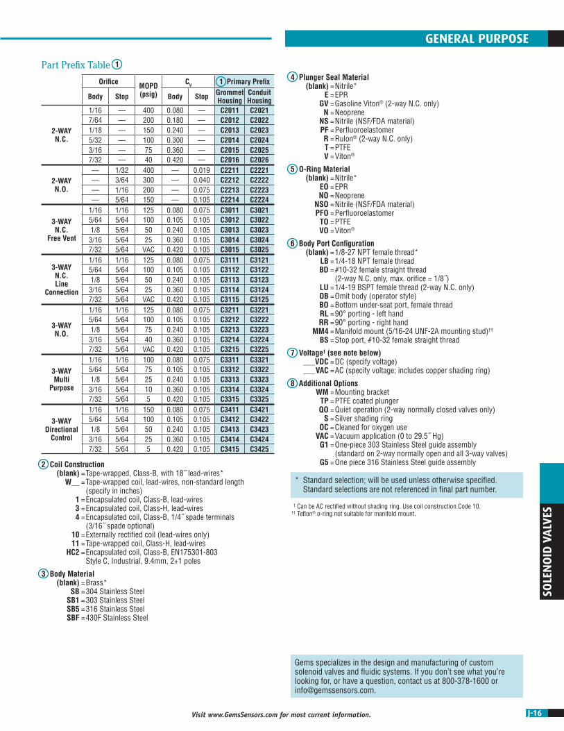
2-WAY N.C.
1/16 — 400 0.065 — B2011 B20215/64 — 300 0.090 — B2012 B20223/32 — 250 0.155 — B2013 B20237/64 — 200 0.200 — B2014 B20241/8 — 150 0.240 — B2015 B20255/32 — 100 0.300 — B2016 B20263/16 — 50 0.430 — B2017 B2027
2-WAY N.O.
— 1/32 400 — 0.019 B2211 B2221— 3/64 300 — 0.040 B2212 B2222— 1/16 200 — 0.075 B2213 B2223— 5/64 150 — 0.090 B2214 B2224
3-WAY N.C.
Free Vent
1/32 1/32 250 0.018 0.018 B3011 B30213/64 3/64 175 0.040 0.040 B3012 B30221/16 1/16 125 0.065 0.070 B3013 B30235/64 5/64 100 0.090 0.090 B3014 B30243/32 5/64 75 0.155 0.090 B3015 B30251/8 5/64 50 0.240 0.090 B3016 B30265/32 5/64 15 0.300 0.090 B3017 B3027
3-WAY N.C. Line
Connection
1/32 1/32 250 0.018 0.018 B3111 B31213/64 3/64 175 0.040 0.040 B3112 B31221/16 1/16 125 0.065 0.070 B3113 B31235/64 5/64 100 0.090 0.090 B3114 B31243/32 5/64 75 0.155 0.090 B3115 B31251/8 5/64 50 0.240 0.090 B3116 B31265/32 5/64 15 0.300 0.090 B3117 B3127
3-WAY N.O.
1/32 1/32 200 0.018 0.018 B3211 B32213/64 3/64 150 0.040 0.040 B3212 B32221/16 1/16 125 0.065 0.070 B3213 B32235/64 5/64 100 0.090 0.090 B3214 B32243/32 5/64 75 0.155 0.090 B3215 B32251/8 5/64 50 0.240 0.090 B3216 B32265/32 5/64 15 0.300 0.090 B3217 B3227
3-WAY Multi
Purpose
1/32 1/32 175 0.018 0.018 B3311 B33213/64 3/64 125 0.040 0.040 B3312 B33221/16 1/16 100 0.065 0.070 B3313 B33235/64 5/64 75 0.090 0.090 B3314 B33243/32 5/64 50 0.155 0.090 B3315 B33251/8 5/64 25 0.240 0.090 B3316 B33265/32 5/64 15 0.300 0.090 B3317 B3327
3-WAY Directional
Control
1/32 1/32 275 0.018 0.018 B3411 B34213/64 3/64 200 0.040 0.040 B3412 B34221/16 1/16 150 0.065 0.070 B3413 B34235/64 5/64 100 0.090 0.090 B3414 B34243/32 5/64 75 0.155 0.090 B3415 B34251/8 5/64 50 0.240 0.090 B3416 B34265/32 5/64 25 0.300 0.090 B3417 B3427
* Standard selection; will be used unless otherwise specified. Standard selections are not referenced in final part number.
GENERAL PURPOSE
1Part Prefix Table
2 Coil Construction (blank) = Tape-wrapped, Class-B, with 18” lead wires* W___ = Tape-wrapped coil, lead-wires, non-standard length (specify length) 1 = Encapsulated coil, Class B, Lead Wires 3 = Encapsulated coil, Class H, Lead Wires 4 = Encapsulated coil, Class-B, 3/16” spade terminals 5 = Encapsulated coil, Class-B, 0.110” spade terminals 8 = Encapsulated coil, Class F, 3/16” spade terminals 10 = Externally rectified coil (lead wires only) 11 = Tape-wrapped coil, Class H, lead wires
2 Coil Construction, continued HC = molded coil, Class F, EN175301-803 Form B DIN, Industrial. 11mm, 2+1 poles HC2 = Encapsulated coil, Class B, EN175301-803 Form C DIN, Industrial, 9.4mm, 2+1 poles TK = Higher efficiency coil (2-way N.C. only)
3 Body Material (blank) = 303 Stainless Steel* BB = Brass SB = 304 Stainless Steel SB5 = 316 Stainless Steel SBF = 430F Stainless Steel
4 Plunger Seal Material (blank) = Nitrile* E = EPR GV = Gasoline Viton® (2-way N.C. only) N = Neoprene NS = Nitrile (NSF/FDA material) PF = Perfluoroelastomer R = Rulon® (2-way N.C. only) T = PTFE V = Viton®
6 Body Port Configuration (blank) = 1/8-27 NPT female thread* LB = 1/4-18 NPT female thread BD = #10-32 female straight thread (max. orifice = 1/8˝) LT = 1/8-28 BSPT female thread LU = 1/4-19 BSPT female thread (2-way N.C. only) MM = Manifold mount (1/4-28 UNF-2A mounting stud)††† MM3 = Manifold mount (5/16-24 UNF-2A mounting stud)††† OB = Omit body (operator style) MB = Bottom metering (2-way N.C. only) BI = Bottom over-seat port, female thread (max. orifice = 1/8˝) BIM = Bottom over-seat port, 1/8-27 NPT male thread (max. orifice = 5/64˝, brass body only) BO = Bottom under-seat port, female thread BOM = Bottom under-seat port, 1/8-27 NPT male thread (max. orifice = 1/8˝, brass body only) RL = 90° porting - left hand RR = 90° porting - right hand BS = Stop port, #10-32 female straight thread
7 Voltage†† (see note below) ___VDC = DC (specify DC voltage) ___VAC = AC (specify AC voltage; includes copper shading ring)
8 Additional Options Y = Yoke (2-way N.C. only) WM = Mounting bracket TP = PTFE coated plunger QO = Quiet operation (2-way N.C. only) S = Silver shading ring OC = Cleaned for oxygen use VAC = Vacuum application (0 to 29.5˝ Hg) G1 = One-piece 303 Stainless Steel guide assembly (standard on 2-way normally open and all 3-way valves) G5 = One piece 316 Stainless Steel guide assembly SH = 1˝ Diameter housing, grommet SC = 1˝ Diameter housing, conduit
† Internal rectified available. Consult factory. †† Can be AC rectified without shading ring. Use coil construction Code 10. ††† Teflon® o-ring not suitable for manifold mount.
5 O-Ring Material (blank) = Nitrile* EO = EPR NO = Neoprene NSO = Nitrile (NSF/FDA material) PFO = Perfluoroelastomer TO = PTFE VO = Viton®
SOLE
NO
ID V
ALV
ES

J-15 Visit www.GemsSensors.com for most current information.
SOLEN
OID
VALVES
ø1.22
ø1.18
2.82(3-WAY)
2.35(2-WAY N.C.)
0.30
(OVERSEAT)
0.343
0.5930.297
0.687
(UNDERSEAT)
#10-32 UNF-2B x0.25 MIN. FULL TH’D(2) PLC’S
BODY PORTS1/8-27 NPT(2) PLC’S
#18 AWG BLACKLEADS x 18˝
STOP PORT1/8-27 NPT
1.26 CONDUIT OPTION(1/2-14 NPSM)
DimensionsThreaded Port Body Manifold Mount Body
C Series – High Flow MOPD: 400 PSI CV Range: 0.019 to 0.420 7 Watts
The C Series, available only in brass, is a highly durable miniature 2- or 3-way direct acting valve for applications that require a higher flow control. The C Series also utilizes a larger diameter body and larger port connections for higher CV valves rates. The free machining brass body allows for fast and precise machining, translating into lower product costs as compared to stainless steel. Design engineers appreciate the quality inherent in solid brass components.
Typical Applications • Therapeutic Beds • Automotive Applications • Packaging Equipment
Example:
C2016-11-E-EO-LB-48VDC-VAC
2-Way N.C. solenoid valve, with tape-wrapped coil, Class-H, lead-wires, brass body, EPR plunger seal, EPR o-ring, 1/4-18 NPT female thread, operating at 48 VDC, and includes a vacuum application (0 to 29.5˝ Hg) option.
C2016 - 11 - E - EO - LB - 48VDC - VAC
12
45
76
83Primary
Prefix Coil Construction
Plunger Seal Material
O-Ring Material
Voltage
Body Port Configuration
Additional Options
Body Material*
How To OrderUse the Bold characters from the choices listed on the following page to construct a product code.
* Blank entry indicates a "Standard" selection (Brass, in this case).
0.25
Ø1.18
O-RINGS
Ø.125 SPANNERHOLES, (4) HOLESEQUALLY SPACED
0.29
2.10
(OVERSEAT)
5/16-24 UNF-2Bx .28 MIN. FULL TH'D
(UNDERSEAT)
32
Ø.319 ±.007 MAX.x 90° C'SINK
R.310
(OVERSEAT)1 x Ø.172, ORIFICE ≤ 5/32˝2 x Ø.172, ORIFICE ≥ 3/16˝
MANIFOLDMATING DIMENSIONS
5/16-24 UNF-2AMOUNTING STUD
(UNDERSEAT)
Alternate 1/2" Conduit Housing Available on all body configurations
J-16Visit www.GemsSensors.com for most current information.
SOLE
NO
ID V
ALV
ES
Orifice MOPD(psig)
CV 1 Primary Prefix
Body Stop Body Stop Grommet Housing
Conduit Housing
2-WAY N.C.
1/16 — 400 0.080 — C2011 C20217/64 — 200 0.180 — C2012 C20221/18 — 150 0.240 — C2013 C20235/32 — 100 0.300 — C2014 C20243/16 — 75 0.360 — C2015 C20257/32 — 40 0.420 — C2016 C2026
2-WAY N.O.
— 1/32 400 — 0.019 C2211 C2221— 3/64 300 — 0.040 C2212 C2222— 1/16 200 — 0.075 C2213 C2223— 5/64 150 — 0.105 C2214 C2224
3-WAY N.C.
Free Vent
1/16 1/16 125 0.080 0.075 C3011 C30215/64 5/64 100 0.105 0.105 C3012 C30221/8 5/64 50 0.240 0.105 C3013 C30233/16 5/64 25 0.360 0.105 C3014 C30247/32 5/64 VAC 0.420 0.105 C3015 C3025
3-WAY N.C. Line
Connection
1/16 1/16 125 0.080 0.075 C3111 C31215/64 5/64 100 0.105 0.105 C3112 C31221/8 5/64 50 0.240 0.105 C3113 C31233/16 5/64 25 0.360 0.105 C3114 C31247/32 5/64 VAC 0.420 0.105 C3115 C3125
3-WAY N.O.
1/16 1/16 125 0.080 0.075 C3211 C32215/64 5/64 100 0.105 0.105 C3212 C32221/8 5/64 75 0.240 0.105 C3213 C32233/16 5/64 40 0.360 0.105 C3214 C32247/32 5/64 VAC 0.420 0.105 C3215 C3225
3-WAY Multi
Purpose
1/16 1/16 100 0.080 0.075 C3311 C33215/64 5/64 75 0.105 0.105 C3312 C33221/8 5/64 25 0.240 0.105 C3313 C33233/16 5/64 10 0.360 0.105 C3314 C33247/32 5/64 5 0.420 0.105 C3315 C3325
3-WAY Directional
Control
1/16 1/16 150 0.080 0.075 C3411 C34215/64 5/64 100 0.105 0.105 C3412 C34221/8 5/64 50 0.240 0.105 C3413 C34233/16 5/64 25 0.360 0.105 C3414 C34247/32 5/64 5 0.420 0.105 C3415 C3425
* Standard selection; will be used unless otherwise specified. Standard selections are not referenced in final part number.
Gems specializes in the design and manufacturing of custom solenoid valves and fluidic systems. If you don’t see what you’re looking for, or have a question, contact us at 800-378-1600 or [email protected].
GENERAL PURPOSE
4 Plunger Seal Material (blank) = Nitrile* E = EPR GV = Gasoline Viton® (2-way N.C. only) N = Neoprene NS = Nitrile (NSF/FDA material) PF = Perfluoroelastomer R = Rulon® (2-way N.C. only) T = PTFE V = Viton®
5 O-Ring Material (blank) = Nitrile* EO = EPR NO = Neoprene NSO = Nitrile (NSF/FDA material) PFO = Perfluoroelastomer TO = PTFE VO = Viton®
6 Body Port Configuration (blank) = 1/8-27 NPT female thread* LB = 1/4-18 NPT female thread BD = #10-32 female straight thread (2-way N.C. only, max. orifice = 1/8˝) LU = 1/4-19 BSPT female thread (2-way N.C. only) OB = Omit body (operator style) BO = Bottom under-seat port, female thread RL = 90° porting - left hand RR = 90° porting - right hand MM4 = Manifold mount (5/16-24 UNF-2A mounting stud)†† BS = Stop port, #10-32 female straight thread
7 Voltage† (see note below) ___VDC = DC (specify voltage) ___VAC = AC (specify voltage; includes copper shading ring)
8 Additional Options WM = Mounting bracket TP = PTFE coated plunger QO = Quiet operation (2-way normally closed valves only) S = Silver shading ring OC = Cleaned for oxygen use VAC = Vacuum application (0 to 29.5˝ Hg) G1 = One-piece 303 Stainless Steel guide assembly (standard on 2-way normally open and all 3-way valves) G5 = One piece 316 Stainless Steel guide assembly2 Coil Construction
(blank) = Tape-wrapped, Class-B, with 18˝ lead-wires* W__ = Tape-wrapped coil, lead-wires, non-standard length (specify in inches) 1 = Encapsulated coil, Class-B, lead-wires 3 = Encapsulated coil, Class-H, lead-wires 4 = Encapsulated coil, Class-B, 1/4˝ spade terminals (3/16˝ spade optional) 10 = Externally rectified coil (lead-wires only) 11 = Tape-wrapped coil, Class-H, lead-wires HC2 = Encapsulated coil, Class-B, EN175301-803 Style C, Industrial, 9.4mm, 2+1 poles
3 Body Material (blank) = Brass* SB = 304 Stainless Steel SB1 = 303 Stainless Steel SB5 = 316 Stainless Steel SBF = 430F Stainless Steel
1Part Prefix Table
† Can be AC rectified without shading ring. Use coil construction Code 10. †† Teflon® o-ring not suitable for manifold mount.
J-17 Visit www.GemsSensors.com for most current information.
SOLEN
OID
VALVES
BODY PORTS1/4-18 NPT(2) PLC’S
#18 AWG BLACKLEADS x 18˝
1.69STOP PORT1/4-18 NPT
#10-32 UNF-2B x0.38 MIN. FULL TH’D
(2) PLC’S
3.57(3-WAY) 2.88
(2-WAY N.C.)
0.34
ø1.62
ø1.640.8750.437
0.8750.437
(UNDERSEAT)
(OVERSEAT)
1.51 CONDUIT OPTION(1/2-14 NPSM)
#18 AWG BLACKLEADS x 18˝
DimensionsThreaded Port Body Manifold Mount Body
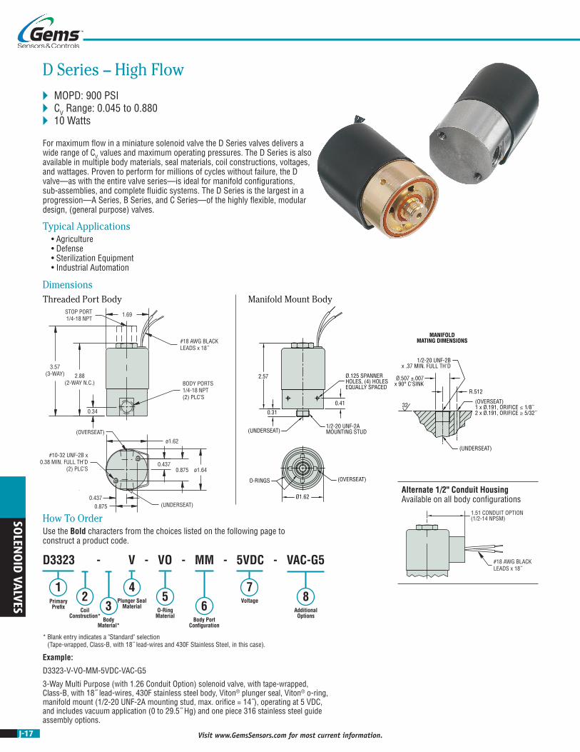
D Series – High Flow MOPD: 900 PSI CV Range: 0.045 to 0.880 10 Watts
For maximum flow in a miniature solenoid valve the D Series valves delivers a wide range of CV values and maximum operating pressures. The D Series is also available in multiple body materials, seal materials, coil constructions, voltages, and wattages. Proven to perform for millions of cycles without failure, the D valve—as with the entire valve series—is ideal for manifold configurations, sub-assemblies, and complete fluidic systems. The D Series is the largest in a progression—A Series, B Series, and C Series—of the highly flexible, modular design, (general purpose) valves.
Typical Applications • Agriculture • Defense • Sterilization Equipment • Industrial Automation
Example:
D3323-V-VO-MM-5VDC-VAC-G5
3-Way Multi Purpose (with 1.26 Conduit Option) solenoid valve, with tape-wrapped, Class-B, with 18˝ lead-wires, 430F stainless steel body, Viton® plunger seal, Viton® o-ring, manifold mount (1/2-20 UNF-2A mounting stud, max. orifice = 14˝), operating at 5 VDC, and includes vacuum application (0 to 29.5˝ Hg) and one piece 316 stainless steel guide assembly options.
D3323 - V - VO - MM - 5VDC - VAC-G5
1 45
76
823Primary
PrefixPlunger Seal
MaterialO-Ring
Material
Voltage
Body Port Configuration
Additional Options
Coil Construction*
Body Material*
How To OrderUse the Bold characters from the choices listed on the following page to construct a product code.
* Blank entry indicates a "Standard" selection (Tape-wrapped, Class-B, with 18˝ lead-wires and 430F Stainless Steel, in this case).
Ø.125 SPANNERHOLES, (4) HOLESEQUALLY SPACED
(OVERSEAT)
(UNDERSEAT)
2.57
0.31
0.41
O-RINGS
1/2-20 UNF-2AMOUNTING STUD
Ø1.62
1/2-20 UNF-2Bx .37 MIN. FULL TH'D
(UNDERSEAT)
32(OVERSEAT)1 x Ø.191, ORIFICE ≤ 1/8˝2 x Ø.191, ORIFICE ≥ 5/32˝
Ø.507 ±.007x 90° C'SINK
R.512
MANIFOLDMATING DIMENSIONS
Alternate 1/2" Conduit Housing Available on all body configurations
J-18Visit www.GemsSensors.com for most current information.
SOLE
NO
ID V
ALV
ES
Orifice MOPD(psig)
CV 1 Primary Prefix
Body Stop Body Stop Grommet Housing
Conduit Housing
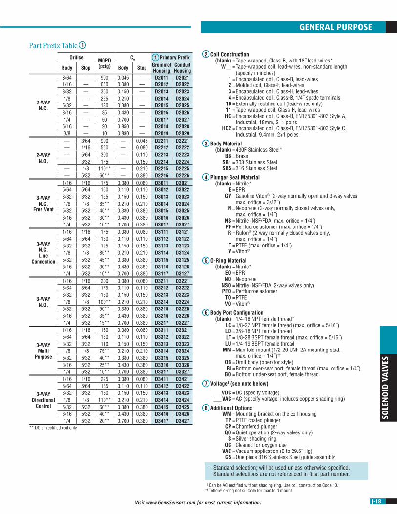
2-WAY N.C.
3/64 — 900 0.045 — D2011 D20211/16 — 650 0.080 — D2012 D20223/32 — 350 0.150 — D2013 D20231/8 — 225 0.210 — D2014 D20245/32 — 130 0.380 — D2015 D20253/16 — 85 0.430 — D2016 D20261/4 — 50 0.700 — D2017 D20275/16 — 20 0.850 — D2018 D20283/8 — 10 0.880 — D2019 D2029
2-WAY N.O.
— 3/64 900 — 0.045 D2211 D2221— 1/16 550 — 0.080 D2212 D2222— 5/64 300 — 0.110 D2213 D2223— 3/32 175 — 0.150 D2214 D2224— 1/8 110** — 0.210 D2215 D2225— 5/32 60** — 0.380 D2216 D2226
3-WAY N.C.
Free Vent
1/16 1/16 175 0.080 0.080 D3011 D30215/64 5/64 150 0.110 0.110 D3012 D30223/32 3/32 125 0.150 0.150 D3013 D30231/8 1/8 85** 0.210 0.210 D3014 D30245/32 5/32 45** 0.380 0.380 D3015 D30253/16 5/32 30** 0.430 0.380 D3016 D30261/4 5/32 10** 0.700 0.380 D3017 D3027
3-WAY N.C. Line
Connection
1/16 1/16 175 0.080 0.080 D3111 D31215/64 5/64 150 0.110 0.110 D3112 D31223/32 3/32 125 0.150 0.150 D3113 D31231/8 1/8 85** 0.210 0.210 D3114 D31245/32 5/32 45** 0.380 0.380 D3115 D31253/16 5/32 30** 0.430 0.380 D3116 D31261/4 5/32 10** 0.700 0.380 D3117 D3127
3-WAY N.O.
1/16 1/16 200 0.080 0.080 D3211 D32215/64 5/64 175 0.110 0.110 D3212 D32223/32 3/32 150 0.150 0.150 D3213 D32231/8 1/8 100** 0.210 0.210 D3214 D32245/32 5/32 50** 0.380 0.380 D3215 D32253/16 5/32 35** 0.430 0.380 D3216 D32261/4 5/32 15** 0.700 0.380 D3217 D3227
3-WAY Multi
Purpose
1/16 1/16 160 0.080 0.080 D3311 D33215/64 5/64 130 0.110 0.110 D3312 D33223/32 3/32 110 0.150 0.150 D3313 D33231/8 1/8 75** 0.210 0.210 D3314 D33245/32 5/32 40** 0.380 0.380 D3315 D33253/16 5/32 25** 0.430 0.380 D3316 D33261/4 5/32 10** 0.700 0.380 D3317 D3327
3-WAY Directional
Control
1/16 1/16 225 0.080 0.080 D3411 D34215/64 5/64 185 0.110 0.110 D3412 D34223/32 3/32 150 0.150 0.150 D3413 D34231/8 1/8 110** 0.210 0.210 D3414 D34245/32 5/32 60** 0.380 0.380 D3415 D34253/16 5/32 40** 0.430 0.380 D3416 D34261/4 5/32 20** 0.700 0.380 D3417 D3427
** DC or rectified coil only
* Standard selection; will be used unless otherwise specified. Standard selections are not referenced in final part number.
GENERAL PURPOSE
2 Coil Construction (blank) = Tape-wrapped, Class-B, with 18˝ lead-wires* W__ = Tape-wrapped coil, lead-wires, non-standard length (specify in inches) 1 = Encapsulated coil, Class-B, lead-wires 2 = Molded coil, Class-F, lead-wires 3 = Encapsulated coil, Class-H, lead-wires 4 = Encapsulated coil, Class-B, 1/4˝ spade terminals 10 = Externally rectified coil (lead-wires only) 11 = Tape-wrapped coil, Class-H, lead-wires HC = Encapsulated coil, Class-B, EN175301-803 Style A, Industrial, 18mm, 2+1 poles HC2 = Encapsulated coil, Class-B, EN175301-803 Style C, Industrial, 9.4mm, 2+1 poles
3 Body Material (blank) = 430F Stainless Steel* BB = Brass SB1 = 303 Stainless Steel SB5 = 316 Stainless Steel
4 Plunger Seal Material (blank) = Nitrile* E = EPR GV = Gasoline Viton® (2-way normally open and 3-way valves max. orifice = 3/32˝) N = Neoprene (2-way normally closed valves only, max. orifice = 1/4˝) NS = Nitrile (NSF/FDA, max. orifice = 1/4˝) PF = Perfluoroelastomer (max. orifice = 1/4˝) R = Rulon® (2-way normally closed valves only, max. orifice = 1/4˝) T = PTFE (max. orifice = 1/4˝) V = Viton®
5 O-Ring Material (blank) = Nitrile* EO = EPR NO = Neoprene NSO = Nitrile (NSF/FDA, 2-way valves only) PFO = Perfluoroelastomer TO = PTFE VO = Viton®
6 Body Port Configuration (blank) = 1/4-18 NPT female thread* LC = 1/8-27 NPT female thread (max. orifice = 5/16˝) LD = 3/8-18 NPT female thread LT = 1/8-28 BSPT female thread (max. orifice = 5/16˝) LU = 1/4-19 BSPT female thread MM = Manifold mount (1/2-20 UNF-2A mounting stud, max. orifice = 1/4˝)†† OB = Omit body (operator style) BI = Bottom over-seat port, female thread (max. orifice = 1/4˝) BO = Bottom under-seat port, female thread
7 Voltage† (see note below)
___VDC = DC (specify voltage) ___VAC = AC (specify voltage; includes copper shading ring)
8 Additional Options WM = Mounting bracket on the coil housing TP = PTFE coated plunger CP = Chamfered plunger QO = Quiet operation (2-way valves only) S = Silver shading ring OC = Cleaned for oxygen use VAC = Vacuum application (0 to 29.5˝ Hg) G5 = One piece 316 Stainless Steel guide assembly
1Part Prefix Table
† Can be AC rectified without shading ring. Use coil construction Code 10. †† Teflon® o-ring not suitable for manifold mount.

J-19 Visit www.GemsSensors.com for most current information.
SOLEN
OID
VALVES
ø1.03
ø.99
1.97
0.27
“IN” (UNDERSEAT)
“OUT” (OVERSEAT)
32.5°
#8-32 UNC-2B x0.25 MIN. FULL TH’DON A ø.735 B.C.(2) PLC’S
BODY PORTS1/8-27 NPT(2) PLC’S
#20 AWG BLACKLEADS x 18˝
0.28
1/4-28 UNF-2AMOUNTING STUD
Ø.99
(OVERSEAT)
Ø.125 SPANNER HOLES, (4) HOLESEQUALLY SPACED
0.17
1.69 1/4-28 UNF-2Bx 0.33 MIN. FULL TH'D
32
(UNDERSEAT)
32
Ø.359 ±.002
Ø.256 MAX.x 90° C'SINK
R.256
0.035 ±0.002
MANIFOLDMATING DIMENSIONS
(OVERSEAT)1 x Ø.104, ORIFICE ≤ 5/64˝2 x Ø.104, ORIFICE ≥ 3/32˝(UNDERSEAT)
O-RINGS
1.11 CONDUIT OPTION(1/2-14 NPSM)
Alternate 1/2" Conduit Housing Available on all body configurations
DimensionsThreaded Port Body Manifold Mount Body
AS Series MOPD: 110 PSI (Plastic Body) or 150 PSI (Metal Body) CV Range: 0.020 to 0.300 4.5 Watts (Plastic Body) or 7 Watts (Metal Body)
The AS Series is a 2-way isolation valve, designed to control the flow of various aggressive liquids and gases with several body and diaphragm materials. With a modular design, the AS offers performance flexibility and the protection your media needs from the solenoid’s internal components. Numerous port configurations, voltage options, and coil constructions enable the AS Series to be a truly versatile miniature inert isolation valve, easily integrated into any complex or demanding system.
Typical Applications • Analytical Instruments • Clinical Diagnostic Analyzers • Bio-Instrumentation
Example:
AS2022-10-SB-NS-BD-110/50/60VAC-WM
2-Way N.C. (1/2˝ conduit housing) solenoid valve, with externally rectified coil (lead-wires only), 304 stainless steel body, nitrile (NSF/FDA) diaphragm seal, #10-32 female straight thread, operating at 110/50/60 Volt AC with rectified coil and mounting bracket.
AS2022 - 10 - SB - NS - BD - 110/50/60VAC - WM
12
34
56
7Primary Prefix Coil
ConstructionBody
Material2
Diaphragm Seal
Material Body Port Configuration
Voltage
Additional Options
How To OrderUse the Bold characters from the choices listed on the following page to construct a product code.
Notes1. After the Primary Prefix, any "-Code" may be blank when standard
(blank) selections are specified.2. The Body Material option code, when specified, supercedes the
standard body material indicated by the Primary Prefix.
J-20Visit www.GemsSensors.com for most current information.
SOLE
NO
ID V
ALV
ES
Body Material
Orifice MOPD(psig)
Max Back Pressure
CV 1 Primary Prefix
Body Body Grommet Housing
Conduit Housing
303 Stainless Steel1
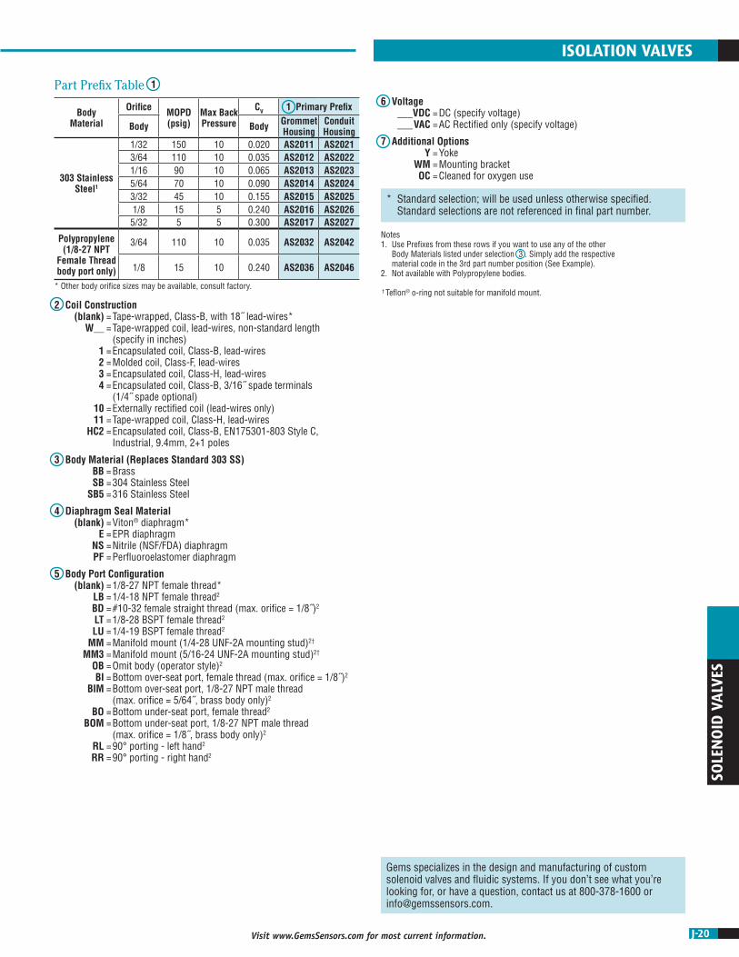
1/32 150 10 0.020 AS2011 AS20213/64 110 10 0.035 AS2012 AS20221/16 90 10 0.065 AS2013 AS20235/64 70 10 0.090 AS2014 AS20243/32 45 10 0.155 AS2015 AS20251/8 15 5 0.240 AS2016 AS20265/32 5 5 0.300 AS2017 AS2027
Polypropylene (1/8-27 NPT
Female Thread body port only)
3/64 110 10 0.035 AS2032 AS2042
1/8 15 10 0.240 AS2036 AS2046
* Other body orifice sizes may be available, consult factory.
* Standard selection; will be used unless otherwise specified. Standard selections are not referenced in final part number.
Gems specializes in the design and manufacturing of custom solenoid valves and fluidic systems. If you don’t see what you’re looking for, or have a question, contact us at 800-378-1600 or [email protected].
ISOLATION VALVES
6 Voltage ___VDC = DC (specify voltage) ___VAC = AC Rectified only (specify voltage)
7 Additional Options Y = Yoke WM = Mounting bracket OC = Cleaned for oxygen use
2 Coil Construction (blank) = Tape-wrapped, Class-B, with 18˝ lead-wires* W__ = Tape-wrapped coil, lead-wires, non-standard length (specify in inches) 1 = Encapsulated coil, Class-B, lead-wires 2 = Molded coil, Class-F, lead-wires 3 = Encapsulated coil, Class-H, lead-wires 4 = Encapsulated coil, Class-B, 3/16˝ spade terminals (1/4˝ spade optional) 10 = Externally rectified coil (lead-wires only) 11 = Tape-wrapped coil, Class-H, lead-wires HC2 = Encapsulated coil, Class-B, EN175301-803 Style C, Industrial, 9.4mm, 2+1 poles
3 Body Material (Replaces Standard 303 SS) BB = Brass SB = 304 Stainless Steel SB5 = 316 Stainless Steel
4 Diaphragm Seal Material (blank) = Viton® diaphragm* E = EPR diaphragm NS = Nitrile (NSF/FDA) diaphragm PF = Perfluoroelastomer diaphragm
5 Body Port Configuration (blank) = 1/8-27 NPT female thread* LB = 1/4-18 NPT female thread2 BD = #10-32 female straight thread (max. orifice = 1/8˝)2 LT = 1/8-28 BSPT female thread2 LU = 1/4-19 BSPT female thread2 MM = Manifold mount (1/4-28 UNF-2A mounting stud)2† MM3 = Manifold mount (5/16-24 UNF-2A mounting stud)2† OB = Omit body (operator style)2 BI = Bottom over-seat port, female thread (max. orifice = 1/8˝)2 BIM = Bottom over-seat port, 1/8-27 NPT male thread (max. orifice = 5/64˝, brass body only)2 BO = Bottom under-seat port, female thread2 BOM = Bottom under-seat port, 1/8-27 NPT male thread (max. orifice = 1/8˝, brass body only)2 RL = 90° porting - left hand2 RR = 90° porting - right hand2
1Part Prefix Table
Notes1. Use Prefixes from these rows if you want to use any of the other
Body Materials listed under selection 3 . Simply add the respective material code in the 3rd part number position (See Example).
2. Not available with Polypropylene bodies.
† Teflon® o-ring not suitable for manifold mount.

J-21 Visit www.GemsSensors.com for most current information.
SOLEN
OID
VALVES
ø1.22
ø.99
#8-32 UNC-2B x0.25 MIN. FULL TH’D
ON A ø.735 B.C.(2) PLC’S
0.80
2.27
0.27
#18 AWG BLACKLEADS x 18˝
BODY PORTS1/8-27 NPT(2) PLC’S
“IN” (UNDERSEAT)
“OUT” (OVERSEAT)
32.5°
1.26 CONDUIT OPTION(1/2-14 NPSM)
0.25
5/16-24 UNF-2AMOUNTING STUD
Ø.99
O-RINGS
Ø.125 SPANNER HOLES, (4) HOLES EQUALLY SPACED
0.24
2.02
(OVERSEAT)
5/16-24 UNF-2Bx 0.28 MIN. FULL TH'D
(UNDERSEAT)
32
Ø.319 ±.007 MAX.x 90° C'SINK
R.310
(OVERSEAT)2 x Ø.094, ORIFICE ≤ 1/8˝3 x Ø.094, ORIFICE ≥ 5/32˝
MANIFOLDMATING DIMENSIONS
(UNDERSEAT)0.25
5/16-24 UNF-2AMOUNTING STUD
Ø.99
O-RINGS
Ø.125 SPANNER HOLES, (4) HOLES EQUALLY SPACED
0.24
2.02
(OVERSEAT)
5/16-24 UNF-2Bx 0.28 MIN. FULL TH'D
(UNDERSEAT)
32
Ø.319 ±.007 MAX.x 90° C'SINK
R.310
(OVERSEAT)2 x Ø.094, ORIFICE ≤ 1/8˝3 x Ø.094, ORIFICE ≥ 5/32˝
MANIFOLDMATING DIMENSIONS
(UNDERSEAT)
DimensionsThreaded Port Body Manifold Mount Body
Alternate 1/2" Conduit Housing Available on all body configurations
BS Series – Higher Flow MOPD: 150 PSI (Plastic Body) or 150 PSI (Metal Body) CV Range: 0.035 to 0.300 4.5 Watts (Plastic Body) or 7 Watts (Metal Body)
The BS Series is a 2-way, high flow, isolation valve that is designed to be virtually impervious to chemical attack and to protect high purity media. When your media cannot come in contact with any metallic materials, this highly versatile, modular valve delivers the protection you need for accurate and reliable flow control for millions of cycles. With a variety of body, and diaphragm materials, plus numerous port configurations, voltage options, and coil constructions, the BS Series is truly a miniature inert isolation valve that can be built to your exact applications requirements.
Typical Applications • Remediation Equipment • Clinical Chemistry Equipment • Analytical Instrumentation
Example:
BS2035-W25-E-28VDC
2-Way N.C. Polypropylene (grommet housing, 1/8-27 NPT female thread only) solenoid valve, with 25˝ tape-wrapped coil, lead-wires, non-standard length, EPR diaphragm seal, 1/8-27 NPT female thread, operating at 28 VDC.
BS2035 - W25 - E - 28VDC
12
46
75
3Primary Prefix Coil
Construction
Diaphragm Seal Material
Voltage
Additional Options*
Body Port Configuration*
Body Material*
How To OrderUse the Bold characters from the choices listed on the following page to construct a product code.
* Blank entry indicates a "Standard" selection (1/8-27NPT female thread, in this case).

J-22Visit www.GemsSensors.com for most current information.
SOLE
NO
ID V
ALV
ES
Body Material
Orifice MOPD(psig)
Max Back Pressure
CV 1 Primary Prefix
Body Body Grommet Housing
Conduit Housing
303 Stainless Steel1
3/64 150 15 0.035 BS2010 BS20201/16 110 10 0.065 BS2011 BS20215/64 85 10 0.090 BS2012 BS20223/32 70 10 0.155 BS2013 BS20237/64 25 10 0.200 BS2014 BS20241/8 10 5 0.240 BS2015 BS20255/32 5 5 0.300 BS2016 BS2026
Polypropylene (1/8-27 NPT
Female Thread body port only)
3/64 150 15 0.035 BS2030 BS2040
1/8 10 5 0.240 BS2035 BS2045
* Other body orifice sizes may be available, consult factory.
* Standard selection; will be used unless otherwise specified. Standard selections are not referenced in final part number.
ISOLATION VALVES
6 Voltage ___VDC = DC (specify voltage) ___VAC = AC Rectified only (specify voltage)
7 Additional Options WM = Mounting bracket OC = Cleaned for oxygen use
2 Coil Construction (blank) - Tape-wrapped, Class-B, with 18˝ lead-wires* W__ = Tape-wrapped coil, lead-wires, non-standard length (specify in inches) 1 = Encapsulated coil, Class-B, lead-wires 3 = Encapsulated coil, Class-H, lead-wires 4 = Encapsulated coil, Class-B, 1/4˝ spade terminals (3/16˝ spade optional) 10 = Externally rectified coil (lead-wires only) 11 = Tape-wrapped coil, Class-H, lead-wires HC2 = Encapsulated coil, Class-B, EN175301-803 Style C, Industrial, 9.4mm, 2+1 poles
3 Body Material (Replaces Standard 303 SS) BB = Brass SB = 304 Stainless Steel SB5 = 316 Stainless Steel
4 Diaphragm Seal Material (blank) = Viton® diaphragm* E = EPR diaphragm NS = Nitrile (NSF/FDA) diaphragm PF = Perfluoroelastomer diaphragm
5 Body Port Configuration (blank) = 1/8-27 NPT female thread* LB = 1/4-18 NPT female thread2 BD = #10-32 female straight thread (max. orifice = 1/8˝)2 LT = 1/8-28 BSPT female thread2 LU = 1/4-19 BSPT female thread2 MM = Manifold mount (1/4-28 UNF-2A mounting stud)†2 MM3 = Manifold mount (5/16-24 UNF-2A mounting stud)†2 OB = Omit body (operator style)2 BI = Bottom over-seat port, female thread (max. orifice = 1/8˝)2 BIM = Bottom over-seat port, 1/8-27 NPT male thread (max. orifice = 5/64˝, brass body only)2 BO = Bottom under-seat port, female thread2 BOM = Bottom under-seat port, 1/8-27 NPT male thread (max. orifice = 1/8˝, brass body only)2 RL = 90° porting - left hand2 RR = 90° porting - right hand2
1Part Prefix Table
Notes1. Use Prefixes from these rows if you want to use any of the other
Body Materials listed under selection 3 . Simply add the respective material code in the 3rd part number position (See Example).
2. Not available with Polypropylene bodies.
† Teflon® o-ring not suitable for manifold mount.
Gems specializes in the design and manufacturing of custom solenoid valves and fluidic systems. If you don’t see what you’re looking for, or have a question, contact us at 800-378-1600 or [email protected].

J-23 Visit www.GemsSensors.com for most current information.
SOLEN
OID
VALVES
ø1.22
ø1.18
0.343
0.687
0.44
2.35
#18 AWG TEFLONLEADS x 18˝
BODY PORTS1/8-27 NPT(2) PLC’S
1.26 CONDUIT(FILLED w/EPOXY)
#10-32 UNF-2B x0.25 MIN. FULL TH’D(2) PLC’S
0.2970.593
“OUT” (UNDERSEAT)
“IN” (OVERSEAT)
ø1.22
ø.99
#8-32 UNC-2B x0.25 MIN. FULL TH’D
ON A ø.735 B.C.(2) PLC’S
0.270.80
2.27
“IN” (OVERSEAT)
“OUT” (UNDERSEAT)
32.5°
#18 AWG SILICONELEADS x 18˝
BODY PORTS1/8-27 NPT(2) PLC’S
1.26 CONDUIT(FILLED w/EPOXY)
B-Cryo Series MOPD: 900 PSI CV Range: 0.045 to 0.440 9 Watts
The B-Cryo Series is a 2-way miniature Cryogenic valve designed and built for service down to -320°F (-196°C) in applications needing a CV between 0.045 and 0.440. Depending on your temperature requirements, the B-Cryo Series can be configured for liquid nitrogen (LN2), liquid carbon dioxide (LCO2), and other extreme temperature media. PTFE coated plungers, 316 Stainless Steel guide tubes and plunger springs, encapsulated coils, and PTFE or Rulon® seat seals produce a truly robust Cryogenic valve for applications requiring high cycle life and media temperature control.
Typical Applications • Environmental Chambers • Food Processing • Laser Surgical Equipment • Semiconductor Manufacturing
DimensionsLN2–Liquid Nitrogen LCO2–Liquid Carbon Dioxide
B2062 - LN2 - LB - 120/50/60VAC
16
27
Primary Prefix Model
Body Port Configuration
Voltage
How To OrderUse the Bold characters from the choices listed on the following page to construct a product code.
* Blank entry indicates a "Standard" selection (430F Stainless Steel, Rulon® and Variseal®, in this case).
34
5 8
Body Material*
Plunger Seal Material*
O-Ring Material*
Additional Options*
Example:
B2062-LN2-LB-120/50/60VAC
2-Way N.C. Liquid Nitrogen Class-H Encapsulated Coil with lead-wires, conduit filled housing solenoid valve, with 430F stainless steel body, Rulon® plunger seal, Variseal® o-ring, 1/4-18 NPT female thread, operating at 120/50/60 Volt AC.
J-24Visit www.GemsSensors.com for most current information.
SOLE
NO
ID V
ALV
ES
1 Primary Prefix
Orifice MOPD(psig)
CV Class H, Encapsulated Coils
Body Body Lead Wires—Filled Conduit Housing
Lead Wires—Unfilled Conduit Housing
Lead Wires—Grommet Housing
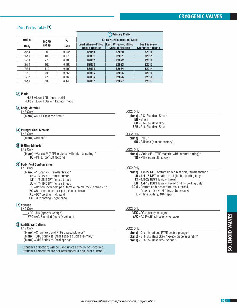
3/64 900 0.045 B2060 B2020 B20101/16 405 0.075 B2061 B2021 B20115/64 270 0.105 B2062 B2022 B20123/32 160 0.160 B2063 B2023 B20137/64 110 0.190 B2064 B2024 B20141/8 80 0.255 B2065 B2025 B20155/32 65 0.365 B2066 B2026 B20163/16 30 0.440 B2067 B2027 B2017
* Standard selection; will be used unless otherwise specified. Standard selections are not referenced in final part number.
CRYOGENIC VALVES
1Part Prefix Table
2 Model -LN2 = Liquid Nitrogen model -LCO2 = Liquid Carbon Dioxide model
8 Additional Options LN2 Only (blank) = Chamfered and PTFE coated plunger* (blank) = 316 Stainless Steel 1-piece guide assembly* (blank) = 316 Stainless Steel spring*
LCO2 Only (blank) = Chamfered and PTFE coated plunger* (blank) = 316 Stainless Steel 1-piece guide assembly* (blank) = 316 Stainless Steel spring*
7 Voltage LN2 Only ___VDC = DC (specify voltage) ___VAC = AC Rectified (specify voltage)
LCO2 Only ___VDC = DC (specify voltage) ___VAC = AC Rectified (specify voltage)
6 Body Port Configuration LN2 Only (blank) = 1/8-27 NPT female thread* LB = 1/4-18 NPT female thread LT = 1/8-28 BSPT female thread LU = 1/4-19 BSPT female thread BI = Bottom over-seat port, female thread (max. orifice = 1/8˝) BO = Bottom under-seat port, female thread RL = 90° porting - left hand RR = 90° porting - right hand
LCO2 Only (blank) = 1/8-27 NPT, bottom under-seat port, female thread* LB = 1/4-18 NPT female thread (in-line porting only) LT = 1/8-28 BSPT female thread LU = 1/4-19 BSPT female thread (in-line porting only) BOM = Bottom under-seat port, male thread (max. orifice = 1/8˝, brass body only) IL = Inline porting, 180° apart
5 O-Ring Material LN2 Only (blank) = Variseal® (PTFE material with internal spring)* TO = PTFE (consult factory)
LCO2 Only (blank) = Variseal® (PTFE material with internal spring)* TO = PTFE (consult factory)
4 Plunger Seal Material LN2 Only (blank) = Rulon®*
LCO2 Only (blank) = PTFE* MQ = Silicone (consult factory)
3 Body Material LN2 Only (blank) = 430F Stainless Steel*
LCO2 Only (blank) = 303 Stainless Steel* BB = Brass SB = 304 Stainless Steel SB5 = 316 Stainless Steel

J-25 Visit www.GemsSensors.com for most current information.
SOLEN
OID
VALVES
ø1.62
0.34
2.88
1.68
#18 AWG PTFELEADS x 18˝
BODY PORTS1/4-18 NPT(2) PLC’S
1.51 CONDUIT(FILLED w/ EPOXY)
1.52FLATS
“OUT” (UNDERSEAT)
“IN” (OVERSEAT)
#10-32 UNF-2B x0.38 MIN. FULL TH’D
ON A ø1.237 B.C.(2) PLC’S
45°
D-Cryo Series MOPD: 1000 PSI CV Range: 0.040 to 0.770 15 Watts
The D-Cryo Series is a 2-way, high flow, miniature Cryogenic valve designed and built for service down to –320°F (-196°C). Depending on your temperature requirements, the D-Cryo Series can be configured for liquid nitrogen (LN2), liquid carbon dioxide (LCO2), and other extreme temperature media. PTFE coated plungers, 316 Stainless Steel guide tubes and plunger springs, encapsulated coils, and PTFE or Rulon® seat seals produce a truly robust Cryogenic valve for applications requiring high cycle life and media temperature control.
Typical Applications • Environmental Chambers • Food Processing • Laser Surgical Equipment • Semiconductor Manufacturing
D2062 - LN2 - LT - 12VDC
16
27
Primary Prefix Model
Body Port Configuration
Voltage
How To OrderUse the Bold characters from the choices listed on the following page to construct a product code.
* Blank entry indicates a "Standard" selection (430F Stainless Steel, Rulon® and Variseal®, in this case).
34
5 8
Body Material*
Plunger Seal Material*
O-Ring Material*
Additional Options*
Example:
D2062-LN2-LT-12VDC
2-Way N.C. Liquid Nitrogen Class-H Encapsulated Coil with lead-wires, conduit filled housing solenoid valve, with 430F stainless steel body, Rulon® plunger seal, Variseal® o-ring, 1/8-28 BSPT female thread, operating at 12 DC with rectified coil.
DimensionsLN2–Liquid Nitrogen LCO2–Liquid Carbon Dioxide
0.34
2.88
1.68
1.51 CONDUIT(FILLED w/EPOXY)
BODY PORTS1/4-18 NPT(2) PLC'S
#18 AWG SILICONELEADS x 18"
1.52FLATS
Ø1.62
#10-32 UNF-2B x0.38 MIN. FULL TH'D
ON A Ø1.237 B.C.(2) PLC'S
"OUT" (UNDERSEAT)
"IN" (OVERSEAT)
45°
J-26Visit www.GemsSensors.com for most current information.
SOLE
NO
ID V
ALV
ES
1 Primary Prefix
Orifice MOPD(psig)
CV Class H, Encapsulated Coils
Body Body Lead Wires—Filled Conduit Housing
Lead Wires—Unfilled Conduit Housing
Lead Wires—Grommet Housing
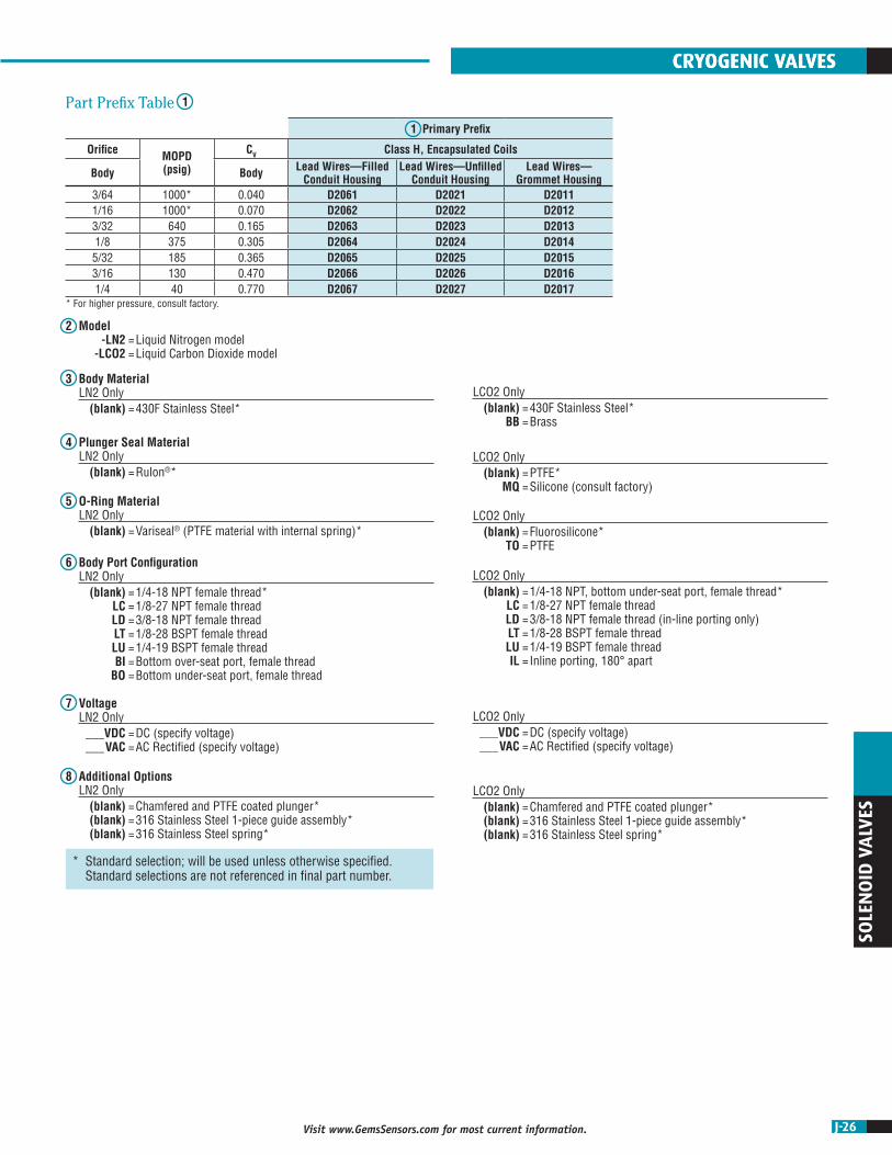
3/64 1000* 0.040 D2061 D2021 D20111/16 1000* 0.070 D2062 D2022 D20123/32 640 0.165 D2063 D2023 D20131/8 375 0.305 D2064 D2024 D20145/32 185 0.365 D2065 D2025 D20153/16 130 0.470 D2066 D2026 D20161/4 40 0.770 D2067 D2027 D2017
* For higher pressure, consult factory.
* Standard selection; will be used unless otherwise specified. Standard selections are not referenced in final part number.
CRYOGENIC VALVES
1Part Prefix Table
2 Model -LN2 = Liquid Nitrogen model -LCO2 = Liquid Carbon Dioxide model
8 Additional Options LN2 Only (blank) = Chamfered and PTFE coated plunger* (blank) = 316 Stainless Steel 1-piece guide assembly* (blank) = 316 Stainless Steel spring*
LCO2 Only (blank) = Chamfered and PTFE coated plunger* (blank) = 316 Stainless Steel 1-piece guide assembly* (blank) = 316 Stainless Steel spring*
7 Voltage LN2 Only ___VDC = DC (specify voltage) ___VAC = AC Rectified (specify voltage)
LCO2 Only ___VDC = DC (specify voltage) ___VAC = AC Rectified (specify voltage)
6 Body Port Configuration LN2 Only (blank) = 1/4-18 NPT female thread* LC = 1/8-27 NPT female thread LD = 3/8-18 NPT female thread LT = 1/8-28 BSPT female thread LU = 1/4-19 BSPT female thread BI = Bottom over-seat port, female thread BO = Bottom under-seat port, female thread
LCO2 Only (blank) = 1/4-18 NPT, bottom under-seat port, female thread* LC = 1/8-27 NPT female thread LD = 3/8-18 NPT female thread (in-line porting only) LT = 1/8-28 BSPT female thread LU = 1/4-19 BSPT female thread IL = Inline porting, 180° apart
5 O-Ring Material LN2 Only (blank) = Variseal® (PTFE material with internal spring)*
LCO2 Only (blank) = Fluorosilicone* TO = PTFE
4 Plunger Seal Material LN2 Only (blank) = Rulon®*
LCO2 Only (blank) = PTFE* MQ = Silicone (consult factory)
3 Body Material LN2 Only (blank) = 430F Stainless Steel*
LCO2 Only (blank) = 430F Stainless Steel* BB = Brass
CRYOGENIC VALVES
J-27 Visit www.GemsSensors.com for most current information.
SOLEN
OID
VALVES
ø1.214
0.78 GROMMET
0.900
0.274
2.69
#20 AWG TFE (UL #1180)12˝ LONG (3) PLC’S
– GREEN (FOR LATCHING)+ BLACK (COMMON)– RED (FOR UNLATCHING)
1/8 NPT PORT(2) PLC’S
FLUXPLATE
“EXH” (STOP PORT)#10-32 UNF–2B
MAGNET
“IN” (U/S PORT)1/8-27 NPT
#8-32 UNC-2B x0.250 FULL MIN. TH’DON 0.735 B.C. (2) PLC’S
“CYL” (O/S PORT)1/8-27 NPT
32.5°ø.989
ø1.214
0.78 GROMMET
0.240.245
2.40
#20 AWG TFE (UL #1180)18˝ LONG (3) PLC’S
+ GREEN (FOR LATCHING)– BLACK (COMMON)+ RED (FOR UNLATCHING)
ø.125 SPANNER HOLES,(4) HOLES EQUALLY SPACED
FLUXPLATE
“EXH” (STOP PORT)#10-32 UNF–2B
MAGNET
“IN” (U/S PORT)O-RINGS
(NITRILE)
5/16-24 UNF-2A STUD
“CYL” (O/S PORT)ø.089 THRU(4) PLC’S ON ø.623 B.C.
ø.989
1.26 CONDUIT OPTION(1/2-14 NPSM)
DimensionsThreaded Port Body Manifold Mount Body
BL Series – Latching Valve 2 Way or 3 Way Valves Low Power Requirements MOPD: 100 PSI Dual Diode Protection Optional
The BL series latching valve allows the user to pulse the valve and have it change state. The voltage does not need to be constantly applied in order to hold it in a state. These valves are ideal for controlling larger pneumatic valves in remote applications where power is limited or when the temperature of the media cannot be impacted as it flows through the valve. The larger pneumatic valves can close and open large pipes and these latching valves control them. The term Latch refers to the valve in the open state where supply pressure goes to the external valve. The unlatched state is when the supply is cut off and the external valve is exhausted to ambient.
Typical Applications • Natural Gas Plunger Lifts • Gas Chromatography • Natural Gas Separators • Irrigation Systems
Alternate 1/2" Conduit Housing Available on all body configurations
Example:
BL3113-1-BB-H-NBO-LC-C202-WGR-N
3-Way Latching valve, 18˝ epoxy coil, brass body, Hydrin® seal, Nitrile® o-ring, 1/8˝ NPT body port, free vent 6 Vdc coil, White/Common, Green/Latch, Red/Unlatch negative pulse leads.
BL3113 - 1 - BB - H - NBO - LC - - C202 - WGR-N
12
45
78
3 6 9Primary Prefix Coil
Construction
Plunger Seal Material
O-Ring Material
Exhaust Port*
Voltage
Body Material
Body Port Configuration
Wire Color Codes
How To OrderUse the Bold characters from the choices listed on the following page to construct a product code.
* Blank entry indicates a "Standard" selection (#10-32 female thread, in this case).

J-28Visit www.GemsSensors.com for most current information.
* Standard selection; will be used unless otherwise specified. Standard selections are not referenced in final part number.
SOLE
NO
ID V
ALV
ES
Orifice MOPD(psi)
CV1 Primary Prefix
Body Stop Body Stop Grommet Housing Unfilled Conduit Housing
3-WAY1/32 3/64 100 0.018 0.040 BL3111 BL31211/16 1/16 50 0.070 0.070 BL3113 BL3123
2-WAY
1/16 — 240 0.065 — BL2011 BL20215/64 — 180 0.09 — BL2012 BL20223/32 — 150 0.155 — BL2013 BL20237/64 — 120 0.2 — BL2014 BL20241/8 — 90 0.24 — BL2015 BL20255/32 — 60 0.3 — BL2016 BL20263/16 — 30 0.43 — BL2017 BL2027
LATCHING VALVES
1Part Prefix Table
2 Coil Construction 1 = Encapsulated Coil, Class-B (130°C), Lead Wires 18˝ Long, #20 AWG 2 = Encapsulated Coil, Class-F (155°C), Lead Wires 18˝ Long, #20 AWG
3 Body Material BB = Brass SB1 = 303 Stainless Steel SB5 = 316 Stainless Steel
4 Plunger Seal Material H = Hydrin® V = Viton®
PF = Perfluoroelastomer
5 O-Ring Material NBO = Nitrile® VO = Viton®
PFO = Perfluoroelastomer
6 Body Port Configuration LC = 1/8˝ NPT female ports LD = 1/4˝ NPT female ports MM3 = Manifold-Mount (5/16˝ thread stud)
7 Exhaust Port (blank) = #10-32 female thread* AB = 1/8˝ Brass Barb Fitting AD = 1/8˝ NPT Brass Adapter
8 Voltage C202 = 6 VDC, 7 Watts Latching, 5 Watts Unlatching C203 = 12 VDC, 9 Watts Latching, 7 Watts Unlatching C204 = 24 VDC, 9 Watts Latching, 7 Watts Unlatching C202D = 6 VDC, 7 Watts Latching, 5 Watts Unlatching with internal diodes C203D = 12 VDC, 9 Watts Latching, 7 Watts Unlatching with internal diodes C204D = 24 VDC, 9 Watts Latching, 7 Watts Unlatching with internal diodes
9 Wire Color Codes WGR-N = White common (+), Green latch (-), Red Unlatch (-) BRG-P = Black common (-), Red latch (+), Green Unlatch (+) BGR-N = Black common (+), Green latch (-), Red Unlatch (-)
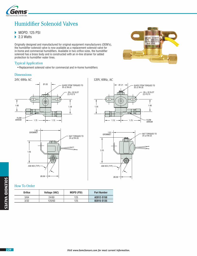
J-29 Visit www.GemsSensors.com for most current information.
SOLEN
OID
VALVES
Ø1.03
1.08
1.75 1.15
1.29
1.95
.438 HEX (TYP.)
Ø0.99
Ø1.21
1.29
1.15 1.75
1.08
2.25
.438 HEX (TYP.)
Ø0.99
GUIDE STEM TORQUED TO35 ±2 IN-LB.
.39 x .20 SLOT(2) PLC'S
FLOWARROW
1.80GROMMET
NUT TORQUED TO24 ±2 IN-LB.
GUIDE STEM TORQUED TO35 ±2 IN-LB.
.39 x .20 SLOT(2) PLC'S
FLOWARROW
NUT TORQUED TO24 ±2 IN-LB.
1.91GROMMET
Dimensions24V, 60Hz AC 120V, 60Hz, AC
Humidifier Solenoid Valves MOPD: 125 PSI 2.3 Watts
Originally designed and manufactured for original equipment manufacturers (OEM’s), the humidifier solenoid valve is now available as a replacement solenoid valve for in-home and commercial humidifiers. Available in two orifice sizes, the humidifier solenoid has a brass body and is constructed with an in-line strainer for added protection to humidifier water lines.
Typical Application • Replacement solenoid valve for commercial and in-home humidifiers
How To Order
Orifice Voltage (VAC) MOPD (PSI) Part Number
3/64 24/60 125 A2012-S1503/32 120/60 125 B2015-S135
J-30Visit www.GemsSensors.com for most current information.
SOLE
NO
ID V
ALV
ES
NOTES
HUMIDIFIER VALVES

J-31 Visit www.GemsSensors.com for most current information.
SOLEN
OID
VALVES
Manifold AssembliesGems Valve Engineers specialize in working with OEMs to design and manufacture integrated valve and manifold assemblies to meet most any fluidic system requirements. Our expert team of field and in-house engineers can deliver AutoCAD® or SolidWorks drawings in days for easy integration into OEM equipment. Whether it is a single or multiple position manifold–made from plastic, aluminum, brass or stainless steel–final systems are delivered completely assembled, tested, and ready for installation into your equipment.
Gems Manifold Assemblies offer features you require, in a compact package, at a competitive price. Integrated manifold assemblies provide:
• Simplified fluidic systems • Decreased number of potential leak paths • Reduction in the amount of mounting hardware • Reduced quantity of fittings and tubing via common passages • Compact package • Design opportunity for multiple valve configurations to handle complex and precise flow control • Reduced labor content required by OEMs • Easy valve maintenance or replacement
All Gems valve families can be integrated into a manifold system. Contact your Gems Valve Engineer for a manifold assembly that will fulfill all of your application requirements. Contact us at 800-378-1600 or [email protected].
Fluidic SystemsPurchasing a complete fluidic system through Gems eliminates the time and effort of multiple purchase orders and reduces receiving, inspection, and coordination of different parts down to a single assembly. Plus, buying from a single source gives OEMs one contact point for design changes, expediting, and warranty questions.
Gems valve engineers and manufacturing have a 50-year history of working with OEMs to develop, design, and manufacture their complex fluidic systems; from simple wiring harnesses and connectors to plug and play sub-assemblies and additional integrated fluidic components.
Designing and purchasing a complete turnkey fluidic system from Gems Sensors & Controls has many advantages.
• Receiving a complete 100% tested system that can be installed directly into your end product • Reducing the number of suppliers required • Decreasing the assembly of numerous third-party parts • Minimizing the number of potential leak-points by eliminating tubing and fittings • Reducing multiple components into a smaller and simplified final system
Our team of experts can integrate:
• Multiple valve types, including 3rd party manufacturers, into one assembly • Numerous tube and pipe fittings • Various electrical terminations • Sensors/Switches/Gauges: • Pressure switch, transducer or gauge • Fluid flow sensor • Fluid level sensor • Temperature switch or transducer • Inline media filters • Heaters and thermistors
Contact your Gems Valve Engineer for a fluidic system that will fulfill all of your application requirements. Contact us at 800-378-1600 or [email protected].
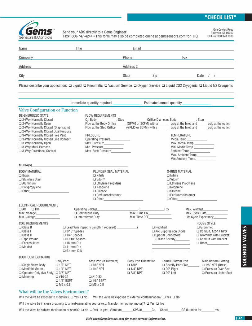
J-32Visit www.GemsSensors.com for most current information.
SOLE
NO
ID V
ALV
ES
Please describe your application: q Liquid q Pneumatic q Vacuum Service q Oxygen Service q Liquid CO2 Cryogenic q Liquid N2 Cryogenic
Immediate quantity required Estimated annual quantity
Valve Configuration or FunctionDE-ENERGIZED STATE FLOW REQUIREMENTS q 2-Way Normally Closed CV: Body____________, Stop____________ Orifice Diameter: Body____________, Stop____________ q 2-Way Normally Open Flow at the Body Orifice______ (GPM0 or SCFM) with a______ psig at the Inlet, and______ psig at the outlet q 2-Way Normally Closed (Diaphragm) Flow at the Stop Orifice______ (GPM0 or SCFM) with a______ psig at the Inlet, and______ psig at the outlet q 2-Way Normally Closed Dual Purpose q 3-Way Normally Closed Free Vent PRESSURE TEMPERATURE q 3-Way Normally Closed Line Connect Operating Pressure____________ Media Temp.____________ q 3-Way Normally Open Max. Pressure____________ Max. Media Temp.____________ q 3-Way Multi-Purpose Min. Pressure____________ Min. Media Temp.____________ q 3-Way Directional Control Max. Back Pressure____________ Ambient Temp.____________ Max. Ambient Temp____________ Min Ambient Temp.____________
MEDIA(S)__________________________________________________________
BODY MATERIAL PLUNGER SEAL MATERIAL O-RING MATERIAL q Brass q Nitrile q Nitrile q Stainless Steel q Viton® q Viton® q Aluminum q Ethylene Propylene q Ethylene Propylene q Polypropylene q Neoprene q Neoprene q Other________________________ q Silicone q Silicone q Perfluoroelastomer q Perfluoroelastomer q Other________________________ q Other________________________
ELECTRICAL REQUIREMENTS q AC q DC Operating Voltage________________________, (_______________Hz) Max. Wattage_______________ Max. Voltage______________ q Continuous Duty Max. Time ON______________ Max. Cycle Rate_____________ Min. Voltage_______________ q Intermittent Duty Min. Time OFF______________ Life Cycle Expectancy________
COIL REQUIREMENTS HOUSE STYLE q Class B q Lead Wire (Specify Length If required) ____________) q Rectified q Grommet q Class F q 3/16” Spades q Arc Suppression Diode q Conduit, 1/2-14 NPS q Class H q 1/4” Spades q Special Connectors q Grommet with Bracket q Tape Wound q 0.110” Spades (Please Specify)________ q Conduit with Bracket q Encapsulated q 18 mm DIN _______________________ q Other_____________ q Molded q 11 mm DIN _______________________ q 9.4 mm DIN _______________________
BODY CONFIGURATION Body Port Stop Port (If Different) Body Port Orientation Female Bottom Port Male Bottom Porting q Single Valve Body q 1/8” NPT q 1/8” NPT q 180° q Specify Port Size_______ q 1/8” NPT (Brass) q Manifold Mount q 1/4” NPT q 1/4” NPT q 1/4” NPT q 90° Right q Pressure Over-Seat q Operator Only (No Body) q 3/8” NPT q 3/8” NPT q 90° Left q Pressure Under Seat q Metering q #10-32 q #10-32 q 1/8” BSPT q 1/8” BSPT q M5 x 0.8 q M5 x 0.8
What will be the Valves Environment?Will the valve be exposed to moisture? q Yes q No Will the valve be exposed to external contamination? q Yes q No
Will the valve be in close proximity to a heat-generating source (e.g. Transformer, pump, motor)? q Yes q No
Will the valve be subject to vibration or shock? q No q Yes If yes: Vibration_______CPS at______Gs, Shock________GS duration for________ms.
Send your ADS directly to a Gems Engineer! Fax#: 860-747-4244 • This form may also be completed online at gemssensors.com for RFQ.
Name Title Email
Company Phone Fax
Address Address 2
City State Zip Date / /
One Cowles RoadPlainville, CT 06062
Toll Free: 800.378.1600
"CHECK LIST"


