

model
V.I.N.
purchase date
warranty expiry date
To be completed by dealer at time of sale
/DEALER IMPRINT AREA
MOTO-SKI®FUTURASPIRITNUVIKMIRAGESUPER SONICULTRA SONICSONIC
EVERESTCITATIONOLYMPIQUET'NT
The following are trademarks of Bombardier Inc.BOMBARDIERSKI-DOO®ALPINEBLIZZARDCARRY-BOOSEELAN SKANDICELITE SAFARIGRAND PRIX SPECIALFORMULA
fi• • ~QualityService
AFTER SALES SERVICEBOMBARDIER INC.VALCOURT, QUEBECCANADA, JOE 2LO
Litho'd in Canada ®*Trademarks of Bombardier Inc. All rights reserved © Bombardier Inc.
FOREWORD _
The operator manual and the Snowmobile Safety Handbook have beenprepared to acquaint the owner I operator of a new snowmobile with the various vehicle controls, maintenance andsafe operating instructions. Each is indispensable for the proper use of theproduct, and should be kept with thevehicle at all times.
Should you have any questions pertaining to the warranty and its application, please consult the "Often AskedQuestion" section of this manual oryour selling dealer. '
This manual uses the following symbols .
•WARNING: Identifies an instruction which, if not followed, could
cause personal injury._ CAUTION: Denotes an instruction"Y which, if not followed, could se
verely damage vehicle components.
O NOTE: Indicates supplementaryinformation needed to fully com
plete an instruction.
Although the mere reading of such information does not eliminate the hazard, your understanding of the information will promote its correct use.
•WARNING: The engines and thecorresponding components iden
tified in this manual should not beutilized on producttsl other than thosementioned on the cover page: of thismanual.
Most specifications are given in both metric and customary units. Whereprecise accuracy is not required, some conversions are rounded to evennumbers for easier use.
A shop manual can be obtained for complete service, maintenance and repairinformation.

SAFETY INMAINTENANCE------------Observe the followingprecautions:• Throttle mechanism should be chec
ked for free movement before starting engine.
• Engine should be running only whenbelt guard and/or pulley guard issecured in place.
• Never run the engine without drivebelt installed. Running an unloadedengine can prove to be dangerous.
• Never run the engine when the trackis raised off the ground.
• It can be dangerous to run enginewith the hood removed.
• Gasoline is flammable and explosiveunder certain conditions. Alwaysmanipulate in a well ventilated area.Do not smoke or allow open flamesor sparks in the vicinity. If gasolinefumes are noticed while driving, thecause should be determined and corrected without delay.
• Maintain your vehicle in top mechanical condition at all times.
• Your snowmobile is not designed tobe driven or operated on black top,bare earth, or other abrasive surfaces. On such surfaces abnormaland excessive wear of critical partsis inevitable.
• Your snowmobile is not designed tobe operated on public streets, roador highways. In most States and Provinces, it is considered an illegaloperation.
• Installation of other than standardequipment, including ski-spreaders,bumpers, pack racks, etc., couldseverely affect the stability and safety of your vehicle. Avoid adding onaccessories that alter the basic vehicle configuration.
• The snowmobile engine can be stopped by activating the emergency cutout switch, tether switch or by turning off the key.
• Whenever the vehicle is parked outdoors, overnight or for a long period, it is suggested to protect it againstthe inclemency of the weather witha snowmobile cover.
• Do not lubricate throttle and/or brakecables and housings.
• Only perform procedures as detailedin this manual. Unless otherwise specified, engine should be turned OFFfor all lubrication and maintenanceprocedures.
• Clean and check operation of theheadlight, taillight and brake light.
• These vehicles are designed for thedriver only. No provisions have beenmade for a pasenger.
• Should removal of a nylon lock nutbe required when undergoing repairs/disassembly, alwaysreplace bynew ones. Tighten as specified in theapplicable Shop Manual.
PLEASE READ AND UNDERSTAND ALLWARNINGS AND CAUTIONS IN THISMANUAL AND ON THE VEHICLE.
This vehicle is built with parts dimensioned in the metric system. All fasteners are metric and must not be replaced by customary fasteners. Mismatched or incorrect fasteners could cause damage to the vehicle or possiblepersonal injury.
THIS MANUAL SHOULD REMAIN WITH THE VEHICLEAT THE TIME OF RESALE.
2 _
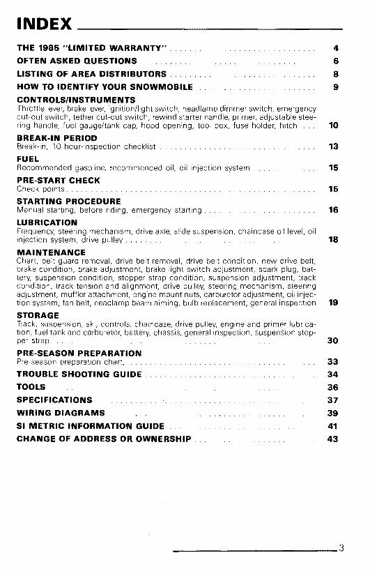
INDEXTHE 1985 "LIMITED WARRANTY" . 4
OFTEN ASKED QUESTIONS 6
LISTING OF AREA DISTRIBUTORS. 8
HOW TO IDENTIFY YOUR SNOWMOBILE 9
CONTROLS/INSTRUMENTSThrottle lever, brake lever, ignition/light switch, headlamp dimmer switch, emergencycut-out switch, tether cut-out switch, rewind starter handle, primer, adjustable stee-ring handle, fuel gauge/tank cap, hood opening, tool box, fuse holder, hitch 10
BREAK-IN PERIODBreak-in, 10 hour-inspection checklist 13
FUELRecommended gasoline, recommended oil, oil injection system. 15
PRE-START CHECKCheck points. 15
STARTING PROCEDUREManual starting, before riding, emergency starting. . 16
LUBRICATIONFrequency, steering mechanism, drive axle, slide suspension, chaincase oil level, oilinjection system, drive pulley. . 18
MAINTENANCEChart, belt guard removal, drive belt removal, drive belt condition, new drive belt,brake condition, brake adjustment, brake light switch adjustment, spark plug, battery, suspension condition, stopper strap condition, suspension adjustment, trackcondition, track tension and alignment, drive pulley, steering mechanism, steeringadjustment, muffler attachment, engine mount nuts, carburetor adjustment, oil injec-tion system, fan belt, headlamp beam aiming, bulb replacement, general inspection 19
STORAGETrack, suspension, ski, controls, chaincase, drive pulley, engine and primer lubrication, fuel tank and carburetor, battery, chassis, general inspection, suspension stop-per strap 30
PRE-SEASON PREPARATIONPre-season preparation chart, 33
TROUBLE SHOOTING GUIDE. 34
TOOLS 36
SPECIFICATIONS. 37
WIRING DIAGRAMS 39
SI METRIC INFORMATION GUIDE 41
CHANGE OF ADDRESS OR OWNERSHIP 43
______________ 3

THE 1985 LIMITED WARRANTV _
1 - PERIODBOMBARDIER® INC. as manufacturer, warrants FROM THE DATE OF FIRSTCONSUMER SALES, every 1985 BOMBARDIER® snowmobile, sold as NEWAND UNUSED, by an authorized BOMBARDIER dealer for a period of:
• 12 consecutive months.
2 - WHAT BOMBARDIER WILL DOBOMBARDIER will repair and/or replace, at its option, components defectivein material and/or workmanship (under normal use and service,) with a genuine BOMBARDIER component without charge for parts or labour, at any authorized BOMBARDIER dealer during said warranty period.
3 - CONDITION TO HAVE WARRANTY WORK PERFORMEDPresent to the servicing dealer, the hard copy of the BOMBARDIER WarrantyRegistration card received by the customer from the selling dealer at time ofpurchase.
4 - WARRANTY TRANSFERThis warranty is transferable to subsequent owner(s) for remainder of warranty period from original date of sale.
5 - EXCLUSIONS - ARE NOT WARRANTED• Normal wear on all items such as, but not limited to:
- drive belts- slider shoes- spark plugs- bulbs- runners on skis
• Replacement parts and/or accessories which are not genuine BOMBARDIERparts and/or accessories.
• Damage resulting from installation of parts other than genuine BOMBARDIER parts.
• Damage caused by failure to provide proper maintenance as detailed in theOperator Manual. The labour, parts and lubricants costs of all maintenanceservices. including tune-ups and adjustments will be charged to the owner.
• Wet cells battery.
• Vehicles designed and/or used for racing purposes.
• All optional accessories installed on the vehicle.(The normal warranty policy for parts and accessories, if any, applies).
• Damage resulting from accident, fire or other casualty, misuse, abuse orneglect.
• Damage resulting from operation of the snowmobile on surfaces other thansnow.
4 _

• Damage resulting from modification to the snowmobile not approved in writing by BOMBARDIER.
• Losses incurred by the snowmobile owner other than parts and labour, suchas, but not limited to, transportation, towing, telephone calls, taxis, or anyother incidental or consequential damages.
6 - BATTERY WARRANTY:• 12 consecutive months. (pro-rated.)
100% warranty coverage will start on the date the snowmobile was purchased and run to the following April 30th. The remainder of the 12 monthsperiod will be pro-rated as follows:- 50% from April 30th to December 1st.- 40% from December 1st to December 31 st.- 30% from January 1st to end of warranty.
7 - EXPRESSED OR IMPLIED WARRANTIESThis warranty gives you specific rights, and you may also have otherlegal rights which may vary from state to state, or province to province.Where applicable this warranty is expressly in lieu of all other expressed or implied warranties of BOMBARDIER, its distributors and the seIling dealer, including any warranty of merchantability of fitness for anyparticular purpose; otherwise the implied warranty is limited to the duration of this warranty. However, some states or provinces do not allowlimitations on how long an implied warranty lasts, so the above limitation may not apply.Neither the distributor, the selling dealer, nor any other person has beenauthorized to make any affirmation, representation or warranty otherthan those contained in this warranty, and if made, such affirmation,representation or warranty shall not be enforceable against BOMBARDIER or any other person.Some states or provinces do not allow the exclusion or limitation of incidental or consequential damages, so the above limitation or exclusionmay not apply.
BOMBARDIER INC. reserves the right to modify its warranty policy atany time, being understood that such modification will not alter the warranty conditions applicable to vehicles sold while the above warrantyis in effect.
8 - CONSUMER ASSISTANCEIf a servicing problem or other difficulty occurs, we suggest the following:
1. Try to resolve the problem at the dealership with the Service Manager 0Owner.
2. If this fails, contact your area distributor listed in the Operator Manual.
3. Then if your grievance still remains unsolved, you may write to us:
Bombardier Inc.Service DepartmentRecreational Products DivisionValcourt, Ouebec, Canada, JOE 2LO
February 1984Bombardier Inc.Valcourt, Ouebec, Canada. JOE 2LO
@*Trademarks of Bombardier Inc._____________........5

OFTEN ASKEDauESTIONS _
0: Why must my snowmobile be registered? After alii do have my original invoiceas proof of when I purchased my snowmobile.
A: Your warranty is valid at any authorized dealer of the product. Your registration is the key element in providing the servicing dealer with the necessarydata to complete warranty claim forms. This information is also used to notifyowners in the event of a safety recall.
0: I bought my snowmobile in O'King County but I snowmobile in WashingtonCounty. Can the dealer in Washington County accept to perform warranty workon my snowmobile?
A: Yes, any authorized dealer in North America can perform warranty repairs,providing the customer warranty registration card is presented.
0: Where can I find information on the lubrication and maintenance of my snowmobile?
A: In this Operator Manual provided with the vehicle at the time of first sale.
0: Will the entire warranty be void or cancelled, if I do not operate or maintainmy new snowmobile exactly as specified in the Operator's Manual?
A: The warranty of the new snowmobile cannot be "Voided" or "Cancelled". However, if a particular failure is caused by operation or maintenanceother than is shown in the Operator Manual, THAT failure may not be coveredunder warranty. This includes service work performed by the customer,especially the critical adjustments to ignition, timing, carburation and oil injection/or oil mixture.
0: Would you give some examples of abnormal use or strain, neglect or abuse?
A: These terms are general and overlap each other in areas. Some specificexamples may include: running the machine out of oil, chain failure causedby a lack oflubrication, operating the machine with a broken or damaged partwhich causes another part to fail, and so on. If you have any specific questions on operation or maintenance, please contact your dealer for advice.
0: What costs are my responsibility during the warranty period?
A: The customer's responsibility includes a/l costs ofnormalmaintenance services, non-warranty repairs, accidents and collision damage, as well as oils,and spark plugs, and incidental or consequential damages costs as explainedin the warranty.
6 _
Q: Are "Genuine" Bombardier replacement parts used in warranty repairs coveredby warranty?
A: Yes. When installed by an authorized dealer, any "genuine" Bombardierpart used in warranty repairs assumes the remaining warranty that exists onthe machine.
Q: If I sell my snowmobile within the warranty period, will the new owner qualifyfor the balance of the warranty?
A: Yes, provided the unit has already been registered with the manufacturer.Note that the change of ownership card in this manual should be completedand sent to Bombardier Inc.
Q: How can I receive the best owner assistance?
A: The satisfaction and goodwill of the owners of Bombardier products areofprimary concern to your dealer and Bombardier Inc. Normally, any problemsthat arise in connection with the sales transaction or the operation of yoursnowmobile will be handled by your Dealers Sales or Service Departments.It is recognized, however, that despite the best intentions ofeveryone concerned, misunderstandings w/JI sometimes occur. If you have a problem that hasnot been handled to your satisfaction through normal channels, we suggestthat you discuss your problem with a member ofdealership management. Frequently, complaints are the result ofa breakdown in communications and canquickly be resolved by a member of the dealership management. If the problem already has been reviewed with the Sales Manager or Service Manager,contact the Dealer himself or the General Manager.
______________7

LISTING OF AREADISTRIBUTORS _
CANADIAN DISTRIBUTORS
BOMBARDIER INC.EASTERN CANADA DISTRIBUTION DIVISIONAtlantic BranchP.O. Box 670Shediac, New Brunswick, EOA 3GO(506) 386-6117Magdalen Island, Nova Scotia, NewBrunswick, Prince Edward Island
Quebec Branch1350 Nobel BoulevardBoucherville, Quebec, J4B 1A1(514) 655-6121Province of Quebec
Ontario Branch230 Bayview DriveBarrie, Ontario, L4N 4Y8(7051 728-8600Province of Ontario
BROOKS EQUIPMENT LIMITED1616 King, Edward StreetP.O. Box 985Winnipeg, Manitoba, R3C 2V8{204) 633-7247British Columbia, .Manitoba, Saskatchewan,Alberta, Yukon
CHARLES R. BELL LIMITEDNewfoundland, LabradorOffices- Riverside Drive
P.O. Box 1050Corner Brook, Newfoundland, A2H 6J3(7091 634-3533
- 81 Kenmount RoadP.O. Box 8127St-John's, Newfoundland, AlB 3Nl(7091 722-6700
HUDSON'S BAY CO. LTD.165 Hymus BlvdPointe-Claire, Quebec, H9R 1G2(5141697-8500North-West Territories, Franklin District &Keewatin
AMERICAN DISTRIBUTORS
BOMBARDIER CORPORATIONAll States (excluding Alaska)
SERVICE OFFICES- East Main Street Road
Malone, New York 12953{518} 483-4411
- 4505 West Superior StreetP.O. Box 6106Duluth, Minnesota 55806(2181628-2881
- P.O. Box 1569Idaho Falls, Idaho, 83401(208) 529-9510
NATIONAL SALES OFFICE- O'Hare Lake Plaza
2350 Devon AvenueSuite 150Des Plaines, Illinois 60018(312) 298-9540
MILLER EQUIPMENT AND RECREATIONALCENTER1049 Whitney RoadAnchorage, Alaska 99501(907) 274-9513Alaska
8 _

HOW TO IDENTIFYYOUR SNOWMOBILE _
The main components of your snowmobile (engine, trackts) and frame) areidentified by different serial numbers. Itmay sometimes become necessary tolocate these numbers for warranty purposes or to trace your snowmobile inthe event of theft.
VEHICLE SERIAL NUMBER
ENGINESERIALNUMBER
O NOTE: We strongly recommend that you take note of all the serial numberson your vehicle and supply them to your insurance company. It will surely
help in the event a snowmobile is stolen.
_____________9

CONTROLS/INSTRUMENTS _
I-~-----r~~
F-+---H-lll-W
K
~~l---~_IC
\U)~--+--H
\...\i--+-G
AJ Throttle Control LeverBJ Brake Control LeverCJ Ignition/Ught SwitchDJ Headlamp Dimmer SwitchEJ Emergency Cut-Out SwitchFJ Tether Cut-Out Switch
A) Throttle LeverLocated on right side of handlebar.When compressed, it controls the engine speed and the engagement of thetransmission. When released, enginespeed returns automatically to idle.
B) Brake LeverLocated on the left side of handlebar.When compressed, the brake is applied.When released, it automatically returnsto its original position. Braking effect isproportionate to the pressure applied onthe lever and to the type of terrain andits snow coverage.
GJ Rewind Starter HandleHJ PrimerIJ Adjustable steering handleJJ FuelgaugehankcapKJ Hood Opening
C) Ignition/Light SwitchThe ligts are automatically ON whenever the engine is running.
Manual starting
OFF
CD_ONKeyoperated, 2 position switch. Tostartengine, first turn key fully clockwise toON position. To stop engine, turn keycounter-clockwise to OFF position.
10· _

Electric starting
OFF
f1:\~ON\..9" START
Key operated, 3 position switch. To startengine, turn key fully clockwise toSTART position and hold. Return key toON position immediately when enginehas started. To stop engine, turn keycounter-clockwise to OFF position.
_ CAUTION: Holding key in START.. position when engine has started
could damage starter mechanism.
D) Headlamp Dimmer Switch
The dimmer switch, located on left sideof handlebar, allows correct selection ofheadlamp beam. To obtain high or lowbeam simply flick switch.
•WA RNING: If the switch hasbeen used in an emergency situa
tion the source of malfunction shouldbe determined and corrected before restarting engine.
F) Tether Cut-Out SwitchAttach tether cord to wrist or other convenient location then snap tether cutout cap over receptacle before startingengine.
Attach towrist
+ON t OFF
~~
E) Emergency Cut-Out SwitchA push pull type switch located on theright side of the handlebar. To stop theengine in an emergency, push the button to the lower off position and simultaneously apply the brakes. To startengine, button must be at the upper ONposition.
Upper positionBefore starting
Lower positionto stop engine
If emergency engine "shut off" is required, completely pull cap from safetyswitch and engine power will be automatically shut' 'off '.
O NOTE: The cap must be installedon the safety switch at all times in
order to operate the vehicle.
•WARNING: If the switch is usedin an emergency situation the
source of malfunction should bedetermined and corrected before restarting engine.
G) Rewind Starter HandleAuto rewind type located on right handside Of vehicle. To engage mechanism,pull handle.
The driver of this vehicle should familiarize himself with the function of thisdevice by using it several times on firstouting. Thereby being mentally prepared for emergency situations requiringits use.
_____________11
H) PrimerA push-pull button. Pull and push button (2-3 times) to activate primer. Theprimer should always be used for coldengine starts. After engine is warm however, it is not necessary to use primerwhen starting.
I) Adjustable Steering Handle- Remove steering cover.
- Loosen the four (4) retaining screws.
- Adjust the handle to the desired po-sition.
+WA RNING: Do not adjust toohigh as the brake lever may con
tact the windshield when turning.
- Lock the steering handle in place bytightening the four (4) retainingscrews to 26 N-m (19 lbt-ft).
- Reinstall steering cover.
J) Fuel Gauge/Tank CapUnscrew fuel tank cap and withdrawdipstick to check fuel level.
+WARNING: Never use a lit matchor open flame to check
fuel lever.
K) Hood OpeningPull down the latches to unlock thehood from the anchor.
O NOTE: Always lift hood gently upuntil stopped by restraining device.
+WARNING: It is dangerous to runan engine with the hood open un
fastened or removed. Personal injurycould result.
Tool BoxLocated under the hood. Togain access,tilt hood. Ideal location for spare rope,first aid kit, etc ...
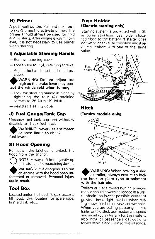
Fuse Holder(Electric starting only)
Starting system is protected with a 30amperes rated fuse. Fuse holder is located close to the battery. If starter doesnot work, check fuse condition and if required replace with one of the samevalue.
Hitch(Tundra models only)
+WARNING: When towing a sledor trailer, always ensure to lock
the hook or plate type attachmentwith the hair pin.
Trailers or sleds towed behind a snowmobile should always be loaded in a wayto obtain the lowest possible center ofgravity. Use a rigid tow bar when pulling a tow sled behind your snowmobile.When you are pulling passengers in atrailer or tow sled, use modernate speedand avoid rough terrain for their safety.also, have all passengers get out of atowed vehicle and walk across all roads.
12 _

BREAK-IN PERIOD _Engine
This Bombardier-Rotax snowmobileenqine. has a critical break-in period requirement before running the vehicle atfull throttle. Engine manufacturerstrongly recommends 10 (0 15 operating hours. Maximum throttle should notexceed 3/4, however, brier full acceleration and speed variations contribute to a good break-in. Continued wideopen throttle accelerations, prolongedcnnsmq speeds, and lugging are detrimental during the break-in period.
O NOTE: For the break-in period only, 450 ml (16 oz) of Bombardier
Snowmobile Injection oil should beadded to the first full fuel tank filling.
This will assure additional protection during the initial engine break-in.
~ CAUTION: Remove and clean.". spark plugs after engine break-in.
Belt- A new drive belt requires a break-in
period of 15-25 km (10-15 miles).
10~HOUR INSPECTIONAs with any precision piece of mechanical equipment, we suggest that afterthe first 10 hours of operation or 30days after the purchase, whichevercomes first, that your vehicle be checked by your dealer. This inspection willgive you the opportunity to discuss theunanswered questions you may haveencountered during the first hours ofoperation. Remember that it is easier toremedy at this time than to allow thesnowmobile to operate until a possiblefailure occurs.
The 10 hour inspection is at the expenseof the vehicle owner.
____________13

10-HOUR INSPECTION CHECKLIST ~Engine timing
Fan belt tension
Spark plug condition: (Remove and clean)
Carburetor adjustment
Oil injection pump adjustment
Battery electrolyte level (electric starting only)
Engine mount nuts
Muffler attachment
Chaincase oil level
Injection system oil level
Brake operation and lining condition
Ski alignment (runners condition)
Steering arm, retorque to 61 N.m (45 Ibf-ft)
Handlebar bolts, retorque to 26 N·m (19 Ibf-ft)
Pulley alignment and drive belt condition
Track condition, tension and alignment
Lubrication (steering, suspension, drive axle)
Electrical wiring (loose connections, stripped wires, damaged insula-tion), tighten all loose bolts, nuts and linkage
Operation of lighting system (HI / LO beam, brake light, etc.), testoperation of emergency cut-out switch and tether switch
We recommend that you have your dealer sign this inspection list.
Date of 10 hour inspection Dealer signature
14 _

FUEL _
Recommended GasolineUse regular leaded or unleaded gasolineavailable from all service stations._ CAUTION: Never experiment with... different fuel or fuel ratios. Never
use naphtha, methanol, gasohol orsimilar products .
•WARNING: Never "top up" thegas tank before placing the vehi
cle in a warm area. At certain temperatures, gasoline will expand and overflow. Always wipe off any gasolinespillage from the snowmobile.
Recommended OilUse "Bombardier Snowmobile InjectionOil" (PIN 496 0133 00 - 1 liter) available from your dealer. This type of oilwill flow at temperatures as low as minus 40°C (-40°F).
It is a blend of specially selected baseoils and additives which provides outstanding lubrication, engine cleanlinessand minimum spark plug fouling.
If "Bombardier Snowmobile InjectionOil" is unavailable, substitute with BLIZZARD oil (PIN 496 0135 OO).
_ CAUTION: Never use outboard... or straight mineral oils.
Oil Injection SystemAlways maintain a sufficient amount ofBombardier Snowmobile injection oil inthe injection oil tank.
_ CAUTION: Check level and refill... every time you refuel.
O NOTE: For the break-in period only, 450 ml (16 oz.) of Bombardier
Snowmobile injection oil should be added to the first full fuel tank filling. Thiswill assure additionnal protection duringthe initial engine break-in.
PRE-START CHECK _
Check Points• ACTIVATE THE THROTTLE CON
TROL LEVER SEVERAL TIMES tocheck that it operates easily andsmoothly. The throttle control levermust return to idle position when released
• Check fuel level.
• Check injection oil level.
• Check that the skis and the track arenot frozen to the ground or snow surface and that steering operates freely.
• Activate the brake control level andmake sure the brake fully applies before the brake control lever touchesthe handlebar grip.
• Verify that the path ahead of the vehicle is clear of bystanders and obstacles.
•WARNING: Only start your snowmobile once all components are
checked and functioning properly.
____________15
STARTINGPROCEDURE _
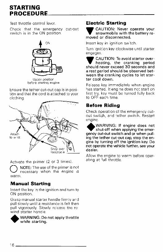
Test throttle control lever.
Check that the emergency cut-outswitch is in the ON position.
+ON
Upper positionbefore starting engine
Ensure the tether cut-out cap is in position and that the cord is attached to yourclothing.
~Snap overreceptacle _
Activate the primer (2 or 3 times).
O NOTE: The use of the primer is notnecessary when the engine is
warm.
Manual StartingInsert the key in the ignition and turn toON position.
Grasp manual starter handle firmly andpull slowly until a resistance is felt thenpull vigorously. Slowly release the rewind starter handle.
+ WARNING: Do not apply throttlewhile starting.
Electric Starting_ CAUTION: Never operate your". snowmobile with the battery re
moved or disconnected.
Insert key in ignition switch.
Turn ignition key clockwise until starterengages.
_ CAUTION: To avoid starter over". heating, the cranking period
should never exceed 30 seconds anda rest period should be observed between the cranking cycles to let starter cool down.
Release key immediately when enginehas started. It engine does not start onfirst try, key must be turned fully backto OFF each time.
Before RidingCheck operation of the emergency cutout switch, and tether switch. Restartengine.
+WA RNING: If engine does notshut-off when applying the emer
gency cut-out switch and or when pulling the tether cut-out cap, stop the engine by turning off the ignition key. Donot operate the vehicle further, see yourdealer.
Allow the engine to warm before operating at full throttle.
16 _

Emergency StartingShould the rewind starter rope fray andbreak, the engine can be started with anemergency starter rope.
•WARNING: Do not start the vehicle by the drive pulley unless it
is a true emergency situation, have thevehicle repaired as soon as possible.
Remove the belt guard from vehicle.(See "Maintenance section").
Assemble the handle to the emergencystarting rope and wind the rope tightlyaround the drive pulley
•WARNING: Do not wind startingrope around your hand. Hold
rope by the handle only.
Start as per manual starting procedure.
•WARNING: When starting the vehicle in an emergency situation by
the drive pulley, do not reinstall the beltguard.
_____________17

LUBRICATION _
Oil spring coupler bolts, ball joints andsteering column bushings.
".~~~-j8
~-+-'==-7>/
Drive AxleLubricate at grease fitting using lowtemperature grease.
FrequencyRoutine maintenance is necessary for allmechanized products, and the snowmobile is no exception. A weekly vehicle inspection contributes to the lifespan of the snowmobile as well asretains safe and dependable operation.
•WARNING: Only perform suchprocedures as detailed in this
manual. It is recommended that dealer assistance be periodically obtainedon other components/systems notcovered in this manual. Unless otherwise specified, engine should be turned OFF for all lubrication andmaintenance procedures.
It is recommended that the steering system and suspension be lubricated monthly or every 40 hours of operation. If thevehicle is operated in wet snow or insevere conditions these items should belubricated more frequently.
Steering Mechanism
•WARNING: Do not lubricate throttle and/or brake cables and hous
ings.
Lubricate the ski legs at grease fittingsuntil new grease appears at joints. Coatspring slider cushion with grease.
_ CAUTION: When lubricating the" drive axle bearing, do not apply
excessive grease as the seal will bepushed out of its housing.
18 _

Check seal position with finger.
Slide SuspensionCitation LS & LSE
Chaincase Oil Level
Check the oil by removing the chaincaseplug.
Also lubricate front & rear arms atgrease fittings.
oil level
Drive PulleyDesigned with karlon bushings, no lubrication is required.
_ CAUTION: Check level and refill.". every time you refuel.
Oil Injection SystemAlways maintain a sufficient amount ofBombardier Snowmobile Injection Oil inthe injection oil tank.
The oil should be level with the bottomof the oil level orifice.
O NOTE: The chaincase oil capacityis approximately 200 ml (7 oz.).
7o
This suspension type does not requireany lubrication.
Tundra & Tundra LTLubricate idler wheels at grease fittingsuntil grease appears at joints. Use lowtemperature grease only
_____________19

MAINTENANCE _The following Maintenance Chart indicates regular servicing schedules to beperformed by you or your servicing dealer. If these services are performed assuggested, your snowmobile will giveyou many years of low-cost use.
•WARNING: Only perform suchprocedures as detailed in this
manual. It is recommended that dealer assistance be periodically obtainedon other components/systems not covered in this manual. Unless otherwise specified, engine should beturned OFF for all lubrication andmaintenance procedures.
E E0 0 oJ)
MAINTENANCE ~0 co OlII) OJ- ~ ~ E o,
CHART >-~E >CE OJ C E 832~~ N~~ Q,)?;OO:E m o Cwo owoS $s~"'" ~~o 8o~~
(I)
0"1 oro a:
Drive belt condition • 22
Brake condition • 22
Brake adjustment • 22
Spark plug • 23
Battery (electric starting) • 23
Suspension condition • 24
Suspension stopper strap condition • 24
Suspension adjustment (as required) 24
Track condition • 25
Track tension and alignment • 25
Drive pulley • 26
Steering mechanism • 26
Steering adjustment • 26
Muffler attachment • 27
Engine mount nuts • 27
Carburator adjustment • 27
Injection oil filter condition • 28
Oil injection pump adjustment • 28
Fan belt • 28
Headlamp beam aiming • 28
General inspection • 30
O NO:rE: The ten hour inspection is a very important part of proper service andmaintenance.
20 _

Belt Guard Removal
•WARNING: Belt guard shouldalways be in place when engine
is running.
A. Raise the hood and pull both retaining pins out.
B. Pull the guard out of the center retaining bolt.
C. Remove the guard.
10 Pull hair pin
I3 0 Raise driven pulley
support.
4. Slip the belt over the top edge of thesliding half.
Driven pulley10 Twist clockwise
2° Push
3. Open the driven pulley by twistingand pushing the sliding half. Hold infully open position.
Drive Belt RemovalInstallation1. Remove the belt guard.
2. Unlock and raise driven pulleysupport.
_____________ 21

5 Slip the belt out from the drive pulley and remove completely fromvehicle.
Drive pulley
To install the drive belt, reverse the procedure.
Drive Belt ConditionInspect belt for cracks, fraying or abnormal wear (uneven wear, wear on oneside, missing cogs, cracked fabric). Ifabnormal wear is noted, probable causecould be pulley misalignment, excessiveR.P.M. with frozen track, fast startswithout warm-up period, burred sheave,oil on belt or distorted spare belt. Contact your dealer.
Check the drive belt width. If less than30 mm (1 3/16 in), replace the drive belt.
New Drive BeltWhen installing a new drive belt, breakin period of 25 km (15 miles) is stronglyrecommended.
O NOTE: Always store a spare beltin a manner to allow its natural
shape to be maintained.
Brake ConditionThe brake mechanism on your snowmobile is an essential safety device.Keep this mechanism in proper workingcondition. Above all, do not operateyour snowmobile without an effectivebrake system.
•WARNING: Brake pads must bereplaced as soon as only 1 mm
(1132") of the fixed lining is still projected out of caliper. Replacementmust be performed by an authorizeddealer.
Minimum projectionof fixed pad: 1 mm (1/32")
Brake AdjustmentThe brake mechanism is a self-adjustingtype. If a quicker brake response is desired, strongly pull the brake lever several times, this will actuate the selfadjusting mechanism.
After the adjustment, brake should apply fully when lever is approximatively13 mm (1/2") from handlebar grip. Ifnot, do not tamper with the brake, contact your servicing dealer.
13 mm (112")approx.
22 _

_ CAUTION: If spark plug condl.". tion is not ideal, contact your au
thorized dealer.
Check spark plug gap using a wire feeler gauge.
Reinstall plug and connect wire.
Fouled(black)
Normal(brownish)
Overheated(light grey)
Spark Plug
Disconnect the spark plug wire andremove the spark plug.
Check the condition of the plug.
• A brownish tip reflects ideal conditions.(Carburetor adjustments, spark plugheat range, etc, are correct.)
• A black insulator tip indicates foulingcaused by: carburetor idle speed mixture and/or high speed mixture toorich, incorrect fuel mixture ratio, wrongtype of spark plug (heat range), orexcessive idling.
• A light grey insulator tip indicates alean mixture caused by: carburetorhigh speed mixture adjusted too lean,wrong spark plug heat range, incorrect fuel mixture ratio, or a leakingseal or gasket.
Pull outward to lit
Brake Light SwitchAdjustmentTo check operation:
Pull the brake lever to hold the pads onthe disc. Check that a light resistanceis felt while rotating the driven pulley.This is the position where the switchshould have lit the brake light.
To adjust:
- Loosen the brake switch lock nut whilerestraining the other one.
- By turning adjusting nut, pull outwardthe switch to turn the light on or pushinward to turn it off.
- Tighten the lock nut while restrainingthe other one. Recheck brake light operation.
Adjusting nut
Battery(Electric starting only)Check electrolyte level weekly. Electrolyte level must be at upper level line onbattery casing.
____________23

Ski/track transfer weight
Stopper Strap ConditionInspect strap for wear and cracks, boltand nut for tightness. If loose inspectholes for deformation. Replace as required. Torque nut to 9 N-m (7 lbt-ft).
Suspension Adjustment
Citation LS 8r. LSEThese models do not have any adjustment on the suspension.
Tundra 8r. Tundra LTThe suspension is adjustable, the frontadjustment for surface condition, therear for driver's weight.
Suspension ConditionVisually inspect all suspension components including slider shoes, springs,wheels, etc...
O NOTE: During normal driving,snow will act as a lubricant and
coolant for the slider shoes. Extensiveriding on ice or sanded snow, will createexcessive heat build-up and cause premature slider shoe wear.
When the front adjuster blocks are atthe lowest elevation more weight is distributed on the skis.
O NOTE: always keep battery fUllycharged. (To charge, refer to
"Battery" in "Storage" section l.
If necessary add distilled water. Batteryconnections must also be free of corrosion. If cleaning is necessary removecorrosion using a stiff brush then cleanwith a solution of baking soda andwater. Rinse and dry well._ CAUTION: Do not allow cleaning." solution to enter battery. It
will destroy the chemical properties ofthe electrolyte.
After reconnecting battery, coat batteryterminals and connectors with petroleum jelly to prevent corrosion. Checkthat battery is well secured and that battery vent tube is not kinked or blocked.
Minimum level
Maximum level--l-l-lll-ll""
•WARNING: Vent tube must befree and open. If not, it will re
strict ventilation and create a gas accumulation that could result in an explosion. Avoid skin contact withelectrolyte.
_ CAUTION: Prior to charging the." battery, always remove it from
the vehicle to prevent electrolytespillage.
24 _
Tundra &Tundra LT
only.Loosen
13 rnrn (112")
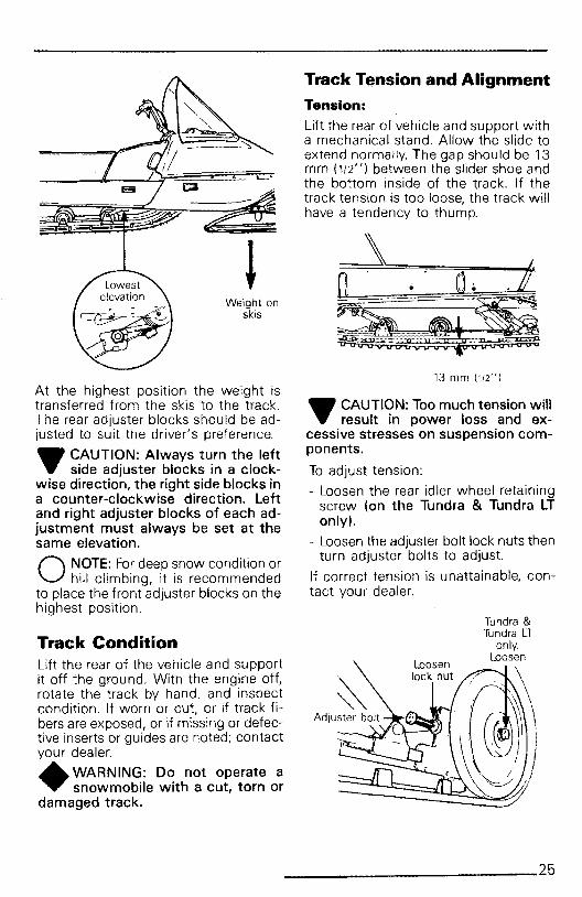
.. CAUTION: Too much tension will". result in power loss and ex
cessive stresses on suspension components.
To adjust tension:
- Loosen the rear idler wheel retainingscrew (on the Tundra & Tundra LTonly).
- Loosen the adjuster bolt lock nuts thenturn adjuster bolts to adjust.
If correct tension is unattainable, contact your dealer.
Track Tension and AlignmentTension:
Lift the rear of vehicle and support witha mechanical stand. Allow the slide toextend normally. The gap should be 13mm (1/2") between the slider shoe andthe bottom inside of the track. If thetrack tension is too loose, the track willhave a tendency to thump.
I ~.j0 o~
Weight on ~skis
Track ConditionLift the rear of the vehicle and supportit off the ground. With the engine off,rotate the track by hand, and inspectcondition. If worn or cut, or if track fibers are exposed, or if missing or defective inserts or guides are noted; contactyour dealer.
•WARNING: Do not operate asnowmobile with a cut, torn or
damaged track.
At the highest position the weight istransferred from the skis to the track.The rear adjuster blocks should be adjusted to suit the driver's preference.
_ CAUTION: Always turn the left". side adjuster blocks in a clock
wise direction, the right side blocks ina counter-clockwise direction. Leftand right adjuster blocks of each adjustment must always be set at thesame elevation.
O NOTE: For deep snow condition orhill climbing, it is recommended
to place the front adjuster blocks on thehighest position.
____________25

Tighten lock nuts and recheck thealignment.
61 N.m (45 Ibf.ft)
Drive PulleyDesigned with karlon bushings, no lubrication is required. Should be inspected annually by an authorized dealer.
Steering MechanismInspect the steering mechanism fortightness of components (steering arms,tie rods, ball joints, spring coupler bolts,etc.I. If necessary, replace or retighten.
Torque steering arm bolts as shown:
O NOTE: Track tension and alignment are inter-related. Do not ad
just one without the other.
Alignment
Start the engine and accelerate slightlyso that track turns slowly. Check thatthe track is well centered; equal distance on both sides between edges oftrack guides and slider shoes.
J
•WARNING: Beforecheckingtrackalignment, ensure that the track
is free of all particles which could bethrown out while track is rotating.Keep hands, tools, feet and clothingclear of track. Ensure no-one is standing in close proximity to the vehicle.
To correct, stop the engine: Loosen thelock nuts and tighten the adjuster bolton side where the slider shoe is the farthest to the track insert guides
/GU ideS~Slider
/shoes <,
~~ghtenon this side.
Check the condition of the skis and theski runners. Replace if more than halfworn.
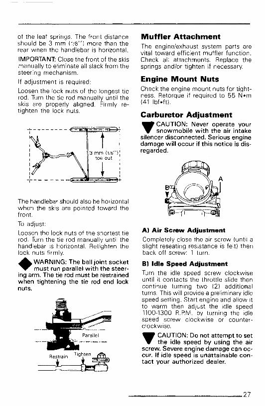
Steering AdjustmentSkis should have a toe out of 3 mm(1/8"). To check, measure the distancebetween each ski at the front and rear
26 _
Restra_in_T_ig-i:hten~
====! ~
B) Idle Speed AdjustmentTurn the idle speed screw clockwiseuntil it contacts the throttle slide thencontinue turning two (2) additionalturns. This will provide a preliminary idlespeed setting. Start engine and allow itto warm then adjust the idle speed1100-1300 R.PM. by turning the idlespeed screw clockwise or counterclockwise.
_ CAUTION: Do not attempt to set.. the idle speed by using the air
screw. Severe engine damage can occur. If idle speed is unattainable contact your authorized dealer.
A) Air Screw Adjustment
Completely close the air screw (until aslight reseating resistance is felt) thenback off screw: 1 turn.
Muffler AttachmentThe engine/exhaust system parts arevital toward efficient muffler function.Check all attachments. Replace thesprings and/or tighten if necessary.
Engine Mount NutsCheck the engine mount nuts for tightness. Retorque if required to 55 N·m(41 lbt-ft).
Carburetor Adjustment_ CAUTION: Never operate your.. snowmobile with the air intake
silencer disconnected. Serious enginedamage will occur if this notice is disregarded.
,,
t i3 mm (118"):
toe out I
~ i~~~~3+
-~ - - - - - - - - €~~~~'fIIIIII
IIII
The handlebar should also be horizontalwhen the skis are pointed toward thefront.
To adjust:
Loosen the lock nuts of the shortest tierod. Turn the tie rod manually until thehandlebar is horizontal. Retighten thelock nuts firmly.
•WARNING: The ball joint socketmust run parallel with the steer
ing arm. The tie rod must be restrainedwhen tightening the tie rod end locknuts.
of the leaf springs. The front distanceshould be 3 mm (118") more than therear when the handlebar is horizontal.
IMPORTANT: Close the front of the skismanually to eliminate all slack from thesteering mechanism.
If adjustment is required:
Loosen the lock nuts of the longest tierod. Turn the tie rod manually until theskis are properly aligned. Firmly retighten the lock nuts.
____________27

Oil Injection System
Injection Oil Filter ConditionInspect oil filter at least once a month.Insure that filter is not obstructed byforeign particles; if so, see your dealer.
~ CAUTION: An obstructed injec.". tion oil filter will cause oil starva
tion resulting in serious enginedamage.
O NOTE: After a storage period, it isimportant that your dealer re
places the injection oil filter and that heverifies the oil flow of the injectionpump.
Injection Pump AdjustmentProper oil injection pump adjustment isvery important Any delay in the opening of the pump can result in serious engine damage.
To check adjustment: eliminate thethrottle cable free-play by pressing thethrottle leveruntil a light resistance is feltthen hold in place. The aligning markson the pump casting and lever mustalign perfectly. If not, contact yourdealer.
Injection pump should be adjusted byyour dealer.
Marks must align
Fan BeltInspect belt for cracks, uneven wear,etc. Check fan belt tension, 10 mm(318") should exist when deflection iscorrect
If belt seems damaged or if tension isincorrect, contact your dealerimmediately.
•WARNING: If fan protector is removed, always reinstall after
servicing.
Headlamp Beam AimingThe angle of the headlamp beam hasbeen pre-adjusted prior to delivery.Should you wish re-adjustment, placethe vehicle on a flat surface 7.6 m (25')from a wall or screen.
TOP VIEW
SIDE VIEW Ground
28 _
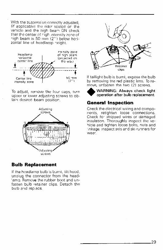
'0!ith the suspension correctly adjusted,(If applicable) the rider seated on thevehicle and the high beam ON checkthat the center of high intensity zone ofhigh beam is 50 mm (2") below horizontal line of headlamp height.
Center lineintensity zone
To adjust, remove the four caps, turnupper or lower adjusting screws to obtain desired beam position.
Adjustingscrews
Bulb Replacement
If the headlamp bulb is burnt, tilt hood,unplug the connector from the headlamp. Remove the rubber boot and unfasten bulb retainer clips. Detach thebulb and replace
If taillight bulb is burnt. expose the bulbby removing the red plastic lens. To remove, unfasten the two (2) screws.
•WARNING: Always check lightoperation after bulb replacement.
General InspectionCheck the electrical wiring and components, retighten loose connections.Check for stripped wires or damagedinsulation. Thoroughly inspect the vehicle and tighten loose bolts, nuts andlinkage. Inspect skis and ski runners forwear.
____________29

STORAGE _It is during summer, or when a vehicleis not in use for any length of time thatproper storage is a necessity. Storage ofthe snowmobile during long period ofinactivity consists of checking andreplacing missing, broken or worn parts,proper lubrication and treatment toinsure that parts do not become rusted;cleaning items such as carbu~etor of 011
mixtures, to prevent gum varnish formation within the carburetor; and In general, preparing the vehicle so that whenthe time comes to use the snowmobileagain it will be in top condition .
•WARNING: Only perform suchprocedures as detailed in this
manual. It is recommended that dealerassistance be periodically obtained onother components/systems not coveredin this manual. Unless otherwise specified, engine should be turned OFF forall lubrication and maintenance procedures.
TrackInspect the track for wear, cuts, missing track guides and broken rods. Makeany necessary replacement
•WARNING: Do not operate asnowmobile with a cut, torn or
damage track.
Lift the rear of vehicle until track is clearof the ground then support with a braceor trestle, The snowmobile should be stored in such a way that the track does notstay in contact with the cement floor orbare ground.
O NOTE: The track should be rotated periodically, (every 40 days).
Do not release track tension
_ CAUTION: To prevent track dam" age temperature in the storage
area mu~t not exceed 38°C (100°F).
SuspensionRemove any dirt or rust Grease idlerwheels at grease fittings. (If applica~le).Wipe off surplus, Replace worn slidershoes.
SkisWash or brush all dirt or rust accumulation from the skis and springs.Grease the ski legs at the grease fittings.Check the condition of the skis, ski runners and leaf springs. Replace if weakor worn more than half.
ControlsLubricate the steering mechanism. Inspect all components for tightness,(spring coupler bolts, steering arm locking bolts, tie rods, ball joints, etc.) Tiqhten if necessary. Oil metal moving JOintsof the brake mechanism.
•WARNING: Do not lubricate thethrottle and/or brake cables and
housings. Avoid getting oil on the brakepads.
Coat all electrical connections andswitches with a greaselessmetal protector. If unavailable, use petroleum jelly.
ChaincaseDrain the chaincase and refill to properlevel, using fresh chaincase oil (PIN 4138019 00), To drain, remove the chaincase cover,
Drive PulleyThe drive pulley should be inspected byan authorized dealer.
Engine and Primer LubricationEngine internal parts must be lubricatedto protect them from possible ~ust formation during the storage period.
30 _

To perform the storage procedures (engine and primer valve) proceed asfollows:
1. Lift the rear of the vehicle and sup-port it off the ground.
+ WARNING: Ensure the track isfree of ails particles which could
be thrown out while it is rotating.Keep hands, tools, feet and clothingclear of track. Ensure no-one is standing in close proximity to the vehicle.
2. Start the engine and allow it to runat idle speed until the engine reachesits operational temperature.
3. Stop the engine.
4. Disconnect the inlet primer hosefrom the primer valve.
Inlet [Obliquehose coupling)
~C't
Outlet (Straighthose coupling I
5. Plug inlet primer hose to preventgasoline from draining.
6. Using an appropriate hose, connectone end of the hose to the inlet ofthe primer valve and place the otherend in a Bombardier Snowmobile Injection Oil container
7. Activate the primer in order to fill itwith oil.
8. Restart engine and run at idle.
9. Using the primer valve, inject oil until the engine dies or until a sufficientquantity of oil has entered the engine (approximately 25 completestrokes of the primed.
10. The engine stopped, remove thespark plug and pour approximately85 ml (3 fl. oz. lrnp.) of oil into thecylinder.
11. Crank the engine to allow the crankshaft to turn 2 or 3 revolutions.
12. Reinstall the spark plug and the inletprimer hose.
Do not run engine during storage period.
Fuel Tank and CarburetorRemove the cap then using a syphon,remove the gasoline from tank.
+WARNING: Gasoline is flammable and explosive under certain
conditions. Always manipulate in awell ventilated area. Do not smoke orallow open flames or sparks in the vicinity.
Carburetor must be dried out completely to prevent gum formation during thestorage period.
Once the fuel tank is emptied, removethe float chamber drain plug from carburetor. Drain carburetor.
Reinstall plug.
Check all fuel lines, replace if necessary.
Battery1. Disconnect the battery cables and
remove the battery retainer cover.
~ CAUTION: Be careful not to... ground positive terminal with
_____________31

O NOTE: To prevent battery from discharging, store it on a wooden
shelf away from moisture. A stored battery must be recharged at least every 40days.
General InspectionCheck the electrical wiring and components, retighten loose connections.Check for stripped wires or damaged insulation.
Thoroughly inspect the vehicle andtighten loose bolts, nuts and linkage.
O NOTE: Leave the drive belt off thepulleys for the entire storage pe
riod.
Suspension Stopper StrapReplace annually and/or as conditiondictates. Torque nut to 9 N-m (7 lbt-ft)
ChassisClean the vehicle thoroughly, removingall dirt and grease accumulation.
_ CAUTION: Plastic alloy compo". nents such as fuel tank, wind
shield, controls, etc., can be cleaned/r--~ using mild detergents or isopropyl al
cohol. Do not use strong soaps, degreasing solvents, abrasive cleaners,paint thinners, etc.
Inspect the hood and repair any damage. Clean the frame.
Touch up all metal spots where painthas been scratched off. Spray all baremetal parts with metal protector. Waxthe hood and the painted portion of theframe for better protection.
O NOTE: Apply wax on glossy finishonly. Protect the vehicle with a
cover to prevent dust accumulationduring storage.
_ CAUTION: If for some reason the". snowmobile has to be stored out
side it is necessary to cover it with anopaque tarpaulin. This caution willprevent the sun rays and the grimefrom affecting the plastic componentsand the vehicle finish.
the chassis. Always disconnect blacknegative cable first.
2 Remove the battery vent tube fromthe vent hole.
3 Lift out the battery.
4. Clean outside surface of battery withsolution of baking soda and water.Remove all deposits from posts thenrinse with clear tap water.
_ CAUTION: Do not allow cleaning". solution to enter battery in
terior since it will destroy the electrolyte.
5. Check electrolyte level. Refill if necessary with distilled water. Fullycharge battery at a maximum rate of2.0 amps.
•WARNING: Gases given off by abattery being charged are high
ly explosive. Always charge in a wellventilated area. Keep battery awayfrom cigarettes or open flames. Avoidskin contact with electrolyte.
6. Coat electrical connections andswitches with a greaseless metalprojector, if unavailable, use petroleum jelly.
7. Store unit in a cool, dry place.
_ CAUTION: Prior to charging the". battery, always remove it from
the vehicle to prevent electrolytespillage.
32 _

PRE-SEASONPREPARATION _
To simplify the pre-season preparationwe have drawn up a small chart. Thechart indicates servicing points to beperformed by you and your servicingdealer. If these services are performedas suggested, your vehicle will give youmany hours of fun and low cost use.
IMPORTANT: Observe all Warningsand Cautions mentioned throughoutthis manual which are pertinent to theitem being checked. When componentconditions seem less than satisfactory,replace with genuine Bombardier partsor suitable equivalents.
TO BE PERFORMED BY DEALER •PRE-SEASONPREPARATION CHART TO BE PERFORMED BY OWNER 0
Change spark plug 0
Check chaincase oil level 0
Replace fuel filter (located inside fuel tank) 0
Check track tension and alignment 0
Lubricate suspension 0
Inspect drive belt and install 0
Check throttle cable for damage and free operation 0
Check steering alignment and ski runner condition 0
Inspect seals for possible cuts or leaks 0
Check electrical wiring (broken wire, damaged insulation) 0
Reinstall battery (electric starting model) 0
Inspect condition of starting rope 0
Check tightness of all bolts, nuts and linkage 0
Refill gas tank 0
Replace injection oil filter •Refill injection oil tank •Inspect brake condition and operation •Set engine timing •Check pulleys, verify components and clean •Adjust carburetor •Adjust oil injection pump •Check fan belt condition and adjust tension •
O *NOTE: Before installing new spark plug, it is suggested to burn the excessstorage oil by starting the engine, using the old spark plug.
~ CAUTION: Only perform this procedure in a well ventilated area.
_____________33

TROUBLE SHOOTINGGUIDE _
O NOTE: The possible causes have been listed in an order of frequency. Therefore, items should be checked out in the same order as mentioned in the
trouble shooting guide.
SYMPTOMS POSSIBLE CAUSES WHAT TO DO
Engine turns over but 1. No fuel to the engine Check the tank level. Check for possible cloggingfails to start or starts of fuel line, item 4.with difficulty
2. Flooded engine Remove wet spark plugs, turn ignition to OFFand crank engine several times. Install cleandry spark plugs. Start engine following usualstarting procedure. If engina continues to flood,see your dealer.
3. Spark plug/ignition Check for fouled ordefective spark plug. Ois-connect spark plug wire, unscrew plug and re-move from cylinder head. Reconnect wire andground exposed plug on engine cowl, beingcareful to hold awey from sperk plug hole.Follow engine starting procedure and checkfor spark. If no sparks appear, replace sparkplug_ If trouble persists, contact your dealer.
4. Clogged fuel line (water or Remove and clean the fuel filter. Change filterdirt) cartridge if necessary. Check condition and
connections of fuel lines. Check the cleanlinessof fuel tank.
5. Carburetor Contact your dealer for repair.
6. Too much oil in fuel Contact your dealer.
7. Engine timing Engine timing may be incorrect or out of ad-justment. Contact your dealer.
a. Engine compression Running with a lean fuel mixture may produceexcessive engine wear resulting in poor enginecompression. If this occurs, contact yourdealer at once.
Engine will not turn 1. Seized engine In the case of a seized engine contact yourmanually dealer.
34 _

SYMPTOMS POSSIBLE CAUSES WHAT TO DO
Engine lacks accelera- 1. Fouled or defective spark Check item 3 of "Engine turns over but failstion or power plug to start or starts with difficulty"
2. Clogged fuel line (water or Check fuel line condition. ISee item 4 of "En-dirt) gine turns over but fails to start orstarts with
difficulty"!.
3. Carburetors Contact your dealer.
4. Ignition First check item 3 of "Engine turns over butfails to start or starts with difficulty". If theignition system still seems faulty, contact yourdealer.
5_ Engine If unable to locate specific symptoms, contactyour dealer.
Engine continually 1. Faulty spark plug Check item 3 of "Engine turns over but fails tobackfires start or starts with difficulty".
2. Overheating Carburetor set too lean. Contact your dealer.
3. Enginetiming incorrectly set Contact your dealer.
Snowmobile cannot 1. Drive Belt Check for damaged or worn drive helt. Re·reach full speed place if necessary.
2. Incorrect track adjustment Check track tension and alignment. Readjustto specifications. ISee Maintenance Section!.
3_ Engine Check item 1 to 5 of "Engine lacks accelera-tion or power.".
4. Pulley misaligned Contact your dealer.
_____________35

TOOLS _As standard equipment each new snowmobile is supplied with basic tools suchas screwdriver, wrenches, emergencystarter rope, etc ...
Standard Tools
A
~-22rDc:=== )
0 HB E
C 0I' G
I ,''Q,:U
A. Screwdriver
B. Socket 21/26 mm
C. Socket 10/13 mm
D. Socket handle
E. Fork wrench 10113 mm
F. Starter rope
G. Emergency starter rope handle
H. Suspension key (Tundra models only)
36 _

SPECIFICATIONS _
CITATION LS TUNDRA TUNDRA LT& LS ELECTRIC
ENGINEType 253No. of cylinders 1Bore 72.0 mm (2.835")Stroke 61.0 mm (2.402")Displacement 248.4 cm 3 (15.16 in3 )Compression ratio 6.25 : 1(effective)Maximum R.P.M 7500Carburetor type VM 34-319Carburetor adjustment:
-air screw 1 turn-idle speed 1100 - 1300 R.P.M.
Fan belt deflection 10 mm (3/8")Torque:-engine head cylinder nuts M8: 21 N·m (15 lbf-It)-crankcase screws M6: 9 N·m (7 lbf-ft)-magneto ring nut 85 N·m (63 lbt-ft)-fan nut 55 N'm (41 lbf·ft)-crankcase engine support 21 N.m (15 lbf-ft)
nuts or screws- electrical starter bolts M5: 3.3 N·m (29 lbf-In)
CHASSISOverall length 242 cm (95.3") 272 cm (107.1") 287 cm (113")Overall width 84.5 cm (33.3") 84.5 cm (33.3") 84.5 cm (33.3")Overall height 91.5 cm (36") 111 cm (43.7") 1 11 cm (43.7")Ski stance (center to 72.5 cm (28.5") 72.5 cm (28.5") 72.5 cm (28.5 ")center)Ski alignment (toe out) 3 mm (1/8") 3 mm (1/8") 3 mm (1/8")Torque:-steering arm/ski leg bolt 61 N.m (45 lbf-ft] 61 N·m (45 IbMt) 61 N-m (45 lbf-ft]-steering column! 26 N·m (19 Ibf·ft) 26 N.m (19 IbMt) 26 N·m (19 Ibf·ft)
handlebarWeight 133.8 kg (295 Ib) 148.8 kg (328 Ib) 162.4 kg (358 Ib)
manual, 150 kg(324 Ib) electric
Bearing area 4748 em- 6600 cm 2 7581 in2
(736 in2) (1023 in2) (11 75 in2)
Ground pressure 2.81 kPa 3.16 kPa 2.14 kPa(.401 Iblin 2) (.440Iblin2) (.30 Ib/in2)
_____________37

CITATION LS TUNDRA TUNDRA LT& LS ELECTRIC
POWER TRAINTrack:-width 38.1 cm (15") 38.1 cm (15") 38.1 cm (15")-length 260 cm (102") 315 cm (124") 353 cm (139")-tension 13 mm (112") gap between slider shoe and bottom inside of track-alignment Equal distance between edge of track guides and slider shoesStandard gear ratio 15/27 12/27 12/27Drive belt:-number 414 523400-max. width 33.3 mm (1 5/16")-min. width 30 mm (1 3/16")Chaincase oil 200 ml (7 OZ)
ELECTRICALLighting system (output) 160 WBulb:-headlamp 60/60 W-tail/stop 5/21 WFuse:-starter solenoi'd 30 ASpark plug-type NGK BR9ES-gap 0.4 mm (.016")Ignition timing:-timing mark (B.T.D.C.) 2.31 mm (.091") (20 0
)
-stroboscopic timing 6000 R.P.M.
FUELGas type regular leaded or unleadedFuel tank capacity
-SI 26 L-Imp. 5.7 Gal-U.S. 6.9 Gal
Injection oilType Bombardier oil injection oil
-SI 1.5 L-Imp. 5302-U.S. 51 oz
BRAKEType Disc self-adjustingLining minimum thickness when only 1 mm (1/32") of fixed pad is projected out of caliperControl lever adjustment 13 mm (l/Z") minimum distance from handlebar grip when fully
apply
Bombardier Inc. reserves the right to make changes in design and specifications andlor to make additions to, or improvements in its product without imposing any obligation upon itself to install themon its products previously manufactured.
38 _

e"'H'G~»C¥CutOuTS.....ITC'"
HTttElI:ClITOlJfSWnCH
FlOllL RIlYl
11K Ill;
RDIIL
"
COLOUR CODE
wco
0) LIGHTING COIL
@ AMPLIFIERo GENERATOR COIL
o HEADLAMP (qO/60 WI
® LIGHT (5 Wl
® REAR LAMP (5-21 Wl
o VOLTAGE REGULATOR@ IGNITION COIL
Re"R LlGHT SWITCH18FlilKEI
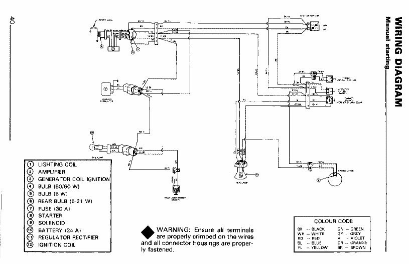
•WARNING: Ensure all terminalsare properly crimped on the wires
and all connector housings are properly fastened.
BK - BLACKWH - WHITERD - REDBL - BLUEYL - YELLOW
GN - GREENGY - GREYVI - VIOLETOR - ORANGESR - BROWN
.J::>. s ~0 rSI>AAJ;PlUG 8IC.,Yt
,"' m(1 " :::l -:DniDI(C
",,< !. -III 2.. C)m::l:j' 0
t = -iI ~rET~€R C)CuT·OUT SWITCH
oMe"I«,iHICY :DCuT.OUT
~SWlTC/J
VOLrAG~ DIMI\oIERfI~GUlATOR " 'iWl'rCH 3:(lV'.!1
rOlIG-H BfIlM.... OW BfAMI,
GN - GREENGY - GREYVI - VIOLETOR - ORANGEBR - BROWN
BK - BLACKWH - WHITERD - REDBL - BLUEYL - YELLOW
COLOUR CODE
flEI\.RLIGI1TSWITCl"IBI'IAKEI
•WARNING: Ensure all terminalsare properly crimped on the wires
and all connector housings are properly fastened.
LIGHTING COIL
AMPLIFIERGENERATOR COIL IGNITION
BULB 160/60 WI
BULB 15 WlREAR BULB 15-21 WI
FUSE (30 AlSTARTER
SOLENOIDBATTERY (24 A)REGULATOR RECTIFIER
IGNITION COIL

51* INFORMATIONGUIDE-----------------
BASE UNITS
DESCRIPTION UNIT SYMBOL
length meter mmass kilogram kg
liquid liter L
temperature celsius DCpressure kilopascal kPa
torque Newton meter N·mspeed kilometer per hour km/h
PREFIXES
PREFIX SYMBOL MEANING VALUE
kilo k one thousand 1,000centi c one hundredth of a 0.01
rnilli m one thousandth of a 0.001
*THE INTERNATIONAL SYSTEM OF UNITS (SYSTEME INTERNATIONAl) ABRE
VIATES "SI" IN ALL LANGUAGES.
_____________41

NOTES _
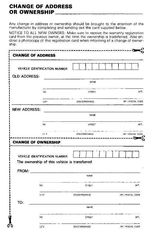
CHANGE OF ADDRESSOR OWNERSHIP _
Any change in address or ownership should be brought to the attention of themanufacturer by completing and sending out the card supplied below.
NOTICE TO ALL NEW OWNERS: Make sure to receive the warranty registrationcard from the previous owner, at the time the ownership is tradsferred. Also enclose a photocopy of this registration card when informing of a change of ownership.
-----------------------------------------------------~CHANGE OF ADDRESS
VEHICLE IDENTIFICATION NUMBER
OLD ADDRESS:NAME
NO STREET APT.
CITY STATEIPROVINCE ZIP / POSTAL CODE
NEW ADDRESS:NAME
APT.STREETNO•••II
: CITY STATE/PROVINCE ZIP / POSTAL CODE
1 -----------------------------------------------~CHANGE OF OWNERSHIP
VEHICLE IDENTIFICATION NUMBER
The ownership of this vehicle is transferred
FROM: _
NAME
NO STREET APT.
CITY STATE/PROVINCE ZIP / POSTAL CODE
TO:NAME
NO
CITY
STREET
STATE/PROVINCE
APT.
ZIP / POSTAL CODE

----------------------------.-----------------------------
BOMBARDIER INC.ATT.: WARRANTY DEPARTMENTVALCOURT, QUEBECCANADA, JOE 2LO
---------------------------------------------------------
BOMBARDIER INC.ATT.: WARRANTY DEPARTMENTVALCOURT, QUEBECCANADA, JOE 2LO


