

r = radius of gyration = I/A J = polar moment of inertiaZp = polar section modulus
Circle
A–1 Properties of areas.**Symbols used are:
A = areaI = moment of inertiaS = Section modulus
Circumference = πD = 2πR
A = s2
A =
A = bh
r = D2 + d2
4
rx =s12
Ix =s4
12
Sx =s3
6
rx =h12
ry =b12
Ix =bh3
12
Iy =hb3
12Sy =
hb2
6
Sx =bh2
6
J = π(D4 – d4)32
A = π(D2 – d2)4
I = π(D4 – d4)64
S = π(D4 – d4)32D Zp = π(D4 – d4)
16D
r = = R2
D4
J = πD4
32
πD2= πR2
4
I = πD4
64
S = πD3
32 Zp = πD3
16
Hollow circle (tube)
Square
RectangleY
X X s
hXCX
s/2
h/2
b/2b
Y
s
R
D
Dd
Appendix
690
Untitled-1.indd 1 05/02/15 6:37 PM

Appendix 691
Z01_MOTT8498_05_SE_APP.QXD 4/3/08 1:17 AM Page 691 TEAM-B 103:PEQY138:Appendix:

0.015 6250.031 250.062 50.093 750.125 0
5.00055 5.250
5.5005.7506.000
0.0100.0120.0160.0200.025
0.0320.0400.050.060.08
0.100.120.160.20
0.240.300.40
0.500.600.801.00
1.201.401.601.80
6.507.007.508.00
19.0019.5020.00
5.405.605.806.00
17.0017.5018.00
15.5016.0016.50
13.5014.0014.5015.00
11.0011.5012.0012.5013.00
8.50 1
1.2
1.6
2
2.5
3
4
5
6
8
1.1
1.4
1.8
2.2
2.8
3.5
4.5
5.5
7
9
11
14
18
22
28
35
45
55
70
90
10
12
16
20
25
30
40
50
60
80
110
140
180
220
280
350
450
550
700
900
100
120
160
200
250
300
400
500
600
800
1000
9.009.50
10.0010.50
18.50
4.805.005.20
4.004.204.404.60
3.003.203.403.603.80
2.002.202.402.602.80
6.5007.0007.5008.0008.500
9.0009.500
10.00010.500
11.00011.50012.000
12.50013.00013.50014.000
14.50015.00015.50016.000
16.50017.00017.50018.000
18.50019.00019.50020.000
0.156 250.187 50.250 00.312 50.375 0
0.437 50.500 00.562 50.625 0
0.687 50.750 00.875 0
1.0001.2501.5001.750
2.0002.2502.5002.750
3.0003.2503.5003.750
4.0004.2504.5004.750
Fractional (in)
A–2 Preferred basic sizes.
Decimal (in) First Second First Second First
Metric (mm)
Second
14
1641
321
163
3218
5323
16145
1638
716129
1658
11163478
5 12
67
8
9
10
12
7 12
8 12
9 12
10 12
1111 1
212
12 12
1313 1
2
11
14
1 12
1 34
22
14
2 12
2 34
33
14
3 12
3 34
44
14
4 12
4 34
14
14 12
1516
12
1617
12
1718
12
18 12
1919
20
12
15
56
34
692 Appendix
Untitled-1.indd 2 05/02/15 6:37 PM

A–3 Screw threads.
Size
Basic majordiameter, D
(in)
Tensilestress area
(in2)
Tensilestress area
(in2)�reads
per inch, n�reads
per inch, n
Basic majordiameter, D
(in)�reads
per inch, n�reads
per inch, nSize
Tensilestress area
(in2)
Tensilestress area
(in2)
0123
456
81012
0.060 00.073 00.086 00.099 0
—645648
0.112 00.125 00.138 0
0.164 00.190 00.216 0
404032
322424
—0.002 630.003 700.004 87
0.006 040.007 96 0.009 09
0.014 00.017 5 0.024 2
80726456
484440
363228
0.001 80
0.036 40.058 00.087 80.118 70.159 9
0.2030.2560.3730.509
0.6630.8561.0731.315
1.581——
2824242020
18181614
12121212
12——
2018161413
1211109
8776
65
0.002 780.003 940.005 23
0.006 610.008 300.010 15
0.014 740.020 00.025 8
(a) American Standard thread dimensions, numbered sizes
(b) American Standard thread dimensions, fractional sizes
Coarse threads: UNC
Coarse threads: UNC Fine threads: UNF
Fine threads: UNF
4 12
1 12
1 38
11
18
78
34
58
916
12
716
38
145
16
1 14
12
34
0.225 00.312 50.375 00.437 50.500 0
0.562 50.625 00.750 00.875 0
1.0001.1251.2501.375
1.5001.7502.000
0.031 80.052 40.077 50.106 30.141 9
0.1820.2260.3340.462
0.6060.7630.9691.155
1.4051.902.50
Appendix 693
Untitled-1.indd 3 05/02/15 6:37 PM

694 Appendix
Z01_MOTT8498_05_SE_APP.QXD 4/3/08 1:17 AM Page 694 TEAM-B 103:PEQY138:Appendix:

Y Y
Sect
ion
mod
ulus
, Sx
in3
mm
3
Mom
ent o
f ine
rtia
, Ix
in4
mm
4
Are
a of
sect
ion
in2
mm
2
Act
ual s
ize
Nom
inal
size
A–4
Pro
pert
ies o
f sta
ndar
d w
ood
beam
s.
inm
m
X
50.1
× 1
03
124
× 10
3
215
× 10
3
351
× 10
3
518
× 10
3
117
× 10
3
289
× 10
3
503
× 10
3
818
× 10
3
1211
× 1
03
454
× 10
3
846
× 10
3
1355
× 1
03
1983
× 1
03
1152
× 1
03
1852
× 1
03
2704
× 1
03
2343
× 1
03
3425
× 1
03
2.23
× 1
06
8.66
× 1
06
19.8
× 1
06
41.2
× 1
06
74.1
× 1
06
5.21
× 1
06
20.2
× 1
06
46.2
× 1
06
96.1
× 1
06
172
× 10
6
31.8
× 1
06
80.3
× 1
06
164
× 10
6
290
× 10
6
110
× 10
6
223
× 10
6
396
× 10
6
283
× 10
6
501
× 10
6
4146
× 1
03
3.39
× 1
03
5.32
× 1
03
7.01
× 1
03
8.95
× 1
03
10.8
8 ×
103
7.90
× 1
03
12.4
2 ×
103
16.3
9 ×
103
20.9
0 ×
103
25.4
2 ×
103
19.5
5 ×
103
26.6
5 ×
103
33.7
4 ×
103
40.8
4 ×
103
36.3
2 ×
103
46.0
0 ×
103
55.6
8 ×
103
58.2
6 ×
103
70.5
2 ×
103
85.3
5 ×
103
2 ×
42
× 6
2 ×
82
× 10
2 ×
124
× 4
4 ×
64
× 8
4 ×
104
× 12
6 ×
66
× 8
6 ×
106
× 12
8 ×
88
× 10
8 ×
1210
× 1
010
× 1
212
× 1
2
1.5
× 3.
51.
5 ×
5.5
1.5
× 7.
251.
5 ×
9.25
1.5
× 11
.25
3.5
× 3.
53.
5 ×
5.5
3.5
× 7.
253.
5 ×
9.25
3.5
× 11
.25
5.5
× 5.
55.
5 ×
7.5
5.5
× 9.
55.
5 ×
11.5
7.5
× 7.
57.
5 ×
9.5
7.5
× 11
.59.
5 ×
9.5
9.5
× 11
.511
.5 ×
11.
5
38 ×
89
38 ×
140
38 ×
184
38 ×
235
38 ×
286
89 ×
89
89 ×
140
89 ×
184
89 ×
235
89 ×
286
140
× 14
014
0 ×
191
140
× 24
114
0 ×
292
191
× 19
119
1 ×
241
191
× 29
224
1 ×
241
241
× 29
229
2 ×
292
5.25
8.25
10.8
713
.87
16.8
712
.25
19.2
525
.432
.439
.430
.341
.352
.363
.356
.371
.386
.390
.310
9.3
132.
360
7 ×
106
3.06
7.56
13.1
421
.431
.6 7.15
17.6
530
.749
.973
.927
.751
.682
.712
1 70.3
113
165
143
209
253
X
5.36
20.8
47.6
98.9
178 12
.51
48.5
111.
123
141
5 76.3
193
393
697
264
536
951
679
1204
1458
695
Untitled-1.indd 4 05/02/15 6:37 PM

A–5
Pro
pert
ies
of s
teel
ang
les
(L-s
hape
s) U
.S.C
usto
mar
y un
its.
Sec
tion
pro
pert
ies
Wei
ght
Axi
s X
-XA
xis
Y-Y
Axi
s Z
-ZS
hape
per
foot
Are
a, A
I xS x
yI y
S yx
r�
Ref
.(i
n)(i
n)(i
n)(l
b/ft
)(i
n2 )(i
n4 )(i
n3 )(i
n)(i
n4 )(i
n3 )(i
n)(i
n)(d
eg.)
aL
8 �
8 �
151
.315
.189
.115
.82.
3689
.115
.82.
361.
5645
.0
bL
8 �
8 �
26.7
7.84
48.8
8.36
2.17
48.8
8.36
2.17
1.59
45.0
cL
8 �
4 �
137
.611
.10
69.7
14.0
03.
0311
.63.
941.
040.
844
13.9
dL
8 �
4 �
19.7
5.80
38.6
7.48
2.84
6.75
2.15
0.85
40.
863
14.9
eL
6 �
6 �
28.8
8.46
28.1
6.64
1.77
28.1
6.64
1.77
1.17
45.0
fL
6 �
6 �
14.9
4.38
15.4
3.51
1.62
15.4
3.51
1.62
1.19
45.0
gL
6 �
4 �
23.5
6.90
24.4
6.23
2.08
8.63
2.95
1.08
0.85
723
.2
hL
6 �
4 �
12.2
3.58
13.4
3.30
1.94
4.84
1.58
0.94
00.
871
24.1
iL
4 �
4 �
12.7
3.75
5.52
1.96
1.18
5.52
1.96
1.18
0.77
645
.0
jL
4 �
4 �
6.58
1.93
3.00
1.03
1.08
3.00
1.03
1.08
0.78
345
.0
kL
4 �
3 �
11.1
3.25
5.02
1.87
1.32
2.40
1.10
0.82
20.
633
28.5
lL
4 �
3 �
5.75
1.69
2.75
0.98
81.
221.
330.
585
0.72
50.
639
29.2
mL
3 �
3 �
9.35
2.75
2.20
1.06
0.92
92.
201.
060.
929
0.58
045
.0
nL
3 �
3 �
4.89
1.44
1.23
0.56
90.
836
1.23
0.56
90.
836
0.58
545
.0
oL
3 �
2 �
7.70
2.26
1.92
1.00
1.08
0.66
70.
470
0.58
00.
425
22.4
pL
3 �
2 �
4.09
1.20
1.09
0.54
10.
980
0.39
00.
258
0.48
70.
431
23.6
qL
2 �
2 �
4.65
1.37
0.47
60.
348
0.63
20.
476
0.34
80.
632
0.38
645
.0
rL
2 �
2 �
3.21
0.94
40.
346
0.24
40.
586
0.34
60.
244
0.58
60.
387
45.0
sL
2 �
2 �
1.67
0.49
10.
189
0.12
90.
534
0.18
90.
129
0.53
40.
391
45.0
1 81 43 81 41 21 41 21 41 21 41 23 83 43 83 41 21 2
696
X
Y
X
Z
Yx
Z
y
Cen
troi
d
α
XX
Z
Z
Y
Yx
y
Cen
troi
d
α
Z01_MOTT8498_05_SE_APP.QXD 4/3/08 1:17 AM Page 696 TEAM-B 103:PEQY138:Appendix:

A–5(S
I)P
rope
rtie
s of
ste
el a
ngle
s (L
-sha
pes)
SI
units
.
Sec
tion
pro
pert
ies
Mas
sW
eigh
tA
xis
X-X
Axi
s Y-
YA
xis
Z-Z
Sha
pepe
r m
per
mA
rea,
AI x
S xy
I yS y
xr
�
Ref
.(m
m)
(mm
)(m
m)
(kg/
m)
(N/m
)(m
m2 )
(mm
4 )(m
m3 )
(mm
)(m
m4 )
(mm
3 )(m
m)
(mm
)(d
eg.)
aL
203
�20
3 �
25.4
76.3
749
9740
3.71
E�
072.
59E
�05
59.9
3.71
E�
072.
59E
�05
59.9
39.6
45.0
bL
203
�20
3 �
12.7
39.7
390
5060
2.03
E�
071.
37E
�05
55.1
2.03
E�
071.
37E
�05
55.1
40.4
45.0
cL
203
�10
2 �
25.4
55.9
549
7160
2.90
E�
072.
29E
�05
77.0
4.83
E�
066.
46E
�04
26.4
21.4
13.9
dL
203
�10
2 �
12.7
29.3
288
3740
1.61
E�
071.
23E
�05
72.1
2.81
E�
063.
52E
�04
21.7
21.9
14.9
eL
152
�15
2 �
1942
.942
054
601.
17E
�07
1.09
E�
0545
.01.
17E
�07
1.09
E�
0545
.029
.745
.0
fL
152
�15
2 �
9.5
22.2
217
2830
6.41
E�
065.
75E
�04
41.1
6.41
E�
065.
75E
�04
41.1
30.2
45.0
gL
152
�10
2 �
1935
.034
344
501.
02E
�07
1.02
E�
0552
.83.
59E
�06
4.84
E�
0427
.421
.823
.2
hL
152
�10
2 �
9.5
18.2
178
2310
5.58
E�
065.
41E
�04
49.3
2.01
E�
062.
59E
�04
23.9
22.1
24.1
iL
102
�10
2 �
12.7
18.9
185
2420
2.30
E�
063.
21E
�04
30.0
2.30
E�
063.
21E
�04
30.0
19.7
45.0
jL
102
�10
2 �
6.4
9.79
96.0
1250
1.25
E�
061.
69E
�04
27.4
1.25
E�
061.
69E
�04
27.4
19.9
45.0
kL
102
�76
�12
.716
.516
221
002.
09E
�06
3.06
E�
0433
.59.
99E
�05
1.80
E�
0420
.916
.128
.5
lL
102
�76
�6.
48.
5683
.910
901.
14E
�06
1.62
E�
0431
.05.
54E
�05
9.59
E�
0318
.416
.229
.2
mL
76
�76
�12
.713
.913
617
709.
16E
�05
1.74
E�
0423
.69.
16E
�05
1.74
E�
0423
.614
.745
.0
nL
76
�76
�6.
47.
2871
.492
95.
12E
�05
9.33
E�
0321
.25.
12E
�05
9.33
E�
0321
.214
.945
.0
oL
76
�51
�12
.711
.511
214
607.
99E
�05
1.64
E�
0427
.42.
78E
�05
7.70
E�
0314
.710
.822
.4
pL
76
�51
�6.
46.
0959
.777
44.
54E
�05
8.87
E�
0324
.91.
62E
�05
4.23
E�
0312
.410
.923
.6
qL
51
�51
�9.
56.
9267
.988
41.
98E
�05
5.70
E�
0316
.11.
98E
�05
5.70
E�
0316
.19.
8045
.0
rL
51
�51
�6.
44.
7846
.960
91.
44E
�05
4.00
E�
0314
.91.
44E
�05
4.00
E�
0314
.99.
8345
.0
sL
51
�51
�3.
22.
4824
.431
77.
87E
�04
2.11
E�
0313
.67.
87E
�04
2.11
E�
0313
.69.
9345
.0
X
Y
X
Z
Yx
Z
y
Cen
troi
d
α
697
XX
Z
Z
Y
Yx
y
Cen
troi
d
α
Z01_MOTT8498_05_SE_APP.QXD 4/3/08 1:17 AM Page 697 TEAM-B 103:PEQY138:Appendix:

A–6
Pro
pert
ies
of A
mer
ican
Sta
ndar
d st
eel c
hann
els
(C-s
hape
s) U
.S.C
usto
mar
y un
its.
Sec
tion
pro
pert
ies
Web
Fla
nge
Axi
s X
-XA
xis
Y-Y
Sha
peA
rea,
AD
epth
, dT
hick
ness
, tw
Wid
th, b
fT
hick
ness
, tf
I xS x
I yS y
xR
ef.
(in)
(lb/
ft)
(in2 )
(in)
(in)
(in)
Ave
rage
(in
)(i
n4 )(i
n3 )(i
n4 )(i
n3 )(i
n)
aC
15
�50
14.7
15.0
0.71
63.
720.
650
404
53.8
11.0
3.77
0.79
9
bC
15
�40
11.8
15.0
0.52
03.
520.
650
348
46.5
9.17
3.34
0.77
8
cC
12
�30
8.82
12.0
0.51
03.
170.
501
162
27.0
5.12
2.05
0.67
4
dC
12
�25
7.35
12.0
0.38
73.
050.
501
144
24.0
4.45
1.87
0.67
4
eC
10
�30
8.82
10.0
0.67
33.
030.
436
103
20.7
3.93
1.65
0.64
9
fC
10
�20
5.88
10.0
0.37
92.
740.
436
78.9
15.8
2.80
1.31
0.60
6
gC
9 �
205.
889.
00.
448
2.65
0.41
360
.913
.52.
411.
170.
583
hC
9
�15
4.41
9.0
0.28
52.
490.
413
51.0
11.3
1.91
1.01
0.58
6
iC
8
�18
.75
5.51
8.0
0.48
72.
530.
390
43.9
11.0
1.97
1.01
0.56
5
jC
8
�11
.53.
388.
00.
220
2.26
0.39
032
.58.
141.
310.
775
0.57
2
kC
7
�14
.75
4.33
7.0
0.41
92.
300.
366
27.2
7.78
1.37
0.77
20.
532
lC
7
�9.
82.
877.
00.
210
2.09
0.36
621
.26.
070.
957
0.61
70.
541
mC
6
�13
3.83
6.0
0.43
72.
160.
343
17.3
5.78
1.05
0.63
80.
514
nC
6
�8.
22.
406.
00.
200
1.92
0.34
313
.14.
350.
687
0.48
80.
512
oC
5
�9
2.64
5.0
0.32
51.
890.
320
8.89
3.56
0.62
40.
444
0.47
8
pC
5
�6.
71.
975.
00.
190
1.75
0.32
07.
482.
990.
470
0.37
20.
484
qC
4
�7.
252.
134.
00.
321
1.72
0.29
64.
582.
290.
425
0.33
70.
459
rC
4
�5.
41.
594.
00.
184
1.58
0.29
63.
851.
920.
312
0.27
70.
457
sC
3
�6
1.76
3.0
0.35
61.
600.
273
2.07
1.38
0.30
00.
263
0.45
5
tC
3
�4.
11.
213.
00.
170
1.41
0.27
31.
651.
100.
191
0.19
60.
437
698
X
Y Y
X
xC
entr
oid
Web
Flan
ge
Dep
th
Z01_MOTT8498_05_SE_APP.QXD 4/3/08 1:17 AM Page 698 TEAM-B 103:PEQY138:Appendix:
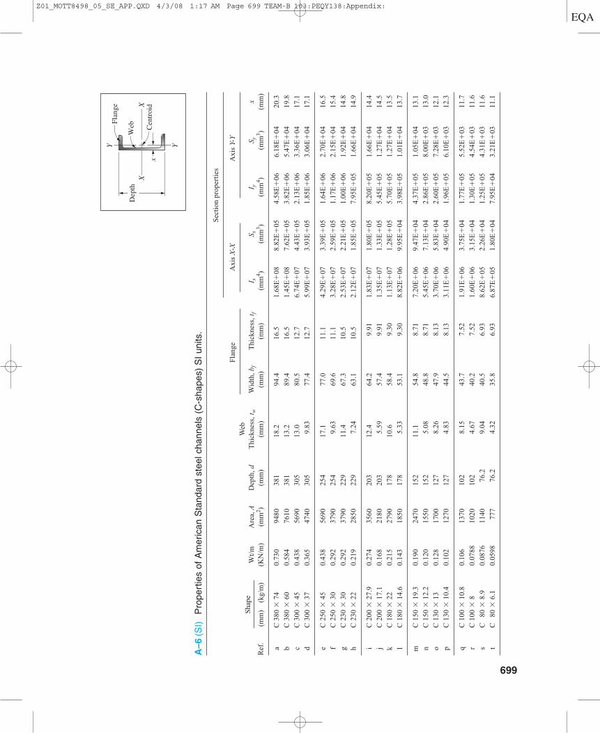
A–6
(SI)
Pro
pert
ies
of A
mer
ican
Sta
ndar
d st
eel c
hann
els
(C-s
hape
s) S
I un
its.
Sec
tion
pro
pert
ies
Web
F
lang
eA
xis
X-X
Axi
s Y-
Y
Sha
peW
t/m
Are
a, A
Dep
th, d
Thi
ckne
ss, t
wW
idth
, bf
Thi
ckne
ss, t
fI x
S xI y
S yx
Ref
.(m
m)
(kg/
m)
(KN
/m)
(mm
2 )(m
m)
(mm
)(m
m)
(mm
)(m
m4 )
(mm
3 )(m
m4 )
(mm
3 )(m
m)
aC
380
�74
0.73
094
8038
118
.294
.416
.51.
68E
�08
8.82
E�
054.
58E
�06
6.18
E�
0420
.3
bC
380
�60
0.58
476
1038
113
.289
.416
.51.
45E
�08
7.62
E�
053.
82E
�06
5.47
E�
0419
.8
cC
300
�45
0.43
856
9030
513
.080
.512
.76.
74E
�07
4.43
E�
052.
13E
�06
3.36
E�
0417
.1
dC
300
�37
0.36
547
4030
59.
8377
.412
.75.
99E
�07
3.93
E�
051.
85E
�06
3.06
E�
0417
.1
eC
250
�45
0.43
856
9025
417
.177
.011
.14.
29E
�07
3.39
E�
051.
64E
�06
2.70
E�
0416
.5
fC
250
�30
0.29
237
9025
49.
6369
.611
.13.
28E
�07
2.59
E�
051.
17E
�06
2.15
E�
0415
.4
gC
230
�30
0.29
237
9022
911
.467
.310
.52.
53E
�07
2.21
E�
051.
00E
�06
1.92
E�
0414
.8
hC
230
�22
0.21
928
5022
97.
2463
.110
.52.
12E
�07
1.85
E�
057.
95E
�05
1.66
E�
0414
.9
iC
200
�27
.90.
274
3560
203
12.4
64.2
9.91
1.83
E�
071.
80E
�05
8.20
E�
051.
66E
�04
14.4
jC
200
�17
.10.
168
2180
203
5.59
57.4
9.91
1.35
E�
071.
33E
�05
5.45
E�
051.
27E
�04
14.5
kC
180
�22
0.21
527
9017
810
.658
.49.
301.
13E
�07
1.28
E�
055.
70E
�05
1.27
E�
0413
.5
lC
180
�14
.60.
143
1850
178
5.33
53.1
9.30
8.82
E�
069.
95E
�04
3.98
E�
051.
01E
�04
13.7
mC
150
�19
.30.
190
2470
152
11.1
54.8
8.71
7.20
E�
069.
47E
�04
4.37
E�
051.
05E
�04
13.1
nC
150
�12
.20.
120
1550
152
5.08
48.8
8.71
5.45
E�
067.
13E
�04
2.86
E�
058.
00E
�03
13.0
oC
130
�13
0.12
817
0012
78.
2647
.98.
133.
70E
�06
5.83
E�
042.
60E
�05
7.28
E�
0312
.1
pC
130
�10
.40.
102
1270
127
4.83
44.5
8.13
3.11
E�
064.
90E
�04
1.96
E�
056.
10E
�03
12.3
qC
100
�10
.80.
106
1370
102
8.15
43.7
7.52
1.91
E�
063.
75E
�04
1.77
E�
055.
52E
�03
11.7
rC
100
�8
0.07
8810
2010
24.
6740
.27.
521.
60E
�06
3.15
E�
041.
30E
�05
4.54
E�
0311
.6
sC
80
�8.
90.
0876
1140
76.2
9.04
40.5
6.93
8.62
E�
052.
26E
�04
1.25
E�
054.
31E
�03
11.6
tC
80
�6.
10.
0598
777
76.2
4.32
35.8
6.93
6.87
E�
051.
80E
�04
7.95
E�
043.
21E
�03
11.1
X
Y Y
X
xC
entr
oid
Web
Flan
ge
Dep
th
699
Z01_MOTT8498_05_SE_APP.QXD 4/3/08 1:17 AM Page 699 TEAM-B 103:PEQY138:Appendix:
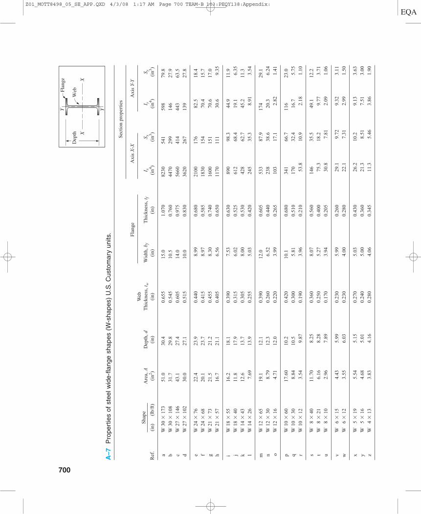
A–7
Pro
pert
ies
of s
teel
wid
e-fla
nge
shap
es (
W-s
hape
s) U
.S.C
usto
mar
y un
its.
Sec
tion
pro
pert
ies
Web
Fla
nge
Axi
s X
-XA
xis
Y-Y
Sha
peA
rea,
AD
epth
, dT
hick
ness
, tw
Wid
th, b
fT
hick
ness
,tf
I xS x
I yS y
Ref
.(i
n)(l
b/ft
)(i
n2 )(i
n)(i
n)(i
n)(i
n)(i
n4 )(i
n3 )(i
n4 )(i
n3 )
aW
30
� 1
7351
.030
.40.
655
15.0
1.07
082
3054
159
879
.8
bW
30
�10
831
.729
.80.
545
10.5
0.76
044
7029
914
627
.9
cW
27
�14
643
.127
.40.
605
14.0
0.97
556
6041
444
363
.5
dW
27
�10
230
.027
.10.
515
10.0
0.83
036
2026
713
927
.8
eW
24
�76
22.4
23.9
0.44
08.
990.
680
2100
176
82.5
18.4
fW
24
�68
20.1
23.7
0.41
58.
970.
585
1830
154
70.4
15.7
gW
21
�73
21.5
21.2
0.45
58.
300.
740
1600
151
70.6
17.0
hW
21
�57
16.7
21.1
0.40
56.
560.
650
1170
111
30.6
9.35
i W
18
�55
16.2
18.1
0.39
07.
530.
630
890
98.3
44.9
11.9
jW
18
�40
11.8
17.9
0.31
56.
020.
525
612
68.4
19.1
6.35
kW
14
�43
12.6
13.7
0.30
58.
000.
530
428
62.7
45.2
11.3
lW
14
�26
7.69
13.9
0.25
55.
030.
420
245
35.3
8.91
3.54
mW
12
�65
19.1
12.1
0.39
012
.00.
605
533
87.9
174
29.1
nW
12
�30
8.79
12.3
0.26
06.
520.
440
238
38.6
20.3
6.24
oW
12
�16
4.71
12.0
0.22
03.
990.
265
103
17.1
2.82
1.41
pW
10
�60
17.6
010
.20.
420
10.1
0.68
034
166
.711
623
.0
qW
10
�30
8.84
10.5
0.30
05.
810.
510
170
32.4
16.7
5.75
rW
10
�12
3.54
9.87
0.19
03.
960.
210
53.8
10.9
2.18
1.10
sW
8
�40
11.7
08.
250.
360
8.07
0.56
014
635
.549
.112
.2
tW
8
�21
6.16
8.28
0.25
05.
270.
400
75.3
18.2
9.77
3.71
uW
8
�10
2.96
7.89
0.17
03.
940.
205
30.8
7.81
2.09
1.06
vW
6
�15
4.43
5.99
0.23
05.
990.
260
29.1
9.72
9.32
3.11
wW
6
�12
3.55
6.03
0.23
04.
000.
280
22.1
7.31
2.99
1.50
xW
5
�19
5.54
5.15
0.27
05.
030.
430
26.2
10.2
9.13
3.63
yW
5
�16
4.68
5.01
0.24
05.
000.
360
21.3
8.51
7.51
3.00
zW
4
�13
3.83
4.16
0.28
04.
060.
345
11.3
5.46
3.86
1.90
700
Flan
ge
Dep
thW
eb
XX
YY
Z01_MOTT8498_05_SE_APP.QXD 4/3/08 1:17 AM Page 700 TEAM-B 103:PEQY138:Appendix:
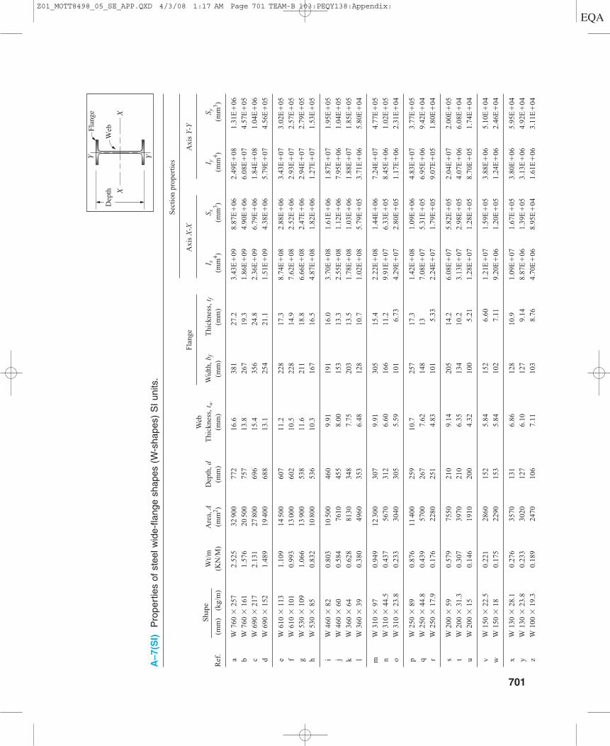
A–7(S
I)P
rope
rtie
s of
ste
el w
ide-
flang
e sh
apes
(W
-sha
pes)
SI
units
.
Sec
tion
pro
pert
ies
Web
Fla
nge
Axi
s X
-XA
xis
Y-Y
Sha
peW
t/m
Are
a, A
Dep
th, d
Thi
ckne
ss, t
wW
idth
, bf
Thi
ckne
ss, t
fI x
S xI y
S yR
ef.
(mm
)(k
g/m
)(K
N/M
)(m
m2 )
(mm
)(m
m)
(mm
)(m
m)
(mm
4 )(m
m3 )
(mm
4 )(m
m3 )
aW
760
�25
72.
525
3290
077
216
.638
127
.23.
43E
�09
8.87
E�
062.
49E
�08
1.31
E�
06
bW
760
�16
11.
576
2050
075
713
.826
719
.31.
86E
�09
4.90
E�
066.
08E
�07
4.57
E�
05
cW
690
�21
72.
131
2780
069
615
.435
624
.82.
36E
�09
6.79
E�
061.
84E
�08
1.04
E�
06
dW
690
�15
21.
489
1940
068
813
.125
421
.11.
51E
�09
4.38
E�
065.
79E
�07
4.56
E�
05
eW
610
�11
31.
109
1450
060
711
.222
817
.38.
74E
�08
2.88
E�
063.
43E
�07
3.02
E�
05
fW
610
�10
10.
993
1300
060
210
.522
814
.97.
62E
�08
2.52
E�
062.
93E
�07
2.57
E�
05
gW
530
�10
91.
066
1390
053
811
.621
118
.86.
66E
�08
2.47
E�
062.
94E
�07
2.79
E�
05
hW
530
�85
0.83
210
800
536
10.3
167
16.5
4.87
E�
081.
82E
�06
1.27
E�
071.
53E
�05
iW
460
�82
0.80
310
500
460
9.91
191
16.0
3.70
E�
081.
61E
�06
1.87
E�
071.
95E
�05
jW
460
�60
0.58
476
1045
58.
0015
313
.32.
55E
�08
1.12
E�
067.
95E
�06
1.04
E�
05
kW
360
�64
0.62
881
3034
87.
7520
313
.51.
78E
�08
1.03
E�
061.
88E
�07
1.85
E�
05
lW
360
�39
0.38
049
6035
36.
4812
810
.71.
02E
�08
5.79
E�
053.
71E
�06
5.80
E�
04
mW
310
�97
0.94
912
300
307
9.91
305
15.4
2.22
E�
081.
44E
�06
7.24
E�
074.
77E
�05
nW
310
�44
.50.
437
5670
312
6.60
166
11.2
9.91
E�
076.
33E
�05
8.45
E�
061.
02E
�05
oW
310
�23
.80.
233
3040
305
5.59
101
6.73
4.29
E�
072.
80E
�05
1.17
E�
062.
31E
�04
pW
250
�89
0.87
611
400
259
10.7
257
17.3
1.42
E�
081.
09E
�06
4.83
E�
073.
77E
�05
qW
250
�44
.80.
439
5700
267
7.62
148
137.
08E
�07
5.31
E�
056.
95E
�06
9.42
E�
04
rW
250
�17
.90.
176
2280
251
4.83
101
5.33
2.24
E�
071.
79E
�05
9.07
E�
051.
80E
�04
sW
200
�59
0.57
975
5021
09.
1420
514
.26.
08E
�07
5.82
E�
052.
04E
�07
2.00
E�
05
tW
200
�31
.30.
307
3970
210
6.35
134
10.2
3.13
E�
072.
98E
�05
4.07
E�
066.
08E
�04
uW
200
�15
0.14
619
1020
04.
3210
05.
211.
28E
�07
1.28
E�
058.
70E
�05
1.74
E�
04
vW
150
�22
.50.
221
2860
152
5.84
152
6.60
1.21
E�
071.
59E
�05
3.88
E�
065.
10E
�04
wW
150
�18
0.17
522
9015
35.
8410
27.
119.
20E
�06
1.20
E�
051.
24E
�06
2.46
E�
04
xW
130
�28
.10.
276
3570
131
6.86
128
10.9
1.09
E�
071.
67E
�05
3.80
E�
065.
95E
�04
yW
130
�23
.80.
233
3020
127
6.10
127
9.14
8.87
E�
061.
39E
�05
3.13
E�
064.
92E
�04
zW
100
�19
.30.
189
2470
106
7.11
103
8.76
4.70
E�
068.
95E
�04
1.61
E�
063.
11E
�04
Flan
ge
Dep
thW
eb
XX
YY
701
Z01_MOTT8498_05_SE_APP.QXD 4/3/08 1:17 AM Page 701 TEAM-B 103:PEQY138:Appendix:
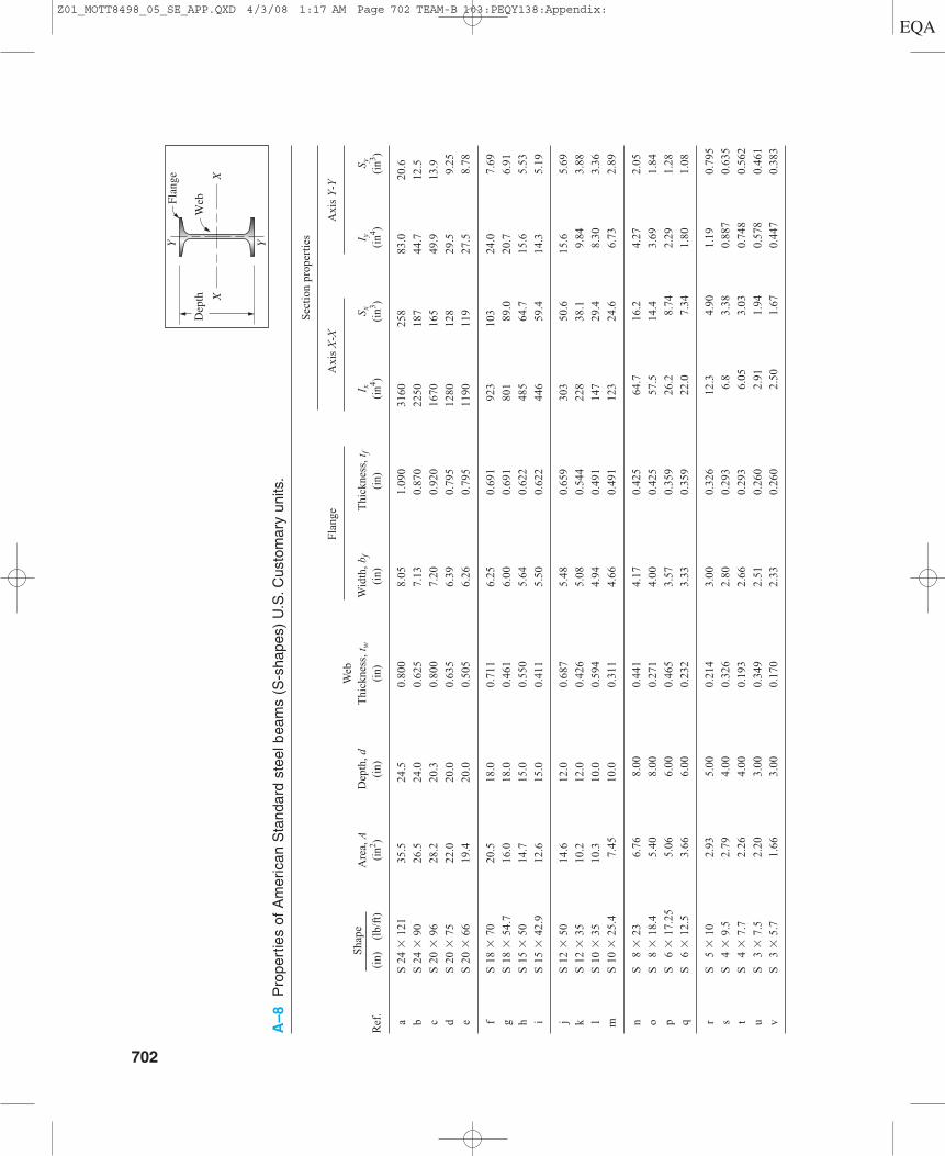
A–8
Pro
pert
ies
of A
mer
ican
Sta
ndar
d st
eel b
eam
s (S
-sha
pes)
U.S
.Cus
tom
ary
units
.
Sec
tion
pro
pert
ies
Web
Fla
nge
Axi
s X
-XA
xis
Y-Y
Sha
peA
rea,
AD
epth
, dT
hick
ness
, tw
Wid
th, b
fT
hick
ness
, tf
I xS x
I yS y
Ref
.(i
n)(l
b/ft
)(i
n2 )(i
n)(i
n)(i
n)(i
n)(i
n4 )(i
n3 )(i
n4 )(i
n3 )
aS
24
�12
135
.524
.50.
800
8.05
1.09
031
6025
883
.020
.6
bS
24
�90
26.5
24.0
0.62
57.
130.
870
2250
187
44.7
12.5
cS
20
�96
28.2
20.3
0.80
07.
200.
920
1670
165
49.9
13.9
dS
20
�75
22.0
20.0
0.63
56.
390.
795
1280
128
29.5
9.25
eS
20
�66
19.4
20.0
0.50
56.
260.
795
1190
119
27.5
8.78
fS
18
�70
20.5
18.0
0.71
16.
250.
691
923
103
24.0
7.69
gS
18
�54
.716
.018
.00.
461
6.00
0.69
180
189
.020
.76.
91
hS
15
�50
14.7
15.0
0.55
05.
640.
622
485
64.7
15.6
5.53
iS
15
�42
.912
.615
.00.
411
5.50
0.62
244
659
.414
.35.
19
jS
12
�50
14.6
12.0
0.68
75.
480.
659
303
50.6
15.6
5.69
kS
12
�35
10.2
12.0
0.42
65.
080.
544
228
38.1
9.84
3.88
lS
10
�35
10.3
10.0
0.59
44.
940.
491
147
29.4
8.30
3.36
mS
10
�25
.47.
4510
.00.
311
4.66
0.49
112
324
.66.
732.
89
nS
8 �
236.
768.
000.
441
4.17
0.42
564
.716
.24.
272.
05
oS
8
�18
.45.
408.
000.
271
4.00
0.42
557
.514
.43.
691.
84
pS
6
�17
.25
5.06
6.00
0.46
53.
570.
359
26.2
8.74
2.29
1.28
qS
6
�12
.53.
666.
000.
232
3.33
0.35
922
.07.
341.
801.
08
rS
5
�10
2.93
5.00
0.21
43.
000.
326
12.3
4.90
1.19
0.79
5
sS
4
�9.
52.
794.
000.
326
2.80
0.29
36.
83.
380.
887
0.63
5
tS
4
�7.
72.
264.
000.
193
2.66
0.29
36.
053.
030.
748
0.56
2
uS
3
�7.
52.
203.
000.
349
2.51
0.26
02.
911.
940.
578
0.46
1
vS
3
�5.
71.
663.
000.
170
2.33
0.26
02.
501.
670.
447
0.38
3
702
Flan
ge
Dep
thW
eb
XX
YY
Z01_MOTT8498_05_SE_APP.QXD 4/3/08 1:17 AM Page 702 TEAM-B 103:PEQY138:Appendix:

A–8(S
I)P
rope
rtie
s of
Am
eric
an S
tand
ard
stee
l bea
ms
(S-s
hape
s) S
I un
its.
Sec
tion
pro
pert
ies
Web
Fla
nge
Axi
s X
-XA
xis
Y-Y
Sha
peW
t/m
Are
a, A
Dep
th, d
Thi
ckne
ss, t
wW
idth
,bf
Thi
ckne
ss, t
fI x
S xI y
S yR
ef.
(mm
)(k
g/m
)(K
N/m
)(m
m2 )
(mm
)(m
m)
(mm
)(m
m)
(mm
4 )(m
m3 )
(mm
4 )(m
m3 )
aS
610
�18
01.
766
2290
062
220
.320
427
.71.
32E
�09
4.23
E�
063.
45E
�07
3.38
E�
05
bS
610
�13
41.
314
1710
061
015
.918
122
.19.
36E
�08
3.06
E�
061.
86E
�07
2.05
E�
05
cS
510
�14
31.
401
1820
051
620
.318
323
.46.
95E
�08
2.70
E�
062.
08E
�07
2.28
E�
05
dS
510
�11
21.
095
1420
050
816
.116
220
.25.
33E
�08
2.10
E�
061.
23E
�07
1.52
E�
05
eS
510
�98
.20.
963
1250
050
812
.815
920
.24.
95E
�08
1.95
E�
061.
14E
�07
1.44
E�
05
fS
460
�10
41.
022
1320
045
718
.115
917
.63.
84E
�08
1.69
E�
069.
99E
�06
1.26
E�
05
gS
460
�81
.40.
799
1030
045
711
.715
217
.63.
33E
�08
1.46
E�
068.
62E
�06
1.13
E�
05
hS
380
�74
0.73
094
8038
114
.014
315
.82.
02E
�08
1.06
E�
066.
49E
�06
9.06
E�
04
iS
380
�64
0.62
681
3038
110
.414
015
.81.
86E
�08
9.74
E�
055.
95E
�06
8.51
E�
04
jS
300
�74
0.73
094
2030
517
.413
916
.71.
26E
�08
8.29
E�
056.
49E
�06
9.33
E�
04
kS
300
�52
0.51
165
8030
510
.812
913
.89.
49E
�07
6.24
E�
054.
10E
�06
6.36
E�
04
lS
250
�52
0.51
166
5025
415
.112
512
.56.
12E
�07
4.82
E�
053.
45E
�06
5.51
E�
04
mS
250
�37
.80.
371
4810
254
7.9
118
12.5
5.12
E�
074.
03E
�05
2.80
E�
064.
74E
�04
nS
200
�34
0.33
643
6020
311
.210
610
.82.
69E
�07
2.66
E�
051.
78E
�06
3.36
E�
04
oS
200
�27
.40.
269
3480
203
6.9
102
10.8
2.39
E�
072.
36E
�05
1.54
E�
063.
02E
�04
pS
150
�25
.70.
252
3260
152
11.8
90.7
9.1
1.09
E�
071.
43E
�05
9.53
E�
052.
10E
�04
qS
150
�18
.60.
182
2360
152
5.9
84.6
9.1
9.16
E�
061.
20E
�05
7.49
E�
051.
77E
�04
rS
130
�15
0.14
618
9012
75.
476
.28.
35.
12E
�06
8.03
E�
044.
95E
�05
1.30
E�
04
sS
100
�14
.10.
138
1800
102
8.3
71.1
7.4
2.81
E�
065.
54E
�04
3.69
E�
051.
04E
�04
tS
100
�11
.50.
113
1460
102
4.9
67.6
7.4
2.52
E�
064.
97E
�04
3.11
E�
059.
21E
�03
uS
80
�11
.20.
110
1420
76.2
8.9
63.8
6.6
1.21
E�
063.
18E
�04
2.41
E�
057.
56E
�03
vS
80
�8.
50.
083
1070
76.2
4.3
59.2
6.6
1.04
E�
062.
74E
�04
1.86
E�
056.
28E
�03
Flan
ge
Dep
thW
eb
XX
YY
703
Z01_MOTT8498_05_SE_APP.QXD 4/3/08 1:17 AM Page 703 TEAM-B 103:PEQY138:Appendix:
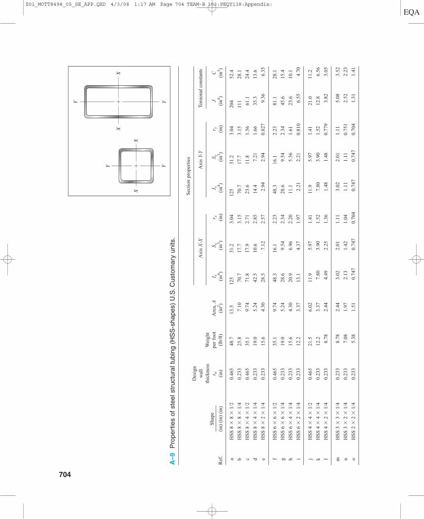
A–9
Pro
pert
ies
of s
teel
str
uctu
ral t
ubin
g (H
SS
-sha
pes)
U.S
.Cus
tom
ary
units
.
Des
ign
Sec
tion
pro
pert
ies
wal
lth
ickn
ess
Wei
ght
Axi
s X
-XA
xis
Y-Y
Tors
iona
l con
stan
ts
Sha
pet w
per
foot
Are
a, A
I xS x
r xI y
S yr y
JC
Ref
. (i
n) (
in)
(in)
(in)
(lb/
ft)
(in2 )
(in4 )
(in3 )
(in)
(in4 )
(in3 )
(in)
(in4 )
(in3 )
aH
SS
8 �
8 �
1/2
0.46
548
.713
.512
531
.23.
0412
531
.23.
0420
452
.4
bH
SS
8 �
8 �
1/4
0.23
325
.87.
1070
.717
.73.
1570
.717
.73.
1511
128
.1
cH
SS
8 �
4 �
1/2
0.46
535
.19.
7471
.817
.92.
7123
.611
.81.
5661
.124
.4
dH
SS
8 �
4 �
1/4
0.23
319
.05.
2442
.510
.62.
8514
.47.
211.
6635
.313
.6
eH
SS
8 �
2 �
1/4
0.23
315
.64.
3028
.57.
122.
572.
942.
940.
827
9.36
6.35
fH
SS
6 �
6 �
1/2
0.46
535
.19.
7448
.316
.12.
2348
.316
.12.
2381
.128
.1
gH
SS
6 �
6 �
1/4
0.23
319
.05.
2428
.69.
542.
3428
.69.
542.
3445
.615
.4
hH
SS
6 �
4 �
1/4
0.23
315
.64.
3020
.96.
962.
2011
.15.
561.
6123
.610
.1
iH
SS
6 �
2 �
1/4
0.23
312
.23.
3713
.14.
371.
972.
212.
210.
810
6.55
4.70
jH
SS
4 �
4 �
1/2
0.46
521
.56.
0211
.95.
971.
4111
.95.
971.
4121
.011
.2
kH
SS
4 �
4 �
1/4
0.23
312
.23.
377.
803.
901.
527.
803.
901.
5212
.86.
56
lH
SS
4 �
2 �
1/4
0.23
38.
782.
444.
492.
251.
361.
481.
480.
779
3.82
3.05
mH
SS
3 �
3 �
1/4
0.23
38.
782.
443.
022.
011.
113.
022.
011.
115.
083.
52
nH
SS
3 �
2 �
1/4
0.23
37.
081.
972.
131.
421.
041.
111.
110.
751
2.52
2.23
oH
SS
2 �
2 �
1/4
0.23
35.
381.
510.
747
0.74
70.
704
0.74
70.
747
0.70
41.
311.
41
704
XX
XX
Y
Y YY
Z01_MOTT8498_05_SE_APP.QXD 4/3/08 1:17 AM Page 704 TEAM-B 103:PEQY138:Appendix:
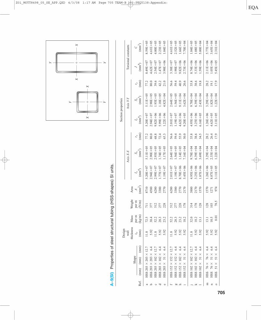
A–9(S
I)P
rope
rtie
s of
ste
el s
truc
tura
l tub
ing
(HS
S-s
hape
s) S
I un
its.
Des
ign
Sec
tion
pro
pert
ies
wal
l th
ickn
ess
Mas
sW
eigh
tA
rea
Axi
s X
-XA
xis
Y-Y
Tors
iona
l co
nsta
nts
Sha
pet w
per
mpe
r m
AI x
S xr x
I yS y
r yJ
CR
ef.
(mm
) (m
m)
(mm
)(m
m)
(kg/
m)
(N/m
)(m
m2 )
(mm
4 )(m
m3 )
(mm
)(m
m4 )
(mm
3 )(m
m)
(mm
4 )(m
m3 )
aH
SS
203
�20
3 �
12.7
11.8
72.5
711
8710
5.20
E�
075.
11E
�05
77.2
5.20
E�
075.
11E
�05
77.2
8.49
E�
078.
59E
�05
bH
SS
203
�20
3 �
6.4
5.92
38.4
377
4580
2.94
E�
072.
90E
�05
80.0
2.94
E�
072.
90E
�05
80.0
4.62
E�
074.
61E
�05
cH
SS
203
�10
2 �
12.7
11.8
52.2
512
6280
2.99
E�
072.
93E
�05
68.8
9.82
E�
061.
93E
�05
39.6
2.54
E�
074.
00E
�05
dH
SS
203
�10
2 �
6.4
5.92
28.3
277
3380
1.77
E�
071.
74E
�05
72.4
5.99
E�
061.
18E
�05
42.2
1.47
E�
072.
23E
�05
eH
SS
203
�51
�6.
45.
9223
.222
827
701.
19E
�07
1.17
E�
0565
.31.
22E
�06
4.82
E�
0421
.03.
90E
�06
1.04
E�
05
fH
SS
152
�15
2 �
12.7
11.8
52.2
512
6280
2.01
E�
072.
64E
�05
56.6
2.01
E�
072.
64E
�05
56.6
3.38
E�
074.
61E
�05
gH
SS
152
�15
2 �
6.4
5.92
28.3
277
3380
1.19
E�
071.
56E
�05
59.4
1.19
E�
071.
56E
�05
59.4
1.90
E�
072.
52E
�05
hH
SS
152
�10
2 �
6.4
5.92
23.2
228
2770
8.70
E�
061.
14E
�05
55.9
4.62
E�
069.
11E
�04
40.9
9.82
E�
061.
66E
�05
iH
SS
152
�51
�6.
45.
9218
.217
821
705.
45E
�06
7.16
E�
0450
.09.
20E
�05
3.62
E�
0420
.62.
73E
�06
7.70
E�
04
jH
SS
102
�10
2 �
12.7
11.8
32.0
314
3880
4.95
E�
069.
78E
�04
35.8
4.95
E�
069.
78E
�04
35.8
8.74
E�
061.
84E
�05
kH
SS
102
�10
2 �
6.4
5.92
18.2
178
2170
3.25
E�
066.
39E
�04
38.6
3.25
E�
066.
39E
�04
38.6
5.33
E�
061.
08E
�05
lH
SS
102
�51
�6.
45.
9213
.112
815
701.
87E
�06
3.69
E�
0434
.56.
16E
�05
2.43
E�
0419
.81.
59E
�06
5.00
E�
04
mH
SS
76
�76
�6.
45.
9213
.112
815
701.
26E
�06
3.29
E�
0428
.21.
26E
�06
3.29
E�
0428
.22.
11E
�06
5.77
E�
04
nH
SS
76
�51
�6.
45.
9210
.510
312
718.
87E
�05
2.33
E�
0426
.44.
62E
�05
1.82
E�
0419
.11.
05E
�06
3.65
E�
04
oH
SS
51
�51
�6.
45.
928.
0178
.597
43.
11E
�05
1.22
E�
0417
.93.
11E
�05
1.22
E�
0417
.95.
45E
�05
2.31
E�
04
XX
XX
Y
Y YY
705
Z01_MOTT8498_05_SE_APP.QXD 4/3/08 1:17 AM Page 705 TEAM-B 103:PEQY138:Appendix:
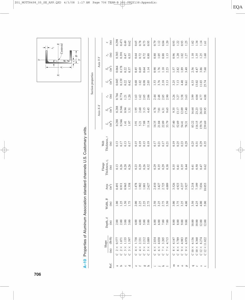
A–10
Pro
pert
ies
of A
lum
inum
Ass
ocia
tion
stan
dard
cha
nnel
s U
.S.C
usto
mar
y un
its.
Sec
tion
pro
pert
ies
Fla
nge
Web
Axi
s X
-XA
xis
Y-Y
Sha
peD
epth
,AW
idth
, BA
rea
Thi
ckne
ss, t
1T
hick
ness
, tI x
S xr x
I yS y
r yx
Ref
. (i
n)(l
b/ft
)(i
n)(i
n)(i
n2 )(i
n)(i
n)(i
n4 )(i
n3 )(i
n)(i
n4 )(i
n3 )(i
n)(i
n)
aC
2
�0.
577
2.00
1.00
0.49
10.
130.
130.
288
0.28
80.
766
0.04
50.
064
0.30
30.
298
bC
2
�1.
071
2.00
1.25
0.91
10.
260.
170.
546
0.54
60.
774
0.13
90.
178
0.39
10.
471
cC
3
�1.
135
3.00
1.50
0.96
50.
200.
131.
410.
941.
210.
220.
220.
470.
49
dC
3
�1.
597
3.00
1.75
1.35
80.
260.
171.
971.
311.
200.
420.
370.
550.
62
eC
4
�1.
738
4.00
2.00
1.47
80.
230.
153.
911.
951.
630.
600.
450.
640.
65
fC
4
�2.
331
4.00
2.25
1.98
20.
290.
195.
212.
601.
621.
020.
690.
720.
78
gC
5
�2.
212
5.00
2.25
1.88
10.
260.
157.
883.
152.
050.
980.
640.
720.
73
hC
5
�3.
089
5.00
2.75
2.62
70.
320.
1911
.14
4.45
2.06
2.05
1.14
0.88
0.95
i C
6
�2.
834
6.00
2.50
2.41
00.
290.
1714
.35
4.78
2.44
1.53
0.90
0.80
0.79
jC
6
�4.
030
6.00
3.25
3.42
70.
350.
2121
.04
7.01
2.48
3.76
1.76
1.05
1.12
kC
7
�3.
205
7.00
2.75
2.72
50.
290.
1722
.09
6.31
2.85
2.10
1.10
0.88
0.84
lC
7
�4.
715
7.00
3.50
4.00
90.
380.
2133
.79
9.65
2.90
5.13
2.23
1.13
1.20
mC
8
�4.
147
8.00
3.00
3.52
60.
350.
1937
.40
9.35
3.26
3.25
1.57
0.96
0.93
nC
8
�5.
789
8.00
3.75
4.92
30.
410.
2552
.69
13.1
73.
277.
132.
821.
201.
22
oC
9
�4.
983
9.00
3.25
4.23
70.
350.
2354
.41
12.0
93.
584.
401.
891.
020.
93
pC
9
�6.
970
9.00
4.00
5.92
70.
440.
2978
.31
17.4
03.
639.
613.
491.
271.
25
qC
10
�6.
136
10.0
03.
505.
218
0.41
0.25
83.2
216
.64
3.99
6.33
2.56
1.10
1.02
rC
10
�8.
360
10.0
04.
257.
109
0.50
0.31
116.
1523
.23
4.04
13.0
24.
471.
351.
34
sC
12
�8.
274
12.0
04.
007.
036
0.47
0.29
159.
7626
.63
4.77
11.0
33.
861.
251.
14
tC
12
�11
.822
12.0
05.
0010
.053
0.62
0.35
239.
6939
.95
4.88
25.7
47.
601.
601.
61
706
XC
entr
oid
YY
XA
R
B
t 1t x
Z01_MOTT8498_05_SE_APP.QXD 4/3/08 1:17 AM Page 706 TEAM-B 103:PEQY138:Appendix:
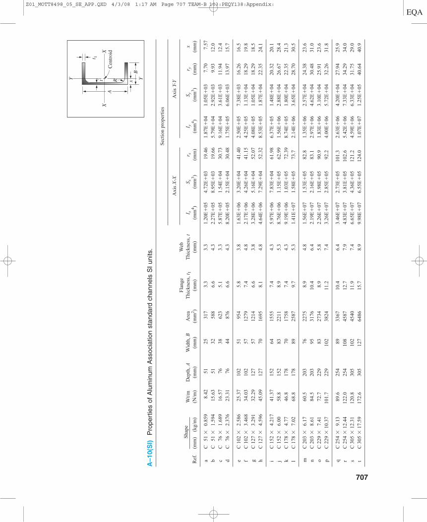
A–10(S
I)P
rope
rtie
s of
Alu
min
um A
ssoc
iatio
n st
anda
rd c
hann
els
SI
units
.
Sec
tion
pro
pert
ies
Fla
nge
Web
A
xis
X-X
Axi
s Y-
Y
Sha
peW
t/m
Dep
th, A
Wid
th, B
Are
aT
hick
ness
, t1
Thi
ckne
ss, t
I xS x
r xI y
S yr y
xR
ef.
(mm
)(k
g/m
)(N
/m)
(mm
)(m
m)
(mm
2 )(m
m)
(mm
)(m
m4 )
(mm
3 )(m
m)
(mm
4 )(m
m3 )
(mm
)(m
m)
aC
51
�0.
859
8.42
5125
317
3.3
3.3
1.20
E�
054.
72E
�03
19.4
61.
87E
�04
1.05
E�
037.
707.
57
bC
51
�
1.59
415
.63
5132
588
6.6
4.3
2.27
E�
058.
95E
�03
19.6
65.
79E
�04
2.92
E�
039.
9312
.0
cC
76
�
1.68
916
.57
7638
623
5.1
3.3
5.87
E�
051.
54E
�04
30.7
39.
16E
�04
3.61
E�
0311
.94
12.4
dC
76
�2.
376
23.3
176
4487
66.
64.
38.
20E
�05
2.15
E�
0430
.48
1.75
E�
056.
06E
�03
13.9
715
.7
eC
102
�
2.58
625
.37
102
5195
45.
83.
81.
63E
�06
3.20
E�
0441
.40
2.50
E�
057.
38E
�03
16.2
616
.5
fC
102
�
3.46
834
.03
102
5712
797.
44.
82.
17E
�06
4.26
E�
0441
.15
4.25
E�
051.
13E
�04
18.2
919
.8
gC
127
�
3.29
132
.29
127
5712
146.
63.
83.
28E
�06
5.16
E�
0452
.07
4.08
E�
051.
05E
�04
18.2
918
.5
hC
127
�
4.59
645
.09
127
7016
958.
14.
84.
64E
�06
7.29
E�
0452
.32
8.53
E�
051.
87E
�04
22.3
524
.1
iC
152
�
4.21
741
.37
152
6415
557.
44.
35.
97E
�06
7.83
E�
0461
.98
6.37
E�
051.
48E
�04
20.3
220
.1
jC
152
�
6.00
58.8
152
8322
118.
95.
38.
76E
�06
1.15
E�
0562
.99
1.56
E�
062.
88E
�04
26.6
728
.4
kC
178
�
4.77
46.8
178
7017
587.
44.
39.
19E
�06
1.03
E�
0572
.39
8.74
E�
051.
80E
�04
22.3
521
.3
lC
178
�
7.02
68.8
178
8925
879.
75.
31.
41E
�07
1.58
E�
0573
.72.
14E
�06
3.65
E�
0428
.70
30.5
mC
203
�
6.17
60.5
203
7622
758.
94.
81.
56E
�07
1.53
E�
0582
.81.
35E
�06
2.57
E�
0424
.38
23.6
nC
203
�
8.61
84.5
203
9531
7610
.46.
42.
19E
�07
2.16
E�
0583
.12.
97E
�06
4.62
E�
0430
.48
31.0
oC
229
�
7.41
72.7
229
8327
348.
95.
82.
26E
�07
1.98
E�
0590
.91.
83E
�06
3.10
E�
0425
.91
23.6
pC
229
� 1
0.37
101.
722
910
238
2411
.27.
43.
26E
�07
2.85
E�
0592
.24.
00E
�06
5.72
E�
0432
.26
31.8
qC
254
�
9.13
89.6
254
8933
6710
.46.
43.
46E
�07
2.73
E�
0510
1.3
2.63
E�
064.
20E
�04
27.9
425
.9
rC
254
� 1
2.44
122.
025
410
845
8712
.77.
94.
83E
�07
3.81
E�
0510
2.6
5.42
E�
067.
33E
�04
34.2
934
.0
sC
305
� 1
2.31
120.
830
510
245
4011
.97.
46.
65E
�07
4.36
E�
0512
1.2
4.59
E�
066.
33E
�04
31.7
529
.0
tC
305
� 1
7.59
172.
630
512
764
8615
.78.
99.
98E
�07
6.55
E�
0512
4.0
1.07
E�
071.
25E
�05
40.6
440
.9
XC
entr
oid
YY
XA
R
B
t 1t x
707
Z01_MOTT8498_05_SE_APP.QXD 4/3/08 1:17 AM Page 707 TEAM-B 103:PEQY138:Appendix:
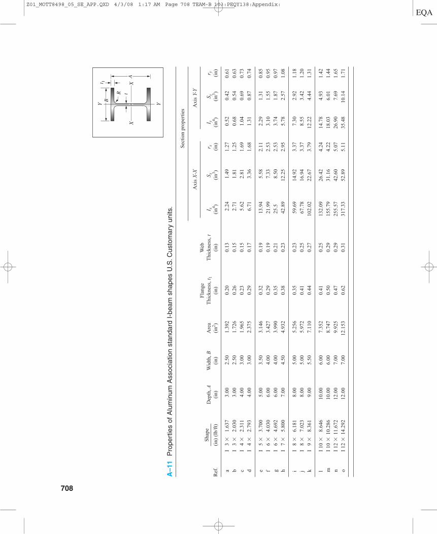
A–11
Pro
pert
ies
of A
lum
inum
Ass
ocia
tion
stan
dard
I-b
eam
sha
pes
U.S
.Cus
tom
ary
units
.
Sec
tion
pro
pert
ies
Fla
nge
Web
Axi
s X
-XA
xis
Y-Y
Sha
peD
epth
,AW
idth
, BA
rea
Thi
ckne
ss, t
1T
hick
ness
, tI x
S xr x
I yS y
r yR
ef.
(in)
(lb
/ft)
(in)
(in)
(in2 )
(in)
(in)
(in4 )
(in3 )
(in)
(in4 )
(in3 )
(in)
aI
3 �
1.63
73.
002.
501.
392
0.20
0.13
2.24
1.49
1.27
0.52
0.42
0.61
bI
3 �
2.03
03.
002.
501.
726
0.26
0.15
2.71
1.81
1.25
0.68
0.54
0.63
cI
4 �
2.31
14.
003.
001.
965
0.23
0.15
5.62
2.81
1.69
1.04
0.69
0.73
dI
4 �
2.79
34.
003.
002.
375
0.29
0.17
6.71
3.36
1.68
1.31
0.87
0.74
eI
5 �
3.70
05.
003.
503.
146
0.32
0.19
13.9
45.
582.
112.
291.
310.
85
fI
6 �
4.03
06.
004.
003.
427
0.29
0.19
21.9
97.
332.
533.
101.
550.
95
gI
6 �
4.69
26.
004.
003.
990
0.35
0.21
25.5
8.50
2.53
3.74
1.87
0.97
hI
7 �
5.80
07.
004.
504.
932
0.38
0.23
42.8
912
.25
2.95
5.78
2.57
1.08
iI
8 �
6.18
18.
005.
005.
256
0.35
0.23
59.6
914
.92
3.37
7.30
2.92
1.18
jI
8 �
7.02
38.
005.
005.
972
0.41
0.25
67.7
816
.94
3.37
8.55
3.42
1.20
kI
9 �
8.36
19.
005.
507.
110
0.44
0.27
102.
0222
.67
3.79
12.2
24.
441.
31
lI
10 �
8.64
610
.00
6.00
7.35
20.
410.
2513
2.09
26.4
24.
2414
.78
4.93
1.42
mI
10 �
10.2
8610
.00
6.00
8.74
70.
500.
2915
5.79
31.1
64.
2218
.03
6.01
1.44
nI
12 �
11.6
7212
.00
7.00
9.92
50.
470.
2925
5.57
42.6
05.
0726
.90
7.69
1.65
oI
12 �
14.2
9212
.00
7.00
12.1
530.
620.
3131
7.33
52.8
95.
1135
.48
10.1
41.
71
708
XA
X
R t
t 1
YYB
Z01_MOTT8498_05_SE_APP.QXD 4/3/08 1:17 AM Page 708 TEAM-B 103:PEQY138:Appendix:
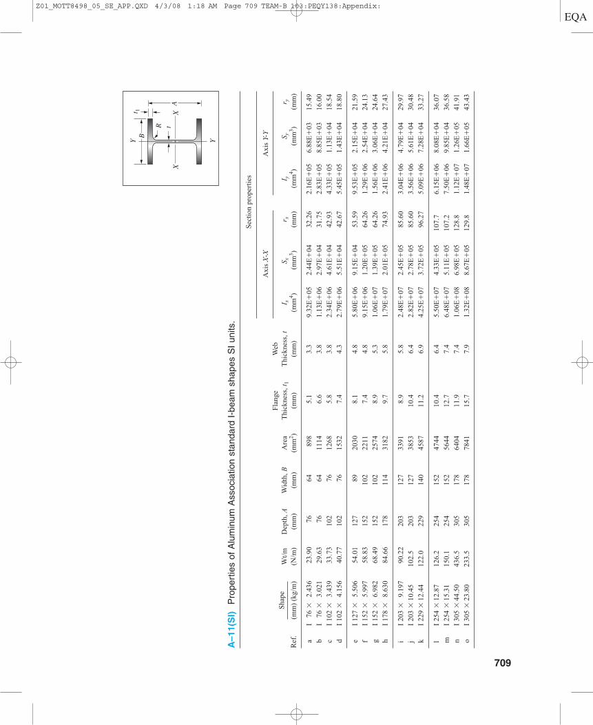
A–11(S
I)P
rope
rtie
s of
Alu
min
um A
ssoc
iatio
n st
anda
rd I
-bea
m s
hape
s S
I un
its.
Sec
tion
pro
pert
ies
Fla
nge
Web
Axi
s X
-XA
xis
Y-Y
Sha
peW
t/m
Dep
th, A
Wid
th, B
Are
aT
hick
ness
, t1
Thi
ckne
ss, t
I xS x
r x
I yS y
r yR
ef.
(mm
) (k
g/m
)(N
/m)
(mm
)(m
m)
(mm
2 )(m
m)
(mm
)(m
m4 )
(mm
3 )(m
m)
(mm
4 )(m
m3 )
(mm
)
aI
76 �
2.43
623
.90
7664
898
5.1
3.3
9.32
E�
052.
44E
�04
32.2
62.
16E
�05
6.88
E�
0315
.49
bI
76 �
3.02
129
.63
7664
1114
6.6
3.8
1.13
E�
062.
97E
�04
31.7
52.
83E
�05
8.85
E�
0316
.00
cI
102
�3.
439
33.7
310
276
1268
5.8
3.8
2.34
E�
064.
61E
�04
42.9
34.
33E
�05
1.13
E�
0418
.54
dI
102
�4.
156
40.7
710
276
1532
7.4
4.3
2.79
E�
065.
51E
�04
42.6
75.
45E
�05
1.43
E�
0418
.80
eI
127
�5.
506
54.0
112
789
2030
8.1
4.8
5.80
E�
069.
15E
�04
53.5
99.
53E
�05
2.15
E�
0421
.59
fI
152
�5.
997
58.8
315
210
222
117.
44.
89.
15E
�06
1.20
E�
0564
.26
1.29
E�
062.
54E
�04
24.1
3
gI
152
�6.
982
68.4
915
210
225
748.
95.
31.
06E
�07
1.39
E�
0564
.26
1.56
E�
063.
06E
�04
24.6
4
hI
178
�8.
630
84.6
617
811
431
829.
75.
81.
79E
�07
2.01
E�
0574
.93
2.41
E�
064.
21E
�04
27.4
3
iI
203
�9.
197
90.2
220
312
733
918.
95.
82.
48E
�07
2.45
E�
0585
.60
3.04
E�
064.
79E
�04
29.9
7
jI
203
�10
.45
102.
520
312
738
5310
.46.
42.
82E
�07
2.78
E�
0585
.60
3.56
E�
065.
61E
�04
30.4
8
kI
229
�12
.44
122.
022
914
045
8711
.26.
94.
25E
�07
3.72
E�
0596
.27
5.09
E�
067.
28E
�04
33.2
7
lI
254
�12
.87
126.
225
415
247
4410
.46.
45.
50E
�07
4.33
E�
0510
7.7
6.15
E�
068.
08E
�04
36.0
7
mI
254
�15
.31
150.
125
415
256
4412
.77.
46.
48E
�07
5.11
E�
0510
7.2
7.50
E�
069.
85E
�04
36.5
8
nI
305
�44
.50
436.
530
517
864
0411
.97.
41.
06E
�08
6.98
E�
0512
8.8
1.12
E�
071.
26E
�05
41.9
1
oI
305
�23
.80
233.
530
517
878
4115
.77.
91.
32E
�08
8.67
E�
0512
9.8
1.48
E�
071.
66E
�05
43.4
3
XA
X
R t
t 1
YYB
709
Z01_MOTT8498_05_SE_APP.QXD 4/3/08 1:18 AM Page 709 TEAM-B 103:PEQY138:Appendix:
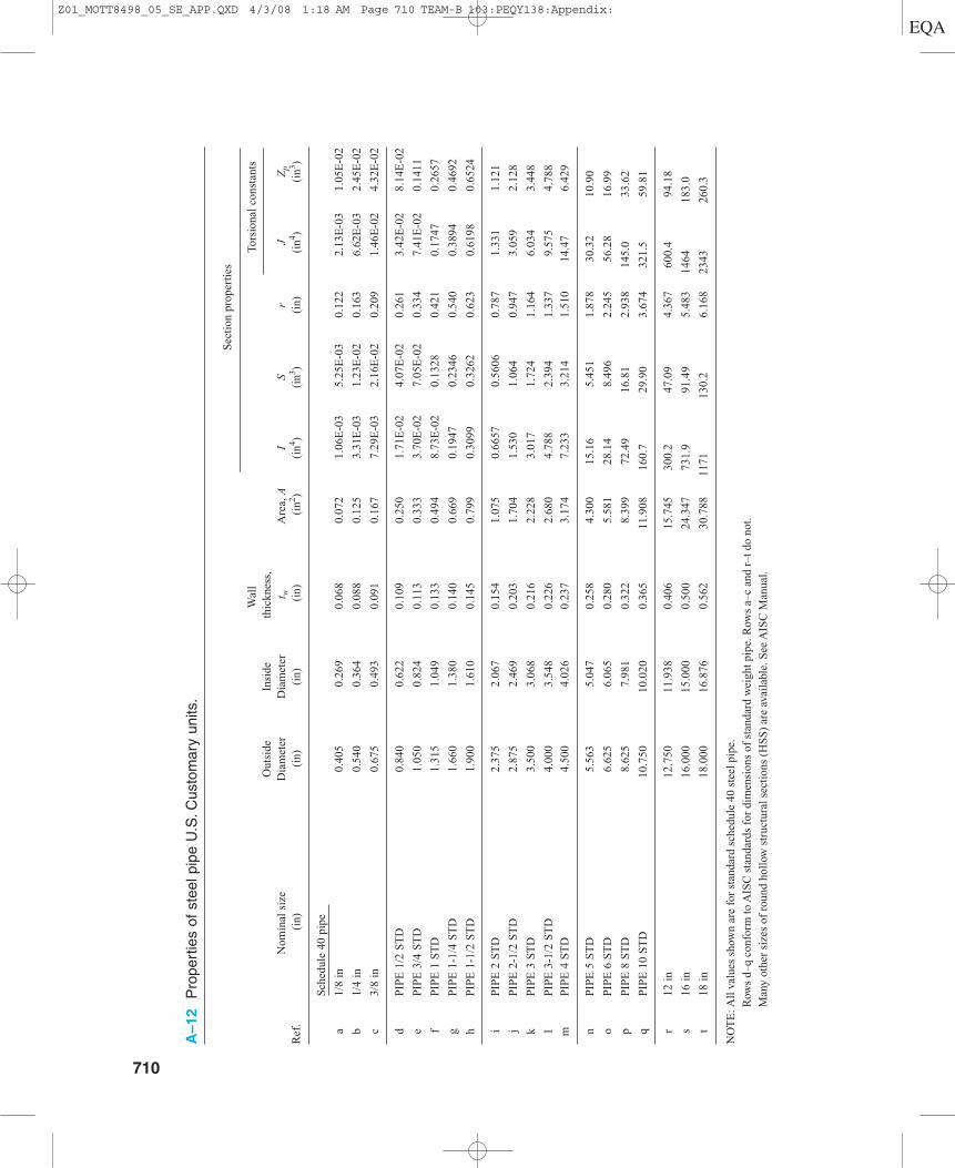
A–12
Pro
pert
ies
of s
teel
pip
e U
.S.C
usto
mar
y un
its.
Wal
l
Sec
tion
pro
pert
ies
Out
side
Insi
deth
ickn
ess,
Tors
iona
l co
nsta
nts
Nom
inal
siz
eD
iam
eter
Dia
met
ert w
Are
a, A
IS
rJ
Zp
Ref
.(i
n)
(in)
(in)
(in)
(in2 )
(in4 )
(in3 )
(in)
(in4 )
(in3 )
Sch
edul
e 40
pip
e
a1/
8 in
0.40
50.
269
0.06
80.
072
1.06
E-0
35.
25E
-03
0.12
22.
13E
-03
1.05
E-0
2
b1/
4 in
0.54
00.
364
0.08
80.
125
3.31
E-0
31.
23E
-02
0.16
36.
62E
-03
2.45
E-0
2
c3/
8 in
0.67
50.
493
0.09
10.
167
7.29
E-0
32.
16E
-02
0.20
91.
46E
-02
4.32
E-0
2
dP
IPE
1/2
ST
D0.
840
0.62
20.
109
0.25
01.
71E
-02
4.07
E-0
20.
261
3.42
E-0
28.
14E
-02
eP
IPE
3/4
ST
D1.
050
0.82
40.
113
0.33
33.
70E
-02
7.05
E-0
20.
334
7.41
E-0
20.
1411
fP
IPE
1 S
TD
1.31
51.
049
0.13
30.
494
8.73
E-0
20.
1328
0.42
10.
1747
0.26
57
gP
IPE
1-1
/4 S
TD
1.66
01.
380
0.14
00.
669
0.19
470.
2346
0.54
00.
3894
0.46
92
hP
IPE
1-1
/2 S
TD
1.90
01.
610
0.14
50.
799
0.30
990.
3262
0.62
30.
6198
0.65
24
iP
IPE
2 S
TD
2.37
52.
067
0.15
41.
075
0.66
570.
5606
0.78
71.
331
1.12
1
jP
IPE
2-1
/2 S
TD
2.87
52.
469
0.20
31.
704
1.53
01.
064
0.94
73.
059
2.12
8
kP
IPE
3 S
TD
3.50
03.
068
0.21
62.
228
3.01
71.
724
1.16
46.
034
3.44
8
lP
IPE
3-1
/2 S
TD
4.00
03.
548
0.22
62.
680
4.78
82.
394
1.33
79.
575
4.78
8
mP
IPE
4 S
TD
4.50
04.
026
0.23
73.
174
7.23
33.
214
1.51
014
.47
6.42
9
nP
IPE
5 S
TD
5.56
35.
047
0.25
84.
300
15.1
65.
451
1.87
830
.32
10.9
0
oP
IPE
6 S
TD
6.62
56.
065
0.28
05.
581
28.1
48.
496
2.24
556
.28
16.9
9
pP
IPE
8 S
TD
8.62
57.
981
0.32
28.
399
72.4
916
.81
2.93
814
5.0
33.6
2
qP
IPE
10
ST
D10
.750
10.0
200.
365
11.9
0816
0.7
29.9
03.
674
321.
559
.81
r12
in
12.7
5011
.938
0.40
615
.745
300.
247
.09
4.36
760
0.4
94.1
8
s16
in
16.0
0015
.000
0.50
024
.347
731.
991
.49
5.48
314
6418
3.0
t18
in
18.0
0016
.876
0.56
230
.788
1171
130.
26.
168
2343
260.
3
NO
TE
:All
val
ues
show
n ar
e fo
r st
anda
rd s
ched
ule
40 s
teel
pip
e.
Row
s d–
q co
nfor
m to
AIS
C s
tand
ards
for
dim
ensi
ons
of s
tand
ard
wei
ght p
ipe.
Row
s a–
c an
d r–
t do
not.
Man
y ot
her
size
s of
rou
nd h
ollo
w s
truc
tura
l sec
tion
s (H
SS
) ar
e av
aila
ble.
See
AIS
C M
anua
l.
710
Z01_MOTT8498_05_SE_APP.QXD 4/3/08 1:18 AM Page 710 TEAM-B 103:PEQY138:Appendix:
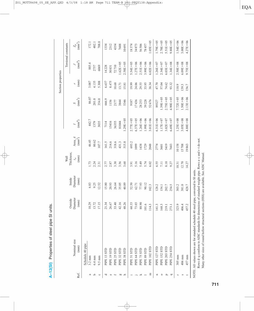
A–12(S
I)P
rope
rtie
s of
ste
el p
ipe
SI
units
.
Wal
l
Sec
tion
pro
pert
ies
Out
side
Insi
deT
hick
ness
,To
rsio
nal
cons
tant
s
Nom
inal
siz
eD
iam
eter
Dia
met
ert w
Are
a, A
IS
rJ
Zp
Ref
.(m
m)
(mm
)(m
m)
(mm
)(m
m2 )
(mm
4 )(m
m3 )
(mm
)(m
m4 )
(mm
3 )
Sch
edul
e 40
pip
e
a3.
2 m
m10
.29
6.83
1.73
46.4
544
2.7
86.0
73.
087
885.
417
2.1
b6.
4 m
m13
.72
9.25
2.24
80.6
213
7920
1.0
4.13
527
5740
2.1
c9.
5 m
m17
.15
12.5
22.
3110
7.7
3035
354.
05.
308
6069
708.
0
dP
IPE
13
ST
D21
.34
15.8
02.
7716
1.5
7114
666.
96.
637
1422
813
34
eP
IPE
19
ST
D26
.67
20.9
32.
8721
4.6
1541
611
568.
475
3083
123
12
fP
IPE
25
ST
D33
.40
26.6
43.
3831
8.6
3635
521
7710
.68
7271
043
54
gP
IPE
32
ST
D42
.16
35.0
53.
5643
1.3
8104
438
4413
.71
1.62
E�
0576
88
hP
IPE
38
ST
D48
.26
40.8
93.
6851
5.8
1.29
E�
0553
4615
.81
2.58
E�
0510
691
i P
IPE
51
ST
D60
.33
52.5
03.
9169
3.2
2.77
E�
0591
8719
.99
5.54
E�
0518
374
jP
IPE
64
ST
D73
.03
62.7
15.
1610
996.
37E
�05
1743
624
.06
1.27
E�
0634
873
kP
IPE
75
ST
D88
.90
77.9
35.
4914
381.
26E
�06
2825
329
.55
2.51
E�
0656
506
lP
IPE
89
ST
D10
1.6
90.1
25.
7417
291.
99E
�06
3922
833
.95
3.99
E�
0678
457
mP
IPE
102
ST
D11
4.3
102.
36.
0220
483.
01E
�06
5267
638
.34
6.02
E�
061.
05E
�05
nP
IPE
127
ST
D14
1.3
128.
26.
5527
746.
31E
�06
8932
747
.70
1.26
E�
071.
79E
�05
oP
IPE
152
ST
D16
8.3
154.
17.
1136
011.
17E
�07
1.39
E�
0557
.04
2.34
E�
072.
78E
�05
pP
IPE
203
ST
D21
9.1
202.
78.
1854
193.
02E
�07
2.75
E�
0574
.62
6.03
E�
075.
51E
�05
qP
IPE
254
ST
D27
3.1
254.
59.
2776
836.
69E
�07
4.90
E�
0593
.32
1.34
E�
089.
80E
�05
r30
5 m
m32
3.9
303.
210
.31
1015
81.
25E
�08
7.72
E�
0511
0.9
2.50
E�
081.
54E
�06
s 40
6 m
m40
6.4
381.
012
.70
1570
83.
05E
�08
1.50
E�
0613
9.3
6.09
E�
083.
00E
�06
t45
7 m
m45
7.2
428.
714
.27
1986
34.
88E
�08
2.13
E�
0615
6.7
9.75
E�
084.
27E
�06
NO
TE
:All
val
ues
show
n ar
e fo
r st
anda
rd s
ched
ule
40 s
teel
pip
e, c
onve
rted
to S
I un
its.
Row
s d–
q co
nfor
m to
AIS
C s
tand
ards
for
dim
ensi
ons
of s
tand
ard
wei
ght p
ipe.
Row
s a–
c an
d r–
t do
not.
Man
y ot
her
size
s of
rou
nd h
ollo
w s
truc
tura
l sec
tion
s (H
SS
) ar
e av
aila
ble.
See
AIS
C M
anua
l.
711
Z01_MOTT8498_05_SE_APP.QXD 4/3/08 1:18 AM Page 711 TEAM-B 103:PEQY138:Appendix:
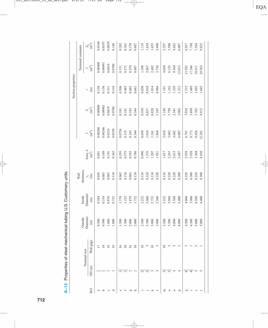
A–13
Pro
pert
ies
of s
teel
mec
hani
cal t
ubin
g U
.S.C
usto
mar
y un
its.
Wal
l
Sec
tion
pro
pert
ies
Out
side
Insi
deth
ickn
ess,
Tors
iona
l co
nsta
nts
Nom
inal
siz
eD
iam
eter
Dia
met
ert w
Are
a, A
IS
rJ
Zp
Ref
.O
D (
in)
Wal
l ga
ge(i
n)(i
n)(i
n)(i
n2 )(i
n4 )(i
n3 )(i
n)(i
n4 )(i
n3 )
a17
0.50
00.
384
0.05
80.
081
0.00
200
0.00
800
0.15
80.
0040
00.
0160
b14
0.50
00.
334
0.08
30.
109
0.00
246
0.00
983
0.15
00.
0049
10.
0197
c1
161.
000
0.87
00.
065
0.19
10.
0210
0.04
190.
331
0.04
190.
0839
d1
101.
000
0.73
20.
134
0.36
50.
0350
0.07
000.
310
0.07
000.
140
e1
161.
500
1.37
00.
065
0.29
30.
0756
0.10
10.
508
0.15
10.
202
f1
101.
500
1.23
20.
134
0.57
50.
135
0.18
10.
485
0.27
10.
361
g2
162.
000
1.87
00.
065
0.39
50.
185
0.18
50.
685
0.37
00.
370
h2
102.
000
1.73
20.
134
0.78
60.
344
0.34
40.
661
0.68
70.
687
i2
102.
500
2.23
20.
134
0.99
60.
699
0.55
90.
838
1.39
81.
119
j2
52.
500
2.06
00.
220
1.57
61.
034
0.82
70.
810
2.06
71.
654
k3
103.
000
2.73
20.
134
1.20
71.
241
0.82
81.
014
2.48
31.
655
l3
53.
000
2.56
00.
220
1.92
11.
868
1.24
50.
986
3.73
62.
490
m3
103.
500
3.23
20.
134
1.41
72.
010
1.14
91.
191
4.02
02.
297
n3
53.
500
3.06
00.
220
2.26
73.
062
1.75
01.
162
6.12
53.
500
o4
54.
000
3.56
00.
220
2.61
34.
682
2.34
11.
339
9.36
44.
682
p4
14.
000
3.40
00.
300
3.48
76.
007
3.00
31.
312
12.0
136.
007
q4
54.
500
4.06
00.
220
2.95
86.
791
3.01
81.
515
13.5
836.
037
r4
14.
500
3.90
00.
300
3.95
88.
773
3.89
91.
489
17.5
467.
798
s5
55.
000
4.56
00.
220
3.30
49.
456
3.78
21.
692
18.9
117.
564
t5
15.
000
4.40
00.
300
4.43
012
.281
4.91
21.
665
24.5
629.
825
1 21 21 21 21 21 21 21 21 21 2
712
Z01_MOTT8490_05_SE_APP.QXD 6/8/10 7:01 PM Page 712
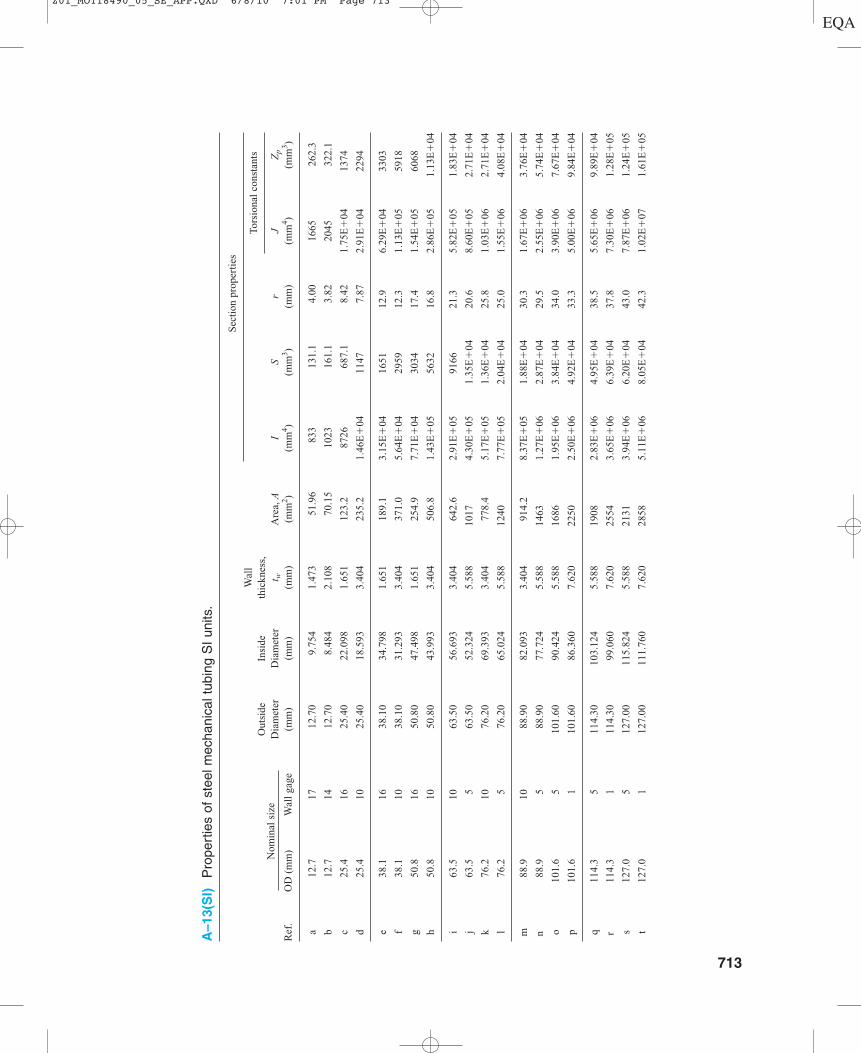
A–13(S
I)P
rope
rtie
s of
ste
el m
echa
nica
l tub
ing
SI
units
.
Wal
l
Sec
tion
pro
pert
ies
Out
side
Insi
deth
ickn
ess,
Tors
iona
l co
nsta
nts
Nom
inal
siz
eD
iam
eter
Dia
met
ert w
Are
a, A
IS
rJ
Zp
Ref
.O
D (
mm
) W
all
gage
(mm
)(m
m)
(mm
)(m
m2 )
(mm
4 )(m
m3 )
(mm
)(m
m4 )
(mm
3 )
a12
.717
12.7
09.
754
1.47
351
.96
833
131.
14.
0016
6526
2.3
b12
.714
12.7
08.
484
2.10
870
.15
1023
161.
13.
8220
4532
2.1
c25
.416
25.4
022
.098
1.65
112
3.2
8726
687.
18.
421.
75E
�04
1374
d25
.410
25.4
018
.593
3.40
423
5.2
1.46
E�
0411
477.
872.
91E
�04
2294
e38
.116
38.1
034
.798
1.65
118
9.1
3.15
E�
0416
5112
.96.
29E
�04
3303
f38
.110
38.1
031
.293
3.40
437
1.0
5.64
E�
0429
5912
.31.
13E
�05
5918
g50
.816
50.8
047
.498
1.65
125
4.9
7.71
E�
0430
3417
.41.
54E
�05
6068
h50
.810
50.8
043
.993
3.40
450
6.8
1.43
E�
0556
3216
.82.
86E
�05
1.13
E�
04
i63
.510
63.5
056
.693
3.40
464
2.6
2.91
E�
0591
6621
.35.
82E
�05
1.83
E�
04
j63
.55
63.5
052
.324
5.58
810
174.
30E
�05
1.35
E�
0420
.68.
60E
�05
2.71
E�
04
k76
.210
76.2
069
.393
3.40
477
8.4
5.17
E�
051.
36E
�04
25.8
1.03
E�
062.
71E
�04
l76
.25
76.2
065
.024
5.58
812
407.
77E
�05
2.04
E�
0425
.01.
55E
�06
4.08
E�
04
m88
.910
88.9
082
.093
3.40
491
4.2
8.37
E�
051.
88E
�04
30.3
1.67
E�
063.
76E
�04
n 88
.95
88.9
077
.724
5.58
814
631.
27E
�06
2.87
E�
0429
.52.
55E
�06
5.74
E�
04
o10
1.6
510
1.60
90.4
245.
588
1686
1.95
E�
063.
84E
�04
34.0
3.90
E�
067.
67E
�04
p10
1.6
110
1.60
86.3
607.
620
2250
2.50
E�
064.
92E
�04
33.3
5.00
E�
069.
84E
�04
q11
4.3
511
4.30
103.
124
5.58
819
082.
83E
�06
4.95
E�
0438
.55.
65E
�06
9.89
E�
04
r 11
4.3
111
4.30
99.0
607.
620
2554
3.65
E�
066.
39E
�04
37.8
7.30
E�
061.
28E
�05
s12
7.0
512
7.00
115.
824
5.58
821
313.
94E
�06
6.20
E�
0443
.07.
87E
�06
1.24
E�
05
t12
7.0
112
7.00
111.
760
7.62
028
585.
11E
�06
8.05
E�
0442
.31.
02E
�07
1.61
E�
05
713
Z01_MOTT8490_05_SE_APP.QXD 6/8/10 7:01 PM Page 713

36
PercentelongationMPaksiksi
MaterialAISI no. MPa
Ultimatestrength, su
A–14 Typical properties of carbon and alloy steels.*
Yieldstrength, sy
Condition†
36203025161922243225121317232614
152028261215182317
121723
9
9
1020102010201040104010401040104010401040108010801080108010801141114111411141114111414140414041404140414051605160516051605160
576575759097
127118107
8789
189179145117
87112193146116
9495
231187147118105263196149115
393448517517621669876814738600614
130312341000
807600772
13311007
800648655
159312891014
814724
181313511027
793
4348645160829390806354
141129103
705195
172129
976860
212173131101
40238179132103
296331441352414565641621552434372972889710483352655
1186889669469414
14621193
903696276
16411234
910710
AnnealedHot-rolled
Cold-drawnAnnealedHot-rolled
Cold-drawnWQT 700WQT 900
WQT 1100WQT 1300AnnealedOQT 700OQT 900
OQT 1100OQT 1300
OQT 700OQT 900
OQT 1100OQT 1300
OQT 700OQT 900
OQT 1100OQT 1300
AnnealedCold-drawn
Annealed
OQT 700OQT 900
OQT 1100OQT 1300
Annealed
*Other properties approximately the same for all carbon and alloy steels: Modulus of elasticity in tension = 30 000 000 psi (207 GPa) Modulus of elasticity in shear = 11 500 000 psi (80 GPa) Density = 0.283 lbm/in3 (7680 kg/m3)†OQT means oil-quenched and tempered. WQT means water-quenched and tempered.
714 Appendix
Untitled-1.indd 5 05/02/15 6:37 PM
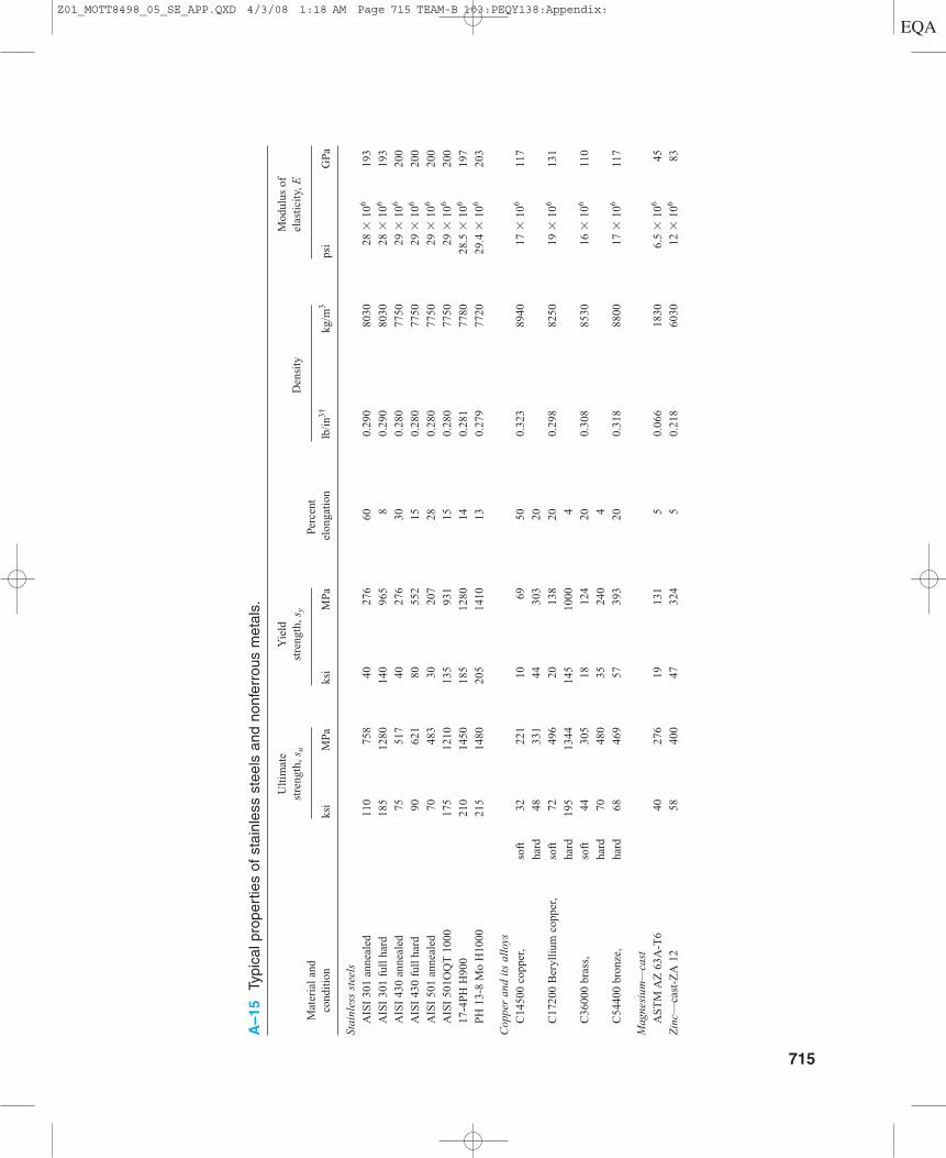
A–15
Typi
cal p
rope
rtie
s of
sta
inle
ss s
teel
s an
d no
nfer
rous
met
als.
Ult
imat
eY
ield
M
odul
us o
f st
reng
th, s
ust
reng
th, s
yD
ensi
tyel
asti
city
, EM
ater
ial
and
Perc
ent
cond
itio
nks
iM
Paks
iM
Pael
onga
tion
lb/i
n3†kg
/m3
psi
GPa
Stai
nles
s st
eels
AIS
I 30
1 an
neal
ed11
075
840
276
600.
290
8030
28 �
106
193
AIS
I 30
1 fu
ll h
ard
185
1280
140
965
80.
290
8030
28 �
106
193
AIS
I 43
0 an
neal
ed75
517
4027
630
0.28
077
5029
�10
620
0
AIS
I 43
0 fu
ll h
ard
9062
180
552
150.
280
7750
29 �
106
200
AIS
I 50
1 an
neal
ed70
48
330
207
280.
280
7750
29 �
106
200
AIS
I 50
1OQ
T 1
000
175
1210
135
931
150.
280
7750
29 �
106
200
17-4
PH
H90
021
014
5018
512
8014
0.28
177
8028
.5 �
106
197
PH
13-
8 M
o H
1000
215
1480
205
1410
130.
279
7720
29.4
�10
620
3
Cop
per
and
its
allo
ys
C14
500
copp
er,
soft
3222
110
6950
0.32
389
4017
�10
611
7
hard
4833
144
303
20
C17
200
Ber
ylli
um c
oppe
r,so
ft72
496
2013
820
0.29
882
5019
�10
613
1
hard
195
1344
145
1000
4
C36
000
bras
s,
soft
4430
518
124
200.
308
8530
16 �
106
110
hard
7048
035
240
4
C54
400
bron
ze,
hard
6846
957
393
200.
318
8800
17 �
106
117
Mag
nesi
um—
cast
AS
TM
AZ
63A
-T6
4027
619
131
50.
066
1830
6.5
�10
645
Zin
c—ca
st-Z
A 1
258
400
4732
45
0.21
860
3012
�10
683
715
Z01_MOTT8498_05_SE_APP.QXD 4/3/08 1:18 AM Page 715 TEAM-B 103:PEQY138:Appendix:
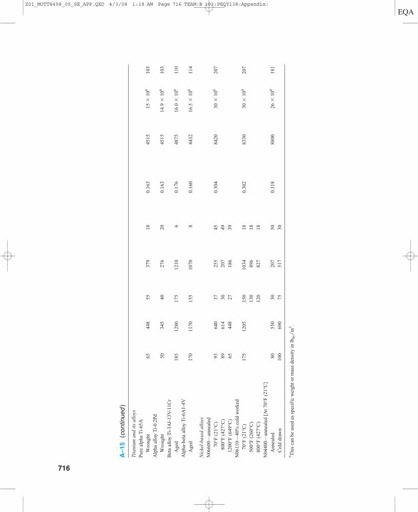
Tita
nium
and
its
all
oys
Pur
e al
pha
Ti-
65A
Wro
ught
6544
855
379
180.
163
4515
15 �
106
103
Alp
ha a
lloy
Ti-
0.2P
d
Wro
ught
5034
540
276
200.
163
4515
14.9
�10
610
3
Bet
a al
loy
Ti-
3Al-
13V
-11C
r
Age
d18
512
8017
512
106
0.17
648
7516
.0 �
106
110
Alp
ha-b
eta
allo
y T
i-6A
1-4V
Age
d17
011
7015
510
708
0.16
044
3216
.5 �
106
114
Nic
kel-
base
d al
loys
N06
600—
anne
aled
70°F
(21
°C)
9364
037
255
450.
304
8420
30 �
106
207
800°
F (
427°
C)
8961
430
207
49
1200
°F (
649°
C)
6544
827
186
39
N06
110—
40%
col
d w
orke
d
70°F
(21
°C)
175
1205
150
1034
180.
302
8330
30 �
106
207
500°
F (
260°
C)
130
896
18
800°
F (
427°
C)
120
827
18
N04
400—
anne
aled
[A
t 70
°F (
21°C
]
Ann
eale
d80
550
3020
750
0.31
888
0026
�10
618
1
Col
d dr
awn
100
690
7551
730
† Thi
s ca
n be
use
d as
spe
cifi
c w
eigh
t or
mas
s de
nsit
y in
lbm
in3 .
�
A–15
(con
tinue
d)
716
Z01_MOTT8498_05_SE_APP.QXD 4/3/08 1:18 AM Page 716 TEAM-B 103:PEQY138:Appendix:
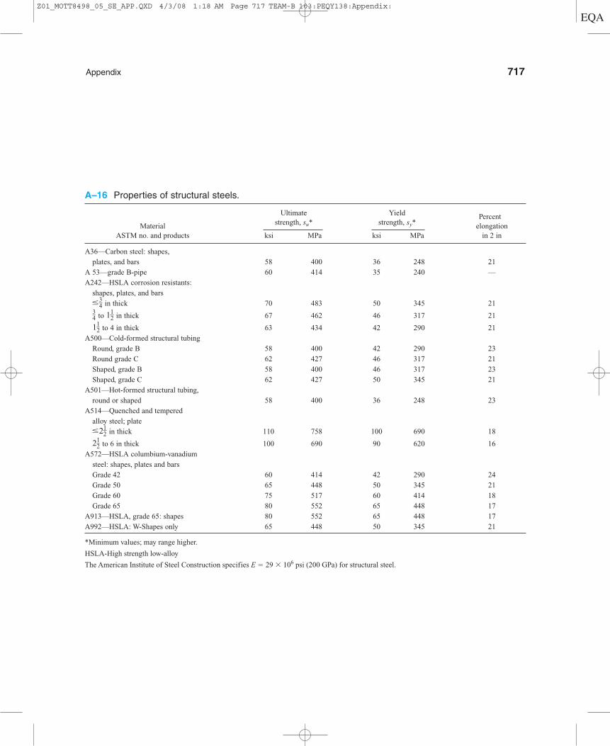
Appendix 717
A–16 Properties of structural steels.
Ultimate Yield strength, su* strength, sy*
PercentMaterial elongation
ASTM no. and products ksi MPa ksi MPa in 2 in
A36—Carbon steel: shapes,
plates, and bars 58 400 36 248 21
A 53—grade B-pipe 60 414 35 240 —
A242—HSLA corrosion resistants:
shapes, plates, and bars
in thick 70 483 50 345 21
to in thick 67 462 46 317 21
to 4 in thick 63 434 42 290 21
A500—Cold-formed structural tubing
Round, grade B 58 400 42 290 23
Round grade C 62 427 46 317 21
Shaped, grade B 58 400 46 317 23
Shaped, grade C 62 427 50 345 21
A501—Hot-formed structural tubing,
round or shaped 58 400 36 248 23
A514—Quenched and tempered
alloy steel; plate
in thick 110 758 100 690 18
to 6 in thick 100 690 90 620 16
A572—HSLA columbium-vanadium
steel: shapes, plates and bars
Grade 42 60 414 42 290 24
Grade 50 65 448 50 345 21
Grade 60 75 517 60 414 18
Grade 65 80 552 65 448 17
A913—HSLA, grade 65: shapes 80 552 65 448 17
A992—HSLA: W-Shapes only 65 448 50 345 21
*Minimum values; may range higher.
HSLA-High strength low-alloy
The American Institute of Steel Construction specifies E � 29 � 106 psi (200 GPa) for structural steel.
212
…212
112
112
34
…34
Z01_MOTT8498_05_SE_APP.QXD 4/3/08 1:18 AM Page 717 TEAM-B 103:PEQY138:Appendix:
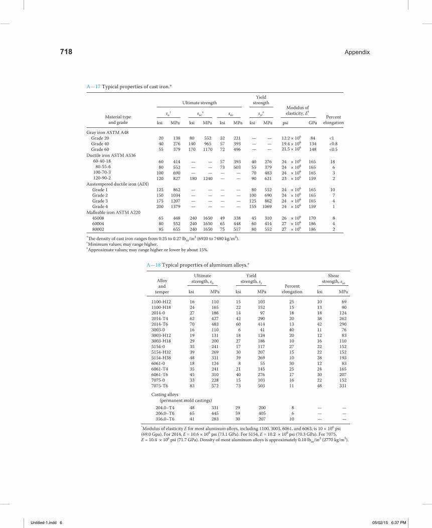
Material typeand grade
Ultimate strength
A—17 Typical properties of cast iron.*
A—18 Typical properties of aluminum alloys.*
Yieldstrength
PercentelongationGPaMPa psiksiMPaksiMPaksiMPaksi
Modulus ofelasticity, E‡syt‡suc‡su† sus
Gray iron ASTM A48Grade 20Grade 40Grade 60
204055
80140170
84134148
<1<0.8<0.5
552965
1170
325772
221393496
———
———
180
———
1240
———
12.2 × 10⁶
19.4 × 10⁶
21.5 × 10⁶
24 × 106
24 × 106
24 × 106
23 × 106
138276379
Ductile iron ASTM A53660-40-18
80-55-6100-70-3120-90-2
6080
100120
414552690827
393503
——
40557090
276379483621
165165165159
18632
5773——
————
————
24 × 106
24 × 106
24 × 106
24 × 106
Austempered ductile iron (ADI)Grade 1Grade 2Grade 3Grade 4
125150175200
862103412071379
————
80100125155
552690862
1069
165165165159
10741
————
240240240
165016501650
26 × 106
27 × 106
27 × 106
Malleable iron ASTM A220450086000480002
*�e density of cast iron ranges from 0.25 to 0.27 lbm/in3 (6920 to 7480 kg/m3).†Minimum values; may range higher.‡Approximate values; may range higher or lower by about 15%.
658095
448552655
338448517
456080
310414552
170186186
842
496575
Alloyand
temper
Ultimatestrength, su
Yieldstrength, sy
Shearstrength, sus
MPaksiPercent
elongationMPaksiMPaksi
*Modulus of elasticity E for most aluminum alloys, including 1100, 3003, 6061, and 6063, is 10 × 106 psi(69.0 Gpa). For 2014, E = 10.6 × 10⁶ psi (73.1 GPa). For 5154, E = 10.2 × 10⁶ psi (70.3 GPa). For 7075,E = 10.4 × 10⁶ psi (71.7 GPa). Density of most aluminum alloys is approximately 0.10 lbm/in3 (2770 kg/m3).
(permanent mold castings)Casting alloys
1100-H121100-H182014-02014-T42014-T63003-03003-H123003-H185154-05154-H325154-H386061-06061-T46061-T67075-07075-T6
16242762701619293539481835453383
110165186427483110131200241269331124241310228572
1522144260
61827173039
821401573
103152
97290414
41124186117207269
55145276103503
25151820134020102715103025171611
10131838421112162222281224302248
6990
124262290
7683
110152152193
83165207152331
204.0–T4206.0–T6356.0–T6
486541
331445283
295930
200405207
86
10
———
———
718 Appendix
Untitled-1.indd 6 05/02/15 6:37 PM
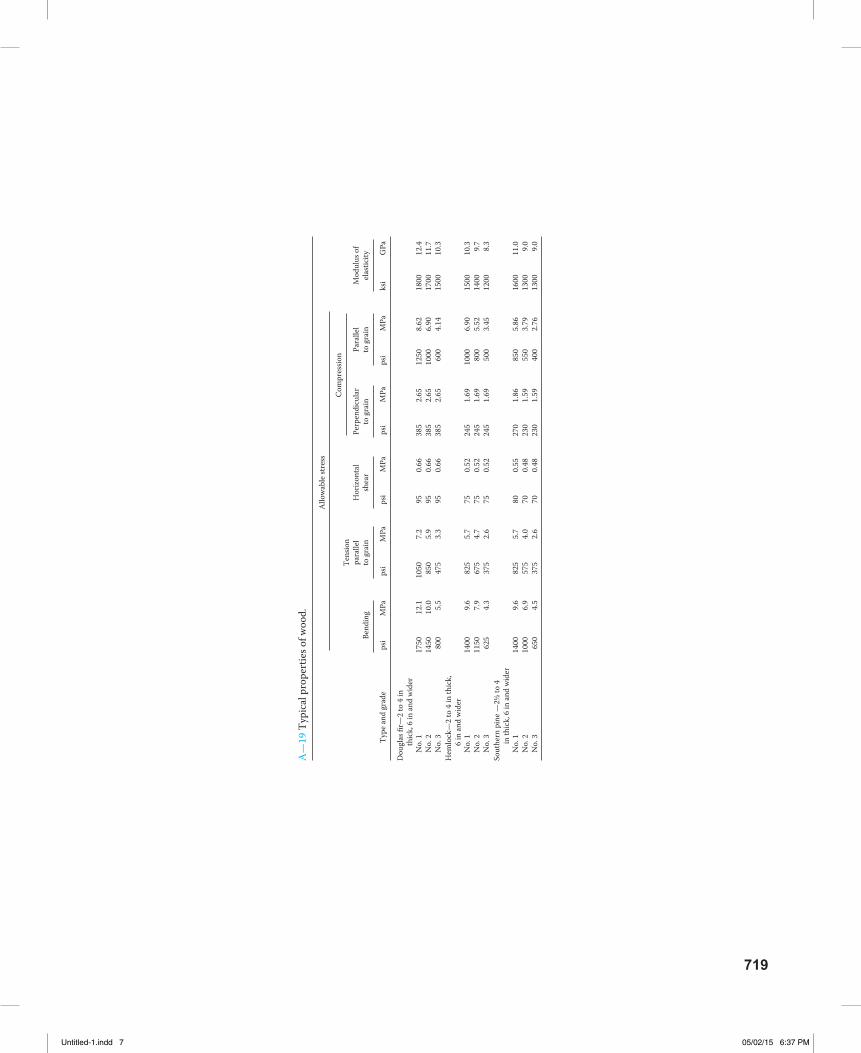
Allo
wab
le st
ress
A—
19 T
ypic
al p
rope
rtie
s of w
ood.
Bend
ing
psi
No.
1N
o. 2
No.
3
1750
1450 80
0
12.1
10.0 5.5
7.2
5.9
3.3
95 95 95
0.66
0.66
0.66
385
385
385
2.65
2.65
2.65
1250
1000 60
0
8.62
6.90
4.14
1800
1700
1500
12.4
11.7
10.3
1050 85
047
5
Type
and
grad
e
Dou
glas
fir—
2 to
4 in
thi
ck, 6
in an
d w
ider
No.
1N
o. 2
No.
3
1400
1150 62
5
9.6
7.9
4.3
5.7
4.7
2.6
75 75 75
0.52
0.52
0.52
245
245
245
1.69
1.69
1.69
1000 80
050
0
6.90
5.52
3.45
1500
1400
1200
10.3 9.7
8.3
825
675
375
Hem
lock
—2
to 4
in th
ick,
6 in
and
wid
er
No.
1N
o. 2
No.
3
1400
1000 65
0
9.6
6.9
4.5
5.7
4.0
2.6
80 70 70
0.55
0.48
0.48
270
230
230
1.86
1.59
1.59
850
550
400
5.86
3.79
2.76
1600
1300
1300
11.0 9.0
9.0
825
575
375
Sout
hern
pin
e —2½
to 4
in
thic
k, 6
in an
d w
ider
MPa
psi
MPa
psi
MPa
psi
MPa
psi
MPa
ksi
GPa
Tens
ion
para
llel
to g
rain
Hor
izon
tal
shea
rM
odul
us o
fel
astic
ityPa
ralle
lto
gra
in
Com
pres
sion
Perp
endi
cula
rto
gra
in
719
Untitled-1.indd 7 05/02/15 6:37 PM
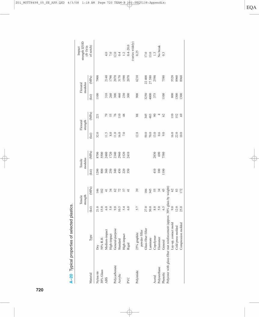
A–20
Typi
cal p
rope
rtie
s of
sel
ecte
d pl
astic
s. Tens
ile
Tens
ile
Fle
xura
l F
lexu
ral
Impa
ct
stre
ngth
mod
ulus
stre
ngth
mod
ulus
stre
ngth
IZ
OD
(f
t�1b
/in
Mat
eria
lTy
pe(k
si)
(MPa
)(k
si)
(MPa
)(k
si)
(MPa
)(k
si)
(MPa
)of
not
ch)
Nyl
on 6
6 D
ry21
.014
612
0087
0032
.022
111
0079
00
30%
Gla
ss50
% R
.H.
15.0
102
800
5500
AB
SM
ediu
m-i
mpa
ct6.
041
360
2480
11.5
7931
021
404.
0
Hig
h-im
pact
5.0
3425
017
208.
055
260
1790
7.0
Poly
carb
onat
eG
ener
al-p
urpo
se9.
062
340
2340
11.0
7630
020
7012
.0
Acr
ylic
Sta
ndar
d10
.572
430
2960
16.0
110
460
3170
0.4
Hig
h-im
pact
5.4
3722
015
207.
048
230
1590
1.2
PV
CR
igid
6.0
4135
024
1030
020
700.
4–20
.0
(var
ies
wid
ely)
Poly
imid
e25
% g
raph
ite
5.7
3912
.888
900
6210
0.25
pow
der
fill
er
Gla
ss-f
iber
fil
ler
27.0
186
50.0
345
3250
22 4
0017
.0
Lam
inat
e50
.034
570
.048
340
0027
580
13.0
Ace
tal
Cop
olym
er8.
055
410
2830
13.0
9037
525
901.
3
Poly
uret
hane
Ela
stom
er
5.0
3410
069
00.
64
No
brea
k
Phe
noli
c G
ener
al6.
545
1100
7580
9.0
6211
0075
800.
3
Poly
este
r w
ith
glas
s-fi
ber
mat
rei
nfor
cem
ent
(app
rox.
30%
gla
ss b
y w
eigh
t)
Lay
-up,
con
tact
mol
d9.
062
16.0
110
800
5520
Col
d pr
ess
mol
ded
12.0
8322
.015
213
0089
60
Com
pres
sion
mol
ded
25.0
172
10.0
6913
0089
60
720
Z01_MOTT8498_05_SE_APP.QXD 4/3/08 1:18 AM Page 720 TEAM-B 103:PEQY138:Appendix:

Appendix 721
A–21 Design stress guidelines.
Direct Normal Stresses—General machine and structural design
Manner of Ductile Materials Brittle Materials loading (% Elongation �5%) (% Elongation �5%)
Static loads sd � sy �2 sd � su�6Repeated loads sd � su�8 sd � su�10Impact or shock sd � su�12 sd � su�15
Direct Normal Stresses—Static loads on steel members of building-like structures
AISC Code: sd � sy �1.67 � 0.60 sy or sd � su�2.00 � 0.50 su
Whichever is lower.
Direct Normal Stresses—Static loads on aluminum members of building-like structures
Aluminum Association: sd � sy�1.65 � 0.61 sy or sd � su�1.95 � 0.51 su
Whichever is lower.
Design Shear Stresses—For direct shear and for torsional shear stresses
Based on maximum shear stress theory of failure:
td � sys�N � 0.5 sy�N � sy �2N
Manner of Design Design loading factor shear stress
Static loads Use N � 2 td � sy�4Repeated loads Use N � 4 td � sy �8Shock or impact Use N � 6 td � sy �12
Estimates for the Ultimate Strength in Shear
Formula Material
sus � 0.65 su Aluminum alloyssus � 0.82 su Steel—Plain carbon and alloysus � 0.90 su Malleable iron and copper alloyssus � 1.30 su Gray cast iron
Allowable Bearing StressSteel—Flat surfaces or the projected area of pins in reamed, drilled, or bored holes:
sbd � 0.90 sy
Allowable Bearing Load, Ra,—Steel roller on flat steel plateU.S. Customary Units SI Metric Units
Ra � (sy 13) (0.03 dL) Ra � (sy 90) (3.0 � 105dL)
Where: Ra � Allowable bearing load in kips or kNsy � Yield strength of steel in ksi or MPad � Roller diameter in inches or mmL � Length of roller in inches or mm
(continued)
Z01_MOTT8498_05_SE_APP.QXD 4/3/08 1:18 AM Page 721 TEAM-B 103:PEQY138:Appendix:
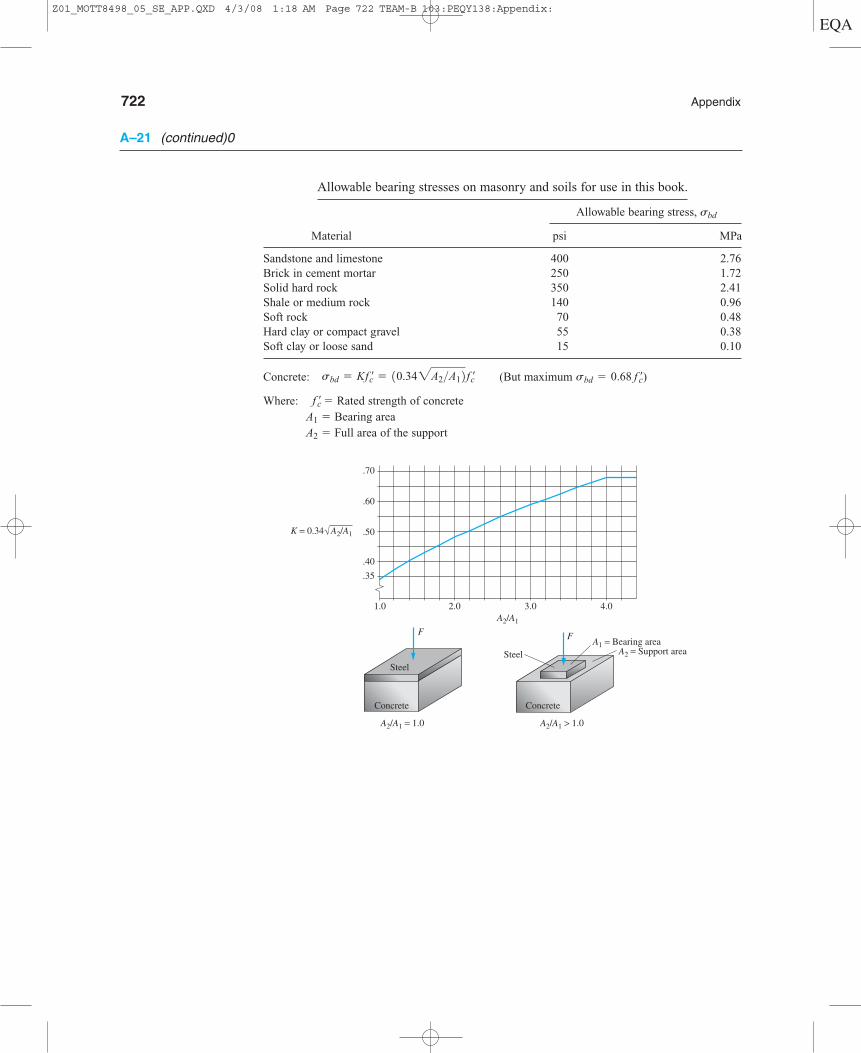
722 Appendix
.35
1.0 2.0 3.0 4.0
.40
.50
.60
.70
F F
SteelSteel
Concrete Concrete
A2/A1 = 1.0 A2/A1 > 1.0
K = 0.34
A2/A1
A2/A1
A1 = Bearing areaA2 = Support area
A–21 (continued)0
Allowable bearing stresses on masonry and soils for use in this book.
Allowable bearing stress, �bd
Material psi MPa
Sandstone and limestone 400 2.76Brick in cement mortar 250 1.72Solid hard rock 350 2.41Shale or medium rock 140 0.96Soft rock 70 0.48Hard clay or compact gravel 55 0.38Soft clay or loose sand 15 0.10
Concrete: (But maximum )
Where: � Rated strength of concreteA1 � Bearing areaA2 � Full area of the support
f ¿c
sbd = 0.68 f ¿csbd = Kf ¿c = 10.342A2>A12f ¿c
Z01_MOTT8498_05_SE_APP.QXD 4/3/08 1:18 AM Page 722 TEAM-B 103:PEQY138:Appendix:
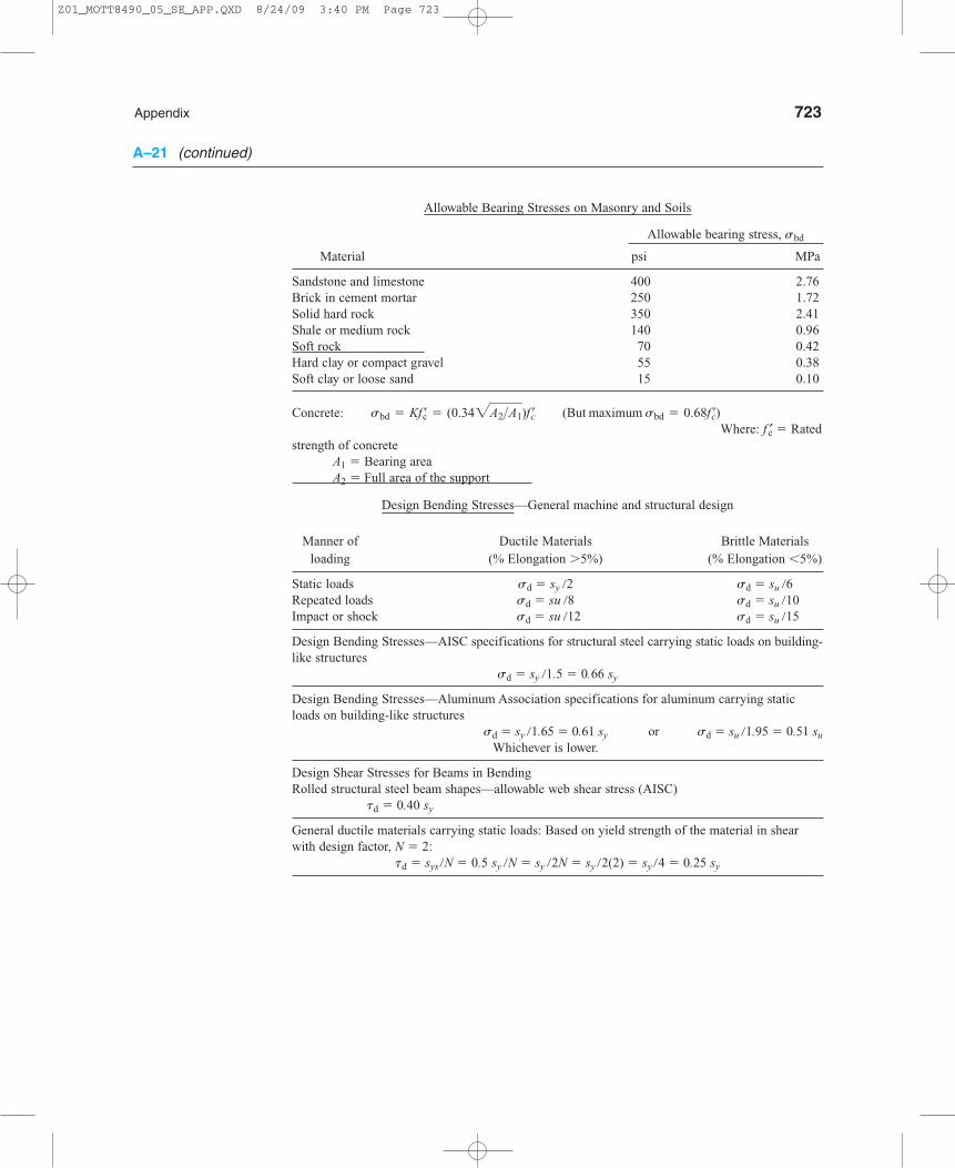
Appendix 723
Allowable Bearing Stresses on Masonry and Soils
Allowable bearing stress, sbd
Material psi MPa
Sandstone and limestone 400 2.76Brick in cement mortar 250 1.72Solid hard rock 350 2.41Shale or medium rock 140 0.96Soft rock 70 0.42Hard clay or compact gravel 55 0.38Soft clay or loose sand 15 0.10
Where: f ′c 5 Ratedstrength of concrete
A1 5 Bearing areaA2 5 Full area of the support
Design Bending Stresses—General machine and structural design
Manner of Ductile Materials Brittle Materials loading (% Elongation .5%) (% Elongation ,5%)
Static loads sd 5 sy /2 sd 5 su /6Repeated loads sd 5 su /8 sd 5 su /10Impact or shock sd 5 su /12 sd 5 su /15
Design Bending Stresses—AISC specifications for structural steel carrying static loads on building-like structures
sd 5 sy /1.5 5 0.66 sy
Design Bending Stresses—Aluminum Association specifications for aluminum carrying staticloads on building-like structures
sd 5 sy /1.65 5 0.61 sy or sd 5 su /1.95 5 0.51 su
Whichever is lower.
Design Shear Stresses for Beams in BendingRolled structural steel beam shapes—allowable web shear stress (AISC)
td 5 0.40 sy
General ductile materials carrying static loads: Based on yield strength of the material in shearwith design factor, N 5 2:
td 5 sys /N 5 0.5 sy /N 5 sy /2N 5 sy /2(2) 5 sy /4 5 0.25 sy
Concrete: sbd = Kf ¿c = (0.342A2>A1)f ¿c (But maximum sbd = 0.68f ¿c)
A–21 (continued)
Z01_MOTT8490_05_SE_APP.QXD 8/24/09 3:40 PM Page 723

724 Appendix
r = Groove radius
0 0.05 0.10 0.15 0.20 0.25
σmax = Kt σnom
σnom = F/(πd2g/4)
D/dg = 2.0
D/dg = 1.2
r/dg
2.5
2.4
2.3
2.2
2.1
2.0
1.9
1.8
1.7
1.6
1.5
1.4
1.3
1.2
1.1
1.0
Kt
D/dg = 1.1
D/dg = 1.05
DF Fdg
A–22 Stress Concentration Factors
A–22–1 Axially loaded grooved round bar in tension.
Z01_MOTT8498_05_SE_APP.QXD 4/4/08 3:19 AM Page 724 TEAM-B 103:PEQY138:Appendix:

Appendix 725
A–22–2 Axially loaded stepped round bar in tension.
0 0.05 0.10 0.15 0.20 0.25
r = Fillet radius
2.5
2.4
2.3
2.2
2.1
2.0
1.9
1.8
1.7
1.6
1.5
1.4
1.3
1.2
1.1
1.0
Kt
r/d
F d FD
σmax = Kt σnom
σnom = F/(πd2g/4)
D/d = 3.0
D/d = 2.0
D/d = 1.1D/d = 1.2
D/d = 1.05
Z01_MOTT8498_05_SE_APP.QXD 4/4/08 3:19 AM Page 725 TEAM-B 103:PEQY138:Appendix:

726 Appendix
A–22–3 Axially loaded stepped flat plate in tension.
σmax = Kt σnom
F
Kt
FH h
Thickness = t
r
σnom = = F Amin
Ft h
H/h = 2.0
1.2
3.4
1.00 0.04 0.08 0.12 0.16 0.20 0.24 0.28 0.32
1.4
1.8
2.2
2.6
3.0
1.1
1.01
r/h
Z01_MOTT8498_05_SE_APP.QXD 4/4/08 3:19 AM Page 726 TEAM-B 103:PEQY138:Appendix:

Appendix 727
A–22–4 Flat plate with central hole in tension and bending
d
F
F F = total load Note: Kt = 1.0 for d/w < 0.5
M M
w
σmax = Kt σnom
Thickness = t
Basic geometry
σnom based on
net sectionA B
C
0 0.1 0.2 0.3 0.4 0.5 0.6 0.7 0.8 0.9 1.0
5.0
4.0
3.0
2.0
1.0
Kt
Curve A
Direct tensionon plate
Tension loadapplied througha pin in the hole
Curve B
Bending inthe plane ofthe plate
Curve C
σnom = = F Anet
F(w – d)t
F(w – d)t
σnom = = F Anet
σnom = =Mc Inet
6Mw(w3 – d3)t
d/w
Z01_MOTT8498_05_SE_APP.QXD 4/4/08 3:19 AM Page 727 TEAM-B 103:PEQY138:Appendix:
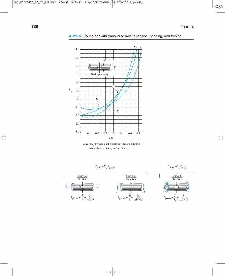
728 Appendix
A–22–5 Round bar with transverse hole in tension, bending, and torsion.
0
11.0
10.0
9.0
8.0
7.0
6.0Ktg
5.0
4.0
3.0
2.0
1.00.1
Note: Ktg is based on the nominal stress in a round
bar without a hole (gross section).
0.2 0.3
d/D
B A C
0.4
C
B
A
0.70.60.5
Basic geometry
D
d
Curve ATension
Curve BBending
Curve CTorsion
tmax=Ktg tgrossσmax=Ktg σgross
F F
M M T T
σgross = =F A
F πD2/4
σgross = =M S
M πD3/32
tgross = =T Zp
T πD3/16
Z01_MOTT8498_05_SE_APP.QXD 4/4/08 3:20 AM Page 728 TEAM-B 103:PEQY138:Appendix:
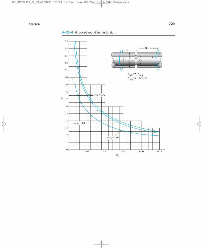
Appendix 729
A–22–6 Grooved round bar in torsion.
01.0
1.1
1.2
1.3
1.4
1.5
1.6
1.7
1.8
1.9
2.0
2.1
2.2
2.3
2.4
2.5
0.05 0.10 0.15 0.20 0.25
r/dg
Kt
D/dg = 1.2
D/dg = 2.0
D/dg = 1.05
r = Groove radius
tmax=Kt tnom
tnom=T/ (πdg3/16)
T
D dgT
Z01_MOTT8498_05_SE_APP.QXD 4/3/08 1:18 AM Page 729 TEAM-B 103:PEQY138:Appendix:

730 Appendix
A–22–7 Stepped round bar in torsion.
1.0
1.1
1.2
1.3
1.4
1.5
1.6
1.7
1.8
1.9
2.0
0 0.05 0.10 0.15 0.20 0.25
r/dg
Kt
= 1.25Dd
= 1.67Dd
= 1.11Dd
= 2.5Dd
r = Fillet radius
TD d
T
tmax=Kt tnom
tnom=T/ (πdg3/16)
Z01_MOTT8498_05_SE_APP.QXD 4/4/08 3:20 AM Page 730 TEAM-B 103:PEQY138:Appendix:

Appendix 731
A–22–8 Grooved round bar in bending.
r = Groove radius
MM
Ddg
smax = Kt snomsnom = M/(π d3
g /32)
D/dg = 2.0
D/dg = 1.2
D/dg = 1.05
0 0.05 0.10 0.15 0.20 0.25
r/dg
2.5
2.4
2.3
2.2
2.1
2.0
1.9
1.8
1.7
1.6
1.5
1.4
1.3
1.2
1.1
1.0
Kt
Z01_MOTT8498_05_SE_APP.QXD 4/3/08 1:18 AM Page 731 TEAM-B 103:PEQY138:Appendix:
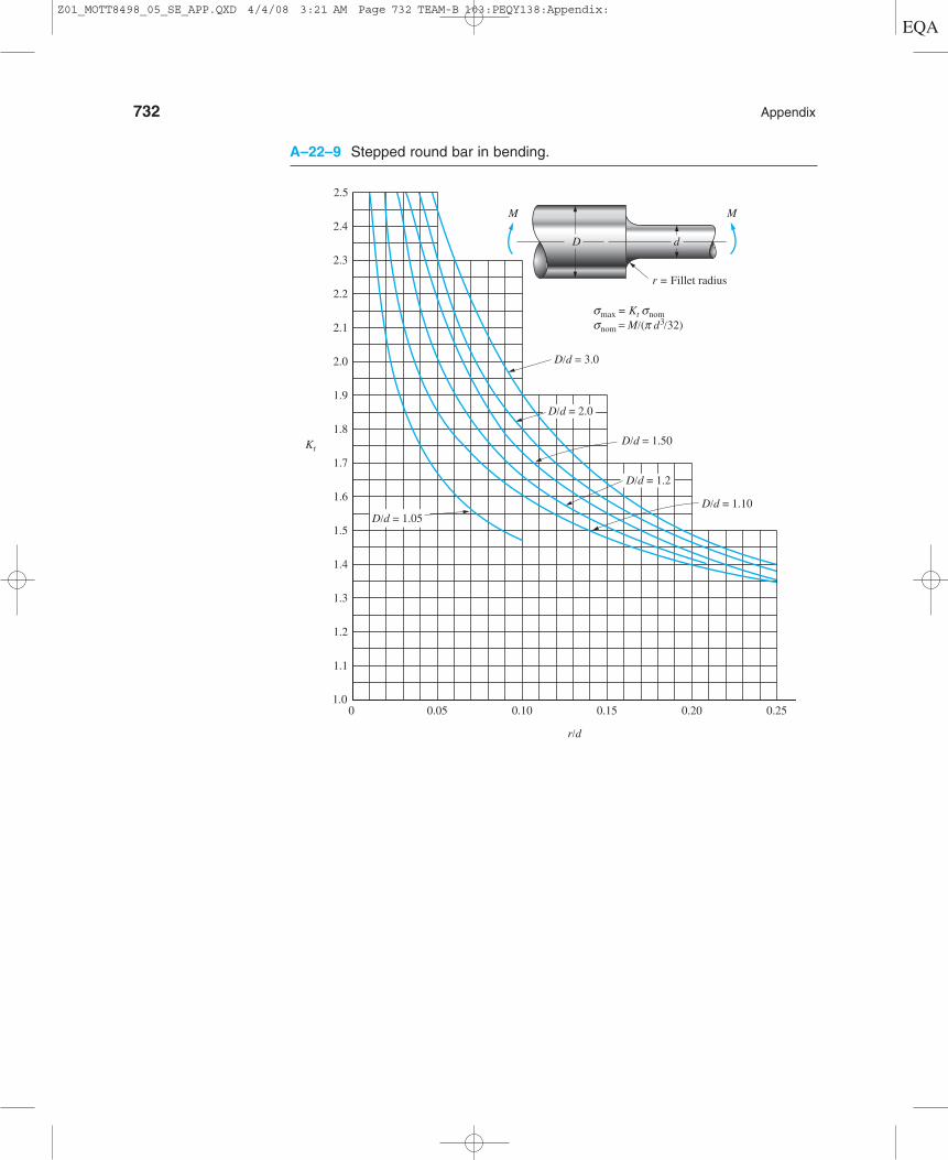
732 Appendix
A–22–9 Stepped round bar in bending.
0 0.05 0.10 0.15 0.20 0.25
d
r = Fillet radius
2.5
2.4
2.3
2.2
2.1
2.0
1.9
1.8
1.7
1.6
1.5
1.4
1.3
1.2
1.1
1.0
Kt
r/d
D
D/d = 3.0
D/d = 1.50
D/d = 1.10
M M
D/d = 2.0
D/d = 1.2
smax = Kt snomsnom = M/(p d3
/32)
D/d = 1.05
Z01_MOTT8498_05_SE_APP.QXD 4/4/08 3:21 AM Page 732 TEAM-B 103:PEQY138:Appendix:

Appendix 733
A–22–10 Stepped flat plate in bending.
smax = Kt snom
Kt
H h
Thickness = t
r
3.4
1.00 0.04 0.08 0.12 0.16
r/h
H/h = 2.0
1.2
1.05
0.20 0.24 0.28 0.32
1.4
1.8
2.2
2.6
3.0
MM
snom = =Smin t h2/6M M
1.01
A–22–11 Shafts with keyseats—bending and torsion.
Type of keyseat Kt*
Sled-runner 1.6Profile 2.0
*Kt is to be applied to the stress computed for
the full nominal diameter of the shaft where the
keyseat is located.
Z01_MOTT8490_05_SE_APP.QXD 8/24/09 3:42 PM Page 733
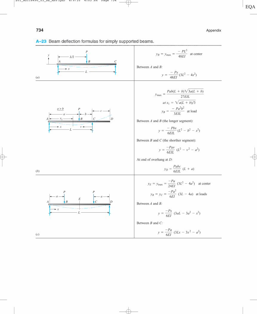
734 Appendix
L
a a
x
A B CE
D
P P
L
ax1
bc
x v
A B C D
Pa > b
L
L/2
x
y
A B C
P
Between A and B:
Between A and B (the longer segment):
Between B and C (the shorther segment):
At end of overhang at D:
Between A and B:
Between B and C:
y =
-Pa
6EI (3Lx - 3x
2- a2)
y =
-Px
6EI (3aL - 3a2
- x2)
yB = yC =
-Pa2
6EI (3L - 4a) at loads
yE = ymax =
-Pa
24EI (3L2
- 4a2) at center
yD =
Pabc
6EIL (L + a)
y =
-Pav
6EIL (L2
- v 2
- a2)
y =
- Pbx
6EIL (L2
- b2- x2)
yB =
- Pa2b2
3EIL at load
at x1 = 2a(L + b)�3
ymax =
Pab(L + b)23a(L + b)
27EIL
y =
- Px
48EI (3L2
- 4x2)
yB = ymax =
- PL3
48EI at center
(a)
(b)
(c)
Z01_MOTT8490_05_SE_APP.QXD 6/9/10 4:05 PM Page 734

L a
0.577L
B
RA
RB
P
A D Cx
L
a b
B
MB
A C
xy
Appendix 735
w = uniformilydistributed load
a
Lx
A B
C
L/2 a
Total load = W = wL
w = uniformily distributed load
Lx
A B C
D
A–23 (continued)
Between A and B:
At D at end:
Between A and B:
Between B and C:
Between A and B:
Between B and C:
At C at end of overhang:
At D, maximum upward deflection:
yD = 0.06415 PaL2
EI
yC =
- Pa2
3EI (L + a)
y =
MB
6EI c3a2
+ 3x 2
-
x 3
L- a2L +
3a2
L bx d
y =
-MB
6EI c a6a -
3a2
L- 2Lbx -
x3
Ld
MB = concentrated moment at B
y =
-wa2(L - x)
24EIL (4Lx - 2x
2- a
2)
y =
- wx
24EIL [a2(2L - a)2
- 2ax 2(2L - a) + Lx 3]
yD =
wL3a
24EI
y =
- wx
24EI (L3
- 2Lx 2
+ x 3)
yB = ymax =
-5wL4
384EI=
-5WL3
384EI at center
(d )
(e)
( f )
(g)
Z01_MOTT8498_05_SE_APP.QXD 4/3/08 1:18 AM Page 735 TEAM-B 103:PEQY138:Appendix:

aa
LL /2
B
P P
D
C EA
L a
0.577L
BA DC
w = uniformly distributed load
L
a aB
AD E
C
Total load = W = wL
w = uniformly distributed load
736 Appendix
A–23 (continued)
At C at center:
At A and E at ends:
At C at center:
At A and E at ends at loads:
At B:
At D at end:
y =
- wa3
24EI (4L + 3a)
y = 0.03208 wa2L2
EI
y =
- Pa2
3EI aa +
3
2Lb
y =
PL2a
8EI
y =
-W(L - 2a)3a
24EIL c - 1 + 6a
a
L - 2ab
2
+ 3aa
L - 2ab
3d
y =
-W(L - 2a)3
384EI c
5
L (L - 2a) -
24
L a
a2
L - 2ab d
(h)
(i)
( j)
Z01_MOTT8498_05_SE_APP.QXD 4/3/08 1:18 AM Page 736 TEAM-B 103:PEQY138:Appendix:

Appendix 737
L
a
A
x
CB
P
b
L
A
x
Bw � uniformly distributed load
L
A
x
B
MB
LA
y
x
B
P
At B at end:
Between A and B:
At B at load:
At C at end:
Between A and B:
Between B and C:
W � total load � wL
At B at end:
Between A and B:
MB � concentrated moment at end
At B at end:
Between A and B:
y =
-MB x 2
2EI
yB = ymax =
- MB L2
2EI
y =
-Wx2
24EIL [2L2
+ (2L - x)2]
yB = ymax =
-WL3
8EI
y =
- Pa2
6EI (3x - a)
y =
- Px 2
6EI (3a - x)
yC = ymax =
-Pa2
6EI (3L - a)
yB =
- Pa3
3EI
y =
- Px2
6EI (3L - x)
yB = ymax =
-PL3
3EI
(a)
(b)
(c)
(d )
Z01_MOTT8498_05_SE_APP.QXD 4/3/08 1:18 AM Page 737 TEAM-B 103:PEQY138:Appendix:
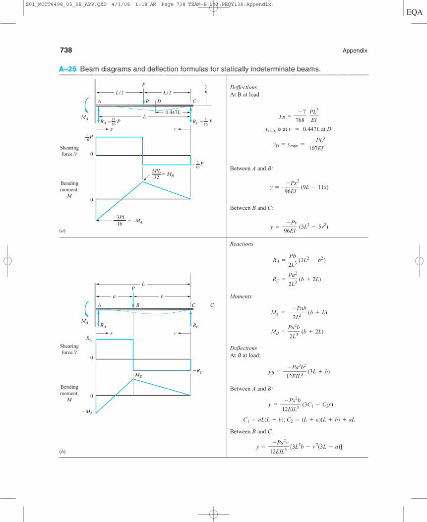
738 Appendix
A
vx
0
0
Shearingforce,V
Bendingmoment,
M
C
RA
RA
MA
MB �RC
RC
�MA
L
a
CB
Pb
L
L/2A B D
y
vx
0
0
Shearingforce,V
Bendingmoment,
M
C
P
P
PL/2
0.447L
RC � 516
516
P1116
5PL32
PRA � MA 11
16
� MB
–3PL16 � –MA
�
DeflectionsAt B at load:
Between A and B:
Between B and C:
Reactions
Moments
DeflectionsAt B at load:
Between A and B:
Between B and C:
y =
-Pa2v
12EIL3 [3L2b - v
2(3L - a)]
C1 = aL(L + b); C2 = (L + a)(L + b) + aL
y =
- Px2b
12EIL3 (3C1 - C2x)
yB =
- Pa3b2
12EIL3 (3L + b)
MB =
Pa2b
2L3 (b + 2L)
MA =
- Pab
2L2 (b + L)
RC =
Pa2
2L3 (b + 2L)
RA =
Pb
2L3 (3L2
- b2 )
y =
-Pv
96EI (3L2
- 5v2)
y =
-Px2
96EI (9L - 11x)
yD = ymax =
- PL3
107EI
ymax is at v = 0.447L at D:
yB =
- 7
768
PL3
EI
(a)
(b)
Z01_MOTT8498_05_SE_APP.QXD 4/3/08 1:18 AM Page 738 TEAM-B 103:PEQY138:Appendix:
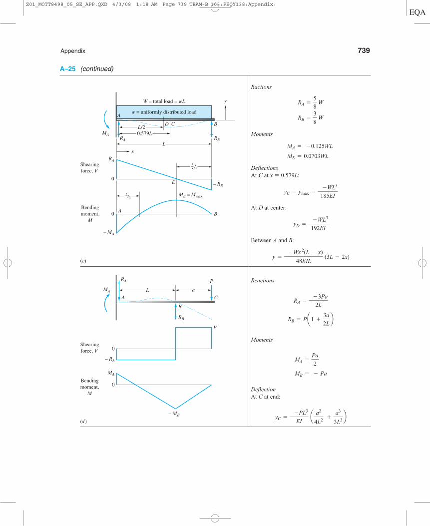
Appendix 739
A–25 (continued)
RB
B
P
MA
– RA
RA
L a
– MB
0
0
MA
A C
P
Shearingforce, V
Bendingmoment,
M
y
x
MA
RA
ME = Mmax
– MA
RA RB
A
D B
B
C
E
A
W = total load = wL
w = uniformly distributed load
L/2
L
0.579L
L38
0
0
Shearingforce, V
Bendingmoment,
M
– RB
L/4
Ractions
Moments
DeflectionsAt C at x � 0.579L:
At D at center:
Between A and B:
Reactions
Moments
DeflectionAt C at end:
yC =
-PL3
EI a
a2
4L2 +
a3
3L3b
MB = - Pa
MA =
Pa
2
RB = Pa1 +
3a
2Lb
RA =
- 3Pa
2L
y =
-Wx 2(L - x)
48EIL (3L - 2x)
yD =
- WL3
192EI
yC = ymax =
-WL3
185EI
ME = 0.0703WL
MA = - 0.125WL
RB =
3
8 W
RA =
5
8 W
(c)
(d )
Z01_MOTT8498_05_SE_APP.QXD 4/3/08 1:18 AM Page 739 TEAM-B 103:PEQY138:Appendix:
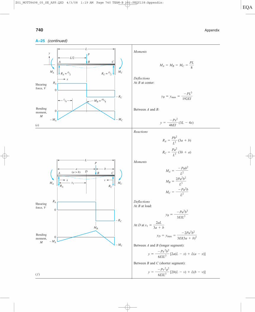
740 Appendix
MA MC
x v
a(a > b)
b
LP
BD CA
RA
x1RC
RA
MB
0
0– MA
– RC
– MC
Shearingforce, V
Bendingmoment,
M
y
0
0
MA MC
x
L/2
L
P
B CA
RA = P/2
MB = PL/8
RC = P/2
L/4
RA
– MA
– RC
– MC
Shearingforce, V
Bendingmoment,
M
A–25 (continued)
Moments
DeflectionsAt B at center:
Between A and B:
Reactions
Moments
DeflectionsAt B at load:
Between A and B (longer segment):
Between B and C (shorter segment):
y =
- Pv 2a2
6EIL3 [2b(L - v) + L(b - v)]
y =
- Px 2b2
6EIL3 [2a(L - x) + L(a - x)]
yD = ymax =
- 2Pa3b2
3EI(3a + b)2
At D at x1 =
2aL
3a + b
yB =
- Pa3b3
3EIL3
MC =
- Pa2b
L2
MB =
2Pa2b2
L3
MA =
- Pab2
L2
RC =
Pa2
L3 (3b + a)
RA =
Pb2
L3 (3a + b)
y =
- Px2
48EI (3L - 4x)
yB = ymax =
- PL3
192EI
MA = MB = MC =
PL
8
(e)
( f )
Z01_MOTT8498_05_SE_APP.QXD 4/3/08 1:19 AM Page 740 TEAM-B 103:PEQY138:Appendix:

y
Shearingforce, V
Bendingmoment,
M
MA MC
A
B C
W = total load = wL
w = uniformly distributed load
L/2x
RA = W/2 RC = W/2
L
0
0
RA
MB
– MA
– RC
– MC
Shearingforce, V
Bendingmoment,
M
RC
B CA
w = uniformly distributed load
L L
RA
x1 x1
RB
0
0
VA
VB
MD ME
A D
B
E C
– VC– VB
3L8
3L8
– MB
A–25 (continued)
Appendix 741
Moments
DeflectionsAt B at center:
Between A and C:
Reactions
Shearing forces
Moments
Deflections
At x1 � 0.4215L from A or C:
Between A and B:
y =
-w
48EI (L3x - 3Lx
3+ 2x4)
ymax =
- wL4
185EI
MB = - 0.125wL2
MD = ME = 0.0703wL2
VB =
5wL
8
VA = VC = RA = RC =
3wL
8
RB = 1.25wL
RA = RC =
3wL
8
y =
- wx 2
24EI (L - x)2
yB = ymax =
-WL3
384EI
MB =
WL
24
MA = MC =
-WL
12
(g)
(h)
Z01_MOTT8498_05_SE_APP.QXD 4/3/08 1:19 AM Page 741 TEAM-B 103:PEQY138:Appendix:

742 Appendix
+VA
+VB
+VC
+VD
RC RD RE
B C D EA
w = uniformly distributed load
L L L LRA RB
0.54L
0.39L
0.54L0
0
Shearingforce, V
Bendingmoment,
M
0.39L
– VB
MB
MC
MD
– VC – VD
– VE
MI
MHMG
MF
0.4L
0.4wL 0.5wL 0.6wL
–0.6wL –0.5wL –0.4wL
ME
MG
MF
– MB – MC
RC RD
B C DA
w = uniformly distributed load
L L LRA RB
y
0.4L0.5LShearingforce, V
Bendingmoment,
M
0
0E G F
A–25 (continued)
Reactions
Moments
Reactions
Shearing forces
Moments
MG = MH = 0.0364wL2
MC = - 0.0714wL2
MF = MI = 0.0772wL2
MB = MD = -0.1071wL2= Mmax
-VE = - 0.393wL
+VD = + 0.607wL
- VD = - 0.536wL
+VC = + 0.464wL
-VC = + 0.464wL
+VB = + 0.536wL
- VB = - 0.607wL
VA = + 0.393wL
RC = 0.928wL
RB = RD = 1.143wL
RA = RE = 0.393wL
MG = 0.025wL2
MB = MC = -0.10wL2 = Mmax
ME = MF = 0.08wL2
RB = RC = 1.10wL
RA = RD = 0.4wL
(i)
( j)
Z01_MOTT8498_05_SE_APP.QXD 4/3/08 1:19 AM Page 742 TEAM-B 103:PEQY138:Appendix:

Appendix 743
A–26 Conversion factors.
Mass Standard SI unit: Kilogram (kg). Equivalent unit: N�s2/m.
Force Standard SI unit: Newton (N). Equivalent unit: kg�m/s2.
Length
Area
Volume
Section Modulus
Moment of Inertia or Second Moment of an Area
Density (Mass/Unit Volume)
Specific Weight (Weight/Unit Volume)
Bending Moment or Torque
Pressure, Stress, or Loading Standard SI unit: Pascal (Pa). Equivalent units: N m2 or kg m�s2.
Energy Standard SI unit: Joule (J). Equivalent units: N�m or kg�m2 s2.
Power Standard SI unit: Watt (W). Equivalent unit: J/s or N�m/s.
General approach to application of conversion factors: Arrange the conversion factor from the table in such a manner that, when multiplied by
the given quantity, the original units cancel out, leaving the desired units. See examples on next page.
1.341 hp
kW
3.412 Btu�hr
W
1.356 W
lb�ft�s550 lb�ft�s
hp
1.0 W
N�m�s745.7 W
hp
778 ft�lb
Btu
3.600 kJ
W�hr
1.055 kJ
Btu
8.85 lb�in
J
1.0 J
N�m
1.356 J
lb�ft
�
6.895 MPa
ksi
1 Pa
N�m2
6895 Pa
lb�in2
47.88 Pa
lb�ft2144 lb�ft2
lb�in2
��
1.356 N�m
lb�ft
8.851 lb�in
N�m
1728 lb�ft3lb�in3
157.1 N�m3
lbf�ft3
16.018 kg�m3
lbm�ft332.17 lbm�ft3
slug�ft31000 kg�m3
gram�cm3
515.4 kg�m3
slug�ft3
1012 mm4
m4
4.162 * 105 mm4
in4
109 mm3
m3
1.639 * 104 mm3
in3
35.3 ft3
m3
3.785 L
gal
264 gal
m3
7.48 gal
ft3231 in3
gal
1728 in3
ft3
104 m2
hectare
43,560 ft2
acre
106 mm2
m2
645.2 mm2
in2
10.76 ft2
m2
144 in2
ft2
5280 ft
mi
1.609 km
mi
25.4 mm
in
12 in
ft
39.37 in
m
3.281 ft
m
1000 lb
K
224.8 lbf
kN
4.448 * 105 dynes
lbf
105 dynes
N
4.448 N
lbf
1000 kg
metric tonm
2000 lbm
tonm
453.6 grams
lbm
2.205 lbm
kg
32.174 lbm
slug
14.59 kg
slug
Z01_MOTT8498_05_SE_APP.QXD 4/3/08 1:19 AM Page 743 TEAM-B 103:PEQY138:Appendix:
744 Appendix
Example 1. Convert a stress of 36 ksi to MPa.
Example 2. Convert a stress of 1272 MPa to ksi.
A–27 Review of the fundamentals of statics.
Introduction
The study of strength of materials depends on accurate knowledge of the forces acting onthe load-carrying member being analyzed or designed.
It is expected that readers of this book have completed the study of a course in staticsin which the principles of physics mechanics are used to determine the forces and momentsacting on members of a structure or a machine.
Presented here is a brief review of the principles of statics to help readers recallfundamental principles and problem-solving techniques.
Forces
A force is a push or pull effort applied to a structure or a member of the structure. If theforce tends to pull a member apart, it is called a tensile force. If the force tends to crush themember, it is called a compressive force. See Figure A–27–1 for examples of these kinds offorces applied in line with the axis of the members. These are called axial forces.
Forces on members in static equilibrium are always balanced in such a way that themember will not move. Thus in the two cases in Figure A–27–1, the two axial forces, F,are equal in magnitude but they act in opposite directions so they are balanced. You shouldalso note that every part of these members experiences an internal force equal to the exter-nally applied force, F. Figure A–27–2 shows this principle by illustrating a part of the ten-sile member cut anywhere between its ends. The force on the left is the externally appliedforce, F. The force on the right is the total internal force acting on the material of the mem-ber across its cross section.
Moments
A moment is the tendency for a force to cause rotation of a member about some point oraxis. Figure A–27–3 shows two examples. Each of the forces shown would tend to rotatethe member on which they act about the point identified as A.
The magnitude of the moment of a force is the product of the force times the per-pendicular distance from the line of action of the force to the point about which themoment is being computed. That is,
The direction is simply observed from the figure to be clockwise or counterclockwise.
M = Force times distance = F * d
s = 1272 MPa *
1.0 ksi
6.895 MPa= 184 ksi
s = 36 ksi *
6.895 MPa
ksi= 248 MPa
Z01_MOTT8498_05_SE_APP.QXD 4/3/08 1:19 AM Page 744 TEAM-B 103:PEQY138:Appendix:

Appendix 745
F
F
(a) Tensile force
(b) Compressive force
FF
Cut at any section
FInternal force
FExternal force
12 in
8 in
a
b
F2 = 60 lb
F1 = 100 lb
Line ofaction of F1
Point A
(a)
Line ofaction of F2
0.8 mc
0.5 ma
0.6 mb
F3 = 5.0 kN
F2 = 4.0 kNF1 = 3.0 kN
Point A
(b)
Line ofaction of F3
Line ofaction of F2
Line ofaction of F1
FIGURE A–27–1Types of axial forces.
FIGURE A–27–2Internal force.
FIGURE A–27–3Illustrations ofmoments.
Z01_MOTT8498_05_SE_APP.QXD 4/3/08 1:19 AM Page 745 TEAM-B 103:PEQY138:Appendix:

746 Appendix
Example from Figure A–27–3(a)
Example from Figure A–27–3(b)
Free-Body Diagrams
The ability to draw a complete free-body diagram of a structure and its members is anessential element of static analysis. You must show all externally applied forces and momentsand determine all reaction forces and moments that will result in the structure being inequilibrium.
Example from Figure A–27–4
Show the free-body diagram for the complete structure and for each of the two members.The applied force is F1 acting perpendicular to member BC.
See Figure A–27–5 for the result. The following discussion summarizes the importantpoints.
a. The structure is comprised of members AB and BC that are connected by a pin jointat B. AB is connected to the pin support at A. BC is connected to the pin support at C.Pin joints can provide a reaction force in any direction but they cannot resist rotation.We normally work with the horizontal and vertical components of the reaction forceson a pin joint. Therefore, we show in Figure A–27–5(a) the two components, Ax andAy, at A. Similarly, we show Cx and Cy at C.
b. Figure A–27–5(b) is the free-body diagram of member AB. You should recognize thatthe member would be in tension under the applied forces. The pin at B pulls downand to the right. Therefore, the pin at A must pull up and to the left to keep AB inequilibrium.
c. You should further recall that member AB is an example of a two-force memberbecause it is loaded only through pin joints. The resultant forces on a two-forcemember always act along the line between the two pins. We label that force as AB.Its components in the x and y directions are also shown. Note that the force system atA is equal and opposite to that at B.
Moment about A due to F3: MA = F3 * c = (5.0 kN)(0.8 m) = 4.0 kN�m CounterclockwiseMoment about A due to F2: MA = F2 * b = (4.0 kN)(0.6 m) = 2.4 kN�m ClockwiseMoment about A due to F1: MA = F1 * a = (3.0 kN)(0.5 m) = 1.5 kN�m Counterclockwise
Moment about A due to F2: MA = F2 * b = (60 lb)(8 in) = 480 lb�in CounterclockwiseMoment about A due to F1: MA = F1 * a = (100 lb)(12 in) = 1200 lb�in Clockwise
0.3 ma
0.5 mb
A
BC 20° = θ
F1
FIGURE A–27–4Support structure.
Z01_MOTT8498_05_SE_APP.QXD 4/4/08 3:21 AM Page 746 TEAM-B 103:PEQY138:Appendix:
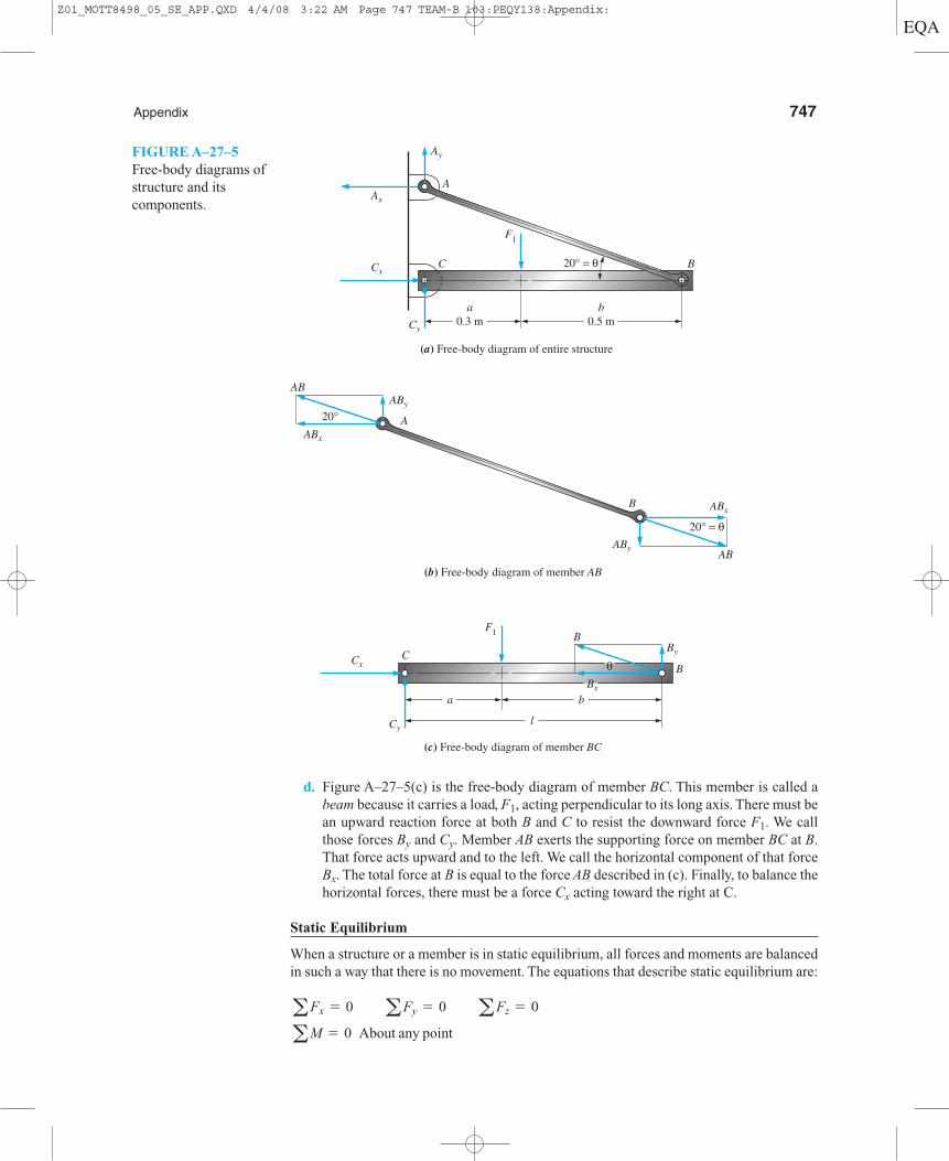
Appendix 747
d. Figure A–27–5(c) is the free-body diagram of member BC. This member is called abeam because it carries a load, F1, acting perpendicular to its long axis. There must bean upward reaction force at both B and C to resist the downward force F1. We callthose forces By and Cy. Member AB exerts the supporting force on member BC at B.That force acts upward and to the left. We call the horizontal component of that forceBx. The total force at B is equal to the force AB described in (c). Finally, to balance thehorizontal forces, there must be a force Cx acting toward the right at C.
Static Equilibrium
When a structure or a member is in static equilibrium, all forces and moments are balancedin such a way that there is no movement. The equations that describe static equilibrium are:
aM = 0 About any point
aFx = 0 aFy = 0 aFz = 0
0.3 ma
0.5 mb
A
BC 20° = θ
F1
Cx
Ax
Ay
Cy
(a) Free-body diagram of entire structure
AABx
20°
20° = θ
ABy
ABy
ABxB
AB
AB
(b) Free-body diagram of member AB
l
F1
Cx BBx
θBy
B
(c) Free-body diagram of member BC
ba
Cy
C
FIGURE A–27–5Free-body diagrams ofstructure and itscomponents.
Z01_MOTT8498_05_SE_APP.QXD 4/4/08 3:22 AM Page 747 TEAM-B 103:PEQY138:Appendix:

748 Appendix
The first three equations state that the sum of all forces in any direction must add to zero.We typically do the analysis in three perpendicular directions, x, y, and z. The fourth equa-tion states that the sum of the moments about any point must be zero.
We use the equations of equilibrium to determine the values of unknown forces andmoments when certain forces and moments are known and when suitable free-bodydiagrams are available.
Example from Figures A–27–4 and A–27–5
Determine the forces on all members and at all joints for the structure shown in FigureA–27–4. The given data are: F1 � 18.0 kN, a � 0.3m, b � 0.5m, � � 20°.
Solution. We use the free-body diagrams shown in Figure A–27–5.
Step 1. Use part (c) first. We sum moments about point C to find the force By.
Then,
We then sum moments about point B to find the force Cy.
Then,
We can check to see if all vertical forces are balanced by summing forces in the verticaldirection.
Step 2. Consider the forces acting at B. We know that By � 6.75 kN. We also knowthat the total resultant force, B, acts at an angle of 20° above the horizontal toward the left.This is because it is applied through the pin by the force AB. The free-body diagram in(b) indicates that AB acts along the direction of the member AB because it is a two-forcemember. We can then say,
Then,
Step 3. The forces acting at pin B on both member AB and member BC must beequal and opposite because of the principle of action-reaction. Therefore, the axial forceon member AB is: AB � 19.74 kN. The force AB acts at both A and B along the line betweenthe two pins in a manner that places the member AB in tension. The components of AB atpin A are equal to the components at pin B, but they act in opposite directions.
Bx = B cos 20° = (19.74 kN)(cos 20°) = 18.55 kN
B = By �(sin 20°) = (6.75 kN) �(sin 20°) = 19.74 kN
Bx = B cos 20°
By = B sin 20°
aFy = Cy + By - F1 = 11.25 kN + 6.75 kN - 18.0 kN = 0 (Check)
Cy = (18.0 kN)(0.5 m)�(0.8 m) = 11.25 kN
aMB = 0 = F1b - Cy l = (18.0 kN)(0.5 m) - Cy (0.8 m)
By = (18.0 kN)(0.3 m) �(0.8 m) = 6.75 kN
aMC = 0 = F1 a - By l = (18.0 kN)(0.3 m) - By (0.8 m)
Z01_MOTT8498_05_SE_APP.QXD 4/3/08 1:19 AM Page 748 TEAM-B 103:PEQY138:Appendix:
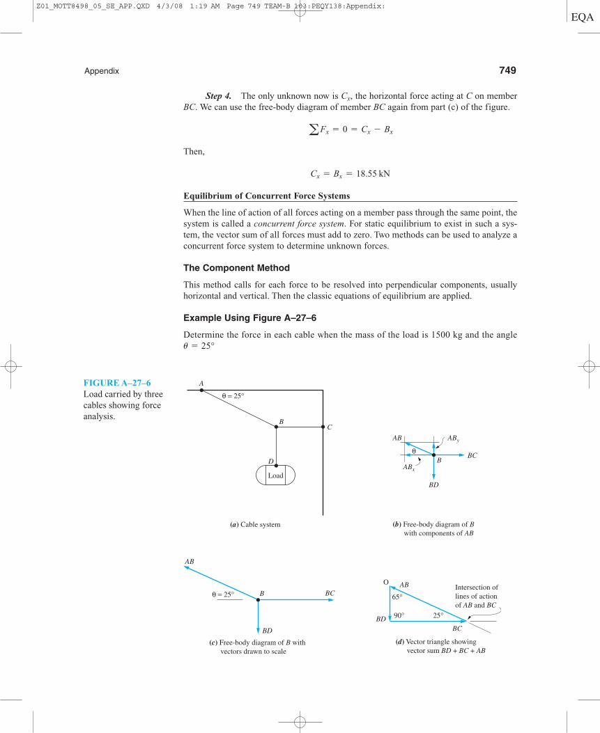
Appendix 749
Step 4. The only unknown now is Cx, the horizontal force acting at C on memberBC. We can use the free-body diagram of member BC again from part (c) of the figure.
Then,
Equilibrium of Concurrent Force Systems
When the line of action of all forces acting on a member pass through the same point, thesystem is called a concurrent force system. For static equilibrium to exist in such a sys-tem, the vector sum of all forces must add to zero. Two methods can be used to analyze aconcurrent force system to determine unknown forces.
The Component Method
This method calls for each force to be resolved into perpendicular components, usuallyhorizontal and vertical. Then the classic equations of equilibrium are applied.
Example Using Figure A–27–6
Determine the force in each cable when the mass of the load is 1500 kg and the angle� � 25°
Cx = Bx = 18.55 kN
aFx = 0 = Cx - Bx
A
B
Load
(a) Cable system
D
C
θ = 25°
AByAB
(b) Free-body diagram of B with components of AB
Bθ
ABx
BC
BD
AB
(c) Free-body diagram of B with vectors drawn to scale
BC
BD
Bθ = 25°
O
BD
AB
BC
65°
90° 25°
Intersection oflines of actionof AB and BC
(d) Vector triangle showing vector sum BD + BC + AB
FIGURE A–27–6Load carried by threecables showing forceanalysis.
Z01_MOTT8498_05_SE_APP.QXD 4/3/08 1:19 AM Page 749 TEAM-B 103:PEQY138:Appendix:
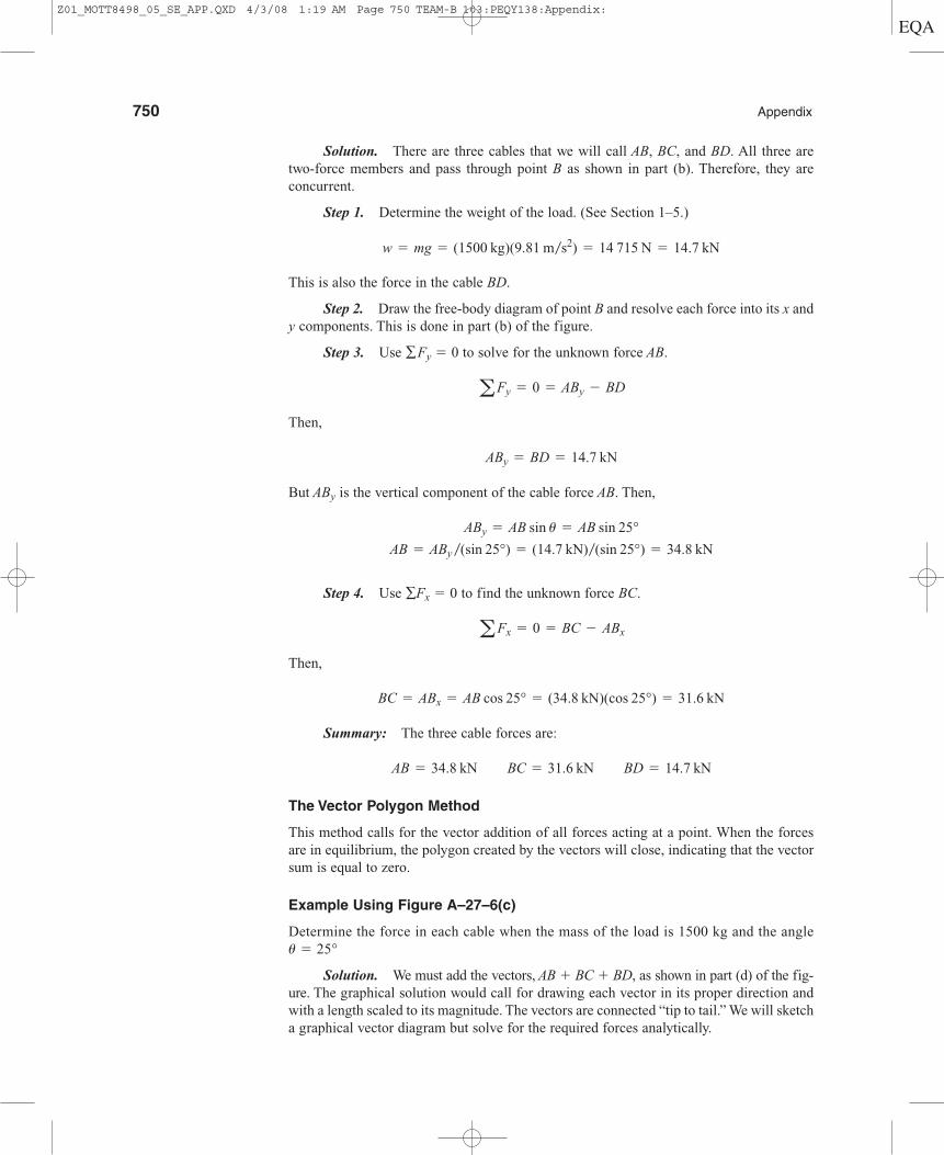
750 Appendix
Solution. There are three cables that we will call AB, BC, and BD. All three aretwo-force members and pass through point B as shown in part (b). Therefore, they areconcurrent.
Step 1. Determine the weight of the load. (See Section 1–5.)
This is also the force in the cable BD.
Step 2. Draw the free-body diagram of point B and resolve each force into its x andy components. This is done in part (b) of the figure.
Step 3. Use ∑Fy � 0 to solve for the unknown force AB.
Then,
But ABy is the vertical component of the cable force AB. Then,
Step 4. Use ∑Fx � 0 to find the unknown force BC.
Then,
Summary: The three cable forces are:
The Vector Polygon Method
This method calls for the vector addition of all forces acting at a point. When the forcesare in equilibrium, the polygon created by the vectors will close, indicating that the vectorsum is equal to zero.
Example Using Figure A–27–6(c)
Determine the force in each cable when the mass of the load is 1500 kg and the angle� � 25°
Solution. We must add the vectors, AB � BC � BD, as shown in part (d) of the fig-ure. The graphical solution would call for drawing each vector in its proper direction andwith a length scaled to its magnitude. The vectors are connected “tip to tail.” We will sketcha graphical vector diagram but solve for the required forces analytically.
AB = 34.8 kN BC = 31.6 kN BD = 14.7 kN
BC = ABx = AB cos 25° = (34.8 kN)(cos 25°) = 31.6 kN
aFx = 0 = BC - ABx
AB = ABy �(sin 25°) = (14.7 kN)�(sin 25°) = 34.8 kN
ABy = AB sin u = AB sin 25°
ABy = BD = 14.7 kN
aFy = 0 = ABy - BD
w = mg = (1500 kg)(9.81 m�s2) = 14 715 N = 14.7 kN
Z01_MOTT8498_05_SE_APP.QXD 4/3/08 1:19 AM Page 750 TEAM-B 103:PEQY138:Appendix:
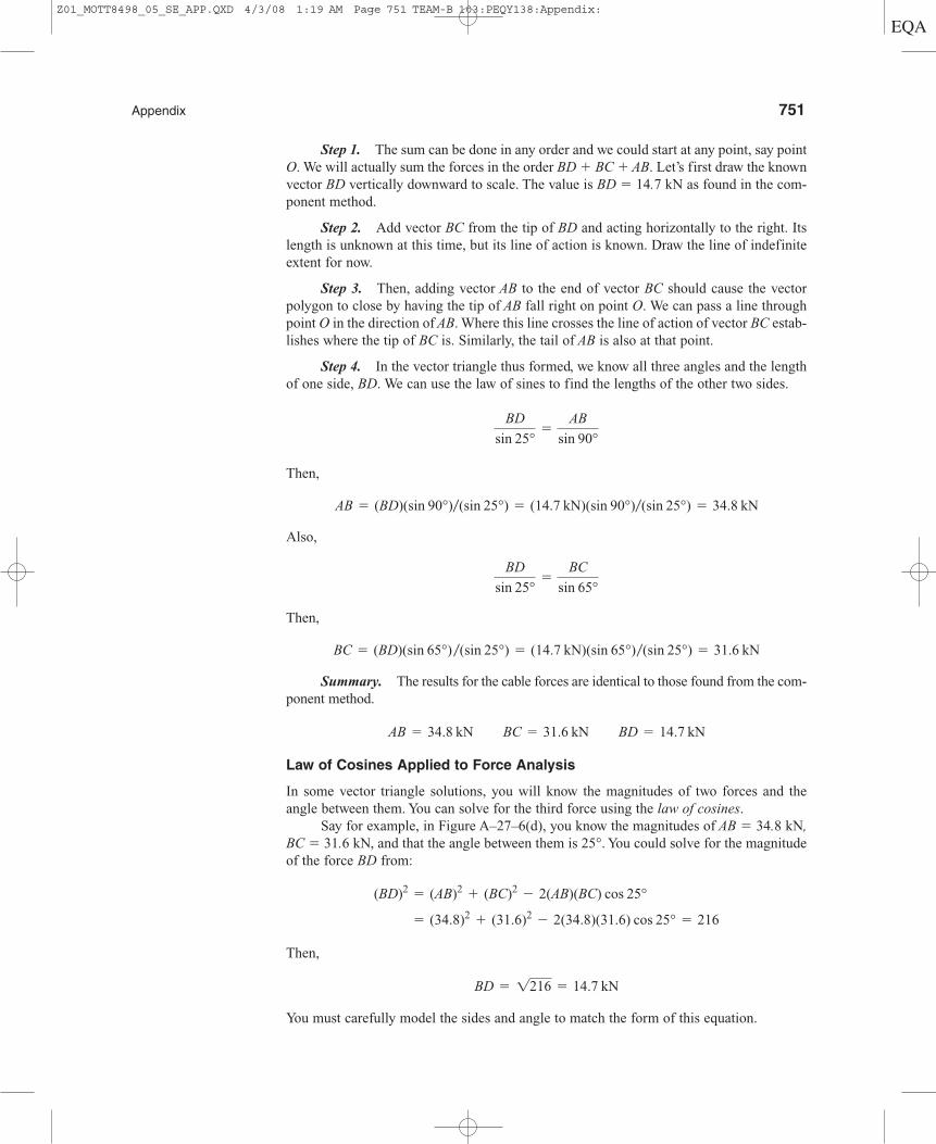
Appendix 751
Step 1. The sum can be done in any order and we could start at any point, say pointO. We will actually sum the forces in the order BD � BC � AB. Let’s first draw the knownvector BD vertically downward to scale. The value is BD � 14.7 kN as found in the com-ponent method.
Step 2. Add vector BC from the tip of BD and acting horizontally to the right. Itslength is unknown at this time, but its line of action is known. Draw the line of indefiniteextent for now.
Step 3. Then, adding vector AB to the end of vector BC should cause the vectorpolygon to close by having the tip of AB fall right on point O. We can pass a line throughpoint O in the direction of AB. Where this line crosses the line of action of vector BC estab-lishes where the tip of BC is. Similarly, the tail of AB is also at that point.
Step 4. In the vector triangle thus formed, we know all three angles and the lengthof one side, BD. We can use the law of sines to find the lengths of the other two sides.
Then,
Also,
Then,
Summary. The results for the cable forces are identical to those found from the com-ponent method.
Law of Cosines Applied to Force Analysis
In some vector triangle solutions, you will know the magnitudes of two forces and theangle between them. You can solve for the third force using the law of cosines.
Say for example, in Figure A–27–6(d), you know the magnitudes of AB � 34.8 kN,BC � 31.6 kN, and that the angle between them is 25°. You could solve for the magnitudeof the force BD from:
Then,
You must carefully model the sides and angle to match the form of this equation.
BD = 1216 = 14.7 kN
= (34.8)2+ (31.6)2
- 2(34.8)(31.6) cos 25° = 216
(BD)2= (AB)2
+ (BC)2- 2(AB)(BC) cos 25°
AB = 34.8 kN BC = 31.6 kN BD = 14.7 kN
BC = (BD)(sin 65°) �(sin 25°) = (14.7 kN)(sin 65°)�(sin 25°) = 31.6 kN
BD
sin 25°=
BC
sin 65°
AB = (BD)(sin 90°)�(sin 25°) = (14.7 kN)(sin 90°)�(sin 25°) = 34.8 kN
BD
sin 25°=
AB
sin 90°
Z01_MOTT8498_05_SE_APP.QXD 4/3/08 1:19 AM Page 751 TEAM-B 103:PEQY138:Appendix:
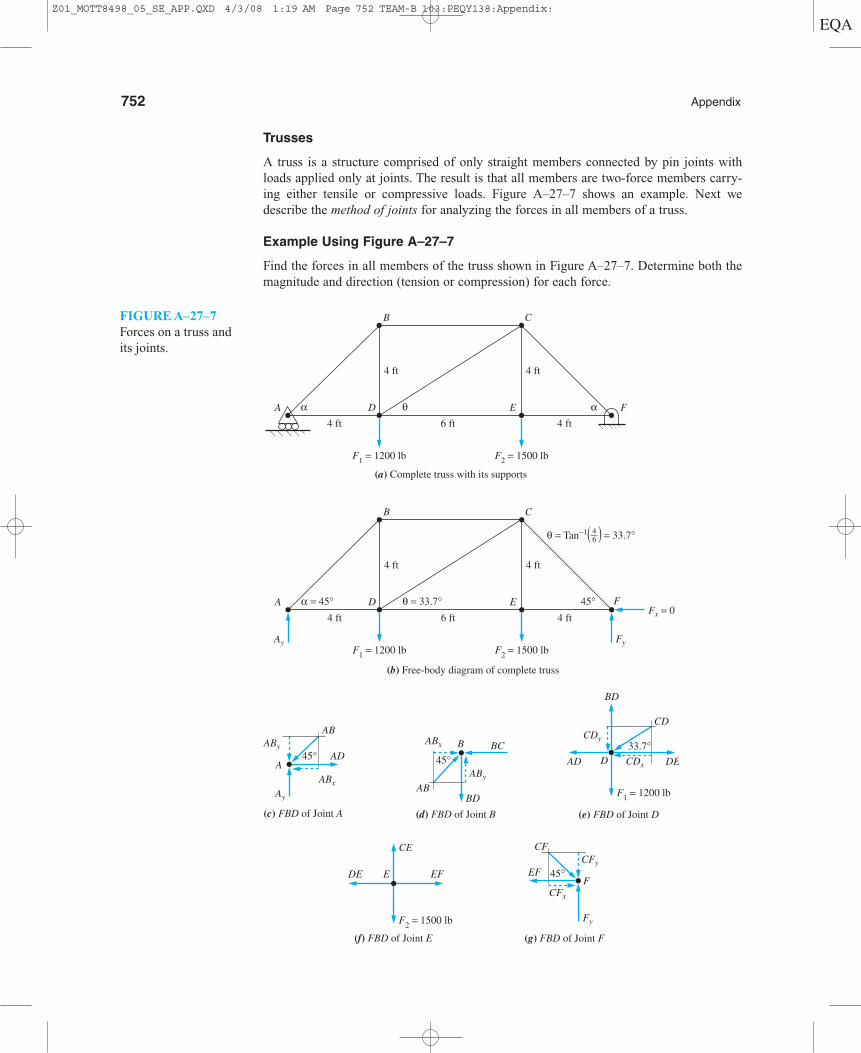
752 Appendix
Trusses
A truss is a structure comprised of only straight members connected by pin joints withloads applied only at joints. The result is that all members are two-force members carry-ing either tensile or compressive loads. Figure A–27–7 shows an example. Next wedescribe the method of joints for analyzing the forces in all members of a truss.
Example Using Figure A–27–7
Find the forces in all members of the truss shown in Figure A–27–7. Determine both themagnitude and direction (tension or compression) for each force.
F1 = 1200 lbAy Fy
F2 = 1500 lb
Fx = 0
(b) Free-body diagram of complete truss
B C
D E FA α = 45° 45°θ = 33.7°
θ = Tan−1 = 33.7°
4 ft 4 ft6 ft
4 ft 4 ft
46
F1 = 1200 lb F2 = 1500 lb
(a) Complete truss with its supports
B C
D E FA α αθ4 ft 4 ft6 ft
4 ft 4 ft
Ay
ABy
(c) FBD of Joint A
AB
AD
ABx
A45°
CE
EFDE E
F2 = 1500 lb
(f) FBD of Joint E
CDy
CD
CDxAD DED
BD
F1 = 1200 lb
(e) FBD of Joint D
33.7°
CFy
Fy
(g) FBD of Joint F
CFx
CF
EFF
45°
ABy
ABBD
(d) FBD of Joint B
BCBABx
45°
( )
FIGURE A–27–7Forces on a truss andits joints.
Z01_MOTT8498_05_SE_APP.QXD 4/3/08 1:19 AM Page 752 TEAM-B 103:PEQY138:Appendix:
Appendix 753
Analysis by Method of Joints
There are nine members in the truss. The general method for finding the forces in eachmember is described next.
a. Solve for the reactions at the supports for the entire truss.
b. Isolate one joint as a free body and show all forces acting on it. The selected jointmust have at least one known force acting on it. It is recommended that there be nomore than two unknown forces.
c. When a member is in tension, the force pulls out on the joint at either end. Conversely,a compression member pushes into a joint. Try to draw unknown forces in the properdirection that will ensure that the joint is in equilibrium.
d. Use the equations of static equilibrium for forces in the horizontal and vertical direc-tions to determine the unknown forces at the selected joint.
e. Forces found at the first joint become known forces for analyzing other joints. Moveto nearby joints and repeat steps b, c, and d repeatedly until the forces in all jointshave been found.
Completion of the Analysis of the Truss in Figure A–27–7
Step 1. Using the entire truss as a free body, solve for the support reactions at jointsA and F. See part (b) of the figure.Sum moments about support A to find support force Fy at point F.
Sum moments about support F to find support force Ay at point A.
Step 2. Isolate joint A as a free body. See part (c) of the figure. Work with compo-nents of the force AB. ABx � AB cos 45°. ABy � AB sin 45°.
Then,
Step 3. Isolate joint B as a free body. See part (d) of the figure.
BC = 1286 lb CompressionaFx = 0 = ABx - BC = 1286 lb - BC
BD = 1286 lb Tension
AD = ABx = AB cos 45° = (1818 lb)(cos 45°) = 1286 lb Tension
aFx = 0 = AD - ABx
AB = ABy �(sin 45°) = (1286 lb) �(sin 45°) = 1818 lb Compression
ABy = Ay = 1286 lb
aFy = 0 = Ay - ABy
Ay = [(12 000 + 6000) lb ft]�14 ft = 1286 lb Upward
aMF = F1(10 ft) + F2(4 ft) - Ay(14 ft) = (1200 lb)(10 ft) + (1500 lb)(4 ft) - Ay(14 ft)
Fy = [(4800 + 15 000) lb ft] �14 ft = 1414 lb Upward
aMA = F1(4 ft) + F2(10 ft) - Fy(14 ft) = (1200 lb)(4 ft) + (1500 lb)(10 ft) - Fy(14 ft)
Z01_MOTT8498_05_SE_APP.QXD 4/3/08 1:20 AM Page 753 TEAM-B 103:PEQY138:Appendix:
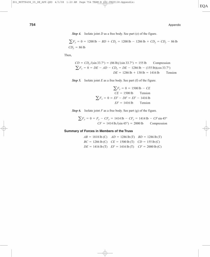
Step 4. Isolate joint D as a free body. See part (e) of the figure.
Then,
Step 5. Isolate joint E as a free body. See part (f) of the figure.
Step 6. Isolate joint F as a free body. See part (g) of the figure.
Summary of Forces in Members of the Truss
DE = 1416 lb (T) EF = 1416 lb (T) CF = 2000 lb (C)
BC = 1286 lb (C) CE = 1500 lb (T) CD = 155 lb (C)
AB = 1818 lb (C) AD = 1286 lb (T) BD = 1286 lb (T)
CF = 1414 lb �(sin 45°) = 2000 lb CompressionaFy = 0 = Fy - CFy = 1414 lb - CFy = 1414 lb - CF sin 45°
EF = 1416 lb TensionaFx = 0 = EF - DF = EF - 1416 lb
CE = 1500 lb TensionaFy = 0 = 1500 lb - CE
DE = 1286 lb + 130 lb = 1416 lb TensionaFx = 0 = DE - AD - CDx = DE - 1286 lb - (155 lb)(cos 33.7°)
CD = CDy �(sin 33.7°) = (86 lb)>(sin 33.7°) = 155 lb Compression
CDy = 86 lb
aFy = 0 = 1200 lb - BD + CDy = 1200 lb - 1286 lb + CDy = CDy - 86 lb
754 Appendix
Z01_MOTT8498_05_SE_APP.QXD 4/3/08 1:20 AM Page 754 TEAM-B 103:PEQY138:Appendix:


