

MOUNTING SYSTEMS FOR SOLAR INSTALLATIONS

2 32
PhOTOvOLTAIcS OvERvIEw OF cONTENTS
chapters Pages
0 The small solar lexicon 21 Rail system 4-8
1.1 Mounting rails 4-51.2 Sliding block 61.3 Made-to-order mounting rails 61.4 Simple cross bracing 71.5 Profile connectors 8
2 Accessories made of aluminium 93 Modular assembly 11-13
3.1 Module clamps for frames modules 103.2 Screws and accessories for module clamps 113.3 Use of Allen screws for different module heights 113.4 Module clamps KlickFIX 123.5 Module clamps for glass modules (with FirstSolar approval) 13
4 Solar fixings for tiled roofs 14-164.1 Roof hooks and accessories made of stainless steel 144.2 Roof hooks made of aluminium 154.3 Support plates for roof hooks, aluminium 16
5 Solar fixings for sheet metal and Eternit (asbestos-cement) roofs 17-225.1 Dowell screws for timber supporting structures 17-185.2 Pre-assembled dowel screws for timber supporting structures 195.3 Approved dowel screws for timber supporting structures 205.4 Approved dowel screws for steel supporting structures 205.5 Adaptor plates for dowel screws 215.6 Accessories for sheet-metal and Eternit (asbestos-cement) roofs 22
6 Accessories for flat and sheet roofs 23-246.1 Flat-roof elevation stand 236.2 Flat roof supports for flat roofs 24
7 Open-land installations 258 Screw accessories, solar 26-299 Enquiry form for special roof hooks 30-32
10 Enquiry form for special elevation triangles 3311 Global radiation and wind zone - EPDM rubbes 34-35
12 Mounting Instructions 36-51Pitched roof 37-47
1 General Information 37-402 System Overview 38-393 Possibilities for attaching the Systems to a Roof 40-414 Mounting Step: Pitched Roof Framework 42-435 Mounting the Rail Connectors 446 Mounting Step: in Crossbar Combination 457 Attaching framed PV Modules 468 Attaching frameless PV Modules 479 Flat roof mounting instructions 48-49
10 Article List - Accessories 50-5111 Contact 55
Photovoltaics
Photovoltaics is defined as the direct conversion of radiation energy (predominantly solar radiation) into electrical energy. It has been in use ever since it was first adopted for supplying energy to space satellites from solar cells in 1958. It is now used throughout the world to supply electrical power on roof surfaces, parking meters, soundabsorbing walls and open spaces. The name is made up of
two parts: photos – the Greek word for light – and Volta – after Ales-sandro Volta, a pioneer in electrical technology. Photovoltaics forms part of the extensive area of solar technology which also includes other technical utilisations of solar energy.
PROGRAMMA DI PRODUZIONE 2011Versione: 10/2010 • con riserva di modifiche
The best connections
Potenziale
Inox-Mare solar assembly systems. A support for the next generation.Solar energy is growing in popularity. It is sustainable utilising the natural resources of the planet and reduces energy costs making it economically viable and sensible. For these reasons alone more and more home owners and commercial properties are turning to solar systems as a source of supply for their energy needs. Inox-Mare have developed a long term installation mounting system which is both robust and durable, it is easy to fit regardless of the various
types of roof structures. With nearly forty years experience in the field of stainless steel fastener and fixing devices we have combined our technical expertise and produced a high quality system which satisfies the needs of our customers for the practical and ease of assembly. By doing so we meet the strict requirements and security of DIN 1055 that certifies the quality of our products.The Inox-Mare mounting system has been designed to withstand snow and all weather conditions.
The potential which can be achieved is very high: Despite the ap-parently unfavourable conditions in Germany, using the technology which is available today, approximately 2% of the total area of the country is theoretically sufficient to yield enough electrical energy to meet the total annual requirements of the country. The objection that the area in Central Europe would not be sufficient to support a significant proportion of photovoltaics for energy production is therefore not tenable. Also, the required surface area could be found
by utilising previously built structures (mainly roofs) without building over new ground. This theoretical evaluation of 100% coverage by photovoltaics does not represent the aim of implementation but me-rely serves to show the magnitude of the surface requirement. In the long term, therefore, photovoltaics can make a significant con-tribution to climate protection and the saving of resources, even in Germany.

4 5
Item no. Figure Item comments Box
9664-w 15Mounting rail
40 x 40 mm
Length: 6.1 m
Span width: 1.6 m*
Connection at the side: Sliding block M8
Connection top: Sliding block M8
1
9664-w 16 Mounting rail
80 x 40 mm
Length: 6.1 m
Span width: 3.2 m*
Connection at the side: Sliding block M8
Connection top: Sliding block M8
1
9664-w 200Heavy duty
rail
100 x 80 mm
Length: 6.0 m
Diverse Anbindungsmöglichkeiten
Span width: > 4 Meter
1
NEw
9664-w 2-26
Mounting rail
80 x 40 mm
Length: 6.1 m
Structural analysis: similar to 9664-W 2
Can be combined with mounting plates 9785-W 26 for additional side
anchoring (e.g. for cross-linking without angles)
1
9664-w 31 Trapezoidal rail
Length: depending on requirements
The profile can be bolted or clinched directly to the trapezoidal sheet.
Statistics have to be check.
Top channel for sliding block M8
1
* Assumed loads:
• Snow load sk = 1.21 kN/m2
• Module load: 0.22 kn/m2
• Wind load: Wsuction = -0.80 kn/m2 Wpressure = 0.40 kn/m2
RAIL SYSTEMMOUNTING RAILS
RAIL SYSTEMMOUNTING RAILS
1.1 - Mounting rails
Item no. Figure Item comments Box
9664-w 1Mounting rail
40 x 40 mm
Length: 6.1 m
Span width: 1.6 m*
Connection below: DIN 933 M10
(length according to customer requirement)
Connection top: Sliding block M8
1
NEw
9664-Light1
Mounting rail
50 x 39 mm
Length: 6,1 m
Span width: 1,55 m*
Connection below: DIN 933 M10
Connection above: Sliding block M8
cross bracing with 1 profile possible with mounting plates 9785-W26
1
9664-w 2Mounting rail
80 x 40 mm
Length: 6.1 m
Span width: 3.2 m*
Connection below: DIN 933 M10
(length according to customer requirement)
Connection top: Sliding block M8
1
9664-w 3Mounting rail
40 x 40 mm
Length: 6,1 m
Span width: 1,6 m*
Connection below: DIN 933 M10
(length according to customer requirement)
Connection top: Square nut M8 oder Hexagon nut M8
1
NEw
9664-Light 3
Mounting rail
50 x 37 mm
Length: 6,1 m
Span width: 1,55 m*
Connection below: DIN 933 M10 (length according to customer req.)
Connection above: Sliding block M8 or heagon nut M8
cross bracing with 1 profile possible with mounting plates 9785-W26
1

6 7
1.4 - Simple cross bracing
Item no. Figure Item comments Box
9664-w 15
Mounting rail
40 x 40 mm
for lateral fastening
Length: 6.1 m
Span width: 1.6 m*
Connection at the side: Sliding block M8
Connection top: Sliding block M8
For horizontal laying with bracket 9701-W 14
1
9664-w 16Mounting rail
80 x 40 mm
Length: 6.1 m
Span width: 3.2 m*
Connection at the side: Sliding block M8
Connection top: Sliding block M8
For horizontal laying with bracket 9701-W 14
1
9701-w 14Cross bracing
connection bracket
Mounting 9664-W 15 or W 16 on 9664-W 1.
W 2 or W 3 with 3 sliding blocks and screws DIN 912-2-8*16
100
* Assumed loads:
• Snow load sk = 1.21 kN/m2
• Module load: 0.22 kn/m2
• Wind load: Wsuction = -0.80 kn/m2 Wpressure = 0.40 kn/m2
RAIL SYSTEMSLIDING BLOCK / MADE-TO-ORDER MOUNTING RAILS
RAIL SYSTEMSIMPLE CROSS BRACING
1.2 - Sliding block
Item no. Figure Item comments Box
9431-120901Sliding block
Swivel
for M8
VE = 100 pieces
ALUMINIUM
Ball from A2
100
1.3. Made-to-order mounting rails
We can supply any profile emaginable.
even according to your drawing.
Please enquire!

98
1.6 - Profile connectors
Item no. Figure Item comments Box
9751-w 12Profile
connectors
200 mm
for mounting rails 9664-W 1/3/15/22
They also require 4 selfdrilling screws /connectors for fastening
100
9751-w 18
Profile connector slide-in
200 mm
for mounting rails 9664-W 1/3/15/16
W 1/3/15 = 1 connector / connector
W 16 = 2 connectors / connectors
50
9751-w 18 L
Profile connector
slide-in light
200 mm
for mounting rails type light
you need 2 pieces / connectors
for 9664-Light 1 and 9664-Light 3
50
9557-2-200*40
Profile connector
4-hole
200 x 40 x 5 mm
Round hole M10 Stainless steel
A2
for mounting rails 4 x hammerhead screws W S9420 M8x20 + flange
nuts with serration 9345-2-8 required
25
9672-FS- connector
Profile connector slide-in
heavy load
for Heavy duty rail 9664-W 200
Sie benötigen 2 Stück / Verbindung
125
AccESSORIES MADE OF ALUMINIUM RAIL SYSTEMPROFILE CONNECTORS
2 - Accessories made of aluminium
Item no. Figure Item comments Box
9671-40*40*3Angle profile ALU
40*40*3
Length: 6.05 metres
40 x 40 x 40 x 3 mm from stock
Other lengths available on enquiry.
1
9671 Angle profile ALU
e.g. 40 x 40 x 4 lengths at 6.05 m
Lengths and other sizes depending on requirements
1
9671-w 20Z profile
ALUMINIUM
Z profile ALUMINIUM
Length: 6.1 metres
40 x 40 x 40 x 3 mm
Other sizes. e. g. 40 x 60 x
40 x 3. available on enquiry
1

10 11
MODULAR ASSEMBLYSCREWS AND ACCESSORIES FOR MODULE CLAMPS
MODULAR ASSEMBLYMODULE CLAMPS FOR FRAMED MODULES
3.1 - Module clamps for framed modules
Item no. Figure Item comments Box
9742-w 4-…End clamp
ALUMINIUM
Length: 70 mm
Width: 30 mm
Please specify module height.
50
9745-w 13Middle clamp
ALUMINIUM
Length: 70 mm
Width: 36 mm100
3.2 - Screws and accessories for module clamps
Item no. Item Box
Allen screws:
DIN 912 o DIN 9455
912-2-8*30 M8*30 mm 200
912-2-8*35 M8*35 mm 200
912-2-8*40 M8*40 mm 200
912-2-8*45 M8*45 mm 100
912-2-8*50 M8*50 mm 100
912-2-8*55 M8*55 mm 100
912-2-8*60 M8*60 mm 100
9250-2-8.4 Locking washer A2 8.4 mm 1000
3.3 - Use of Allen screws for different module heights
Module heightScrew for rail
with sliding blockLocking washer
(for sliding block channel only)Screw for rail with
square nut 1
32 mm Allen, M8 x 35 Allen, M8 x 35 or *40
34 mm Allen, M8 x 35 Allen, M8 x 35 or *40
35 mm Allen, M8 x 40 x Allen, M8 x 40 or *45
36 mm Allen, M8 x 40 x Allen, M8 x 40 or *45
38 mm Allen, M8 x 40 Allen, M8 x 40 or *45
40 mm Allen, M8 x 45 x Allen, M8 x 45 or *50
41 mm Allen, M8 x 45 x Allen, M8 x 45 or *50
42 mm Allen, M8 x 45 Allen, M8 x 45 or *50
45 mm Allen, M8 x 50 x Allen, M8 x 50 or *55
46 mm Allen, M8 x 50 x Allen, M8 x 50 or *55
50 mm Allen, M8 x 55 x Allen, M8 x 55 or *60
1 Both specified lengths can be used with these square nuts.

1312
3.4 - Module clamps plus clip connector KlickFIX
Item no. Figure Item comments Box
9742- clipE
End clamp ALU plus clip
Significantly higher tensile strength than conventional attachments due to
special aluminium alloy
End clamp fully assembled with screw, nut and clip connector
Please specify module height in your order/enquiry!
This convenient clip connection clicks into any top channel of the W profiles.
Reduced installation time saves you money!
50
9745- clipM
Centre clamp ALU
Significantly higher tensile strength than conventional attachments due to
special aluminium alloy
Centre clamp fully assembled with screw, nut and clip connector
Please specify module height in your order/enquiry!
This convenient clip connection clicks into any top channel of the W profiles.
Reduced installation time saves you money!
100
3.5 - Module clamps for glass modules
Item no. Figure Item comments Box
9745- laminate L
9742- laminate L
End clamp Middle clamp ALUMINIUM
• Practical clip connection
• UV resistant EPDM rubber
• Modular height adjustable
You also require one Allen screw DIN 912 A2 8x35
clamping range: 6-9 mm
100
9745- laminate-S
9742- laminate-S
Centre clamp End clamp
for glass modules
ALU
• Elastic sealing insert for optimal, friction-locked clamping
Also requires socket screws DIN 912 A2 8x12
clamping range: 6,8 mm
art. 9745: 390
art. 9742: 200
9745- laminate-JT
9742- laminate-JT
Centre clamp End clamp
for glass modules
ALU
Form rubber 6.8mm
• Patented design with EPDM rubber bed
• Convenient end stop prevents module damage
Also requires one socket screw DIN 912 A2 8x16
clamping range: 6,8 mm
100
MODULAR ASSEMBLYMODULE CLAMPS FOR GLASS MODULES
MODULAR ASSEMBLYMODULE CLAMPS PLUS CLIP CONNECTOR KLICKFIX

14 15
4.1 - Roof hooks and accessories made of stainless steel
Item no. Figure Item comments Box
9523-2-1508040Vario 40 roof
hook
Plate 150 x 80 x 5 mm
bottom bracket 40 mm
rounded hook 8 mm
Material: 1.4301
20
9521-2-150x60w
Roof hook small
Version B:
Plate 150 x 60 x 4 mm
Hook 30 x 5 mm
Height 130 mm
20
9521-2-180X80Roof hook stan-
dard
Plate 180 x 80 x 5 mm
Hook 35 x 6 mm
Height 139 mm
20
9521-2-180X80w
Roof hook standard
Plate 180 x 80 x 5 mm
Hook 35 x 6 mm
Height 139 mm
10
9525-2-140*56KRoof hook adjustable
Plate 144 x 56 x 5 mm
Hook 5 mm pre-assembled
Material: 1.4301
20
From Page 30 onwards, you will find an enquiry form for roof hook shapes which you cannot find here.
We recommend our special washer-head screws for fastening the roof hooks onto the rafter. (see heading „Screw accessories“)
4.2 - Aluminium roof hooks
Item no. Figure Item comments Box
9721-110004
+
9721-110001 Roof hooks. end-to-end
Consisting of base plate and
hook for clipping
For 32 mm battens
Height of base plate 46 mm
100
100
9726-110020
+
9721-110001
For 40 mm battens
Height of base plate 54 mm
100
100
9721-110004
+
9727-100000Roof hook. with height adjust-
ment on the hook
Consisting of base plate and pre-assembled
hook
For 32 mm battens
Height of base plate 46 mm
100
25
9726-110020
+
9727-100000
For 40 mm battens
Height of base plate 54 mm
100
25
9721-110004
+
9727-200000Roof hook for
vertical mounting
Consisting of base plate and pre-assembled
hook
On enquiry
For 32 mm battens
Height of base plate 46 mm
100
25
9726-110020
+
9727-200000
For 40 mm battens
Height of base plate 54 mm
100
25
From Page 30 onwards. you will find an enquiry form for roof hook shapes which you cannot find here.
We recommend our special washer-head screws for fastening the roof hooks onto the rafter. (see heading „Screw accessories“)
SOLAR FIXINGS FOR TILED ROOFSALUMINIUM ROOF HOOKS
SOLAR FIXINGS FOR TILED ROOFSROOF HOOKS AND ACCESSORIES MADE OF STAINLESS STEEL

16 17
4.3. Support plates for roof hooks, aluminium
Item no. Item Box
9731-2*130702 Support plate, 2 mm aluminium 100
9731-3*130703 Support plate, 3 mm aluminium 100
9731-5*130705 Support plate, 5 mm aluminium 100
5.1 - Approved dowel screws for timber supporting structures
Item no. Figure Item comments Box
9211-2-10*180Dowel screws
A2
Dowel Screw (WS9211)
hexagon head 7 AF
M10x180 mm thread length:
Metric: 100 mm wood: 60 mm
50
9211-2-10*200Dowel screws
A2
Dowel Screw (WS9211)
hexagon head 7 AF
M10x200 mm thread length :
Metric: 110 mm wood: 70 mm
50
9211-2-10*250Dowel screws
A2
Dowel screw (WS9211)
hexagon head 7 AF
M10x250 mm thread length:
Metric: 130 mm wood: 80 mm
50
9211-2-10*300Dowel screws
A2
Dowel screw (WS9211)
hexagon head 7 AF
M10x300 mm thread length:
Metric: 140 mm wood: 100 mm
50
9211-2-12*250Dowel screws
A2
Dowel screw (WS9211)
hexagon head 8 AF
M12x250 mm thread length:
Metric: 130 mm wood: 100 mm
50
SOLAR FIXINGS FOR ShEET METALAPPROVED DOWEL SCREWS FOR TIMBER SUPPORTING STRUCTURES
SOLAR FIXINGS FOR TILED ROOFSSUPPORT PLATES FOR ROOF HOOKS, ALUMINIUM

18 19
5.2 - Pre-assembled dowel screws for timber supporting structures
Item no. Figure Item comments Box
9215-2-...Dowel screws hexagon head. pre-assembled
Pre-assembled with 3 hexagon nuts DIN 934 A2 + 3 washers DIN 125 A2
+ EPDM gasket WS9218
All dimensions see above WS 9211 with this pre-assembled item availa-
ble from stock.
25
9216-2-...Dowel screws hexagon head. pre-assembled
Pre-assembled with 3 serrated nuts WS9345 A2 + EPDM seal WS9218
All dimensions see above WS 9211 with this pre-assembled item
available from stock.
25
9218-2-10EPDM- gasket
EPDM – seal approx. dowel screws M10
1000
9218-2-12EPDM- gasket
EPDM – seal approx. A for dowel screws M12
1000
Other pre-assembled items available on enquiry
5.1 - Approved dowel screws for timber supporting structures
Item no. Figure Item comments Box
9211-2-12*300-9
Dowel
screws
A2
Dowel screw (WS9211)
hexagon head 8 AF 12x300 mm
thread length : Metric: 140 mm
wood: 100 mm
50
9211-2-12*350
Dowel
screws
A2
Dowel screw (WS9211)
hexagon head 8 AF 12x350 mm
thread length : Metric: 180 mm
wood: 130 mm
50
SOLAR FIXINGS FOR ShEET METALPRE-ASSEMBLED DOWEL SCREWS FOR TIMBER SUPPORTING STRUCTURES
SOLAR FIXINGS FOR ShEET METALAPPROVED DOWEL SCREWS FOR TIMBER SUPPORTING STRUCTURES
20 21
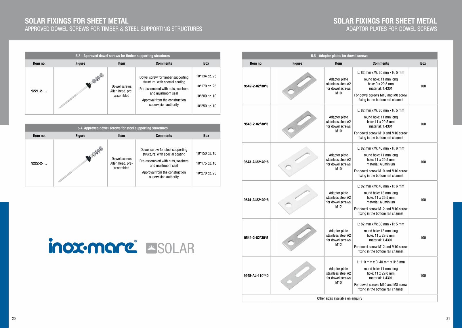
5.5 - Adaptor plates for dowel screws
Item no. Figure Item comments Box
9542-2-82*30*5
Adaptor plate stainless steel A2 for dowel screws
M10
L: 82 mm x W: 30 mm x H: 5 mm
round hole: 11 mm long hole: 9 x 29.5 mm material: 1.4301
For dowel screws M10 and M8 screw fixing in the bottom rail channel
100
9543-2-82*30*5
Adaptor plate stainless steel A2 for dowel screws
M10
L: 82 mm x W: 30 mm x H: 5 mm
round hole: 11 mm long hole: 11 x 29.5 mm
material: 1.4301
For dowel screw M10 and M10 screw fixing in the bottom rail channel
100
9543-AL82*40*6
Adaptor plate stainless steel A2 for dowel screws
M10
L: 82 mm x W: 40 mm x H: 6 mm
round hole: 11 mm long hole: 11 x 29.5 mm material: Aluminium
For dowel screw M10 and M10 screw fixing in the bottom rail channel
100
9544-AL82*40*6
Adaptor plate stainless steel A2 for dowel screws
M12
L: 82 mm x W: 40 mm x H: 6 mm
round hole: 13 mm long hole: 11 x 29.5 mm material: Aluminium
For dowel screw M12 and M10 screw fixing in the bottom rail channel
100
9544-2-82*30*5
Adaptor plate stainless steel A2 for dowel screws
M12
L: 82 mm x W: 30 mm x H: 5 mm
round hole: 13 mm long hole: 11 x 29.5 mm
material: 1.4301
For dowel screw M12 and M10 screw fixing in the bottom rail channel
100
9548-AL-110*40
Adaptor plate stainless steel A2 for dowel screws
M10
L: 110 mm x B: 40 mm x H: 5 mm
round hole: 11 mm long hole: 11 x 29.0 mm
material: 1.4301
For dowel screws M10 and M8 screw fixing in the bottom rail channel
100
Other sizes available on enquiry
SOLAR FIXINGS FOR ShEET METALADAPTOR PLATES FOR DOWEL SCREWS
SOLAR FIXINGS FOR ShEET METALAPPROVED DOWEL SCREWS FOR TIMBER & STEEL SUPPORTING STRUCTURES
5.3 - Approved dowel screws for timber supporting structures
Item no. Figure Item comments Box
9221-2-…Dowel screws
Allen head. pre-assembled
Dowel screw for timber supporting structure. with special coating
Pre-assembled with nuts, washers and mushroom seal
Approval from the construction supervision authority
10*134 pz. 25
10*170 pz. 25
10*200 pz. 10
10*250 pz. 10
5.4. Approved dowel screws for steel supporting structures
Item no. Figure Item comments Box
9222-2-…Dowel screws
Allen head. pre-assembled
Dowel screw for steel supporting structure. with special coating
Pre-assembled with nuts, washers and mushroom seal
Approval from the construction supervision authority
10*150 pz. 10
10*175 pz. 10
10*270 pz. 25

22 23
5.6 - Accessories for sheet metal
Item no. Figure Item comments Box
9664-w 31 Trapezoidal rail
Length: depending on requirements
The profile can be bolted directly to the trapezoidal sheet.
Top channel for sliding block M8
1
9671-w 20Z profile
ALUMINIUM
Z profile ALUMINIUM Length: 6.1 metres
40 x 40 x 40 x 3 mm
Other sizes available on enquiry
1
9583-KALZIP10Kalzip clamp,
angled M10
Kalzip clamp A2 with long slot for rail link M10
Assembled with screw/nut/washer
100
9581-…Trapezoidal
sheeting panel block A2
4-hole trapezoidal sheeting panel block for fastening directly to the
trapezoidal sheeting (only on request and with drawing,
statistics have to be checked)
Optionally with mounting plate, head-less screw or angle
50
Other sizes available on enquiry
6.1. Flat-roof elevation stand
Item no. Item Box
9785-w 2040
Flat roof elevation triangle. aluminium
• Folding
• Variable adjustment 20° to 40°
• Available from stock ready assembled
They require 8 x 9785-W 26 mounting plates per triangle. Diagonal struts
1
9785-w 26 100
1
Mounting plates for attaching the mounting rails to the triangle
Rigid support triangles made from angle section e.g. 40x40x3
or 40x40x5
Available in any custom angular dimension
AccESSORIES FOR FLAT AND ShEET ROOFSFLAT-ROOF ELEVATION STAND
SOLAR FIXINGS FOR ShEET METALACCESSORIES FOR SHEET METAL

24 25
Wagener & Simon WASI GmbH & Co. KG / Postfach 24 01 53 / 42231 Wuppertal / Tel.: 0202-2632-177
27
7. Freilandanlagen / Schwerlastprofil
Spezielle Aufständerungen, auch für Freilandanlagen, bieten wir Ihnen gerne auf Anfrage an.
WASI Schwerlastprofil Auch für Dachanlagen einsetzbar für
Spannweiten >4 Meter
Darstellung der verschiedenen Anbindungsmöglichkeiten an das WASI Schwerlastprofil
Vorkonfektionierte Bauelemente ab Lager verfügbar
OPEN LAND INSTALLATIONSAccESSORIES FOR FLAT AND ShEET ROOFSSAMPLE LOADING SOLUTION
7 - Open land installations
Special elevations, even for open-land installations, are available on Enquiry.
Inox Mare heavy load profile Also suitable for roof systems with spans >4 metres
Illustration of various options for connecting to the Inox Mare heavy load profile
Preassembled components available ex stock
6.2 - Sample loading solution
Combining various Inox Mare panels will provide you with a loa-ding surface for our adjustable flat roof support. The key items for this loading solution are listed at the right and shown below.
9664-W 16, 9701-W 14, 9664-W 31, 9785-W 2040, 9785-W 26 (plus additional standard connections
such as sliding blocks, socket screws, etc.)

26 27
b1
b2
k
8 - Screw accessories, solar
For information: Inox Mare Solar will not only supply you with our innovative solar items but also all the other rustproof connection elements. With 24.000 items permanently available in stock, Inox Mare is not just a supplier with one of the widest and deepest ranges of products on the market but also a global market leader in rust-proof connection elements – available in grades A2 to A4.
here is a small selection:
Item no. Figure Item comments Box
9810-0-.....*.....
Washer head screws with TX drive. stainless steel.
hardened
Approved by the construction supervision authority for faste-
ning roof hooks etc.
8*80 50
8*100 50
8*120 50
571-2-.....*.....Hexagon head – wood screws for fastening roof hooks etc.
8 x 80 10 x 80 8 x 100 10 x 100 8 x 120 10 x 120 8 x 140 10 x 140 8 x 160 10 x 160 8 x 180 10 x 180 8 x 200 10 x 200
100
912-2-.....*..... 912-4-.....*.....
Hexagon socket head cap screws in A2 and A4
according to DIN912
for fastening our module clamps etc. see table under
7.) Module clampsO.V. Table
933-2-.....*..... 933-4-.....*.....
Hexagon head screw full thread in A2 and A4 according
to DIN933
including size M10x25 for bottom rail channel Item
9664-W 1
O.V. Fasteners Catalogue
www.inoxmare.it
9415-2-.....*..... 9415-4-.....*.....
Hammerhead screw A2 and A4 for mounting rail Type
28/15
B1 Max 10,1 10,1 B2 22,8 22,8 K 4 5
M8 x 20 M10 x 20M8 x 25 M10 x 25M8 x 30 M10 x 30M8 x 35 M10 x 35
100
9021-2-.. . . . 9021-4-.. . . .
Washer with large external diameter in A2 and A4 according to DIN9021
for inside outside (mm) (mm)
M8 8.4 24.0 M10 10.5 30.0 M12 13.0 37.0
200
8 - Screw accessories, solar
Item no. Figure Item comments Box
125-2-..... 125-4-.....
Washer in A2 and A4 according to DIN125
for inside outside (mm) (mm)
M8 8.4 16.0 M10 10.5 20.0 M12 13.0 24.0
500
9250-2-..... Locking washers “S”
for inside outside (mm) (mm)
M8 8.4 13.0 M10 10.5 16.0 M12 13.0 18.0
M8: 1000M10: 500M12: 500
25201-4-.....*.....
Self-locking screw – retaining washer in A4 according to
DIN25201
for inside outside (mm) (mm)
M8 8.7 13.5 M10 10.7 16.0 M12 13.0 19.5
100
9480-2-.....*.....Security screw mushroom
head in A2 similar to ISO7380 (with TX drive and locking pin.)
M8 x 20M8 x 30M8 x 40
100
603-2-.....*..... 603-4-.....*.....
Mushroom head square neck bolt in A2 and A4 according to
DIN603
M10 x 20M10 x 25M10 x 25
50
ScREw AccESSORIES, SOLARScREw AccESSORIES, SOLAR

28 29
8 - Screw accessories, solar
Item no. Figure Item comments Box
557-2-..... 557-4-.....
Square nut in A2 and A4 according to DIN557
M8M10M12
M8: 200M10: 100M12: 100
934-2-..... 934-4-.....
Hexagon nut in A2 and A4 according to DIN934
M8M10M12
M8: 200M10: 100M12: 100
985-2-..... 985-4-.....
Stop nut. thin in A2 and A4 according to DIN985
M8M10M12
M8: 200M10: 100M12: 100
9345-2-..... 9345-4-.....
Hexagon nut similar to DIN 6923 with flange and serration
in A2 and A4
M8M10M12
M8: 200M10: 100M12: 100
9290-2-.....*..... 9290-4-.....*.....
Coupler nut with endto- end internal thread. round version in A2 and A4 according to Inox
Mare standard W S9290
M8M10M12
M8: 100M10: 50M12: 50
9300-2-.....*..... 9300-4-.....*.....
Coupler nut with endto- end internal thread. hexagonal ver-sion in A2 and A4 according to Inox Mare standard W S9300
M8M10M12
M8: 100M10: 50M12: 50
ScREw AccESSORIES, SOLARScREw AccESSORIES, SOLAR
8 - viti ed accessori relativi Solar
codice Figura Articolo Osservazioni Box
127-2-…… 127-4-……
Spring lock washer. A2 and A4 according to DIN127
M8M10M12
500
9305-2-……Shear nut according to W
standard WS9305
M8M10M12
M8: 200M10: 100M12: 100
9265-2-……Serrated locking washer
shape M (middle)
M8M10M12
200
9490-2-6,35
9490-2-6,25Ball for driving in
Balls Niro 304 6.25/6,35 mm Grade40
For securing Allen screws SW6
1000
9455-2-...Hexagon socket head cap
screws with serration under head
Available Ø 8 mm
length from 14 mm to 60 mm
sim. DIN 912
200
9500-...Polyamide washers
type A without chamfersim. DIN 125
M8: 1000M10: 500M12: 500
9510-...
Polyamide washers
outside diameter
~ 3x nominal thread diameter
sim. DIN 9021M8: 1000
M10: 1000M12: 500
9664-2-10*25
9664-2-10*30Hammer Head Screw
For mounting rail lower
connection100

30 31
A B c D E F G h A B c D E F G h I J
Wagener & Simon WASI GmbH & Co. KG / Postfach 24 01 53 / 42231 Wuppertal / Tel.: 0202-2632-177
32
�����������������������������
����������������
Bitte geben Sie uns Ihre Sondermaße an:
A B C D E F G H
Stückzahl:
Lieferadresse:
Für die Fertigung verwenden wir Edelstahl 1.4301, 5 mm Stärke, sofern nicht anders gewünscht.
������������ ������������������� !�������"##�$��������� %%�&�'�(������)���* �++�� ,�-�%%�&�'�(������)���! �++
Wagener & Simon WASI GmbH & Co. KG / Postfach 24 01 53 / 42231 Wuppertal / Tel.: 0202-2632-177
33
��������������.��$���/��0����������
�.��$���/��0����������
Bitte geben Sie uns Ihre Sondermaße an:
A B C D E F G H I J
Stückzahl:
Lieferadresse:
Für die Fertigung verwenden wir Edelstahl 1.4301, 5 mm Stärke, sofern nicht anders gewünscht.
������������ ������������������� !�������"##�$��������� %%�&�'�(������)���* �++�� ,�-�%%�&�'�(������)���! �++
Pan roof hooks Flat-tail roof hooks:
Please enter your particular dimensions: Please enter your particular dimensions:
Number of pieces: Number of pieces:
Delivery address: Delivery address:
We make them out of 5 mm thick stainless steel 1.4301 unless instructed otherwise. We make them out of 5 mm thick stainless steel 1.4301 unless instructed otherwise.
ORDER ShEET FOR FLAT-TAIL ROOF hOOKSORDER ShEET FOR PAN ROOF hOOKS

32 33
A B c D E F G h A B c D E F G
Wagener & Simon WASI GmbH & Co. KG / Postfach 24 01 53 / 42231 Wuppertal / Tel.: 0202-2632-177
34
����������������.���$����������
���.���$����������
Bitte geben Sie uns Ihre Sondermaße an:
A B C D E F G H
Stückzahl:
Lieferadresse:
Für die Fertigung verwenden wir Edelstahl 1.4301, 5 mm Stärke, sofern nicht anders gewünscht.
������������ ������������������� !�������"##�$��������� %%�&�'�(������)���* �++�� ,�-�%%�&�'�(������)���! �++
Wagener & Simon WASI GmbH & Co. KG / Postfach 24 01 53 / 42231 Wuppertal / Tel.: 0202-2632-177
35
��������������"���1���$"�2���
Bitte geben Sie uns Ihre Sondermaße an:
A B C D E F G
Material (z.B. Winkel 40x40x3):
Stückzahl:
Lieferadresse:
������������ ������������������� !�������"##�$��������� %%�&�'�(������)���* �++�� ,�-�%%�&�'�(������)���! �++
Slate roof hooks: Supports:
Please enter your particular dimensions:
Number of pieces:
Delivery address:
We make them out of 5 mm thick stainless steel 1.4301 unless instructed otherwise.
Please enter your particular dimensions:
Number of pieces:
Material (e.g. angle 40 x 40 x 3):
Delivery address:
ORDER ShEET FOR ELEvATIONSORDER ShEET FOR SLATE ROOF hOOKS

34 35
EPDM RUBBERSGLOBAL RADIATION AND wIND ZONES
EPM AND EPDM RUBBERS
Base materials to produce elastomers are NATURAL and SYNThETIc rubber.Vulcanization is a process whereby the rubber is cured and strengthened by treating it with sulphur, this process changes the polymer structure so increasing the elasticity and resistance to the effect of atmospheric oxygen together with many chemical substances. It also removes the negative properties of abrasiveness and viscosity.
EPM is a form of synthetic rubber. The E refers to Ethylene, P to Propylene and M refers to its ASTM classification standard D-1418. The M class includes rubbers having a saturated chain of the polymethylene type.Due to the lack of double bonds, this type of rubber cannot be cured with sulphur or any chemical releasing sulphur, but only with organic peroxides.
EPDM includes D for dienes which serve as crosslinks when curing with sulphur and resin, with peroxide cures the diene (or third monomer) acts as a coagent, wich provides resistance to unwanted tackiness, creep or flow when used.
Properties
The main properties of vulcanized EPDM are its outstanding resistance to heat, ozone and weather conditions, its resistance to ice and steam is also good. It has excellent electrical insulating properties.Impact resistance: 40/60%Elongation breakage: 150/500%heat resistance: Vulcanized peroxides withstand hot water and steam up to 200 °C without degradation. Low temperature resistance: approx minus 50°CGas permeability: high, not recommended.chemical resistance: hot water and steam between 130 to 200°Cglycol based brake fluids most detergents either organic or inorganic basedsalt solutions and oxidized substanceswater, phosphoric and glycol based hydraulic fluidssilicone oils and fatsmany ice solvents such as alcohols, ketones and esters; Skydrol 500 e 7000
Not recommended vulcanized EPDM and EPM with hydrocarbons in general.
common applications
Today the automotive industry is the largest user of EPDM rubber products, it is also widely used in the cable insulation industry, tubes, fittings, sealed cold room doors and numerous industries. With its characteristics EPDM is ideal as an insulating and sealing material for solar panels being used for both panel connections and a fixing support where EPDM washers also form part of the stainless steel system fixings.

XXXXXX
37
MOUNTING SYSTEMS FOR SOLAR INSTALLATIONSMONTAGE PITCHED ROOF
MOUNTING INSTRUcTIONS - PITchED ROOFGENERAL INFORMATION
Two things were absolutely decisive for our cons-
truction and development of the INOX MARE SO-
LAR mounting systems: simple installation and
durability that guarantees safety. That is what the
INOX MARE SOLAR program is based on.
Since individual characteristics are to be taken into
consideration for each and every roof, we request
that you submit a professional specification form
before the installation. You need to take particular
note of the static requirements. When mounting the
system, it is very important to observe and uphold
the corresponding norms and accident prevention
regulations.
We would like to point out that this mounting recom-
mendation illustrates the latest in technology and
many years of experience as to how our systems
can be installed on site.
Important norms and regulations:
BGV A2 Electrical systems and utilities
BGV C22 Construction works
BGV D35 Ladders and steps
BGV A1 Accident prevention regulations
DIN 1052-2 Timber structures:
Mechanical connections
DIN 1055 Load assumption for constructions
DIN 18299 General regulations for
construction works of every type
DIN 18451 Scaffold erections

3938
W 1 W 2
W 3
W 15 W 16
MOUNTING INSTRUcTIONS - PITchED ROOFSYSTEM OVERVIEW
MOUNTING INSTRUcTIONS - PITchED ROOFSYSTEM OVERVIEW

4140
1
2
3
4
5
6
MOUNTING INSTRUcTIONS - PITchED ROOFPOSSIBILITIES FOR ATTACHING SYSTEMS TO A ROOF
A majority of roof coverings are established with roof
tiles or roofing shingles. For these types of roofs, you
can use, for example, Vario roof hooks (for heavy
loads, PICTURE 1), adjustable roof hooks and stan-
dard roof hooks (PICTURE 2).
The assembly is described in the following.
These roof hooks are generally mounted to wooden
beams as per current wood norms. You can use the
following screws for this:
- DIN 571 A2 8*80/100/120 mm wooden screws
- WS 9810 A2 8*80/100/120 mm disk head screws
When covering with corrugated sheets (PICTURE
3) or trapezoidal metal sheets, you can use stock
screws and special consoles/blocks (PICTURE 4, 5
and 6). You select the corresponding stock screws
based on the respective sub-construction (for examp-
le, whether it’s wood or steel).
We offer the following possibilities here:
For wooden sub-constructions:
- See delivery programs 9215 + 9216 + 9217 + 9219
For steel sub-constructions:
- See delivery program 9222
- Approved solar panel fasteners!
You select the proper console based on the respec-
tive roof cover.
MOUNTING INSTRUcTIONS - PITchED ROOFPOSSIBILITIES FOR ATTACHING SYSTEMS TO A ROOF
If a roof penetration is not possible, you can conduct
a direct attachment to the provided trapezoidal or
corrugated sheet covers with a console/block (see
below) for a sheet mounting.
The consoles can be used up to a pitch of 30° de-
pending on the construction type. Before starting,
you must observe that the attachment of the sheet
to the sub-construction is sufficient and observe the
maximum load capacity of the sheet.

4342
1
2
1
2
3
4
MOUNTING INSTRUcTIONS - PITchED ROOFMOUNTING STEP: PITCHED ROOF FRAMEWORK
Determine the position of the roof hooks according
to the plan, which is provided in the project-related
assembly draft drawings.
Remove the roofing tiles at the respective positions
or, if possible, push them upwards. Position the res-
pective roof hooks; the hook must not push against
the roofing tile.
Depending on the roof hook model, you can adjust
the roof hooks at the height and in the sides, such
that it is located in the wave trough of the roofing
tile. Mount each roof hook with two wood screws
(for example, wooden screws DIN 571 or disk head
screws norm 9810*80 mm or M8*100 mm) to the
rafters.
If necessary, leave out the roofing tile above the
roof hooks at the spot where the roof hooks are
led through with hand-held cutters. The roof hooks
should not push up the roofing tile located above it.
In the case of mixed roofing tiles, we recommend
that you also leave out the lower tile.
MOUNTING INSTRUcTIONS - PITchED ROOFMOUNTING STEP: PITCHED ROOF FRAMEWORK
You mount the mounting rails for every module row
using various screws and bolts. (For PICTURE 2
and PICTURE 3, you can also feel free to use self-
locking DIN 985 bolts with ring washers; tightening
torque max. 18 Nm.)
Make sure you check the required rail connectors in
advance (see page 8.)
BILD 2:
DIN 933 A2 M10*25 (hexagon bolt) plus 9345 A2
M10 (locking nut)
oder
M10*25 (hammerhead bolt) plus 9345 A2 M10
(locking nut)
BILD 3:
Nutenstein 9431-120901 plus DIN 912 A2 M8*16
(cylinder head screw)
oder
DIN 603 A2 M8*25 (round-head screw) plus
9345 A2 M8 (locking nut)
BILD 4:
DIN 933 A2 M10*25 (hexagon bolt) plus 9345 A2
M10 (locking nut)
oder
M10*25 (hammerhead bolt) plus 9345 A2 M10
(locking nut)

4544
1
2
3
1
2
3
4
MOUNTING INSTRUcTIONS - PITchED ROOFMOUNTING THE RAIL CONNECTORS
To line up several system units next to each other,
you can use various connectors:
PICTURE 1: Half of the connector (W 18) is pushed
into the mounting rail. Then push the other moun-
ting rail onto the connector. Afterwards, you push
together the mounting rails with pressures.
PICTURE 2: Place the connector (W 12) above
the first mounting rail and click it into the existing
groove. Then click in the second mounting rail and
press them together. You then screw the connection
together with two drilling screws (tightening torque
8-10 Nm).
PICTURE 3: Make sure you have four hexagon
bolts for the connectors (featuring 4 holes) and then
push the first two screw heads into the lower chan-
nel of the first mounting rail. Then push the last two
screws into the other rails. You then attach all four
screws with (in each case) 4 bolts (tightening torque
10-12 Nm).
MOUNTING INSTRUcTIONS - PITchED ROOFMOUNTING STEP: IN CROSSBAR COMBINATION
When you attach non-framed PV modules, you may
have to conduct an assembly in the cross brace. This
is a particularly stabile construction. You must always
observe the module manufacturer instructions!
PICTURE 2: Connection of the two rails via a cross
brace bracket
- 912 A2/A4 8*16 (3x) cylinder head screw
- 9431 120901 (3x) t-nut
- 9701 W 14 bracket cross brace

4746
1
2.1
3
4
2.2
1.1
1.2
2.1
2.2
MOUNTING INSTRUcTIONS - PITchED ROOFMOUNTING STEP: PITCHED ROOF FRAMEWORK WITH FRAMELESS PV MODULES
Attachment examples for middle and end clamps:
PICTURE 2.1 : Swivel the t-nut into the upper rail
and click it in. Twist the end clamp with the respective
screw (depending on module height) into the t-nut.
Alternatively, you can attach the click-in kit in the up-
per channel of the rail and tighten it (tightening torque
up to a maximum of 18 Nm depending on module
manufacturer.) You can add a cover to the rails for
personal or appearance reasons (PICTURE 2.2).
PICTURE 3: Swivel the t-nut into the upper rail and
click it in. Twist the middle clamp with the respective
screw (depending on module height) into the t-nut.
Alternatively, you can attach the click-in kit in the
upper channel of the rail and tighten it (tightening
torque up to a maximum of 18 Nm depending on
module manufacturer.)
MOUNTING INSTRUcTIONS - PITchED ROOFMOUNTING STEP: PITCHED ROOF FRAMEWORK WITH FRAMELESS PV MODULES
PICTURE 2: Swivel the t-nut into the upper rail and
click it in. Twist the end clamp with a DIN 912 A2/A4
M8*35 mm screw into the t-nut and tighten it (tighte-
ning torque up to 15 Nm.)
PICTURE 1: Swivel the t-nut into the upper rail and
click it in. Twist the end clamp with a DIN 912 A2/A4
M8*35 mm screw into the t-nut and tighten it (tigh-
tening torque up to 15 Nm.)

4948
1
2
3
4
1
2
4
5
3
FLAT ROOF MOUNTING INSTRUcTIONSMOUNTING STEP: FLAT ROOF FRAMEWORKS FOR TRAPEZOIDAL SHEET METAL ROOFS
FLAT ROOF MOUNTING INSTRUcTIONSMOUNTING STEP: FLAT ROOF FRAMEWORKS FOR TRAPEZOIDAL SHEET METAL ROOFS
You then loosely lay the 9785-W26 mounting plate-
lets on the threaded necks and pull them tight with
a 985 A2/A4 M8 stop nut or 9345 A2/A4 M8 locking
nut (tightening torque 14-16 Nm).
PICTURE 1 – 4: LOWER attachment
The elevated mountings must now be attached to
the system units. Begin by placing a DIN 603 A2/A4
M8*25 mm carriage bolt in the upper section of the
system unit such that the thread(s) stick out.
PICTURE 5: Or alternatively:
Swivel and click the t-nut into the upper rails. Then
attach the 9785-W26 mounting platelets to the eleva-
ted mountings and to the rails via a DIN 912-2-8x16
cylinder head screw.
PICTURE 1 – 4: UPPER attachment
You now attach the system units for the module to
the triangle.
You do this by pushing DIN 933 A2/A4 M10*25 mm
hexagon bolt into the lower section of the system
unit such that the threads stick out.
Then you loosely lay the 9785-W26 mounting pla-
telet on the threaded necks and pull it tight with
an A2/A4 M10 locking nut (tightening torque 14-16
Nm).
The interval between the module rails for framed
modules that are to be mounted upright should
be approximately 1/2 of the module height. In this
case, always observe the module manufacturer in-
structions!

5150
MOUNTING INSTRUcTIONS - PITchED ROOFARTICLE LIST - ACCESSORIES
MOUNTING INSTRUcTIONS - PITchED ROOFARTICLE LIST - ACCESSORIES
Standard roof hooks
Trapezoidal sheet block
Adapter sheet
T-nut
Vario roof hooks
Hanger bolt
Mounting bracket
Section connector 9557
Section connector W 18
End clamp
End clamp for LAMINAT L glass module
End clamp for LAMINAT JT glass module
Section connector W 12
Middle clamp
Middle clamp for LAMINAT L glass module
Middle clamp for LAMINAT JT glass module


55
cONTAcT
INOX MAREVia Pomposa 51/i47900 Rimini (RN)Italy
Tel. +39 0541 794444Fax +39 0541 794491
WHAREHOUSEVia Cassoletta 2040056 Crespellano (BO)Italy

Via Pomposa 51/i47900 Rimini (RN)· Italy Tel. +39 0541 794444 Fax: +39 0541 794491
www.inoxmare.it [email protected]


