
1
EKC451
PROCESS DESIGN & ANALYSIS
TASK 3
Group members : ELAINE OOI CHIN WEN (117883)
NURUL EZATI MAT SIDEK (117903)
SOON KAH AIK (115884)
SYAFIQAH BINTI MAD ZIN (117909)
SYED ZULFADLI BIN SYED PUTRA
(115886)
Lecturer’s name : PROF MADYA DR. NORASYID AZIZ
Date of
submission
: 15th
December 2015
2
Table of Contents List of Figure........................................................................................................................................... 6
List of Tables .......................................................................................................................................... 7
Chapter 1 Problem Statement ................................................................................................................. 9
1.1 Letter of Transmittal ......................................................................................................................... 9
1.2 Methyl Tertiary Butyl Alcohol (TBA) Industry from Malaysia Chemical Industry Point of
View 11
1.2.1 Introduction to MTBE .............................................................................................................. 11
1.2.2 Application of MTBE: ............................................................................................................. 11
1.2.3 Benefits of MTBE in Gasoline................................................................................................. 12
1.2.4 History of the global perspectives on the usage of MTBE in Gasoline ................................... 13
1.2.5 The Advantages of MTBE over Ethanol .................................................................................. 15
1.2.6 Importance of MTBE to Malaysia Chemical Industry: ............................................................ 15
Chapter 2: Process Alternatives ............................................................................................................ 16
2.1 Three Process Alternatives for MTBE Production ......................................................................... 16
2.1.1 MTBE Production from Dehydrogenation of Isobutane .......................................................... 16
2.1.2 MTBE Production by Isobutylene from Refineries ................................................................. 21
2.1.3 MTBE Production by Isobutylene from TBA:......................................................................... 25
2.2 Comparison between Alternatives .................................................................................................. 22
2.3 Choice of Process ............................................................................................................................ 31
2.3.1 Safety and Health Issues: ......................................................................................................... 31
2.3.2 Environmental Issues: .............................................................................................................. 32
2.3.3 Public Issues: ........................................................................................................................... 33
2.3.4 Flexibility and Controllability:................................................................................................. 34
2.3.5 Economic Indicators and Market Background Analysis: ......................................................... 35
2.3.6 Current related problem of the plant to the environment and society: ..................................... 37
Chapter 3: Critical Assessment of the Process Chosen ......................................................................... 39
3.1 Capacity of Plant ............................................................................................................................. 39
3.2 Plant Location [51] [52] .................................................................................................................. 42
3.3 Complete Description of Process Chosen ....................................................................................... 44
3.4 Similar Plant in Malaysia [75] ........................................................................................................ 49
3.5 Environment, Safety and Health Concerns ..................................................................................... 50
3.5.1 Environmental Concerns .......................................................................................................... 50
3.5.2 Safety Concerns ....................................................................................................................... 51
3.5.3 Health Concern ........................................................................................................................ 52
3.6 Projected Demands/Supply for Next 10 years ................................................................................ 53
3
Chapter 4 Process Synthesis Structure and Analysis ............................................................................ 56
4.1 Input-Output Structure .................................................................................................................... 56
4.2 Feed and Product Specifications: .................................................................................................... 57
4.3 Price of all Product, By-Product and Raw Materials ...................................................................... 60
4.4 Destination Codes and Component Classification .......................................................................... 61
4.5 Utilities of the Process .................................................................................................................... 62
Chapter 5 Process Flow Diagram.......................................................................................................... 63
5.1 Block flow diagram for MTBE synthesis from isobutylene and methanol: ................................... 63
5.2 Process Flow Diagram .................................................................................................................... 65
5.3 Innovative Approach in Process Design ......................................................................................... 66
Chapter 6 Process Analysis ................................................................................................................... 67
6.1 Justification of Equipment .............................................................................................................. 69
6.2 Separation Operations Used in Production of MTBE ..................................................................... 72
Chapter 7: Mass Balance and Energy Balance of the Process Plant ..................................................... 74
7.1 Mixing Point ................................................................................................................................... 74
7.2 Feed Pump (P-101) ......................................................................................................................... 75
7.3Heat Exchanger (E-101) .................................................................................................................. 75
7.4 MTBE Reactor (R-101) .................................................................................................................. 76
7.5 MTBE Tower (T-101) ..................................................................................................................... 77
7.6 Condenser (E-102) .......................................................................................................................... 78
7.7 Reflux Pump (P-102) ...................................................................................................................... 79
7.8 Heater (E-104) ................................................................................................................................ 80
7.9 Bottom Reboiler (E-103) ................................................................................................................ 81
7.10 Methanol Absorber Column (T-102) ............................................................................................ 82
7.11 Methanol Recovery Tower (T-103) .............................................................................................. 83
7.12 Distillate Condenser (E-105) ........................................................................................................ 84
7.13 Reflux Pump (P-103) .................................................................................................................... 85
7.14 Methanol Recycle Pump ........................................................................................................... 86
7.15 Bottom Reboiler (E-106) .............................................................................................................. 87
7.16 Water Recycle Pump (P-105) ................................................................................................... 88
7.17 Water Mixing Point ................................................................................................................... 90
7.18 Comparison Aspen and Excel Calculation ................................................................................ 91
7.18.1 Mass Balance Justification between Manual Calculation and Aspen Simulation.............. 99
7.18.2 Energy Balance Justification between Manual Calculation and Aspen Simulation ........ 102
Chapter 8 Utilities and Other Issues ................................................................................................... 103
8.1 Utilities .......................................................................................................................................... 103
4
8.2 Amount of Waste Generated ......................................................................................................... 105
8.2.1 Liquid Waste .......................................................................................................................... 105
8.2.2 Vapor waste ........................................................................................................................... 105
8.2.3 Mode of liquid waste and vapour waste disposal................................................................... 106
Chapter 9 ............................................................................................................................................. 107
9.1 Mass transfer Equipment Design .................................................................................................. 107
9.1.1 Distillation Column, T-101 .................................................................................................... 107
9.1.2 METHANOL ABSORBER/SCRUBBER (T-102) ................................................................ 110
9.1.3Distillation Column, T-103 ..................................................................................................... 113
9.2 Heat Transfer Equipment .............................................................................................................. 116
9.2.1 Feed Heater, E-101 ................................................................................................................ 116
9.2.2 Condenser, E-102 ....................................................................................................................... 119
9.2.3 Reboiler, E-103 .......................................................................................................................... 122
9.2.4 Heater, E-104 ............................................................................................................................. 125
9.2.5 Condenser, E-105 ....................................................................................................................... 128
9.2.6 Reboiler, E-106 ...................................................................................................................... 131
9.3 Reactor Design .............................................................................................................................. 134
9.3.1 MTBE REACTOR (R-101) DESIGN .................................................................................... 134
9.4 Auxiliary Equipment Design ........................................................................................................ 137
9.4.1 Pump ...................................................................................................................................... 137
9.4.1.1 Feed Pump, P-101 ........................................................................................................... 138
9.4.1.2 Reflux Pump, P-102 ........................................................................................................ 139
9.4.1.3 Reflux Pump, P-103 ........................................................................................................ 140
9.4.1.4 Methanol Recycle Pump, P-104 ...................................................................................... 141
9.4.1.5 Water Recycle Pump, P-105 ........................................................................................... 142
9.5 Comparison between Aspen and Excel Calculation ..................................................................... 143
9.5.1 Mass Transfer Equipment ...................................................................................................... 143
9.5.1.1 Distillation Column, T-101 ............................................................................................. 143
9.5.1.2 Distillation Column, T-103 ............................................................................................. 144
9.5.2 Heat Transfer Equipment ....................................................................................................... 145
9.5.2.1 Feed Heater, E-101 ......................................................................................................... 145
9.5.2.2 Heater, E-104 .................................................................................................................. 146
9.5.3 Reactor Design ....................................................................................................................... 146
9.5.3.1 MTBE Reactor, R-101 .................................................................................................... 146
References ........................................................................................................................................... 147
Appendix A ......................................................................................................................................... 155
5
Thermodynamic Data of Reactants and Product ............................................................................. 155
Physical Data .................................................................................................................................. 157
MSDS of All Chemical Components in Process ............................................................................ 159
Appendix B ......................................................................................................................................... 216
Economic Potential ......................................................................................................................... 216
Appendix C ......................................................................................................................................... 221
Mass Transfer Equipment Design ................................................................................................... 221
Heat Transfer Equipment Design .................................................................................................... 283
Reactor Design ................................................................................................................................ 346
Auxiliary Equipment Design .......................................................................................................... 371
6
List of Figure Figure 1: MTBE Production Facility .................................................................................................... 17
Figure 2: Schematic Diagram of the Oleflex Isobutane Dehydrogenation Process .............................. 18
Figure 3: A simplified flow diagram of the Ethermax process ............................................................. 20
Figure 4: Typical Layout of MTBE Plant ............................................................................................. 21
Figure 5: Etherification Process in Packed Bed Reactor ...................................................................... 23
Figure 6: Liquid-liquid Extraction Column .......................................................................................... 24
Figure 7: Reaction Pathway for Indiect Conversion of TBA to MTBE (ARCO process)[23] ............. 25
Figure 8: Block Flow Diagram for Indirect Conversion of TBA to MTBE (ARCO process) .............. 26
Figure 9: Reaction Pathway for Direct Conversion of TBA to MTBE (formerly the Texaco Process,
now the Huntsman Process) [27] .......................................................................................................... 26
Figure 10: Mechanism of TBA to MTBE catalysed by sulfonic acid resin .......................................... 27
Figure 11: Block flow diagram for direct conversion of TBA to MTBE (formerly the Texaco process;
now the Huntsman process) .................................................................................................................. 27
Figure 12: History and projections of global MTBE supply and demand from 2010 to 2020 ............. 37
Figure 13: Fuel ether demand in Asia from 1992 to 2011 .................................................................... 40
Figure 14: The amount of new vehicles registered in Malaysia [55] .................................................... 40
Figure 15: Malaysia motor gasoline consumption per year [56] ......................................................... 41
Figure 16: Structure of the global production of MTBE by country, 2013 .......................................... 41
Figure 17: The Location of Plant at Teluk Kalong, Terengganu, Malaysia.......................................... 42
Figure 18: Etherification Process in Packed Bed Reactor .................................................................... 44
Figure 19: Distillation Column Process for MTBE .............................................................................. 46
Figure 20: Vapor-liquid equilibrium and chemical equilibrium of the ternary system MTBE, methanol
and isobutene [105] ............................................................................................................................... 47
Figure 21: Liquid- liquid Extraction Column ....................................................................................... 47
Figure 22: Recovery of Methanol using Distillation Column ............................................................... 48
Figure 23: History and projections of global MTBE supply and demand from 2010 to 2020 ............. 54
Figure 24: Projections of global MTBE supply and demand from 2015 to 2024 ................................ 55
Figure 25: Block Diagram for the Production of MTBE ...................................................................... 63
Figure 26: Block Diagram for the Production of MTBE with Temperature and Pressure ................... 64
Figure 27: Process Flow Diagram (After modification) ....................................................................... 65
Figure 28: Block Diagram of Initial/ Existing MTBE Production Plant .............................................. 66
Figure 29: Aspen Flowsheet .................................................................................................................. 91
Figure 30: Aspen Result for Distillation Column, T-101 ................................................................... 143
Figure 31: Aspen Result for Distillation Column, T-103 ................................................................... 144
Figure 32: Aspen Result for Feed Heater, E-101 ................................................................................ 145
Figure 33: Aspen Result for Heater, E-104 ......................................................................................... 146
Figure 34: Input-output structure for MTBE production from isobutylene and methanol ................. 217
Figure 35: Recycle structure for MTBE production from isobutylene and methanol......................... 218
Figure 36: Graph of economics potential vs recycle ratio .................................................................. 219
Figure 37: Reactor structure for MTBE production from isobutylene and methanol ......................... 219
Figure 38: Graph of economics potential vs isobutylene conversion ................................................. 220
7
List of Tables Table 1: Comparison between Alternatives .......................................................................................... 22
Table 2: Advantages and Disadvantages of Direct Synthesis of MTBE from Isobutylene and Methanol
.............................................................................................................................................................. 49
Table 3: Similar Plant in Malaysia ........................................................................................................ 49
Table 4: Block Diagram about above Description Text ........................................................................ 57
Table 5: Feed and Product Specification of Methanol .......................................................................... 57
Table 6: Feed and Product Specification of Isobutylene ...................................................................... 58
Table 7: Feed and Product Specification of MTBE .............................................................................. 59
Table 8: Price of Raw Materials and Product ....................................................................................... 60
Table 9: Price of By-product ................................................................................................................. 60
Table 10: Destination Codes and Component Classification ................................................................ 61
Table 11: Justification of Equipment .................................................................................................... 69
Table 12: Separation Operation Used in Methyl Tert-Butyl Ether (MTBE) MTBE Production .......... 73
Table 13: Stream Table from Aspen ...................................................................................................... 92
Table 14: Mass Balance Comparison .................................................................................................... 93
Table 15: Energy Balance Comparison ................................................................................................ 96
Table 16: Utilities for Heater, Cooling Jacket, Condenser and Reboiler ............................................ 103
Table 17: Total Electrical Energy Consumption per Year .................................................................. 104
Table 18: Total Power Requirement ................................................................................................... 104
Table 19: Specification sheet for distillation column T-101 ............................................................... 108
Table 20: Specification sheet for methanol absorber, T-102 .............................................................. 111
Table 21: Specification sheet for distillation column T-103 ............................................................... 114
Table 22: Specification Sheet for Feed Heater, E-101 ........................................................................ 117
Table 23: Specification Sheet for Condenser, E-102 .......................................................................... 120
Table 24: Specification Sheet for Reboiler, E-103 ............................................................................. 123
Table 25: Specification Sheet for Heater, E-104 ................................................................................ 126
Table 26: Specification Sheet for Condenser, E-105 .......................................................................... 129
Table 27: Specification Sheet for Reboiler, E-106 ............................................................................. 132
Table 28: Specification sheet for MTBE reactor, R-101 .................................................................... 135
Table 29: Specification Sheet of Feed Pump, P-101........................................................................... 138
Table 30: Specification Sheet of Reflux Pump, P-102 ....................................................................... 139
Table 31: Specification Sheet of Reflux Pump, P-103 ....................................................................... 140
Table 32: Specification Sheet of Methanol Recycle Pump, P-104 ..................................................... 141
Table 33: Specification Sheet of Water Recycle Pump, P-105 ........................................................... 142
Table 34: Comparison between Aspen and Excel Calculation Value for T-101 ................................ 143
Table 35: Comparison between Aspen and Excel Calculation Value for T-103 ................................ 144
Table 36: Comparison between Aspen and Excel Calculation Value for E-101 .................................. 145
Table 37: Comparison between Aspen and Excel Calculation Value for E-104 .................................. 146
Table 38:: Thermodynamic Data of Isobutene, Methanol and MTBE ............................................... 155
Table 39: Thermodynamic Data of Di-isobutylene, Dimethyl ether, TBA and Water ....................... 156
Table 40: Physical Data of Isobutene, Methanol and MTBE ............................................................. 157
Table 41: Physical Data of Di-isobutylene, Dimethyl ether, TBA and Water .................................... 158
Table 42: MSDS of Methyl Tert-Butyl Ether ..................................................................................... 159
Table 43: MSDS of Methanol ............................................................................................................. 165
Table 44: MSDS of Isobutylene ......................................................................................................... 175
Table 45: MSDS of Diisobutylene ...................................................................................................... 186

8
Table 46: MSDS of Dimethyl Ether ................................................................................................... 193
Table 47: MSDS of Tert-Butyl Alcohol ............................................................................................. 202
Table 48: MSDS of Water .................................................................................................................. 210
Table 49: Economics potential of MTBE production with varying methanol recycle ratio ............... 218
Table 50: Economics potential of methanol production with varying isobutylene conversion .......... 220
9
Chapter 1 Problem Statement
1.1 Letter of Transmittal Process Design Team,
Process Design and Analysis Department,
MTBE Corporation SDN BHD,
Tanjung Langsat Industrial Park,
81707 Johor.
Date: 14 September 2015
Prof.Madya Dr. Norashid Aziz,
Plant Manager,
MTBE Corporation SDN BHD,
Teluk Kalong Industrial Estate,
24000 Terengganu.
Dear Sir,
Plant Design for the Production of Methyl-Tert-Butyl-Ether (MTBE)
Refer to the above title; the detail primary stage plant design for the production of MTBE is
enclosed. The expected production capacity for this design will be around 300,000 tonnes per
year of MTBE. This would be the second MTBE manufacturing company in Malaysia after
MTBE Sdn. Bhd in Kuantan. World demand of MTBE in Asia has been growing at much
more rapid than elsewhere in the world. It is because MTBE is relatively cheap and abundant
supply.
2. The location of our MTBE plant production will be placed at Teluk Kalong Industrial
Estate, Terengganu. The reason we want to locate our plant at Teluk Kalong is because this
industrial estate is only 9.6 km away from Kemaman, where Tipco Asphalt Public Company
Limited (one of the largest oil refineries in Malaysia) is located. The transportation facilities
at Teluk Kalong can be divided into two main types which are airport (Kuantan Airport,
Kerteh Airport, and Kuala Terengganu Airport) and port (Kemaman Port, Kerteh Port and
Kuantan Port) facilities. Due to the availability of these facilities, raw material such as
isobutene, methanol can be easily imported from overseas and the finished product can be
distributed to the other states in Malaysia.
3. We choose to produce MTBE directly from isobutylene (by-product from fluid catalytic
cracking operations in refineries) and methanol. This is because the reaction only involved
packed bed reactor, distillation column and raffinate stripper which are quite simple process
compared to other alternative process. Besides, the etherification reaction is an exothermic
process. Thus, low temperature is favorable to the formation of MTBE. In addition, low
pressure is needed in this reaction to ensure the reaction occurs in liquid state.
10
4. The main concern is that although there is another MTBE supplier in Malaysia, and
the amount of MTBE produced by that company is sufficient to cope with the demand in
Malaysia, our design team wish to be the second team to propose a production design on
MTBE. Consequently, if there is a second MTBE manufacturing plant in our country, the
price of MTBE would not be solely controlled by the first company in Malaysia. Moreover,
the consumption is still very high in the world especially Asia. Thus, we are targeting an
export-based MMA production plant too in order to increase our revenue annually.
5. Our detailed plant design included process flow diagram, process and equipment
optimization, reactor sizing, market analysis, operating condition, mass and energy balance,
cost, safety and health issue. We also design our plant with considering the impact to the
environment.
6. If there is any doubt, for further inquiry and information about this project, do not
hesitate to contact us. We hope that this design of producing MTBE can meet your
expectation. Thank you for your cooperation and we hope we will hear good news from you
soon.
Thank You.
Yours Faithfully,
_______________________ ______________________ _____________________
(Syed Zulfadli Syed Putra) (SOON KAH AIK) (ELAINE OOI CHIN WEN)
013-9766379 012-5548418 012-3740879
[email protected] [email protected] [email protected]
Project manager Member of plant design Member of plant design
_____________________________ _____________________________
(NURUL EZATI BT MAT SIDEK) (SYAFIQAH BINTI MAD ZIN)
019-9660312 011-24373876
[email protected] [email protected]
Member of plant design Member of plant design
11
1.2 Methyl Tertiary Butyl Alcohol (TBA) Industry from Malaysia
Chemical Industry Point of View
1.2.1 Introduction to MTBE MTBE (methyl tertiary-butyl ether) is an organic compound with the formula
C5H12O.In MTBE, one carbon atom is that of a methyl group, -CH3 and the other is the
central atom of a tertiary butyl group, -C(CH3). It is a chemical compound that is produced by
the chemical reaction of methanol and isobutene. MTBE is a flammable, colorless liquid at
normal temperature and pressure with freezing point of -109oC (-164
oF) and boiling point of
55oC (131
oF).MTBE is used only with good ventilation and avoid all ignition sources as it is
extremely flammable with a high vapor pressure. Its flashpoint is -10oC (14
oF) and self-
ignition temperature of 374oC (705
oF) [1]. In addition, MTBE exhibits advantages such as
low water solubility and good materials compatibility [2]. Besides, it is very soluble in some
organic solvents such as alcohol and ether [3].
1.2.2 Application of MTBE: Methyl tertiary butyl ether (MTBE) is one of the most popular oxygenated
compounds for gasoline. Oxygenated compounds are used in gasoline blending to improve
fuel specifications such as octane quality. Owing to its high oxygen content raising property,
it can helps in complete combustion of fuel and reducing knocking within the engine which
in turn improves the life span of the machine. Besides, the use of MTBE in fuel also helps in
reduce pollutant emissions. Adding oxygenates to gasoline can improve combustion and
decrease carbon monoxide (CO) and hydrocarbon (HC) emissions to the environment. Thus,
MTBE had been used in U.S. gasoline since 1979 to replace tetraethyl lead as the use of
tetraethyl lead will cause the pollution of air. [2]
Besides, MTBE is also used as a chemical intermediate to produce high purity
isobutylene. By reversing MTBE formation reaction, pure isobutylene is obtained.
Isobutylene is used to manufacture butyl rubber, polyisobutylene and methyl methacrylate
(MMA), which are used in numerous end-use industries such as automotive, industrial
manufacturing and electronics. [4]
In addition, MTBE is a good solvent and extract ant. High purity MTBE is being used
as a process reaction solvent in the pharmaceuticals industry. Besides, MTBE is a non-
chlorinated process solvent. It is also used as a solvent for chromatographic techniques.
Furthermore, it is used as a solvent in Grignard synthesis and other organometallic reactions.
It is also used as an anionic and cationic polymerization solvent. [5]
12
1.2.3 Benefits of MTBE in Gasoline Technical Benefits:
MTBE is the most widely used fuel oxygenate, due to its combination of technical
advantages and supply availability. MTBE delivers high octane value at relatively low cost.
In addition, MTBE offers low water solubility (compared to e.g. alcohols), low reactivity and
relatively low volatility. These characteristics allow refiners to overcome handling problems
in the fuel distribution system posed by alcohol oxygenates.
Another important reason for the widespread use of MTBE is feedstock flexibility.
MTBE can either be made inside the refinery, using petroleum-derived raw materials, or it
can be produced externally, using natural gas feedstocks, thereby ensuring ready availability
and reducing dependence on crude oil for the production of automotive fuels.
Furthermore some quite recent studies have shown that the octane appetite of modern
cars seem to differ from that of previous populations. It appears that the conventional
measures of anti-knock quality (RON and MON) are no longer appropriate for modern
engines. The modern Japanese and European cars equipped with knock sensors prefer fuels of
high sensitivity and high RON. Adding MTBE in the gasoline is a way to improve these
properties in the fuel.
Air quality benefits:
MTBE provides considerable air quality benefits, which can be divided into two main
categories. There are the direct effects, largely due to more complete fuel combustion, and
the indirect effects, arising from the dilution of other, less desirable, gasoline pool
components.
Direct effects include the reduction of specific pollutants limited by law, such as
carbon monoxide (CO) and unburned hydrocarbons (HCs), as well as other serious pollutants
such as particulate matter (PM) and ground-level ozone (O3).
Indirect effects include the reduction of sulphur, olefins, aromatics and benzene levels,
regardless of whether the fuel is used in current or older technology vehicles.
The extent of MTBE’s air quality benefits depends on various parameters, such as the
percentage of blended MTBE, the presence of catalyst devices, the type and age of engine
and the driving cycle. Nevertheless, there is general agreement in the industrial and scientific
communities on broad values.
13
Carbon monoxide: CO emission is reduced on average by at least the same percentage
as MTBE content in gasoline.
Unburned hydrocarbons: For each 1 or 2% of MTBE, there is a 1% reduction in total
HC emissions.
Particulate matter: It is estimated that each 1% of MTBE results in a 2 to 3% PM
emission reduction.
Ozone: MTBE generates about half the ozone compared with iso/alkylates and one-
tenth that of aromatics.
Benzene: It is estimated that, for each 1% of MTBE, there is an equivalent percentage
reduction in benzene emissions, both evaporative and exhaust.
Olefins: MTBE displays low vapour pressure and low volatility compared to olefins.
Converting olefins to MTBE in the refinery removes some of the most reactive and
volatile components from the gasoline pool.
Lead: MTBE is an effective substitute for lead, a toxic compound that has been
phased out in most parts of the world.[9]
1.2.4 History of the global perspectives on the usage of MTBE in
Gasoline As mentioned previously, addition of MTBE into gasoline which acts as octane
booster will reduce ozone-forming smog, hazardous carbon monoxide pollution, and other
toxic air pollutants. The passage of the U.S. 1990 Clean Air Act (CAA) resulted in increased
use of MTBE in order to reduce carbon monoxide and hydrocarbon emissions (till now).
MTBE also reduces air toxics emissions and pollutants that form ground-level ozone. MTBE
has been the additive most commonly used by gasoline suppliers throughout most of the
country. It has been used because it is very cost-effective in meeting air quality and gasoline
performance goals.
Unfortunately, MTBE is more soluble in water, has a smaller molecular size, and is
less biodegradable than other components of gasoline. Consequently, MTBE is more mobile
in groundwater than other gasoline constituents, and may often be detected when other
components are not. In the United States, a debate is raging over the environmental
consequences of the increased use of methyl tertiary-butyl ether (MTBE).The controversy
started with a report submitted in November 1998 by the University of California (UC Davis),
on Health and Environmental Assessment of MTBE to the State of California. This study was
authorized by the California Senate to assess a variety of issues and public concerns
14
associated with the use of MTBE in gasoline. In early 2000’s, the U.S. Environmental
Protection Agency (EPA) has taken actions to significantly reduce or eliminate MTBE. At the
same time, Governor Gray Davis’s decree that MTBE be phased out from California gasoline
by 2003 was based largely on two projections that have proven to be erroneous: that MTBE is
a pervasive groundwater contaminant throughout the state, and that MTBE poses a health
threat to Californians. Ethanol is then became the primary alternative of oxygenate to replace
the MTBE.
However, The European MTBE market appears to be relaxed in the face of EPA’s
proposed ban on the MTBE. This is because the result of the EU risk assessment carried out
in Finland was presented in January 2001. It concluded that MTBE was not a toxic threat to
health, but can leave a bad taste in drinking water. As a result, in the draft directive for new
fuel quality laws called Auto Oil II, published May 11, 2001, the EU set no limitations on the
use of MTBE in fuel after2005. Using a similar approach as the official EU Risk Assessment
process, the European Centre for Eco-toxicology and Toxicology of Chemicals(ECETOC)
recently concluded, ‘‘the risk characterization for MTBE does not indicate concern for
human health with regard to current occupations and consumer exposures.’’ Also, the
German Federal Environmental Agency (UBA) has concluded their study into MTBE, which
was initiated after the situation in California. They have advised the Ministry for the
Environment that MTBE does not constitute a threat for the German environment at this time,
as the general condition of the underground storage tanks is considered to be very good and
the potential health risks from MTBE are negligible.
Similarly, due to the relative ease in blending of MTBE into gasoline, easy
transportation and storage, as well as relatively cheap and abundant supply, MTBE is the
most widely used oxygenate in Asia. With respect to California’s MTBE situation
(contamination of water due to leakage of MTBE), Asian trading sources have said there is
little possibility of MTBE being phased out in Asia. It has been observed that economics
rather than politics were the determining factor for MTBE survival in Asia. There are a lot of
issues that Asian governments need to address if they want to get rid of MTBE, such as the
cost effectiveness to build new infrastructure such as new processing plants and additional
road network, ensuring adequate supply of MTBE alternatives, and how much would
gasoline cost in the end. [6]
15
1.2.5 The Advantages of MTBE over Ethanol In USA, MTBE is banned from use in gasoline due to studies that revealed it causes
groundwater contamination and cancer, primarily due to leakage from underground storage
tank. When ethanol issued to replace MTBE as the octane enhancer, unlike MTBE, ethanol
has a greater ability to attract and absorb large amounts of water and moisture into the fuel.
(MTBE is also soluble in water, but less so than ethanol). This property of ethanol has then
dramatically changed the shelf life of fuel. Fuel that did not contain ethanol had a shelf life of
several years. Unlike ethanol-blend fuels which remain stable for a maximum of only 90-100
days. In terms of performance, the heating value (energy) of MTBE is always higher than
ethanol. Also, the auto ignition temperature of MTBE is higher than ethanol, thus MTBE will
give higher octane rating compared to ethanol. [7]
Next, ethanol blends evaporate more readily than MTBE blends. Therefore, using
ethanol increases refiner production costs and reduces operating flexibility. In addition,
ethanol contributes about one half the blending volume provided by MTBE, and the
maximum amount of ethanol that can be blended into gasoline is capped at 10% (versus 15%
for MTBE). As a result, ethanol is unable to dilute many, less desirable, gasoline components.
Besides, the cost of ethanol is more expansive than the MTBE, so ethanol’s use is
uneconomic without a large government subsidy. From the environmental standpoint, ethanol
emits more harmful smog-forming emissions in the summertime than MTBE due to its high
tendency to evaporate. Because ethanol is used in lower volumes, it provides less reduction in
toxic air emissions than MTBE. Ethanol also can contribute to increased NOx emissions. [8]
1.2.6 Importance of MTBE to Malaysia Chemical Industry: Malaysia is the second largest oil and gas producer in the Association of Southeast
Asian Nations (ASEAN) and one of the world’s top LNG producers.[10] There are over 3500
oil and gas (O&G) business in Malaysia comprising international oil companies,
independents, services and manufacturing companies that support the needs of the O&G
value chain both domestically and regionally. Many major global machinery and equipment
(M&E) manufacturers have set up bases in Malaysia to complement home-grown M&E
companies, while other Malaysian oil and gas companies are focused on key strategic
segments such as marine, drilling, engineering, fabrication, offshore installation and
operations and maintenance (O&M).
In recent years, Malaysia has also created a vibrant market for merger-and-acquisition
activities to acquire key resources such as technology, capabilities, physical space as well as
16
key personnel. As a result, Malaysian services companies today offer competitive rates and
skilled manpower to support the growth of the upstream and downstream sectors while
remaining competitive compared to other countries in the region. [11]
There are a few local and international operators involved in the upstream exploration
and production activities in Malaysia. PETRONAS Carigali Sdn. Bhd remains the main local
operator in Malaysia. The international oil and gas companies such as Exxon, Shell, Hess and
Talisman also play a significant role in the exploration and production of oil and gas in
Malaysia together with PETRONAS Carigali Sdn. Bhd.
The Government of Malaysia has contributed significantly towards policy and macro-
economic planning to secure a sustainable and long-term success of the oil and gas industry.
The Government’s main objective is to increase aggregate production capacity by five
percent (5%) every year up to the year 2020 to meet domestic demand growth while
sustaining crude oil and LNG exports to overseas markets. In the Asia Pacific region,
Malaysia aims to be the number one oil and gas hub by 2017, taking advantages of its
strategic location at key shipping lanes as well as strong economic fundamentals in China,
India and within Southeast Asia. [12]
Chapter 2: Process Alternatives
2.1 Three Process Alternatives for MTBE Production Methyl tert-butyl ether (MTBE) is produced through the reaction of isobutylene with
methanol. There are different sources of the isobutylene feedstock, often depending on the
type of MTBE producer. Unlike methanol, isobutylene is generally not available
commercially and thus must be either obtained from process streams available in-house or
manufactured separately, generally starting from butane. There are three primary MTBE
processes and the brief descriptions of the different sources of isobutylene and of each
process are shown below.
2.1.1 MTBE Production from Dehydrogenation of Isobutane A typical etherification complex configuration is shown in figure 1 for the production of
methyl tertiary butyl ether (MTBE) from butanes and methanol. Three primary catalytic
processes are used in an MTBE complex:
1. Paraffin isomerization to convert normal butane into isobutane
2. Dehydrogenation to convert isobutane into isobutylene
17
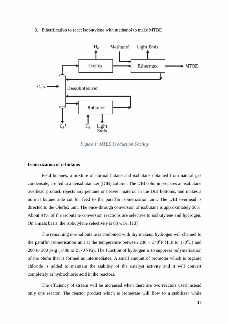
3. Etherification to react isobutylene with methanol to make MTBE
Figure 1: MTBE Production Facility
Isomerization of n-butane:
Field butanes, a mixture of normal butane and isobutane obtained from natural gas
condensate, are fed to a deisobutanizer (DIB) column. The DIB column prepares an isobutane
overhead product, rejects any pentane or heavier material in the DIB bottoms, and makes a
normal butane side cut for feed to the paraffin isomerization unit. The DIB overhead is
directed to the Oleflex unit. The once-through conversion of isobutane is approximately 50%.
About 91% of the isobutane conversion reactions are selective to isobutylene and hydrogen.
On a mass basis, the isobutylene selectivity is 88 wt%. [13]
The remaining normal butane is combined with dry makeup hydrogen will channel to
the paraffin isomerisation unit at the temperature between 230 – 340oF (110 to 170
oC) and
200 to 300 psig (1480 to 2170 kPa). The function of hydrogen is to suppress polymerization
of the olefin that is formed as intermediates. A small amount of promoter which is organic
chloride is added to maintain the stability of the catalyst activity and it will convert
completely as hydrochloric acid in the reactors.
The efficiency of stream will be increased when there are two reactors used instead
only one reactor. The reactor product which is isomerate will flow to a stabilizer while
18
hydrochloric acid will flow to the scrubber and the scrubber will remove the hydrochloric
acid from the light gases. The stabilized liquid product contains almost same amount of
composition mixture of n-butane and isboutane. The unconverted n-butane will be recycled
back to isomerization unit to convert it to isobutane in order to achieve nearly total
conversion of n-butane to isobutane. [14]
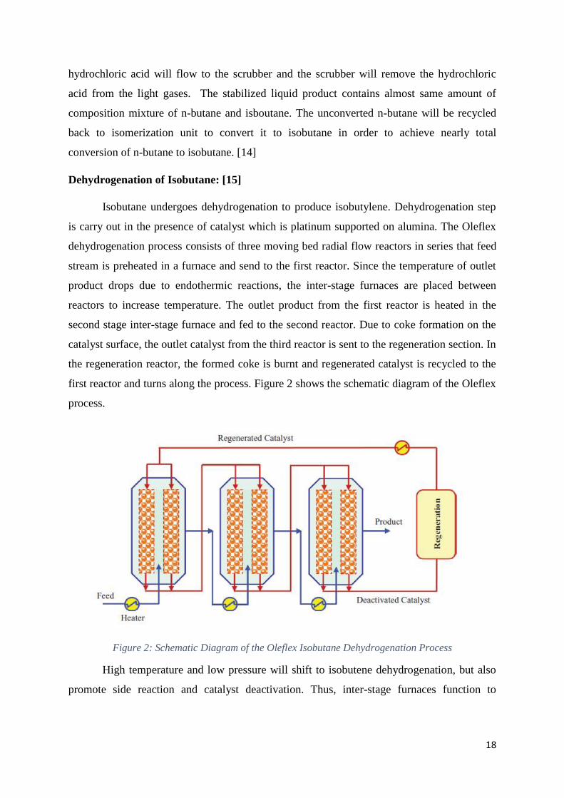
Dehydrogenation of Isobutane: [15]
Isobutane undergoes dehydrogenation to produce isobutylene. Dehydrogenation step
is carry out in the presence of catalyst which is platinum supported on alumina. The Oleflex
dehydrogenation process consists of three moving bed radial flow reactors in series that feed
stream is preheated in a furnace and send to the first reactor. Since the temperature of outlet
product drops due to endothermic reactions, the inter-stage furnaces are placed between
reactors to increase temperature. The outlet product from the first reactor is heated in the
second stage inter-stage furnace and fed to the second reactor. Due to coke formation on the
catalyst surface, the outlet catalyst from the third reactor is sent to the regeneration section. In
the regeneration reactor, the formed coke is burnt and regenerated catalyst is recycled to the
first reactor and turns along the process. Figure 2 shows the schematic diagram of the Oleflex
process.
Figure 2: Schematic Diagram of the Oleflex Isobutane Dehydrogenation Process
High temperature and low pressure will shift to isobutene dehydrogenation, but also
promote side reaction and catalyst deactivation. Thus, inter-stage furnaces function to
19
maintain the desired temperature required for dehydrogenation reaction. The equation below
shows the dehydrogenation of isobutane.
iC4H10 ↔ iC4H8 + H2
Isobutane ↔ Isobutene + Hydrogen
Besides, there are 3 possible side reactions that might occur during dehydrogenation of
isobutane.
1. Isobutane Cracking:
iC4H10+H2↔ C3H8 + CH4
Isobutane + Hydrogen ↔ Propane + Methane
2. Propane Dehydrogenation:
C3H8 ↔ H2 + C3H6
Propane ↔ Hydrogen + Propene
3. Coke Formation
iC4H8↔ 4C + 4H2
Isobutene ↔ Carbon + Hydrogen
Etherification Process:
The Ethermax process can be used to produce methyl tert- butyl ether (MTBE). This
process combines the Hüls fixed-bed etherification process with advanced RWD catalytic
distillation technology from Koch-Glitsch, Inc. The combined technology overcomes reaction
equilibrium limitations inherent in a conventional fixed-bed etherification process. The
Ethermax process reacts isobutylene over an acid resin in the presence of methanol to form
MTBE. The reaction chemistry and unit operating conditions are essentially the same as those
of a conventional ether process, such as the Hüls MTBE process, except that KataMax
packing has been added to increase the overall conversion. KataMax packing represents a
unique and proprietary approach to exposing a solid catalyst to a liquid stream inside a
distillation column. The reactive distillation zone of the RWD column uses KataMax packing
to overcome reaction equilibrium constraints by continuously fractionating the ether product
from unreacted feed components. As the ether product is distilled away, the reacting mixture
is no longer at equilibrium. Thus, fractionation in the presence of the catalyst promotes
20
additional conversion of the reactants. Isobutylene conversion of 99 for MTBE can be
achieved in this process. [16]
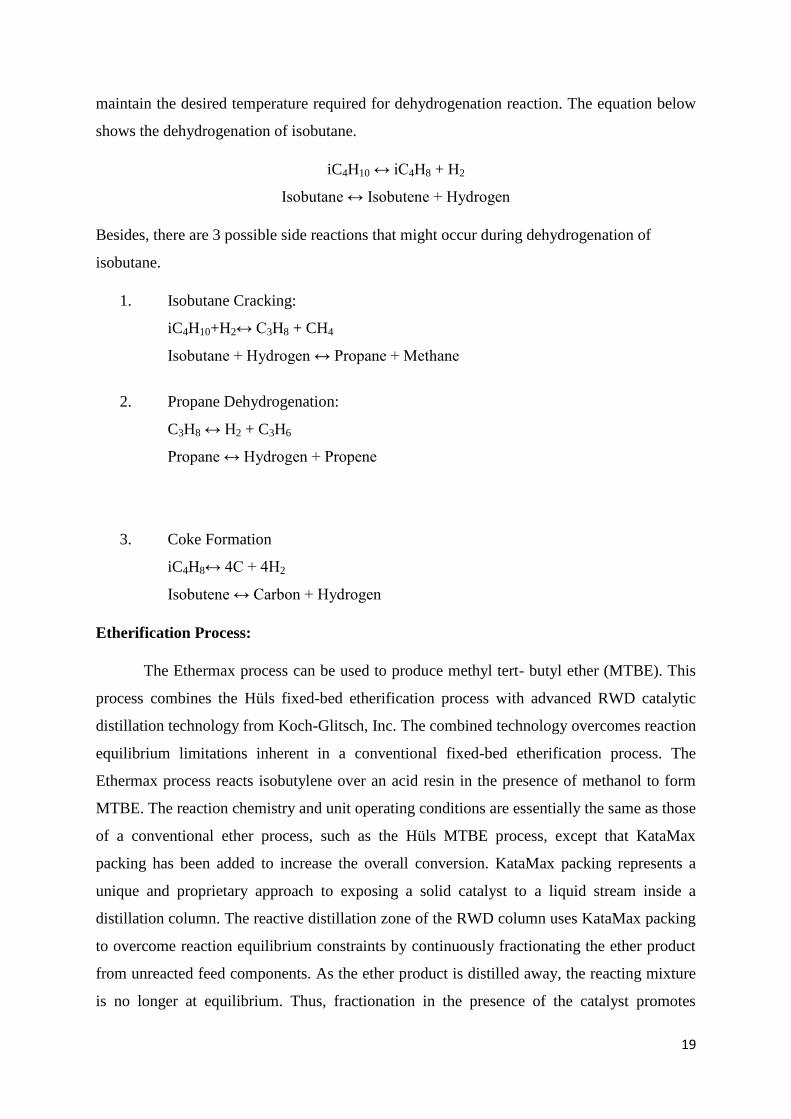
Figure 3 is a simplified flow diagram of the Ethermax process. Isobutylene and small
excess stoichiometric amount of methanol join a controlled quantity of recycle from the
reactor effluent and are cooled prior to entering the top of the primary reactor. The combined
feeds and recycle are all liquids. The resin catalyst in the primary reactor is a fixed bed of
small beads. The reactants flow down through the catalyst bed and exit the bottom of the
reactor. Effluent from the primary reactor contains MTBE, methanol and unreacted C4 olefins
and usually some C4paraffins, which were in the feed.
A significant amount of the effluent is cooled and recycled to control the reactor
temperature. The net effluent feeds a fractionator with a section containing catalyst. This is
Koch’s proprietary reaction with distillation (RWD) column. The catalyst section, located
above the feed entry, is simply structured packing with conventional MTBE resin catalyst
between the corrugated mesh plates. MTBE is withdrawn as the bottom product, and
unreacted methanol vapor and isobutylene vapor flow up into the catalyst reaction to be
converted to MTBE.
The advantages of an RWD column include essentially complete isoolefin
conversions. The excess methanol and unreacted hydrocarbons are withdrawn from the RWD
column reflux accumulator and fed to a methanol recovery tower. In this tower, the excess
methanol is extracted by contact with water. The resultant methanol-water mixture is distilled
to recover the methanol, which is then recycled to the primary reaction. [17]
Figure 3: A simplified flow diagram of the Ethermax process
21
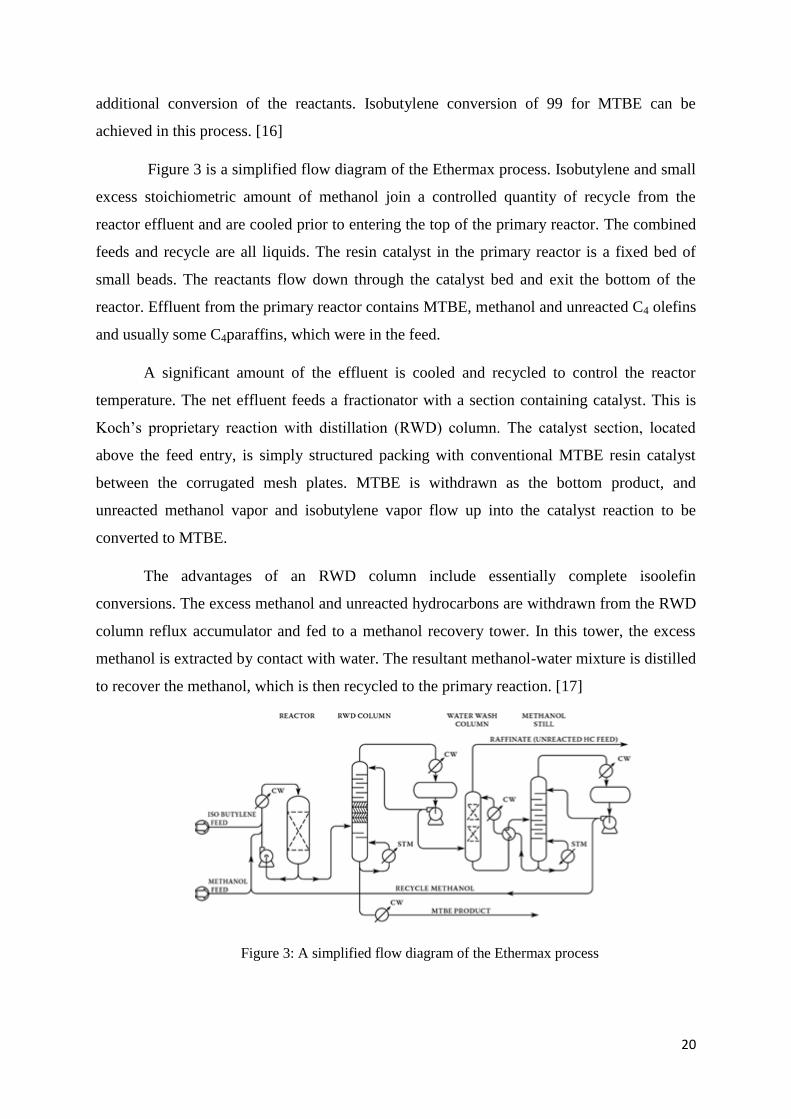
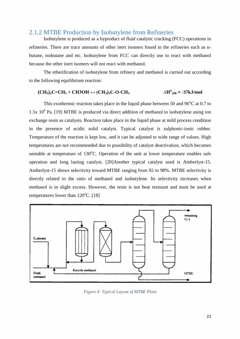
2.1.2 MTBE Production by Isobutylene from Refineries Isobutylene is produced as a byproduct of fluid catalytic cracking (FCC) operations in
refineries. There are trace amounts of other inert isomers found in the refineries such as n-
butane, isobutane and etc. Isobutylene from FCC can directly use to react with methanol
because the other inert isomers will not react with methanol.
The etherification of isobutylene from refinery and methanol is carried out according
to the following equilibrium reaction:
(CH3)2C=CH2 + CH3OH ↔ (CH3)3C-O-CH3 ∆Ho
298 ≈ -37kJ/mol
This exothermic reaction takes place in the liquid phase between 50 and 90oC at 0.7 to
1.5x 10⁶ Pa. [19] MTBE is produced via direct addition of methanol to isobutylene using ion
exchange resin as catalysts. Reaction takes place in the liquid phase at mild process condition
in the presence of acidic solid catalyst. Typical catalyst is sulphonic-ionic rubber.
Temperature of the reaction is kept low, and it can be adjusted to wide range of values. High
temperatures are not recommended due to possibility of catalyst deactivation, which becomes
unstable at temperature of 130oC. Operation of the unit at lower temperature enables safe
operation and long lasting catalyst. [20]Another typical catalyst used is Amberlyst-15.
Amberlyst-15 shows selectivity toward MTBE ranging from 92 to 98%. MTBE selectivity is
directly related to the ratio of methanol and isobutylene. Its selectivity increases when
methanol is in slight excess. However, the resin is not heat resistant and must be used at
temperatures lower than 120oC. [18]
Figure 4: Typical Layout of MTBE Plant
22
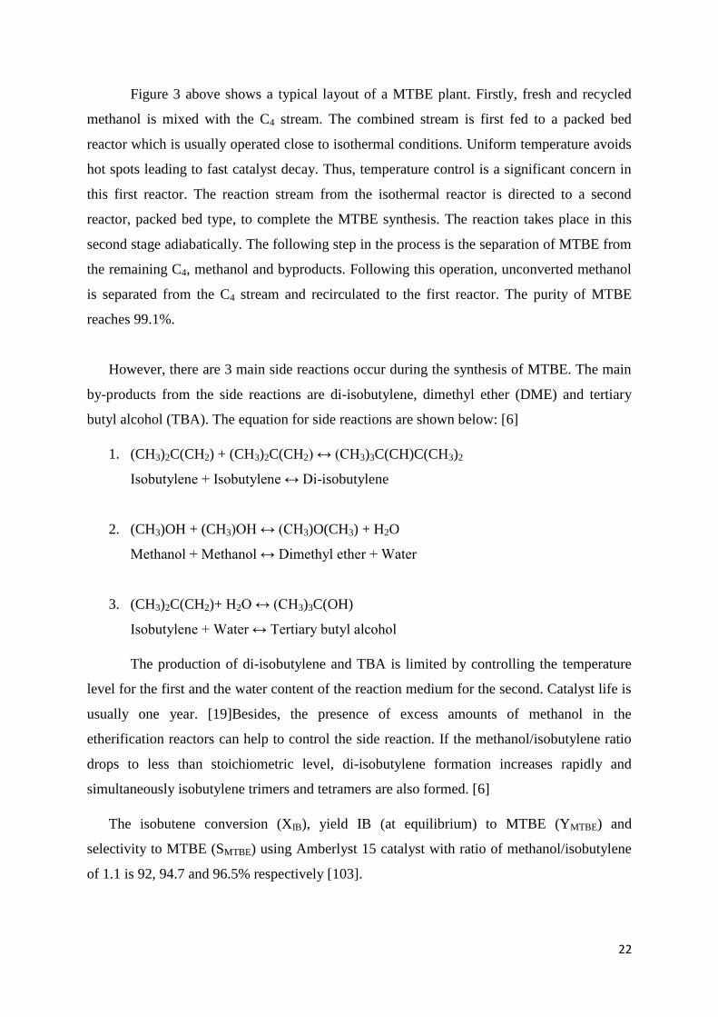
Figure 3 above shows a typical layout of a MTBE plant. Firstly, fresh and recycled
methanol is mixed with the C4 stream. The combined stream is first fed to a packed bed
reactor which is usually operated close to isothermal conditions. Uniform temperature avoids
hot spots leading to fast catalyst decay. Thus, temperature control is a significant concern in
this first reactor. The reaction stream from the isothermal reactor is directed to a second
reactor, packed bed type, to complete the MTBE synthesis. The reaction takes place in this
second stage adiabatically. The following step in the process is the separation of MTBE from
the remaining C4, methanol and byproducts. Following this operation, unconverted methanol
is separated from the C4 stream and recirculated to the first reactor. The purity of MTBE
reaches 99.1%.
However, there are 3 main side reactions occur during the synthesis of MTBE. The main
by-products from the side reactions are di-isobutylene, dimethyl ether (DME) and tertiary
butyl alcohol (TBA). The equation for side reactions are shown below: [6]
1. (CH3)2C(CH2) + (CH3)2C(CH2) ↔ (CH3)3C(CH)C(CH3)2
Isobutylene + Isobutylene ↔ Di-isobutylene
2. (CH3)OH + (CH3)OH ↔ (CH3)O(CH3) + H2O
Methanol + Methanol ↔ Dimethyl ether + Water
3. (CH3)2C(CH2)+ H2O ↔ (CH3)3C(OH)
Isobutylene + Water ↔ Tertiary butyl alcohol
The production of di-isobutylene and TBA is limited by controlling the temperature
level for the first and the water content of the reaction medium for the second. Catalyst life is
usually one year. [19]Besides, the presence of excess amounts of methanol in the
etherification reactors can help to control the side reaction. If the methanol/isobutylene ratio
drops to less than stoichiometric level, di-isobutylene formation increases rapidly and
simultaneously isobutylene trimers and tetramers are also formed. [6]
The isobutene conversion (XIB), yield IB (at equilibrium) to MTBE (YMTBE) and
selectivity to MTBE (SMTBE) using Amberlyst 15 catalyst with ratio of methanol/isobutylene
of 1.1 is 92, 94.7 and 96.5% respectively [103].
23
MTBE is recovered as the bottoms product of a distillation unit. The methanol-rich
C4 distillate is sent to the methanol-recovery section. Water is used to extract excess
methanol and recycle it back to process. The isobutylene-depleted C4 stream may be sent to a
raffinate stripper or to a moiseive-based unit to remove other oxygenates such as DME,
MTBE, methanol and tert-butanol. [21]
Etherification process:
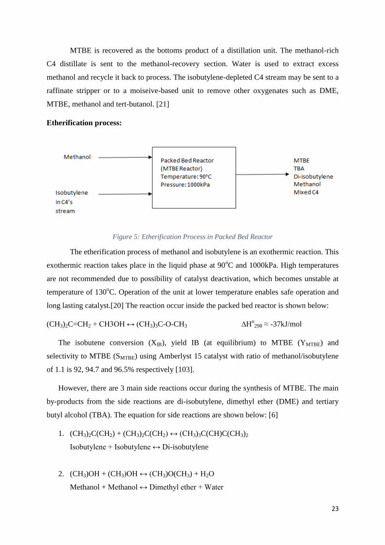
Figure 5: Etherification Process in Packed Bed Reactor
The etherification process of methanol and isobutylene is an exothermic reaction. This
exothermic reaction takes place in the liquid phase at 90oC and 1000kPa. High temperatures
are not recommended due to possibility of catalyst deactivation, which becomes unstable at
temperature of 130oC. Operation of the unit at lower temperature enables safe operation and
long lasting catalyst.[20] The reaction occur inside the packed bed reactor is shown below:
(CH3)2C=CH2 + CH3OH ↔ (CH3)3C-O-CH3 ∆Ho298 ≈ -37kJ/mol
The isobutene conversion (XIB), yield IB (at equilibrium) to MTBE (YMTBE) and
selectivity to MTBE (SMTBE) using Amberlyst 15 catalyst with ratio of methanol/isobutylene
of 1.1 is 92, 94.7 and 96.5% respectively [103].
However, there are 3 main side reactions occur during the synthesis of MTBE. The main
by-products from the side reactions are di-isobutylene, dimethyl ether (DME) and tertiary
butyl alcohol (TBA). The equation for side reactions are shown below: [6]
1. (CH3)2C(CH2) + (CH3)2C(CH2) ↔ (CH3)3C(CH)C(CH3)2
Isobutylene + Isobutylene ↔ Di-isobutylene
2. (CH3)OH + (CH3)OH ↔ (CH3)O(CH3) + H2O
Methanol + Methanol ↔ Dimethyl ether + Water
24
3. (CH3)2C(CH2)+ H2O ↔ (CH3)3C(OH)
Isobutylene + Water ↔ Tertiary butyl alcohol
However, there are no reported works on the selectivity of the side reaction during the
synthesis of MTBE from isobutylene and methanol. Several strategies have been used to
reduce the production of these undesirable by-products. First, the ratio of methanol and
isobutylene is kept above one to suppress the dimerization of butane. Reaction temperatures
below 100oC can diminish the formation of dimethyl ether. Finally, the pretreatment of the
feed stream which is removal of water can prevents the formation of TBA [104].
Liquid-liquid extraction process:
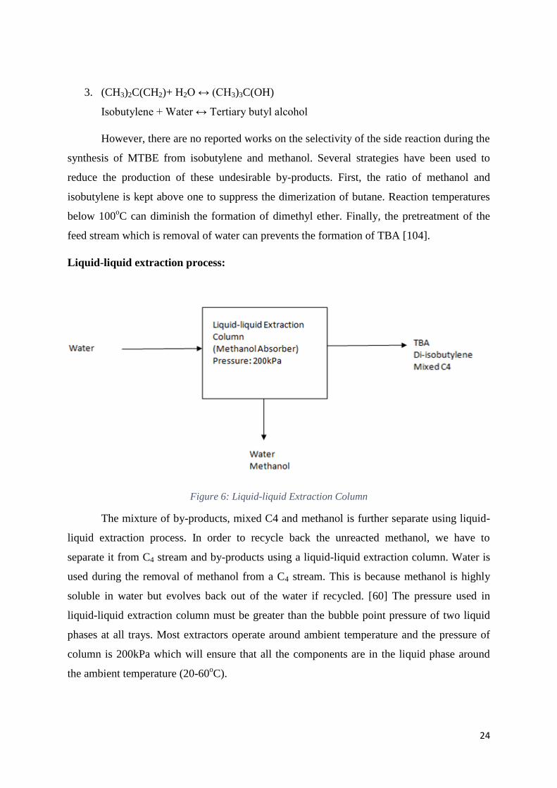
Figure 6: Liquid-liquid Extraction Column
The mixture of by-products, mixed C4 and methanol is further separate using liquid-
liquid extraction process. In order to recycle back the unreacted methanol, we have to
separate it from C4 stream and by-products using a liquid-liquid extraction column. Water is
used during the removal of methanol from a C4 stream. This is because methanol is highly
soluble in water but evolves back out of the water if recycled. [60] The pressure used in
liquid-liquid extraction column must be greater than the bubble point pressure of two liquid
phases at all trays. Most extractors operate around ambient temperature and the pressure of
column is 200kPa which will ensure that all the components are in the liquid phase around
the ambient temperature (20-60oC).
25
2.1.3 MTBE Production by Isobutylene from TBA: In this process, TBA is used to produce MTBE. TBA is produced in large quantities
from processes for producing propylene oxide from propylene. Propylene oxide is an organic
compound that is produced on a large scale industrially with its major application being its
use for the production of polyether for use in making polyurethane plastics and propylene
glycol. Tertiary butyl alcohol (TBA), a co-product of propylene oxide (PO), is produced by
PO manufacturers. Although it can be used directly as an oxygenate, it can also be used as a
raw material in the production of MTBE. Some of the PO manufacturers will also produce
MTBE starting from the co-product, TBA. They start with isobutane as a feedstock to
produce TBA and then, ultimately, MTBE, as part of the “PO/MTBE” manufacturing process
[22].
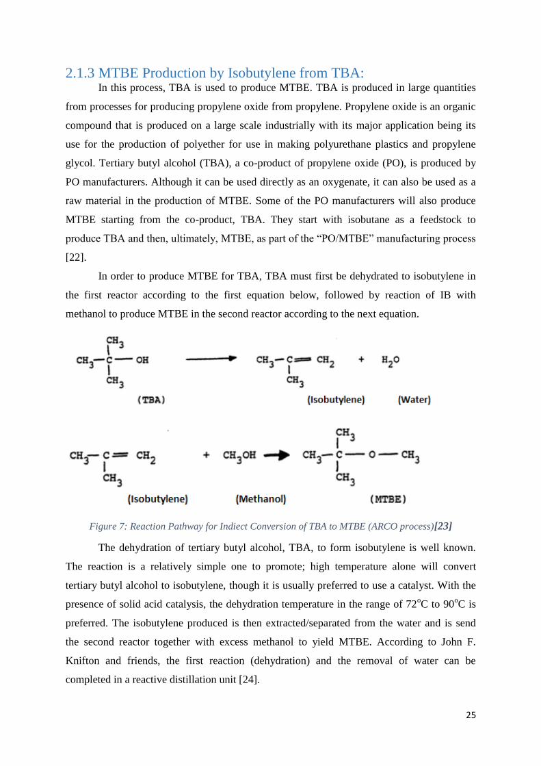
In order to produce MTBE for TBA, TBA must first be dehydrated to isobutylene in
the first reactor according to the first equation below, followed by reaction of IB with
methanol to produce MTBE in the second reactor according to the next equation.
Figure 7: Reaction Pathway for Indiect Conversion of TBA to MTBE (ARCO process)[23]
The dehydration of tertiary butyl alcohol, TBA, to form isobutylene is well known.
The reaction is a relatively simple one to promote; high temperature alone will convert
tertiary butyl alcohol to isobutylene, though it is usually preferred to use a catalyst. With the
presence of solid acid catalysis, the dehydration temperature in the range of 72oC to 90
oC is
preferred. The isobutylene produced is then extracted/separated from the water and is send
the second reactor together with excess methanol to yield MTBE. According to John F.
Knifton and friends, the first reaction (dehydration) and the removal of water can be
completed in a reactive distillation unit [24].
26
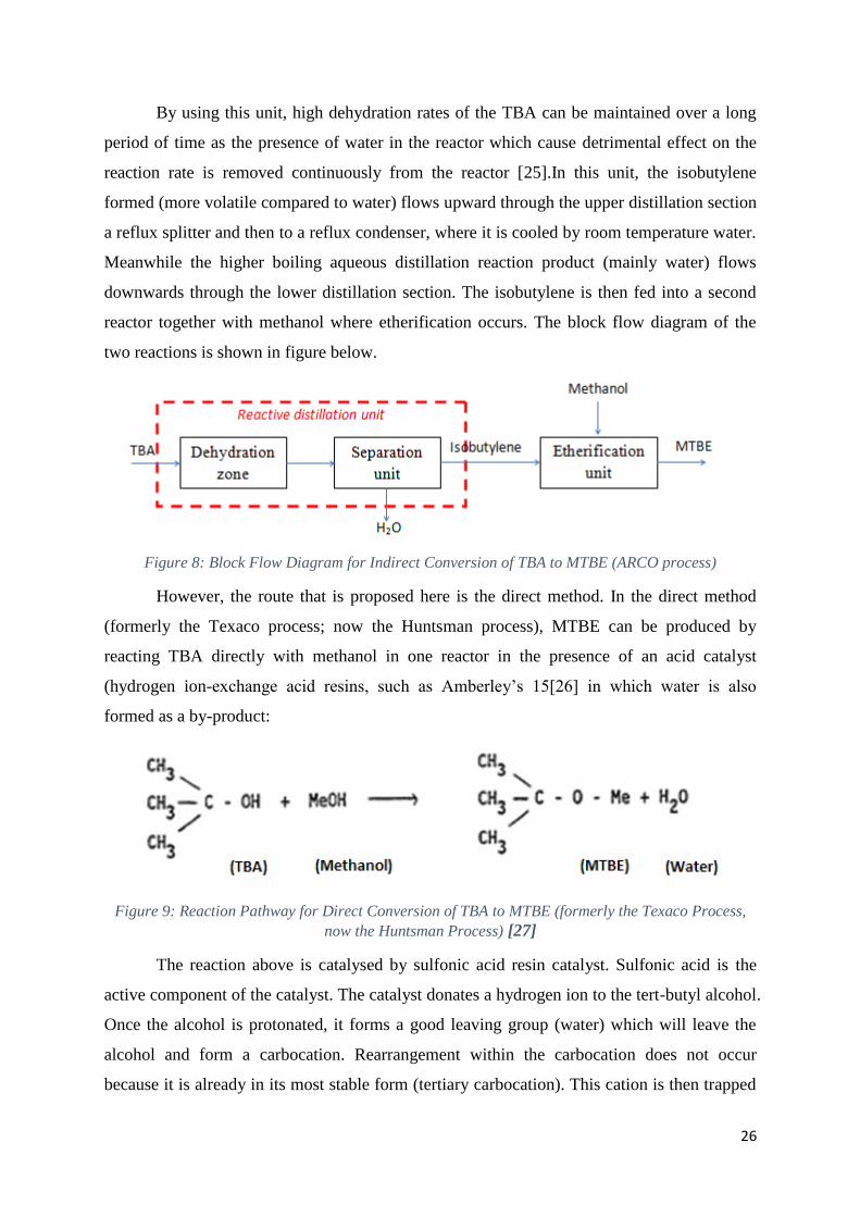
By using this unit, high dehydration rates of the TBA can be maintained over a long
period of time as the presence of water in the reactor which cause detrimental effect on the
reaction rate is removed continuously from the reactor [25].In this unit, the isobutylene
formed (more volatile compared to water) flows upward through the upper distillation section
a reflux splitter and then to a reflux condenser, where it is cooled by room temperature water.
Meanwhile the higher boiling aqueous distillation reaction product (mainly water) flows
downwards through the lower distillation section. The isobutylene is then fed into a second
reactor together with methanol where etherification occurs. The block flow diagram of the
two reactions is shown in figure below.
Figure 8: Block Flow Diagram for Indirect Conversion of TBA to MTBE (ARCO process)
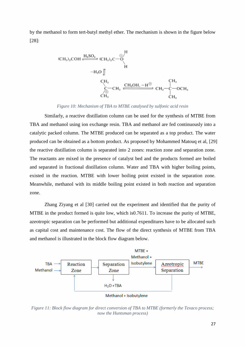
However, the route that is proposed here is the direct method. In the direct method
(formerly the Texaco process; now the Huntsman process), MTBE can be produced by
reacting TBA directly with methanol in one reactor in the presence of an acid catalyst
(hydrogen ion-exchange acid resins, such as Amberley’s 15[26] in which water is also
formed as a by-product:
Figure 9: Reaction Pathway for Direct Conversion of TBA to MTBE (formerly the Texaco Process,
now the Huntsman Process) [27]
The reaction above is catalysed by sulfonic acid resin catalyst. Sulfonic acid is the
active component of the catalyst. The catalyst donates a hydrogen ion to the tert-butyl alcohol.
Once the alcohol is protonated, it forms a good leaving group (water) which will leave the
alcohol and form a carbocation. Rearrangement within the carbocation does not occur
because it is already in its most stable form (tertiary carbocation). This cation is then trapped
27
by the methanol to form tert-butyl methyl ether. The mechanism is shown in the figure below
[28]:
Figure 10: Mechanism of TBA to MTBE catalysed by sulfonic acid resin
Similarly, a reactive distillation column can be used for the synthesis of MTBE from
TBA and methanol using ion exchange resin. TBA and methanol are fed continuously into a
catalytic packed column. The MTBE produced can be separated as a top product. The water
produced can be obtained as a bottom product. As proposed by Mohammed Matouq et al, [29]
the reactive distillation column is separated into 2 zones: reaction zone and separation zone.
The reactants are mixed in the presence of catalyst bed and the products formed are boiled
and separated in fractional distillation column. Water and TBA with higher boiling points,
existed in the reaction. MTBE with lower boiling point existed in the separation zone.
Meanwhile, methanol with its middle boiling point existed in both reaction and separation
zone.
Zhang Ziyang et al [30] carried out the experiment and identified that the purity of
MTBE in the product formed is quite low, which is0.7611. To increase the purity of MTBE,
azeotropic separation can be performed but additional expenditures have to be allocated such
as capital cost and maintenance cost. The flow of the direct synthesis of MTBE from TBA
and methanol is illustrated in the block flow diagram below.
Figure 11: Block flow diagram for direct conversion of TBA to MTBE (formerly the Texaco process;
now the Huntsman process)
22
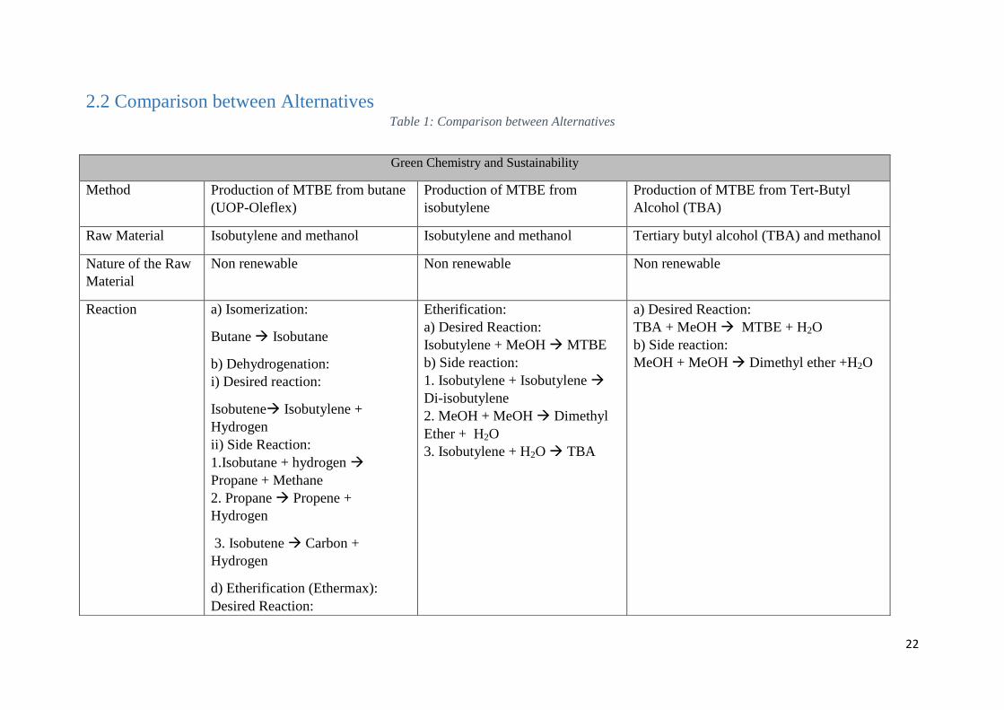
2.2 Comparison between Alternatives Table 1: Comparison between Alternatives
Green Chemistry and Sustainability
Method Production of MTBE from butane
(UOP-Oleflex)
Production of MTBE from
isobutylene
Production of MTBE from Tert-Butyl
Alcohol (TBA)
Raw Material Isobutylene and methanol Isobutylene and methanol Tertiary butyl alcohol (TBA) and methanol
Nature of the Raw
Material
Non renewable Non renewable Non renewable
Reaction a) Isomerization:
Butane Isobutane
b) Dehydrogenation:
i) Desired reaction:
Isobutene Isobutylene +
Hydrogen
ii) Side Reaction:
1.Isobutane + hydrogen
Propane + Methane
2. Propane Propene +
Hydrogen
3. Isobutene Carbon +
Hydrogen
d) Etherification (Ethermax):
Desired Reaction:
Etherification:
a) Desired Reaction:
Isobutylene + MeOH MTBE
b) Side reaction:
1. Isobutylene + Isobutylene
Di-isobutylene
2. MeOH + MeOH Dimethyl
Ether + H2O
3. Isobutylene + H2O TBA
a) Desired Reaction:
TBA + MeOH MTBE + H2O
b) Side reaction:
MeOH + MeOH Dimethyl ether +H2O
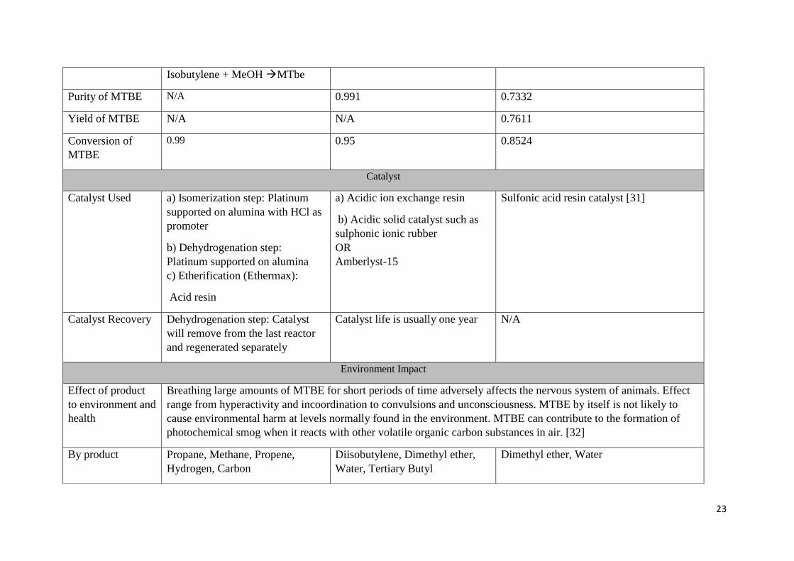
23
Isobutylene + MeOH MTbe
Purity of MTBE N/A 0.991 0.7332
Yield of MTBE N/A N/A 0.7611
Conversion of
MTBE
0.99 0.95 0.8524
Catalyst
Catalyst Used a) Isomerization step: Platinum
supported on alumina with HCl as
promoter
b) Dehydrogenation step:
Platinum supported on alumina
c) Etherification (Ethermax):
Acid resin
a) Acidic ion exchange resin
b) Acidic solid catalyst such as
sulphonic ionic rubber
OR
Amberlyst-15
Sulfonic acid resin catalyst [31]
Catalyst Recovery Dehydrogenation step: Catalyst
will remove from the last reactor
and regenerated separately
Catalyst life is usually one year N/A
Environment Impact
Effect of product
to environment and
health
Breathing large amounts of MTBE for short periods of time adversely affects the nervous system of animals. Effect
range from hyperactivity and incoordination to convulsions and unconsciousness. MTBE by itself is not likely to
cause environmental harm at levels normally found in the environment. MTBE can contribute to the formation of
photochemical smog when it reacts with other volatile organic carbon substances in air. [32]
By product Propane, Methane, Propene,
Hydrogen, Carbon
Diisobutylene, Dimethyl ether,
Water, Tertiary Butyl
Dimethyl ether, Water
24
alcohol,Untreated Methanol
Effect of by-
product to
environment
Methane able to absorb infrared
radiation at a rate 21 times greater
than greenhouse gas CO2. [33]
1. Diisobutylene: very toxic to
aquatic life with long lasting
effects. [34]
2. t-butyl alcohol:
3. dimethyl ether: not expected to
be persistent in the environment
and is not bio accumulative [35]
Dimethyl ether: not expected to be
persistent in the environment and is not bio
accumulative.
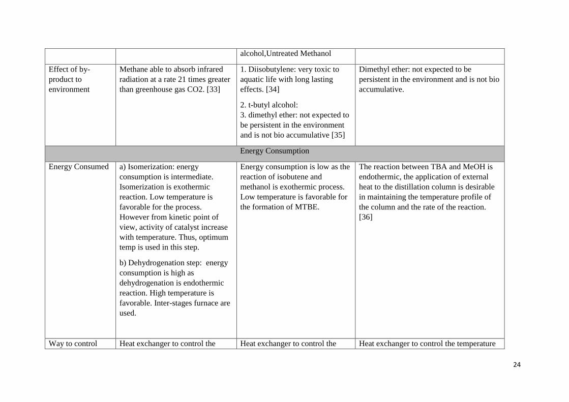
Energy Consumption
Energy Consumed a) Isomerization: energy
consumption is intermediate.
Isomerization is exothermic
reaction. Low temperature is
favorable for the process.
However from kinetic point of
view, activity of catalyst increase
with temperature. Thus, optimum
temp is used in this step.
b) Dehydrogenation step: energy
consumption is high as
dehydrogenation is endothermic
reaction. High temperature is
favorable. Inter-stages furnace are
used.
Energy consumption is low as the
reaction of isobutene and
methanol is exothermic process.
Low temperature is favorable for
the formation of MTBE.
The reaction between TBA and MeOH is
endothermic, the application of external
heat to the distillation column is desirable
in maintaining the temperature profile of
the column and the rate of the reaction.
[36]
Way to control Heat exchanger to control the Heat exchanger to control the Heat exchanger to control the temperature
25
energy
consumption
temperature of isomerization unit temperature of packed bed reactor of column.
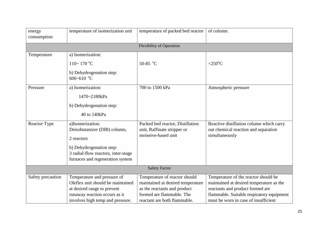
Flexibility of Operation
Temperature a) Isomerization:
110~ 170 oC
b) Dehydrogenation step:
600~610 oC
50-85 oC
<250oC
Pressure a) Isomerization:
1470~2180kPa
b) Dehydrogenation step:
40 to 140kPa
700 to 1500 kPa Atmospheric pressure
Reactor Type a)Isomerization:
Deisobutanizer (DIB) column,
2 reactors
b) Dehydrogenation step:
3 radial-flow reactors, inter-stage
furnaces and regeneration system
Packed bed reactor, Distillation
unit, Raffinate stripper or
moiseive-based unit
Reactive distillation column which carry
out chemical reaction and separation
simultaneously
Safety Factor
Safety precaution Temperature and pressure of
Oleflex unit should be maintained
at desired range to prevent
runaway reaction occurs as it
involves high temp and pressure.
Temperature of reactor should
maintained at desired temperature
as the reactants and product
formed are flammable. The
reactant are both flammable.
Temperature of the reactor should be
maintained at desired temperature as the
reactants and product formed are
flammable. Suitable respiratory equipment
must be worn in case of insufficient
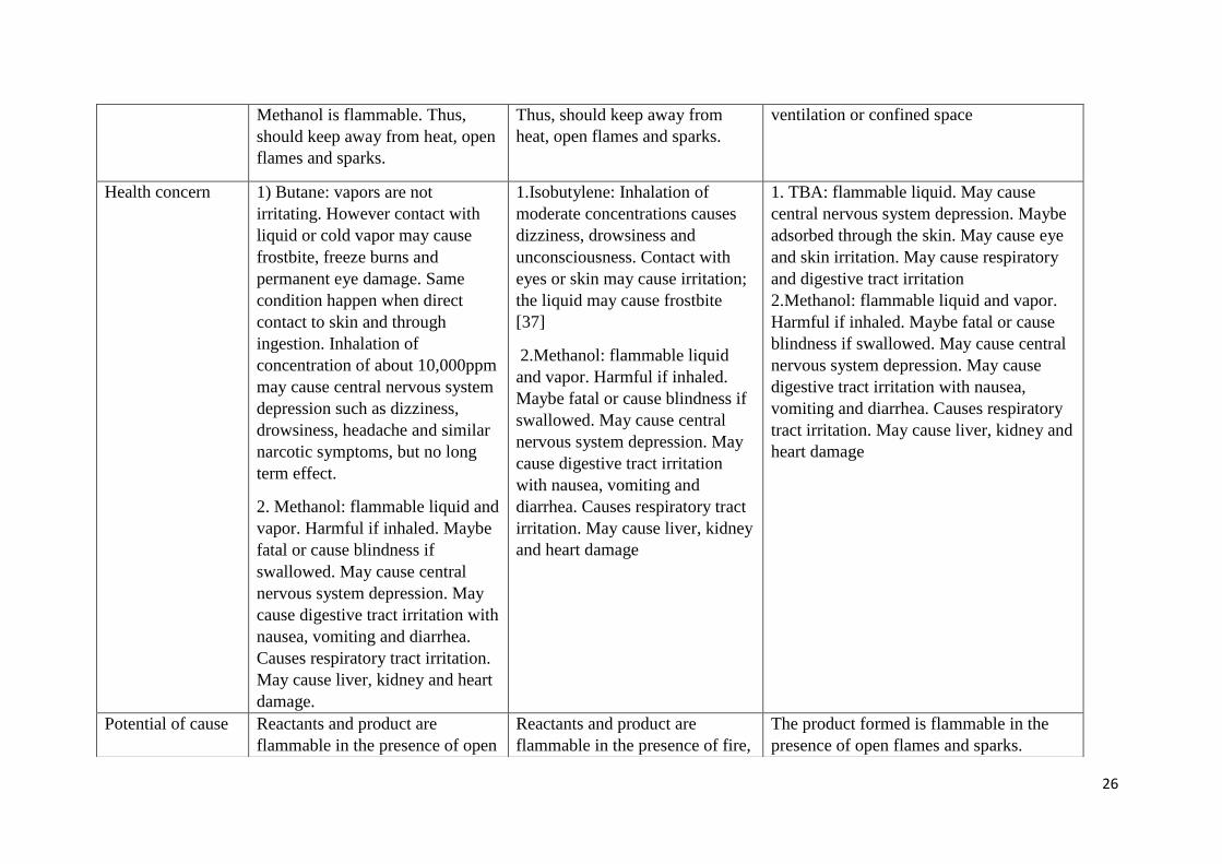
26
Methanol is flammable. Thus,
should keep away from heat, open
flames and sparks.
Thus, should keep away from
heat, open flames and sparks.
ventilation or confined space
Health concern 1) Butane: vapors are not
irritating. However contact with
liquid or cold vapor may cause
frostbite, freeze burns and
permanent eye damage. Same
condition happen when direct
contact to skin and through
ingestion. Inhalation of
concentration of about 10,000ppm
may cause central nervous system
depression such as dizziness,
drowsiness, headache and similar
narcotic symptoms, but no long
term effect.
2. Methanol: flammable liquid and
vapor. Harmful if inhaled. Maybe
fatal or cause blindness if
swallowed. May cause central
nervous system depression. May
cause digestive tract irritation with
nausea, vomiting and diarrhea.
Causes respiratory tract irritation.
May cause liver, kidney and heart
damage.
1.Isobutylene: Inhalation of
moderate concentrations causes
dizziness, drowsiness and
unconsciousness. Contact with
eyes or skin may cause irritation;
the liquid may cause frostbite
[37]
2.Methanol: flammable liquid
and vapor. Harmful if inhaled.
Maybe fatal or cause blindness if
swallowed. May cause central
nervous system depression. May
cause digestive tract irritation
with nausea, vomiting and
diarrhea. Causes respiratory tract
irritation. May cause liver, kidney
and heart damage
1. TBA: flammable liquid. May cause
central nervous system depression. Maybe
adsorbed through the skin. May cause eye
and skin irritation. May cause respiratory
and digestive tract irritation
2.Methanol: flammable liquid and vapor.
Harmful if inhaled. Maybe fatal or cause
blindness if swallowed. May cause central
nervous system depression. May cause
digestive tract irritation with nausea,
vomiting and diarrhea. Causes respiratory
tract irritation. May cause liver, kidney and
heart damage
Potential of cause Reactants and product are
flammable in the presence of open
Reactants and product are
flammable in the presence of fire,
The product formed is flammable in the
presence of open flames and sparks.
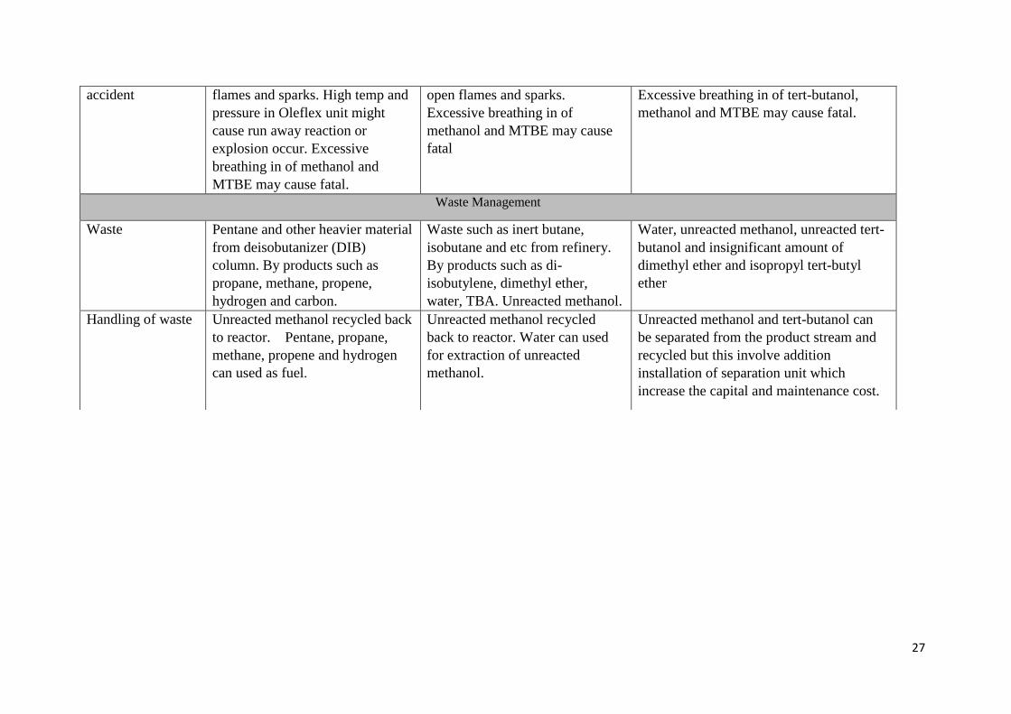
27
accident flames and sparks. High temp and
pressure in Oleflex unit might
cause run away reaction or
explosion occur. Excessive
breathing in of methanol and
MTBE may cause fatal.
open flames and sparks.
Excessive breathing in of
methanol and MTBE may cause
fatal
Excessive breathing in of tert-butanol,
methanol and MTBE may cause fatal.
Waste Management
Waste Pentane and other heavier material
from deisobutanizer (DIB)
column. By products such as
propane, methane, propene,
hydrogen and carbon.
Waste such as inert butane,
isobutane and etc from refinery.
By products such as di-
isobutylene, dimethyl ether,
water, TBA. Unreacted methanol.
Water, unreacted methanol, unreacted tert-
butanol and insignificant amount of
dimethyl ether and isopropyl tert-butyl
ether
Handling of waste Unreacted methanol recycled back
to reactor. Pentane, propane,
methane, propene and hydrogen
can used as fuel.
Unreacted methanol recycled
back to reactor. Water can used
for extraction of unreacted
methanol.
Unreacted methanol and tert-butanol can
be separated from the product stream and
recycled but this involve addition
installation of separation unit which
increase the capital and maintenance cost.
31
2.3 Choice of Process As shown in table above, the three alternative ways to produce MTBE have been
discussed in terms of green chemistry and sustainability, environmental impact, energy
consumption, flexibility of operation and safety factors and waste management. In order to
choose the most suitable and feasible process alternative for our plant design, the advantages
and disadvantages of each aspect have been taken into account and thorough considerations.
There are 3 alternative ways to produce MTBE which has shown as below:
Method 1: MTBE production from n-butane
Method 2: MTBE production from isobutylene
Method 3: MTBE production from tertiary butyl alcohol (TBA)
Among the alternatives of the process suggested, the direct synthesis of MTBE from
isobutylene and methanol is the most applicable route path since it has the several advantages
among other routes. It will further discuss on several aspects as shown below.
2.3.1 Safety and Health Issues: Safety and health issues are the most crucial issues that must be considered when
selecting the material that being used in the plants. This is because the safety and health
issues not only covered the workers but also to the surrounding residential areas.
Firstly, we analyze the safety and health issues from the aspect of temperature of the
process. Desired temperature should be maintained throughout the process to prevent run
away reaction occurred. For method 1, there are 3 basic steps (isomerization,
dehydrogenation and etherification) involved in order to produce MTBE. Isomerization and
etherification (Ethermax) process are exothermic process. Thus, low temperature is favorable
in these two processes. In isomerization process, the desired temperature is 110 to 170oC.
While for etherification process, the desired temperature is 50 to 85oC. However, high
temperature is required for dehydrogenation process which is 600 to 610oC. This is because
dehydrogenation process is endothermic reaction. High temperature is favorable for the
formation of product.
For method 2, it only involve exothermic reaction. The desired temperature is 50 to
85oC. On the other hands, for method 3, it involved both exothermic and endothermic
reaction (dehydration and etherification). TBA dehydration to isobutylene is an endothermic
32
reaction. Thus, high temperature (<250oC) is favorable for the process. Whereas
etherification is exothermic reaction, low temperature of 50 to 85oC is required.
Next, we will analyze the safety and health issues from the aspect of pressure of the
process. Same as temperature, pressure is needed to maintain within the desired range. High
pressure might cause rupture of reactor or even explosion occur. In method 1, high pressure is
involved in isomerization step which is 1470 to 2180kPa. Besides, moderate pressure is used
in both dehydrogenation and etherification process. On the other hands, moderate pressure
which is 700 to 1500kPa is required for the etherification process. Lastly, atmospheric
pressure is required in method 3 which is the lowest pressure required compared to the others
two methods.
From the aspect of raw material, three methods use different raw materials which are
butane, isobutylene and TBA in order to produce MTBE. From the aspect of fire hazard, all
the raw materials are highly flammable. Hence, they must keep away from heat, sparks, open
flames or hot surfaces. From the aspect of health hazard, high exposure to butane will causes
drowsiness but no other evidence of systemic effect. On the other hands, inhalation of
moderate concentration of isobutylene will cause dizziness, drowsiness and unconsciousness.
Besides, contact with eyes or skin may cause irritation; the liquid may cause frostbite. While
for TBA, its vapor is narcotic in action and irritating to respiratory passages and its liquid is
irritating to skin and eyes. [37] In addition, among the three raw materials, TBA has been
classified as hazardous under Global Harmonized System of Classification and Labeling of
Chemicals (GHS) for its health effects.[38] Thus, extra careful is needed when handle with
TBA compared to isobutylene and butane.
Thus, we can conclude that method 2 is more applicable route path from the aspect of
safety and health issues. This is because reaction path in method 2 require low temperature
and moderate pressure. Besides, the raw material used in method 2 is not the most hazardous
compared to TBA used in method 3.
2.3.2 Environmental Issues: Generally, all of raw materials used are non-renewable sources. Besides, the product
itself which is MTBE will bring some environmental issues. Breathing large amounts of
MTBE for short periods of time adversely affects the nervous system of animals. Its effect
range from hyperactivity and incoordination to convulsions and unconsciousness. MTBE can
contribute to the formation of photochemical smog when it reacts with other volatile organic
33
carbon substances in air. [32]Thus, comparison between the by-products from the three
alternative route paths is our main focus.
For method 1, there are several by-products produced. Most of the by-products come
from the dehydrogenation process. One of the by-products is methane. Methane able to
absorb infrared radiation at a rate of 21 times greater than greenhouse gas, CO2. Thus, if the
by-product is not handle carefully and release to the atmosphere, it will lead to greenhouse
phenomena. Same as method 1, there are also several by-products formed through method 2.
One of the by-products which is di-isobutylene is very toxic to aquatic life with long lasting
effects. Thus, it has to handle carefully before it discharges from the reactor. Lastly, for
method 3, only two type of by-products produced which is water and dimethyl ether. Water
basically is not harmful to the environment. On the other hands, dimethyl ether is extremely
flammable and may form potentially explosive mixtures with air. Thus, we should not release
it to surrounding environment to prevent soil and water pollution.
All these route paths will produce by-product that might causes environmental issues
if mishandling them. However, method 3 only produces two kinds of by-products which is
water and dimethyl ether. Thus, the probability of mishandling of by-product is lower
compared to others two methods as method 1 and 2 have more by-products to handle with. In
conclusion, method 3 is more applicable route path in the aspect of environmental issues.
2.3.3 Public Issues: In August 1995, the City of Santa Monica discovered MTBE in drinking water supply
wells at its Charnock Wellfield. By 1996, persistent and increasing levels of MTBE at
concentrations as high as 600μg/L caused all of the Charnock Wellfield supply wells to be
shut down. Several public supply wells in South Lake Tahoe were found to be impacted by
MTBE. In 2001, the South Tahoe Public Utility District took 12 of the District’s 34 drinking
water wells off-line due to the detection or nearby presence of MTBE. In Glennville,
California, MTBE was detected in drinking water at some of the highest levels of MTBE ever
recorded. One well tested at 20,000 parts per billion. As of November 2009, MTBE had been
detected in 27 of approximately 4800 active and standby public groundwater sources at
concentrations greater than the SMCL (secondary maximum contaminant level) of 5.0μg/L.
MTBE was detected above the MCL (maximum contaminant level) of 13μg/L in 9 of those
active and standby public groundwater sources, and has also been detected in significant
concentrations in domestic and in small water system wells in many parts of the state. [39]
34
From the history of occurrence stated above, it shows that contamination of water
sources by MTBE is one of the serious public issues caused by MTBE plant. Fairly small
amounts of MTBE in water can give it an unpleasant taste and odor, making the water
undrinkable. MTBE also does not break down (biodegrade) easily. As a result, it is harder to
clean up once contamination occurs. [40]
For method 1, it involves 3 basic steps to produce MTBE. The plant for production of
MTBE can considered quite large compared to method 2 which only required one basic step.
More piping system and reactors involved in method 1 compared to method 2. Extra by
products and reactions have to take care compared to method 2. Thus, it will increase the
probability of leakage of MTBE to environment. For method 3, it involved the dehydration of
TBA and water is produced together with MTBE. Separation process is required to segregate
MTBE from water. Besides, necessary treatment is required for water before it discharge to
the environment in order to ensure water is free of MTBE. Thus, method 3 has the highest
probability to cause contamination of water sources if treatment of by-product which is water
is not carry out well.
In conclusion, method 2 is more applicable route path in the aspect of public issues.
This is because it only involved one basic step. Thus, it is easier to handle compared to
method 1 and 3.
2.3.4 Flexibility and Controllability:
In terms of the availability of the feedstock, Method 1 that use butane as their raw
material are abundant in many parts of the world. Similarly, the feedstock (C4 olefins mixture)
of the Method 2 is highly abundant in all around the world as well. There are a lot of
Refinery/Petrochemical Plants in the world for example Saudi Arabia, Venezuela and China
that can supply the demand of the feedstock to our plant. Thus, if the supply of the feedstock
is less in Malaysia, it is not a problem for us to get the feedstock from other countries.
However, tert-butyl alcohol (TBA) that is obtained as a side product from the propylene
oxide (PO) manufacturing plant. Hence, its source is highly dependent on the production of
PO. Also, the price of TBA is also slightly higher than isobutylene. [41] Hence, Method 2 is
more attractive compared to other alternatives for the production of MTBE in terms of
flexibility of feedstock.
35
For Method 1, there are 2 reactions that require two difference temperature and
pressure range for the reactions to occur. The desired temperature that is required to yield
MTBE in the second reaction is between 600oC and 610
oC, which is the highest compared to
the other methods. In addition, this narrow 10oC range and presence of two desired
temperature range for two different reactions have actually increased the difficulty and
complexity in controlling the reaction. Similarly, the pressure that required to promote the
isomerization in Method 1 is as high as 2180kPa. Meanwhile, Method 2 has the lowest
temperature (50oC-85
oC) condition and wider range for production of MTBE. The required
pressure is intermediate which is about 700kPa to 1500kPa.For method 3, the optimum
temperature for the reaction to occur can reach as high as 250oC and the reaction can occur
under atmospheric pressure. When comparing these three methods, Method 2 is still the best
choice temperature-wise, and when it is studied from the point of pressure, it is placed as
second after Method 3.
For controllability, Method 2 is the best as alternative and technology. Method 2 is
well established and is less complex compared to the other MTBE production plants, so the
process can be easily controlled. Other methods are more complicated such as Method 1
which requires dehydrogenation process before the MTBE can be formed by etherification
process. In other words, less unit operation is used compared to other alternatives routes, so
much easy to control. When the number of unit operations is less, the amount of energy
needed to operate the plant also will remain low. Based on the analysis, Method 2 is the
alternatives that give the most desired condition in terms of flexibility and controllability.
Thus, Method 2 is chosen as the route to produce MTBE.
2.3.5 Economic Indicators and Market Background Analysis: One of the raw materials used in three of the methods are same. Methanol is the
common feedstock that is required to produce MTBE no matter which route is chosen. In all
the three routes, pure methanol is obtained from refinery.
Butane comes from natural gas. It is derived from fossil fuel, created over the course
of millions of years by a complex process deep inside the earth from the remains of plants,
animals, and numerous microorganisms. [42]The butane that is used in Method 1 is obtained
from refineries. The raw material that is required for Method 2 is C4 olefin mixture, which
contains isobutylene is obtained from the petrochemical refineries. Malaysia is the second-
largest oil producer in Southeast Asia [43], and has the fifth largest oil reserves in the Asia
36
Pacific region. [44] Thus, there are a lot of oil refineries all around the Malaysia that make
Malaysia able to produce 642,700 barrel of oil per day in 2012[45]. Even all the oil refineries
in Malaysia do not want to supply their C4 stream product to our plant, we still can buy
isobutylene from overseas (i.e. China). According to Honeywell’s UOP base in China, there
are currently five C4 Oleflex units in operation, producing nearly 2 million metric tons of
isobutylene annually [46]. This is a large production rate so it would not be a problem in
getting the raw material we wanted for Method 2. For Method 3, the raw material TBA which
is obtained from propylene oxide producer is not feasible because there is no propylene oxide
plant in Malaysia.
In term of raw material price, butane is the cheapest compared to isobutylene and
TBA. However, Method 1 which is highly intensive because it consists of more unit
operation compared with Method 2 and Method 3. According to the official webpage of the
world's largest petrochemical market information provider, ICIS, the price of TBA is higher
than isobutylene, thus it is preferable to buy isobutylene instead of TBA. In addition, if
Method 3 is chosen, in order to get a sufficient amount of TBA, we probably have to buy it
from the largest producer of propylene oxide which is situated at United States. [47] Due to
the longer distance compared to China, this will subsequently increase the transportation cost
of raw material.
In terms of global demand, Argus DeWitt claimed that MTBE demand has increased
in the past few years driven by cleaner fuel requirements in China and increased gasoline
consumption in Asia, Americas, and the Middle East.Argus is a leading provider of data on
prices and fundamentals, news, analysis, consultancy services and conferences for the global
crude, oil products, LPG, natural gas, electricity, coal, emissions, bioenergy, fertilizer,
petrochemical, metals and transportation industries. According to Argus DeWitt 2015 Fuels
and Oxygenates Annual report [48], MTBE demand is expected to increase steadily in the
years to come but global operating rates will weaken as China overbuilds MTBE capacity.
Figure below shows the history and projections of global MTBE supply and demand from
2010 to 2020.
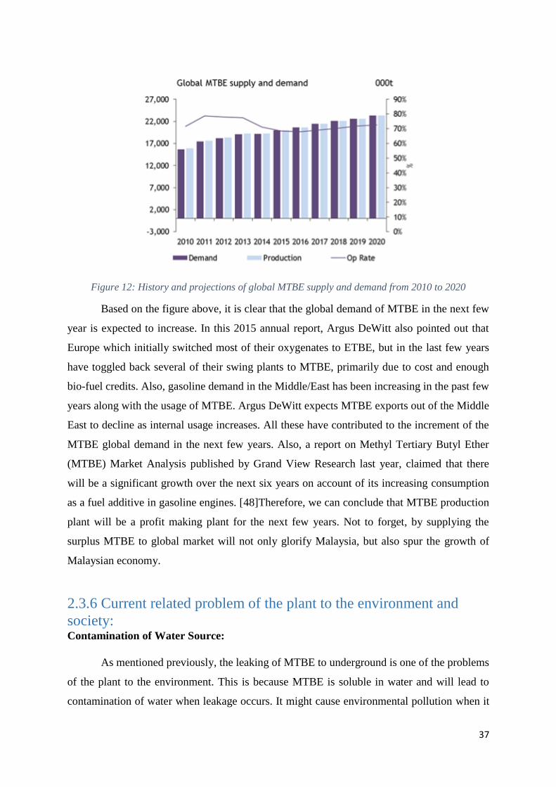
37
Figure 12: History and projections of global MTBE supply and demand from 2010 to 2020
Based on the figure above, it is clear that the global demand of MTBE in the next few
year is expected to increase. In this 2015 annual report, Argus DeWitt also pointed out that
Europe which initially switched most of their oxygenates to ETBE, but in the last few years
have toggled back several of their swing plants to MTBE, primarily due to cost and enough
bio-fuel credits. Also, gasoline demand in the Middle/East has been increasing in the past few
years along with the usage of MTBE. Argus DeWitt expects MTBE exports out of the Middle
East to decline as internal usage increases. All these have contributed to the increment of the
MTBE global demand in the next few years. Also, a report on Methyl Tertiary Butyl Ether
(MTBE) Market Analysis published by Grand View Research last year, claimed that there
will be a significant growth over the next six years on account of its increasing consumption
as a fuel additive in gasoline engines. [48]Therefore, we can conclude that MTBE production
plant will be a profit making plant for the next few years. Not to forget, by supplying the
surplus MTBE to global market will not only glorify Malaysia, but also spur the growth of
Malaysian economy.
2.3.6 Current related problem of the plant to the environment and
society: Contamination of Water Source:
As mentioned previously, the leaking of MTBE to underground is one of the problems
of the plant to the environment. This is because MTBE is soluble in water and will lead to
contamination of water when leakage occurs. It might cause environmental pollution when it
38
leak to river or lake. Besides, it will cause problems to society as it contaminates the drinking
water source. The recent case of contamination of water source occurred in South Lake
Tahoe. Several public supply wells were found to be impacted by MTBE. In 2001, the South
Tahoe Public Utility District took 12 of the District’s 34 drinking water wells off-line due to
the detection or nearby presence of MTBE. In Glennville, California, MTBE was detected in
drinking water at some of the highest levels of MTBE ever recorded. One well tested at
20,000 parts per billion. As of November 2009, MTBE had been detected in 27 of
approximately 4800 active and standby public groundwater sources at concentrations greater
than the SMCL (secondary maximum contaminant level) of 5.0μg/L. MTBE was detected
above the MCL (maximum contaminant level) of 13μg/L in 9 of those active and standby
public groundwater sources, and has also been detected in significant concentrations in
domestic and in small water system wells in many parts of the state. [39]
Fire Incident:
As we know, MTBE is extremely flammable with a high vapor pressure. It is use only
with good ventilation and avoids all ignition sources. [1] The recent explosion and fire
incident occurred at a Huntsman Petrochemical Corp. plant in Port Neches, Tex., near the
Louisiana border. According to board investigators, the fire occurred as works prepared a
process pipe for scheduled maintenance within 27 000 b/d that produces MTBE. The plant
personnel did not know at the time that the pipe contained residual feedstock chemicals said
by CBS officials. Workers directed steam through the pipe and inadvertently caused the
residual chemical inside to overheat and decompose as part of the shutdown. According to
investors, the pipe was ruptured due to accumulating of pressure and releasing a flammable
vapour cloud then ignited. Two workers were sent to the hospital with second degree burns
and caused minor injuries to several others. The explosion and fire apparently occurred
during a maintenance shutdown operation in the plant the produces propylene oxide and
methyl tertiary butyl ether (MTBE). [50] Flammable vapour cloud will cause environmental
pollution. The released toxic gas during explosion will also affect nearby residential areas as
it might cause health problem in society
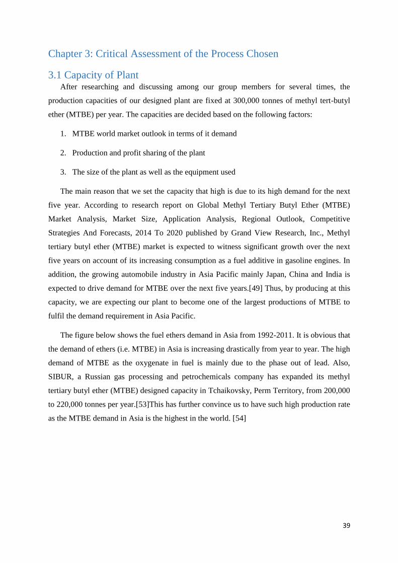
39
Chapter 3: Critical Assessment of the Process Chosen
3.1 Capacity of Plant After researching and discussing among our group members for several times, the
production capacities of our designed plant are fixed at 300,000 tonnes of methyl tert-butyl
ether (MTBE) per year. The capacities are decided based on the following factors:
1. MTBE world market outlook in terms of it demand
2. Production and profit sharing of the plant
3. The size of the plant as well as the equipment used
The main reason that we set the capacity that high is due to its high demand for the next
five year. According to research report on Global Methyl Tertiary Butyl Ether (MTBE)
Market Analysis, Market Size, Application Analysis, Regional Outlook, Competitive
Strategies And Forecasts, 2014 To 2020 published by Grand View Research, Inc., Methyl
tertiary butyl ether (MTBE) market is expected to witness significant growth over the next
five years on account of its increasing consumption as a fuel additive in gasoline engines. In
addition, the growing automobile industry in Asia Pacific mainly Japan, China and India is
expected to drive demand for MTBE over the next five years.[49] Thus, by producing at this
capacity, we are expecting our plant to become one of the largest productions of MTBE to
fulfil the demand requirement in Asia Pacific.
The figure below shows the fuel ethers demand in Asia from 1992-2011. It is obvious that
the demand of ethers (i.e. MTBE) in Asia is increasing drastically from year to year. The high
demand of MTBE as the oxygenate in fuel is mainly due to the phase out of lead. Also,
SIBUR, a Russian gas processing and petrochemicals company has expanded its methyl
tertiary butyl ether (MTBE) designed capacity in Tchaikovsky, Perm Territory, from 200,000
to 220,000 tonnes per year.[53]This has further convince us to have such high production rate
as the MTBE demand in Asia is the highest in the world. [54]
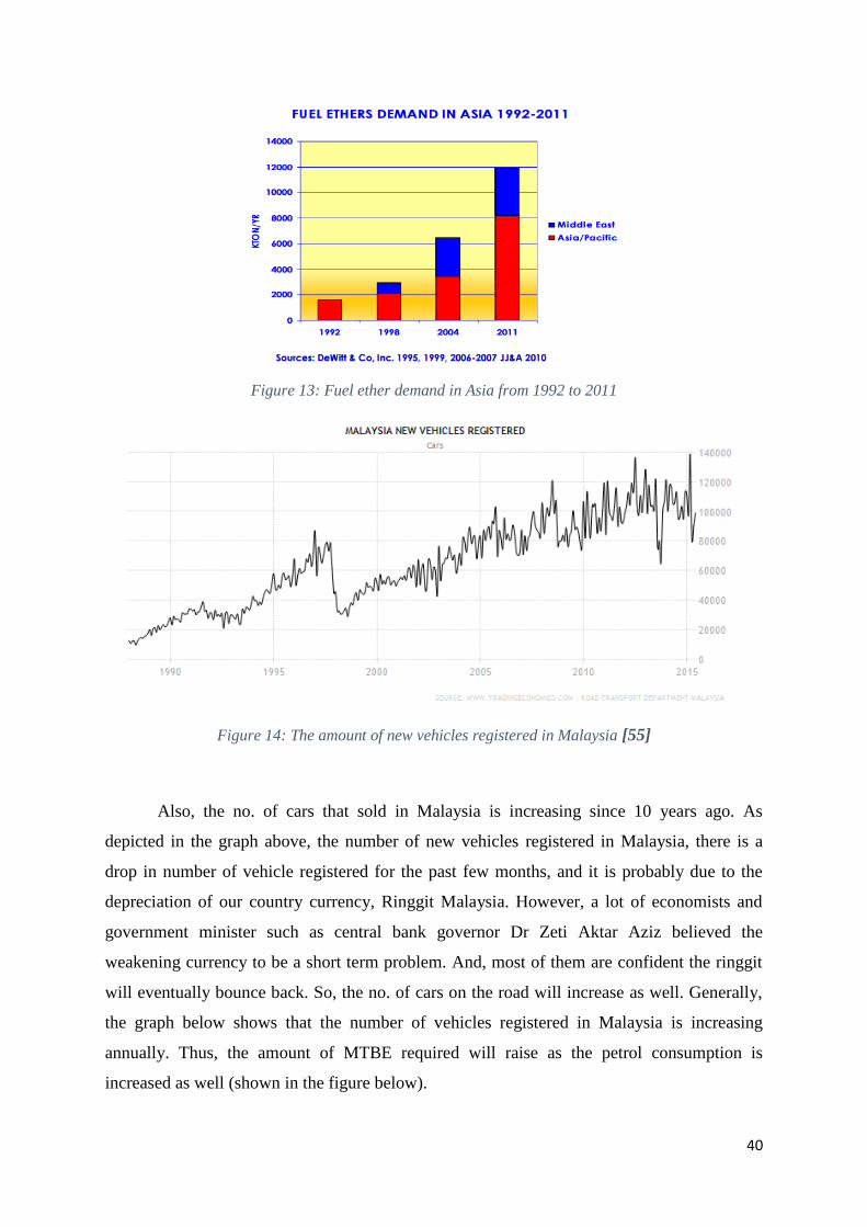
40
Figure 13: Fuel ether demand in Asia from 1992 to 2011
Figure 14: The amount of new vehicles registered in Malaysia [55]
Also, the no. of cars that sold in Malaysia is increasing since 10 years ago. As
depicted in the graph above, the number of new vehicles registered in Malaysia, there is a
drop in number of vehicle registered for the past few months, and it is probably due to the
depreciation of our country currency, Ringgit Malaysia. However, a lot of economists and
government minister such as central bank governor Dr Zeti Aktar Aziz believed the
weakening currency to be a short term problem. And, most of them are confident the ringgit
will eventually bounce back. So, the no. of cars on the road will increase as well. Generally,
the graph below shows that the number of vehicles registered in Malaysia is increasing
annually. Thus, the amount of MTBE required will raise as the petrol consumption is
increased as well (shown in the figure below).
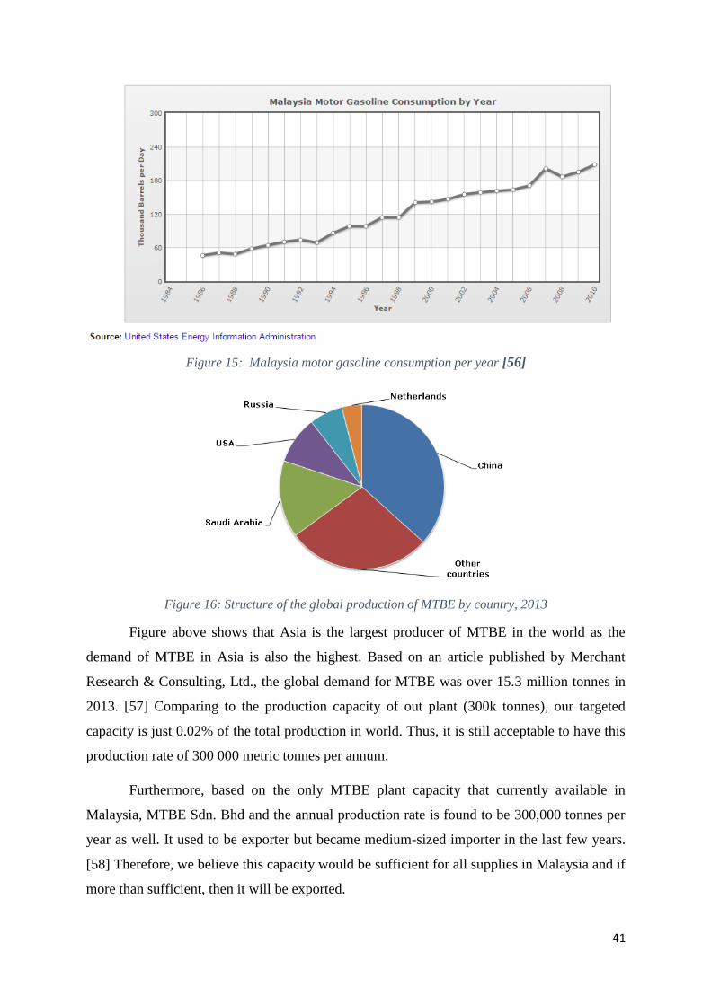
41
Figure 15: Malaysia motor gasoline consumption per year [56]
Figure 16: Structure of the global production of MTBE by country, 2013
Figure above shows that Asia is the largest producer of MTBE in the world as the
demand of MTBE in Asia is also the highest. Based on an article published by Merchant
Research & Consulting, Ltd., the global demand for MTBE was over 15.3 million tonnes in
2013. [57] Comparing to the production capacity of out plant (300k tonnes), our targeted
capacity is just 0.02% of the total production in world. Thus, it is still acceptable to have this
production rate of 300 000 metric tonnes per annum.
Furthermore, based on the only MTBE plant capacity that currently available in
Malaysia, MTBE Sdn. Bhd and the annual production rate is found to be 300,000 tonnes per
year as well. It used to be exporter but became medium-sized importer in the last few years.
[58] Therefore, we believe this capacity would be sufficient for all supplies in Malaysia and if
more than sufficient, then it will be exported.
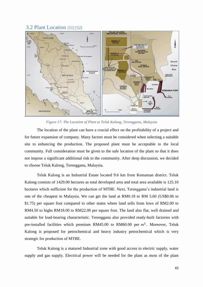
42
3.2 Plant Location [51] [52]
Figure 17: The Location of Plant at Teluk Kalong, Terengganu, Malaysia
The location of the plant can have a crucial effect on the profitability of a project and
for future expansion of company. Many factors must be considered when selecting a suitable
site to enhancing the production. The proposed plant must be acceptable to the local
community. Full consideration must be given to the safe location of the plant so that it does
not impose a significant additional risk to the community. After deep discussion, we decided
to choose Teluk Kalong, Terengganu, Malaysia.
Teluk Kalong is an Industrial Estate located 9.6 km from Kemaman district. Teluk
Kalong consists of 1429.00 hectares as total developed area and total area available is 125.10
hectares which sufficient for the production of MTBE. Next, Terengganu’s industrial land is
one of the cheapest in Malaysia. We can get the land at RM0.18 to RM 5.60 (US$0.06 to
$1.75) per square foot compared to other states where land sells from lows of RM2.00 to
RM4.50 to highs RM18.00 to RM22.00 per square foot. The land also flat, well drained and
suitable for load-bearing characteristic. Terengganu also provided ready-built factories with
pre-installed facilities which premium RM45.00 to RM60.00 per 𝑚2 . Moreover, Teluk
Kalong is proposed for petrochemical and heavy industry petrochemical which is very
strategic for production of MTBE.
Teluk Kalong is a matured Industrial zone with good access to electric supply, water
supply and gas supply. Electrical power will be needed for the plant as most of the plant
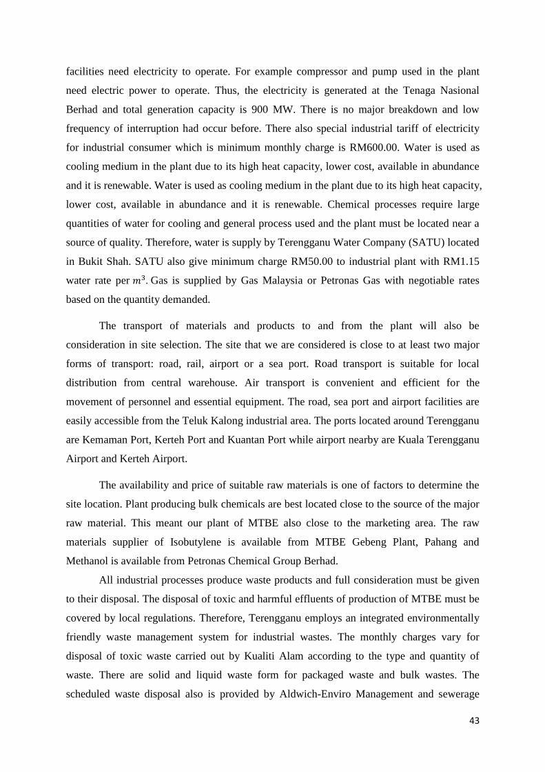
43
facilities need electricity to operate. For example compressor and pump used in the plant
need electric power to operate. Thus, the electricity is generated at the Tenaga Nasional
Berhad and total generation capacity is 900 MW. There is no major breakdown and low
frequency of interruption had occur before. There also special industrial tariff of electricity
for industrial consumer which is minimum monthly charge is RM600.00. Water is used as
cooling medium in the plant due to its high heat capacity, lower cost, available in abundance
and it is renewable. Water is used as cooling medium in the plant due to its high heat capacity,
lower cost, available in abundance and it is renewable. Chemical processes require large
quantities of water for cooling and general process used and the plant must be located near a
source of quality. Therefore, water is supply by Terengganu Water Company (SATU) located
in Bukit Shah. SATU also give minimum charge RM50.00 to industrial plant with RM1.15
water rate per 𝑚3. Gas is supplied by Gas Malaysia or Petronas Gas with negotiable rates
based on the quantity demanded.
The transport of materials and products to and from the plant will also be
consideration in site selection. The site that we are considered is close to at least two major
forms of transport: road, rail, airport or a sea port. Road transport is suitable for local
distribution from central warehouse. Air transport is convenient and efficient for the
movement of personnel and essential equipment. The road, sea port and airport facilities are
easily accessible from the Teluk Kalong industrial area. The ports located around Terengganu
are Kemaman Port, Kerteh Port and Kuantan Port while airport nearby are Kuala Terengganu
Airport and Kerteh Airport.
The availability and price of suitable raw materials is one of factors to determine the
site location. Plant producing bulk chemicals are best located close to the source of the major
raw material. This meant our plant of MTBE also close to the marketing area. The raw
materials supplier of Isobutylene is available from MTBE Gebeng Plant, Pahang and
Methanol is available from Petronas Chemical Group Berhad.
All industrial processes produce waste products and full consideration must be given
to their disposal. The disposal of toxic and harmful effluents of production of MTBE must be
covered by local regulations. Therefore, Terengganu employs an integrated environmentally
friendly waste management system for industrial wastes. The monthly charges vary for
disposal of toxic waste carried out by Kualiti Alam according to the type and quantity of
waste. There are solid and liquid waste form for packaged waste and bulk wastes. The
scheduled waste disposal also is provided by Aldwich-Enviro Management and sewerage
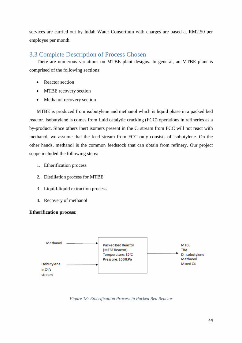
44
services are carried out by Indah Water Consortium with charges are based at RM2.50 per
employee per month.
3.3 Complete Description of Process Chosen There are numerous variations on MTBE plant designs. In general, an MTBE plant is
comprised of the following sections:
Reactor section
MTBE recovery section
Methanol recovery section
MTBE is produced from isobutylene and methanol which is liquid phase in a packed bed
reactor. Isobutylene is comes from fluid catalytic cracking (FCC) operations in refineries as a
by-product. Since others inert isomers present in the C4 stream from FCC will not react with
methanol, we assume that the feed stream from FCC only consists of isobutylene. On the
other hands, methanol is the common feedstock that can obtain from refinery. Our project
scope included the following steps:
1. Etherification process
2. Distillation process for MTBE
3. Liquid-liquid extraction process
4. Recovery of methanol
Etherification process:
Figure 18: Etherification Process in Packed Bed Reactor
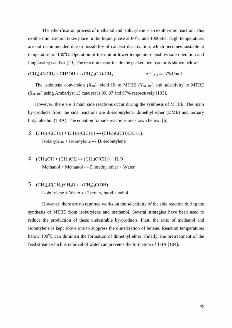
45
The etherification process of methanol and isobutylene is an exothermic reaction. This
exothermic reaction takes place in the liquid phase at 80oC and 1000kPa. High temperatures
are not recommended due to possibility of catalyst deactivation, which becomes unstable at
temperature of 130oC. Operation of the unit at lower temperature enables safe operation and
long lasting catalyst.[20] The reaction occur inside the packed bed reactor is shown below:
(CH3)2C=CH2 + CH3OH ↔ (CH3)3C-O-CH3 ∆Ho298 ≈ -37kJ/mol
The isobutene conversion (XIB), yield IB to MTBE (YMTBE) and selectivity to MTBE
(SMTBE) using Amberlyst 15 catalyst is 90, 87 and 97% respectively [103].
However, there are 3 main side reactions occur during the synthesis of MTBE. The main
by-products from the side reactions are di-isobutylene, dimethyl ether (DME) and tertiary
butyl alcohol (TBA). The equation for side reactions are shown below: [6]
3 (CH3)2C(CH2) + (CH3)2C(CH2) ↔ (CH3)3C(CH)C(CH3)2
Isobutylene + Isobutylene ↔ Di-isobutylene
4 (CH3)OH + (CH3)OH ↔ (CH3)O(CH3) + H2O
Methanol + Methanol ↔ Dimethyl ether + Water
5 (CH3)2C(CH2)+ H2O ↔ (CH3)3C(OH)
Isobutylene + Water ↔ Tertiary butyl alcohol
However, there are no reported works on the selectivity of the side reaction during the
synthesis of MTBE from isobutylene and methanol. Several strategies have been used to
reduce the production of these undesirable by-products. First, the ratio of methanol and
isobutylene is kept above one to suppress the dimerization of butane. Reaction temperatures
below 100oC can diminish the formation of dimethyl ether. Finally, the pretreatment of the
feed stream which is removal of water can prevents the formation of TBA [104].
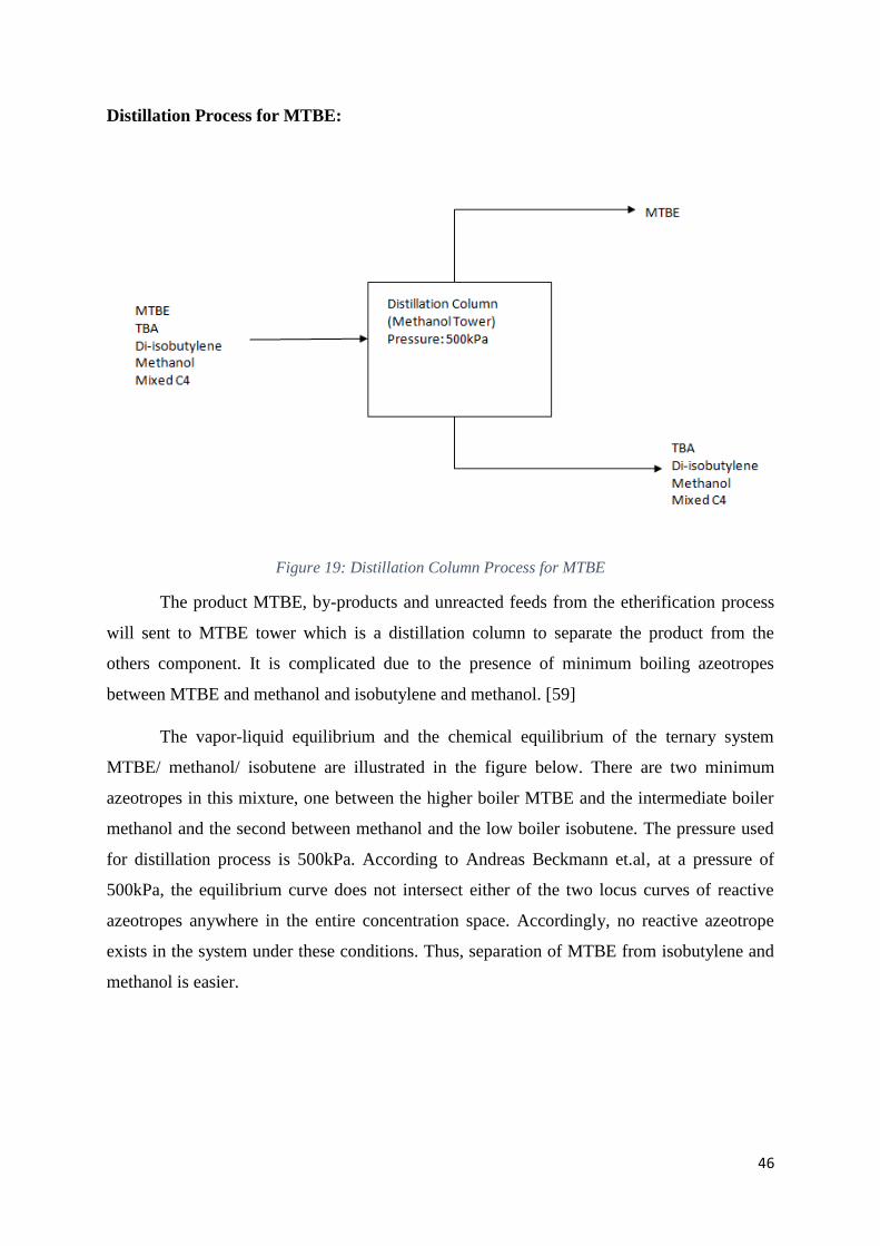
46
Distillation Process for MTBE:
Figure 19: Distillation Column Process for MTBE
The product MTBE, by-products and unreacted feeds from the etherification process
will sent to MTBE tower which is a distillation column to separate the product from the
others component. It is complicated due to the presence of minimum boiling azeotropes
between MTBE and methanol and isobutylene and methanol. [59]
The vapor-liquid equilibrium and the chemical equilibrium of the ternary system
MTBE/ methanol/ isobutene are illustrated in the figure below. There are two minimum
azeotropes in this mixture, one between the higher boiler MTBE and the intermediate boiler
methanol and the second between methanol and the low boiler isobutene. The pressure used
for distillation process is 500kPa. According to Andreas Beckmann et.al, at a pressure of
500kPa, the equilibrium curve does not intersect either of the two locus curves of reactive
azeotropes anywhere in the entire concentration space. Accordingly, no reactive azeotrope
exists in the system under these conditions. Thus, separation of MTBE from isobutylene and
methanol is easier.
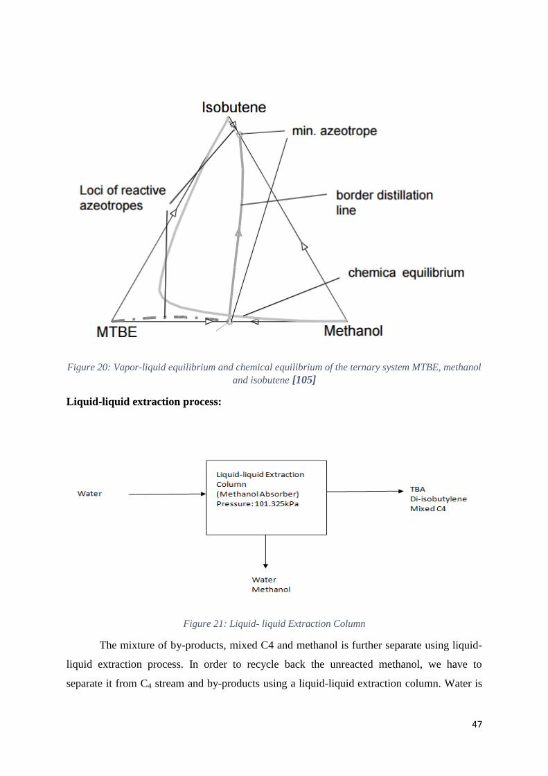
47
Figure 20: Vapor-liquid equilibrium and chemical equilibrium of the ternary system MTBE, methanol
and isobutene [105]
Liquid-liquid extraction process:
Figure 21: Liquid- liquid Extraction Column
The mixture of by-products, mixed C4 and methanol is further separate using liquid-
liquid extraction process. In order to recycle back the unreacted methanol, we have to
separate it from C4 stream and by-products using a liquid-liquid extraction column. Water is
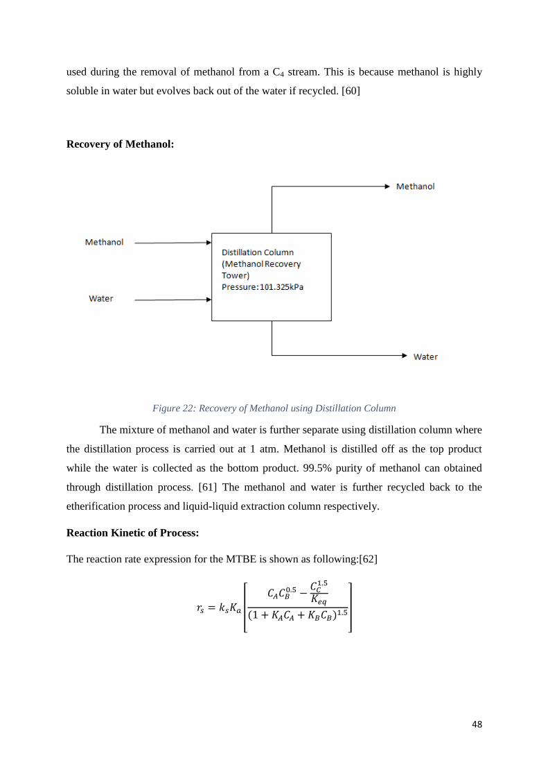
48
used during the removal of methanol from a C4 stream. This is because methanol is highly
soluble in water but evolves back out of the water if recycled. [60]
Recovery of Methanol:
Figure 22: Recovery of Methanol using Distillation Column
The mixture of methanol and water is further separate using distillation column where
the distillation process is carried out at 1 atm. Methanol is distilled off as the top product
while the water is collected as the bottom product. 99.5% purity of methanol can obtained
through distillation process. [61] The methanol and water is further recycled back to the
etherification process and liquid-liquid extraction column respectively.
Reaction Kinetic of Process:
The reaction rate expression for the MTBE is shown as following:[62]
𝑟𝑠 = 𝑘𝑠𝐾𝑎
[ 𝐶𝐴𝐶𝐵
0.5 −𝐶𝐶
1.5
𝐾𝑒𝑞
(1 + 𝐾𝐴𝐶𝐴 + 𝐾𝐵𝐶𝐵)1.5
]
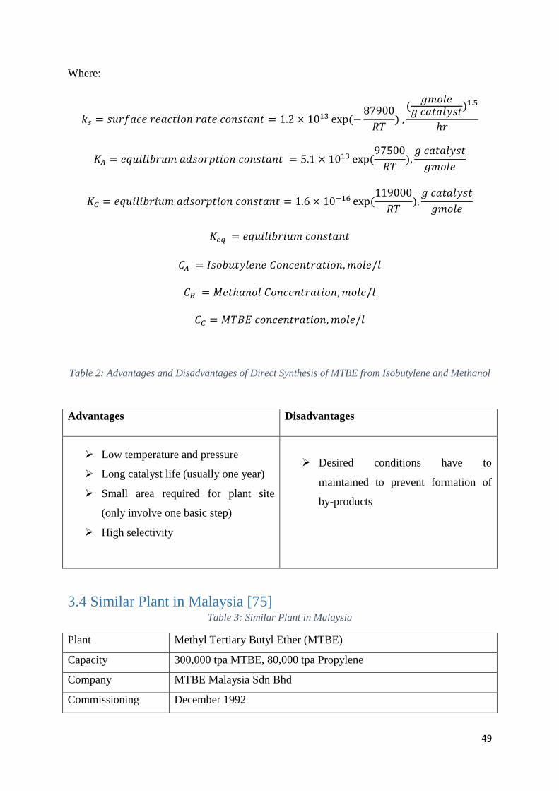
49
Where:
𝑘𝑠 = 𝑠𝑢𝑟𝑓𝑎𝑐𝑒 𝑟𝑒𝑎𝑐𝑡𝑖𝑜𝑛 𝑟𝑎𝑡𝑒 𝑐𝑜𝑛𝑠𝑡𝑎𝑛𝑡 = 1.2 × 10¹³ exp(−87900
𝑅𝑇) ,
(𝑔𝑚𝑜𝑙𝑒
𝑔 𝑐𝑎𝑡𝑎𝑙𝑦𝑠𝑡)1.5
ℎ𝑟
𝐾𝐴 = 𝑒𝑞𝑢𝑖𝑙𝑖𝑏𝑟𝑢𝑚 𝑎𝑑𝑠𝑜𝑟𝑝𝑡𝑖𝑜𝑛 𝑐𝑜𝑛𝑠𝑡𝑎𝑛𝑡 = 5.1 × 10¹³ exp(97500
𝑅𝑇),
𝑔 𝑐𝑎𝑡𝑎𝑙𝑦𝑠𝑡
𝑔𝑚𝑜𝑙𝑒
𝐾𝐶 = 𝑒𝑞𝑢𝑖𝑙𝑖𝑏𝑟𝑖𝑢𝑚 𝑎𝑑𝑠𝑜𝑟𝑝𝑡𝑖𝑜𝑛 𝑐𝑜𝑛𝑠𝑡𝑎𝑛𝑡 = 1.6 × 10⁻¹⁶ exp(119000
𝑅𝑇),
𝑔 𝑐𝑎𝑡𝑎𝑙𝑦𝑠𝑡
𝑔𝑚𝑜𝑙𝑒
𝐾𝑒𝑞 = 𝑒𝑞𝑢𝑖𝑙𝑖𝑏𝑟𝑖𝑢𝑚 𝑐𝑜𝑛𝑠𝑡𝑎𝑛𝑡
𝐶𝐴 = 𝐼𝑠𝑜𝑏𝑢𝑡𝑦𝑙𝑒𝑛𝑒 𝐶𝑜𝑛𝑐𝑒𝑛𝑡𝑟𝑎𝑡𝑖𝑜𝑛,𝑚𝑜𝑙𝑒/𝑙
𝐶𝐵 = 𝑀𝑒𝑡ℎ𝑎𝑛𝑜𝑙 𝐶𝑜𝑛𝑐𝑒𝑛𝑡𝑟𝑎𝑡𝑖𝑜𝑛,𝑚𝑜𝑙𝑒/𝑙
𝐶𝐶 = 𝑀𝑇𝐵𝐸 𝑐𝑜𝑛𝑐𝑒𝑛𝑡𝑟𝑎𝑡𝑖𝑜𝑛,𝑚𝑜𝑙𝑒/𝑙
Table 2: Advantages and Disadvantages of Direct Synthesis of MTBE from Isobutylene and Methanol
Advantages Disadvantages
Low temperature and pressure
Long catalyst life (usually one year)
Small area required for plant site
(only involve one basic step)
High selectivity
Desired conditions have to
maintained to prevent formation of
by-products
3.4 Similar Plant in Malaysia [75] Table 3: Similar Plant in Malaysia
Plant Methyl Tertiary Butyl Ether (MTBE)
Capacity 300,000 tpa MTBE, 80,000 tpa Propylene
Company MTBE Malaysia Sdn Bhd
Commissioning December 1992
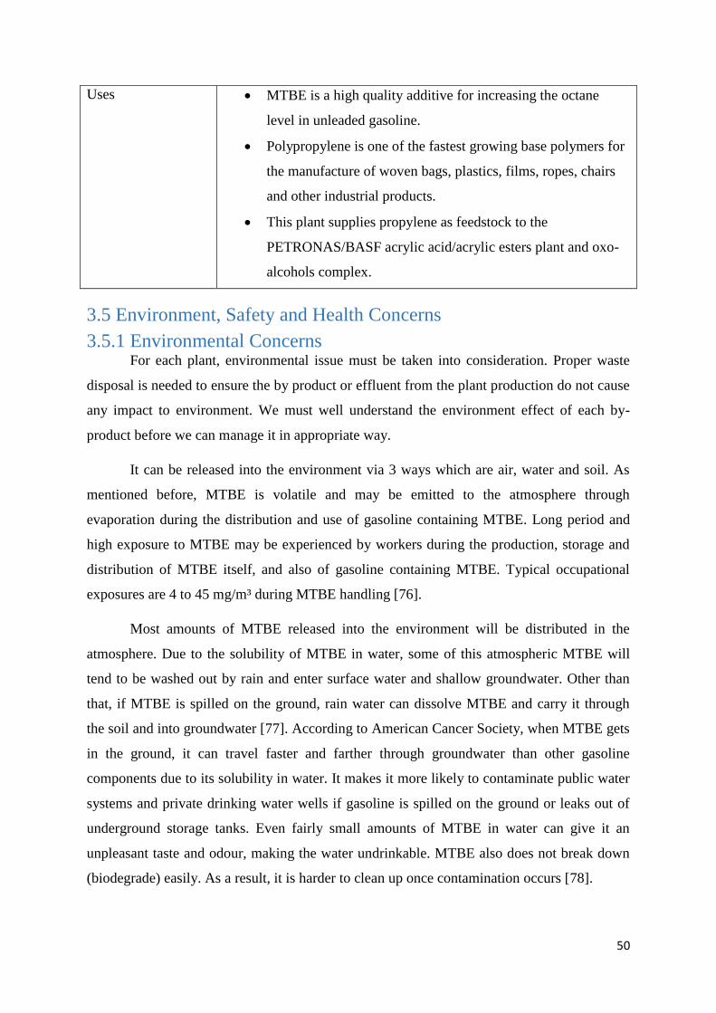
50
Uses MTBE is a high quality additive for increasing the octane
level in unleaded gasoline.
Polypropylene is one of the fastest growing base polymers for
the manufacture of woven bags, plastics, films, ropes, chairs
and other industrial products.
This plant supplies propylene as feedstock to the
PETRONAS/BASF acrylic acid/acrylic esters plant and oxo-
alcohols complex.
3.5 Environment, Safety and Health Concerns
3.5.1 Environmental Concerns For each plant, environmental issue must be taken into consideration. Proper waste
disposal is needed to ensure the by product or effluent from the plant production do not cause
any impact to environment. We must well understand the environment effect of each by-
product before we can manage it in appropriate way.
It can be released into the environment via 3 ways which are air, water and soil. As
mentioned before, MTBE is volatile and may be emitted to the atmosphere through
evaporation during the distribution and use of gasoline containing MTBE. Long period and
high exposure to MTBE may be experienced by workers during the production, storage and
distribution of MTBE itself, and also of gasoline containing MTBE. Typical occupational
exposures are 4 to 45 mg/m³ during MTBE handling [76].
Most amounts of MTBE released into the environment will be distributed in the
atmosphere. Due to the solubility of MTBE in water, some of this atmospheric MTBE will
tend to be washed out by rain and enter surface water and shallow groundwater. Other than
that, if MTBE is spilled on the ground, rain water can dissolve MTBE and carry it through
the soil and into groundwater [77]. According to American Cancer Society, when MTBE gets
in the ground, it can travel faster and farther through groundwater than other gasoline
components due to its solubility in water. It makes it more likely to contaminate public water
systems and private drinking water wells if gasoline is spilled on the ground or leaks out of
underground storage tanks. Even fairly small amounts of MTBE in water can give it an
unpleasant taste and odour, making the water undrinkable. MTBE also does not break down
(biodegrade) easily. As a result, it is harder to clean up once contamination occurs [78].
51
Although there are occasion that MTBE or gasoline contained MTBE spilled directly
into the soil, MTBE can be effectively remediated by two soil treatment technologies,
typically without any costs beyond those needed for remediating other petroleum constituents.
This is because MTBE has a very high vapour pressure and a low affinity for sorption to soil.
Soil vapour extraction (SVE) is an in-situ soil treatment technology that removes volatile
contaminants from soil in the unsaturated zone above groundwater by extracting the
contaminant vapours with a vacuum that is applied to the subsurface. Low-temperature
thermal desorption (LTTD) is an ex-situ soil treatment technology that uses temperatures
below ignition levels to separate volatile contaminants from soil. However, SVE and LTTD
must be used soon after a release, before most of the MBTE moves from the soil into the
groundwater [79].
Anyway, according to the latest scientific information, there is no indication that
MTBE can persist long enough in the air at a level which would cause harm to environment
as it will be destroyed in atmosphere within days by photo-oxidation reactions [76].
3.5.2 Safety Concerns Safety is the main criteria in any plant operation. Since the production of MTBE
involves a number of chemicals, standard operating procedures (SOP) should be employed to
assist with working safely. Disobeying the SOP may cause runaway reaction. Anyway,
proper control system is needed to regulate the system parameter such as the reactor
temperature, to ensure the process operating condition is maintained at appropriate value,
thus minimize the occurrence of accident. Lastly, personal protection equipment should be
worn all the time to avoid or at least minimize the injury whenever we are working in the
plant. Now, let’s focus on the main raw material and the main product formed in the plant.
As we all know, MTBE is very volatile. MTBE will quickly evaporate from open
containers. In the open air, it will quickly break down into other chemical compounds, with
half of it disappearing in about 4 hours [77]. However, MTBE is highly flammable, so all the
appropriate safety precautions should be strictly observed during handling. It is considered as
explosive if its concentration in air is between 1.3 and 8% by volume.[76] Hence, fire source
such as spark should be prohibited in the production plant as the fuel (MTBE vapor) and the
oxygen (from air) is abundant in the factory. Also, air ventilation ca be introduced to
dilute/disperse the evaporated MTBE around the production site.
52
There are no specific exposure limits for isobutylene. However, fires impinging
(direct flame) on the outside surface of unprotected pressure storage vessels of isobutylene
can be very dangerous. Direct flame exposure on the cylinder wall can cause an explosion
either by BLEVE (Boiling Liquid Expanding Vapor Explosion), or by exothermic
decomposition. When isobutylene is on fire, it can be extinguished by shutting off the source
of the gas. Then use water spray or a foam agent to cool fire-exposed containers, structures,
and equipment [80].
As required by OSHA, the highest limit of methanol in working environment is 200
ppm TWA or 260 mg/m3 TWA. Since methanol is alcohol, it is considered as flammable as
well. To extinguish the fire burn on the methanol, water spray is recommended. Although
other side reaction can be avoided by operating the reaction at specified temperature range,
similar cares should be taken as well since all the product and side products are hydrocarbon
which have increased the fire hazard. Rubber gloves, face shield, chemical splash goggles
and appropriate attires (chemical resistant pants, jackets and shoes) should be worn when
handling with all types of chemical.
3.5.3 Health Concern MTBE enters the body through breathing and swallowing water contaminated with
MTBE. EPA has determined that MTBE has a potential to cause hazardous effects in humans.
Some people have complained of symptoms such as nausea, dizziness, and light-headedness,
headaches, and nose and throat irritation after breathing vapours from gas containing MTBE.
But it’s not clear if these symptoms are caused by MTBE or other components of gasoline
[81].
Although there is no scientific evidence to indicate MTBE is a human carcinogen or a
serious health threat, a number of laboratory studies of animals exposed to high doses of
MTBE have showed stomach irritation, liver and kidney damage, and nervous system effects.
Some of the studies also indicate an increase in liver and kidney cancer in rats and mice that
breathed high levels of MTBE or consumed high concentrations of the chemical [82].
Several national and international agencies study substances in the environment to
determine if they can cause cancer. These agencies include National Toxicology Program
(NTP), International Agency for Research on Cancer (IARC) and Environmental Protection
Agency (EPA). The EPA maintains the Integrated Risk Information System (IRIS), an
electronic database that contains information on human health effects from exposure to
53
various substances in the environment. EPA’s Office of Water has concluded that there isn’t
enough evidence to estimate potential health risks of MTBE at low exposure levels in
drinking water, but that the evidence supports the conclusion that MTBE is a potential human
carcinogen at high doses. Thus, excessive intake of MTBE should be avoided for the sake of
human health [82].
Similarly, Chronic inhalation or oral exposure to methanol may result in headache,
dizziness, giddiness, insomnia, nausea, gastric disturbances, conjunctivitis, visual
disturbances (blurred vision), and blindness in humans. The large quantity of methanol
ingestion can be toxic but this is not considered possible under normal process operation.
3.6 Projected Demands/Supply for Next 10 years As stated earlier, MTBE is widely used in gasoline as an octane booster and
oxygenate. It can also be used to make high purity isobutylene for butyl rubber and
polyisobutylene production. The product with high purity can also be used in pharmaceutical
intermediates production [83]. However, the main application of MTBE is still as a gasoline
additive; this end use accounts for about 92% of global product demand [84].
According to a report (Methyl Tertiary Butyl Ether (MTBE): 2015 World Market
Outlook and Forecast up to 2019) published by Merchant Research & Consulting Ltd on June
2015, they believe that the next few years consumption of MTBE in developed countries will
decrease, but developing ones will show stable growth. Undeniably, the consumption of
MTBE in Western countries have been decreasing for the last few decades. MTBE used to be
popular until it was found out to be dangerous to the environment. USA, Canada, Japan and
Western Europe countries have shifted to ETBE, ethanol and other alternatives.
However, MTBE is still produced in North America but all amounts are exported. At
the same time Asia Pacific region increases MTBE capacity. As stated previously, China is
the largest country that is dominating the global MTBE demand [85]. According to another
Market Outlook report on MTBE published by Research and Market, China's demand for
Methyl Tert-Butyl Ether (MTBE) has grown at a fast pace in the past decade. In the next
decade, both production and demand will continue to grow [86]. Also, a market research
report on Methyl Tert-Butyl Ether (MTBE) Markets in China published on August this year
has also claimed that both the production and demand of MTBE in China will continue to
grow in the next decade [87].
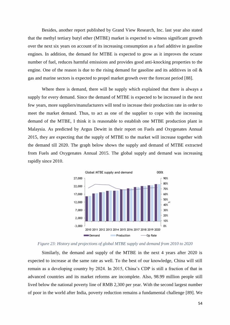
54
Besides, another report published by Grand View Research, Inc. last year also stated
that the methyl tertiary butyl ether (MTBE) market is expected to witness significant growth
over the next six years on account of its increasing consumption as a fuel additive in gasoline
engines. In addition, the demand for MTBE is expected to grow as it improves the octane
number of fuel, reduces harmful emissions and provides good anti-knocking properties to the
engine. One of the reason is due to the rising demand for gasoline and its additives in oil &
gas and marine sectors is expected to propel market growth over the forecast period [88].
Where there is demand, there will be supply which explained that there is always a
supply for every demand. Since the demand of MTBE is expected to be increased in the next
few years, more suppliers/manufacturers will tend to increase their production rate in order to
meet the market demand. Thus, to act as one of the supplier to cope with the increasing
demand of the MTBE, I think it is reasonable to establish one MTBE production plant in
Malaysia. As predicted by Argus Dewitt in their report on Fuels and Oxygenates Annual
2015, they are expecting that the supply of MTBE to the market will increase together with
the demand till 2020. The graph below shows the supply and demand of MTBE extracted
from Fuels and Oxygenates Annual 2015. The global supply and demand was increasing
rapidly since 2010.
Figure 23: History and projections of global MTBE supply and demand from 2010 to 2020
Similarly, the demand and supply of the MTBE in the next 4 years after 2020 is
expected to increase at the same rate as well. To the best of our knowledge, China will still
remain as a developing country by 2024. In 2015, China’s CDP is still a fraction of that in
advanced countries and its market reforms are incomplete. Also, 98.99 million people still
lived below the national poverty line of RMB 2,300 per year. With the second largest number
of poor in the world after India, poverty reduction remains a fundamental challenge [89]. We
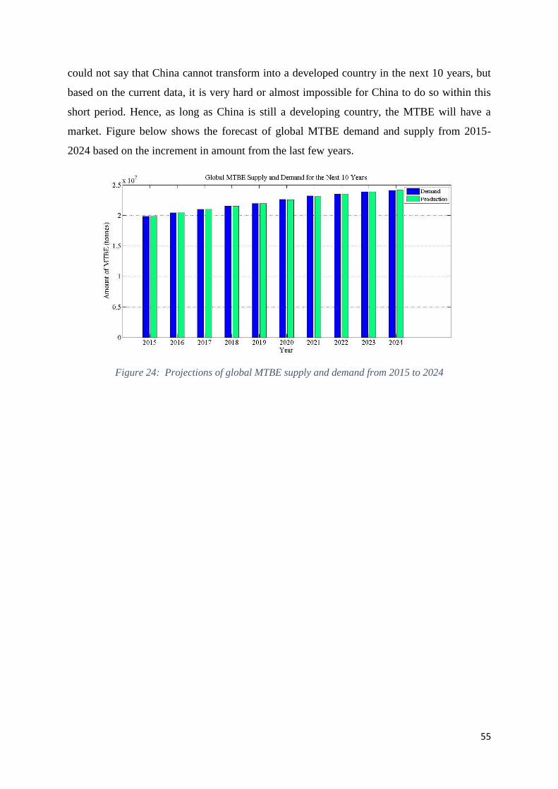
55
could not say that China cannot transform into a developed country in the next 10 years, but
based on the current data, it is very hard or almost impossible for China to do so within this
short period. Hence, as long as China is still a developing country, the MTBE will have a
market. Figure below shows the forecast of global MTBE demand and supply from 2015-
2024 based on the increment in amount from the last few years.
Figure 24: Projections of global MTBE supply and demand from 2015 to 2024
56
Chapter 4 Process Synthesis Structure and Analysis
4.1 Input-Output Structure Figure below shows all input and output streams that are involved in the process of
production of MTBE.
The input streams are:
1. Isobutylene uses as raw material from fluid catalytic cracking (FCC) operation in
refinery which is also known as isobutylene in C4’s stream since it consists of others
inert isomers besides isobutylene.
2. Pure methanol from refinery uses as raw material for the production of MTBE
3. Water uses for liquid-liquid extraction to remove methanol from mixed C4 stream and
by-products.
The output streams are:
1. MTBE which is the desired product in this process
2. Mixed C4’s stream which is waste product in this process.
3. A trace amount of by-products which are TBA and Di-isobutylene in the
etherification process.
The recycled streams are:
1. Recycle stream of methanol from distillation tower
2. Recycle stream of water from distillation tower
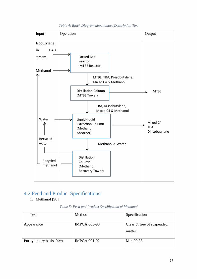
57
Table 4: Block Diagram about above Description Text
Input Operation Output
Isobutylene
in C4’s
stream
Methanol
4.2 Feed and Product Specifications: 1. Methanol [90]
Table 5: Feed and Product Specification of Methanol
Test Method Specification
Appearance IMPCA 003-98 Clear & free of suspended
matter
Purity on dry basis, %wt. IMPCA 001-02 Min 99.85
Packed Bed Reactor (MTBE Reactor)
MTBE, TBA, Di-isobutylene,
Mixed C4 & Methanol
Distillation Column (MTBE Tower)
MTBE
TBA, Di-isobutylene,
Mixed C4 & Methanol
Liquid-liquid Extraction Column (Methanol Absorber)
Water Mixed C4 TBA Di-isobutylene
Distillation Column (Methanol Recovery Tower)
Methanol & Water
Recycled
water
Recycled methanol
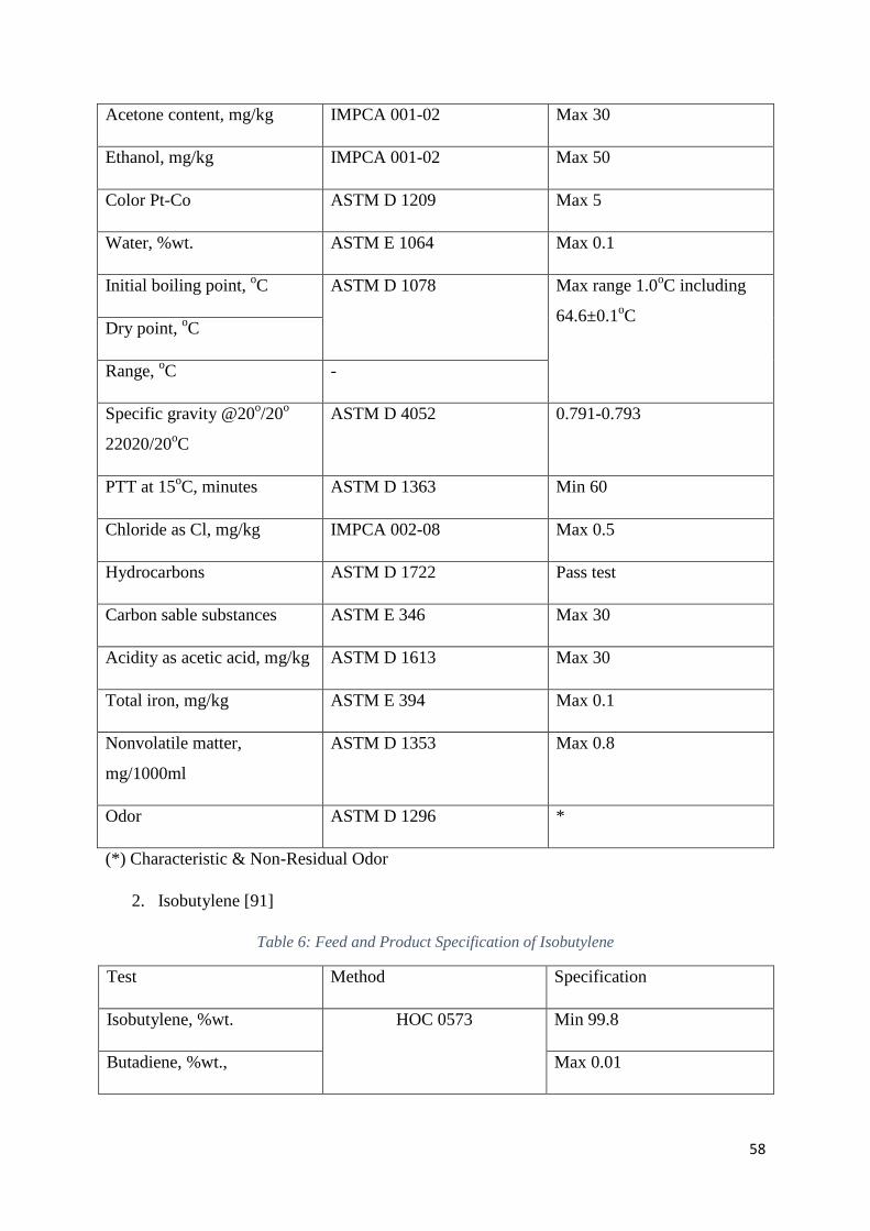
58
Acetone content, mg/kg IMPCA 001-02 Max 30
Ethanol, mg/kg IMPCA 001-02 Max 50
Color Pt-Co ASTM D 1209 Max 5
Water, %wt. ASTM E 1064 Max 0.1
Initial boiling point, oC ASTM D 1078 Max range 1.0
oC including
64.6±0.1oC
Dry point, oC
Range, oC -
Specific gravity @20o/20
o
22020/20oC
ASTM D 4052 0.791-0.793
PTT at 15oC, minutes ASTM D 1363 Min 60
Chloride as Cl, mg/kg IMPCA 002-08 Max 0.5
Hydrocarbons ASTM D 1722 Pass test
Carbon sable substances ASTM E 346 Max 30
Acidity as acetic acid, mg/kg ASTM D 1613 Max 30
Total iron, mg/kg ASTM E 394 Max 0.1
Nonvolatile matter,
mg/1000ml
ASTM D 1353 Max 0.8
Odor ASTM D 1296 *
(*) Characteristic & Non-Residual Odor
2. Isobutylene [91]
Table 6: Feed and Product Specification of Isobutylene
Test Method Specification
Isobutylene, %wt. HOC 0573
Min 99.8
Butadiene, %wt., Max 0.01
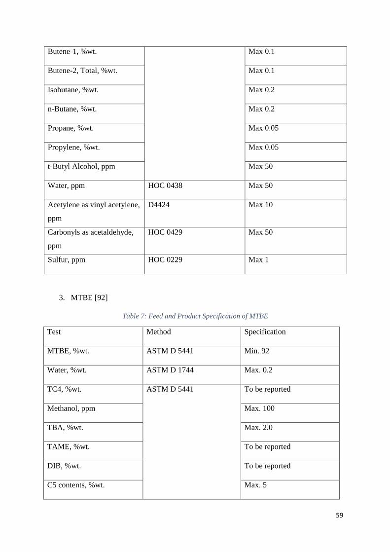
59
Butene-1, %wt. Max 0.1
Butene-2, Total, %wt. Max 0.1
Isobutane, %wt. Max 0.2
n-Butane, %wt. Max 0.2
Propane, %wt. Max 0.05
Propylene, %wt. Max 0.05
t-Butyl Alcohol, ppm Max 50
Water, ppm HOC 0438 Max 50
Acetylene as vinyl acetylene,
ppm
D4424 Max 10
Carbonyls as acetaldehyde,
ppm
HOC 0429 Max 50
Sulfur, ppm HOC 0229 Max 1
3. MTBE [92]
Table 7: Feed and Product Specification of MTBE
Test Method Specification
MTBE, %wt. ASTM D 5441 Min. 92
Water, %wt. ASTM D 1744 Max. 0.2
TC4, %wt. ASTM D 5441 To be reported
Methanol, ppm Max. 100
TBA, %wt. Max. 2.0
TAME, %wt. To be reported
DIB, %wt. To be reported
C5 contents, %wt. Max. 5
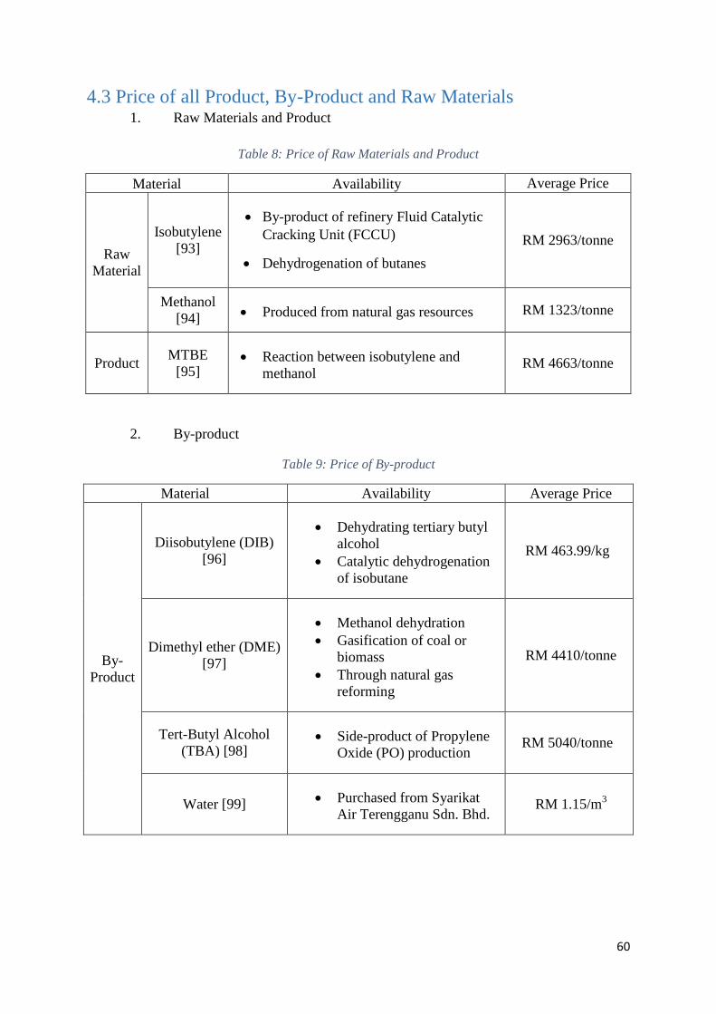
60
4.3 Price of all Product, By-Product and Raw Materials 1. Raw Materials and Product
Table 8: Price of Raw Materials and Product
Material Availability Average Price
Raw
Material
Isobutylene
[93]
By-product of refinery Fluid Catalytic
Cracking Unit (FCCU)
Dehydrogenation of butanes
RM 2963/tonne
Methanol
[94] Produced from natural gas resources RM 1323/tonne
Product MTBE
[95] Reaction between isobutylene and
methanol RM 4663/tonne
2. By-product
Table 9: Price of By-product
Material Availability Average Price
By-
Product
Diisobutylene (DIB)
[96]
Dehydrating tertiary butyl
alcohol
Catalytic dehydrogenation
of isobutane
RM 463.99/kg
Dimethyl ether (DME)
[97]
Methanol dehydration
Gasification of coal or
biomass
Through natural gas
reforming
RM 4410/tonne
Tert-Butyl Alcohol
(TBA) [98] Side-product of Propylene
Oxide (PO) production RM 5040/tonne
Water [99] Purchased from Syarikat
Air Terengganu Sdn. Bhd. RM 1.15/m
3
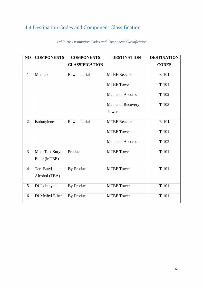
61
4.4 Destination Codes and Component Classification
Table 10: Destination Codes and Component Classification
NO COMPONENTS COMPONENTS
CLASSIFICATION
DESTINATION DESTINATION
CODES
1 Methanol Raw material MTBE Reactor R-101
MTBE Tower T-101
Methanol Absorber T-102
Methanol Recovery
Tower
T-103
2 Isobutylene Raw material MTBE Reactor R-101
MTBE Tower T-101
Methanol Absorber T-102
3 Mert-Tert-Butyl-
Ether (MTBE)
Product MTBE Tower T-101
4 Tert-Butyl
Alcohol (TBA)
By-Product MTBE Tower T-101
5 Di-Isobutylene By-Product MTBE Tower T-101
6 Di-Methyl Ether By-Product MTBE Tower T-101
62
4.5 Utilities of the Process
In MTBE production plants, utilities such as electricity, water and steam are important
for them.
Electricity
Electricity is needed for the plant operation as most of the plant facilities need
electricity to function. This is because electric motor is the most common used motor as it is
more efficient and very reliable in a wide range of wattage. Electrical component such as
pumps, control system, mixer and compressors. There are many electrical generation plants
which is able to supply required amount of electricity for example Tenaga Nasional Berhad
(TNB).
Water
Water is used to cool down the reactor by heat exchanger. Water is used as cooling
medium in the production of MTBE plant due to its high heat capacity, low cost, low
viscosity, non-hazardous, available in abundance and it is renewable. Water also can be used
in the jacketed system since this plant involved exothermic reaction. This reaction required
jacketed system in the reactor to control the temperature release from the reactor. The water
from heat exchanger and jacketed system can be recycling back without need to be treated
caused it cause no harm. Sources of water that supply to the plant are from Kemaman Port
and Kertih Port. Kemaman Port is Malaysian Deepwater general purpose Industrial Port. This
port is deepest in the region and can handle vessels up to 150,000dwt. Kertih Port is a marine
port and is managed by Petronas subsidiary company. It is a dedicated port for liquid
petrochemical products.
Steam
Steam is used as heating medium in heat. Steam is used to heat up or supply energy to
the plant that required to increase the temperature of the steams like reboiler and heat
exchanger.
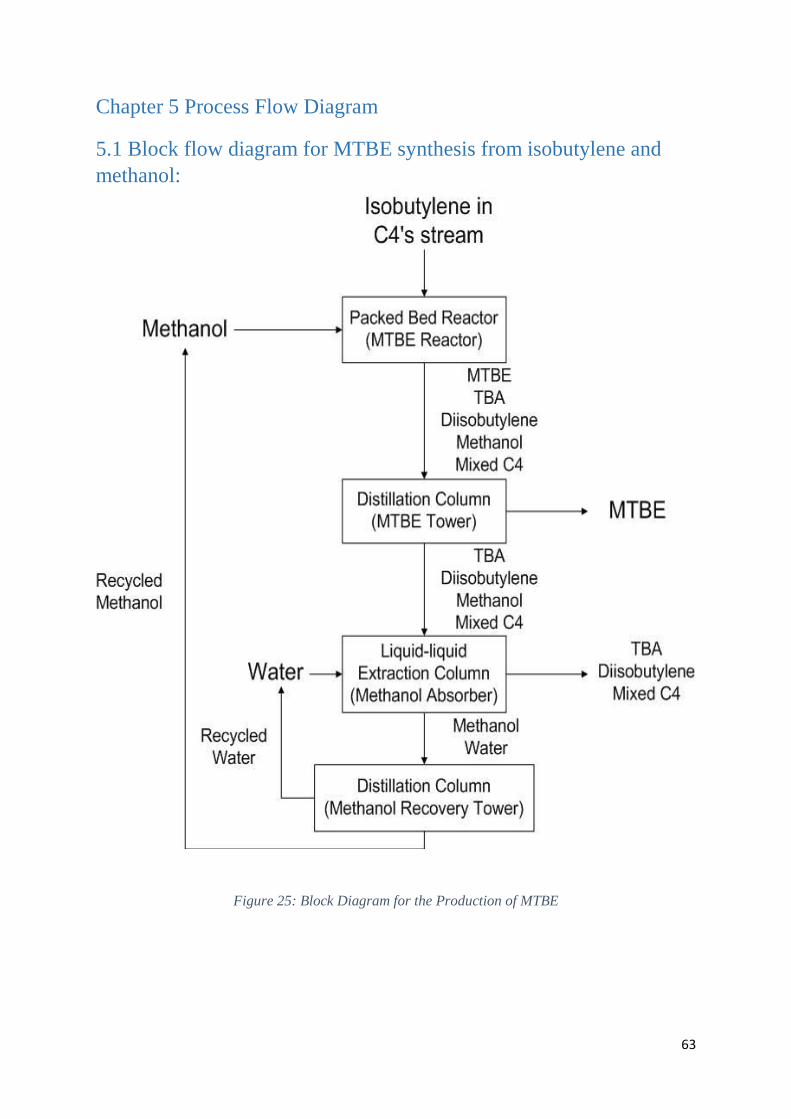
63
Chapter 5 Process Flow Diagram
5.1 Block flow diagram for MTBE synthesis from isobutylene and
methanol:
Figure 25: Block Diagram for the Production of MTBE
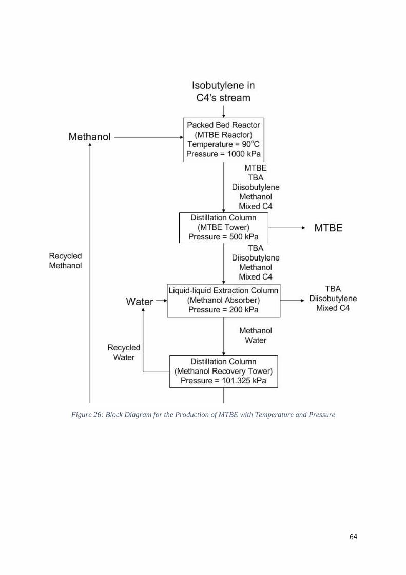
64
Figure 26: Block Diagram for the Production of MTBE with Temperature and Pressure
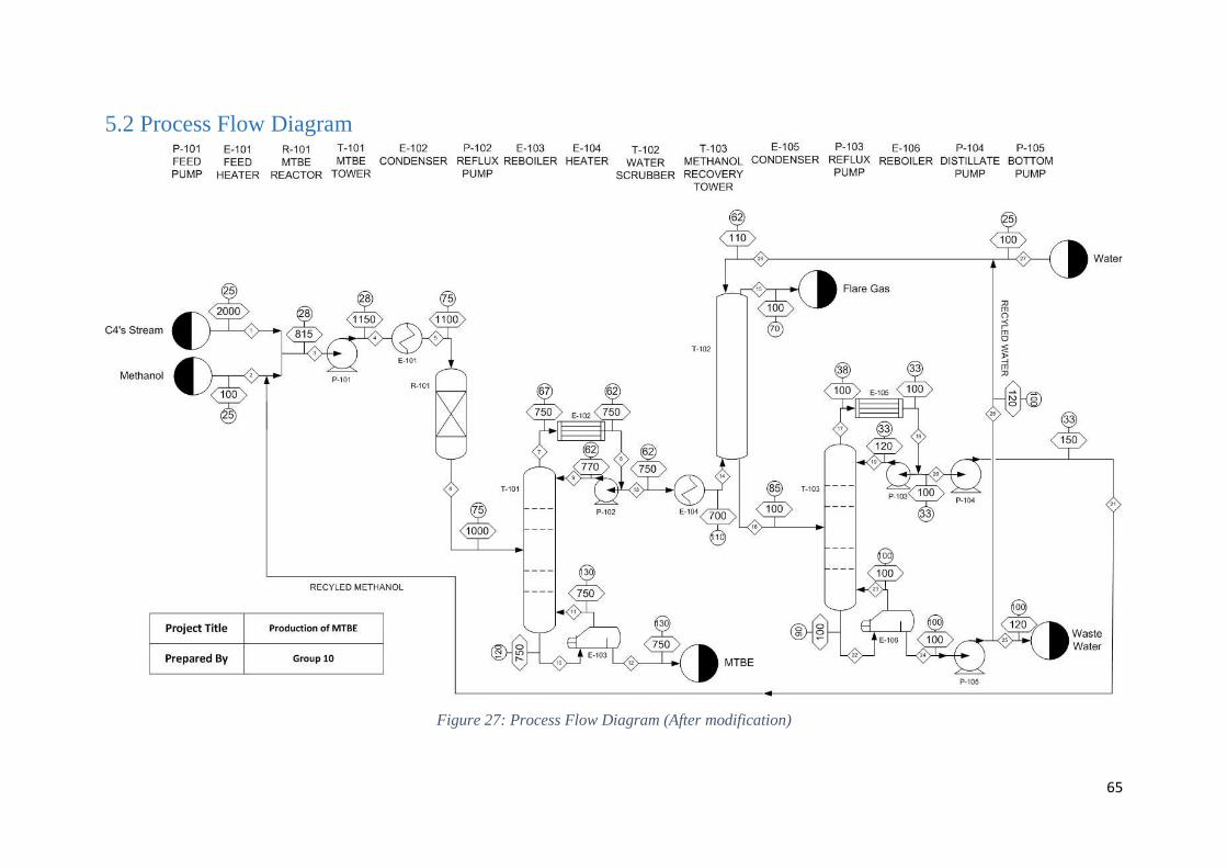
65
5.2 Process Flow Diagram
Figure 27: Process Flow Diagram (After modification)
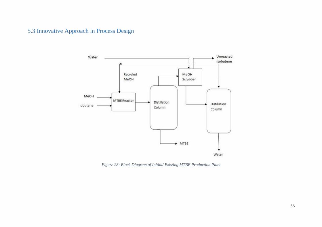
66
5.3 Innovative Approach in Process Design
Figure 28: Block Diagram of Initial/ Existing MTBE Production Plant
67
Figure 28 shows the initial/existing plant design of the direct synthesis of MTBE from
isobutylene and methanol and the plant design after modification is made. The followings are
the modification that has been introduced into the plant.
1. In order to ensure the complete reaction between isobutylene and methanol, the
amount of methanol added into the reactor is always 10% more than the
stoichiometric factor.
2. A centrifugal mixing pump is installed before both of the reactants are feed into the
reactor to promote mixing so that the reactants mix well with each other when
contacting with catalyst.
3. The water released from the second distillation column (Methanol Recovery Tower)
is recycled to liquid-liquid extraction column (Methanol Absorber) instead of draining
it away. By recycling the water, the usage of water can be reduced greatly. Anyway,
only 50% of the water released from the methanol recovery tower is recycled back
into methanol absorber, and the other 50% is still from water source. This is to make
sure that the water which acts as solvent will remain effective while reducing the cost
of water tariff.
Chapter 6 Process Analysis Figure 27 above shows the updated Process Flow Diagram (PFD) of the MTBE
production plant designed by Group 10. The whole process is started off by pumping the raw
materials, which are methanol and C4s (mainly isobutylene) into the reactor, R-101. This
reactor, R-101 is a packed bed reactor, which is filled with solid catalyst named Amberlyst-
15 resin catalyst. Inside this reactor, etherification has occurred to produce MTBE and other
undesired products that include tertiary butyl alcohol (TBA) and di-isobutylene (DIB).
Besides, impurities present in C4 stream such as butane, butene, 1,3-butadiene and unreacted
isobutylene and methanol also present in the effluent of the reactor. The operating condition
for this packed bed reactor (MTBE reactor) is maintained at 75 oC and 1000 kPa. The first
feed to the reactor, C4s (mainly constituted of isobutylene), is obtained from fluid catalytic
cracking (FCC) operations in refineries as a by-product, while the methanol, which derived
from natural gas is the ordered from petrochemical refinery. Both of the feeds are channeled
into a pipe and passed through a pre-heater, E-101 to increase the temperature of the feed to
75 oC as the reaction is favorable to occur at 75
oC. Then, a centrifugal mixing pump pumps
the heated methanol and isobutylene into the MTBE reactor. This pump will also promote
further mixing of both raw materials and enhance the reaction later in the reactor.
68
As mentioned above, etherification reaction will occur in the reactor, R-101 packed
with Amberlyst-15 Polymeric catalyst. The formation of MTBE from methanol and
isobutylene is an exothermic reaction. So, heat will generate as this reaction occur. On the
other hands, at 75 oC, the selectivity of the formation of MTBE is as high as 96.5%. Heat
produced during etherification reaction will cause temperature increase. From the literature, if
the reactor temperature more than 100 oC, it will promote the formation of by-product which
is dimethyl ether (DME). In order to maintain the temperature in the reactor at 75 oC
throughout the whole process, the reactor is jacketed so that a coolant can withdraw the heat
energy generated by this exothermic reaction. The flow rate of coolant in the cooling jacket is
controlled so that the desired temperature in reactor can be maintained.
Next, the outlet of the reactor is then fed into a distillation column, T-101 (MTBE
tower) where MTBE is collected as bottom product together with trace amount of by-
products. The operating pressure of this distillation column is maintained 750 kPa. A reboiler
is installed at the bottom of the distillation column to increase the purity of the MTBE
collected. Meanwhile, other undesired products are collected as distillate. A condenser is
installed at exit of distillate to enable reflux to occur.
The upper product from MTBE tower is then sent to a water scrubbber, T-102
(Methanol Absorber) to extract the unreacted methanol. Water is added into column to extract
methanol out from the C4 mixture. Methanol will dissolve in water to form water-methanol
mixture as the solubility of methanol in water is very high. This water-methanol mixture is
collected from the bottom of the absorber and send as feed into a second distillation column,
T-103. The top product of the absorber, mainly consist of other C4’s, is then combusted in a
furnace as they are all hydrocarbon. The pressure in the absorber is maintained at 100 kPa.
The second distillation column, T-103 (methanol recovery tower) is a unit operation that
used to separate the methanol and water so that they can be recycled to the feed of reactor R-
101 and the water is partially recycled back into the water scrubber, T-102 respectively. 50%
of the water collected from the methanol recovery tower is drained, and the other half is
mixed with fresh feed water to extract methanol again in water scrubber. The distillation
process is carried out at 100 kPa.
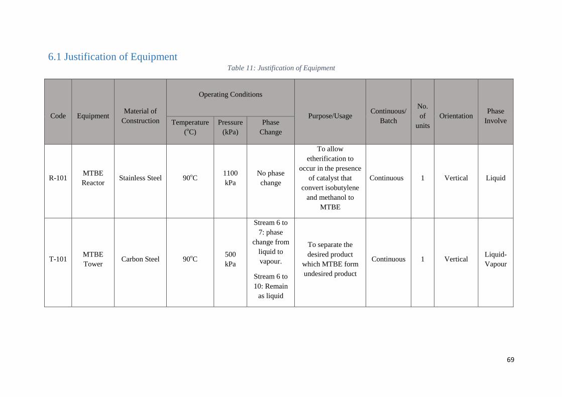
69
6.1 Justification of Equipment Table 11: Justification of Equipment
Code
Equipment
Material of
Construction
Operating Conditions
Purpose/Usage
Continuous/
Batch
No.
of
units
Orientation
Phase
Involve Temperature
(oC)
Pressure
(kPa)
Phase
Change
R-101 MTBE
Reactor Stainless Steel 90
oC
1100
kPa
No phase
change
To allow
etherification to
occur in the presence
of catalyst that
convert isobutylene
and methanol to
MTBE
Continuous 1 Vertical Liquid
T-101 MTBE
Tower Carbon Steel 90
oC
500
kPa
Stream 6 to
7: phase
change from
liquid to
vapour.
Stream 6 to
10: Remain
as liquid
To separate the
desired product
which MTBE form
undesired product
Continuous 1 Vertical Liquid-
Vapour
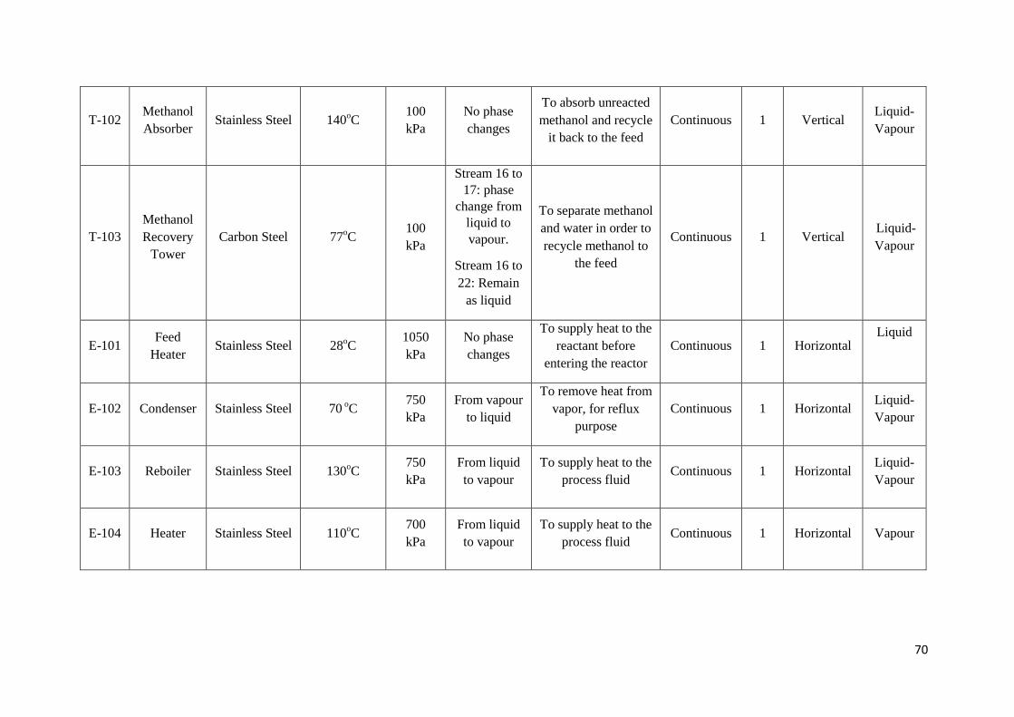
70
T-102 Methanol
Absorber Stainless Steel 140
oC
100
kPa
No phase
changes
To absorb unreacted
methanol and recycle
it back to the feed
Continuous 1 Vertical Liquid-
Vapour
T-103
Methanol
Recovery
Tower
Carbon Steel 77oC
100
kPa
Stream 16 to
17: phase
change from
liquid to
vapour.
Stream 16 to
22: Remain
as liquid
To separate methanol
and water in order to
recycle methanol to
the feed
Continuous 1 Vertical Liquid-
Vapour
E-101 Feed
Heater Stainless Steel 28
oC
1050
kPa
No phase
changes
To supply heat to the
reactant before
entering the reactor
Continuous 1 Horizontal Liquid
E-102 Condenser Stainless Steel 70 oC
750
kPa
From vapour
to liquid
To remove heat from
vapor, for reflux
purpose
Continuous 1 Horizontal Liquid-
Vapour
E-103 Reboiler Stainless Steel 130oC
750
kPa
From liquid
to vapour
To supply heat to the
process fluid Continuous 1 Horizontal
Liquid-
Vapour
E-104 Heater Stainless Steel 110oC
700
kPa
From liquid
to vapour
To supply heat to the
process fluid Continuous 1 Horizontal Vapour
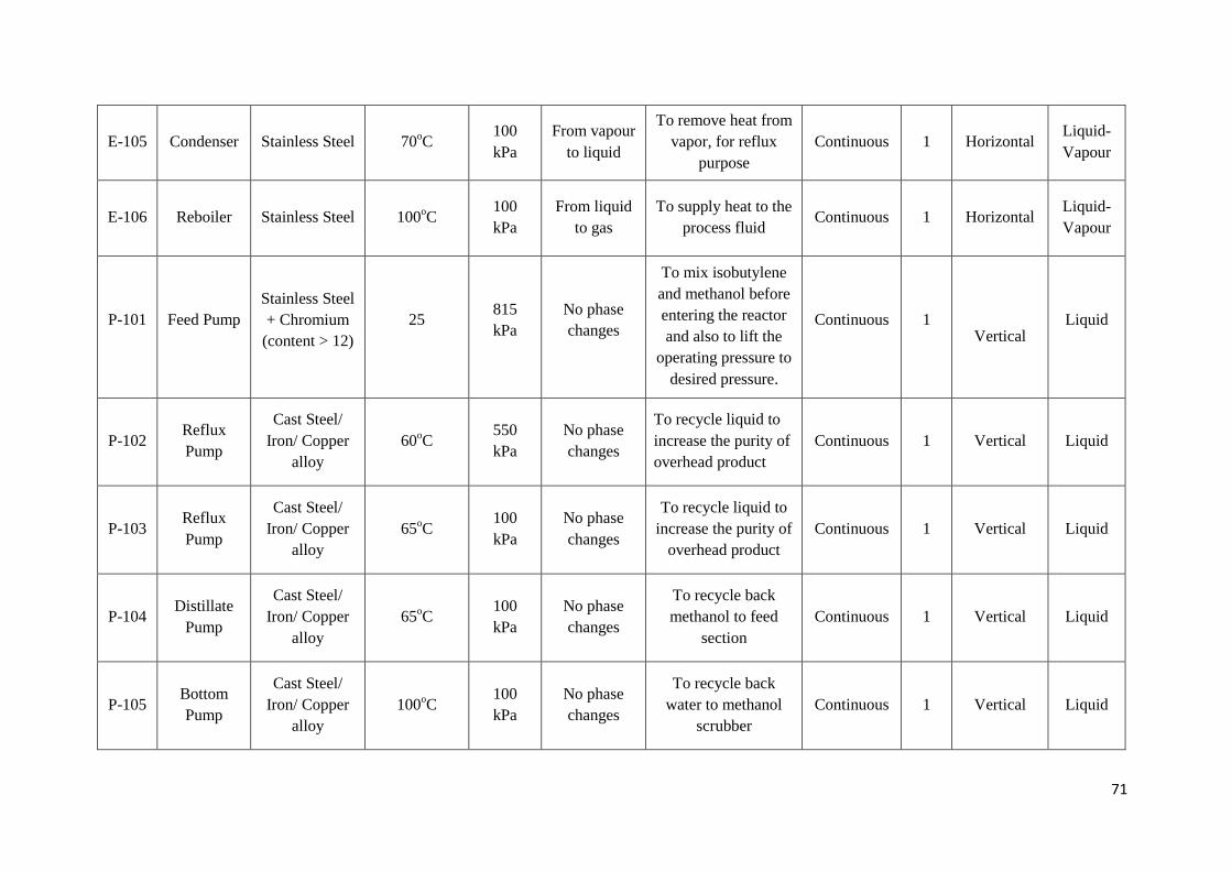
71
E-105 Condenser Stainless Steel 70oC
100
kPa
From vapour
to liquid
To remove heat from
vapor, for reflux
purpose
Continuous 1 Horizontal Liquid-
Vapour
E-106 Reboiler Stainless Steel 100oC
100
kPa
From liquid
to gas
To supply heat to the
process fluid Continuous 1 Horizontal
Liquid-
Vapour
P-101 Feed Pump
Stainless Steel
+ Chromium
(content > 12)
25 815
kPa
No phase
changes
To mix isobutylene
and methanol before
entering the reactor
and also to lift the
operating pressure to
desired pressure.
Continuous
1
Vertical
Liquid
P-102 Reflux
Pump
Cast Steel/
Iron/ Copper
alloy
60oC
550
kPa
No phase
changes
To recycle liquid to
increase the purity of
overhead product
Continuous
1
Vertical
Liquid
P-103 Reflux
Pump
Cast Steel/
Iron/ Copper
alloy
65oC
100
kPa
No phase
changes
To recycle liquid to
increase the purity of
overhead product
Continuous 1 Vertical Liquid
P-104 Distillate
Pump
Cast Steel/
Iron/ Copper
alloy
65oC
100
kPa
No phase
changes
To recycle back
methanol to feed
section
Continuous 1 Vertical Liquid
P-105 Bottom
Pump
Cast Steel/
Iron/ Copper
alloy
100oC
100
kPa
No phase
changes
To recycle back
water to methanol
scrubber
Continuous 1 Vertical Liquid
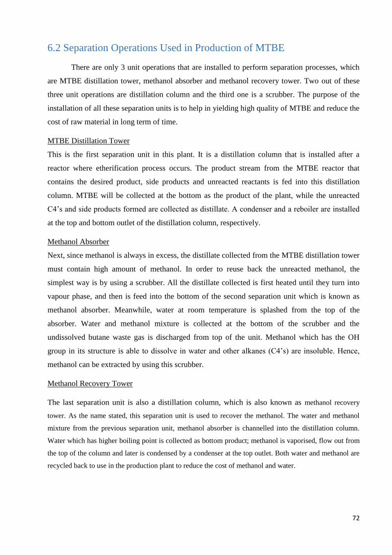
72
6.2 Separation Operations Used in Production of MTBE
There are only 3 unit operations that are installed to perform separation processes, which
are MTBE distillation tower, methanol absorber and methanol recovery tower. Two out of these
three unit operations are distillation column and the third one is a scrubber. The purpose of the
installation of all these separation units is to help in yielding high quality of MTBE and reduce the
cost of raw material in long term of time.
MTBE Distillation Tower
This is the first separation unit in this plant. It is a distillation column that is installed after a
reactor where etherification process occurs. The product stream from the MTBE reactor that
contains the desired product, side products and unreacted reactants is fed into this distillation
column. MTBE will be collected at the bottom as the product of the plant, while the unreacted
C4’s and side products formed are collected as distillate. A condenser and a reboiler are installed
at the top and bottom outlet of the distillation column, respectively.
Methanol Absorber
Next, since methanol is always in excess, the distillate collected from the MTBE distillation tower
must contain high amount of methanol. In order to reuse back the unreacted methanol, the
simplest way is by using a scrubber. All the distillate collected is first heated until they turn into
vapour phase, and then is feed into the bottom of the second separation unit which is known as
methanol absorber. Meanwhile, water at room temperature is splashed from the top of the
absorber. Water and methanol mixture is collected at the bottom of the scrubber and the
undissolved butane waste gas is discharged from top of the unit. Methanol which has the OH
group in its structure is able to dissolve in water and other alkanes (C4’s) are insoluble. Hence,
methanol can be extracted by using this scrubber.
Methanol Recovery Tower
The last separation unit is also a distillation column, which is also known as methanol recovery
tower. As the name stated, this separation unit is used to recover the methanol. The water and methanol
mixture from the previous separation unit, methanol absorber is channelled into the distillation column.
Water which has higher boiling point is collected as bottom product; methanol is vaporised, flow out from
the top of the column and later is condensed by a condenser at the top outlet. Both water and methanol are
recycled back to use in the production plant to reduce the cost of methanol and water.
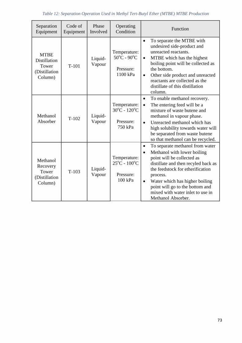
73
Table 12: Separation Operation Used in Methyl Tert-Butyl Ether (MTBE) MTBE Production
Separation
Equipment
Code of
Equipment
Phase
Involved
Operating
Condition Function
MTBE
Distillation
Tower
(Distillation
Column)
T-101
Liquid-
Vapour
Temperature:
50oC - 90
oC
Pressure:
1100 kPa
To separate the MTBE with
undesired side-product and
unreacted reactants.
MTBE which has the highest
boiling point will be collected as
the bottom.
Other side product and unreacted
reactants are collected as the
distillate of this distillation
column.
Methanol
Absorber T-102
Liquid-
Vapour
Temperature:
30oC - 120
oC
Pressure:
750 kPa
To enable methanol recovery.
The entering feed will be a
mixture of waste butene and
methanol in vapour phase.
Unreacted methanol which has
high solubility towards water will
be separated from waste butene
so that methanol can be recycled.
Methanol
Recovery
Tower
(Distillation
Column)
T-103 Liquid-
Vapour
Temperature:
25oC - 100
oC
Pressure:
100 kPa
To separate methanol from water
Methanol with lower boiling
point will be collected as
distillate and then recyled back as
the feedstock for etherification
process.
Water which has higher boiling
point will go to the bottom and
mixed with water inlet to use in
Methanol Absorber.
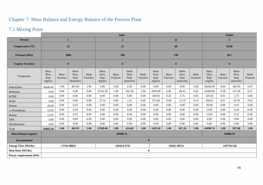
74
Chapter 7: Mass Balance and Energy Balance of the Process Plant
7.1 Mixing Point
Inlet Outlet
Stream 1 2 21 3
Temperature (℃) 25 25 60 28.00
Pressure (kPa) 2000 100 150 815
Vapour Fraction 0 0 0 0
Component
Mass
Flow
Rate
(kg/hr)
Mass
Fraction
Mole
Flow
Rate
(kmol/hr)
Mole
Fraction
Mass
Flow
Rate
(kg/hr)
Mass
Fraction
Mole
Flow
Rate
(kmol/hr)
Mole
Fraction
Mass
Flow
Rate
(kg/hr)
Mass
Fraction
Mole
Flow
Rate
(kmol/hr)
Mole
Fraction
Mass
Flow
Rate
(kg/hr)
Mass
Fraction
Mole
Flow
Rate
(kmol/hr)
Mole
Fraction
Isobutylene 26040.00 1.00 465.00 1.00 0.00 0.00 0.00 0.00 0.00 0.00 0.00 0.00 26040.00 0.60 465.00 0.47
Methanol 0.00 0.00 0.00 0.00 13541.92 1.00 423.18 1.00 2826.08 0.82 88.32 0.82 16368.00 0.38 511.50 0.51
MTBE 0.00 0.00 0.00 0.00 0.00 0.00 0.00 0.00 329.93 0.10 3.75 0.03 329.93 0.01 3.75 0.00
Water 0.00 0.00 0.00 0.00 27.14 0.00 1.51 0.00 273.49 0.08 15.19 0.14 300.62 0.01 16.70 0.02
Butene 26.09 0.00 0.47 0.00 0.00 0.00 0.00 0.00 0.00 0.00 0.00 0.00 26.09 0.00 0.47 0.00
1,3-butadienes 13.05 0.00 0.24 0.00 0.00 0.00 0.00 0.00 0.00 0.00 0.00 0.00 13.05 0.00 0.24 0.00
Butane 13.05 0.00 0.22 0.00 0.00 0.00 0.00 0.00 0.00 0.00 0.00 0.00 13.05 0.00 0.22 0.00
TBA 0.00 0.00 0.00 0.00 0.00 0.00 0.00 0.00 0.00 0.00 0.00 0.00 0.00 0.00 0.00 0.00
Diisobutylene 0.00 0.00 0.00 0.00 0.00 0.00 0.00 0.00 0.00 0.00 0.00 0.00 0.00 0.00 0.00 0.00
Total 26092.18 1.00 465.93 1.00 13569.06 1.00 424.69 1.00 3429.50 1.00 107.26 1.00 43090.74 1.00 997.88 1.00
Mass Balance (kg/hr) 43090.74 43090.74
Accumulation 0
Energy Flow (MJ/hr) -17541.88821 -101614.4722 -26561.40551 -145719.526
Heat Duty (MJ/hr) 0
Power requirement (kW) -
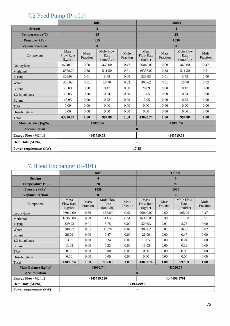
75
7.2 Feed Pump (P-101)
Inlet Outlet
Stream 3 4
Temperature (℃) 28 28
Pressure (kPa) 815 1050
Vapour Frection 0 0
Component
Mass
Flow Rate
(kg/hr)
Mass
Fraction
Mole Flow
Rate
(kmol/hr)
Mole
Fraction
Mass
Flow Rate
(kg/hr)
Mass
Fraction
Mole Flow
Rate
(kmol/hr)
Mole
Fraction
Isobutylene 26040.00 0.60 465.00 0.47 26040.00 0.60 465.00 0.47
Methanol 16368.00 0.38 511.50 0.51 16368.00 0.38 511.50 0.51
MTBE 329.93 0.01 3.75 0.00 329.93 0.01 3.75 0.00
Water 300.62 0.01 16.70 0.02 300.62 0.01 16.70 0.02
Butene 26.09 0.00 0.47 0.00 26.09 0.00 0.47 0.00
1,3-butadienes 13.05 0.00 0.24 0.00 13.05 0.00 0.24 0.00
Butane 13.05 0.00 0.22 0.00 13.05 0.00 0.22 0.00
TBA 0.00 0.00 0.00 0.00 0.00 0.00 0.00 0.00
Diisobutylene 0.00 0.00 0.00 0.00 0.00 0.00 0.00 0.00
Total 43090.74 1.00 997.88 1.00 43090.74 1.00 997.88 1.00
Mass Balance (kg/hr) 43090.74 43090.74
Accumulation 0
Energy Flow (MJ/hr) -145719.53 -145719.53
Heat Duty (MJ/hr) -
Power requirement (kW) 17.25
7.3Heat Exchanger (E-101) Inlet Outlet
Stream 4 5
Temperature (℃) 28 90
Pressure (kPa) 1050 1000
Vapour Frection 0 0
Component
Mass
Flow Rate
(kg/hr)
Mass
Fraction
Mole Flow
Rate
(kmol/hr)
Mole
Fraction
Mass
Flow Rate
(kg/hr)
Mass
Fraction
Mole Flow
Rate
(kmol/hr)
Mole
Fraction
Isobutylene 26040.00 0.60 465.00 0.47 26040.00 0.60 465.00 0.47
Methanol 16368.00 0.38 511.50 0.51 16368.00 0.38 511.50 0.51
MTBE 329.93 0.01 3.75 0.00 329.93 0.01 3.75 0.00
Water 300.62 0.01 16.70 0.02 300.62 0.01 16.70 0.02
Butene 26.09 0.00 0.47 0.00 26.09 0.00 0.47 0.00
1,3-butadienes 13.05 0.00 0.24 0.00 13.05 0.00 0.24 0.00
Butane 13.05 0.00 0.22 0.00 13.05 0.00 0.22 0.00
TBA 0.00 0.00 0.00 0.00 0.00 0.00 0.00 0.00
Diisobutylene 0.00 0.00 0.00 0.00 0.00 0.00 0.00 0.00
Total 43090.74 1.00 997.88 1.00 43090.74 1.00 997.88 1.00
Mass Balance (kg/hr) 43090.74 43090.74
Accumulation 0
Energy Flow (MJ/hr) -145719.526 -144099.8761
Heat Duty (MJ/hr) 1619.649932
Power requirement (kW) -
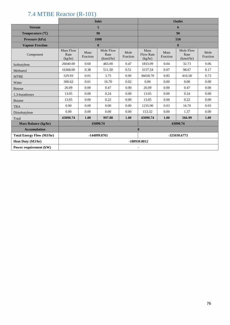
76
7.4 MTBE Reactor (R-101)
Inlet Outlet
Stream 5 6
Temperature (℃) 90 90
Pressure (kPa) 1000 550
Vapour Frection 0 0
Component
Mass Flow
Rate
(kg/hr)
Mass
Fraction
Mole Flow
Rate
(kmol/hr)
Mole
Fraction
Mass
Flow Rate
(kg/hr)
Mass
Fraction
Mole Flow
Rate
(kmol/hr)
Mole
Fraction
Isobutylene 26040.00 0.60 465.00 0.47 1833.09 0.04 32.73 0.06
Methanol 16368.00 0.38 511.50 0.51 3157.54 0.07 98.67 0.17
MTBE 329.93 0.01 3.75 0.00 36658.70 0.85 416.58 0.73
Water 300.62 0.01 16.70 0.02 0.00 0.00 0.00 0.00
Butene 26.09 0.00 0.47 0.00 26.09 0.00 0.47 0.00
1,3-butadienes 13.05 0.00 0.24 0.00 13.05 0.00 0.24 0.00
Butane 13.05 0.00 0.22 0.00 13.05 0.00 0.22 0.00
TBA 0.00 0.00 0.00 0.00 1235.90 0.03 16.70 0.03
Diisobutylene 0.00 0.00 0.00 0.00 153.32 0.00 1.37 0.00
Total 43090.74 1.00 997.88 1.00 43090.74 1.00 566.99 1.00
Mass Balance (kg/hr) 43090.74 43090.74
Accumulation 0
Total Energy Flow (MJ/hr) -144099.8761 -325030.6773
Heat Duty (MJ/hr) -180930.8012
Power requirement (kW) -
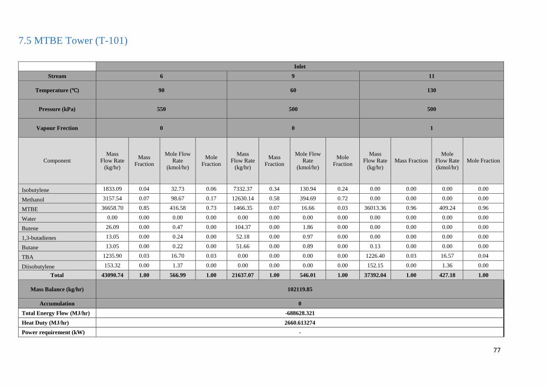
77
7.5 MTBE Tower (T-101)
Inlet
Stream 6 9 11
Temperature (℃) 90 60 130
Pressure (kPa) 550 500 500
Vapour Frection 0 0 1
Component
Mass
Flow Rate
(kg/hr)
Mass
Fraction
Mole Flow
Rate
(kmol/hr)
Mole
Fraction
Mass
Flow Rate
(kg/hr)
Mass
Fraction
Mole Flow
Rate
(kmol/hr)
Mole
Fraction
Mass
Flow Rate
(kg/hr)
Mass Fraction
Mole
Flow Rate
(kmol/hr)
Mole Fraction
Isobutylene 1833.09 0.04 32.73 0.06 7332.37 0.34 130.94 0.24 0.00 0.00 0.00 0.00
Methanol 3157.54 0.07 98.67 0.17 12630.14 0.58 394.69 0.72 0.00 0.00 0.00 0.00
MTBE 36658.70 0.85 416.58 0.73 1466.35 0.07 16.66 0.03 36013.36 0.96 409.24 0.96
Water 0.00 0.00 0.00 0.00 0.00 0.00 0.00 0.00 0.00 0.00 0.00 0.00
Butene 26.09 0.00 0.47 0.00 104.37 0.00 1.86 0.00 0.00 0.00 0.00 0.00
1,3-butadienes 13.05 0.00 0.24 0.00 52.18 0.00 0.97 0.00 0.00 0.00 0.00 0.00
Butane 13.05 0.00 0.22 0.00 51.66 0.00 0.89 0.00 0.13 0.00 0.00 0.00
TBA 1235.90 0.03 16.70 0.03 0.00 0.00 0.00 0.00 1226.40 0.03 16.57 0.04
Diisobutylene 153.32 0.00 1.37 0.00 0.00 0.00 0.00 0.00 152.15 0.00 1.36 0.00
Total 43090.74 1.00 566.99 1.00 21637.07 1.00 546.01 1.00 37392.04 1.00 427.18 1.00
Mass Balance (kg/hr) 102119.85
Accumulation 0
Total Energy Flow (MJ/hr) -688628.321
Heat Duty (MJ/hr) 2660.613274
Power requirement (kW) -
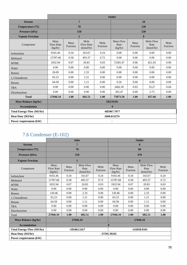
78
Outlet
Stream 7 10
Temperature (℃) 70 130
Pressure (kPa) 550 530
Vapour Frection 1 0
Component
Mass
Flow Rate
(kg/hr)
Mass
Fraction
Mole
Flow Rate
(kmol/hr)
Mole
Fraction
Mass Flow
Rate
(kg/hr)
Mass
Fraction
Mole Flow
Rate
(kmol/hr)
Mole
Fraction
Isobutylene 9165.46 0.34 163.67 0.24 0.00 0.00 0.00 0.00
Methanol 15787.68 0.58 493.37 0.72 0.00 0.00 0.00 0.00
MTBE 1832.94 0.07 20.83 0.03 72305.47 0.96 821.65 0.96
Water 0.00 0.00 0.00 0.00 0.00 0.00 0.00 0.00
Butene 26.09 0.00 2.33 0.00 0.00 0.00 0.00 0.00
1,3-butadienes 65.23 0.00 1.21 0.00 0.00 0.00 0.00 0.00
Butane 64.58 0.00 1.11 0.00 0.26 0.00 0.00 0.00
TBA 0.00 0.00 0.00 0.00 2462.30 0.03 33.27 0.04
Diisobutylene 0.00 0.00 0.00 0.00 305.47 0.00 2.73 0.00
Total 27046.34 1.00 682.51 1.00 75073.50 1.00 857.66 1.00
Mass Balance (kg/hr) 102119.85
Accumulation 0
Total Energy Flow (MJ/hr) -685967.7077
Heat Duty (MJ/hr) 2660.613274
Power requirement (kW) -
7.6 Condenser (E-102)
Inlet Outlet
Stream 7 8
Temperature (℃) 70 60
Pressure (kPa) 550 470
Vapour Frection 1 0
Component
Mass
Flow Rate
(kg/hr)
Mass
Fraction
Mole Flow
Rate
(kmol/hr)
Mole
Fraction
Mass
Flow Rate
(kg/hr)
Mass
Fraction
Mole Flow
Rate
(kmol/hr)
Mole
Fraction
Isobutylene 9165.46 0.34 163.67 0.24 9165.46 0.34 163.67 0.24
Methanol 15787.68 0.58 493.37 0.72 15787.68 0.58 493.37 0.72
MTBE 1832.94 0.07 20.83 0.03 1832.94 0.07 20.83 0.03
Water 0.00 0.00 0.00 0.00 0.00 0.00 0.00 0.00
Butene 130.46 0.00 2.33 0.00 130.46 0.00 2.33 0.00
1,3-butadienes 65.23 0.00 1.21 0.00 65.23 0.00 1.21 0.00
Butane 64.58 0.00 1.11 0.00 64.58 0.00 1.11 0.00
TBA 0.00 0.00 0.00 0.00 0.00 0.00 0.00 0.00
Diisobutylene 0.00 0.00 0.00 0.00 0.00 0.00 0.00 0.00
Total 27046.34 1.00 682.51 1.00 27046.34 1.00 682.51 1.00
Mass Balance (kg/hr) 27046.34 27046.34
Accumulation 0
Total Energy Flow (MJ/hr) -105463.5417 -143058.9341
Heat Duty (MJ/hr) -37595.39242
Power requirement (kW) -
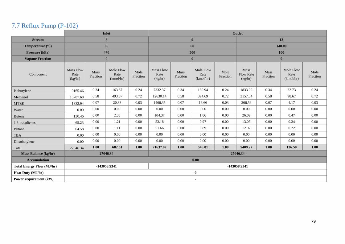
79
7.7 Reflux Pump (P-102)
Inlet Outlet
Stream 8 9 13
Temperature (℃) 60 60 140.00
Pressure (kPa) 470 500 100
Vapour Fraction 0 0 0
Component
Mass Flow
Rate
(kg/hr)
Mass
Fraction
Mole Flow
Rate
(kmol/hr)
Mole
Fraction
Mass Flow
Rate
(kg/hr)
Mass
Fraction
Mole Flow
Rate
(kmol/hr)
Mole
Fraction
Mass
Flow Rate
(kg/hr)
Mass
Fraction
Mole Flow
Rate
(kmol/hr)
Mole
Fraction
Isobutylene 9165.46 0.34 163.67 0.24 7332.37 0.34 130.94 0.24 1833.09 0.34 32.73 0.24
Methanol 15787.68 0.58 493.37 0.72 12630.14 0.58 394.69 0.72 3157.54 0.58 98.67 0.72
MTBE 1832.94 0.07 20.83 0.03 1466.35 0.07 16.66 0.03 366.59 0.07 4.17 0.03
Water 0.00 0.00 0.00 0.00 0.00 0.00 0.00 0.00 0.00 0.00 0.00 0.00
Butene 130.46 0.00 2.33 0.00 104.37 0.00 1.86 0.00 26.09 0.00 0.47 0.00
1,3-butadienes 65.23 0.00 1.21 0.00 52.18 0.00 0.97 0.00 13.05 0.00 0.24 0.00
Butane 64.58 0.00 1.11 0.00 51.66 0.00 0.89 0.00 12.92 0.00 0.22 0.00
TBA 0.00 0.00 0.00 0.00 0.00 0.00 0.00 0.00 0.00 0.00 0.00 0.00
Diisobutylene 0.00 0.00 0.00 0.00 0.00 0.00 0.00 0.00 0.00 0.00 0.00 0.00
Total 27046.34 1.00 682.51 1.00 21637.07 1.00 546.01 1.00 5409.27 1.00 136.50 1.00
Mass Balance (kg/hr) 27046.34 27046.34
Accumulation 0.00
Total Energy Flow (MJ/hr) -143058.9341 -143058.9341
Heat Duty (MJ/hr) 0
Power requirement (kW) -
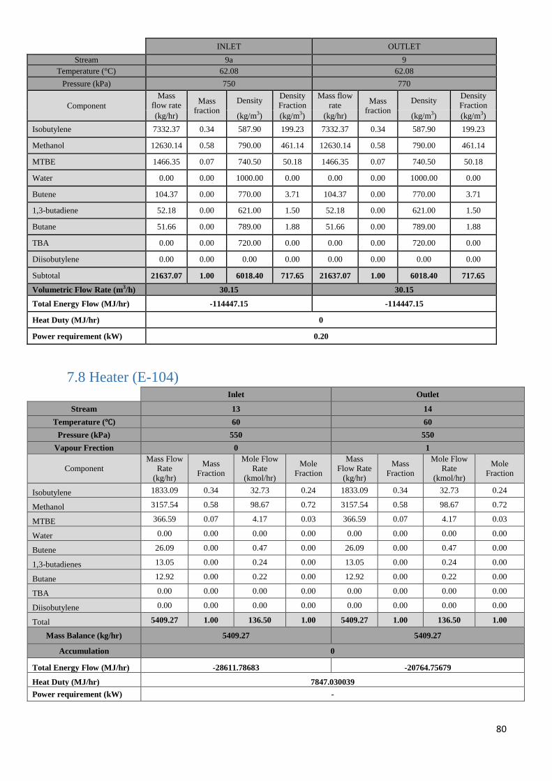
80
INLET OUTLET
Stream 9a 9
Temperature (°C) 62.08 62.08
Pressure (kPa) 750 770
Component
Mass
flow rate Mass
fraction
Density Density
Fraction
Mass flow
rate Mass
fraction
Density Density
Fraction
(kg/hr) (kg/m3) (kg/m3) (kg/hr) (kg/m3) (kg/m3)
Isobutylene 7332.37 0.34 587.90 199.23 7332.37 0.34 587.90 199.23
Methanol 12630.14 0.58 790.00 461.14 12630.14 0.58 790.00 461.14
MTBE 1466.35 0.07 740.50 50.18 1466.35 0.07 740.50 50.18
Water 0.00 0.00 1000.00 0.00 0.00 0.00 1000.00 0.00
Butene 104.37 0.00 770.00 3.71 104.37 0.00 770.00 3.71
1,3-butadiene 52.18 0.00 621.00 1.50 52.18 0.00 621.00 1.50
Butane 51.66 0.00 789.00 1.88 51.66 0.00 789.00 1.88
TBA 0.00 0.00 720.00 0.00 0.00 0.00 720.00 0.00
Diisobutylene 0.00 0.00 0.00 0.00 0.00 0.00 0.00 0.00
Subtotal 21637.07 1.00 6018.40 717.65 21637.07 1.00 6018.40 717.65
Volumetric Flow Rate (m3/h) 30.15 30.15
Total Energy Flow (MJ/hr) -114447.15 -114447.15
Heat Duty (MJ/hr) 0
Power requirement (kW) 0.20
7.8 Heater (E-104)
Inlet Outlet
Stream 13 14
Temperature (℃) 60 60
Pressure (kPa) 550 550
Vapour Frection 0 1
Component
Mass Flow
Rate
(kg/hr)
Mass
Fraction
Mole Flow
Rate
(kmol/hr)
Mole
Fraction
Mass
Flow Rate
(kg/hr)
Mass
Fraction
Mole Flow
Rate
(kmol/hr)
Mole
Fraction
Isobutylene 1833.09 0.34 32.73 0.24 1833.09 0.34 32.73 0.24
Methanol 3157.54 0.58 98.67 0.72 3157.54 0.58 98.67 0.72
MTBE 366.59 0.07 4.17 0.03 366.59 0.07 4.17 0.03
Water 0.00 0.00 0.00 0.00 0.00 0.00 0.00 0.00
Butene 26.09 0.00 0.47 0.00 26.09 0.00 0.47 0.00
1,3-butadienes 13.05 0.00 0.24 0.00 13.05 0.00 0.24 0.00
Butane 12.92 0.00 0.22 0.00 12.92 0.00 0.22 0.00
TBA 0.00 0.00 0.00 0.00 0.00 0.00 0.00 0.00
Diisobutylene 0.00 0.00 0.00 0.00 0.00 0.00 0.00 0.00
Total 5409.27 1.00 136.50 1.00 5409.27 1.00 136.50 1.00
Mass Balance (kg/hr) 5409.27 5409.27
Accumulation 0
Total Energy Flow (MJ/hr) -28611.78683 -20764.75679
Heat Duty (MJ/hr) 7847.030039
Power requirement (kW) -
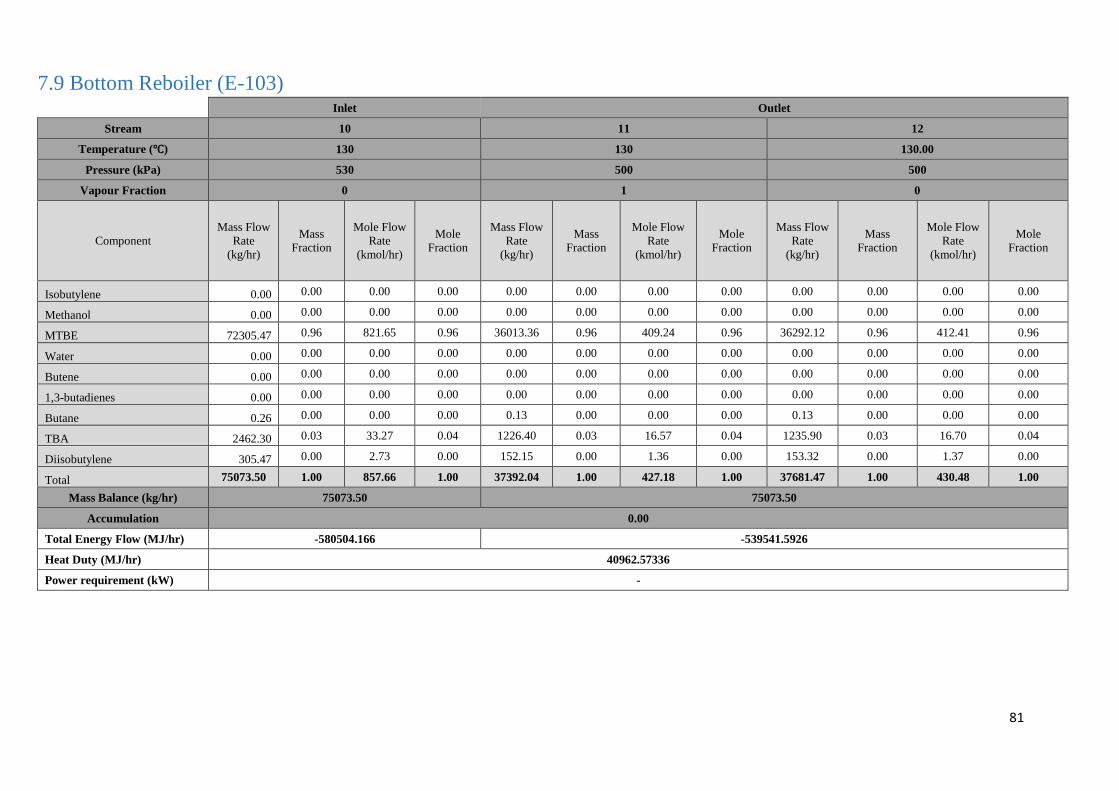
81
7.9 Bottom Reboiler (E-103)
Inlet Outlet
Stream 10 11 12
Temperature (℃) 130 130 130.00
Pressure (kPa) 530 500 500
Vapour Fraction 0 1 0
Component
Mass Flow
Rate
(kg/hr)
Mass
Fraction
Mole Flow
Rate
(kmol/hr)
Mole
Fraction
Mass Flow
Rate
(kg/hr)
Mass
Fraction
Mole Flow
Rate
(kmol/hr)
Mole
Fraction
Mass Flow
Rate
(kg/hr)
Mass
Fraction
Mole Flow
Rate
(kmol/hr)
Mole
Fraction
Isobutylene 0.00 0.00 0.00 0.00 0.00 0.00 0.00 0.00 0.00 0.00 0.00 0.00
Methanol 0.00 0.00 0.00 0.00 0.00 0.00 0.00 0.00 0.00 0.00 0.00 0.00
MTBE 72305.47 0.96 821.65 0.96 36013.36 0.96 409.24 0.96 36292.12 0.96 412.41 0.96
Water 0.00 0.00 0.00 0.00 0.00 0.00 0.00 0.00 0.00 0.00 0.00 0.00
Butene 0.00 0.00 0.00 0.00 0.00 0.00 0.00 0.00 0.00 0.00 0.00 0.00
1,3-butadienes 0.00 0.00 0.00 0.00 0.00 0.00 0.00 0.00 0.00 0.00 0.00 0.00
Butane 0.26 0.00 0.00 0.00 0.13 0.00 0.00 0.00 0.13 0.00 0.00 0.00
TBA 2462.30 0.03 33.27 0.04 1226.40 0.03 16.57 0.04 1235.90 0.03 16.70 0.04
Diisobutylene 305.47 0.00 2.73 0.00 152.15 0.00 1.36 0.00 153.32 0.00 1.37 0.00
Total 75073.50 1.00 857.66 1.00 37392.04 1.00 427.18 1.00 37681.47 1.00 430.48 1.00
Mass Balance (kg/hr) 75073.50 75073.50
Accumulation 0.00
Total Energy Flow (MJ/hr) -580504.166 -539541.5926
Heat Duty (MJ/hr) 40962.57336
Power requirement (kW) -
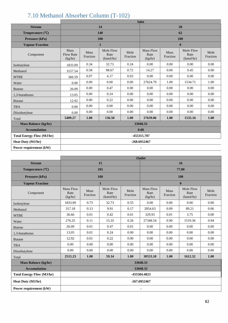
82
7.10 Methanol Absorber Column (T-102)
Inlet
Stream 14 28
Temperature (℃) 140 62
Pressure (kPa) 100 100
Vapour Fraction 1 0
Component
Mass
Flow Rate
(kg/hr)
Mass
Fraction
Mole Flow
Rate
(kmol/hr)
Mole
Fraction
Mass Flow
Rate
(kg/hr)
Mass
Fraction
Mole Flow
Rate
(kmol/hr)
Mole
Fraction
Isobutylene 1833.09 0.34 32.73 0.24 0.00 0.00 0.00 0.00
Methanol 3157.54 0.58 98.67 0.72 14.27 0.00 0.45 0.00
MTBE 366.59 0.07 4.17 0.03 0.00 0.00 0.00 0.00
Water 0.00 0.00 0.00 0.00 27624.79 1.00 1534.71 1.00
Butene 26.09 0.00 0.47 0.00 0.00 0.00 0.00 0.00
1,3-butadienes 13.05 0.00 0.24 0.00 0.00 0.00 0.00 0.00
Butane 12.92 0.00 0.22 0.00 0.00 0.00 0.00 0.00
TBA 0.00 0.00 0.00 0.00 0.00 0.00 0.00 0.00
Diisobutylene 0.00 0.00 0.00 0.00 0.00 0.00 0.00 0.00
Total 5409.27 1.00 136.50 1.00 27639.06 1.00 1535.16 1.00
Mass Balance (kg/hr) 33048.33
Accumulation 0.00
Total Energy Flow (MJ/hr) -455315.787
Heat Duty (MJ/hr) -268.6952467
Power requirement (kW) -
Outlet
Stream 15 16
Temperature (℃) 105 77.00
Pressure (kPa) 100 100
Vapour Fraction 1 0
Component
Mass Flow
Rate
(kg/hr)
Mass
Fraction
Mole Flow
Rate
(kmol/hr)
Mole
Fraction
Mass Flow
Rate
(kg/hr)
Mass
Fraction
Mole Flow
Rate
(kmol/hr)
Mole
Fraction
Isobutylene 1833.09 0.73 32.73 0.55 0.00 0.00 0.00 0.00
Methanol 317.18 0.13 9.91 0.17 2854.63 0.09 89.21 0.06
MTBE 36.66 0.01 0.42 0.01 329.93 0.01 3.75 0.00
Water 276.25 0.11 15.35 0.26 27348.54 0.90 1519.36 0.94
Butene 26.09 0.01 0.47 0.01 0.00 0.00 0.00 0.00
1,3-butadienes 13.05 0.01 0.24 0.00 0.00 0.00 0.00 0.00
Butane 12.92 0.01 0.22 0.00 0.00 0.00 0.00 0.00
TBA 0.00 0.00 0.00 0.00 0.00 0.00 0.00 0.00
Diisobutylene 0.00 0.00 0.00 0.00 0.00 0.00 0.00 0.00
Total 2515.23 1.00 59.34 1.00 30533.10 1.00 1612.32 1.00
Mass Balance (kg/hr) 33048.33
Accumulation 33048.33
Total Energy Flow (MJ/hr) -455584.4823
Heat Duty (MJ/hr) -267.6952467
Power requirement (kW) -
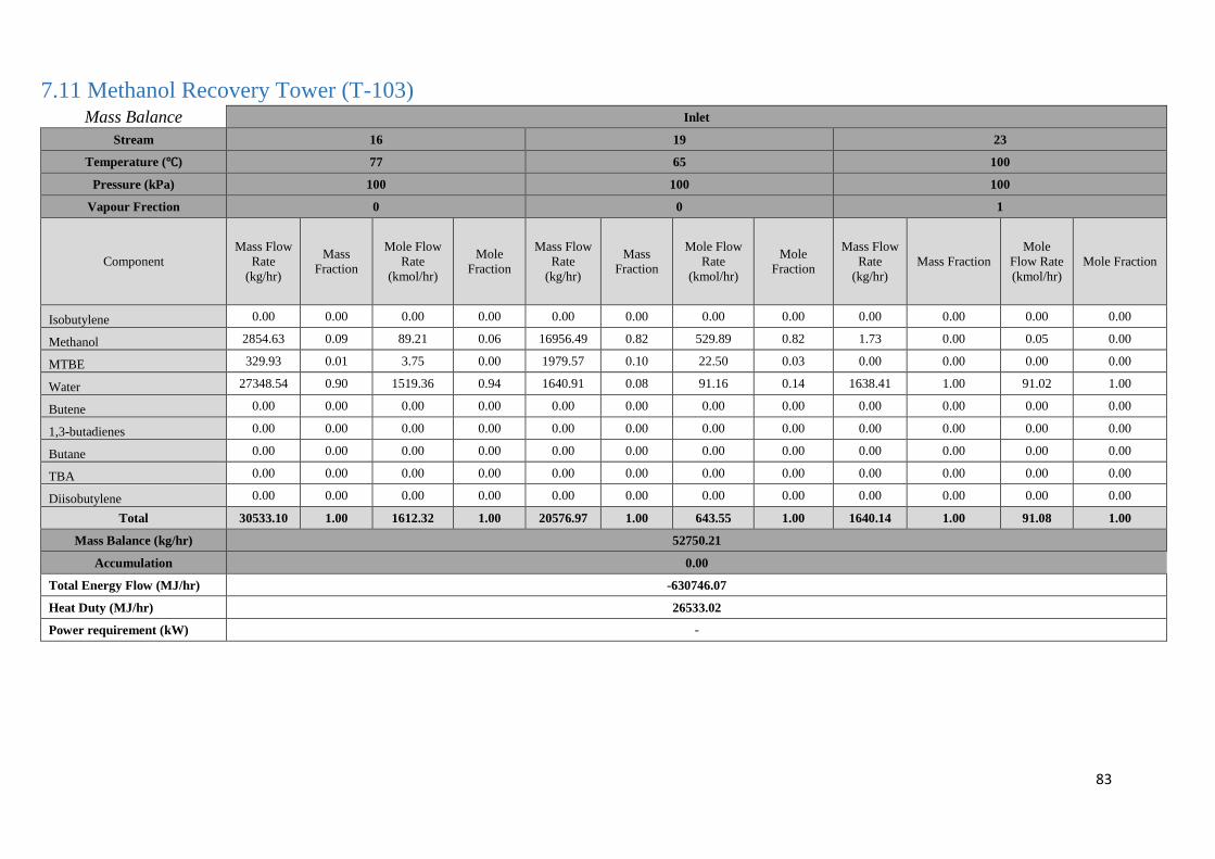
83
7.11 Methanol Recovery Tower (T-103) Mass Balance Inlet
Stream 16 19 23
Temperature (℃) 77 65 100
Pressure (kPa) 100 100 100
Vapour Frection 0 0 1
Component
Mass Flow
Rate
(kg/hr)
Mass
Fraction
Mole Flow
Rate
(kmol/hr)
Mole
Fraction
Mass Flow
Rate
(kg/hr)
Mass
Fraction
Mole Flow
Rate
(kmol/hr)
Mole
Fraction
Mass Flow
Rate
(kg/hr)
Mass Fraction
Mole
Flow Rate
(kmol/hr)
Mole Fraction
Isobutylene 0.00 0.00 0.00 0.00 0.00 0.00 0.00 0.00 0.00 0.00 0.00 0.00
Methanol 2854.63 0.09 89.21 0.06 16956.49 0.82 529.89 0.82 1.73 0.00 0.05 0.00
MTBE 329.93 0.01 3.75 0.00 1979.57 0.10 22.50 0.03 0.00 0.00 0.00 0.00
Water 27348.54 0.90 1519.36 0.94 1640.91 0.08 91.16 0.14 1638.41 1.00 91.02 1.00
Butene 0.00 0.00 0.00 0.00 0.00 0.00 0.00 0.00 0.00 0.00 0.00 0.00
1,3-butadienes 0.00 0.00 0.00 0.00 0.00 0.00 0.00 0.00 0.00 0.00 0.00 0.00
Butane 0.00 0.00 0.00 0.00 0.00 0.00 0.00 0.00 0.00 0.00 0.00 0.00
TBA 0.00 0.00 0.00 0.00 0.00 0.00 0.00 0.00 0.00 0.00 0.00 0.00
Diisobutylene 0.00 0.00 0.00 0.00 0.00 0.00 0.00 0.00 0.00 0.00 0.00 0.00
Total 30533.10 1.00 1612.32 1.00 20576.97 1.00 643.55 1.00 1640.14 1.00 91.08 1.00
Mass Balance (kg/hr) 52750.21
Accumulation 0.00
Total Energy Flow (MJ/hr) -630746.07
Heat Duty (MJ/hr) 26533.02
Power requirement (kW) -
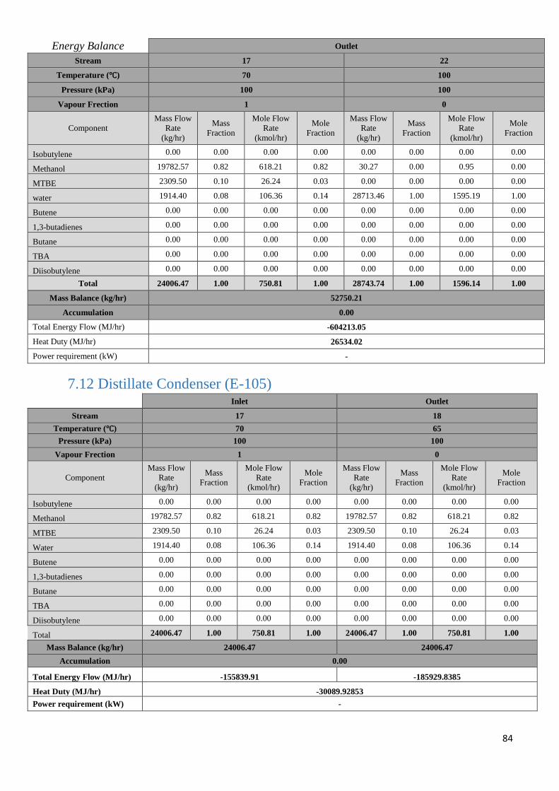
84
Energy Balance Outlet
Stream 17 22
Temperature (℃) 70 100
Pressure (kPa) 100 100
Vapour Frection 1 0
Component
Mass Flow
Rate
(kg/hr)
Mass
Fraction
Mole Flow
Rate
(kmol/hr)
Mole
Fraction
Mass Flow
Rate
(kg/hr)
Mass
Fraction
Mole Flow
Rate
(kmol/hr)
Mole
Fraction
Isobutylene 0.00 0.00 0.00 0.00 0.00 0.00 0.00 0.00
Methanol 19782.57 0.82 618.21 0.82 30.27 0.00 0.95 0.00
MTBE 2309.50 0.10 26.24 0.03 0.00 0.00 0.00 0.00
water 1914.40 0.08 106.36 0.14 28713.46 1.00 1595.19 1.00
Butene 0.00 0.00 0.00 0.00 0.00 0.00 0.00 0.00
1,3-butadienes 0.00 0.00 0.00 0.00 0.00 0.00 0.00 0.00
Butane 0.00 0.00 0.00 0.00 0.00 0.00 0.00 0.00
TBA 0.00 0.00 0.00 0.00 0.00 0.00 0.00 0.00
Diisobutylene 0.00 0.00 0.00 0.00 0.00 0.00 0.00 0.00
Total 24006.47 1.00 750.81 1.00 28743.74 1.00 1596.14 1.00
Mass Balance (kg/hr) 52750.21
Accumulation 0.00
Total Energy Flow (MJ/hr) -604213.05
Heat Duty (MJ/hr) 26534.02
Power requirement (kW) -
7.12 Distillate Condenser (E-105)
Inlet Outlet
Stream 17 18
Temperature (℃) 70 65
Pressure (kPa) 100 100
Vapour Frection 1 0
Component
Mass Flow
Rate
(kg/hr)
Mass
Fraction
Mole Flow
Rate
(kmol/hr)
Mole
Fraction
Mass Flow
Rate
(kg/hr)
Mass
Fraction
Mole Flow
Rate
(kmol/hr)
Mole
Fraction
Isobutylene 0.00 0.00 0.00 0.00 0.00 0.00 0.00 0.00
Methanol 19782.57 0.82 618.21 0.82 19782.57 0.82 618.21 0.82
MTBE 2309.50 0.10 26.24 0.03 2309.50 0.10 26.24 0.03
Water 1914.40 0.08 106.36 0.14 1914.40 0.08 106.36 0.14
Butene 0.00 0.00 0.00 0.00 0.00 0.00 0.00 0.00
1,3-butadienes 0.00 0.00 0.00 0.00 0.00 0.00 0.00 0.00
Butane 0.00 0.00 0.00 0.00 0.00 0.00 0.00 0.00
TBA 0.00 0.00 0.00 0.00 0.00 0.00 0.00 0.00
Diisobutylene 0.00 0.00 0.00 0.00 0.00 0.00 0.00 0.00
Total 24006.47 1.00 750.81 1.00 24006.47 1.00 750.81 1.00
Mass Balance (kg/hr) 24006.47 24006.47
Accumulation 0.00
Total Energy Flow (MJ/hr) -155839.91 -185929.8385
Heat Duty (MJ/hr) -30089.92853
Power requirement (kW) -
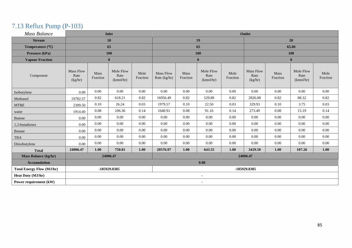
85
7.13 Reflux Pump (P-103) Mass Balance Inlet Outlet
Stream 18 19 20
Temperature (℃) 65 65 65.00
Pressure (kPa) 100 100 100
Vapour Fraction 0 0 0
Component
Mass Flow
Rate
(kg/hr)
Mass
Fraction
Mole Flow
Rate
(kmol/hr)
Mole
Fraction
Mass Flow
Rate (kg/hr)
Mass
Fraction
Mole Flow
Rate
(kmol/hr)
Mole
Fraction
Mass Flow
Rate
(kg/hr)
Mass
Fraction
Mole Flow
Rate
(kmol/hr)
Mole
Fraction
Isobutylene 0.00 0.00 0.00 0.00 0.00 0.00 0.00 0.00 0.00 0.00 0.00 0.00
Methanol 19782.57 0.82 618.21 0.82 16956.49 0.82 529.89 0.82 2826.08 0.82 88.32 0.82
MTBE 2309.50 0.10 26.24 0.03 1979.57 0.10 22.50 0.03 329.93 0.10 3.75 0.03
water 1914.40 0.08 106.36 0.14 1640.91 0.08 91.16 0.14 273.49 0.08 15.19 0.14
Butene 0.00 0.00 0.00 0.00 0.00 0.00 0.00 0.00 0.00 0.00 0.00 0.00
1,3-butadienes 0.00 0.00 0.00 0.00 0.00 0.00 0.00 0.00 0.00 0.00 0.00 0.00
Butane 0.00 0.00 0.00 0.00 0.00 0.00 0.00 0.00 0.00 0.00 0.00 0.00
TBA 0.00 0.00 0.00 0.00 0.00 0.00 0.00 0.00 0.00 0.00 0.00 0.00
Diisobutylene 0.00 0.00 0.00 0.00 0.00 0.00 0.00 0.00 0.00 0.00 0.00 0.00
Total 24006.47 1.00 750.81 1.00 20576.97 1.00 643.55 1.00 3429.50 1.00 107.26 1.00
Mass Balance (kg/hr) 24006.47 24006.47
Accumulation 0.00
Total Energy Flow (MJ/hr) -185929.8385 -185929.8385
Heat Duty (MJ/hr) -
Power requirement (kW) -
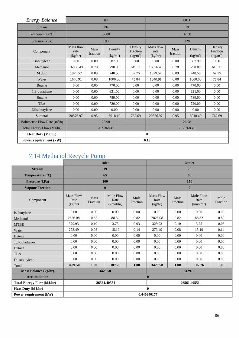
86
Energy Balance IN OUT
Stream 19a 19
Temperature (°C) 32.88 32.88
Pressure (kPa) 100 120
Component
Mass flow
rate Mass
fraction
Density Density
Fraction
Mass flow
rate Mass
fraction
Density Density
Fraction
(kg/hr) (kg/m3) (kg/m3) (kg/hr) (kg/m3) (kg/m3)
Isobutylene 0.00 0.00 587.90 0.00 0.00 0.00 587.90 0.00
Methanol 16956.49 0.78 790.00 619.11 16956.49 0.78 790.00 619.11
MTBE 1979.57 0.09 740.50 67.75 1979.57 0.09 740.50 67.75
Water 1640.91 0.08 1000.00 75.84 1640.91 0.08 1000.00 75.84
Butene 0.00 0.00 770.00 0.00 0.00 0.00 770.00 0.00
1,3-butadiene 0.00 0.00 621.00 0.00 0.00 0.00 621.00 0.00
Butane 0.00 0.00 789.00 0.00 0.00 0.00 789.00 0.00
TBA 0.00 0.00 720.00 0.00 0.00 0.00 720.00 0.00
Diisobutylene 0.00 0.00 0.00 0.00 0.00 0.00 0.00 0.00
Subtotal 20576.97 0.95 6018.40 762.69 20576.97 0.95 6018.40 762.69
Volumetric Flow Rate (m3/h) 26.98 26.98
Total Energy Flow (MJ/hr) -159368.43 -159368.43
Heat Duty (MJ/hr) 0
Power requirement (kW) 0.18
7.14 Methanol Recycle Pump
Inlet Outlet
Stream 19 20
Temperature (℃) 65 60
Pressure (kPa) 100 150
Vapour Frection 0 0
Component
Mass Flow
Rate
(kg/hr)
Mass
Fraction
Mole Flow
Rate
(kmol/hr)
Mole
Fraction
Mass Flow
Rate
(kg/hr)
Mass
Fraction
Mole Flow
Rate
(kmol/hr)
Mole
Fraction
Isobutylene 0.00 0.00 0.00 0.00 0.00 0.00 0.00 0.00
Methanol 2826.08 0.82 88.32 0.82 2826.08 0.82 88.32 0.82
MTBE 329.93 0.10 3.75 0.03 329.93 0.10 3.75 0.03
Water 273.49 0.08 15.19 0.14 273.49 0.08 15.19 0.14
Butene 0.00 0.00 0.00 0.00 0.00 0.00 0.00 0.00
1,3-butadienes 0.00 0.00 0.00 0.00 0.00 0.00 0.00 0.00
Butane 0.00 0.00 0.00 0.00 0.00 0.00 0.00 0.00
TBA 0.00 0.00 0.00 0.00 0.00 0.00 0.00 0.00
Diisobutylene 0.00 0.00 0.00 0.00 0.00 0.00 0.00 0.00
Total 3429.50 1.00 107.26 1.00 3429.50 1.00 107.26 1.00
Mass Balance (kg/hr) 3429.50 3429.50
Accumulation 0
Total Energy Flow (MJ/hr) -26561.40551 -26561.40551
Heat Duty (MJ/hr) 0
Power requirement (kW) 0.440840177
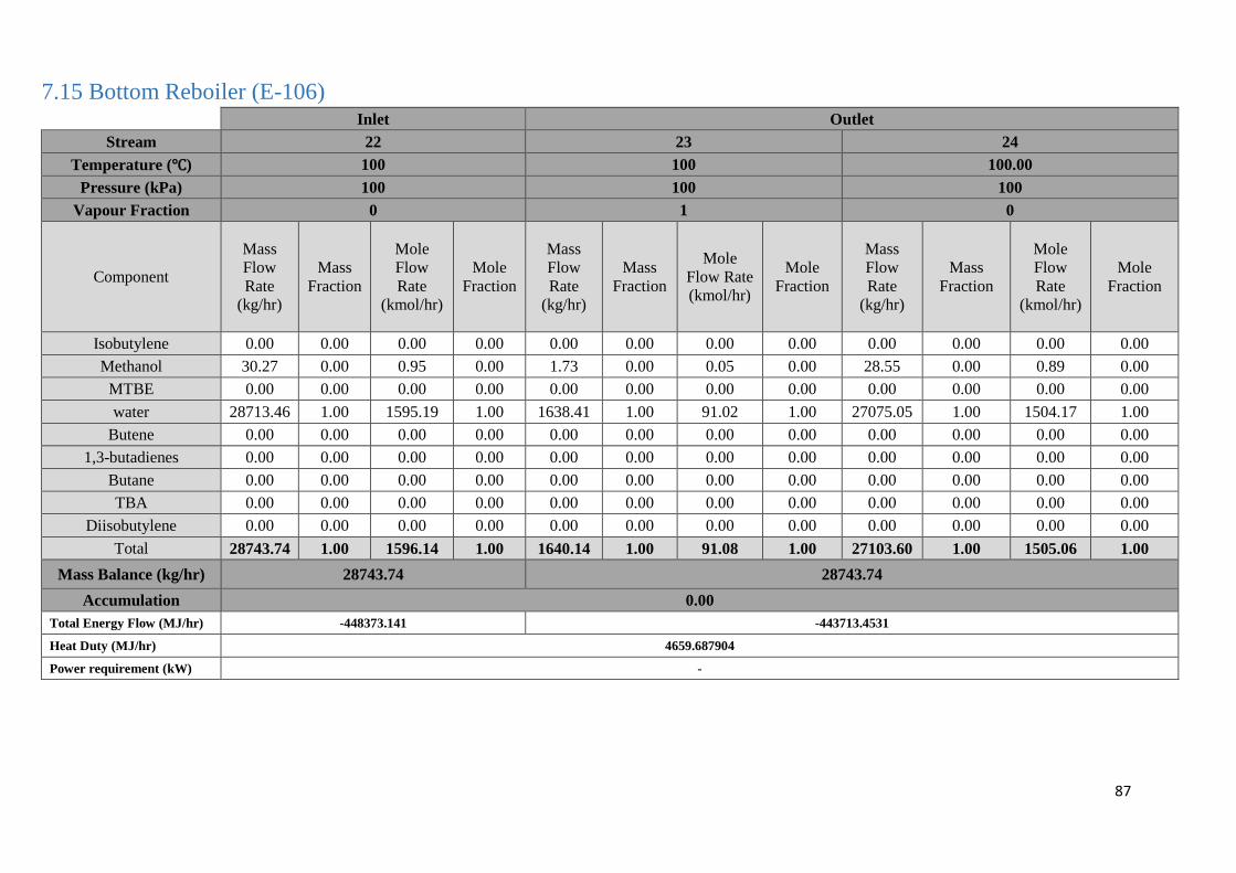
87
7.15 Bottom Reboiler (E-106)
Inlet Outlet
Stream 22 23 24
Temperature (℃) 100 100 100.00
Pressure (kPa) 100 100 100
Vapour Fraction 0 1 0
Component
Mass
Flow
Rate
(kg/hr)
Mass
Fraction
Mole
Flow
Rate
(kmol/hr)
Mole
Fraction
Mass
Flow
Rate
(kg/hr)
Mass
Fraction
Mole
Flow Rate
(kmol/hr)
Mole
Fraction
Mass
Flow
Rate
(kg/hr)
Mass
Fraction
Mole
Flow
Rate
(kmol/hr)
Mole
Fraction
Isobutylene 0.00 0.00 0.00 0.00 0.00 0.00 0.00 0.00 0.00 0.00 0.00 0.00
Methanol 30.27 0.00 0.95 0.00 1.73 0.00 0.05 0.00 28.55 0.00 0.89 0.00
MTBE 0.00 0.00 0.00 0.00 0.00 0.00 0.00 0.00 0.00 0.00 0.00 0.00
water 28713.46 1.00 1595.19 1.00 1638.41 1.00 91.02 1.00 27075.05 1.00 1504.17 1.00
Butene 0.00 0.00 0.00 0.00 0.00 0.00 0.00 0.00 0.00 0.00 0.00 0.00
1,3-butadienes 0.00 0.00 0.00 0.00 0.00 0.00 0.00 0.00 0.00 0.00 0.00 0.00
Butane 0.00 0.00 0.00 0.00 0.00 0.00 0.00 0.00 0.00 0.00 0.00 0.00
TBA 0.00 0.00 0.00 0.00 0.00 0.00 0.00 0.00 0.00 0.00 0.00 0.00
Diisobutylene 0.00 0.00 0.00 0.00 0.00 0.00 0.00 0.00 0.00 0.00 0.00 0.00
Total 28743.74 1.00 1596.14 1.00 1640.14 1.00 91.08 1.00 27103.60 1.00 1505.06 1.00
Mass Balance (kg/hr) 28743.74 28743.74
Accumulation 0.00
Total Energy Flow (MJ/hr) -448373.141 -443713.4531
Heat Duty (MJ/hr) 4659.687904
Power requirement (kW) -
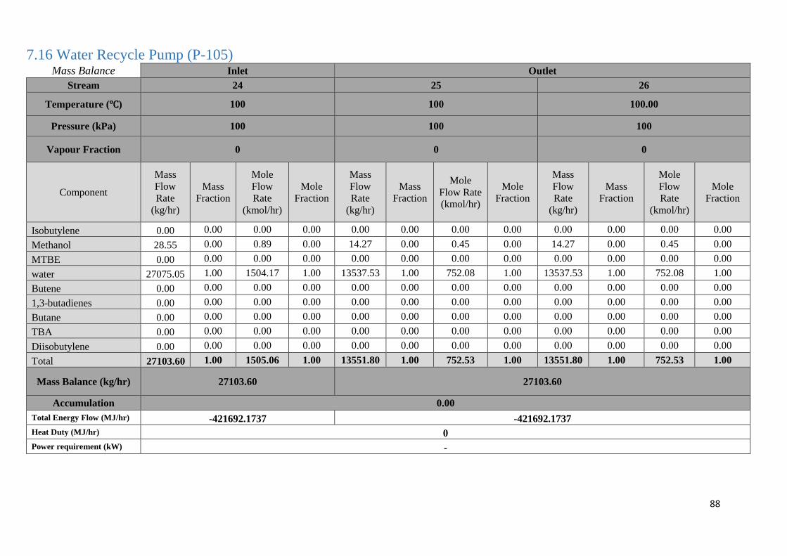
88
7.16 Water Recycle Pump (P-105) Mass Balance Inlet Outlet
Stream 24 25 26
Temperature (℃) 100 100 100.00
Pressure (kPa) 100 100 100
Vapour Fraction 0 0 0
Component
Mass
Flow
Rate
(kg/hr)
Mass
Fraction
Mole
Flow
Rate
(kmol/hr)
Mole
Fraction
Mass
Flow
Rate
(kg/hr)
Mass
Fraction
Mole
Flow Rate
(kmol/hr)
Mole
Fraction
Mass
Flow
Rate
(kg/hr)
Mass
Fraction
Mole
Flow
Rate
(kmol/hr)
Mole
Fraction
Isobutylene 0.00 0.00 0.00 0.00 0.00 0.00 0.00 0.00 0.00 0.00 0.00 0.00
Methanol 28.55 0.00 0.89 0.00 14.27 0.00 0.45 0.00 14.27 0.00 0.45 0.00
MTBE 0.00 0.00 0.00 0.00 0.00 0.00 0.00 0.00 0.00 0.00 0.00 0.00
water 27075.05 1.00 1504.17 1.00 13537.53 1.00 752.08 1.00 13537.53 1.00 752.08 1.00
Butene 0.00 0.00 0.00 0.00 0.00 0.00 0.00 0.00 0.00 0.00 0.00 0.00
1,3-butadienes 0.00 0.00 0.00 0.00 0.00 0.00 0.00 0.00 0.00 0.00 0.00 0.00
Butane 0.00 0.00 0.00 0.00 0.00 0.00 0.00 0.00 0.00 0.00 0.00 0.00
TBA 0.00 0.00 0.00 0.00 0.00 0.00 0.00 0.00 0.00 0.00 0.00 0.00
Diisobutylene 0.00 0.00 0.00 0.00 0.00 0.00 0.00 0.00 0.00 0.00 0.00 0.00
Total 27103.60 1.00 1505.06 1.00 13551.80 1.00 752.53 1.00 13551.80 1.00 752.53 1.00
Mass Balance (kg/hr) 27103.60 27103.60
Accumulation 0.00
Total Energy Flow (MJ/hr) -421692.1737 -421692.1737
Heat Duty (MJ/hr) 0
Power requirement (kW) -
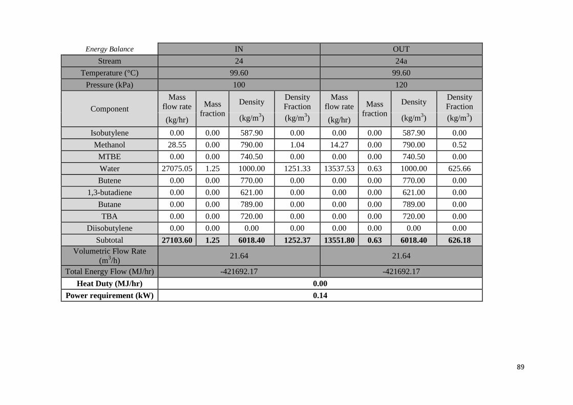
89
Energy Balance IN OUT
Stream 24 24a
Temperature (°C) 99.60 99.60
Pressure (kPa) 100 120
Component
Mass
flow rate Mass
fraction
Density Density
Fraction
Mass
flow rate Mass
fraction
Density Density
Fraction
(kg/hr) (kg/m3) (kg/m
3) (kg/hr) (kg/m
3) (kg/m
3)
Isobutylene 0.00 0.00 587.90 0.00 0.00 0.00 587.90 0.00
Methanol 28.55 0.00 790.00 1.04 14.27 0.00 790.00 0.52
MTBE 0.00 0.00 740.50 0.00 0.00 0.00 740.50 0.00
Water 27075.05 1.25 1000.00 1251.33 13537.53 0.63 1000.00 625.66
Butene 0.00 0.00 770.00 0.00 0.00 0.00 770.00 0.00
1,3-butadiene 0.00 0.00 621.00 0.00 0.00 0.00 621.00 0.00
Butane 0.00 0.00 789.00 0.00 0.00 0.00 789.00 0.00
TBA 0.00 0.00 720.00 0.00 0.00 0.00 720.00 0.00
Diisobutylene 0.00 0.00 0.00 0.00 0.00 0.00 0.00 0.00
Subtotal 27103.60 1.25 6018.40 1252.37 13551.80 0.63 6018.40 626.18
Volumetric Flow Rate
(m3/h)
21.64 21.64
Total Energy Flow (MJ/hr) -421692.17 -421692.17
Heat Duty (MJ/hr) 0.00
Power requirement (kW) 0.14
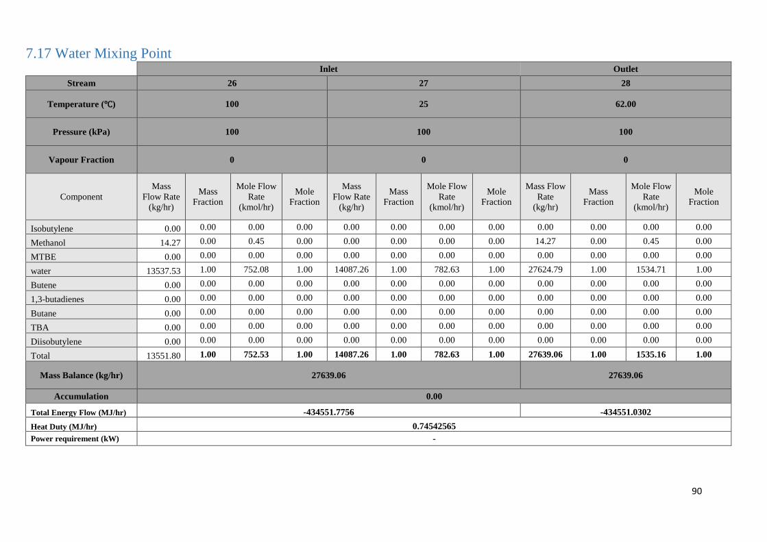
90
7.17 Water Mixing Point
Inlet Outlet
Stream 26 27 28
Temperature (℃) 100 25 62.00
Pressure (kPa) 100 100 100
Vapour Fraction 0 0 0
Component
Mass
Flow Rate
(kg/hr)
Mass
Fraction
Mole Flow
Rate
(kmol/hr)
Mole
Fraction
Mass
Flow Rate
(kg/hr)
Mass
Fraction
Mole Flow
Rate
(kmol/hr)
Mole
Fraction
Mass Flow
Rate
(kg/hr)
Mass
Fraction
Mole Flow
Rate
(kmol/hr)
Mole
Fraction
Isobutylene 0.00 0.00 0.00 0.00 0.00 0.00 0.00 0.00 0.00 0.00 0.00 0.00
Methanol 14.27 0.00 0.45 0.00 0.00 0.00 0.00 0.00 14.27 0.00 0.45 0.00
MTBE 0.00 0.00 0.00 0.00 0.00 0.00 0.00 0.00 0.00 0.00 0.00 0.00
water 13537.53 1.00 752.08 1.00 14087.26 1.00 782.63 1.00 27624.79 1.00 1534.71 1.00
Butene 0.00 0.00 0.00 0.00 0.00 0.00 0.00 0.00 0.00 0.00 0.00 0.00
1,3-butadienes 0.00 0.00 0.00 0.00 0.00 0.00 0.00 0.00 0.00 0.00 0.00 0.00
Butane 0.00 0.00 0.00 0.00 0.00 0.00 0.00 0.00 0.00 0.00 0.00 0.00
TBA 0.00 0.00 0.00 0.00 0.00 0.00 0.00 0.00 0.00 0.00 0.00 0.00
Diisobutylene 0.00 0.00 0.00 0.00 0.00 0.00 0.00 0.00 0.00 0.00 0.00 0.00
Total 13551.80 1.00 752.53 1.00 14087.26 1.00 782.63 1.00 27639.06 1.00 1535.16 1.00
Mass Balance (kg/hr) 27639.06 27639.06
Accumulation 0.00
Total Energy Flow (MJ/hr) -434551.7756 -434551.0302
Heat Duty (MJ/hr) 0.74542565
Power requirement (kW) -
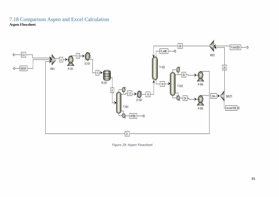
91
7.18 Comparison Aspen and Excel Calculation Aspen Flowsheet
Figure 29: Aspen Flowsheet
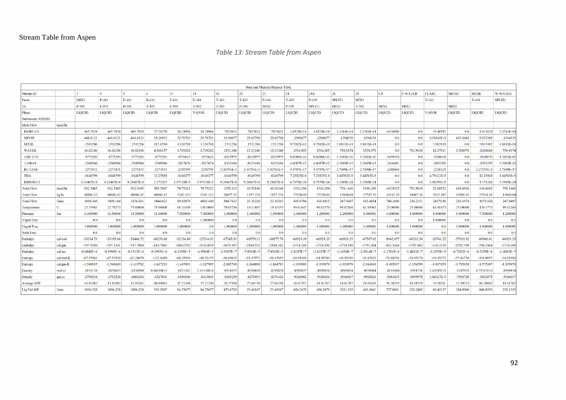
92
Stream Table from Aspen
Table 13: Stream Table from Aspen
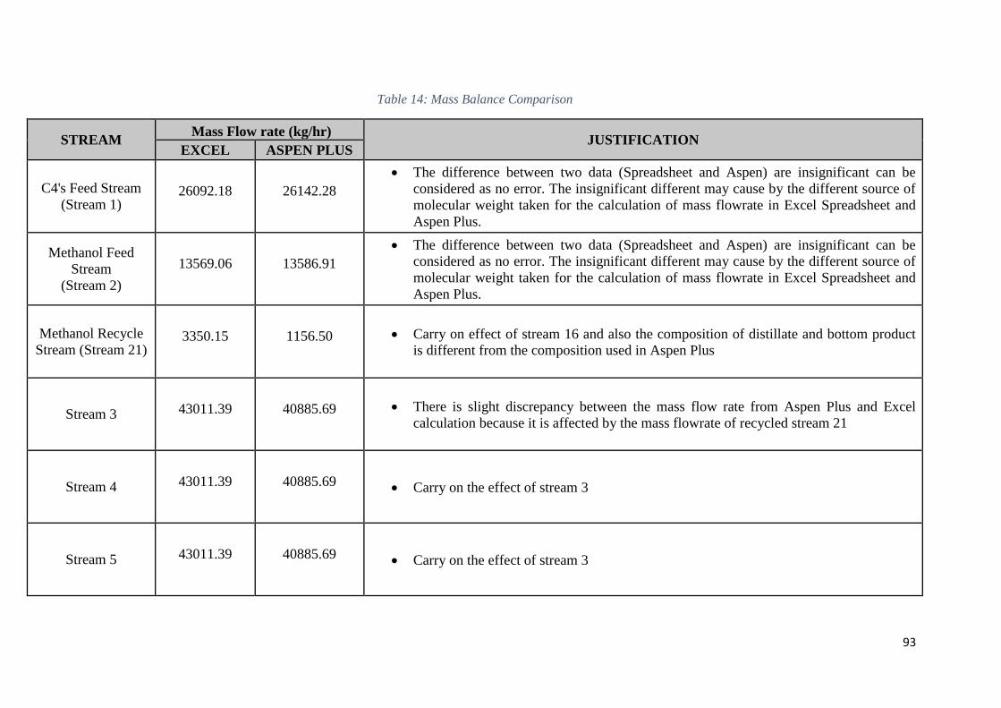
93
Table 14: Mass Balance Comparison
STREAM Mass Flow rate (kg/hr)
JUSTIFICATION EXCEL ASPEN PLUS
C4's Feed Stream
(Stream 1) 26092.18 26142.28
The difference between two data (Spreadsheet and Aspen) are insignificant can be
considered as no error. The insignificant different may cause by the different source of
molecular weight taken for the calculation of mass flowrate in Excel Spreadsheet and
Aspen Plus.
Methanol Feed
Stream
(Stream 2)
13569.06 13586.91
The difference between two data (Spreadsheet and Aspen) are insignificant can be
considered as no error. The insignificant different may cause by the different source of
molecular weight taken for the calculation of mass flowrate in Excel Spreadsheet and
Aspen Plus.
Methanol Recycle
Stream (Stream 21) 3350.15 1156.50 Carry on effect of stream 16 and also the composition of distillate and bottom product
is different from the composition used in Aspen Plus
Stream 3 43011.39 40885.69 There is slight discrepancy between the mass flow rate from Aspen Plus and Excel
calculation because it is affected by the mass flowrate of recycled stream 21
Stream 4 43011.39 40885.69 Carry on the effect of stream 3
Stream 5 43011.39 40885.69 Carry on the effect of stream 3
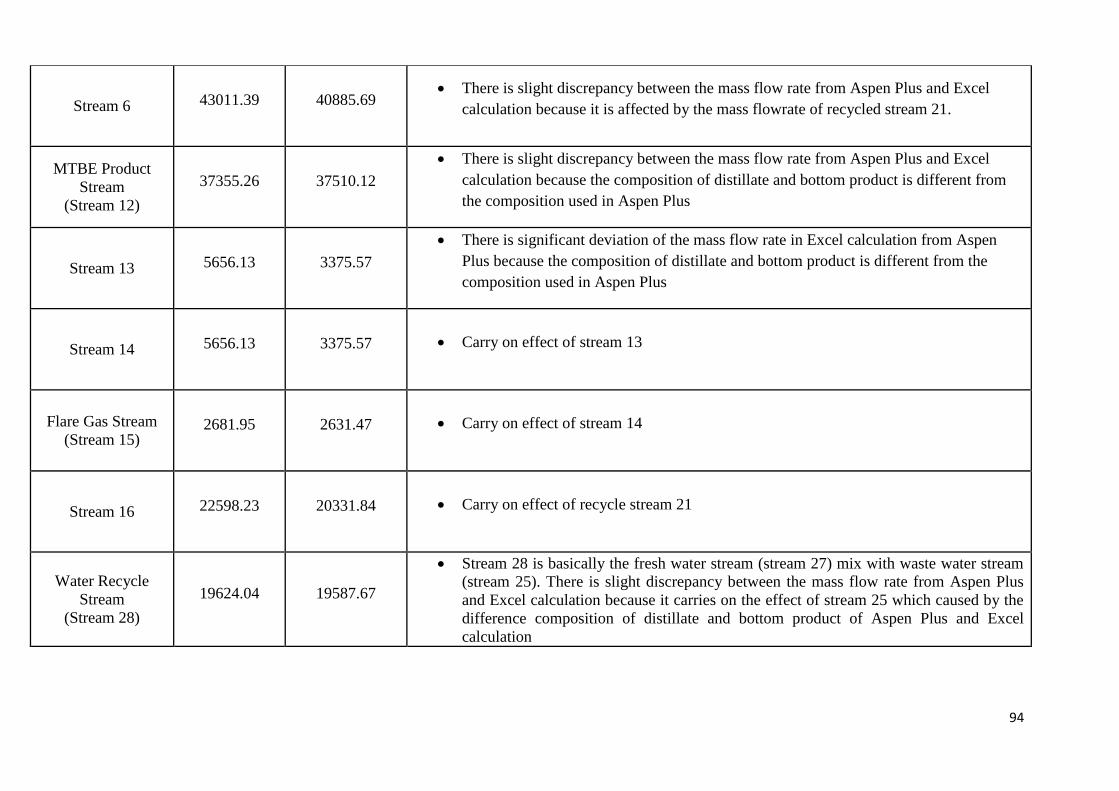
94
Stream 6 43011.39 40885.69 There is slight discrepancy between the mass flow rate from Aspen Plus and Excel
calculation because it is affected by the mass flowrate of recycled stream 21.
MTBE Product
Stream
(Stream 12)
37355.26 37510.12
There is slight discrepancy between the mass flow rate from Aspen Plus and Excel
calculation because the composition of distillate and bottom product is different from
the composition used in Aspen Plus
Stream 13 5656.13 3375.57
There is significant deviation of the mass flow rate in Excel calculation from Aspen
Plus because the composition of distillate and bottom product is different from the
composition used in Aspen Plus
Stream 14 5656.13 3375.57 Carry on effect of stream 13
Flare Gas Stream
(Stream 15) 2681.95 2631.47 Carry on effect of stream 14
Stream 16 22598.23 20331.84 Carry on effect of recycle stream 21
Water Recycle
Stream
(Stream 28)
19624.04 19587.67
Stream 28 is basically the fresh water stream (stream 27) mix with waste water stream
(stream 25). There is slight discrepancy between the mass flow rate from Aspen Plus
and Excel calculation because it carries on the effect of stream 25 which caused by the
difference composition of distillate and bottom product of Aspen Plus and Excel
calculation
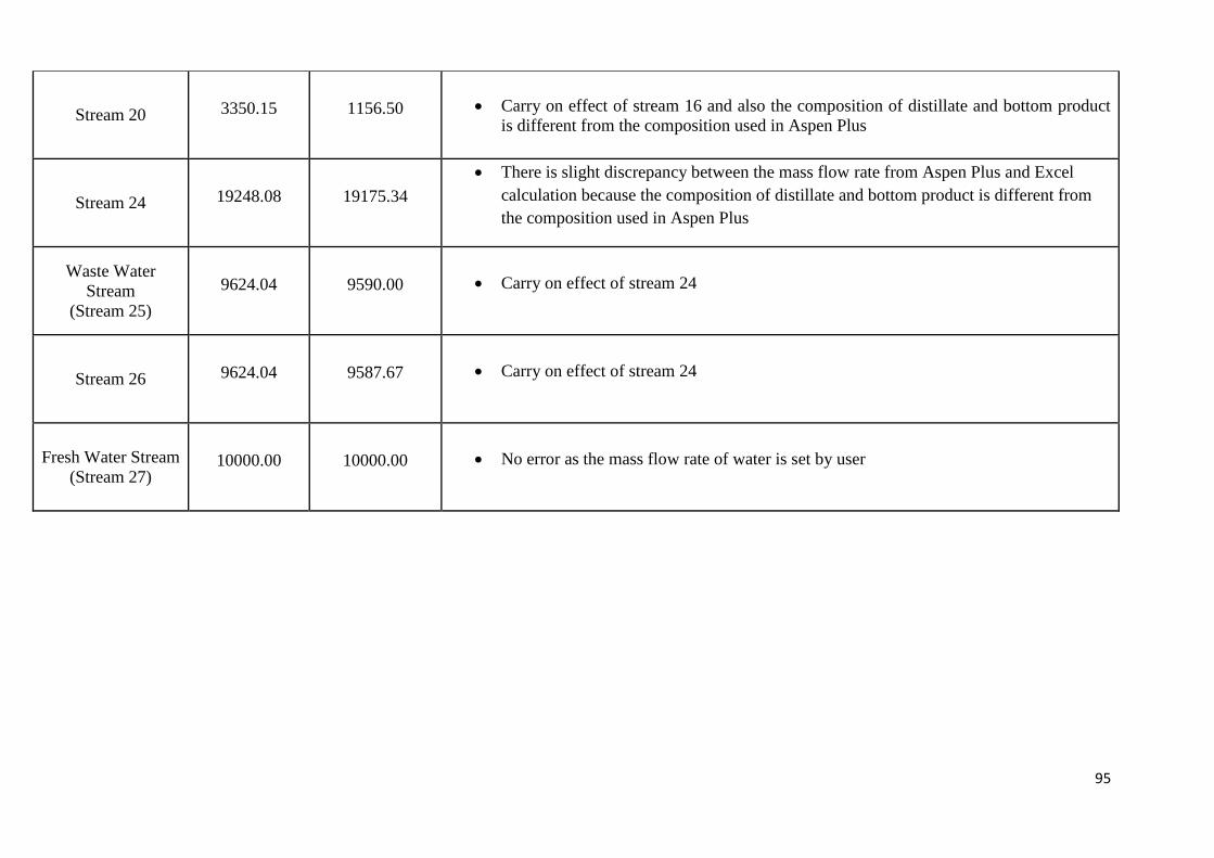
95
Stream 20 3350.15 1156.50 Carry on effect of stream 16 and also the composition of distillate and bottom product
is different from the composition used in Aspen Plus
Stream 24 19248.08 19175.34
There is slight discrepancy between the mass flow rate from Aspen Plus and Excel
calculation because the composition of distillate and bottom product is different from
the composition used in Aspen Plus
Waste Water
Stream
(Stream 25)
9624.04 9590.00 Carry on effect of stream 24
Stream 26 9624.04 9587.67 Carry on effect of stream 24
Fresh Water Stream
(Stream 27) 10000.00 10000.00 No error as the mass flow rate of water is set by user
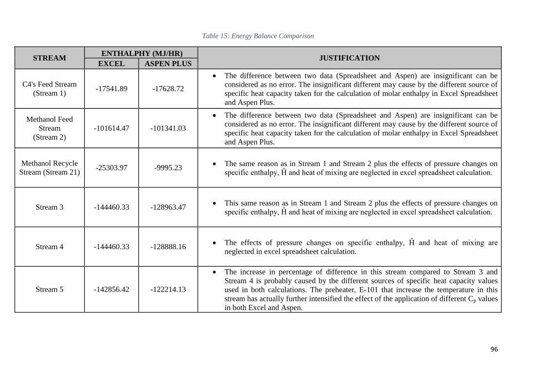
96
Table 15: Energy Balance Comparison
STREAM ENTHALPHY (MJ/HR)
JUSTIFICATION EXCEL ASPEN PLUS
C4's Feed Stream
(Stream 1) -17541.89 -17628.72
The difference between two data (Spreadsheet and Aspen) are insignificant can be
considered as no error. The insignificant different may cause by the different source of
specific heat capacity taken for the calculation of molar enthalpy in Excel Spreadsheet
and Aspen Plus.
Methanol Feed
Stream
(Stream 2)
-101614.47 -101341.03
The difference between two data (Spreadsheet and Aspen) are insignificant can be
considered as no error. The insignificant different may cause by the different source of
specific heat capacity taken for the calculation of molar enthalpy in Excel Spreadsheet
and Aspen Plus.
Methanol Recycle
Stream (Stream 21) -25303.97 -9995.23
The same reason as in Stream 1 and Stream 2 plus the effects of pressure changes on
specific enthalpy, Ĥ and heat of mixing are neglected in excel spreadsheet calculation.
Stream 3 -144460.33 -128963.47 This same reason as in Stream 1 and Stream 2 plus the effects of pressure changes on
specific enthalpy, Ĥ and heat of mixing are neglected in excel spreadsheet calculation.
Stream 4 -144460.33 -128888.16 The effects of pressure changes on specific enthalpy, Ĥ and heat of mixing are
neglected in excel spreadsheet calculation.
Stream 5 -142856.42 -122214.13
The increase in percentage of difference in this stream compared to Stream 3 and
Stream 4 is probably caused by the different sources of specific heat capacity values
used in both calculations. The preheater, E-101 that increase the temperature in this
stream has actually further intensified the effect of the application of different Cp values
in both Excel and Aspen.
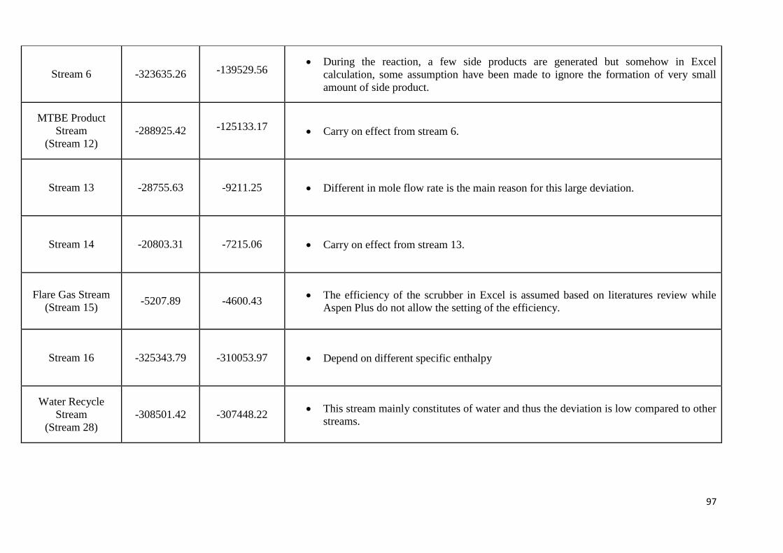
97
Stream 6 -323635.26 -139529.56 During the reaction, a few side products are generated but somehow in Excel
calculation, some assumption have been made to ignore the formation of very small
amount of side product.
MTBE Product
Stream
(Stream 12)
-288925.42 -125133.17 Carry on effect from stream 6.
Stream 13 -28755.63 -9211.25 Different in mole flow rate is the main reason for this large deviation.
Stream 14 -20803.31 -7215.06 Carry on effect from stream 13.
Flare Gas Stream
(Stream 15) -5207.89 -4600.43
The efficiency of the scrubber in Excel is assumed based on literatures review while
Aspen Plus do not allow the setting of the efficiency.
Stream 16 -325343.79 -310053.97 Depend on different specific enthalpy
Water Recycle
Stream
(Stream 28)
-308501.42 -307448.22 This stream mainly constitutes of water and thus the deviation is low compared to other
streams.
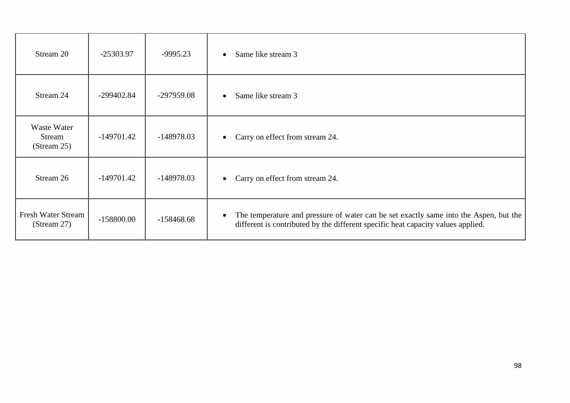
98
Stream 20 -25303.97 -9995.23 Same like stream 3
Stream 24 -299402.84 -297959.08 Same like stream 3
Waste Water
Stream
(Stream 25)
-149701.42 -148978.03 Carry on effect from stream 24.
Stream 26 -149701.42 -148978.03 Carry on effect from stream 24.
Fresh Water Stream
(Stream 27) -158800.00 -158468.68
The temperature and pressure of water can be set exactly same into the Aspen, but the
different is contributed by the different specific heat capacity values applied.
99
7.18.1 Mass Balance Justification between Manual Calculation and Aspen Simulation
In the manual (Excel Spreadsheet) calculation, ideal state assumption is made. While the
calculation based on Aspen Plus stimulation, UNIFAC is selected as the property method to
simulate the process [1]. Hence, some deviations are observed due to different basis of calculation
and phase determination.
As stated in previous section, this MTBE production plant with capacity of 300,000 tonnes
per annum is operating 24 hours and 350 days throughout a year. Hence, the mass flow rate of the
isobutylene setting is 26092.18 kg per hour. By looking the mass flow rate of isobutylene at
stream 1 for both excel hand calculation and aspen plus, the total mass flow rate is almost the
same, which are 26142.48 kg per hour. This is because the total mass flow rate of stream 1 is
depending on the capacity of production.
Mass flow rate of stream 2 is the mass flow rate of fresh feed methanol. The mass flow
rate of the methanol at stream 2 for bothe excel hand calculation and aspen plus is almost the
same, which is 13586.91 kg per hour. This is because the total mass flow rate of stream 2 is
depending on the capacity of production.
Mass flow rate of stream 3 is combination of mass flow rate of stream 1 and 2 together
with recycle stream 21. The total mass flow rate of stream 3 for excel hand calculation and aspen
plus are 43011.39 kg/hr and 40885.69/hr respectively. There are 2125.70kg/hr deviation. The
mass flow rate of methanol and also isobutylene have small deviation. Besides, the composition of
the distillate and bottom product of distillation column is different in excel hand calculation and
aspen plus. This is due to:
i) The molecular weight of component using in the excel is exact value, for example
molecular weight of methanol is 32kg/kmol, while the molecular weight using in aspen
have many decimal places. This cause the value deviate from the excel hand calculation.
ii) The recycled stream 21 is from the outlet of distillation column. In hand calculation,
assumption is made so that only light key and heavy key will distributed. For example,
water is heavy than heavy key, so that it wont distributed at the top product of distillation
column. Doing stage by stage equilibirum on hand calculation is very time consuming
and required huge times of try an errors. But on the other hand, aspen is using rigorous
method, it will run stage by stage equilibrim, so that the mass flow rate of each
component will have some deviation from our hand calculation.
100
Stream 4 and 5, which is the stream come out from pump and heater respectively, the total
mass flow rate of the stream for excel and aspen was mentioned above. Thus, the effect of stream
3 is carry on to stream 4 and 5.
Stream 6 which is the stream come out from reactor. The total mass flow rate of the
stream for excel and aspen plus is 43011.39 kg/hr and 40885.69 kg/hr respectively. We can notice
that the deviation is same as the previous stream. This is because the mass flow rate of the stream
is affected by stream 21 which is recycled methanol.
Stream 12 which is the MTBE product stream from T-101 (distillation column). The total
mass flow rate of the stream for excel and aspen plus is 37355.26 kg/hr and 37510.12 kg/hr
respectively. There is devation of the mass flowrate in excel calculation from aspen plus. Same as
stream 13 which is the distillate product from T-101. The total mass flow rate of the stream for
excel and aspen plus is 5656.13 kg/hr and 3375.57 kg/hr respectively. Same as stream 12, there is
deviation in excel calculation compared to aspen plus. This is due to the composition of distillate
and bottom product set by excel hand calculation is different from aspen plus. Following by
stream 14, the total mass flow rate of the stream for excel and aspen plus also different as it carry
on the effect from stream 13.
By looking at the total mass flow rate of stream 15 (flare gas stream), the total mass flow
rate of excel hand calculation is 2681.95 kg/hr whereas for aspen plus, we get 2631.47 kg/hr.
There is slight deviation due to the composition of MTBE escape through flare gas stream is
different for excel calculation and aspen plus. In excel hand calculation, we assume 10% of
MTBE will escape through the flare gas stream. However, in aspen plus, we found out that 97.6%
of MTBE will escape through the flare gas stream. This cause the difference in the total mass flow
rate of excel calculation and also the aspen plus. Same as stream 16, the total mass flow rate also
deviate due to the difference composition of MTBE used.
For stream 28, which is the stream of fresh feed water plus recycle stream of water, the
total mass flow rate of water in excel and also aspen are 19624.04 kg/hr and 19587.67 kg/hr. The
deviation is due to in excel calculation, we assume that 1% of water will evaporate and escape
through flare gas stream. While, in aspen plus, all water will dissolve with methanol and send to
the distillation column, T-103.
For stream 20, which is the distillate product stream come out from distillation column,T-
103. The total mass flow rate in excel and aspen are 3350.15 kg/hr and 1156.50 kg/hr
respectively. It show large deviation due to it carry on the effect of previous stream especialy
101
stream 13. This is because in stream 13, the composition of methanol in distillate product is
74.83% in aspen plus, whereas in excel calculation, we assume all methanol will distillated out as
top product. For stream 24, which is the bottom product stream come out from distillation column,
T-103. The total mass flow rate in excel and aspen are 19248.08 kg/hr and 19175.34 kg/hr
respectively. It show little discrepancy compared to distillate product stream. This is because in
stream 24, the composition of methanol is only 1%. Thus, it wont affect much.
For stream 25 and 26 which are the stream of recyled water and waste water stream
respectively. The reason of deviation is due to it carry on the effect of previous stream. On the
other hands, the total mass flow rate of stream 27 is same (10000 kg/hr). This is because stream
27 is fresh water feed. The value of mass flow rate is set by us in excel hand calculation as well as
aspen plus.
102
7.18.2 Energy Balance Justification between Manual Calculation and Aspen Simulation
For the energy balance, some of the streams are having huge differences when comparing
the manual calculation and the calculation generated by IT tools, Aspen Plus. The differences in
the calculation are basically due to the usage of different source of heat capacity coefficient. The
specific heat capacity for the excel manual calculation are mainly obtained either from Perry's
Chemical Engineers' Handbook or Elementary Principles of Chemical Processes. Meanwhile,
Aspen Plus calculated the enthalpy according to the database in Aspen Plus.
Also, another main contributor to the large deviation between Excel manual calculation
and Aspen simulate on is because of the application of different types of thermodynamic model.
In Aspen Plus simulation, UNIFAC method is chosen whereas in Excel manual calculation, the
ideal model is assumed. In addition, the calculation of energy or enthalpy in Aspen Plus software
is based on the hyperbolic function (from the Aspen Plus database) but for Excel manual
calculation, the polynomial function (mostly obtained from handbook) is used for the specific
enthalpy, Cp. Hence, the heat capacities applied in both manual Excel calculation and Aspen Plus
simulation are not same. Moreover, in the UNIFAC (Universal Functional Group Activity
Coefficient model) method, the activity coefficient, (splits into two components: a
combinatorial and a residual component ) of a component is considered in the equation
where for manual calculation, the following equation is used.
Since energy/enthalpy is the product if molar flow rate and specific enthalpy, so the
different in molar flow rate will also result in the deviation of energy. In other words, in the
energy balance, another major factor that affects the difference of enthalpy between Excel and
Aspen Plus is the carried on effect of the mass balance. The different mole flow rates will
eventually change the enthalpy in each stream. When mole flow rate deviate, the enthalpy must be
affected as well.
Generally, in the heat exchangers and pumps, the enthalpies do not show a large different
(below 1%); yet, for reactor and separation units especially distillation column, huge differences
between Excel’s calculation and Aspen’s simulation result are observed. This is due to in the
separation unit, the distribution of the components is different as mentioned above and also the
consideration of Gibbs energy of mixing, heat of absorption, heat of state changes and so on in
Aspen calculation. When the components distribution is different in both Excel and Aspen, then it
will definitely affect the mass balance and consequently the energy balance. In our case, a recycle
𝑄 + 𝑊 = ∆𝐻, where ∆𝐻 = ∫ 𝐶𝑃
𝑇
25
𝑑𝑇 + ∆𝐻𝑓25
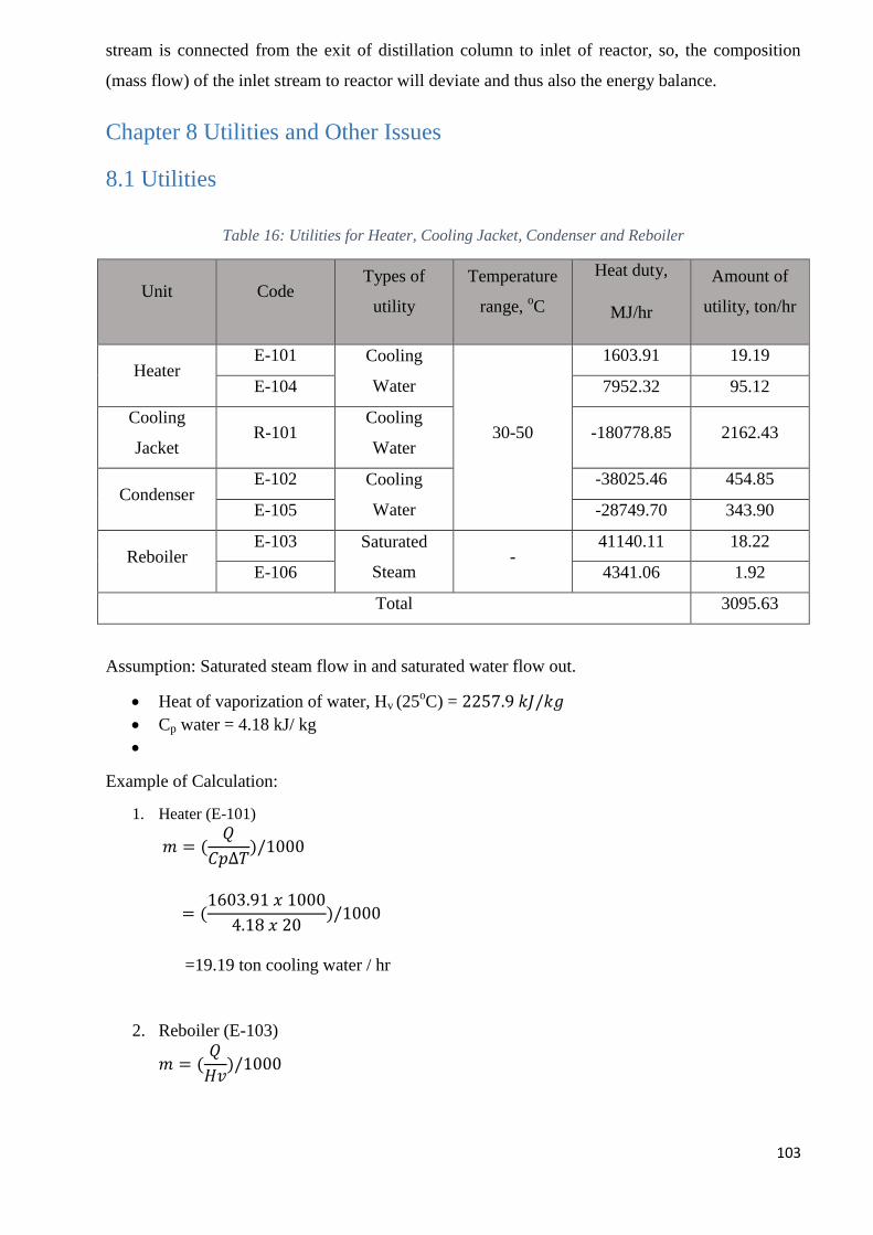
103
stream is connected from the exit of distillation column to inlet of reactor, so, the composition
(mass flow) of the inlet stream to reactor will deviate and thus also the energy balance.
Chapter 8 Utilities and Other Issues
8.1 Utilities
Table 16: Utilities for Heater, Cooling Jacket, Condenser and Reboiler
Unit Code Types of
utility
Temperature
range, oC
Heat duty,
MJ/hr
Amount of
utility, ton/hr
Heater E-101 Cooling
Water
30-50
1603.91 19.19
E-104 7952.32 95.12
Cooling
Jacket R-101
Cooling
Water -180778.85 2162.43
Condenser E-102 Cooling
Water
-38025.46 454.85
E-105 -28749.70 343.90
Reboiler E-103 Saturated
Steam -
41140.11 18.22
E-106 4341.06 1.92
Total 3095.63
Assumption: Saturated steam flow in and saturated water flow out.
Heat of vaporization of water, Hv (25oC) = 2257.9 𝑘𝐽/𝑘𝑔
Cp water = 4.18 kJ/ kg
Example of Calculation:
1. Heater (E-101)
𝑚 = (𝑄
𝐶𝑝∆𝑇)/1000
= (1603.91 𝑥 1000
4.18 𝑥 20)/1000
=19.19 ton cooling water / hr
2. Reboiler (E-103)
𝑚 = (𝑄
𝐻𝑣)/1000
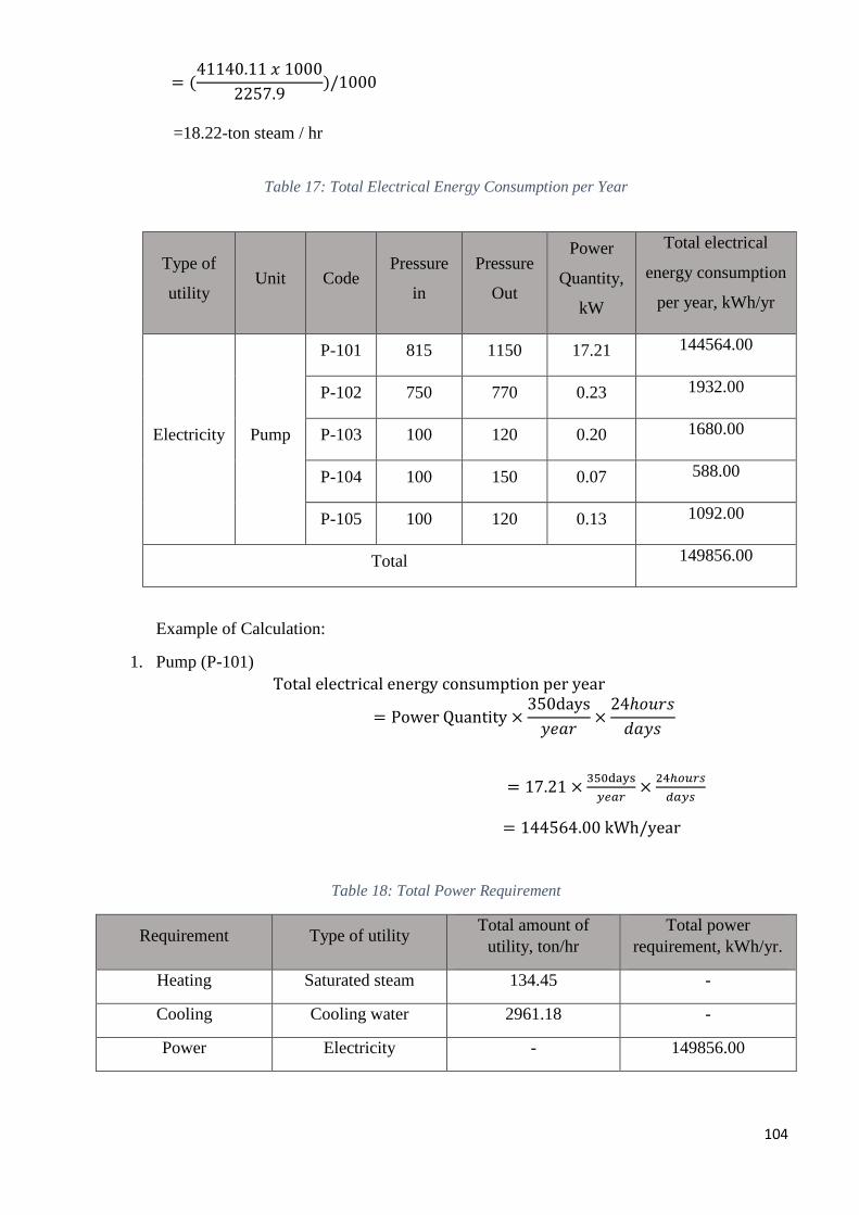
104
= (41140.11 𝑥 1000
2257.9)/1000
=18.22-ton steam / hr
Table 17: Total Electrical Energy Consumption per Year
Type of
utility Unit Code
Pressure
in
Pressure
Out
Power
Quantity,
kW
Total electrical
energy consumption
per year, kWh/yr
Electricity Pump
P-101 815 1150 17.21 144564.00
P-102 750 770 0.23 1932.00
P-103 100 120 0.20 1680.00
P-104 100 150 0.07 588.00
P-105 100 120 0.13 1092.00
Total 149856.00
Example of Calculation:
1. Pump (P-101)
Total electrical energy consumption per year
= Power Quantity ×350days
𝑦𝑒𝑎𝑟×
24ℎ𝑜𝑢𝑟𝑠
𝑑𝑎𝑦𝑠
= 17.21 ×350days
𝑦𝑒𝑎𝑟×
24ℎ𝑜𝑢𝑟𝑠
𝑑𝑎𝑦𝑠
= 144564.00 kWh/year
Table 18: Total Power Requirement
Requirement Type of utility Total amount of
utility, ton/hr
Total power
requirement, kWh/yr.
Heating Saturated steam 134.45 -
Cooling Cooling water 2961.18 -
Power Electricity - 149856.00
105
8.2 Amount of Waste Generated
8.2.1 Liquid Waste There is one stream produce liquid waste which is stream 25 from T-103 which is
methanol recovery tower. The waste stream produced from methanol recovery tower consists of
water and methanol. 50% of it is recycle back to the water scrubber by mixing it with fresh feed
water. The rest is disposed. The outlet stream liquid produced contains 0.15 wt% of methanol and
99.85 wt% of water. The liquid waste generate 9624.039 kg/hr. Amount of waste generated per
year can be calculated as below.
𝑎𝑚𝑜𝑢𝑛𝑡 𝑜𝑓 𝑤𝑎𝑠𝑡𝑒 𝑔𝑒𝑛𝑒𝑟𝑎𝑡𝑒𝑑 𝑝𝑒𝑟 𝑦𝑒𝑎𝑟 = 9624.039𝑘𝑔
ℎ𝑟 ×
1 𝑡𝑜𝑛
1000 𝑘𝑔 ×
24 ℎ𝑟
1 𝑑𝑎𝑦 ×
350 𝑑𝑎𝑦𝑠
1 𝑦𝑒𝑎𝑟
= 80841.93𝑡𝑜𝑛
𝑦𝑟
𝑚𝑒𝑡ℎ𝑎𝑛𝑜𝑙 𝑐𝑜𝑛𝑡𝑒𝑛𝑡 𝑖𝑛 𝑙𝑖𝑞𝑢𝑖𝑑 𝑤𝑎𝑠𝑡𝑒 = 80841.93 𝑡𝑜𝑛
𝑦𝑟 ×
0.15
100
= 121.26𝑡𝑜𝑛
𝑦𝑟
𝑤𝑎𝑡𝑒𝑟 𝑐𝑜𝑛𝑡𝑒𝑛𝑡 𝑖𝑛 𝑙𝑖𝑞𝑢𝑖𝑑 𝑤𝑎𝑠𝑡𝑒 = 80841.39𝑡𝑜𝑛
𝑦𝑟 ×
99.85
100
= 80720.67 𝑡𝑜𝑛
𝑦𝑟
Thus, the total liquid waste produced in the MTBE plant is 80841.93 ton/yr. and the
amount of methanol and water present in the liquid waste is 121.26 ton and 80720.67 ton
respectively.
8.2.2 Vapor waste
There is one stream produce vapor waste which is stream 16 from T-102 which is water
scrubber. The waste stream produced from methanol scrubber consists of C4 mixture, unreacted
isobutylene, trace amount of methanol and MTBE. Besides, 1% of water will evaporate in the
water scrubber and escape out from stream 15. The outlet stream vapor will send to burn as flare
gas. The waste produced is carbon dioxide, carbon monoxide and water. The vapor waste generate
2681.945 kg/hr. Amount of waste generated per year can be calculated as below.
𝑎𝑚𝑜𝑢𝑛𝑡 𝑜𝑓 𝑤𝑎𝑠𝑡𝑒𝑔𝑒𝑛𝑒𝑟𝑎𝑡𝑒𝑑 𝑝𝑒𝑟 𝑦𝑒𝑎𝑟 = 2681.945 𝑘𝑔
ℎ𝑟 ×
1 𝑡𝑜𝑛
1000 𝑘𝑔 ×
24 ℎ𝑟
1 𝑑𝑎𝑦 ×
350 𝑑𝑎𝑦𝑠
1 𝑦𝑒𝑎𝑟
106
= 22528.34 𝑡𝑜𝑛
𝑦𝑟
Thus, the total vapor waste produced in the MTBE plant is 22528.34 ton/yr.
8.2.3 Mode of liquid waste and vapour waste disposal
Methanol is a colorless, flammable liquid used in the manufacture of formaldehyde and
acetic acid. Methanol is released to the environment during industrial uses and naturally from
volcanic gases, vegetation and microbes. Exposure may occur from ambient air and during the use
of solvents. Acute (short term) or chronic (long term) exposure of humans to methanol by
inhalation or ingestion may result in blurred vision, headache, dizziness and nausea. Thus, the
liquid waste produced from the bottom of methanol recovery tower (distillation column, T-103)
need to be treated prior to discharge. Although the concentration of methanol in the effluent is low
which is only 0.15 wt%, it is still recommended to treat the effluent prior to discharge. The plant
will send the liquid waste to the wastewater treatment plant to remove the trace amount of
methanol. After methanol is being removed from the liquid mixture, then treated water can be
safely dispose to the environment.
Meanwhile, vapor waste is also produced in the MTBE production plant. The vapor waste
produced consists of carbon dioxide and water. At low carbon dioxide concentrations, our
breathing rate increases, capillaries dilate and the skin becomes flushed. With more severe
exposure, the rapid breathing becomes labored, causing restless, faintness, headache, and dulling
of consciousness. High concentration of carbon dioxide can cause asphyxiation quickly, without
warning, regardless of the oxygen concentration. Liquid carbon dioxide is so cold that skin
contact can result in severe frostbite, skin burns and other tissue damage. Thus, the vapor mixture
is first sent to treatment in order to separate carbon dioxide and water. The carbon dioxide cannot
directly dispose to the atmosphere, as it will cause the greenhouse effect. Carbon dioxide can be
sold to other industry such as food industry, electronic industry and etc. Carbon dioxide can be
converted into dry ice and is then used in the food industry for freezing food, for keeping food
cold during transport and for adding carbonation to beverages. On the other hands, in the
electronics industry, carbon dioxide is used in manufacturing applications, including
semiconductor device manufacturing, surface cleaning and circuit board assembly. Furthermore,
the chemical industry uses carbon dioxide to produce fertilizers, plastics and polymers. It is also
used to purge, pressurize and cool equipment. This is the most profitable way to manage the vapor
waste (CO2 and H2O) and at the same time, we will not contribute to the greenhouse effect.
107
Chapter 9
9.1 Mass transfer Equipment Design
9.1.1 Distillation Column, T-101 Design Criteria:
This distillation column is used to separate desired product, MTBE from mixture of unreacted methanol,
C4 mixture and by-product.
Design Parameters:
Component
Distribution
Column Sizing Plate Hydraulic
Design
Mechanical Design
Number of Stages Tray Spacing Active Area Design Pressure
Reflux Ratio Flooding Velocity Hole Area Design Temperature
Number of Actual
Stages
Net Area Tray Thickness Material of
Construction
Tray Efficiency Downcomer Area Hole Diameter Column Wall
Thickness
Location of Feed
Stage
Column Diameter Liquid Flow
Arrangement
Column Head Design
Column Height Column Pressure Drop Insulation
Weeping Checking Stress Analysis
Downcomer Liquid
Backup
Column Support
Residence Time Nozzle Size
Entrainment Checking
Number of Holes
Design Basic:
Feed stream into the distillation column T-101 consist of a mixture of unreacted methanol, C4 mixture and
by product, TBA and diisobutylene. The total mass flow rate of feed is 43011.388 kg/hr at 75 oC and
1000kPa. Distillate is carried out from the top of the column operating at 67 oC and 750kPa. On the other
hand, the bottom of column operate at 120 oC and 750kPa.
Design Method:
Fenske-Underwood-Gilliland method is used for component distribution calculation. The column sizing,
plate hydraulic design and mechanical design of the distillation column is based on Coulson and
Richardson’s Chemical Engineering Design and Ray Sinnott and Gavin Towler’s Chemical Engineering
Design.
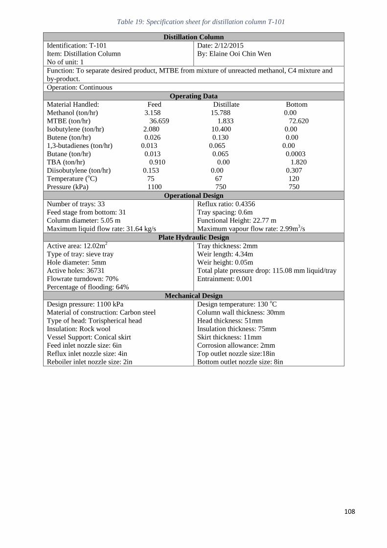
108
Table 19: Specification sheet for distillation column T-101
Distillation Column
Identification: T-101
Item: Distillation Column
No of unit: 1
Date: 2/12/2015
By: Elaine Ooi Chin Wen
Function: To separate desired product, MTBE from mixture of unreacted methanol, C4 mixture and
by-product.
Operation: Continuous
Operating Data
Material Handled: Feed Distillate Bottom
Methanol (ton/hr) 3.158 15.788 0.00
MTBE (ton/hr) 36.659 1.833 72.620
Isobutylene (ton/hr) 2.080 10.400 0.00
Butene (ton/hr) 0.026 0.130 0.00
1,3-butadienes (ton/hr) 0.013 0.065 0.00
Butane (ton/hr) 0.013 0.065 0.0003
TBA (ton/hr) 0.910 0.00 1.820
Diisobutylene (ton/hr) 0.153 0.00 0.307
Temperature (oC) 75 67 120
Pressure (kPa) 1100 750 750
Operational Design
Number of trays: 33
Feed stage from bottom: 31
Column diameter: 5.05 m
Maximum liquid flow rate: 31.64 kg/s
Reflux ratio: 0.4356
Tray spacing: 0.6m
Functional Height: 22.77 m
Maximum vapour flow rate: 2.99m3/s
Plate Hydraulic Design
Active area: 12.02m2
Type of tray: sieve tray
Hole diameter: 5mm
Active holes: 36731
Flowrate turndown: 70%
Percentage of flooding: 64%
Tray thickness: 2mm
Weir length: 4.34m
Weir height: 0.05m
Total plate pressure drop: 115.08 mm liquid/tray
Entrainment: 0.001
Mechanical Design
Design pressure: 1100 kPa
Material of construction: Carbon steel
Type of head: Torispherical head
Insulation: Rock wool
Vessel Support: Conical skirt
Feed inlet nozzle size: 6in
Reflux inlet nozzle size: 4in
Reboiler inlet nozzle size: 2in
Design temperature: 130 oC
Column wall thickness: 30mm
Head thickness: 51mm
Insulation thickness: 75mm
Skirt thickness: 11mm
Corrosion allowance: 2mm
Top outlet nozzle size:18in
Bottom outlet nozzle size: 8in
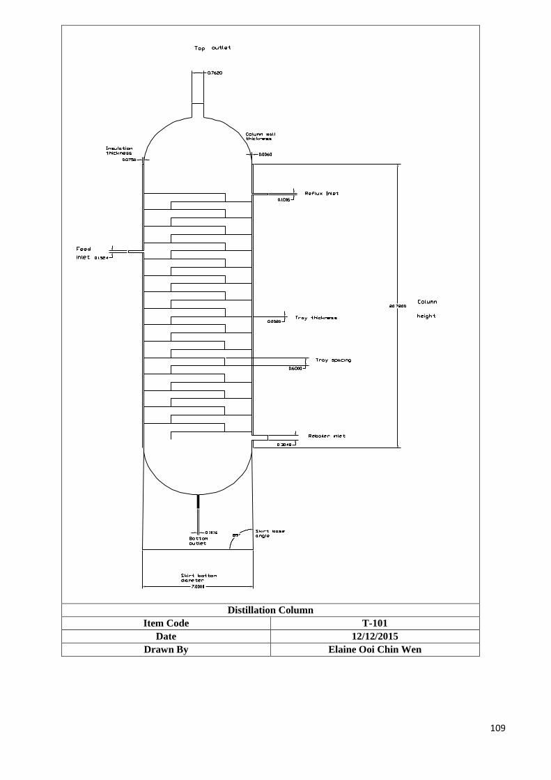
109
Distillation Column
Item Code T-101
Date 12/12/2015
Drawn By Elaine Ooi Chin Wen
110
9.1.2 METHANOL ABSORBER/SCRUBBER (T-102) Design Basic:
Feed stream that is channelled into the absorption tower (T-102) consists of a mixture of methanol,
isobutylene, MTBE, butene, 1,3-butadiene and also butane. The total mass flow rate of feed is
5656.13 kg/hr at 393.15K and 700 kPa. Water will acts as solvent and is sprayed from top of the
column while the feed stream in vapor state that contain methanol will flow from bottom of the
column and will contact with the downcoming water. Methanol will then be absorbed into the
water solvent. The exit gas will flow to stream 15, discharge into atmosphere from the top of the
column operating at 343.15K and 100kPa whereas the bottom of the column operating at 358.15K
and 100kPa will be remove as the exit liquid through stream 16. The solvent stream will enter this
column through stream 28 that carries out 27639.06 kg/hr component at 334.81K and 100kPa.
Design Parameter:
Absorber design Mechanical design
i) Number of stages
ii) Column diameter
iii) Overall height of transfer unit
iv) Height of packings
i) Design temperature
ii) Design pressure
iii) Material of construction
iv) Absorber head design
v) Wall thickness (vessel and head)
vi) Vessel support and base
vii) Nozzle size
Design Criteria:
Operating Temperature : 110 oC
Operating Pressure : 700 kPa
Vessel Orientation : Vertical
Type of Absorber : Random Packing Absorber
Type of Packing : Intalox Saddler Ceramic (1.5 inch)
Design Method:
Cornell et al. (1960) reviewed the previously published data and presented empirical equations for
predicting the height of the gas and liquid film transfer units. Their correlation takes into account
the physical properties of the system, the gas and liquid flow-rates; and the column diameter and
height. By referring the textbook (Coulson and Richardson's Chemical Engineering), the
calculations are performed and shown after the specification table.
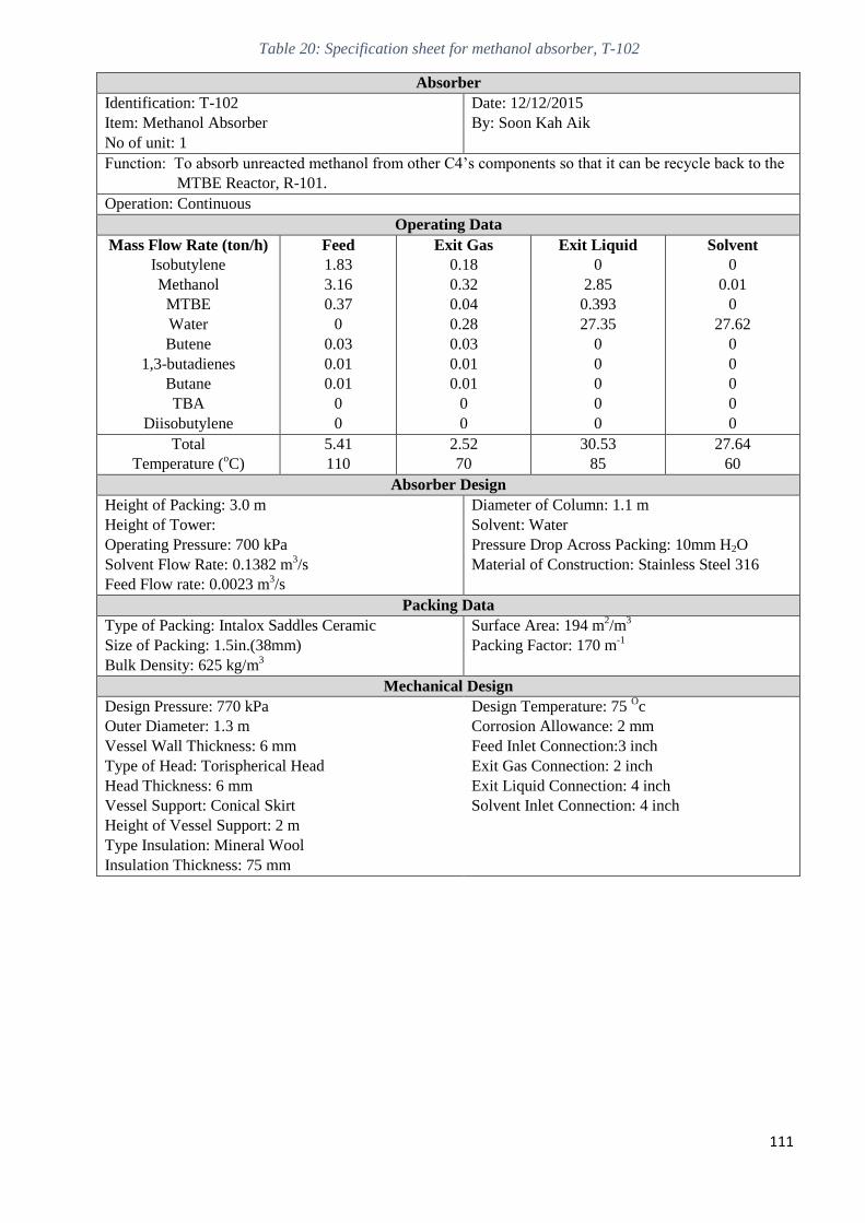
111
Table 20: Specification sheet for methanol absorber, T-102
Absorber
Identification: T-102
Item: Methanol Absorber
No of unit: 1
Date: 12/12/2015
By: Soon Kah Aik
Function: To absorb unreacted methanol from other C4’s components so that it can be recycle back to the
MTBE Reactor, R-101.
Operation: Continuous
Operating Data
Mass Flow Rate (ton/h)
Isobutylene
Methanol
MTBE
Water
Butene
1,3-butadienes
Butane
TBA
Diisobutylene
Feed
1.83
3.16
0.37
0
0.03
0.01
0.01
0
0
Exit Gas
0.18
0.32
0.04
0.28
0.03
0.01
0.01
0
0
Exit Liquid
0
2.85
0.393
27.35
0
0
0
0
0
Solvent
0
0.01
0
27.62
0
0
0
0
0
Total
Temperature (oC)
5.41
110
2.52
70
30.53
85
27.64
60
Absorber Design
Height of Packing: 3.0 m
Height of Tower:
Operating Pressure: 700 kPa
Solvent Flow Rate: 0.1382 m3/s
Feed Flow rate: 0.0023 m3/s
Diameter of Column: 1.1 m
Solvent: Water
Pressure Drop Across Packing: 10mm H2O
Material of Construction: Stainless Steel 316
Packing Data
Type of Packing: Intalox Saddles Ceramic
Size of Packing: 1.5in.(38mm)
Bulk Density: 625 kg/m3
Surface Area: 194 m2/m
3
Packing Factor: 170 m-1
Mechanical Design
Design Pressure: 770 kPa
Outer Diameter: 1.3 m
Vessel Wall Thickness: 6 mm
Type of Head: Torispherical Head
Head Thickness: 6 mm
Vessel Support: Conical Skirt
Height of Vessel Support: 2 m
Type Insulation: Mineral Wool
Insulation Thickness: 75 mm
Design Temperature: 75 Oc
Corrosion Allowance: 2 mm
Feed Inlet Connection:3 inch
Exit Gas Connection: 2 inch
Exit Liquid Connection: 4 inch
Solvent Inlet Connection: 4 inch
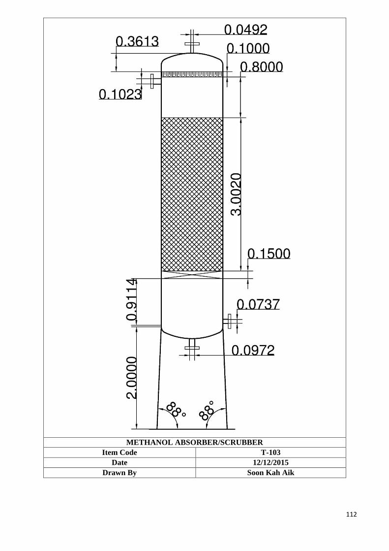
112
METHANOL ABSORBER/SCRUBBER
Item Code T-103
Date 12/12/2015
Drawn By Soon Kah Aik
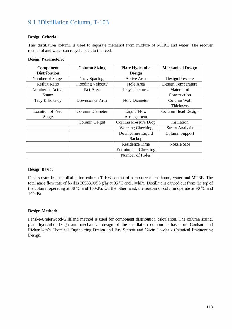
113
9.1.3Distillation Column, T-103
Design Criteria:
This distillation column is used to separate methanol from mixture of MTBE and water. The recover
methanol and water can recycle back to the feed.
Design Parameters:
Component
Distribution
Column Sizing Plate Hydraulic
Design
Mechanical Design
Number of Stages Tray Spacing Active Area Design Pressure
Reflux Ratio Flooding Velocity Hole Area Design Temperature
Number of Actual
Stages
Net Area Tray Thickness Material of
Construction
Tray Efficiency Downcomer Area Hole Diameter Column Wall
Thickness
Location of Feed
Stage
Column Diameter Liquid Flow
Arrangement
Column Head Design
Column Height Column Pressure Drop Insulation
Weeping Checking Stress Analysis
Downcomer Liquid
Backup
Column Support
Residence Time Nozzle Size
Entrainment Checking
Number of Holes
Design Basic:
Feed stream into the distillation column T-103 consist of a mixture of methanol, water and MTBE. The
total mass flow rate of feed is 30533.095 kg/hr at 85 oC and 100kPa. Distillate is carried out from the top of
the column operating at 38 oC and 100kPa. On the other hand, the bottom of column operate at 90
oC and
100kPa.
Design Method:
Fenske-Underwood-Gilliland method is used for component distribution calculation. The column sizing,
plate hydraulic design and mechanical design of the distillation column is based on Coulson and
Richardson’s Chemical Engineering Design and Ray Sinnott and Gavin Towler’s Chemical Engineering
Design.
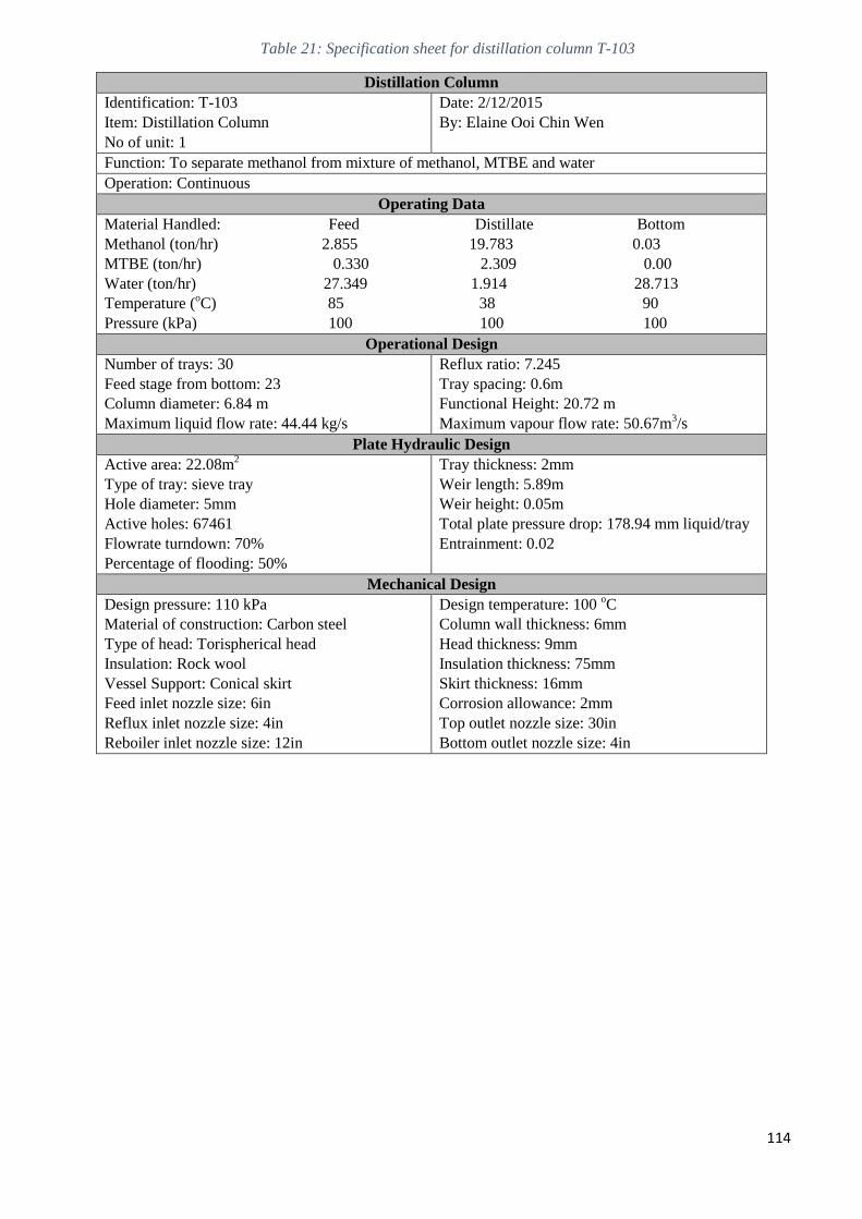
114
Table 21: Specification sheet for distillation column T-103
Distillation Column
Identification: T-103
Item: Distillation Column
No of unit: 1
Date: 2/12/2015
By: Elaine Ooi Chin Wen
Function: To separate methanol from mixture of methanol, MTBE and water
Operation: Continuous
Operating Data
Material Handled: Feed Distillate Bottom
Methanol (ton/hr) 2.855 19.783 0.03
MTBE (ton/hr) 0.330 2.309 0.00
Water (ton/hr) 27.349 1.914 28.713
Temperature (oC) 85 38 90
Pressure (kPa) 100 100 100
Operational Design
Number of trays: 30
Feed stage from bottom: 23
Column diameter: 6.84 m
Maximum liquid flow rate: 44.44 kg/s
Reflux ratio: 7.245
Tray spacing: 0.6m
Functional Height: 20.72 m
Maximum vapour flow rate: 50.67m3/s
Plate Hydraulic Design
Active area: 22.08m2
Type of tray: sieve tray
Hole diameter: 5mm
Active holes: 67461
Flowrate turndown: 70%
Percentage of flooding: 50%
Tray thickness: 2mm
Weir length: 5.89m
Weir height: 0.05m
Total plate pressure drop: 178.94 mm liquid/tray
Entrainment: 0.02
Mechanical Design
Design pressure: 110 kPa
Material of construction: Carbon steel
Type of head: Torispherical head
Insulation: Rock wool
Vessel Support: Conical skirt
Feed inlet nozzle size: 6in
Reflux inlet nozzle size: 4in
Reboiler inlet nozzle size: 12in
Design temperature: 100 oC
Column wall thickness: 6mm
Head thickness: 9mm
Insulation thickness: 75mm
Skirt thickness: 16mm
Corrosion allowance: 2mm
Top outlet nozzle size: 30in
Bottom outlet nozzle size: 4in
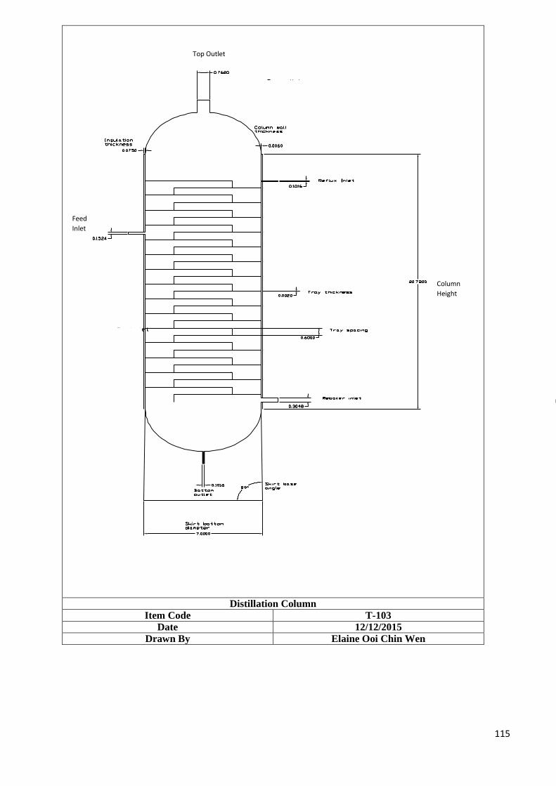
115
Distillation Column
Item Code T-103
Date 12/12/2015
Drawn By Elaine Ooi Chin Wen
Top Outlet
Column
Height
Feed
Inlet
116
9.2 Heat Transfer Equipment
9.2.1 Feed Heater, E-101 Design Criteria:
The feed heater E-101 is used to heat up the mixture of methanol, water, dimethyl ether, hydrogen,
nitrogen, carbon dioxide and carbon monoxide from storage tank and also recycle stream at 11.00
bar from T=90OC to T= 100
OC, before this stream enters the synthesis reactor (R-101). The steam
used to heat up the mixture enters at T=250OC and leaves at T=150
OC at 11.10 bar.
Design Parameter:
Outside diameter (OD) and inside diameter (ID) for tubes Number of tubes
Number of tube passes and shell passes
Diameter of tube bundle, DB
Diameter of shell, DS
Baffle spacing, lb
Overall heat transfer coefficient
Tube side pressure drop, ΔPt
Shell side pressure drop, ΔPs
Design Method:
The heat exchanger design is based on Coulson and Richardson’s Chemical Engineering Design. For the
properties of the components in stream, it is determined from Elementary Principles of Chemical Processes,
Handbook of Chemistry and Physics and Perry Chemical Engineer’s Handbook.
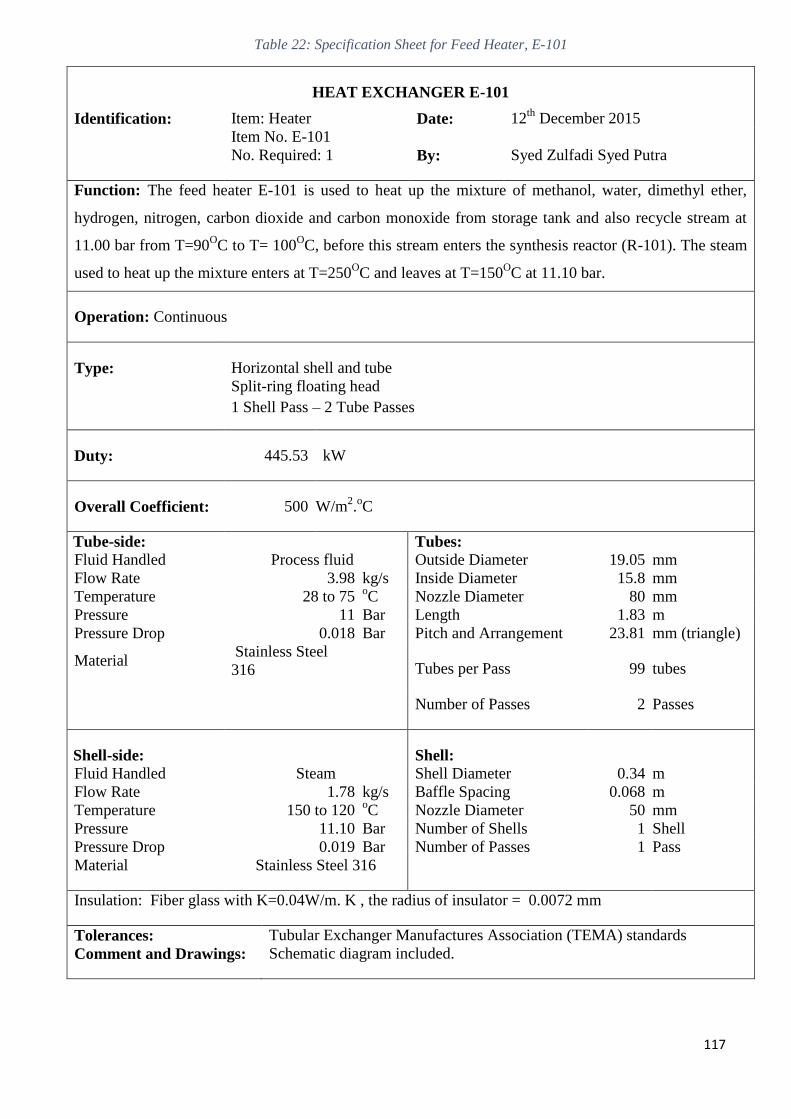
117
Table 22: Specification Sheet for Feed Heater, E-101
HEAT EXCHANGER E-101
Identification: Item: Heater Date: 12th
December 2015
Item No. E-101
No. Required: 1 By: Syed Zulfadi Syed Putra
Function: The feed heater E-101 is used to heat up the mixture of methanol, water, dimethyl ether,
hydrogen, nitrogen, carbon dioxide and carbon monoxide from storage tank and also recycle stream at
11.00 bar from T=90OC to T= 100
OC, before this stream enters the synthesis reactor (R-101). The steam
used to heat up the mixture enters at T=250OC and leaves at T=150
OC at 11.10 bar.
Operation: Continuous
Type: Horizontal shell and tube
Split-ring floating head
1 Shell Pass – 2 Tube Passes
Duty: 445.53 kW
Overall Coefficient: 500 W/m2.oC
Tube-side: Tubes:
Fluid Handled Process fluid Outside Diameter 19.05 mm
Flow Rate 3.98 kg/s Inside Diameter 15.8 mm
Temperature 28 to 75 oC Nozzle Diameter 80 mm
Pressure 11 Bar Length 1.83 m
Pressure Drop 0.018 Bar Pitch and Arrangement 23.81 mm (triangle)
Material Stainless Steel
316 Tubes per Pass 99 tubes
Number of Passes 2 Passes
Shell-side: Shell:
Fluid Handled Steam Shell Diameter 0.34 m
Flow Rate 1.78 kg/s Baffle Spacing 0.068 m
Temperature 150 to 120 oC Nozzle Diameter 50 mm
Pressure 11.10 Bar Number of Shells 1 Shell
Pressure Drop 0.019 Bar Number of Passes 1 Pass
Material Stainless Steel 316
Insulation: Fiber glass with K=0.04W/m. K , the radius of insulator = 0.0072 mm
Tolerances: Tubular Exchanger Manufactures Association (TEMA) standards
Comment and Drawings: Schematic diagram included.
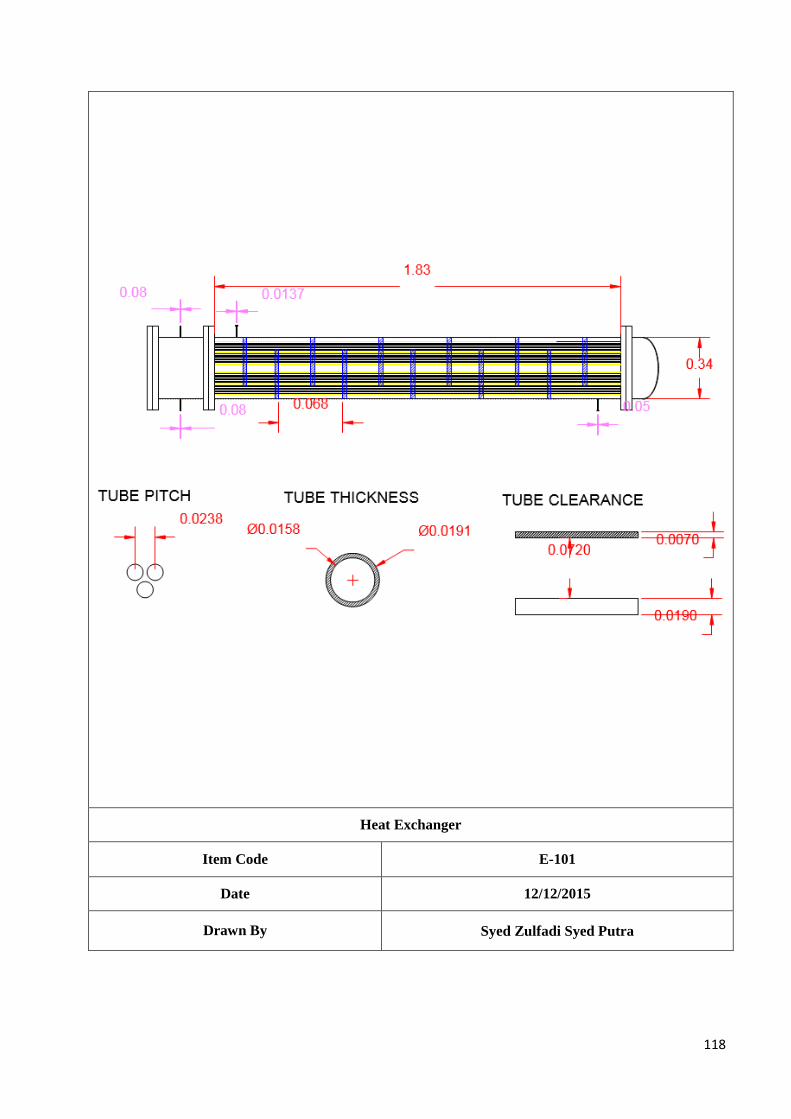
118
Heat Exchanger
Item Code E-101
Date 12/12/2015
Drawn By Syed Zulfadi Syed Putra
119
9.2.2 Condenser, E-102 Design Criteria:
The Condenser E-102 is used to condense the mixture of methanol, water, dimethyl ether,
hydrogen, nitrogen, carbon dioxide and carbon monoxide from synthesis reactor (R-101) at 7.50
bar from T=67OC to T= 62
OC, before this stream enters the distillation column (T-101). The brine
solution used to cool down the mixture enters at T=5OC and leaves at T=15
OC at 7.50 bar.
Design Parameter:
Outside diameter (OD) and inside diameter (ID) for tubes Number of tubes
Number of tube passes and shell passes
Diameter of tube bundle, DB
Diameter of shell, DS
Baffle spacing, lb
Overall heat transfer coefficient
Tube side pressure drop, ΔPt
Shell side pressure drop, ΔPs
Design Method:
The heat exchanger design is based on Coulson and Richardson’s Chemical Engineering Design. For the
properties of the components in stream, it is determined from Elementary Principles of Chemical Processes,
Handbook of Chemistry and Physics and Perry Chemical Engineer’s Handbook.
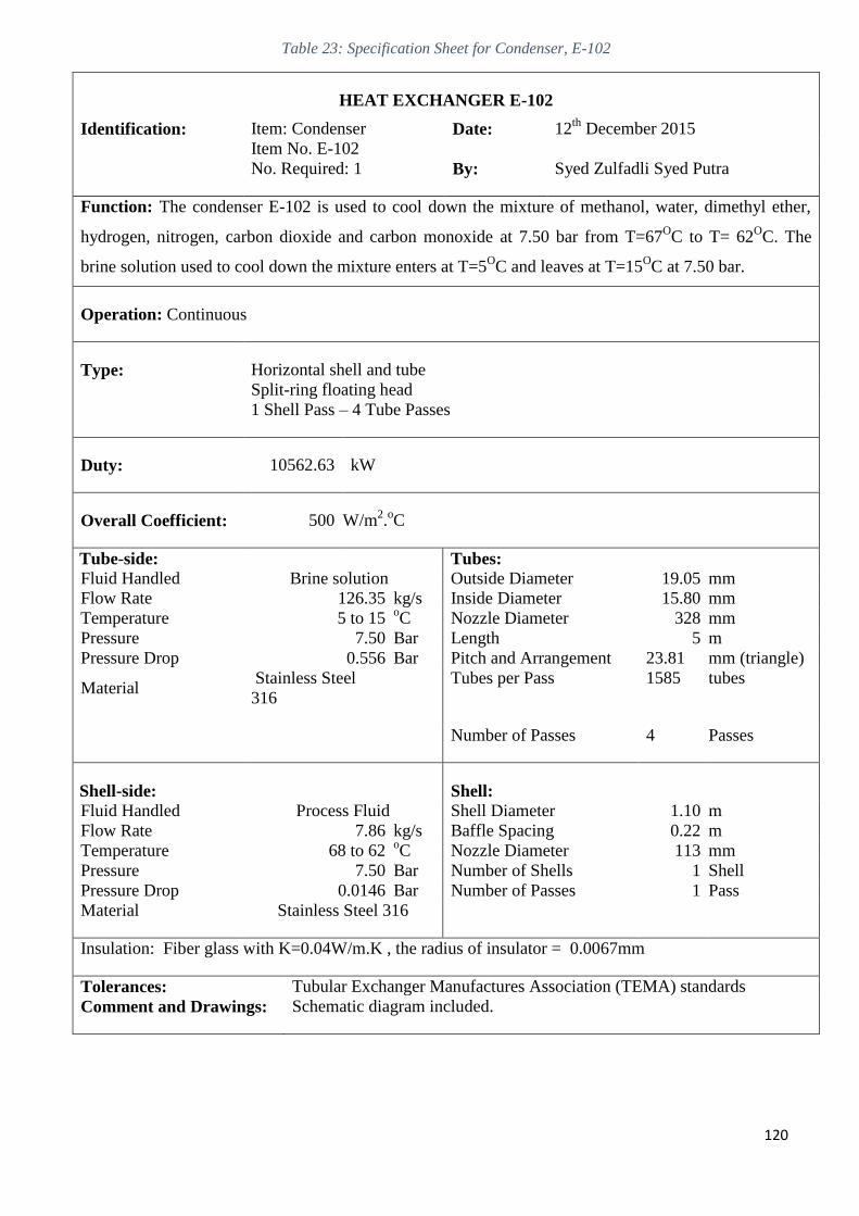
120
Table 23: Specification Sheet for Condenser, E-102
HEAT EXCHANGER E-102
Identification: Item: Condenser Date: 12th
December 2015
Item No. E-102
No. Required: 1 By: Syed Zulfadli Syed Putra
Function: The condenser E-102 is used to cool down the mixture of methanol, water, dimethyl ether,
hydrogen, nitrogen, carbon dioxide and carbon monoxide at 7.50 bar from T=67OC to T= 62
OC. The
brine solution used to cool down the mixture enters at T=5OC and leaves at T=15
OC at 7.50 bar.
Operation: Continuous
Type: Horizontal shell and tube
Split-ring floating head
1 Shell Pass – 4 Tube Passes
Duty: 10562.63 kW
Overall Coefficient: 500 W/m2.oC
Tube-side: Tubes:
Fluid Handled Brine solution Outside Diameter 19.05 mm
Flow Rate 126.35 kg/s Inside Diameter 15.80 mm
Temperature 5 to 15 oC Nozzle Diameter 328 mm
Pressure 7.50 Bar Length 5 m
Pressure Drop 0.556 Bar Pitch and Arrangement 23.81 mm (triangle)
Material Stainless Steel
316 Tubes per Pass 1585 tubes
Number of Passes 4 Passes
Shell-side: Shell:
Fluid Handled Process Fluid Shell Diameter 1.10 m
Flow Rate 7.86 kg/s Baffle Spacing 0.22 m
Temperature 68 to 62 oC Nozzle Diameter 113 mm
Pressure 7.50 Bar Number of Shells 1 Shell
Pressure Drop 0.0146 Bar Number of Passes 1 Pass
Material Stainless Steel 316
Insulation: Fiber glass with K=0.04W/m.K , the radius of insulator = 0.0067mm
Tolerances: Tubular Exchanger Manufactures Association (TEMA) standards
Comment and Drawings: Schematic diagram included.
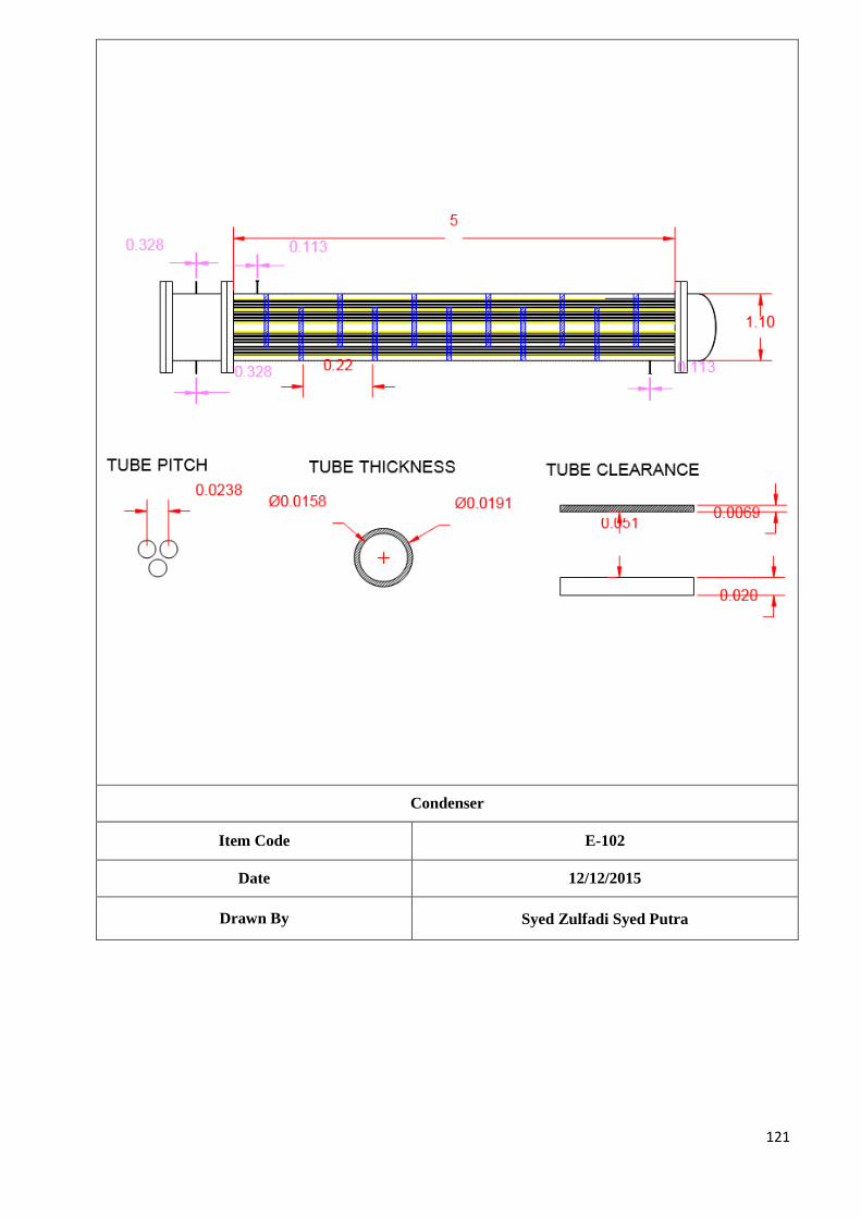
121
Condenser
Item Code E-102
Date 12/12/2015
Drawn By Syed Zulfadi Syed Putra
122
9.2.3 Reboiler, E-103 Design Criteria:
The reboiler E-103 is used to vaporise the mixture of methanol and water at 7.50 bar from T =
120OC to T = 130
OC. The steam used to vaporise the mixture enters at T=350
OC and leaves at
T=150OC at 7.50 bar.
Design Parameter:
Outside diameter (OD) and inside diameter (ID) for tubes Number of tubes
Number of tube passes and shell passes
Diameter of tube bundle, DB
Diameter of shell, DS
Baffle spacing, lb
Overall heat transfer coefficient
Tube side pressure drop, ΔPt
Shell side pressure drop, ΔPs
Design Method:
The heat exchanger design is based on Coulson and Richardson’s Chemical Engineering Design. For the
properties of the components in stream, it is determined from Elementary Principles of Chemical Processes,
Handbook of Chemistry and Physics and Perry Chemical Engineer’s Handbook.
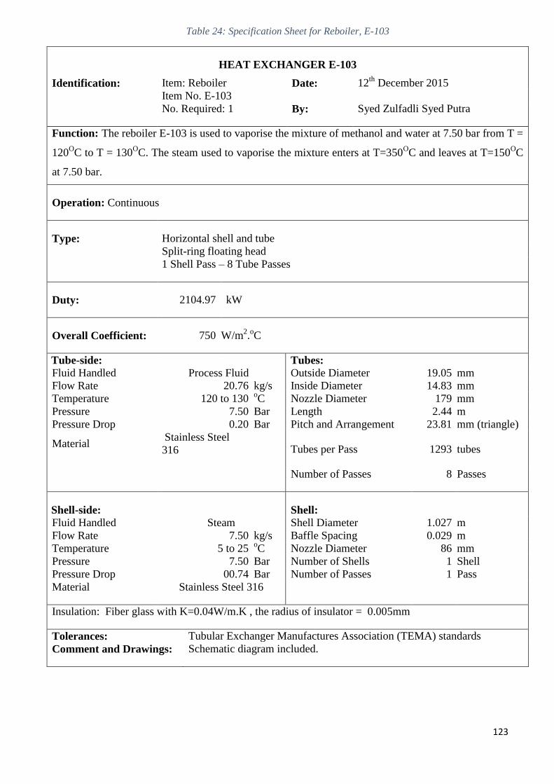
123
Table 24: Specification Sheet for Reboiler, E-103
HEAT EXCHANGER E-103
Identification: Item: Reboiler Date: 12th
December 2015
Item No. E-103
No. Required: 1 By: Syed Zulfadli Syed Putra
Function: The reboiler E-103 is used to vaporise the mixture of methanol and water at 7.50 bar from T =
120OC to T = 130
OC. The steam used to vaporise the mixture enters at T=350
OC and leaves at T=150
OC
at 7.50 bar.
Operation: Continuous
Type: Horizontal shell and tube
Split-ring floating head
1 Shell Pass – 8 Tube Passes
Duty: 2104.97 kW
Overall Coefficient: 750 W/m2.oC
Tube-side: Tubes:
Fluid Handled Process Fluid Outside Diameter 19.05 mm
Flow Rate 20.76 kg/s Inside Diameter 14.83 mm
Temperature 120 to 130 oC Nozzle Diameter 179 mm
Pressure 7.50 Bar Length 2.44 m
Pressure Drop 0.20 Bar Pitch and Arrangement 23.81 mm (triangle)
Material Stainless Steel
316 Tubes per Pass 1293 tubes
Number of Passes 8 Passes
Shell-side: Shell:
Fluid Handled Steam Shell Diameter 1.027 m
Flow Rate 7.50 kg/s Baffle Spacing 0.029 m
Temperature 5 to 25 oC Nozzle Diameter 86 mm
Pressure 7.50 Bar Number of Shells 1 Shell
Pressure Drop 00.74 Bar Number of Passes 1 Pass
Material Stainless Steel 316
Insulation: Fiber glass with K=0.04W/m.K , the radius of insulator = 0.005mm
Tolerances: Tubular Exchanger Manufactures Association (TEMA) standards
Comment and Drawings: Schematic diagram included.
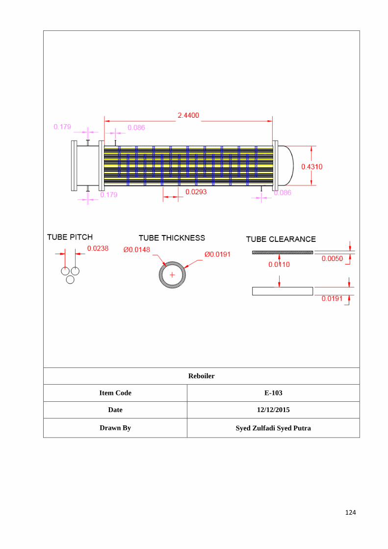
124
Reboiler
Item Code E-103
Date 12/12/2015
Drawn By Syed Zulfadi Syed Putra
125
9.2.4 Heater, E-104 Design Criteria:
The heater E-104 is used to heat up the process fluid from T= 62OC to T= 110
OC. The steam used
to heat the mixture enters at T=250OC and leaves at T=150
OC at 7 bar.
Design Parameter:
Outside diameter (OD) and inside diameter (ID) for tubes Number of tubes
Number of tube passes and shell passes
Diameter of tube bundle, DB
Diameter of shell, DS
Baffle spacing, lb
Overall heat transfer coefficient
Tube side pressure drop, ΔPt
Shell side pressure drop, ΔPs
Design Method:
The heat exchanger design is based on Coulson and Richardson’s Chemical Engineering Design. For the
properties of the components in stream, it is determined from Elementary Principles of Chemical Processes,
Handbook of Chemistry and Physics and Perry Chemical Engineer’s Handbook.
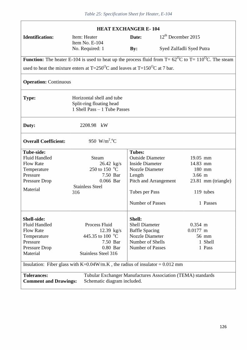
126
Table 25: Specification Sheet for Heater, E-104
HEAT EXCHANGER E- 104
Identification: Item: Heater Date: 12th
December 2015
Item No. E-104
No. Required: 1 By: Syed Zulfadli Syed Putra
Function: The heater E-104 is used to heat up the process fluid from T= 62OC to T= 110
OC. The steam
used to heat the mixture enters at T=250OC and leaves at T=150
OC at 7 bar.
Operation: Continuous
Type: Horizontal shell and tube
Split-ring floating head
1 Shell Pass – 1 Tube Passes
Duty: 2208.98 kW
Overall Coefficient: 950 W/m2.oC
Tube-side: Tubes:
Fluid Handled Steam Outside Diameter 19.05 mm
Flow Rate 26.42 kg/s Inside Diameter 14.83 mm
Temperature 250 to 150 oC Nozzle Diameter 180 mm
Pressure 7.50 Bar Length 3.66 m
Pressure Drop 0.066 Bar Pitch and Arrangement 23.81 mm (triangle)
Material Stainless Steel
316 Tubes per Pass 119 tubes
Number of Passes 1 Passes
Shell-side: Shell:
Fluid Handled Process Fluid Shell Diameter 0.354 m
Flow Rate 12.39 kg/s Baffle Spacing 0.0177 m
Temperature 445.35 to 100 oC Nozzle Diameter 56 mm
Pressure 7.50 Bar Number of Shells 1 Shell
Pressure Drop 0.80 Bar Number of Passes 1 Pass
Material Stainless Steel 316
Insulation: Fiber glass with K=0.04W/m.K , the radius of insulator = 0.012 mm
Tolerances: Tubular Exchanger Manufactures Association (TEMA) standards
Comment and Drawings: Schematic diagram included.
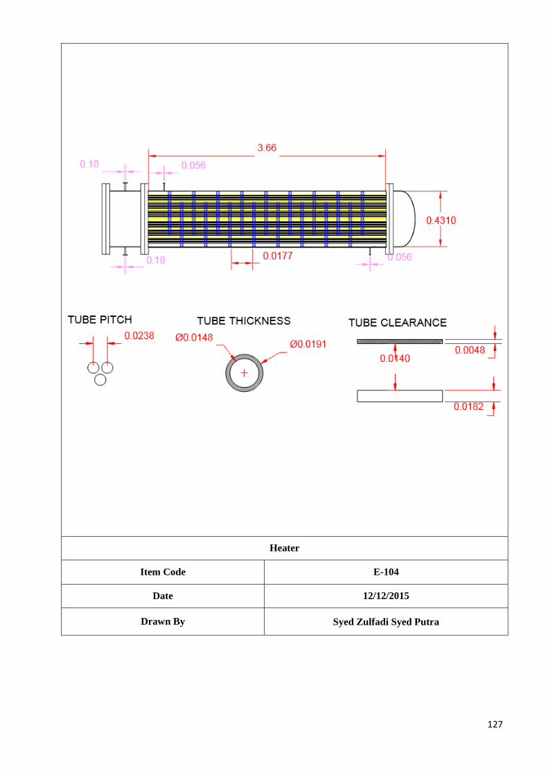
127
Heater
Item Code E-104
Date 12/12/2015
Drawn By Syed Zulfadi Syed Putra
128
9.2.5 Condenser, E-105 Design Criteria:
The condenser E-105 is used to condense the process mixture at 1 bar from T=38OC to T=
33OC.The brine solution used to condense the mixture enters at T=5
OC and leaves at T=15
OC at 1
bar.
Design Parameter:
Outside diameter (OD) and inside diameter (ID) for tubes Number of tubes
Number of tube passes and shell passes
Diameter of tube bundle, DB
Diameter of shell, DS
Baffle spacing, lb
Overall heat transfer coefficient
Tube side pressure drop, ΔPt
Shell side pressure drop, ΔPs
Design Method:
The heat exchanger design is based on Coulson and Richardson’s Chemical Engineering Design. For the
properties of the components in stream, it is determined from Elementary Principles of Chemical Processes,
Handbook of Chemistry and Physics and Perry Chemical Engineer’s Handbook.
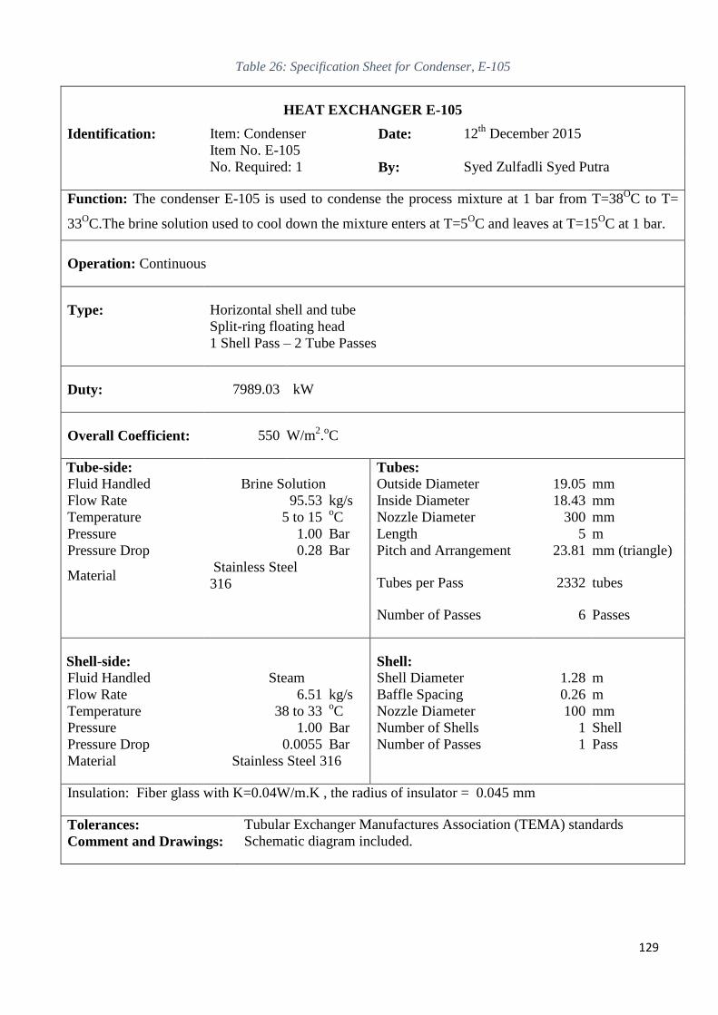
129
Table 26: Specification Sheet for Condenser, E-105
HEAT EXCHANGER E-105
Identification: Item: Condenser Date: 12th
December 2015
Item No. E-105
No. Required: 1 By: Syed Zulfadli Syed Putra
Function: The condenser E-105 is used to condense the process mixture at 1 bar from T=38OC to T=
33OC.The brine solution used to cool down the mixture enters at T=5
OC and leaves at T=15
OC at 1 bar.
Operation: Continuous
Type: Horizontal shell and tube
Split-ring floating head
1 Shell Pass – 2 Tube Passes
Duty: 7989.03 kW
Overall Coefficient: 550 W/m2.oC
Tube-side: Tubes:
Fluid Handled Brine Solution Outside Diameter 19.05 mm
Flow Rate 95.53 kg/s Inside Diameter 18.43 mm
Temperature 5 to 15 oC Nozzle Diameter 300 mm
Pressure 1.00 Bar Length 5 m
Pressure Drop 0.28 Bar Pitch and Arrangement 23.81 mm (triangle)
Material Stainless Steel
316 Tubes per Pass 2332 tubes
Number of Passes 6 Passes
Shell-side: Shell:
Fluid Handled Steam Shell Diameter 1.28 m
Flow Rate 6.51 kg/s Baffle Spacing 0.26 m
Temperature 38 to 33 oC Nozzle Diameter 100 mm
Pressure 1.00 Bar Number of Shells 1 Shell
Pressure Drop 0.0055 Bar Number of Passes 1 Pass
Material Stainless Steel 316
Insulation: Fiber glass with K=0.04W/m.K , the radius of insulator = 0.045 mm
Tolerances: Tubular Exchanger Manufactures Association (TEMA) standards
Comment and Drawings: Schematic diagram included.
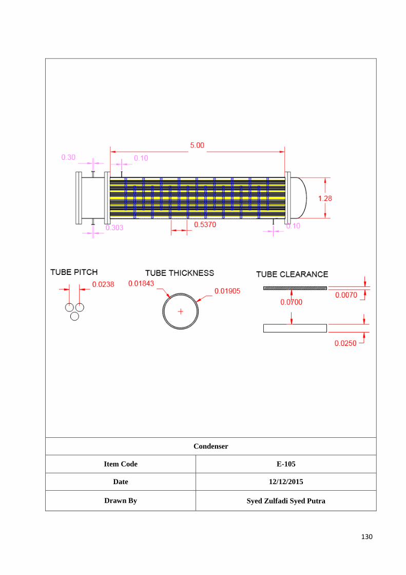
130
Condenser
Item Code E-105
Date 12/12/2015
Drawn By Syed Zulfadi Syed Putra
131
9.2.6 Reboiler, E-106
Design Criteria:
The Reboiler E-106 is used to vaporise the process mixture at 25 bar from T=90OC to T= 100
OC.
The steam used to heat up the mixture enters at T=250OC and leaves at T=150
OC at 26 bar.
Design Parameter:
Outside diameter (OD) and inside diameter (ID) for tubes Number of tubes
Number of tube passes and shell passes
Diameter of tube bundle, DB
Diameter of shell, DS
Baffle spacing, lb
Overall heat transfer coefficient
Tube side pressure drop, ΔPt
Shell side pressure drop, ΔPs
Design Method:
The heat exchanger design is based on Coulson and Richardson’s Chemical Engineering Design. For the
properties of the components in stream, it is determined from Elementary Principles of Chemical Processes,
Handbook of Chemistry and Physics and Perry Chemical Engineer’s Handbook.
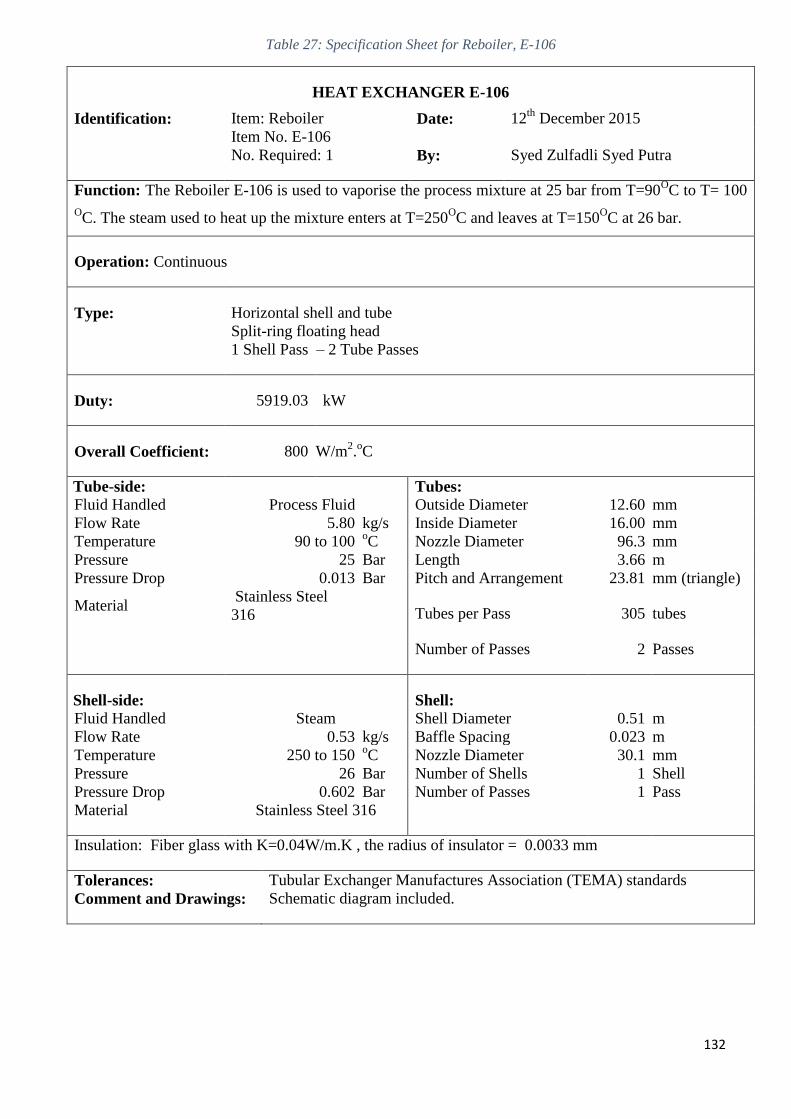
132
Table 27: Specification Sheet for Reboiler, E-106
HEAT EXCHANGER E-106
Identification: Item: Reboiler Date: 12th
December 2015
Item No. E-106
No. Required: 1 By: Syed Zulfadli Syed Putra
Function: The Reboiler E-106 is used to vaporise the process mixture at 25 bar from T=90OC to T= 100
OC. The steam used to heat up the mixture enters at T=250
OC and leaves at T=150
OC at 26 bar.
Operation: Continuous
Type: Horizontal shell and tube
Split-ring floating head
1 Shell Pass – 2 Tube Passes
Duty: 5919.03 kW
Overall Coefficient: 800 W/m2.oC
Tube-side: Tubes:
Fluid Handled Process Fluid Outside Diameter 12.60 mm
Flow Rate 5.80 kg/s Inside Diameter 16.00 mm
Temperature 90 to 100 oC Nozzle Diameter 96.3 mm
Pressure 25 Bar Length 3.66 m
Pressure Drop 0.013 Bar Pitch and Arrangement 23.81 mm (triangle)
Material Stainless Steel
316 Tubes per Pass 305 tubes
Number of Passes 2 Passes
Shell-side: Shell:
Fluid Handled Steam Shell Diameter 0.51 m
Flow Rate 0.53 kg/s Baffle Spacing 0.023 m
Temperature 250 to 150 oC Nozzle Diameter 30.1 mm
Pressure 26 Bar Number of Shells 1 Shell
Pressure Drop 0.602 Bar Number of Passes 1 Pass
Material Stainless Steel 316
Insulation: Fiber glass with K=0.04W/m.K , the radius of insulator = 0.0033 mm
Tolerances: Tubular Exchanger Manufactures Association (TEMA) standards
Comment and Drawings: Schematic diagram included.
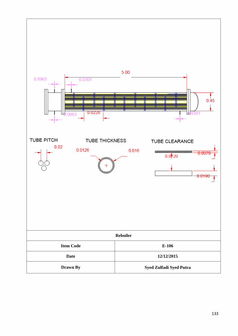
133
Reboiler
Item Code E-106
Date 12/12/2015
Drawn By Syed Zulfadi Syed Putra
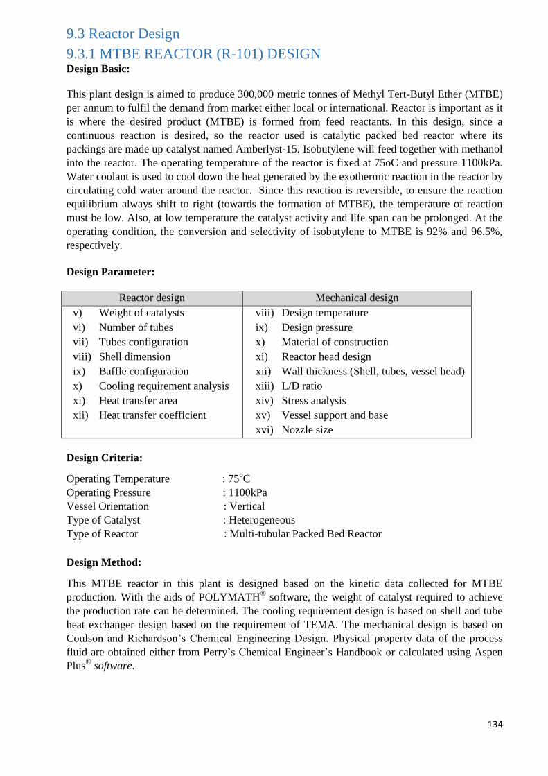
134
9.3 Reactor Design
9.3.1 MTBE REACTOR (R-101) DESIGN Design Basic:
This plant design is aimed to produce 300,000 metric tonnes of Methyl Tert-Butyl Ether (MTBE)
per annum to fulfil the demand from market either local or international. Reactor is important as it
is where the desired product (MTBE) is formed from feed reactants. In this design, since a
continuous reaction is desired, so the reactor used is catalytic packed bed reactor where its
packings are made up catalyst named Amberlyst-15. Isobutylene will feed together with methanol
into the reactor. The operating temperature of the reactor is fixed at 75oC and pressure 1100kPa.
Water coolant is used to cool down the heat generated by the exothermic reaction in the reactor by
circulating cold water around the reactor. Since this reaction is reversible, to ensure the reaction
equilibrium always shift to right (towards the formation of MTBE), the temperature of reaction
must be low. Also, at low temperature the catalyst activity and life span can be prolonged. At the
operating condition, the conversion and selectivity of isobutylene to MTBE is 92% and 96.5%,
respectively.
Design Parameter:
Reactor design Mechanical design
v) Weight of catalysts
vi) Number of tubes
vii) Tubes configuration
viii) Shell dimension
ix) Baffle configuration
x) Cooling requirement analysis
xi) Heat transfer area
xii) Heat transfer coefficient
viii) Design temperature
ix) Design pressure
x) Material of construction
xi) Reactor head design
xii) Wall thickness (Shell, tubes, vessel head)
xiii) L/D ratio
xiv) Stress analysis
xv) Vessel support and base
xvi) Nozzle size
Design Criteria:
Operating Temperature : 75oC
Operating Pressure : 1100kPa
Vessel Orientation : Vertical
Type of Catalyst : Heterogeneous
Type of Reactor : Multi-tubular Packed Bed Reactor
Design Method:
This MTBE reactor in this plant is designed based on the kinetic data collected for MTBE
production. With the aids of POLYMATH®
software, the weight of catalyst required to achieve
the production rate can be determined. The cooling requirement design is based on shell and tube
heat exchanger design based on the requirement of TEMA. The mechanical design is based on
Coulson and Richardson’s Chemical Engineering Design. Physical property data of the process
fluid are obtained either from Perry’s Chemical Engineer’s Handbook or calculated using Aspen
Plus®
software.
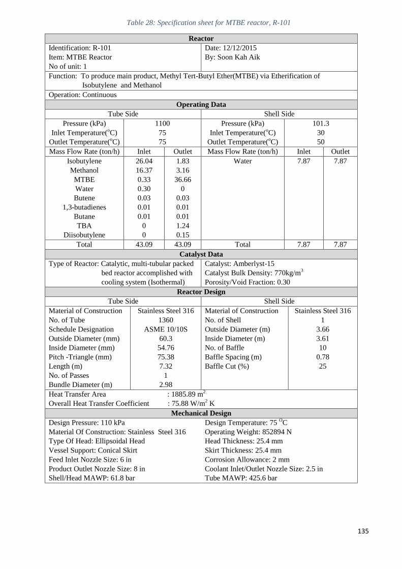
135
Table 28: Specification sheet for MTBE reactor, R-101
Reactor
Identification: R-101
Item: MTBE Reactor
No of unit: 1
Date: 12/12/2015
By: Soon Kah Aik
Function: To produce main product, Methyl Tert-Butyl Ether(MTBE) via Etherification of
Isobutylene and Methanol
Operation: Continuous
Operating Data
Tube Side Shell Side
Pressure (kPa)
Inlet Temperature(oC)
Outlet Temperature(oC)
1100
75
75
Pressure (kPa)
Inlet Temperature(oC)
Outlet Temperature(oC)
101.3
30
50
Mass Flow Rate (ton/h) Inlet Outlet Mass Flow Rate (ton/h) Inlet Outlet
Isobutylene
Methanol
MTBE
Water
Butene
1,3-butadienes
Butane
TBA
Diisobutylene
26.04
16.37
0.33
0.30
0.03
0.01
0.01
0
0
1.83
3.16
36.66
0
0.03
0.01
0.01
1.24
0.15
Water 7.87 7.87
Total 43.09 43.09 Total 7.87 7.87
Catalyst Data
Type of Reactor: Catalytic, multi-tubular packed
bed reactor accomplished with
cooling system (Isothermal)
Catalyst: Amberlyst-15
Catalyst Bulk Density: 770kg/m3
Porosity/Void Fraction: 0.30
Reactor Design
Tube Side Shell Side
Material of Construction
No. of Tube
Schedule Designation
Outside Diameter (mm)
Inside Diameter (mm)
Pitch -Triangle (mm)
Length (m)
No. of Passes
Bundle Diameter (m)
Stainless Steel 316
1360
ASME 10/10S
60.3
54.76
75.38
7.32
1
2.98
Material of Construction
No. of Shell
Outside Diameter (m)
Inside Diameter (m)
No. of Baffle
Baffle Spacing (m)
Baffle Cut (%)
Stainless Steel 316
1
3.66
3.61
10
0.78
25
Heat Transfer Area : 1885.89 m2
Overall Heat Transfer Coefficient : 75.88 W/m2 K
Mechanical Design
Design Pressure: 110 kPa
Material Of Construction: Stainless Steel 316
Type Of Head: Ellipsoidal Head
Vessel Support: Conical Skirt
Feed Inlet Nozzle Size: 6 in
Product Outlet Nozzle Size: 8 in
Shell/Head MAWP: 61.8 bar
Design Temperature: 75 OC
Operating Weight: 852894 N
Head Thickness: 25.4 mm
Skirt Thickness: 25.4 mm
Corrosion Allowance: 2 mm
Coolant Inlet/Outlet Nozzle Size: 2.5 in
Tube MAWP: 425.6 bar
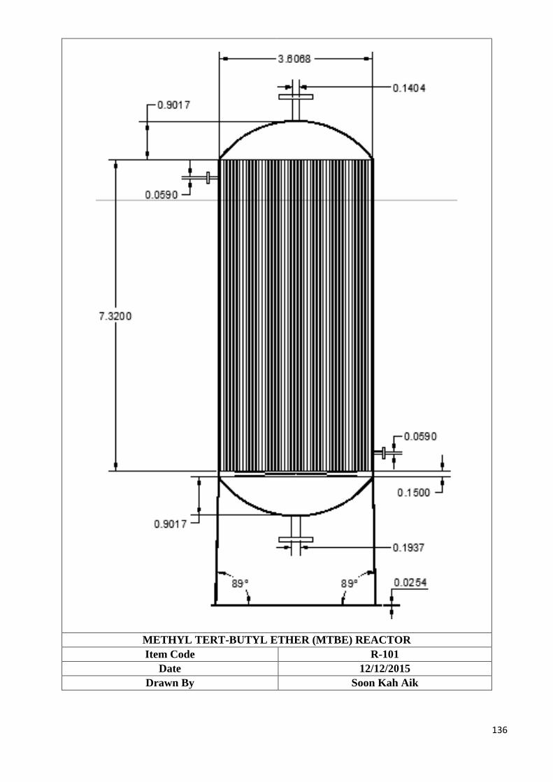
136
METHYL TERT-BUTYL ETHER (MTBE) REACTOR
Item Code R-101
Date 12/12/2015
Drawn By Soon Kah Aik
137
9.4 Auxiliary Equipment Design
9.4.1 Pump Design Criteria:
The purpose of pump is to pump and transport liquid to the next unit by mechanical means. There are total
5 pumps involved which are P-101, P-102, P-103, P-104 and P-105.
The functions of each different pump are stated as below:
P-101: To pump the mixture of fresh feed (isobutylene and methanol) and recycled methanol to the feed
heater (E-101)
P-102: To pump the distillate product back to the distillation column (T-101) via reflux inlet
P-103: To pump the distillate product back to the distillation column (T-103) via reflux inlet
P-104: To pump the recovery methanol from distillation column (T-103) back to the fresh methanol feed
stream.
P-105: To pump the recovery water from the distillation column (T-103) back to fresh water feed stream.
Design Parameters:
Pump
Nozzle Size
Total Head
NPSH
Motor Power
Design Method:
The pump power design is based on the Bernoulli’s Equation which is:
𝑃1
𝜌𝑔+ 𝑧1 +
𝑣12
2𝑔+ ℎ𝑝 =
𝑃2
𝜌𝑔+ 𝑧2 +
𝑣22
2𝑔+ ℎ𝑓
The overall pump design is based on the pump supplier’s pump performance curve.
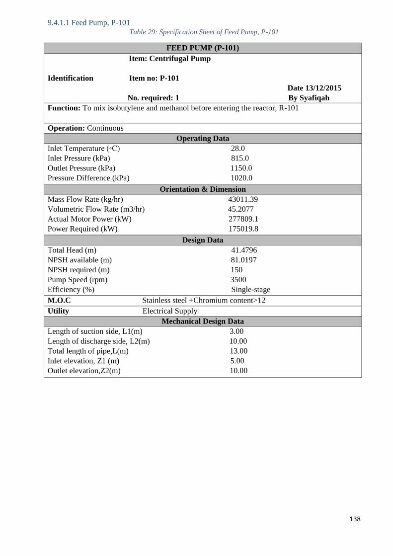
138
9.4.1.1 Feed Pump, P-101
Table 29: Specification Sheet of Feed Pump, P-101
FEED PUMP (P-101)
Item: Centrifugal Pump
Identification Item no: P-101
Date 13/12/2015
No. required: 1 By Syafiqah
Function: To mix isobutylene and methanol before entering the reactor, R-101
Operation: Continuous
Operating Data
Inlet Temperature (◦C) 28.0
Inlet Pressure (kPa) 815.0
Outlet Pressure (kPa) 1150.0
Pressure Difference (kPa) 1020.0
Orientation & Dimension
Mass Flow Rate (kg/hr) 43011.39
Volumetric Flow Rate (m3/hr) 45.2077
Actual Motor Power (kW) 277809.1
Power Required (kW) 175019.8
Design Data
Total Head (m) 41.4796
NPSH available (m) 81.0197
NPSH required (m) 150
Pump Speed (rpm) 3500
Efficiency (%) Single-stage
M.O.C Stainless steel +Chromium content>12
Utility Electrical Supply
Mechanical Design Data
Length of suction side, L1(m) 3.00
Length of discharge side, L2(m) 10.00
Total length of pipe,L(m) 13.00
Inlet elevation, Z1 (m) 5.00
Outlet elevation,Z2(m) 10.00
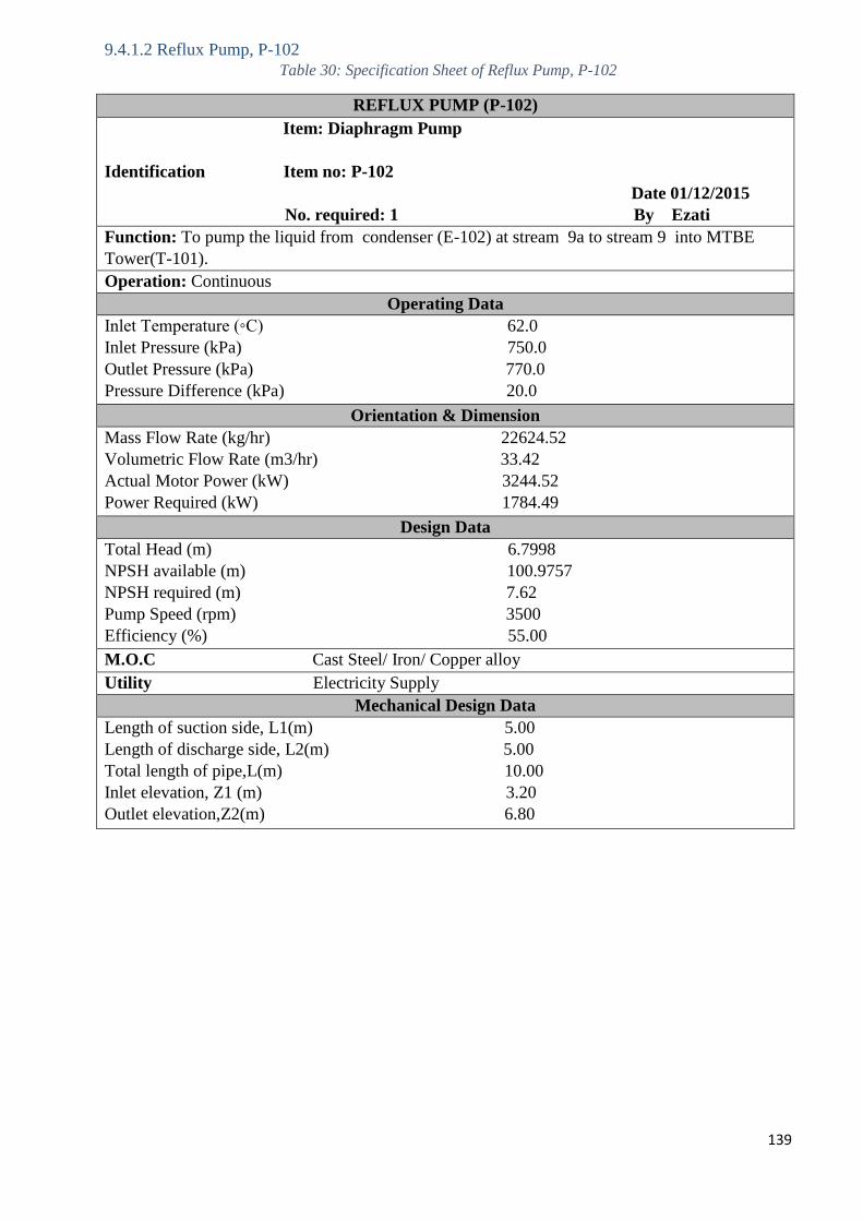
139
9.4.1.2 Reflux Pump, P-102
Table 30: Specification Sheet of Reflux Pump, P-102
REFLUX PUMP (P-102)
Item: Diaphragm Pump
Identification Item no: P-102
Date 01/12/2015
No. required: 1 By Ezati
Function: To pump the liquid from condenser (E-102) at stream 9a to stream 9 into MTBE
Tower(T-101).
Operation: Continuous
Operating Data
Inlet Temperature (◦C) 62.0
Inlet Pressure (kPa) 750.0
Outlet Pressure (kPa) 770.0
Pressure Difference (kPa) 20.0
Orientation & Dimension
Mass Flow Rate (kg/hr) 22624.52
Volumetric Flow Rate (m3/hr) 33.42
Actual Motor Power (kW) 3244.52
Power Required (kW) 1784.49
Design Data
Total Head (m) 6.7998
NPSH available (m) 100.9757
NPSH required (m) 7.62
Pump Speed (rpm) 3500
Efficiency (%) 55.00
M.O.C Cast Steel/ Iron/ Copper alloy
Utility Electricity Supply
Mechanical Design Data
Length of suction side, L1(m) 5.00
Length of discharge side, L2(m) 5.00
Total length of pipe,L(m) 10.00
Inlet elevation, Z1 (m) 3.20
Outlet elevation,Z2(m) 6.80
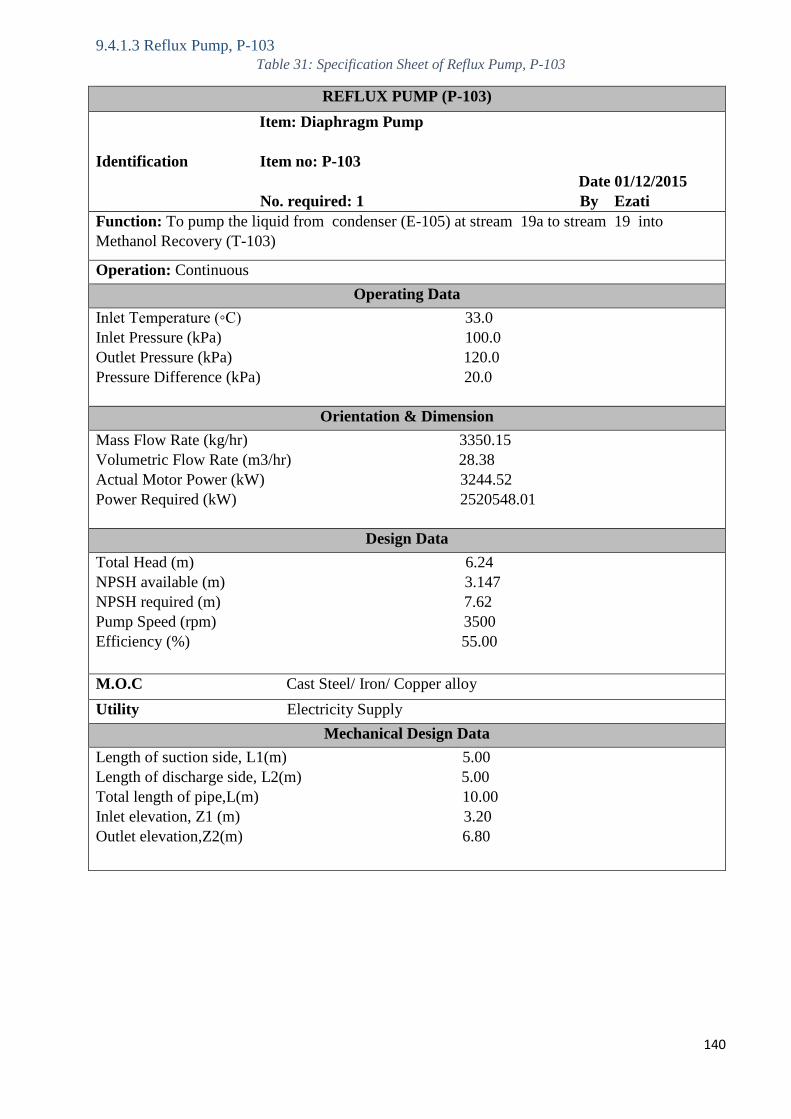
140
9.4.1.3 Reflux Pump, P-103
Table 31: Specification Sheet of Reflux Pump, P-103
REFLUX PUMP (P-103)
Item: Diaphragm Pump
Identification Item no: P-103
Date 01/12/2015
No. required: 1 By Ezati
Function: To pump the liquid from condenser (E-105) at stream 19a to stream 19 into
Methanol Recovery (T-103)
Operation: Continuous
Operating Data
Inlet Temperature (◦C) 33.0
Inlet Pressure (kPa) 100.0
Outlet Pressure (kPa) 120.0
Pressure Difference (kPa) 20.0
Orientation & Dimension
Mass Flow Rate (kg/hr) 3350.15
Volumetric Flow Rate (m3/hr) 28.38
Actual Motor Power (kW) 3244.52
Power Required (kW) 2520548.01
Design Data
Total Head (m) 6.24
NPSH available (m) 3.147
NPSH required (m) 7.62
Pump Speed (rpm) 3500
Efficiency (%) 55.00
M.O.C Cast Steel/ Iron/ Copper alloy
Utility Electricity Supply
Mechanical Design Data
Length of suction side, L1(m) 5.00
Length of discharge side, L2(m) 5.00
Total length of pipe,L(m) 10.00
Inlet elevation, Z1 (m) 3.20
Outlet elevation,Z2(m) 6.80
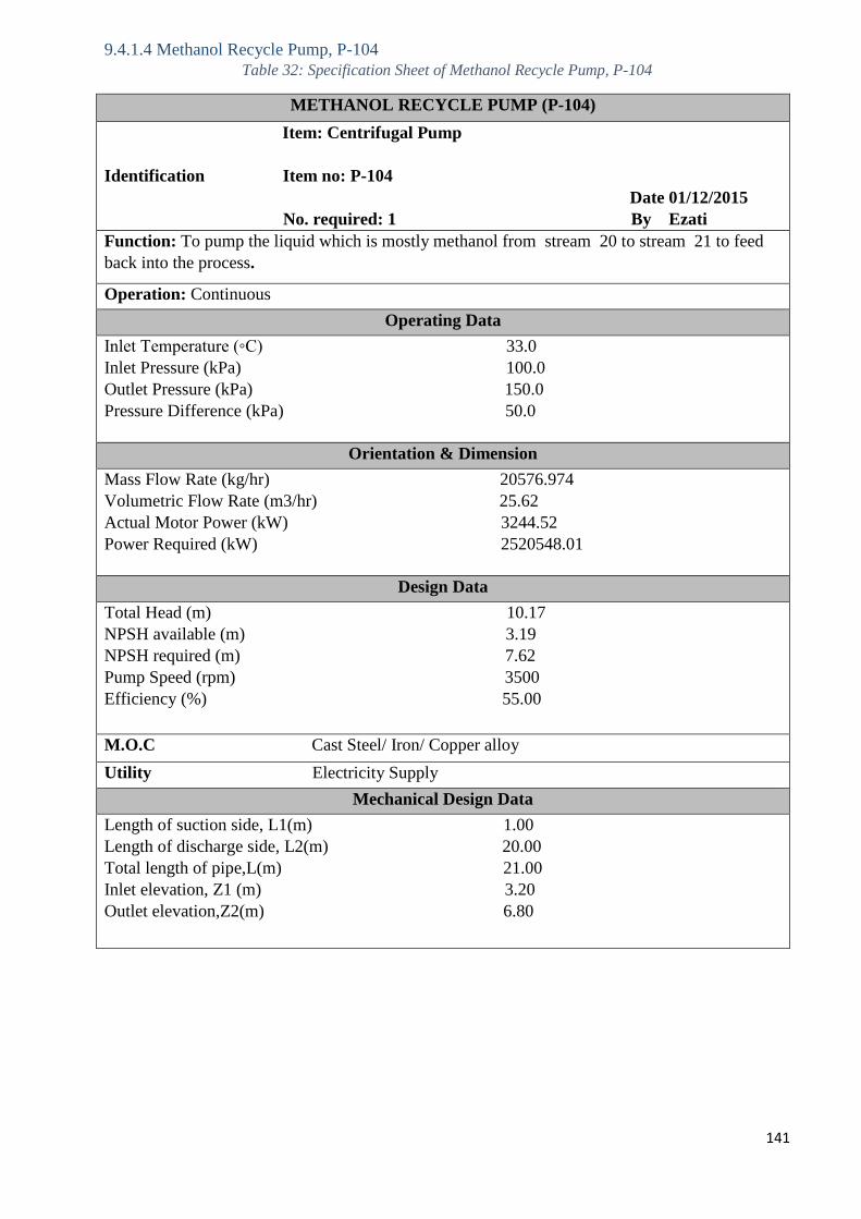
141
9.4.1.4 Methanol Recycle Pump, P-104
Table 32: Specification Sheet of Methanol Recycle Pump, P-104
METHANOL RECYCLE PUMP (P-104)
Item: Centrifugal Pump
Identification Item no: P-104
Date 01/12/2015
No. required: 1 By Ezati
Function: To pump the liquid which is mostly methanol from stream 20 to stream 21 to feed
back into the process.
Operation: Continuous
Operating Data
Inlet Temperature (◦C) 33.0
Inlet Pressure (kPa) 100.0
Outlet Pressure (kPa) 150.0
Pressure Difference (kPa) 50.0
Orientation & Dimension
Mass Flow Rate (kg/hr) 20576.974
Volumetric Flow Rate (m3/hr) 25.62
Actual Motor Power (kW) 3244.52
Power Required (kW) 2520548.01
Design Data
Total Head (m) 10.17
NPSH available (m) 3.19
NPSH required (m) 7.62
Pump Speed (rpm) 3500
Efficiency (%) 55.00
M.O.C Cast Steel/ Iron/ Copper alloy
Utility Electricity Supply
Mechanical Design Data
Length of suction side, L1(m) 1.00
Length of discharge side, L2(m) 20.00
Total length of pipe,L(m) 21.00
Inlet elevation, Z1 (m) 3.20
Outlet elevation,Z2(m) 6.80
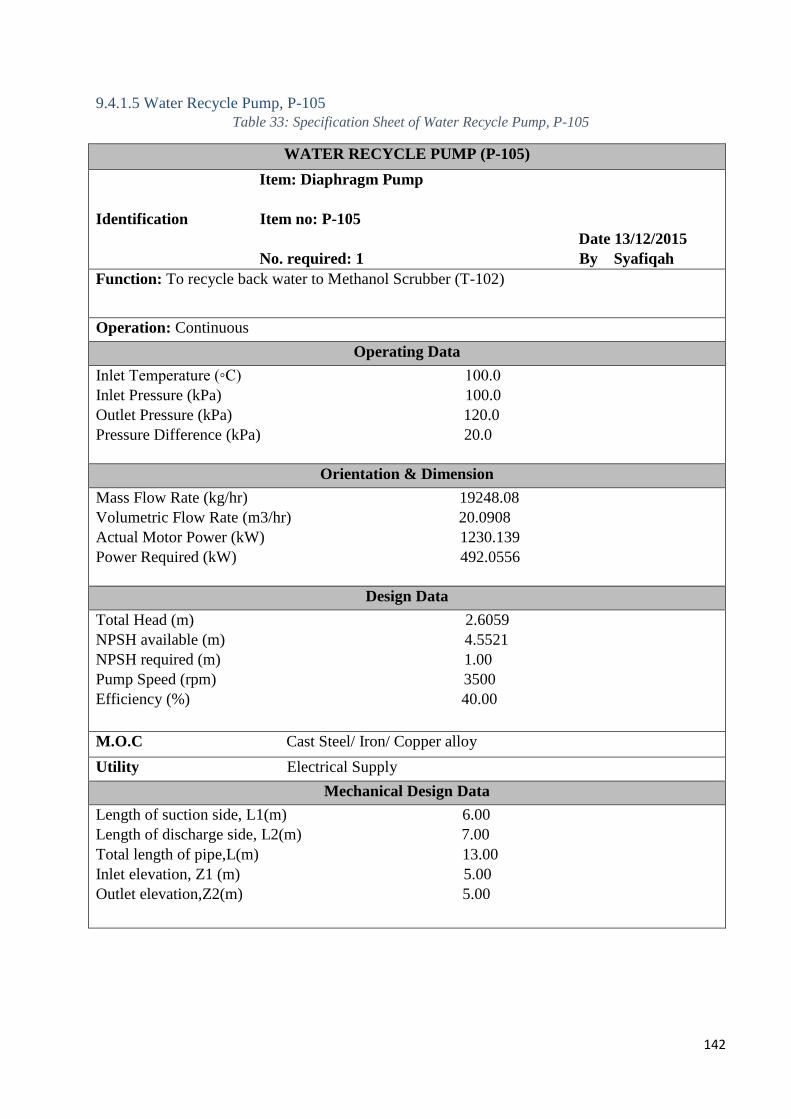
142
9.4.1.5 Water Recycle Pump, P-105
Table 33: Specification Sheet of Water Recycle Pump, P-105
WATER RECYCLE PUMP (P-105)
Item: Diaphragm Pump
Identification Item no: P-105
Date 13/12/2015
No. required: 1 By Syafiqah
Function: To recycle back water to Methanol Scrubber (T-102)
Operation: Continuous
Operating Data
Inlet Temperature (◦C) 100.0
Inlet Pressure (kPa) 100.0
Outlet Pressure (kPa) 120.0
Pressure Difference (kPa) 20.0
Orientation & Dimension
Mass Flow Rate (kg/hr) 19248.08
Volumetric Flow Rate (m3/hr) 20.0908
Actual Motor Power (kW) 1230.139
Power Required (kW) 492.0556
Design Data
Total Head (m) 2.6059
NPSH available (m) 4.5521
NPSH required (m) 1.00
Pump Speed (rpm) 3500
Efficiency (%) 40.00
M.O.C Cast Steel/ Iron/ Copper alloy
Utility Electrical Supply
Mechanical Design Data
Length of suction side, L1(m) 6.00
Length of discharge side, L2(m) 7.00
Total length of pipe,L(m) 13.00
Inlet elevation, Z1 (m) 5.00
Outlet elevation,Z2(m) 5.00
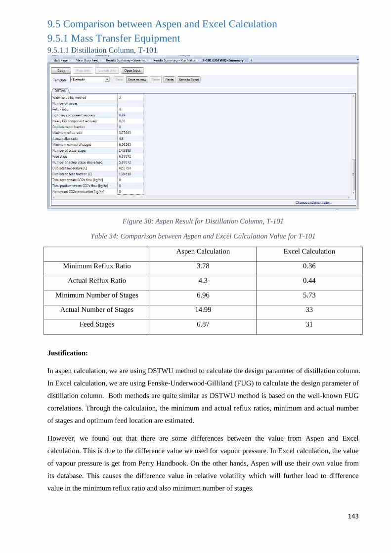
143
9.5 Comparison between Aspen and Excel Calculation
9.5.1 Mass Transfer Equipment 9.5.1.1 Distillation Column, T-101
Figure 30: Aspen Result for Distillation Column, T-101
Table 34: Comparison between Aspen and Excel Calculation Value for T-101
Aspen Calculation Excel Calculation
Minimum Reflux Ratio 3.78 0.36
Actual Reflux Ratio 4.3 0.44
Minimum Number of Stages 6.96 5.73
Actual Number of Stages 14.99 33
Feed Stages 6.87 31
Justification:
In aspen calculation, we are using DSTWU method to calculate the design parameter of distillation column.
In Excel calculation, we are using Fenske-Underwood-Gilliland (FUG) to calculate the design parameter of
distillation column. Both methods are quite similar as DSTWU method is based on the well-known FUG
correlations. Through the calculation, the minimum and actual reflux ratios, minimum and actual number
of stages and optimum feed location are estimated.
However, we found out that there are some differences between the value from Aspen and Excel
calculation. This is due to the difference value we used for vapour pressure. In Excel calculation, the value
of vapour pressure is get from Perry Handbook. On the other hands, Aspen will use their own value from
its database. This causes the difference value in relative volatility which will further lead to difference
value in the minimum reflux ratio and also minimum number of stages.
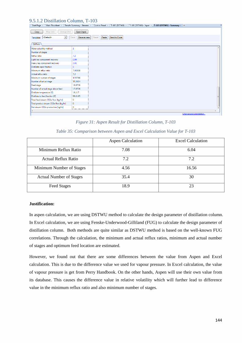
144
9.5.1.2 Distillation Column, T-103
Figure 31: Aspen Result for Distillation Column, T-103
Table 35: Comparison between Aspen and Excel Calculation Value for T-103
Aspen Calculation Excel Calculation
Minimum Reflux Ratio 7.08 6.04
Actual Reflux Ratio 7.2 7.2
Minimum Number of Stages 4.56 16.56
Actual Number of Stages 35.4 30
Feed Stages 18.9 23
Justification:
In aspen calculation, we are using DSTWU method to calculate the design parameter of distillation column.
In Excel calculation, we are using Fenske-Underwood-Gilliland (FUG) to calculate the design parameter of
distillation column. Both methods are quite similar as DSTWU method is based on the well-known FUG
correlations. Through the calculation, the minimum and actual reflux ratios, minimum and actual number
of stages and optimum feed location are estimated.
However, we found out that there are some differences between the value from Aspen and Excel
calculation. This is due to the difference value we used for vapour pressure. In Excel calculation, the value
of vapour pressure is get from Perry Handbook. On the other hands, Aspen will use their own value from
its database. This causes the difference value in relative volatility which will further lead to difference
value in the minimum reflux ratio and also minimum number of stages.
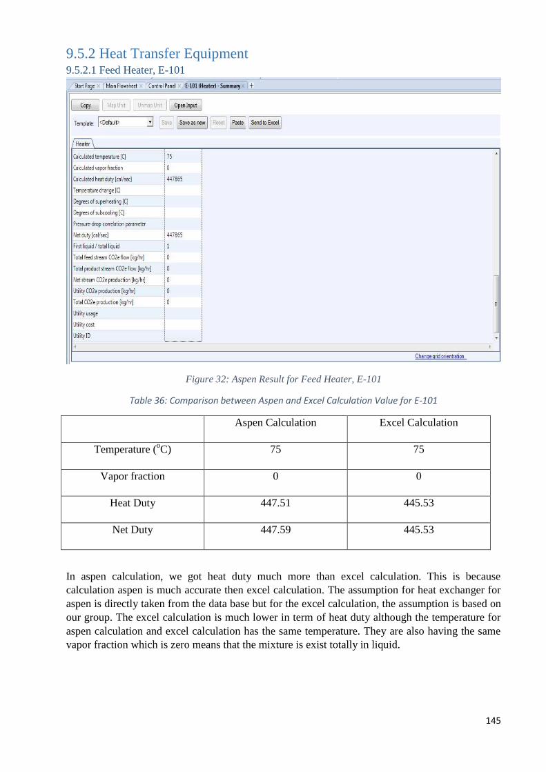
145
9.5.2 Heat Transfer Equipment 9.5.2.1 Feed Heater, E-101
Figure 32: Aspen Result for Feed Heater, E-101
Table 36: Comparison between Aspen and Excel Calculation Value for E-101
Aspen Calculation Excel Calculation
Temperature (oC) 75 75
Vapor fraction 0 0
Heat Duty 447.51 445.53
Net Duty 447.59 445.53
In aspen calculation, we got heat duty much more than excel calculation. This is because
calculation aspen is much accurate then excel calculation. The assumption for heat exchanger for
aspen is directly taken from the data base but for the excel calculation, the assumption is based on
our group. The excel calculation is much lower in term of heat duty although the temperature for
aspen calculation and excel calculation has the same temperature. They are also having the same
vapor fraction which is zero means that the mixture is exist totally in liquid.
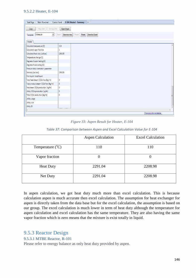
146
9.5.2.2 Heater, E-104
Figure 33: Aspen Result for Heater, E-104
Table 37: Comparison between Aspen and Excel Calculation Value for E-104
Aspen Calculation Excel Calculation
Temperature (oC) 110 110
Vapor fraction 0 0
Heat Duty 2291.04 2208.98
Net Duty 2291.04 2208.98
In aspen calculation, we got heat duty much more than excel calculation. This is because
calculation aspen is much accurate then excel calculation. The assumption for heat exchanger for
aspen is directly taken from the data base but for the excel calculation, the assumption is based on
our group. The excel calculation is much lower in term of heat duty although the temperature for
aspen calculation and excel calculation has the same temperature. They are also having the same
vapor fraction which is zero means that the mixture is exist totally in liquid.
9.5.3 Reactor Design 9.5.3.1 MTBE Reactor, R-101
Please refer to energy balance as only heat duty provided by aspen.
147
References 1. Johann Haltermann, Ltd. ; Technical Data & Safety Bulletin of MTBE;
[Online, Accessed On: 10th
September 2015] Available From:
http://www.monumentchemical.com/documents/MTBE_Data_and_Safety_Sheet.pdf
2. TolgaTopgul; The effects of MTBE blends on engine performance and exhaust emissions in
a spark ignition engine, 2015
3. Agency for Toxic Substances and Disease Registry; Chemical and Physical Information of
MTBE [Online, Accessed On: 10th
September 2015], Available From:
http://www.atsdr.cdc.gov/toxprofiles/tp91-c3.pdf
4. Grand View Research (Market Research & Consulting); 2014; Methyl Tertiary Butyl Ether
(MTBE) Market Analysis, Market Size, Application Analysis, Regional Outlook,
Competitive Strategies And Forecasts, 2014 To 2020 [Online, Accessed On: 11th
September
2015], Available From: http://www.grandviewresearch.com/industry-analysis/methyl-
tertiary-butyl-ether-mtbe-market
5. Chemicalland21; Methyl Tert-Butyl Ether Properties [Online, Accessed On: 13th
September
2015], Available From:
http://www.chemicalland21.com/industrialchem/solalc/METHYL%20TERT-
BUTYL%20ETHER.htm
6. Handbook of MTBE and Other Gasoline Oxygenates, Halim Hamid, Mohammed Ashraf Ali;
Marcel Dekker, Inc. New York; 2004.
7. Fuel-Testers, a division of MLR Solutions; MTBE & Ethanol [Online, Accessed On: 13th
September 2015], Available From:
http://www.fuel-testers.com/ethanol_mtbe_vs_non_alcohol_gas.html
8. CalGasoline, James S. White; Ethanol Is Not a Suitable Replacement for MTBE [Online,
Accessed On: 13th
September 2015], Available From:
http://www.calgasoline.com/factetha.htm
9. The European Fuel Oxygenates Association (EFOA), MTBE Resource Guide, Belgium
2002. E-book. [Online, Accessed On: 14th
September 2015], Available From:
http://www.unep.org/transport/pcfv/PDF/PubEFOAMTBE.pdf
10. Malaysia Petroleum Resources Corporation; The Oil & Gas Year (Malaysia 2015), The
Who’s Who of the Global Energy Industry [Online, Accessed On: 14th
September 2015],
Available From:
http://www.theoilandgasyear.com/content/uploads/2015/04/TOGY_MALAYSIA_2015.pdf
148
11. Official Website of Malaysian Investment Development Authority (MIDA) [Online,
Accessed On: 14th
September 2015], Available From:
http://www.mida.gov.my/home/oil-and-gas/posts/
12. Halim Hong & Quek Advocates & Solicitors; Malaysia’s Oil and Gas Industry: A Brief
Legal Introduction; 2014 [Online, Accessed On: 15th
September 2015], Available From:
http://www.hhq.com.my/2014/10/malaysias-oil-and-gas-industry-a-brief-legal-introduction/
13. Joseph Gregor and Daniel Wei, UOP Oleflex Process for Light Olefin Production
14. C, S, HSU and P, Robinson Practical Advances in Petroleum Processing, Volume 1 p. 41.
Publish by Springer Science + Business Media. Inc
15. M.Farsi, Dynamic modeling, simulation and control of isobutene dehydrogenation in a
commercial Oleflex process considering catalyst deactivation
16. Steve Krupa, Jill Meister and Charles Luebke; Handbook of Petroleum Refining Processes,
Chapter 13.2; UOP Ethermax Process for MTBE, ETBE and TAME Production
17. James H. Gary, Glenn E. Handwerk, Mark J. Kaiser; Petroleum Refining: Technology and
Economics, Fifth Edition; 2007.
18. Pierre Fournier, MTBE Synthesis in a Riser Simulator; Faculty of Graduate Studies The
University of Western Ontario London, Ontario, Canada; 1997.
19. Alain Chauvel & Gilles Lefebvre, Petrochemical Processes: Technical and Economic
Characteristics, pg 212; Technip; Paris; 1989.
20. Emir Ceric, Crude Oil, Process and Products, pg148; IBC; Petrolinvest 2012.
21. Fahad S. Al-Harthi, Modeling and Simulation of A Reactive Distillation Unit for Production
of MTBE, 2008.
22. Methyl Tertiary-Butyl Ether (MTBE): Conditions Affecting the Domestic Industry, U.S
INTERNATIONAL TRADE COMMISSION; Publication 3231; Washington; 1999.
23. Giuseppe Messina, et al.; Process for the Direct Hydration of Linear Olefins, EP 0313905
A2; 1989. [Online, Accessed On: 16th
September 2015], Available From:
http://www.google.com/patents/EP0313905A2?cl=en
24. John F. Knifton , John R. Sanderson and Melvin E. Stockton Catalysis Letters Vol. 73, No.
1, 2001
25. Rudolph Rosenthal, Continuous process for dehydration of tertiary butyl alcohol, United
State Patent, US 3510538 A, 1970
26. Matouq, M. H., and Shigeo, G., Int. J. Chem. Kinet. 25, 825; 1993
27. John Frederick Knifton; Method for One-Step Synthesis of Methyl T-Butyl; 1993 [Online,
Accessed On: 16th
September 2015], Available From:
http://www.google.com/patents/EP0333076B1?cl=en
28. Basic Principles of Organic Chemistry by John D. Roberts; 1977
149
29. Mohammed Matouq et al. Combined process for production of Methyl Tert-Butyl Ether
from Tert-Butyl Alcohol and Methanol, Journal of Chemical Engineering of Japan, Vol.27
No.3,302-307; 1994
30. Zhang Ziyang et al.,Determination of Adsorption and Kinetic Parameters for Methyl tert-
Butyl Ether Synthesis from tert-Butyl Alcohol and Methanol, Journal of Catalysis 200, 209–
221; 2001
31. Charles J. Kruse; Method for the Manufacture and Recovery of Methyl Tertiary Butyl Ether;
1993 [Online, Accessed On: 16th
September 2015], Available From:
http://www.google.com/patents/US5243091
32. Office of Pollution Prevention and Toxics U.S. Environmental Protection Agency; August
1994 [Online, Accessed On: 17th
September 2015], Available From:
http://www.epa.gov/chemfact/f_mtbe.txt
33. ChemPRIME; Properties of Alkanes in the Environment; 2012 [Online, Accessed On: 17th
September 2015]. Available From:
http://wiki.chemprime.chemeddl.org/index.php/Properties_of_Alkanes_in_the_Environment
34. LyondellBasell; Global Product Strategy (GPS) Safety Summary for Diisobutylene; 2015
35. Dimethyl Ether Product Safety Summary
36. Edward C. Nelson, David A. Storm, Mahendra S. Patel; Preparation of MTBE from TBA
and Methanol; 1990 [Online, Accessed On: 18th
September 2015], Available From:
http://www.google.com/patents/US4918244
37. Cameo Chemicals, Database of Hazardous Materials [Online, Accessed On: 18th
September
2015], Available From: http://cameochemicals.noaa.gov/
38. Lyonfellbasell, Global Product Strategy Safety Summary of TBA[Online, Accessed On: 18th
September 2015], Available From:
http://www.lyondellbasell.com/techlit/techlit/GPS%20Safety%20Summaries%20PDF/Tertia
ry_Butyl_Alcohol_GPS_Safety_Summary.pdf
39. State Water Resources Control, Board Division of Water Quality. GAMA Program;
Groundwater Information Sheet for MTBE; 2010
40. MTBE, American Cancer Society[Online, Accessed On: 19th
September 2015], Available
From:
http://www.cancer.org/cancer/cancercauses/othercarcinogens/pollution/mtbe
41. ICIS, Trusted market intelligence for the global chemical, energy and fertilizer industries;
Indicative Chemical Prices A-Z [Online, Accessed On: 18th
September 2015], Available
From: http://www.icis.com/chemicals/channel-info-chemicals-a-z/
42. Article on Butane Source [Online, Accessed On: 18th
September 2015], Available From:
https://butanesource.com/blog/79-how-butane-is-made
150
43. Malaysia International Energy Data and Analysis [Online, Accessed On: 19th
September
2015], Available From:
http://www.eia.gov/beta/international/analysis.cfm?iso=MYS
44. ICLG, International Comparative Legal Guides[Online, Accessed On:19th
September 2015],
Available From: http://www.iclg.co.uk/practice-areas/oil-and-gas-regulation/oil-and-gas-
45. Indexmundi [Online, Accessed On: 20th
September 2015], Available From:
http://www.indexmundi.com/g/g.aspx?c=my&v=88
46. Honeywell’s UOP [Online, Accessed On: 21st September 2015], Available From:
http://www.uop.com/?press_release=honeywells-uop-selected-to-provide-technology-for-
petrochemical-production-in-china-4
47. LyondellBasell [Online, Accessed On: 21st September 2015], Available From:
http://www.lyondellbasell.com/Products/ByCategory/basicchemicals/IntermediateChemical
sAndGlycols/PropyleneOxide/
48. Argus DeWitt 2015 Fuels and Oxygenates Annual [Online, Accessed On: 21st September
2015], Available From:
https://www.argusmedia.com/Petrochemicals/~/media/6FC9ED773C374326806BB2B3678
4C1B8.ashx
49. MTBE Market Growth, Outlook and Forecast to 2020 [Online, Accessed On: 21st
September 2015], Available From: https://www.linkedin.com/pulse/methyl-tertiary-butyl-
ether-mtbe-market-growth-2020-chakravorty
50. Oil & Gas Journal [Online, Accessed On: 25th
September 2015], Available From:
http://www.ogj.com/articles/2004/01/us-officials-to-investigate-mtbe-po-plant-fire.html
51. Minding the Bottom-line [Online, Accessed On: 22nd
September 2015], Available From:
http://www.terengganu.gov.my/maxc2020/appshare/widget/mn_img/1/CP-
8%20HAVEN%20%2707%20CO.pdf
52. Grange Resources Limited [Online, Accessed On: 22nd
September 2015], Available From:
http://www.asx.com.au/asxpdf/20110510/pdf/41ykpdksjvjq63.pdf
53. Press Center Projects [Online, Accessed On: 22nd
September 2015], Available From:
http://sibur.com/press_center/projects/15371/
54. New MTBE Global Markets to 2020 [Online, Accessed On: 22nd
September 2015],
Available From:
http://www.prweb.com/releases/2013/MethylTertiaryButylEther/prweb10721354.htm
55. Malaysia New Vehicles Registered [Online, Accessed On: 22nd
September 2015], Available
From:
http://www.tradingeconomics.com/malaysia/car-registrations
151
56. Malaysia Motor Gasoline Consumption by Year [Online, Accessed On: 22nd
September
2015], Available From:
http://www.indexmundi.com/energy.aspx?country=my&product=gasoline&graph=consump
tion
57. Merchant Research & Consulting ltd [Online, Accessed On: 22nd
September 2015],
Available From: http://mcgroup.co.uk/news/20141128/global-mtbe-consumption-continue-
dropping-upcoming-years.html
58. MTBE and Clean Gasoline in Asia [Online, Accessed On: 22nd
September 2015], Available
From:
http://www.acfa.org.sg/pdf/PastEvent_Kuantan_Malaysia_June2012_ACFA_EN.pdf
59. K.E Porter, Distillation and Absorption Volume 1; Institution of Chemical Engineering;
Rugby, UK; 1992.
60. TAPC, Gas Scrubbing- Absorption and Stripping [Online, Accessed On: 23rd
September
2015], Available From: http://www.tapc.com.au/gas/absorption.html
61. SRS Engineering Biodiesel [Online, Accessed On: 24th
September 2015], Available From:
http://www.srsengineering.com/our-products/distillation-columns/
62. PRO/II Casebook Methyl Tertiary Butyl Ether (MTBE) Plant; Simulation Science Inc.; 1995
63. Lyondellbasell; Material Safety Data Sheet of Isobutylene [Online, Accessed On: 20th
September 2015], Available From:
http://www.lyondellbasell.com/techlit/techlit/REACH_docs/isobutylene.pdf
64. Methanex, A Responsible Care Company; Methanol MSDS [Online, Accessed On: 20th
September 2015], Available From:http://www.methanol.org/getattachment/b327897d-cbdd-
4c9a-abc3-43d5a1590ce6/NorthAm_SDS_English-(1).pdf.aspx
65. ScienceLab; Material Safety Data Sheet, Methyl tert-butyl ether MSDS [Online, Accessed
On: 20th
September 2015], Available
From:http://www.sciencelab.com/msds.php?msdsId=9927229
66. MSDS of 2,4,4-Trimethyl-1-pentene [Online, Accessed On: 20th
September 2015],
Available From:
https://www.fishersci.com/shop/msdsproxy?productName=AC407780010&productDescript
ion=DIISOBUTYLENE+(PRACT)%2C+9+1KG&catNo=AC40778-
0010&vendorId=VN00032119&storeId=10652
67. R, H, Perry and D, W, Green Perry’s Chemical Engineers’ Handbook.P. 245. Publish by
The McGRAW. HILL Companies, Inc.
68. MSDS of Water [Online, Accessed On: 2oth September 2015], Available From:
https://www.sciencelab.com/msds.php?msdsId=9927321
152
69. MSDS of Methyl alcohol [Online, Accessed On: 20th
September 2015], Available From:
http://www.sciencelab.com/msds.php?msdsId=9927227
70. SDS of Isobutylene [Online, Accessed On: 20th
September 2015], Available From:
http://www.praxair.com/~/media/North%20America/US/Documents/SDS/Isobutylene%20C
4H8%20Safety%20Data%20Sheet%20SDS%20P4614.pdf
71. MSDS of 2,4,4-Trimethyl-1-pentene [Online, Accessed On: 20th
September 2015],
Available From: http://www.sciencelab.com/msds.php?msdsId=9925334
72. SDS of Dimethyl Ether [Online, Accessed On: 20th
September 2015], Available From:
http://www.chemadvisor.com/Matheson/database/msds/00244291000800003.PDF
73. MSDS of tert-Butyl alcohol [Online, Accessed On: 20th
September 2015], Available From:
http://www.sciencelab.com/msds.php?msdsId=9923195
74. MSDS of H2O [Online, Accessed On: 20th
September 2015], Available From:
https://www.sciencelab.com/msds.php?msdsId=9927321
75. Methyl Tertiary Butyl Ether (MTBE) Petrochemical Plant at Gebeng, Kuantan; PETRONAS
MALAYSIA [Online, Accessed On: 23rd
September 2015], Available From:
http://www.petronas.com.my/our-business/downstream/petro-chemicals/gebeng-
ipc/Pages/gebeng-ipc/petrochemical-plants-gebeng.aspx
76. The MTBE Resource Guide, published by The European Fuel Oxygenates Association
(EFOA), 2002 [Online, Accessed On: 27th
September 2015], Available From:
http://www.unep.org/transport/pcfv/PDF/PubEFOAMTBE.pdf
77. Agency for Toxic Substances and Disease Registry (Atsdr); Toxic Substances Portal -
Methyl tert-Butyl Ether (MTBE); Public Health Statement for Methyl-tert-butyl Ether
[Online, Accessed On: 27th
Septemeber 2015], Available From:
http://www.atsdr.cdc.gov/phs/phs.asp?id=226&tid=41
78. American Cancer Society, Inc.; MTBE; 2014 [Online, Accessed On: 27th
Septemeber 2015],
Available From:
http://www.cancer.org/cancer/cancercauses/othercarcinogens/pollution/mtbe
79. MTBE Fact Sheet #2: Remediation Of MTBE Contaminated Soil And Groundwater, by U.S
EPA[Online, Accessed On: 27th
September 2015], Available From: https://clu-
in.org/download/toolkit/mtbefs2.pdf
80. MSDS of isobutylene [Online, Accessed On: 27th
September 2015], Available From:
https://www.mesagas.com/images/Isobutylene.pdf
81. MTBE- Well Water and What To Do About This Ground Water Contaminant [Online,
Accessed On: 27th
September 2015], Available From: http://blog.skillingsandsons.com/blog-
1/bid/354409/MTBE-Well-Water-and-What-To-Do-About-This-Ground-Water-
Contaminant
153
82. American Cancer Society, Inc.; MTBE POLLUTION [Online, Accessed On: 27th
September
2015], Available From:
http://www.cancer.org/cancer/cancercauses/othercarcinogens/pollution/mtbe].
83. Wanhua Chemical Group Co.,Ltd.; Purity of the Product (MTBE) [Online, Accessed On:
27th
September 2015], Available From:
http://www.whchem.com/en/productsservice/product/1312.shtml
84. Merchant Research & Consulting, Ltd.; Methyl Tertiary Butyl Ether (MTBE): 2015 World
Market Outlook and Forecast up to 2019; 2015 [Online, Accessed On: 27th
September 2015],
Available From: http://mcgroup.co.uk/researches/methyl-tertiary-butyl-ether-mtbe
85. GBI Research; Methyl Tertiary Butyl Ether (MTBE) Global Markets to 2020 - China
Dominates Global MTBE Demand While Developed Regions Look to ETBE and Ethanol as
Replacement Options [Online, Accessed On: 27th
September 2015], Available From:
http://www.chemie.de/marktstudien/12275/methyl-tertiary-butyl-ether-mtbe-global-markets-
to-2020-china-dominates-global-mtbe-demand-while-developed-regions-look-to-etbe-and-
ethanol-as-replacement-options.html
86. Business Wire; Research and Markets: China Methyl Tert-Butyl Ether (MTBE) Markets
Outlook 2014-2018 & 2023; 2014 [Online, Accessed On: 27th
September 2015], Available
From:
http://www.businesswire.com/news/home/20141107005153/en/Research-Markets-China-
Methyl-Tert-Butyl-Ether-MTBE#.VgTzoMuqqko
87. Production of MTBE in China for Next Decade [Online, Accessed On: 27th
September
2015], Available From: http://www.giiresearch.com/report/amid71690-cn-mtbe.html
88. MTBE Market Growth Analysis [Online, Accessed On: 27th
September 2015], Available
From: https://www.linkedin.com/pulse/methyl-tertiary-butyl-ether-mtbe-market-growth-
analysis-sherry-james
89. Economy of China Online, Accessed On: 27th
September 2015], Available From:
http://www.worldbank.org/en/country/china/overview
90. Saudi International Petrochemical Company [Online, Accessed On: 25th September 2015],
Available From: http://www.sipchem.com/pdf/products/basic/methanol-spec-sheet.pdf
91. U.S Sales Specification, Lyondell Online, Accessed On: 25th September 2015], Available
From: http://www.lyondellbasell.com/techlit/techlit/SalesSpecs/2147.pdf]
92. MTBE Test Method Specification MTBE [Online, Accessed On 27th
September 2015],
Available From: http://www.bharatpetroleum.com/pdf/MRL_MTBE.pdf
93. Isobutylene’s price [Online, Accessed On 27th
September 2015], Available From:
http://www.icis.com/chemicals/channel-info-chemicals-a-z/
154
94. Methanol’s price [Online, Accessed On 27th
September 2015], Available From:
https://www.methanex.com/sites/default/files/methanol-price/Mx-Price-Sheet-2015-08-
31.pdf
95. MTBE’s price [Online, Accessed On 27th
September 2015], Available From:
http://www.icis.com/chemicals/channel-info-chemicals-a-z/
96. Disobutylene’s Price [Online, Accessed On 27th
September 2015], Available From:
http://www.sigmaaldrich.com/catalog/search?term=diisobutylene&interface=All&N=0&mo
de=match%20partialmax&lang=en®ion=MY&focus=product
97. Competitive Dimethyl Ether Price [Online, Accessed On 27th
September 2015], Available
From: http://www.alibaba.com/product-detail/Competitive-dimethyl-ether-
prices_1513621496.html?spm=a2700.7724838.30.48.zWgfV9
98. Best Price Tert-butyl alcohol High Purity [Online, Accessed On 27th
September 2015],
Available From: http://www.alibaba.com/product-detail/Best-Price-Tert-butyl-alcohol-
High_60328265543.html?spm=a2700.7724838.30.52.E1888k
99. Maklumat Am [Online, Accessed On 27th
September 2015], Available From:
http://www.satuwater.com.my/index.php/jadual-kod-tarif
100. Utilities of the Process[Online, Accessed On 24th
September 2015], Available From
http://websols.com/terengganu/html/infrastructure_facts.html
101. The mixed C4’s stream refer to a mixture of isobutylene, butene, butane, propane, and sulfur
[Online, Accessed On 27th
September 2015], Available From:
http://www.praxair.com/~/media/North%20America/US/Documents/Specification%20Sheet
s%20and%20Brochures/Gases/Isobutylene%20C4H8%20Spec%20Sheet%20SS%20P4614.
102. MTBE Production using Methanol and Isobutylene [Online, Accessed On 27th
September
2015], Available From:
http://www.gasinnovations.com/literature/HYDROCARBON/Isobutylene-C.P.-Grade.pdf
103. F.Collignon et.al, Liquid Phase Synthesis of MTBE from Methanol and Isobutene over Acid
Zeolites and Amberlyst-15, Journal of Catalysis
104. MTBE Synthesis in A Riser Simulators [Online, Accessed On: 22nd
September 2015],
Available From: http://www.collectionscanada.gc.ca/obj/s4/f2/dsk2/ftp01/MQ28568.pdf
105. Andreas Beckmann et.al, Industrial experience in the scale-up of reactive distillation with
examples from C4-chemistry
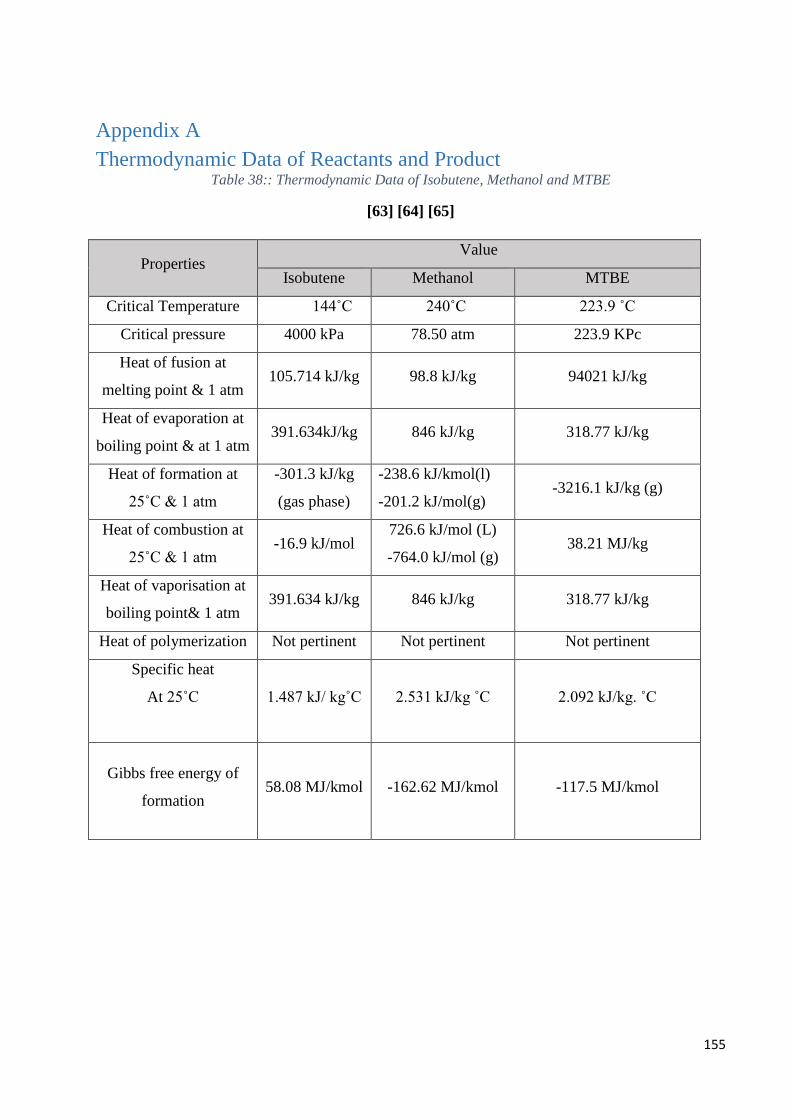
155
Appendix A
Thermodynamic Data of Reactants and Product Table 38:: Thermodynamic Data of Isobutene, Methanol and MTBE
[63] [64] [65]
Properties Value
Isobutene Methanol MTBE
Critical Temperature 144˚C 240˚C 223.9 ˚C
Critical pressure 4000 kPa 78.50 atm 223.9 KPc
Heat of fusion at
melting point & 1 atm 105.714 kJ/kg 98.8 kJ/kg 94021 kJ/kg
Heat of evaporation at
boiling point & at 1 atm 391.634kJ/kg 846 kJ/kg 318.77 kJ/kg
Heat of formation at
25˚C & 1 atm
-301.3 kJ/kg
(gas phase)
-238.6 kJ/kmol(l)
-201.2 kJ/mol(g) -3216.1 kJ/kg (g)
Heat of combustion at
25˚C & 1 atm -16.9 kJ/mol
726.6 kJ/mol (L)
-764.0 kJ/mol (g) 38.21 MJ/kg
Heat of vaporisation at
boiling point& 1 atm 391.634 kJ/kg 846 kJ/kg 318.77 kJ/kg
Heat of polymerization Not pertinent Not pertinent Not pertinent
Specific heat
At 25˚C
1.487 kJ/ kg˚C
2.531 kJ/kg ˚C
2.092 kJ/kg. ˚C
Gibbs free energy of
formation 58.08 MJ/kmol
-162.62 MJ/kmol
-117.5 MJ/kmol
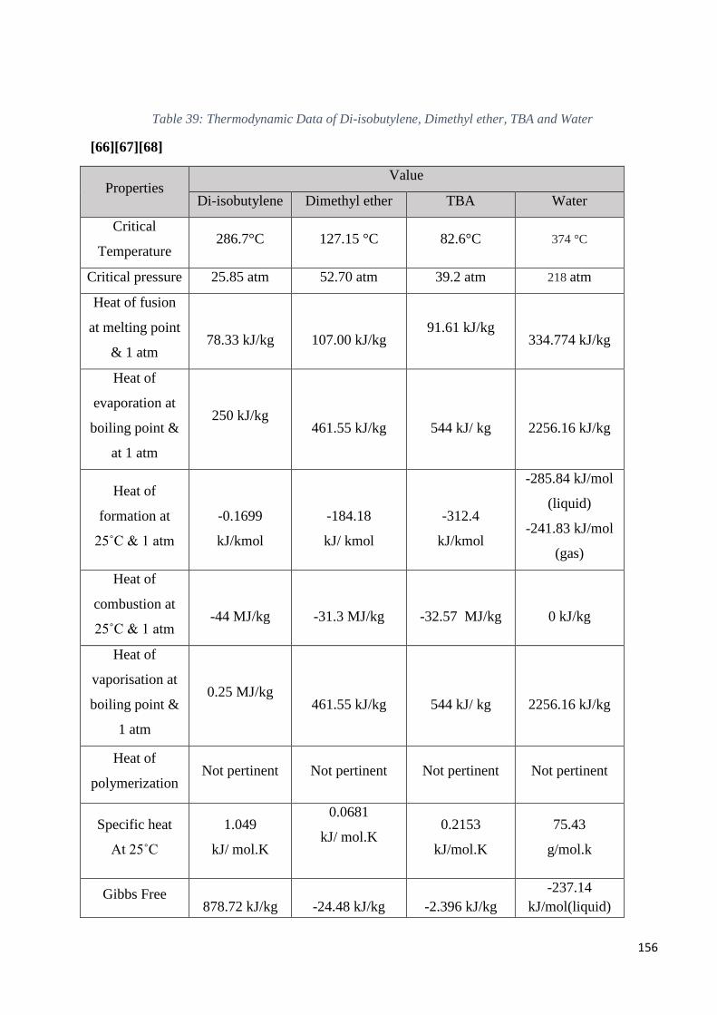
156
Table 39: Thermodynamic Data of Di-isobutylene, Dimethyl ether, TBA and Water
[66][67][68]
Properties Value
Di-isobutylene Dimethyl ether TBA Water
Critical
Temperature 286.7°C 127.15 °C 82.6°C 374 °C
Critical pressure 25.85 atm 52.70 atm 39.2 atm 218 atm
Heat of fusion
at melting point
& 1 atm
78.33 kJ/kg
107.00 kJ/kg
91.61 kJ/kg
334.774 kJ/kg
Heat of
evaporation at
boiling point &
at 1 atm
250 kJ/kg
461.55 kJ/kg
544 kJ/ kg
2256.16 kJ/kg
Heat of
formation at
25˚C & 1 atm
-0.1699
kJ/kmol
-184.18
kJ/ kmol
-312.4
kJ/kmol
-285.84 kJ/mol
(liquid)
-241.83 kJ/mol
(gas)
Heat of
combustion at
25˚C & 1 atm
-44 MJ/kg
-31.3 MJ/kg
-32.57 MJ/kg
0 kJ/kg
Heat of
vaporisation at
boiling point &
1 atm
0.25 MJ/kg
461.55 kJ/kg
544 kJ/ kg
2256.16 kJ/kg
Heat of
polymerization Not pertinent Not pertinent Not pertinent Not pertinent
Specific heat
At 25˚C
1.049
kJ/ mol.K
0.0681
kJ/ mol.K
0.2153
kJ/mol.K
75.43
g/mol.k
Gibbs Free
878.72 kJ/kg
-24.48 kJ/kg
-2.396 kJ/kg
-237.14
kJ/mol(liquid)
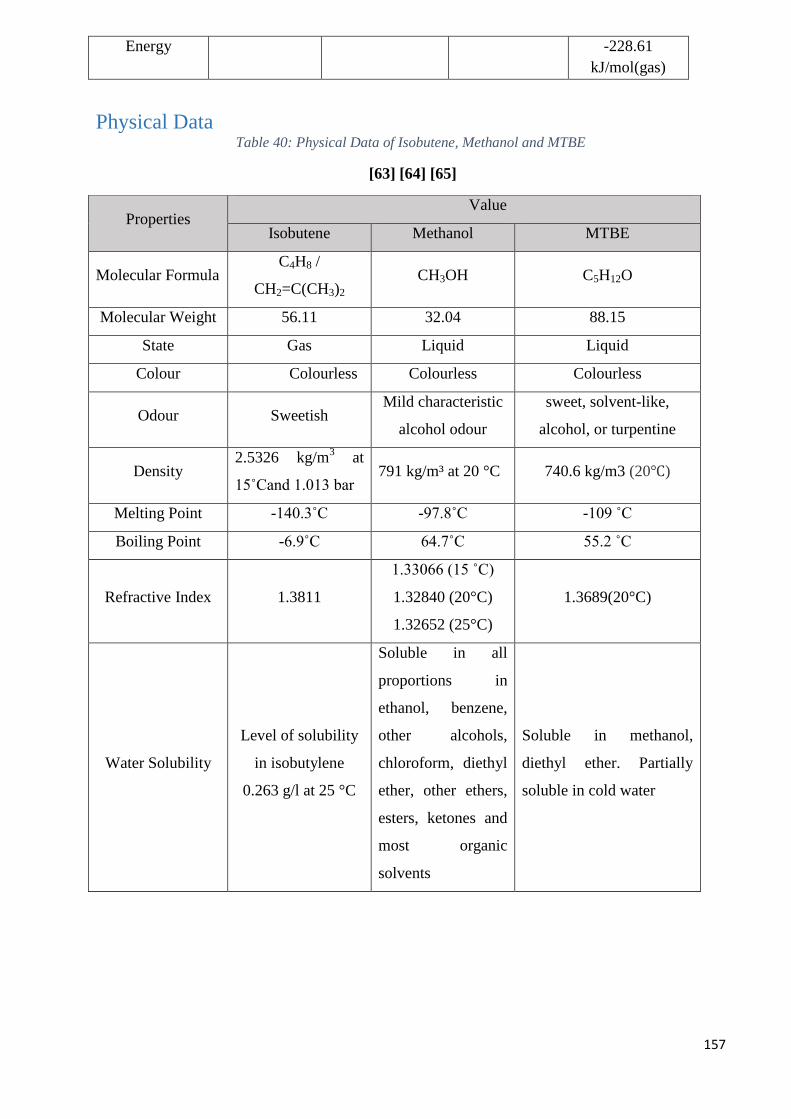
157
Energy -228.61
kJ/mol(gas)
Physical Data Table 40: Physical Data of Isobutene, Methanol and MTBE
[63] [64] [65]
Properties Value
Isobutene Methanol MTBE
Molecular Formula C4H8 /
CH2=C(CH3)2
CH3OH C5H12O
Molecular Weight 56.11 32.04 88.15
State Gas Liquid Liquid
Colour Colourless Colourless Colourless
Odour Sweetish Mild characteristic
alcohol odour
sweet, solvent-like,
alcohol, or turpentine
Density 2.5326 kg/m
3 at
15˚Cand 1.013 bar 791 kg/m³ at 20 °C 740.6 kg/m3 (20℃)
Melting Point -140.3˚C -97.8˚C -109 ˚C
Boiling Point -6.9˚C 64.7˚C 55.2 ˚C
Refractive Index 1.3811
1.33066 (15 ˚C)
1.32840 (20°C)
1.32652 (25°C)
1.3689(20°C)
Water Solubility
Level of solubility
in isobutylene
0.263 g/l at 25 °C
Soluble in all
proportions in
ethanol, benzene,
other alcohols,
chloroform, diethyl
ether, other ethers,
esters, ketones and
most organic
solvents
Soluble in methanol,
diethyl ether. Partially
soluble in cold water
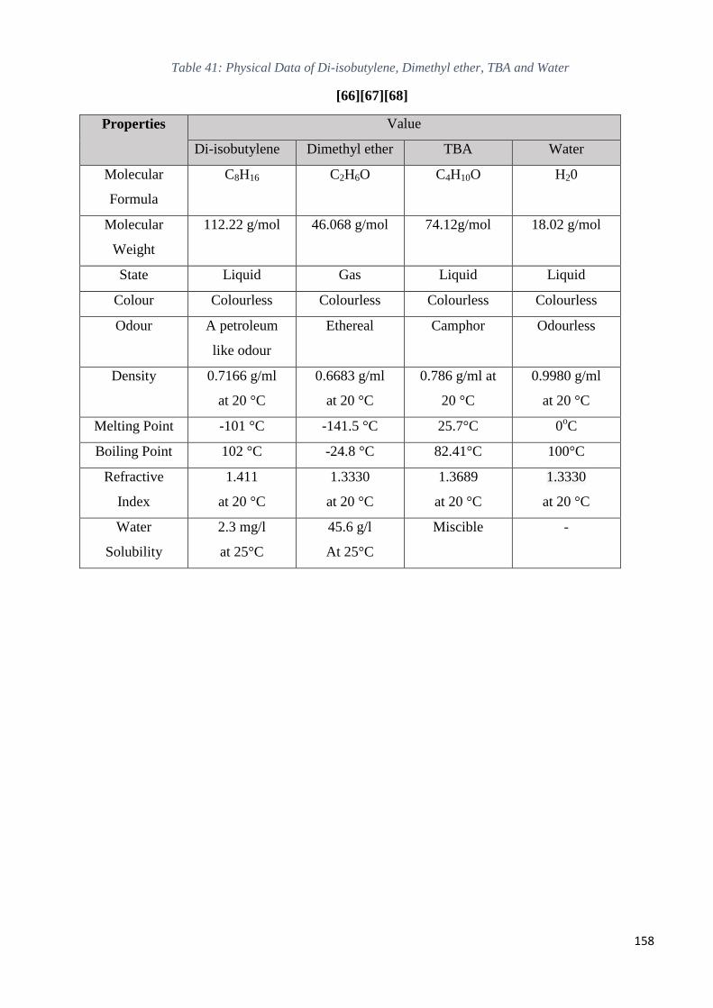
158
Table 41: Physical Data of Di-isobutylene, Dimethyl ether, TBA and Water
[66][67][68]
Properties Value
Di-isobutylene Dimethyl ether TBA Water
Molecular
Formula
C8H16 C2H6O C4H10O H20
Molecular
Weight
112.22 g/mol 46.068 g/mol 74.12g/mol 18.02 g/mol
State Liquid Gas Liquid Liquid
Colour Colourless Colourless Colourless Colourless
Odour A petroleum
like odour
Ethereal Camphor Odourless
Density 0.7166 g/ml
at 20 °C
0.6683 g/ml
at 20 °C
0.786 g/ml at
20 °C
0.9980 g/ml
at 20 °C
Melting Point -101 °C -141.5 °C 25.7°C 0oC
Boiling Point 102 °C -24.8 °C 82.41°C 100°C
Refractive
Index
1.411
at 20 °C
1.3330
at 20 °C
1.3689
at 20 °C
1.3330
at 20 °C
Water
Solubility
2.3 mg/l
at 25°C
45.6 g/l
At 25°C
Miscible -
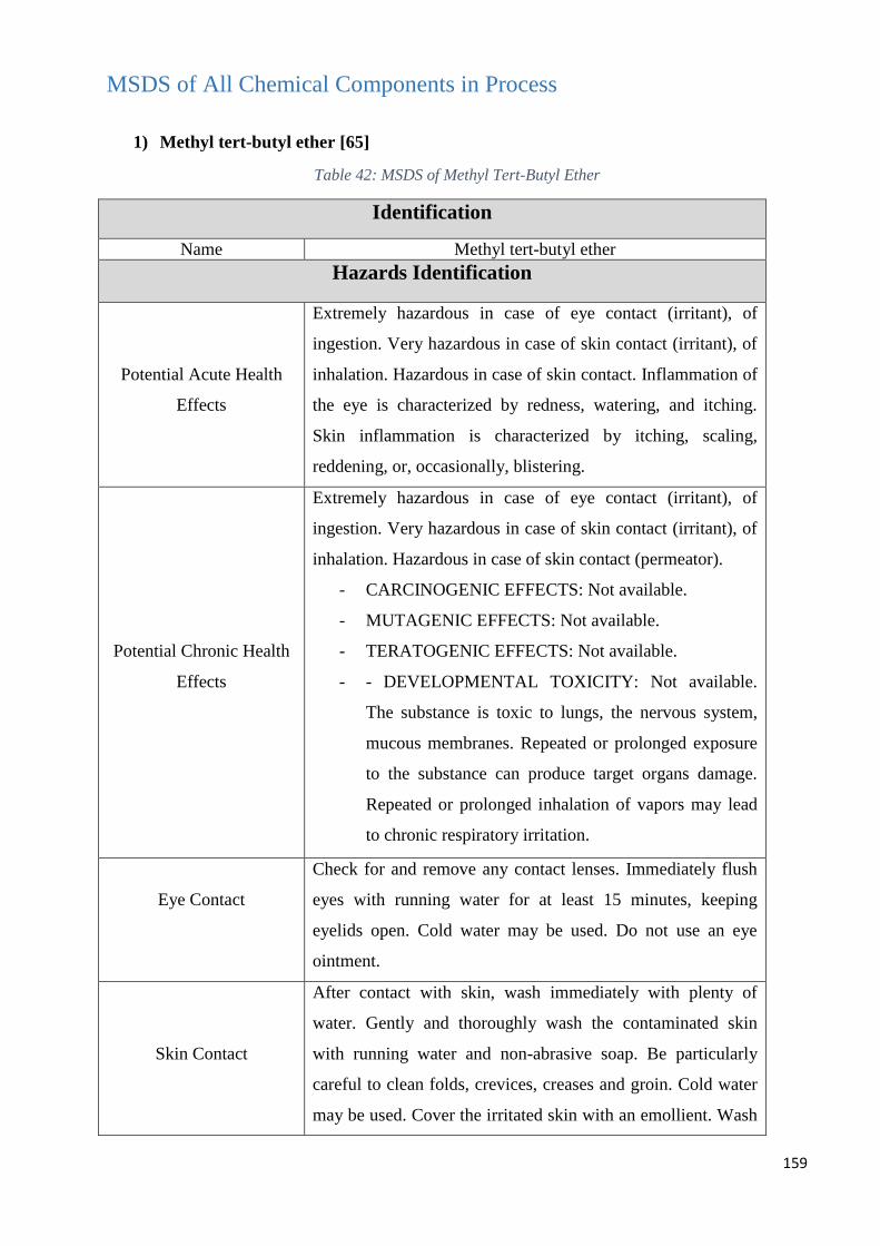
159
MSDS of All Chemical Components in Process
1) Methyl tert-butyl ether [65]
Table 42: MSDS of Methyl Tert-Butyl Ether
Identification
Name Methyl tert-butyl ether
Hazards Identification
Potential Acute Health
Effects
Extremely hazardous in case of eye contact (irritant), of
ingestion. Very hazardous in case of skin contact (irritant), of
inhalation. Hazardous in case of skin contact. Inflammation of
the eye is characterized by redness, watering, and itching.
Skin inflammation is characterized by itching, scaling,
reddening, or, occasionally, blistering.
Potential Chronic Health
Effects
Extremely hazardous in case of eye contact (irritant), of
ingestion. Very hazardous in case of skin contact (irritant), of
inhalation. Hazardous in case of skin contact (permeator).
- CARCINOGENIC EFFECTS: Not available.
- MUTAGENIC EFFECTS: Not available.
- TERATOGENIC EFFECTS: Not available.
- - DEVELOPMENTAL TOXICITY: Not available.
The substance is toxic to lungs, the nervous system,
mucous membranes. Repeated or prolonged exposure
to the substance can produce target organs damage.
Repeated or prolonged inhalation of vapors may lead
to chronic respiratory irritation.
Eye Contact
Check for and remove any contact lenses. Immediately flush
eyes with running water for at least 15 minutes, keeping
eyelids open. Cold water may be used. Do not use an eye
ointment.
Skin Contact
After contact with skin, wash immediately with plenty of
water. Gently and thoroughly wash the contaminated skin
with running water and non-abrasive soap. Be particularly
careful to clean folds, crevices, creases and groin. Cold water
may be used. Cover the irritated skin with an emollient. Wash
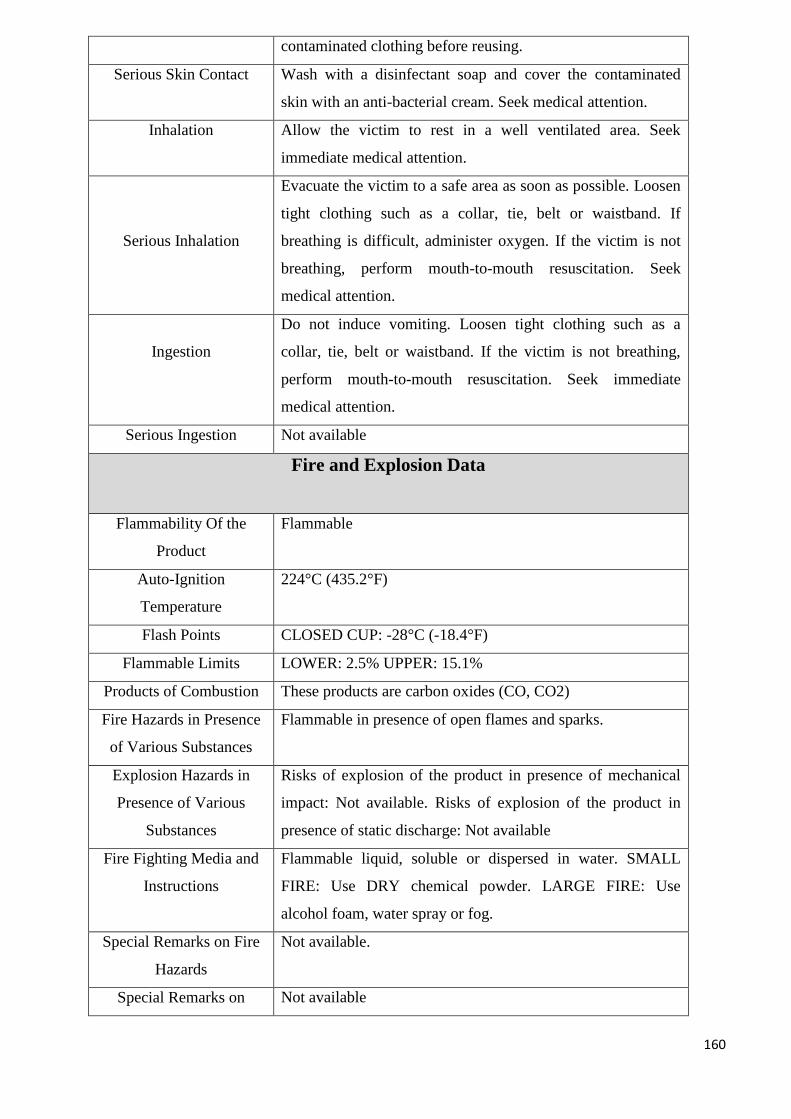
160
contaminated clothing before reusing.
Serious Skin Contact Wash with a disinfectant soap and cover the contaminated
skin with an anti-bacterial cream. Seek medical attention.
Inhalation Allow the victim to rest in a well ventilated area. Seek
immediate medical attention.
Serious Inhalation
Evacuate the victim to a safe area as soon as possible. Loosen
tight clothing such as a collar, tie, belt or waistband. If
breathing is difficult, administer oxygen. If the victim is not
breathing, perform mouth-to-mouth resuscitation. Seek
medical attention.
Ingestion
Do not induce vomiting. Loosen tight clothing such as a
collar, tie, belt or waistband. If the victim is not breathing,
perform mouth-to-mouth resuscitation. Seek immediate
medical attention.
Serious Ingestion Not available
Fire and Explosion Data
Flammability Of the
Product
Flammable
Auto-Ignition
Temperature
224°C (435.2°F)
Flash Points CLOSED CUP: -28°C (-18.4°F)
Flammable Limits LOWER: 2.5% UPPER: 15.1%
Products of Combustion These products are carbon oxides (CO, CO2)
Fire Hazards in Presence
of Various Substances
Flammable in presence of open flames and sparks.
Explosion Hazards in
Presence of Various
Substances
Risks of explosion of the product in presence of mechanical
impact: Not available. Risks of explosion of the product in
presence of static discharge: Not available
Fire Fighting Media and
Instructions
Flammable liquid, soluble or dispersed in water. SMALL
FIRE: Use DRY chemical powder. LARGE FIRE: Use
alcohol foam, water spray or fog.
Special Remarks on Fire
Hazards
Not available.
Special Remarks on Not available
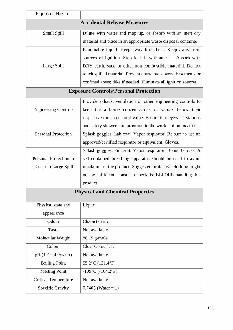
161
Explosion Hazards
Accidental Release Measures
Small Spill Dilute with water and mop up, or absorb with an inert dry
material and place in an appropriate waste disposal container
Large Spill
Flammable liquid. Keep away from heat. Keep away from
sources of ignition. Stop leak if without risk. Absorb with
DRY earth, sand or other non-combustible material. Do not
touch spilled material. Prevent entry into sewers, basements or
confined areas; dike if needed. Eliminate all ignition sources.
Exposure Controls/Personal Protection
Engineering Controls
Provide exhaust ventilation or other engineering controls to
keep the airborne concentrations of vapors below their
respective threshold limit value. Ensure that eyewash stations
and safety showers are proximal to the work-station location.
Personal Protection Splash goggles. Lab coat. Vapor respirator. Be sure to use an
approved/certified respirator or equivalent. Gloves.
Personal Protection in
Case of a Large Spill
Splash goggles. Full suit. Vapor respirator. Boots. Gloves. A
self-contained breathing apparatus should be used to avoid
inhalation of the product. Suggested protective clothing might
not be sufficient; consult a specialist BEFORE handling this
product
Physical and Chemical Properties
Physical state and
appearance
Liquid
Odour Characteristic
Taste Not available
Molecular Weight 88.15 g/mole
Colour Clear Colourless
pH (1% soln/water) Not available.
Boiling Point 55.2°C (131.4°F)
Melting Point -109°C (-164.2°F)
Critical Temperature Not available
Specific Gravity 0.7405 (Water = 1)
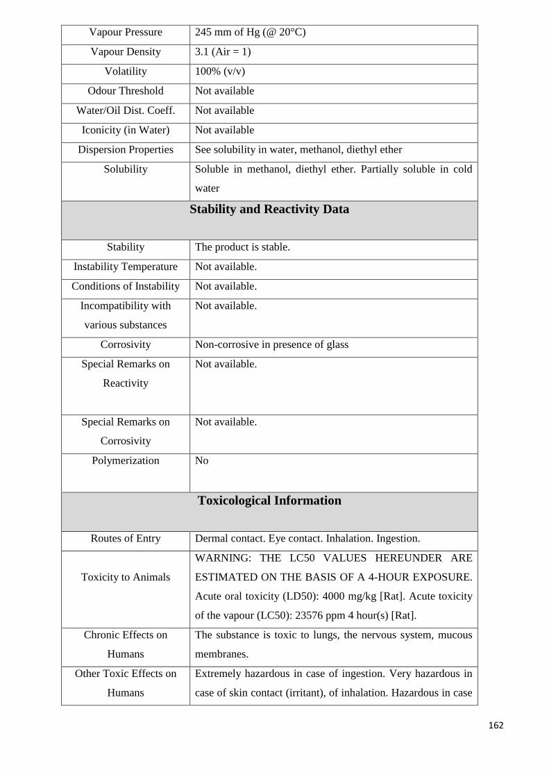
162
Vapour Pressure 245 mm of Hg (@ 20°C)
Vapour Density 3.1 (Air = 1)
Volatility 100% (v/v)
Odour Threshold Not available
Water/Oil Dist. Coeff. Not available
Iconicity (in Water) Not available
Dispersion Properties See solubility in water, methanol, diethyl ether
Solubility Soluble in methanol, diethyl ether. Partially soluble in cold
water
Stability and Reactivity Data
Stability The product is stable.
Instability Temperature Not available.
Conditions of Instability Not available.
Incompatibility with
various substances
Not available.
Corrosivity Non-corrosive in presence of glass
Special Remarks on
Reactivity
Not available.
Special Remarks on
Corrosivity
Not available.
Polymerization
No
Toxicological Information
Routes of Entry Dermal contact. Eye contact. Inhalation. Ingestion.
Toxicity to Animals
WARNING: THE LC50 VALUES HEREUNDER ARE
ESTIMATED ON THE BASIS OF A 4-HOUR EXPOSURE.
Acute oral toxicity (LD50): 4000 mg/kg [Rat]. Acute toxicity
of the vapour (LC50): 23576 ppm 4 hour(s) [Rat].
Chronic Effects on
Humans
The substance is toxic to lungs, the nervous system, mucous
membranes.
Other Toxic Effects on
Humans
Extremely hazardous in case of ingestion. Very hazardous in
case of skin contact (irritant), of inhalation. Hazardous in case
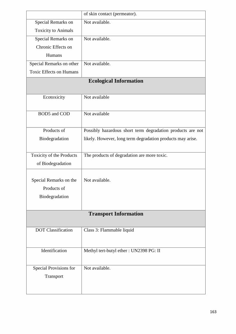
163
of skin contact (permeator).
Special Remarks on
Toxicity to Animals
Not available.
Special Remarks on
Chronic Effects on
Humans
Not available.
Special Remarks on other
Toxic Effects on Humans
Not available.
Ecological Information
Ecotoxicity Not available
BOD5 and COD Not available
Products of
Biodegradation
Possibly hazardous short term degradation products are not
likely. However, long term degradation products may arise.
Toxicity of the Products
of Biodegradation
The products of degradation are more toxic.
Special Remarks on the
Products of
Biodegradation
Not available.
Transport Information
DOT Classification Class 3: Flammable liquid
Identification Methyl tert-butyl ether : UN2398 PG: II
Special Provisions for
Transport
Not available.
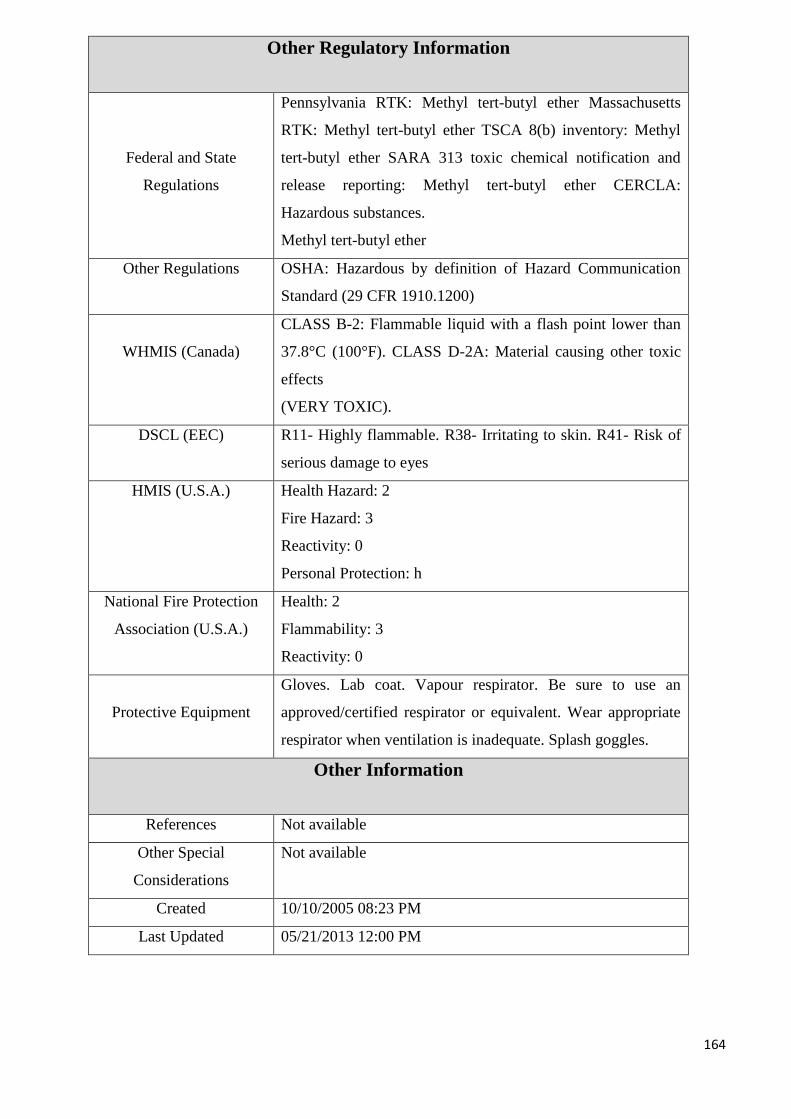
164
Other Regulatory Information
Federal and State
Regulations
Pennsylvania RTK: Methyl tert-butyl ether Massachusetts
RTK: Methyl tert-butyl ether TSCA 8(b) inventory: Methyl
tert-butyl ether SARA 313 toxic chemical notification and
release reporting: Methyl tert-butyl ether CERCLA:
Hazardous substances.
Methyl tert-butyl ether
Other Regulations OSHA: Hazardous by definition of Hazard Communication
Standard (29 CFR 1910.1200)
WHMIS (Canada)
CLASS B-2: Flammable liquid with a flash point lower than
37.8°C (100°F). CLASS D-2A: Material causing other toxic
effects
(VERY TOXIC).
DSCL (EEC) R11- Highly flammable. R38- Irritating to skin. R41- Risk of
serious damage to eyes
HMIS (U.S.A.) Health Hazard: 2
Fire Hazard: 3
Reactivity: 0
Personal Protection: h
National Fire Protection
Association (U.S.A.)
Health: 2
Flammability: 3
Reactivity: 0
Protective Equipment
Gloves. Lab coat. Vapour respirator. Be sure to use an
approved/certified respirator or equivalent. Wear appropriate
respirator when ventilation is inadequate. Splash goggles.
Other Information
References Not available
Other Special
Considerations
Not available
Created 10/10/2005 08:23 PM
Last Updated 05/21/2013 12:00 PM
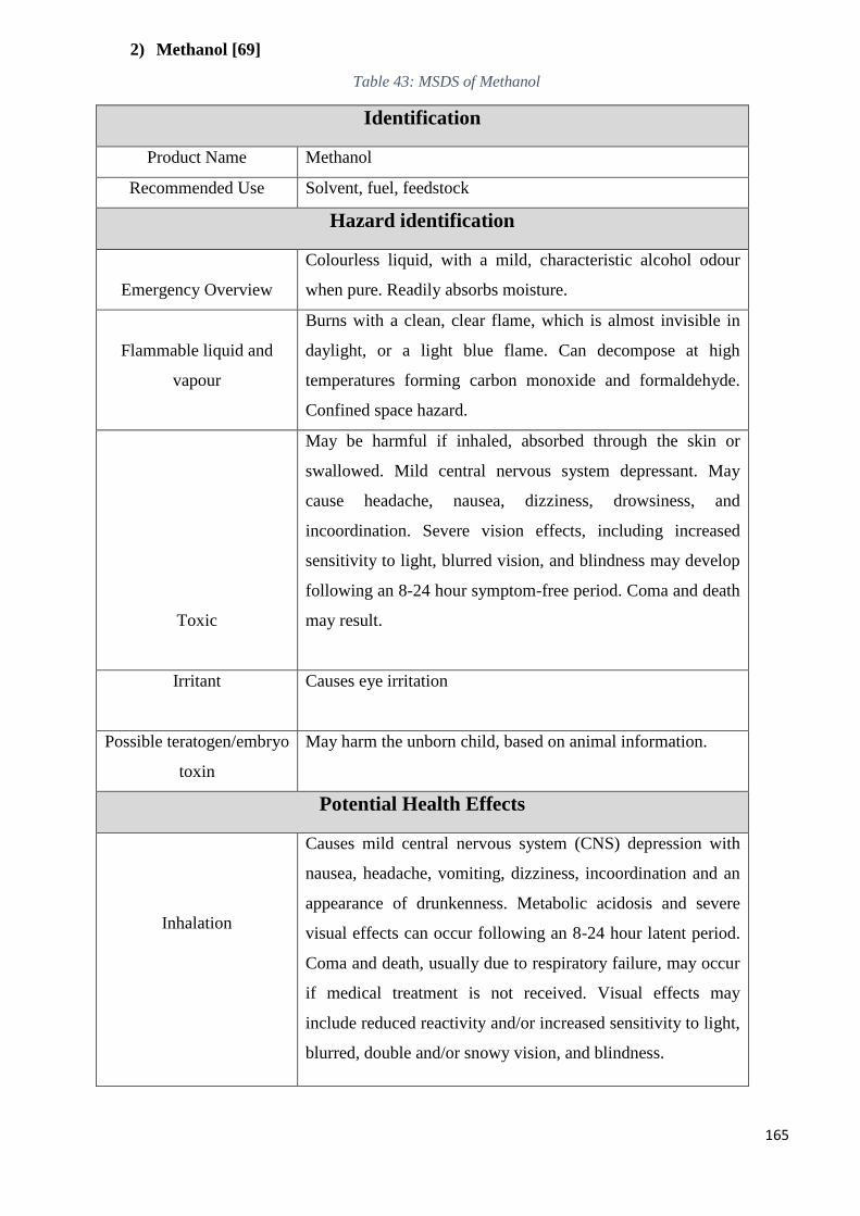
165
2) Methanol [69]
Table 43: MSDS of Methanol
Identification
Product Name Methanol
Recommended Use Solvent, fuel, feedstock
Hazard identification
Emergency Overview
Colourless liquid, with a mild, characteristic alcohol odour
when pure. Readily absorbs moisture.
Flammable liquid and
vapour
Burns with a clean, clear flame, which is almost invisible in
daylight, or a light blue flame. Can decompose at high
temperatures forming carbon monoxide and formaldehyde.
Confined space hazard.
Toxic
May be harmful if inhaled, absorbed through the skin or
swallowed. Mild central nervous system depressant. May
cause headache, nausea, dizziness, drowsiness, and
incoordination. Severe vision effects, including increased
sensitivity to light, blurred vision, and blindness may develop
following an 8-24 hour symptom-free period. Coma and death
may result.
Irritant Causes eye irritation
Possible teratogen/embryo
toxin
May harm the unborn child, based on animal information.
Potential Health Effects
Inhalation
Causes mild central nervous system (CNS) depression with
nausea, headache, vomiting, dizziness, incoordination and an
appearance of drunkenness. Metabolic acidosis and severe
visual effects can occur following an 8-24 hour latent period.
Coma and death, usually due to respiratory failure, may occur
if medical treatment is not received. Visual effects may
include reduced reactivity and/or increased sensitivity to light,
blurred, double and/or snowy vision, and blindness.
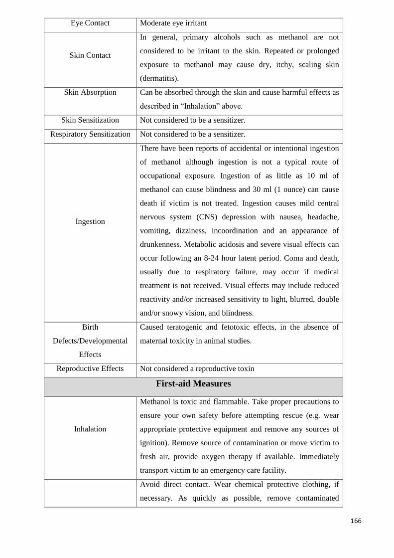
166
Eye Contact Moderate eye irritant
Skin Contact
In general, primary alcohols such as methanol are not
considered to be irritant to the skin. Repeated or prolonged
exposure to methanol may cause dry, itchy, scaling skin
(dermatitis).
Skin Absorption Can be absorbed through the skin and cause harmful effects as
described in “Inhalation” above.
Skin Sensitization Not considered to be a sensitizer.
Respiratory Sensitization Not considered to be a sensitizer.
Ingestion
There have been reports of accidental or intentional ingestion
of methanol although ingestion is not a typical route of
occupational exposure. Ingestion of as little as 10 ml of
methanol can cause blindness and 30 ml (1 ounce) can cause
death if victim is not treated. Ingestion causes mild central
nervous system (CNS) depression with nausea, headache,
vomiting, dizziness, incoordination and an appearance of
drunkenness. Metabolic acidosis and severe visual effects can
occur following an 8-24 hour latent period. Coma and death,
usually due to respiratory failure, may occur if medical
treatment is not received. Visual effects may include reduced
reactivity and/or increased sensitivity to light, blurred, double
and/or snowy vision, and blindness.
Birth
Defects/Developmental
Effects
Caused teratogenic and fetotoxic effects, in the absence of
maternal toxicity in animal studies.
Reproductive Effects Not considered a reproductive toxin
First-aid Measures
Inhalation
Methanol is toxic and flammable. Take proper precautions to
ensure your own safety before attempting rescue (e.g. wear
appropriate protective equipment and remove any sources of
ignition). Remove source of contamination or move victim to
fresh air, provide oxygen therapy if available. Immediately
transport victim to an emergency care facility.
Avoid direct contact. Wear chemical protective clothing, if
necessary. As quickly as possible, remove contaminated
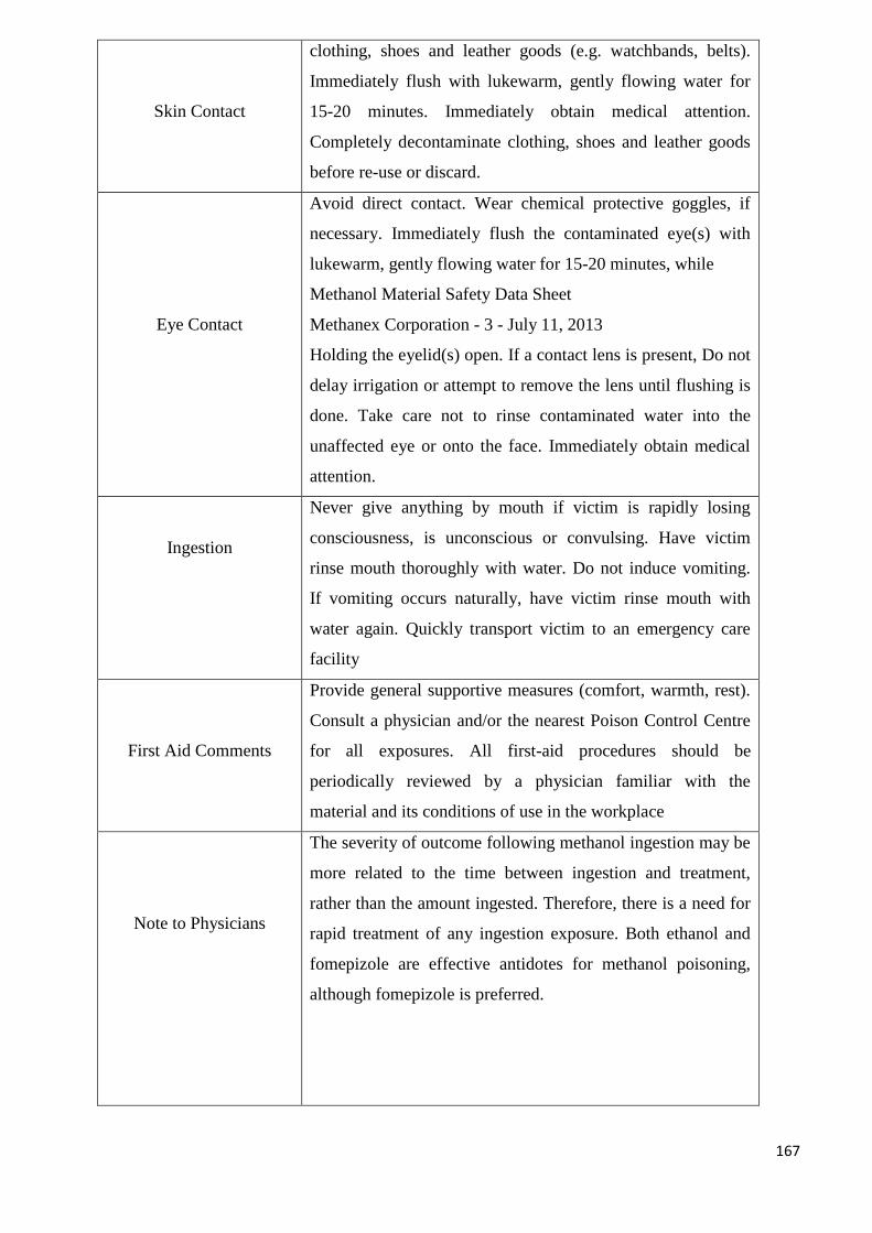
167
Skin Contact
clothing, shoes and leather goods (e.g. watchbands, belts).
Immediately flush with lukewarm, gently flowing water for
15-20 minutes. Immediately obtain medical attention.
Completely decontaminate clothing, shoes and leather goods
before re-use or discard.
Eye Contact
Avoid direct contact. Wear chemical protective goggles, if
necessary. Immediately flush the contaminated eye(s) with
lukewarm, gently flowing water for 15-20 minutes, while
Methanol Material Safety Data Sheet
Methanex Corporation - 3 - July 11, 2013
Holding the eyelid(s) open. If a contact lens is present, Do not
delay irrigation or attempt to remove the lens until flushing is
done. Take care not to rinse contaminated water into the
unaffected eye or onto the face. Immediately obtain medical
attention.
Ingestion
Never give anything by mouth if victim is rapidly losing
consciousness, is unconscious or convulsing. Have victim
rinse mouth thoroughly with water. Do not induce vomiting.
If vomiting occurs naturally, have victim rinse mouth with
water again. Quickly transport victim to an emergency care
facility
First Aid Comments
Provide general supportive measures (comfort, warmth, rest).
Consult a physician and/or the nearest Poison Control Centre
for all exposures. All first-aid procedures should be
periodically reviewed by a physician familiar with the
material and its conditions of use in the workplace
Note to Physicians
The severity of outcome following methanol ingestion may be
more related to the time between ingestion and treatment,
rather than the amount ingested. Therefore, there is a need for
rapid treatment of any ingestion exposure. Both ethanol and
fomepizole are effective antidotes for methanol poisoning,
although fomepizole is preferred.
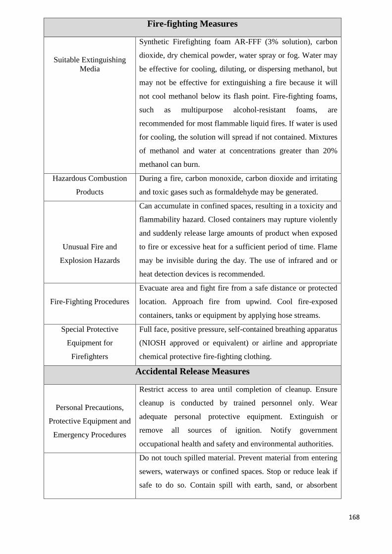
168
Fire-fighting Measures
Suitable Extinguishing
Media
Synthetic Firefighting foam AR-FFF (3% solution), carbon
dioxide, dry chemical powder, water spray or fog. Water may
be effective for cooling, diluting, or dispersing methanol, but
may not be effective for extinguishing a fire because it will
not cool methanol below its flash point. Fire-fighting foams,
such as multipurpose alcohol-resistant foams, are
recommended for most flammable liquid fires. If water is used
for cooling, the solution will spread if not contained. Mixtures
of methanol and water at concentrations greater than 20%
methanol can burn.
Hazardous Combustion
Products
During a fire, carbon monoxide, carbon dioxide and irritating
and toxic gases such as formaldehyde may be generated.
Unusual Fire and
Explosion Hazards
Can accumulate in confined spaces, resulting in a toxicity and
flammability hazard. Closed containers may rupture violently
and suddenly release large amounts of product when exposed
to fire or excessive heat for a sufficient period of time. Flame
may be invisible during the day. The use of infrared and or
heat detection devices is recommended.
Fire-Fighting Procedures
Evacuate area and fight fire from a safe distance or protected
location. Approach fire from upwind. Cool fire-exposed
containers, tanks or equipment by applying hose streams.
Special Protective
Equipment for
Firefighters
Full face, positive pressure, self-contained breathing apparatus
(NIOSH approved or equivalent) or airline and appropriate
chemical protective fire-fighting clothing.
Accidental Release Measures
Personal Precautions,
Protective Equipment and
Emergency Procedures
Restrict access to area until completion of cleanup. Ensure
cleanup is conducted by trained personnel only. Wear
adequate personal protective equipment. Extinguish or
remove all sources of ignition. Notify government
occupational health and safety and environmental authorities.
Do not touch spilled material. Prevent material from entering
sewers, waterways or confined spaces. Stop or reduce leak if
safe to do so. Contain spill with earth, sand, or absorbent
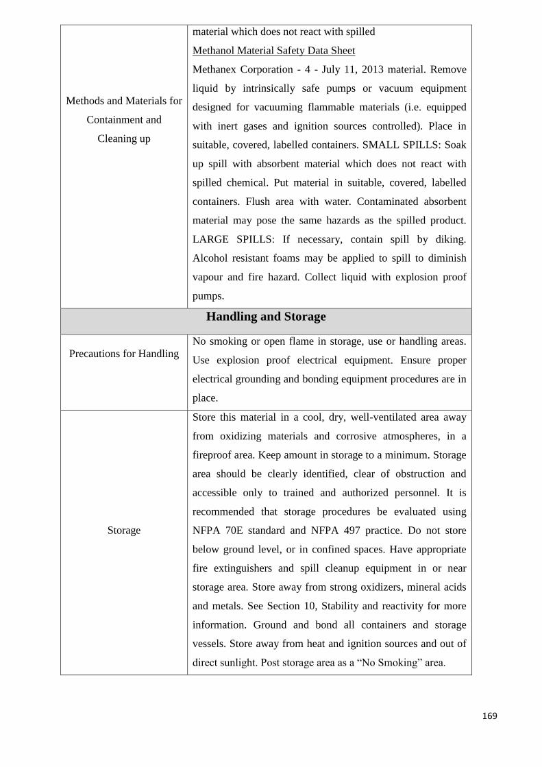
169
Methods and Materials for
Containment and
Cleaning up
material which does not react with spilled
Methanol Material Safety Data Sheet
Methanex Corporation - 4 - July 11, 2013 material. Remove
liquid by intrinsically safe pumps or vacuum equipment
designed for vacuuming flammable materials (i.e. equipped
with inert gases and ignition sources controlled). Place in
suitable, covered, labelled containers. SMALL SPILLS: Soak
up spill with absorbent material which does not react with
spilled chemical. Put material in suitable, covered, labelled
containers. Flush area with water. Contaminated absorbent
material may pose the same hazards as the spilled product.
LARGE SPILLS: If necessary, contain spill by diking.
Alcohol resistant foams may be applied to spill to diminish
vapour and fire hazard. Collect liquid with explosion proof
pumps.
Handling and Storage
Precautions for Handling
No smoking or open flame in storage, use or handling areas.
Use explosion proof electrical equipment. Ensure proper
electrical grounding and bonding equipment procedures are in
place.
Storage
Store this material in a cool, dry, well-ventilated area away
from oxidizing materials and corrosive atmospheres, in a
fireproof area. Keep amount in storage to a minimum. Storage
area should be clearly identified, clear of obstruction and
accessible only to trained and authorized personnel. It is
recommended that storage procedures be evaluated using
NFPA 70E standard and NFPA 497 practice. Do not store
below ground level, or in confined spaces. Have appropriate
fire extinguishers and spill cleanup equipment in or near
storage area. Store away from strong oxidizers, mineral acids
and metals. See Section 10, Stability and reactivity for more
information. Ground and bond all containers and storage
vessels. Store away from heat and ignition sources and out of
direct sunlight. Post storage area as a “No Smoking” area.
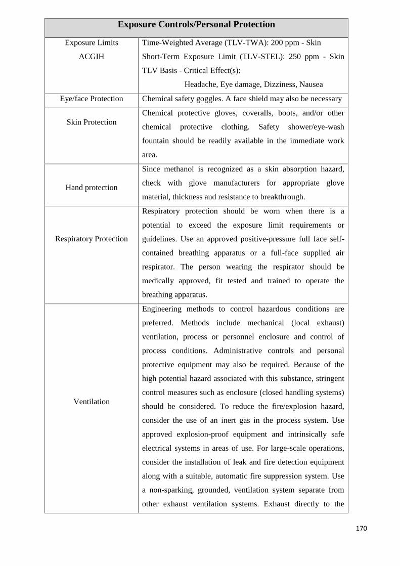
170
Exposure Controls/Personal Protection
Exposure Limits
ACGIH
Time-Weighted Average (TLV-TWA): 200 ppm - Skin
Short-Term Exposure Limit (TLV-STEL): 250 ppm - Skin
TLV Basis - Critical Effect(s):
Headache, Eye damage, Dizziness, Nausea
Eye/face Protection Chemical safety goggles. A face shield may also be necessary
Skin Protection
Chemical protective gloves, coveralls, boots, and/or other
chemical protective clothing. Safety shower/eye-wash
fountain should be readily available in the immediate work
area.
Hand protection
Since methanol is recognized as a skin absorption hazard,
check with glove manufacturers for appropriate glove
material, thickness and resistance to breakthrough.
Respiratory Protection
Respiratory protection should be worn when there is a
potential to exceed the exposure limit requirements or
guidelines. Use an approved positive-pressure full face self-
contained breathing apparatus or a full-face supplied air
respirator. The person wearing the respirator should be
medically approved, fit tested and trained to operate the
breathing apparatus.
Ventilation
Engineering methods to control hazardous conditions are
preferred. Methods include mechanical (local exhaust)
ventilation, process or personnel enclosure and control of
process conditions. Administrative controls and personal
protective equipment may also be required. Because of the
high potential hazard associated with this substance, stringent
control measures such as enclosure (closed handling systems)
should be considered. To reduce the fire/explosion hazard,
consider the use of an inert gas in the process system. Use
approved explosion-proof equipment and intrinsically safe
electrical systems in areas of use. For large-scale operations,
consider the installation of leak and fire detection equipment
along with a suitable, automatic fire suppression system. Use
a non-sparking, grounded, ventilation system separate from
other exhaust ventilation systems. Exhaust directly to the
171
outside. Supply sufficient replacement air to make up for air
removed by exhaust system.
Physical and Chemical Properties
Appearance Liquid, clear, colourless
Odour Mild characteristic alcohol odour
Odour Threshold
detection: 4.2 - 5960 ppm
(geometric mean) 160 ppm
recognition: 53 – 8940 ppm
(geometric mean) 690 ppm
pH Not applicable
Freezing Point 97.8°C
Boiling Point 64.7°C
Boiling Range Not determined
Flash Point 11.0oC
Solubility Completely soluble
Partial Coefficient Log P (oct) = -0.82
Vapour Pressure 12.8 kPa @ 20°C
Viscosity 0.3 cP@ 25°C
Upper Explosive Limit
(UEL)
36.5 %
Lower Explosive Limit
(LEL)
6%
Auto Ignition
Temperature
464°C
Solvent Solubility
Soluble in all proportions in ethanol, benzene, other alcohols,
chloroform, diethyl ether, other ethers, esters, ketones and
most organic solvents
Critical Temperature 239.4°C
Specific Gravity 0.791-0.793 @ 20°C
Evaporation Rate 4.1 (n-butyl acetate =1)
Vapour Density 1.105 @ 15°C (air = 1)
Decomposition
Temperature
Not determined
Sensitivity to Impact No
172
Sensitivity to Static
Charge
Low
Percent Volatility 100
Stability and Reactivity
Chemical Stability Stable as supplied.
Possibility of Hazardous
Reactions
Polymerization will not occur.
Conditions to Avoid
Heat, open flames, static discharge, sparks and other ignition
sources.
Incompatible Materials
Avoid contact with strong oxidizers, strong mineral or organic
acids, and strong bases. Contact with these materials may
cause a violent or explosive reaction. Methanol is not
compatible with gasket and O-rings materials made of Buna-
N and Nitrile. Methanol is corrosive to type 12L14 carbon
steel at room temperature and type 3003 aluminium, copper
(10-100% methanol solution) and admiralty brass, at 93 deg
C. Methanol is not corrosive to most metals. Methanol
attacks some forms of plastic, rubber and coatings.
Hazardous Decomposition
Products
Decomposes on heating to produce carbon monoxide and
formaldehyde.
Toxicological Information
Ingestion LD50 (oral, rat): 5600 mg/kg
LD50 (oral, rabbit): 14200 mg/kg
Dermal LD50 (dermal, rabbit): 15800 mg/kg
Inhalation
LC50 (rabbit): 81000 mg/m3/14h
LC50 (rat): 64000 ppm/4h
Eye Damage/Irritation Moderate eye irritant.
Skin Corrosion/Irritation Not considered to be an irritant.
Sensitization Not considered to be a sensitizer
Repeated Dose Toxicity No relevant data found
Chronic Toxicity and Not listed by IARC, NTP, ACGIH OR OSHA as a carcinogen
173
Carcinogenicity
Teratogenicity,
Embryotoxicity and/or
Fetotoxicity
Methanol has produced fetotoxicity in rats and teratogenicity
in mice exposed by inhalation to high concentrations that did
not produce significant maternal toxicity
Reproductive Toxicity Not considered to be a reproductive toxin.
Mutagenicity There is insufficient information available to conclude that
methanol is mutagenic.
Ecological Information
Persistence and
degradability
Readily biodegradable
Bioaccumulation Does not bioaccumulation. Partition coefficient: n-
octanol/water 0.77
Mobility in Soil Mobile in soils
PBT/vPvB
This substance is not considered to be persistent, bio
accumulating nor toxic (PBT). This substance is not
considered to be very persistent nor very bio accumulating
(vPvB).
Terrestrial Fate
The mobility of methanol in the subsurface will not be
significantly limited by adsorption. Sorption of methanol to
organic carbon in soil will be minor, and methanol will tend to
remain in soil pore water.
Aquatic Fate
Methanol is completely miscible with water. Accordingly, its
mobility in the subsurface will not be limited by solubility.
Methanol has been shown to undergo rapid biodegradation in
a variety of screening studies using sewage seed and activated
sludge inoculum, which suggests that biodegradation will
occur in aquatic environments where the concentration does
not inhibit bacterial activity
Atmospheric Fate
Methanol has a vapour pressure of 127 mm Hg at 25°C and is
expected to exist solely as a vapour in the ambient
atmosphere. Vapour-phase methanol is degraded in the
174
atmosphere by reaction with photo chemically-produced
hydroxyl radicals; the half-life for this reaction in air is
estimated to be 17 days.
Other Adverse Effects Do not flush into surface water or sanitary sewer system.
Disposal Considerations
Handling and storage
Disposal by controlled incineration or by secure land fill may
be acceptable. Recycle wherever possible. Large volumes
may be suitable for re-distillation or, if contaminated,
incineration. Can be disposed of in a sewage treatment
facility. Methanol levels of up to 0.1% act as a food source for
bacteria; above this level may be toxic to bacteria. When
pumping through sewage collection systems, the level of
methanol should be kept below the flammable range (a 25%
methanol/water mixture is non-flammable at temperatures
below 39°C). 1 ppm of methanol is equivalent to 1.5 ppm
BOD loading in the sewage plant.
Container disposal
Empty containers may contain hazardous residue. Return to
supplier for reuse if possible. Never weld, cut or grind empty
containers. If disposing of containers, ensure they are well
rinsed with water, then disposed of at an authorized landfill.
After cleaning, all existing labels should be removed.
Regulatory Information (Canadian Federal Regulations)
Hazardous Products Act
Information: CPR
Compliance
This product has been classified in accordance with the hazard
criteria of the Canadian Controlled Products Regulations
(CPR) and the MSDS contains all the information required by
the CPR
WHMIS Classification
B2 - Flammable and combustible material - Flammable liquid
D1B - Poisonous and infectious material - Immediate and
serious effects - Toxic D2A - Poisonous and infectious
material - Other effects - Very toxic D2B - Poisonous and
infectious material - Other effects - Toxic
175
CEPA, Domestic
Substances List
Methanol is listed on the Domestic Substances List.
WHMIS Ingredient
Disclosure List
Listed at 1%
Other Information
References SAX, N.I. Dangerous Properties of Indutrial Materials.
Toronto, Van Nostrand Reinold, 6e ed. 1984. -Material safety
Data sheet emitted by: la Commission de la Santé et de la
Sécurité du Travail du Québec. -Hawley, G.G... The
Condensed Chemical Dictionary, 11e ed., New York N.Y.,
Van Nostrand Reinold, 1987. LOLI, HSDB, RTECS,
HAZARDTEXT,
REPROTOX databases
Other Special
Considerations
Not available
Created 10/10/2005 08:23 PM
Last Updated 05/21/2013 12:00 PM
3) Isobutylene [70]
Table 44: MSDS of Isobutylene
Identification
Name Isobutylene
Formula C4H8 / CH2=C(CH3)2
Other means of
identification
Isobutene
Hazards Identification
Signal word (GHS-US) DANGER
Hazard statements (GHS-
US)
H220 - EXTREMELY FLAMMABLE GAS
H280 - CONTAINS GAS UNDER PRESSURE; MAY
EXPLODE IF HEATED
OSHA-H01 - MAY DISPLACE OXYGEN AND CAUSE
RAPID SUFFOCATION.
176
CGA-HG04 - MAY FORM EXPLOSIVE MIXTURES WITH
AIR CGA-HG01 - MAY CAUSE FROSTBITE
Precautionary statements
(GHS-US)
P202 - Do not handle until all safety precautions have been
read and understood
P210 - Keep away from Heat, Open flames, Sparks, Hot
surfaces. - No smoking
P271+P403 - Use and store only outdoors or in a well-
ventilated place.
P377 - Leaking gas fire: Do not extinguish, unless leak can be
stopped safely
P381 - Eliminate all ignition sources if safe to do so
CGA-PG05 - Use a back flow preventive device in the piping.
CGA-PG12 - Do not open valve until connected to equipment
prepared for use.
CGA-PG06 - Close valve after each use and when empty.
CGA-PG11 - Never put cylinders into unventilated areas of
passenger vehicles.
CGA-PG02 - Protect from sunlight when ambient temperature
exceeds 52°C (125°F).
First Aid Measures
First-aid measures after
inhalation
Immediately remove to fresh air. If not breathing, give
artificial respiration. If breathing is difficult, qualified
personnel may give oxygen. Call a physician.
First-aid measures after
skin contact
For exposure to liquid, immediately warm frostbite area with
warm water not to exceed 105°F (41°C). Water temperature
should be tolerable to normal skin. Maintain skin warming for
at least 15 minutes or until normal colouring and sensation
have returned to the affected area. In case of massive
exposure, remove clothing while showering with warm water.
Seek medical evaluation and treatment as soon as possible
First-aid measures after
eye contact
Immediately flush eyes thoroughly with water for at least 15
minutes. Hold the eyelids open and away from the eyeballs to
ensure that all surfaces are flushed thoroughly. Contact an
ophthalmologist immediately.
177
First-aid measures after
ingestion
Ingestion is not considered a potential route of exposure.
Firefighting measures
Suitable extinguishing
media
Carbon dioxide, Dry chemical, Water spray or fog.
Fire hazard
EXTREMELY FLAMMABLE GAS. If venting or leaking
gas catches fire, do not extinguish flames. Flammable vapors
may spread from leak, creating an explosive reignition hazard.
Vapors can be ignited by pilot lights, other flames, smoking,
sparks, heaters, electrical equipment, static discharge, or other
ignition sources at locations distant from product handling
point. Explosive atmospheres may linger. Before entering an
area, especially a confined area, check the atmosphere with an
appropriate device.
Explosion hazard EXTREMELY FLAMMABLE GAS. Forms explosive
mixtures with air and oxidizing agents.
Reactivity No reactivity hazard other than the effects described in sub-
sections below.
Firefighting instructions
DANGER: FLAMMABLE LIQUID AND VAPOR. Evacuate
all personnel from danger area. Use self-contained breathing
apparatus. Immediately cool surrounding containers with
water spray from maximum distance, taking care not to
extinguish flames. Avoid spreading burning liquid with water.
Remove ignition sources if safe to do so. If flames are
accidentally extinguished, explosive reigniting may occur.
Reduce vapors with water spray or fog. Stop flow of liquid if
safe to do so, while continuing cooling water spray. Remove
all containers from area of fire if safe to do so. Allow fire to
burn out. On-site fire brigades must comply with OSHA 29
CFR 1910.156 and applicable standards under 29 CFR 1919
Subpart L - Fire Protection
Special protective
equipment for fire fighters
Standard protective clothing and equipment (Self Contained
Breathing Apparatus) for fire fighters
Other information Containers are equipped with a pressure relief device.
178
(Exceptions may exist where authorized by DOT.).
Accidental Release Measures
General measures
DANGER: Flammable liquid and gas under pressure. Forms
explosive mixtures with air. Immediately evacuate all
personnel from danger area. Use self-contained breathing
apparatus where needed. Remove all sources of ignition if
safe to do so. Reduce vapors with fog or fine water spray,
taking care not to spread liquid with water. Shut off flow if
safe to do so. Ventilate area or move container to a well-
ventilated area. Flammable vapors may spread from leak and
could explode if reignited by sparks or flames. Explosive
atmospheres may linger. Before entering area, especially
confined areas, check atmosphere with an appropriate device.
Handling and storage
Precautions for safe
handling
Keep away from heat, hot surfaces, sparks, open flames and
other ignition sources. No smoking. Use only non-sparking
tools. Use only explosion-proof equipment. Wear leather
safety gloves and safety shoes when handling cylinders.
Protect cylinders from physical damage; do not drag, roll,
slide or drop. While moving cylinder, always keep in place
removable valve cover. Never attempt to lift a cylinder by its
cap; the cap is intended solely to protect the valve. When
moving cylinders, even for short distances, use a cart (trolley,
hand truck, etc.) designed to transport cylinders. Never insert
an object (e.g., wrench, screwdriver, and pry bar) into cap
openings; doing so may damage the valve and cause a leak.
Use an adjustable strap wrench to remove over-tight or rusted
caps. Slowly open the valve. If the valve is hard to open,
discontinue use and contact your supplier. Close the container
valve after each use; keep closed even when empty. Never
apply flame or localized heat directly to any part of the
container. High temperatures may damage the container and
could cause the pressure relief device to fail prematurely,
venting the container contents. For other precautions in using
179
this product, see section 16.
Storage conditions
Store only where temperature will not exceed 125°F (52°C).
Post “No Smoking or Open Flames” signs in storage and use
areas. There must be no sources of ignition. Separate
packages and protect against potential fire and/or explosion
damage following appropriate codes and requirements (e.g.,
NFPA 30, NFPA 55, NFPA 70, and/or NFPA 221 in the U.S.)
or according to requirements determined by the Authority
Having Jurisdiction (AHJ). Always secure containers upright
to keep them from falling or being knocked over. Install valve
protection cap, if provided, firmly in place by hand when the
container is not in use. Store full and empty containers
separately. Use a first-in, first-out inventory system to prevent
storing full containers for long periods. For other precautions
in using this product, see section 16. OTHER
PRECAUTIONS FOR HANDLING, STORAGE, and USE:
When handling product under pressure, use piping and
equipment adequately designed to withstand the pressures to
be encountered. Never work on a pressurized system. Use a
back flow preventive device in the piping. Gases can cause
rapid suffocation because of oxygen deficiency; store and use
with adequate ventilation. If a leak occurs, close the container
valve and blow down the system in a safe and
environmentally correct manner in compliance with all
international, federal/national, state/provincial, and local laws;
and then repair the leak. Never place a container where it may
become part of an electrical circuit.
Exposure controls/personal protection
Appropriate engineering
controls
Use an explosion-proof local exhaust system. Local exhaust
and general ventilation must be adequate to meet exposure
standards. MECHANICAL (GENERAL): Inadequate - Use
only in a closed system. Use explosion proof equipment and
lighting.
Eye protection
: Wear safety glasses when handling cylinders; vapor-proof
goggles and a face shield during cylinder change out or
180
whenever contact with product is possible. Select eye
protection in accordance with OSHA 29 CFR 1910.133.
Skin and body protection
Wear metatarsal shoes and work gloves for cylinder handling,
and protective clothing where needed. Wear neoprene gloves
during cylinder change out or wherever contact with product
is possible. Select per OSHA 29 CFR 1910.132, 1910.136,
and 1910.138.
Respiratory protection
When workplace conditions warrant respirator use, follow a
respiratory protection program that meets OSHA 29 CFR
1910.134, ANSI Z88.2, or MSHA 30 CFR 72.710 (where
applicable). Use an air-supplied or air-purifying cartridge if
the action level is exceeded. Ensure that the respirator has the
appropriate protection factor for the exposure level. If
cartridge type respirators are used, the cartridge must be
appropriate for the chemical exposure (e.g., an organic vapor
cartridge). For emergencies or instances with unknown
exposure levels, use a self-contained breathing apparatus
(SCBA).
Thermal hazard protection Wear cold insulating gloves when trans filling or breaking
transfer connections.
Physical and chemical properties
Physical state Gas
Molecular mass 56 g/mol
Colour colourless
Odour Sweetish
Odour threshold Odour threshold is subjective and inadequate to warn for
overexposure
pH
Not applicable
Relative evaporation rate
(butyl acetate=1)
No data available
Relative evaporation rate
(ether=1)
Not applicable
181
Melting point 140.3 °C
Freezing point No data available
Boiling point -6.9 °C
Flash point -80 °C (closed cup)
Critical temperature 144 °C
Auto-ignition
temperature
465 °C
Decomposition
temperature
No data available
Flammability (solid, gas) 1.8 - 8.8 vol %
Vapour pressure 260 kPa
Critical pressure 4000 kPa
Relative vapor density at
20 °C
No data available
Specific gravity / density 0.599 g/cm³ (at 20 °C)
Relative gas density 2
Solubility Water: 388 mg/l
Log Pow 2.35
Log Kow Not applicable
Viscosity, kinematic Not applicable
Viscosity, dynamic Not applicable
Explosive properties Not applicable
Oxidizing properties None
Explosive limits No data available
Gas group Liquefied gas
Additional information Gas/vapour heavier than air. May accumulate in confined
spaces, particularly at or below ground level.
Stability and Reactivity
Reactivity No reactivity hazard other than the effects described in sub-
sections below
Chemical stability Stable under normal conditions
Possibility of hazardous
reactions
May occur
Conditions to avoid High temperature. Catalyst.
182
Incompatible materials Halogens. Oxidizing agents. Acids.
Hazardous decomposition
products
Thermal decomposition may produce: Carbon monoxide.
Carbon dioxide.
Toxicological information
Acute toxicity Not classified
Isobutylene ( \f )115-11-7
LC50 inhalation rat (mg/l) 620 mg/l/4h
LC50 inhalation rat (ppm) ≥ 10000
ATE US (gases) 10000.000 ppm V/4h
ATE US (vapors) 620.000 mg/l/4h
ATE US (dust, mist) 620.000 mg/l/4h
Skin corrosion/irritation Not classified
Serious eye
damage/irritation
Not classified
pH Not applicable
Respiratory or skin
sensitization
Not classified
Germ cell mutagenicity Not classified
Carcinogenicity Not classified
Reproductive toxicity Not classified
Specific target organ
toxicity (single exposure)
Not classified
Specific target organ
toxicity (repeated
exposure
Not classified
Aspiration hazard Not classified
Ecological information
Ecology
general
No known ecological damage caused by this product.
Persistence and
degradability
Isobutylene (115-11-7)
Persistence and degradability The substance is biodegradable.
Bio accumulative
potential
Isobutylene (115-11-7)
Log Pow = 2.35
Log Kow = Not applicable.
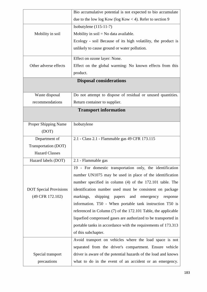
183
Bio accumulative potential is not expected to bio accumulate
due to the low log Kow (log Kow < 4). Refer to section 9
Mobility in soil
Isobutylene (115-11-7)
Mobility in soil = No data available.
Ecology - soil Because of its high volatility, the product is
unlikely to cause ground or water pollution.
Other adverse effects
Effect on ozone layer: None.
Effect on the global warming: No known effects from this
product.
Disposal considerations
Waste disposal
recommendations
Do not attempt to dispose of residual or unused quantities.
Return container to supplier.
Transport information
Proper Shipping Name
(DOT)
Isobutylene
Department of
Transportation (DOT)
Hazard Classes
2.1 - Class 2.1 - Flammable gas 49 CFR 173.115
Hazard labels (DOT) 2.1 - Flammable gas
DOT Special Provisions
(49 CFR 172.102)
19 - For domestic transportation only, the identification
number UN1075 may be used in place of the identification
number specified in column (4) of the 172.101 table. The
identification number used must be consistent on package
markings, shipping papers and emergency response
information. T50 - When portable tank instruction T50 is
referenced in Column (7) of the 172.101 Table, the applicable
liquefied compressed gases are authorized to be transported in
portable tanks in accordance with the requirements of 173.313
of this subchapter.
Special transport
precautions
Avoid transport on vehicles where the load space is not
separated from the driver's compartment. Ensure vehicle
driver is aware of the potential hazards of the load and knows
what to do in the event of an accident or an emergency.
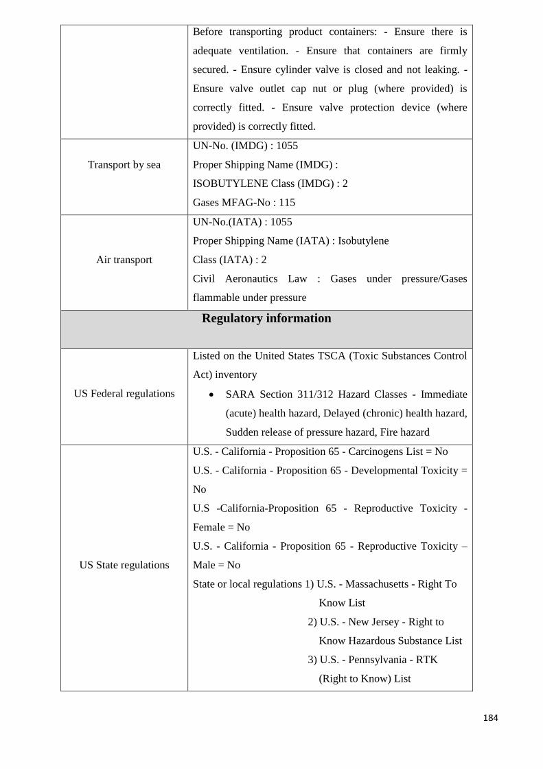
184
Before transporting product containers: - Ensure there is
adequate ventilation. - Ensure that containers are firmly
secured. - Ensure cylinder valve is closed and not leaking. -
Ensure valve outlet cap nut or plug (where provided) is
correctly fitted. - Ensure valve protection device (where
provided) is correctly fitted.
Transport by sea
UN-No. (IMDG) : 1055
Proper Shipping Name (IMDG) :
ISOBUTYLENE Class (IMDG) : 2
Gases MFAG-No : 115
Air transport
UN-No.(IATA) : 1055
Proper Shipping Name (IATA) : Isobutylene
Class (IATA) : 2
Civil Aeronautics Law : Gases under pressure/Gases
flammable under pressure
Regulatory information
US Federal regulations
Listed on the United States TSCA (Toxic Substances Control
Act) inventory
SARA Section 311/312 Hazard Classes - Immediate
(acute) health hazard, Delayed (chronic) health hazard,
Sudden release of pressure hazard, Fire hazard
US State regulations
U.S. - California - Proposition 65 - Carcinogens List = No
U.S. - California - Proposition 65 - Developmental Toxicity =
No
U.S -California-Proposition 65 - Reproductive Toxicity -
Female = No
U.S. - California - Proposition 65 - Reproductive Toxicity –
Male = No
State or local regulations 1) U.S. - Massachusetts - Right To
Know List
2) U.S. - New Jersey - Right to
Know Hazardous Substance List
3) U.S. - Pennsylvania - RTK
(Right to Know) List
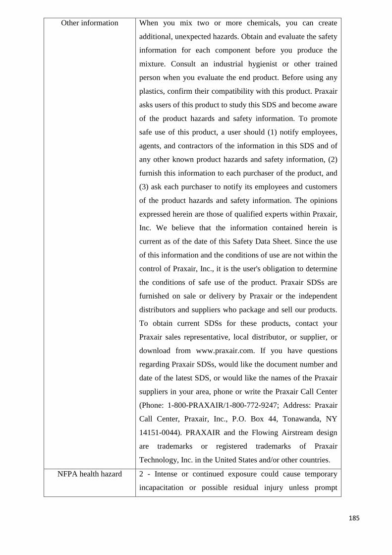
185
Other information When you mix two or more chemicals, you can create
additional, unexpected hazards. Obtain and evaluate the safety
information for each component before you produce the
mixture. Consult an industrial hygienist or other trained
person when you evaluate the end product. Before using any
plastics, confirm their compatibility with this product. Praxair
asks users of this product to study this SDS and become aware
of the product hazards and safety information. To promote
safe use of this product, a user should (1) notify employees,
agents, and contractors of the information in this SDS and of
any other known product hazards and safety information, (2)
furnish this information to each purchaser of the product, and
(3) ask each purchaser to notify its employees and customers
of the product hazards and safety information. The opinions
expressed herein are those of qualified experts within Praxair,
Inc. We believe that the information contained herein is
current as of the date of this Safety Data Sheet. Since the use
of this information and the conditions of use are not within the
control of Praxair, Inc., it is the user's obligation to determine
the conditions of safe use of the product. Praxair SDSs are
furnished on sale or delivery by Praxair or the independent
distributors and suppliers who package and sell our products.
To obtain current SDSs for these products, contact your
Praxair sales representative, local distributor, or supplier, or
download from www.praxair.com. If you have questions
regarding Praxair SDSs, would like the document number and
date of the latest SDS, or would like the names of the Praxair
suppliers in your area, phone or write the Praxair Call Center
(Phone: 1-800-PRAXAIR/1-800-772-9247; Address: Praxair
Call Center, Praxair, Inc., P.O. Box 44, Tonawanda, NY
14151-0044). PRAXAIR and the Flowing Airstream design
are trademarks or registered trademarks of Praxair
Technology, Inc. in the United States and/or other countries.
NFPA health hazard 2 - Intense or continued exposure could cause temporary
incapacitation or possible residual injury unless prompt
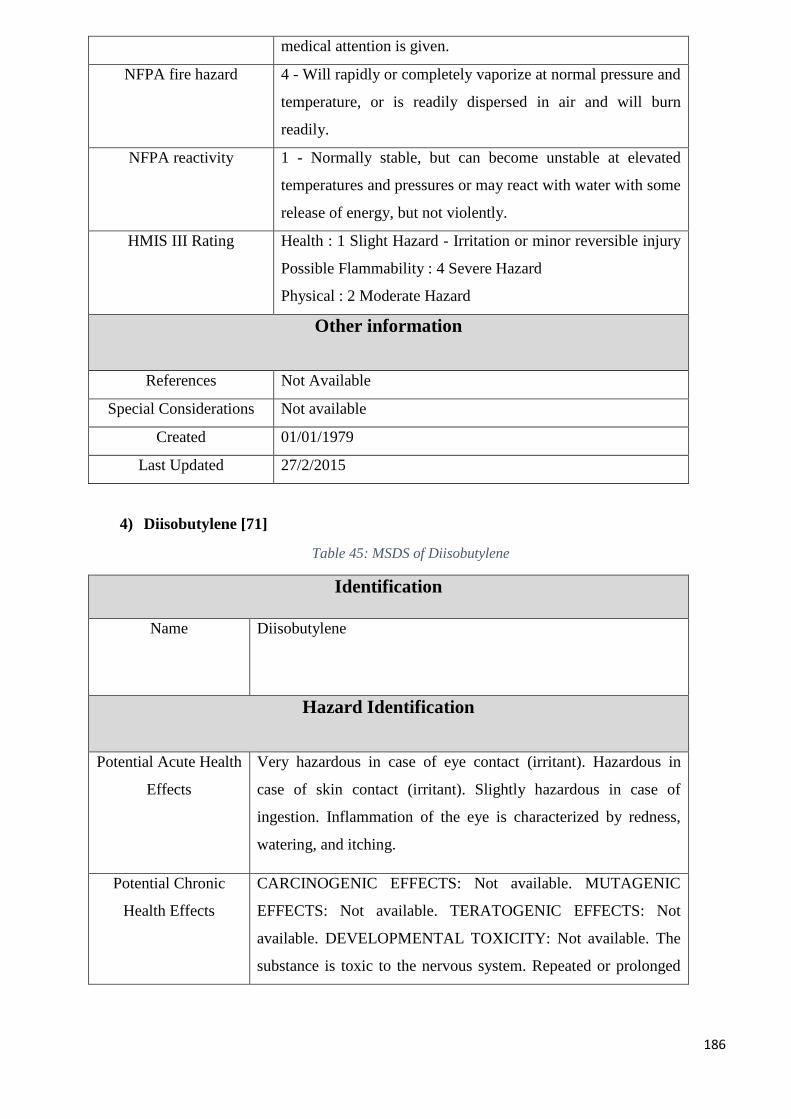
186
medical attention is given.
NFPA fire hazard 4 - Will rapidly or completely vaporize at normal pressure and
temperature, or is readily dispersed in air and will burn
readily.
NFPA reactivity 1 - Normally stable, but can become unstable at elevated
temperatures and pressures or may react with water with some
release of energy, but not violently.
HMIS III Rating Health : 1 Slight Hazard - Irritation or minor reversible injury
Possible Flammability : 4 Severe Hazard
Physical : 2 Moderate Hazard
Other information
References Not Available
Special Considerations Not available
Created 01/01/1979
Last Updated 27/2/2015
4) Diisobutylene [71]
Table 45: MSDS of Diisobutylene
Identification
Name Diisobutylene
Hazard Identification
Potential Acute Health
Effects
Very hazardous in case of eye contact (irritant). Hazardous in
case of skin contact (irritant). Slightly hazardous in case of
ingestion. Inflammation of the eye is characterized by redness,
watering, and itching.
Potential Chronic
Health Effects
CARCINOGENIC EFFECTS: Not available. MUTAGENIC
EFFECTS: Not available. TERATOGENIC EFFECTS: Not
available. DEVELOPMENTAL TOXICITY: Not available. The
substance is toxic to the nervous system. Repeated or prolonged
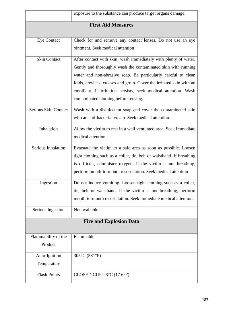
187
exposure to the substance can produce target organs damage.
First Aid Measures
Eye Contact Check for and remove any contact lenses. Do not use an eye
ointment. Seek medical attention
Skin Contact After contact with skin, wash immediately with plenty of water.
Gently and thoroughly wash the contaminated skin with running
water and non-abrasive soap. Be particularly careful to clean
folds, crevices, creases and groin. Cover the irritated skin with an
emollient. If irritation persists, seek medical attention. Wash
contaminated clothing before reusing.
Serious Skin Contact Wash with a disinfectant soap and cover the contaminated skin
with an anti-bacterial cream. Seek medical attention.
Inhalation Allow the victim to rest in a well ventilated area. Seek immediate
medical attention.
Serious Inhalation Evacuate the victim to a safe area as soon as possible. Loosen
tight clothing such as a collar, tie, belt or waistband. If breathing
is difficult, administer oxygen. If the victim is not breathing,
perform mouth-to-mouth resuscitation. Seek medical attention
Ingestion Do not induce vomiting. Loosen tight clothing such as a collar,
tie, belt or waistband. If the victim is not breathing, perform
mouth-to-mouth resuscitation. Seek immediate medical attention.
Serious Ingestion Not available.
Fire and Explosion Data
Flammability of the
Product
Flammable
Auto-Ignition
Temperature
305°C (581°F)
Flash Points CLOSED CUP: -8°C (17.6°F)
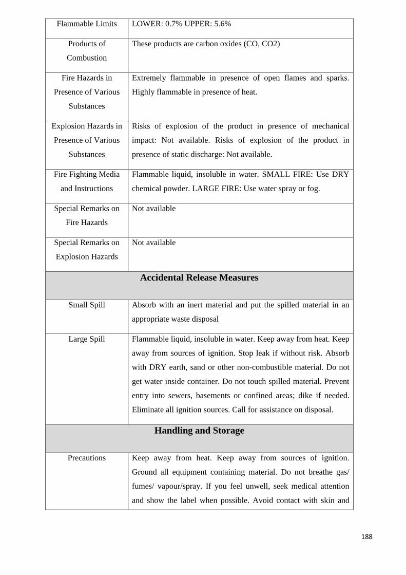
188
Flammable Limits LOWER: 0.7% UPPER: 5.6%
Products of
Combustion
These products are carbon oxides (CO, CO2)
Fire Hazards in
Presence of Various
Substances
Extremely flammable in presence of open flames and sparks.
Highly flammable in presence of heat.
Explosion Hazards in
Presence of Various
Substances
Risks of explosion of the product in presence of mechanical
impact: Not available. Risks of explosion of the product in
presence of static discharge: Not available.
Fire Fighting Media
and Instructions
Flammable liquid, insoluble in water. SMALL FIRE: Use DRY
chemical powder. LARGE FIRE: Use water spray or fog.
Special Remarks on
Fire Hazards
Not available
Special Remarks on
Explosion Hazards
Not available
Accidental Release Measures
Small Spill Absorb with an inert material and put the spilled material in an
appropriate waste disposal
Large Spill Flammable liquid, insoluble in water. Keep away from heat. Keep
away from sources of ignition. Stop leak if without risk. Absorb
with DRY earth, sand or other non-combustible material. Do not
get water inside container. Do not touch spilled material. Prevent
entry into sewers, basements or confined areas; dike if needed.
Eliminate all ignition sources. Call for assistance on disposal.
Handling and Storage
Precautions Keep away from heat. Keep away from sources of ignition.
Ground all equipment containing material. Do not breathe gas/
fumes/ vapour/spray. If you feel unwell, seek medical attention
and show the label when possible. Avoid contact with skin and
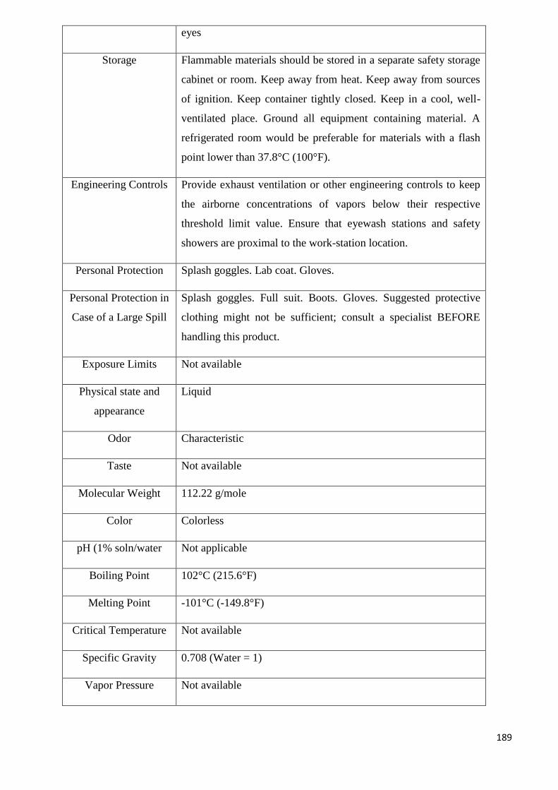
189
eyes
Storage Flammable materials should be stored in a separate safety storage
cabinet or room. Keep away from heat. Keep away from sources
of ignition. Keep container tightly closed. Keep in a cool, well-
ventilated place. Ground all equipment containing material. A
refrigerated room would be preferable for materials with a flash
point lower than 37.8°C (100°F).
Engineering Controls Provide exhaust ventilation or other engineering controls to keep
the airborne concentrations of vapors below their respective
threshold limit value. Ensure that eyewash stations and safety
showers are proximal to the work-station location.
Personal Protection Splash goggles. Lab coat. Gloves.
Personal Protection in
Case of a Large Spill
Splash goggles. Full suit. Boots. Gloves. Suggested protective
clothing might not be sufficient; consult a specialist BEFORE
handling this product.
Exposure Limits Not available
Physical state and
appearance
Liquid
Odor Characteristic
Taste Not available
Molecular Weight 112.22 g/mole
Color Colorless
pH (1% soln/water Not applicable
Boiling Point 102°C (215.6°F)
Melting Point -101°C (-149.8°F)
Critical Temperature Not available
Specific Gravity 0.708 (Water = 1)
Vapor Pressure Not available
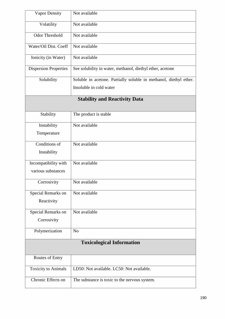
190
Vapor Density Not available
Volatility Not available
Odor Threshold Not available
Water/Oil Dist. Coeff Not available
Ionicity (in Water) Not available
Dispersion Properties See solubility in water, methanol, diethyl ether, acetone
Solubility Soluble in acetone. Partially soluble in methanol, diethyl ether.
Insoluble in cold water
Stability and Reactivity Data
Stability The product is stable
Instability
Temperature
Not available
Conditions of
Instability
Not available
Incompatibility with
various substances
Not available
Corrosivity Not available
Special Remarks on
Reactivity
Not available
Special Remarks on
Corrosivity
Not available
Polymerization No
Toxicological Information
Routes of Entry
Toxicity to Animals LD50: Not available. LC50: Not available.
Chronic Effects on The substance is toxic to the nervous system.
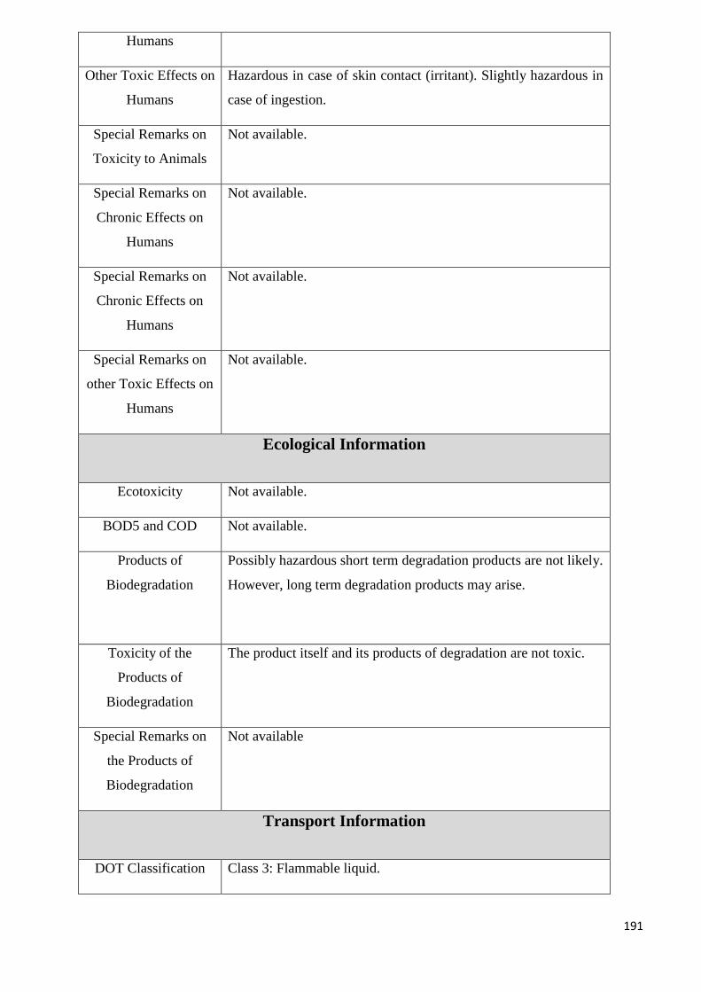
191
Humans
Other Toxic Effects on
Humans
Hazardous in case of skin contact (irritant). Slightly hazardous in
case of ingestion.
Special Remarks on
Toxicity to Animals
Not available.
Special Remarks on
Chronic Effects on
Humans
Not available.
Special Remarks on
Chronic Effects on
Humans
Not available.
Special Remarks on
other Toxic Effects on
Humans
Not available.
Ecological Information
Ecotoxicity Not available.
BOD5 and COD Not available.
Products of
Biodegradation
Possibly hazardous short term degradation products are not likely.
However, long term degradation products may arise.
Toxicity of the
Products of
Biodegradation
The product itself and its products of degradation are not toxic.
Special Remarks on
the Products of
Biodegradation
Not available
Transport Information
DOT Classification Class 3: Flammable liquid.
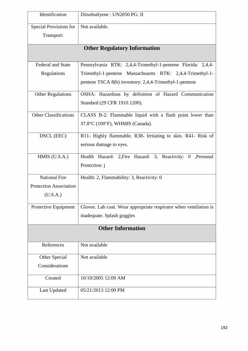
192
Identification Diisobutlyene : UN2050 PG: II
Special Provisions for
Transport:
Not available.
Other Regulatory Information
Federal and State
Regulations
Pennsylvania RTK: 2,4,4-Trimethyl-1-pentene Florida: 2,4,4-
Trimethyl-1-pentene Massachusetts RTK: 2,4,4-Trimethyl-1-
pentene TSCA 8(b) inventory: 2,4,4-Trimethyl-1-pentene
Other Regulations OSHA: Hazardous by definition of Hazard Communication
Standard (29 CFR 1910.1200).
Other Classifications CLASS B-2: Flammable liquid with a flash point lower than
37.8°C (100°F), WHMIS (Canada).
DSCL (EEC) R11- Highly flammable. R38- Irritating to skin. R41- Risk of
serious damage to eyes.
HMIS (U.S.A.) Health Hazard: 2,Fire Hazard: 3, Reactivity: 0 ,Personal
Protection: j
National Fire
Protection Association
(U.S.A.)
Health: 2, Flammability: 3, Reactivity: 0
Protective Equipment Gloves. Lab coat. Wear appropriate respirator when ventilation is
inadequate. Splash goggles
Other Information
References Not available
Other Special
Considerations
Not available
Created 10/10/2005 12:09 AM
Last Updated 05/21/2013 12:00 PM
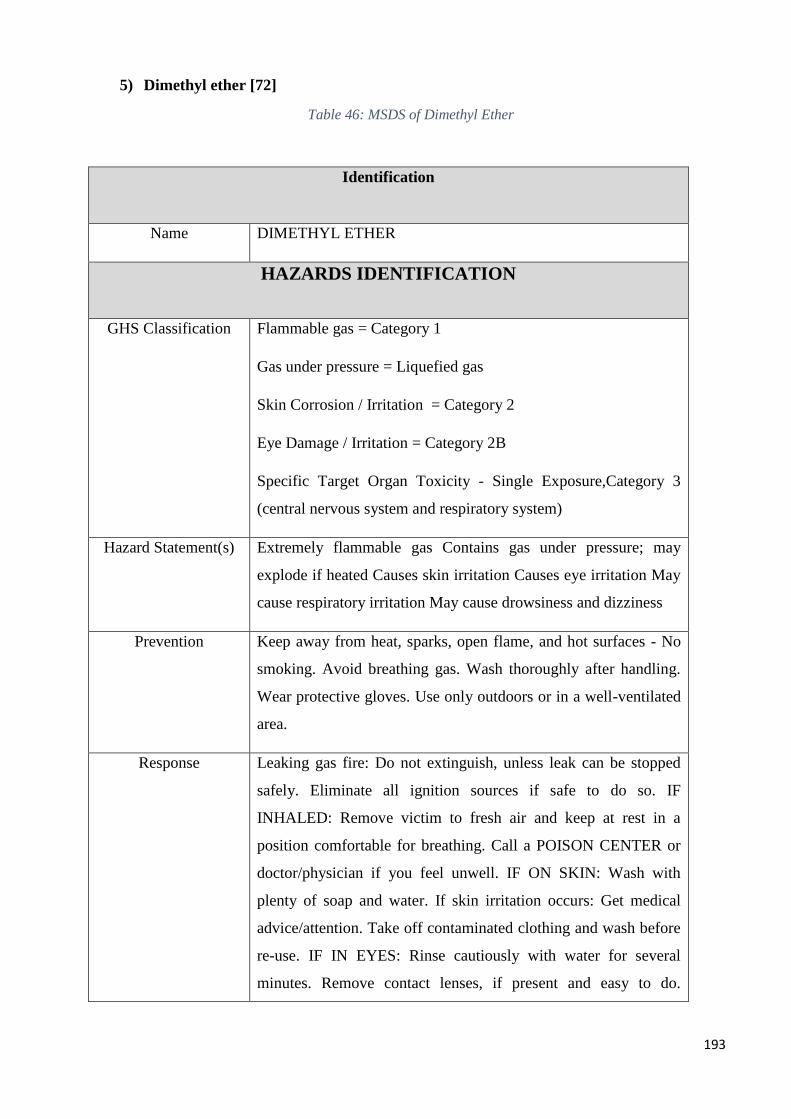
193
5) Dimethyl ether [72]
Table 46: MSDS of Dimethyl Ether
Identification
Name DIMETHYL ETHER
HAZARDS IDENTIFICATION
GHS Classification Flammable gas = Category 1
Gas under pressure = Liquefied gas
Skin Corrosion / Irritation = Category 2
Eye Damage / Irritation = Category 2B
Specific Target Organ Toxicity - Single Exposure,Category 3
(central nervous system and respiratory system)
Hazard Statement(s) Extremely flammable gas Contains gas under pressure; may
explode if heated Causes skin irritation Causes eye irritation May
cause respiratory irritation May cause drowsiness and dizziness
Prevention Keep away from heat, sparks, open flame, and hot surfaces - No
smoking. Avoid breathing gas. Wash thoroughly after handling.
Wear protective gloves. Use only outdoors or in a well-ventilated
area.
Response Leaking gas fire: Do not extinguish, unless leak can be stopped
safely. Eliminate all ignition sources if safe to do so. IF
INHALED: Remove victim to fresh air and keep at rest in a
position comfortable for breathing. Call a POISON CENTER or
doctor/physician if you feel unwell. IF ON SKIN: Wash with
plenty of soap and water. If skin irritation occurs: Get medical
advice/attention. Take off contaminated clothing and wash before
re-use. IF IN EYES: Rinse cautiously with water for several
minutes. Remove contact lenses, if present and easy to do.
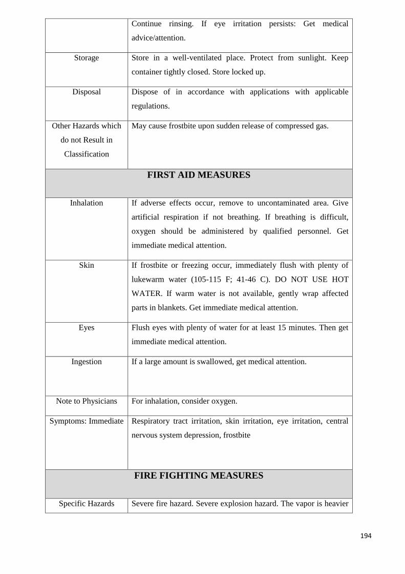
194
Continue rinsing. If eye irritation persists: Get medical
advice/attention.
Storage Store in a well-ventilated place. Protect from sunlight. Keep
container tightly closed. Store locked up.
Disposal Dispose of in accordance with applications with applicable
regulations.
Other Hazards which
do not Result in
Classification
May cause frostbite upon sudden release of compressed gas.
FIRST AID MEASURES
Inhalation If adverse effects occur, remove to uncontaminated area. Give
artificial respiration if not breathing. If breathing is difficult,
oxygen should be administered by qualified personnel. Get
immediate medical attention.
Skin If frostbite or freezing occur, immediately flush with plenty of
lukewarm water (105-115 F; 41-46 C). DO NOT USE HOT
WATER. If warm water is not available, gently wrap affected
parts in blankets. Get immediate medical attention.
Eyes Flush eyes with plenty of water for at least 15 minutes. Then get
immediate medical attention.
Ingestion If a large amount is swallowed, get medical attention.
Note to Physicians For inhalation, consider oxygen.
Symptoms: Immediate Respiratory tract irritation, skin irritation, eye irritation, central
nervous system depression, frostbite
FIRE FIGHTING MEASURES
Specific Hazards Severe fire hazard. Severe explosion hazard. The vapor is heavier
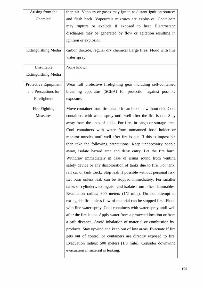
195
Arising from the
Chemical
than air. Vapours or gases may ignite at distant ignition sources
and flash back. Vapour/air mixtures are explosive. Containers
may rupture or explode if exposed to heat. Electrostatic
discharges may be generated by flow or agitation resulting in
ignition or explosion.
Extinguishing Media carbon dioxide, regular dry chemical Large fires: Flood with fine
water spray
Unsuitable
Extinguishing Media
None known
Protective Equipment
and Precautions for
Firefighters
Wear full protective firefighting gear including self-contained
breathing apparatus (SCBA) for protection against possible
exposure.
Fire Fighting
Measures
Move container from fire area if it can be done without risk. Cool
containers with water spray until well after the fire is out. Stay
away from the ends of tanks. For fires in cargo or storage area:
Cool containers with water from unmanned hose holder or
monitor nozzles until well after fire is out. If this is impossible
then take the following precautions: Keep unnecessary people
away, isolate hazard area and deny entry. Let the fire burn.
Withdraw immediately in case of rising sound from venting
safety device or any discoloration of tanks due to fire. For tank,
rail car or tank truck: Stop leak if possible without personal risk.
Let burn unless leak can be stopped immediately. For smaller
tanks or cylinders, extinguish and isolate from other flammables.
Evacuation radius: 800 meters (1/2 mile). Do not attempt to
extinguish fire unless flow of material can be stopped first. Flood
with fine water spray. Cool containers with water spray until well
after the fire is out. Apply water from a protected location or from
a safe distance. Avoid inhalation of material or combustion by-
products. Stay upwind and keep out of low areas. Evacuate if fire
gets out of control or containers are directly exposed to fire.
Evacuation radius: 500 meters (1/3 mile). Consider downwind
evacuation if material is leaking.
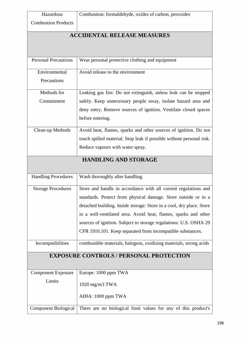
196
Hazardous
Combustion Products
Combustion: formaldehyde, oxides of carbon, peroxides
ACCIDENTAL RELEASE MEASURES
Personal Precautions Wear personal protective clothing and equipment
Environmental
Precautions
Avoid release to the environment
Methods for
Containment
Leaking gas fire: Do not extinguish, unless leak can be stopped
safely. Keep unnecessary people away, isolate hazard area and
deny entry. Remove sources of ignition. Ventilate closed spaces
before entering.
Clean-up Methods Avoid heat, flames, sparks and other sources of ignition. Do not
touch spilled material. Stop leak if possible without personal risk.
Reduce vapours with water spray.
HANDLING AND STORAGE
Handling Procedures Wash thoroughly after handling.
Storage Procedures Store and handle in accordance with all current regulations and
standards. Protect from physical damage. Store outside or in a
detached building. Inside storage: Store in a cool, dry place. Store
in a well-ventilated area. Avoid heat, flames, sparks and other
sources of ignition. Subject to storage regulations: U.S. OSHA 29
CFR 1910.101. Keep separated from incompatible substances.
Incompatibilities combustible materials, halogens, oxidizing materials, strong acids
EXPOSURE CONTROLS / PERSONAL PROTECTION
Component Exposure
Limits
Europe: 1000 ppm TWA
1920 mg/m3 TWA
AIHA: 1000 ppm TWA
Component Biological There are no biological limit values for any of this product's
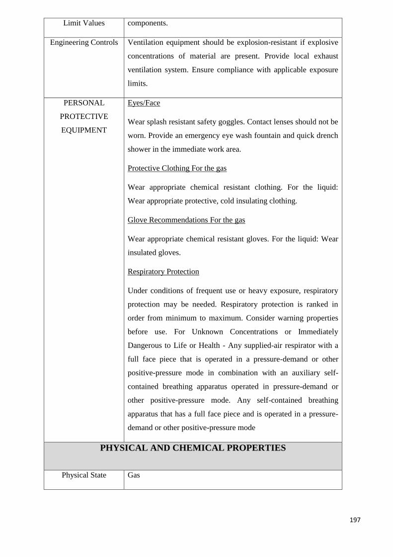
197
Limit Values components.
Engineering Controls Ventilation equipment should be explosion-resistant if explosive
concentrations of material are present. Provide local exhaust
ventilation system. Ensure compliance with applicable exposure
limits.
PERSONAL
PROTECTIVE
EQUIPMENT
Eyes/Face
Wear splash resistant safety goggles. Contact lenses should not be
worn. Provide an emergency eye wash fountain and quick drench
shower in the immediate work area.
Protective Clothing For the gas
Wear appropriate chemical resistant clothing. For the liquid:
Wear appropriate protective, cold insulating clothing.
Glove Recommendations For the gas
Wear appropriate chemical resistant gloves. For the liquid: Wear
insulated gloves.
Respiratory Protection
Under conditions of frequent use or heavy exposure, respiratory
protection may be needed. Respiratory protection is ranked in
order from minimum to maximum. Consider warning properties
before use. For Unknown Concentrations or Immediately
Dangerous to Life or Health - Any supplied-air respirator with a
full face piece that is operated in a pressure-demand or other
positive-pressure mode in combination with an auxiliary self-
contained breathing apparatus operated in pressure-demand or
other positive-pressure mode. Any self-contained breathing
apparatus that has a full face piece and is operated in a pressure-
demand or other positive-pressure mode
PHYSICAL AND CHEMICAL PROPERTIES
Physical State Gas
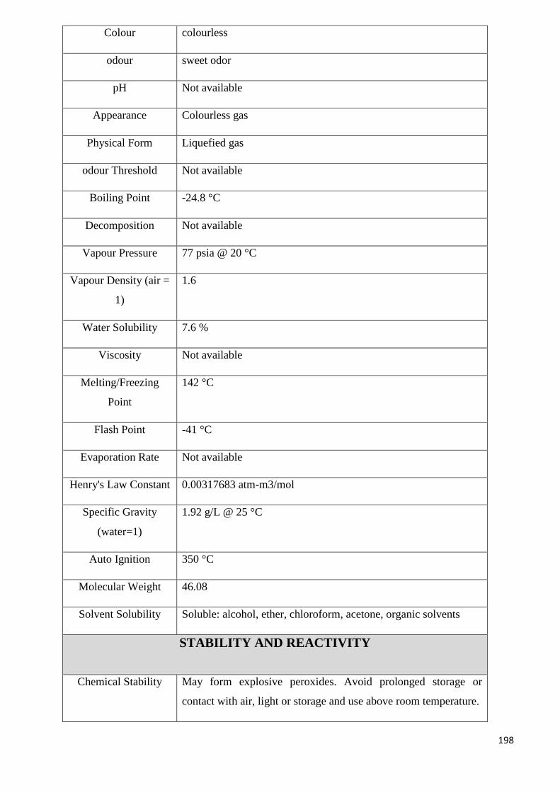
198
Colour colourless
odour sweet odor
pH Not available
Appearance Colourless gas
Physical Form Liquefied gas
odour Threshold Not available
Boiling Point -24.8 °C
Decomposition Not available
Vapour Pressure 77 psia @ 20 °C
Vapour Density (air =
1)
1.6
Water Solubility 7.6 %
Viscosity Not available
Melting/Freezing
Point
142 °C
Flash Point -41 °C
Evaporation Rate Not available
Henry's Law Constant 0.00317683 atm-m3/mol
Specific Gravity
(water=1)
1.92 g/L @ 25 °C
Auto Ignition 350 °C
Molecular Weight 46.08
Solvent Solubility Soluble: alcohol, ether, chloroform, acetone, organic solvents
STABILITY AND REACTIVITY
Chemical Stability May form explosive peroxides. Avoid prolonged storage or
contact with air, light or storage and use above room temperature.
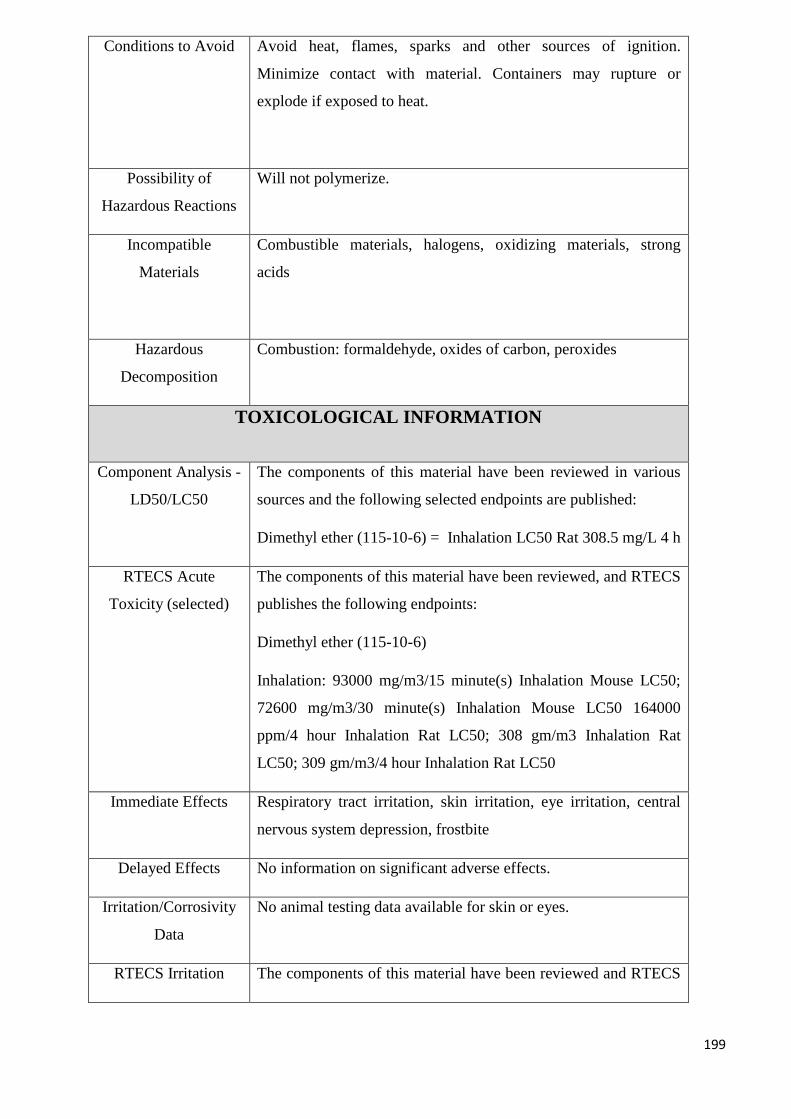
199
Conditions to Avoid Avoid heat, flames, sparks and other sources of ignition.
Minimize contact with material. Containers may rupture or
explode if exposed to heat.
Possibility of
Hazardous Reactions
Will not polymerize.
Incompatible
Materials
Combustible materials, halogens, oxidizing materials, strong
acids
Hazardous
Decomposition
Combustion: formaldehyde, oxides of carbon, peroxides
TOXICOLOGICAL INFORMATION
Component Analysis -
LD50/LC50
The components of this material have been reviewed in various
sources and the following selected endpoints are published:
Dimethyl ether (115-10-6) = Inhalation LC50 Rat 308.5 mg/L 4 h
RTECS Acute
Toxicity (selected)
The components of this material have been reviewed, and RTECS
publishes the following endpoints:
Dimethyl ether (115-10-6)
Inhalation: 93000 mg/m3/15 minute(s) Inhalation Mouse LC50;
72600 mg/m3/30 minute(s) Inhalation Mouse LC50 164000
ppm/4 hour Inhalation Rat LC50; 308 gm/m3 Inhalation Rat
LC50; 309 gm/m3/4 hour Inhalation Rat LC50
Immediate Effects Respiratory tract irritation, skin irritation, eye irritation, central
nervous system depression, frostbite
Delayed Effects No information on significant adverse effects.
Irritation/Corrosivity
Data
No animal testing data available for skin or eyes.
RTECS Irritation The components of this material have been reviewed and RTECS
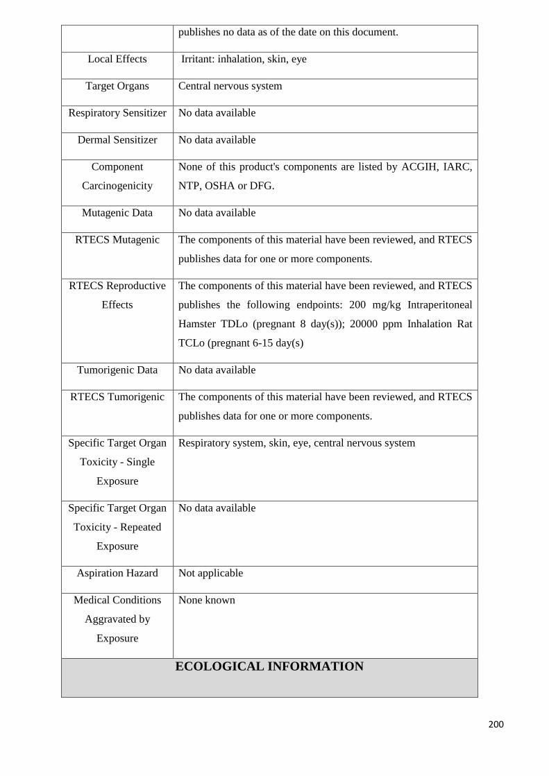
200
publishes no data as of the date on this document.
Local Effects Irritant: inhalation, skin, eye
Target Organs Central nervous system
Respiratory Sensitizer No data available
Dermal Sensitizer No data available
Component
Carcinogenicity
None of this product's components are listed by ACGIH, IARC,
NTP, OSHA or DFG.
Mutagenic Data No data available
RTECS Mutagenic The components of this material have been reviewed, and RTECS
publishes data for one or more components.
RTECS Reproductive
Effects
The components of this material have been reviewed, and RTECS
publishes the following endpoints: 200 mg/kg Intraperitoneal
Hamster TDLo (pregnant 8 day(s)); 20000 ppm Inhalation Rat
TCLo (pregnant 6-15 day(s)
Tumorigenic Data No data available
RTECS Tumorigenic The components of this material have been reviewed, and RTECS
publishes data for one or more components.
Specific Target Organ
Toxicity - Single
Exposure
Respiratory system, skin, eye, central nervous system
Specific Target Organ
Toxicity - Repeated
Exposure
No data available
Aspiration Hazard Not applicable
Medical Conditions
Aggravated by
Exposure
None known
ECOLOGICAL INFORMATION
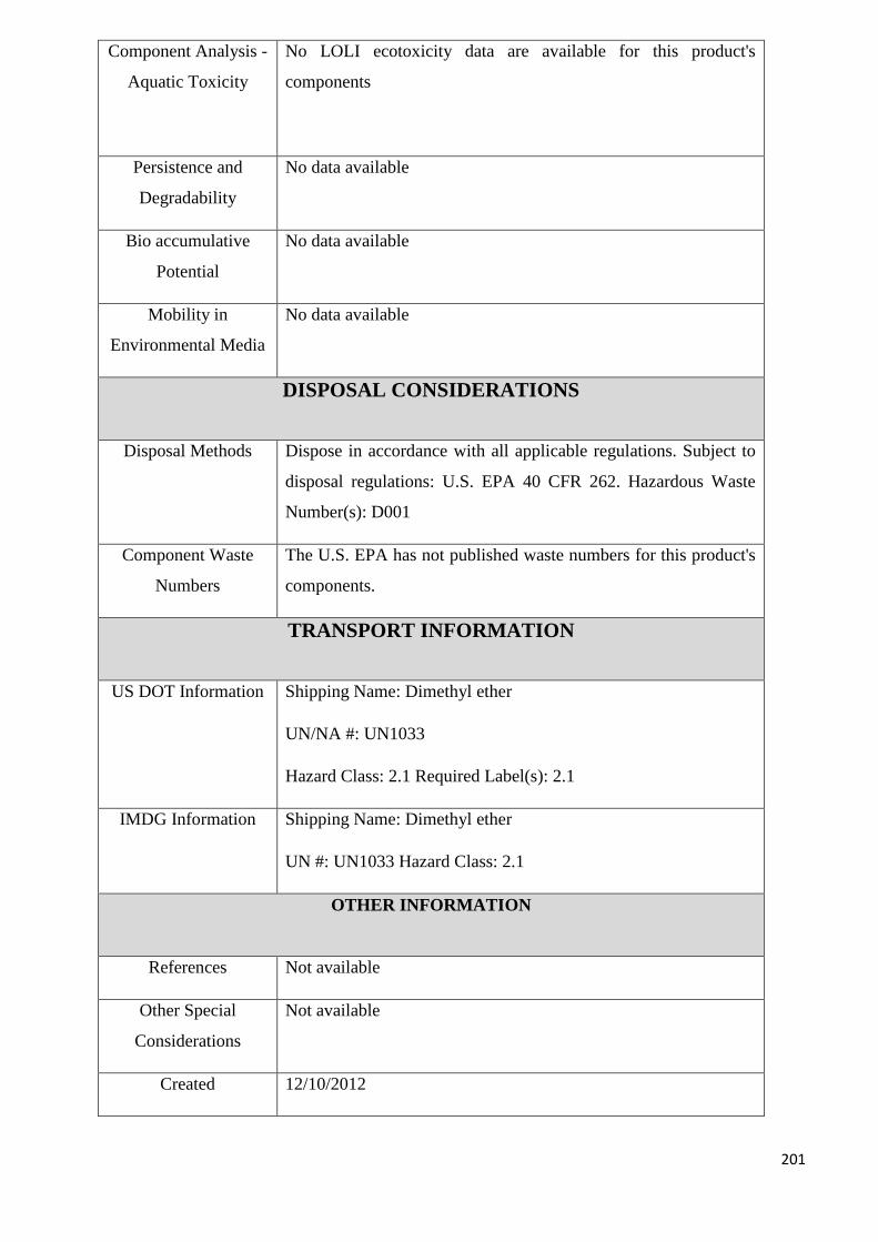
201
Component Analysis -
Aquatic Toxicity
No LOLI ecotoxicity data are available for this product's
components
Persistence and
Degradability
No data available
Bio accumulative
Potential
No data available
Mobility in
Environmental Media
No data available
DISPOSAL CONSIDERATIONS
Disposal Methods Dispose in accordance with all applicable regulations. Subject to
disposal regulations: U.S. EPA 40 CFR 262. Hazardous Waste
Number(s): D001
Component Waste
Numbers
The U.S. EPA has not published waste numbers for this product's
components.
TRANSPORT INFORMATION
US DOT Information Shipping Name: Dimethyl ether
UN/NA #: UN1033
Hazard Class: 2.1 Required Label(s): 2.1
IMDG Information Shipping Name: Dimethyl ether
UN #: UN1033 Hazard Class: 2.1
OTHER INFORMATION
References Not available
Other Special
Considerations
Not available
Created 12/10/2012
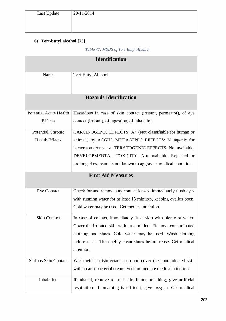
202
Last Update 20/11/2014
6) Tert-butyl alcohol [73]
Table 47: MSDS of Tert-Butyl Alcohol
Identification
Name Tert-Butyl Alcohol
Hazards Identification
Potential Acute Health
Effects
Hazardous in case of skin contact (irritant, permeator), of eye
contact (irritant), of ingestion, of inhalation.
Potential Chronic
Health Effects
CARCINOGENIC EFFECTS: A4 (Not classifiable for human or
animal.) by ACGIH. MUTAGENIC EFFECTS: Mutagenic for
bacteria and/or yeast. TERATOGENIC EFFECTS: Not available.
DEVELOPMENTAL TOXICITY: Not available. Repeated or
prolonged exposure is not known to aggravate medical condition.
First Aid Measures
Eye Contact Check for and remove any contact lenses. Immediately flush eyes
with running water for at least 15 minutes, keeping eyelids open.
Cold water may be used. Get medical attention.
Skin Contact In case of contact, immediately flush skin with plenty of water.
Cover the irritated skin with an emollient. Remove contaminated
clothing and shoes. Cold water may be used. Wash clothing
before reuse. Thoroughly clean shoes before reuse. Get medical
attention.
Serious Skin Contact Wash with a disinfectant soap and cover the contaminated skin
with an anti-bacterial cream. Seek immediate medical attention.
Inhalation If inhaled, remove to fresh air. If not breathing, give artificial
respiration. If breathing is difficult, give oxygen. Get medical
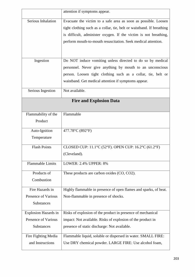
203
attention if symptoms appear.
Serious Inhalation Evacuate the victim to a safe area as soon as possible. Loosen
tight clothing such as a collar, tie, belt or waistband. If breathing
is difficult, administer oxygen. If the victim is not breathing,
perform mouth-to-mouth resuscitation. Seek medical attention.
Ingestion Do NOT induce vomiting unless directed to do so by medical
personnel. Never give anything by mouth to an unconscious
person. Loosen tight clothing such as a collar, tie, belt or
waistband. Get medical attention if symptoms appear.
Serious Ingestion Not available.
Fire and Explosion Data
Flammability of the
Product
Flammable
Auto-Ignition
Temperature
477.78°C (892°F)
Flash Points CLOSED CUP: 11.1°C (52°F). OPEN CUP: 16.2°C (61.2°F)
(Cleveland).
Flammable Limits LOWER: 2.4% UPPER: 8%
Products of
Combustion
These products are carbon oxides (CO, CO2).
Fire Hazards in
Presence of Various
Substances
Highly flammable in presence of open flames and sparks, of heat.
Non-flammable in presence of shocks.
Explosion Hazards in
Presence of Various
Substances
Risks of explosion of the product in presence of mechanical
impact: Not available. Risks of explosion of the product in
presence of static discharge: Not available.
Fire Fighting Media
and Instructions
Flammable liquid, soluble or dispersed in water. SMALL FIRE:
Use DRY chemical powder. LARGE FIRE: Use alcohol foam,
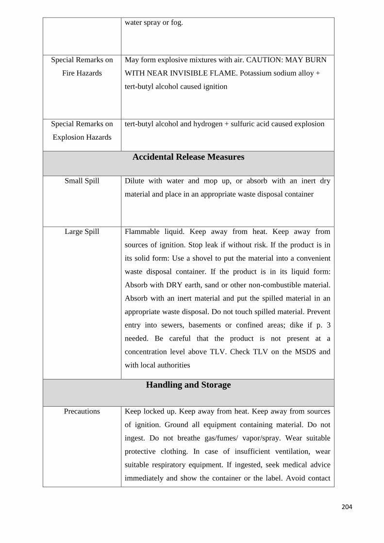
204
water spray or fog.
Special Remarks on
Fire Hazards
May form explosive mixtures with air. CAUTION: MAY BURN
WITH NEAR INVISIBLE FLAME. Potassium sodium alloy +
tert-butyl alcohol caused ignition
Special Remarks on
Explosion Hazards
tert-butyl alcohol and hydrogen + sulfuric acid caused explosion
Accidental Release Measures
Small Spill Dilute with water and mop up, or absorb with an inert dry
material and place in an appropriate waste disposal container
Large Spill Flammable liquid. Keep away from heat. Keep away from
sources of ignition. Stop leak if without risk. If the product is in
its solid form: Use a shovel to put the material into a convenient
waste disposal container. If the product is in its liquid form:
Absorb with DRY earth, sand or other non-combustible material.
Absorb with an inert material and put the spilled material in an
appropriate waste disposal. Do not touch spilled material. Prevent
entry into sewers, basements or confined areas; dike if p. 3
needed. Be careful that the product is not present at a
concentration level above TLV. Check TLV on the MSDS and
with local authorities
Handling and Storage
Precautions Keep locked up. Keep away from heat. Keep away from sources
of ignition. Ground all equipment containing material. Do not
ingest. Do not breathe gas/fumes/ vapor/spray. Wear suitable
protective clothing. In case of insufficient ventilation, wear
suitable respiratory equipment. If ingested, seek medical advice
immediately and show the container or the label. Avoid contact
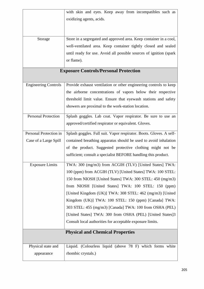
205
with skin and eyes. Keep away from incompatibles such as
oxidizing agents, acids.
Storage Store in a segregated and approved area. Keep container in a cool,
well-ventilated area. Keep container tightly closed and sealed
until ready for use. Avoid all possible sources of ignition (spark
or flame).
Exposure Controls/Personal Protection
Engineering Controls Provide exhaust ventilation or other engineering controls to keep
the airborne concentrations of vapors below their respective
threshold limit value. Ensure that eyewash stations and safety
showers are proximal to the work-station location.
Personal Protection Splash goggles. Lab coat. Vapor respirator. Be sure to use an
approved/certified respirator or equivalent. Gloves.
Personal Protection in
Case of a Large Spill
Splash goggles. Full suit. Vapor respirator. Boots. Gloves. A self-
contained breathing apparatus should be used to avoid inhalation
of the product. Suggested protective clothing might not be
sufficient; consult a specialist BEFORE handling this product.
Exposure Limits TWA: 300 (mg/m3) from ACGIH (TLV) [United States] TWA:
100 (ppm) from ACGIH (TLV) [United States] TWA: 100 STEL:
150 from NIOSH [United States] TWA: 300 STEL: 450 (mg/m3)
from NIOSH [United States] TWA: 100 STEL: 150 (ppm)
[United Kingdom (UK)] TWA: 308 STEL: 462 (mg/m3) [United
Kingdom (UK)] TWA: 100 STEL: 150 (ppm) [Canada] TWA:
303 STEL: 455 (mg/m3) [Canada] TWA: 100 from OSHA (PEL)
[United States] TWA: 300 from OSHA (PEL) [United States]3
Consult local authorities for acceptable exposure limits.
Physical and Chemical Properties
Physical state and
appearance
Liquid. (Colourless liquid (above 78 F) which forms white
rhombic crystals.)
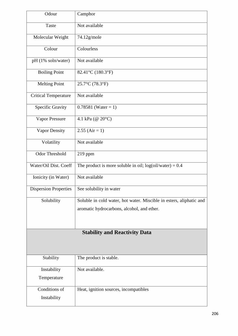
206
Odour Camphor
Taste Not available
Molecular Weight 74.12g/mole
Colour Colourless
pH (1% soln/water) Not available
Boiling Point 82.41°C (180.3°F)
Melting Point 25.7°C (78.3°F)
Critical Temperature Not available
Specific Gravity 0.78581 (Water = 1)
Vapor Pressure 4.1 kPa (@ 20°C)
Vapor Density 2.55 (Air = 1)
Volatility Not available
Odor Threshold 219 ppm
Water/Oil Dist. Coeff The product is more soluble in oil; log(oil/water) = 0.4
Ionicity (in Water) Not available
Dispersion Properties See solubility in water
Solubility Soluble in cold water, hot water. Miscible in esters, aliphatic and
aromatic hydrocarbons, alcohol, and ether.
Stability and Reactivity Data
Stability The product is stable.
Instability
Temperature
Not available.
Conditions of
Instability
Heat, ignition sources, incompatibles
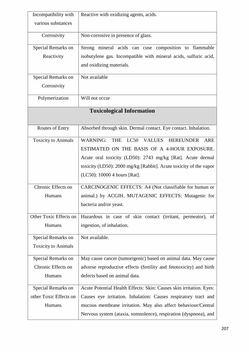
207
Incompatibility with
various substances
Reactive with oxidizing agents, acids.
Corrosivity Non-corrosive in presence of glass.
Special Remarks on
Reactivity
Strong mineral acids can cuse composition to flammable
isobutylene gas. Incompatible with mineral acids, sulfuric acid,
and oxidizing materials.
Special Remarks on
Corrosivity
Not available
Polymerization Will not occur
Toxicological Information
Routes of Entry Absorbed through skin. Dermal contact. Eye contact. Inhalation.
Toxicity to Animals WARNING: THE LC50 VALUES HEREUNDER ARE
ESTIMATED ON THE BASIS OF A 4-HOUR EXPOSURE.
Acute oral toxicity (LD50): 2743 mg/kg [Rat]. Acute dermal
toxicity (LD50): 2000 mg/kg [Rabbit]. Acute toxicity of the vapor
(LC50): 10000 4 hours [Rat].
Chronic Effects on
Humans
CARCINOGENIC EFFECTS: A4 (Not classifiable for human or
animal.) by ACGIH. MUTAGENIC EFFECTS: Mutagenic for
bacteria and/or yeast.
Other Toxic Effects on
Humans
Hazardous in case of skin contact (irritant, permeator), of
ingestion, of inhalation.
Special Remarks on
Toxicity to Animals
Not available.
Special Remarks on
Chronic Effects on
Humans
May cause cancer (tumorigenic) based on animal data. May cause
adverse reproductive effects (fertility and fetotoxicity) and birth
defects based on animal data.
Special Remarks on
other Toxic Effects on
Humans
Acute Potential Health Effects: Skin: Causes skin irritation. Eyes:
Causes eye irritation. Inhalation: Causes respiratory tract and
mucous membrane irritation. May also affect behaviour/Central
Nervous system (ataxia, somnolence), respiration (dyspnoea), and
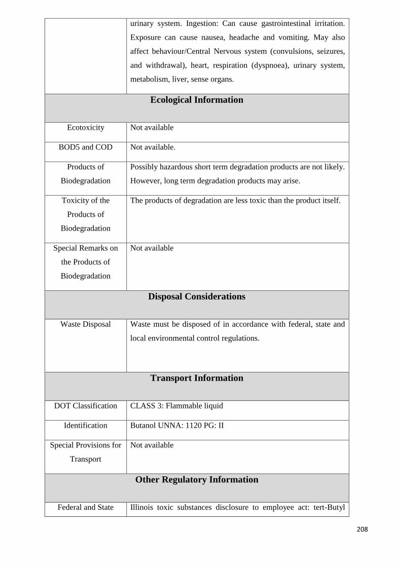
208
urinary system. Ingestion: Can cause gastrointestinal irritation.
Exposure can cause nausea, headache and vomiting. May also
affect behaviour/Central Nervous system (convulsions, seizures,
and withdrawal), heart, respiration (dyspnoea), urinary system,
metabolism, liver, sense organs.
Ecological Information
Ecotoxicity Not available
BOD5 and COD Not available.
Products of
Biodegradation
Possibly hazardous short term degradation products are not likely.
However, long term degradation products may arise.
Toxicity of the
Products of
Biodegradation
The products of degradation are less toxic than the product itself.
Special Remarks on
the Products of
Biodegradation
Not available
Disposal Considerations
Waste Disposal Waste must be disposed of in accordance with federal, state and
local environmental control regulations.
Transport Information
DOT Classification CLASS 3: Flammable liquid
Identification Butanol UNNA: 1120 PG: II
Special Provisions for
Transport
Not available
Other Regulatory Information
Federal and State Illinois toxic substances disclosure to employee act: tert-Butyl
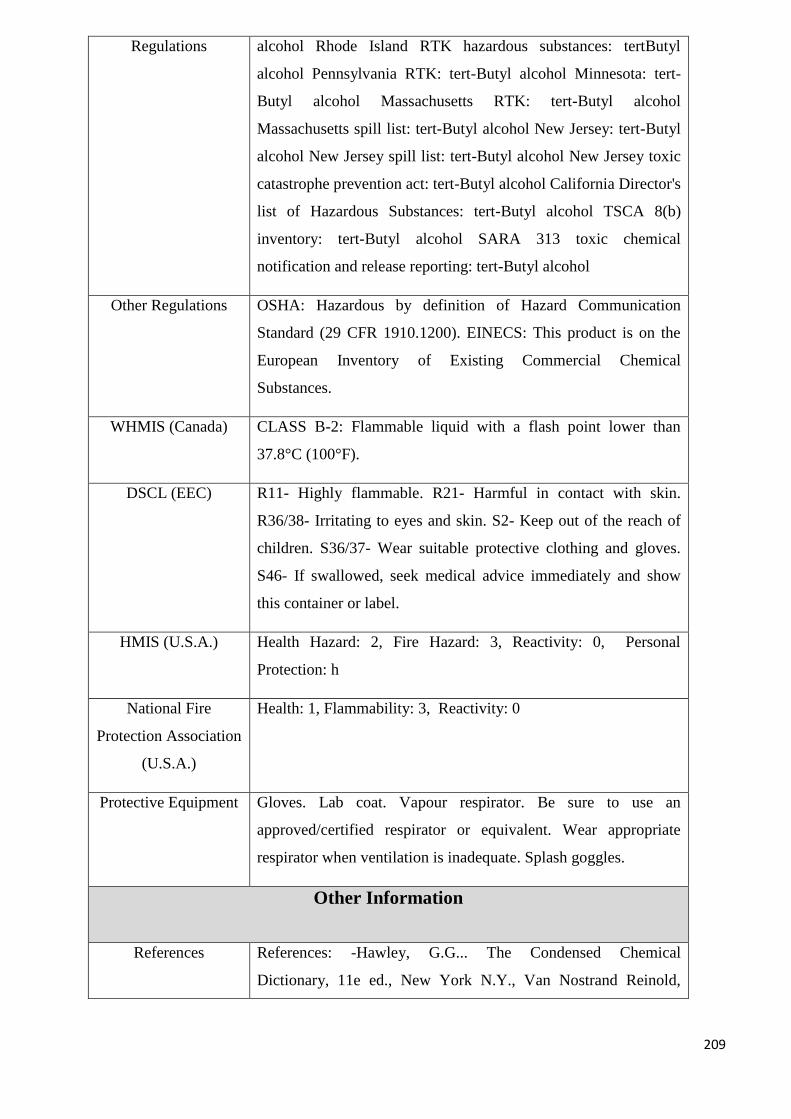
209
Regulations alcohol Rhode Island RTK hazardous substances: tertButyl
alcohol Pennsylvania RTK: tert-Butyl alcohol Minnesota: tert-
Butyl alcohol Massachusetts RTK: tert-Butyl alcohol
Massachusetts spill list: tert-Butyl alcohol New Jersey: tert-Butyl
alcohol New Jersey spill list: tert-Butyl alcohol New Jersey toxic
catastrophe prevention act: tert-Butyl alcohol California Director's
list of Hazardous Substances: tert-Butyl alcohol TSCA 8(b)
inventory: tert-Butyl alcohol SARA 313 toxic chemical
notification and release reporting: tert-Butyl alcohol
Other Regulations OSHA: Hazardous by definition of Hazard Communication
Standard (29 CFR 1910.1200). EINECS: This product is on the
European Inventory of Existing Commercial Chemical
Substances.
WHMIS (Canada) CLASS B-2: Flammable liquid with a flash point lower than
37.8°C (100°F).
DSCL (EEC) R11- Highly flammable. R21- Harmful in contact with skin.
R36/38- Irritating to eyes and skin. S2- Keep out of the reach of
children. S36/37- Wear suitable protective clothing and gloves.
S46- If swallowed, seek medical advice immediately and show
this container or label.
HMIS (U.S.A.) Health Hazard: 2, Fire Hazard: 3, Reactivity: 0, Personal
Protection: h
National Fire
Protection Association
(U.S.A.)
Health: 1, Flammability: 3, Reactivity: 0
Protective Equipment Gloves. Lab coat. Vapour respirator. Be sure to use an
approved/certified respirator or equivalent. Wear appropriate
respirator when ventilation is inadequate. Splash goggles.
Other Information
References References: -Hawley, G.G... The Condensed Chemical
Dictionary, 11e ed., New York N.Y., Van Nostrand Reinold,
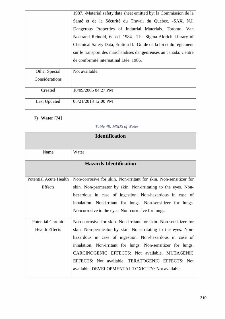
210
1987. -Material safety data sheet emitted by: la Commission de la
Santé et de la Sécurité du Travail du Québec. -SAX, N.I.
Dangerous Properties of Indutrial Materials. Toronto, Van
Nostrand Reinold, 6e ed. 1984. -The Sigma-Aldrich Library of
Chemical Safety Data, Edition II. -Guide de la loi et du règlement
sur le transport des marchandises dangeureuses au canada. Centre
de conformité internatinal Ltée. 1986.
Other Special
Considerations
Not available.
Created 10/09/2005 04:27 PM
Last Updated 05/21/2013 12:00 PM
7) Water [74]
Table 48: MSDS of Water
Identification
Name Water
Hazards Identification
Potential Acute Health
Effects
Non-corrosive for skin. Non-irritant for skin. Non-sensitizer for
skin. Non-permeator by skin. Non-irritating to the eyes. Non-
hazardous in case of ingestion. Non-hazardous in case of
inhalation. Non-irritant for lungs. Non-sensitizer for lungs.
Noncorrosive to the eyes. Non-corrosive for lungs.
Potential Chronic
Health Effects
Non-corrosive for skin. Non-irritant for skin. Non-sensitizer for
skin. Non-permeator by skin. Non-irritating to the eyes. Non-
hazardous in case of ingestion. Non-hazardous in case of
inhalation. Non-irritant for lungs. Non-sensitizer for lungs.
CARCINOGENIC EFFECTS: Not available. MUTAGENIC
EFFECTS: Not available. TERATOGENIC EFFECTS: Not
available. DEVELOPMENTAL TOXICITY: Not available.
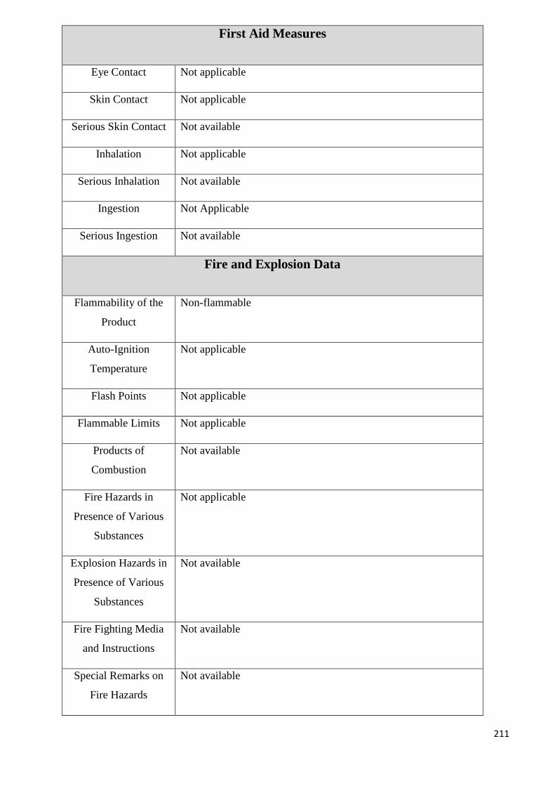
211
First Aid Measures
Eye Contact Not applicable
Skin Contact Not applicable
Serious Skin Contact Not available
Inhalation Not applicable
Serious Inhalation Not available
Ingestion Not Applicable
Serious Ingestion Not available
Fire and Explosion Data
Flammability of the
Product
Non-flammable
Auto-Ignition
Temperature
Not applicable
Flash Points Not applicable
Flammable Limits Not applicable
Products of
Combustion
Not available
Fire Hazards in
Presence of Various
Substances
Not applicable
Explosion Hazards in
Presence of Various
Substances
Not available
Fire Fighting Media
and Instructions
Not available
Special Remarks on
Fire Hazards
Not available
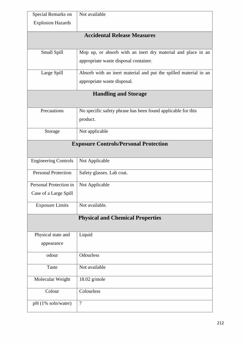
212
Special Remarks on
Explosion Hazards
Not available
Accidental Release Measures
Small Spill Mop up, or absorb with an inert dry material and place in an
appropriate waste disposal container.
Large Spill Absorb with an inert material and put the spilled material in an
appropriate waste disposal.
Handling and Storage
Precautions No specific safety phrase has been found applicable for this
product.
Storage Not applicable
Exposure Controls/Personal Protection
Engineering Controls Not Applicable
Personal Protection Safety glasses. Lab coat.
Personal Protection in
Case of a Large Spill
Not Applicable
Exposure Limits Not available.
Physical and Chemical Properties
Physical state and
appearance
Liquid
odour Odourless
Taste Not available
Molecular Weight 18.02 g/mole
Colour Colourless
pH (1% soln/water) 7
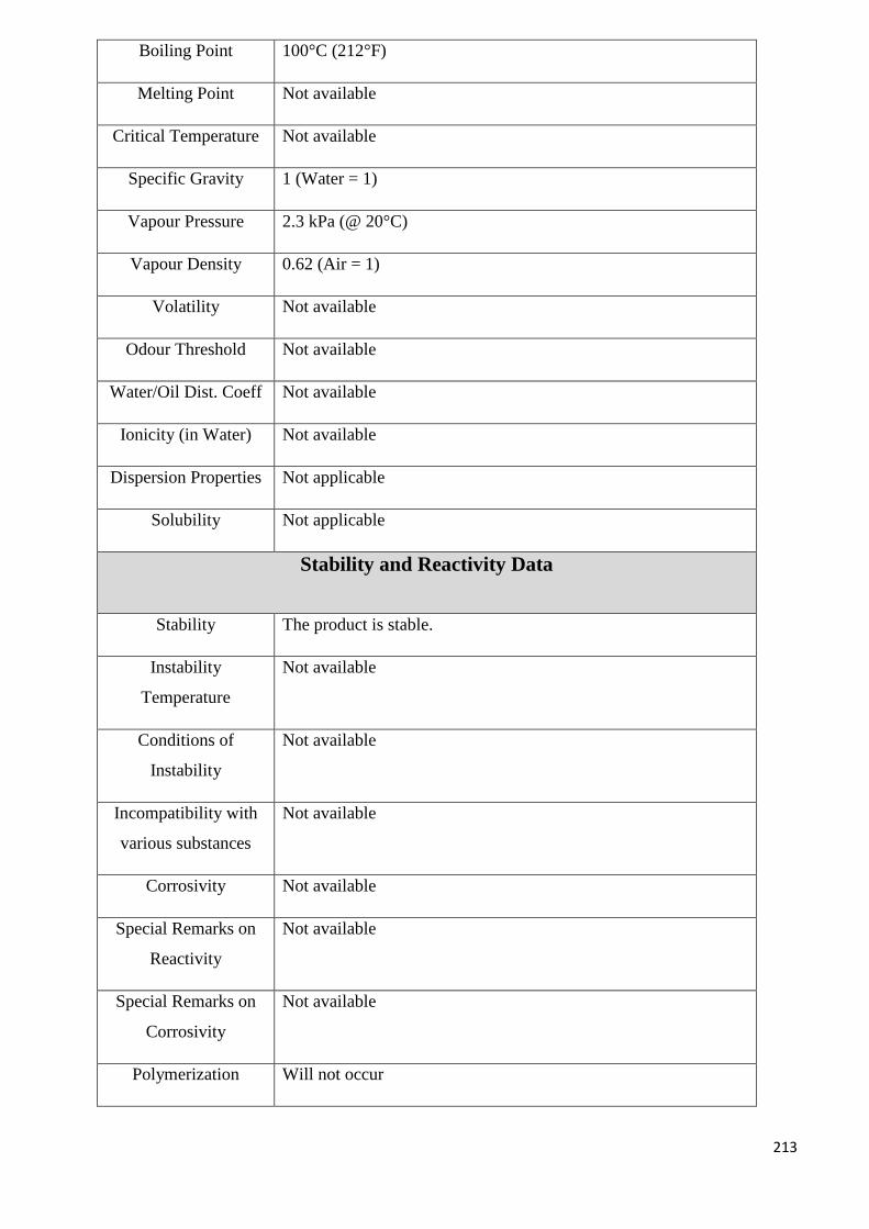
213
Boiling Point 100°C (212°F)
Melting Point Not available
Critical Temperature Not available
Specific Gravity 1 (Water = 1)
Vapour Pressure 2.3 kPa (@ 20°C)
Vapour Density 0.62 (Air = 1)
Volatility Not available
Odour Threshold Not available
Water/Oil Dist. Coeff Not available
Ionicity (in Water) Not available
Dispersion Properties Not applicable
Solubility Not applicable
Stability and Reactivity Data
Stability The product is stable.
Instability
Temperature
Not available
Conditions of
Instability
Not available
Incompatibility with
various substances
Not available
Corrosivity Not available
Special Remarks on
Reactivity
Not available
Special Remarks on
Corrosivity
Not available
Polymerization Will not occur
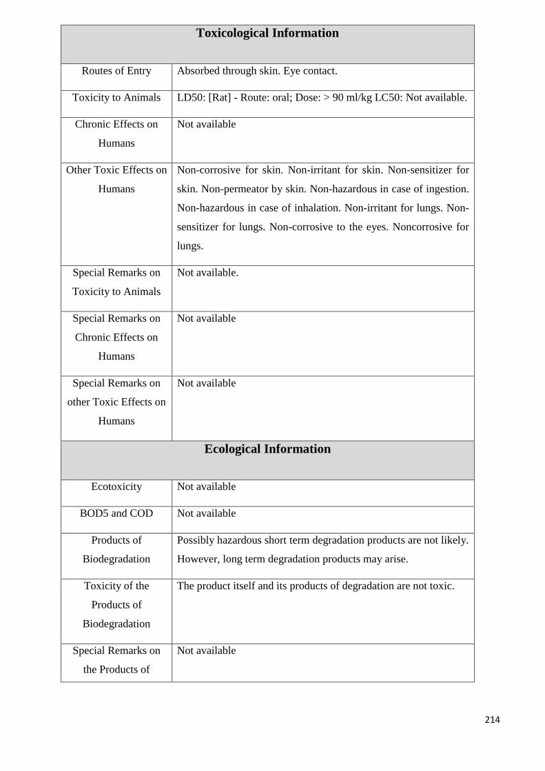
214
Toxicological Information
Routes of Entry Absorbed through skin. Eye contact.
Toxicity to Animals LD50: [Rat] - Route: oral; Dose: > 90 ml/kg LC50: Not available.
Chronic Effects on
Humans
Not available
Other Toxic Effects on
Humans
Non-corrosive for skin. Non-irritant for skin. Non-sensitizer for
skin. Non-permeator by skin. Non-hazardous in case of ingestion.
Non-hazardous in case of inhalation. Non-irritant for lungs. Non-
sensitizer for lungs. Non-corrosive to the eyes. Noncorrosive for
lungs.
Special Remarks on
Toxicity to Animals
Not available.
Special Remarks on
Chronic Effects on
Humans
Not available
Special Remarks on
other Toxic Effects on
Humans
Not available
Ecological Information
Ecotoxicity Not available
BOD5 and COD Not available
Products of
Biodegradation
Possibly hazardous short term degradation products are not likely.
However, long term degradation products may arise.
Toxicity of the
Products of
Biodegradation
The product itself and its products of degradation are not toxic.
Special Remarks on
the Products of
Not available
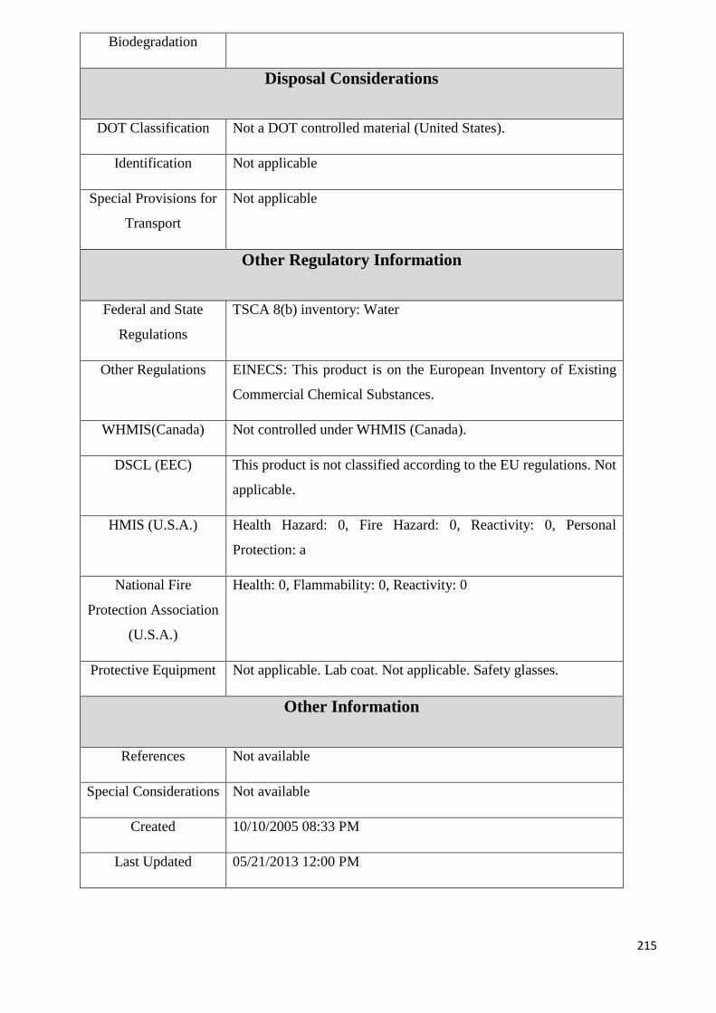
215
Biodegradation
Disposal Considerations
DOT Classification Not a DOT controlled material (United States).
Identification Not applicable
Special Provisions for
Transport
Not applicable
Other Regulatory Information
Federal and State
Regulations
TSCA 8(b) inventory: Water
Other Regulations EINECS: This product is on the European Inventory of Existing
Commercial Chemical Substances.
WHMIS(Canada) Not controlled under WHMIS (Canada).
DSCL (EEC) This product is not classified according to the EU regulations. Not
applicable.
HMIS (U.S.A.) Health Hazard: 0, Fire Hazard: 0, Reactivity: 0, Personal
Protection: a
National Fire
Protection Association
(U.S.A.)
Health: 0, Flammability: 0, Reactivity: 0
Protective Equipment Not applicable. Lab coat. Not applicable. Safety glasses.
Other Information
References Not available
Special Considerations Not available
Created 10/10/2005 08:33 PM
Last Updated 05/21/2013 12:00 PM
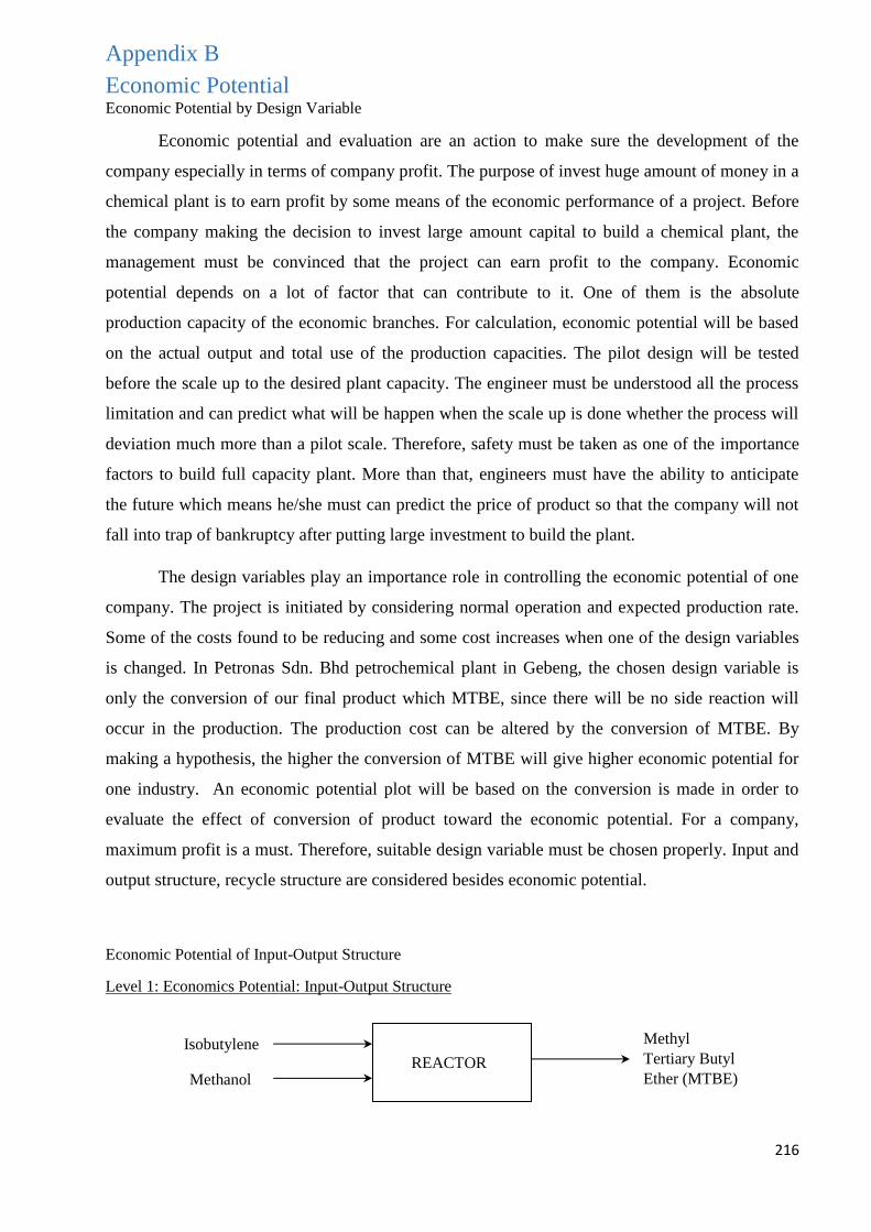
216
Appendix B
Economic Potential Economic Potential by Design Variable
Economic potential and evaluation are an action to make sure the development of the
company especially in terms of company profit. The purpose of invest huge amount of money in a
chemical plant is to earn profit by some means of the economic performance of a project. Before
the company making the decision to invest large amount capital to build a chemical plant, the
management must be convinced that the project can earn profit to the company. Economic
potential depends on a lot of factor that can contribute to it. One of them is the absolute
production capacity of the economic branches. For calculation, economic potential will be based
on the actual output and total use of the production capacities. The pilot design will be tested
before the scale up to the desired plant capacity. The engineer must be understood all the process
limitation and can predict what will be happen when the scale up is done whether the process will
deviation much more than a pilot scale. Therefore, safety must be taken as one of the importance
factors to build full capacity plant. More than that, engineers must have the ability to anticipate
the future which means he/she must can predict the price of product so that the company will not
fall into trap of bankruptcy after putting large investment to build the plant.
The design variables play an importance role in controlling the economic potential of one
company. The project is initiated by considering normal operation and expected production rate.
Some of the costs found to be reducing and some cost increases when one of the design variables
is changed. In Petronas Sdn. Bhd petrochemical plant in Gebeng, the chosen design variable is
only the conversion of our final product which MTBE, since there will be no side reaction will
occur in the production. The production cost can be altered by the conversion of MTBE. By
making a hypothesis, the higher the conversion of MTBE will give higher economic potential for
one industry. An economic potential plot will be based on the conversion is made in order to
evaluate the effect of conversion of product toward the economic potential. For a company,
maximum profit is a must. Therefore, suitable design variable must be chosen properly. Input and
output structure, recycle structure are considered besides economic potential.
Economic Potential of Input-Output Structure
Level 1: Economics Potential: Input-Output Structure
Methyl
Tertiary Butyl
Ether (MTBE)
Isobutylene
Methanol REACTOR
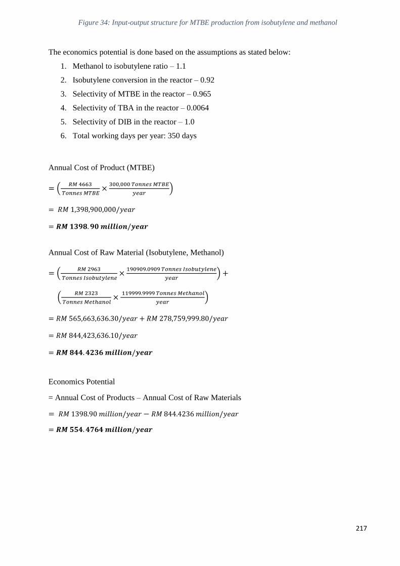
217
Figure 34: Input-output structure for MTBE production from isobutylene and methanol
The economics potential is done based on the assumptions as stated below:
1. Methanol to isobutylene ratio – 1.1
2. Isobutylene conversion in the reactor – 0.92
3. Selectivity of MTBE in the reactor – 0.965
4. Selectivity of TBA in the reactor – 0.0064
5. Selectivity of DIB in the reactor – 1.0
6. Total working days per year: 350 days
Annual Cost of Product (MTBE)
= (𝑅𝑀 4663
𝑇𝑜𝑛𝑛𝑒𝑠 𝑀𝑇𝐵𝐸×
300,000 𝑇𝑜𝑛𝑛𝑒𝑠 𝑀𝑇𝐵𝐸
𝑦𝑒𝑎𝑟)
= 𝑅𝑀 1,398,900,000/𝑦𝑒𝑎𝑟
= 𝑹𝑴 𝟏𝟑𝟗𝟖. 𝟗𝟎 𝒎𝒊𝒍𝒍𝒊𝒐𝒏/𝒚𝒆𝒂𝒓
Annual Cost of Raw Material (Isobutylene, Methanol)
= (𝑅𝑀 2963
𝑇𝑜𝑛𝑛𝑒𝑠 𝐼𝑠𝑜𝑏𝑢𝑡𝑦𝑙𝑒𝑛𝑒×
190909.0909 𝑇𝑜𝑛𝑛𝑒𝑠 𝐼𝑠𝑜𝑏𝑢𝑡𝑦𝑙𝑒𝑛𝑒
𝑦𝑒𝑎𝑟) +
(𝑅𝑀 2323
𝑇𝑜𝑛𝑛𝑒𝑠 𝑀𝑒𝑡ℎ𝑎𝑛𝑜𝑙×
119999.9999 𝑇𝑜𝑛𝑛𝑒𝑠 𝑀𝑒𝑡ℎ𝑎𝑛𝑜𝑙
𝑦𝑒𝑎𝑟)
= 𝑅𝑀 565,663,636.30/𝑦𝑒𝑎𝑟 + 𝑅𝑀 278,759,999.80/𝑦𝑒𝑎𝑟
= 𝑅𝑀 844,423,636.10/𝑦𝑒𝑎𝑟
= 𝑹𝑴 𝟖𝟒𝟒. 𝟒𝟐𝟑𝟔 𝒎𝒊𝒍𝒍𝒊𝒐𝒏/𝒚𝒆𝒂𝒓
Economics Potential
= Annual Cost of Products – Annual Cost of Raw Materials
= 𝑅𝑀 1398.90 𝑚𝑖𝑙𝑙𝑖𝑜𝑛/𝑦𝑒𝑎𝑟 − 𝑅𝑀 844.4236 𝑚𝑖𝑙𝑙𝑖𝑜𝑛/𝑦𝑒𝑎𝑟
= 𝑹𝑴 𝟓𝟓𝟒. 𝟒𝟕𝟔𝟒 𝒎𝒊𝒍𝒍𝒊𝒐𝒏/𝒚𝒆𝒂𝒓
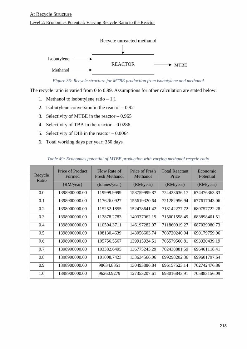
218
At Recycle Structure
Level 2: Economics Potential: Varying Recycle Ratio to the Reactor
Recycle unreacted methanol
Figure 35: Recycle structure for MTBE production from isobutylene and methanol
The recycle ratio is varied from 0 to 0.99. Assumptions for other calculation are stated below:
1. Methanol to isobutylene ratio – 1.1
2. Isobutylene conversion in the reactor – 0.92
3. Selectivity of MTBE in the reactor – 0.965
4. Selectivity of TBA in the reactor – 0.0286
5. Selectivity of DIB in the reactor – 0.0064
6. Total working days per year: 350 days
Table 49: Economics potential of MTBE production with varying methanol recycle ratio
Recycle
Ratio
Price of Product
Formed
Flow Rate of
Fresh Methanol
Price of Fresh
Methanol
Total Reactant
Price
Economic
Potential
(RM/year) (tonnes/year) (RM/year) (RM/year) (RM/year)
0.0 1398900000.00 119999.9999 158759999.87 724423636.17 674476363.83
0.1 1398900000.00 117626.0927 155619320.64 721282956.94 677617043.06
0.2 1398900000.00 115252.1855 152478641.42 718142277.72 680757722.28
0.3 1398900000.00 112878.2783 149337962.19 715001598.49 683898401.51
0.4 1398900000.00 110504.3711 146197282.97 711860919.27 687039080.73
0.5 1398900000.00 108130.4639 143056603.74 708720240.04 690179759.96
0.6 1398900000.00 105756.5567 139915924.51 705579560.81 693320439.19
0.7 1398900000.00 103382.6495 136775245.29 702438881.59 696461118.41
0.8 1398900000.00 101008.7423 133634566.06 699298202.36 699601797.64
0.9 1398900000.00 98634.8351 130493886.84 696157523.14 702742476.86
1.0 1398900000.00 96260.9279 127353207.61 693016843.91 705883156.09
REACTOR Isobutylene
MTBE Methanol
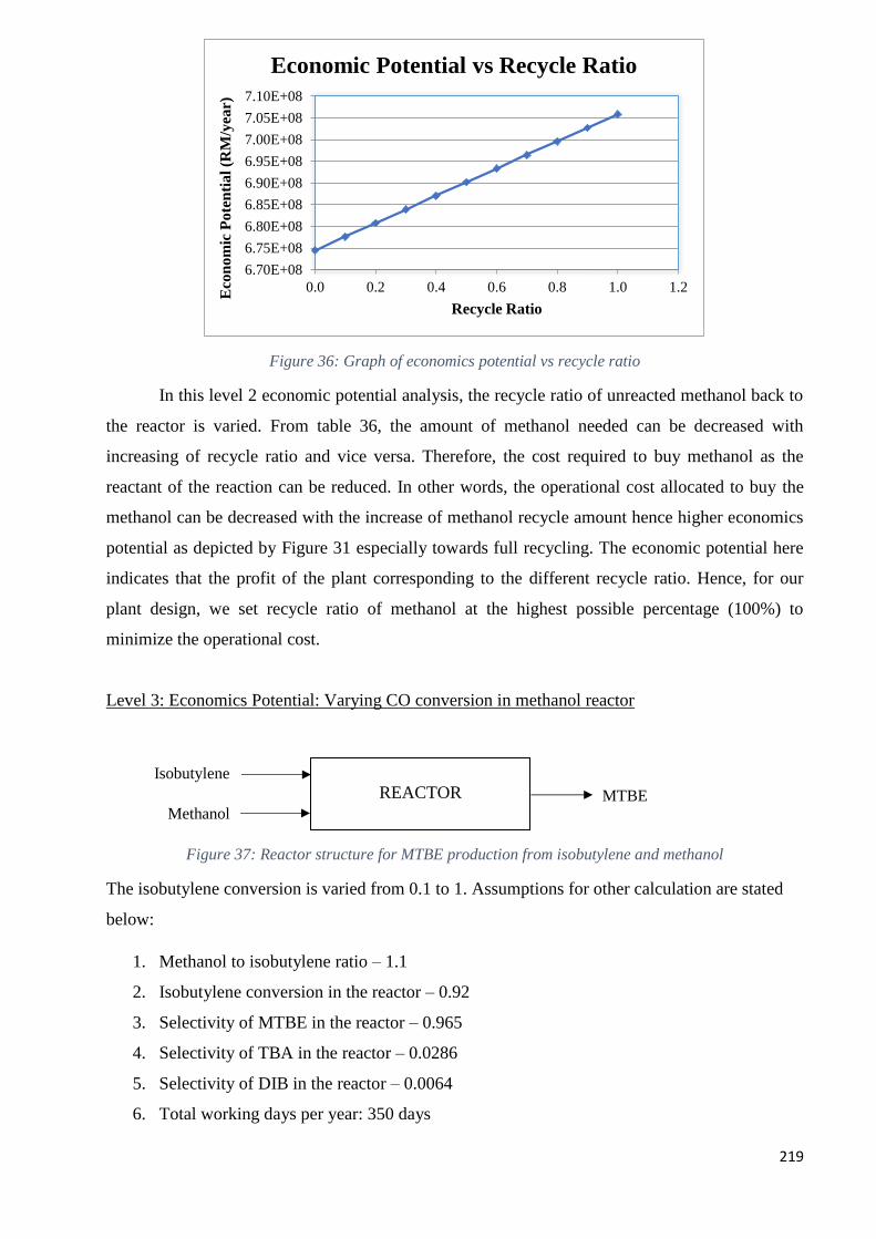
219
Figure 36: Graph of economics potential vs recycle ratio
In this level 2 economic potential analysis, the recycle ratio of unreacted methanol back to
the reactor is varied. From table 36, the amount of methanol needed can be decreased with
increasing of recycle ratio and vice versa. Therefore, the cost required to buy methanol as the
reactant of the reaction can be reduced. In other words, the operational cost allocated to buy the
methanol can be decreased with the increase of methanol recycle amount hence higher economics
potential as depicted by Figure 31 especially towards full recycling. The economic potential here
indicates that the profit of the plant corresponding to the different recycle ratio. Hence, for our
plant design, we set recycle ratio of methanol at the highest possible percentage (100%) to
minimize the operational cost.
Level 3: Economics Potential: Varying CO conversion in methanol reactor
Figure 37: Reactor structure for MTBE production from isobutylene and methanol
The isobutylene conversion is varied from 0.1 to 1. Assumptions for other calculation are stated
below:
1. Methanol to isobutylene ratio – 1.1
2. Isobutylene conversion in the reactor – 0.92
3. Selectivity of MTBE in the reactor – 0.965
4. Selectivity of TBA in the reactor – 0.0286
5. Selectivity of DIB in the reactor – 0.0064
6. Total working days per year: 350 days
6.70E+08
6.75E+08
6.80E+08
6.85E+08
6.90E+08
6.95E+08
7.00E+08
7.05E+08
7.10E+08
0.0 0.2 0.4 0.6 0.8 1.0 1.2
Eco
no
mic
Po
ten
tia
l (R
M/y
ear)
Recycle Ratio
Economic Potential vs Recycle Ratio
REACTOR Isobutylene
MTBE Methanol
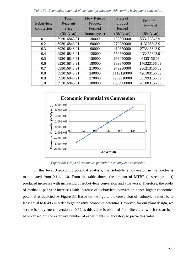
220
Table 50: Economics potential of methanol production with varying isobutylene conversion
Isobutylene
conversion
Total
Reactant
Price
Flow Rate of
Product
Formed
Price of
product
formed
Economic
Potential
(RM/year) (tonnes/year) (RM/year) (RM/year)
0.1 693016843.91 30000 139890000 -553126843.91
0.2 693016843.91 60000 279780000 -413236843.91
0.3 693016843.91 90000 419670000 -273346843.91
0.4 693016843.91 120000 559560000 -133456843.91
0.5 693016843.91 150000 699450000 6433156.09
0.6 693016843.91 180000 839340000 146323156.09
0.7 693016843.91 210000 979230000 286213156.09
0.8 693016843.91 240000 1119120000 426103156.09
0.9 693016843.91 270000 1259010000 565993156.09
1.0 693016843.91 300000 1398900000 705883156.09
Figure 38: Graph of economics potential vs isobutylene conversion
In this level 3 economic potential analysis, the isobutylene conversion in the reactor is
manipulated from 0.1 to 1.0. From the table above, the amount of MTBE (desired product)
produced increases with increasing of isobutylene conversion and vice versa. Therefore, the profit
of methanol per year increases with increase of isobutylene conversion hence higher economics
potential as depicted by Figure 33. Based on the figure, the conversion of isobutylene must be at
least equal to 0.495 in order to get positive economic potential. However, for our plant design, we
set the isobutylene conversion at 0.92 as this value is obtained from literature, which researchers
have carried out the extensive number of experiments in laboratory to prove this value.
-8.00E+08
-6.00E+08
-4.00E+08
-2.00E+08
0.00E+00
2.00E+08
4.00E+08
6.00E+08
8.00E+08
0.0 0.2 0.4 0.6 0.8 1.0 1.2
Eco
nom
ic P
ote
nti
al
(RM
/yea
r)
Conversion
Economic Potential vs Conversion
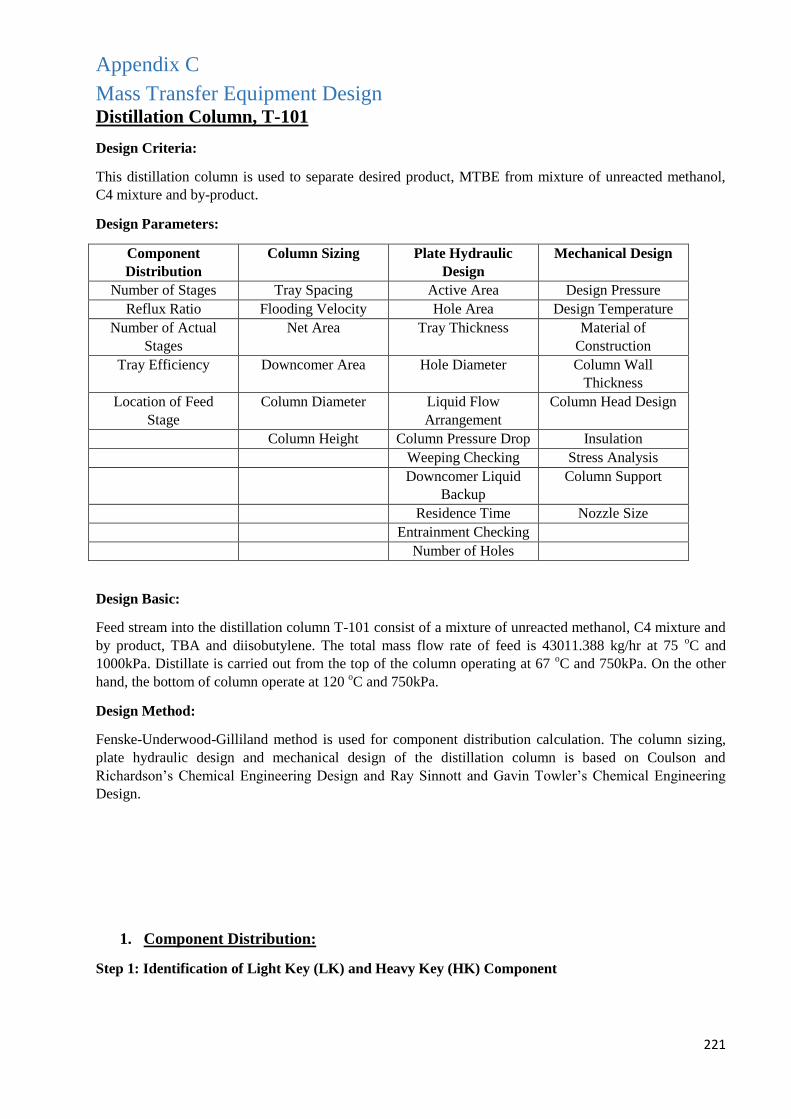
221
Appendix C
Mass Transfer Equipment Design Distillation Column, T-101
Design Criteria:
This distillation column is used to separate desired product, MTBE from mixture of unreacted methanol,
C4 mixture and by-product.
Design Parameters:
Component
Distribution
Column Sizing Plate Hydraulic
Design
Mechanical Design
Number of Stages Tray Spacing Active Area Design Pressure
Reflux Ratio Flooding Velocity Hole Area Design Temperature
Number of Actual
Stages
Net Area Tray Thickness Material of
Construction
Tray Efficiency Downcomer Area Hole Diameter Column Wall
Thickness
Location of Feed
Stage
Column Diameter Liquid Flow
Arrangement
Column Head Design
Column Height Column Pressure Drop Insulation
Weeping Checking Stress Analysis
Downcomer Liquid
Backup
Column Support
Residence Time Nozzle Size
Entrainment Checking
Number of Holes
Design Basic:
Feed stream into the distillation column T-101 consist of a mixture of unreacted methanol, C4 mixture and
by product, TBA and diisobutylene. The total mass flow rate of feed is 43011.388 kg/hr at 75 oC and
1000kPa. Distillate is carried out from the top of the column operating at 67 oC and 750kPa. On the other
hand, the bottom of column operate at 120 oC and 750kPa.
Design Method:
Fenske-Underwood-Gilliland method is used for component distribution calculation. The column sizing,
plate hydraulic design and mechanical design of the distillation column is based on Coulson and
Richardson’s Chemical Engineering Design and Ray Sinnott and Gavin Towler’s Chemical Engineering
Design.
1. Component Distribution:
Step 1: Identification of Light Key (LK) and Heavy Key (HK) Component
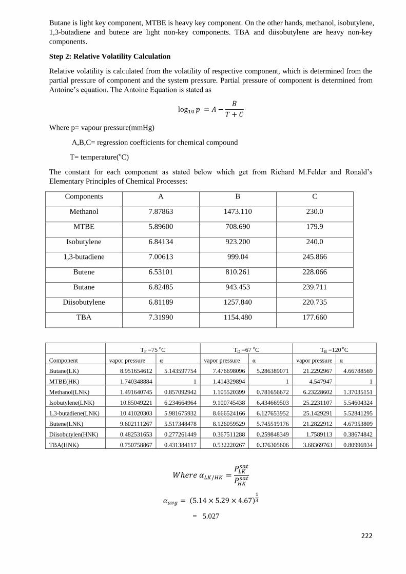
222
Butane is light key component, MTBE is heavy key component. On the other hands, methanol, isobutylene,
1,3-butadiene and butene are light non-key components. TBA and diisobutylene are heavy non-key
components.
Step 2: Relative Volatility Calculation
Relative volatility is calculated from the volatility of respective component, which is determined from the
partial pressure of component and the system pressure. Partial pressure of component is determined from
Antoine’s equation. The Antoine Equation is stated as
log10 𝑝 = 𝐴 −𝐵
𝑇 + 𝐶
Where p= vapour pressure(mmHg)
A,B,C= regression coefficients for chemical compound
T= temperature(oC)
The constant for each component as stated below which get from Richard M.Felder and Ronald’s
Elementary Principles of Chemical Processes:
Components A B C
Methanol 7.87863 1473.110 230.0
MTBE 5.89600 708.690 179.9
Isobutylene 6.84134 923.200 240.0
1,3-butadiene 7.00613 999.04 245.866
Butene 6.53101 810.261 228.066
Butane 6.82485 943.453 239.711
Diisobutylene 6.81189 1257.840 220.735
TBA 7.31990 1154.480 177.660
TF =75 oC TD =67 oC TB =120 oC
Component vapor pressure α vapor pressure α vapor pressure α
Butane(LK) 8.951654612 5.143597754 7.476698096 5.286389071 21.2292967 4.66788569
MTBE(HK) 1.740348884 1 1.414329894 1 4.547947 1
Methanol(LNK) 1.491640745 0.857092942 1.105520399 0.781656672 6.23228602 1.37035151
Isobutylene(LNK) 10.85049221 6.234664964 9.100745438 6.434669503 25.2231107 5.54604324
1,3-butadiene(LNK) 10.41020303 5.981675932 8.666524166 6.127653952 25.1429291 5.52841295
Butene(LNK) 9.602111267 5.517348478 8.126059529 5.745519176 21.2822912 4.67953809
Diisobutylen(HNK) 0.482531653 0.277261449 0.367511288 0.259848349 1.7589113 0.38674842
TBA(HNK) 0.750758867 0.431384117 0.532220267 0.376305606 3.68369763 0.80996934
𝑊ℎ𝑒𝑟𝑒 𝛼𝐿𝐾/𝐻𝐾 =𝑃𝐿𝐾
𝑠𝑎𝑡
𝑃𝐻𝐾𝑠𝑎𝑡
𝛼𝑎𝑣𝑔 = (5.14 × 5.29 × 4.67)13
= 5.027
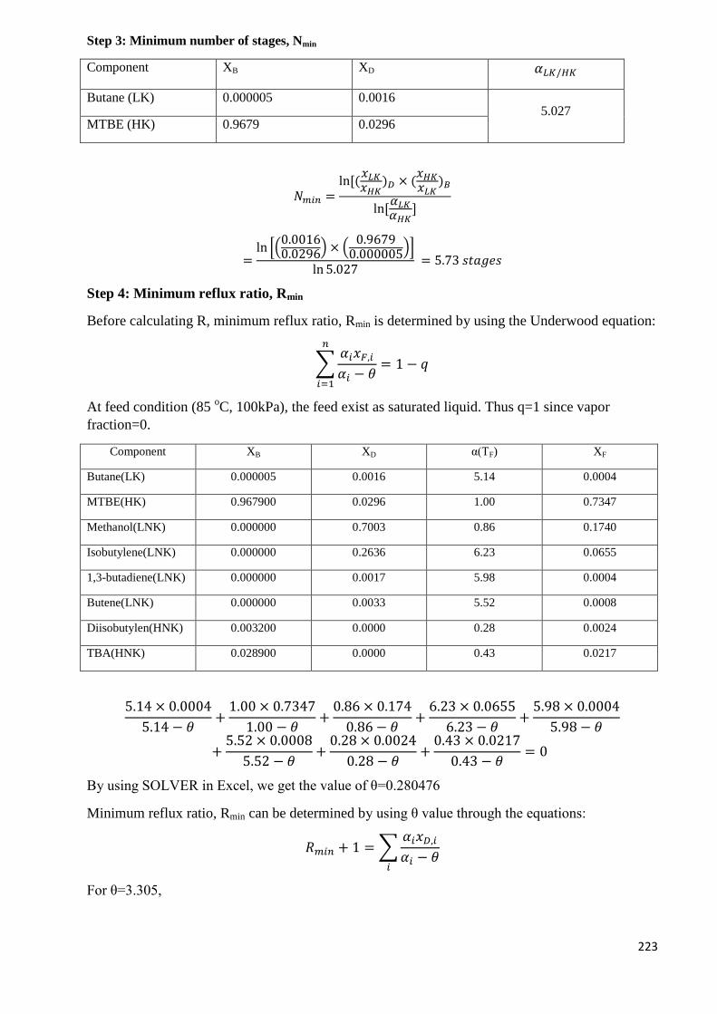
223
Step 3: Minimum number of stages, Nmin
Component XB XD 𝛼𝐿𝐾/𝐻𝐾
Butane (LK) 0.000005 0.0016 5.027
MTBE (HK) 0.9679 0.0296
𝑁𝑚𝑖𝑛 =ln[(
𝑥𝐿𝐾𝑥𝐻𝐾
)𝐷 × (𝑥𝐻𝐾𝑥𝐿𝐾
)𝐵
ln[𝛼𝐿𝐾𝛼𝐻𝐾
]
=ln [(
0.00160.0296
) × (0.9679
0.000005)]
ln 5.027 = 5.73 𝑠𝑡𝑎𝑔𝑒𝑠
Step 4: Minimum reflux ratio, Rmin
Before calculating R, minimum reflux ratio, Rmin is determined by using the Underwood equation:
∑𝛼𝑖𝑥𝐹,𝑖
𝛼𝑖 − 𝜃= 1 − 𝑞
𝑛
𝑖=1
At feed condition (85 oC, 100kPa), the feed exist as saturated liquid. Thus q=1 since vapor
fraction=0.
Component XB XD α(TF) XF
Butane(LK) 0.000005 0.0016 5.14 0.0004
MTBE(HK) 0.967900 0.0296 1.00 0.7347
Methanol(LNK) 0.000000 0.7003 0.86 0.1740
Isobutylene(LNK) 0.000000 0.2636 6.23 0.0655
1,3-butadiene(LNK) 0.000000 0.0017 5.98 0.0004
Butene(LNK) 0.000000 0.0033 5.52 0.0008
Diisobutylen(HNK) 0.003200 0.0000 0.28 0.0024
TBA(HNK) 0.028900 0.0000 0.43 0.0217
5.14 × 0.0004
5.14 − 𝜃+
1.00 × 0.7347
1.00 − 𝜃+
0.86 × 0.174
0.86 − 𝜃+
6.23 × 0.0655
6.23 − 𝜃+
5.98 × 0.0004
5.98 − 𝜃
+5.52 × 0.0008
5.52 − 𝜃+
0.28 × 0.0024
0.28 − 𝜃+
0.43 × 0.0217
0.43 − 𝜃= 0
By using SOLVER in Excel, we get the value of θ=0.280476
Minimum reflux ratio, Rmin can be determined by using θ value through the equations:
𝑅𝑚𝑖𝑛 + 1 = ∑𝛼𝑖𝑥𝐷,𝑖
𝛼𝑖 − 𝜃𝑖
For θ=3.305,
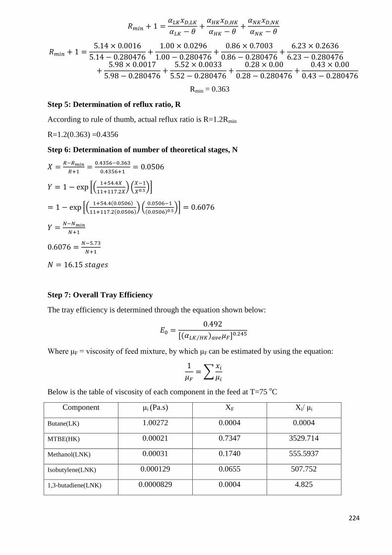
224
𝑅𝑚𝑖𝑛 + 1 =𝛼𝐿𝐾𝑥𝐷,𝐿𝐾
𝛼𝐿𝐾 − 𝜃+
𝛼𝐻𝐾𝑥𝐷,𝐻𝐾
𝛼𝐻𝐾 − 𝜃+
𝛼𝑁𝐾𝑥𝐷,𝑁𝐾
𝛼𝑁𝐾 − 𝜃
𝑅𝑚𝑖𝑛 + 1 =5.14 × 0.0016
5.14 − 0.280476+
1.00 × 0.0296
1.00 − 0.280476+
0.86 × 0.7003
0.86 − 0.280476+
6.23 × 0.2636
6.23 − 0.280476
+5.98 × 0.0017
5.98 − 0.280476+
5.52 × 0.0033
5.52 − 0.280476+
0.28 × 0.00
0.28 − 0.280476+
0.43 × 0.00
0.43 − 0.280476
Rmin = 0.363
Step 5: Determination of reflux ratio, R
According to rule of thumb, actual reflux ratio is R=1.2Rmin
R=1.2(0.363) =0.4356
Step 6: Determination of number of theoretical stages, N
𝑋 =𝑅−𝑅𝑚𝑖𝑛
𝑅+1=
0.4356−0.363
0.4356+1= 0.0506
𝑌 = 1 − exp [(1+54.4𝑋
11+117.2𝑋) (
𝑋−1
𝑋0.5)]
= 1 − exp [(1+54.4(0.0506)
11+117.2(0.0506)) (
0.0506−1
(0.0506)0.5)] = 0.6076
𝑌 =𝑁−𝑁𝑚𝑖𝑛
𝑁+1
0.6076 =𝑁−5.73
𝑁+1
𝑁 = 16.15 𝑠𝑡𝑎𝑔𝑒𝑠
Step 7: Overall Tray Efficiency
The tray efficiency is determined through the equation shown below:
𝐸0 =0.492
[(𝛼𝐿𝐾 𝐻𝐾⁄ )𝑎𝑣𝑒𝜇𝐹]0.245
Where μF = viscosity of feed mixture, by which μF can be estimated by using the equation:
1
𝜇𝐹= ∑
𝑥𝑖
𝜇𝑖
Below is the table of viscosity of each component in the feed at T=75 oC
Component μi (Pa.s) XF Xi/ μi
Butane(LK) 1.00272 0.0004 0.0004
MTBE(HK) 0.00021 0.7347 3529.714
Methanol(LNK) 0.00031 0.1740 555.5937
Isobutylene(LNK) 0.000129 0.0655 507.752
1,3-butadiene(LNK) 0.0000829 0.0004 4.825
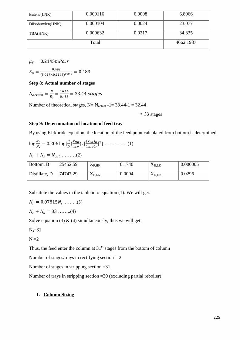
225
Butene(LNK) 0.000116 0.0008 6.8966
Diisobutylen(HNK) 0.000104 0.0024 23.077
TBA(HNK) 0.000632 0.0217 34.335
Total 4662.1937
𝜇𝐹 = 0.2145𝑚𝑃𝑎. 𝑠
𝐸0 =0.492
(5.027×0.2145)0.245 = 0.483
Step 8: Actual number of stages
𝑁𝑎𝑐𝑡𝑢𝑎𝑙 =𝑁
𝐸0=
16.15
0.483= 33.44 𝑠𝑡𝑎𝑔𝑒𝑠
Number of theoretical stages, N= Nactual -1= 33.44-1 = 32.44
≈ 33 stages
Step 9: Determination of location of feed tray
By using Kirkbride equation, the location of the feed point calculated from bottom is determined.
log𝑁𝑟
𝑁𝑠= 0.206 log{
𝐵
𝐷(𝑥𝐻𝐾
𝑥𝐿𝐾)𝐹[
(𝑥𝐿𝐾)𝐵
(𝑥𝐻𝐾)𝐷]2} ………….. (1)
𝑁𝑟 + 𝑁𝑠 = 𝑁𝑎𝑐𝑡 ………(2)
Bottom, B 25452.59 XF,HK 0.1740 XB,LK 0.000005
Distillate, D 74747.29 XF,LK 0.0004 XD,HK 0.0296
Subsitute the values in the table into equation (1). We will get:
𝑁𝑟 = 0.07815𝑁𝑠 ……..(3)
𝑁𝑟 + 𝑁𝑠 = 33 ……..(4)
Solve equation (3) & (4) simultaneously, thus we will get:
Ns=31
Nr=2
Thus, the feed enter the column at 31st stages from the bottom of column
Number of stages/trays in rectifying section = 2
Number of stages in stripping section =31
Number of trays in stripping section =30 (excluding partial reboiler)
1. Column Sizing
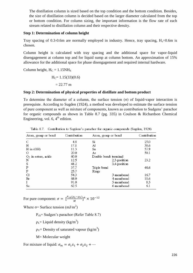
226
The distillation column is sized based on the top condition and the bottom condition. Besides,
the size of distillation column is decided based on the larger diameter calculated from the top
or bottom condition. For column sizing, the important information is the flow rate of each
stream related to distillation column and their respective density.
Step 1: Determination of column height
Tray spacing of 0.3-0.6m are normally employed in industry. Hence, tray spacing, Hs=0.6m is
chosen.
Column height is calculated with tray spacing and the additional space for vapor-liquid
disengagement at column top and for liquid sump at column bottom. An approximation of 15%
allowance for the additional space for phase disengagement and required internal hardware.
Column height, HC = 1.15NHS
HC= 1.15(33)(0.6)
= 22.77 m
Step 2: Determination of physical properties of distillate and bottom product
To determine the diameter of a column, the surface tension (σ) of liquid-vapor interaction is
prerequiste. According to Sugden (1924), a method was developed to estimate the surface tension
of pure component as well as mixture of components, known as contribution to Sudgens’ parachor
for organic compounds as shown in Table 8.7 (pg. 335) in Coulson & Richardson Chemical
Engineering, vol. 6, 4th
edition.
For pure component: 𝜎 = [𝑃𝑐ℎ(𝜌𝐿−𝜌𝑉)
𝑀]4 × 10⁻¹²
Where σ= Surface tension (mJ/m2)
Pch= Sudgen’s parachor (Refer Table 8.7)
ρL= Liquid density (kg/m3)
ρV= Density of saturated vapour (kg/m3)
M= Molecular weight
For mixture of liquid: 𝜎𝑚 = 𝜎1𝑥1 + 𝜎2𝑥2 + ⋯
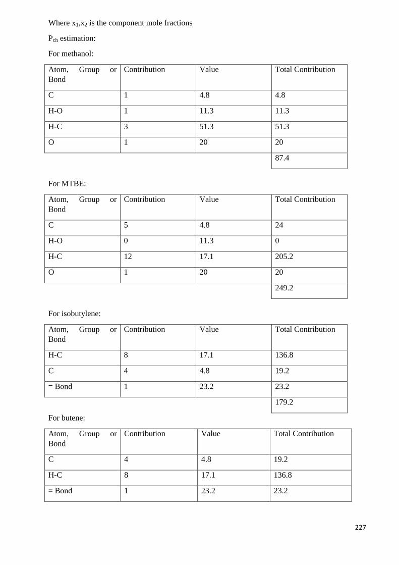
227
Where x1,x2 is the component mole fractions
Pch estimation:
For methanol:
Atom, Group or
Bond
Contribution Value Total Contribution
C 1 4.8 4.8
H-O 1 11.3 11.3
H-C 3 51.3 51.3
O 1 20 20
87.4
For MTBE:
Atom, Group or
Bond
Contribution Value Total Contribution
C 5 4.8 24
H-O 0 11.3 0
H-C 12 17.1 205.2
O 1 20 20
249.2
For isobutylene:
Atom, Group or
Bond
Contribution Value Total Contribution
H-C 8 17.1 136.8
C 4 4.8 19.2
= Bond 1 23.2 23.2
179.2
For butene:
Atom, Group or
Bond
Contribution Value Total Contribution
C 4 4.8 19.2
H-C 8 17.1 136.8
= Bond 1 23.2 23.2
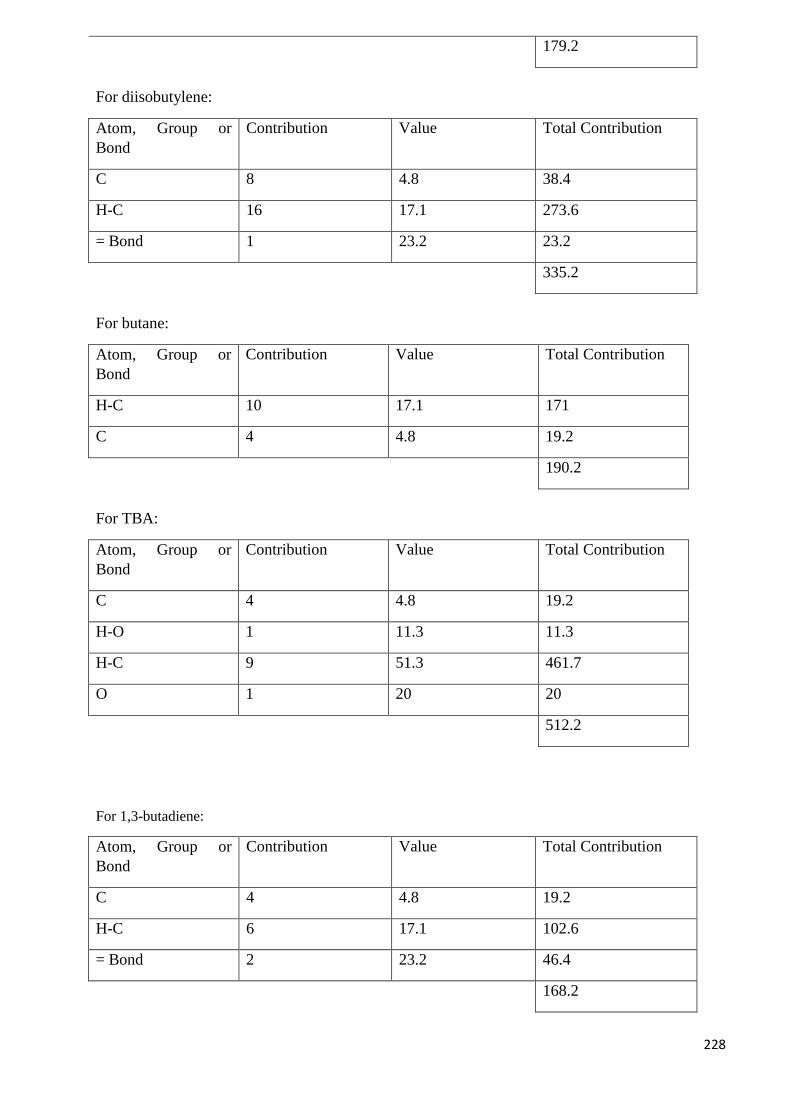
228
179.2
For diisobutylene:
Atom, Group or
Bond
Contribution Value Total Contribution
C 8 4.8 38.4
H-C 16 17.1 273.6
= Bond 1 23.2 23.2
335.2
For butane:
Atom, Group or
Bond
Contribution Value Total Contribution
H-C 10 17.1 171
C 4 4.8 19.2
190.2
For TBA:
Atom, Group or
Bond
Contribution Value Total Contribution
C 4 4.8 19.2
H-O 1 11.3 11.3
H-C 9 51.3 461.7
O 1 20 20
512.2
For 1,3-butadiene:
Atom, Group or
Bond
Contribution Value Total Contribution
C 4 4.8 19.2
H-C 6 17.1 102.6
= Bond 2 23.2 46.4
168.2
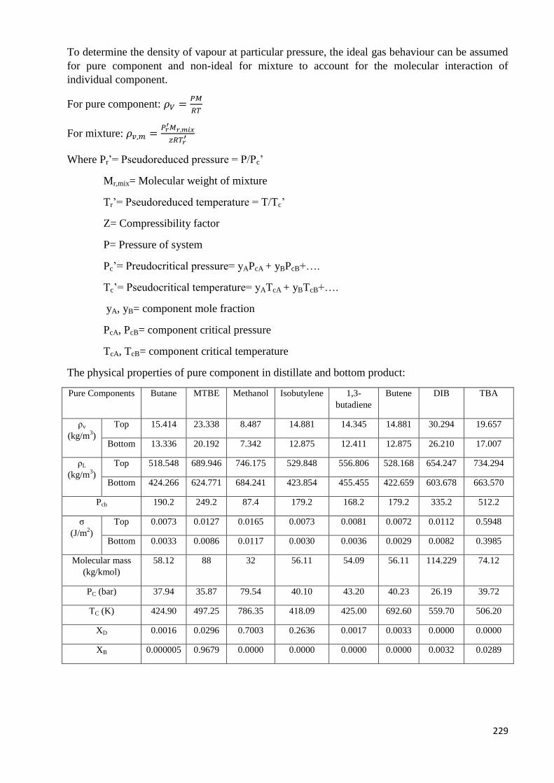
229
To determine the density of vapour at particular pressure, the ideal gas behaviour can be assumed
for pure component and non-ideal for mixture to account for the molecular interaction of
individual component.
For pure component: 𝜌𝑉 =𝑃𝑀
𝑅𝑇
For mixture: 𝜌𝑣,𝑚 =𝑃𝑟
′𝑀𝑟,𝑚𝑖𝑥
𝑧𝑅𝑇𝑟′
Where Pr’= Pseudoreduced pressure = P/Pc’
Mr,mix= Molecular weight of mixture
Tr’= Pseudoreduced temperature = T/Tc’
Z= Compressibility factor
P= Pressure of system
Pc’= Preudocritical pressure= yAPcA + yBPcB+….
Tc’= Pseudocritical temperature= yATcA + yBTcB+….
yA, yB= component mole fraction
PcA, PcB= component critical pressure
TcA, TcB= component critical temperature
The physical properties of pure component in distillate and bottom product:
Pure Components Butane MTBE Methanol Isobutylene 1,3-
butadiene
Butene DIB TBA
ρv
(kg/m3)
Top 15.414 23.338 8.487 14.881 14.345 14.881 30.294 19.657
Bottom 13.336 20.192 7.342 12.875 12.411 12.875 26.210 17.007
ρL
(kg/m3)
Top 518.548 689.946 746.175 529.848 556.806 528.168 654.247 734.294
Bottom 424.266 624.771 684.241 423.854 455.455 422.659 603.678 663.570
Pch 190.2 249.2 87.4 179.2 168.2 179.2 335.2 512.2
σ
(J/m2)
Top 0.0073 0.0127 0.0165 0.0073 0.0081 0.0072 0.0112 0.5948
Bottom 0.0033 0.0086 0.0117 0.0030 0.0036 0.0029 0.0082 0.3985
Molecular mass
(kg/kmol)
58.12 88 32 56.11 54.09 56.11 114.229 74.12
PC (bar) 37.94 35.87 79.54 40.10 43.20 40.23 26.19 39.72
TC (K) 424.90 497.25 786.35 418.09 425.00 692.60 559.70 506.20
XD 0.0016 0.0296 0.7003 0.2636 0.0017 0.0033 0.0000 0.0000
XB 0.000005 0.9679 0.0000 0.0000 0.0000 0.0000 0.0032 0.0289
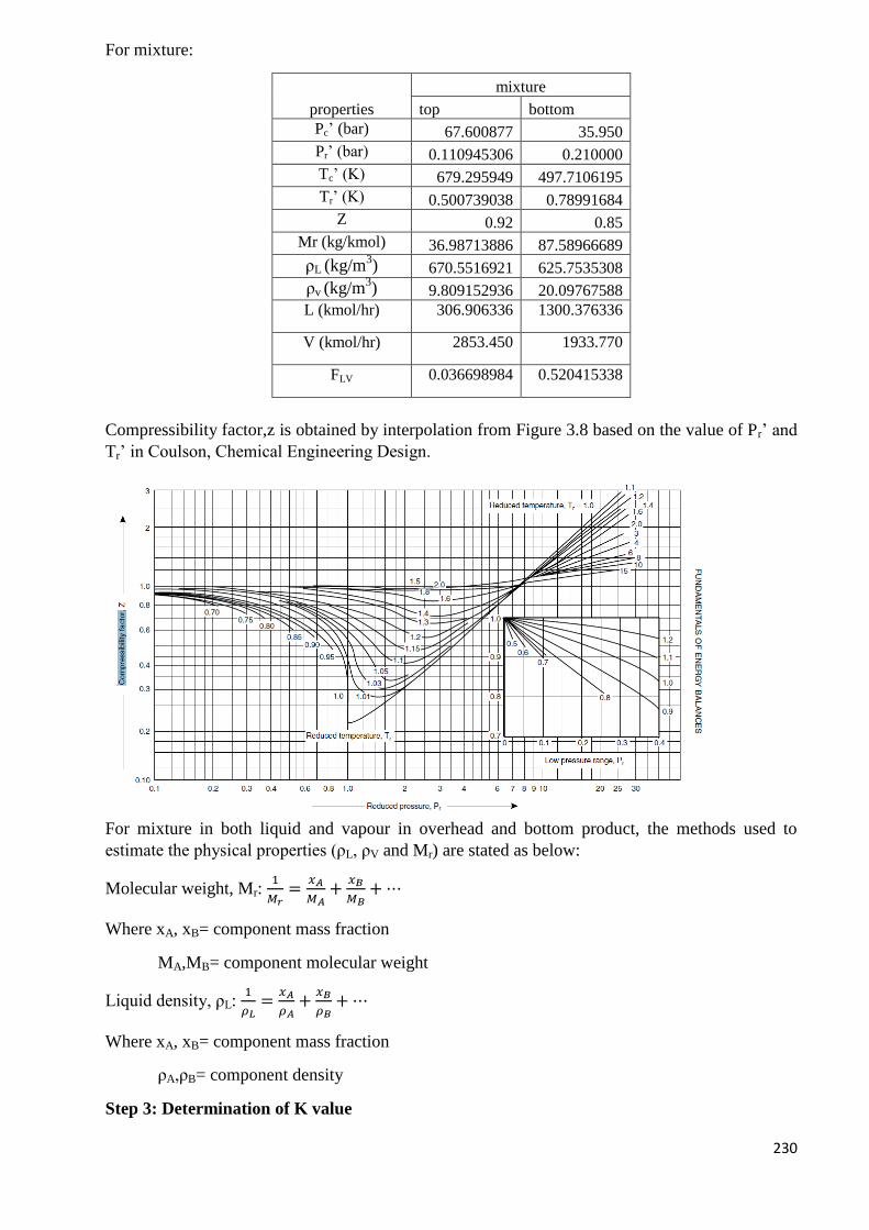
230
For mixture:
properties
mixture
top bottom
Pc’ (bar) 67.600877 35.950
Pr’ (bar) 0.110945306 0.210000
Tc’ (K) 679.295949 497.7106195
Tr’ (K) 0.500739038 0.78991684
Z 0.92 0.85
Mr (kg/kmol) 36.98713886 87.58966689
ρL (kg/m3) 670.5516921 625.7535308
ρv (kg/m3) 9.809152936 20.09767588
L (kmol/hr) 306.906336 1300.376336
V (kmol/hr) 2853.450 1933.770
FLV 0.036698984 0.520415338
Compressibility factor,z is obtained by interpolation from Figure 3.8 based on the value of Pr’ and
Tr’ in Coulson, Chemical Engineering Design.
For mixture in both liquid and vapour in overhead and bottom product, the methods used to
estimate the physical properties (ρL, ρV and Mr) are stated as below:
Molecular weight, Mr: 1
𝑀𝑟=
𝑥𝐴
𝑀𝐴+
𝑥𝐵
𝑀𝐵+ ⋯
Where xA, xB= component mass fraction
MA,MB= component molecular weight
Liquid density, ρL: 1
𝜌𝐿=
𝑥𝐴
𝜌𝐴+
𝑥𝐵
𝜌𝐵+ ⋯
Where xA, xB= component mass fraction
ρA,ρB= component density
Step 3: Determination of K value
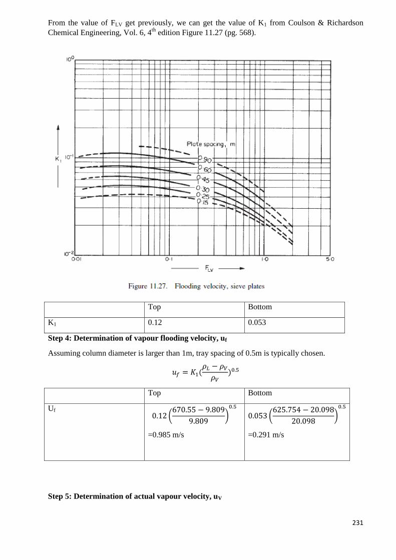
231
From the value of FLV get previously, we can get the value of K1 from Coulson & Richardson
Chemical Engineering, Vol. 6, 4th
edition Figure 11.27 (pg. 568).
Top Bottom
K1 0.12 0.053
Step 4: Determination of vapour flooding velocity, uf
Assuming column diameter is larger than 1m, tray spacing of 0.5m is typically chosen.
𝑢𝑓 = 𝐾1(𝜌𝐿 − 𝜌𝑉
𝜌𝑉)0.5
Top Bottom
Uf
0.12 (670.55 − 9.809
9.809)0.5
=0.985 m/s
0.053 (625.754 − 20.098
20.098)
0.5
=0.291 m/s
Step 5: Determination of actual vapour velocity, uV

232
Assume 50% flooding for column operation
𝑢𝑉 = 0.5𝑢𝑓
Top Bottom
UV 0.5(0.985 m/s)= 0.493 m/s 0.5(0.291 m/s)= 0.146 m/s
Step 6: Determination of volumetric flow rate, �̇�
�̇� =𝑣 (
𝑘𝑚𝑜𝑙ℎ𝑟
) × 𝑀𝑟 (𝑘𝑔
𝑘𝑚𝑜𝑙)
𝜌𝑉 (𝑘𝑔𝑚3) ×
3600𝑠ℎ𝑟
Top Bottom
�̇� 2853.45×36.987
9.809×3600
=2.99 m3/s
1933.77×87.59
20.098×3600
=2.34 m3/s
Step 7: Determination of net column area, An
𝐴𝑛 =�̇�
𝑢𝑣
Top Bottom
An 2.99/0.493
=6.06 m2
2.34/0.146
=16.03 m2
Step 8: Determination of cross sectional area, Ac
Assume downcomer occupies 20% of column cross sectional area, 𝐴𝑐 =𝐴𝑛
0.8
Top Bottom
Ac 6.06/0.8
=7.58 m2
16.03/0.8
=20.04 m2
Step 9: Determination of cross sectional area of downcomer, Ad
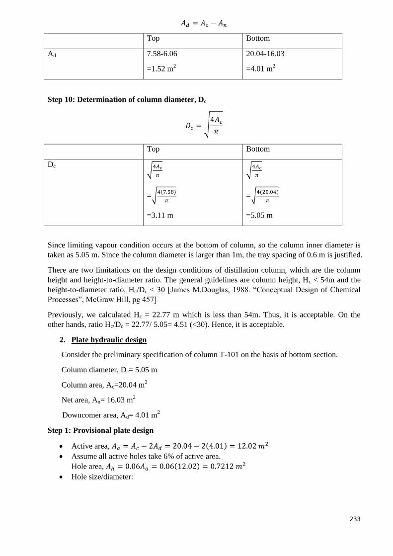
233
𝐴𝑑 = 𝐴𝑐 − 𝐴𝑛
Top Bottom
Ad 7.58-6.06
=1.52 m2
20.04-16.03
=4.01 m2
Step 10: Determination of column diameter, Dc
𝐷𝑐 = √4𝐴𝑐
𝜋
Top Bottom
Dc √
4𝐴𝑐
𝜋
=√4(7.58)
𝜋
=3.11 m
√4𝐴𝑐
𝜋
=√4(20.04)
𝜋
=5.05 m
Since limiting vapour condition occurs at the bottom of column, so the column inner diameter is
taken as 5.05 m. Since the column diameter is larger than 1m, the tray spacing of 0.6 m is justified.
There are two limitations on the design conditions of distillation column, which are the column
height and height-to-diameter ratio. The general guidelines are column height, Hc < 54m and the
height-to-diameter ratio, Hc/Dc < 30 [James M.Douglas, 1988. “Conceptual Design of Chemical
Processes”, McGraw Hill, pg 457]
Previously, we calculated Hc = 22.77 m which is less than 54m. Thus, it is acceptable. On the
other hands, ratio Hc/Dc = 22.77/ 5.05= 4.51 (<30). Hence, it is acceptable.
2. Plate hydraulic design
Consider the preliminary specification of column T-101 on the basis of bottom section.
Column diameter, Dc= 5.05 m
Column area, Ac=20.04 m2
Net area, An= 16.03 m2
Downcomer area, Ad= 4.01 m
2
Step 1: Provisional plate design
Active area, 𝐴𝑎 = 𝐴𝑐 − 2𝐴𝑑 = 20.04 − 2(4.01) = 12.02 𝑚2
Assume all active holes take 6% of active area.
Hole area, 𝐴ℎ = 0.06𝐴𝑎 = 0.06(12.02) = 0.7212 𝑚2
Hole size/diameter:
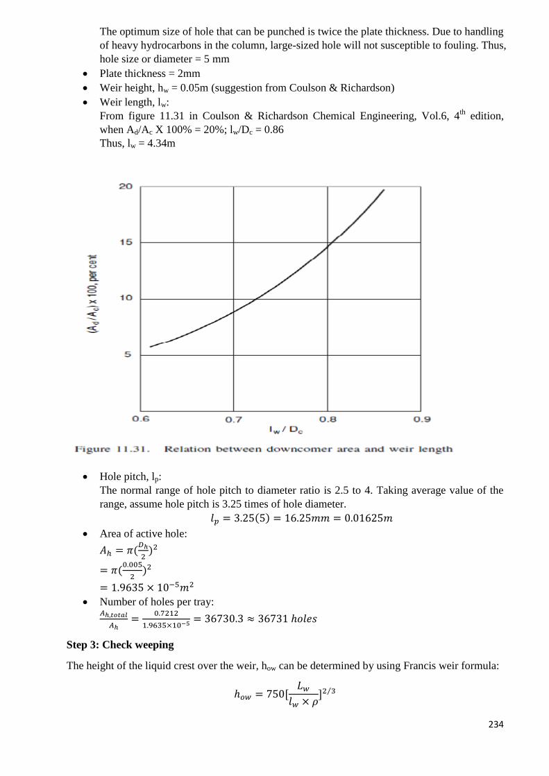
234
The optimum size of hole that can be punched is twice the plate thickness. Due to handling
of heavy hydrocarbons in the column, large-sized hole will not susceptible to fouling. Thus,
hole size or diameter = 5 mm
Plate thickness = 2mm
Weir height, hw = 0.05m (suggestion from Coulson & Richardson)
Weir length, lw:
From figure 11.31 in Coulson & Richardson Chemical Engineering, Vol.6, 4th
edition,
when Ad/Ac X 100% = 20%; lw/Dc = 0.86
Thus, lw = 4.34m
Hole pitch, lp:
The normal range of hole pitch to diameter ratio is 2.5 to 4. Taking average value of the
range, assume hole pitch is 3.25 times of hole diameter.
𝑙𝑝 = 3.25(5) = 16.25𝑚𝑚 = 0.01625𝑚
Area of active hole:
𝐴ℎ = 𝜋(𝐷ℎ
2)2
= 𝜋(0.005
2)2
= 1.9635 × 10⁻⁵𝑚2
Number of holes per tray: 𝐴ℎ,𝑡𝑜𝑡𝑎𝑙
𝐴ℎ=
0.7212
1.9635×10−5 = 36730.3 ≈ 36731 ℎ𝑜𝑙𝑒𝑠
Step 3: Check weeping
The height of the liquid crest over the weir, how can be determined by using Francis weir formula:
ℎ𝑜𝑤 = 750[𝐿𝑤
𝑙𝑤 × 𝜌]2 3⁄
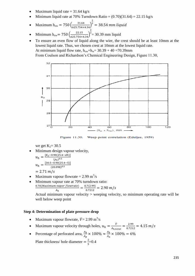
235
Maximum liquid rate = 31.64 kg/s
Minimum liquid rate at 70% Turndown Ratio = (0.70)(31.64) = 22.15 kg/s
Maximum how = 750 (31.64
625.754×4.34)
2
3= 38.54 𝑚𝑚 𝑙𝑖𝑞𝑢𝑖𝑑
Minimum how= 750 (22.15
625.754×4.34)
2
3= 30.39 mm liquid
To ensure an even flow of liquid along the wier, the crest should be at least 10mm at the
lowest liquid rate. Thus, we chosen crest at 10mm at the lowest liquid rate.
At minimum liquid flow rate, how+hw= 30.39 + 40 =70.39mm
From Coulson and Richardson’s Chemical Engineering Design, Figure 11.30,
we get K2= 30.5
Minimum design vapour velocity,
𝑢ℎ =[𝐾2−0.90(25.4−𝑑ℎ)]
(𝜌𝑣)0.5
𝑢ℎ =[30.5−0.90(25.4−5)]
(20.098)0.5
= 2.71 𝑚/𝑠
Maximum vapour flowrate = 2.99 m3/s
Minimum vapour rate at 70% turndown ratio: 0.70(𝑀𝑎𝑥𝑖𝑚𝑢𝑚 𝑣𝑎𝑝𝑜𝑟 𝑓𝑙𝑜𝑤𝑟𝑎𝑡𝑒)
𝐴ℎ=
0.7(2.99)
0.7212= 2.90 𝑚/𝑠
Actual minimum vapour velocity > weeping velocity, so minimum operating rate will be
well below weep point
Step 4: Determination of plate pressure drop
Maximum vapour flowrate, �̇�= 2.99 m3/s
Maximum vapour velocity through holes, 𝑢ℎ =�̇�
𝐴ℎ,𝑡𝑜𝑡𝑎𝑙=
2.99
0.7212= 4.15 𝑚/𝑠
Percentage of perforated area, 𝐴ℎ
𝐴𝑝× 100% ≈
𝐴ℎ
𝐴𝑎× 100% = 6%
Plate thickness/ hole diameter =2
5=0.4
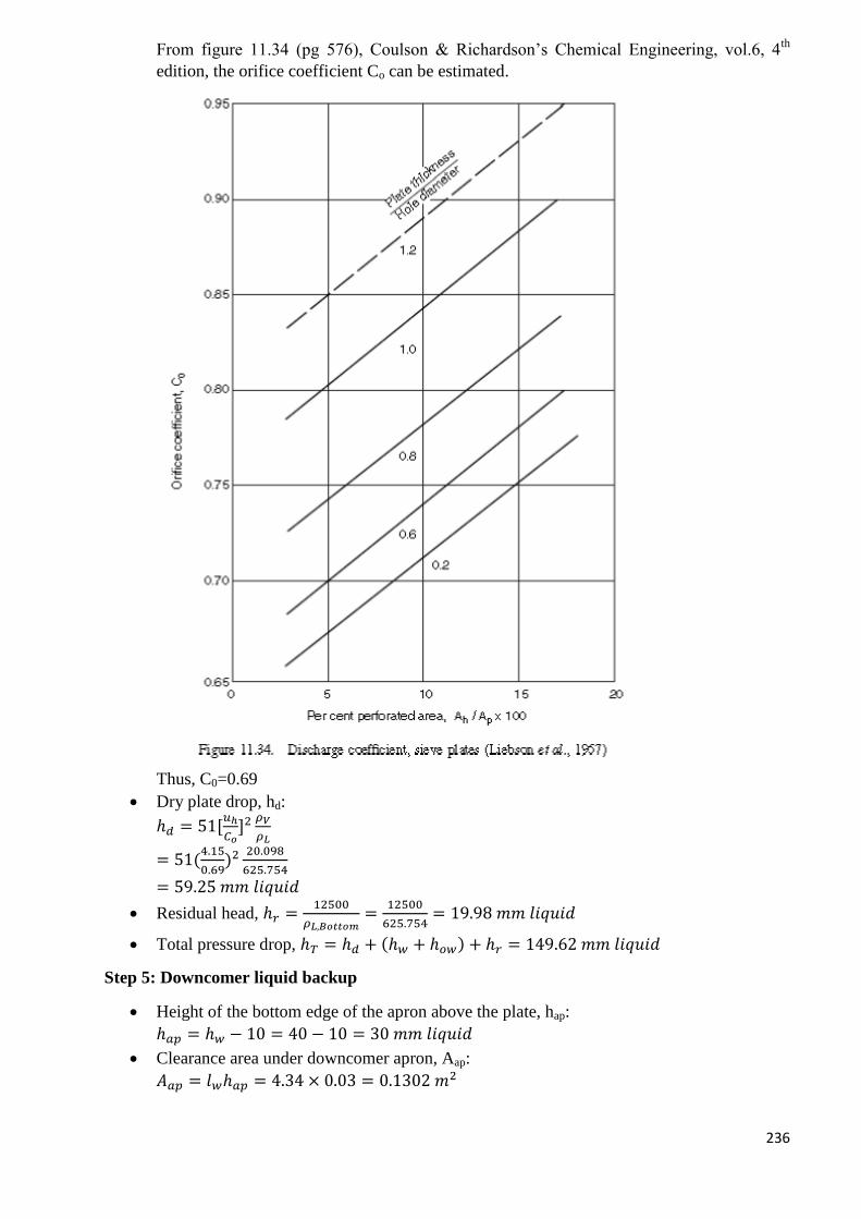
236
From figure 11.34 (pg 576), Coulson & Richardson’s Chemical Engineering, vol.6, 4th
edition, the orifice coefficient Co can be estimated.
Thus, C0=0.69
Dry plate drop, hd:
ℎ𝑑 = 51[𝑢ℎ
𝐶𝑜]2
𝜌𝑉
𝜌𝐿
= 51(4.15
0.69)2 20.098
625.754
= 59.25 𝑚𝑚 𝑙𝑖𝑞𝑢𝑖𝑑
Residual head, ℎ𝑟 =12500
𝜌𝐿,𝐵𝑜𝑡𝑡𝑜𝑚=
12500
625.754= 19.98 𝑚𝑚 𝑙𝑖𝑞𝑢𝑖𝑑
Total pressure drop, ℎ𝑇 = ℎ𝑑 + (ℎ𝑤 + ℎ𝑜𝑤) + ℎ𝑟 = 149.62 𝑚𝑚 𝑙𝑖𝑞𝑢𝑖𝑑
Step 5: Downcomer liquid backup
Height of the bottom edge of the apron above the plate, hap:
ℎ𝑎𝑝 = ℎ𝑤 − 10 = 40 − 10 = 30 𝑚𝑚 𝑙𝑖𝑞𝑢𝑖𝑑
Clearance area under downcomer apron, Aap:
𝐴𝑎𝑝 = 𝑙𝑤ℎ𝑎𝑝 = 4.34 × 0.03 = 0.1302 𝑚2
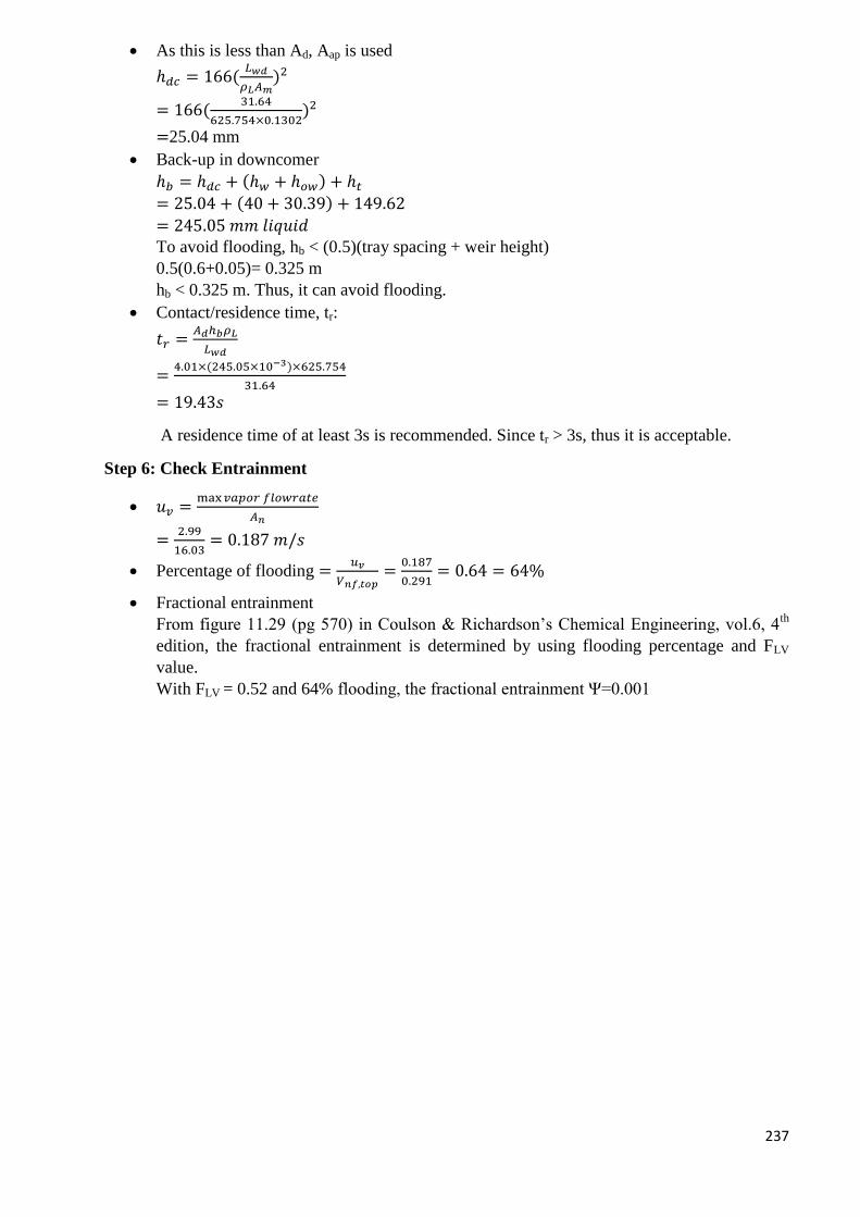
237
As this is less than Ad, Aap is used
ℎ𝑑𝑐 = 166(𝐿𝑤𝑑
𝜌𝐿𝐴𝑚)2
= 166(31.64
625.754×0.1302)2
=25.04 mm
Back-up in downcomer
ℎ𝑏 = ℎ𝑑𝑐 + (ℎ𝑤 + ℎ𝑜𝑤) + ℎ𝑡
= 25.04 + (40 + 30.39) + 149.62
= 245.05 𝑚𝑚 𝑙𝑖𝑞𝑢𝑖𝑑
To avoid flooding, hb < (0.5)(tray spacing + weir height)
0.5(0.6+0.05)= 0.325 m
hb < 0.325 m. Thus, it can avoid flooding.
Contact/residence time, tr:
𝑡𝑟 =𝐴𝑑ℎ𝑏𝜌𝐿
𝐿𝑤𝑑
=4.01×(245.05×10−3)×625.754
31.64
= 19.43𝑠
A residence time of at least 3s is recommended. Since tr > 3s, thus it is acceptable.
Step 6: Check Entrainment
𝑢𝑣 =max𝑣𝑎𝑝𝑜𝑟 𝑓𝑙𝑜𝑤𝑟𝑎𝑡𝑒
𝐴𝑛
=2.99
16.03= 0.187 𝑚/𝑠
Percentage of flooding =𝑢𝑣
𝑉𝑛𝑓,𝑡𝑜𝑝=
0.187
0.291= 0.64 = 64%
Fractional entrainment
From figure 11.29 (pg 570) in Coulson & Richardson’s Chemical Engineering, vol.6, 4th
edition, the fractional entrainment is determined by using flooding percentage and FLV
value.
With FLV = 0.52 and 64% flooding, the fractional entrainment Ψ=0.001
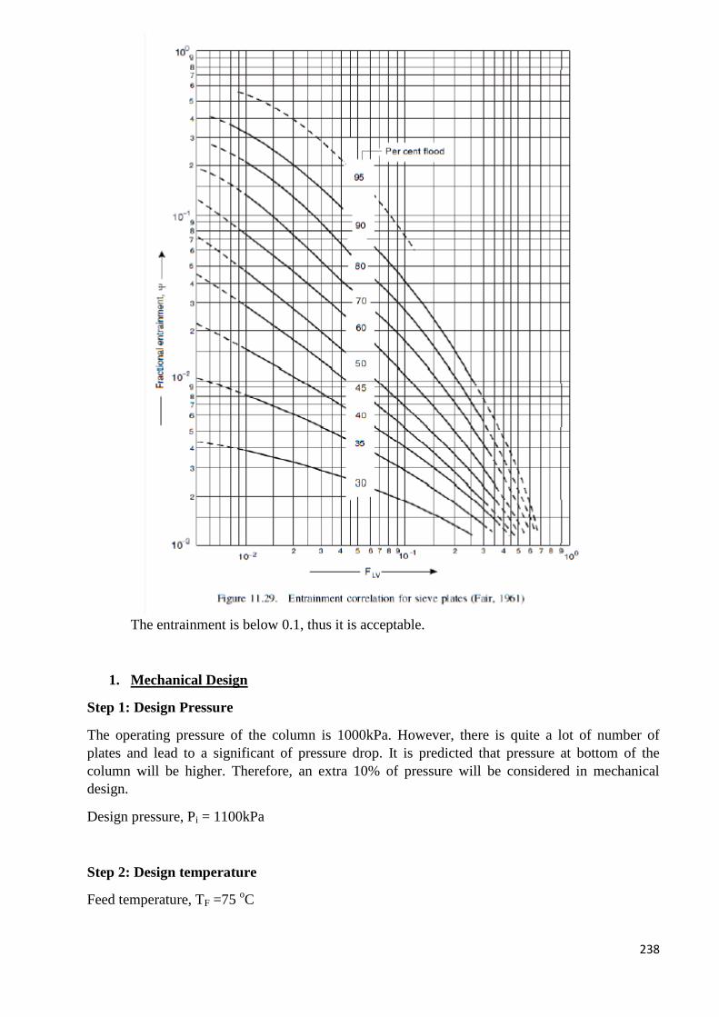
238
The entrainment is below 0.1, thus it is acceptable.
1. Mechanical Design
Step 1: Design Pressure
The operating pressure of the column is 1000kPa. However, there is quite a lot of number of
plates and lead to a significant of pressure drop. It is predicted that pressure at bottom of the
column will be higher. Therefore, an extra 10% of pressure will be considered in mechanical
design.
Design pressure, Pi = 1100kPa
Step 2: Design temperature
Feed temperature, TF =75 oC
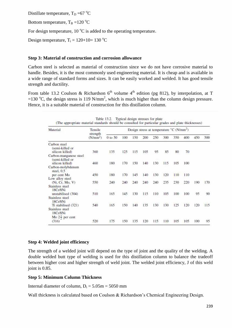
239
Distillate temperature, TD =67 oC
Bottom temperature, TB =120 oC
For design temperature, 10 oC is added to the operating temperature.
Design temperature, Ti = 120+10= 130 oC
Step 3: Material of construction and corrosion allowance
Carbon steel is selected as material of construction since we do not have corrosive material to
handle. Besides, it is the most commonly used engineering material. It is cheap and is available in
a wide range of standard forms and sizes. It can be easily worked and welded. It has good tensile
strength and ductility.
From table 13.2 Coulson & Richardson 6th
volume 4th
edition (pg 812), by interpolation, at T
=130 oC, the design stress is 119 N/mm
2, which is much higher than the column design pressure.
Hence, it is a suitable material of construction for this distillation column.
Step 4: Welded joint efficiency
The strength of a welded joint will depend on the type of joint and the quality of the welding. A
double welded butt type of welding is used for this distillation column to balance the tradeoff
between higher cost and higher strength of weld joint. The welded joint efficiency, J of this weld
joint is 0.85.
Step 5: Minimum Column Thickness
Internal diameter of column, Di = 5.05m = 5050 mm
Wall thickness is calculated based on Coulson & Richardson’s Chemical Engineering Design.
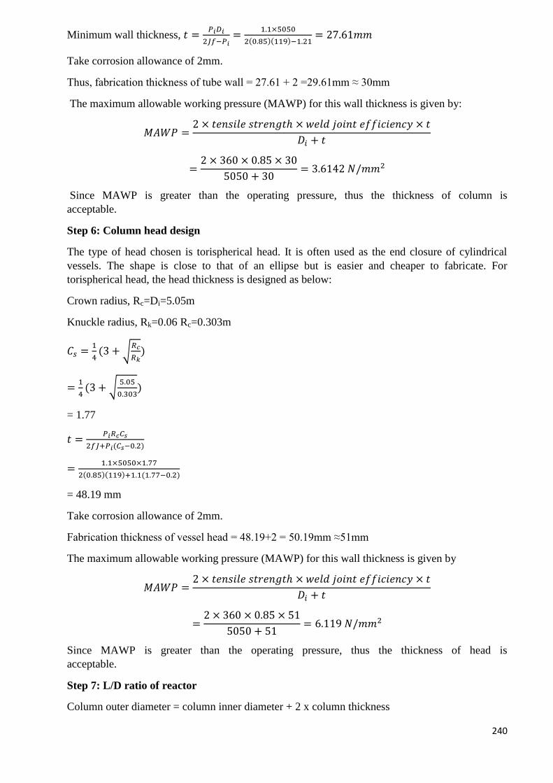
240
Minimum wall thickness, 𝑡 =𝑃𝑖𝐷𝑖
2𝐽𝑓−𝑃𝑖=
1.1×5050
2(0.85)(119)−1.21= 27.61𝑚𝑚
Take corrosion allowance of 2mm.
Thus, fabrication thickness of tube wall = 27.61 + 2 =29.61mm ≈ 30mm
The maximum allowable working pressure (MAWP) for this wall thickness is given by:
𝑀𝐴𝑊𝑃 =2 × 𝑡𝑒𝑛𝑠𝑖𝑙𝑒 𝑠𝑡𝑟𝑒𝑛𝑔𝑡ℎ × 𝑤𝑒𝑙𝑑 𝑗𝑜𝑖𝑛𝑡 𝑒𝑓𝑓𝑖𝑐𝑖𝑒𝑛𝑐𝑦 × 𝑡
𝐷𝑖 + 𝑡
=2 × 360 × 0.85 × 30
5050 + 30= 3.6142 𝑁/𝑚𝑚2
Since MAWP is greater than the operating pressure, thus the thickness of column is
acceptable.
Step 6: Column head design
The type of head chosen is torispherical head. It is often used as the end closure of cylindrical
vessels. The shape is close to that of an ellipse but is easier and cheaper to fabricate. For
torispherical head, the head thickness is designed as below:
Crown radius, Rc=Di=5.05m
Knuckle radius, Rk=0.06 Rc=0.303m
𝐶𝑠 =1
4(3 + √
𝑅𝑐
𝑅𝑘)
=1
4(3 + √
5.05
0.303)
= 1.77
𝑡 =𝑃𝑖𝑅𝑐𝐶𝑠
2𝑓𝐽+𝑃𝑖(𝐶𝑠−0.2)
=1.1×5050×1.77
2(0.85)(119)+1.1(1.77−0.2)
= 48.19 mm
Take corrosion allowance of 2mm.
Fabrication thickness of vessel head = 48.19+2 = 50.19mm ≈51mm
The maximum allowable working pressure (MAWP) for this wall thickness is given by
𝑀𝐴𝑊𝑃 =2 × 𝑡𝑒𝑛𝑠𝑖𝑙𝑒 𝑠𝑡𝑟𝑒𝑛𝑔𝑡ℎ × 𝑤𝑒𝑙𝑑 𝑗𝑜𝑖𝑛𝑡 𝑒𝑓𝑓𝑖𝑐𝑖𝑒𝑛𝑐𝑦 × 𝑡
𝐷𝑖 + 𝑡
=2 × 360 × 0.85 × 51
5050 + 51= 6.119 𝑁/𝑚𝑚2
Since MAWP is greater than the operating pressure, thus the thickness of head is
acceptable.
Step 7: L/D ratio of reactor
Column outer diameter = column inner diameter + 2 x column thickness
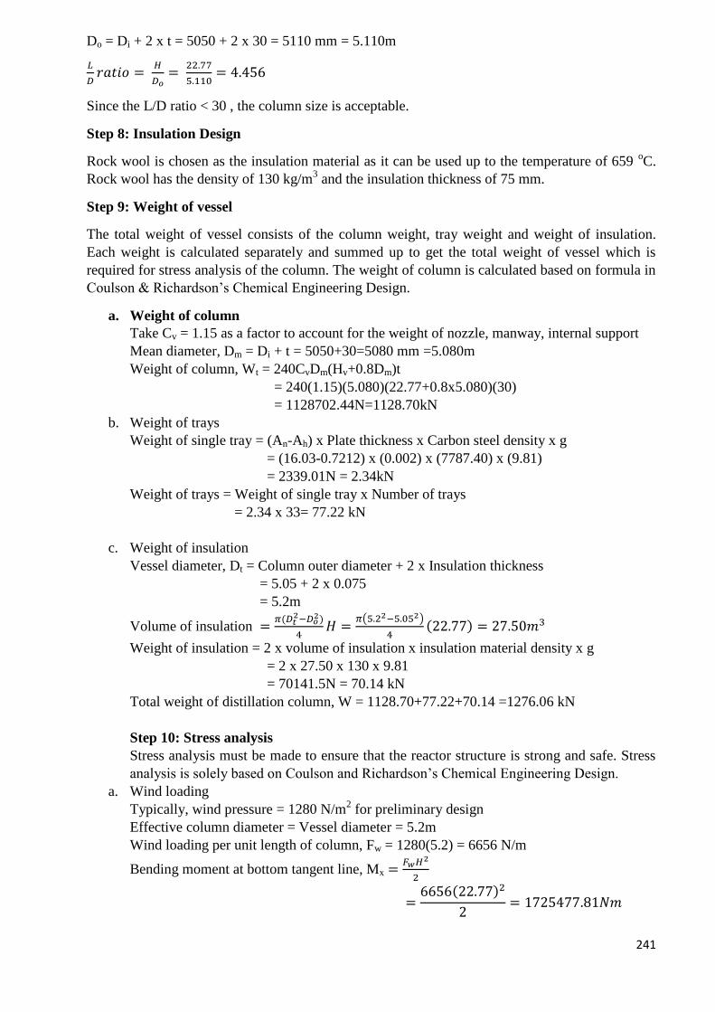
241
Do = Di + 2 x t = 5050 + 2 x 30 = 5110 mm = 5.110m
𝐿
𝐷𝑟𝑎𝑡𝑖𝑜 =
𝐻
𝐷𝑜=
22.77
5.110= 4.456
Since the L/D ratio < 30 , the column size is acceptable.
Step 8: Insulation Design
Rock wool is chosen as the insulation material as it can be used up to the temperature of 659 oC.
Rock wool has the density of 130 kg/m3 and the insulation thickness of 75 mm.
Step 9: Weight of vessel
The total weight of vessel consists of the column weight, tray weight and weight of insulation.
Each weight is calculated separately and summed up to get the total weight of vessel which is
required for stress analysis of the column. The weight of column is calculated based on formula in
Coulson & Richardson’s Chemical Engineering Design.
a. Weight of column
Take Cv = 1.15 as a factor to account for the weight of nozzle, manway, internal support
Mean diameter, Dm = Di + t = 5050+30=5080 mm =5.080m
Weight of column, Wt = 240CvDm(Hv+0.8Dm)t
= 240(1.15)(5.080)(22.77+0.8x5.080)(30)
= 1128702.44N=1128.70kN
b. Weight of trays
Weight of single tray = (An-Ah) x Plate thickness x Carbon steel density x g
= (16.03-0.7212) x (0.002) x (7787.40) x (9.81)
= 2339.01N = 2.34kN
Weight of trays = Weight of single tray x Number of trays
= 2.34 x 33= 77.22 kN
c. Weight of insulation
Vessel diameter, Dt = Column outer diameter + 2 x Insulation thickness
= 5.05 + 2 x 0.075
= 5.2m
Volume of insulation =𝜋(𝐷𝑡
2−𝐷𝑜2)
4𝐻 =
𝜋(5.22−5.052)
4(22.77) = 27.50𝑚3
Weight of insulation = 2 x volume of insulation x insulation material density x g
= 2 x 27.50 x 130 x 9.81
= 70141.5N = 70.14 kN
Total weight of distillation column, W = 1128.70+77.22+70.14 =1276.06 kN
Step 10: Stress analysis
Stress analysis must be made to ensure that the reactor structure is strong and safe. Stress
analysis is solely based on Coulson and Richardson’s Chemical Engineering Design.
a. Wind loading
Typically, wind pressure = 1280 N/m2 for preliminary design
Effective column diameter = Vessel diameter = 5.2m
Wind loading per unit length of column, Fw = 1280(5.2) = 6656 N/m
Bending moment at bottom tangent line, Mx =𝐹𝑤𝐻2
2
=6656(22.77)2
2= 1725477.81𝑁𝑚
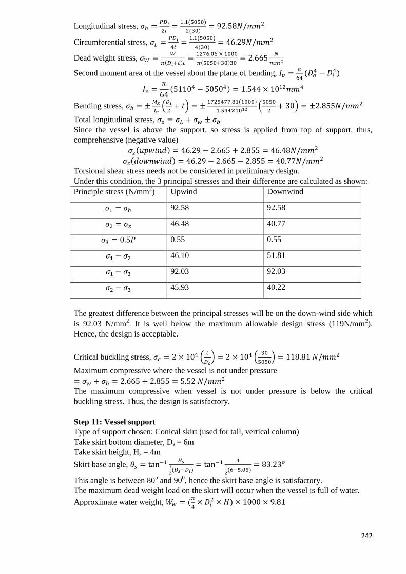
242
Longitudinal stress, 𝜎ℎ =𝑃𝐷𝑖
2𝑡=
1.1(5050)
2(30)= 92.58𝑁/𝑚𝑚2
Circumferential stress, 𝜎𝐿 =𝑃𝐷𝑖
4𝑡=
1.1(5050)
4(30)= 46.29𝑁/𝑚𝑚2
Dead weight stress, 𝜎𝑊 =𝑊
𝜋(𝐷𝑖+𝑡)𝑡=
1276.06 × 1000
𝜋(5050+30)30= 2.665
𝑁
𝑚𝑚2
Second moment area of the vessel about the plane of bending, 𝐼𝑣 =𝜋
64(𝐷𝑜
4 − 𝐷𝑖4)
𝐼𝑣 =𝜋
64(51104 − 50504) = 1.544 × 10¹²𝑚𝑚4
Bending stress, 𝜎𝑏 = ±𝑀𝑥
𝐼𝑣(𝐷𝑖
2+ 𝑡) = ±
1725477.81(1000)
1.544×10¹² (5050
2+ 30) = ±2.855𝑁/𝑚𝑚2
Total longitudinal stress, 𝜎𝑧 = 𝜎𝐿 + 𝜎𝑤 ± 𝜎𝑏
Since the vessel is above the support, so stress is applied from top of support, thus,
comprehensive (negative value)
𝜎𝑧(𝑢𝑝𝑤𝑖𝑛𝑑) = 46.29 − 2.665 + 2.855 = 46.48𝑁/𝑚𝑚2
𝜎𝑧(𝑑𝑜𝑤𝑛𝑤𝑖𝑛𝑑) = 46.29 − 2.665 − 2.855 = 40.77𝑁/𝑚𝑚2
Torsional shear stress needs not be considered in preliminary design.
Under this condition, the 3 principal stresses and their difference are calculated as shown:
Principle stress (N/mm2) Upwind Downwind
𝜎1 = 𝜎ℎ 92.58 92.58
𝜎2 = 𝜎𝑧 46.48 40.77
𝜎3 = 0.5𝑃 0.55 0.55
𝜎1 − 𝜎2 46.10 51.81
𝜎1 − 𝜎3 92.03 92.03
𝜎2 − 𝜎3 45.93 40.22
The greatest difference between the principal stresses will be on the down-wind side which
is 92.03 N/mm2. It is well below the maximum allowable design stress (119N/mm
2).
Hence, the design is acceptable.
Critical buckling stress, 𝜎𝑐 = 2 × 10⁴ (𝑡
𝐷𝑜) = 2 × 10⁴ (
30
5050) = 118.81 𝑁/𝑚𝑚2
Maximum compressive where the vessel is not under pressure
= 𝜎𝑤 + 𝜎𝑏 = 2.665 + 2.855 = 5.52 𝑁/𝑚𝑚2
The maximum compressive when vessel is not under pressure is below the critical
buckling stress. Thus, the design is satisfactory.
Step 11: Vessel support
Type of support chosen: Conical skirt (used for tall, vertical column)
Take skirt bottom diameter, Ds = 6m
Take skirt height, Hs = 4m
Skirt base angle, 𝜃𝑠 = tan−1 𝐻𝑠1
2(𝐷𝑠−𝐷𝑖)
= tan−1 41
2(6−5.05)
= 83.23𝑜
This angle is between 80o and 90
0, hence the skirt base angle is satisfactory.
The maximum dead weight load on the skirt will occur when the vessel is full of water.
Approximate water weight, 𝑊𝑤 = (𝜋
4× 𝐷𝑖
2 × 𝐻) × 1000 × 9.81

243
= (𝜋
4× 5.052 × 22.77) × 1000 × 9.81
= 4474089.58𝑁 = 4474.09𝑘𝑁
Take skirt thickness, ts be 9mm,
Bending moment at bottom of skirt, 𝑀𝑠 =𝐹𝑤(𝐻+𝐻𝑠)
2
2
=6656(22.77 + 4)2
2
= 2384954.29 𝑁𝑚
Bending stress in skirt, 𝜎𝑏𝑠 =4𝑀𝑠
𝜋(𝐷𝑠+𝑡𝑠)𝐷𝑠𝑡𝑠=
4(2384954.29)(103)
𝜋(6000+9)6000×9= 9.358 𝑁/𝑚𝑚2
Dead weight stress in the skirt, 𝜎𝑤𝑠(𝑡𝑒𝑠𝑡) =𝑊𝑤
𝜋(𝐷𝑠+𝑡𝑠)𝑡𝑠=
4474089.58
𝜋(6000+9)9= 26.33 𝑁/𝑚𝑚2
𝜎𝑤𝑠(𝑜𝑝𝑒𝑟𝑎𝑡𝑖𝑛𝑔) =𝑊
𝜋(𝐷𝑠 + 𝑡𝑠)𝑡𝑠=
1276.06 × 103
𝜋(6000 + 9)9= 7.51 𝑁/𝑚𝑚2
𝜎𝑠(𝑐𝑜𝑚𝑝𝑟𝑒𝑠𝑠𝑖𝑣𝑒) = 9.358 + 26.33 = 35.688 𝑁/𝑚𝑚2
𝜎𝑠(𝑡𝑒𝑛𝑠𝑖𝑙𝑒) = 9.358 − 7.51 = 1.848 𝑁/𝑚𝑚2
The skirt thickness should be such that under the worst combination of wind and dead-
weight loading, 2 design criteria must be satisfied. Choosing the skirt material to be carbon
steel, maximum allowable design stress at 20 oC is 135 N/mm
2. The young modulus of
stainless steel type 304 is 210000 MPa.
𝜎𝑠(𝑡𝑒𝑛𝑠𝑖𝑙𝑒) < 𝑓𝑠𝐽 sin 𝜃
1.848 < (0.85)(135) sin 83.23𝑜
1.848 < 113.95
𝜎𝑠(𝑐𝑜𝑚𝑝𝑟𝑒𝑠𝑠𝑖𝑣𝑒) < 0.125𝐸(𝑡𝑠
𝐷𝑠) sin 𝜃
35.688 < 0.125(210000)(9
6000) sin 83.23𝑜
35.688 < 39.10
Since both design criteria are satisfied, the skirt thickness is acceptable.
Take corrosion allowance of 2mm, skirt thickness =9+2=11mm
Step 12: Base ring and anchor bolt design
Take pitch circle diameter, Db =5.2m
Circumference of bolt circle = 5.2 X 10³(π)= 16336.28 mm
Minimum bolt spacing is recommended at 600mm
No of bolts required =16336.28
600= 27.23 ≈ 28 𝑏𝑜𝑙𝑡𝑠 (𝑚𝑢𝑠𝑡 𝑏𝑒 𝑚𝑢𝑙𝑡𝑖𝑝𝑙𝑒 𝑜𝑓 4)
Bolt stress, fb = 125 N/mm2 (from Coulson & Richardson’s Chemical Engineering Design)
Area of bolt, 𝐴𝑏 =1
𝑁𝑏𝑓𝑏[4𝑀𝑠
𝐷𝑏− 𝑊] =
1
28(125)[4(2384954.29)
5.2− 1276.06 × 103]
= 159.58 mm2
Diameter of bolt= √𝐴𝑏×4
𝜋= √
159.98×4
𝜋= 14.27𝑚𝑚
Referring to Figure 13.2 Coulson & Richardson 6th
volume 4th
edition, the bolt size of
M24 (root area 353) is used.
Total compressive load on base ring, Fb
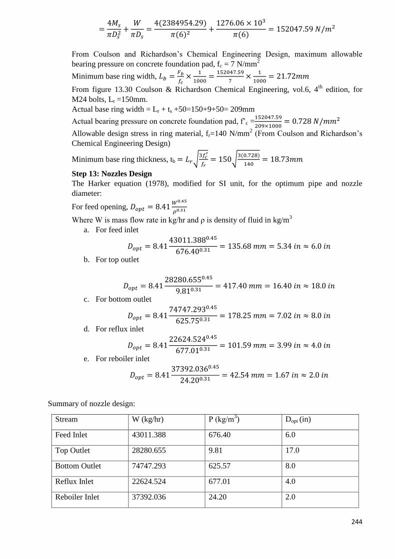
244
=4𝑀𝑠
𝜋𝐷𝑠2+
𝑊
𝜋𝐷𝑠=
4(2384954.29)
𝜋(6)2+
1276.06 × 103
𝜋(6)= 152047.59 𝑁/𝑚2
From Coulson and Richardson’s Chemical Engineering Design, maximum allowable
bearing pressure on concrete foundation pad, fc = 7 N/mm2
Minimum base ring width, 𝐿𝑏 =𝐹𝑏
𝑓𝑐×
1
1000=
152047.59
7×
1
1000= 21.72𝑚𝑚
From figure 13.30 Coulson & Richardson Chemical Engineering, vol.6, 4th
edition, for
M24 bolts, Lr =150mm.
Actual base ring width = Lr + ts +50=150+9+50= 209mm
Actual bearing pressure on concrete foundation pad, f’c =152047.59
209×1000= 0.728 𝑁/𝑚𝑚2
Allowable design stress in ring material, fr=140 N/mm2 (From Coulson and Richardson’s
Chemical Engineering Design)
Minimum base ring thickness, tb = 𝐿𝑟√3𝑓𝑐
′
𝑓𝑟= 150√
3(0.728)
140= 18.73𝑚𝑚
Step 13: Nozzles Design
The Harker equation (1978), modified for SI unit, for the optimum pipe and nozzle
diameter:
For feed opening, 𝐷𝑜𝑝𝑡 = 8.41𝑊0.45
𝜌0.31
Where W is mass flow rate in kg/hr and ρ is density of fluid in kg/m3
a. For feed inlet
𝐷𝑜𝑝𝑡 = 8.4143011.3880.45
676.400.31= 135.68 𝑚𝑚 = 5.34 𝑖𝑛 ≈ 6.0 𝑖𝑛
b. For top outlet
𝐷𝑜𝑝𝑡 = 8.4128280.6550.45
9.810.31= 417.40 𝑚𝑚 = 16.40 𝑖𝑛 ≈ 18.0 𝑖𝑛
c. For bottom outlet
𝐷𝑜𝑝𝑡 = 8.4174747.2930.45
625.750.31= 178.25 𝑚𝑚 = 7.02 𝑖𝑛 ≈ 8.0 𝑖𝑛
d. For reflux inlet
𝐷𝑜𝑝𝑡 = 8.4122624.5240.45
677.010.31= 101.59 𝑚𝑚 = 3.99 𝑖𝑛 ≈ 4.0 𝑖𝑛
e. For reboiler inlet
𝐷𝑜𝑝𝑡 = 8.4137392.0360.45
24.200.31= 42.54 𝑚𝑚 = 1.67 𝑖𝑛 ≈ 2.0 𝑖𝑛
Summary of nozzle design:
Stream W (kg/hr) Ρ (kg/m3) Dopt (in)
Feed Inlet 43011.388 676.40 6.0
Top Outlet 28280.655 9.81 17.0
Bottom Outlet 74747.293 625.57 8.0
Reflux Inlet 22624.524 677.01 4.0
Reboiler Inlet 37392.036 24.20 2.0
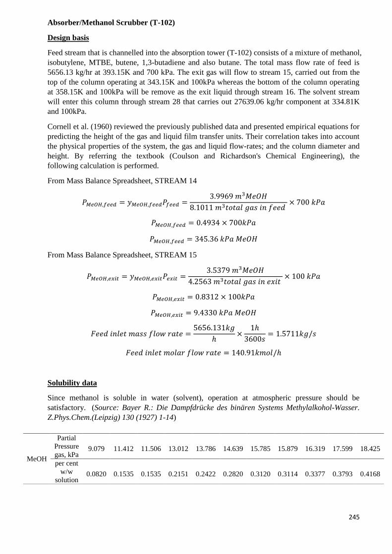
245
Absorber/Methanol Scrubber (T-102)
Design basis
Feed stream that is channelled into the absorption tower (T-102) consists of a mixture of methanol,
isobutylene, MTBE, butene, 1,3-butadiene and also butane. The total mass flow rate of feed is
5656.13 kg/hr at 393.15K and 700 kPa. The exit gas will flow to stream 15, carried out from the
top of the column operating at 343.15K and 100kPa whereas the bottom of the column operating
at 358.15K and 100kPa will be remove as the exit liquid through stream 16. The solvent stream
will enter this column through stream 28 that carries out 27639.06 kg/hr component at 334.81K
and 100kPa.
Cornell et al. (1960) reviewed the previously published data and presented empirical equations for
predicting the height of the gas and liquid film transfer units. Their correlation takes into account
the physical properties of the system, the gas and liquid flow-rates; and the column diameter and
height. By referring the textbook (Coulson and Richardson's Chemical Engineering), the
following calculation is performed.
From Mass Balance Spreadsheet, STREAM 14
𝑃𝑀𝑒𝑂𝐻,𝑓𝑒𝑒𝑑 = 𝑦𝑀𝑒𝑂𝐻,𝑓𝑒𝑒𝑑𝑃𝑓𝑒𝑒𝑑 =3.9969 𝑚3𝑀𝑒𝑂𝐻
8.1011 𝑚3𝑡𝑜𝑡𝑎𝑙 𝑔𝑎𝑠 𝑖𝑛 𝑓𝑒𝑒𝑑 × 700 𝑘𝑃𝑎
𝑃𝑀𝑒𝑂𝐻,𝑓𝑒𝑒𝑑 = 0.4934 × 700𝑘𝑃𝑎
𝑃𝑀𝑒𝑂𝐻,𝑓𝑒𝑒𝑑 = 345.36 𝑘𝑃𝑎 𝑀𝑒𝑂𝐻
From Mass Balance Spreadsheet, STREAM 15
𝑃𝑀𝑒𝑂𝐻,𝑒𝑥𝑖𝑡 = 𝑦𝑀𝑒𝑂𝐻,𝑒𝑥𝑖𝑡𝑃𝑒𝑥𝑖𝑡 =3.5379 𝑚3𝑀𝑒𝑂𝐻
4.2563 𝑚3𝑡𝑜𝑡𝑎𝑙 𝑔𝑎𝑠 𝑖𝑛 𝑒𝑥𝑖𝑡 × 100 𝑘𝑃𝑎
𝑃𝑀𝑒𝑂𝐻,𝑒𝑥𝑖𝑡 = 0.8312 × 100𝑘𝑃𝑎
𝑃𝑀𝑒𝑂𝐻,𝑒𝑥𝑖𝑡 = 9.4330 𝑘𝑃𝑎 𝑀𝑒𝑂𝐻
𝐹𝑒𝑒𝑑 𝑖𝑛𝑙𝑒𝑡 𝑚𝑎𝑠𝑠 𝑓𝑙𝑜𝑤 𝑟𝑎𝑡𝑒 =5656.131𝑘𝑔
ℎ×
1ℎ
3600𝑠= 1.5711𝑘𝑔/𝑠
𝐹𝑒𝑒𝑑 𝑖𝑛𝑙𝑒𝑡 𝑚𝑜𝑙𝑎𝑟 𝑓𝑙𝑜𝑤 𝑟𝑎𝑡𝑒 = 140.91𝑘𝑚𝑜𝑙/ℎ
Solubility data
Since methanol is soluble in water (solvent), operation at atmospheric pressure should be
satisfactory. (Source: Bayer R.: Die Dampfdrücke des binären Systems Methylalkohol-Wasser.
Z.Phys.Chem.(Leipzig) 130 (1927) 1-14)
MeOH
Partial
Pressure
gas, kPa 9.079 11.412 11.506 13.012 13.786 14.639 15.785 15.879 16.319 17.599 18.425
per cent
w/w
solution 0.0820 0.1535 0.1535 0.2151 0.2422 0.2820 0.3120 0.3114 0.3377 0.3793 0.4168
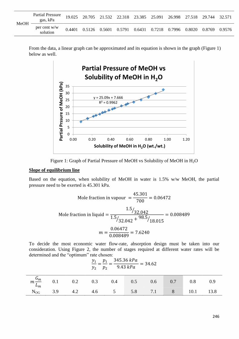
246
MeOH
Partial Pressure
gas, kPa 19.025 20.705 21.532 22.318 23.385 25.091 26.998 27.518 29.744 32.571
per cent w/w
solution 0.4401 0.5126 0.5601 0.5791 0.6431 0.7218 0.7996 0.8020 0.8769 0.9576
From the data, a linear graph can be approximated and its equation is shown in the graph (Figure 1)
below as well.
Figure 1: Graph of Partial Pressure of MeOH vs Solubility of MeOH in H2O
Slope of equilibrium line
Based on the equation, when solubility of MeOH in water is 1.5% w/w MeOH, the partial
pressure need to be exerted is 45.301 kPa.
Mole fraction in vapour =45.301
700= 0.06472
Mole fraction in liquid =1.5
32.042⁄
1.532.042⁄ + 98.5
18.015⁄= 0.008489
𝑚 =0.06472
0.008489= 7.6240
To decide the most economic water flow-rate, absorption design must be taken into our
consideration. Using Figure 2, the number of stages required at different water rates will be
determined and the “optimum” rate chosen: 𝑦1
𝑦2=
𝑝1
𝑝2=
345.36 𝑘𝑃𝑎
9.43 𝑘𝑃𝑎= 34.62
𝑚𝐺𝑚
𝐿𝑚 0.1 0.2 0.3 0.4 0.5 0.6 0.7 0.8 0.9
NOG 3.9 4.2 4.6 5 5.8 7.1 8 10.1 13.8
y = 25.09x + 7.666 R² = 0.9962
0
5
10
15
20
25
30
35
0.00 0.20 0.40 0.60 0.80 1.00 1.20Par
tial
Prs
sure
of
MeO
H (
kPa)
Solubility of MeOH in H2O (wt./wt.)
Partial Pressure of MeOH vs Solubility of MeOH in H2O
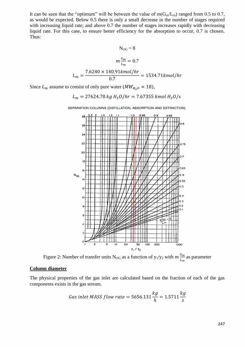
247
It can be seen that the “optimum” will be between the value of m(Gm/Lm) ranged from 0.5 to 0.7,
as would be expected. Below 0.5 there is only a small decrease in the number of stages required
with increasing liquid rate; and above 0.7 the number of stages increases rapidly with decreasing
liquid rate. For this case, to ensure better efficiency for the absorption to occur, 0.7 is chosen.
Thus:
NOG = 8
𝑚𝐺𝑚
𝐿𝑚= 0.7
𝐿𝑚 =7.6240 × 140.91𝑘𝑚𝑜𝑙/ℎ𝑟
0.7= 1534.71𝑘𝑚𝑜𝑙/ℎ𝑟
Since 𝐿𝑚 assume to consist of only pure water (𝑀𝑊𝐻2𝑂 ≈ 18),
𝐿𝑚 = 27624.78 𝑘𝑔 𝐻2𝑂/ℎ𝑟 = 7.67355 𝑘𝑚𝑜𝑙 𝐻2𝑂/𝑠
Figure 2: Number of transfer units NOG as a function of y1/y2 with 𝑚𝐺𝑚
𝐿𝑚 as parameter
Column diameter
The physical properties of the gas inlet are calculated based on the fraction of each of the gas
components exists in the gas stream.
𝐺𝑎𝑠 𝑖𝑛𝑙𝑒𝑡 𝑀𝐴𝑆𝑆 𝑓𝑙𝑜𝑤 𝑟𝑎𝑡𝑒 = 5656.131𝑘𝑔
ℎ= 1.5711
𝑘𝑔
𝑠
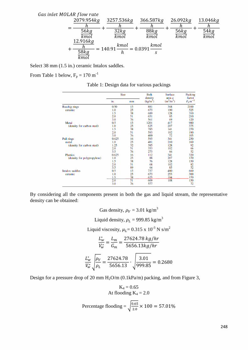
248
𝐺𝑎𝑠 𝑖𝑛𝑙𝑒𝑡 𝑀𝑂𝐿𝐴𝑅 𝑓𝑙𝑜𝑤 𝑟𝑎𝑡𝑒
=
2079.954𝑘𝑔ℎ
56𝑘𝑔𝑘𝑚𝑜𝑙
+
3257.536𝑘𝑔ℎ
32𝑘𝑔𝑘𝑚𝑜𝑙
+
366.587𝑘𝑔ℎ
88𝑘𝑔𝑘𝑚𝑜𝑙
+
26.092𝑘𝑔ℎ
56𝑘𝑔𝑘𝑚𝑜𝑙
+
13.046𝑘𝑔ℎ
54𝑘𝑔𝑘𝑚𝑜𝑙
+
12.916𝑘𝑔ℎ
58𝑘𝑔𝑘𝑚𝑜𝑙
= 140.91𝑘𝑚𝑜𝑙
ℎ= 0.0391
𝑘𝑚𝑜𝑙
𝑠
Select 38 mm (1.5 in.) ceramic Intalox saddles.
From Table 1 below, Fp = 170 m-1
Table 1: Design data for various packings
By considering all the components present in both the gas and liquid stream, the representative
density can be obtained:
Gas density, 𝜌𝑉 = 3.01 kg/m3
Liquid density, 𝜌𝐿 = 999.85 kg/m3
Liquid viscosity, 𝜇𝐿= 0.315 x 10⁻³
N s/m2
𝐿𝑤∗
𝑉𝑤∗
=𝐿𝑚
𝐺𝑚=
27624.78 𝑘𝑔/ℎ𝑟
5656.13𝑘𝑔/ℎ𝑟
𝐿𝑤∗
𝑉𝑤∗ √
𝜌𝑉
𝜌𝐿=
27624.78
5656.13∙ √
3.01
999.85= 0.2680
Design for a pressure drop of 20 mm H2O/m (0.1kPa/m) packing, and from Figure 3,
K4 = 0.65
At flooding K4 = 2.0
Percentage flooding = √0.65
2.0× 100 = 57.01%
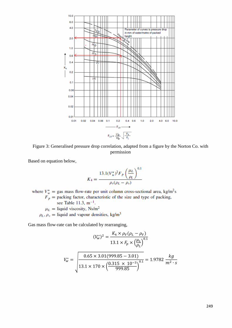
249
Figure 3: Generalised pressure drop correlation, adapted from a figure by the Norton Co. with
permission
Based on equation below,
Gas mass flow-rate can be calculated by rearranging,
(𝑉𝑤∗)2 =
𝐾4 × 𝜌𝑉(𝜌𝐿 − 𝜌𝑉)
13.1 × 𝐹𝑝 × (𝜇𝐿
𝜌𝐿)0.1
𝑉𝑤∗ =
√
0.65 × 3.01(999.85 − 3.01)
13.1 × 170 × (0.315 × 10−3
999.85)0.1 = 1.9782
𝑘𝑔
𝑚2 ∙ 𝑠
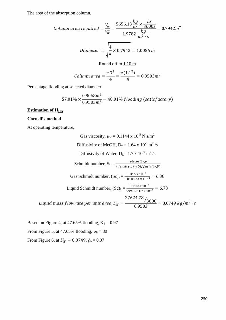
250
The area of the absorption column,
𝐶𝑜𝑙𝑢𝑚𝑛 𝑎𝑟𝑒𝑎 𝑟𝑒𝑞𝑢𝑖𝑟𝑒𝑑 =𝑉𝑤
𝑉𝑤∗=
5656.13𝑘𝑔ℎ𝑟
×ℎ𝑟
3600𝑠
1.9782 𝑘𝑔
𝑚2 ∙ 𝑠
= 0.7942𝑚2
𝐷𝑖𝑎𝑚𝑒𝑡𝑒𝑟 = √4
𝜋× 0.7942 = 1.0056 𝑚
Round off to 1.10 m
𝐶𝑜𝑙𝑢𝑚𝑛 𝑎𝑟𝑒𝑎 =𝜋𝐷2
4=
𝜋(1.12)
4= 0.9503𝑚2
Percentage flooding at selected diameter,
57.01% ×0.8068𝑚2
0.9503𝑚2= 48.01% 𝑓𝑙𝑜𝑜𝑑𝑖𝑛𝑔 (𝑠𝑎𝑡𝑖𝑠𝑓𝑎𝑐𝑡𝑜𝑟𝑦)
Estimation of HOG
Cornell’s method
At operating temperature,
Gas viscosity, 𝜇𝑉 = 0.1144 x 10⁻⁵
N s/m2
Diffusivity of MeOH, Dv = 1.64 x 10⁻⁵
m2 /s
Diffusivity of Water, DL= 1.7 x 10⁻⁹
m2 /s
Schmidt number, Sc = 𝑣𝑖𝑠𝑐𝑜𝑠𝑖𝑡𝑦,𝑣
(𝑑𝑒𝑛𝑠𝑖𝑡𝑦,𝜌)×(𝐷𝑖𝑓𝑓𝑢𝑠𝑖𝑣𝑖𝑡𝑦,𝐷)
Gas Schmidt number, (Sc)v = 0.315 x 10⁻³
3.01×1.64 x 10−5= 6.38
Liquid Schmidt number, (Sc)L = 0.1144x 10⁻⁴
999.85×1.7 x 10−9 = 6.73
𝐿𝑖𝑞𝑢𝑖𝑑 𝑚𝑎𝑠𝑠 𝑓𝑙𝑜𝑤𝑟𝑎𝑡𝑒 𝑝𝑒𝑟 𝑢𝑛𝑖𝑡 𝑎𝑟𝑒𝑎, 𝐿𝑊∗ =
27624.78 3600⁄
0.9503= 8.0749 𝑘𝑔/𝑚2 ∙ 𝑠
Based on Figure 4, at 47.65% flooding, K3 = 0.97
From Figure 5, at 47.65% flooding, ψh = 80
From Figure 6, at 𝐿𝑊∗ = 8.0749, ϕh = 0.07
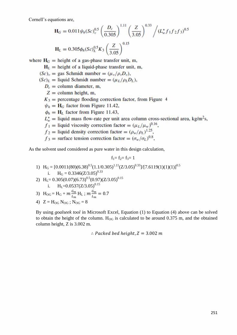
251
Cornell’s equations are,
As the solvent used considered as pure water in this design calculation,
f1= f2= f3= 1
1) HG = [0.0011(80)(6.38)0.5
(1.1/0.305)1.11
(Z/3.05)0.33
]/[7.6119(1)(1)(1)]0.5
i. HG = 0.3346(Z/3.05)0.33
2) HL= 0.305(0.07)(6.73)0.5
(0.97)(Z/3.05)0.15
i. HL=0.0537(Z/3.05)0.15
3) HOG = HG + 𝑚𝐺𝑚
𝐿𝑚 HL ; 𝑚
𝐺𝑚
𝐿𝑚= 0.7
4) Z = HOG NOG ; NOG = 8
By using goalseek tool in Microsoft Excel, Equation (1) to Equation (4) above can be solved
to obtain the height of the column. HOG is calculated to be around 0.375 m, and the obtained
column height, Z is 3.002 m.
∴ 𝑃𝑎𝑐𝑘𝑒𝑑 𝑏𝑒𝑑 ℎ𝑒𝑖𝑔ℎ𝑡, 𝑍 = 3.002 𝑚
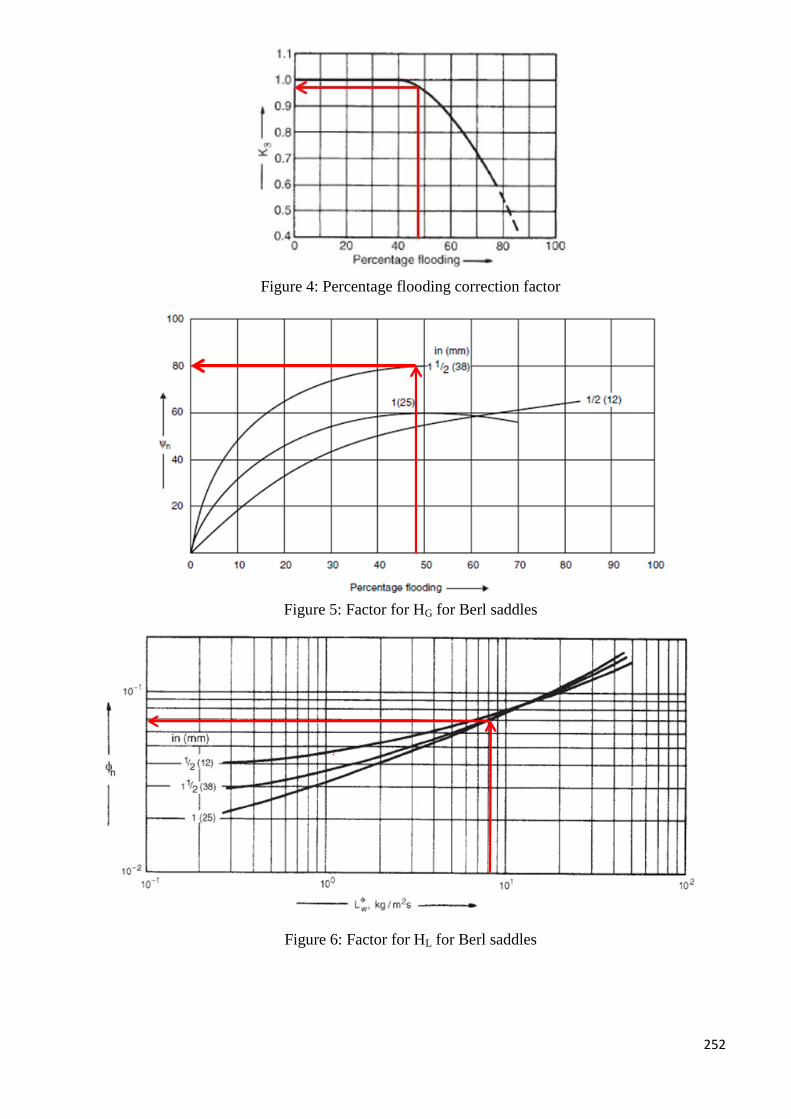
252
Figure 4: Percentage flooding correction factor
Figure 5: Factor for HG for Berl saddles
Figure 6: Factor for HL for Berl saddles
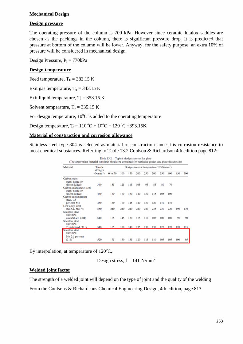
253
Mechanical Design
Design pressure
The operating pressure of the column is 700 kPa. However since ceramic Intalox saddles are
chosen as the packings in the column, there is significant pressure drop. It is predicted that
pressure at bottom of the column will be lower. Anyway, for the safety purpose, an extra 10% of
pressure will be considered in mechanical design.
Design Pressure, Pi = 770kPa
Design temperature
Feed temperature, TF = 383.15 K
Exit gas temperature, Tg = 343.15 K
Exit liquid temperature, Tl = 358.15 K
Solvent temperature, Ts = 335.15 K
For design temperature, 10oC is added to the operating temperature
Design temperature, Ti = 110 oC + 10
oC = 120
oC =393.15K
Material of construction and corrosion allowance
Stainless steel type 304 is selected as material of construction since it is corrosion resistance to
most chemical substances. Referring to Table 13.2 Coulson & Richardson 4th edition page 812:
By interpolation, at temperature of 120oC,
Design stress, f = 141 N/mm2
Welded joint factor
The strength of a welded joint will depend on the type of joint and the quality of the welding
From the Coulsons & Richardsons Chemical Engineering Design, 4th edition, page 813
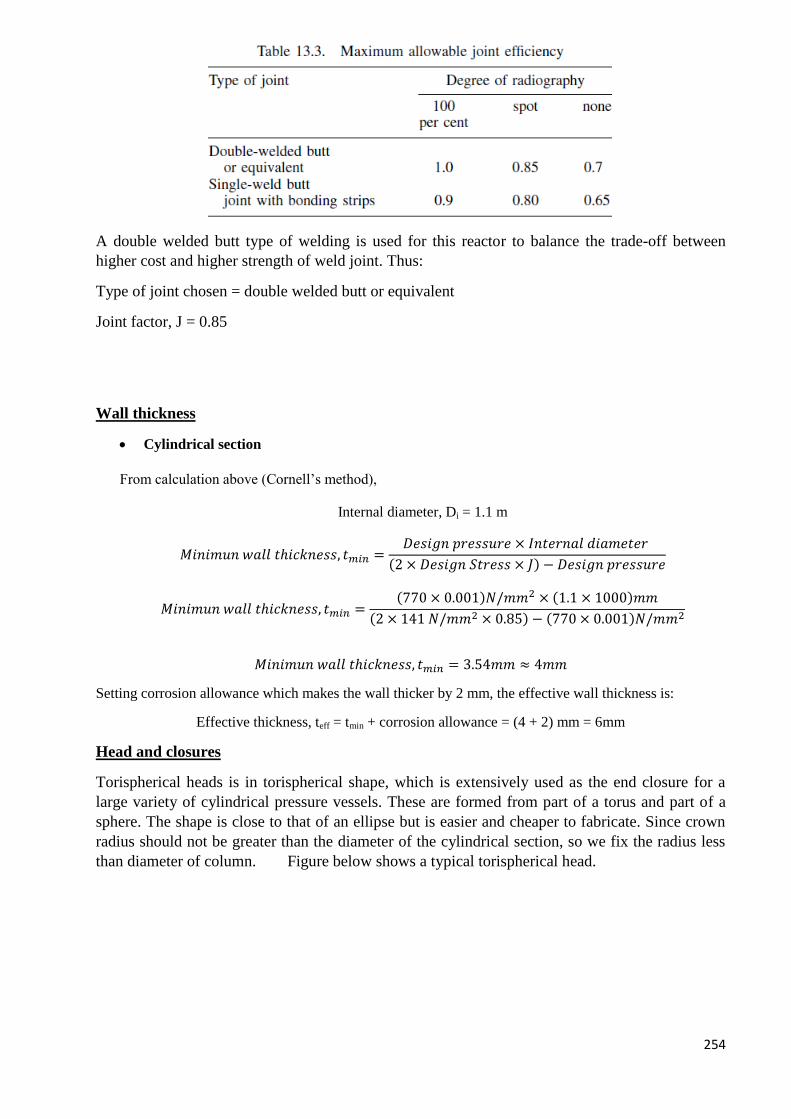
254
A double welded butt type of welding is used for this reactor to balance the trade-off between
higher cost and higher strength of weld joint. Thus:
Type of joint chosen = double welded butt or equivalent
Joint factor, J = 0.85
Wall thickness
Cylindrical section
From calculation above (Cornell’s method),
Internal diameter, Di = 1.1 m
𝑀𝑖𝑛𝑖𝑚𝑢𝑛 𝑤𝑎𝑙𝑙 𝑡ℎ𝑖𝑐𝑘𝑛𝑒𝑠𝑠, 𝑡𝑚𝑖𝑛 =𝐷𝑒𝑠𝑖𝑔𝑛 𝑝𝑟𝑒𝑠𝑠𝑢𝑟𝑒 × 𝐼𝑛𝑡𝑒𝑟𝑛𝑎𝑙 𝑑𝑖𝑎𝑚𝑒𝑡𝑒𝑟
(2 × 𝐷𝑒𝑠𝑖𝑔𝑛 𝑆𝑡𝑟𝑒𝑠𝑠 × 𝐽) − 𝐷𝑒𝑠𝑖𝑔𝑛 𝑝𝑟𝑒𝑠𝑠𝑢𝑟𝑒
𝑀𝑖𝑛𝑖𝑚𝑢𝑛 𝑤𝑎𝑙𝑙 𝑡ℎ𝑖𝑐𝑘𝑛𝑒𝑠𝑠, 𝑡𝑚𝑖𝑛 =(770 × 0.001)𝑁/𝑚𝑚2 × (1.1 × 1000)𝑚𝑚
(2 × 141 𝑁/𝑚𝑚2 × 0.85) − (770 × 0.001)𝑁/𝑚𝑚2
𝑀𝑖𝑛𝑖𝑚𝑢𝑛 𝑤𝑎𝑙𝑙 𝑡ℎ𝑖𝑐𝑘𝑛𝑒𝑠𝑠, 𝑡𝑚𝑖𝑛 = 3.54𝑚𝑚 ≈ 4𝑚𝑚
Setting corrosion allowance which makes the wall thicker by 2 mm, the effective wall thickness is:
Effective thickness, teff = tmin + corrosion allowance = (4 + 2) mm = 6mm
Head and closures
Torispherical heads is in torispherical shape, which is extensively used as the end closure for a
large variety of cylindrical pressure vessels. These are formed from part of a torus and part of a
sphere. The shape is close to that of an ellipse but is easier and cheaper to fabricate. Since crown
radius should not be greater than the diameter of the cylindrical section, so we fix the radius less
than diameter of column. Figure below shows a typical torispherical head.
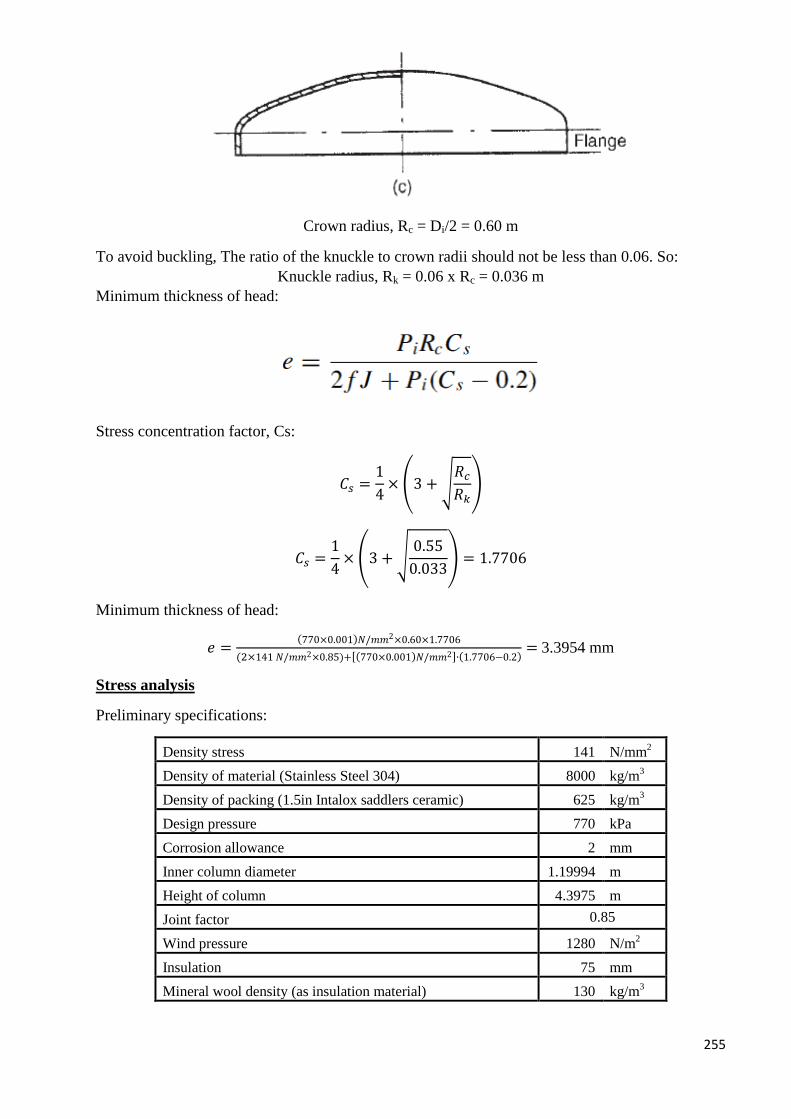
255
Crown radius, Rc = Di/2 = 0.60 m
To avoid buckling, The ratio of the knuckle to crown radii should not be less than 0.06. So:
Knuckle radius, Rk = 0.06 x Rc = 0.036 m
Minimum thickness of head:
Stress concentration factor, Cs:
𝐶𝑠 =1
4× (3 + √
𝑅𝑐
𝑅𝑘)
𝐶𝑠 =1
4× (3 + √
0.55
0.033) = 1.7706
Minimum thickness of head:
𝑒 =(770×0.001)𝑁/𝑚𝑚2×0.60×1.7706
(2×141 𝑁/𝑚𝑚2×0.85)+[(770×0.001)𝑁/𝑚𝑚2]∙(1.7706−0.2)= 3.3954 mm
Stress analysis
Preliminary specifications:
Density stress 141 N/mm2
Density of material (Stainless Steel 304) 8000 kg/m3
Density of packing (1.5in Intalox saddlers ceramic) 625 kg/m3
Design pressure 770 kPa
Corrosion allowance 2 mm
Inner column diameter 1.19994 m
Height of column 4.3975 m
Joint factor 0.85
Wind pressure 1280 N/m2
Insulation 75 mm
Mineral wool density (as insulation material) 130 kg/m3
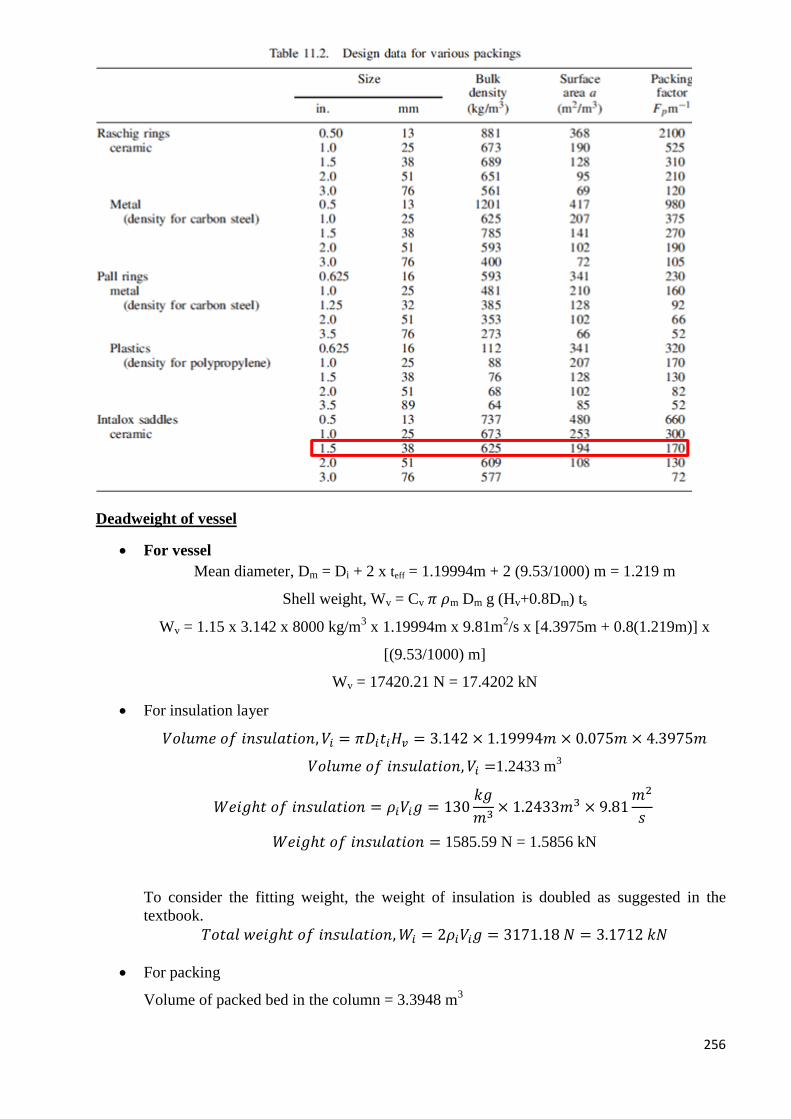
256
Deadweight of vessel
For vessel
Mean diameter, Dm = Di + 2 x teff = 1.19994m + 2 (9.53/1000) m = 1.219 m
Shell weight, Wv = Cv 𝜋 𝜌m Dm g (Hv+0.8Dm) ts
Wv = 1.15 x 3.142 x 8000 kg/m3 x 1.19994m x 9.81m
2/s x [4.3975m + 0.8(1.219m)] x
[(9.53/1000) m]
Wv = 17420.21 N = 17.4202 kN
For insulation layer
𝑉𝑜𝑙𝑢𝑚𝑒 𝑜𝑓 𝑖𝑛𝑠𝑢𝑙𝑎𝑡𝑖𝑜𝑛, 𝑉𝑖 = 𝜋𝐷𝑖𝑡𝑖𝐻𝑣 = 3.142 × 1.19994𝑚 × 0.075𝑚 × 4.3975𝑚
𝑉𝑜𝑙𝑢𝑚𝑒 𝑜𝑓 𝑖𝑛𝑠𝑢𝑙𝑎𝑡𝑖𝑜𝑛, 𝑉𝑖 =1.2433 m3
𝑊𝑒𝑖𝑔ℎ𝑡 𝑜𝑓 𝑖𝑛𝑠𝑢𝑙𝑎𝑡𝑖𝑜𝑛 = 𝜌𝑖𝑉𝑖𝑔 = 130𝑘𝑔
𝑚3× 1.2433𝑚3 × 9.81
𝑚2
𝑠
𝑊𝑒𝑖𝑔ℎ𝑡 𝑜𝑓 𝑖𝑛𝑠𝑢𝑙𝑎𝑡𝑖𝑜𝑛 = 1585.59 N = 1.5856 kN
To consider the fitting weight, the weight of insulation is doubled as suggested in the
textbook.
𝑇𝑜𝑡𝑎𝑙 𝑤𝑒𝑖𝑔ℎ𝑡 𝑜𝑓 𝑖𝑛𝑠𝑢𝑙𝑎𝑡𝑖𝑜𝑛,𝑊𝑖 = 2𝜌𝑖𝑉𝑖𝑔 = 3171.18 𝑁 = 3.1712 𝑘𝑁
For packing
Volume of packed bed in the column = 3.3948 m3
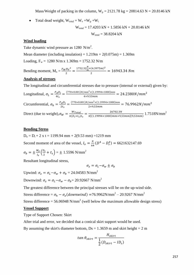
257
Mass/Weight of packing in the column, Wp = 2121.78 kg = 20814.63 N = 20.8146 kN
Total dead weight, Wtotal = Wv +Wp +Wi
Wtotal = 17.4203 kN + 1.5856 kN + 20.8146 kN
Wtotal = 38.8204 kN
Wind loading
Take dynamic wind pressure as 1280 N/m2.
Mean diameter (including insulation) = 1.219m + 2(0.075m) = 1.369m
Loading, Fw = 1280 N/m x 1.369m = 1752.32 N/m
Bending moment, Mx = 𝐹𝑊𝐻𝑉
2
2=
1752.32𝑁
𝑚×(4.3975𝑚)2
2= 16943.34 𝑁𝑚
Analysis of stresses
The longitudinal and circumferential stresses due to pressure (internal or external) given by:
Longitudinal, 𝜎𝐿 =𝑃𝑑𝐷𝑖
4𝑡𝑠=
(770×0.001)𝑁/𝑚𝑚2×(1.19994×1000)𝑚𝑚
4×9.53𝑚𝑚= 24.2380𝑁/𝑚𝑚2
Circumferential, 𝜎ℎ =𝑃𝑑𝐷𝑖
2𝑡𝑠=
(770×0.001)𝑁/𝑚𝑚2×(1.19994×1000)𝑚𝑚
2×9,53𝑚𝑚= 76.9962𝑁/𝑚𝑚2
Direct (due to weight),𝜎𝑊 =𝑊𝑇𝑜𝑡𝑎𝑙
𝜋(𝐷𝑖+𝑡𝑠)𝑡𝑠=
26702.3𝑁
𝜋[(1.19994×1000)𝑚𝑚+9,53𝑚𝑚](9,53𝑚𝑚) 1.7518N/mm
2
Bending Stress
Do = Di + 2 x t = 1199.94 mm + 2(9.53 mm) =1219 mm
Second moment of area of the vessel, 𝐼𝑣 =𝜋
64(𝐷4 − 𝐷𝑠
4) = 6621632147.69
𝜎𝑏 = ±𝑀𝑥
𝐼𝑣(𝐷𝑠
2+ 𝑡𝑠) = ± 1.5596 N/mm
2
Resultant longitudinal stress, 𝜎𝑧 = 𝜎𝐿−𝜎𝑤 ± 𝜎𝑏
Upwind: 𝜎𝑧 = 𝜎𝐿−𝜎𝑤 + 𝜎𝑏 = 24.04583 N/mm2
Downwind: 𝜎𝑧 = 𝜎𝐿−𝜎𝑤 − 𝜎𝑏= 20.92667 N/mm2
The greatest difference between the principal stresses will be on the up-wind side.
Stress difference = 𝜎ℎ − 𝜎𝑧(𝑑𝑜𝑤𝑛𝑤𝑖𝑛𝑑) =76.9962N/mm2 – 20.9267 N/mm
2
Stress difference = 56.06948 N/mm2 (well below the maximum allowable design stress)
Vessel Support
Type of Support Chosen: Skirt
After trial and error, we decided that a conical skirt support would be used.
By assuming the skirt's diameter bottom, Ds = 1.3659 m and skirt height = 2 m
𝑡𝑎𝑛 𝜃𝑠𝑘𝑖𝑟𝑡 =𝐻𝑠𝑘𝑖𝑟𝑡
12
(𝐷𝑠𝑘𝑖𝑟𝑡 − 𝐼𝐷𝑠)
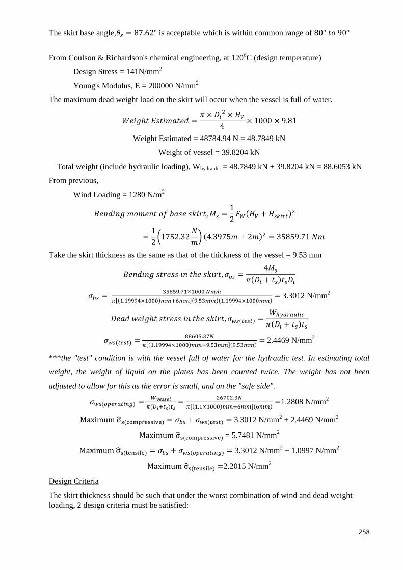
258
The skirt base angle,𝜃𝑠 = 87.62° is acceptable which is within common range of 80° 𝑡𝑜 90°
From Coulson & Richardson's chemical engineering, at 120oC (design temperature)
Design Stress = 141N/mm2
Young's Modulus, E = 200000 N/mm2
The maximum dead weight load on the skirt will occur when the vessel is full of water.
𝑊𝑒𝑖𝑔ℎ𝑡 𝐸𝑠𝑡𝑖𝑚𝑎𝑡𝑒𝑑 =𝜋 × 𝐷𝑖
2 × 𝐻𝑉
4× 1000 × 9.81
Weight Estimated = 48784.94 N = 48.7849 kN
Weight of vessel = 39.8204 kN
Total weight (include hydraulic loading), Whydraulic = 48.7849 kN + 39.8204 kN = 88.6053 kN
From previous,
Wind Loading = 1280 N/m2
𝐵𝑒𝑛𝑑𝑖𝑛𝑔 𝑚𝑜𝑚𝑒𝑛𝑡 𝑜𝑓 𝑏𝑎𝑠𝑒 𝑠𝑘𝑖𝑟𝑡,𝑀𝑠 =1
2𝐹𝑊(𝐻𝑉 + 𝐻𝑠𝑘𝑖𝑟𝑡)
2
=1
2(1752.32
𝑁
𝑚) (4.3975𝑚 + 2𝑚)2 = 35859.71 𝑁𝑚
Take the skirt thickness as the same as that of the thickness of the vessel = 9.53 mm
𝐵𝑒𝑛𝑑𝑖𝑛𝑔 𝑠𝑡𝑟𝑒𝑠𝑠 𝑖𝑛 𝑡ℎ𝑒 𝑠𝑘𝑖𝑟𝑡, 𝜎𝑏𝑠 =4𝑀𝑠
𝜋(𝐷𝑖 + 𝑡𝑠)𝑡𝑠𝐷𝑖
𝜎𝑏𝑠 = 35859.71×1000 𝑁𝑚𝑚
𝜋[(1.19994×1000)𝑚𝑚+6𝑚𝑚](9.53𝑚𝑚)(1.19994×1000𝑚𝑚)= 3.3012 N/mm
2
𝐷𝑒𝑎𝑑 𝑤𝑒𝑖𝑔ℎ𝑡 𝑠𝑡𝑟𝑒𝑠𝑠 𝑖𝑛 𝑡ℎ𝑒 𝑠𝑘𝑖𝑟𝑡, 𝜎𝑤𝑠(𝑡𝑒𝑠𝑡) =𝑊ℎ𝑦𝑑𝑟𝑎𝑢𝑙𝑖𝑐
𝜋(𝐷𝑖 + 𝑡𝑠)𝑡𝑠
𝜎𝑤𝑠(𝑡𝑒𝑠𝑡) = 88605.37𝑁
𝜋[(1.19994×1000)𝑚𝑚+9.53𝑚𝑚](9.53𝑚𝑚)= 2.4469 N/mm
2
***the "test" condition is with the vessel full of water for the hydraulic test. In estimating total
weight, the weight of liquid on the plates has been counted twice. The weight has not been
adjusted to allow for this as the error is small, and on the "safe side".
𝜎𝑤𝑠(𝑜𝑝𝑒𝑟𝑎𝑡𝑖𝑛𝑔) =𝑊𝑣𝑒𝑠𝑠𝑒𝑙
𝜋(𝐷𝑖+𝑡𝑠)𝑡𝑠=
26702.3𝑁
𝜋[(1.1×1000)𝑚𝑚+6𝑚𝑚](6𝑚𝑚)=1.2808 N/mm
2
Maximum σ̂s(compressive) = 𝜎𝑏𝑠 + 𝜎𝑤𝑠(𝑡𝑒𝑠𝑡) = 3.3012 N/mm2 + 2.4469 N/mm
2
Maximum σ̂s(compressive) = 5.7481 N/mm2
Maximum σ̂s(tensile) = 𝜎𝑏𝑠 + 𝜎𝑤𝑠(𝑜𝑝𝑒𝑟𝑎𝑡𝑖𝑛𝑔) = 3.3012 N/mm2 + 1.0997 N/mm
2
Maximum σ̂s(tensile) =2.2015 N/mm2
Design Criteria
The skirt thickness should be such that under the worst combination of wind and dead weight
loading, 2 design criteria must be satisfied:
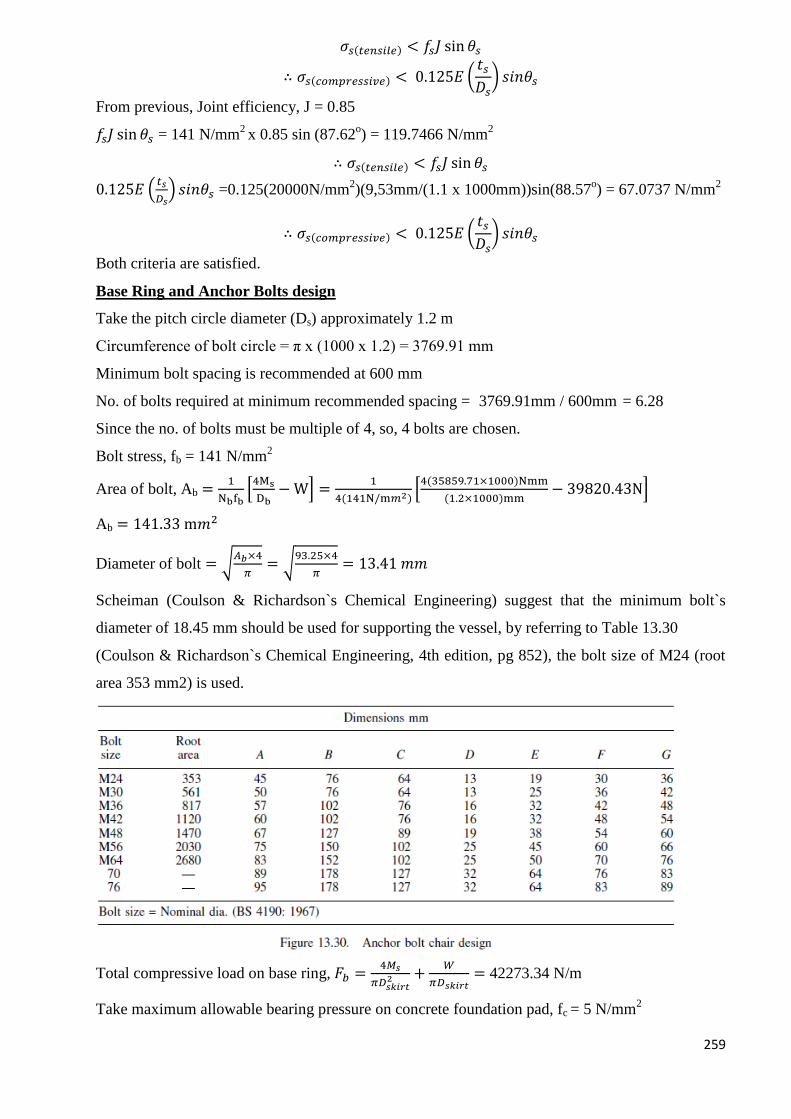
259
𝜎𝑠(𝑡𝑒𝑛𝑠𝑖𝑙𝑒) < 𝑓𝑠𝐽 sin 𝜃𝑠
∴ 𝜎𝑠(𝑐𝑜𝑚𝑝𝑟𝑒𝑠𝑠𝑖𝑣𝑒) < 0.125𝐸 (𝑡𝑠𝐷𝑠
) 𝑠𝑖𝑛𝜃𝑠
From previous, Joint efficiency, J = 0.85
𝑓𝑠𝐽 sin 𝜃𝑠 = 141 N/mm2 x 0.85 sin (87.62
o) = 119.7466 N/mm
2
∴ 𝜎𝑠(𝑡𝑒𝑛𝑠𝑖𝑙𝑒) < 𝑓𝑠𝐽 sin 𝜃𝑠
0.125𝐸 (𝑡𝑠
𝐷𝑠) 𝑠𝑖𝑛𝜃𝑠 =0.125(20000N/mm
2)(9,53mm/(1.1 x 1000mm))sin(88.57
o) = 67.0737 N/mm
2
∴ 𝜎𝑠(𝑐𝑜𝑚𝑝𝑟𝑒𝑠𝑠𝑖𝑣𝑒) < 0.125𝐸 (𝑡𝑠𝐷𝑠
) 𝑠𝑖𝑛𝜃𝑠
Both criteria are satisfied.
Base Ring and Anchor Bolts design
Take the pitch circle diameter (Ds) approximately 1.2 m
Circumference of bolt circle = π x (1000 x 1.2) = 3769.91 mm
Minimum bolt spacing is recommended at 600 mm
No. of bolts required at minimum recommended spacing = 3769.91mm / 600mm = 6.28
Since the no. of bolts must be multiple of 4, so, 4 bolts are chosen.
Bolt stress, fb = 141 N/mm2
Area of bolt, Ab =1
Nbfb[4Ms
Db− W] =
1
4(141N/m𝑚2)[4(35859.71×1000)Nmm
(1.2×1000)mm− 39820.43N]
Ab = 141.33 m𝑚2
Diameter of bolt = √𝐴𝑏×4
𝜋= √
93.25×4
𝜋= 13.41 𝑚𝑚
Scheiman (Coulson & Richardson`s Chemical Engineering) suggest that the minimum bolt`s
diameter of 18.45 mm should be used for supporting the vessel, by referring to Table 13.30
(Coulson & Richardson`s Chemical Engineering, 4th edition, pg 852), the bolt size of M24 (root
area 353 mm2) is used.
Total compressive load on base ring, 𝐹𝑏 =4𝑀𝑠
𝜋𝐷𝑠𝑘𝑖𝑟𝑡2 +
𝑊
𝜋𝐷𝑠𝑘𝑖𝑟𝑡= 42273.34 N/m
Take maximum allowable bearing pressure on concrete foundation pad, fc = 5 N/mm2

260
𝑀𝑖𝑛𝑖𝑚𝑢𝑛 𝑤𝑖𝑑𝑡ℎ 𝑜𝑑 𝑏𝑎𝑠𝑒 𝑟𝑖𝑛𝑔, 𝐿𝑏 =𝐹𝑏
𝑓𝑐=
32758.25 N/m
5 𝑁/𝑚𝑚2= 8.4547 mm
This is the minimum width required; actual width will depend on the chair design.
Let distance from the edge of the skirt to the outer edge of the ring, Lr = 200 mm
Actual width required = Lr + ts +50mm = 200mm + 6mm + 50mm = 259.53 mm
Actual bearing pressure on base, fc' = 𝐹𝑏
𝐴𝑐𝑡𝑢𝑎𝑙 𝑤𝑖𝑑𝑡ℎ=
42273.34 N/m
259.53 𝑚𝑚 = 0.1629 N/mm
2
Let allowable design tressinring material, fr = 140 N/mm2
Maximum thickness, tb =𝐿𝑟√3𝑓′
𝑐
𝑓𝑟= 11.8159𝑚𝑚 ≈ 12𝑚𝑚
Nozzles Design
The Harker equation (1978), modified for SI unit, for the optimum pipe (and nozzle) diameter:
𝐷𝑜𝑝𝑡 = 8.41𝑊0.45
𝜌0.31
where W is mass flow rate (kg.hr) and ρ is density of fluid (kg/m3)
From mass balance spreadsheet,
Stream W (kg/hr) ρ (kg/m3)
Feed Inlet (14) 5656.131 739.6562
Exit Gas (15) 2681.945 731.6309
Exit liquid (16) 22598.22 987.7776
Solvent (28) 27639.06 999.939
For feed inlet:
Dopt = 52.97 mm = 2.09 in.
The nearest standard pipe which is bigger than the optimum is selected.
∴ 3 in. diameter nozzle is used.
For exit gas
Dopt = 37.99 mm = 1.50 in.
The nearest standard pipe which is bigger than the optimum is selected.
∴ 2 in. diameter nozzle is used.
For exit liquid
Dopt = 90.32 mm = 3.56 in.
The nearest standard pipe which is bigger than the optimum is selected.
∴ 4 in. diameter nozzle is used.
For solvent
Dopt = 98.51 mm = 3.88 in.
The nearest standard pipe which is bigger than the optimum is selected.
∴ 4 in. diameter nozzle is used.
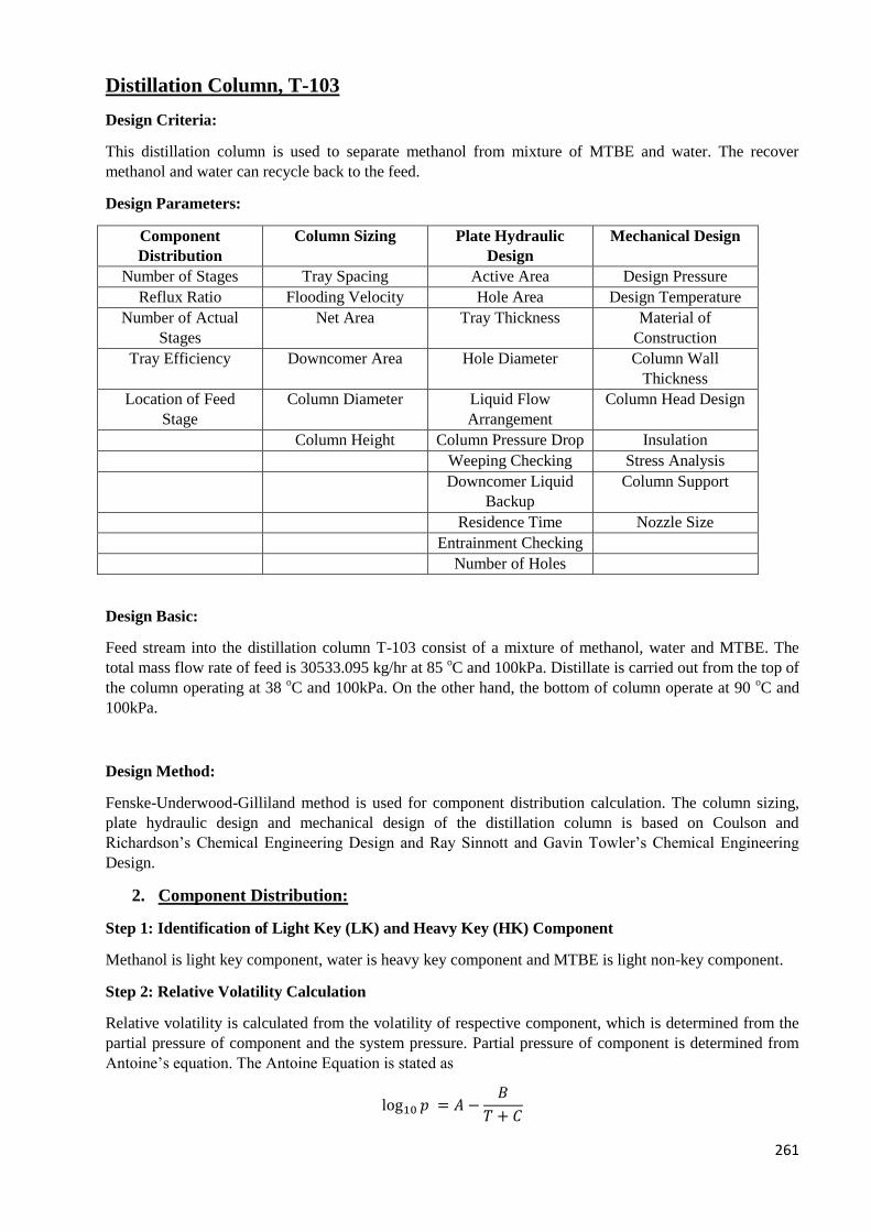
261
Distillation Column, T-103
Design Criteria:
This distillation column is used to separate methanol from mixture of MTBE and water. The recover
methanol and water can recycle back to the feed.
Design Parameters:
Component
Distribution
Column Sizing Plate Hydraulic
Design
Mechanical Design
Number of Stages Tray Spacing Active Area Design Pressure
Reflux Ratio Flooding Velocity Hole Area Design Temperature
Number of Actual
Stages
Net Area Tray Thickness Material of
Construction
Tray Efficiency Downcomer Area Hole Diameter Column Wall
Thickness
Location of Feed
Stage
Column Diameter Liquid Flow
Arrangement
Column Head Design
Column Height Column Pressure Drop Insulation
Weeping Checking Stress Analysis
Downcomer Liquid
Backup
Column Support
Residence Time Nozzle Size
Entrainment Checking
Number of Holes
Design Basic:
Feed stream into the distillation column T-103 consist of a mixture of methanol, water and MTBE. The
total mass flow rate of feed is 30533.095 kg/hr at 85 oC and 100kPa. Distillate is carried out from the top of
the column operating at 38 oC and 100kPa. On the other hand, the bottom of column operate at 90
oC and
100kPa.
Design Method:
Fenske-Underwood-Gilliland method is used for component distribution calculation. The column sizing,
plate hydraulic design and mechanical design of the distillation column is based on Coulson and
Richardson’s Chemical Engineering Design and Ray Sinnott and Gavin Towler’s Chemical Engineering
Design.
2. Component Distribution:
Step 1: Identification of Light Key (LK) and Heavy Key (HK) Component
Methanol is light key component, water is heavy key component and MTBE is light non-key component.
Step 2: Relative Volatility Calculation
Relative volatility is calculated from the volatility of respective component, which is determined from the
partial pressure of component and the system pressure. Partial pressure of component is determined from
Antoine’s equation. The Antoine Equation is stated as
log10 𝑝 = 𝐴 −𝐵
𝑇 + 𝐶
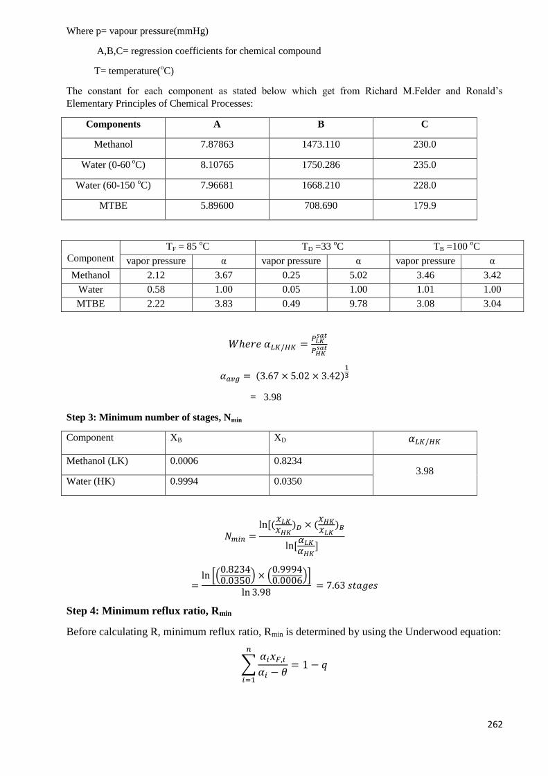
262
Where p= vapour pressure(mmHg)
A,B,C= regression coefficients for chemical compound
T= temperature(oC)
The constant for each component as stated below which get from Richard M.Felder and Ronald’s
Elementary Principles of Chemical Processes:
Components A B C
Methanol 7.87863 1473.110 230.0
Water (0-60 oC) 8.10765 1750.286 235.0
Water (60-150 oC) 7.96681 1668.210 228.0
MTBE 5.89600 708.690 179.9
Component
TF = 85 oC TD =33
oC TB =100
oC
vapor pressure α vapor pressure α vapor pressure α
Methanol 2.12 3.67 0.25 5.02 3.46 3.42
Water 0.58 1.00 0.05 1.00 1.01 1.00
MTBE 2.22 3.83 0.49 9.78 3.08 3.04
𝑊ℎ𝑒𝑟𝑒 𝛼𝐿𝐾/𝐻𝐾 =𝑃𝐿𝐾
𝑠𝑎𝑡
𝑃𝐻𝐾𝑠𝑎𝑡
𝛼𝑎𝑣𝑔 = (3.67 × 5.02 × 3.42)13
= 3.98
Step 3: Minimum number of stages, Nmin
Component XB XD 𝛼𝐿𝐾/𝐻𝐾
Methanol (LK) 0.0006 0.8234 3.98
Water (HK) 0.9994 0.0350
𝑁𝑚𝑖𝑛 =ln[(
𝑥𝐿𝐾𝑥𝐻𝐾
)𝐷 × (𝑥𝐻𝐾𝑥𝐿𝐾
)𝐵
ln[𝛼𝐿𝐾𝛼𝐻𝐾
]
=ln [(
0.82340.0350
) × (0.99940.0006)]
ln 3.98 = 7.63 𝑠𝑡𝑎𝑔𝑒𝑠
Step 4: Minimum reflux ratio, Rmin
Before calculating R, minimum reflux ratio, Rmin is determined by using the Underwood equation:
∑𝛼𝑖𝑥𝐹,𝑖
𝛼𝑖 − 𝜃= 1 − 𝑞
𝑛
𝑖=1
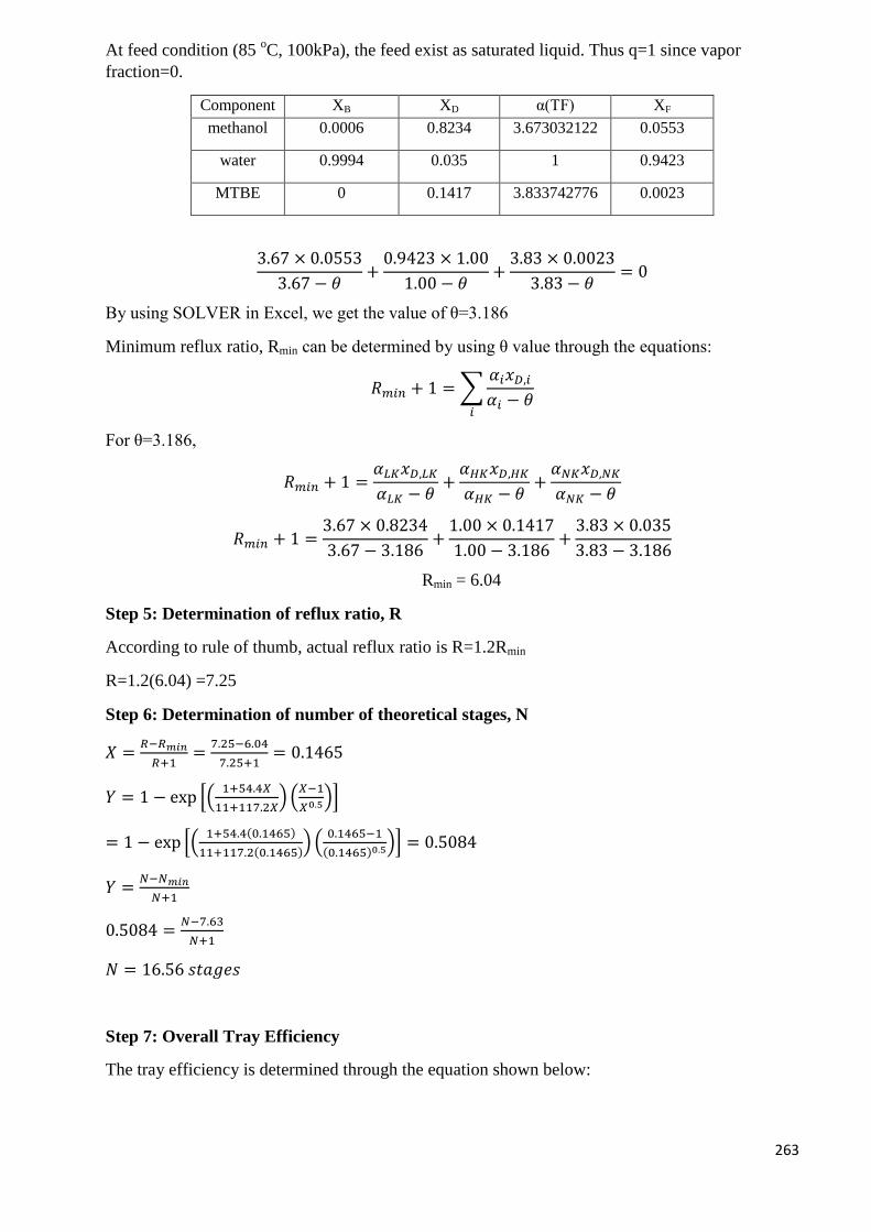
263
At feed condition (85 oC, 100kPa), the feed exist as saturated liquid. Thus q=1 since vapor
fraction=0.
Component XB XD α(TF) XF
methanol 0.0006 0.8234 3.673032122 0.0553
water 0.9994 0.035 1 0.9423
MTBE 0 0.1417 3.833742776 0.0023
3.67 × 0.0553
3.67 − 𝜃+
0.9423 × 1.00
1.00 − 𝜃+
3.83 × 0.0023
3.83 − 𝜃= 0
By using SOLVER in Excel, we get the value of θ=3.186
Minimum reflux ratio, Rmin can be determined by using θ value through the equations:
𝑅𝑚𝑖𝑛 + 1 = ∑𝛼𝑖𝑥𝐷,𝑖
𝛼𝑖 − 𝜃𝑖
For θ=3.186,
𝑅𝑚𝑖𝑛 + 1 =𝛼𝐿𝐾𝑥𝐷,𝐿𝐾
𝛼𝐿𝐾 − 𝜃+
𝛼𝐻𝐾𝑥𝐷,𝐻𝐾
𝛼𝐻𝐾 − 𝜃+
𝛼𝑁𝐾𝑥𝐷,𝑁𝐾
𝛼𝑁𝐾 − 𝜃
𝑅𝑚𝑖𝑛 + 1 =3.67 × 0.8234
3.67 − 3.186+
1.00 × 0.1417
1.00 − 3.186+
3.83 × 0.035
3.83 − 3.186
Rmin = 6.04
Step 5: Determination of reflux ratio, R
According to rule of thumb, actual reflux ratio is R=1.2Rmin
R=1.2(6.04) =7.25
Step 6: Determination of number of theoretical stages, N
𝑋 =𝑅−𝑅𝑚𝑖𝑛
𝑅+1=
7.25−6.04
7.25+1= 0.1465
𝑌 = 1 − exp [(1+54.4𝑋
11+117.2𝑋) (
𝑋−1
𝑋0.5)]
= 1 − exp [(1+54.4(0.1465)
11+117.2(0.1465)) (
0.1465−1
(0.1465)0.5)] = 0.5084
𝑌 =𝑁−𝑁𝑚𝑖𝑛
𝑁+1
0.5084 =𝑁−7.63
𝑁+1
𝑁 = 16.56 𝑠𝑡𝑎𝑔𝑒𝑠
Step 7: Overall Tray Efficiency
The tray efficiency is determined through the equation shown below:
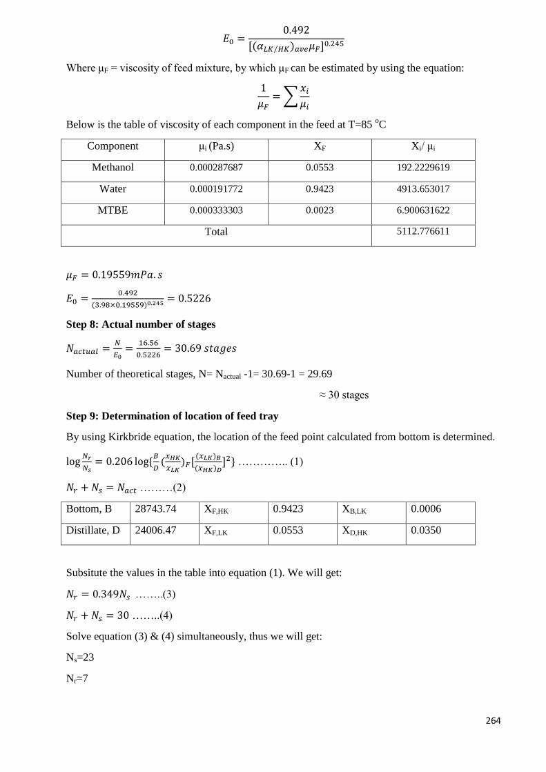
264
𝐸0 =0.492
[(𝛼𝐿𝐾 𝐻𝐾⁄ )𝑎𝑣𝑒𝜇𝐹]0.245
Where μF = viscosity of feed mixture, by which μF can be estimated by using the equation:
1
𝜇𝐹= ∑
𝑥𝑖
𝜇𝑖
Below is the table of viscosity of each component in the feed at T=85 oC
Component μi (Pa.s) XF Xi/ μi
Methanol 0.000287687 0.0553 192.2229619
Water 0.000191772 0.9423 4913.653017
MTBE 0.000333303 0.0023 6.900631622
Total 5112.776611
𝜇𝐹 = 0.19559𝑚𝑃𝑎. 𝑠
𝐸0 =0.492
(3.98×0.19559)0.245 = 0.5226
Step 8: Actual number of stages
𝑁𝑎𝑐𝑡𝑢𝑎𝑙 =𝑁
𝐸0=
16.56
0.5226= 30.69 𝑠𝑡𝑎𝑔𝑒𝑠
Number of theoretical stages, N= Nactual -1= 30.69-1 = 29.69
≈ 30 stages
Step 9: Determination of location of feed tray
By using Kirkbride equation, the location of the feed point calculated from bottom is determined.
log𝑁𝑟
𝑁𝑠= 0.206 log{
𝐵
𝐷(𝑥𝐻𝐾
𝑥𝐿𝐾)𝐹[
(𝑥𝐿𝐾)𝐵
(𝑥𝐻𝐾)𝐷]2} ………….. (1)
𝑁𝑟 + 𝑁𝑠 = 𝑁𝑎𝑐𝑡 ………(2)
Bottom, B 28743.74 XF,HK 0.9423 XB,LK 0.0006
Distillate, D 24006.47 XF,LK 0.0553 XD,HK 0.0350
Subsitute the values in the table into equation (1). We will get:
𝑁𝑟 = 0.349𝑁𝑠 ……..(3)
𝑁𝑟 + 𝑁𝑠 = 30 ……..(4)
Solve equation (3) & (4) simultaneously, thus we will get:
Ns=23
Nr=7
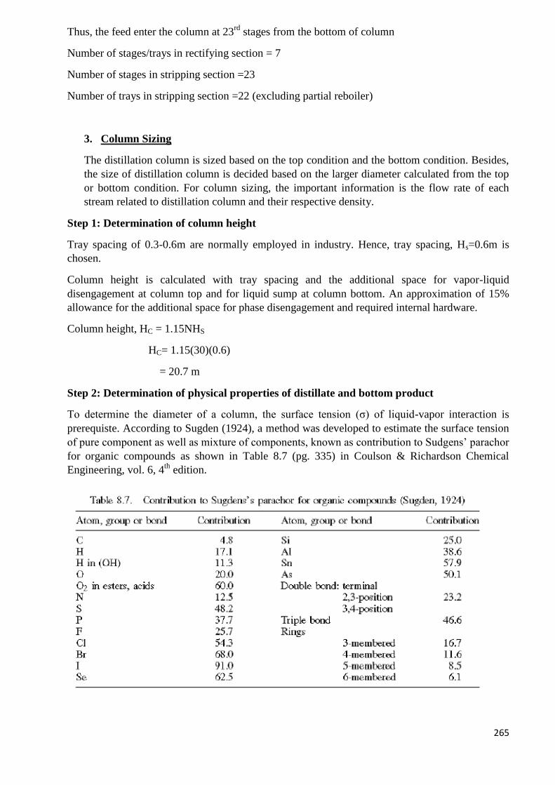
265
Thus, the feed enter the column at 23rd
stages from the bottom of column
Number of stages/trays in rectifying section = 7
Number of stages in stripping section =23
Number of trays in stripping section =22 (excluding partial reboiler)
3. Column Sizing
The distillation column is sized based on the top condition and the bottom condition. Besides,
the size of distillation column is decided based on the larger diameter calculated from the top
or bottom condition. For column sizing, the important information is the flow rate of each
stream related to distillation column and their respective density.
Step 1: Determination of column height
Tray spacing of 0.3-0.6m are normally employed in industry. Hence, tray spacing, Hs=0.6m is
chosen.
Column height is calculated with tray spacing and the additional space for vapor-liquid
disengagement at column top and for liquid sump at column bottom. An approximation of 15%
allowance for the additional space for phase disengagement and required internal hardware.
Column height, HC = 1.15NHS
HC= 1.15(30)(0.6)
= 20.7 m
Step 2: Determination of physical properties of distillate and bottom product
To determine the diameter of a column, the surface tension (σ) of liquid-vapor interaction is
prerequiste. According to Sugden (1924), a method was developed to estimate the surface tension
of pure component as well as mixture of components, known as contribution to Sudgens’ parachor
for organic compounds as shown in Table 8.7 (pg. 335) in Coulson & Richardson Chemical
Engineering, vol. 6, 4th
edition.
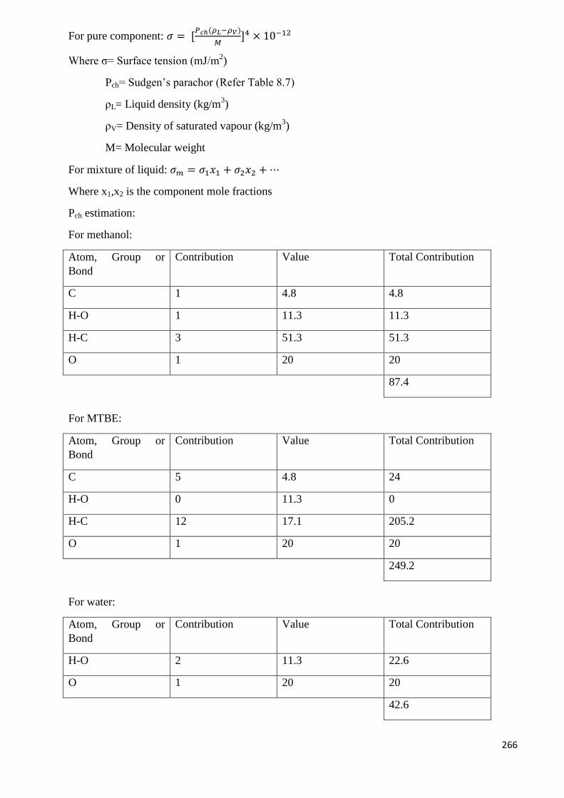
266
For pure component: 𝜎 = [𝑃𝑐ℎ(𝜌𝐿−𝜌𝑉)
𝑀]4 × 10⁻¹²
Where σ= Surface tension (mJ/m2)
Pch= Sudgen’s parachor (Refer Table 8.7)
ρL= Liquid density (kg/m3)
ρV= Density of saturated vapour (kg/m3)
M= Molecular weight
For mixture of liquid: 𝜎𝑚 = 𝜎1𝑥1 + 𝜎2𝑥2 + ⋯
Where x1,x2 is the component mole fractions
Pch estimation:
For methanol:
Atom, Group or
Bond
Contribution Value Total Contribution
C 1 4.8 4.8
H-O 1 11.3 11.3
H-C 3 51.3 51.3
O 1 20 20
87.4
For MTBE:
Atom, Group or
Bond
Contribution Value Total Contribution
C 5 4.8 24
H-O 0 11.3 0
H-C 12 17.1 205.2
O 1 20 20
249.2
For water:
Atom, Group or
Bond
Contribution Value Total Contribution
H-O 2 11.3 22.6
O 1 20 20
42.6
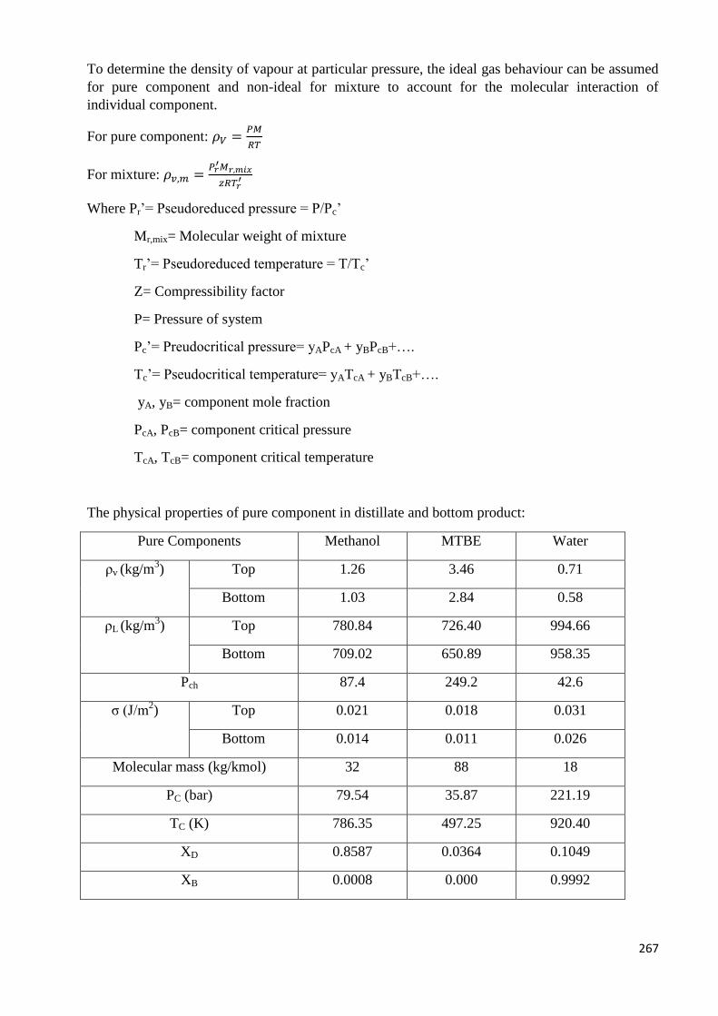
267
To determine the density of vapour at particular pressure, the ideal gas behaviour can be assumed
for pure component and non-ideal for mixture to account for the molecular interaction of
individual component.
For pure component: 𝜌𝑉 =𝑃𝑀
𝑅𝑇
For mixture: 𝜌𝑣,𝑚 =𝑃𝑟
′𝑀𝑟,𝑚𝑖𝑥
𝑧𝑅𝑇𝑟′
Where Pr’= Pseudoreduced pressure = P/Pc’
Mr,mix= Molecular weight of mixture
Tr’= Pseudoreduced temperature = T/Tc’
Z= Compressibility factor
P= Pressure of system
Pc’= Preudocritical pressure= yAPcA + yBPcB+….
Tc’= Pseudocritical temperature= yATcA + yBTcB+….
yA, yB= component mole fraction
PcA, PcB= component critical pressure
TcA, TcB= component critical temperature
The physical properties of pure component in distillate and bottom product:
Pure Components Methanol MTBE Water
ρv (kg/m3) Top 1.26 3.46 0.71
Bottom 1.03 2.84 0.58
ρL (kg/m3) Top 780.84 726.40 994.66
Bottom 709.02 650.89 958.35
Pch 87.4 249.2 42.6
σ (J/m2) Top 0.021 0.018 0.031
Bottom 0.014 0.011 0.026
Molecular mass (kg/kmol) 32 88 18
PC (bar) 79.54 35.87 221.19
TC (K) 786.35 497.25 920.40
XD 0.8587 0.0364 0.1049
XB 0.0008 0.000 0.9992
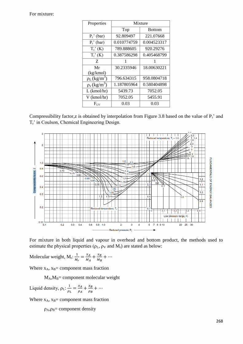
268
For mixture:
Properties Mixture
Top Bottom
Pc’ (bar) 92.809497 221.07668
Pr’ (bar) 0.010774759 0.004523317
Tc’ (K) 789.888605 920.29276
Tr’ (K) 0.387586298 0.405468799
Z 1 1
Mr
(kg/kmol)
30.2335946 18.00630221
ρL (kg/m3) 796.634315 958.0804718
ρv (kg/m3) 1.187805964 0.580404898
L (kmol/hr) 5439.73 7052.05
V (kmol/hr) 7052.05 5455.91
FLV 0.03 0.03
Compressibility factor,z is obtained by interpolation from Figure 3.8 based on the value of Pr’ and
Tr’ in Coulson, Chemical Engineering Design.
For mixture in both liquid and vapour in overhead and bottom product, the methods used to
estimate the physical properties (ρL, ρV and Mr) are stated as below:
Molecular weight, Mr: 1
𝑀𝑟=
𝑥𝐴
𝑀𝐴+
𝑥𝐵
𝑀𝐵+ ⋯
Where xA, xB= component mass fraction
MA,MB= component molecular weight
Liquid density, ρL: 1
𝜌𝐿=
𝑥𝐴
𝜌𝐴+
𝑥𝐵
𝜌𝐵+ ⋯
Where xA, xB= component mass fraction
ρA,ρB= component density
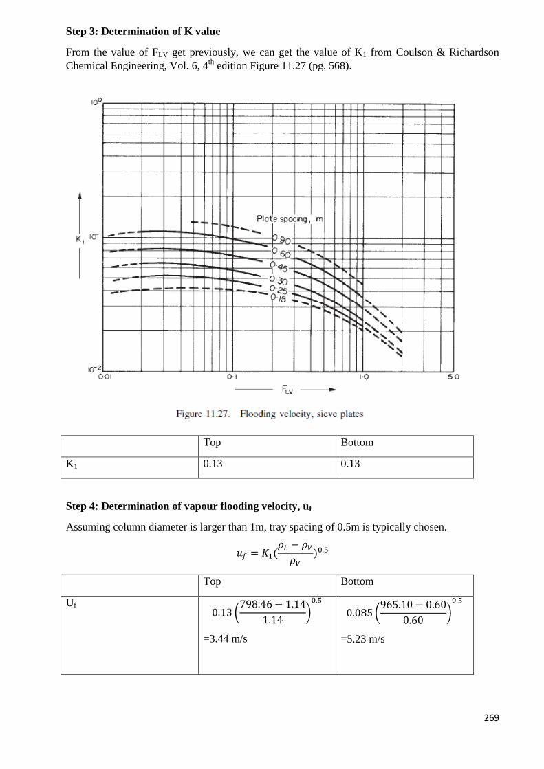
269
Step 3: Determination of K value
From the value of FLV get previously, we can get the value of K1 from Coulson & Richardson
Chemical Engineering, Vol. 6, 4th
edition Figure 11.27 (pg. 568).
Top Bottom
K1 0.13 0.13
Step 4: Determination of vapour flooding velocity, uf
Assuming column diameter is larger than 1m, tray spacing of 0.5m is typically chosen.
𝑢𝑓 = 𝐾1(𝜌𝐿 − 𝜌𝑉
𝜌𝑉)0.5
Top Bottom
Uf
0.13 (798.46 − 1.14
1.14)0.5
=3.44 m/s
0.085 (965.10 − 0.60
0.60)0.5
=5.23 m/s
270
Step 5: Determination of actual vapour velocity, uV
Assume 50% flooding for column operation
𝑢𝑉 = 0.5𝑢𝑓
Top Bottom
UV 0.5(3.44 m/s)= 1.72 m/s 0.5(5.23 m/s)= 2.61 m/s
Step 6: Determination of volumetric flow rate, �̇�
�̇� =𝑣 (
𝑘𝑚𝑜𝑙ℎ𝑟
) × 𝑀𝑟 (𝑘𝑔
𝑘𝑚𝑜𝑙)
𝜌𝑉 (𝑘𝑔𝑚3) ×
3600𝑠ℎ𝑟
Top Bottom
�̇� 7052.05×29.41
1.14×3600
=50.67 m3/s
5455.91×18.00
0.60×3600
=45.76 m3/s
Step 7: Determination of net column area, An
𝐴𝑛 =�̇�
𝑢𝑣
Top Bottom
An 50.67/1.72
=29.44 m2
45.76/2.61
=17.50 m2
Step 8: Determination of cross sectional area, Ac
Assume downcomer occupies 20% of column cross sectional area, 𝐴𝑐 =𝐴𝑛
0.8
Top Bottom
Ac 29.44/0.8
=36.80 m2
17.50/0.8
=21.88 m2
271
Step 9: Determination of cross sectional area of downcomer, Ad
𝐴𝑑 = 𝐴𝑐 − 𝐴𝑛
Top Bottom
Ad 36.80-29.44
=7.36 m2
21.88-17.50
=4.38 m2
Step 10: Determination of column diameter, Dc
𝐷𝑐 = √4𝐴𝑐
𝜋
Top Bottom
Dc √
4𝐴𝑐
𝜋
=√4(36.80)
𝜋
=6.84 m
√4𝐴𝑐
𝜋
=√4(21.88)
𝜋
=5.28 m
Since limiting vapour condition occurs at the top of column, so the column inner diameter is taken
as 6.84m. Since the column diameter is larger than 1m, the tray spacing of 0.6 m is justified.
There are two limitations on the design conditions of distillation column, which are the column
height and height-to-diameter ratio. The general guidelines are column height, Hc < 54m and the
height-to-diameter ratio, Hc/Dc < 30 [James M.Douglas, 1988. “Conceptual Design of Chemical
Processes”, McGraw Hill, pg 457]
Previously, we calculated Hc = 20.7 m which is less than 54m. Thus, it is acceptable. On the other
hands, ratio Hc/Dc = 20.7/ 6.84= 3.03 (<30). Hence, it is acceptable.
4. Plate hydraulic design
Consider the preliminary specification of column T-103 on the basis of top section.
Column diameter, Dc= 6.84 m
Column area, Ac=36.80 m2
Net area, An= 29.44 m2
Downcomer area, Ad= 7.36 m
2
Step 1: Provisional plate design
Active area, 𝐴𝑎 = 𝐴𝑐 − 2𝐴𝑑 = 36.80 − 2(7.36) = 22.08𝑚2
Assume all active holes take 6% of active area.
Hole area, 𝐴ℎ = 0.06𝐴𝑎 = 0.06(22.08) = 1.32 𝑚2
Hole size/diameter:
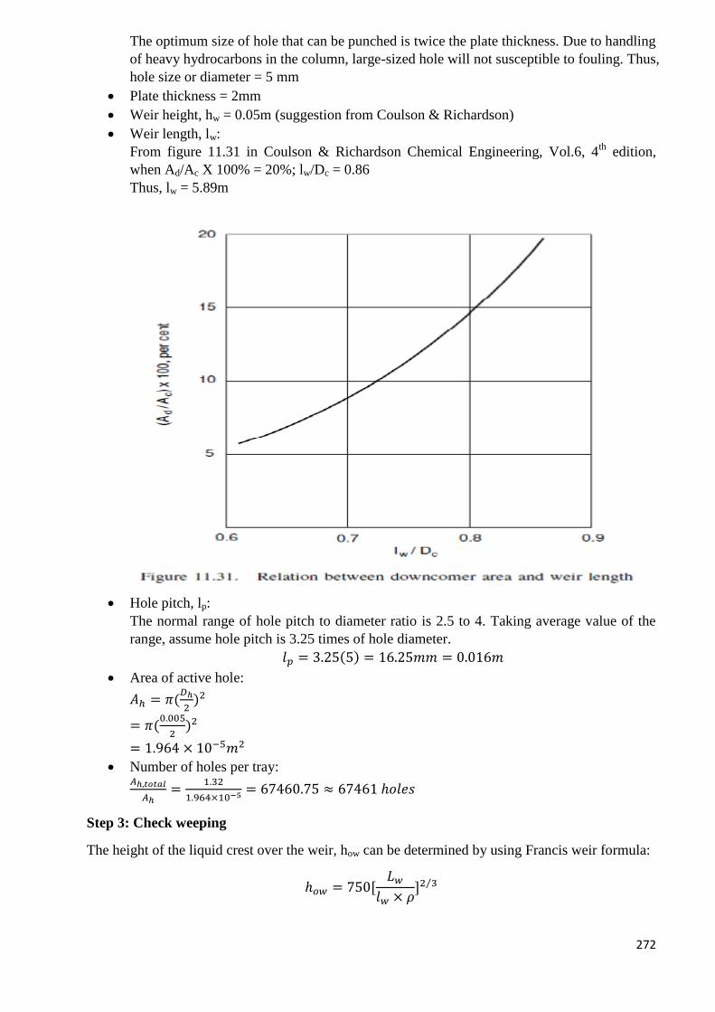
272
The optimum size of hole that can be punched is twice the plate thickness. Due to handling
of heavy hydrocarbons in the column, large-sized hole will not susceptible to fouling. Thus,
hole size or diameter = 5 mm
Plate thickness = 2mm
Weir height, hw = 0.05m (suggestion from Coulson & Richardson)
Weir length, lw:
From figure 11.31 in Coulson & Richardson Chemical Engineering, Vol.6, 4th
edition,
when Ad/Ac X 100% = 20%; lw/Dc = 0.86
Thus, lw = 5.89m
Hole pitch, lp:
The normal range of hole pitch to diameter ratio is 2.5 to 4. Taking average value of the
range, assume hole pitch is 3.25 times of hole diameter.
𝑙𝑝 = 3.25(5) = 16.25𝑚𝑚 = 0.016𝑚
Area of active hole:
𝐴ℎ = 𝜋(𝐷ℎ
2)2
= 𝜋(0.005
2)2
= 1.964 × 10⁻⁵𝑚2
Number of holes per tray: 𝐴ℎ,𝑡𝑜𝑡𝑎𝑙
𝐴ℎ=
1.32
1.964×10−5 = 67460.75 ≈ 67461 ℎ𝑜𝑙𝑒𝑠
Step 3: Check weeping
The height of the liquid crest over the weir, how can be determined by using Francis weir formula:
ℎ𝑜𝑤 = 750[𝐿𝑤
𝑙𝑤 × 𝜌]2 3⁄
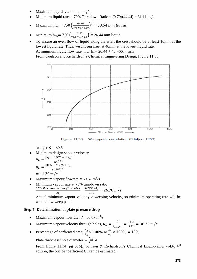
273
Maximum liquid rate = 44.44 kg/s
Minimum liquid rate at 70% Turndown Ratio = (0.70)(44.44) = 31.11 kg/s
Maximum how = 750 (44.44
796.63×5.89)
2
3= 33.54 𝑚𝑚 𝑙𝑖𝑞𝑢𝑖𝑑
Minimum how= 750 (31.11
796.63×5.89)
2
3= 26.44 mm liquid
To ensure an even flow of liquid along the wier, the crest should be at least 10mm at the
lowest liquid rate. Thus, we chosen crest at 40mm at the lowest liquid rate.
At minimum liquid flow rate, how+hw= 26.44 + 40 =66.44mm
From Coulson and Richardson’s Chemical Engineering Design, Figure 11.30,
we get K2= 30.5
Minimum design vapour velocity,
𝑢ℎ =[𝐾2−0.90(25.4−𝑑ℎ)]
(𝜌𝑣)0.5
𝑢ℎ =[30.5−0.90(25.4−5)]
(1.187)0.5
= 11.39 𝑚/𝑠
Maximum vapour flowrate = 50.67 m3/s
Minimum vapour rate at 70% turndown ratio: 0.70(𝑀𝑎𝑥𝑖𝑚𝑢𝑚 𝑣𝑎𝑝𝑜𝑟 𝑓𝑙𝑜𝑤𝑟𝑎𝑡𝑒)
𝐴ℎ=
0.7(50.67)
1.32= 26.78 𝑚/𝑠
Actual minimum vapour velocity > weeping velocity, so minimum operating rate will be
well below weep point
Step 4: Determination of plate pressure drop
Maximum vapour flowrate, �̇�= 50.67 m3/s
Maximum vapour velocity through holes, 𝑢ℎ =�̇�
𝐴ℎ,𝑡𝑜𝑡𝑎𝑙=
50.67
1.32= 38.25 𝑚/𝑠
Percentage of perforated area, 𝐴ℎ
𝐴𝑝× 100% ≈
𝐴ℎ
𝐴𝑎× 100% = 10%
Plate thickness/ hole diameter =2
5=0.4
From figure 11.34 (pg 576), Coulson & Richardson’s Chemical Engineering, vol.6, 4th
edition, the orifice coefficient Co can be estimated.
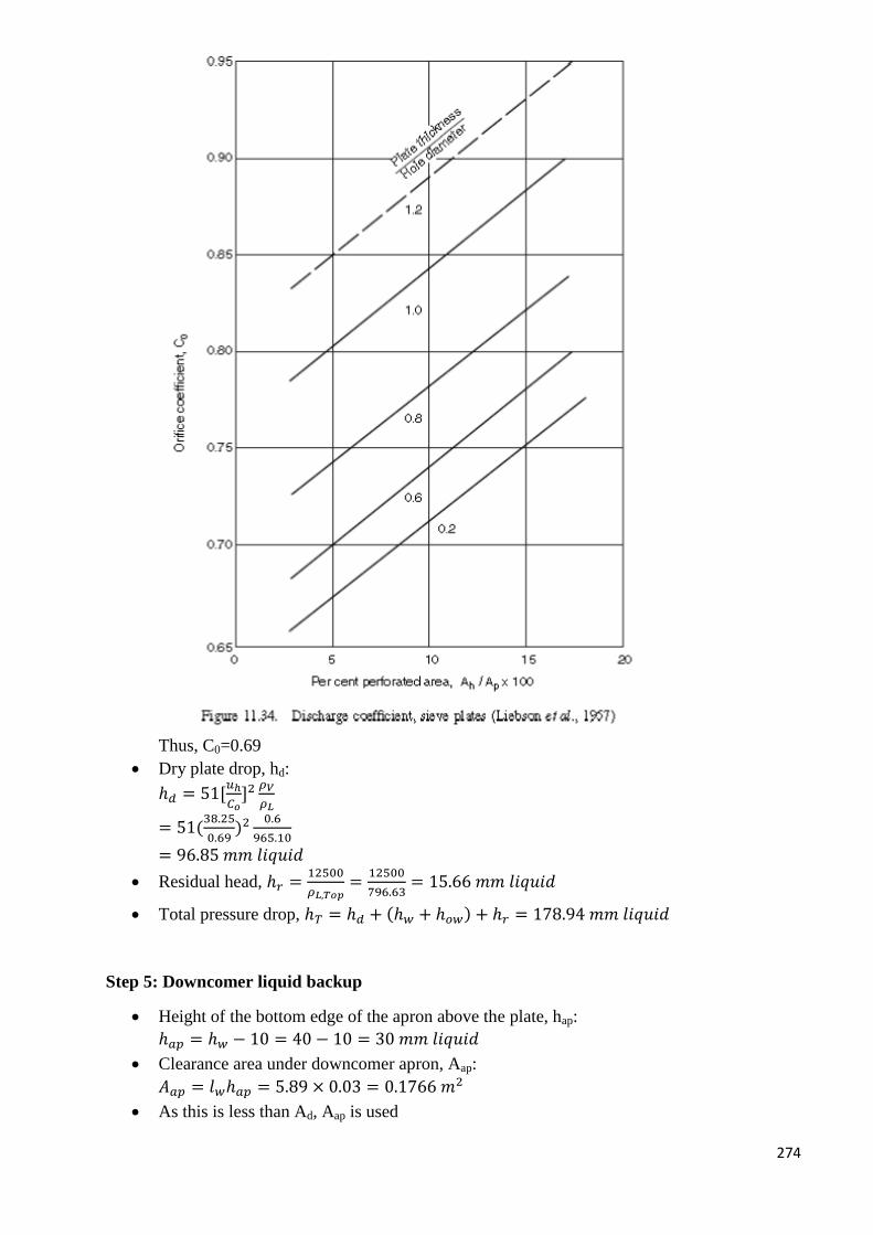
274
Thus, C0=0.69
Dry plate drop, hd:
ℎ𝑑 = 51[𝑢ℎ
𝐶𝑜]2
𝜌𝑉
𝜌𝐿
= 51(38.25
0.69)2 0.6
965.10
= 96.85 𝑚𝑚 𝑙𝑖𝑞𝑢𝑖𝑑
Residual head, ℎ𝑟 =12500
𝜌𝐿,𝑇𝑜𝑝=
12500
796.63= 15.66 𝑚𝑚 𝑙𝑖𝑞𝑢𝑖𝑑
Total pressure drop, ℎ𝑇 = ℎ𝑑 + (ℎ𝑤 + ℎ𝑜𝑤) + ℎ𝑟 = 178.94 𝑚𝑚 𝑙𝑖𝑞𝑢𝑖𝑑
Step 5: Downcomer liquid backup
Height of the bottom edge of the apron above the plate, hap:
ℎ𝑎𝑝 = ℎ𝑤 − 10 = 40 − 10 = 30 𝑚𝑚 𝑙𝑖𝑞𝑢𝑖𝑑
Clearance area under downcomer apron, Aap:
𝐴𝑎𝑝 = 𝑙𝑤ℎ𝑎𝑝 = 5.89 × 0.03 = 0.1766 𝑚2
As this is less than Ad, Aap is used
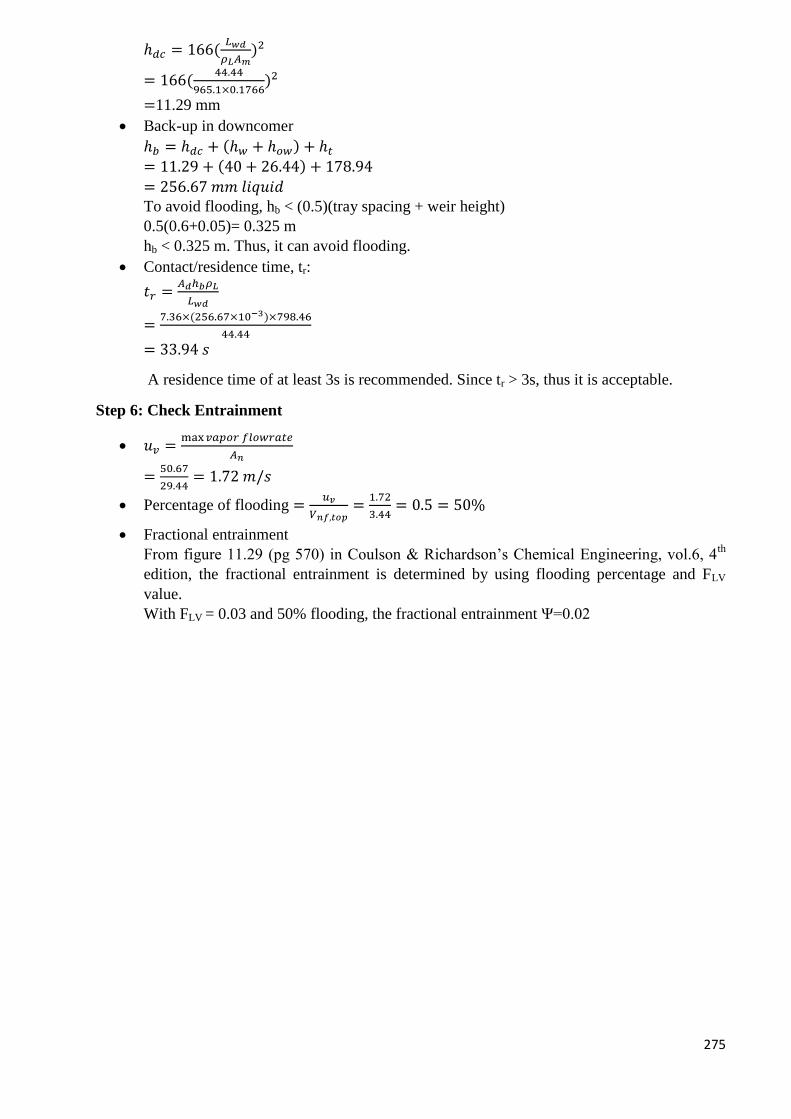
275
ℎ𝑑𝑐 = 166(𝐿𝑤𝑑
𝜌𝐿𝐴𝑚)2
= 166(44.44
965.1×0.1766)2
=11.29 mm
Back-up in downcomer
ℎ𝑏 = ℎ𝑑𝑐 + (ℎ𝑤 + ℎ𝑜𝑤) + ℎ𝑡
= 11.29 + (40 + 26.44) + 178.94
= 256.67 𝑚𝑚 𝑙𝑖𝑞𝑢𝑖𝑑
To avoid flooding, hb < (0.5)(tray spacing + weir height)
0.5(0.6+0.05)= 0.325 m
hb < 0.325 m. Thus, it can avoid flooding.
Contact/residence time, tr:
𝑡𝑟 =𝐴𝑑ℎ𝑏𝜌𝐿
𝐿𝑤𝑑
=7.36×(256.67×10−3)×798.46
44.44
= 33.94 𝑠
A residence time of at least 3s is recommended. Since tr > 3s, thus it is acceptable.
Step 6: Check Entrainment
𝑢𝑣 =max𝑣𝑎𝑝𝑜𝑟 𝑓𝑙𝑜𝑤𝑟𝑎𝑡𝑒
𝐴𝑛
=50.67
29.44= 1.72 𝑚/𝑠
Percentage of flooding =𝑢𝑣
𝑉𝑛𝑓,𝑡𝑜𝑝=
1.72
3.44= 0.5 = 50%
Fractional entrainment
From figure 11.29 (pg 570) in Coulson & Richardson’s Chemical Engineering, vol.6, 4th
edition, the fractional entrainment is determined by using flooding percentage and FLV
value.
With FLV = 0.03 and 50% flooding, the fractional entrainment Ψ=0.02
276
The entrainment is below 0.1, thus it is acceptable.
5. Mechanical Design
Step 1: Design Pressure
The operating pressure of the column is 100kPa. However, there is quite a lot of number of plates
and lead to a significant of pressure drop. It is predicted that pressure at bottom of the column will
be higher. Therefore, an extra 10% of pressure will be considered in mechanical design.
Design pressure, Pi = 110kPa
Step 2: Design temperature
Feed temperature, TF =85 oC
Distillate temperature, TD =38 oC
Bottom temperature, TB =90 oC
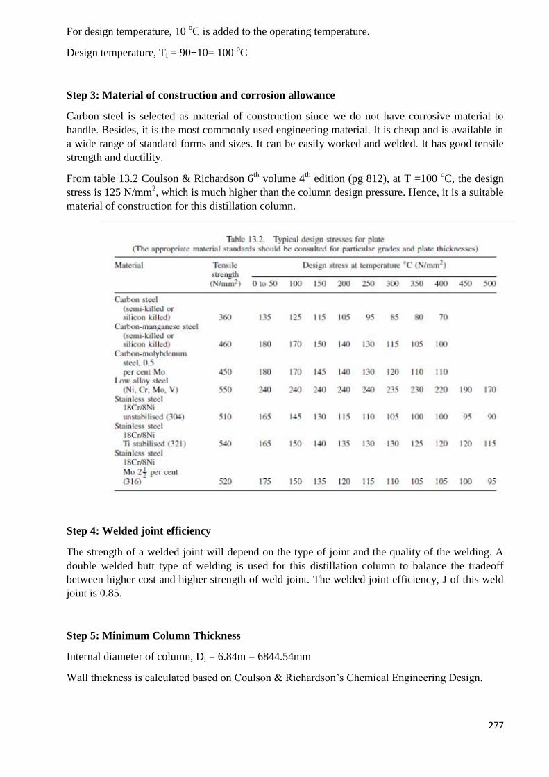
277
For design temperature, 10 oC is added to the operating temperature.
Design temperature, Ti = 90+10= 100 oC
Step 3: Material of construction and corrosion allowance
Carbon steel is selected as material of construction since we do not have corrosive material to
handle. Besides, it is the most commonly used engineering material. It is cheap and is available in
a wide range of standard forms and sizes. It can be easily worked and welded. It has good tensile
strength and ductility.
From table 13.2 Coulson & Richardson 6th
volume 4th
edition (pg 812), at T =100 oC, the design
stress is 125 N/mm2, which is much higher than the column design pressure. Hence, it is a suitable
material of construction for this distillation column.
Step 4: Welded joint efficiency
The strength of a welded joint will depend on the type of joint and the quality of the welding. A
double welded butt type of welding is used for this distillation column to balance the tradeoff
between higher cost and higher strength of weld joint. The welded joint efficiency, J of this weld
joint is 0.85.
Step 5: Minimum Column Thickness
Internal diameter of column, Di = 6.84m = 6844.54mm
Wall thickness is calculated based on Coulson & Richardson’s Chemical Engineering Design.
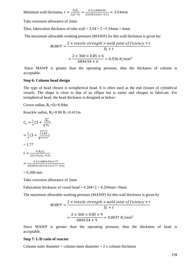
278
Minimum wall thickness, 𝑡 =𝑃𝑖𝐷𝑖
2𝐽𝑓−𝑃𝑖=
0.11×6844.54
2(0.85)(125)−0.11= 3.54𝑚𝑚
Take corrosion allowance of 2mm.
Thus, fabrication thickness of tube wall = 3.54 + 2 =5.54mm ≈ 6mm
The maximum allowable working pressure (MAWP) for this wall thickness is given by:
𝑀𝐴𝑊𝑃 =2 × 𝑡𝑒𝑛𝑠𝑖𝑙𝑒 𝑠𝑡𝑟𝑒𝑛𝑔𝑡ℎ × 𝑤𝑒𝑙𝑑 𝑗𝑜𝑖𝑛𝑡 𝑒𝑓𝑓𝑖𝑐𝑖𝑒𝑛𝑐𝑦 × 𝑡
𝐷𝑖 + 𝑡
=2 × 360 × 0.85 × 6
6844.54 + 6= 0.536 𝑁/𝑚𝑚2
Since MAWP is greater than the operating pressure, thus the thickness of column is
acceptable.
Step 6: Column head design
The type of head chosen is torispherical head. It is often used as the end closure of cylindrical
vessels. The shape is close to that of an ellipse but is easier and cheaper to fabricate. For
torispherical head, the head thickness is designed as below:
Crown radius, Rc=Di=6.84m
Knuckle radius, Rk=0.06 Rc=0.411m
𝐶𝑠 =1
4(3 + √
𝑅𝑐
𝑅𝑘)
=1
4(3 + √
6.84
0.411)
= 1.77
𝑡 =𝑃𝑖𝑅𝑐𝐶𝑠
2𝑓𝐽+𝑃𝑖(𝐶𝑠−0.2)
=0.11×6844.54×1.77
2(0.85)(125)+0.11(1.77−0.2)
= 6.268 mm
Take corrosion allowance of 2mm.
Fabrication thickness of vessel head = 6.268+2 = 8.268mm ≈9mm
The maximum allowable working pressure (MAWP) for this wall thickness is given by
𝑀𝐴𝑊𝑃 =2 × 𝑡𝑒𝑛𝑠𝑖𝑙𝑒 𝑠𝑡𝑟𝑒𝑛𝑔𝑡ℎ × 𝑤𝑒𝑙𝑑 𝑗𝑜𝑖𝑛𝑡 𝑒𝑓𝑓𝑖𝑐𝑖𝑒𝑛𝑐𝑦 × 𝑡
𝐷𝑖 + 𝑡
=2 × 360 × 0.85 × 9
6844.54 + 9= 0.8037 𝑁/𝑚𝑚2
Since MAWP is greater than the operating pressure, thus the thickness of head is
acceptable.
Step 7: L/D ratio of reactor
Column outer diameter = column inner diameter + 2 x column thickness
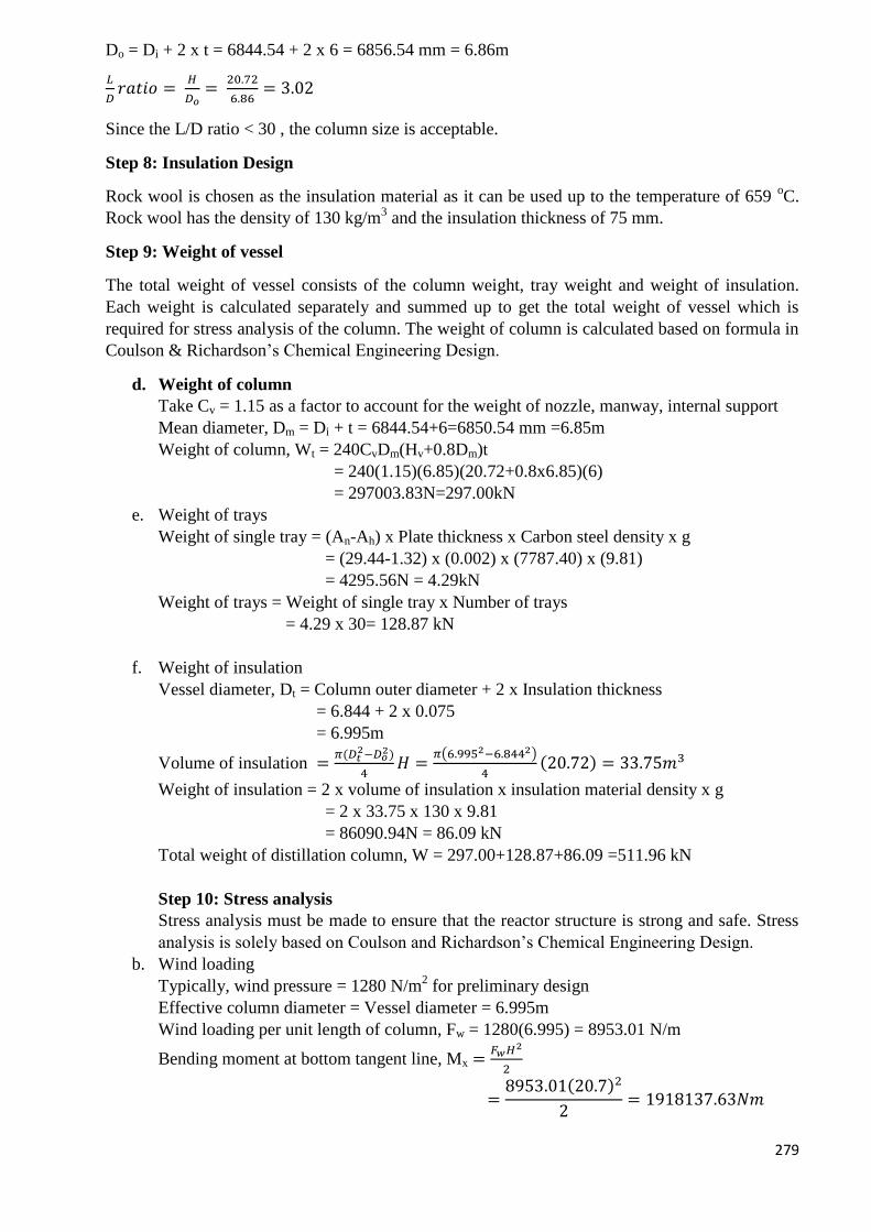
279
Do = Di + 2 x t = 6844.54 + 2 x 6 = 6856.54 mm = 6.86m
𝐿
𝐷𝑟𝑎𝑡𝑖𝑜 =
𝐻
𝐷𝑜=
20.72
6.86= 3.02
Since the L/D ratio < 30 , the column size is acceptable.
Step 8: Insulation Design
Rock wool is chosen as the insulation material as it can be used up to the temperature of 659 oC.
Rock wool has the density of 130 kg/m3 and the insulation thickness of 75 mm.
Step 9: Weight of vessel
The total weight of vessel consists of the column weight, tray weight and weight of insulation.
Each weight is calculated separately and summed up to get the total weight of vessel which is
required for stress analysis of the column. The weight of column is calculated based on formula in
Coulson & Richardson’s Chemical Engineering Design.
d. Weight of column
Take Cv = 1.15 as a factor to account for the weight of nozzle, manway, internal support
Mean diameter, Dm = Di + t = 6844.54+6=6850.54 mm =6.85m
Weight of column, Wt = 240CvDm(Hv+0.8Dm)t
= 240(1.15)(6.85)(20.72+0.8x6.85)(6)
= 297003.83N=297.00kN
e. Weight of trays
Weight of single tray = (An-Ah) x Plate thickness x Carbon steel density x g
= (29.44-1.32) x (0.002) x (7787.40) x (9.81)
= 4295.56N = 4.29kN
Weight of trays = Weight of single tray x Number of trays
= 4.29 x 30= 128.87 kN
f. Weight of insulation
Vessel diameter, Dt = Column outer diameter + 2 x Insulation thickness
= 6.844 + 2 x 0.075
= 6.995m
Volume of insulation =𝜋(𝐷𝑡
2−𝐷𝑜2)
4𝐻 =
𝜋(6.9952−6.8442)
4(20.72) = 33.75𝑚3
Weight of insulation = 2 x volume of insulation x insulation material density x g
= 2 x 33.75 x 130 x 9.81
= 86090.94N = 86.09 kN
Total weight of distillation column, W = 297.00+128.87+86.09 =511.96 kN
Step 10: Stress analysis
Stress analysis must be made to ensure that the reactor structure is strong and safe. Stress
analysis is solely based on Coulson and Richardson’s Chemical Engineering Design.
b. Wind loading
Typically, wind pressure = 1280 N/m2 for preliminary design
Effective column diameter = Vessel diameter = 6.995m
Wind loading per unit length of column, Fw = 1280(6.995) = 8953.01 N/m
Bending moment at bottom tangent line, Mx =𝐹𝑤𝐻2
2
=8953.01(20.7)2
2= 1918137.63𝑁𝑚
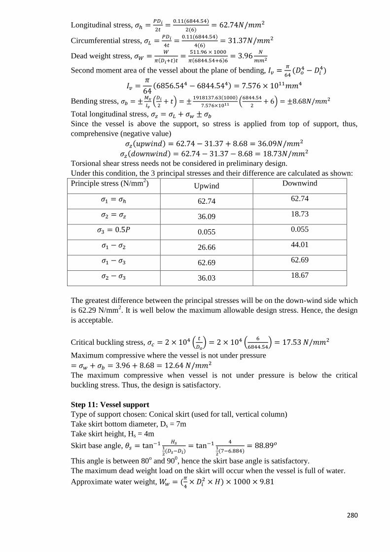
280
Longitudinal stress, 𝜎ℎ =𝑃𝐷𝑖
2𝑡=
0.11(6844.54)
2(6)= 62.74𝑁/𝑚𝑚2
Circumferential stress, 𝜎𝐿 =𝑃𝐷𝑖
4𝑡=
0.11(6844.54)
4(6)= 31.37𝑁/𝑚𝑚2
Dead weight stress, 𝜎𝑊 =𝑊
𝜋(𝐷𝑖+𝑡)𝑡=
511.96 × 1000
𝜋(6844.54+6)6= 3.96
𝑁
𝑚𝑚2
Second moment area of the vessel about the plane of bending, 𝐼𝑣 =𝜋
64(𝐷𝑜
4 − 𝐷𝑖4)
𝐼𝑣 =𝜋
64(6856.544 − 6844.544) = 7.576 × 10¹¹𝑚𝑚4
Bending stress, 𝜎𝑏 = ±𝑀𝑥
𝐼𝑣(𝐷𝑖
2+ 𝑡) = ±
1918137.63(1000)
7.576×10¹¹ (6844.54
2+ 6) = ±8.68𝑁/𝑚𝑚2
Total longitudinal stress, 𝜎𝑧 = 𝜎𝐿 + 𝜎𝑤 ± 𝜎𝑏
Since the vessel is above the support, so stress is applied from top of support, thus,
comprehensive (negative value)
𝜎𝑧(𝑢𝑝𝑤𝑖𝑛𝑑) = 62.74 − 31.37 + 8.68 = 36.09𝑁/𝑚𝑚2
𝜎𝑧(𝑑𝑜𝑤𝑛𝑤𝑖𝑛𝑑) = 62.74 − 31.37 − 8.68 = 18.73𝑁/𝑚𝑚2
Torsional shear stress needs not be considered in preliminary design.
Under this condition, the 3 principal stresses and their difference are calculated as shown:
Principle stress (N/mm2) Upwind Downwind
𝜎1 = 𝜎ℎ 62.74 62.74
𝜎2 = 𝜎𝑧 36.09 18.73
𝜎3 = 0.5𝑃 0.055 0.055
𝜎1 − 𝜎2 26.66 44.01
𝜎1 − 𝜎3 62.69 62.69
𝜎2 − 𝜎3 36.03 18.67
The greatest difference between the principal stresses will be on the down-wind side which
is 62.29 N/mm2. It is well below the maximum allowable design stress. Hence, the design
is acceptable.
Critical buckling stress, 𝜎𝑐 = 2 × 10⁴ (𝑡
𝐷𝑜) = 2 × 10⁴ (
6
6844.54) = 17.53 𝑁/𝑚𝑚2
Maximum compressive where the vessel is not under pressure
= 𝜎𝑤 + 𝜎𝑏 = 3.96 + 8.68 = 12.64 𝑁/𝑚𝑚2
The maximum compressive when vessel is not under pressure is below the critical
buckling stress. Thus, the design is satisfactory.
Step 11: Vessel support
Type of support chosen: Conical skirt (used for tall, vertical column)
Take skirt bottom diameter, Ds = 7m
Take skirt height, Hs = 4m
Skirt base angle, 𝜃𝑠 = tan−1 𝐻𝑠1
2(𝐷𝑠−𝐷𝑖)
= tan−1 41
2(7−6.884)
= 88.89𝑜
This angle is between 80o and 90
0, hence the skirt base angle is satisfactory.
The maximum dead weight load on the skirt will occur when the vessel is full of water.
Approximate water weight, 𝑊𝑤 = (𝜋
4× 𝐷𝑖
2 × 𝐻) × 1000 × 9.81
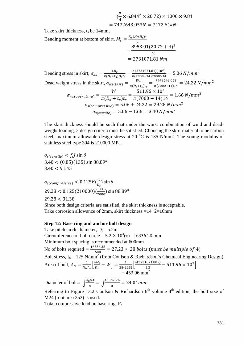
281
= (𝜋
4× 6.8442 × 20.72) × 1000 × 9.81
= 7472643.053𝑁 = 7472.64𝑘𝑁
Take skirt thickness, ts be 14mm,
Bending moment at bottom of skirt, 𝑀𝑠 =𝐹𝑤(𝐻+𝐻𝑠)
2
2
=8953.01(20.72 + 4)2
2
= 2731071.81 𝑁𝑚
Bending stress in skirt, 𝜎𝑏𝑠 =4𝑀𝑠
𝜋(𝐷𝑠+𝑡𝑠)𝐷𝑠𝑡𝑠=
4(2731071.81)(103)
𝜋(7000+14)7000×14= 5.06 𝑁/𝑚𝑚2
Dead weight stress in the skirt, 𝜎𝑤𝑠(𝑡𝑒𝑠𝑡) =𝑊𝑤
𝜋(𝐷𝑠+𝑡𝑠)𝑡𝑠=
7472643.053
𝜋(7000+14)14= 24.22 𝑁/𝑚𝑚2
𝜎𝑤𝑠(𝑜𝑝𝑒𝑟𝑎𝑡𝑖𝑛𝑔) =𝑊
𝜋(𝐷𝑠 + 𝑡𝑠)𝑡𝑠=
511.96 × 10³
𝜋(7000 + 14)14= 1.66 𝑁/𝑚𝑚2
𝜎𝑠(𝑐𝑜𝑚𝑝𝑟𝑒𝑠𝑠𝑖𝑣𝑒) = 5.06 + 24.22 = 29.28 𝑁/𝑚𝑚2
𝜎𝑠(𝑡𝑒𝑛𝑠𝑖𝑙𝑒) = 5.06 − 1.66 = 3.40 𝑁/𝑚𝑚2
The skirt thickness should be such that under the worst combination of wind and dead-
weight loading, 2 design criteria must be satisfied. Choosing the skirt material to be carbon
steel, maximum allowable design stress at 20 oC is 135 N/mm
2. The young modulus of
stainless steel type 304 is 210000 MPa.
𝜎𝑠(𝑡𝑒𝑛𝑠𝑖𝑙𝑒) < 𝑓𝑠𝐽 sin 𝜃
3.40 < (0.85)(135) sin 88.89𝑜
3.40 < 91.45
𝜎𝑠(𝑐𝑜𝑚𝑝𝑟𝑒𝑠𝑠𝑖𝑣𝑒) < 0.125𝐸(𝑡𝑠
𝐷𝑠) sin 𝜃
29.28 < 0.125(210000)(14
7000) sin 88.89𝑜
29.28 < 31.38
Since both design criteria are satisfied, the skirt thickness is acceptable.
Take corrosion allowance of 2mm, skirt thickness =14+2=16mm
Step 12: Base ring and anchor bolt design
Take pitch circle diameter, Db =5.2m
Circumference of bolt circle = 5.2 X 10³(π)= 16336.28 mm
Minimum bolt spacing is recommended at 600mm
No of bolts required =16336.28
600= 27.23 ≈ 28 𝑏𝑜𝑙𝑡𝑠 (𝑚𝑢𝑠𝑡 𝑏𝑒 𝑚𝑢𝑙𝑡𝑖𝑝𝑙𝑒 𝑜𝑓 4)
Bolt stress, fb = 125 N/mm2 (from Coulson & Richardson’s Chemical Engineering Design)
Area of bolt, 𝐴𝑏 =1
𝑁𝑏𝑓𝑏[4𝑀𝑠
𝐷𝑏− 𝑊] =
1
28(125)[4(2731071.805)
5.2− 511.96 × 10³]
= 453.96 mm2
Diameter of bolt= √𝐴𝑏×4
𝜋= √
453.96×4
𝜋= 24.04𝑚𝑚
Referring to Figure 13.2 Coulson & Richardson 6th
volume 4th
edition, the bolt size of
M24 (root area 353) is used.
Total compressive load on base ring, Fb
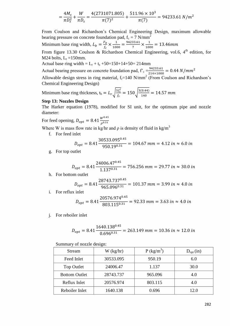
282
=4𝑀𝑠
𝜋𝐷𝑠2+
𝑊
𝜋𝐷𝑠=
4(2731071.805)
𝜋(7)2+
511.96 × 10³
𝜋(7)= 94233.61 𝑁/𝑚2
From Coulson and Richardson’s Chemical Engineering Design, maximum allowable
bearing pressure on concrete foundation pad, fc = 7 N/mm2
Minimum base ring width, 𝐿𝑏 =𝐹𝑏
𝑓𝑐×
1
1000=
94233.61
7×
1
1000= 13.46𝑚𝑚
From figure 13.30 Coulson & Richardson Chemical Engineering, vol.6, 4th
edition, for
M24 bolts, Lr =150mm.
Actual base ring width = Lr + ts +50=150+14+50= 214mm
Actual bearing pressure on concrete foundation pad, f’c =94233.61
214×1000= 0.44 𝑁/𝑚𝑚2
Allowable design stress in ring material, fr=140 N/mm2 (From Coulson and Richardson’s
Chemical Engineering Design)
Minimum base ring thickness, tb = 𝐿𝑟√3𝑓𝑐
′
𝑓𝑟= 150√
3(0.44)
140= 14.57 𝑚𝑚
Step 13: Nozzles Design
The Harker equation (1978), modified for SI unit, for the optimum pipe and nozzle
diameter:
For feed opening, 𝐷𝑜𝑝𝑡 = 8.41𝑊0.45
𝜌0.31
Where W is mass flow rate in kg/hr and ρ is density of fluid in kg/m3
f. For feed inlet
𝐷𝑜𝑝𝑡 = 8.4130533.0950.45
950.190.31= 104.67 𝑚𝑚 = 4.12 𝑖𝑛 ≈ 6.0 𝑖𝑛
g. For top outlet
𝐷𝑜𝑝𝑡 = 8.4124006.470.45
1.1370.31= 756.256 𝑚𝑚 = 29.77 𝑖𝑛 ≈ 30.0 𝑖𝑛
h. For bottom outlet
𝐷𝑜𝑝𝑡 = 8.4128743.7370.45
965.0960.31= 101.37 𝑚𝑚 = 3.99 𝑖𝑛 ≈ 4.0 𝑖𝑛
i. For reflux inlet
𝐷𝑜𝑝𝑡 = 8.4120576.9740.45
803.1150.31= 92.33 𝑚𝑚 = 3.63 𝑖𝑛 ≈ 4.0 𝑖𝑛
j. For reboiler inlet
𝐷𝑜𝑝𝑡 = 8.411640.1380.45
0.6960.31= 263.149 𝑚𝑚 = 10.36 𝑖𝑛 ≈ 12.0 𝑖𝑛
Summary of nozzle design:
Stream W (kg/hr) Ρ (kg/m3) Dopt (in)
Feed Inlet 30533.095 950.19 6.0
Top Outlet 24006.47 1.137 30.0
Bottom Outlet 28743.737 965.096 4.0
Reflux Inlet 20576.974 803.115 4.0
Reboiler Inlet 1640.138 0.696 12.0
283
Heat Transfer Equipment Design E-101-Feed Heater
The feed heater E-101 is used to heat up the mixture of methanol, water, dimethyl ether, hydrogen,
nitrogen, carbon dioxide and carbon monoxide from storage tank and also recycle stream at 11.00
bar from T=90OC to T= 100
OC, before this stream enters the synthesis reactor (R-101). The steam
used to heat up the mixture enters at T=250OC and leaves at T=150
OC at 11.10 bar.
Reference:
1. The calculation here follow the example paged 623-630 from Coulson and Richardson’s,
“Chemical Engineering, Volume 6”, 4th
edition.
2. FELDER, R. M. R., R. W. 2005. Elementary Principles of Chemical Processes, John
Wiley & Sons, Inc.
3. PERRY, R. H. A. G., DON W. 1984. Perry's Chemical Engineers' Handbook McGraw-
Hill.
4. SINNOTT, R. K. 2003. Chemical Engineering, Butterworth-Heineman
Design parameters:
Outside diameter (OD) and inside diameter (ID) for tubes Number of tubes
Number of tube passes and shell passes
Diameter of tube bundle, DB
Diameter of shell, DS
Baffle spacing, lb
Overall heat transfer coefficient
Tube side pressure drop, ΔPt
Shell side pressure drop, ΔPs
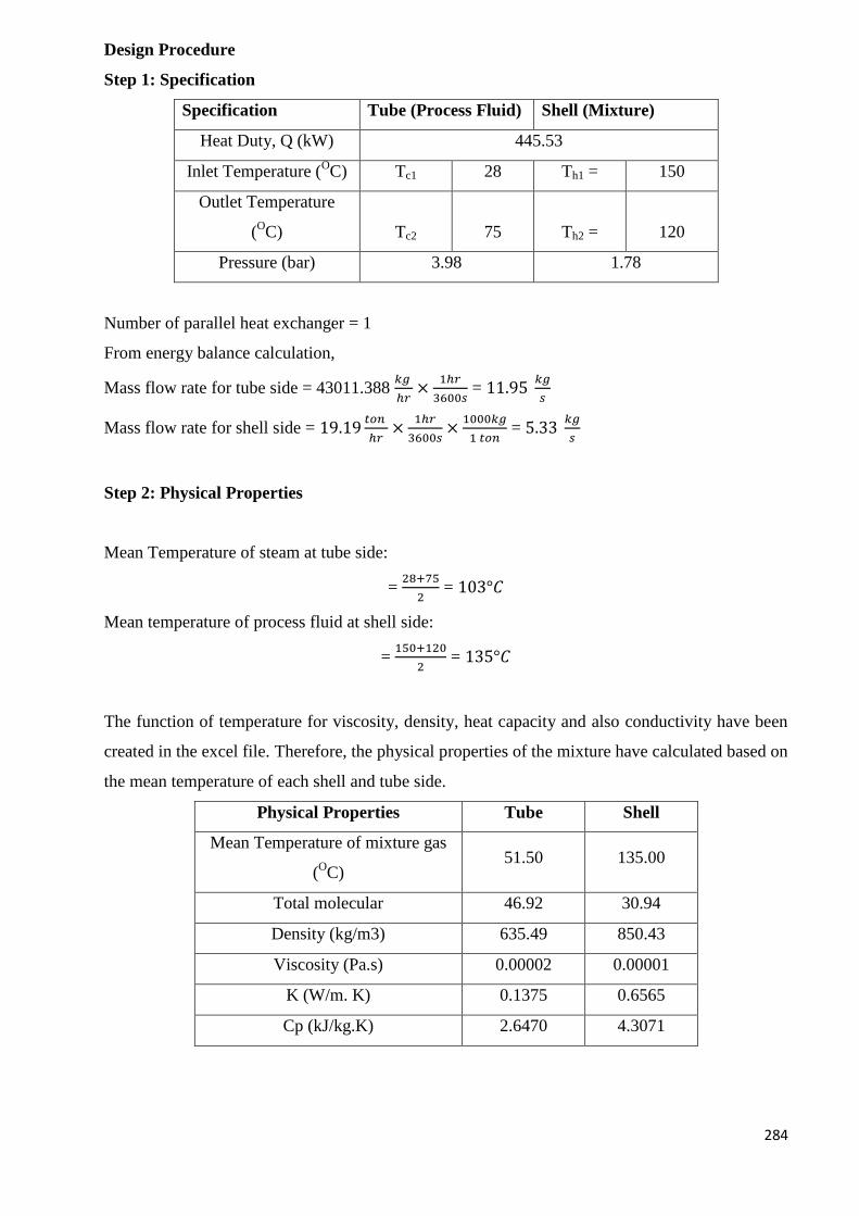
284
Design Procedure
Step 1: Specification
Specification Tube (Process Fluid) Shell (Mixture)
Heat Duty, Q (kW) 445.53
Inlet Temperature (OC) Tc1 28 Th1 = 150
Outlet Temperature
(OC) Tc2 75 Th2 = 120
Pressure (bar) 3.98 1.78
Number of parallel heat exchanger = 1
From energy balance calculation,
Mass flow rate for tube side = 43011.388 𝑘𝑔
ℎ𝑟×
1ℎ𝑟
3600𝑠 = 11.95
𝑘𝑔
𝑠
Mass flow rate for shell side = 19.19𝑡𝑜𝑛
ℎ𝑟×
1ℎ𝑟
3600𝑠×
1000𝑘𝑔
1 𝑡𝑜𝑛 = 5.33
𝑘𝑔
𝑠
Step 2: Physical Properties
Mean Temperature of steam at tube side:
= 28+75
2 = 103°𝐶
Mean temperature of process fluid at shell side:
= 150+120
2 = 135°𝐶
The function of temperature for viscosity, density, heat capacity and also conductivity have been
created in the excel file. Therefore, the physical properties of the mixture have calculated based on
the mean temperature of each shell and tube side.
Physical Properties Tube Shell
Mean Temperature of mixture gas
(OC)
51.50 135.00
Total molecular 46.92 30.94
Density (kg/m3) 635.49 850.43
Viscosity (Pa.s) 0.00002 0.00001
K (W/m. K) 0.1375 0.6565
Cp (kJ/kg.K) 2.6470 4.3071
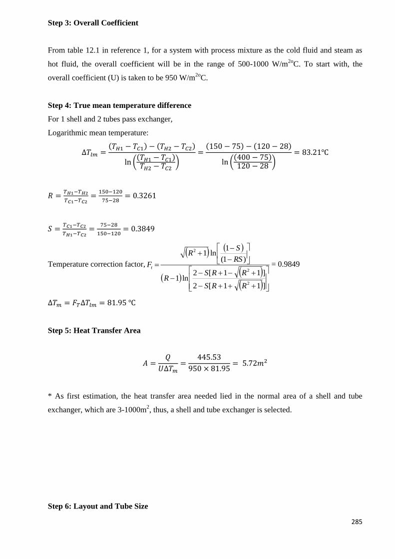
285
Step 3: Overall Coefficient
From table 12.1 in reference 1, for a system with process mixture as the cold fluid and steam as
hot fluid, the overall coefficient will be in the range of 500-1000 W/m2o
C. To start with, the
overall coefficient (U) is taken to be 950 W/m2o
C.
Step 4: True mean temperature difference
For 1 shell and 2 tubes pass exchanger,
Logarithmic mean temperature:
∆𝑇𝑙𝑚 =(𝑇𝐻1 − 𝑇𝐶1) − (𝑇𝐻2 − 𝑇𝐶2)
ln ((𝑇𝐻1 − 𝑇𝐶1)𝑇𝐻2 − 𝑇𝐶2
)=
(150 − 75) − (120 − 28)
ln ((400 − 75)120 − 28 )
= 83.21℃
𝑅 =𝑇𝐻1−𝑇𝐻2
𝑇𝐶1−𝑇𝐶2=
150−120
75−28= 0.3261
𝑆 =𝑇𝐶1−𝑇𝐶2
𝑇𝐻1−𝑇𝐶2=
75−28
150−120= 0.3849
Temperature correction factor,
]11[2
]11[2ln1
)1(
1ln1
2
2
2
RRS
RRSR
RS
SR
Ft= 0.9849
∆𝑇𝑚 = 𝐹𝑇∆𝑇𝑙𝑚 = 81.95 ℃
Step 5: Heat Transfer Area
𝐴 =𝑄
𝑈∆𝑇𝑚=
445.53
950 × 81.95= 5.72𝑚2
* As first estimation, the heat transfer area needed lied in the normal area of a shell and tube
exchanger, which are 3-1000m2, thus, a shell and tube exchanger is selected.
Step 6: Layout and Tube Size
286
In order to obtain higher efficiency and ease the cleaning process, a split-ring floating-
head exchanger is used.
The material of construction for heat exchangers is stainless steel 316. Allocating the fluid
with the highest flow rate to the tube side will normally give the most economical design.
Besides, in reference 1, it is said that the fluid with the lowest allowable pressure drop
should be allocated to the tube side.
The preferred tube diameter for most duties is from 5/8 to 2 in., as they will give more compact
and therefore cheaper exchangers.
Outer diameter, DO = 19.05 mm = 0.019m
Internal diameter, DI = 15.8 mm = 0.0158m
Length of tube, LT = 1.83 long, which is the most popular size.
As there is no presence of heavily fouling fluids in this system, triangular pattern of tube
arrangements can be applied. The triangular patterns can give a higher heat transfer rates.
The recommended tube pitch (distance between tube canters) is 1.25 × 𝐷𝑂 = 0.0238𝑚 is
employed.
Step 7: Number of Tubes
Area of one tube (neglecting thickness of tube sheets)
= 𝜋 × 𝐷𝑂 × 𝐿𝑇 = 𝜋 × 0.019 𝑚 × 1.83 𝑚 = 0.11 𝑚2
𝑁𝑢𝑚𝑏𝑒𝑟 𝑜𝑓𝑡𝑢𝑏𝑒𝑠 = 5.72 𝑚2
0.11 𝑚2= 𝟓𝟐 = 𝟐𝟔
Earlier before, a heat exchanger with 1 shell passes and 2 tubes passes is selected. So, for 2 passes,
tubes per pass = 1505 tubes
𝑇𝑢𝑏𝑒 𝑐𝑟𝑜𝑠𝑠 𝑠𝑒𝑐𝑡𝑖𝑜𝑛𝑎𝑙 𝑎𝑟𝑒𝑎 = 𝜋 × (𝐷𝐼)
2
4=
𝜋 × (0.0158)2
4= 1.96 × 10⁻⁴𝑚2
𝐴𝑟𝑒𝑎 𝑝𝑒𝑟 𝑝𝑎𝑠𝑠 = 26 × 1.96 × 10−4𝑚2 = 0.0051 𝑚2
𝑉𝑜𝑙𝑢𝑚𝑒𝑡𝑟𝑖𝑐 𝑓𝑙𝑜𝑤 𝑟𝑎𝑡𝑒 = 11.95 𝑘𝑔/𝑠
635.50 𝑘𝑔/𝑚3= 0.019 𝑚3/𝑠
𝑇𝑢𝑏𝑒 𝑠𝑖𝑑𝑒 𝑣𝑒𝑙𝑜𝑐𝑖𝑡𝑦, 𝑢𝑡 = 0.019 𝑚3/𝑠
0.0051 𝑚2= 3.67 𝑚/𝑠
287
Step 8: Bundle and Shell Diameter
From Table 12.4 (Coulson & Richardson’s Chemical Engineering), for 2 tube passes,
K1 = 0.249 n1 =2.207
𝐵𝑢𝑛𝑑𝑙𝑒 𝑑𝑖𝑎𝑚𝑒𝑡𝑒𝑟, 𝐷𝑏(𝑚𝑚) = 𝑑𝑜 (𝑁𝑡
𝐾1)
1𝑛1
⁄
= 0.01905 (52
0.249)
12.207⁄
= 0.21 𝑚
where Nt= number of tubes
do= tube outside diameter, mm
Referring to Figure 12.10 (Coulson & Richardson’s Chemical Engineering), when Db= 2.27 m,
the shell clearance is 80mm = 0.08m.
Hence, the shell inside diameter will be:
𝐷𝑠 = 0.21 𝑚 + 0.05 𝑚 = 𝟎. 𝟐𝟔 𝒎
TEMA standard Ds is max 1.520 m. So, Ds is within the allow range.
Step 9: Tube-side Heat Transfer Coefficient
𝑇𝑢𝑏𝑒 𝑠𝑖𝑑𝑒 𝑚𝑎𝑠𝑠 𝑣𝑒𝑙𝑜𝑐𝑖𝑡𝑦, 𝐺𝑡 =𝑊𝑡
𝐴𝑡=
11.95𝑘𝑔𝑠
0.0051𝑚2= 𝟐𝟑𝟑𝟐. 𝟒𝟑 𝒌𝒈/𝒎𝟐𝒔
𝑅𝑒𝑦𝑛𝑜𝑙𝑑𝑠 𝑛𝑢𝑚𝑏𝑒𝑟, 𝑅𝑒 =𝐺𝑡𝑑𝑖
𝜇𝑐=
𝟐𝟑𝟑𝟐. 𝟒𝟐𝑘𝑔𝑚2𝑠
× 0.0158𝑚
0.002 𝑘𝑔𝑚. 𝑠
= 163847.77
𝑃𝑟𝑎𝑛𝑑𝑡𝑙 𝑛𝑢𝑚𝑏𝑒𝑟, 𝑃𝑟 =𝐶𝑝,𝑐𝜇𝑐
𝑘𝑐=
2.65𝑘𝐽
𝑘𝑔.𝐾×1000×0.002
𝑘𝑔
𝑚.𝑠
0.1375𝑊
𝑚.𝐾
= 4.33
𝐿
𝑑𝑜=
1.83 𝑚
0.01905 𝑚𝑚= 𝟗𝟔. 𝟎𝟔
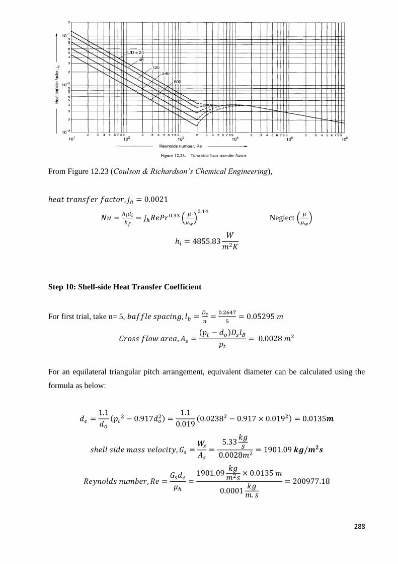
288
From Figure 12.23 (Coulson & Richardson’s Chemical Engineering),
ℎ𝑒𝑎𝑡 𝑡𝑟𝑎𝑛𝑠𝑓𝑒𝑟 𝑓𝑎𝑐𝑡𝑜𝑟, 𝑗ℎ = 0.0021
𝑁𝑢 =ℎ𝑖𝑑𝑖
𝑘𝑓= 𝑗ℎ𝑅𝑒𝑃𝑟0.33 (
𝜇
𝜇𝑤)0.14
Neglect (𝜇
𝜇𝑤)
ℎ𝑖 = 4855.83𝑊
𝑚2𝐾
Step 10: Shell-side Heat Transfer Coefficient
For first trial, take n= 5, 𝑏𝑎𝑓𝑓𝑙𝑒 𝑠𝑝𝑎𝑐𝑖𝑛𝑔, 𝑙𝑏 =𝐷𝑠
𝑛=
0.2647
5= 0.05295 𝑚
𝐶𝑟𝑜𝑠𝑠 𝑓𝑙𝑜𝑤 𝑎𝑟𝑒𝑎, 𝐴𝑠 =(𝑝𝑡 − 𝑑𝑜)𝐷𝑠𝑙𝐵
𝑝𝑡= 0.0028 𝑚2
For an equilateral triangular pitch arrangement, equivalent diameter can be calculated using the
formula as below:
𝑑𝑒 =1.1
𝑑𝑜
(𝑝𝑡2 − 0.917𝑑𝑜
2) =1.1
0.019(0.02382 − 0.917 × 0.0192) = 0.0135𝒎
𝑠ℎ𝑒𝑙𝑙 𝑠𝑖𝑑𝑒 𝑚𝑎𝑠𝑠 𝑣𝑒𝑙𝑜𝑐𝑖𝑡𝑦, 𝐺𝑠 =𝑊𝑠
𝐴𝑠=
5.33𝑘𝑔𝑠
0.0028𝑚2= 1901.09 𝒌𝒈/𝒎𝟐𝒔
𝑅𝑒𝑦𝑛𝑜𝑙𝑑𝑠 𝑛𝑢𝑚𝑏𝑒𝑟, 𝑅𝑒 =𝐺𝑠𝑑𝑒
𝜇ℎ=
1901.09𝑘𝑔𝑚2𝑠
× 0.0135 𝑚
0.0001𝑘𝑔𝑚. 𝑠
= 200977.18
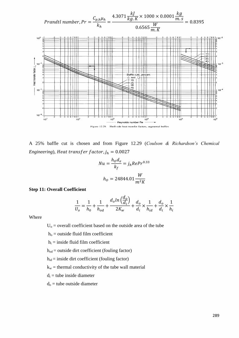
289
𝑃𝑟𝑎𝑛𝑑𝑡𝑙 𝑛𝑢𝑚𝑏𝑒𝑟, 𝑃𝑟 =𝐶𝑝,ℎ𝜇ℎ
𝑘ℎ=
4.3071𝑘𝐽
𝑘𝑔. 𝐾× 1000 × 0.0001
𝑘𝑔𝑚. 𝑠
0.6565𝑊
𝑚.𝐾
= 0.8395
A 25% baffle cut is chosen and from Figure 12.29 (Coulson & Richardson’s Chemical
Engineering), 𝐻𝑒𝑎𝑡 𝑡𝑟𝑎𝑛𝑠𝑓𝑒𝑟 𝑓𝑎𝑐𝑡𝑜𝑟, 𝑗ℎ = 0.0027
𝑁𝑢 =ℎ𝑂𝑑𝑒
𝑘𝑓= 𝑗ℎ𝑅𝑒𝑃𝑟0.33
ℎ𝑂 = 24844.01𝑊
𝑚2𝐾
Step 11: Overall Coefficient
1
𝑈𝑜=
1
ℎ0+
1
ℎ𝑜𝑑+
𝑑𝑜𝑙𝑛 (𝑑𝑜
𝑑𝑖)
2𝐾𝑤+
𝑑𝑜
𝑑𝑖×
1
ℎ𝑖𝑑+
𝑑𝑜
𝑑𝑖×
1
ℎ𝑖
Where
Uo = overall coefficient based on the outside area of the tube
ho = outside fluid film coefficient
hi = inside fluid film coefficient
hod = outside dirt coefficient (fouling factor)
hid = inside dirt coefficient (fouling factor)
kw = thermal conductivity of the tube wall material
di = tube inside diameter
do = tube outside diameter
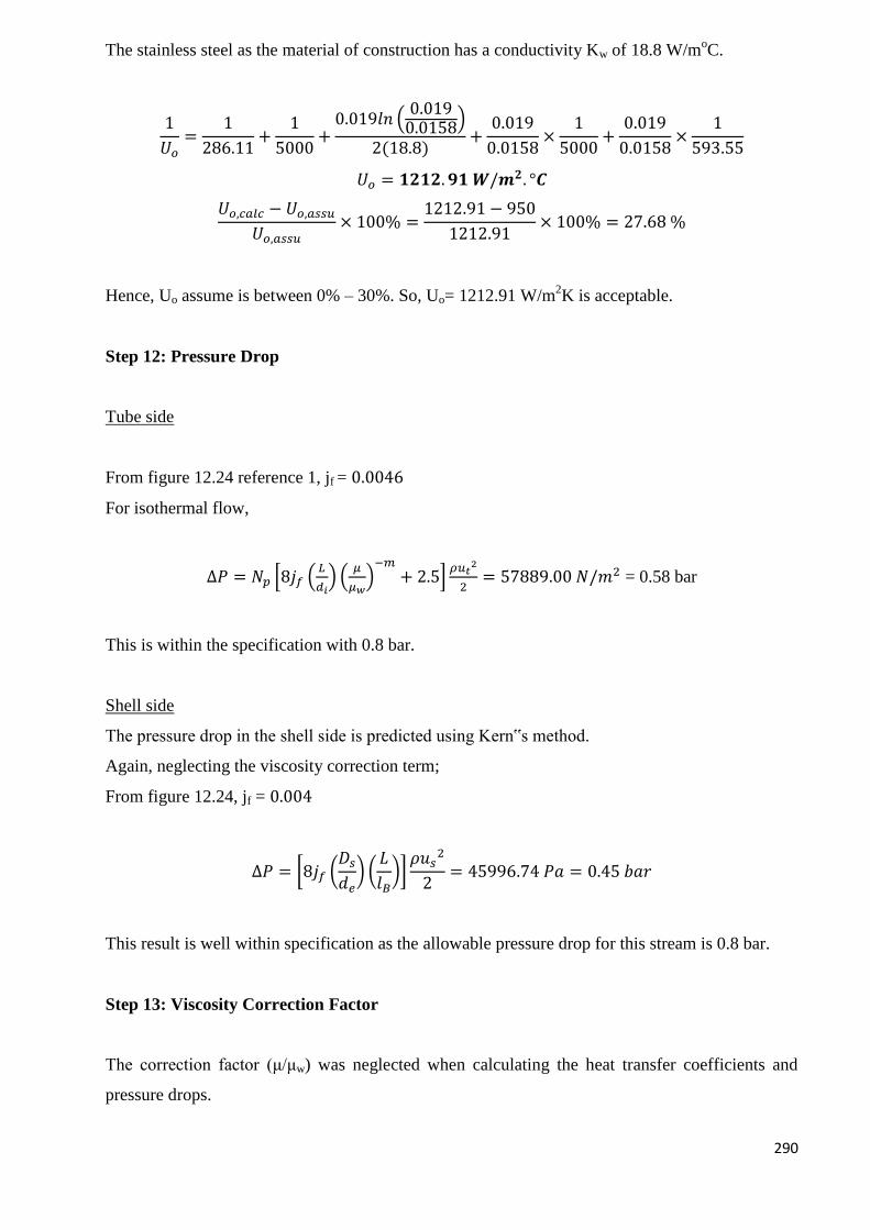
290
The stainless steel as the material of construction has a conductivity Kw of 18.8 W/moC.
1
𝑈𝑜=
1
286.11+
1
5000+
0.019𝑙𝑛 (0.0190.0158
)
2(18.8)+
0.019
0.0158×
1
5000+
0.019
0.0158×
1
593.55
𝑈𝑜 = 𝟏𝟐𝟏𝟐. 𝟗𝟏 𝑾/𝒎𝟐. °𝑪
𝑈𝑜,𝑐𝑎𝑙𝑐 − 𝑈𝑜,𝑎𝑠𝑠𝑢
𝑈𝑜,𝑎𝑠𝑠𝑢× 100% =
1212.91 − 950
1212.91× 100% = 27.68 %
Hence, Uo assume is between 0% – 30%. So, Uo= 1212.91 W/m2K is acceptable.
Step 12: Pressure Drop
Tube side
From figure 12.24 reference 1, jf = 0.0046
For isothermal flow,
∆𝑃 = 𝑁𝑝 [8𝑗𝑓 (𝐿
𝑑𝑖) (
𝜇
𝜇𝑤)−𝑚
+ 2.5]𝜌𝑢𝑡
2
2= 57889.00 𝑁/𝑚2 = 0.58 bar
This is within the specification with 0.8 bar.
Shell side
The pressure drop in the shell side is predicted using Kern‟s method.
Again, neglecting the viscosity correction term;
From figure 12.24, jf = 0.004
∆𝑃 = [8𝑗𝑓 (𝐷𝑠
𝑑𝑒) (
𝐿
𝑙𝐵)]
𝜌𝑢𝑠2
2= 45996.74 𝑃𝑎 = 0.45 𝑏𝑎𝑟
This result is well within specification as the allowable pressure drop for this stream is 0.8 bar.
Step 13: Viscosity Correction Factor
The correction factor (μ/μw) was neglected when calculating the heat transfer coefficients and
pressure drops.
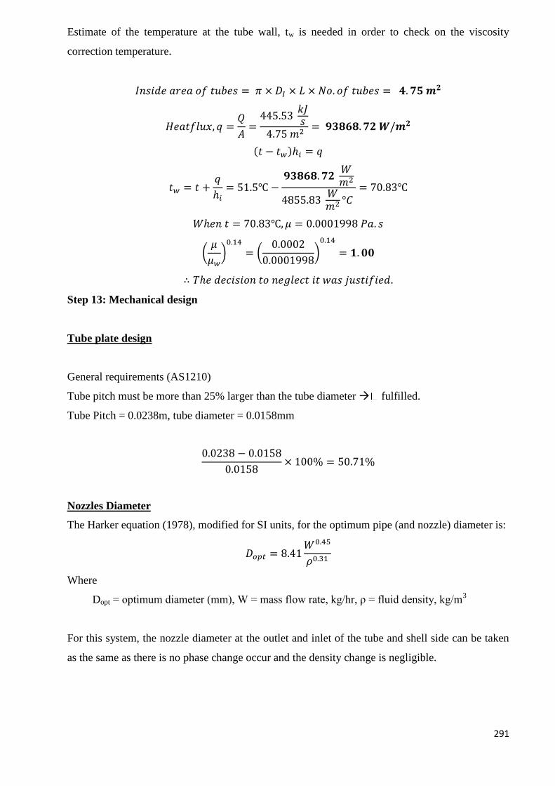
291
Estimate of the temperature at the tube wall, tw is needed in order to check on the viscosity
correction temperature.
𝐼𝑛𝑠𝑖𝑑𝑒 𝑎𝑟𝑒𝑎 𝑜𝑓 𝑡𝑢𝑏𝑒𝑠 = 𝜋 × 𝐷𝐼 × 𝐿 × 𝑁𝑜. 𝑜𝑓 𝑡𝑢𝑏𝑒𝑠 = 𝟒. 𝟕𝟓 𝒎𝟐
𝐻𝑒𝑎𝑡𝑓𝑙𝑢𝑥, 𝑞 =𝑄
𝐴=
445.53 𝑘𝐽𝑠
4.75 𝑚2= 𝟗𝟑𝟖𝟔𝟖. 𝟕𝟐 𝑾/𝒎𝟐
(𝑡 − 𝑡𝑤)ℎ𝑖 = 𝑞
𝑡𝑤 = 𝑡 +𝑞
ℎ𝑖= 51.5℃ −
𝟗𝟑𝟖𝟔𝟖. 𝟕𝟐 𝑊𝑚2
4855.83 𝑊𝑚2 °𝐶
= 70.83℃
𝑊ℎ𝑒𝑛 𝑡 = 70.83℃, 𝜇 = 0.0001998 𝑃𝑎. 𝑠
(𝜇
𝜇𝑤)0.14
= (0.0002
0.0001998)0.14
= 𝟏. 𝟎𝟎
∴ 𝑇ℎ𝑒 𝑑𝑒𝑐𝑖𝑠𝑖𝑜𝑛 𝑡𝑜 𝑛𝑒𝑔𝑙𝑒𝑐𝑡 𝑖𝑡 𝑤𝑎𝑠 𝑗𝑢𝑠𝑡𝑖𝑓𝑖𝑒𝑑.
Step 13: Mechanical design
Tube plate design
General requirements (AS1210)
Tube pitch must be more than 25% larger than the tube diameter fulfilled.
Tube Pitch = 0.0238m, tube diameter = 0.0158mm
0.0238 − 0.0158
0.0158× 100% = 50.71%
Nozzles Diameter
The Harker equation (1978), modified for SI units, for the optimum pipe (and nozzle) diameter is:
𝐷𝑜𝑝𝑡 = 8.41𝑊0.45
𝜌0.31
Where
Dopt = optimum diameter (mm), W = mass flow rate, kg/hr, ρ = fluid density, kg/m3
For this system, the nozzle diameter at the outlet and inlet of the tube and shell side can be taken
as the same as there is no phase change occur and the density change is negligible.
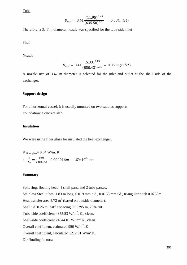
292
Tube
𝐷𝑜𝑝𝑡 = 8.41(11.95)0.45
(635.50)0.31 = 0.08(𝑖𝑛𝑙𝑒𝑡)
Therefore, a 3.47 m diameter nozzle was specified for the tube-side inlet
Shell
Nozzle
𝐷𝑜𝑝𝑡 = 8.41(5.33)0.45
(850.43)0.31 = 0.05 𝑚 (𝑖𝑛𝑙𝑒𝑡)
A nozzle size of 3.47 m diameter is selected for the inlet and outlet at the shell side of the
exchanger.
Support design
For a horizontal vessel, it is usually mounted on two saddles supports.
Foundation: Concrete slab
Insulation
We were using fiber glass for insulated the heat exchanger.
K fiber glass= 0.04 W/m. K
r = 𝐾
ℎ𝑜=
0.04
248446.1 =0.000016𝑚 = 1.69x10
-9 mm
Summary
Split ring, floating head, 1 shell pass, and 2 tube passes.
Stainless Steel tubes, 1.83 m long, 0.019 mm o.d., 0.0158 mm i.d., triangular pitch 0.0238m.
Heat transfer area 5.72 m2 (based on outside diameter).
Shell i.d. 0.26 m, baffle spacing 0.05295 m, 25% cut.
Tube-side coefficient 4855.83 W/m2. K., clean.
Shell-side coefficient 24844.01 W/ m2.K., clean.
Overall coefficient, estimated 950 W/m2. K.
Overall coefficient, calculated 1212.91 W/m2.K.
Dirt/fouling factors:
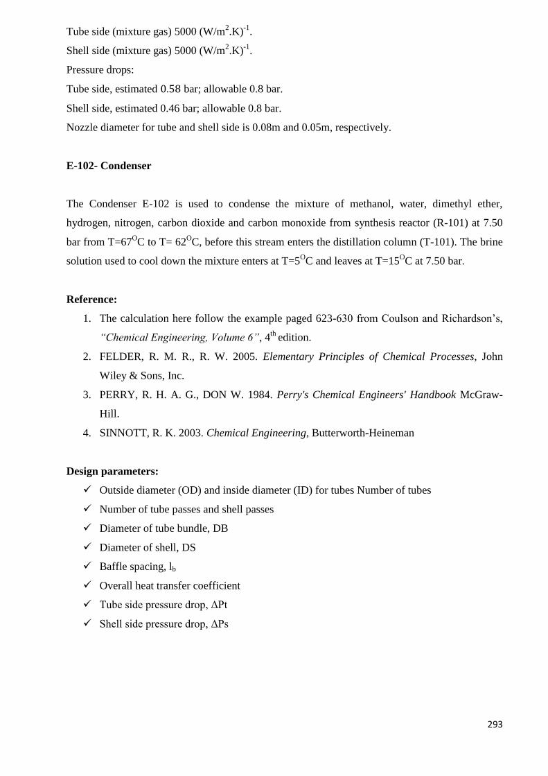
293
Tube side (mixture gas) 5000 (W/m2.K)
-1.
Shell side (mixture gas) 5000 (W/m2.K)
-1.
Pressure drops:
Tube side, estimated 0.58 bar; allowable 0.8 bar.
Shell side, estimated 0.46 bar; allowable 0.8 bar.
Nozzle diameter for tube and shell side is 0.08m and 0.05m, respectively.
E-102- Condenser
The Condenser E-102 is used to condense the mixture of methanol, water, dimethyl ether,
hydrogen, nitrogen, carbon dioxide and carbon monoxide from synthesis reactor (R-101) at 7.50
bar from T=67OC to T= 62
OC, before this stream enters the distillation column (T-101). The brine
solution used to cool down the mixture enters at T=5OC and leaves at T=15
OC at 7.50 bar.
Reference:
1. The calculation here follow the example paged 623-630 from Coulson and Richardson’s,
“Chemical Engineering, Volume 6”, 4th
edition.
2. FELDER, R. M. R., R. W. 2005. Elementary Principles of Chemical Processes, John
Wiley & Sons, Inc.
3. PERRY, R. H. A. G., DON W. 1984. Perry's Chemical Engineers' Handbook McGraw-
Hill.
4. SINNOTT, R. K. 2003. Chemical Engineering, Butterworth-Heineman
Design parameters:
Outside diameter (OD) and inside diameter (ID) for tubes Number of tubes
Number of tube passes and shell passes
Diameter of tube bundle, DB
Diameter of shell, DS
Baffle spacing, lb
Overall heat transfer coefficient
Tube side pressure drop, ΔPt
Shell side pressure drop, ΔPs
294
Design Procedure
Step 1: Specification
Specification Tube (chilled Water) Shell (Process Fluid)
Heat Duty, Q (kW) 10562.63
Inlet Temperature (OC) TC2 = 5 TH1 = 67
Outlet Temperature
(OC) TC1 = 15 TH2 = 62
Pressure (bar) 7.50 7.50
Number of parallel heat exchanger = 1
From energy balance calculation,
Mass flow rate for tube side = 28280.66 𝑘𝑔
ℎ𝑟×
1ℎ𝑟
3600𝑠 = 7.86
𝑘𝑔
𝑠
Mass flow rate for shell side = 454.85 𝑡𝑜𝑛
ℎ𝑟×
1ℎ𝑟
3600𝑠×
1000𝑘𝑔
1 𝑡𝑜𝑛 = 126.35
𝑘𝑔
𝑠
Step 2: Physical Properties
Mean Temperature of brine solution at tube side:
= 5+15
2 = 10°𝐶
Mean temperature of process fluid at shell side:
= 67+62
2 = 64.5°𝐶
The function of temperature for viscosity, density, heat capacity and also conductivity have been
created in the excel file. Therefore, the physical properties of the mixture have calculated based on
the mean temperature of each shell and tube side.
Physical Properties Tube Shell
Mean Temperature (OC) 10 64.5
Total molecular 18.72 44.67
Density (kg/m3) 1198.8 664.78
Viscosity (Pa.s) 0.0013 0.0002
K (W/m.K) 0.6235 0.1497
Cp kJ/kg.K 4.1787 2.7123
295
Step 3: Overall Coefficient
From table 12.1 in reference 1, for a system with organic solvent as the hot fluid and water as cold
fluid, the overall coefficient will be in the range of 250-750 W/m2o
C. To start with, the overall
coefficient (U) is taken to be 390 W/m2o
C.
Step 4: True mean temperature difference
For 1 shell and 2 tubes pass exchanger,
Logarithmic mean temperature:
∆𝑇𝑙𝑚 =(𝑇𝐻1 − 𝑇𝐶1) − (𝑇𝐻2 − 𝑇𝐶2)
ln ((𝑇𝐻1 − 𝑇𝐶1)𝑇𝐻2 − 𝑇𝐶2
)=
(67 − 15) − (62 − 5)
ln (67 − 1562 − 5
)= 54.46℃
𝑅 =𝑇𝐻1 − 𝑇𝐻2
𝑇𝐶1 − 𝑇𝐶2=
67 − 15
15 − 5= 5.20
𝑆 =𝑇𝐶1 − 𝑇𝐶2
𝑇𝐻1 − 𝑇𝐶2=
15 − 5
67 − 5= 0.1613
Temperature correction factor,
]11[2
]11[2ln1
)1(
1ln1
2
2
2
RRS
RRSR
RS
SR
Ft = 0.8177
∆𝑇𝑚 = 𝐹𝑇∆𝑇𝑙𝑚 = 44.53℃
Step 5: Heat Transfer Area
𝐴 =𝑄
𝑈∆𝑇𝑚=
10562.6278
500×44.5323= 474.38𝑚24
* As first estimation, the heat transfer area needed lied in the normal area of a shell and tube
exchanger, which are 3-1000m2, thus, a shell and tube exchanger is selected.
Step 6: Layout and Tube Size
In order to obtain higher efficiency and ease the cleaning process, a split-ring floating-
head exchanger is used.
The material of construction for heat exchangers is stainless steel 316. A higher flow rate
stream should be allocated to the tube side as it will normally give the most economical
design. Besides, in reference 1, it is said that the fluid with the lowest allowable pressure
drop should be allocated to the tube side.
296
The preferred tube diameter for most duties is from 5/8 to 2 in., as they will give more compact
and therefore cheaper exchangers.
Outer diameter, DO = 19.05 mm = 0.019m
Internal diameter, DI = 15.8 mm = 0.0158m
Length of tube, LT = 5 m long, which is the most popular size.
As there is no presence of heavily fouling fluids in this system, triangular pattern of tube
arrangements can be applied. The triangular patterns can give a higher heat transfer rates.
The recommended tube pitch (distance between tube canters) is 1.25 × 𝐷𝑂 = 0.0238𝑚 is
employed.
Step 7: Number of Tubes
Area of one tube (neglecting thickness of tube sheets)
= 𝜋 × 𝐷𝑂 × 𝐿𝑇 = 𝜋 × 0.019 𝑚 × 7.32 𝑚 = 0.30𝑚2
𝑁𝑢𝑚𝑏𝑒𝑟 𝑜𝑓𝑡𝑢𝑏𝑒𝑠 = 474.38𝑚2
0.30𝑚2= 𝟏𝟖𝟖𝟏. 𝟕 = 𝟏𝟓𝟖𝟓
Earlier before, a heat exchanger with 1 shell passes and 2 tubes passes or multiple of four is
selected. So, for 4 passes, tubes per pass = 396
𝑇𝑢𝑏𝑒 𝑐𝑟𝑜𝑠𝑠 𝑠𝑒𝑐𝑡𝑖𝑜𝑛𝑎𝑙 𝑎𝑟𝑒𝑎 = 𝜋 × (𝐷𝐼)
2
4=
𝜋 × (0.015)2
4= 1.961 × 10⁻⁴𝑚2
𝐴𝑟𝑒𝑎 𝑝𝑒𝑟 𝑝𝑎𝑠𝑠 = 396 × 1.961 × 10−4𝑚2 = 0.077 𝑚2
At mean temperature, the density of tube side is 1198.80 kg/m3
𝑉𝑜𝑙𝑢𝑚𝑒𝑡𝑟𝑖𝑐 𝑓𝑙𝑜𝑤 𝑟𝑎𝑡𝑒 = 126.35 𝑘𝑔/𝑠
1198.80 𝑘𝑔/𝑚3= 0.1054𝑚3/𝑠
𝑇𝑢𝑏𝑒 𝑠𝑖𝑑𝑒 𝑣𝑒𝑙𝑜𝑐𝑖𝑡𝑦, 𝑢𝑡 = 0.1054𝑚3/𝑠
0.0777 𝑚2= 0.437 𝑚/𝑠
Step 8: Bundle and Shell Diameter
From Table 12.4 (Coulson & Richardson’s Chemical Engineering), for 2 tube passes,
K1 = 0.249 n1 =2.207
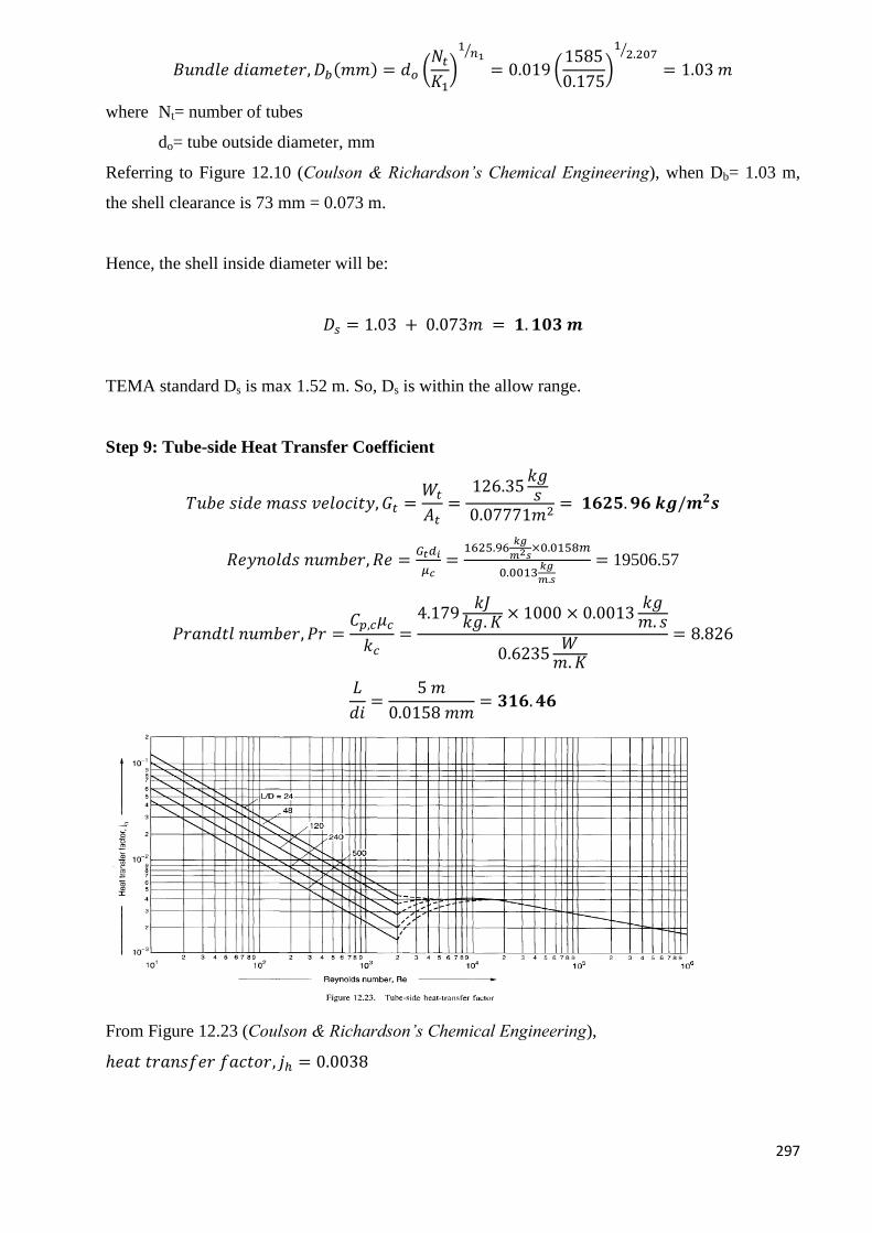
297
𝐵𝑢𝑛𝑑𝑙𝑒 𝑑𝑖𝑎𝑚𝑒𝑡𝑒𝑟, 𝐷𝑏(𝑚𝑚) = 𝑑𝑜 (𝑁𝑡
𝐾1)
1𝑛1
⁄
= 0.019 (1585
0.175)
12.207⁄
= 1.03 𝑚
where Nt= number of tubes
do= tube outside diameter, mm
Referring to Figure 12.10 (Coulson & Richardson’s Chemical Engineering), when Db= 1.03 m,
the shell clearance is 73 mm = 0.073 m.
Hence, the shell inside diameter will be:
𝐷𝑠 = 1.03 + 0.073𝑚 = 𝟏. 𝟏𝟎𝟑 𝒎
TEMA standard Ds is max 1.52 m. So, Ds is within the allow range.
Step 9: Tube-side Heat Transfer Coefficient
𝑇𝑢𝑏𝑒 𝑠𝑖𝑑𝑒 𝑚𝑎𝑠𝑠 𝑣𝑒𝑙𝑜𝑐𝑖𝑡𝑦, 𝐺𝑡 =𝑊𝑡
𝐴𝑡=
126.35𝑘𝑔𝑠
0.07771𝑚2= 𝟏𝟔𝟐𝟓. 𝟗𝟔 𝒌𝒈/𝒎𝟐𝒔
𝑅𝑒𝑦𝑛𝑜𝑙𝑑𝑠 𝑛𝑢𝑚𝑏𝑒𝑟, 𝑅𝑒 =𝐺𝑡𝑑𝑖
𝜇𝑐=
1625.96𝑘𝑔
𝑚2𝑠×0.0158𝑚
0.0013𝑘𝑔
𝑚.𝑠
= 19506.57
𝑃𝑟𝑎𝑛𝑑𝑡𝑙 𝑛𝑢𝑚𝑏𝑒𝑟, 𝑃𝑟 =𝐶𝑝,𝑐𝜇𝑐
𝑘𝑐=
4.179𝑘𝐽
𝑘𝑔. 𝐾× 1000 × 0.0013
𝑘𝑔𝑚. 𝑠
0.6235𝑊
𝑚.𝐾
= 8.826
𝐿
𝑑𝑖=
5 𝑚
0.0158 𝑚𝑚= 𝟑𝟏𝟔. 𝟒𝟔
From Figure 12.23 (Coulson & Richardson’s Chemical Engineering),
ℎ𝑒𝑎𝑡 𝑡𝑟𝑎𝑛𝑠𝑓𝑒𝑟 𝑓𝑎𝑐𝑡𝑜𝑟, 𝑗ℎ = 0.0038
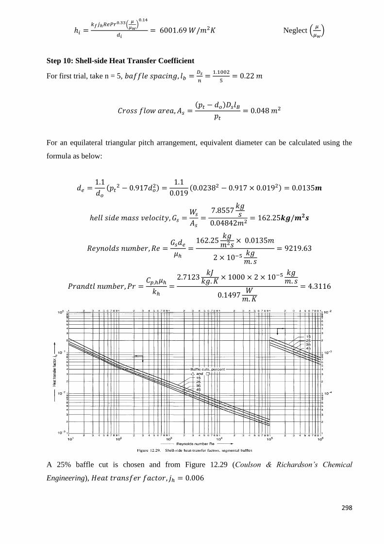
298
ℎ𝑖 =𝑘𝑓𝑗ℎ𝑅𝑒𝑃𝑟0.33(
𝜇
𝜇𝑤)0.14
𝑑𝑖= 6001.69 𝑊/𝑚2𝐾 Neglect (
𝜇
𝜇𝑤)
Step 10: Shell-side Heat Transfer Coefficient
For first trial, take n = 5, 𝑏𝑎𝑓𝑓𝑙𝑒 𝑠𝑝𝑎𝑐𝑖𝑛𝑔, 𝑙𝑏 =𝐷𝑠
𝑛=
1.1002
5= 0.22 𝑚
𝐶𝑟𝑜𝑠𝑠 𝑓𝑙𝑜𝑤 𝑎𝑟𝑒𝑎, 𝐴𝑠 =(𝑝𝑡 − 𝑑𝑜)𝐷𝑠𝑙𝐵
𝑝𝑡= 0.048 𝑚2
For an equilateral triangular pitch arrangement, equivalent diameter can be calculated using the
formula as below:
𝑑𝑒 =1.1
𝑑𝑜
(𝑝𝑡2 − 0.917𝑑𝑜
2) =1.1
0.019(0.02382 − 0.917 × 0.0192) = 0.0135𝒎
ℎ𝑒𝑙𝑙 𝑠𝑖𝑑𝑒 𝑚𝑎𝑠𝑠 𝑣𝑒𝑙𝑜𝑐𝑖𝑡𝑦, 𝐺𝑠 =𝑊𝑠
𝐴𝑠=
7.8557𝑘𝑔𝑠
0.04842𝑚2= 162.25𝒌𝒈/𝒎𝟐𝒔
𝑅𝑒𝑦𝑛𝑜𝑙𝑑𝑠 𝑛𝑢𝑚𝑏𝑒𝑟, 𝑅𝑒 =𝐺𝑠𝑑𝑒
𝜇ℎ=
162.25𝑘𝑔𝑚2𝑠
× 0.0135𝑚
2 × 10⁻⁵ 𝑘𝑔𝑚. 𝑠
= 9219.63
𝑃𝑟𝑎𝑛𝑑𝑡𝑙 𝑛𝑢𝑚𝑏𝑒𝑟, 𝑃𝑟 =𝐶𝑝,ℎ𝜇ℎ
𝑘ℎ=
2.7123𝑘𝐽
𝑘𝑔. 𝐾× 1000 × 2 × 10−5 𝑘𝑔
𝑚. 𝑠
0.1497𝑊
𝑚.𝐾
= 4.3116
A 25% baffle cut is chosen and from Figure 12.29 (Coulson & Richardson’s Chemical
Engineering), 𝐻𝑒𝑎𝑡 𝑡𝑟𝑎𝑛𝑠𝑓𝑒𝑟 𝑓𝑎𝑐𝑡𝑜𝑟, 𝑗ℎ = 0.006
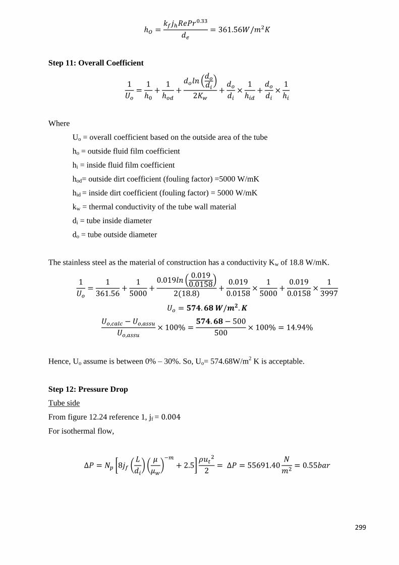
299
ℎ𝑂 =𝑘𝑓𝑗ℎ𝑅𝑒𝑃𝑟0.33
𝑑𝑒= 361.56𝑊/𝑚2𝐾
Step 11: Overall Coefficient
1
𝑈𝑜=
1
ℎ0+
1
ℎ𝑜𝑑+
𝑑𝑜𝑙𝑛 (𝑑𝑜
𝑑𝑖)
2𝐾𝑤+
𝑑𝑜
𝑑𝑖×
1
ℎ𝑖𝑑+
𝑑𝑜
𝑑𝑖×
1
ℎ𝑖
Where
Uo = overall coefficient based on the outside area of the tube
ho = outside fluid film coefficient
hi = inside fluid film coefficient
hod= outside dirt coefficient (fouling factor) =5000 W/mK
hid = inside dirt coefficient (fouling factor) = 5000 W/mK
kw = thermal conductivity of the tube wall material
di = tube inside diameter
do = tube outside diameter
The stainless steel as the material of construction has a conductivity Kw of 18.8 W/mK.
1
𝑈𝑜=
1
361.56+
1
5000+
0.019𝑙𝑛 (0.0190.0158
)
2(18.8)+
0.019
0.0158×
1
5000+
0.019
0.0158×
1
3997
𝑈𝑜 = 𝟓𝟕𝟒. 𝟔𝟖 𝑾/𝒎𝟐. 𝑲
𝑈𝑜,𝑐𝑎𝑙𝑐 − 𝑈𝑜,𝑎𝑠𝑠𝑢
𝑈𝑜,𝑎𝑠𝑠𝑢× 100% =
𝟓𝟕𝟒. 𝟔𝟖 − 500
500× 100% = 14.94%
Hence, Uo assume is between 0% – 30%. So, Uo= 574.68W/m2 K is acceptable.
Step 12: Pressure Drop
Tube side
From figure 12.24 reference 1, jf = 0.004
For isothermal flow,
∆𝑃 = 𝑁𝑝 [8𝑗𝑓 (𝐿
𝑑𝑖) (
𝜇
𝜇𝑤)−𝑚
+ 2.5]𝜌𝑢𝑡
2
2= ∆𝑃 = 55691.40
𝑁
𝑚2= 0.55𝑏𝑎𝑟
300
* 2.5 is the recommended value for the velocity heads per pass. Neglecting the viscosity
correction term
This is within the specification with 0.8 bar.
Shell side
The pressure drop in the shell side is predicted using Kern‟s method.
Again, neglecting the viscosity correction term;
From figure 12.24, jf = 0.005
∆𝑃 = [8𝑗𝑓 (𝐷𝑠
𝑑𝑒) (
𝐿
𝑙𝐵)]
𝜌𝑢𝑠2
2=
1463.77
𝑚2= 0.01464 𝑏𝑎𝑟
This result is well within specification as the allowable pressure drop for this stream is 0.8 bar.
Step 13: Viscosity Correction Factor
The correction factor (μ/μw) was neglected when calculating the heat transfer coefficients and
pressure drops.
Estimate of the temperature at the tube wall, tw is needed in order to check on the viscosity
correction temperature.
𝐼𝑛𝑠𝑖𝑑𝑒 𝑎𝑟𝑒𝑎 𝑜𝑓 𝑡𝑢𝑏𝑒𝑠 = 𝜋 × 𝐷𝐼 × 𝐿 × 𝑁𝑜. 𝑜𝑓 𝑡𝑢𝑏𝑒𝑠 = 𝟑𝟗𝟑. 𝟒𝟓𝒎𝟐
𝐻𝑒𝑎𝑡𝑓𝑙𝑢𝑥, 𝑞 =𝑄
𝐴=
10562.63 𝐾𝑊 × 1000
393.45 𝑚2= 𝟐𝟔𝟖𝟒𝟔. 𝟐𝟎 𝑾/𝒎𝟐
(𝑡 − 𝑡𝑤)ℎ𝑖 = 𝑞
𝑡𝑤 = 𝑡 +𝑞
ℎ𝑖= 15℃ +
10526.63𝑊𝑚2
6001.69𝑊𝑚2 °𝐶
= 14.47℃
𝑊ℎ𝑒𝑛 𝑡 = 14.47℃, 𝜇 = 0.0013 𝑃𝑎. 𝑠
(𝜇
𝜇𝑤)0.14
= (0.0013
0.00131)0.14
= 𝟎. 𝟗𝟗𝟖𝟗
∴ 𝑇ℎ𝑒 𝑑𝑒𝑐𝑖𝑠𝑖𝑜𝑛 𝑡𝑜 𝑛𝑒𝑔𝑙𝑒𝑐𝑡 𝑖𝑡 𝑤𝑎𝑠 𝑗𝑢𝑠𝑡𝑖𝑓𝑖𝑒𝑑.
Step 14: Mechanical design
Tube plate design
General requirements (AS1210)
Tube pitch must be more than 25% larger than the tube diameter fulfilled.
301
Tube Pitch = 0.0238m, tube diameter = 0.0158m
0.0238 − 0.0158
0.0158× 100% = 50.71%
Nozzles Diameter
The Harker equation (1978), modified for SI units, for the optimum pipe (and nozzle) diameter is:
𝐷𝑜𝑝𝑡 = 8.41𝑊0.45
𝜌0.31
Where
Dopt = optimum diameter (m), W = mass flow rate, kg/hr, ρ = fluid density, kg/m3
For this system, the nozzle diameter at the outlet and inlet of the tube and shell side can be taken
as the same as there is no phase change occur and the density change is negligible.
Tube
𝐷𝑜𝑝𝑡 = 8.41(126.3472)0.45
(1198.80)0.31 = 0.328𝑚
`
Therefore, an 0.328 m diameter nozzle was specified for the tube-side inlet
Shell
Nozzle
𝐷𝑜𝑝𝑡 = 8.41(5.44)0.45
(2.4)0.31 = 0.113𝑚
A nozzle size of 0.113 m diameter is selected for the inlet and outlet at the shell side of the
exchanger.
Support design
For a horizontal vessel, it is usually mounted on two saddles supports.
Foundation: Concrete slab
Insulation
We were using fiber glass for insulated the heat exchanger.
302
K fiber glass= 0.04 W/m.K
r = 𝐾
ℎ𝑜=
0.04
3997 =1 × 10⁻⁵𝑚=0.01 mm
Summary
Split ring, floating head, one shell pass, and two tube passes.
Stainless Steel tubes, 5 m long, 19.05 mm o.d., 15.8 mm i.d., triangular pitch = 23.8 mm.
Heat transfer area 474.38 m2 (based on outside diameter).
Shell i.d. 1.1m, baffle spacing 0.22 m, baffle diameter 0.072 m 25% cut.
Tube-side coefficient 6001.68 W/m2. K, clean.
Shell-side coefficient 996.73 W/ m2. K, clean.
Overall coefficient, estimated 500 W/m2. K.
Overall coefficient, calculated 574.68 W/m2. K.
Dirt/fouling factors:
Tube side (chilled water) 5000 (W/m2. K)
-1.
Shell side (process fluid) 5000 (W/m2. K)
-1.
Pressure drops:
Tube side, estimated 0.56 bar; allowable 0.8 bar.
Shell side, estimated 0.015 bar; allowable 0.8 bar.
Nozzle diameter for tube and shell side is 0.328 m and 0.113 m, respectively.
303
E-103 – Reboiler
The reboiler E-103 is used to vaporise the mixture of methanol and water at 7.50 bar from T =
120OC to T = 130
OC. The steam used to vaporise the mixture enters at T=350
OC and leaves at
T=150OC at 7.50 bar.
Reference:
1. The calculation here follow the example paged 623-630 from Coulson and Richardson’s,
“Chemical Engineering, Volume 6”, 4th
edition.
2. FELDER, R. M. R., R. W. 2005. Elementary Principles of Chemical Processes, John
Wiley & Sons, Inc.
3. PERRY, R. H. A. G., DON W. 1984. Perry's Chemical Engineers' Handbook McGraw-
Hill.
4. SINNOTT, R. K. 2003. Chemical Engineering, Butterworth-Heineman
Design parameters:
Outside diameter (OD) and inside diameter (ID) for tubes Number of tubes
Number of tube passes and shell passes
Diameter of tube bundle, DB
Diameter of shell, DS
Baffle spacing, lb
Overall heat transfer coefficient
Tube side pressure drop, ΔPt
Shell side pressure drop, ΔPs
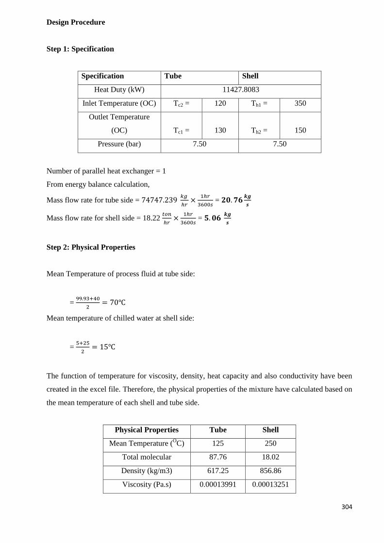
304
Design Procedure
Step 1: Specification
Specification Tube Shell
Heat Duty (kW) 11427.8083
Inlet Temperature (OC) Tc2 = 120 Th1 = 350
Outlet Temperature
(OC) Tc1 = 130 Th2 = 150
Pressure (bar) 7.50 7.50
Number of parallel heat exchanger = 1
From energy balance calculation,
Mass flow rate for tube side = 74747.239 𝑘𝑔
ℎ𝑟×
1ℎ𝑟
3600𝑠 = 𝟐𝟎. 𝟕𝟔
𝒌𝒈
𝒔
Mass flow rate for shell side = 18.22 𝑡𝑜𝑛
ℎ𝑟×
1ℎ𝑟
3600𝑠 = 𝟓. 𝟎𝟔
𝒌𝒈
𝒔
Step 2: Physical Properties
Mean Temperature of process fluid at tube side:
= 99.93+40
2= 70℃
Mean temperature of chilled water at shell side:
= 5+25
2= 15℃
The function of temperature for viscosity, density, heat capacity and also conductivity have been
created in the excel file. Therefore, the physical properties of the mixture have calculated based on
the mean temperature of each shell and tube side.
Physical Properties Tube Shell
Mean Temperature (OC) 125 250
Total molecular 87.76 18.02
Density (kg/m3) 617.25 856.86
Viscosity (Pa.s) 0.00013991 0.00013251
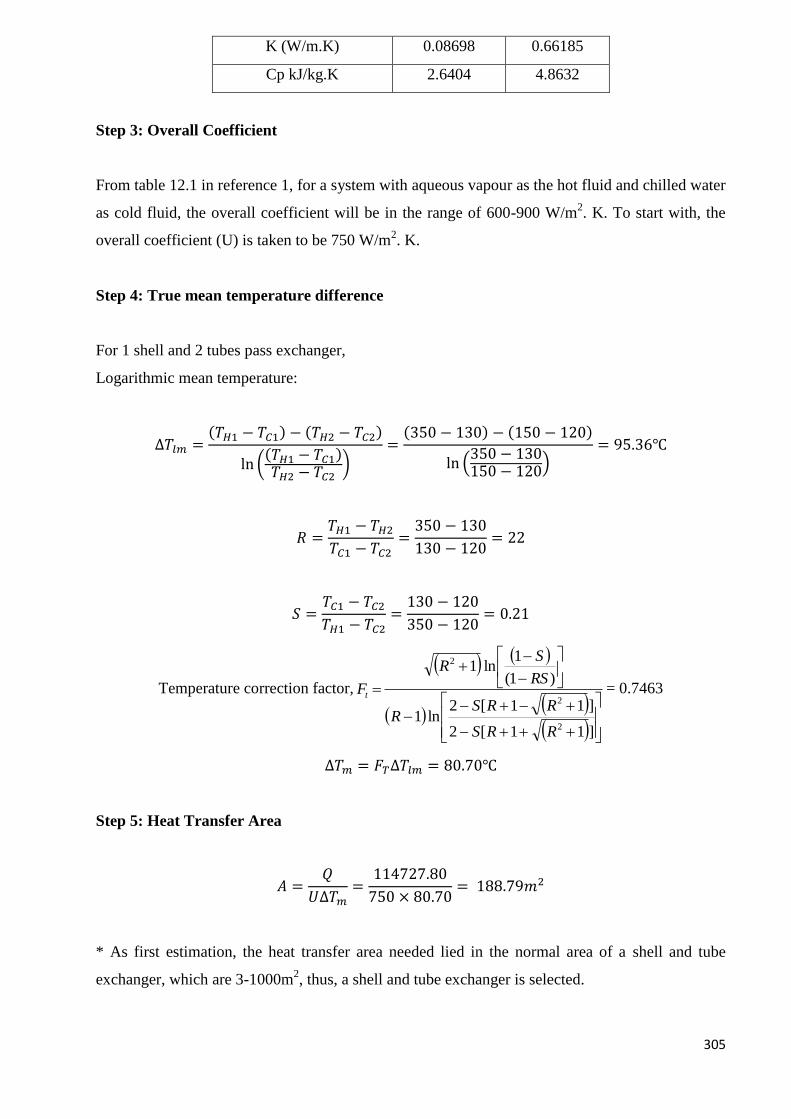
305
K (W/m.K) 0.08698 0.66185
Cp kJ/kg.K 2.6404 4.8632
Step 3: Overall Coefficient
From table 12.1 in reference 1, for a system with aqueous vapour as the hot fluid and chilled water
as cold fluid, the overall coefficient will be in the range of 600-900 W/m2. K. To start with, the
overall coefficient (U) is taken to be 750 W/m2. K.
Step 4: True mean temperature difference
For 1 shell and 2 tubes pass exchanger,
Logarithmic mean temperature:
∆𝑇𝑙𝑚 =(𝑇𝐻1 − 𝑇𝐶1) − (𝑇𝐻2 − 𝑇𝐶2)
ln ((𝑇𝐻1 − 𝑇𝐶1)𝑇𝐻2 − 𝑇𝐶2
)=
(350 − 130) − (150 − 120)
ln (350 − 130150 − 120
)= 95.36℃
𝑅 =𝑇𝐻1 − 𝑇𝐻2
𝑇𝐶1 − 𝑇𝐶2=
350 − 130
130 − 120= 22
𝑆 =𝑇𝐶1 − 𝑇𝐶2
𝑇𝐻1 − 𝑇𝐶2=
130 − 120
350 − 120= 0.21
Temperature correction factor,
]11[2
]11[2ln1
)1(
1ln1
2
2
2
RRS
RRSR
RS
SR
Ft= 0.7463
∆𝑇𝑚 = 𝐹𝑇∆𝑇𝑙𝑚 = 80.70℃
Step 5: Heat Transfer Area
𝐴 =𝑄
𝑈∆𝑇𝑚=
114727.80
750 × 80.70= 188.79𝑚2
* As first estimation, the heat transfer area needed lied in the normal area of a shell and tube
exchanger, which are 3-1000m2, thus, a shell and tube exchanger is selected.
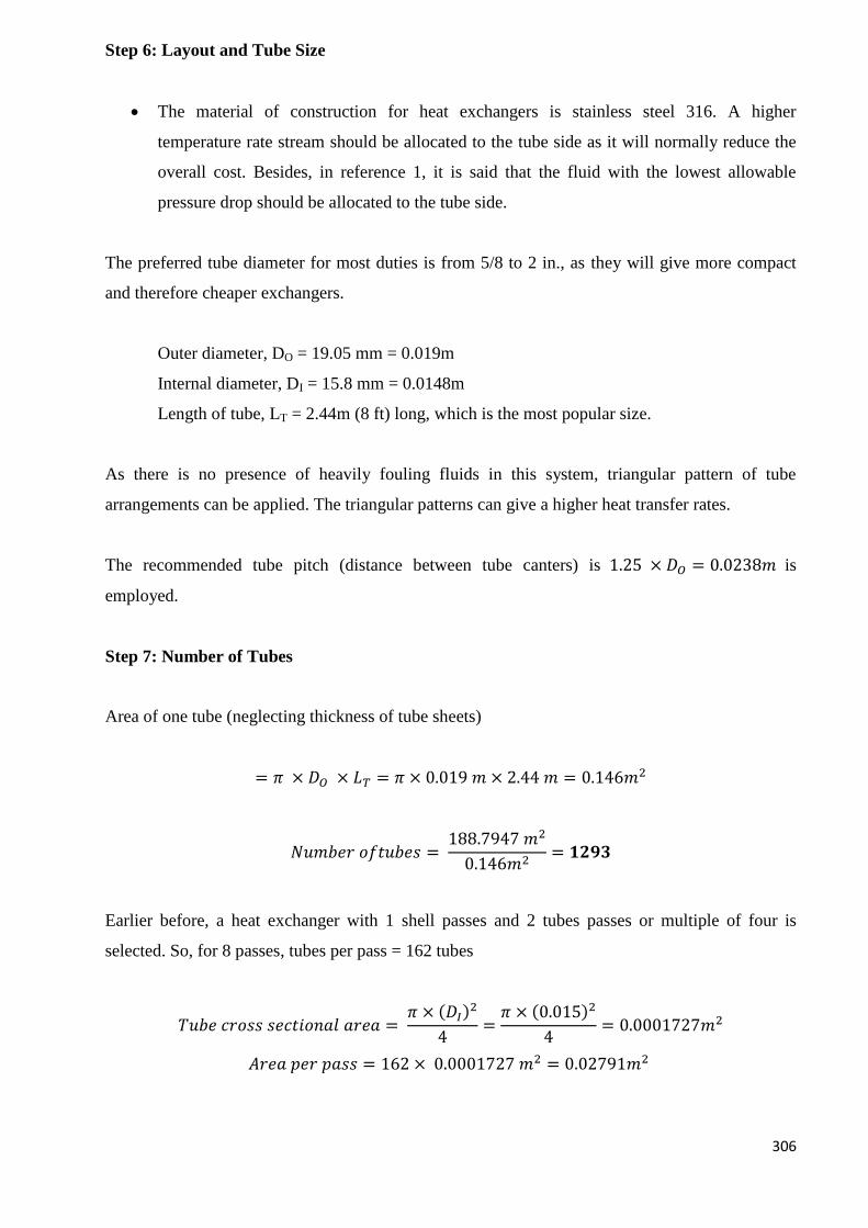
306
Step 6: Layout and Tube Size
The material of construction for heat exchangers is stainless steel 316. A higher
temperature rate stream should be allocated to the tube side as it will normally reduce the
overall cost. Besides, in reference 1, it is said that the fluid with the lowest allowable
pressure drop should be allocated to the tube side.
The preferred tube diameter for most duties is from 5/8 to 2 in., as they will give more compact
and therefore cheaper exchangers.
Outer diameter, DO = 19.05 mm = 0.019m
Internal diameter, DI = 15.8 mm = 0.0148m
Length of tube, LT = 2.44m (8 ft) long, which is the most popular size.
As there is no presence of heavily fouling fluids in this system, triangular pattern of tube
arrangements can be applied. The triangular patterns can give a higher heat transfer rates.
The recommended tube pitch (distance between tube canters) is 1.25 × 𝐷𝑂 = 0.0238𝑚 is
employed.
Step 7: Number of Tubes
Area of one tube (neglecting thickness of tube sheets)
= 𝜋 × 𝐷𝑂 × 𝐿𝑇 = 𝜋 × 0.019 𝑚 × 2.44 𝑚 = 0.146𝑚2
𝑁𝑢𝑚𝑏𝑒𝑟 𝑜𝑓𝑡𝑢𝑏𝑒𝑠 = 188.7947 𝑚2
0.146𝑚2= 𝟏𝟐𝟗𝟑
Earlier before, a heat exchanger with 1 shell passes and 2 tubes passes or multiple of four is
selected. So, for 8 passes, tubes per pass = 162 tubes
𝑇𝑢𝑏𝑒 𝑐𝑟𝑜𝑠𝑠 𝑠𝑒𝑐𝑡𝑖𝑜𝑛𝑎𝑙 𝑎𝑟𝑒𝑎 = 𝜋 × (𝐷𝐼)
2
4=
𝜋 × (0.015)2
4= 0.0001727𝑚2
𝐴𝑟𝑒𝑎 𝑝𝑒𝑟 𝑝𝑎𝑠𝑠 = 162 × 0.0001727 𝑚2 = 0.02791𝑚2
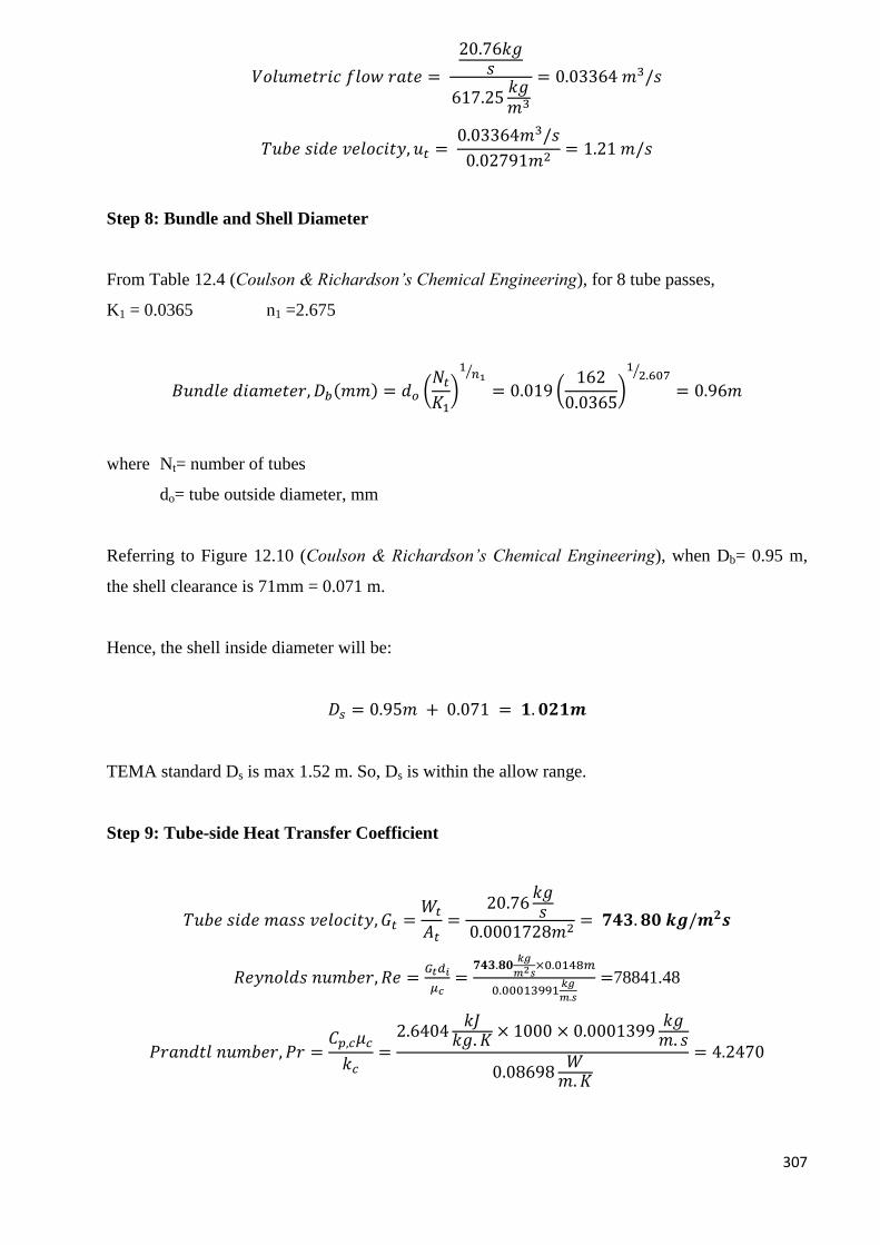
307
𝑉𝑜𝑙𝑢𝑚𝑒𝑡𝑟𝑖𝑐 𝑓𝑙𝑜𝑤 𝑟𝑎𝑡𝑒 =
20.76𝑘𝑔𝑠
617.25𝑘𝑔𝑚3
= 0.03364 𝑚3/𝑠
𝑇𝑢𝑏𝑒 𝑠𝑖𝑑𝑒 𝑣𝑒𝑙𝑜𝑐𝑖𝑡𝑦, 𝑢𝑡 = 0.03364𝑚3/𝑠
0.02791𝑚2= 1.21 𝑚/𝑠
Step 8: Bundle and Shell Diameter
From Table 12.4 (Coulson & Richardson’s Chemical Engineering), for 8 tube passes,
K1 = 0.0365 n1 =2.675
𝐵𝑢𝑛𝑑𝑙𝑒 𝑑𝑖𝑎𝑚𝑒𝑡𝑒𝑟, 𝐷𝑏(𝑚𝑚) = 𝑑𝑜 (𝑁𝑡
𝐾1)
1𝑛1
⁄
= 0.019 (162
0.0365)
12.607⁄
= 0.96𝑚
where Nt= number of tubes
do= tube outside diameter, mm
Referring to Figure 12.10 (Coulson & Richardson’s Chemical Engineering), when Db= 0.95 m,
the shell clearance is 71mm = 0.071 m.
Hence, the shell inside diameter will be:
𝐷𝑠 = 0.95𝑚 + 0.071 = 𝟏. 𝟎𝟐𝟏𝒎
TEMA standard Ds is max 1.52 m. So, Ds is within the allow range.
Step 9: Tube-side Heat Transfer Coefficient
𝑇𝑢𝑏𝑒 𝑠𝑖𝑑𝑒 𝑚𝑎𝑠𝑠 𝑣𝑒𝑙𝑜𝑐𝑖𝑡𝑦, 𝐺𝑡 =𝑊𝑡
𝐴𝑡=
20.76𝑘𝑔𝑠
0.0001728𝑚2= 𝟕𝟒𝟑. 𝟖𝟎 𝒌𝒈/𝒎𝟐𝒔
𝑅𝑒𝑦𝑛𝑜𝑙𝑑𝑠 𝑛𝑢𝑚𝑏𝑒𝑟, 𝑅𝑒 =𝐺𝑡𝑑𝑖
𝜇𝑐=
𝟕𝟒𝟑.𝟖𝟎𝑘𝑔
𝑚2𝑠×0.0148𝑚
0.00013991𝑘𝑔
𝑚.𝑠
=78841.48
𝑃𝑟𝑎𝑛𝑑𝑡𝑙 𝑛𝑢𝑚𝑏𝑒𝑟, 𝑃𝑟 =𝐶𝑝,𝑐𝜇𝑐
𝑘𝑐=
2.6404𝑘𝐽
𝑘𝑔. 𝐾× 1000 × 0.0001399
𝑘𝑔𝑚. 𝑠
0.08698𝑊
𝑚.𝐾
= 4.2470
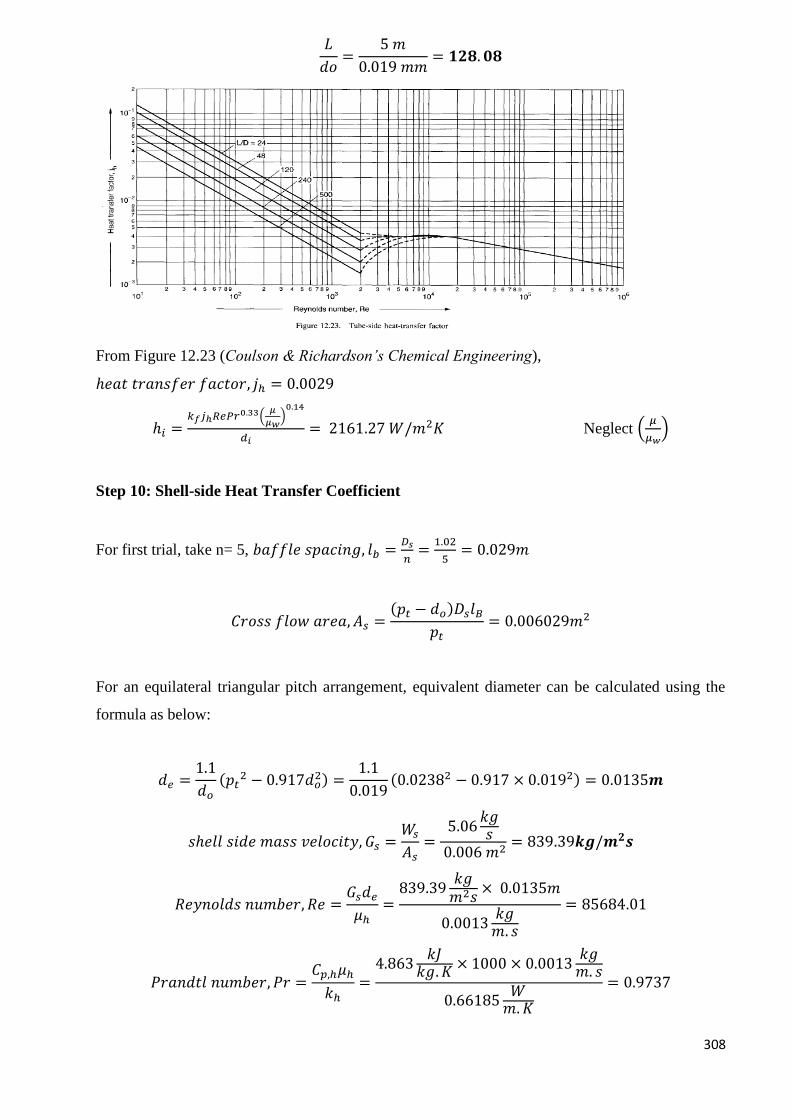
308
𝐿
𝑑𝑜=
5 𝑚
0.019 𝑚𝑚= 𝟏𝟐𝟖. 𝟎𝟖
From Figure 12.23 (Coulson & Richardson’s Chemical Engineering),
ℎ𝑒𝑎𝑡 𝑡𝑟𝑎𝑛𝑠𝑓𝑒𝑟 𝑓𝑎𝑐𝑡𝑜𝑟, 𝑗ℎ = 0.0029
ℎ𝑖 =𝑘𝑓𝑗ℎ𝑅𝑒𝑃𝑟0.33(
𝜇
𝜇𝑤)0.14
𝑑𝑖= 2161.27 𝑊/𝑚2𝐾 Neglect (
𝜇
𝜇𝑤)
Step 10: Shell-side Heat Transfer Coefficient
For first trial, take n= 5, 𝑏𝑎𝑓𝑓𝑙𝑒 𝑠𝑝𝑎𝑐𝑖𝑛𝑔, 𝑙𝑏 =𝐷𝑠
𝑛=
1.02
5= 0.029𝑚
𝐶𝑟𝑜𝑠𝑠 𝑓𝑙𝑜𝑤 𝑎𝑟𝑒𝑎, 𝐴𝑠 =(𝑝𝑡 − 𝑑𝑜)𝐷𝑠𝑙𝐵
𝑝𝑡= 0.006029𝑚2
For an equilateral triangular pitch arrangement, equivalent diameter can be calculated using the
formula as below:
𝑑𝑒 =1.1
𝑑𝑜
(𝑝𝑡2 − 0.917𝑑𝑜
2) =1.1
0.019(0.02382 − 0.917 × 0.0192) = 0.0135𝒎
𝑠ℎ𝑒𝑙𝑙 𝑠𝑖𝑑𝑒 𝑚𝑎𝑠𝑠 𝑣𝑒𝑙𝑜𝑐𝑖𝑡𝑦, 𝐺𝑠 =𝑊𝑠
𝐴𝑠=
5.06𝑘𝑔𝑠
0.006 𝑚2= 839.39𝒌𝒈/𝒎𝟐𝒔
𝑅𝑒𝑦𝑛𝑜𝑙𝑑𝑠 𝑛𝑢𝑚𝑏𝑒𝑟, 𝑅𝑒 =𝐺𝑠𝑑𝑒
𝜇ℎ=
839.39𝑘𝑔𝑚2𝑠
× 0.0135𝑚
0.0013𝑘𝑔𝑚. 𝑠
= 85684.01
𝑃𝑟𝑎𝑛𝑑𝑡𝑙 𝑛𝑢𝑚𝑏𝑒𝑟, 𝑃𝑟 =𝐶𝑝,ℎ𝜇ℎ
𝑘ℎ=
4.863𝑘𝐽
𝑘𝑔. 𝐾× 1000 × 0.0013
𝑘𝑔𝑚. 𝑠
0.66185𝑊
𝑚.𝐾
= 0.9737
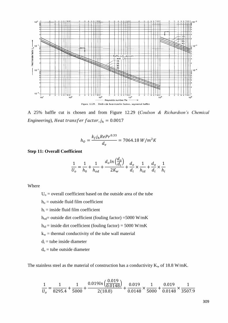
309
A 25% baffle cut is chosen and from Figure 12.29 (Coulson & Richardson’s Chemical
Engineering), 𝐻𝑒𝑎𝑡 𝑡𝑟𝑎𝑛𝑠𝑓𝑒𝑟 𝑓𝑎𝑐𝑡𝑜𝑟, 𝑗ℎ = 0.0017
ℎ𝑂 =𝑘𝑓𝑗ℎ𝑅𝑒𝑃𝑟0.33
𝑑𝑒= 7064.18 𝑊/𝑚2𝐾
Step 11: Overall Coefficient
1
𝑈𝑜=
1
ℎ0+
1
ℎ𝑜𝑑+
𝑑𝑜𝑙𝑛 (𝑑𝑜
𝑑𝑖)
2𝐾𝑤+
𝑑𝑜
𝑑𝑖×
1
ℎ𝑖𝑑+
𝑑𝑜
𝑑𝑖×
1
ℎ𝑖
Where
Uo = overall coefficient based on the outside area of the tube
ho = outside fluid film coefficient
hi = inside fluid film coefficient
hod= outside dirt coefficient (fouling factor) =5000 W/mK
hid = inside dirt coefficient (fouling factor) = 5000 W/mK
kw = thermal conductivity of the tube wall material
di = tube inside diameter
do = tube outside diameter
The stainless steel as the material of construction has a conductivity Kw of 18.8 W/mK.
1
𝑈𝑜=
1
8295.4+
1
5000+
0.019𝑙𝑛 (0.0190.0148)
2(18.8)+
0.019
0.0148×
1
5000+
0.019
0.0148×
1
3507.9
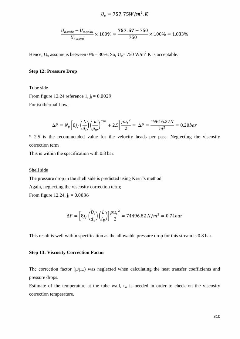
310
𝑈𝑜 = 𝟕𝟓𝟕. 𝟕𝟓𝑾/𝒎𝟐. 𝑲
𝑈𝑜,𝑐𝑎𝑙𝑐 − 𝑈𝑜,𝑎𝑠𝑠𝑢
𝑈𝑜,𝑎𝑠𝑠𝑢× 100% =
𝟕𝟓𝟕. 𝟓𝟕 − 750
750× 100% = 1.033%
Hence, Uo assume is between 0% – 30%. So, Uo= 750 W/m2 K is acceptable.
Step 12: Pressure Drop
Tube side
From figure 12.24 reference 1, jf = 0.0029
For isothermal flow,
∆𝑃 = 𝑁𝑝 [8𝑗𝑓 (𝐿
𝑑𝑖) (
𝜇
𝜇𝑤)−𝑚
+ 2.5]𝜌𝑢𝑡
2
2= ∆𝑃 =
19616.37𝑁
𝑚2= 0.20𝑏𝑎𝑟
* 2.5 is the recommended value for the velocity heads per pass. Neglecting the viscosity
correction term
This is within the specification with 0.8 bar.
Shell side
The pressure drop in the shell side is predicted using Kern‟s method.
Again, neglecting the viscosity correction term;
From figure 12.24, jf = 0.0036
∆𝑃 = [8𝑗𝑓 (𝐷𝑠
𝑑𝑒) (
𝐿
𝑙𝐵)]
𝜌𝑢𝑠2
2= 74496.82 𝑁/𝑚2 = 0.74𝑏𝑎𝑟
This result is well within specification as the allowable pressure drop for this stream is 0.8 bar.
Step 13: Viscosity Correction Factor
The correction factor (μ/μw) was neglected when calculating the heat transfer coefficients and
pressure drops.
Estimate of the temperature at the tube wall, tw is needed in order to check on the viscosity
correction temperature.
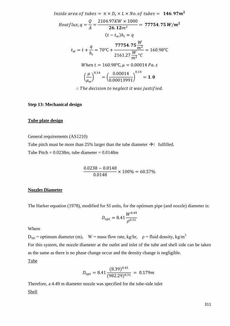
311
𝐼𝑛𝑠𝑖𝑑𝑒 𝑎𝑟𝑒𝑎 𝑜𝑓 𝑡𝑢𝑏𝑒𝑠 = 𝜋 × 𝐷𝐼 × 𝐿 × 𝑁𝑜. 𝑜𝑓 𝑡𝑢𝑏𝑒𝑠 = 𝟏𝟒𝟔. 𝟗𝟕𝒎𝟐
𝐻𝑒𝑎𝑡𝑓𝑙𝑢𝑥, 𝑞 =𝑄
𝐴=
2104.97𝐾𝑊 × 1000
𝟐𝟔. 𝟏𝟐𝑚2= 𝟕𝟕𝟕𝟓𝟒. 𝟕𝟓 𝑾/𝒎𝟐
(𝑡 − 𝑡𝑤)ℎ𝑖 = 𝑞
𝑡𝑤 = 𝑡 +𝑞
ℎ𝑖= 70℃ +
𝟕𝟕𝟕𝟓𝟒. 𝟕𝟓𝑊𝑚2
2161.27𝑊𝑚2 °𝐶
= 160.98℃
𝑊ℎ𝑒𝑛 𝑡 = 160.98℃, 𝜇 = 0.00014 𝑃𝑎. 𝑠
(𝜇
𝜇𝑤)0.14
= (0.00014
0.00013991)0.14
= 𝟏. 𝟎
∴ 𝑇ℎ𝑒 𝑑𝑒𝑐𝑖𝑠𝑖𝑜𝑛 𝑡𝑜 𝑛𝑒𝑔𝑙𝑒𝑐𝑡 𝑖𝑡 𝑤𝑎𝑠 𝑗𝑢𝑠𝑡𝑖𝑓𝑖𝑒𝑑.
Step 13: Mechanical design
Tube plate design
General requirements (AS1210)
Tube pitch must be more than 25% larger than the tube diameter fulfilled.
Tube Pitch = 0.0238m, tube diameter = 0.0148m
0.0238 − 0.0148
0.0148× 100% = 60.57%
Nozzles Diameter
The Harker equation (1978), modified for SI units, for the optimum pipe (and nozzle) diameter is:
𝐷𝑜𝑝𝑡 = 8.41𝑊0.45
𝜌0.31
Where
Dopt = optimum diameter (m), W = mass flow rate, kg/hr, ρ = fluid density, kg/m3
For this system, the nozzle diameter at the outlet and inlet of the tube and shell side can be taken
as the same as there is no phase change occur and the density change is negligible.
Tube
𝐷𝑜𝑝𝑡 = 8.41(8.39)0.45
(982.29)0.31 = 0.179𝑚
Therefore, a 4.49 m diameter nozzle was specified for the tube-side inlet
Shell
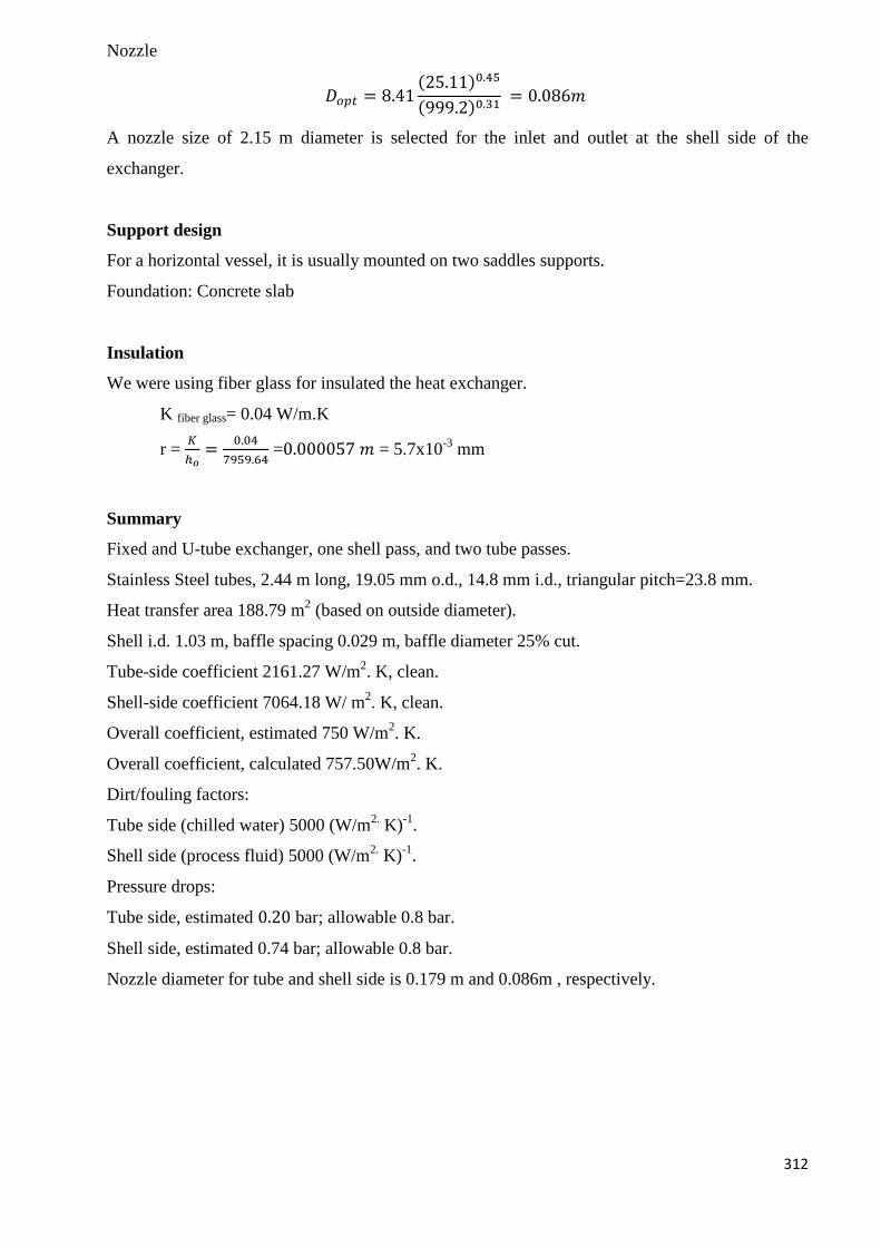
312
Nozzle
𝐷𝑜𝑝𝑡 = 8.41(25.11)0.45
(999.2)0.31 = 0.086𝑚
A nozzle size of 2.15 m diameter is selected for the inlet and outlet at the shell side of the
exchanger.
Support design
For a horizontal vessel, it is usually mounted on two saddles supports.
Foundation: Concrete slab
Insulation
We were using fiber glass for insulated the heat exchanger.
K fiber glass= 0.04 W/m.K
r = 𝐾
ℎ𝑜=
0.04
7959.64 =0.000057 𝑚 = 5.7x10
-3 mm
Summary
Fixed and U-tube exchanger, one shell pass, and two tube passes.
Stainless Steel tubes, 2.44 m long, 19.05 mm o.d., 14.8 mm i.d., triangular pitch=23.8 mm.
Heat transfer area 188.79 m2 (based on outside diameter).
Shell i.d. 1.03 m, baffle spacing 0.029 m, baffle diameter 25% cut.
Tube-side coefficient 2161.27 W/m2. K, clean.
Shell-side coefficient 7064.18 W/ m2. K, clean.
Overall coefficient, estimated 750 W/m2. K.
Overall coefficient, calculated 757.50W/m2. K.
Dirt/fouling factors:
Tube side (chilled water) 5000 (W/m2. K)
-1.
Shell side (process fluid) 5000 (W/m2. K)
-1.
Pressure drops:
Tube side, estimated 0.20 bar; allowable 0.8 bar.
Shell side, estimated 0.74 bar; allowable 0.8 bar.
Nozzle diameter for tube and shell side is 0.179 m and 0.086m , respectively.
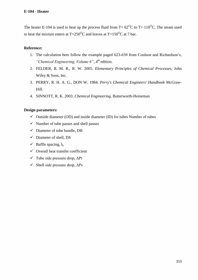
313
E-104 - Heater
The heater E-104 is used to heat up the process fluid from T= 62OC to T= 110
OC. The steam used
to heat the mixture enters at T=250OC and leaves at T=150
OC at 7 bar.
Reference:
1. The calculation here follow the example paged 623-630 from Coulson and Richardson’s,
“Chemical Engineering, Volume 6”, 4th
edition.
2. FELDER, R. M. R., R. W. 2005. Elementary Principles of Chemical Processes, John
Wiley & Sons, Inc.
3. PERRY, R. H. A. G., DON W. 1984. Perry's Chemical Engineers' Handbook McGraw-
Hill.
4. SINNOTT, R. K. 2003. Chemical Engineering, Butterworth-Heineman
Design parameters:
Outside diameter (OD) and inside diameter (ID) for tubes Number of tubes
Number of tube passes and shell passes
Diameter of tube bundle, DB
Diameter of shell, DS
Baffle spacing, lb
Overall heat transfer coefficient
Tube side pressure drop, ΔPt
Shell side pressure drop, ΔPs
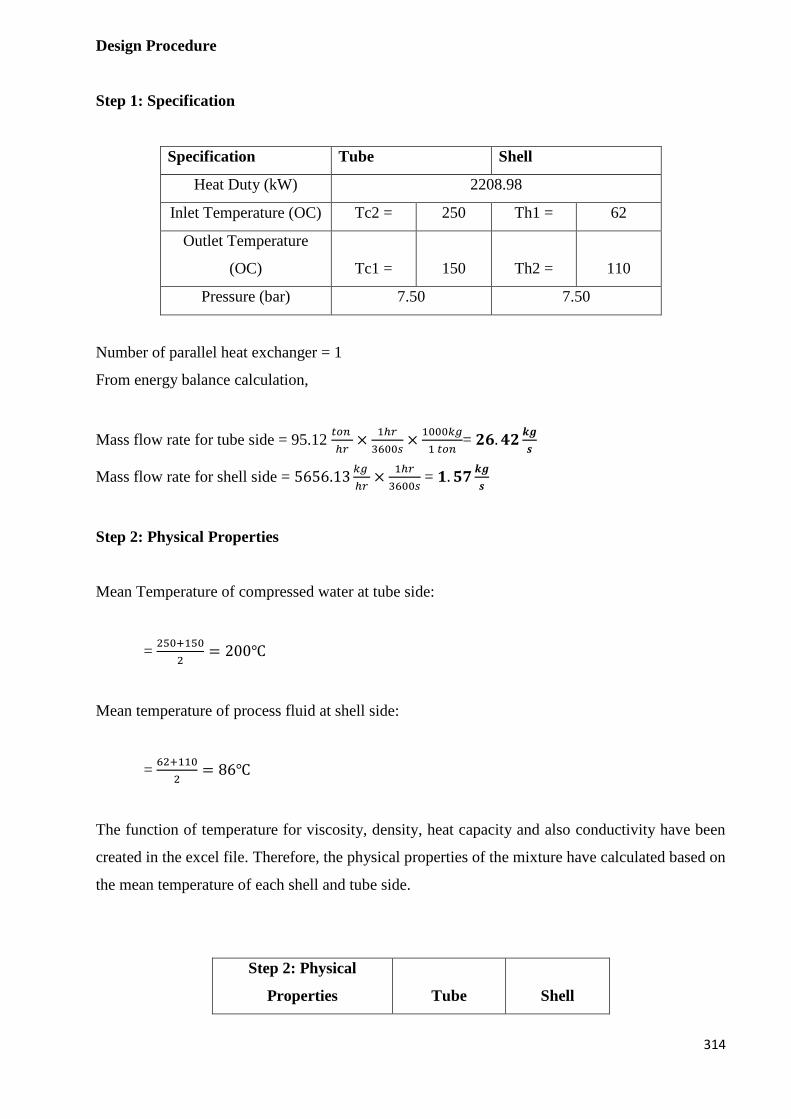
314
Design Procedure
Step 1: Specification
Specification Tube Shell
Heat Duty (kW) 2208.98
Inlet Temperature (OC) Tc2 = 250 Th1 = 62
Outlet Temperature
(OC) Tc1 = 150 Th2 = 110
Pressure (bar) 7.50 7.50
Number of parallel heat exchanger = 1
From energy balance calculation,
Mass flow rate for tube side = 95.12 𝑡𝑜𝑛
ℎ𝑟×
1ℎ𝑟
3600𝑠×
1000𝑘𝑔
1 𝑡𝑜𝑛= 𝟐𝟔. 𝟒𝟐
𝒌𝒈
𝒔
Mass flow rate for shell side = 5656.13𝑘𝑔
ℎ𝑟×
1ℎ𝑟
3600𝑠 = 𝟏. 𝟓𝟕
𝒌𝒈
𝒔
Step 2: Physical Properties
Mean Temperature of compressed water at tube side:
= 250+150
2= 200℃
Mean temperature of process fluid at shell side:
= 62+110
2= 86℃
The function of temperature for viscosity, density, heat capacity and also conductivity have been
created in the excel file. Therefore, the physical properties of the mixture have calculated based on
the mean temperature of each shell and tube side.
Step 2: Physical
Properties Tube Shell
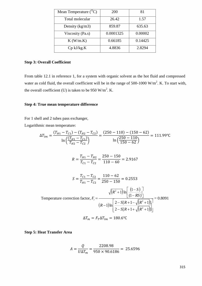
315
Mean Temperature (OC) 200 81
Total molecular 26.42 1.57
Density (kg/m3) 859.87 635.63
Viscosity (Pa.s) 0.0001325 0.00002
K (W/m.K) 0.66185 0.14425
Cp kJ/kg.K 4.8836 2.8294
Step 3: Overall Coefficient
From table 12.1 in reference 1, for a system with organic solvent as the hot fluid and compressed
water as cold fluid, the overall coefficient will be in the range of 500-1000 W/m2. K. To start with,
the overall coefficient (U) is taken to be 950 W/m2. K.
Step 4: True mean temperature difference
For 1 shell and 2 tubes pass exchanger,
Logarithmic mean temperature:
∆𝑇𝑙𝑚 =(𝑇𝐻1 − 𝑇𝐶1) − (𝑇𝐻2 − 𝑇𝐶2)
ln ((𝑇𝐻1 − 𝑇𝐶1)𝑇𝐻2 − 𝑇𝐶2
)=
(250 − 110) − (150 − 62)
ln (250 − 110150 − 62
)= 111.99℃
𝑅 =𝑇𝐻1 − 𝑇𝐻2
𝑇𝐶1 − 𝑇𝐶2=
250 − 150
110 − 60= 2.9167
𝑆 =𝑇𝐶1 − 𝑇𝐶2
𝑇𝐻1 − 𝑇𝐶2=
110 − 62
250 − 150= 0.2553
Temperature correction factor,
]11[2
]11[2ln1
)1(
1ln1
2
2
2
RRS
RRSR
RS
SR
Ft = 0.8091
∆𝑇𝑚 = 𝐹𝑇∆𝑇𝑙𝑚 = 180.6℃
Step 5: Heat Transfer Area
𝐴 =𝑄
𝑈∆𝑇𝑚=
2208.98
950 × 90.6186= 25.6596
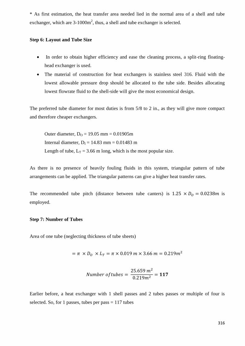
316
* As first estimation, the heat transfer area needed lied in the normal area of a shell and tube
exchanger, which are 3-1000m2, thus, a shell and tube exchanger is selected.
Step 6: Layout and Tube Size
In order to obtain higher efficiency and ease the cleaning process, a split-ring floating-
head exchanger is used.
The material of construction for heat exchangers is stainless steel 316. Fluid with the
lowest allowable pressure drop should be allocated to the tube side. Besides allocating
lowest flowrate fluid to the shell-side will give the most economical design.
The preferred tube diameter for most duties is from 5/8 to 2 in., as they will give more compact
and therefore cheaper exchangers.
Outer diameter, DO = 19.05 mm = 0.01905m
Internal diameter, DI = 14.83 mm = 0.01483 m
Length of tube, LT = 3.66 m long, which is the most popular size.
As there is no presence of heavily fouling fluids in this system, triangular pattern of tube
arrangements can be applied. The triangular patterns can give a higher heat transfer rates.
The recommended tube pitch (distance between tube canters) is 1.25 × 𝐷𝑂 = 0.0238𝑚 is
employed.
Step 7: Number of Tubes
Area of one tube (neglecting thickness of tube sheets)
= 𝜋 × 𝐷𝑂 × 𝐿𝑇 = 𝜋 × 0.019 𝑚 × 3.66 𝑚 = 0.219𝑚2
𝑁𝑢𝑚𝑏𝑒𝑟 𝑜𝑓𝑡𝑢𝑏𝑒𝑠 = 25.659 𝑚2
0.219𝑚2= 𝟏𝟏𝟕
Earlier before, a heat exchanger with 1 shell passes and 2 tubes passes or multiple of four is
selected. So, for 1 passes, tubes per pass = 117 tubes
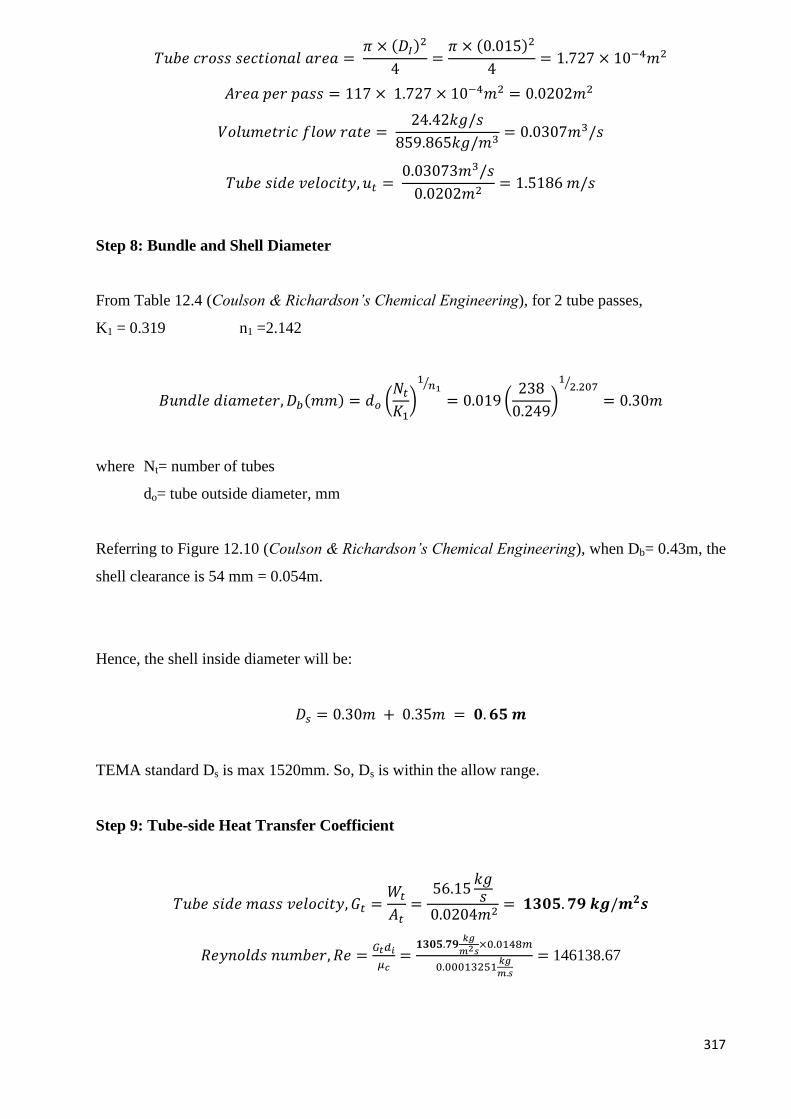
317
𝑇𝑢𝑏𝑒 𝑐𝑟𝑜𝑠𝑠 𝑠𝑒𝑐𝑡𝑖𝑜𝑛𝑎𝑙 𝑎𝑟𝑒𝑎 = 𝜋 × (𝐷𝐼)
2
4=
𝜋 × (0.015)2
4= 1.727 × 10⁻⁴𝑚2
𝐴𝑟𝑒𝑎 𝑝𝑒𝑟 𝑝𝑎𝑠𝑠 = 117 × 1.727 × 10−4𝑚2 = 0.0202𝑚2
𝑉𝑜𝑙𝑢𝑚𝑒𝑡𝑟𝑖𝑐 𝑓𝑙𝑜𝑤 𝑟𝑎𝑡𝑒 = 24.42𝑘𝑔/𝑠
859.865𝑘𝑔/𝑚3= 0.0307𝑚3/𝑠
𝑇𝑢𝑏𝑒 𝑠𝑖𝑑𝑒 𝑣𝑒𝑙𝑜𝑐𝑖𝑡𝑦, 𝑢𝑡 = 0.03073𝑚3/𝑠
0.0202𝑚2= 1.5186 𝑚/𝑠
Step 8: Bundle and Shell Diameter
From Table 12.4 (Coulson & Richardson’s Chemical Engineering), for 2 tube passes,
K1 = 0.319 n1 =2.142
𝐵𝑢𝑛𝑑𝑙𝑒 𝑑𝑖𝑎𝑚𝑒𝑡𝑒𝑟, 𝐷𝑏(𝑚𝑚) = 𝑑𝑜 (𝑁𝑡
𝐾1)
1𝑛1
⁄
= 0.019 (238
0.249)
12.207⁄
= 0.30𝑚
where Nt= number of tubes
do= tube outside diameter, mm
Referring to Figure 12.10 (Coulson & Richardson’s Chemical Engineering), when Db= 0.43m, the
shell clearance is 54 mm = 0.054m.
Hence, the shell inside diameter will be:
𝐷𝑠 = 0.30𝑚 + 0.35𝑚 = 𝟎. 𝟔𝟓 𝒎
TEMA standard Ds is max 1520mm. So, Ds is within the allow range.
Step 9: Tube-side Heat Transfer Coefficient
𝑇𝑢𝑏𝑒 𝑠𝑖𝑑𝑒 𝑚𝑎𝑠𝑠 𝑣𝑒𝑙𝑜𝑐𝑖𝑡𝑦, 𝐺𝑡 =𝑊𝑡
𝐴𝑡=
56.15𝑘𝑔𝑠
0.0204𝑚2= 𝟏𝟑𝟎𝟓. 𝟕𝟗 𝒌𝒈/𝒎𝟐𝒔
𝑅𝑒𝑦𝑛𝑜𝑙𝑑𝑠 𝑛𝑢𝑚𝑏𝑒𝑟, 𝑅𝑒 =𝐺𝑡𝑑𝑖
𝜇𝑐=
𝟏𝟑𝟎𝟓.𝟕𝟗𝑘𝑔
𝑚2𝑠×0.0148𝑚
0.00013251𝑘𝑔
𝑚.𝑠
= 146138.67
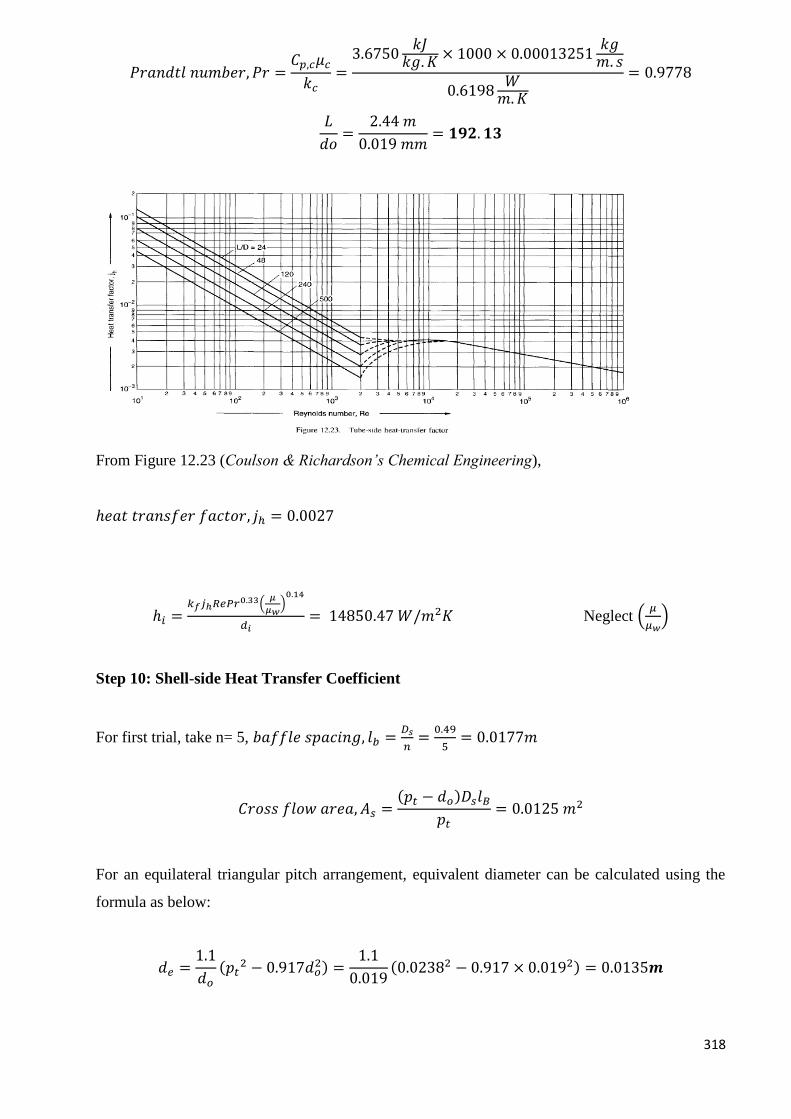
318
𝑃𝑟𝑎𝑛𝑑𝑡𝑙 𝑛𝑢𝑚𝑏𝑒𝑟, 𝑃𝑟 =𝐶𝑝,𝑐𝜇𝑐
𝑘𝑐=
3.6750𝑘𝐽
𝑘𝑔. 𝐾× 1000 × 0.00013251
𝑘𝑔𝑚. 𝑠
0.6198𝑊
𝑚.𝐾
= 0.9778
𝐿
𝑑𝑜=
2.44 𝑚
0.019 𝑚𝑚= 𝟏𝟗𝟐. 𝟏𝟑
From Figure 12.23 (Coulson & Richardson’s Chemical Engineering),
ℎ𝑒𝑎𝑡 𝑡𝑟𝑎𝑛𝑠𝑓𝑒𝑟 𝑓𝑎𝑐𝑡𝑜𝑟, 𝑗ℎ = 0.0027
ℎ𝑖 =𝑘𝑓𝑗ℎ𝑅𝑒𝑃𝑟0.33(
𝜇
𝜇𝑤)0.14
𝑑𝑖= 14850.47 𝑊/𝑚2𝐾 Neglect (
𝜇
𝜇𝑤)
Step 10: Shell-side Heat Transfer Coefficient
For first trial, take n= 5, 𝑏𝑎𝑓𝑓𝑙𝑒 𝑠𝑝𝑎𝑐𝑖𝑛𝑔, 𝑙𝑏 =𝐷𝑠
𝑛=
0.49
5= 0.0177𝑚
𝐶𝑟𝑜𝑠𝑠 𝑓𝑙𝑜𝑤 𝑎𝑟𝑒𝑎, 𝐴𝑠 =(𝑝𝑡 − 𝑑𝑜)𝐷𝑠𝑙𝐵
𝑝𝑡= 0.0125 𝑚2
For an equilateral triangular pitch arrangement, equivalent diameter can be calculated using the
formula as below:
𝑑𝑒 =1.1
𝑑𝑜
(𝑝𝑡2 − 0.917𝑑𝑜
2) =1.1
0.019(0.02382 − 0.917 × 0.0192) = 0.0135𝒎
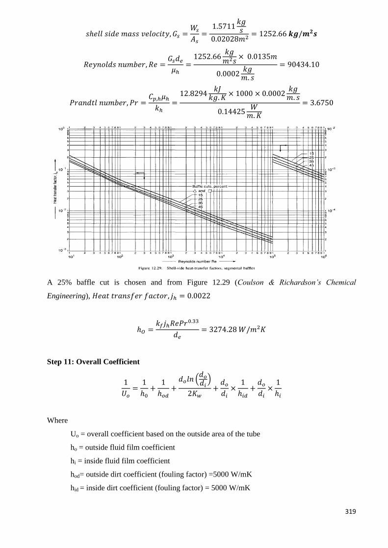
319
𝑠ℎ𝑒𝑙𝑙 𝑠𝑖𝑑𝑒 𝑚𝑎𝑠𝑠 𝑣𝑒𝑙𝑜𝑐𝑖𝑡𝑦, 𝐺𝑠 =𝑊𝑠
𝐴𝑠=
1.5711𝑘𝑔𝑠
0.02028𝑚2= 1252.66 𝒌𝒈/𝒎𝟐𝒔
𝑅𝑒𝑦𝑛𝑜𝑙𝑑𝑠 𝑛𝑢𝑚𝑏𝑒𝑟, 𝑅𝑒 =𝐺𝑠𝑑𝑒
𝜇ℎ=
1252.66𝑘𝑔𝑚2𝑠
× 0.0135𝑚
0.0002𝑘𝑔𝑚. 𝑠
= 90434.10
𝑃𝑟𝑎𝑛𝑑𝑡𝑙 𝑛𝑢𝑚𝑏𝑒𝑟, 𝑃𝑟 =𝐶𝑝,ℎ𝜇ℎ
𝑘ℎ=
12.8294𝑘𝐽
𝑘𝑔. 𝐾× 1000 × 0.0002
𝑘𝑔𝑚. 𝑠
0.14425𝑊
𝑚.𝐾
= 3.6750
A 25% baffle cut is chosen and from Figure 12.29 (Coulson & Richardson’s Chemical
Engineering), 𝐻𝑒𝑎𝑡 𝑡𝑟𝑎𝑛𝑠𝑓𝑒𝑟 𝑓𝑎𝑐𝑡𝑜𝑟, 𝑗ℎ = 0.0022
ℎ𝑂 =𝑘𝑓𝑗ℎ𝑅𝑒𝑃𝑟0.33
𝑑𝑒= 3274.28 𝑊/𝑚2𝐾
Step 11: Overall Coefficient
1
𝑈𝑜=
1
ℎ0+
1
ℎ𝑜𝑑+
𝑑𝑜𝑙𝑛 (𝑑𝑜
𝑑𝑖)
2𝐾𝑤+
𝑑𝑜
𝑑𝑖×
1
ℎ𝑖𝑑+
𝑑𝑜
𝑑𝑖×
1
ℎ𝑖
Where
Uo = overall coefficient based on the outside area of the tube
ho = outside fluid film coefficient
hi = inside fluid film coefficient
hod= outside dirt coefficient (fouling factor) =5000 W/mK
hid = inside dirt coefficient (fouling factor) = 5000 W/mK
320
kw = thermal conductivity of the tube wall material
di = tube inside diameter
do = tube outside diameter
The stainless steel as the material of construction has a conductivity Kw of 18.8 W/mK.
1
𝑈𝑜=
1
588.2+
1
5000+
0.019𝑙𝑛 (0.0190.0148)
2(18.8)+
0.019
0.0148×
1
5000+
0.019
0.0148×
1
14850.47
𝑈𝑜 = 𝟏𝟎𝟑𝟖𝑾/𝒎𝟐. 𝑲
𝑈𝑜,𝑐𝑎𝑙𝑐 − 𝑈𝑜,𝑎𝑠𝑠𝑢
𝑈𝑜,𝑎𝑠𝑠𝑢× 100% =
𝟏𝟎𝟑𝟖. 𝟕𝟔 − 950
950× 100% = 9.34%
Hence, Uo assume is between 0% – 30%. So, Uo= 1038 W/m2 K is acceptable.
Step 12: Pressure Drop
Tube side
From figure 12.24 reference 1, jf = 0.0027
For isothermal flow,
∆𝑃 = 𝑁𝑝 [8𝑗𝑓 (𝐿
𝑑𝑖) (
𝜇
𝜇𝑤)−𝑚
+ 2.5]𝜌𝑢𝑡
2
2= ∆𝑃 = 6593.28
𝑁
𝑚2= 0.065 𝑏𝑎𝑟
* 2.5 is the recommended value for the velocity heads per pass. Neglecting the viscosity
correction term
This is within the specification with 0.8 bar.
Shell side
The pressure drop in the shell side is predicted using Kern‟s method.
Again, neglecting the viscosity correction term;
From figure 12.24, jf = 0.0015
∆𝑃 = [8𝑗𝑓 (𝐷𝑠
𝑑𝑒) (
𝐿
𝑙𝐵)]
𝜌𝑢𝑠2
2= 80157
𝑁
𝑚2= 0.80158𝑏𝑎𝑟
This result is well within specification as the allowable pressure drop for this stream is 0.8 bar.
321
Step 13: Viscosity Correction Factor
The correction factor (μ/μw) was neglected when calculating the heat transfer coefficients and
pressure drops.
Estimate of the temperature at the tube wall, tw is needed in order to check on the viscosity
correction temperature.
𝐼𝑛𝑠𝑖𝑑𝑒 𝑎𝑟𝑒𝑎 𝑜𝑓 𝑡𝑢𝑏𝑒𝑠 = 𝜋 × 𝐷𝐼 × 𝐿 × 𝑁𝑜. 𝑜𝑓 𝑡𝑢𝑏𝑒𝑠 = 𝟏𝟗. 𝟓𝟖 𝒎𝟐
𝐻𝑒𝑎𝑡𝑓𝑙𝑢𝑥, 𝑞 =𝑄
𝐴=
2208.9778𝐾𝑊 × 1000
𝟏𝟗. 𝟓𝟖𝑚2= 𝟏𝟏𝟎𝟓𝟖𝟒. 𝟔𝟐𝑾/𝒎𝟐
(𝑡 − 𝑡𝑤)ℎ𝑖 = 𝑞
𝑡𝑤 = 𝑡 +𝑞
ℎ𝑖= 200℃ +
𝟏𝟏𝟎𝟓𝟖𝟒. 𝟔𝟐𝑊𝑚2
17479.26𝑊𝑚2 °𝐶
= 206.33℃
𝑊ℎ𝑒𝑛 𝑡 = 206.33℃, 𝜇 = 0.0008 𝑃𝑎. 𝑠
(𝜇
𝜇𝑤)0.14
= (0.00013251
0.00013)0.14
= 𝟏. 𝟎
∴ 𝑇ℎ𝑒 𝑑𝑒𝑐𝑖𝑠𝑖𝑜𝑛 𝑡𝑜 𝑛𝑒𝑔𝑙𝑒𝑐𝑡 𝑖𝑡 𝑤𝑎𝑠 𝑗𝑢𝑠𝑡𝑖𝑓𝑖𝑒𝑑.
Step 14: Mechanical design
Tube plate design
General requirements (AS1210)
Tube pitch must be more than 25% larger than the tube diameter fulfilled.
Tube Pitch = 0.0238m, tube diameter = 0.0148m
0.0238 − 0.0148
0.0148× 100% = 60.57%
Nozzles Diameter
The Harker equation (1978), modified for SI units, for the optimum pipe (and nozzle) diameter is:
𝐷𝑜𝑝𝑡 = 8.41𝑊0.45
𝜌0.31
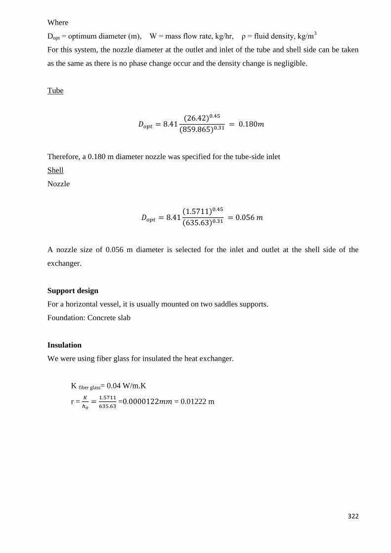
322
Where
Dopt = optimum diameter (m), W = mass flow rate, kg/hr, ρ = fluid density, kg/m3
For this system, the nozzle diameter at the outlet and inlet of the tube and shell side can be taken
as the same as there is no phase change occur and the density change is negligible.
Tube
𝐷𝑜𝑝𝑡 = 8.41(26.42)0.45
(859.865)0.31 = 0.180𝑚
Therefore, a 0.180 m diameter nozzle was specified for the tube-side inlet
Shell
Nozzle
𝐷𝑜𝑝𝑡 = 8.41(1.5711)0.45
(635.63)0.31 = 0.056 𝑚
A nozzle size of 0.056 m diameter is selected for the inlet and outlet at the shell side of the
exchanger.
Support design
For a horizontal vessel, it is usually mounted on two saddles supports.
Foundation: Concrete slab
Insulation
We were using fiber glass for insulated the heat exchanger.
K fiber glass= 0.04 W/m.K
r = 𝐾
ℎ𝑜=
1.5711
635.63 =0.0000122𝑚𝑚 = 0.01222 m
323
Summary
Split ring, floating head, one shell pass, and 1 tube passes.
Stainless Steel tubes, 3.66 m long, 19.05 mm o.d., 14.8 mm i.d., triangular pitch=23.8 mm.
Heat transfer area 25.66 m2 (based on outside diameter).
Shell i.d. 0.354 m, baffle spacing 0.0177 mm, baffle 25% cut.
Tube-side coefficient 17479.26 W/m2. K, clean.
Shell-side coefficient 3274.28 W/ m2. K, clean.
Overall coefficient, estimated 500 W/m2. K.
Overall coefficient, calculated 421.87 W/m2. K.
Dirt/fouling factors:
Tube side (compressed water) 5000 (W/m2.
K)-1
.
Shell side (process fluid) 5000 (W/m2. K)
-1.
Pressure drops:
Tube side, estimated 0.066 bar; allowable 0.8 bar.
Shell side, estimated 0.80 bar; allowable 0.8 bar.
Nozzle diameter for tube and shell side is 0.18 m and 0.056 m, respectively.
324
E-105 – Condenser
The condenser E-105 is used to condense the process mixture at 1 bar from T=38OC to T=
33OC.The brine solution used to condense the mixture enters at T=5
OC and leaves at T=15
OC at 1
bar.
Reference:
1. The calculation here follow the example paged 623-630 from Coulson and Richardson’s,
“Chemical Engineering, Volume 6”, 4th
edition.
2. FELDER, R. M. R., R. W. 2005. Elementary Principles of Chemical Processes, John
Wiley & Sons, Inc.
3. PERRY, R. H. A. G., DON W. 1984. Perry's Chemical Engineers' Handbook McGraw-
Hill.
4. SINNOTT, R. K. 2003. Chemical Engineering, Butterworth-Heineman
Design parameters:
Outside diameter (OD) and inside diameter (ID) for tubes Number of tubes
Number of tube passes and shell passes
Diameter of tube bundle, DB
Diameter of shell, DS
Baffle spacing, lb
Overall heat transfer coefficient
Tube side pressure drop, ΔPt
Shell side pressure drop, ΔPs
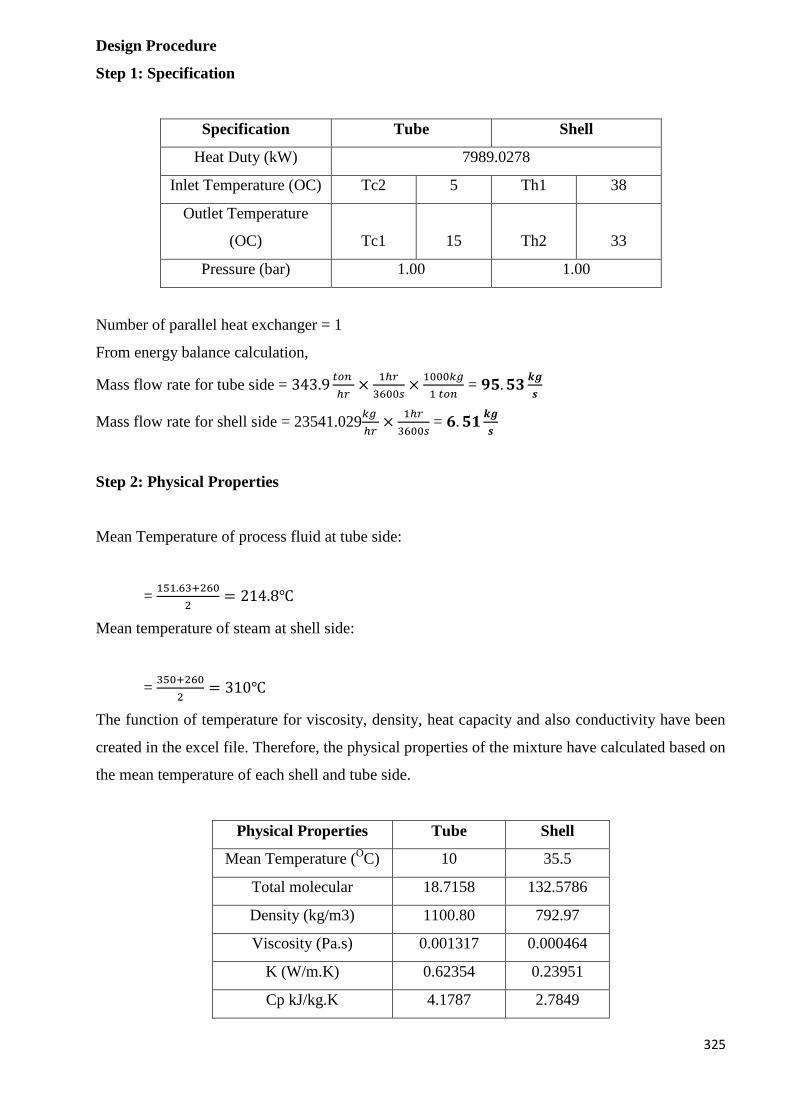
325
Design Procedure
Step 1: Specification
Specification Tube Shell
Heat Duty (kW) 7989.0278
Inlet Temperature (OC) Tc2 5 Th1 38
Outlet Temperature
(OC) Tc1 15 Th2 33
Pressure (bar) 1.00 1.00
Number of parallel heat exchanger = 1
From energy balance calculation,
Mass flow rate for tube side = 343.9𝑡𝑜𝑛
ℎ𝑟×
1ℎ𝑟
3600𝑠×
1000𝑘𝑔
1 𝑡𝑜𝑛 = 𝟗𝟓. 𝟓𝟑
𝒌𝒈
𝒔
Mass flow rate for shell side = 23541.029𝑘𝑔
ℎ𝑟×
1ℎ𝑟
3600𝑠 = 𝟔. 𝟓𝟏
𝒌𝒈
𝒔
Step 2: Physical Properties
Mean Temperature of process fluid at tube side:
= 151.63+260
2= 214.8℃
Mean temperature of steam at shell side:
= 350+260
2= 310℃
The function of temperature for viscosity, density, heat capacity and also conductivity have been
created in the excel file. Therefore, the physical properties of the mixture have calculated based on
the mean temperature of each shell and tube side.
Physical Properties Tube Shell
Mean Temperature (OC) 10 35.5
Total molecular 18.7158 132.5786
Density (kg/m3) 1100.80 792.97
Viscosity (Pa.s) 0.001317 0.000464
K (W/m.K) 0.62354 0.23951
Cp kJ/kg.K 4.1787 2.7849
326
Step 3: Overall Coefficient
From table 12.1 in reference 1, for a system with steam as the hot fluid and process fluid as cold
fluid, the overall coefficient will be in the range of 500-700 W/m2. K. To start with, the overall
coefficient (U) is taken to be 75W/m2. K.
Step 4: True mean temperature difference
For 1 shell and 2 tubes pass exchanger,
Logarithmic mean temperature:
∆𝑇𝑙𝑚 =(𝑇𝐻1 − 𝑇𝐶1) − (𝑇𝐻2 − 𝑇𝐶2)
ln ((𝑇𝐻1 − 𝑇𝐶1)𝑇𝐻2 − 𝑇𝐶2
)=
(38 − 15) − (33 − 5)
ln (38 − 1533 − 5
)= 25.4181℃
𝑅 =𝑇𝐻1 − 𝑇𝐻2
𝑇𝐶1 − 𝑇𝐶2=
5 − 33
33 − 38= 5.60
𝑆 =𝑇𝐶1 − 𝑇𝐶2
𝑇𝐻1 − 𝑇𝐶2=
33 − 38
38 − 5= 0.1515
Temperature correction factor,
]11[2
]11[2ln1
)1(
1ln1
2
2
2
RRS
RRSR
RS
SR
Ft = 0.8190
∆𝑇𝑚 = 𝐹𝑇∆𝑇𝑙𝑚 = 20.8163℃
Step 5: Heat Transfer Area
𝐴 =𝑄
𝑈∆𝑇𝑚=
1881.22
75 × 79.37= 697.79 𝑚2
* As first estimation, the heat transfer area needed lied in the normal area of a shell and tube
exchanger, which are 3-1000m2, thus, a shell and tube exchanger is selected.
Step 6: Layout and Tube Size
327
In order to obtain higher efficiency and ease the cleaning process, a split-ring floating-
head exchanger is used.
The material of construction for heat exchangers is stainless steel 316. A higher pressure
stream should be allocated to the tube side as high-pressure tube is cheaper than high-
pressure shell. Besides the more corrosive material should allocated to the tube side to
reduce cost.
The preferred tube diameter for most duties is from 5/8 to 2 in., as they will give more compact
and therefore cheaper exchangers.
Outer diameter, DO = 25 mm = 0.025m
Internal diameter, DI = 22.8 mm = 0.0228m
Length of tube, LT = 4.88m (16 ft) long, which is the most popular size.
As there is no presence of heavily fouling fluids in this system, triangular pattern of tube
arrangements can be applied. The triangular patterns can give a higher heat transfer rates.
The recommended tube pitch (distance between tube canters) is 1.25 × 𝐷𝑂 = 0.0313𝑚 is
employed.
Step 7: Number of Tubes
Area of one tube (neglecting thickness of tube sheets)
= 𝜋 × 𝐷𝑂 × 𝐿𝑇 = 𝜋 × 0.01905𝑚 × 5 𝑚 = 0.2992𝑚2
𝑁𝑢𝑚𝑏𝑒𝑟 𝑜𝑓𝑡𝑢𝑏𝑒𝑠 = 697.7940 𝑚2
0.2992𝑚2= 𝟐𝟑𝟑𝟐
Earlier before, a heat exchanger with 1 shell passes and 2 tubes passes or multiple of four is
selected. So, for 6 passes, tubes per pass = 389 tubes
𝑇𝑢𝑏𝑒 𝑐𝑟𝑜𝑠𝑠 𝑠𝑒𝑐𝑡𝑖𝑜𝑛𝑎𝑙 𝑎𝑟𝑒𝑎 = 𝜋 × (𝐷𝐼)
2
4=
𝜋 × (0.01905)2
4= 0.0002668 𝑚2
𝐴𝑟𝑒𝑎 𝑝𝑒𝑟 𝑝𝑎𝑠𝑠 = 389 × 0.0002668𝑚2 = 0.10368𝑚2
328
𝑉𝑜𝑙𝑢𝑚𝑒𝑡𝑟𝑖𝑐 𝑓𝑙𝑜𝑤 𝑟𝑎𝑡𝑒 = 95.53𝑘𝑔/𝑠
1100.8𝑘𝑔/𝑚3= 0.08678 𝑚3/𝑠
𝑇𝑢𝑏𝑒 𝑠𝑖𝑑𝑒 𝑣𝑒𝑙𝑜𝑐𝑖𝑡𝑦, 𝑢𝑡 = 0.08678𝑚3/𝑠
0.10368𝑚2= 0.8370 𝑚/𝑠
Step 8: Bundle and Shell Diameter
From Table 12.4 (Coulson & Richardson’s Chemical Engineering), for 2 tube passes,
K1 = 0.0742 n1 =2.499
𝐵𝑢𝑛𝑑𝑙𝑒 𝑑𝑖𝑎𝑚𝑒𝑡𝑒𝑟, 𝐷𝑏(𝑚𝑚) = 𝑑𝑜 (𝑁𝑡
𝐾1)
1𝑛1
⁄
= 0.025 (2332
0.0742)
12.207⁄
= 1.20 𝑚
where Nt= number of tubes
do= tube outside diameter, mm
Referring to Figure 12.10 (Coulson & Richardson’s Chemical Engineering), when Db= 1.20 m,
the shell clearance is 75 mm = 0.075 m.
Hence, the shell inside diameter will be:
𝐷𝑠 = 1.20𝑚 + 0.075 𝑚 = 𝟏. 𝟐𝟎𝟕𝟓𝒎
TEMA standard Ds is max 1520mm. So, Ds is within the allow range.
Step 9: Tube-side Heat Transfer Coefficient
𝑇𝑢𝑏𝑒 𝑠𝑖𝑑𝑒 𝑚𝑎𝑠𝑠 𝑣𝑒𝑙𝑜𝑐𝑖𝑡𝑦, 𝐺𝑡 =𝑊𝑡
𝐴𝑡=
95.53𝑘𝑔𝑠
0.10368𝑚2= 𝟗𝟐𝟏. 𝟑𝟔𝒌𝒈/𝒎𝟐𝒔
𝑅𝑒𝑦𝑛𝑜𝑙𝑑𝑠 𝑛𝑢𝑚𝑏𝑒𝑟, 𝑅𝑒 =𝐺𝑡𝑑𝑖
𝜇𝑐=
𝟗𝟐𝟏. 𝟑𝟔𝑘𝑔𝑚2𝑠
× 0.01843𝑚
0.001317𝑘𝑔𝑚. 𝑠
= 12893.40
𝑃𝑟𝑎𝑛𝑑𝑡𝑙 𝑛𝑢𝑚𝑏𝑒𝑟, 𝑃𝑟 =𝐶𝑝,𝑐𝜇𝑐
𝑘𝑐=
4.1787𝑘𝐽
𝑘𝑔. 𝐾× 1000 × 0.001317
𝑘𝑔𝑚. 𝑠
0.62354𝑊
𝑚.𝐾
= 8.8260
𝐿
𝑑𝑜=
5 𝑚
0.01905 𝑚= 𝟐𝟔𝟐. 𝟒𝟕

329
From Figure 12.23 (Coulson & Richardson’s Chemical Engineering),
ℎ𝑒𝑎𝑡 𝑡𝑟𝑎𝑛𝑠𝑓𝑒𝑟 𝑓𝑎𝑐𝑡𝑜𝑟, 𝑗ℎ = 0.0045
ℎ𝑖 =𝑘𝑓𝑗ℎ𝑅𝑒𝑃𝑟0.33(
𝜇
𝜇𝑤)0.14
𝑑𝑖= 1735.15 𝑊/𝑚2𝐾 Neglect (
𝜇
𝜇𝑤)
Step 10: Shell-side Heat Transfer Coefficient
For first trial, take n= 5, 𝑏𝑎𝑓𝑓𝑙𝑒 𝑠𝑝𝑎𝑐𝑖𝑛𝑔, 𝑙𝑏 =𝐷𝑠
𝑛=
1.28
5= 0.2552 𝑚
𝐶𝑟𝑜𝑠𝑠 𝑓𝑙𝑜𝑤 𝑎𝑟𝑒𝑎, 𝐴𝑠 =(𝑝𝑡 − 𝑑𝑜)𝐷𝑠𝑙𝐵
𝑝𝑡= 0.06513 𝑚2
For an equilateral triangular pitch arrangement, equivalent diameter can be calculated using the
formula as below:
𝑑𝑒 =1.1
𝑑𝑜
(𝑝𝑡2 − 0.917𝑑𝑜
2) =1.1
0.025(0.03132 − 0.917 × 0.0252) = 0.01353𝒎
𝑠ℎ𝑒𝑙𝑙 𝑠𝑖𝑑𝑒 𝑚𝑎𝑠𝑠 𝑣𝑒𝑙𝑜𝑐𝑖𝑡𝑦, 𝐺𝑠 =𝑊𝑠
𝐴𝑠=
6.5142𝑘𝑔𝑠
0.06512𝑚2= 100.02𝒌𝒈/𝒎𝟐𝒔
𝑅𝑒𝑦𝑛𝑜𝑙𝑑𝑠 𝑛𝑢𝑚𝑏𝑒𝑟, 𝑅𝑒 =𝐺𝑠𝑑𝑒
𝜇ℎ=
100.02𝑘𝑔𝑚2𝑠
× 0.01353𝑚
0.00046375𝑘𝑔𝑚. 𝑠
= 2917.49
𝑃𝑟𝑎𝑛𝑑𝑡𝑙 𝑛𝑢𝑚𝑏𝑒𝑟, 𝑃𝑟 =𝐶𝑝,ℎ𝜇ℎ
𝑘ℎ=
2.7849𝑘𝐽
𝑘𝑔. 𝐾× 1000 × 0.00046375
𝑘𝑔𝑚. 𝑠
0.23941𝑊
𝑚.𝐾
= 5.3946
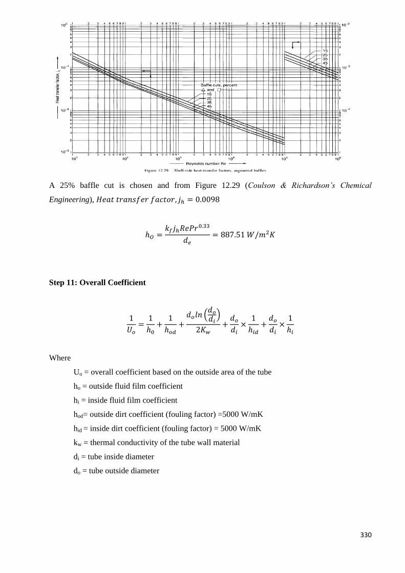
330
A 25% baffle cut is chosen and from Figure 12.29 (Coulson & Richardson’s Chemical
Engineering), 𝐻𝑒𝑎𝑡 𝑡𝑟𝑎𝑛𝑠𝑓𝑒𝑟 𝑓𝑎𝑐𝑡𝑜𝑟, 𝑗ℎ = 0.0098
ℎ𝑂 =𝑘𝑓𝑗ℎ𝑅𝑒𝑃𝑟0.33
𝑑𝑒= 887.51 𝑊/𝑚2𝐾
Step 11: Overall Coefficient
1
𝑈𝑜=
1
ℎ0+
1
ℎ𝑜𝑑+
𝑑𝑜𝑙𝑛 (𝑑𝑜
𝑑𝑖)
2𝐾𝑤+
𝑑𝑜
𝑑𝑖×
1
ℎ𝑖𝑑+
𝑑𝑜
𝑑𝑖×
1
ℎ𝑖
Where
Uo = overall coefficient based on the outside area of the tube
ho = outside fluid film coefficient
hi = inside fluid film coefficient
hod= outside dirt coefficient (fouling factor) =5000 W/mK
hid = inside dirt coefficient (fouling factor) = 5000 W/mK
kw = thermal conductivity of the tube wall material
di = tube inside diameter
do = tube outside diameter
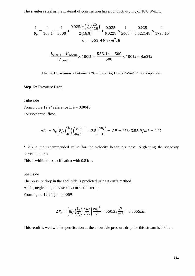
331
The stainless steel as the material of construction has a conductivity Kw of 18.8 W/mK.
1
𝑈𝑜=
1
103.1+
1
5000+
0.025𝑙𝑛 (0.0250.0228)
2(18.8)+
0.025
0.0228×
1
5000+
0.025
0.022148×
1
1735.15
𝑈𝑜 = 𝟓𝟓𝟑. 𝟒𝟒 𝒘/𝒎𝟐. 𝑲
𝑈𝑜,𝑐𝑎𝑙𝑐 − 𝑈𝑜,𝑎𝑠𝑠𝑢
𝑈𝑜,𝑎𝑠𝑠𝑢× 100% =
𝟓𝟓𝟑. 𝟒𝟒 − 500
500× 100% = 0.62%
Hence, Uo assume is between 0% – 30%. So, Uo= 75W/m2 K is acceptable.
Step 12: Pressure Drop
Tube side
From figure 12.24 reference 1, jf = 0.0045
For isothermal flow,
∆𝑃𝑇 = 𝑁𝑝 [8𝑗𝑓 (𝐿
𝑑𝑖) (
𝜇
𝜇𝑤)−𝑚
+ 2.5]𝜌𝑢𝑡
2
2= ∆𝑃 = 27643.55 𝑁/𝑚2 = 0.27
* 2.5 is the recommended value for the velocity heads per pass. Neglecting the viscosity
correction term
This is within the specification with 0.8 bar.
Shell side
The pressure drop in the shell side is predicted using Kern‟s method.
Again, neglecting the viscosity correction term;
From figure 12.24, jf = 0.0059
∆𝑃𝑆 = [8𝑗𝑓 (𝐷𝑠
𝑑𝑒) (
𝐿
𝑙𝐵)]
𝜌𝑢𝑠2
2= 550.33
𝑁
𝑚2= 0.0055𝑏𝑎𝑟
This result is well within specification as the allowable pressure drop for this stream is 0.8 bar.
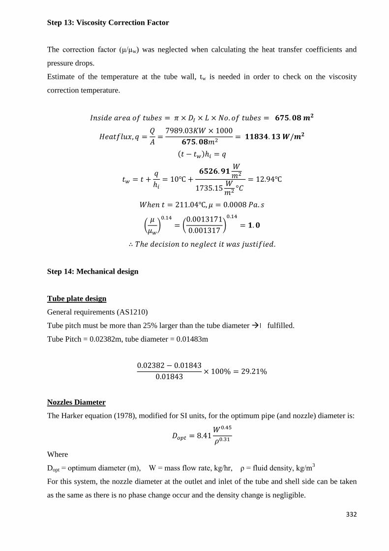
332
Step 13: Viscosity Correction Factor
The correction factor (μ/μw) was neglected when calculating the heat transfer coefficients and
pressure drops.
Estimate of the temperature at the tube wall, tw is needed in order to check on the viscosity
correction temperature.
𝐼𝑛𝑠𝑖𝑑𝑒 𝑎𝑟𝑒𝑎 𝑜𝑓 𝑡𝑢𝑏𝑒𝑠 = 𝜋 × 𝐷𝐼 × 𝐿 × 𝑁𝑜. 𝑜𝑓 𝑡𝑢𝑏𝑒𝑠 = 𝟔𝟕𝟓. 𝟎𝟖 𝒎𝟐
𝐻𝑒𝑎𝑡𝑓𝑙𝑢𝑥, 𝑞 =𝑄
𝐴=
7989.03𝐾𝑊 × 1000
𝟔𝟕𝟓. 𝟎𝟖𝑚2= 𝟏𝟏𝟖𝟑𝟒. 𝟏𝟑 𝑾/𝒎𝟐
(𝑡 − 𝑡𝑤)ℎ𝑖 = 𝑞
𝑡𝑤 = 𝑡 +𝑞
ℎ𝑖= 10℃ +
𝟔𝟓𝟐𝟔. 𝟗𝟏𝑊𝑚2
1735.15𝑊𝑚2 °𝐶
= 12.94℃
𝑊ℎ𝑒𝑛 𝑡 = 211.04℃, 𝜇 = 0.0008 𝑃𝑎. 𝑠
(𝜇
𝜇𝑤)0.14
= (0.0013171
0.001317)0.14
= 𝟏. 𝟎
∴ 𝑇ℎ𝑒 𝑑𝑒𝑐𝑖𝑠𝑖𝑜𝑛 𝑡𝑜 𝑛𝑒𝑔𝑙𝑒𝑐𝑡 𝑖𝑡 𝑤𝑎𝑠 𝑗𝑢𝑠𝑡𝑖𝑓𝑖𝑒𝑑.
Step 14: Mechanical design
Tube plate design
General requirements (AS1210)
Tube pitch must be more than 25% larger than the tube diameter fulfilled.
Tube Pitch = 0.02382m, tube diameter = 0.01483m
0.02382 − 0.01843
0.01843× 100% = 29.21%
Nozzles Diameter
The Harker equation (1978), modified for SI units, for the optimum pipe (and nozzle) diameter is:
𝐷𝑜𝑝𝑡 = 8.41𝑊0.45
𝜌0.31
Where
Dopt = optimum diameter (m), W = mass flow rate, kg/hr, ρ = fluid density, kg/m3
For this system, the nozzle diameter at the outlet and inlet of the tube and shell side can be taken
as the same as there is no phase change occur and the density change is negligible.
333
Tube
𝐷𝑜𝑝𝑡 = 8.41(95.53)0.45
(1100.8)0.31 = 0.30 𝑚
Therefore, a 0.30 m diameter nozzle was specified for the tube-side inlet
Shell
Nozzle
𝐷𝑜𝑝𝑡 = 8.41(6.5142)0.45
(792.97)0.31 = 0.10𝑚
A nozzle size of 0.10 m diameter is selected for the inlet and outlet at the shell side of the
exchanger.
Support design
For a horizontal vessel, it is usually mounted on two saddles supports.
Foundation: Concrete slab
Insulation
We were using fiber glass for insulated the heat exchanger.
K fiber glass= 0.04 W/m.K
r = 𝐾
ℎ𝑜=
0.04
103.1 =3.9 × 10⁻⁴𝑚=0.39 mm
334
Summary
Split ring, floating head, one shell pass, and 6 tube passes.
Stainless Steel tubes, 5 m long,0.01905m o.d., 0.01843m i.d., triangular pitch=0.02381 mm.
Heat transfer area 697.79 m2 (based on outside diameter).
Shell i.d. 1.276m, baffle spacing 0.2552m, 25% cut.
Tube-side coefficient 4027.36 W/m2.K, clean.
Shell-side coefficient 887.51 W/ m2. K, clean.
Overall coefficient, estimated 550 W/m2. K.
Overall coefficient, calculated 553.4 W/m2. K.
Dirt/fouling factors:
Tube side (process fluid) 5000 (W/m2. K)
-1.
Shell side (steam) 5000 (W/m2.
K)-1
.
Pressure drops:
Tube side, estimated 0.276 bar; allowable 0.8 bar.
Shell side, estimated 0.0055 bar; allowable 0.8 bar.
Nozzle diameter for tube and shell side is 0.30 m and 0.10 m, respectively.
335
E-106 Reboiler
The Reboiler E-106 is used to vaporise the process mixture at 25 bar from T=90OC to T= 100
OC.
The steam used to heat up the mixture enters at T=250OC and leaves at T=150
OC at 26 bar.
Reference:
1. The calculation here follow the example paged 623-630 from Coulson and Richardson’s,
“Chemical Engineering, Volume 6”, 4th
edition.
2. FELDER, R. M. R., R. W. 2005. Elementary Principles of Chemical Processes, John
Wiley & Sons, Inc.
3. PERRY, R. H. A. G., DON W. 1984. Perry's Chemical Engineers' Handbook McGraw-
Hill.
4. SINNOTT, R. K. 2003. Chemical Engineering, Butterworth-Heineman
Design parameters:
Outside diameter (OD) and inside diameter (ID) for tubes Number of tubes
Number of tube passes and shell passes
Diameter of tube bundle, DB
Diameter of shell, DS
Baffle spacing, lb
Overall heat transfer coefficient
Tube side pressure drop, ΔPt
Shell side pressure drop, ΔPs
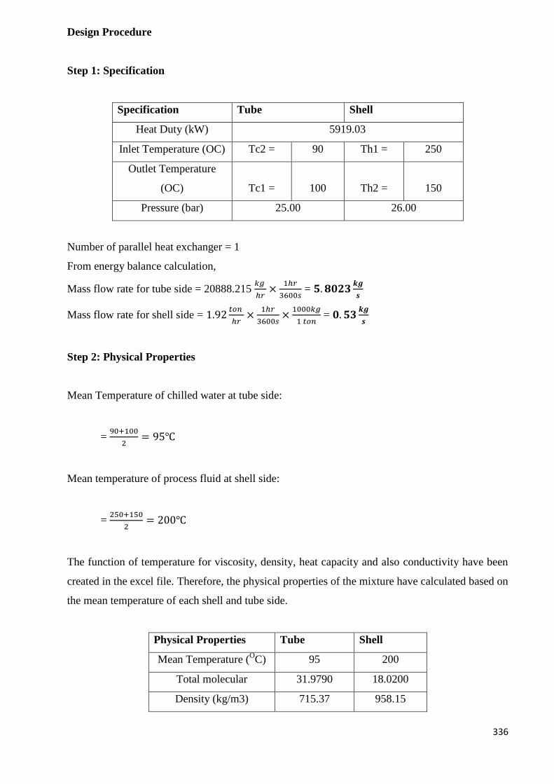
336
Design Procedure
Step 1: Specification
Specification Tube Shell
Heat Duty (kW) 5919.03
Inlet Temperature (OC) Tc2 = 90 Th1 = 250
Outlet Temperature
(OC) Tc1 = 100 Th2 = 150
Pressure (bar) 25.00 26.00
Number of parallel heat exchanger = 1
From energy balance calculation,
Mass flow rate for tube side = 20888.215 𝑘𝑔
ℎ𝑟×
1ℎ𝑟
3600𝑠 = 𝟓. 𝟖𝟎𝟐𝟑
𝒌𝒈
𝒔
Mass flow rate for shell side = 1.92𝑡𝑜𝑛
ℎ𝑟×
1ℎ𝑟
3600𝑠×
1000𝑘𝑔
1 𝑡𝑜𝑛 = 𝟎. 𝟓𝟑
𝒌𝒈
𝒔
Step 2: Physical Properties
Mean Temperature of chilled water at tube side:
= 90+100
2= 95℃
Mean temperature of process fluid at shell side:
= 250+150
2= 200℃
The function of temperature for viscosity, density, heat capacity and also conductivity have been
created in the excel file. Therefore, the physical properties of the mixture have calculated based on
the mean temperature of each shell and tube side.
Physical Properties Tube Shell
Mean Temperature (OC) 95 200
Total molecular 31.9790 18.0200
Density (kg/m3) 715.37 958.15
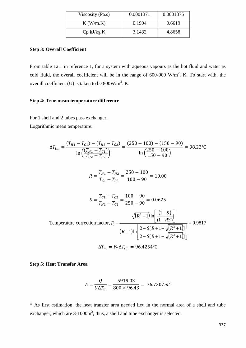
337
Viscosity (Pa.s) 0.0001371 0.0001375
K (W/m.K) 0.1904 0.6619
Cp kJ/kg.K 3.1432 4.8658
Step 3: Overall Coefficient
From table 12.1 in reference 1, for a system with aqueous vapours as the hot fluid and water as
cold fluid, the overall coefficient will be in the range of 600-900 W/m2. K. To start with, the
overall coefficient (U) is taken to be 800W/m2. K.
Step 4: True mean temperature difference
For 1 shell and 2 tubes pass exchanger,
Logarithmic mean temperature:
∆𝑇𝑙𝑚 =(𝑇𝐻1 − 𝑇𝐶1) − (𝑇𝐻2 − 𝑇𝐶2)
ln ((𝑇𝐻1 − 𝑇𝐶1)𝑇𝐻2 − 𝑇𝐶2
)=
(250 − 100) − (150 − 90)
ln (250 − 100150 − 90
)= 98.22℃
𝑅 =𝑇𝐻1 − 𝑇𝐻2
𝑇𝐶1 − 𝑇𝐶2=
250 − 100
100 − 90= 10.00
𝑆 =𝑇𝐶1 − 𝑇𝐶2
𝑇𝐻1 − 𝑇𝐶2=
100 − 90
250 − 90= 0.0625
Temperature correction factor,
]11[2
]11[2ln1
)1(
1ln1
2
2
2
RRS
RRSR
RS
SR
Ft= 0.9817
∆𝑇𝑚 = 𝐹𝑇∆𝑇𝑙𝑚 = 96.4254℃
Step 5: Heat Transfer Area
𝐴 =𝑄
𝑈∆𝑇𝑚=
5919.03
800 × 96.43= 76.7307𝑚2
* As first estimation, the heat transfer area needed lied in the normal area of a shell and tube
exchanger, which are 3-1000m2, thus, a shell and tube exchanger is selected.
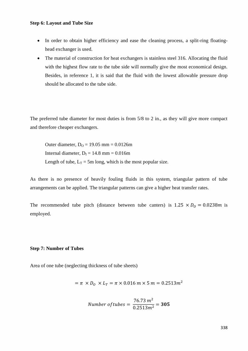
338
Step 6: Layout and Tube Size
In order to obtain higher efficiency and ease the cleaning process, a split-ring floating-
head exchanger is used.
The material of construction for heat exchangers is stainless steel 316. Allocating the fluid
with the highest flow rate to the tube side will normally give the most economical design.
Besides, in reference 1, it is said that the fluid with the lowest allowable pressure drop
should be allocated to the tube side.
The preferred tube diameter for most duties is from 5/8 to 2 in., as they will give more compact
and therefore cheaper exchangers.
Outer diameter, DO = 19.05 mm = 0.0126m
Internal diameter, DI = 14.8 mm = 0.016m
Length of tube, LT = 5m long, which is the most popular size.
As there is no presence of heavily fouling fluids in this system, triangular pattern of tube
arrangements can be applied. The triangular patterns can give a higher heat transfer rates.
The recommended tube pitch (distance between tube canters) is 1.25 × 𝐷𝑂 = 0.0238𝑚 is
employed.
Step 7: Number of Tubes
Area of one tube (neglecting thickness of tube sheets)
= 𝜋 × 𝐷𝑂 × 𝐿𝑇 = 𝜋 × 0.016 𝑚 × 5 𝑚 = 0.2513𝑚2
𝑁𝑢𝑚𝑏𝑒𝑟 𝑜𝑓𝑡𝑢𝑏𝑒𝑠 = 76.73 𝑚2
0.2513𝑚2= 𝟑𝟎𝟓
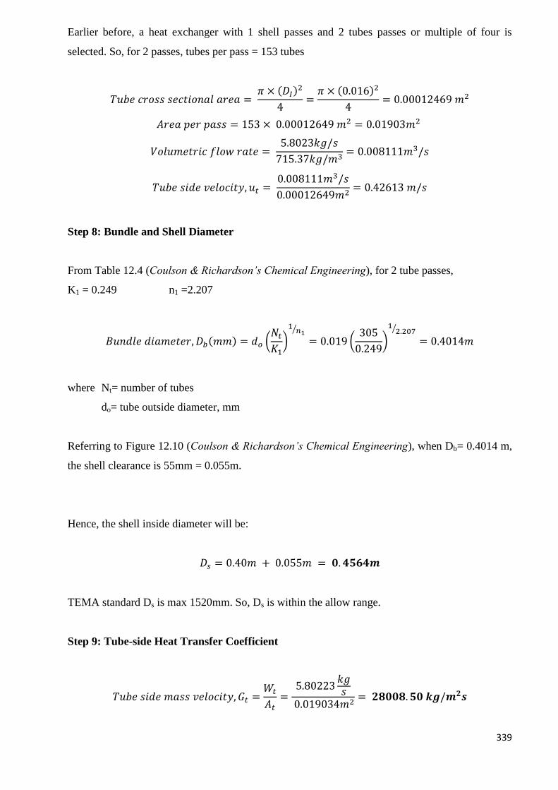
339
Earlier before, a heat exchanger with 1 shell passes and 2 tubes passes or multiple of four is
selected. So, for 2 passes, tubes per pass = 153 tubes
𝑇𝑢𝑏𝑒 𝑐𝑟𝑜𝑠𝑠 𝑠𝑒𝑐𝑡𝑖𝑜𝑛𝑎𝑙 𝑎𝑟𝑒𝑎 = 𝜋 × (𝐷𝐼)
2
4=
𝜋 × (0.016)2
4= 0.00012469 𝑚2
𝐴𝑟𝑒𝑎 𝑝𝑒𝑟 𝑝𝑎𝑠𝑠 = 153 × 0.00012649 𝑚2 = 0.01903𝑚2
𝑉𝑜𝑙𝑢𝑚𝑒𝑡𝑟𝑖𝑐 𝑓𝑙𝑜𝑤 𝑟𝑎𝑡𝑒 = 5.8023𝑘𝑔/𝑠
715.37𝑘𝑔/𝑚3= 0.008111𝑚3/𝑠
𝑇𝑢𝑏𝑒 𝑠𝑖𝑑𝑒 𝑣𝑒𝑙𝑜𝑐𝑖𝑡𝑦, 𝑢𝑡 = 0.008111𝑚3/𝑠
0.00012649𝑚2= 0.42613 𝑚/𝑠
Step 8: Bundle and Shell Diameter
From Table 12.4 (Coulson & Richardson’s Chemical Engineering), for 2 tube passes,
K1 = 0.249 n1 =2.207
𝐵𝑢𝑛𝑑𝑙𝑒 𝑑𝑖𝑎𝑚𝑒𝑡𝑒𝑟, 𝐷𝑏(𝑚𝑚) = 𝑑𝑜 (𝑁𝑡
𝐾1)
1𝑛1
⁄
= 0.019 (305
0.249)
12.207⁄
= 0.4014𝑚
where Nt= number of tubes
do= tube outside diameter, mm
Referring to Figure 12.10 (Coulson & Richardson’s Chemical Engineering), when Db= 0.4014 m,
the shell clearance is 55mm = 0.055m.
Hence, the shell inside diameter will be:
𝐷𝑠 = 0.40𝑚 + 0.055𝑚 = 𝟎. 𝟒𝟓𝟔𝟒𝒎
TEMA standard Ds is max 1520mm. So, Ds is within the allow range.
Step 9: Tube-side Heat Transfer Coefficient
𝑇𝑢𝑏𝑒 𝑠𝑖𝑑𝑒 𝑚𝑎𝑠𝑠 𝑣𝑒𝑙𝑜𝑐𝑖𝑡𝑦, 𝐺𝑡 =𝑊𝑡
𝐴𝑡=
5.80223𝑘𝑔𝑠
0.019034𝑚2= 𝟐𝟖𝟎𝟎𝟖. 𝟓𝟎 𝒌𝒈/𝒎𝟐𝒔
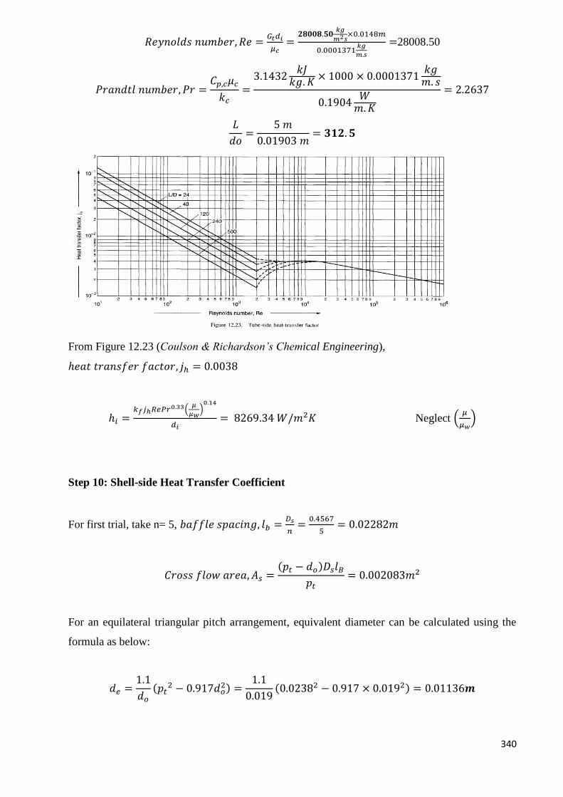
340
𝑅𝑒𝑦𝑛𝑜𝑙𝑑𝑠 𝑛𝑢𝑚𝑏𝑒𝑟, 𝑅𝑒 =𝐺𝑡𝑑𝑖
𝜇𝑐=
𝟐𝟖𝟎𝟎𝟖.𝟓𝟎𝑘𝑔
𝑚2𝑠×0.0148𝑚
0.0001371𝑘𝑔
𝑚.𝑠
=28008.50
𝑃𝑟𝑎𝑛𝑑𝑡𝑙 𝑛𝑢𝑚𝑏𝑒𝑟, 𝑃𝑟 =𝐶𝑝,𝑐𝜇𝑐
𝑘𝑐=
3.1432𝑘𝐽
𝑘𝑔. 𝐾× 1000 × 0.0001371
𝑘𝑔𝑚. 𝑠
0.1904𝑊
𝑚.𝐾
= 2.2637
𝐿
𝑑𝑜=
5 𝑚
0.01903 𝑚= 𝟑𝟏𝟐. 𝟓
From Figure 12.23 (Coulson & Richardson’s Chemical Engineering),
ℎ𝑒𝑎𝑡 𝑡𝑟𝑎𝑛𝑠𝑓𝑒𝑟 𝑓𝑎𝑐𝑡𝑜𝑟, 𝑗ℎ = 0.0038
ℎ𝑖 =𝑘𝑓𝑗ℎ𝑅𝑒𝑃𝑟0.33(
𝜇
𝜇𝑤)0.14
𝑑𝑖= 8269.34 𝑊/𝑚2𝐾 Neglect (
𝜇
𝜇𝑤)
Step 10: Shell-side Heat Transfer Coefficient
For first trial, take n= 5, 𝑏𝑎𝑓𝑓𝑙𝑒 𝑠𝑝𝑎𝑐𝑖𝑛𝑔, 𝑙𝑏 =𝐷𝑠
𝑛=
0.4567
5= 0.02282𝑚
𝐶𝑟𝑜𝑠𝑠 𝑓𝑙𝑜𝑤 𝑎𝑟𝑒𝑎, 𝐴𝑠 =(𝑝𝑡 − 𝑑𝑜)𝐷𝑠𝑙𝐵
𝑝𝑡= 0.002083𝑚2
For an equilateral triangular pitch arrangement, equivalent diameter can be calculated using the
formula as below:
𝑑𝑒 =1.1
𝑑𝑜
(𝑝𝑡2 − 0.917𝑑𝑜
2) =1.1
0.019(0.02382 − 0.917 × 0.0192) = 0.01136𝒎
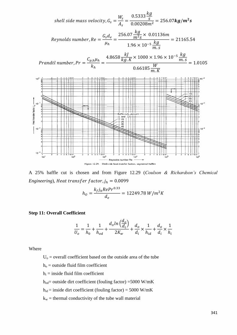
341
𝑠ℎ𝑒𝑙𝑙 𝑠𝑖𝑑𝑒 𝑚𝑎𝑠𝑠 𝑣𝑒𝑙𝑜𝑐𝑖𝑡𝑦, 𝐺𝑠 =𝑊𝑠
𝐴𝑠=
0.5333𝑘𝑔𝑠
0.00208𝑚2= 256.07𝒌𝒈/𝒎𝟐𝒔
𝑅𝑒𝑦𝑛𝑜𝑙𝑑𝑠 𝑛𝑢𝑚𝑏𝑒𝑟, 𝑅𝑒 =𝐺𝑠𝑑𝑒
𝜇ℎ=
256.07𝑘𝑔𝑚2𝑠
× 0.01136𝑚
1.96 × 10⁻⁵ 𝑘𝑔𝑚. 𝑠
= 21165.54
𝑃𝑟𝑎𝑛𝑑𝑡𝑙 𝑛𝑢𝑚𝑏𝑒𝑟, 𝑃𝑟 =𝐶𝑝,ℎ𝜇ℎ
𝑘ℎ=
4.8658𝑘𝐽
𝑘𝑔. 𝐾× 1000 × 1.96 × 10−5 𝑘𝑔
𝑚. 𝑠
0.66185𝑊
𝑚.𝐾
= 1.0105
A 25% baffle cut is chosen and from Figure 12.29 (Coulson & Richardson’s Chemical
Engineering), 𝐻𝑒𝑎𝑡 𝑡𝑟𝑎𝑛𝑠𝑓𝑒𝑟 𝑓𝑎𝑐𝑡𝑜𝑟, 𝑗ℎ = 0.0099
ℎ𝑂 =𝑘𝑓𝑗ℎ𝑅𝑒𝑃𝑟0.33
𝑑𝑒= 12249.78 𝑊/𝑚2𝐾
Step 11: Overall Coefficient
1
𝑈𝑜=
1
ℎ0+
1
ℎ𝑜𝑑+
𝑑𝑜𝑙𝑛 (𝑑𝑜
𝑑𝑖)
2𝐾𝑤+
𝑑𝑜
𝑑𝑖×
1
ℎ𝑖𝑑+
𝑑𝑜
𝑑𝑖×
1
ℎ𝑖
Where
Uo = overall coefficient based on the outside area of the tube
ho = outside fluid film coefficient
hi = inside fluid film coefficient
hod= outside dirt coefficient (fouling factor) =5000 W/mK
hid = inside dirt coefficient (fouling factor) = 5000 W/mK
kw = thermal conductivity of the tube wall material
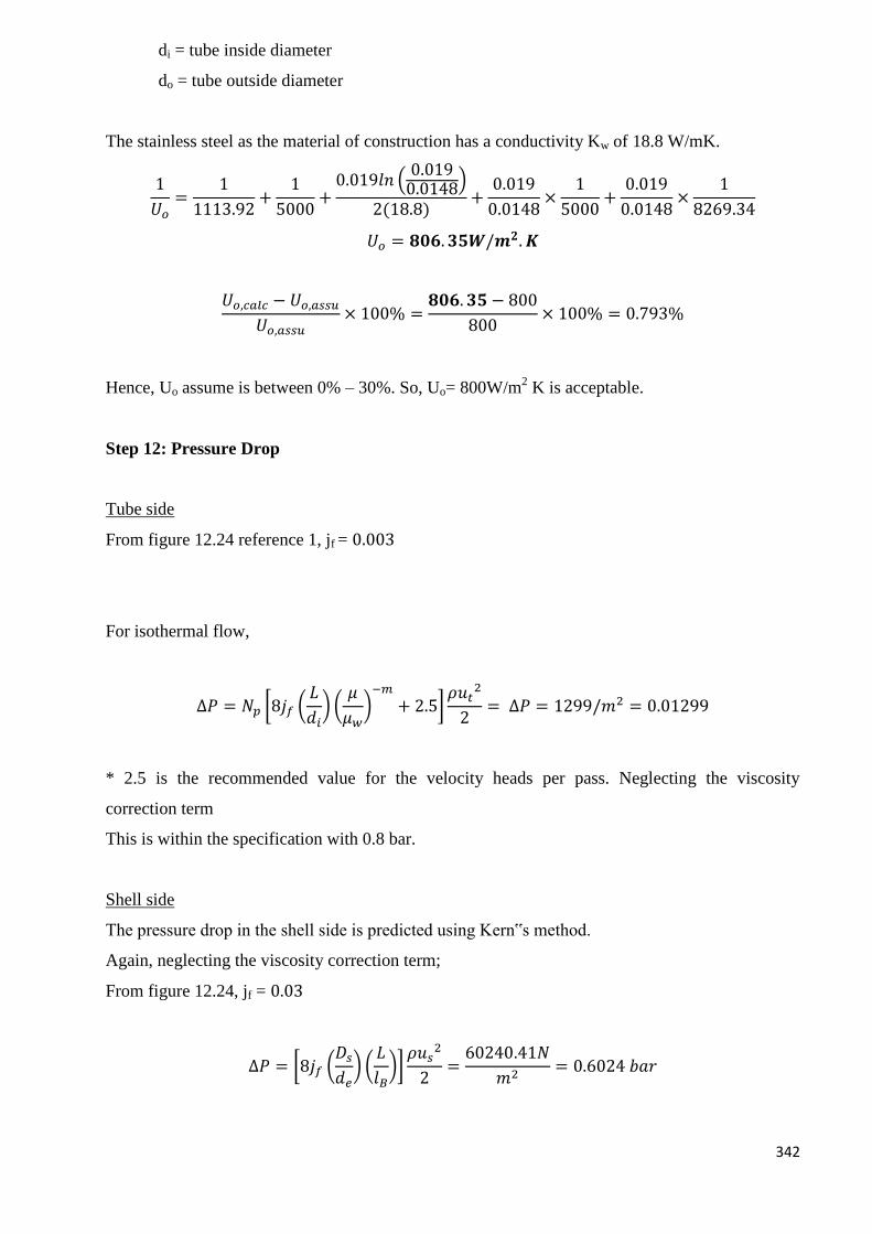
342
di = tube inside diameter
do = tube outside diameter
The stainless steel as the material of construction has a conductivity Kw of 18.8 W/mK.
1
𝑈𝑜=
1
1113.92+
1
5000+
0.019𝑙𝑛 (0.0190.0148)
2(18.8)+
0.019
0.0148×
1
5000+
0.019
0.0148×
1
8269.34
𝑈𝑜 = 𝟖𝟎𝟔. 𝟑𝟓𝑾/𝒎𝟐. 𝑲
𝑈𝑜,𝑐𝑎𝑙𝑐 − 𝑈𝑜,𝑎𝑠𝑠𝑢
𝑈𝑜,𝑎𝑠𝑠𝑢× 100% =
𝟖𝟎𝟔. 𝟑𝟓 − 800
800× 100% = 0.793%
Hence, Uo assume is between 0% – 30%. So, Uo= 800W/m2 K is acceptable.
Step 12: Pressure Drop
Tube side
From figure 12.24 reference 1, jf = 0.003
For isothermal flow,
∆𝑃 = 𝑁𝑝 [8𝑗𝑓 (𝐿
𝑑𝑖) (
𝜇
𝜇𝑤)−𝑚
+ 2.5]𝜌𝑢𝑡
2
2= ∆𝑃 = 1299/𝑚2 = 0.01299
* 2.5 is the recommended value for the velocity heads per pass. Neglecting the viscosity
correction term
This is within the specification with 0.8 bar.
Shell side
The pressure drop in the shell side is predicted using Kern‟s method.
Again, neglecting the viscosity correction term;
From figure 12.24, jf = 0.03
∆𝑃 = [8𝑗𝑓 (𝐷𝑠
𝑑𝑒) (
𝐿
𝑙𝐵)]
𝜌𝑢𝑠2
2=
60240.41𝑁
𝑚2= 0.6024 𝑏𝑎𝑟
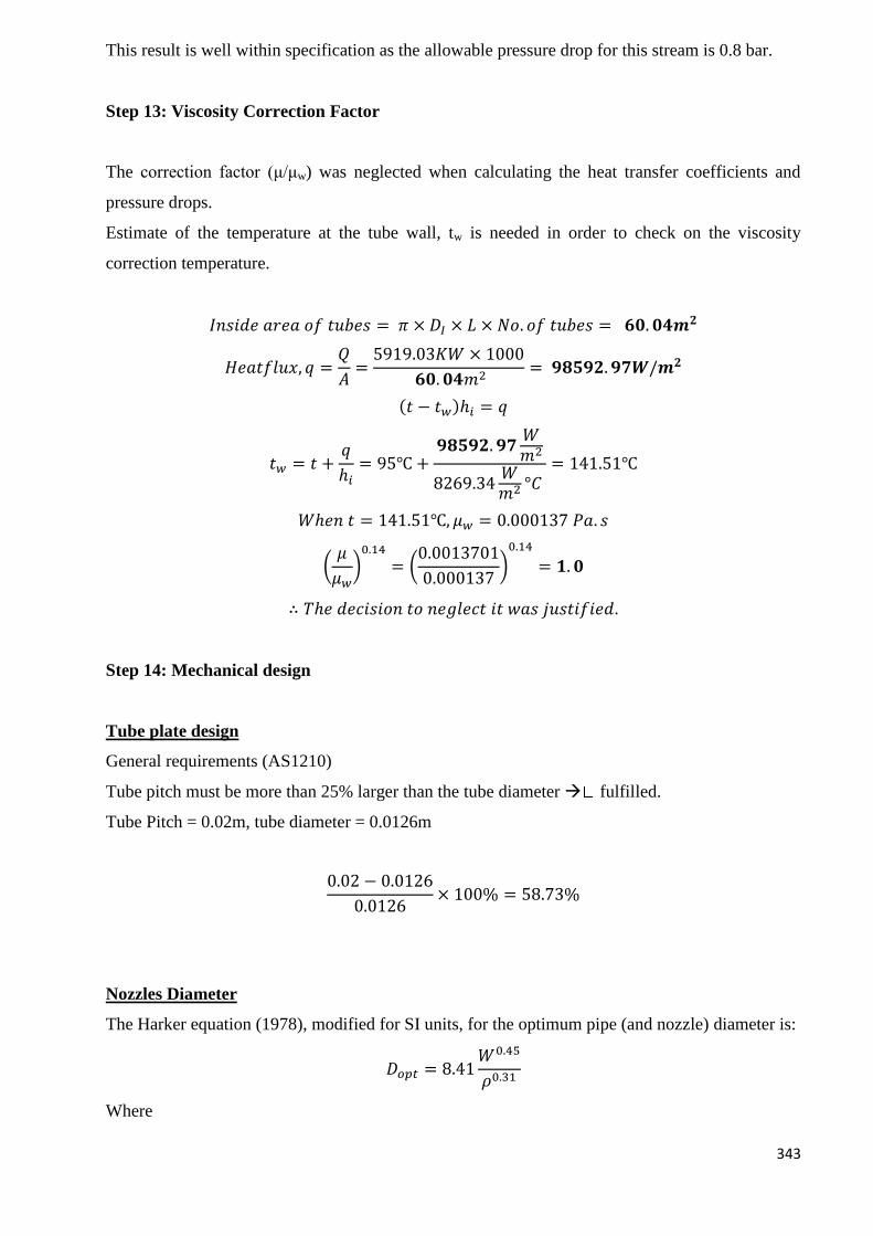
343
This result is well within specification as the allowable pressure drop for this stream is 0.8 bar.
Step 13: Viscosity Correction Factor
The correction factor (μ/μw) was neglected when calculating the heat transfer coefficients and
pressure drops.
Estimate of the temperature at the tube wall, tw is needed in order to check on the viscosity
correction temperature.
𝐼𝑛𝑠𝑖𝑑𝑒 𝑎𝑟𝑒𝑎 𝑜𝑓 𝑡𝑢𝑏𝑒𝑠 = 𝜋 × 𝐷𝐼 × 𝐿 × 𝑁𝑜. 𝑜𝑓 𝑡𝑢𝑏𝑒𝑠 = 𝟔𝟎. 𝟎𝟒𝒎𝟐
𝐻𝑒𝑎𝑡𝑓𝑙𝑢𝑥, 𝑞 =𝑄
𝐴=
5919.03𝐾𝑊 × 1000
𝟔𝟎. 𝟎𝟒𝑚2= 𝟗𝟖𝟓𝟗𝟐. 𝟗𝟕𝑾/𝒎𝟐
(𝑡 − 𝑡𝑤)ℎ𝑖 = 𝑞
𝑡𝑤 = 𝑡 +𝑞
ℎ𝑖= 95℃ +
𝟗𝟖𝟓𝟗𝟐. 𝟗𝟕𝑊𝑚2
8269.34𝑊𝑚2 °𝐶
= 141.51℃
𝑊ℎ𝑒𝑛 𝑡 = 141.51℃, 𝜇𝑤 = 0.000137 𝑃𝑎. 𝑠
(𝜇
𝜇𝑤)0.14
= (0.0013701
0.000137)0.14
= 𝟏. 𝟎
∴ 𝑇ℎ𝑒 𝑑𝑒𝑐𝑖𝑠𝑖𝑜𝑛 𝑡𝑜 𝑛𝑒𝑔𝑙𝑒𝑐𝑡 𝑖𝑡 𝑤𝑎𝑠 𝑗𝑢𝑠𝑡𝑖𝑓𝑖𝑒𝑑.
Step 14: Mechanical design
Tube plate design
General requirements (AS1210)
Tube pitch must be more than 25% larger than the tube diameter fulfilled.
Tube Pitch = 0.02m, tube diameter = 0.0126m
0.02 − 0.0126
0.0126× 100% = 58.73%
Nozzles Diameter
The Harker equation (1978), modified for SI units, for the optimum pipe (and nozzle) diameter is:
𝐷𝑜𝑝𝑡 = 8.41𝑊0.45
𝜌0.31
Where
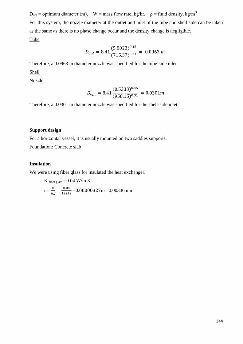
344
Dopt = optimum diameter (m), W = mass flow rate, kg/hr, ρ = fluid density, kg/m3
For this system, the nozzle diameter at the outlet and inlet of the tube and shell side can be taken
as the same as there is no phase change occur and the density change is negligible.
Tube
𝐷𝑜𝑝𝑡 = 8.41(5.8023)0.45
(715.37)0.31 = 0.0963 𝑚
Therefore, a 0.0963 m diameter nozzle was specified for the tube-side inlet
Shell
Nozzle
𝐷𝑜𝑝𝑡 = 8.41(0.5333)0.45
(958.15)0.31 = 0.0301𝑚
Therefore, a 0.0301 m diameter nozzle was specified for the shell-side inlet
Support design
For a horizontal vessel, it is usually mounted on two saddles supports.
Foundation: Concrete slab
Insulation
We were using fiber glass for insulated the heat exchanger.
K fiber glass= 0.04 W/m.K
r = 𝐾
ℎ𝑜=
0.04
12249 =0.00000327m =0.00336 mm
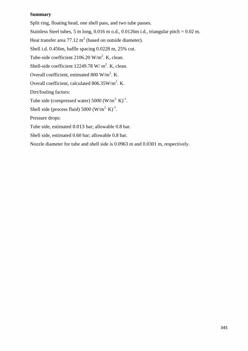
345
Summary
Split ring, floating head, one shell pass, and two tube passes.
Stainless Steel tubes, 5 m long, 0.016 m o.d., 0.0126m i.d., triangular pitch = 0.02 m.
Heat transfer area 77.12 m2 (based on outside diameter).
Shell i.d. 0.456m, baffle spacing 0.0228 m, 25% cut.
Tube-side coefficient 2106.20 W/m2. K, clean.
Shell-side coefficient 12249.78 W/ m2. K, clean.
Overall coefficient, estimated 800 W/m2. K.
Overall coefficient, calculated 806.35W/m2. K.
Dirt/fouling factors:
Tube side (compressed water) 5000 (W/m2.
K)-1
.
Shell side (process fluid) 5000 (W/m2. K)
-1.
Pressure drops:
Tube side, estimated 0.013 bar; allowable 0.8 bar.
Shell side, estimated 0.60 bar; allowable 0.8 bar.
Nozzle diameter for tube and shell side is 0.0963 m and 0.0301 m, respectively.
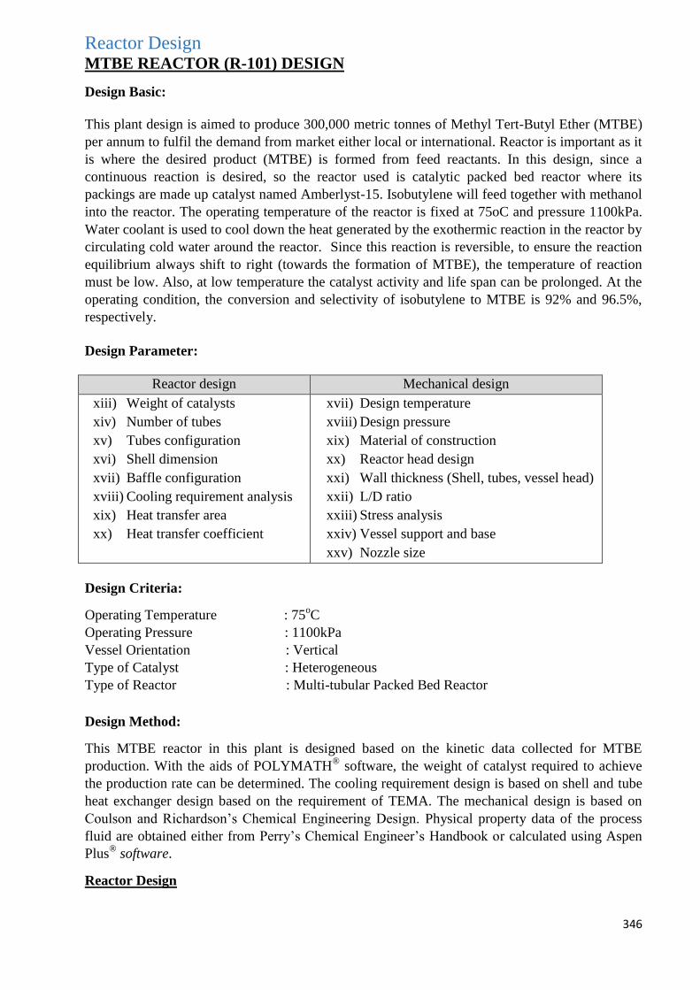
346
Reactor Design MTBE REACTOR (R-101) DESIGN
Design Basic:
This plant design is aimed to produce 300,000 metric tonnes of Methyl Tert-Butyl Ether (MTBE)
per annum to fulfil the demand from market either local or international. Reactor is important as it
is where the desired product (MTBE) is formed from feed reactants. In this design, since a
continuous reaction is desired, so the reactor used is catalytic packed bed reactor where its
packings are made up catalyst named Amberlyst-15. Isobutylene will feed together with methanol
into the reactor. The operating temperature of the reactor is fixed at 75oC and pressure 1100kPa.
Water coolant is used to cool down the heat generated by the exothermic reaction in the reactor by
circulating cold water around the reactor. Since this reaction is reversible, to ensure the reaction
equilibrium always shift to right (towards the formation of MTBE), the temperature of reaction
must be low. Also, at low temperature the catalyst activity and life span can be prolonged. At the
operating condition, the conversion and selectivity of isobutylene to MTBE is 92% and 96.5%,
respectively.
Design Parameter:
Reactor design Mechanical design
xiii) Weight of catalysts
xiv) Number of tubes
xv) Tubes configuration
xvi) Shell dimension
xvii) Baffle configuration
xviii) Cooling requirement analysis
xix) Heat transfer area
xx) Heat transfer coefficient
xvii) Design temperature
xviii) Design pressure
xix) Material of construction
xx) Reactor head design
xxi) Wall thickness (Shell, tubes, vessel head)
xxii) L/D ratio
xxiii) Stress analysis
xxiv) Vessel support and base
xxv) Nozzle size
Design Criteria:
Operating Temperature : 75oC
Operating Pressure : 1100kPa
Vessel Orientation : Vertical
Type of Catalyst : Heterogeneous
Type of Reactor : Multi-tubular Packed Bed Reactor
Design Method:
This MTBE reactor in this plant is designed based on the kinetic data collected for MTBE
production. With the aids of POLYMATH®
software, the weight of catalyst required to achieve
the production rate can be determined. The cooling requirement design is based on shell and tube
heat exchanger design based on the requirement of TEMA. The mechanical design is based on
Coulson and Richardson’s Chemical Engineering Design. Physical property data of the process
fluid are obtained either from Perry’s Chemical Engineer’s Handbook or calculated using Aspen
Plus®
software.
Reactor Design
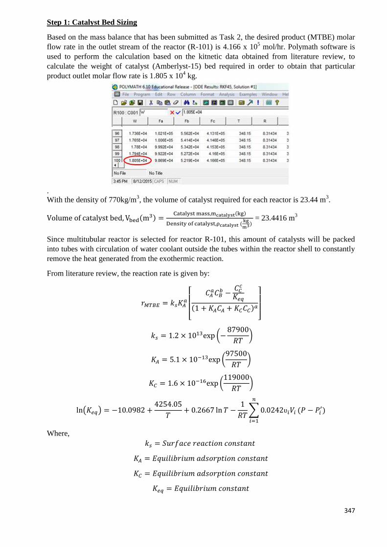
347
Step 1: Catalyst Bed Sizing
Based on the mass balance that has been submitted as Task 2, the desired product (MTBE) molar
flow rate in the outlet stream of the reactor (R-101) is 4.166 x 10⁵ mol/hr. Polymath software is
used to perform the calculation based on the kitnetic data obtained from literature review, to
calculate the weight of catalyst (Amberlyst-15) bed required in order to obtain that particular
product outlet molar flow rate is 1.805 x 10⁴ kg.
.
With the density of 770kg/m3, the volume of catalyst required for each reactor is 23.44 m
3.
Volume of catalyst bed, Vbed(m3) =
Catalyst mass,mcatalyst(kg)
Density of catalyst,ρcatalyst (kg
m3) = 23.4416 m
3
Since multitubular reactor is selected for reactor R-101, this amount of catalysts will be packed
into tubes with circulation of water coolant outside the tubes within the reactor shell to constantly
remove the heat generated from the exothermic reaction.
From literature review, the reaction rate is given by:
𝑟𝑀𝑇𝐵𝐸 = 𝑘𝑠𝐾𝐴𝑎
[ 𝐶𝐴
𝑎𝐶𝐵𝑏 −
𝐶𝐶𝑐
𝐾𝑒𝑞
(1 + 𝐾𝐴𝐶𝐴 + 𝐾𝐶𝐶𝐶)𝑎
]
𝑘𝑠 = 1.2 × 10¹³exp (−87900
𝑅𝑇)
𝐾𝐴 = 5.1 × 10⁻¹³exp (97500
𝑅𝑇)
𝐾𝐶 = 1.6 × 10⁻¹⁶exp (119000
𝑅𝑇)
ln(𝐾𝑒𝑞) = −10.0982 +4254.05
𝑇+ 0.2667 ln 𝑇 −
1
𝑅𝑇∑0.0242ʋ𝑖𝑉𝑖
𝑛
𝑖=1
(𝑃 − 𝑃𝑖′)
Where,
𝑘𝑠 = 𝑆𝑢𝑟𝑓𝑎𝑐𝑒 𝑟𝑒𝑎𝑐𝑡𝑖𝑜𝑛 𝑐𝑜𝑛𝑠𝑡𝑎𝑛𝑡
𝐾𝐴 = 𝐸𝑞𝑢𝑖𝑙𝑖𝑏𝑟𝑖𝑢𝑚 𝑎𝑑𝑠𝑜𝑟𝑝𝑡𝑖𝑜𝑛 𝑐𝑜𝑛𝑠𝑡𝑎𝑛𝑡
𝐾𝐶 = 𝐸𝑞𝑢𝑖𝑙𝑖𝑏𝑟𝑖𝑢𝑚 𝑎𝑑𝑠𝑜𝑟𝑝𝑡𝑖𝑜𝑛 𝑐𝑜𝑛𝑠𝑡𝑎𝑛𝑡
𝐾𝑒𝑞 = 𝐸𝑞𝑢𝑖𝑙𝑖𝑏𝑟𝑖𝑢𝑚 𝑐𝑜𝑛𝑠𝑡𝑎𝑛𝑡
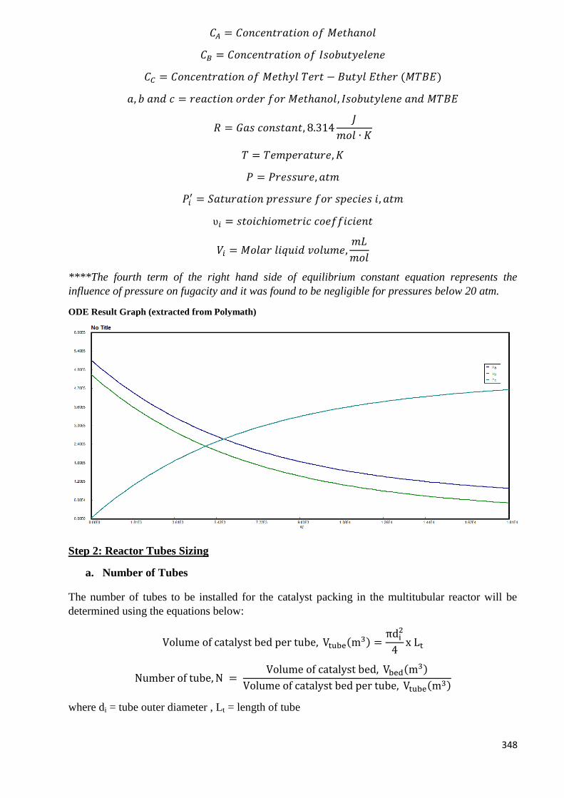
348
𝐶𝐴 = 𝐶𝑜𝑛𝑐𝑒𝑛𝑡𝑟𝑎𝑡𝑖𝑜𝑛 𝑜𝑓 𝑀𝑒𝑡ℎ𝑎𝑛𝑜𝑙
𝐶𝐵 = 𝐶𝑜𝑛𝑐𝑒𝑛𝑡𝑟𝑎𝑡𝑖𝑜𝑛 𝑜𝑓 𝐼𝑠𝑜𝑏𝑢𝑡𝑦𝑒𝑙𝑒𝑛𝑒
𝐶𝐶 = 𝐶𝑜𝑛𝑐𝑒𝑛𝑡𝑟𝑎𝑡𝑖𝑜𝑛 𝑜𝑓 𝑀𝑒𝑡ℎ𝑦𝑙 𝑇𝑒𝑟𝑡 − 𝐵𝑢𝑡𝑦𝑙 𝐸𝑡ℎ𝑒𝑟 (𝑀𝑇𝐵𝐸)
𝑎, 𝑏 𝑎𝑛𝑑 𝑐 = 𝑟𝑒𝑎𝑐𝑡𝑖𝑜𝑛 𝑜𝑟𝑑𝑒𝑟 𝑓𝑜𝑟 𝑀𝑒𝑡ℎ𝑎𝑛𝑜𝑙, 𝐼𝑠𝑜𝑏𝑢𝑡𝑦𝑙𝑒𝑛𝑒 𝑎𝑛𝑑 𝑀𝑇𝐵𝐸
𝑅 = 𝐺𝑎𝑠 𝑐𝑜𝑛𝑠𝑡𝑎𝑛𝑡, 8.314𝐽
𝑚𝑜𝑙 ∙ 𝐾
𝑇 = 𝑇𝑒𝑚𝑝𝑒𝑟𝑎𝑡𝑢𝑟𝑒, 𝐾
𝑃 = 𝑃𝑟𝑒𝑠𝑠𝑢𝑟𝑒, 𝑎𝑡𝑚
𝑃𝑖′ = 𝑆𝑎𝑡𝑢𝑟𝑎𝑡𝑖𝑜𝑛 𝑝𝑟𝑒𝑠𝑠𝑢𝑟𝑒 𝑓𝑜𝑟 𝑠𝑝𝑒𝑐𝑖𝑒𝑠 𝑖, 𝑎𝑡𝑚
ʋ𝑖 = 𝑠𝑡𝑜𝑖𝑐ℎ𝑖𝑜𝑚𝑒𝑡𝑟𝑖𝑐 𝑐𝑜𝑒𝑓𝑓𝑖𝑐𝑖𝑒𝑛𝑡
𝑉𝑖 = 𝑀𝑜𝑙𝑎𝑟 𝑙𝑖𝑞𝑢𝑖𝑑 𝑣𝑜𝑙𝑢𝑚𝑒,𝑚𝐿
𝑚𝑜𝑙
****The fourth term of the right hand side of equilibrium constant equation represents the
influence of pressure on fugacity and it was found to be negligible for pressures below 20 atm.
ODE Result Graph (extracted from Polymath)
Step 2: Reactor Tubes Sizing
a. Number of Tubes
The number of tubes to be installed for the catalyst packing in the multitubular reactor will be
determined using the equations below:
Volume of catalyst bed per tube, Vtube(m3) =
πdi2
4x Lt
Number of tube, N = Volume of catalyst bed, Vbed(m
3)
Volume of catalyst bed per tube, Vtube(m3)
where di = tube outer diameter , Lt = length of tube
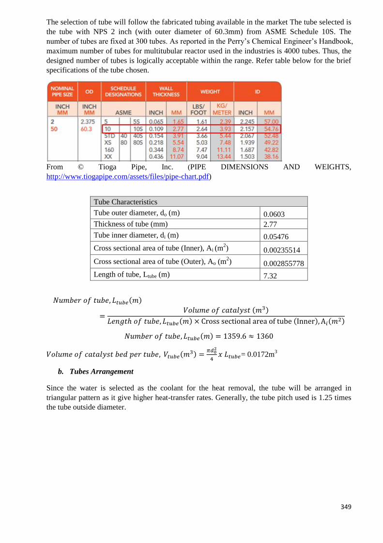
349
The selection of tube will follow the fabricated tubing available in the market The tube selected is
the tube with NPS 2 inch (with outer diameter of 60.3mm) from ASME Schedule 10S. The
number of tubes are fixed at 300 tubes. As reported in the Perry’s Chemical Engineer’s Handbook,
maximum number of tubes for multitubular reactor used in the industries is 4000 tubes. Thus, the
designed number of tubes is logically acceptable within the range. Refer table below for the brief
specifications of the tube chosen.
From © Tioga Pipe, Inc. (PIPE DIMENSIONS AND WEIGHTS,
http://www.tiogapipe.com/assets/files/pipe-chart.pdf)
Tube Characteristics
Tube outer diameter, do (m) 0.0603
Thickness of tube (mm) 2.77
Tube inner diameter, di (m) 0.05476
Cross sectional area of tube (Inner), Ai (m2) 0.00235514
Cross sectional area of tube (Outer), Ao (m2) 0.002855778
Length of tube, Ltube (m) 7.32
𝑁𝑢𝑚𝑏𝑒𝑟 𝑜𝑓 𝑡𝑢𝑏𝑒, 𝐿𝑡𝑢𝑏𝑒(𝑚)
=𝑉𝑜𝑙𝑢𝑚𝑒 𝑜𝑓 𝑐𝑎𝑡𝑎𝑙𝑦𝑠𝑡 (𝑚3)
𝐿𝑒𝑛𝑔𝑡ℎ 𝑜𝑓 𝑡𝑢𝑏𝑒, 𝐿𝑡𝑢𝑏𝑒(𝑚) × Cross sectional area of tube (Inner), A𝑖(𝑚2)
𝑁𝑢𝑚𝑏𝑒𝑟 𝑜𝑓 𝑡𝑢𝑏𝑒, 𝐿𝑡𝑢𝑏𝑒(𝑚) = 1359.6 ≈ 1360
𝑉𝑜𝑙𝑢𝑚𝑒 𝑜𝑓 𝑐𝑎𝑡𝑎𝑙𝑦𝑠𝑡 𝑏𝑒𝑑 𝑝𝑒𝑟 𝑡𝑢𝑏𝑒, 𝑉𝑡𝑢𝑏𝑒(𝑚3) =
𝜋𝑑02
4𝑥 𝐿𝑡𝑢𝑏𝑒= 0.0172m
3
b. Tubes Arrangement
Since the water is selected as the coolant for the heat removal, the tube will be arranged in
triangular pattern as it give higher heat-transfer rates. Generally, the tube pitch used is 1.25 times
the tube outside diameter.
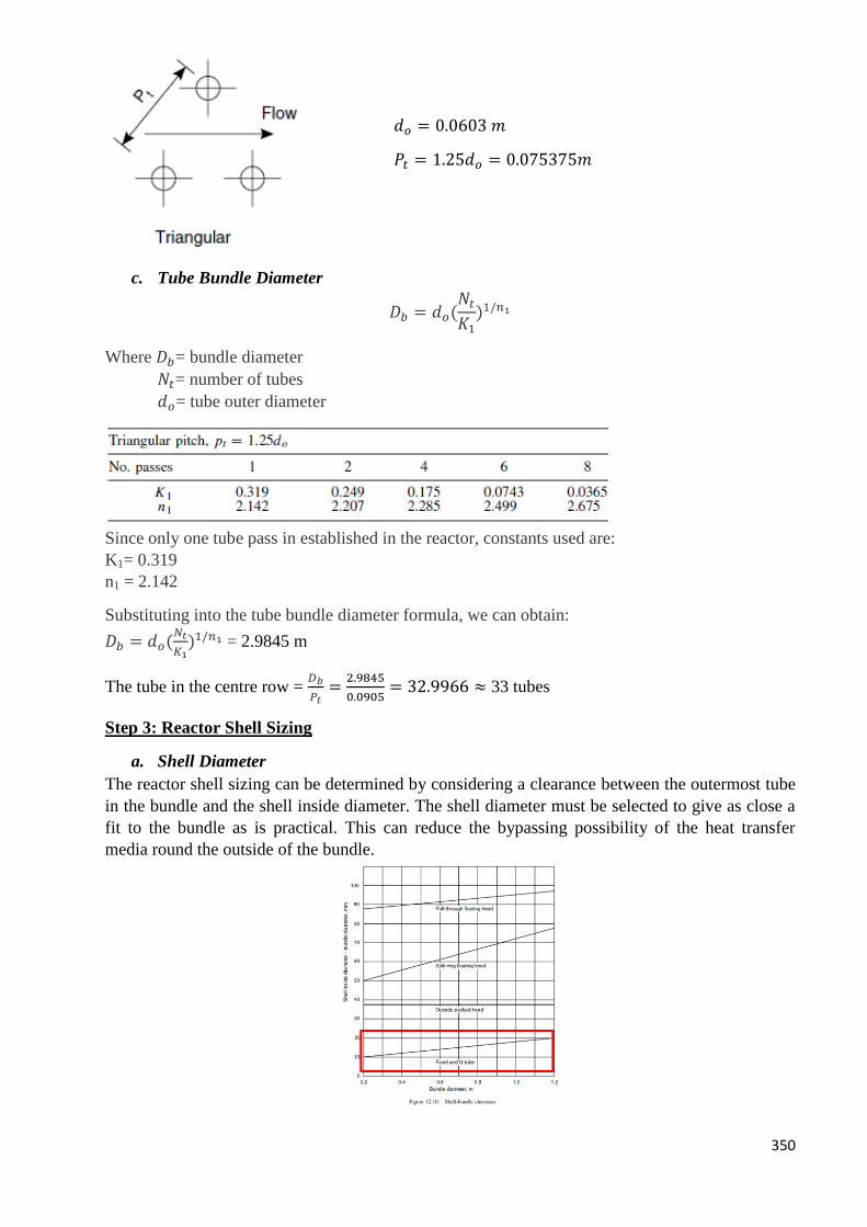
350
c. Tube Bundle Diameter
𝐷𝑏 = 𝑑𝑜(𝑁𝑡
𝐾1)1/𝑛1
Where 𝐷𝑏= bundle diameter
𝑁𝑡= number of tubes
𝑑𝑜= tube outer diameter
Since only one tube pass in established in the reactor, constants used are:
K1= 0.319
n1 = 2.142
Substituting into the tube bundle diameter formula, we can obtain:
𝐷𝑏 = 𝑑𝑜(𝑁𝑡
𝐾1)1/𝑛1 = 2.9845 m
The tube in the centre row = 𝐷𝑏
𝑃𝑡=
2.9845
0.0905= 32.9966 ≈ 33 tubes
Step 3: Reactor Shell Sizing
a. Shell Diameter
The reactor shell sizing can be determined by considering a clearance between the outermost tube
in the bundle and the shell inside diameter. The shell diameter must be selected to give as close a
fit to the bundle as is practical. This can reduce the bypassing possibility of the heat transfer
media round the outside of the bundle.
𝑑𝑜 = 0.0603 𝑚
𝑃𝑡 = 1.25𝑑𝑜 = 0.075375𝑚
351
Based on the plot as shown above, an equation has been established to correlate the bundle
diameter and the clearance for fixed tube type.
Clearance, C (mm) = 10 Db + 8
With the bundle diameter, Db of 2.9845 m, clearance calculated is 37.85 mm.
Shell Diameter, Ds = Db + C = 3.0224 m ≈ 3.1 m
b. Baffle Configuration
Baffles are used in the shell to direct the fluid stream across the tubes, to increase the fluid
velocity, and so to improve the rate of heat transfer. Single segmental baffle with 25% baffle cut
will be used for optimum heat transfer rate. Figure below shows the single segmental baffle.
The baffle spacing used is normally at the range of 0.2 to 1.0 shell diameter. Since close baffle
spacing give higher heat transfer coefficient, factor of 0.25 will be used.
Baffle spacing, lB = 0.25 Ds = 0.775 m
As the tube length used for the catalyst packing is 5.65 m, the number of baffle to be installed can
be calculated as:
NB = Lt / lB = 9.5 ≈ 10 baffles (round of to nearest number)
Step 4: Cooling Requirement
Heat generated from the exothermic reaction will be removed constantly to prevent the buildup of
hot spot which further alter the reaction and cause catalyst deactivation. Water which has the
boiling point temperature of 100oC will be used to constantly remove heat to maintain the catalyst
packed tube temperature at 75 o
C. Generally, at least 10oC of temperature difference will be
implemented. But for ourcase, the coolant return temperature will be set at 50oC .
Shell Side
Water coolant supply temperature, 𝑇𝑠𝑢𝑝𝑝𝑙𝑦(℃) 30
Water coolant return temperature, 𝑇𝑟𝑒𝑡𝑢𝑟𝑛(℃) 50
Mean temperature, 𝑇𝑚𝑒𝑎𝑛(℃) *
40
Fluid properties at mean temperature, 𝑇𝑚𝑒𝑎𝑛(℃)
Density, 𝜌 (𝑘𝑔/𝑚3) 992.2
Viscosity (Pa.s) 0.000653
Thermal Conductivity (𝑊/𝑚℃) 0.6305
Specific Heat Capacity (J/kg℃) 4134.99
352
Prandtl Number, Pr *
4.2826
Tube Side
Catalyst bed temperature, 𝑇𝑊(℃) 75
Fluid properties at wall temperature, 𝑇𝑤(℃)
Density, 𝜌 (𝑘𝑔/𝑚3) 697.77
Viscosity (Pa.s) 0.00095
Thermal Conductivity (𝑊/𝑚℃) 0.0486
Specific Heat Capacity (J/kg℃) 1770.89
Prandtl Number, Pr * 2.8355
* 𝑀𝑒𝑎𝑛 𝑡𝑒𝑚𝑝𝑒𝑟𝑎𝑡𝑢𝑟𝑒, 𝑇𝑓 =𝑇𝑠𝑢𝑝𝑝𝑙𝑦+𝑇𝑟𝑒𝑡𝑢𝑟𝑛
2 ; 𝑃𝑟 =
𝐶𝑝𝜇
𝑘𝑓
a. Log Mean Temperature Difference, ∆𝑻𝑳𝑴𝑻𝑫
For counter current flow,
∆𝑇𝐿𝑀𝑇𝐷 =(𝑇1 − 𝑡2) − (𝑇2 − 𝑡1)
ln[(𝑇1 − 𝑡2) (𝑇2 − 𝑡1)⁄ ]
Where
𝑇1 = ℎ𝑜𝑡 𝑖𝑛𝑙𝑒𝑡 𝑓𝑙𝑢𝑖𝑑 𝑡𝑒𝑚𝑝𝑒𝑟𝑎𝑡𝑢𝑟𝑒
𝑇2 = ℎ𝑜𝑡 𝑜𝑢𝑡𝑙𝑒𝑡 𝑓𝑙𝑢𝑖𝑑 𝑡𝑒𝑚𝑝𝑒𝑟𝑎𝑡𝑢𝑟𝑒
𝑡1 = 𝑐𝑜𝑙𝑑 𝑖𝑛𝑙𝑒𝑡 𝑓𝑙𝑢𝑖𝑑 𝑡𝑒𝑚𝑝𝑒𝑟𝑎𝑡𝑢𝑟𝑒
𝑡2 = 𝑐𝑜𝑙𝑑 𝑜𝑢𝑡𝑙𝑒𝑡 𝑓𝑙𝑢𝑖𝑑 𝑡𝑒𝑚𝑝𝑒𝑟𝑎𝑡𝑢𝑟𝑒
∆𝑇𝐿𝑀𝑇𝐷 = 34.03℃
b. Overall Heat Transfer Coefficient
Amount of heat to be constantly removed from the reactor, Q = 180778.85 MJ/hr
𝑁𝑡= 1360 tubes
𝑑𝑜 = 0.0603 m
𝐿𝑡 = 7.32 m
Heat transfer area, A = Total outside tube area = 𝜋𝑑𝑜𝐿𝑡𝑁𝑡 = 1885.895 m2
Overall heat transfer coefficient, 𝑈𝑜 =𝑄
𝐴(∆𝑇𝐿𝑀𝑇𝐷) = 83.0736 W/m
2K
c. Mass Flow of Coolant
Amount of heat to be constantly removed from the reactor, Q = 180778.85 MJ/hr
Cp = 4134.99 J/kg℃
Water coolant supply temperature, 𝑇𝑠𝑢𝑝𝑝𝑙𝑦 = 30 ℃
Water coolant return temperature, 𝑇𝑟𝑒𝑡𝑢𝑟𝑛 = 50 ℃
353
Mass flow rate of water coolant,𝑚𝑠 =𝑄
𝐶𝑝(𝑇𝑟𝑒𝑡𝑢𝑟𝑛−𝑇𝑠𝑢𝑝𝑝𝑙𝑦) = 2.1860 kg/s
d. Tube Side Heat Transfer Coefficient, hi
In order to calculate the tube side heat transfer coefficient, the Nu has to be determined.
𝑁𝑢𝑠𝑠𝑒𝑙𝑡 𝑛𝑢𝑚𝑏𝑒𝑟, 𝑁𝑢 =ℎ𝑖𝑑𝑒
𝑘𝑓
Volumetric flow rate of the gases, �̇� = 65.7506 m3/h = 6.917 m
3/s
Cross sectional area of one tube, Ai = 0.00235514 m2
Total cross sectional area, AI = Ai x Nt = 3.2030 m2
Fluid velocity, ut = �̇�
𝐴𝐼 = 0.005702 m/s
Equivalent diameter, de = inner tube diameter, di = 0.0548 m
𝑅𝑒 =𝜌𝑢𝑡𝑑𝑒
𝜇 = 1228.67
Below a Reynolds number of about 2000 the flow in pipes will be laminar. Providing the natural
convection effects are small, which will normally be so in forced convection, the following
equation can be used to estimate the film heat-transfer coefficient:
𝜇𝑤 is the viscosity at wall temperature of 75oC; since the tube side fluid is evaluated at 75
oC , 𝜇
will equal to 𝜇𝑤.
The equation will then reduce to:
At operating temperature of 75oC, Pr = 2.8355
de = 0.05476 m
L = 7.32 m
Nu = 5.68
de = di = 0.0548 m
kf = 0.05951 𝑊/𝑚℃
ℎ𝑖 =𝑁𝑢 𝑘𝑓
𝑑𝑒 = 34.214 𝑊/𝑚2𝐾
e. Shell Side Heat Transfer Coefficient, ho
The area for cross flow, As for the row of tubes at the shell equator can be calculated as:
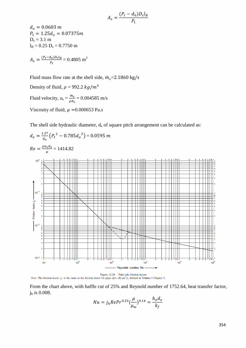
354
𝐴𝑠 =(𝑃𝑡 − 𝑑0)𝐷𝑠𝑙𝐵
𝑃𝑡
𝑑𝑜 = 0.0603 𝑚
𝑃𝑡 = 1.25𝑑𝑜 = 0.07375𝑚
Ds = 3.1 m
lB = 0.25 Ds = 0.7750 m
𝐴𝑠 =(𝑃𝑡−𝑑0)𝐷𝑠𝑙𝐵
𝑃𝑡 = 0.4805 m
2
Fluid mass flow rate at the shell side, �̇�𝑠=2.1860 kg/s
Density of fluid, 𝜌 = 992.2 𝑘𝑔/𝑚3
Fluid velocity, us = �̇�𝑠
𝜌𝐴𝑠 = 0.004585 m/s
Viscosity of fluid, 𝜇 =0.000653 Pa.s
The shell side hydraulic diameter, de of square pitch arrangement can be calculated as:
𝑑𝑒 =1.27
𝑑𝑜(𝑃𝑡
2 − 0.785𝑑𝑜2) = 0.0595 𝑚
𝑅𝑒 =𝜌𝑢𝑠𝑑𝑒
𝜇 = 1414.82
From the chart above, with baffle cut of 25% and Reynold number of 1752.64, heat transfer factor,
jh is 0.008.
𝑁𝑢 = 𝑗ℎ𝑅𝑒𝑃𝑟0.33(𝜇
𝜇𝑤)0.14 =
ℎ𝑜𝑑𝑒
𝑘𝑓
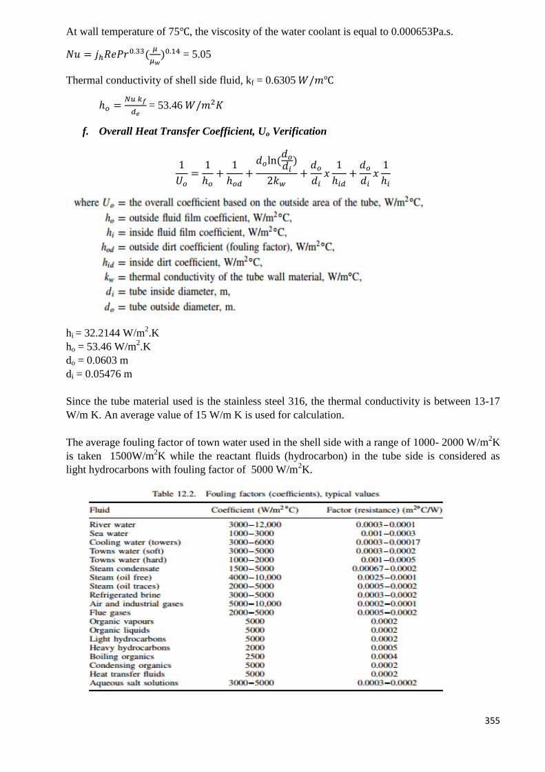
355
At wall temperature of 75℃, the viscosity of the water coolant is equal to 0.000653Pa.s.
𝑁𝑢 = 𝑗ℎ𝑅𝑒𝑃𝑟0.33(𝜇
𝜇𝑤)0.14 = 5.05
Thermal conductivity of shell side fluid, kf = 0.6305 𝑊/𝑚℃
ℎ𝑜 =𝑁𝑢 𝑘𝑓
𝑑𝑒 = 53.46 𝑊/𝑚2𝐾
f. Overall Heat Transfer Coefficient, Uo Verification
1
𝑈𝑜=
1
ℎ𝑜+
1
ℎ𝑜𝑑+
𝑑𝑜ln (𝑑𝑜
𝑑𝑖)
2𝑘𝑤+
𝑑𝑜
𝑑𝑖𝑥
1
ℎ𝑖𝑑+
𝑑𝑜
𝑑𝑖𝑥
1
ℎ𝑖
hi = 32.2144 W/m2.K
ho = 53.46 W/m2.K
do = 0.0603 m
di = 0.05476 m
Since the tube material used is the stainless steel 316, the thermal conductivity is between 13-17
W/m K. An average value of 15 W/m K is used for calculation.
The average fouling factor of town water used in the shell side with a range of 1000- 2000 W/m2K
is taken 1500W/m2K while the reactant fluids (hydrocarbon) in the tube side is considered as
light hydrocarbons with fouling factor of 5000 W/m2K.
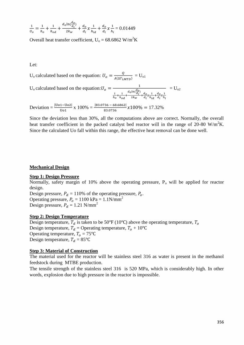
356
1
𝑈𝑜=
1
ℎ𝑜+
1
ℎ𝑜𝑑+
𝑑𝑜ln (𝑑𝑜𝑑𝑖
)
2𝑘𝑤+
𝑑𝑜
𝑑𝑖𝑥
1
ℎ𝑖𝑑+
𝑑𝑜
𝑑𝑖𝑥
1
ℎ𝑖 = 0.01449
Overall heat transfer coefficient, Uo = 68.6862 W/m2K
Let:
Uo calculated based on the equation: 𝑈𝑜 =𝑄
𝐴(∆𝑇𝐿𝑀𝑇𝐷) = Uo1
Uo calculated based on the equation:𝑈𝑜 =1
1
ℎ𝑜+
1
ℎ𝑜𝑑+
𝑑𝑜ln (𝑑𝑜𝑑𝑖
)
2𝑘𝑤+
𝑑𝑜𝑑𝑖
𝑥1
ℎ𝑖𝑑+
𝑑𝑜𝑑𝑖
𝑥1
ℎ𝑖
= Uo2
Deviation = |Uo1−Uo2|
Uo1 x 100% =
|83.0736 − 68.6862|
83.0736𝑥100% = 17.32%
Since the deviation less than 30%, all the computations above are correct. Normally, the overall
heat transfer coefficient in the packed catalyst bed reactor will in the range of 20-80 W/m2K.
Since the calculated Uo fall within this range, the effective heat removal can be done well.
Mechanical Design
Step 1: Design Pressure
Normally, safety margin of 10% above the operating pressure, Po will be applied for reactor
design.
Design pressure, 𝑃𝑑 = 110% of the operating pressure, 𝑃𝑜.
Operating pressure, 𝑃𝑜 = 1100 kPa = 1.1N/mm2
Design pressure, 𝑃𝑑 = 1.21 N/mm2
Step 2: Design Temperature
Design temperature, 𝑇𝑑 is taken to be 50℉ (10℃) above the operating temperature, 𝑇𝑜
Design temperature, 𝑇𝑑 = Operating temperature, 𝑇𝑜 + 10℃
Operating temperature, 𝑇𝑜 = 75℃
Design temperature, 𝑇𝑑 = 85℃
Step 3: Material of Construction
The material used for the reactor will be stainless steel 316 as water is present in the methanol
feedstock during MTBE production.
The tensile strength of the stainless steel 316 is 520 MPa, which is considerably high. In other
words, explosion due to high pressure in the reactor is impossible.
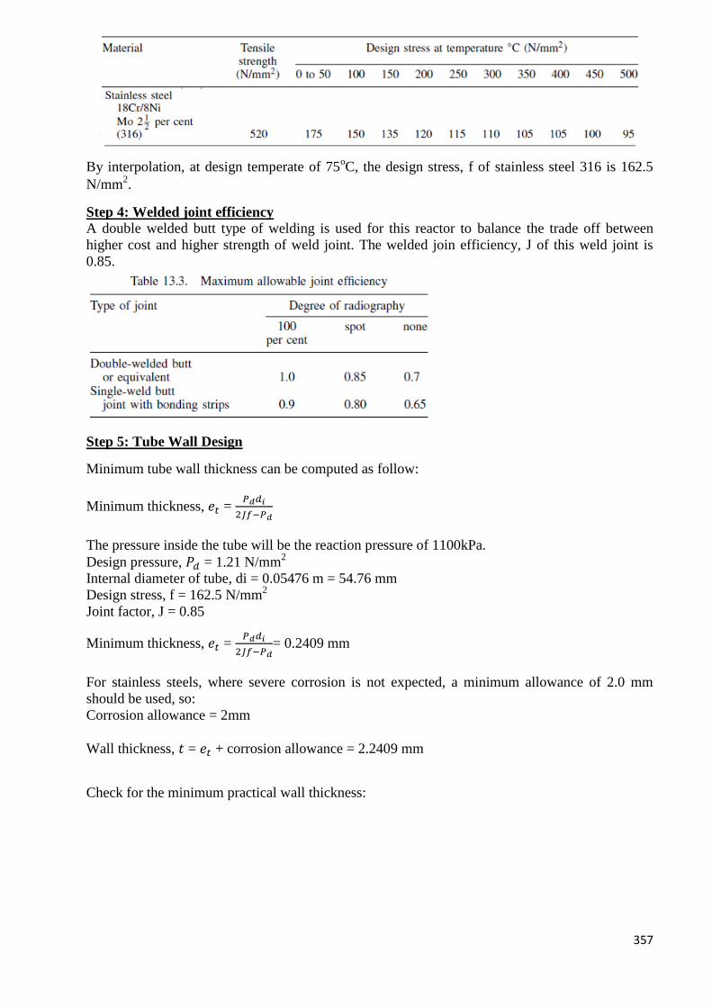
357
By interpolation, at design temperate of 75oC, the design stress, f of stainless steel 316 is 162.5
N/mm2.
Step 4: Welded joint efficiency
A double welded butt type of welding is used for this reactor to balance the trade off between
higher cost and higher strength of weld joint. The welded join efficiency, J of this weld joint is
0.85.
Step 5: Tube Wall Design
Minimum tube wall thickness can be computed as follow:
Minimum thickness, 𝑒𝑡 = 𝑃𝑑𝑑𝑖
2𝐽𝑓−𝑃𝑑
The pressure inside the tube will be the reaction pressure of 1100kPa.
Design pressure, 𝑃𝑑 = 1.21 N/mm2
Internal diameter of tube, di = 0.05476 m = 54.76 mm
Design stress, f = 162.5 N/mm2
Joint factor, J = 0.85
Minimum thickness, 𝑒𝑡 = 𝑃𝑑𝑑𝑖
2𝐽𝑓−𝑃𝑑= 0.2409 mm
For stainless steels, where severe corrosion is not expected, a minimum allowance of 2.0 mm
should be used, so:
Corrosion allowance = 2mm
Wall thickness, 𝑡 = 𝑒𝑡 + corrosion allowance = 2.2409 mm
Check for the minimum practical wall thickness:
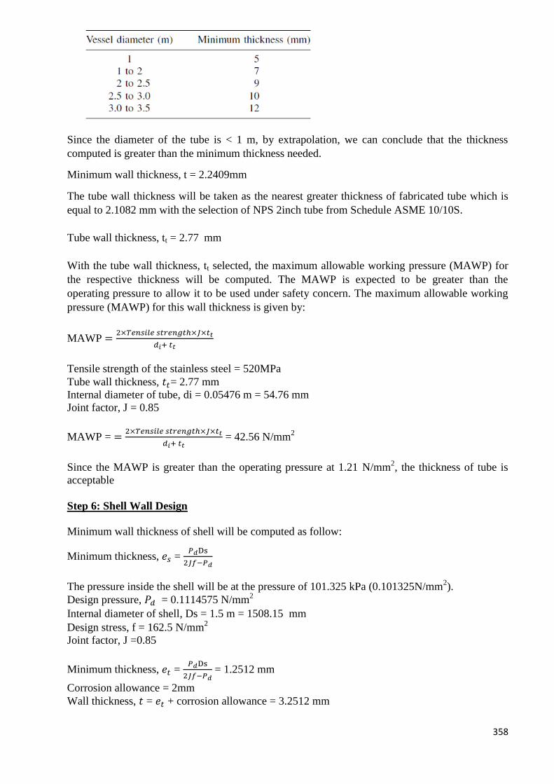
358
Since the diameter of the tube is < 1 m, by extrapolation, we can conclude that the thickness
computed is greater than the minimum thickness needed.
Minimum wall thickness, t = 2.2409mm
The tube wall thickness will be taken as the nearest greater thickness of fabricated tube which is
equal to 2.1082 mm with the selection of NPS 2inch tube from Schedule ASME 10/10S.
Tube wall thickness, tt = 2.77 mm
With the tube wall thickness, tt selected, the maximum allowable working pressure (MAWP) for
the respective thickness will be computed. The MAWP is expected to be greater than the
operating pressure to allow it to be used under safety concern. The maximum allowable working
pressure (MAWP) for this wall thickness is given by:
MAWP =2×𝑇𝑒𝑛𝑠𝑖𝑙𝑒 𝑠𝑡𝑟𝑒𝑛𝑔𝑡ℎ×𝐽×𝑡𝑡
𝑑𝑖+ 𝑡𝑡
Tensile strength of the stainless steel = 520MPa
Tube wall thickness, 𝑡𝑡= 2.77 mm
Internal diameter of tube, di = 0.05476 m = 54.76 mm
Joint factor, J = 0.85
MAWP = =2×𝑇𝑒𝑛𝑠𝑖𝑙𝑒 𝑠𝑡𝑟𝑒𝑛𝑔𝑡ℎ×𝐽×𝑡𝑡
𝑑𝑖+ 𝑡𝑡 = 42.56 N/mm
2
Since the MAWP is greater than the operating pressure at 1.21 N/mm2, the thickness of tube is
acceptable
Step 6: Shell Wall Design
Minimum wall thickness of shell will be computed as follow:
Minimum thickness, 𝑒𝑠 = 𝑃𝑑Ds
2𝐽𝑓−𝑃𝑑
The pressure inside the shell will be at the pressure of 101.325 kPa (0.101325N/mm2).
Design pressure, 𝑃𝑑 = 0.1114575 N/mm2
Internal diameter of shell, Ds = 1.5 m = 1508.15 mm
Design stress, f = 162.5 N/mm2
Joint factor, J =0.85
Minimum thickness, 𝑒𝑡 = 𝑃𝑑Ds
2𝐽𝑓−𝑃𝑑 = 1.2512 mm
Corrosion allowance = 2mm
Wall thickness, 𝑡 = 𝑒𝑡 + corrosion allowance = 3.2512 mm
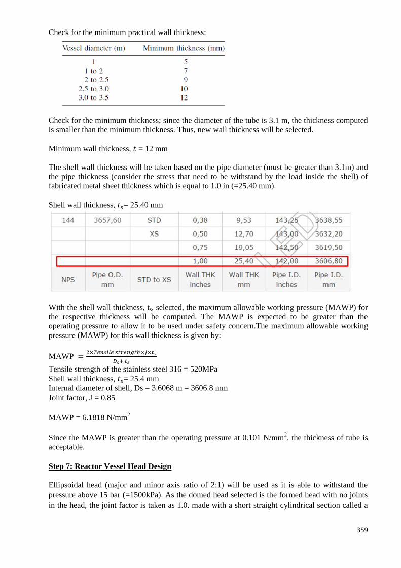
359
Check for the minimum practical wall thickness:
Check for the minimum thickness; since the diameter of the tube is 3.1 m, the thickness computed
is smaller than the minimum thickness. Thus, new wall thickness will be selected.
Minimum wall thickness, 𝑡 = 12 mm
The shell wall thickness will be taken based on the pipe diameter (must be greater than 3.1m) and
the pipe thickness (consider the stress that need to be withstand by the load inside the shell) of
fabricated metal sheet thickness which is equal to 1.0 in (=25.40 mm).
Shell wall thickness, 𝑡𝑠= 25.40 mm
With the shell wall thickness, ts, selected, the maximum allowable working pressure (MAWP) for
the respective thickness will be computed. The MAWP is expected to be greater than the
operating pressure to allow it to be used under safety concern.The maximum allowable working
pressure (MAWP) for this wall thickness is given by:
MAWP =2×𝑇𝑒𝑛𝑠𝑖𝑙𝑒 𝑠𝑡𝑟𝑒𝑛𝑔𝑡ℎ×𝐽×𝑡𝑠
𝐷𝑠+ 𝑡𝑠
Tensile strength of the stainless steel 316 = 520MPa
Shell wall thickness, 𝑡𝑠= 25.4 mm
Internal diameter of shell, Ds = 3.6068 m = 3606.8 mm
Joint factor, J = 0.85
MAWP = 6.1818 N/mm2
Since the MAWP is greater than the operating pressure at 0.101 N/mm2, the thickness of tube is
acceptable.
Step 7: Reactor Vessel Head Design
Ellipsoidal head (major and minor axis ratio of 2:1) will be used as it is able to withstand the
pressure above 15 bar (=1500kPa). As the domed head selected is the formed head with no joints
in the head, the joint factor is taken as 1.0. made with a short straight cylindrical section called a
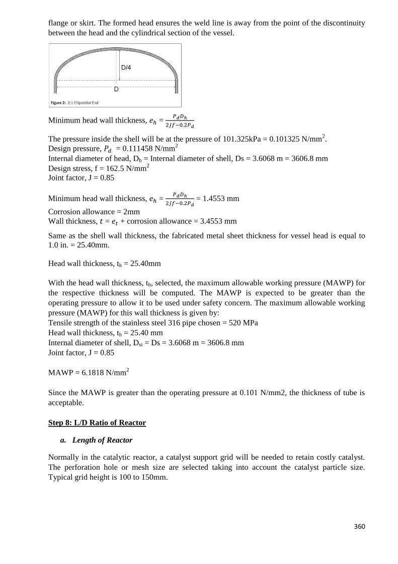
360
flange or skirt. The formed head ensures the weld line is away from the point of the discontinuity
between the head and the cylindrical section of the vessel.
Minimum head wall thickness, 𝑒ℎ = 𝑃𝑑𝐷ℎ
2𝐽𝑓−0.2𝑃𝑑
The pressure inside the shell will be at the pressure of 101.325kPa = 0.101325 N/mm2.
Design pressure, 𝑃𝑑 = 0.111458 N/mm2
Internal diameter of head, Dh = Internal diameter of shell, Ds = 3.6068 m = 3606.8 mm
Design stress, f = 162.5 N/mm2
Joint factor, J = 0.85
Minimum head wall thickness, 𝑒ℎ = 𝑃𝑑𝐷ℎ
2𝐽𝑓−0.2𝑃𝑑 = 1.4553 mm
Corrosion allowance = 2mm
Wall thickness, 𝑡 = 𝑒𝑡 + corrosion allowance = 3.4553 mm
Same as the shell wall thickness, the fabricated metal sheet thickness for vessel head is equal to
1.0 in. = 25.40mm.
Head wall thickness, th = 25.40mm
With the head wall thickness, th, selected, the maximum allowable working pressure (MAWP) for
the respective thickness will be computed. The MAWP is expected to be greater than the
operating pressure to allow it to be used under safety concern. The maximum allowable working
pressure (MAWP) for this wall thickness is given by:
Tensile strength of the stainless steel 316 pipe chosen = 520 MPa
Head wall thickness, th = 25.40 mm
Internal diameter of shell, Dsi = Ds = 3.6068 m = 3606.8 mm
Joint factor, J = 0.85
MAWP = 6.1818 N/mm2
Since the MAWP is greater than the operating pressure at 0.101 N/mm2, the thickness of tube is
acceptable.
Step 8: L/D Ratio of Reactor
a. Length of Reactor
Normally in the catalytic reactor, a catalyst support grid will be needed to retain costly catalyst.
The perforation hole or mesh size are selected taking into account the catalyst particle size.
Typical grid height is 100 to 150mm.
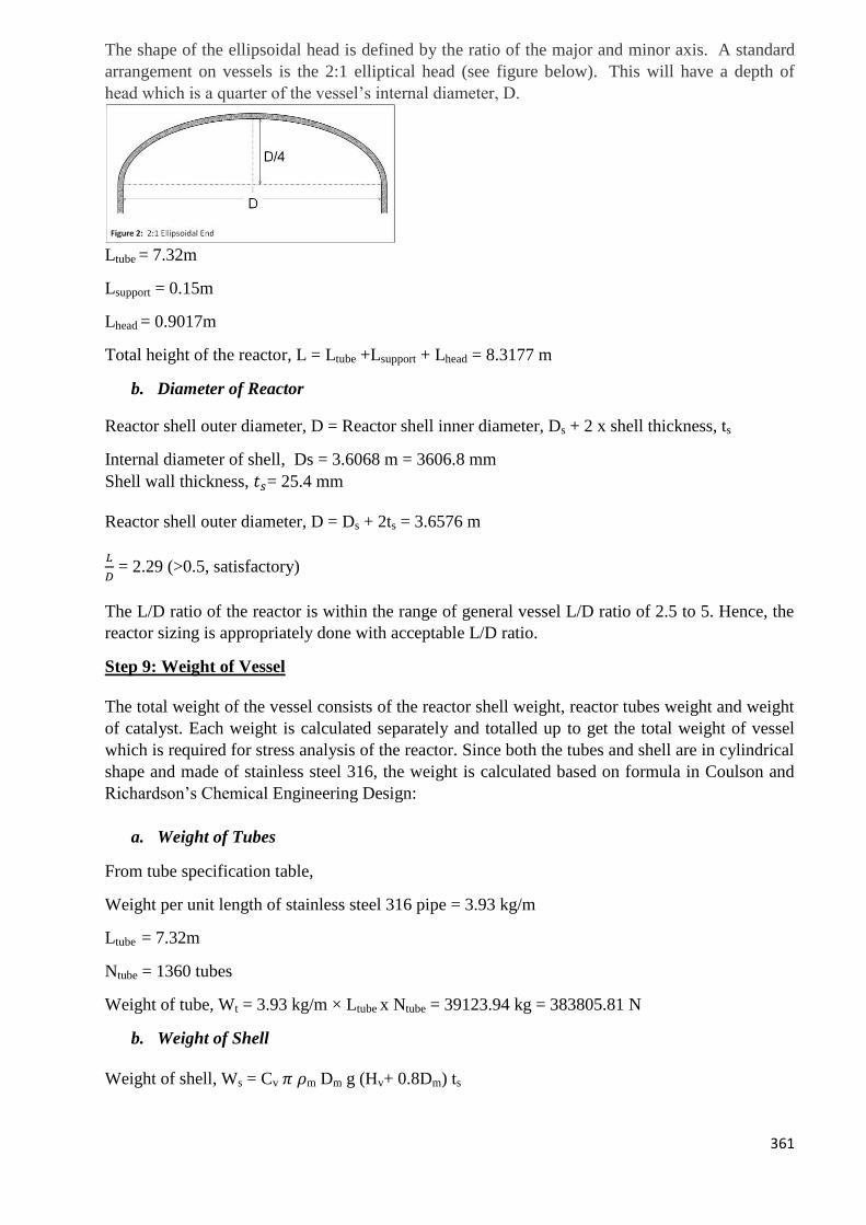
361
The shape of the ellipsoidal head is defined by the ratio of the major and minor axis. A standard
arrangement on vessels is the 2:1 elliptical head (see figure below). This will have a depth of
head which is a quarter of the vessel’s internal diameter, D.
Ltube = 7.32m
Lsupport = 0.15m
Lhead = 0.9017m
Total height of the reactor, L = Ltube +Lsupport + Lhead = 8.3177 m
b. Diameter of Reactor
Reactor shell outer diameter, D = Reactor shell inner diameter, Ds + 2 x shell thickness, ts
Internal diameter of shell, Ds = 3.6068 m = 3606.8 mm
Shell wall thickness, 𝑡𝑠= 25.4 mm
Reactor shell outer diameter, D = Ds + 2ts = 3.6576 m
𝐿
𝐷 = 2.29 (>0.5, satisfactory)
The L/D ratio of the reactor is within the range of general vessel L/D ratio of 2.5 to 5. Hence, the
reactor sizing is appropriately done with acceptable L/D ratio.
Step 9: Weight of Vessel
The total weight of the vessel consists of the reactor shell weight, reactor tubes weight and weight
of catalyst. Each weight is calculated separately and totalled up to get the total weight of vessel
which is required for stress analysis of the reactor. Since both the tubes and shell are in cylindrical
shape and made of stainless steel 316, the weight is calculated based on formula in Coulson and
Richardson’s Chemical Engineering Design:
a. Weight of Tubes
From tube specification table,
Weight per unit length of stainless steel 316 pipe = 3.93 kg/m
Ltube = 7.32m
Ntube = 1360 tubes
Weight of tube, Wt = 3.93 kg/m × Ltube x Ntube = 39123.94 kg = 383805.81 N
b. Weight of Shell
Weight of shell, Ws = Cv 𝜋 𝜌m Dm g (Hv+ 0.8Dm) ts
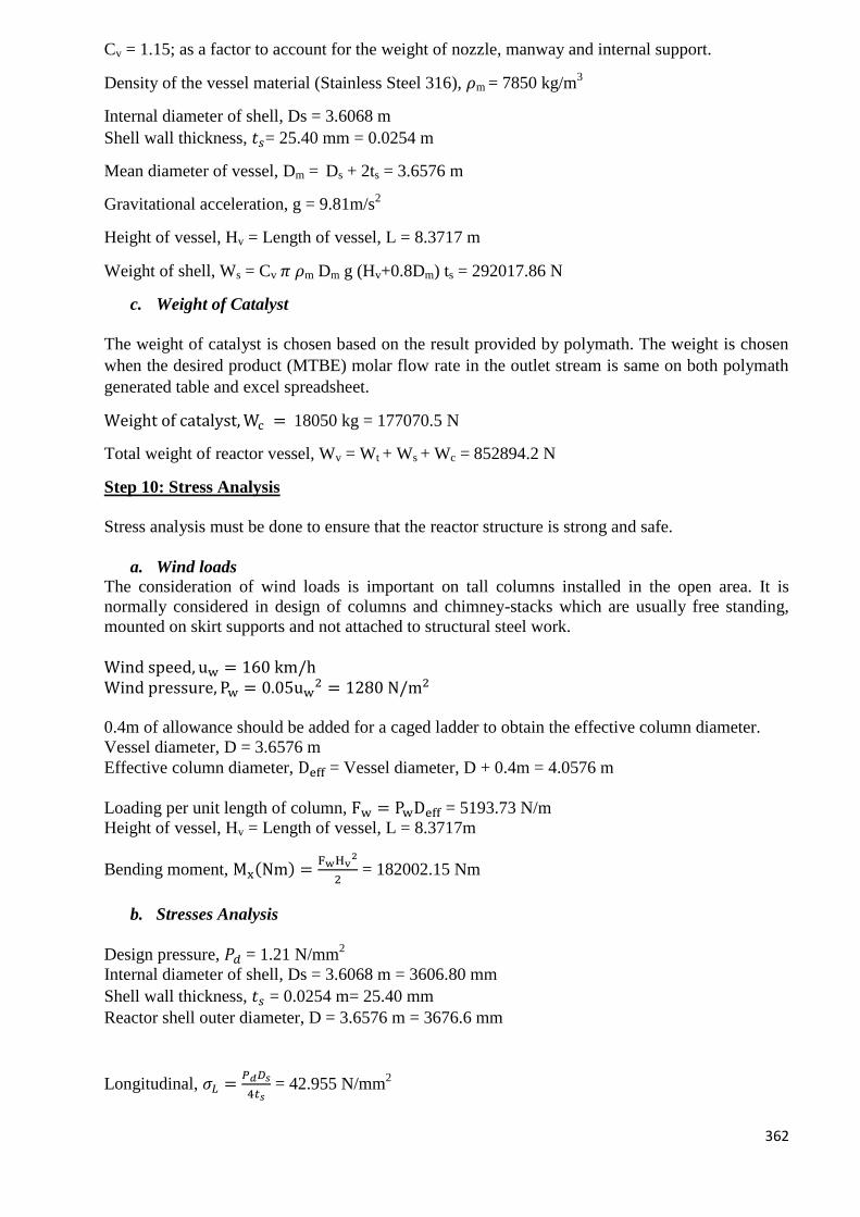
362
Cv = 1.15; as a factor to account for the weight of nozzle, manway and internal support.
Density of the vessel material (Stainless Steel 316), 𝜌m = 7850 kg/m3
Internal diameter of shell, Ds = 3.6068 m
Shell wall thickness, 𝑡𝑠= 25.40 mm = 0.0254 m
Mean diameter of vessel, Dm = Ds + 2ts = 3.6576 m
Gravitational acceleration, g = 9.81m/s2
Height of vessel, Hv = Length of vessel, L = 8.3717 m
Weight of shell, Ws = Cv 𝜋 𝜌m Dm g (Hv+0.8Dm) ts = 292017.86 N
c. Weight of Catalyst
The weight of catalyst is chosen based on the result provided by polymath. The weight is chosen
when the desired product (MTBE) molar flow rate in the outlet stream is same on both polymath
generated table and excel spreadsheet.
Weight of catalyst,Wc = 18050 kg = 177070.5 N
Total weight of reactor vessel, Wv = Wt + Ws + Wc = 852894.2 N
Step 10: Stress Analysis
Stress analysis must be done to ensure that the reactor structure is strong and safe.
a. Wind loads
The consideration of wind loads is important on tall columns installed in the open area. It is
normally considered in design of columns and chimney-stacks which are usually free standing,
mounted on skirt supports and not attached to structural steel work.
Wind speed, uw = 160 km/h
Wind pressure, Pw = 0.05uw2 = 1280 N/m2
0.4m of allowance should be added for a caged ladder to obtain the effective column diameter.
Vessel diameter, D = 3.6576 m
Effective column diameter, Deff = Vessel diameter, D + 0.4m = 4.0576 m
Loading per unit length of column, Fw = PwDeff = 5193.73 N/m
Height of vessel, Hv = Length of vessel, L = 8.3717m
Bending moment, Mx(Nm) =FwHv
2
2 = 182002.15 Nm
b. Stresses Analysis
Design pressure, 𝑃𝑑 = 1.21 N/mm2
Internal diameter of shell, Ds = 3.6068 m = 3606.80 mm
Shell wall thickness, 𝑡𝑠 = 0.0254 m= 25.40 mm
Reactor shell outer diameter, D = 3.6576 m = 3676.6 mm
Longitudinal, 𝜎𝐿 =𝑃𝑑𝐷𝑠
4𝑡𝑠 = 42.955 N/mm
2
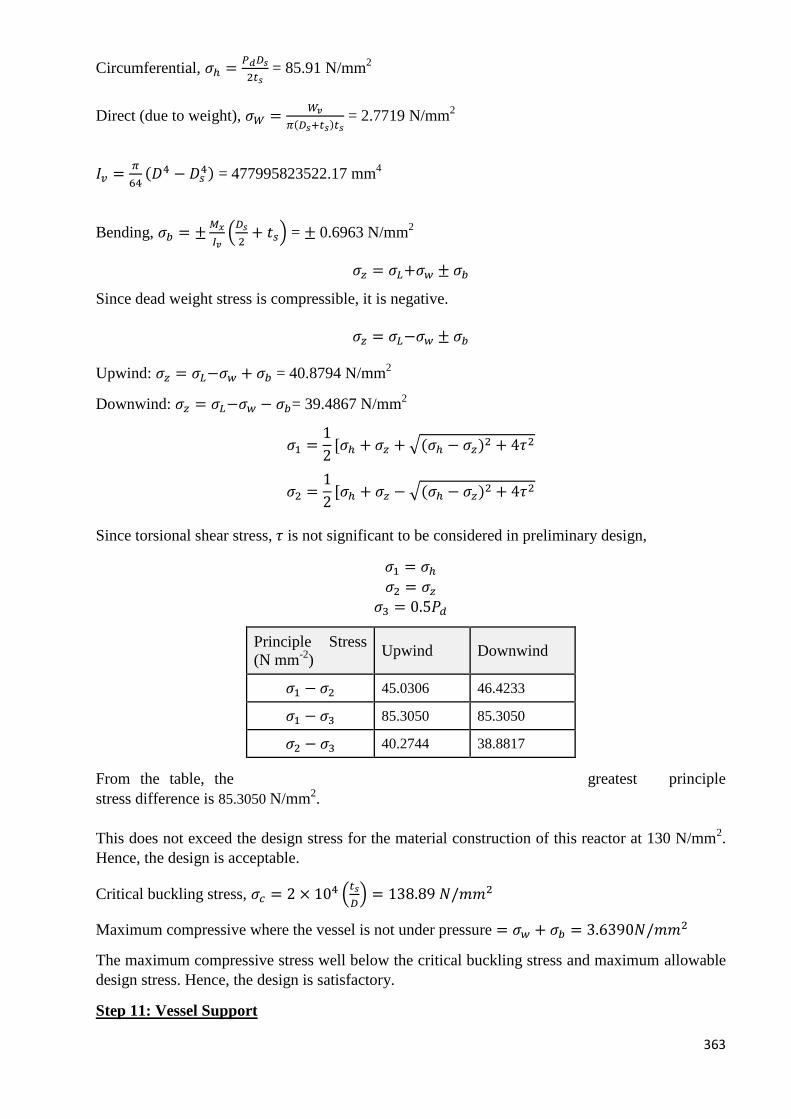
363
Circumferential, 𝜎ℎ =𝑃𝑑𝐷𝑠
2𝑡𝑠 = 85.91 N/mm
2
Direct (due to weight), 𝜎𝑊 =𝑊𝑣
𝜋(𝐷𝑠+𝑡𝑠)𝑡𝑠 = 2.7719 N/mm
2
𝐼𝑣 =𝜋
64(𝐷4 − 𝐷𝑠
4) = 477995823522.17 mm4
Bending, 𝜎𝑏 = ±𝑀𝑥
𝐼𝑣(𝐷𝑠
2+ 𝑡𝑠) = ± 0.6963 N/mm
2
𝜎𝑧 = 𝜎𝐿+𝜎𝑤 ± 𝜎𝑏
Since dead weight stress is compressible, it is negative.
𝜎𝑧 = 𝜎𝐿−𝜎𝑤 ± 𝜎𝑏
Upwind: 𝜎𝑧 = 𝜎𝐿−𝜎𝑤 + 𝜎𝑏 = 40.8794 N/mm2
Downwind: 𝜎𝑧 = 𝜎𝐿−𝜎𝑤 − 𝜎𝑏= 39.4867 N/mm2
𝜎1 =1
2[𝜎ℎ + 𝜎𝑧 + √(𝜎ℎ − 𝜎𝑧)2 + 4𝜏2
𝜎2 =1
2[𝜎ℎ + 𝜎𝑧 − √(𝜎ℎ − 𝜎𝑧)2 + 4𝜏2
Since torsional shear stress, 𝜏 is not significant to be considered in preliminary design,
𝜎1 = 𝜎ℎ
𝜎2 = 𝜎𝑧
𝜎3 = 0.5𝑃𝑑
From the table, the greatest principle
stress difference is 85.3050 N/mm2.
This does not exceed the design stress for the material construction of this reactor at 130 N/mm2.
Hence, the design is acceptable.
Critical buckling stress, 𝜎𝑐 = 2 × 10⁴ (𝑡𝑠
𝐷) = 138.89 𝑁/𝑚𝑚2
Maximum compressive where the vessel is not under pressure = 𝜎𝑤 + 𝜎𝑏 = 3.6390𝑁/𝑚𝑚2
The maximum compressive stress well below the critical buckling stress and maximum allowable
design stress. Hence, the design is satisfactory.
Step 11: Vessel Support
Principle Stress
(N mm-2
) Upwind Downwind
𝜎1 − 𝜎2 45.0306 46.4233
𝜎1 − 𝜎3 85.3050 85.3050
𝜎2 − 𝜎3 40.2744 38.8817
364
Type of support chosen: Conical Skirt
Approximate skirt bottom diameter, Dskirt = Ds+ 0.1 = 3.7068 m
Approximate skirt height, Hskirt = 3.0 m
𝑡𝑎𝑛 𝜃𝑠𝑘𝑖𝑟𝑡 =𝐻𝑠𝑘𝑖𝑟𝑡
12
(𝐷𝑠𝑘𝑖𝑟𝑡 − 𝐼𝐷𝑠)= 9.8879
The skirt base angle,𝜃𝑠 = 89.05° is acceptable which is within common range of 80° 𝑡𝑜 90°
Total height of the reactor, L = 8.2717m
Loading per unit length of column, Fw = 5193.73 N/m
Bending moment at bottom of skirt, 𝑀𝑠 =𝐹𝑤(𝐿+𝐻𝑠𝑘𝑖𝑟𝑡)
2
2= 335814.92 𝑁 𝑚
Take skirt thickness, tskirt = ts = 0.00254m
Bending stress in skirt, 𝜎𝑏𝑠 =4𝑀𝑠
𝜋(𝐷𝑠𝑘𝑖𝑟𝑡+𝑡𝑠𝑘𝑖𝑟𝑡)𝐷𝑠𝑘𝑖𝑟𝑡𝑡𝑠𝑘𝑖𝑟𝑡= 12.168 𝑁 𝑚𝑚−2
The maximum dead weight load on the skirt will occur when the vessel space is full of water.
Volume of shell, Vs = 𝜋𝐷𝑠
2
4𝑥 𝐿 = 55.25 m
3
Volume of tube, Vt = 𝜋𝑑𝑜
2
4𝑥 𝐿 𝑥 𝑁𝑡 = 28.42 m
3
Volume of water, Vwater = Volume of shell, Vs – Volume of tube, Vtube = 25.824 m3
Approximate water weight, 𝑊𝑤𝑎𝑡𝑒𝑟 = 𝑉𝑤𝑎𝑡𝑒𝑟 × 𝜌𝑤𝑎𝑡𝑒𝑟 × 𝑔 = 261094.81N
Total weight of reactor vessel, Wv = Wt + Ws + Wc = 852894.2 N
Total Weight of reactor including coolant and reactant, WTOTAL = Wt + Ws + Wc + Wwater +
Wreactants = 1130348.8 N
Dead weight stress in the skirt,
𝜎𝑤𝑠(𝑡𝑒𝑠𝑡) =𝑊𝑤𝑎𝑡𝑒𝑟+ 𝑊𝑣
𝜋(𝐷𝑠𝑘𝑖𝑟𝑡+𝑡𝑠𝑘𝑖𝑟𝑡)𝑡𝑠𝑘𝑖𝑟𝑡=3.74 𝑁/ 𝑚𝑚2
𝜎𝑤𝑠(𝑜𝑝𝑒𝑟𝑎𝑡𝑖𝑛𝑔) =𝑊𝑣
𝜋(𝐷𝑠𝑘𝑖𝑟𝑡+𝑡𝑠𝑘𝑖𝑟𝑡)𝑡𝑠𝑘𝑖𝑟𝑡= 2.86 𝑁/ 𝑚𝑚2
𝜎𝑠(𝑡𝑒𝑛𝑠𝑖𝑙𝑒) = 𝜎𝑏𝑠−𝜎𝑤𝑠
𝜎𝑠(𝑐𝑜𝑚𝑝𝑟𝑒𝑠𝑠𝑖𝑣𝑒) = 𝜎𝑏𝑠+𝜎𝑤𝑠
Maximum σ̂s(compressive) = 12.1678 − 2.8638 =15.9083 N/ mm2
365
Maximum σ̂s(tensile) = 12.1678 − 3.7405 = 8.4273 N/ mm2
The skirt thickness should be such that under the worst combination of wind and dead weight
loading, 2 design criteria must be satisfied:
𝜎𝑠(𝑡𝑒𝑛𝑠𝑖𝑙𝑒) < 𝑓𝑠𝐽 sin 𝜃𝑠
𝜎𝑠(𝑐𝑜𝑚𝑝𝑟𝑒𝑠𝑠𝑖𝑣𝑒) < 0.125𝐸 (𝑡𝑠𝐷𝑠
) 𝑠𝑖𝑛𝜃𝑠
The skirt material is choosen to be stainless steel with maximum allowable design stress ( at
30 °C ) of 135 N/mm2. The Young modulus of stainless steel is 203395.3 MPa.
fs = 135 N/mm2
J = 0.85
𝜃𝑠 = 89.05° E=203395.3 MPa
tskirt = 0.00792m
Dskirt = 1.60815 m
𝑓𝑠𝐽 sin 𝜃𝑠 = 114.7342 N/mm2
Maximum σ̂s(tensile)(8,4273 N/ mm2) < 𝑓𝑠𝐽 sin 𝜃𝑠 [Satisfy]
0.125𝐸 (𝑡𝑠𝑘𝑖𝑟𝑡
𝐷𝑠𝑘𝑖𝑟𝑡) 𝑠𝑖𝑛𝜃𝑠 = 174.1911 N/mm
2
Maximum σ̂s(compressive)(15.9083 N/ mm2) < 0.125𝐸 (𝑡𝑠
𝐷𝑠) 𝑠𝑖𝑛𝜃𝑠 [Satisfy]
Since both design criteria are satisfied, the skirt thickness is acceptable.
Take corrosion allowance of 2 mm, skirt thickness = 25.4 + 2 =27.40 mm
Step 12: Base ring and anchor bolt design
Area of bolt, Ab =1
Nbfb[4Ms
Db− W]
𝑀𝑎𝑥𝑖𝑚𝑢𝑚 𝑎𝑙𝑙𝑜𝑤𝑎𝑏𝑙𝑒 𝑏𝑜𝑙𝑡 𝑠𝑡𝑟𝑒𝑠𝑠, 𝑓𝑏 = 125𝑁
𝑚𝑚2
𝐵𝑒𝑛𝑑𝑖𝑛𝑔 𝑚𝑜𝑚𝑒𝑛𝑡 𝑎𝑡 𝑡ℎ𝑒 𝑏𝑎𝑠𝑒,𝑀𝑠 = 335814.92 𝑁𝑚
Weight of the vessel, W= 852894.2 N
Approximate bolt pitch circle diameter, Db = 3.4 m
Circumference of bolt circle = 3350.8 × π = 10526.85 mm
Minimum bolt spacing is recommended at 600 mm.
𝑁𝑢𝑚𝑏𝑒𝑟 𝑜𝑓 𝑏𝑜𝑙𝑡𝑠, 𝑁𝑏 =10536.85
600= 17.54 ≈ 16 𝑏𝑜𝑙𝑡𝑠 (Must be multiple of 4)
Area of bolt, Ab = 1
𝑁𝑏𝑓𝑏[4𝑀𝑠
𝐷𝑏− 𝑊] = 226.01 𝑚𝑚2
Diameter of bolt = √𝐴𝑏×4
𝜋= 16.96 𝑚𝑚
The bolt type selected is M20 as it is the closest standard size bolt larger than 16.96 mm. Its root
area is 234.77 mm2.
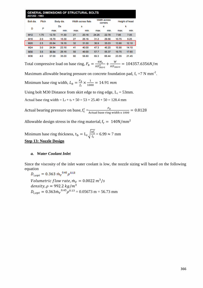
366
Total compressive load on base ring, 𝐹𝑏 =4𝑀𝑠
𝜋𝐷𝑠𝑘𝑖𝑟𝑡2 +
𝑊
𝜋𝐷𝑠𝑘𝑖𝑟𝑡= 104357.6356𝑁/𝑚
Maximum allowable bearing pressure on concrete foundation pad, fc =7 N mm-2
.
Minimum base ring width, 𝐿𝑏 =𝐹𝑏
𝑓𝑐×
1
1000= 14.91 𝑚𝑚
Using bolt M30 Distance from skirt edge to ring edge, Lr = 53mm.
Actual base ring width = Lr + ts + 50 = 53 + 25.40 + 50 = 128.4 mm
Actual bearing pressure on base, fc′ =
𝐹𝑏
Actual base ring width x 1000= 0.8128
Allowable design stress in the ring material, fr = 140N/mm2
Minimum base ring thickness, tb = Lr√3fc
′
fr = 6.99 ≈ 7 mm
Step 13: Nozzle Design
a. Water Coolant Inlet
Since the viscosity of the inlet water coolant is low, the nozzle sizing will based on the following
equation
𝑉𝑜𝑙𝑢𝑚𝑒𝑡𝑟𝑖𝑐 𝑓𝑙𝑜𝑤 𝑟𝑎𝑡𝑒, �̇�𝑉 = 0.0022 𝑚3/𝑠
𝑑𝑒𝑛𝑠𝑖𝑡𝑦, 𝜌 = 992.2 𝑘𝑔/𝑚3
𝐷𝑖,𝑜𝑝𝑡 = 0.363�̇�𝑉0.45𝜌0.13 = 0.05673 m = 56.73 mm
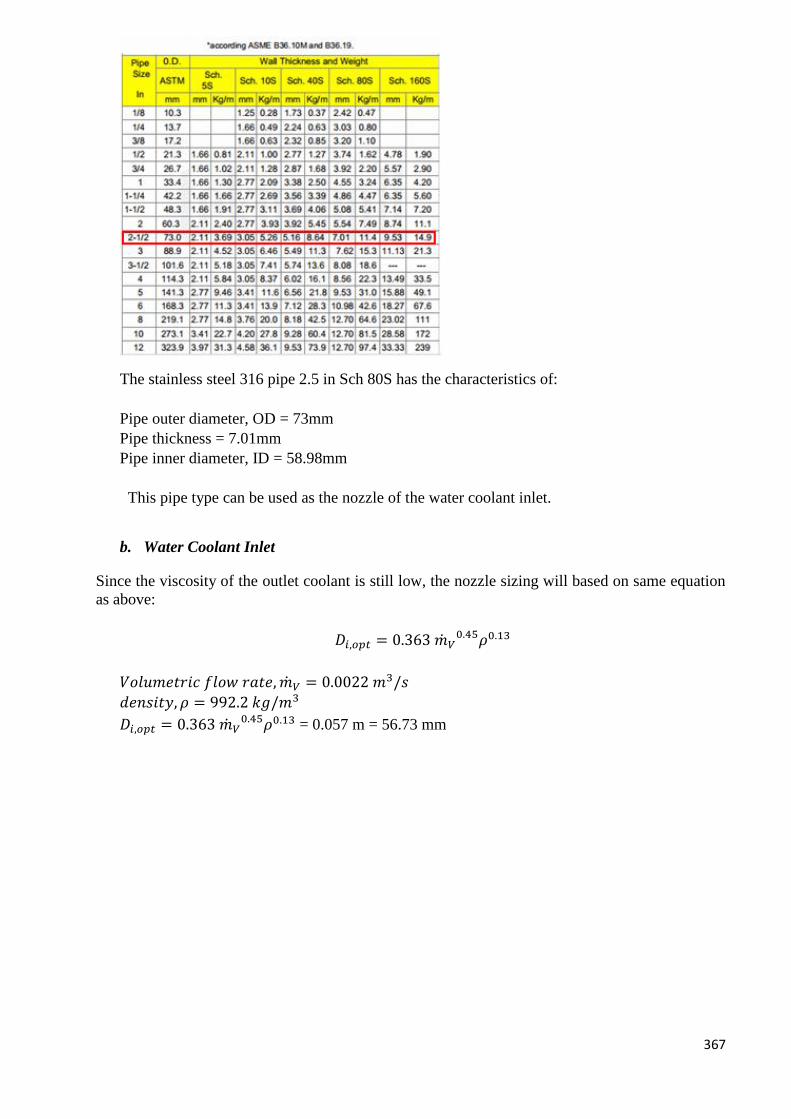
367
The stainless steel 316 pipe 2.5 in Sch 80S has the characteristics of:
Pipe outer diameter, OD = 73mm
Pipe thickness = 7.01mm
Pipe inner diameter, ID = 58.98mm
This pipe type can be used as the nozzle of the water coolant inlet.
b. Water Coolant Inlet
Since the viscosity of the outlet coolant is still low, the nozzle sizing will based on same equation
as above:
𝐷𝑖,𝑜𝑝𝑡 = 0.363 �̇�𝑉0.45𝜌0.13
𝑉𝑜𝑙𝑢𝑚𝑒𝑡𝑟𝑖𝑐 𝑓𝑙𝑜𝑤 𝑟𝑎𝑡𝑒, �̇�𝑉 = 0.0022 𝑚3/𝑠
𝑑𝑒𝑛𝑠𝑖𝑡𝑦, 𝜌 = 992.2 𝑘𝑔/𝑚3
𝐷𝑖,𝑜𝑝𝑡 = 0.363 �̇�𝑉0.45𝜌0.13 = 0.057 m = 56.73 mm
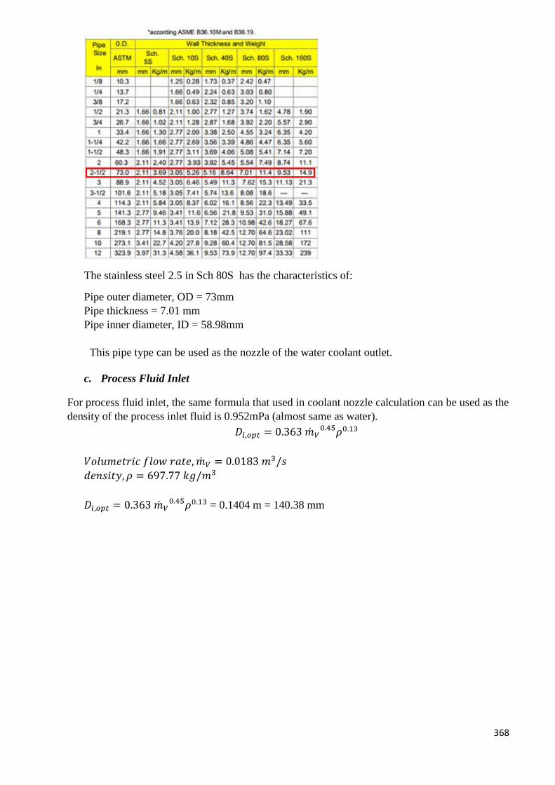
368
The stainless steel 2.5 in Sch 80S has the characteristics of:
Pipe outer diameter, OD = 73mm
Pipe thickness = 7.01 mm
Pipe inner diameter, ID = 58.98mm
This pipe type can be used as the nozzle of the water coolant outlet.
c. Process Fluid Inlet
For process fluid inlet, the same formula that used in coolant nozzle calculation can be used as the
density of the process inlet fluid is 0.952mPa (almost same as water).
𝐷𝑖,𝑜𝑝𝑡 = 0.363 �̇�𝑉0.45𝜌0.13
𝑉𝑜𝑙𝑢𝑚𝑒𝑡𝑟𝑖𝑐 𝑓𝑙𝑜𝑤 𝑟𝑎𝑡𝑒, �̇�𝑉 = 0.0183 𝑚3/𝑠
𝑑𝑒𝑛𝑠𝑖𝑡𝑦, 𝜌 = 697.77 𝑘𝑔/𝑚3
𝐷𝑖,𝑜𝑝𝑡 = 0.363 �̇�𝑉0.45𝜌0.13 = 0.1404 m = 140.38 mm
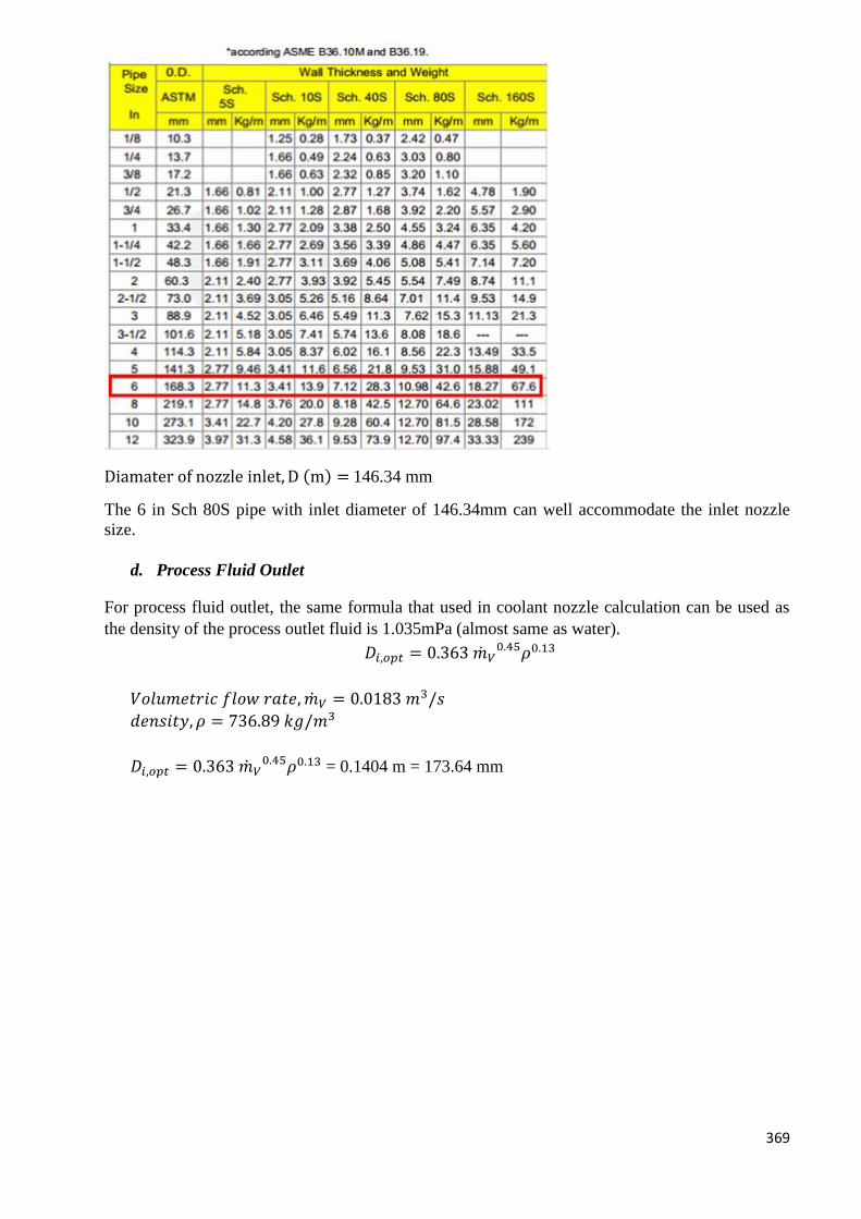
369
Diamater of nozzle inlet, D (m) = 146.34 mm
The 6 in Sch 80S pipe with inlet diameter of 146.34mm can well accommodate the inlet nozzle
size.
d. Process Fluid Outlet
For process fluid outlet, the same formula that used in coolant nozzle calculation can be used as
the density of the process outlet fluid is 1.035mPa (almost same as water).
𝐷𝑖,𝑜𝑝𝑡 = 0.363 �̇�𝑉0.45𝜌0.13
𝑉𝑜𝑙𝑢𝑚𝑒𝑡𝑟𝑖𝑐 𝑓𝑙𝑜𝑤 𝑟𝑎𝑡𝑒, �̇�𝑉 = 0.0183 𝑚3/𝑠
𝑑𝑒𝑛𝑠𝑖𝑡𝑦, 𝜌 = 736.89 𝑘𝑔/𝑚3
𝐷𝑖,𝑜𝑝𝑡 = 0.363 �̇�𝑉0.45𝜌0.13 = 0.1404 m = 173.64 mm
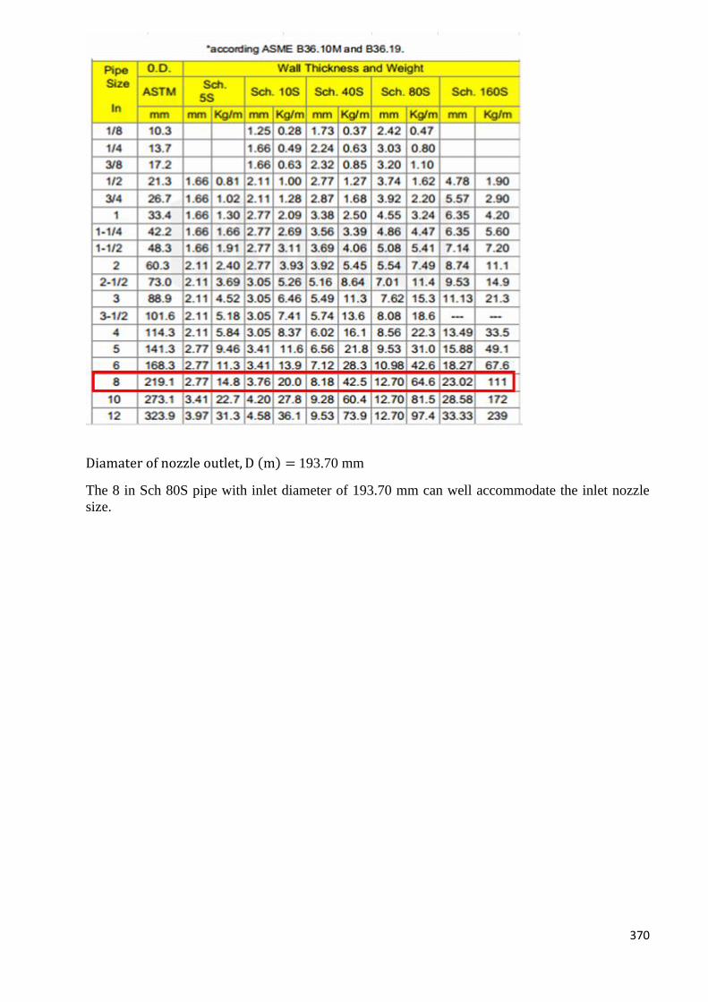
370
Diamater of nozzle outlet, D (m) = 193.70 mm
The 8 in Sch 80S pipe with inlet diameter of 193.70 mm can well accommodate the inlet nozzle
size.
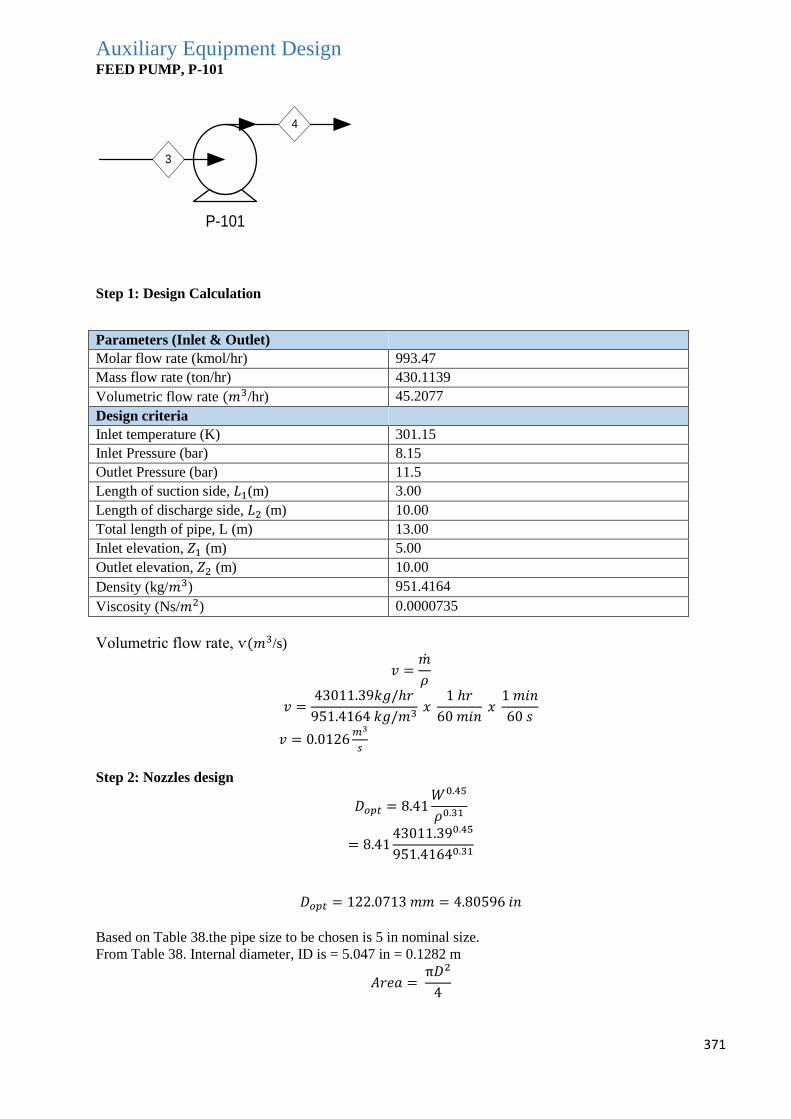
371
Auxiliary Equipment Design FEED PUMP, P-101
P-101
4
3
Step 1: Design Calculation
Parameters (Inlet & Outlet)
Molar flow rate (kmol/hr) 993.47
Mass flow rate (ton/hr) 430.1139
Volumetric flow rate (𝑚3/hr) 45.2077
Design criteria
Inlet temperature (K) 301.15
Inlet Pressure (bar) 8.15
Outlet Pressure (bar) 11.5
Length of suction side, 𝐿1(m) 3.00
Length of discharge side, 𝐿2 (m) 10.00
Total length of pipe, L (m) 13.00
Inlet elevation, 𝑍1 (m) 5.00
Outlet elevation, 𝑍2 (m) 10.00
Density (kg/𝑚3) 951.4164
Viscosity (Ns/𝑚2) 0.0000735
Volumetric flow rate, ѵ(𝑚3/s)
𝑣 =�̇�
𝜌
𝑣 =43011.39𝑘𝑔/ℎ𝑟
951.4164 𝑘𝑔/𝑚3 𝑥
1 ℎ𝑟
60 𝑚𝑖𝑛 𝑥
1 𝑚𝑖𝑛
60 𝑠
𝑣 = 0.0126𝑚3
𝑠
Step 2: Nozzles design
𝐷𝑜𝑝𝑡 = 8.41𝑊0.45
𝜌0.31
= 8.4143011.390.45
951.41640.31
𝐷𝑜𝑝𝑡 = 122.0713 𝑚𝑚 = 4.80596 𝑖𝑛
Based on Table 38.the pipe size to be chosen is 5 in nominal size.
From Table 38. Internal diameter, ID is = 5.047 in = 0.1282 m
𝐴𝑟𝑒𝑎 = π𝐷2
4
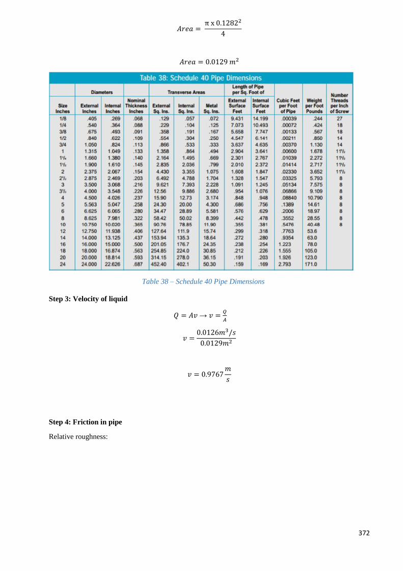
372
𝐴𝑟𝑒𝑎 = π x 0.12822
4
𝐴𝑟𝑒𝑎 = 0.0129 𝑚2
Table 38 – Schedule 40 Pipe Dimensions
Step 3: Velocity of liquid
𝑄 = 𝐴𝑣 → 𝑣 =𝑄
𝐴
𝑣 =0.0126𝑚3/𝑠
0.0129𝑚2
𝑣 = 0.9767𝑚
𝑠
Step 4: Friction in pipe
Relative roughness:
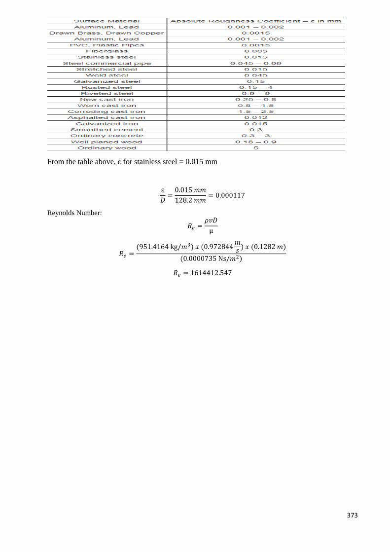
373
From the table above, ɛ for stainless steel = 0.015 mm
ɛ
𝐷=
0.015 𝑚𝑚
128.2 𝑚𝑚= 0.000117
Reynolds Number:
𝑅𝑒 =𝜌𝑣𝐷
µ
𝑅𝑒 =(951.4164 kg/𝑚3) 𝑥 (0.972844
𝑚𝑠 ) 𝑥 (0.1282 𝑚)
(0.0000735 Ns/𝑚2)
𝑅𝑒 = 1614412.547
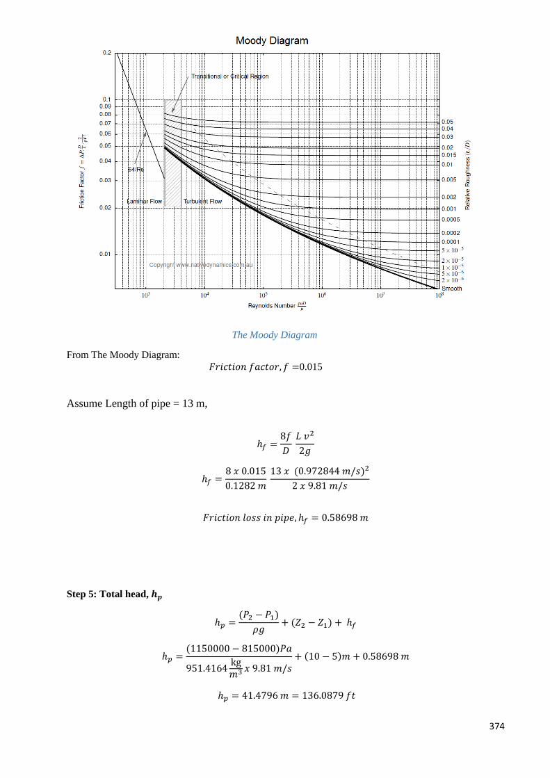
374
The Moody Diagram
From The Moody Diagram:
𝐹𝑟𝑖𝑐𝑡𝑖𝑜𝑛 𝑓𝑎𝑐𝑡𝑜𝑟, 𝑓 =0.015
Assume Length of pipe = 13 m,
ℎ𝑓 =8𝑓
𝐷 𝐿 𝑣2
2𝑔
ℎ𝑓 =8 𝑥 0.015
0.1282 𝑚 13 𝑥 (0.972844 𝑚/𝑠)2
2 𝑥 9.81 𝑚/𝑠
𝐹𝑟𝑖𝑐𝑡𝑖𝑜𝑛 𝑙𝑜𝑠𝑠 𝑖𝑛 𝑝𝑖𝑝𝑒, ℎ𝑓 = 0.58698 𝑚
Step 5: Total head, 𝒉𝒑
ℎ𝑝 =(𝑃2 − 𝑃1)
𝜌𝑔+ (𝑍2 − 𝑍1) + ℎ𝑓
ℎ𝑝 =(1150000 − 815000)𝑃𝑎
951.4164kg𝑚3 𝑥 9.81 𝑚/𝑠
+ (10 − 5)𝑚 + 0.58698 𝑚
ℎ𝑝 = 41.4796 𝑚 = 136.0879 𝑓𝑡
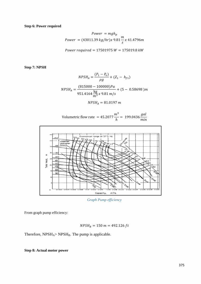
375
Step 6: Power required
𝑃𝑜𝑤𝑒𝑟 = 𝑚𝑔ℎ𝑝
𝑃𝑜𝑤𝑒𝑟 = (43011.39 𝑘𝑔/ℎ𝑟)𝑥 9.81𝑚
𝑠𝑥 41.4796𝑚
𝑃𝑜𝑤𝑒𝑟 𝑟𝑒𝑞𝑢𝑖𝑟𝑒𝑑 = 17501975 𝑊 = 175019.8 𝑘𝑊
Step 7: NPSH
𝑁𝑃𝑆𝐻𝐴 =(𝑃1 − 𝑃𝑣)
𝜌𝑔+ (𝑍1 − ℎ𝑓1)
𝑁𝑃𝑆𝐻𝐴 =(815000 − 100000)𝑃𝑎
951.4164kg𝑚3 𝑥 9.81 𝑚/𝑠
+ (5 − 0.58698 )𝑚
𝑁𝑃𝑆𝐻𝐴 = 81.0197 𝑚
Volumetric flow rate = 45.2077𝑚3
ℎ= 199.0436
𝑔𝑎𝑙
𝑚𝑖𝑛
Graph Pump efficiency
From graph pump efficiency:
𝑁𝑃𝑆𝐻𝑅 = 150 𝑚 = 492.126 𝑓𝑡
Therefore, NPSHA> NPSHR. The pump is applicable.
Step 8: Actual motor power
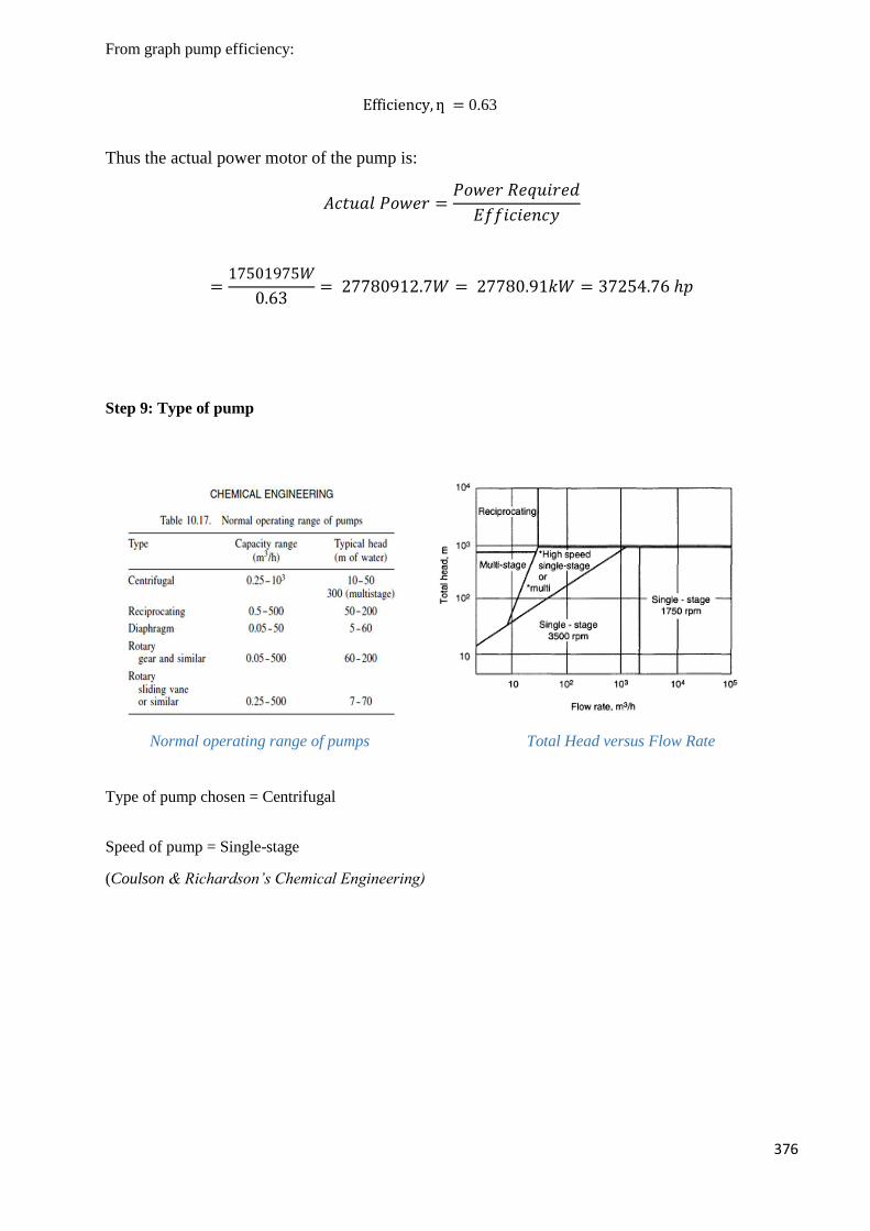
376
From graph pump efficiency:
Efficiency, ƞ = 0.63
Thus the actual power motor of the pump is:
𝐴𝑐𝑡𝑢𝑎𝑙 𝑃𝑜𝑤𝑒𝑟 =𝑃𝑜𝑤𝑒𝑟 𝑅𝑒𝑞𝑢𝑖𝑟𝑒𝑑
𝐸𝑓𝑓𝑖𝑐𝑖𝑒𝑛𝑐𝑦
=17501975𝑊
0.63= 27780912.7𝑊 = 27780.91𝑘𝑊 = 37254.76 ℎ𝑝
Step 9: Type of pump
Normal operating range of pumps Total Head versus Flow Rate
Type of pump chosen = Centrifugal
Speed of pump = Single-stage
(Coulson & Richardson’s Chemical Engineering)
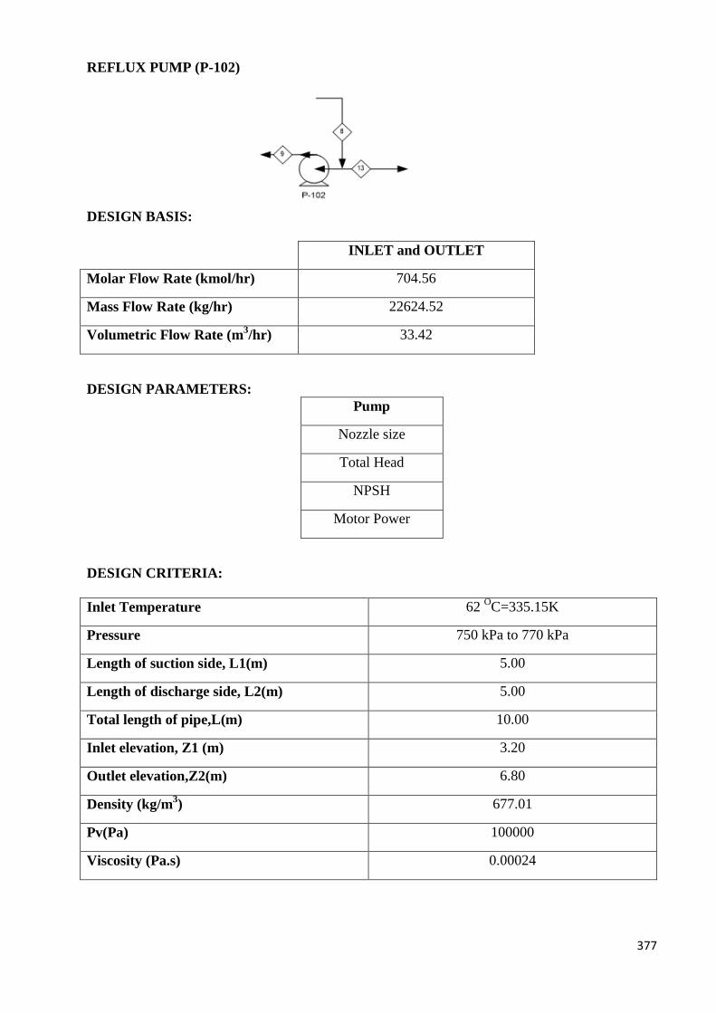
377
REFLUX PUMP (P-102)
DESIGN BASIS:
INLET and OUTLET
Molar Flow Rate (kmol/hr) 704.56
Mass Flow Rate (kg/hr) 22624.52
Volumetric Flow Rate (m3/hr) 33.42
DESIGN PARAMETERS:
Pump
Nozzle size
Total Head
NPSH
Motor Power
DESIGN CRITERIA:
Inlet Temperature 62 OC=335.15K
Pressure 750 kPa to 770 kPa
Length of suction side, L1(m) 5.00
Length of discharge side, L2(m) 5.00
Total length of pipe,L(m) 10.00
Inlet elevation, Z1 (m) 3.20
Outlet elevation,Z2(m) 6.80
Density (kg/m3) 677.01
Pv(Pa) 100000
Viscosity (Pa.s) 0.00024
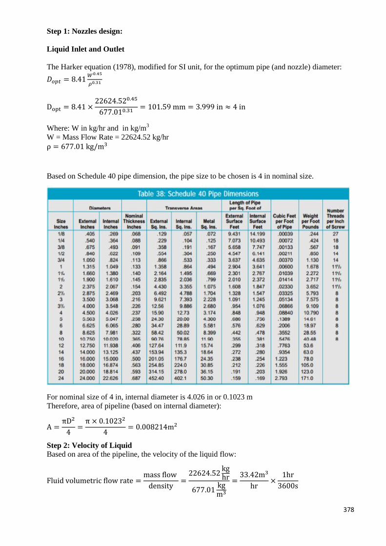
378
Step 1: Nozzles design:
Liquid Inlet and Outlet
The Harker equation (1978), modified for SI unit, for the optimum pipe (and nozzle) diameter:
𝐷𝑜𝑝𝑡 = 8.41𝑊0.45
𝜌0.31
Dopt = 8.41 ×22624.520.45
677.010.31= 101.59 mm = 3.999 in ≈ 4 in
Where: W in kg/hr and in kg/m3
W = Mass Flow Rate = 22624.52 kg/hr
ρ = 677.01 kg/m3
Based on Schedule 40 pipe dimension, the pipe size to be chosen is 4 in nominal size.
For nominal size of 4 in, internal diameter is 4.026 in or 0.1023 m
Therefore, area of pipeline (based on internal diameter):
A =πD2
4=
π × 0.10232
4= 0.008214m2
Step 2: Velocity of Liquid
Based on area of the pipeline, the velocity of the liquid flow:
Fluid volumetric flow rate =mass flow
density=
22624.52kghr
677.01kgm3
=33.42m3
hr×
1hr
3600s
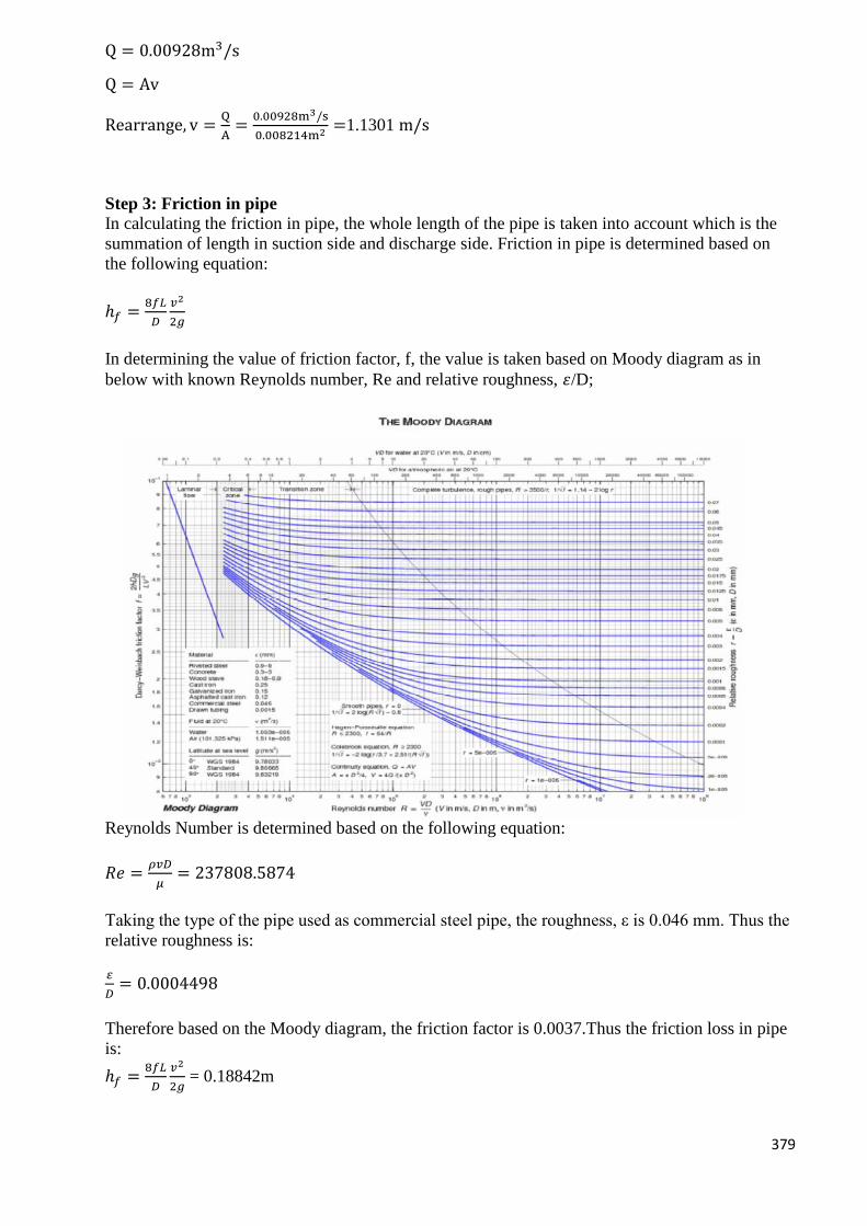
379
Q = 0.00928m3/s
Q = Av
Rearrange, v =Q
A=
0.00928m3/s
0.008214m2=1.1301 m/s
Step 3: Friction in pipe
In calculating the friction in pipe, the whole length of the pipe is taken into account which is the
summation of length in suction side and discharge side. Friction in pipe is determined based on
the following equation:
ℎ𝑓 =8𝑓𝐿
𝐷
𝑣2
2𝑔
In determining the value of friction factor, f, the value is taken based on Moody diagram as in
below with known Reynolds number, Re and relative roughness, 𝜀/D;
Reynolds Number is determined based on the following equation:
𝑅𝑒 =𝜌𝑣𝐷
𝜇= 237808.5874
Taking the type of the pipe used as commercial steel pipe, the roughness, ε is 0.046 mm. Thus the
relative roughness is:
𝜀
𝐷= 0.0004498
Therefore based on the Moody diagram, the friction factor is 0.0037.Thus the friction loss in pipe
is:
ℎ𝑓 =8𝑓𝐿
𝐷
𝑣2
2𝑔 = 0.18842m
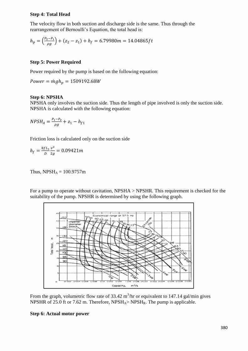
380
Step 4: Total Head
The velocity flow in both suction and discharge side is the same. Thus through the
rearrangement of Bernoulli’s Equation, the total head is:
ℎ𝑝 = (𝑃2−𝑃1
𝜌𝑔) + (𝑧2 − 𝑧1) + ℎ𝑓 = 6.79980𝑚 = 14.04865𝑓𝑡
Step 5: Power Required
Power required by the pump is based on the following equation:
𝑃𝑜𝑤𝑒𝑟 = �̇�𝑔ℎ𝑝 = 1509192.68𝑊
Step 6: NPSHA
NPSHA only involves the suction side. Thus the length of pipe involved is only the suction side.
NPSHA is calculated with the following equation:
𝑁𝑃𝑆𝐻𝐴 =𝑃1−𝑃𝑣
𝜌𝑔+ 𝑧1 − ℎ𝑓1
Friction loss is calculated only on the suction side
ℎ𝑓 =8𝑓𝐿1
𝐷
𝑣2
2𝑔= 0.09421𝑚
Thus, NPSHA = 100.9757m
For a pump to operate without cavitation, NPSHA > NPSHR. This requirement is checked for the
suitability of the pump. NPSHR is determined by using the following graph.
From the graph, volumetric flow rate of 33.42 m3/hr or equivalent to 147.14 gal/min gives
NPSHR of 25.0 ft or 7.62 m. Therefore, NPSHA> NPSHR. The pump is applicable.
Step 6: Actual motor power
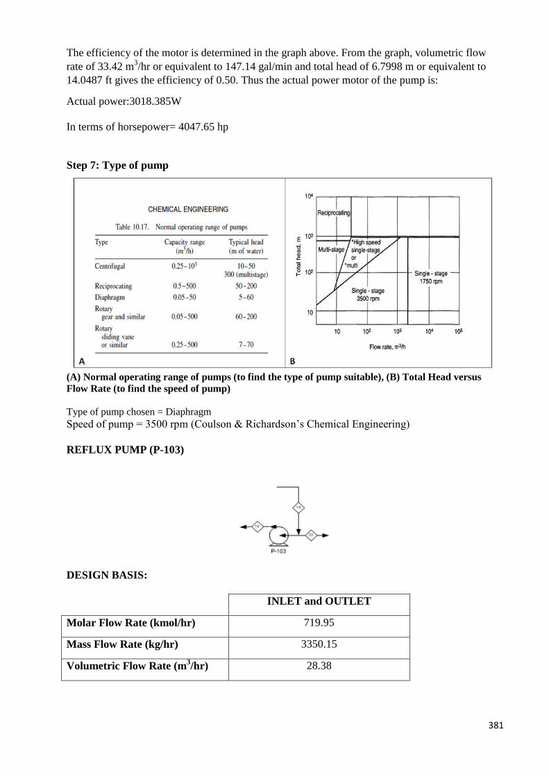
381
The efficiency of the motor is determined in the graph above. From the graph, volumetric flow
rate of 33.42 m3/hr or equivalent to 147.14 gal/min and total head of 6.7998 m or equivalent to
14.0487 ft gives the efficiency of 0.50. Thus the actual power motor of the pump is:
Actual power:3018.385W
In terms of horsepower= 4047.65 hp
Step 7: Type of pump
(A) Normal operating range of pumps (to find the type of pump suitable), (B) Total Head versus
Flow Rate (to find the speed of pump)
Type of pump chosen = Diaphragm Speed of pump = 3500 rpm (Coulson & Richardson’s Chemical Engineering)
REFLUX PUMP (P-103)
DESIGN BASIS:
INLET and OUTLET
Molar Flow Rate (kmol/hr) 719.95
Mass Flow Rate (kg/hr) 3350.15
Volumetric Flow Rate (m3/hr) 28.38
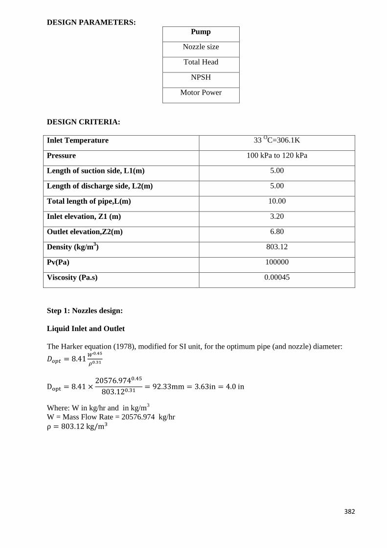
382
DESIGN PARAMETERS:
Pump
Nozzle size
Total Head
NPSH
Motor Power
DESIGN CRITERIA:
Inlet Temperature 33 OC=306.1K
Pressure 100 kPa to 120 kPa
Length of suction side, L1(m) 5.00
Length of discharge side, L2(m) 5.00
Total length of pipe,L(m) 10.00
Inlet elevation, Z1 (m) 3.20
Outlet elevation,Z2(m) 6.80
Density (kg/m3) 803.12
Pv(Pa) 100000
Viscosity (Pa.s) 0.00045
Step 1: Nozzles design:
Liquid Inlet and Outlet
The Harker equation (1978), modified for SI unit, for the optimum pipe (and nozzle) diameter:
𝐷𝑜𝑝𝑡 = 8.41𝑊0.45
𝜌0.31
Dopt = 8.41 ×20576.9740.45
803.120.31= 92.33mm = 3.63in = 4.0 in
Where: W in kg/hr and in kg/m3
W = Mass Flow Rate = 20576.974 kg/hr
ρ = 803.12 kg/m3

383
Based on Schedule 40 pipe dimension, the pipe size to be chosen is 4 in nominal size.
For nominal size of 4 in, internal diameter is 4.026 in or 0.1022 m
Therefore, area of pipeline (based on internal diameter):
A =πD2
4=
π×0.10222
4=0.1023 m2
Step 2: Velocity of Liquid
Based on area of the pipeline, the velocity of the liquid flow:
Fluid volumetric flow rate =mass flow
density=
20576.974kghr
803.12kgm3
=25.62m3
hr×
1hr
3600s
Q = 0.00712m3/s
Q = Av
Rearrange, v =Q
A=
0.00712m3/s
0.0082 𝑚2=0.866 m/s
Step 3: Friction in pipe
In calculating the friction in pipe, the whole length of the pipe is taken into account which is the
summation of length in suction side and discharge side. Friction in pipe is determined based on
the following equation:
ℎ𝑓 =8𝑓𝐿
𝐷
𝑣2
2𝑔
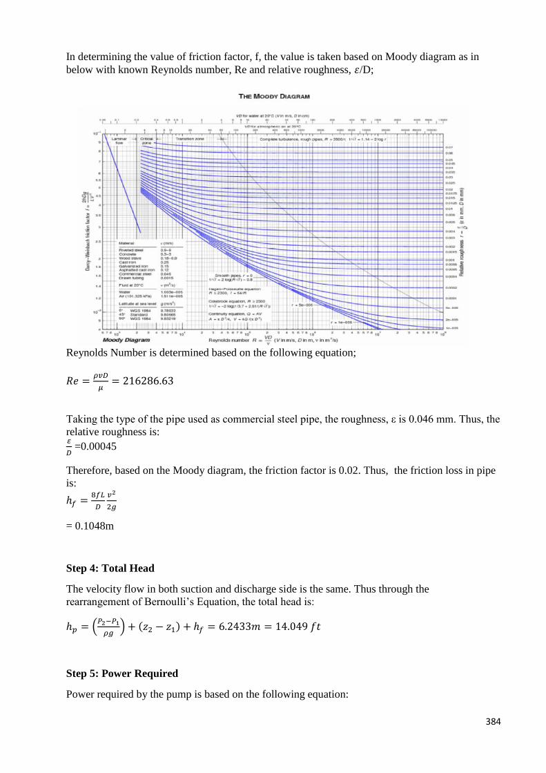
384
In determining the value of friction factor, f, the value is taken based on Moody diagram as in
below with known Reynolds number, Re and relative roughness, 𝜀/D;
Reynolds Number is determined based on the following equation;
𝑅𝑒 =𝜌𝑣𝐷
𝜇= 216286.63
Taking the type of the pipe used as commercial steel pipe, the roughness, ε is 0.046 mm. Thus, the
relative roughness is: 𝜀
𝐷 =0.00045
Therefore, based on the Moody diagram, the friction factor is 0.02. Thus, the friction loss in pipe
is:
ℎ𝑓 =8𝑓𝐿
𝐷
𝑣2
2𝑔
= 0.1048m
Step 4: Total Head
The velocity flow in both suction and discharge side is the same. Thus through the
rearrangement of Bernoulli’s Equation, the total head is:
ℎ𝑝 = (𝑃2−𝑃1
𝜌𝑔) + (𝑧2 − 𝑧1) + ℎ𝑓 = 6.2433𝑚 = 14.049 𝑓𝑡
Step 5: Power Required
Power required by the pump is based on the following equation:
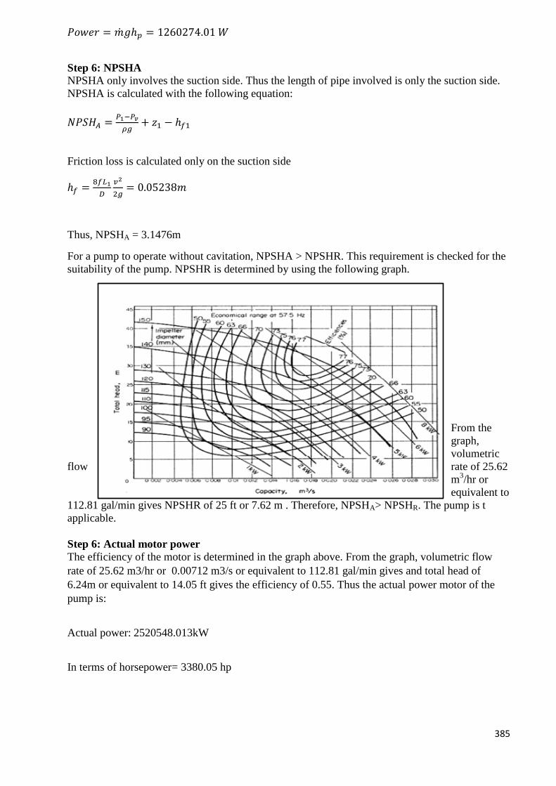
385
𝑃𝑜𝑤𝑒𝑟 = �̇�𝑔ℎ𝑝 = 1260274.01 𝑊
Step 6: NPSHA
NPSHA only involves the suction side. Thus the length of pipe involved is only the suction side.
NPSHA is calculated with the following equation:
𝑁𝑃𝑆𝐻𝐴 =𝑃1−𝑃𝑣
𝜌𝑔+ 𝑧1 − ℎ𝑓1
Friction loss is calculated only on the suction side
ℎ𝑓 =8𝑓𝐿1
𝐷
𝑣2
2𝑔= 0.05238𝑚
Thus, NPSHA = 3.1476m
For a pump to operate without cavitation, NPSHA > NPSHR. This requirement is checked for the
suitability of the pump. NPSHR is determined by using the following graph.
From the
graph,
volumetric
flow rate of 25.62
m3/hr or
equivalent to
112.81 gal/min gives NPSHR of 25 ft or 7.62 m . Therefore, NPSHA> NPSHR. The pump is t
applicable.
Step 6: Actual motor power
The efficiency of the motor is determined in the graph above. From the graph, volumetric flow
rate of 25.62 m3/hr or 0.00712 m3/s or equivalent to 112.81 gal/min gives and total head of
6.24m or equivalent to 14.05 ft gives the efficiency of 0.55. Thus the actual power motor of the
pump is:
Actual power: 2520548.013kW
In terms of horsepower= 3380.05 hp
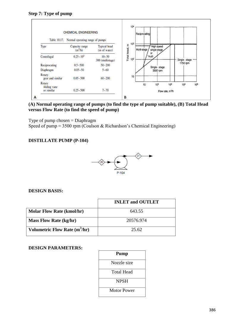
386
Step 7: Type of pump
(A) Normal operating range of pumps (to find the type of pump suitable), (B) Total Head
versus Flow Rate (to find the speed of pump)
Type of pump chosen = Diaphragm
Speed of pump = 3500 rpm (Coulson & Richardson’s Chemical Engineering)
DISTILLATE PUMP (P-104)
DESIGN BASIS:
INLET and OUTLET
Molar Flow Rate (kmol/hr) 643.55
Mass Flow Rate (kg/hr) 20576.974
Volumetric Flow Rate (m3/hr) 25.62
DESIGN PARAMETERS:
Pump
Nozzle size
Total Head
NPSH
Motor Power
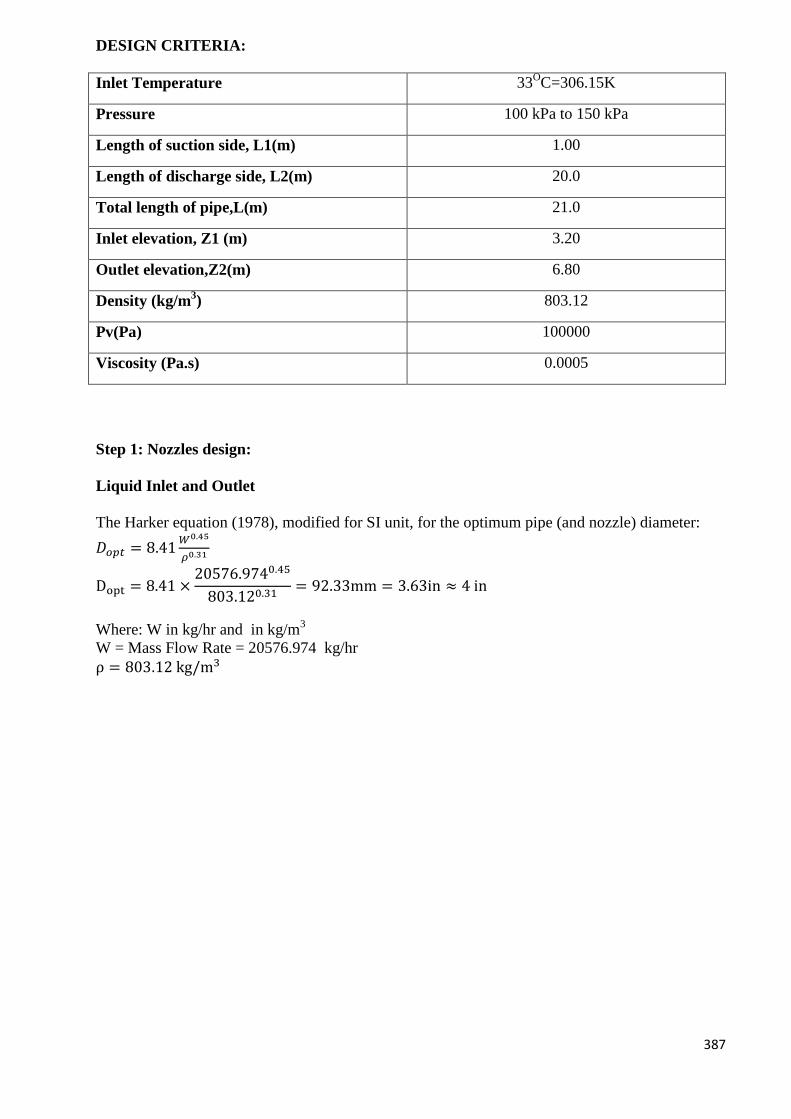
387
DESIGN CRITERIA:
Inlet Temperature 33OC=306.15K
Pressure 100 kPa to 150 kPa
Length of suction side, L1(m) 1.00
Length of discharge side, L2(m) 20.0
Total length of pipe,L(m) 21.0
Inlet elevation, Z1 (m) 3.20
Outlet elevation,Z2(m) 6.80
Density (kg/m3) 803.12
Pv(Pa) 100000
Viscosity (Pa.s) 0.0005
Step 1: Nozzles design:
Liquid Inlet and Outlet
The Harker equation (1978), modified for SI unit, for the optimum pipe (and nozzle) diameter:
𝐷𝑜𝑝𝑡 = 8.41𝑊0.45
𝜌0.31
Dopt = 8.41 ×20576.9740.45
803.120.31= 92.33mm = 3.63in ≈ 4 in
Where: W in kg/hr and in kg/m3
W = Mass Flow Rate = 20576.974 kg/hr
ρ = 803.12 kg/m3
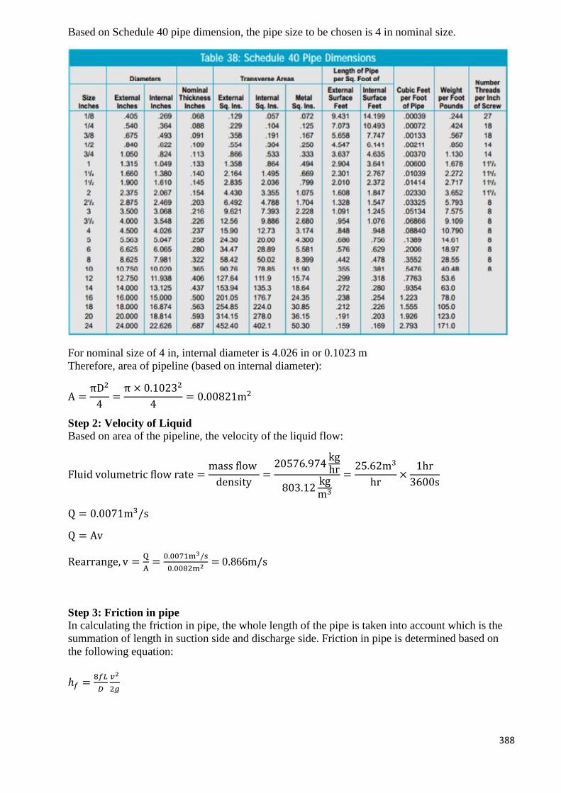
388
Based on Schedule 40 pipe dimension, the pipe size to be chosen is 4 in nominal size.
For nominal size of 4 in, internal diameter is 4.026 in or 0.1023 m
Therefore, area of pipeline (based on internal diameter):
A =πD2
4=
π × 0.10232
4= 0.00821m2
Step 2: Velocity of Liquid
Based on area of the pipeline, the velocity of the liquid flow:
Fluid volumetric flow rate =mass flow
density=
20576.974kghr
803.12kgm3
=25.62m3
hr×
1hr
3600s
Q = 0.0071m3/s
Q = Av
Rearrange, v =Q
A=
0.0071m3/s
0.0082m2= 0.866m/s
Step 3: Friction in pipe
In calculating the friction in pipe, the whole length of the pipe is taken into account which is the
summation of length in suction side and discharge side. Friction in pipe is determined based on
the following equation:
ℎ𝑓 =8𝑓𝐿
𝐷
𝑣2
2𝑔
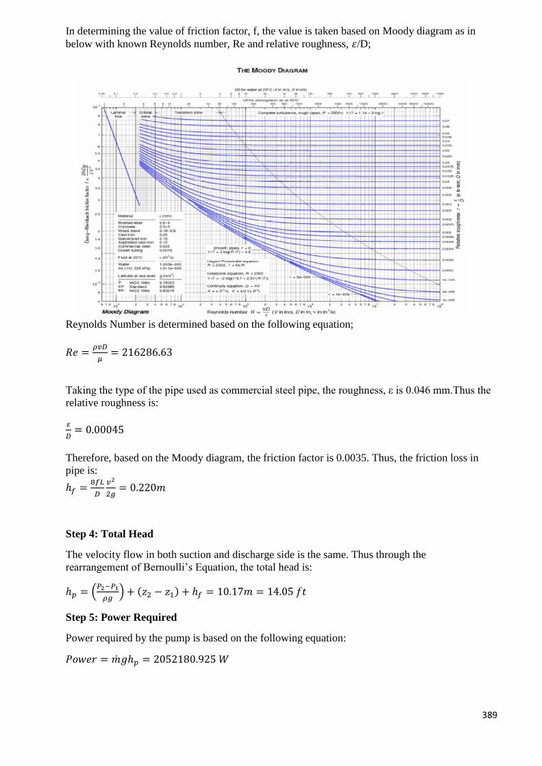
389
In determining the value of friction factor, f, the value is taken based on Moody diagram as in
below with known Reynolds number, Re and relative roughness, 𝜀/D;
Reynolds Number is determined based on the following equation;
𝑅𝑒 =𝜌𝑣𝐷
𝜇= 216286.63
Taking the type of the pipe used as commercial steel pipe, the roughness, ε is 0.046 mm.Thus the
relative roughness is:
𝜀
𝐷= 0.00045
Therefore, based on the Moody diagram, the friction factor is 0.0035. Thus, the friction loss in
pipe is:
ℎ𝑓 =8𝑓𝐿
𝐷
𝑣2
2𝑔= 0.220𝑚
Step 4: Total Head
The velocity flow in both suction and discharge side is the same. Thus through the
rearrangement of Bernoulli’s Equation, the total head is:
ℎ𝑝 = (𝑃2−𝑃1
𝜌𝑔) + (𝑧2 − 𝑧1) + ℎ𝑓 = 10.17𝑚 = 14.05 𝑓𝑡
Step 5: Power Required
Power required by the pump is based on the following equation:
𝑃𝑜𝑤𝑒𝑟 = �̇�𝑔ℎ𝑝 = 2052180.925 𝑊
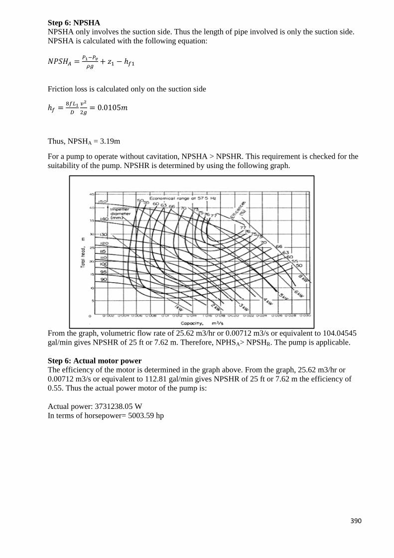
390
Step 6: NPSHA
NPSHA only involves the suction side. Thus the length of pipe involved is only the suction side.
NPSHA is calculated with the following equation:
𝑁𝑃𝑆𝐻𝐴 =𝑃1−𝑃𝑣
𝜌𝑔+ 𝑧1 − ℎ𝑓1
Friction loss is calculated only on the suction side
ℎ𝑓 =8𝑓𝐿1
𝐷
𝑣2
2𝑔= 0.0105𝑚
Thus, NPSHA = 3.19m
For a pump to operate without cavitation, NPSHA > NPSHR. This requirement is checked for the
suitability of the pump. NPSHR is determined by using the following graph.
From the graph, volumetric flow rate of 25.62 m3/hr or 0.00712 m3/s or equivalent to 104.04545
gal/min gives NPSHR of 25 ft or 7.62 m. Therefore, NPHSA> NPSHR. The pump is applicable.
Step 6: Actual motor power
The efficiency of the motor is determined in the graph above. From the graph, 25.62 m3/hr or
0.00712 m3/s or equivalent to 112.81 gal/min gives NPSHR of 25 ft or 7.62 m the efficiency of
0.55. Thus the actual power motor of the pump is:
Actual power: 3731238.05 W
In terms of horsepower= 5003.59 hp
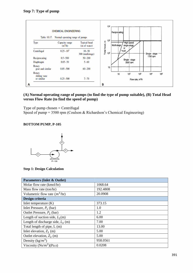
391
Step 7: Type of pump
(A) Normal operating range of pumps (to find the type of pump suitable), (B) Total Head
versus Flow Rate (to find the speed of pump)
Type of pump chosen = Centrifugal
Speed of pump = 3500 rpm (Coulson & Richardson’s Chemical Engineering)
BOTTOM PUMP, P-105
Step 1: Design Calculation
Parameters (Inlet & Outlet)
Molar flow rate (kmol/hr) 1068.64
Mass flow rate (ton/hr) 192.4808
Volumetric flow rate (𝑚3/hr) 20.0908
Design criteria
Inlet temperature (K) 373.15
Inlet Pressure, 𝑃1 (bar) 1.0
Outlet Pressure, 𝑃2 (bar) 1.2
Length of suction side, 𝐿1(m) 6.00
Length of discharge side, 𝐿2 (m) 7.00
Total length of pipe, L (m) 13.00
Inlet elevation, 𝑍1 (m) 5.00
Outlet elevation, 𝑍2 (m) 5.00
Density (kg/𝑚3) 958.0561
Viscosity (Ns/𝑚2)(Pa.s) 0.0208
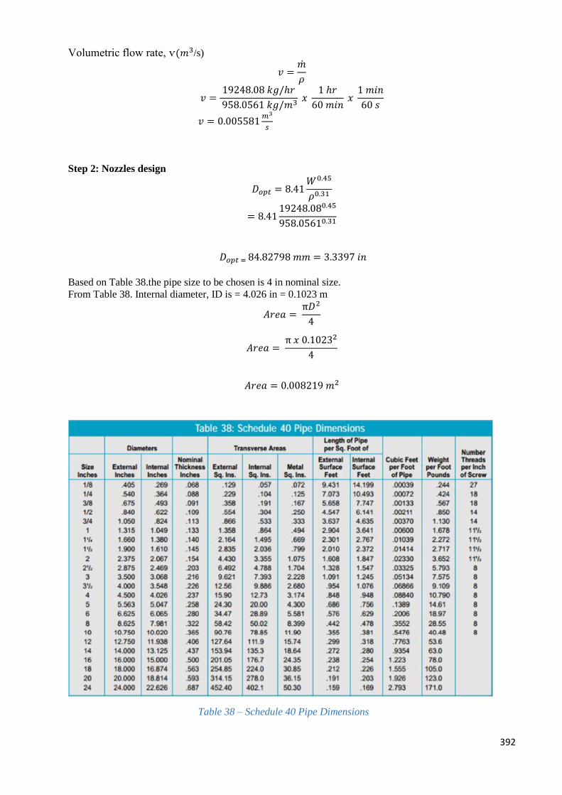
392
Volumetric flow rate, ѵ(𝑚3/s)
𝑣 =�̇�
𝜌
𝑣 =19248.08 𝑘𝑔/ℎ𝑟
958.0561 𝑘𝑔/𝑚3 𝑥
1 ℎ𝑟
60 𝑚𝑖𝑛 𝑥
1 𝑚𝑖𝑛
60 𝑠
𝑣 = 0.005581𝑚3
𝑠
Step 2: Nozzles design
𝐷𝑜𝑝𝑡 = 8.41𝑊0.45
𝜌0.31
= 8.4119248.080.45
958.05610.31
𝐷𝑜𝑝𝑡 = 84.82798 𝑚𝑚 = 3.3397 𝑖𝑛
Based on Table 38.the pipe size to be chosen is 4 in nominal size.
From Table 38. Internal diameter, ID is = 4.026 in = 0.1023 m
𝐴𝑟𝑒𝑎 = π𝐷2
4
𝐴𝑟𝑒𝑎 = π 𝑥 0.10232
4
𝐴𝑟𝑒𝑎 = 0.008219 𝑚2
Table 38 – Schedule 40 Pipe Dimensions
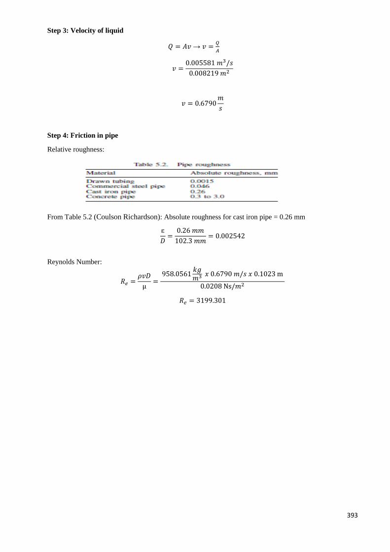
393
Step 3: Velocity of liquid
𝑄 = 𝐴𝑣 → 𝑣 =𝑄
𝐴
𝑣 =0.005581 𝑚3/𝑠
0.008219 𝑚2
𝑣 = 0.6790𝑚
𝑠
Step 4: Friction in pipe
Relative roughness:
From Table 5.2 (Coulson Richardson): Absolute roughness for cast iron pipe = 0.26 mm
ɛ
𝐷=
0.26 𝑚𝑚
102.3 𝑚𝑚= 0.002542
Reynolds Number:
𝑅𝑒 =𝜌𝑣𝐷
µ=
958.0561𝑘𝑔𝑚3 𝑥 0.6790 𝑚/𝑠 𝑥 0.1023 m
0.0208 Ns/𝑚2
𝑅𝑒 = 3199.301
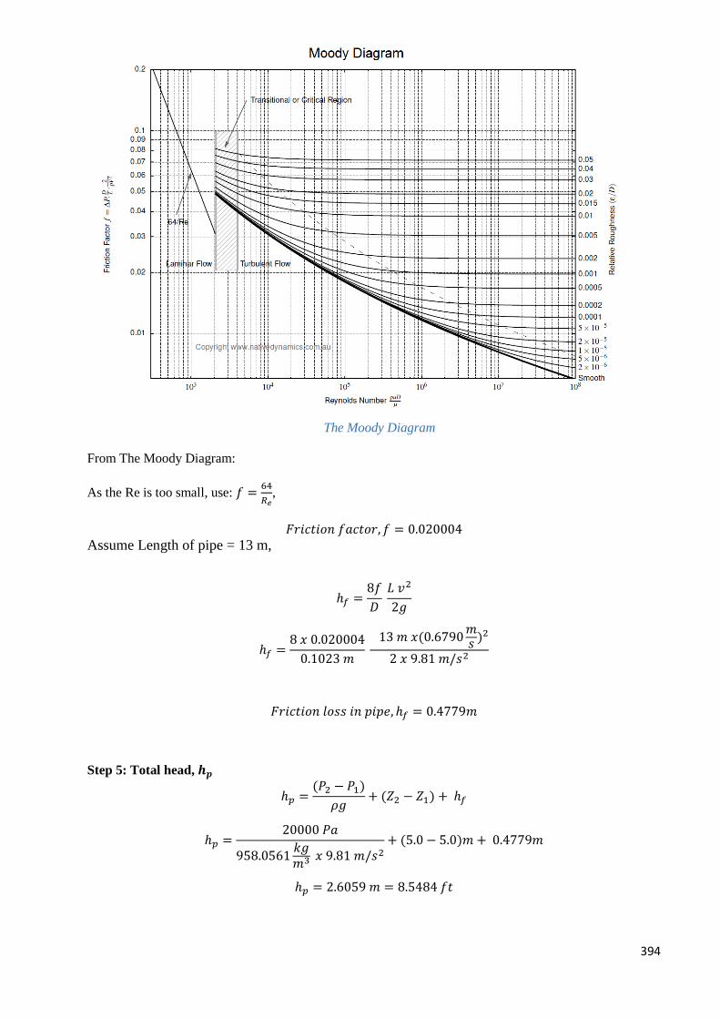
394
The Moody Diagram
From The Moody Diagram:
As the Re is too small, use: 𝑓 =64
𝑅𝑒,
𝐹𝑟𝑖𝑐𝑡𝑖𝑜𝑛 𝑓𝑎𝑐𝑡𝑜𝑟, 𝑓 = 0.020004
Assume Length of pipe = 13 m,
ℎ𝑓 =8𝑓
𝐷 𝐿 𝑣2
2𝑔
ℎ𝑓 =8 𝑥 0.020004
0.1023 𝑚 13 𝑚 𝑥(0.6790
𝑚𝑠 )2
2 𝑥 9.81 𝑚/𝑠2
𝐹𝑟𝑖𝑐𝑡𝑖𝑜𝑛 𝑙𝑜𝑠𝑠 𝑖𝑛 𝑝𝑖𝑝𝑒, ℎ𝑓 = 0.4779𝑚
Step 5: Total head, 𝒉𝒑
ℎ𝑝 =(𝑃2 − 𝑃1)
𝜌𝑔+ (𝑍2 − 𝑍1) + ℎ𝑓
ℎ𝑝 =20000 𝑃𝑎
958.0561𝑘𝑔𝑚3 𝑥 9.81 𝑚/𝑠2
+ (5.0 − 5.0)𝑚 + 0.4779𝑚
ℎ𝑝 = 2.6059 𝑚 = 8.5484 𝑓𝑡
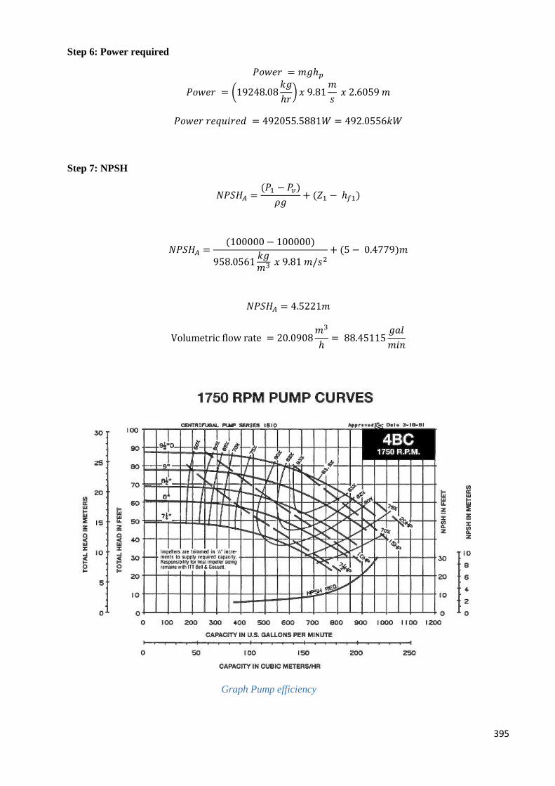
395
Step 6: Power required
𝑃𝑜𝑤𝑒𝑟 = 𝑚𝑔ℎ𝑝
𝑃𝑜𝑤𝑒𝑟 = (19248.08𝑘𝑔
ℎ𝑟) 𝑥 9.81
𝑚
𝑠 𝑥 2.6059 𝑚
𝑃𝑜𝑤𝑒𝑟 𝑟𝑒𝑞𝑢𝑖𝑟𝑒𝑑 = 492055.5881𝑊 = 492.0556𝑘𝑊
Step 7: NPSH
𝑁𝑃𝑆𝐻𝐴 =(𝑃1 − 𝑃𝑣)
𝜌𝑔+ (𝑍1 − ℎ𝑓1)
𝑁𝑃𝑆𝐻𝐴 =(100000 − 100000)
958.0561𝑘𝑔𝑚3 𝑥 9.81 𝑚/𝑠2
+ (5 − 0.4779)𝑚
𝑁𝑃𝑆𝐻𝐴 = 4.5221𝑚
Volumetric flow rate = 20.0908𝑚3
ℎ= 88.45115
𝑔𝑎𝑙
𝑚𝑖𝑛
Graph Pump efficiency
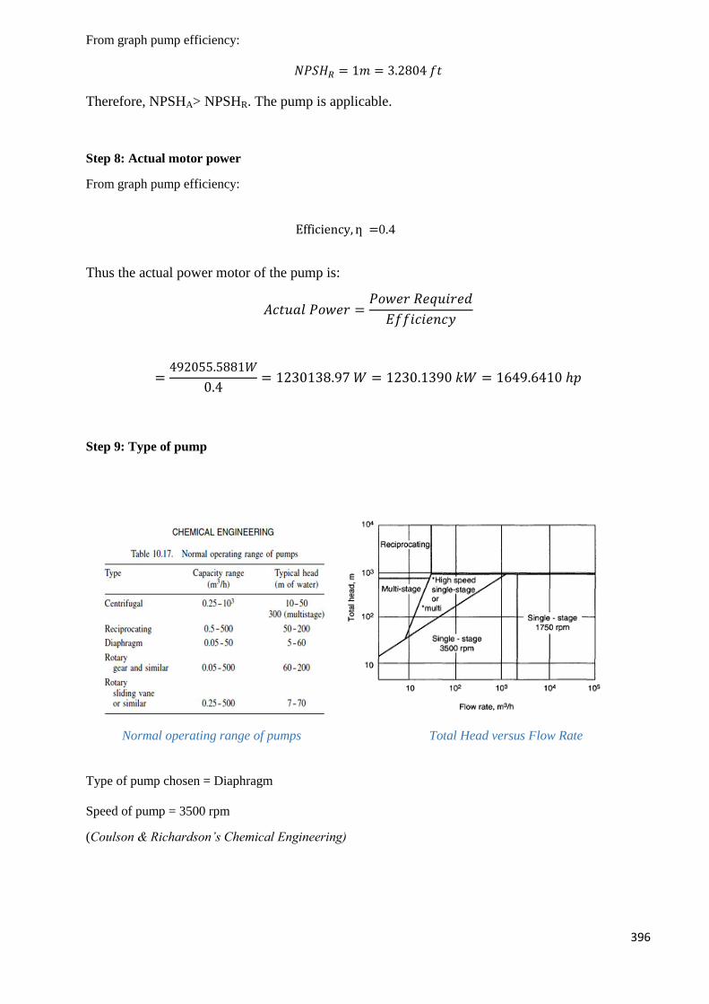
396
From graph pump efficiency:
𝑁𝑃𝑆𝐻𝑅 = 1𝑚 = 3.2804 𝑓𝑡
Therefore, NPSHA> NPSHR. The pump is applicable.
Step 8: Actual motor power
From graph pump efficiency:
Efficiency, ƞ =0.4
Thus the actual power motor of the pump is:
𝐴𝑐𝑡𝑢𝑎𝑙 𝑃𝑜𝑤𝑒𝑟 =𝑃𝑜𝑤𝑒𝑟 𝑅𝑒𝑞𝑢𝑖𝑟𝑒𝑑
𝐸𝑓𝑓𝑖𝑐𝑖𝑒𝑛𝑐𝑦
=492055.5881𝑊
0.4= 1230138.97 𝑊 = 1230.1390 𝑘𝑊 = 1649.6410 ℎ𝑝
Step 9: Type of pump
Normal operating range of pumps Total Head versus Flow Rate
Type of pump chosen = Diaphragm
Speed of pump = 3500 rpm
(Coulson & Richardson’s Chemical Engineering)
397
MINUTE MEETINGS (1)
Date: 17th
November 2015 (Tuesday)
Time: 9.00pm – 11.00pm
Venue: Cafe Lembaran
Attendance:
1. Syed Zulfadli Syed Putra
2. Nurul Ezati Bt Mat Sidek
3. Syafiqah Binti Mad Zin
4. Elaine Ooi Chin Wen
5. Soon Kah Aik
Agenda:
1. First of all, we discuss and try to understand about the task 3 given by lecturer.
2. We start to distribute part of the task which mainly on the design of unit operations that
involves in our plant design which are reactor, distillation column, absorber, heater,
reboiler, condenser and pump.
3. Set the date for our next group meeting.
Prepared by,
………………………….
(Syed Zulfadli Syed Putra)
398
MINUTE OF MEETINGS (2)
Date: 23th
November 2015 (Monday)
Time: 4.00 pm – 5.15pm
Venue: Anjung Ilmu in School of Chemical Engineering
Attendance:
1. Syed Zulfadli Syed Putra
2. Nurul Ezati Bt Mat Sidek
3. Syafiqah Binti Mad Zin
4. Elaine Ooi Chin Wen
5. Soon Kah Aik
Agenda:
1. Discuss on what we understand on the design of each unit operations.
2. Report any potential problems that will encounter when doing the design later.
3. Plan to meet our supervisor to discuss on effective ways to solve the potential problems.
4. We identified that we need to do mechanical design for all mass and energy transfer equipment.
Since, it is quite similar, we must go back and study then share with each other on next coming
meeting.
Prepared by,
………………………….
(Nurul Ezati Bt Mat Sidek)
399
MINUTE MEETINGS WITH SUPERVISOR (3)
Date :30th
November 2015 (Monday)
Time :3.00 pm – 5.00pm
Venue: Lecturer’s Office in School of Chemical Engineering
Attendance:
1. Prof.Madya Dr. Norashid Aziz
2. Syed Zulfadli Syed Putra
3. Nurul Ezati Bt Mat Sidek
4. Syafiqah Binti Mad Zin
5. Elaine Ooi Chin Wen
6. Soon Kah Aik
Agenda:
1. We had asked Dr that is there any problem in our Task 2 because it will determine whether
we are going to continue our job in Task 3.
2. All the designed unit operations must come out with logic and appropriate scale so that they
are practically/feasible to install in industry.
3. Dr ask us to try our best to design and understand on the design method, perhaps it is useful
in our career in the future.
Prepared by,
………………………….
(Syafiqah Binti Mad Zin)
400
MINUTES OF MEETING (4)
Date : 7th
December 2015 (Monday)
Time: 9.30 pm –11.00 pm
Venue: Cafe Lembaran
Attendance:
1. Syed Zulfadli Syed Putra
2. Nurul Ezati Bt Mat Sidek
3. Syafiqah Binti Mad Zin
4. Elaine Ooi Chin Wen
5. Soon Kah Aik
Agenda:
1. Beginning of the meeting, we review back what we have done so far to check for any
correction or modification of the works.
2. Meantime, we do all the design in spreadsheet (EXCEL) by key in all the important
formula so that will ease our calculation next time.
3. After that, we had continued with our discussion on the mechanical part for every unit
operations.
4. We will discuss with each other immediately through social networking when we face any
problem when doing it.’
5. Start to do the compilation for task 1 and task 2 so that we won’t are able to
complete/submit the final report on time.
6. Plan to meet dr again to update our progression.
Prepared by;
-------------------------
(Elaine Ooi Chin Wen)
401
MINUTES OF MEETING (5)
Date :11th
October 2015 (Friday)
Time: 3.00 pm –4.30 pm
Venue: Café lembaran
Attendance:
1. Syed Zulfadli Syed Putra
2. Nurul Ezati Bt Mat Sidek
3. Syafiqah Binti Mad Zin
4. Elaine Ooi Chin Wen
5. Soon Kah Aik
Agenda:
1. Since dr are busy, so we couldn’t make the las meeting together with dr in his room.
2. Start to do all the compilation.
3. Help those who still not complete their task.
Prepared by;
-------------------------
(Soon Kah Aik)


