
®
725 Multifunction Process Calibrator
PN 1549644 English January 2000 Rev.2, 8/05 © 2000-2005 Fluke Corporation. All rights reserved. Printed in USA All product names are trademarks of their respective companies.
Product Overview

LIMITED WARRANTY AND LIMITATION OF LIABILITY
Each Fluke product is warranted to be free from defects in material and workmanship under normal use and service. The warranty period is three years andbegins on the date of shipment. Parts, product repairs, and services are warranted for 90 days. This warranty extends only to the original buyer or end-usercustomer of a Fluke authorized reseller, and does not apply to fuses, disposable batteries, or to any product which, in Fluke’s opinion, has been misused, al-tered, neglected, contaminated, or damaged by accident or abnormal conditions of operation or handling. Fluke warrants that software will operate substantiallyin accordance with its functional specifications for 90 days and that it has been properly recorded on non-defective media. Fluke does not warrant that softwarewill be error free or operate without interruption.
Fluke authorized resellers shall extend this warranty on new and unused products to end-user customers only but have no authority to extend a greater or differ-ent warranty on behalf of Fluke. Warranty support is available only if product is purchased through a Fluke authorized sales outlet or Buyer has paid the applica-ble international price. Fluke reserves the right to invoice Buyer for importation costs of repair/replacement parts when product purchased in one country is sub-mitted for repair in another country.
Fluke’s warranty obligation is limited, at Fluke’s option, to refund of the purchase price, free of charge repair, or replacement of a defective product which isreturned to a Fluke authorized service center within the warranty period.To obtain warranty service, contact your nearest Fluke authorized service center to obtain return authorization information, then send the product to that servicecenter, with a description of the difficulty, postage and insurance prepaid (FOB Destination). Fluke assumes no risk for damage in transit. Following warrantyrepair, the product will be returned to Buyer, transportation prepaid (FOB Destination). If Fluke determines that failure was caused by neglect, misuse, contami-nation, alteration, accident, or abnormal condition of operation or handling, including overvoltage failures caused by use outside the product’s specified rating, ornormal wear and tear of mechanical components, Fluke will provide an estimate of repair costs and obtain authorization before commencing the work. Followingrepair, the product will be returned to the Buyer transportation prepaid and the Buyer will be billed for the repair and return transportation charges (FOB ShippingPoint).
THIS WARRANTY IS BUYER'S SOLE AND EXCLUSIVE REMEDY AND IS IN LIEU OF ALL OTHER WARRANTIES, EXPRESS OR IMPLIED, INCLUDINGBUT NOT LIMITED TO ANY IMPLIED WARRANTY OF MERCHANTABILITY OR FITNESS FOR A PARTICULAR PURPOSE. FLUKE SHALL NOT BE LIABLEFOR ANY SPECIAL, INDIRECT, INCIDENTAL OR CONSEQUENTIAL DAMAGES OR LOSSES, INCLUDING LOSS OF DATA, ARISING FROM ANY CAUSEOR THEORY.
Since some countries or states do not allow limitation of the term of an implied warranty, or exclusion or limitation of incidental or consequential damages, thelimitations and exclusions of this warranty may not apply to every buyer. If any provision of this Warranty is held invalid or unenforceable by a court or otherdecision-maker of competent jurisdiction, such holding will not affect the validity or enforceability of any other provision.
Fluke CorporationP.O. Box 9090Everett, WA 98206-9090U.S.A.
Fluke Europe B.V.P.O. Box 11865602 BD EindhovenThe Netherlands
11/99
1
Multifunction Process Calibrator
IntroductionYour Fluke 725 Multifunction Process Calibrator (referredto as “the calibrator”) is a handheld, battery-operatedinstrument that measures and sources electrical andphysical parameters.
The calibrator has the following features and functions:
• A split-screen display. The upper display allows youto measure volts, current, and pressure only. Thelower display allows you to measure and sourcevolts, current, pressure, resistance temperaturedetectors, thermocouples, frequency, and ohms.
• Calibrates a transmitter using the split-screen.• A thermocouple (TC) input/output terminal and
internal isothermal block with automatic reference-junction temperature compensation.
• Stores and recalls setups.• Manual stepping and automatic stepping and
ramping.
• Controls the calibrator remotely from a PC running aterminal emulator program.
Accessing the Users ManualThe 725 Users Manual is available on the 725 CDincluded with your calibrator.
Contacting FlukeTo order accessories, receive operating assistance, orget the location of the nearest Fluke distributor or ServiceCenter, call:
USA: 1-888-99-FLUKE (1-888-993-5853)Canada: 1-800-36-FLUKE (1-800-363-5853)Europe: +31 402-675-200Japan: +81-3-3434-0181Singapore: +65-738-5655Anywhere in the world: +1-425-446-5500
Or, visit Fluke's Web site at www.fluke.com.

725Product Overview
2
Standard EquipmentThe items listed below are included with your calibrator. Ifthe calibrator is damaged or something is missing,contact the place of purchase immediately. To orderreplacement parts or spares, see the user-replaceableparts list in Table 4.
• TL75 test leads (one set)
• AC72 alligator clips (one set)
• Stackable alligator clip test leads (one set)
• 725 Product Overview Manual
• 725 CD-ROM (contains Users Manual)
• Spare fuse
Safety InformationThe calibrator is designed in accordance with IEC1010-1,ANSI/ISA S82.01-1994 and CAN/CSA C22.2 No. 1010.1-92. Use the calibrator only as specified in this manual,otherwise the protection provided by the calibrator maybe impaired.
A Warning identifies conditions and actions that posehazard(s) to the user; a Caution identifies conditions andactions that may damage the calibrator or the equipmentunder test.
International symbols used on the calibrator and in thismanual are explained in Table 1.
WarningTo avoid possible electric shock or personal injury:• Do not apply more than the rated voltage, as marked on the calibrator, between the terminals, or between
any terminal and earth ground (30 V 24 mA max all terminals).• Before each use, verify the calibrator’s operation by measuring a known voltage.• Follow all equipment safety procedures.• Never touch the probe to a voltage source when the test leads are plugged into the current terminals.• Do not use the calibrator if it is damaged. Before you use the calibrator, inspect the case. Look for
cracks or missing plastic. Pay particular attention to the insulation surrounding the connectors.• Select the proper function and range for your measurement.• Make sure the battery door is closed and latched before you operate the calibrator.• Remove test leads from the calibrator before you open the battery door.

Multifunction Process CalibratorSafety Information
3
• Inspect the test leads for damaged insulation or exposed metal. Check test leads continuity. Replacedamaged test leads before you use the calibrator.
• When using the probes, keep your fingers away from the probe contacts. Keep your fingers behind thefinger guards on the probes.
• Connect the common test lead before you connect the live test lead. When you disconnect test leads,disconnect the live test lead first.
• Do not use the calibrator if it operates abnormally. Protection may be impaired. When in doubt, have thecalibrator serviced.
• Do not operate the calibrator around explosive gas, vapor, or dust.• When using a pressure module, make sure the process pressure line is shut off and depressurized
before you connect it or disconnect it from the pressure module.• Use only 4 AA batteries, properly installed in the calibrator case, to power the calibrator.• Disconnect test leads before changing to another measure or source function.• When servicing the calibrator, use only specified replacement parts.• To avoid false readings, which could lead to possible electric shock or personal injury, replace the
battery as soon as the battery indicator ( ) appears.Caution
To avoid possible damage to calibrator or to equipment under test:• Disconnect the power and discharge all high-voltage capacitors before testing resistance or continuity.• Use the proper jacks, function, and range for your measurement or sourcing application.
Table 1. International Symbols
AC - Alternating current Double insulated
DC - Direct current Battery
Earth ground Refer to the manual for information about this feature.
Pressure ON/OFF
Conforms to Canadian StandardsAssociation directives
Conforms to European Union directives

725Product Overview
4
V mALOOP
V mA
TC RTD C ˚F
Hz
100%
25%
25%
RECALL
ZERO
MEAS
SOURCE
STORESETUP
0%
MULTIFUNCTION CALIBRATOR725
87 6 5 4
3
2
1
sh05f.eps
Figure 1. Input/Output Terminals and Connectors
Table 2. Input/Output Terminals and Connectors
No Name Description
A Pressuremoduleconnector
Connects the calibrator to apressure module or the calibrator toa PC for a remote controlconnection.
B, C MEASURE V,mA terminals
Input terminals for measuringvoltage, current, and supplying looppower.
D TCinput/output
Terminal for measuring orsimulating thermocouples. Thisterminal accepts a miniaturepolarized thermocouple plug withflat, in-line blades spaced 7.9 mm(0.312 in) center to center.
E, F SOURCE/MEASURE V,RTD, Hz, Ωterminals
Terminals for sourcing or measuringvoltage, resistance, frequency, andRTDs.
G, H SOURCE/MEASUREmA terminals,3W, 4W
Terminals for sourcing andmeasuring current, and performing3W and 4W RTD measurements.

Multifunction Process CalibratorSafety Information
5
Keys
V mALOOP
V mA
TC RTD C ˚F
Hz
100%
25%
25%
RECALL
ZERO
MEAS
SOURCE
STORESETUP
0%
MULTIFUNCTION CALIBRATOR725
V mALOOP
V mA
TC RTD C ˚F
Hz
100%
25%
25%
RECALL
ZERO
MEAS
SOURCE
STORESETUP
0%
MULTIFUNCTION CALIBRATOR725
1 8
9
10
2
3
4 6
7
5
12 11
1314
15
16
17
18
1920
VmA
MEASURESOURCE / MEASURE30V MAX ALL TERMINALS
4W
3WV
HzRTD
mA+
mA-
TC
COM COM
LOOP
VmA
MEASURESOURCE / MEASURE30V MAX ALL TERMINALS
4W
3WV
HzRTD
mA+
mA-
TC
COM COM
LOOP
sh41f.eps
Figure 2. Keys
725Product Overview
6
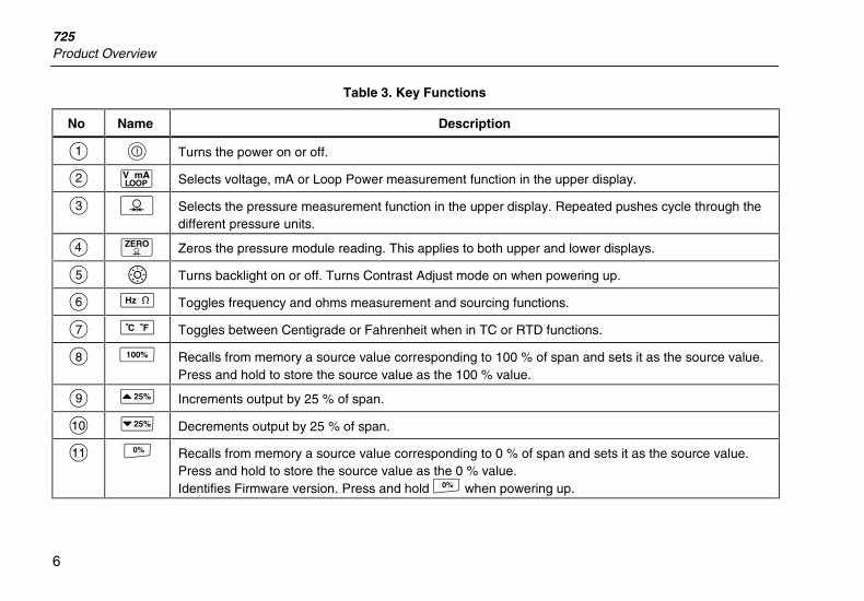
Table 3. Key Functions
No Name Description
Turns the power on or off.
Selects voltage, mA or Loop Power measurement function in the upper display.
Selects the pressure measurement function in the upper display. Repeated pushes cycle through thedifferent pressure units.
Zeros the pressure module reading. This applies to both upper and lower displays.
Turns backlight on or off. Turns Contrast Adjust mode on when powering up.
Toggles frequency and ohms measurement and sourcing functions.
Toggles between Centigrade or Fahrenheit when in TC or RTD functions.
Recalls from memory a source value corresponding to 100 % of span and sets it as the source value.Press and hold to store the source value as the 100 % value.
Increments output by 25 % of span.
Decrements output by 25 % of span.
Recalls from memory a source value corresponding to 0 % of span and sets it as the source value.Press and hold to store the source value as the 0 % value.Identifies Firmware version. Press and hold when powering up.
Multifunction Process CalibratorSafety Information
7
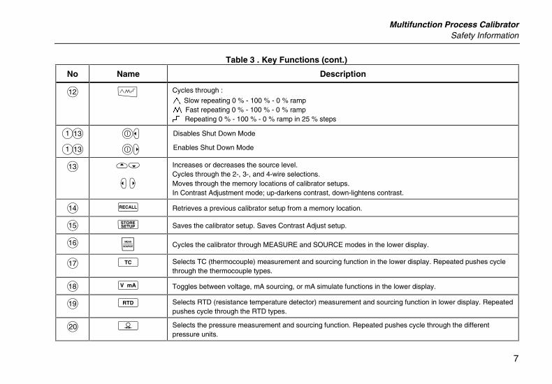
Table 3 . Key Functions (cont.)
No Name Description
Cycles through :
E Slow repeating 0 % - 100 % - 0 % rampP Fast repeating 0 % - 100 % - 0 % rampN Repeating 0 % - 100 % - 0 % ramp in 25 % steps
Disables Shut Down Mode
Enables Shut Down Mode
Increases or decreases the source level.Cycles through the 2-, 3-, and 4-wire selections.Moves through the memory locations of calibrator setups.In Contrast Adjustment mode; up-darkens contrast, down-lightens contrast.
Retrieves a previous calibrator setup from a memory location.
Saves the calibrator setup. Saves Contrast Adjust setup.
Cycles the calibrator through MEASURE and SOURCE modes in the lower display.
Selects TC (thermocouple) measurement and sourcing function in the lower display. Repeated pushes cyclethrough the thermocouple types.
Toggles between voltage, mA sourcing, or mA simulate functions in the lower display.
Selects RTD (resistance temperature detector) measurement and sourcing function in lower display. Repeatedpushes cycle through the RTD types.
Selects the pressure measurement and sourcing function. Repeated pushes cycle through the differentpressure units.

725Product Overview
8
Display
Low BatterySymbol
LoopAnnunciator
Memory Locationsfor Calibrator Setups
UnitsDisplay
AutoRamp
ModeIndicator
sh07f.eps
Figure 3. Elements of a Typical Display

Multifunction Process CalibratorReplacing the Batteries
9
Replacing the Batteries
WarningTo avoid false readings, which could lead topossible electric shock or personal injury,replace the batteries as soon as the batteryindicator () appears.
Battery andCompartment
FuseCompartment
sh38f.eps
Figure 4. Replacing the Batteries
725Product Overview
10
Replacing the FusesThe calibrator comes equipped with two 0.05A, 250V,socketed fuses to protect the calibrator.
WarningTo avoid electrical shock, remove the testleads from the calibrator before opening thebattery door. Close and latch the batterydoor before using the calibrator.
The fuses can be removed and checked for resistance. Avalue of < 10 Ω is good. Problems while measuring usingthe right jacks indicate that F3 may have opened. If youcan’t measure or source current with the left jacks, F4may have opened. To replace the fuses, refer to Figure 4and perform the following steps:
1. Turn the calibrator off, remove the test leads from theterminals, and hold the calibrator face down.
2. Using a flat-blade screwdriver, turn the battery doorscrews 1/4-turn counterclockwise and remove thebattery door.
3. Remove and replace the damaged fuse.
4. Replace the battery door and secure it by turning thescrews 1/4-turn clockwise.
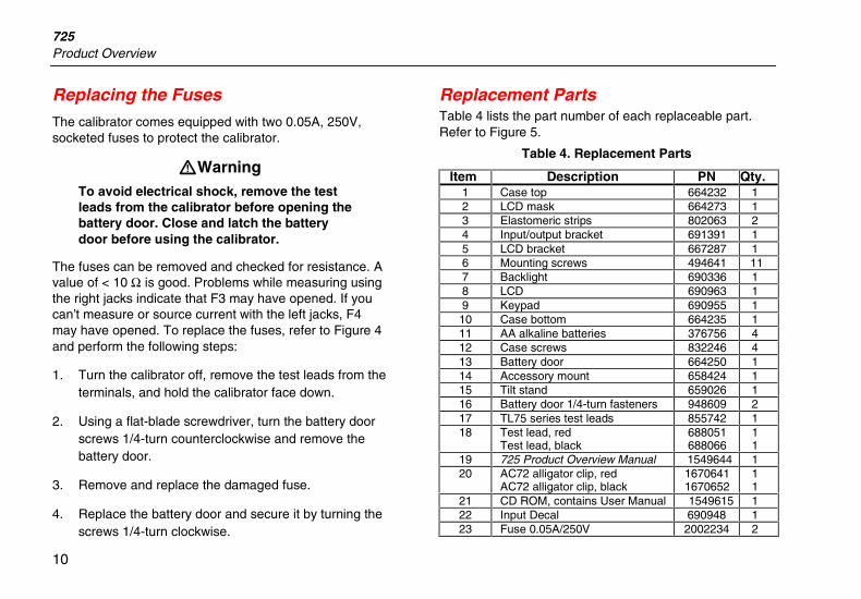
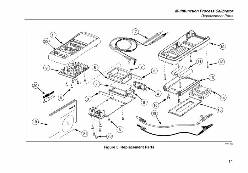
Replacement PartsTable 4 lists the part number of each replaceable part.Refer to Figure 5.
Table 4. Replacement Parts
Item Description PN Qty.1 Case top 664232 12 LCD mask 664273 13 Elastomeric strips 802063 24 Input/output bracket 691391 15 LCD bracket 667287 16 Mounting screws 494641 117 Backlight 690336 18 LCD 690963 19 Keypad 690955 110 Case bottom 664235 111 AA alkaline batteries 376756 412 Case screws 832246 413 Battery door 664250 114 Accessory mount 658424 115 Tilt stand 659026 116 Battery door 1/4-turn fasteners 948609 217 TL75 series test leads 855742 118 Test lead, red
Test lead, black688051688066
11
19 725 Product Overview Manual 1549644 120 AC72 alligator clip, red
AC72 alligator clip, black16706411670652
11
21 CD ROM, contains User Manual 1549615 122 Input Decal 690948 123 Fuse 0.05A/250V 2002234 2
Multifunction Process CalibratorReplacement Parts
11
1
8
6
6
9
19
10
12
13
2
18
20
17
3
4
53
7
16
11
14
15
2123
22
zi45f.eps
Figure 5. Replacement Parts
725Product Overview
12
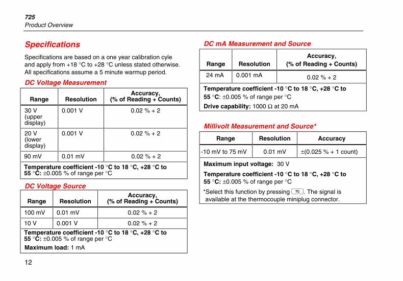
SpecificationsSpecifications are based on a one year calibration cyleand apply from +18 °C to +28 °C unless stated otherwise.All specifications assume a 5 minute warmup period.
DC Voltage Measurement
Range ResolutionAccuracy,
(% of Reading + Counts)
30 V(upperdisplay)
0.001 V 0.02 % + 2
20 V(lowerdisplay)
0.001 V 0.02 % + 2
90 mV 0.01 mV 0.02 % + 2
Temperature coefficient -10 °C to 18 °C, +28 °C to55 °C: ±0.005 % of range per °C
DC Voltage Source
Range ResolutionAccuracy,
(% of Reading + Counts)
100 mV 0.01 mV 0.02 % + 2
10 V 0.001 V 0.02 % + 2
Temperature coefficient -10 °C to 18 °C, +28 °C to55 °C: ±0.005 % of range per °CMaximum load: 1 mA
DC mA Measurement and Source
Range ResolutionAccuracy,
(% of Reading + Counts)
24 mA 0.001 mA 0.02 % + 2
Temperature coefficient -10 °C to 18 °C, +28 °C to55 °C: ±0.005 % of range per °CDrive capability: 1000 Ω at 20 mA
Millivolt Measurement and Source*
Range Resolution Accuracy
-10 mV to 75 mV 0.01 mV ±(0.025 % + 1 count)
Maximum input voltage: 30 V
Temperature coefficient -10 °C to 18 °C, +28 °C to55 °C: ±0.005 % of range per °C
*Select this function by pressing . The signal is available at the thermocouple miniplug connector.
Multifunction Process CalibratorSpecifications
13
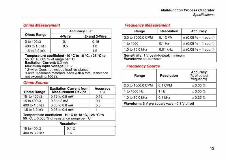
Ohms Measurement
Accuracy ± Ω*Ohms Range 4-Wire 2- and 3-Wire
0 to 400 Ω 0.1 0.15400 to 1.5 kΩ 0.5 1.01.5 to 3.2 kΩ 1 1.5Temperature coefficient -10 °C to 18 °C, +28 °C to55 °C: ±0.005 % of range per °CExcitation Current: 0.2 mAMaximum input voltage: 30 V* 2-wire: Does not include lead resistance.3-wire: Assumes matched leads with a total resistancenot exceeding 100 Ω.
Ohms Source
Ohms RangeExcitation Current from
Measurement DeviceAccuracy
± Ω15 to 400 Ω 0.15 to 0.5 mA 0.1515 to 400 Ω 0.5 to 2 mA 0.1400 to 1.5 kΩ 0.05 to 0.8 mA 0.51.5 to 3.2 kΩ 0.05 to 0.4 mA 1
Temperature coefficient -10 °C to 18 °C, +28 °C to55 °C: ± 0.005 % of resistance range per °C
Resolution15 to 400 Ω 0.1 Ω400 to 3.2 kΩ 1 Ω
Frequency Measurement
Range Resolution Accuracy
2.0 to 1000.0 CPM 0.1 CPM ± (0.05 % + 1 count)
1 to 1000 0.1 Hz ± (0.05 % + 1 count)
1.0 to 10.0 kHz 0.01 kHz ± (0.05 % + 1 count)
Sensitivity: 1 V peak-to-peak minimumWaveform: squarewave
Frequency Source
Range ResolutionAccuracy
(% of outputfrequency)
2.0 to 1000.0 CPM 0.1 CPM ± 0.05 %
1 to 1000 Hz 1 Hz ± 0.05 %
1.0 to 10.0 kHz 0.1 kHz ± 0.25 %
Waveform: 5 V p-p squarewave, -0.1 V offset

725 Product Overview
14
Temperature, Thermocouples
Type
Range Measure and Source Accuracies (ITS-90)
J -200 to 0 °C 0 to 1200 °C
1.0 °C 0.7 °C
K -200 to 0 °C 0 to 1370 °C
1.2 °C 0.8 °C
T -200 to 0 °C 0 to 400 °C
1.2 °C 0.8 °C
E -200 to 0 °C 0 to 950 °C
0.9 °C 0.7 °C
R -20 to 0 °C 0 to 500 °C 500 to 1750 °C
2.5 °C 1.8 °C 1.4 °C
S -20 to 0 °C 0 to 500 °C 500 to 1750 °C
2.5 °C 1.8 °C 1.5 °C
B 600 to 800 °C 800 to 1000 °C 1000 to 1800 °C
2.2 °C 1.8 °C 1.4 °C
L -200 to 0 °C 0 to 900 °C
0.85 °C 0.7 °C
U -200 to 0 °C 0 to 400 °C
1.1 °C 0.75 °C
N -200 to 0 °C 0 to 1300 °C
1.5 °C 0.9 °C
XK -200 to -100 °C -100 to 800 °C
0.5 °C 0.6 °C
BP 0 to 800 °C 800 to 2500 °C
1.2 °C 2.5 °C
Resolution: J, K, T, E, L, N, U, XK, BP: 0.1 °C, 0.1 °F B, R, S: 1 °C, 1 °F
Loop Power Supply Voltage: 24 V Maximum current: 22 mA
Short circuit protected
RTD Excitation (simulation)
Allowable Excitation by RTD type
Ni 120 0.15 to 3.0 mA
Pt 100-385 0.15 to 3.0 mA
Pt 100-392 0.15 to 3.0 mA
Pt 100-JIS 0.15 to 3.0 mA
Pt 200-385 0.05 to 0.80 mA
Pt 500-385 0.05 to 0.80 mA
Pt 1000-385 0.05 to 0.40 mA
Pressure Measurement
Range Resolution Accuracy Units
Determined by pressure module
5 digits Determined by pressure module
psi, inH2O@4 °C, inH2O@20 °C, kPa, cmH2O@4 °C, cmH2O@20 °C, bar, mbar, kg/cm2, mmHg, inHg

Multifunction Process Calibrator Specifications
15
Temperature, RTD Ranges, and Accuracies (ITS-90)
Accuracy Type Range °C Measure
4-Wire °C Measure
2- and 3-Wire*
°C
Source °C
Ni120 -80 to 260 0.2 0.3 0.2
Pt100-385 - 200 to 800 0.33 0.5 0.33
Pt100-392 -200 to 630 0.3 0.5 0.3
Pt100-JIS -200 to 630 0.3 0.5 0.3
Pt200-385 -200 to 250 250 to 630
0.2 0.8
0.3 1.6
0.2 0.8
Pt500-385 -200 to 500 500 to 630
0.3 0.4
0.6 0.9
0.3 0.4
Pt1000-385 -200 to 100 100 to 630
0.2 0.2
0.4 0.5
0.2 0.2
Resolution: 0.1 °C, 0.1 °F Allowable excitation current (source): Ni120, Pt100-385, Pt100-392, Pt100-JIS: 0.15 to 3.0 mA Pt200-385, Pt500-385: 0.05 to 0.80 mA; Pt1000-385: 0.05 to 0.40 mA RTD Source: Addresses pulsed transmitters and PLCs with pulses as short as 5 ms. * 2-wire: Does not include lead resistance. 3-wire: Assumes matched leads with a total resistance not exceeding 100 Ω.
General Specifications
Operating temperature
-10 °C to 55 °C
Storage temperature - 20 °C to 71 °C
Operating altitude 3000 meters above mean sea level
Relative Humidity (% RH operating without condensation)
90 % (10 to 30 °C) 75 % (30 to 40 °C) 45 % (40 to 50 °C) 35 % (50 to 55 °C) uncontrolled < 10 °C
Vibration Random, 2 g, 5 to 500 Hz
Safety EN 61010-1:1993, ANSI/ISA S82.01-1994; CAN/CSA C22.2 No 1010.1:1992
Power requirements 4 AA alkaline batteries
Size 96 x 200 x 47 mm. (3.75 x 7.9 x 1.86 in)
Weight 650 gm (1 lb, 7 oz)
Protection Class Pollution Degree II

725Product Overview
16


