

OPERATIONS MANUALba76143e04 09/2015
4010-3
MultiLab 4010-3
DIGITAL METER FOR IDS SENSORS

MultiLab 4010-3
For the most recent version of the manual, please visit www.ysi.com.
Contact YSI1725 Brannum LaneYellow Springs, OH 45387 USATel: +1 937-767-7241
800-765-4974Email: [email protected]: www.ysi.com
Copyright © 2015 Xylem Inc.
2 ba76143e04 09/2015

MultiLab 4010-3 - Contents
MultiLab 4010-3 Contents
1 Overview . . . . . . . . . . . . . . . . . . . . . . . . . . . . . . . . . . . . . . . . . . 71.1 Meter MultiLab 4010-3 . . . . . . . . . . . . . . . . . . . . . . . . . . . . . . . . 71.2 Sensors. . . . . . . . . . . . . . . . . . . . . . . . . . . . . . . . . . . . . . . . . . . . 8
1.2.1 IDS sensors . . . . . . . . . . . . . . . . . . . . . . . . . . . . . . . . . . . . 81.2.2 IDS adapter for analog sensors . . . . . . . . . . . . . . . . . . . . . 91.2.3 Automatic sensor recognition . . . . . . . . . . . . . . . . . . . . . . 9
2 Safety . . . . . . . . . . . . . . . . . . . . . . . . . . . . . . . . . . . . . . . . . . . 102.1 Safety information . . . . . . . . . . . . . . . . . . . . . . . . . . . . . . . . . . . 10
2.1.1 Safety information in the operating manual . . . . . . . . . . . 102.1.2 Safety signs on the meter . . . . . . . . . . . . . . . . . . . . . . . . 102.1.3 Further documents providing safety information . . . . . . . 10
2.2 Safe operation. . . . . . . . . . . . . . . . . . . . . . . . . . . . . . . . . . . . . . 102.2.1 Authorized use. . . . . . . . . . . . . . . . . . . . . . . . . . . . . . . . . 102.2.2 Requirements for safe operation . . . . . . . . . . . . . . . . . . . 112.2.3 Unauthorized use. . . . . . . . . . . . . . . . . . . . . . . . . . . . . . . 11
3 Commissioning . . . . . . . . . . . . . . . . . . . . . . . . . . . . . . . . . . . 123.1 Scope of delivery . . . . . . . . . . . . . . . . . . . . . . . . . . . . . . . . . . . 123.2 Power supply . . . . . . . . . . . . . . . . . . . . . . . . . . . . . . . . . . . . . . 123.3 Initial commissioning. . . . . . . . . . . . . . . . . . . . . . . . . . . . . . . . . 12
3.3.1 Connecting the power pack . . . . . . . . . . . . . . . . . . . . . . . 13
4 Operation . . . . . . . . . . . . . . . . . . . . . . . . . . . . . . . . . . . . . . . . 144.1 General operating principles . . . . . . . . . . . . . . . . . . . . . . . . . . . 14
4.1.1 Keypad. . . . . . . . . . . . . . . . . . . . . . . . . . . . . . . . . . . . . . . 144.1.2 Display . . . . . . . . . . . . . . . . . . . . . . . . . . . . . . . . . . . . . . . 154.1.3 Status information . . . . . . . . . . . . . . . . . . . . . . . . . . . . . . 154.1.4 Instrument connectors . . . . . . . . . . . . . . . . . . . . . . . . . . . 164.1.5 Channel display . . . . . . . . . . . . . . . . . . . . . . . . . . . . . . . . 174.1.6 Sensor info. . . . . . . . . . . . . . . . . . . . . . . . . . . . . . . . . . . . 174.1.7 Display of several sensors in the measuring mode . . 18
4.2 Switching on the meter . . . . . . . . . . . . . . . . . . . . . . . . . . . . . . . 194.3 Switching off the meter . . . . . . . . . . . . . . . . . . . . . . . . . . . . . . . 194.4 Login with user name . . . . . . . . . . . . . . . . . . . . . . . . . . . . . . . . 194.5 Navigation . . . . . . . . . . . . . . . . . . . . . . . . . . . . . . . . . . . . . . . . . 21
4.5.1 Operating modes . . . . . . . . . . . . . . . . . . . . . . . . . . . . . . . 214.5.2 Measured value display . . . . . . . . . . . . . . . . . . . . . . . . . . 214.5.3 Menus and dialogs. . . . . . . . . . . . . . . . . . . . . . . . . . . . . . 214.5.4 Example 1 on navigation: Setting the language . . . . . . . 234.5.5 Example 2 on navigation: Setting the date and time . . . . 25
ba76143e04 09/2015 3
Contents MultiLab 4010-3
5 pH value. . . . . . . . . . . . . . . . . . . . . . . . . . . . . . . . . . . . . . . . . . 275.1 Measuring . . . . . . . . . . . . . . . . . . . . . . . . . . . . . . . . . . . . . . . . 27
5.1.1 Measuring the pH value . . . . . . . . . . . . . . . . . . . . . . . . . 275.1.2 Measuring the temperature . . . . . . . . . . . . . . . . . . . . . . 28
5.2 pH calibration. . . . . . . . . . . . . . . . . . . . . . . . . . . . . . . . . . . . . . 295.2.1 Why calibrate? . . . . . . . . . . . . . . . . . . . . . . . . . . . . . . . . 295.2.2 When do you have to calibrate? . . . . . . . . . . . . . . . . . . . 295.2.3 Carrying out automatic calibration (AutoCal) . . . . 295.2.4 Carrying out a manual calibration (ConCal) . . . . . . . . . . 325.2.5 Calibration points . . . . . . . . . . . . . . . . . . . . . . . . . . . . . . 355.2.6 Calibration data . . . . . . . . . . . . . . . . . . . . . . . . . . . . . . . 365.2.7 Continuous measurement control (CMC function) . . 385.2.8 QSC function (sensor quality control) . . . . . . . . . . . . 40
6 ORP voltage . . . . . . . . . . . . . . . . . . . . . . . . . . . . . . . . . . . . . . 436.1 Measuring . . . . . . . . . . . . . . . . . . . . . . . . . . . . . . . . . . . . . . . . 43
6.1.1 Measuring the ORP . . . . . . . . . . . . . . . . . . . . . . . . . . . . 436.1.2 Measuring the relative ORP . . . . . . . . . . . . . . . . . . . . . . 446.1.3 Measuring the temperature . . . . . . . . . . . . . . . . . . . . . . 46
6.2 ORP calibration . . . . . . . . . . . . . . . . . . . . . . . . . . . . . . . . . . . . 46
7 Ion concentration . . . . . . . . . . . . . . . . . . . . . . . . . . . . . . . . . . 477.1 Measuring . . . . . . . . . . . . . . . . . . . . . . . . . . . . . . . . . . . . . . . . 47
7.1.1 Measuring the ion concentration . . . . . . . . . . . . . . . . . . 477.1.2 Measuring the temperature . . . . . . . . . . . . . . . . . . . . . . 49
7.2 Calibration . . . . . . . . . . . . . . . . . . . . . . . . . . . . . . . . . . . . . . . . 507.2.1 Why calibrate? . . . . . . . . . . . . . . . . . . . . . . . . . . . . . . . . 507.2.2 When to calibrate? . . . . . . . . . . . . . . . . . . . . . . . . . . . . . 507.2.3 Calibration (ISE Cal). . . . . . . . . . . . . . . . . . . . . . . . . . . . 507.2.4 Calibration standards . . . . . . . . . . . . . . . . . . . . . . . . . . . 537.2.5 Calibration data . . . . . . . . . . . . . . . . . . . . . . . . . . . . . . . 53
7.3 Selecting the measuring method . . . . . . . . . . . . . . . . . . . . . . . 567.3.1 Standard addition . . . . . . . . . . . . . . . . . . . . . . . . . . . . . . 577.3.2 Standard subtraction . . . . . . . . . . . . . . . . . . . . . . . . . . . 597.3.3 Sample addition . . . . . . . . . . . . . . . . . . . . . . . . . . . . . . . 627.3.4 Sample subtraction . . . . . . . . . . . . . . . . . . . . . . . . . . . . . 647.3.5 Standard addition with blank value correction (Blank value
addition) . . . . . . . . . . . . . . . . . . . . . . . . . . . . . . . . . 66
8 Dissolved oxygen (D.O.) . . . . . . . . . . . . . . . . . . . . . . . . . . . . 698.1 Measuring . . . . . . . . . . . . . . . . . . . . . . . . . . . . . . . . . . . . . . . . 69
8.1.1 Measuring D.O. . . . . . . . . . . . . . . . . . . . . . . . . . . . . . . . 698.1.2 Measuring the temperature . . . . . . . . . . . . . . . . . . . . . . 71
8.2 Calibration . . . . . . . . . . . . . . . . . . . . . . . . . . . . . . . . . . . . . . . . 718.2.1 Why calibrate? . . . . . . . . . . . . . . . . . . . . . . . . . . . . . . . . 718.2.2 When to calibrate? . . . . . . . . . . . . . . . . . . . . . . . . . . . . . 718.2.3 Calibration procedures . . . . . . . . . . . . . . . . . . . . . . . . . . 718.2.4 1-point calibration . . . . . . . . . . . . . . . . . . . . . . . . . . . . . . 728.2.5 2-point calibration . . . . . . . . . . . . . . . . . . . . . . . . . . . . . . 738.2.6 Calibration data . . . . . . . . . . . . . . . . . . . . . . . . . . . . . . . 74
4 ba76143e04 09/2015

MultiLab 4010-3 Contents
9 Conductivity . . . . . . . . . . . . . . . . . . . . . . . . . . . . . . . . . . . . . . 779.1 Measuring . . . . . . . . . . . . . . . . . . . . . . . . . . . . . . . . . . . . . . . . 77
9.1.1 Measuring the conductivity . . . . . . . . . . . . . . . . . . . . . . . 779.1.2 Measuring the temperature . . . . . . . . . . . . . . . . . . . . . . 79
9.2 Temperature compensation. . . . . . . . . . . . . . . . . . . . . . . . . . . 799.3 Calibration . . . . . . . . . . . . . . . . . . . . . . . . . . . . . . . . . . . . . . . . 80
9.3.1 Why calibrate? . . . . . . . . . . . . . . . . . . . . . . . . . . . . . . . . 809.3.2 When to calibrate? . . . . . . . . . . . . . . . . . . . . . . . . . . . . . 809.3.3 Determining the cell constant (calibration in control
standard) . . . . . . . . . . . . . . . . . . . . . . . . . . . . . . . . 809.3.4 Calibration data . . . . . . . . . . . . . . . . . . . . . . . . . . . . . . . 81
10 Settings . . . . . . . . . . . . . . . . . . . . . . . . . . . . . . . . . . . . . . . . . . 8310.1 pH measurement settings . . . . . . . . . . . . . . . . . . . . . . . . . . . . 83
10.1.1 Settings for pH measurements . . . . . . . . . . . . . . . . . . . . 8310.1.2 Buffer sets for calibration . . . . . . . . . . . . . . . . . . . . . . . . 8510.1.3 Calibration interval . . . . . . . . . . . . . . . . . . . . . . . . . . . . . 87
10.2 ORP measurement settings. . . . . . . . . . . . . . . . . . . . . . . . . . . 8810.3 ISE measurement settings. . . . . . . . . . . . . . . . . . . . . . . . . . . . 8810.4 D.O. measurement settings . . . . . . . . . . . . . . . . . . . . . . . . . . . 91
10.4.1 Settings for D.O. measurement . . . . . . . . . . . . . . . . . . . 9110.4.2 Enter Sensor Cap coefficients . . . . . . . . . . . . . . . . . . . . 9110.4.3 Saturation local . . . . . . . . . . . . . . . . . . . . . . . . . . . . . . . . 91
10.5 Cond measurement settings . . . . . . . . . . . . . . . . . . . . . . . . . . 9110.5.1 Settings for IDS conductivity sensors . . . . . . . . . . . . . . . 91
10.6 Sensor-independent settings . . . . . . . . . . . . . . . . . . . . . . . . . . 9510.6.1 System . . . . . . . . . . . . . . . . . . . . . . . . . . . . . . . . . . . . . . 9510.6.2 Data storage . . . . . . . . . . . . . . . . . . . . . . . . . . . . . . . . . . 9610.6.3 Automatic Stability control . . . . . . . . . . . . . . . . . . . . . . . 96
10.7 Reset . . . . . . . . . . . . . . . . . . . . . . . . . . . . . . . . . . . . . . . . . . . . 9710.7.1 Resetting the measurement settings . . . . . . . . . . . . . . . 9710.7.2 Resetting the system settings. . . . . . . . . . . . . . . . . . . . 100
11 Data storage . . . . . . . . . . . . . . . . . . . . . . . . . . . . . . . . . . . . . 10111.1 Manual data storage . . . . . . . . . . . . . . . . . . . . . . . . . . . . . . . 10111.2 Automatic data storage at intervals . . . . . . . . . . . . . . . . . 10111.3 Measurement data storage . . . . . . . . . . . . . . . . . . . . . . . . . . 104
11.3.1 Editing the measurement data storage. . . . . . . . . . . . . 10411.3.2 Erasing the measurement data storage . . . . . . . . . . . . 10511.3.3 Measurement dataset. . . . . . . . . . . . . . . . . . . . . . . . . . 10511.3.4 Storage locations . . . . . . . . . . . . . . . . . . . . . . . . . . . . . 106
12 Transmitting data . . . . . . . . . . . . . . . . . . . . . . . . . . . . . . . . . 10712.1 Outputting current measurement data . . . . . . . . . . . . . . . . . . 10712.2 Transmitting data . . . . . . . . . . . . . . . . . . . . . . . . . . . . . . . . . . 10712.3 Connecting the PC / USB-B interface (USB Device) . . . . 10712.4 Connecting a USB memory device/USB printer
(USB-A interface (USB Host)) . . . . . . . . . . . . . . . . . . . . . . . . 10812.5 Options for data transmission to the USB-B (PC)
interface and the USB-A (USB printer) interface . . . . . . . . . . 10912.6 Data transmission to the USB-A interface
ba76143e04 09/2015 5

Contents MultiLab 4010-3
(USB memory device) . . . . . . . . . . . . . . . . . . . . . . . . . . . . . . 11012.7 MultiLab Importer. . . . . . . . . . . . . . . . . . . . . . . . . . . . . . . . . . 11012.8 BOD Analyst Pro . . . . . . . . . . . . . . . . . . . . . . . . . . . . . . . . . . 110
13 Maintenance, cleaning, disposal. . . . . . . . . . . . . . . . . . . . . 11113.1 Maintenance . . . . . . . . . . . . . . . . . . . . . . . . . . . . . . . . . . . . . 111
13.1.1 General maintenance activities . . . . . . . . . . . . . . . . . . 11113.1.2 Exchanging the battery. . . . . . . . . . . . . . . . . . . . . . . . . 111
13.2 Cleaning. . . . . . . . . . . . . . . . . . . . . . . . . . . . . . . . . . . . . . . . . 11213.3 Packing . . . . . . . . . . . . . . . . . . . . . . . . . . . . . . . . . . . . . . . . . 11213.4 Disposal . . . . . . . . . . . . . . . . . . . . . . . . . . . . . . . . . . . . . . . . . 112
14 What to do if... . . . . . . . . . . . . . . . . . . . . . . . . . . . . . . . . . . . . 11414.1 pH . . . . . . . . . . . . . . . . . . . . . . . . . . . . . . . . . . . . . . . . . . . . . 11414.2 ISE . . . . . . . . . . . . . . . . . . . . . . . . . . . . . . . . . . . . . . . . . . . . . 11614.3 Dissolved oxygen. . . . . . . . . . . . . . . . . . . . . . . . . . . . . . . . . . 11714.4 Conductivity . . . . . . . . . . . . . . . . . . . . . . . . . . . . . . . . . . . . . . 11814.5 General information . . . . . . . . . . . . . . . . . . . . . . . . . . . . . . . . 118
15 Technical data. . . . . . . . . . . . . . . . . . . . . . . . . . . . . . . . . . . . 12015.1 Measuring ranges, resolution, accuracy . . . . . . . . . . . . . . . . 12015.2 General data . . . . . . . . . . . . . . . . . . . . . . . . . . . . . . . . . . . . . 120
16 Firmware update . . . . . . . . . . . . . . . . . . . . . . . . . . . . . . . . . . 12416.1 Firmware update for the meter MultiLab 4010-3 . . . . . . . . . . 12416.2 Firmware-Update for IDS Sensors. . . . . . . . . . . . . . . . . . . . . 125
17 Glossary . . . . . . . . . . . . . . . . . . . . . . . . . . . . . . . . . . . . . . . . 126
18 Index . . . . . . . . . . . . . . . . . . . . . . . . . . . . . . . . . . . . . . . . . . . 129
19 Appendix . . . . . . . . . . . . . . . . . . . . . . . . . . . . . . . . . . . . . . . . 13219.1 Oxygen solubility table. . . . . . . . . . . . . . . . . . . . . . . . . . . . . . 13219.2 DO% Calibration values. . . . . . . . . . . . . . . . . . . . . . . . . . . . . 134
20 Contact Information . . . . . . . . . . . . . . . . . . . . . . . . . . . . . . . 13520.1 Ordering & Technical Support . . . . . . . . . . . . . . . . . . . . . . . . 13520.2 Service Information . . . . . . . . . . . . . . . . . . . . . . . . . . . . . . . . 135
6 ba76143e04 09/2015
MultiLab 4010-3 Overview
1 Overview
1.1 Meter MultiLab 4010-3
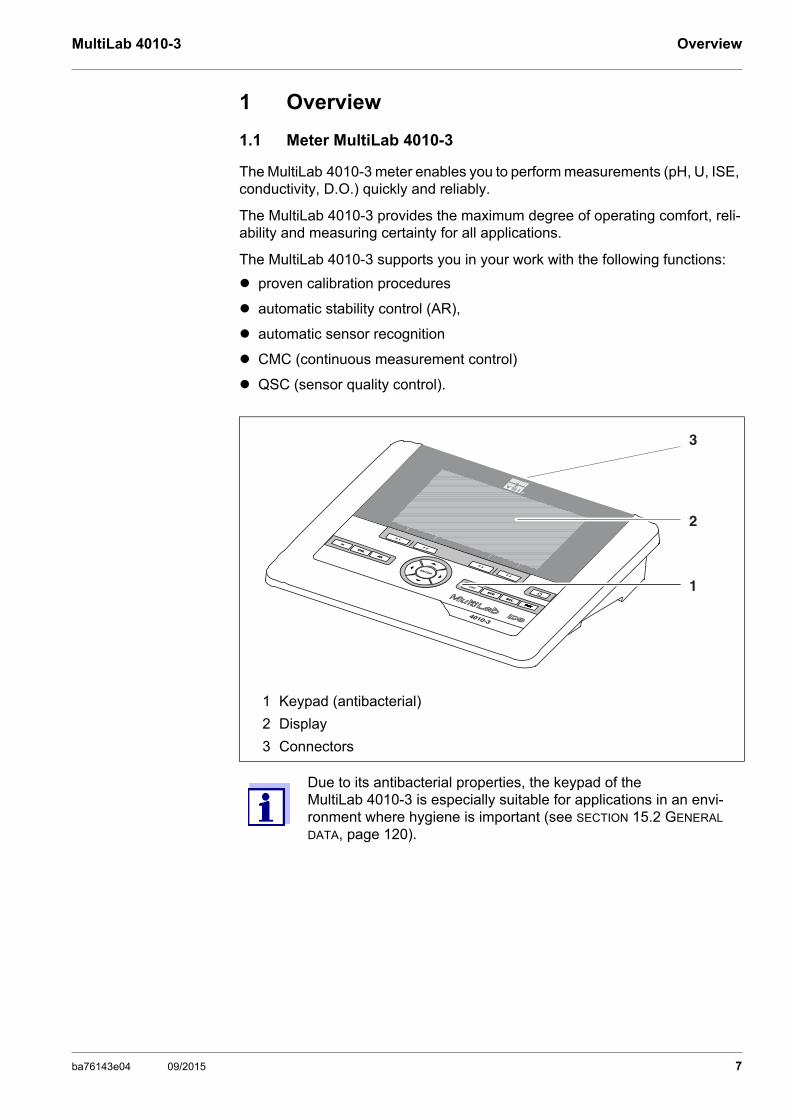
The MultiLab 4010-3 meter enables you to perform measurements (pH, U, ISE, conductivity, D.O.) quickly and reliably.
The MultiLab 4010-3 provides the maximum degree of operating comfort, reli-ability and measuring certainty for all applications.
The MultiLab 4010-3 supports you in your work with the following functions:
proven calibration procedures
automatic stability control (AR),
automatic sensor recognition
CMC (continuous measurement control)
QSC (sensor quality control).
1 Keypad (antibacterial)
2 Display
3 Connectors
Due to its antibacterial properties, the keypad of the MultiLab 4010-3 is especially suitable for applications in an envi-ronment where hygiene is important (see SECTION 15.2 GENERAL DATA, page 120).
1
2
3
4010-3
ba76143e04 09/2015 7
Overview MultiLab 4010-3
1.2 Sensors
1.2.1 IDS sensors
IDS sensors
support the automatic sensor recognition
show only the settings relevant to the specific sensor in the setting menu
process signals in the sensor digitally so that precise and interference-free measurements are enabled even with long cables
facilitate to assign a sensor to a measured parameter with differently colored couplings
have quick-lock couplings with which to fix the sensors to the meter.
Sensor data fromIDS sensors
IDS sensors transmit the following sensor data to the meter:
SENSOR ID
– Sensor name
– Sensor series number
Calibration data
Measurement settings
The calibration data are updated in the IDS sensor after each calibration proce-dure. A message is displayed while the data are being updated in the sensor.
In the measured value display, you can display the sensor name and series number of the selected sensor with the [Info] softkey. You can then display further sensor data stored in the sensor with the [More] softkey (see section 4.1.6 SENSOR INFO, page 17).
8 ba76143e04 09/2015
MultiLab 4010-3 Overview
1.2.2 IDS adapter for analog sensors
With the aid of an IDS adapter, you can also operate analog sensorson the MultiLab 4010-3. The combination of the IDS adapter and analog sensor behaves like an IDS sensor.
The MultiLab 4010-3 has a recess where the IDS adapter (ADA 94/IDS DIN or ADA 94/IDS BNC), which is available as an accessory, can be permanently mounted.
The IDS adapter replaces a digital input (channel 2) with a connector for an analog pH/ U/ISE sensor (DIN or BNC plug) and a temperature sensor.
1.2.3 Automatic sensor recognition
The automatic sensor recognition for IDS sensors allows
to operate an IDS sensor with different meters without recalibrating
to operate different IDS sensors at one meter without recalibration
to assign measurement data to an IDS sensor
– Measurement datasets are always stored and output with the sensor name and sensor series number.
to assign calibration data to an IDS sensor
– Calibration data and calibration history are always stored and output with the sensor name and sensor series number.
to activate the correct cell constant for conductivity sensors automatically
to hide menus automatically that do not concern this sensor
To be able to use the automatic sensor recognition, a meter that supports the automatic sensor recognition (e.g. MultiLab 4010-3) and a digital IDS sensor are required. In digital IDS sensors, sensor data are stored that clearly identify the sensor. The sensor data are automatically taken over by the meter.
ba76143e04 09/2015 9
Safety MultiLab 4010-3
2 Safety
2.1 Safety information
2.1.1 Safety information in the operating manual
This operating manual provides important information on the safe operation of the meter. Read this operating manual thoroughly and make yourself familiar with the meter before putting it into operation or working with it. The operating manual must be kept in the vicinity of the meter so you can always find the infor-mation you need.
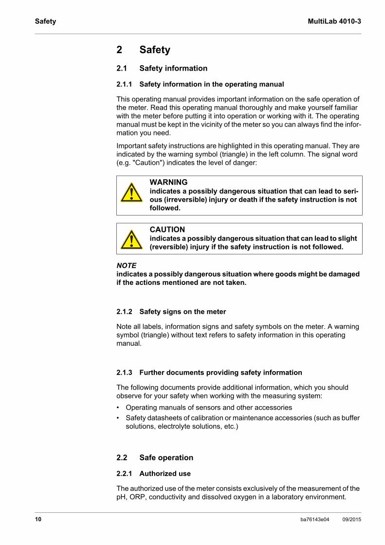
Important safety instructions are highlighted in this operating manual. They are indicated by the warning symbol (triangle) in the left column. The signal word (e.g. "Caution") indicates the level of danger:
NOTEindicates a possibly dangerous situation where goods might be damaged if the actions mentioned are not taken.
2.1.2 Safety signs on the meter
Note all labels, information signs and safety symbols on the meter. A warning symbol (triangle) without text refers to safety information in this operating manual.
2.1.3 Further documents providing safety information
The following documents provide additional information, which you should observe for your safety when working with the measuring system:
• Operating manuals of sensors and other accessories
• Safety datasheets of calibration or maintenance accessories (such as buffer solutions, electrolyte solutions, etc.)
2.2 Safe operation
2.2.1 Authorized use
The authorized use of the meter consists exclusively of the measurement of the pH, ORP, conductivity and dissolved oxygen in a laboratory environment.
WARNINGindicates a possibly dangerous situation that can lead to seri-ous (irreversible) injury or death if the safety instruction is not followed.
CAUTIONindicates a possibly dangerous situation that can lead to slight (reversible) injury if the safety instruction is not followed.
10 ba76143e04 09/2015

MultiLab 4010-3 Safety
Only the operation and running of the meter according to the instructions and technical specifications given in this operating manual is authorized (see section 15 TECHNICAL DATA, page 120).
Any other use is considered unauthorized.
2.2.2 Requirements for safe operation
Note the following points for safe operation:
• The meter may only be operated according to the authorized use specified above.
• The meter may only be supplied with power by the energy sources mentioned in this operating manual.
• The meter may only be operated under the environmental conditions mentioned in this operating manual.
• The meter may not be opened.
2.2.3 Unauthorized use
The meter must not be put into operation if:
• it is visibly damaged (e.g. after being transported)
• it was stored under adverse conditions for a lengthy period of time (storing conditions, see section 15 TECHNICAL DATA, page 120).
ba76143e04 09/2015 11
Commissioning MultiLab 4010-3
3 Commissioning
3.1 Scope of delivery
MeterMultiLab 4010-3
USB cable (A plug on mini B plug)
Power pack
Stand with stand base
Short instructions
Detailed operating manual
CD-ROM
3.2 Power supply
The MultiLab 4010-3 is supplied with power in the following ways:
Mains operation with the supplied power pack
Operation of the system clock with a buffer battery if there is no mains power supply (see section 13.1.2 EXCHANGING THE BATTERY, page 111).
3.3 Initial commissioning
Perform the following activities:
Connect the power pack (see section 3.3.1 CONNECTING THE POWER PACK, page 13)
Switch on the meter (see section 4.2 SWITCHING ON THE METER, page 19)
Set the date and time (see section 4.5.5 EXAMPLE 2 ON NAVIGATION: SETTING THE DATE AND TIME, page 25)
Mount the stand(see operating manual of the stand)
12 ba76143e04 09/2015
MultiLab 4010-3 Commissioning
3.3.1 Connecting the power pack
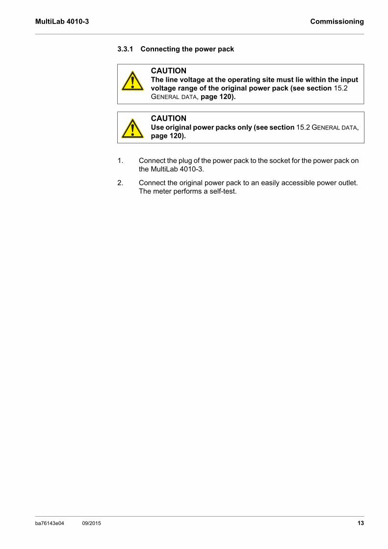
CAUTIONThe line voltage at the operating site must lie within the input voltage range of the original power pack (see section 15.2 GENERAL DATA, page 120).
CAUTIONUse original power packs only (see section 15.2 GENERAL DATA, page 120).
1. Connect the plug of the power pack to the socket for the power pack on the MultiLab 4010-3.
2. Connect the original power pack to an easily accessible power outlet.The meter performs a self-test.
ba76143e04 09/2015 13
Operation MultiLab 4010-3
4 Operation
4.1 General operating principles
4.1.1 Keypad
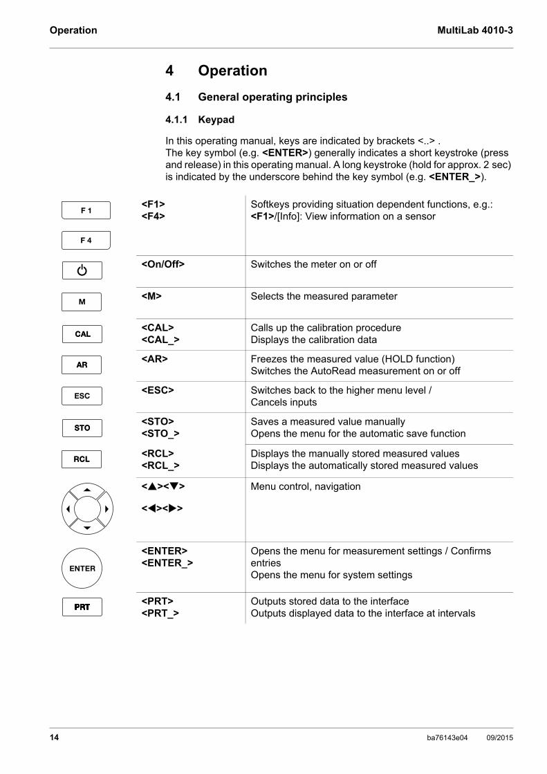
In this operating manual, keys are indicated by brackets <..> . The key symbol (e.g. <ENTER>) generally indicates a short keystroke (press and release) in this operating manual. A long keystroke (hold for approx. 2 sec) is indicated by the underscore behind the key symbol (e.g. <ENTER_>).
<F1><F4>
Softkeys providing situation dependent functions, e.g.: <F1>/[Info]: View information on a sensor
<On/Off> Switches the meter on or off
<M> Selects the measured parameter
<CAL><CAL_>
Calls up the calibration procedure Displays the calibration data
<AR> Freezes the measured value (HOLD function)Switches the AutoRead measurement on or off
<ESC> Switches back to the higher menu level /Cancels inputs
<STO><STO_>
Saves a measured value manuallyOpens the menu for the automatic save function
<RCL><RCL_>
Displays the manually stored measured valuesDisplays the automatically stored measured values
<><>
<><>
Menu control, navigation
<ENTER><ENTER_>
Opens the menu for measurement settings / Confirms entriesOpens the menu for system settings
<PRT><PRT_>
Outputs stored data to the interface Outputs displayed data to the interface at intervals
14 ba76143e04 09/2015
MultiLab 4010-3 Operation
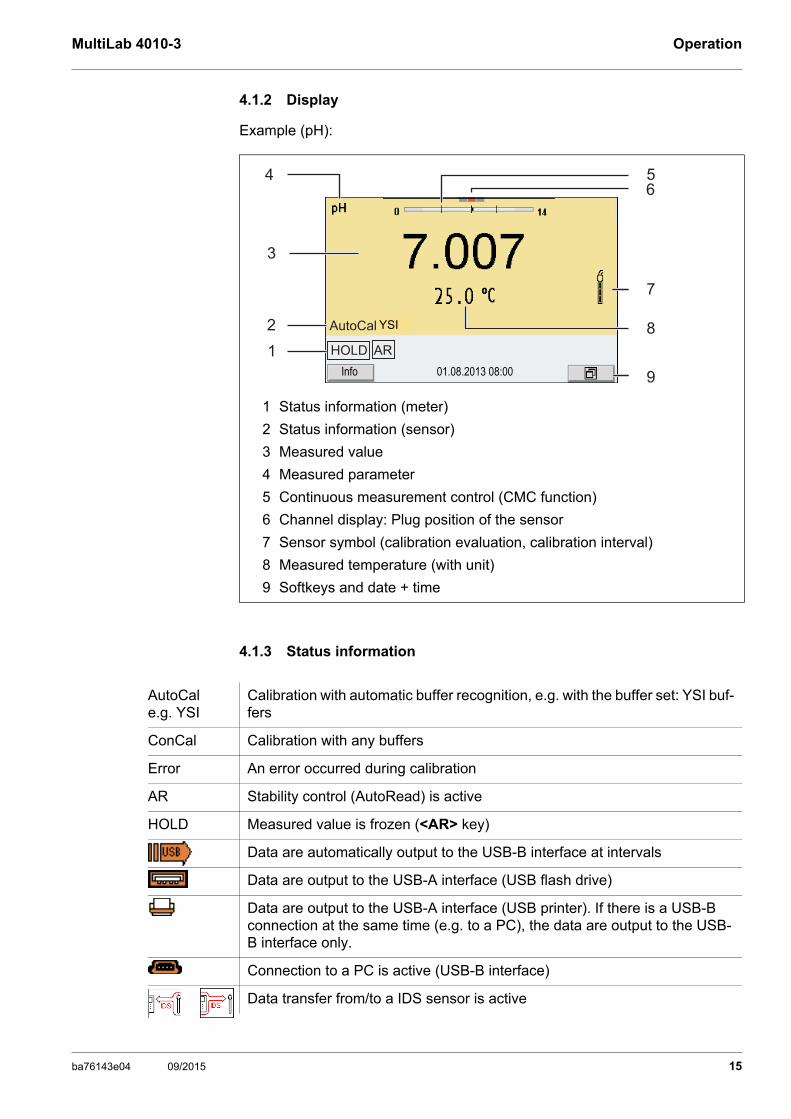
4.1.2 Display
Example (pH):
4.1.3 Status information
1 Status information (meter)
2 Status information (sensor)
3 Measured value
4 Measured parameter
5 Continuous measurement control (CMC function)
6 Channel display: Plug position of the sensor
7 Sensor symbol (calibration evaluation, calibration interval)
8 Measured temperature (with unit)
9 Softkeys and date + time
4
3
2
5
7
8
9
6
1 HOLD AR
AutoCal TEC
01.08.2013 08:00Info
YSI
AutoCal e.g. YSI
Calibration with automatic buffer recognition, e.g. with the buffer set: YSI buf-fers
ConCal Calibration with any buffers
Error An error occurred during calibration
AR Stability control (AutoRead) is active
HOLD Measured value is frozen (<AR> key)
Data are automatically output to the USB-B interface at intervals
Data are output to the USB-A interface (USB flash drive)
Data are output to the USB-A interface (USB printer). If there is a USB-B connection at the same time (e.g. to a PC), the data are output to the USB-B interface only.
Connection to a PC is active (USB-B interface)
Data transfer from/to a IDS sensor is active
ba76143e04 09/2015 15
Operation MultiLab 4010-3
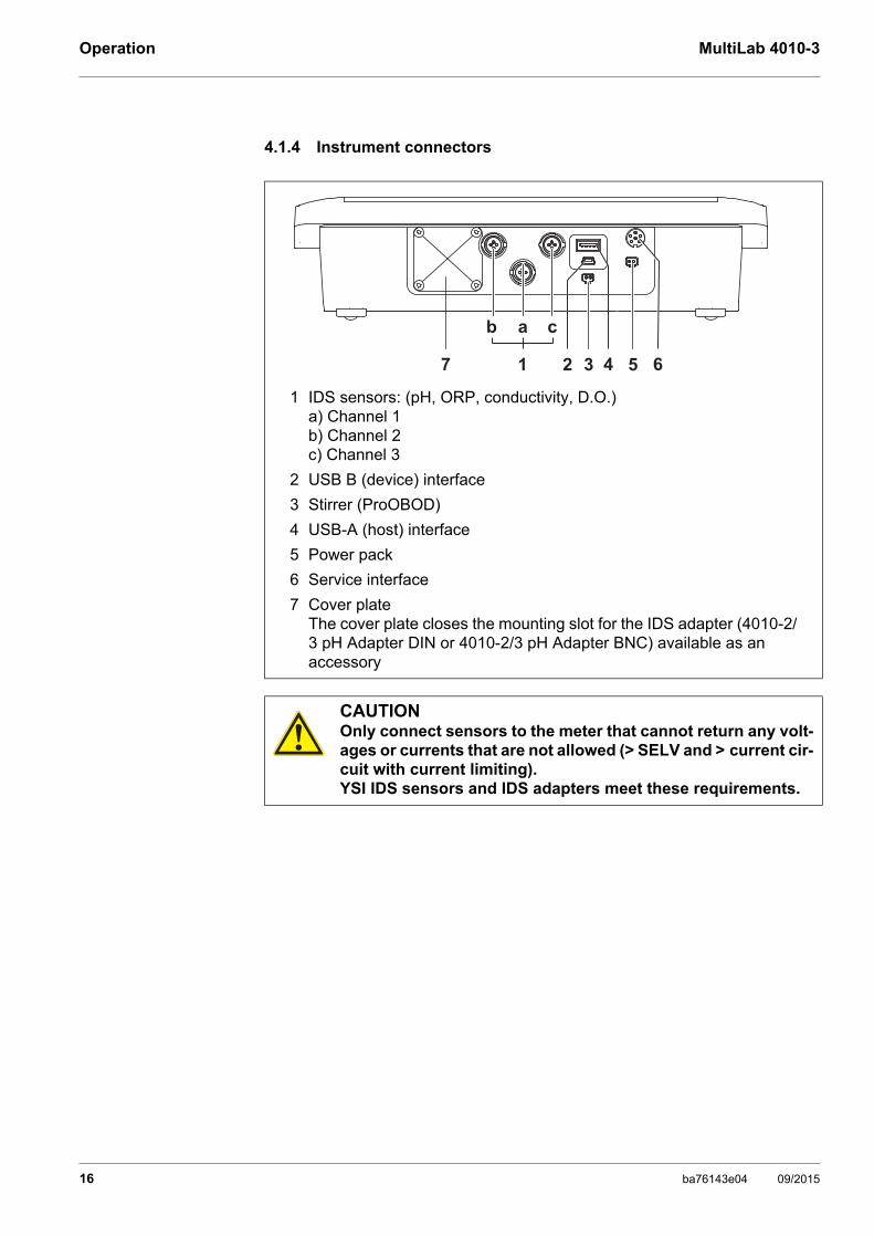
4.1.4 Instrument connectors
1 IDS sensors: (pH, ORP, conductivity, D.O.)a) Channel 1b) Channel 2c) Channel 3
2 USB B (device) interface
3 Stirrer (ProOBOD)
4 USB-A (host) interface
5 Power pack
6 Service interface
7 Cover plateThe cover plate closes the mounting slot for the IDS adapter (4010-2/3 pH Adapter DIN or 4010-2/3 pH Adapter BNC) available as an accessory
CAUTIONOnly connect sensors to the meter that cannot return any volt-ages or currents that are not allowed (> SELV and > current cir-cuit with current limiting). YSI IDS sensors and IDS adapters meet these requirements.
7 4 63 51
b a c
2
16 ba76143e04 09/2015

MultiLab 4010-3 Operation
4.1.5 Channel display
The MultiLab 4010-3 manages the connected sensors and displays which sen-sor is plugged to which connection.
4.1.6 Sensor info
You can display the current sensor data and sensor settings of a connected sensor at any time. The sensor data are available in the measured value dis-play with the /[Info] softkey.
1 Channel display: Display of the plug position for the respective parameterThe red bar indicates for each connected sensor to which plug posi-tion (channel) of the meter it is connected.
1. In the measured value display:Display the sensor data (sensor name, series number) with [Info].
1
01.08.2013 08:00Info
01.08.2013 08:00Info
ba76143e04 09/2015 17
Operation MultiLab 4010-3
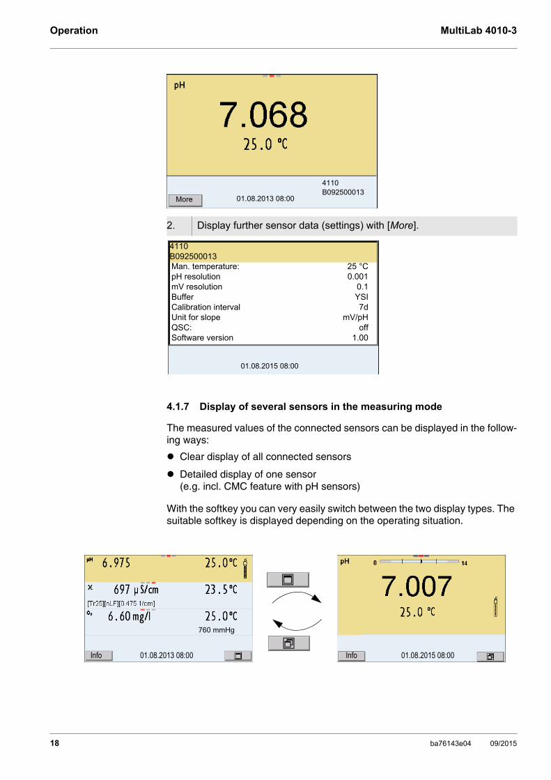
4.1.7 Display of several sensors in the measuring mode
The measured values of the connected sensors can be displayed in the follow-ing ways:
Clear display of all connected sensors
Detailed display of one sensor (e.g. incl. CMC feature with pH sensors)
With the softkey you can very easily switch between the two display types. The suitable softkey is displayed depending on the operating situation.
2. Display further sensor data (settings) with [More].
01.08.2013 08:00More
4110B092500013
01.08.2015 08:00
Man. temperature: 25 °CpH resolution 0.001mV resolution 0.1Buffer YSICalibration interval 7dUnit for slope mV/pHQSC: offSoftware version 1.00
4110B092500013
01.08.2013 08:00Info
760 mmHg
01.08.2015 08:00Info
18 ba76143e04 09/2015

MultiLab 4010-3 Operation
4.2 Switching on the meter
4.3 Switching off the meter
4.4 Login with user name
After activation of the user administration (see the MultiLab User operating manual) by the administrator, measurementsare only possible after login with a user name. The user name is documented with the measured values and in records.
All user names entered by the administrator are listed in the User name menu. The administrator determines for each user whether or not a password is required for the login to the meter.
If the Password menu item is grayed out, no password is required for the login.
1. Switch the meter on with <On/Off>.The meter performs a self-test.
2. Connect the sensor.The meter is ready to measure.
If the user administration function is activated, the Login dialog appears after the meter is switched on (see section 4.4 LOGIN WITH USER NAME, page 19).
The user administration function is not active in the delivery condi-tion.The user administration function is activated by the administrator via the MultiLab User PC software (see the MultiLab User operating manual).
1. Switch off the meter with <On/Off>.
1. Switch on the meter with <On/Off>.The Login dialog appears.
01.08.2013 08:00Info
ba76143e04 09/2015 19

Operation MultiLab 4010-3
Changing thepassword
If the administrator has set up the access with password protection:
2. Using <><>, select the menu item, User name and confirm with <ENTER>.The user name is highlighted.
3. Using <><>, select a user name and confirm with <ENTER>.
The login is done immediately if no password is required.If a sensor is connected the measured value display appears.
4. If a password is required:Using <><>, select the menu item, Password and confirm with <ENTER>.
The user specifies the password when he or she first logs in with a user name. A valid password consists of 4 digits. The user can change the password with the next login.
5. Change the digit of the highlighted position with <><>.Switch to the next position of the password with <><>.When the password was completely entered, confirm with <ENTER>. The login takes place. If a sensor is connected the measured value dis-play appears.
User name AdminPassword ####Change password
Login
01.08.2015 08:00
1. Switch on the meter with <On/Off>.The Login dialog appears.
2. Using <><>, select the menu item, User name and confirm with <ENTER>.The user name is highlighted.
3. Using <><>, select a user name and confirm with <ENTER>.
4. Using <><>, select the menu item, Change password and confirm with <ENTER>.
20 ba76143e04 09/2015
MultiLab 4010-3 Operation
Forgotten thepassword?
Contact the administrator.
4.5 Navigation
4.5.1 Operating modes
4.5.2 Measured value display
In the measured value display, you can
use <><> to select one of several connected sensors. The selected sensor is displayed with a colored background. The following actions / menus refer to the selected sensor
open the menu for calibration and measurement settings with <ENTER> (short keystroke)
open the Storage & config menu with the sensor-independent settings by pressing <ENTER_> (long keystroke, approx. 2 s).
change the display in the selected measuring screen (e. g. pH <−> mV) by pressing <M>.
4.5.3 Menus and dialogs
The menus for settings and dialogs in procedures contain further subelements.
5. In the Password field, enter the old password with <><> and <><>and confirm it with <ENTER>.
6. In the New password field, enter the new password with <><> and <><>and confirm it with <ENTER>.The password is changed. The login takes place. If a sensor is connected the measured value dis-play appears.
Operating mode
Explanation
Measuring The measurement data of the connected sensor are shown in the measured value display
Calibration The course of a calibration with calibration information, func-tions and settings is displayed
Storage in memory
The meter stores measuring data automatically or manually
Transmitting data
The meter transmits measuring data and calibration records to a USB interface automatically or manually.
Setting The system menu or a sensor menu with submenus, set-tings and functions is displayed
ba76143e04 09/2015 21
Operation MultiLab 4010-3
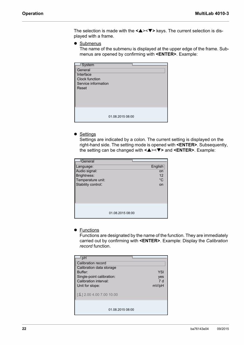
The selection is made with the <><> keys. The current selection is dis-played with a frame.
SubmenusThe name of the submenu is displayed at the upper edge of the frame. Sub-menus are opened by confirming with <ENTER>. Example:
SettingsSettings are indicated by a colon. The current setting is displayed on the right-hand side. The setting mode is opened with <ENTER>. Subsequently, the setting can be changed with <><> and <ENTER>. Example:
FunctionsFunctions are designated by the name of the function. They are immediately carried out by confirming with <ENTER>. Example: Display the Calibration record function.
GeneralInterfaceClock functionService informationReset
System
01.08.2015 08:00
Language: EnglishAudio signal: onBrightness: 12Temperature unit: °CStability control: on
General
01.08.2015 08:00
pH
01.08.2015 08:00
Calibration recordCalibration data storageBuffer: YSISingle-point calibration: yesCalibration interval: 7 dUnit for slope: mV/pH
[i] 2.00 4.00 7.00 10.00
22 ba76143e04 09/2015

MultiLab 4010-3 Operation
MessagesInformation is marked by the [i] symbol. It cannot be selected. Example:
4.5.4 Example 1 on navigation: Setting the language
1. Press the <On/Off> key.The measured value display appears.The instrument is in the measuring mode.
2. Open the Storage & config menu with <ENTER_>.The instrument is in the setting mode.
Calibration recordCalibration data storageBuffer: YSISingle-point calibration: yesCalibration interval: 7 dUnit for slope: mV/pH
[i] 2.00 4.00 7.00 10.00
pH
01.08.2015 08:00
01.08.2013 08:00Info
System Data storage
Storage & config
01.08.2015 08:00
ba76143e04 09/2015 23

Operation MultiLab 4010-3
3. Select the System submenu with <><>. The current selection is displayed with a frame.
4. Open the System submenu with <ENTER>.
5. Select the General submenu with <><>. The current selection is displayed with a frame.
6. Open the General submenu with <ENTER>.
7. Open the setting mode for the Language with <ENTER>.
8. Select the required language with <><>.
GeneralInterface Clock function Service information Reset
System
01.08.2015 08:00
Language: EnglishAudio signal: onBrightness: 12Temperature unit: °CStability control: on
General
01.08.2015 08:00
Language: EnglishAudio signal: onBrightness: 12Temperature unit: °CStability control: on
General
01.08.2015 08:00
24 ba76143e04 09/2015

MultiLab 4010-3 Operation
4.5.5 Example 2 on navigation: Setting the date and time
The meter has a clock with a date function. The date and time are indicated in the status line of the measured value display. When storing measured values and calibrating, the current date and time are automatically stored as well.
The correct setting of the date and time and date format is important for the fol-lowing functions and displays:
Current date and time
Calibration date
Identification of stored measured values.
Therefore, check the time at regular intervals.
Setting the date,time and date format
The date format can be switched from the display of day, month, year (dd.mm.yy) to the display of month, day, year (mm/dd/yy or mm.dd.yy).
9. Confirm the setting with <ENTER>. The meter switches to the measuring mode.The selected language is active.
The date and time are reset, if the following conditions are met:
the supply voltage failed and
the buffer batteries for the system clock are empty.
1. In the measured value display:Open the Storage & config menu with <ENTER_>.The instrument is in the setting mode.
2. Select and confirm the System / Clock function menu with <><> and <ENTER>.The setting menu for the date and time opens up.
3. Select and confirm the Time menu with <><> and <ENTER>.The hours are highlighted.
4. Change and confirm the setting with <><> and <ENTER>.The minutes are highlighted.
Date format: dd.mm.yyDate: 03.04.2013Time: 14:53:40
Clock function
01.08.2015 08:00
ba76143e04 09/2015 25

Operation MultiLab 4010-3
5. Change and confirm the setting with <><> and <ENTER>.The seconds are highlighted.
6. Change and confirm the setting with <><> and <ENTER>.The time is set.
7. If necessary, set the Date and Date format. The setting is made simi-larly to that of the time.
8. To make further settings, switch to the next higher menu level with <ESC>.orSwitch to the measured value display with <M>. The instrument is in the measuring mode.
26 ba76143e04 09/2015

MultiLab 4010-3 pH value
5 pH value
5.1 Measuring
5.1.1 Measuring the pH value
Stability control(AutoRead)
& HOLD function
The stability control function (AutoRead) continually checks the stability of the measurement signal. The stability has a considerable impact on the reproduc-ibility of measured values.
The measured parameter flashes on the display
as soon as the measured value is outside the stability range
when the automatic Stability control is switched off.
You can start the Stability control manually at any time, irrespective of the set-ting for automatic Stability control (see section 10.6.3 AUTOMATIC STABILITY CONTROL, page 96) in the System menu.
The sensor connection and the USB-B (device) interface are gal-vanically isolated. This facilitates interference-free measurements also in the following cases:
Measurement in grounded test samples
Measurement with several sensors connected to one MultiLab 4010-3 in one test sample
1. Connect the IDS pH sensor to the meter.The pH measuring window is displayed.
2. If necessary, select the measured parameter with <M>.
3. Adjust the temperature of the solutions and measure the current tem-perature if the measurement is made without a temperature sensor.
4. If necessary, calibrate or check the IDS pH sensor.
5. Immerse the IDS pH sensor in the test sample.
01.08.2015 08:00Info
1. Freeze the measured value with <AR>.The [HOLD] status indicator is displayed. The HOLD function is active.
ba76143e04 09/2015 27
pH value MultiLab 4010-3
Criteria for a stablemeasured value
The Stability control function checks whether the measured values are stable within the monitored time interval.
The minimum duration until a measured value is assessed as stable is the monitored time interval. The actual duration is mostly longer.
5.1.2 Measuring the temperature
For reproducible pH measurements, it is essential to measure the temperature of the test sample.
IDS sensors measure the temperature with a temperature sensor integrated in the IDS sensor.
When operating a sensor without integrated temperature sensor, e.g.via an IDS pH adapter, you have to measure and enter the temperature of the test sample first.
You can terminate the Stability control function and the HOLD func-tion with <AR> or <M> at any time.
2. Using <ENTER>, activate the Stability control function manually.The [AR] status indicator appears while the measured value is assessed as not stable. A progress bar is displayed and the display of the mea-sured parameter flashes.As soon as a measured value meets the stability criteria, it is frozen. The [HOLD][AR] status indicator is displayed, the progress bar disappears and the display of the measured parameter stops flashing. The current measurement data is output to the interface. Measurement data meeting the stability control criterion is marked by AR.
You can prematurely terminate the Stability control function manu-ally with <ENTER> at any time. When the Stability control function is prematurely terminated, the current measurement data are out-put to the interface (PC, USB memory device or USB printer) with-out AutoRead info.
3. Using <ENTER>, start a further measurement with stability control.orRelease the frozen measured value again with <AR> or <M>.The [AR] status display disappears. The display switches back to the pre-vious indication.
Measured parameter
Time interval Stability in the time interval
pH value 15 seconds ∆ : Better than 0.01 pH
Temperature 15 seconds ∆ : Better than 0.5 °C
28 ba76143e04 09/2015

MultiLab 4010-3 pH value
The display of the temperature indicates the active temperature measuring mode:
5.2 pH calibration
5.2.1 Why calibrate?
pH electrodes age. This changes the zero point (asymmetry) and slope of the pH electrode. As a result, an inexact measured value is displayed. Calibration determines and stores the current values of the zero point and slope of the electrode. Thus, you should calibrate at regular intervals.
5.2.2 When do you have to calibrate?
Routinely within the framework of the company quality assurance
When the calibration interval has expired
5.2.3 Carrying out automatic calibration (AutoCal)
Make sure that in the sensor menu, Buffer menu, the buffer set is correctly selected (see section 10.1.1 SETTINGS FOR PH MEASUREMENTS, page 83).
Use one to five buffer solutions of the selected buffer set in any order.
Below, calibration with YSI buffers (YSI) is described. When other buffer sets are used, other nominal buffer values are displayed. Apart from that, the proce-dure is identical.
Temperature sensor
Resolution of the temp. display
Temp. measurement
Yes 0.1 °C Automatic with temperature sensor
- 1 °C Manual
If single-point calibration was set in the menu, the calibration proce-dure is automatically finished with the measurement of buffer solu-tion 1 and the calibration record is displayed.
1. Connect the pH sensor to the meter.The pH measuring window is displayed.
2. Keep the buffer solutions ready. When measuring without temperature sensor: Temper the buffer solutions or measure the current temperature.
3. Start the calibration with <CAL>.The calibration display for the first buffer appears (voltage display).
ba76143e04 09/2015 29
pH value MultiLab 4010-3
Continuing with two-point calibration
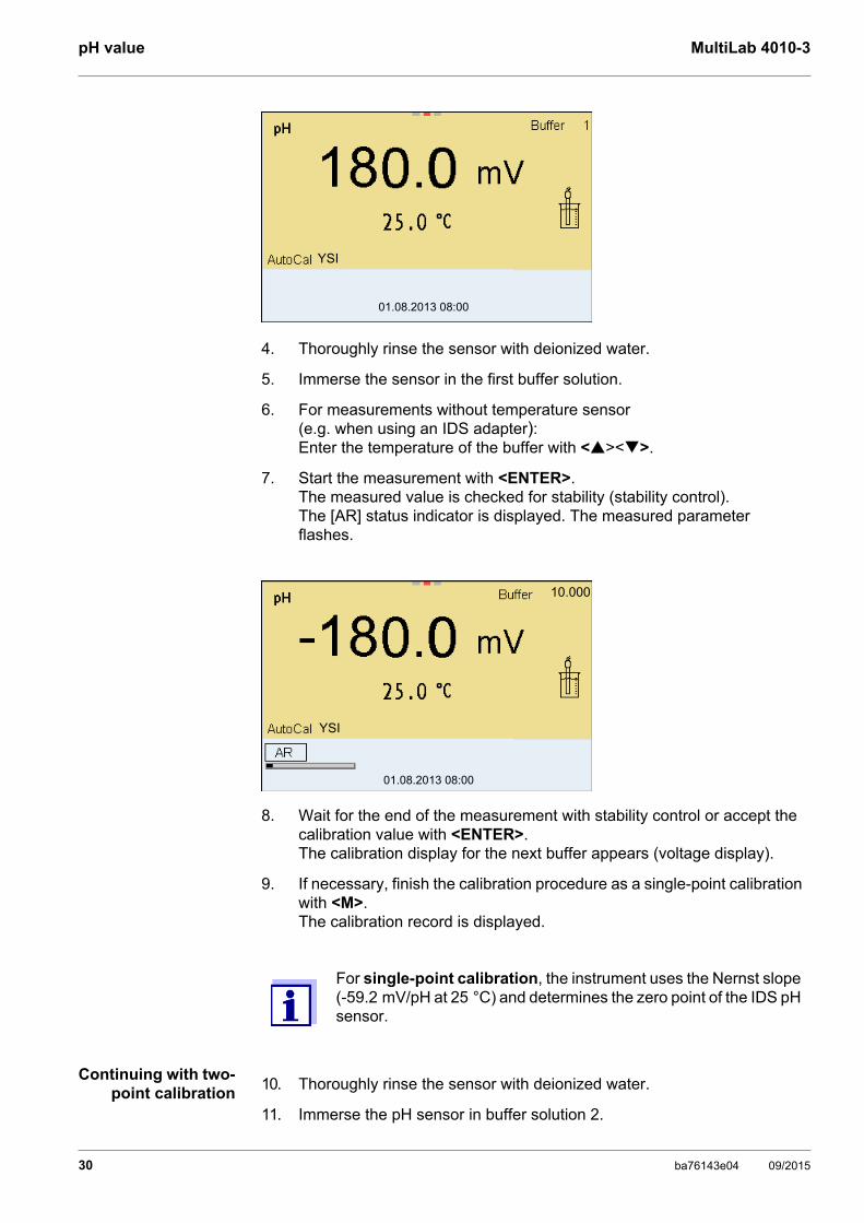
4. Thoroughly rinse the sensor with deionized water.
5. Immerse the sensor in the first buffer solution.
6. For measurements without temperature sensor (e.g. when using an IDS adapter):Enter the temperature of the buffer with <><>.
7. Start the measurement with <ENTER>.The measured value is checked for stability (stability control).The [AR] status indicator is displayed. The measured parameter flashes.
8. Wait for the end of the measurement with stability control or accept the calibration value with <ENTER>. The calibration display for the next buffer appears (voltage display).
9. If necessary, finish the calibration procedure as a single-point calibration with <M>.The calibration record is displayed.
For single-point calibration, the instrument uses the Nernst slope (-59.2 mV/pH at 25 °C) and determines the zero point of the IDS pH sensor.
01.08.2013 08:00
YSI
01.08.2013 08:00
YSI
10.000
10. Thoroughly rinse the sensor with deionized water.
11. Immerse the pH sensor in buffer solution 2.
30 ba76143e04 09/2015

MultiLab 4010-3 pH value
Continuing withthree- to five-point
calibration
12. When measuring without temperature sensor:Enter the temperature of the buffer with <><>.
13. Start the measurement with <ENTER>.The measured value is checked for stability (stability control).The [AR] status indicator is displayed. The measured parameter flashes.
14. Wait for the measurement with stability control to be completed or termi-nate the stability control and take over the calibration value with <ENTER>. The calibration display for the next buffer appears (voltage display).
15. If necessary, finish the calibration procedure as a two-point calibration with <M>.The calibration record is displayed.
01.08.2013 08:00
YSI
16. Thoroughly rinse the sensor with deionized water.
17. Immerse the sensor in the next buffer solution.
18. When measuring without temperature sensor:Enter the temperature of the buffer with <><>.
19. Start the measurement with <ENTER>.The measured value is checked for stability (stability control).The [AR] status indicator is displayed. The measured parameter flashes.
ba76143e04 09/2015 31

pH value MultiLab 4010-3
5.2.4 Carrying out a manual calibration (ConCal)
Make sure that in the sensor menu, Buffer menu, the ConCal buffer set is correctly selected (see section 10.1.1 SETTINGS FOR PH MEASUREMENTS, page 83).
Use any one to five buffer solutions in ascending or descending order.
20. Wait for the measurement with stability control to be completed or termi-nate the stability control and take over the calibration value with <ENTER>. The calibration display for the next buffer appears (voltage display).
21. If necessary, use <M> to finish the calibration.The calibration record is displayed. or Switch to calibration with the next buffer with <ENTER>.
Calibration is automatically completed after the last buffer of a buf-fer set has been measured. Then the calibration record is dis-played.
The calibration line is determined by linear regression.
If single-point calibration was set in the menu, the calibration proce-dure is automatically finished with the measurement of buffer solu-tion 1 and the calibration record is displayed.
1. Connect the pH sensor to the meter.The pH measuring window is displayed.
2. Keep the buffer solutions ready. When measuring without temperature sensor: Temper the buffer solutions or measure the current temperature.
3. Start the calibration with <CAL>.The calibration display for the first buffer appears (voltage display).
01.08.2013 08:00
YSI
4.000
32 ba76143e04 09/2015
MultiLab 4010-3 pH value
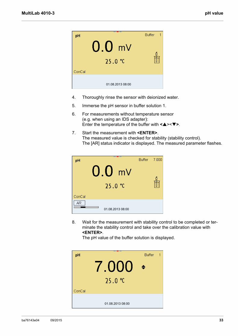
4. Thoroughly rinse the sensor with deionized water.
5. Immerse the pH sensor in buffer solution 1.
6. For measurements without temperature sensor (e.g. when using an IDS adapter):Enter the temperature of the buffer with <><>.
7. Start the measurement with <ENTER>.The measured value is checked for stability (stability control).The [AR] status indicator is displayed. The measured parameter flashes.
8. Wait for the measurement with stability control to be completed or ter-minate the stability control and take over the calibration value with <ENTER>. The pH value of the buffer solution is displayed.
01.08.2013 08:00
01.08.2013 08:00
01.08.2013 08:00
ba76143e04 09/2015 33

pH value MultiLab 4010-3
Continuing with two-point calibration
9. Set the nominal buffer value for the measured temperature with <><>.
10. Accept the calibration value with <ENTER>. The calibration display for the next buffer appears (voltage display).
11. If necessary, finish the calibration procedure as a single-point calibration with <M>.The calibration record is displayed.
For single-point calibration, the instrument uses the Nernst slope (-59.2 mV/pH at 25 °C) and determines the zero point of the IDS pH sensor.
12. Thoroughly rinse the sensor with deionized water.
13. Immerse the pH sensor in buffer solution 2.
14. When measuring without temperature sensor:Enter the temperature of the buffer with <><>.
15. Start the measurement with <ENTER>.The measured value is checked for stability (stability control).The [AR] status indicator is displayed. The measured parameter flashes.
16. Wait for the measurement with stability control to be completed or ter-minate the stability control and take over the calibration value with <ENTER>. The pH value of the buffer solution is displayed.
17. Set the nominal buffer value for the measured temperature with <><>.
18. Accept the calibration value with <ENTER>. The calibration display for the next buffer appears (voltage display).
19. If necessary, finish the calibration procedure as a two-point calibration with <M>.The calibration record is displayed.
01.08.2013 08:00
34 ba76143e04 09/2015
MultiLab 4010-3 pH value
Continuing withthree- to five-point
calibration
5.2.5 Calibration points
Calibration can be performed using one to five buffer solutions in any order (single-point to five-point calibration). The meter determines the following values and calculates the calibration line as follows:
20. Thoroughly rinse the sensor with deionized water.
21. Immerse the sensor in the next buffer solution.
22. When measuring without temperature sensor:Enter the temperature of the buffer with <><>.
23. Start the measurement with <ENTER>.The measured value is checked for stability (stability control).The [AR] status indicator is displayed. The measured parameter flashes.
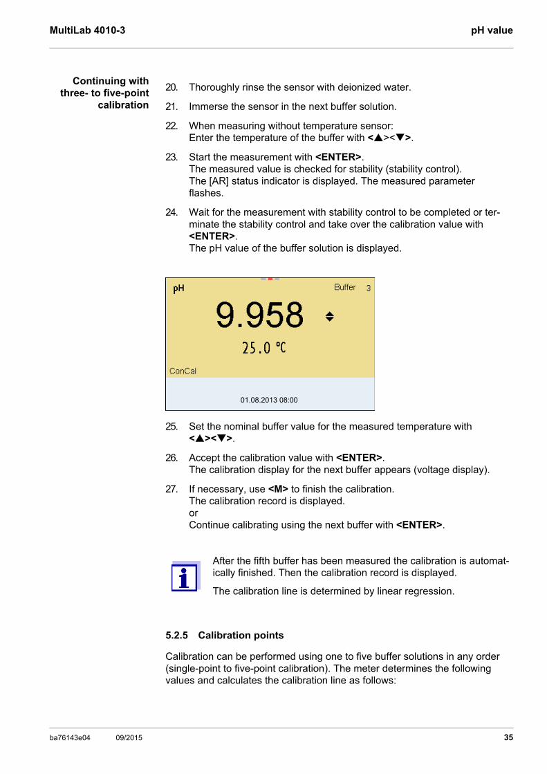
24. Wait for the measurement with stability control to be completed or ter-minate the stability control and take over the calibration value with <ENTER>. The pH value of the buffer solution is displayed.
25. Set the nominal buffer value for the measured temperature with <><>.
26. Accept the calibration value with <ENTER>. The calibration display for the next buffer appears (voltage display).
27. If necessary, use <M> to finish the calibration.The calibration record is displayed. or Continue calibrating using the next buffer with <ENTER>.
After the fifth buffer has been measured the calibration is automat-ically finished. Then the calibration record is displayed.
The calibration line is determined by linear regression.
01.08.2013 08:00
ba76143e04 09/2015 35

pH value MultiLab 4010-3
5.2.6 Calibration data
Displaying the cali-bration data
The calibration record of the last calibration is to be found under the menu item, Calibration / Calibration record. To open it in the measured value display, press the <CAL_> key.
The calibration records of the last 10 calibrations are to be found in the menu, Calibration / Calibration data storage / Display. To open the Calibration menu, press the <ENTER> key in the measured value display.
Calibration Determined val-ues
Displayed calibration data
1-point Asy Zero point = Asy
Slope = Nernst slope (-59.2 mV/pH at 25 °C)
2-point AsySlp.
Zero point = Asy
Slope = Slp.
3-point to 5-point
AsySlp.
Zero point = Asy
Slope = Slp.
The calibration line is calculated by linear regression.
You can display the slope in the units, mV/pH or % (see section 10.1.1 SETTINGS FOR PH MEASUREMENTS, page 83).
The calibration record is automatically transmitted to the interface after calibrating.
36 ba76143e04 09/2015
MultiLab 4010-3 pH value
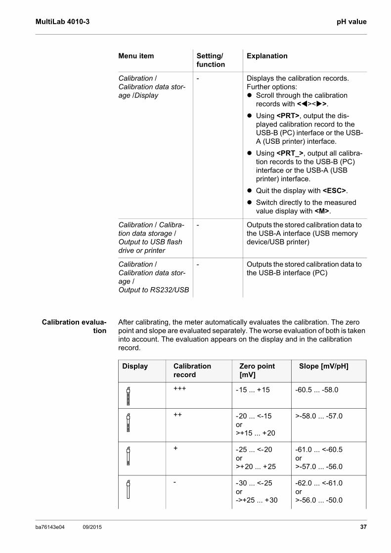
Calibration evalua-tion
After calibrating, the meter automatically evaluates the calibration. The zero point and slope are evaluated separately. The worse evaluation of both is taken into account. The evaluation appears on the display and in the calibration record.
Menu item Setting/function
Explanation
Calibration / Calibration data stor-age /Display
- Displays the calibration records.Further options: Scroll through the calibration
records with <><>.
Using <PRT>, output the dis-played calibration record to the USB-B (PC) interface or the USB-A (USB printer) interface.
Using <PRT_>, output all calibra-tion records to the USB-B (PC) interface or the USB-A (USB printer) interface.
Quit the display with <ESC>.
Switch directly to the measured value display with <M>.
Calibration / Calibra-tion data storage / Output to USB flash drive or printer
- Outputs the stored calibration data to the USB-A interface (USB memory device/USB printer)
Calibration / Calibration data stor-age / Output to RS232/USB
- Outputs the stored calibration data to the USB-B interface (PC)
Display Calibration record
Zero point [mV]
Slope [mV/pH]
+++ -15 ... +15 -60.5 ... -58.0
++ -20 ... <-15or>+15 ... +20
>-58.0 ... -57.0
+ -25 ... <-20or>+20 ... +25
-61.0 ... <-60.5or>-57.0 ... -56.0
- -30 ... <-25or->+25 ... +30
-62.0 ... <-61.0or>-56.0 ... -50.0
ba76143e04 09/2015 37
pH value MultiLab 4010-3
Calibration record
5.2.7 Continuous measurement control (CMC function)
The Continuous Measurement Control (CMC function) facilitates to evaluate the current measured value instantly and definitely.
After each successful calibration the scale of the pH measuring range is displayed in the measured value display. Here you can very clearly see whether or not the current measured value is in the calibrated part of the measuring range.
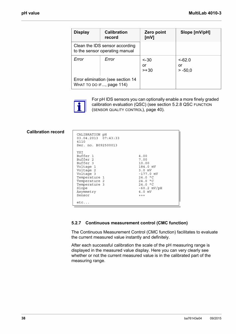
Clean the IDS sensor according to the sensor operating manual
Error Error <-30or >+30
<-62.0 or> -50,0
Error elimination (see section 14 WHAT TO DO IF..., page 114)
For pH IDS sensors you can optionally enable a more finely graded calibration evaluation (QSC) (see section 5.2.8 QSC FUNCTION (SENSOR QUALITY CONTROL), page 40).
Display Calibration record
Zero point [mV]
Slope [mV/pH]
CALIBRATION pH03.04.2013 07:43:334110Ser. no. B092500013
YSIBuffer 1 4.00Buffer 2 7.00Buffer 3 10.00Voltage 1 184.0 mVVoltage 2 3.0 mVVoltage 3 -177.0 mVTemperature 1 24.0 °CTemperature 2 24.0 °CTemperature 3 24.0 °CSlope -60.2 mV/pHAsymmetry 4.0 mVSensor +++
etc...
38 ba76143e04 09/2015

MultiLab 4010-3 pH value
The following information is displayed:
The limits of the calibrated range are determined by the buffers used for cali-bration:
1 Currently measured pH value (needle)
2 Marking lines for all nominal buffer values used with the last valid cali-bration
3 Measuring range for which a valid calibration is available. Measured values in this range are suitable for documentation.
4 Measuring range for which no valid calibration is available (dark gray). Measured values in this range are not suitable for documenta-tion. Calibrate the meter with buffers covering this measuring range.If the current measured value is outside the calibrated range, this area is displayed in a darker gray.If a measured value is outside the measuring range pH 0 - 14, over-flow arrows are displayed at the left or right edge of the measuring range.
Lower limit: Buffer with lowest pH value - 2 pH units Upper limit: Buffer with highest pH value + 2 pH units
1
2
3
4
01.08.2013 08:00Info
ba76143e04 09/2015 39
pH value MultiLab 4010-3
5.2.8 QSC function (sensor quality control)
General informationon the QSC function
The QSC function (Quality Sensor Control) is a new sensor evaluation for digital IDS sensors. It evaluates the condition of an IDS pH sensor individually and with a very fine grading.
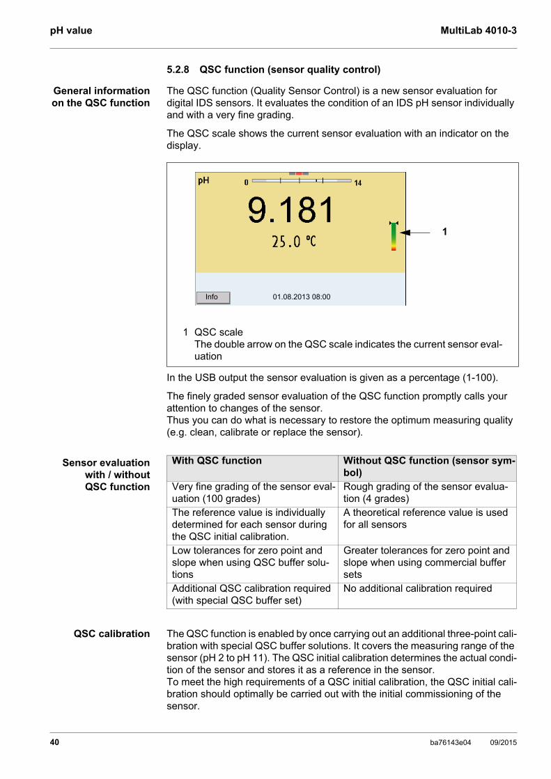
The QSC scale shows the current sensor evaluation with an indicator on the display.
In the USB output the sensor evaluation is given as a percentage (1-100).
The finely graded sensor evaluation of the QSC function promptly calls your attention to changes of the sensor. Thus you can do what is necessary to restore the optimum measuring quality (e.g. clean, calibrate or replace the sensor).
Sensor evaluationwith / withoutQSC function
QSC calibration The QSC function is enabled by once carrying out an additional three-point cali-bration with special QSC buffer solutions. It covers the measuring range of the sensor (pH 2 to pH 11). The QSC initial calibration determines the actual condi-tion of the sensor and stores it as a reference in the sensor. To meet the high requirements of a QSC initial calibration, the QSC initial cali-bration should optimally be carried out with the initial commissioning of the sensor.
1 QSC scaleThe double arrow on the QSC scale indicates the current sensor eval-uation
01.08.2013 08:00Info
1
With QSC function Without QSC function (sensor sym-bol)
Very fine grading of the sensor eval-uation (100 grades)
Rough grading of the sensor evalua-tion (4 grades)
The reference value is individually determined for each sensor during the QSC initial calibration.
A theoretical reference value is used for all sensors
Low tolerances for zero point and slope when using QSC buffer solu-tions
Greater tolerances for zero point and slope when using commercial buffer sets
Additional QSC calibration required (with special QSC buffer set)
No additional calibration required
40 ba76143e04 09/2015

MultiLab 4010-3 pH value
Carry out the normal calibrations for your special measuring range with your usual standard solutions as previously done.
Carrying out a QSCinitial calibration
The QSC initial calibration is completed. The sensor is calibrated. If you want to calibrate with special buffers for your measurements, you can subsequently carry out a normal calibration with your buffers. The reference values deter-mined with the QSC calibration are also used for the evaluation of normal cali-brations. In the measured value display, the QSC scale of the QSC function is always displayed. A double arrow on the QSC scale indicates the current sen-
As soon as the QSC function was enabled for an IDS sensor, it is not possible to return to the sensor evaluation with the sensor symbol for this sensor.
1. Open the menu for measurement settings with <ENTER>.
2. In the QSC menu, select First calibration with <><>.The calibration display appears. AutoCal QSC-Kit is displayed as the buffer.Exclusively use the QSC-Kit for the QSC calibration. If you use other buffers, you will have no valid QSC calibration.
3. Calibration with the buffers of the QSC-Kit is done like a normal three-point calibration.Follow the user guide.
Carry out the QSC initial calibration very carefully. It determines the reference value for the sensor. This reference value cannot be overwritten or reset.As soon as the QSC function was enabled, it is not possible to return to the sensor evaluation with the sensor symbol.
4. As soon as the three-point calibration has been successfully carried out you can decide whether to accept or discard the calibration as the QSC initial calibration.
01.08.2013 08:00
ba76143e04 09/2015 41

pH value MultiLab 4010-3
sor evaluation.
Carrying out a QSCcontrol calibration
A QSC control calibration can, e.g. be useful if the sensor evaluation noticeably changed (after some normal calibrations).
You can carry out QSC control calibrations at greater intervals than normal cali-brations.
1 QSC scaleThe double arrow on the QSC scale indicates the current sensor eval-uation
01.08.2013 08:00Info
1
1. Open the menu for measurement settings with <ENTER>.
2. In the QSC menu, select Control calibration with <><>.The calibration display appears. AutoCal QSC-Kit is displayed as the buf-fer.Exclusively use the QSC-Kit for the QSC calibration. If you use other buf-fers, you will have no valid QSC control calibration.
3. Follow the user guide.The calibration is carried out like a normal three-point calibration. As soon as the three-point calibration has been successfully carried out you can decide whether to accept or discard the calibration as the QSC control calibration.
42 ba76143e04 09/2015

MultiLab 4010-3 ORP voltage
6 ORP voltage
6.1 Measuring
6.1.1 Measuring the ORP
Stability control(AutoRead)
& HOLD function
The stability control function (AutoRead) continually checks the stability of the measurement signal. The stability has a considerable impact on the reproduc-ibility of measured values.
The measured parameter flashes on the display
as soon as the measured value is outside the stability range
when the automatic Stability control is switched off.
You can start the Stability control manually at any time, irrespective of the setting for automatic Stability control (see section 10.6.3 AUTOMATIC STABILITY CONTROL, page 96) in the System menu.
The sensor connection and the USB-B (device) interface are gal-vanically isolated. This facilitates interference-free measurements also in the following cases:
Measurement in grounded test samples
Measurement with several sensors connected to one MultiLab 4010-3 in one test sample
IDS ORP sensors are not calibrated. However, you can check IDS ORP sensors using a test solution.
1. Connect the ORP sensor to the meter.The ORP measuring window is displayed.
2. Adjust the temperature of the solutions and measure the current tem-perature if the measurement is made without a temperature sensor.
3. Check the meter with the ORP sensor.
4. Immerse the ORP sensor in the test sample.
01.08.2013 08:00Info
ba76143e04 09/2015 43

ORP voltage MultiLab 4010-3
Criteria for a stablemeasured value
The Stability control function checks whether the measured values are stable within the monitored time interval.
The minimum duration until a measured value is assessed as stable is the monitored time interval. The actual duration is mostly longer.
6.1.2 Measuring the relative ORP
To measure the difference of the ORPs of two solutions, you have to define the ORP of one solution as the zero point first.
1. Freeze the measured value with <AR>.The [HOLD] status indicator is displayed. The HOLD function is active.
You can terminate the Stability control function and the HOLD func-tion with <AR> or <M> at any time.
2. Using <ENTER>, activate the Stability control function manually.The [AR] status indicator appears while the measured value is assessed as not stable. A progress bar is displayed and the display of the mea-sured parameter flashes.As soon as a measured value meets the stability criteria, it is frozen. The [HOLD][AR] status indicator is displayed, the progress bar disappears and the display of the measured parameter stops flashing. The current measurement data is output to the interface. Measurement data meeting the stability control criterion is marked by AR.
You can prematurely terminate the Stability control function manu-ally with <ENTER> at any time. When the Stability control function is prematurely terminated, the current measurement data are out-put to the interface (PC, USB memory device or USB printer) with-out AutoRead info.
3. Using <ENTER>, start a further measurement with stability control.orRelease the frozen measured value again with <AR> or <M>.The [AR] status display disappears. The display switches back to the pre-vious indication.
Measured parameter
Time interval Stability in the time interval
ORP 15 seconds ∆ : Better than 0.3 mV
Temperature 15 seconds ∆ : Better than 0.5 °C
44 ba76143e04 09/2015

MultiLab 4010-3 ORP voltage
AutoRead The Stability control function checks whether the measured values are stable within the monitored time interval.
The minimum duration until a measured value is assessed as stable is the monitored time interval. The actual duration is mostly longer.
ORP electrodes can be used to determine the relative ORP.
1. Connect the ORP electrode to the meter.
2. Prepare the reference solution for the determination of the reference point.
3. Select the ΔU (mV display with <M>.
4. Immerse the ORP electrode in the reference solution.
5. Display the potential of the current zero point with <CAL>.
6. Press <ENTER> to measure the reference solution.The measured value is checked for stability (automatic stability con-trol). The display of the measured parameter flashes.The measured potential is defined as the zero point.orPress <M> to terminate the display of the zero point.
7. Rinse the ORP electrode and immerse it in the test sample.The measured value is checked for stability (automatic stability con-trol). The display of the measured parameter flashes.
8. Wait for a stable measured value.The display of the measured parameter no longer flashes.
01.08.2013 08:00Info
Measured parame-ter
Time interval Stability in the time interval
ORP 15 seconds ∆ : better than 0.3 mV
Temperature 15 seconds ∆ : better than 0.5 °C
ba76143e04 09/2015 45
ORP voltage MultiLab 4010-3
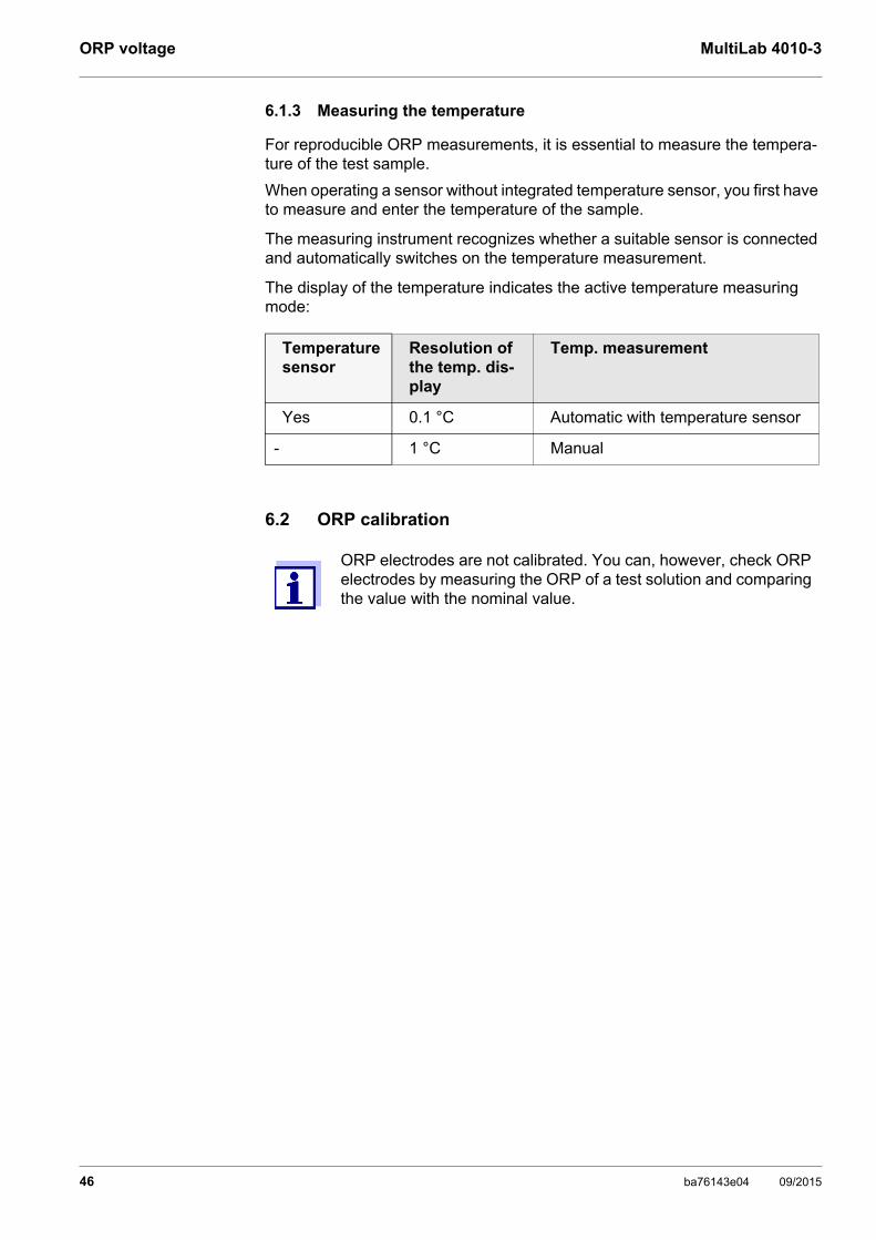
6.1.3 Measuring the temperature
For reproducible ORP measurements, it is essential to measure the tempera-ture of the test sample.
When operating a sensor without integrated temperature sensor, you first have to measure and enter the temperature of the sample.
The measuring instrument recognizes whether a suitable sensor is connected and automatically switches on the temperature measurement.
The display of the temperature indicates the active temperature measuring mode:
6.2 ORP calibration
Temperaturesensor
Resolution of the temp. dis-play
Temp. measurement
Yes 0.1 °C Automatic with temperature sensor
- 1 °C Manual
ORP electrodes are not calibrated. You can, however, check ORP electrodes by measuring the ORP of a test solution and comparing the value with the nominal value.
46 ba76143e04 09/2015

MultiLab 4010-3 Ion concentration
7 Ion concentration
7.1 Measuring
7.1.1 Measuring the ion concentration
The sensor connection and the USB-B (device) interface are gal-vanically isolated. This facilitates interference-free measurements also in the following cases:
Measurement in grounded test samples
Measurement with several sensors connected to one MultiLab 4010-3 in one test sample
Incorrect calibration of ion selective electrodes will result in incor-rect measured values. Calibrate regularly before measuring.
For precise ISE measurements the temperature difference between measurement and calibration should not be greater that 2 K. Therefore, adjust the temperature of the standard and measuring solutions accordingly. If the temperature difference is greater the [TpErr] warning appears in the measured value display.
1. Connect the ISE combination electrode to the meter with the aid of an ADA 94/IDS adapter.The pH/ISE measuring window is displayed.
2. In the measured value display, select the ISE measuring window with <> <> and <M>.
3. If necessary, change the ion type in the ISE setup/Ion type menu.
4. If necessary, measure the temperature of the test sample with a ther-mometer.
5. Calibrate or check the meter with the electrode.
While no valid calibration is available, e.g. in the delivery condition, "Error" appears in the measured value display.
6. Immerse the electrode in the test sample.
ba76143e04 09/2015 47

Ion concentration MultiLab 4010-3
Stability control(AutoRead)
& HOLD function
The stability control function (AutoRead) continually checks the stability of the measurement signal. The stability has a considerable impact on the reproduc-ibility of measured values.
The measured parameter flashes on the display
as soon as the measured value is outside the stability range
when the automatic Stability control is switched off.
You can activate or switch off the automatic Stability control function (see section 10.6.3 AUTOMATIC STABILITY CONTROL, page 96).
01.08.2015 08:00
1. Freeze the measured value with <AR>.The [HOLD] status indicator is displayed. The HOLD function is active.
You can terminate the Stability control function and the HOLD func-tion with <AR> or <M> at any time.
2. Using <ENTER>, activate the Stability control function manually.The [AR] status indicator appears while the measured value is assessed as not stable. A progress bar is displayed and the display of the measured parameter flashes.The [HOLD][AR] status indicator appears as soon as a stable mea-sured value is recognized. The progress bar disappears and the dis-play of the measured parameter stops flashing. The current measurement data is output to the interface. Measurement data meeting the stability control criterion is marked by AR.
You can prematurely terminate the Stability control function manu-ally with <ENTER> at any time. If the Stability control function is prematurely terminated, the current measurement data are output to the interface without the AutoRead info.
48 ba76143e04 09/2015

MultiLab 4010-3 Ion concentration
Criteria The AutoRead criteria affect the reproducibility of the measured values. The following criteria can be adjusted:
high: highest reproducibility
medium: medium reproducibility
low: lowest reproducibility
7.1.2 Measuring the temperature
For reproducible ion-selective measurements, it is essential to measure the temperature of the test sample. You have the following options to measure the temperature:
Measurement by an external temperature sensor.
Manual determination and input of the temperature.
The measuring instrument recognizes whether a suitable sensor is connected and automatically switches on the temperature measurement.
The display of the temperature indicates the active temperature measuring mode:
If you wish to measure (or calibrate) without temperature sensor, proceed as follows:
3. Using <ENTER>, start a further measurement with stability control.orRelease the frozen measured value again with <AR> or <M>.The [AR] status display disappears. The display switches back to the previous indication.
Increasing reproducibility also causes the response time to increase until a measured value is evaluated as stable.
Temperature sensor
Resolution of the temp. display Temp. measurement
yes 0.1 °C Automatic with temperature sensor
- 1 °C Manual
1. Measure the current temperature of the test sample.
2. Set the temperature value with <><>.orIn the <ENTER>/ISE/Man. temperature menu, set the temperature value with <><>.
ba76143e04 09/2015 49

Ion concentration MultiLab 4010-3
7.2 Calibration
7.2.1 Why calibrate?
Ion-selective electrodes age and are temperature-dependent. This changes the slope. As a result, an inexact measured value is displayed. Calibration determines the calibration line of the electrode and stores this value in the meter.Thus, you should calibrate before each measurement and at regular intervals.
7.2.2 When to calibrate?
Before any measurement if possible
After connecting another ISE electrode
7.2.3 Calibration (ISE Cal)
ISE Cal is the conventional two-point to seven-point calibration procedure that uses 2 to 7 freely selectable standard solutions. The concentration expected for the measurement determines the concentration of the calibration standards.
1. Connect the ISE combination electrode to the meter.The pH/mV/ISE measuring window is displayed.
2. Keep the standard solutions ready.
3. If necessary, measure the temperature of the standard solutions with a thermometer.
4. In the measured value display, select the ISE measuring window with <> <> and <M>.
5. If necessary, change the ion type in the ISE setup/Ion type menu.
6. If necessary, change the unit of the measurement result and calibration standards in the ISE setup/Unit menu.
7. Start the calibration with <CAL>.The calibration display appears.
8. Thoroughly rinse the electrode with distilled water.
01.08.2015 08:00
Standard
50 ba76143e04 09/2015
MultiLab 4010-3 Ion concentration
Continuing with two-point calibration
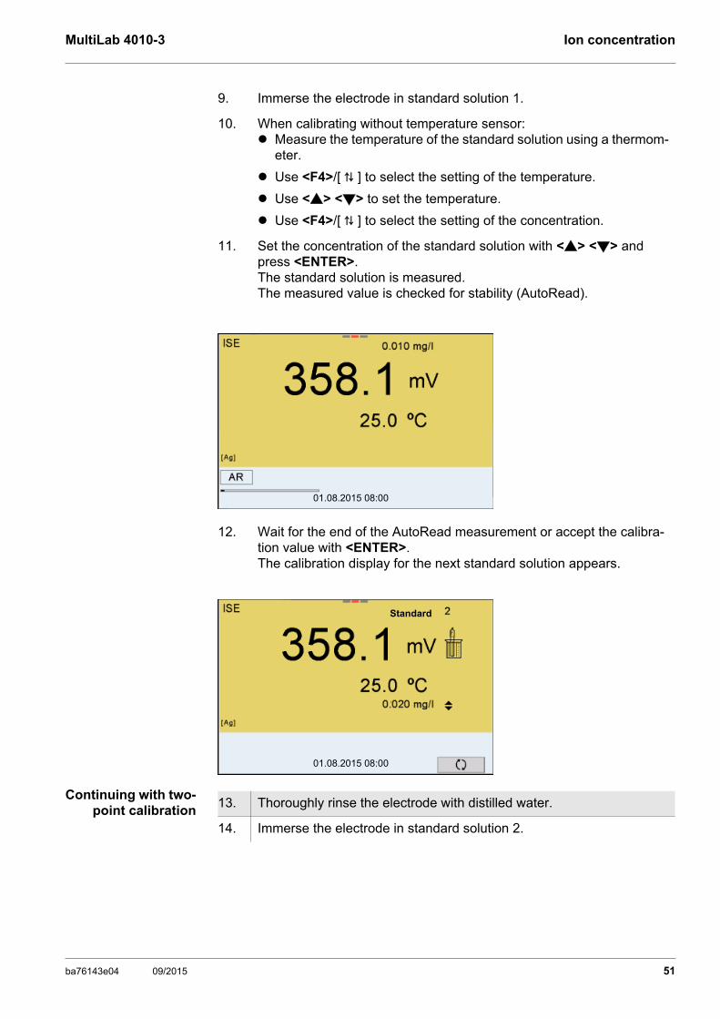
9. Immerse the electrode in standard solution 1.
10. When calibrating without temperature sensor: Measure the temperature of the standard solution using a thermom-
eter.
Use <F4>/[ ⇅ ] to select the setting of the temperature.
Use <> <> to set the temperature.
Use <F4>/[ ⇅ ] to select the setting of the concentration.
11. Set the concentration of the standard solution with <> <> and press <ENTER>.The standard solution is measured.The measured value is checked for stability (AutoRead).
12. Wait for the end of the AutoRead measurement or accept the calibra-tion value with <ENTER>. The calibration display for the next standard solution appears.
01.08.2015 08:00
01.08.2015 08:00
Standard
13. Thoroughly rinse the electrode with distilled water.
14. Immerse the electrode in standard solution 2.
ba76143e04 09/2015 51

Ion concentration MultiLab 4010-3
Continuing withthree- to seven-point
calibration
Repeat the steps 8 to 13 in the same way with the third and further standard solutions as necessary. The new calibration values are displayed after the last calibration step was completed.
15. When calibrating without temperature sensor: Measure the temperature of the standard solution using a thermom-
eter.
Use <F4>/[ ⇅ ] to select the setting of the temperature.
Use <> <> to set the temperature.
Use <F4>/[ ⇅ ] to select the setting of the concentration.
16. Set the concentration of the standard solution with <> <> and press <ENTER>.The standard solution is measured.The measured value is checked for stability (AutoRead).
17. Wait for the end of the AutoRead measurement or accept the calibra-tion value with <ENTER>. The calibration display for the next standard solution appears.
18. Press <ENTER> to continue with three-point calibration.orFinish the calibration procedure as a two-point calibration with <M>.The new calibration values are displayed.
01.08.2015 08:00
01.08.2015 08:00
Standard
Based on the calibration data, the calibration curve is determined in sections, according to the Nernst equation modified by Nikolski.
52 ba76143e04 09/2015

MultiLab 4010-3 Ion concentration
7.2.4 Calibration standards
Use two to seven different standard solutions. The standard solutions have to be selected in either increasing or decreasing order.
7.2.5 Calibration data
Displaying the cali-bration data
The calibration record of the last calibration is to be found under the menu item, Calibration / Calibration record. To open it in the measured value display, press the <CAL_> key.
The calibration records of the last 10 calibrations are to be found in the menu, Calibration / Calibration data storage / Display. To open the Calibration menu, press the <ENTER> key in the measured value display.
Select the unit of the standard solution and measurement result in the ISE setup/Unit menu.
Standard solution (Std 1 - 7) Values
Unit [mg/l] 0.010 ... 500,000
Unit [mol/l] 0.100 ... 5,000 µmol/l10.00 ... 5,000 mmol/l
Unit [mg/kg] 0.010 ... 500,000
Unit [ppm] 0.010 ... 500,000
Unit [%] 0.001 ... 50,000
The measurement precision is also dependent on the selected standard solutions. Therefore, the selected standard solutions should cover the value range expected of the subsequent concen-tration measurement.
If the measured electrode potential is outside the calibrated range, the [ISEErr] warning is displayed.
The calibration record is automatically transmitted to the interface after calibrating.
ba76143e04 09/2015 53

Ion concentration MultiLab 4010-3
Calibrationevaluation
After calibrating, the meter automatically evaluates the calibration.
Menu item Setting/function
Explanation
Calibration / Calibration data stor-age /Display
- Displays the calibration records.Further options: Scroll through the calibration
records with <><>.
Using <PRT>, output the dis-played calibration record to the USB-B (PC) interface or the USB-A (USB printer) interface.
Using <PRT_>, output all calibra-tion records to the USB-B (PC) interface or the USB-A (USB printer) interface.
Quit the display with <ESC>.
Switch directly to the measured value display with <M>.
Calibration / Calibra-tion data storage / Output to USB flash drive or printer
- Outputs the stored calibration data to the USB-A interface (USB memory device/USB printer)
Calibration / Calibration data stor-age / Output to RS232/USB
- Outputs the stored calibration data to the USB-B interface (PC)
Display Calibra-tion record
Calibration evaluation Magnitude of the slope [mV]
+++ Ideal 50.0 ... 70.0 *or 25.0 ... 35.0 **
- Poor (measurement accuracy compro-mised) Eliminate sources of error
(see section 14.2 ISE, page 116).
Recalibrate
30.0 ... 50.0 or 70.0 ... 90.0 *or 15.0 ...25.0 or 35.0 ... 45.0 **
Error Error Insufficient (measurement not possible)Error elimination (see section 14.2 ISE, page 116)
< 30 or > 90.0 *or < 15 or > 45 **
* monovalent ions** divalent ions
54 ba76143e04 09/2015

MultiLab 4010-3 Ion concentration
Calibration record(example)
MultiLab 4010-3Ser. no. 12345678
CALIBRATION ISE18.01.2013 08:09:10
SensorSer. no. 12345678
Standard 1 0.010 mg/lStandard 2 0.020 mg/lVoltage 1 38.5 mVVoltage 2 58.0 mVTemperature 1 24.0 øCTemperature 2 24.0 øCIon type AgSlope 54.1 mVSensor +++_____________________________________
ba76143e04 09/2015 55

Ion concentration MultiLab 4010-3
7.3 Selecting the measuring method
The following methods are supported:
Standard addition
Standard subtraction
Sample addition
Sample subtraction
Blank value addition
1. Connect the ISE combination electrode to the meter.The pH/ISE measuring window is displayed.
2. If necessary, select the ISE display with <M>.
3. If necessary, measure the temperature of the test sample with a ther-mometer.
4. Open the ISE menu with <ENTER>.
5. Thoroughly rinse the electrode with distilled water.
6. Adjust the temperature of the standard solutions.
7. Select Method with <> <> and confirm with <ENTER>.
8. Select a method with <> <> and confirm with <ENTER>.
9. Select Start method with <> <> and confirm with <ENTER>.Measurement with the selected method begins (see section 7.3.1 STANDARD ADDITION, page 57 ... section 7.3.5 STANDARD ADDITION WITH BLANK VALUE CORRECTION (BLANK VALUE ADDITION), page 66).
CalibrationMan. temperature: 25 °CISE setupMethod: Standard additionStart method
ISE
01.08.2015 08:00
56 ba76143e04 09/2015

MultiLab 4010-3 Ion concentration
7.3.1 Standard addition
In the "Standard addition" procedure, a known amount of standard solution is added to the sample.
The ion concentration in the sample is calculated from the change in potential.
Measuring
1. Select the measuring method (see section 7.3 SELECTING THE MEASU-RING METHOD, page 56).
2. Prepare two standard calibration solutions.
3. Perform a two-point calibration according to user guidance.
4. The calibration record is displayed as soon as a stable value is achieved for the second standard calibration solution.
01.08.2015 08:00
01.08.2015 08:00
#1 0.010 mg/l 20.2 mV 25.0 °C#2 0.020 mg/l 79.2 mV 25.0 °CSlp.: 54.1 mVSensor +++ (Ion type: Ag)
CALIBRATIONADA 94/IDS BNCB092500013
5. Start the measurement with <F1>/[continue].An entry window appears.
6. Prepare the sample.
7. If necessary, add the ISA/TISAB solution to the sample.
8. Thoroughly rinse the electrode with deionized water.
9. Immerse the electrode in the sample.
10. Using <> <> and <ENTER>, select the values for the volume of the sample (Sample volume) and the volume of the ISA/TISAB solution (ISA/TISAB vol.).
i Immerse sensor in sample
Sample volume 100.0 mlISA/TISAB vol. 1.0 mlcontinue
Standard addition
01.08.2015 08:00
ba76143e04 09/2015 57

Ion concentration MultiLab 4010-3
11. Select continue with <> <> and start the measurement with <ENTER>.When the measurement is finished an entry window appears.
12. Add the standard solution to the sample.
13. Using <> <> and <ENTER>, enter the values for the volume of the standard solution (Std. volume) and concentration of the standard solu-tion (Std. conc.) .
14. Select continue with <> <> and start the measurement with <ENTER>.The measurement result is displayed when the measurement is com-pleted.
15. If necessary, start measuring further samples with <ENTER>.Repeat steps 6 - 14 for all samples.
16. Terminate the measuring method with <M>.A safety query appears.
17. Select yes with <> <>.
18. Confirm yes with <ENTER>.Measurement with the selected method is completed.
i Add standard!
Std. volume 1.0 mlStd. conc. 1.0 mg/lcontinue
Standard addition
01.08.2015 08:00
01.08.2015 08:00
Standard addition
58 ba76143e04 09/2015

MultiLab 4010-3 Ion concentration
7.3.2 Standard subtraction
In the "Standard Subtraction" procedure, a known amount of standard solution is added to the sample (as complexing agent or precipitating agent) and, thus, the ion concentration lowered.
The ion concentration in the sample is calculated from the change in potential.
Calibration
Measuring
1. Select the measuring method (see section 7.3 SELECTING THE MEASU-RING METHOD, page 56).
2. Prepare two standard calibration solutions.
3. Perform a two-point calibration according to user guidance.
4. The calibration record is displayed as soon as a stable value is achieved for the second standard calibration solution.
01.08.2015 08:00
01.08.2015 08:00
#1 0.010 mg/l 20.2 mV 25.0 °C#2 0.020 mg/l 79.2 mV 25.0 °CSlp.: 54.1 mVSensor +++ (Ion type: Ag)
CALIBRATIONADA 94/IDS BNCB092500013
5. Start the measurement with <F1>/[continue].An entry window appears.
6. Prepare the sample.
7. If necessary, add the ISA/TISAB solution to the sample.
8. Thoroughly rinse the electrode with deionized water.
i Immerse sensor in sample
Sample volume 100.0 mlISA/TISAB vol. 1.0 mlcontinue
Standard subtraction
01.08.2015 08:00
ba76143e04 09/2015 59
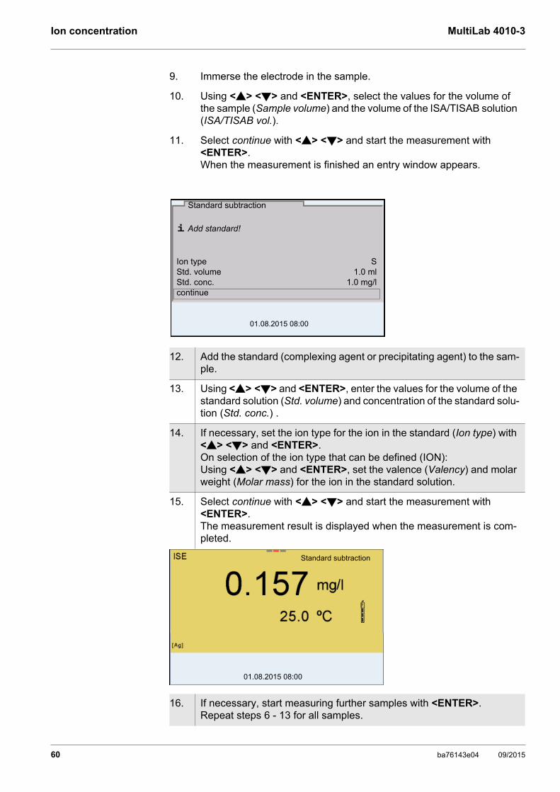
Ion concentration MultiLab 4010-3
9. Immerse the electrode in the sample.
10. Using <> <> and <ENTER>, select the values for the volume of the sample (Sample volume) and the volume of the ISA/TISAB solution (ISA/TISAB vol.).
11. Select continue with <> <> and start the measurement with <ENTER>.When the measurement is finished an entry window appears.
12. Add the standard (complexing agent or precipitating agent) to the sam-ple.
13. Using <> <> and <ENTER>, enter the values for the volume of the standard solution (Std. volume) and concentration of the standard solu-tion (Std. conc.) .
14. If necessary, set the ion type for the ion in the standard (Ion type) with <> <> and <ENTER>.On selection of the ion type that can be defined (ION):Using <> <> and <ENTER>, set the valence (Valency) and molar weight (Molar mass) for the ion in the standard solution.
15. Select continue with <> <> and start the measurement with <ENTER>.The measurement result is displayed when the measurement is com-pleted.
16. If necessary, start measuring further samples with <ENTER>.Repeat steps 6 - 13 for all samples.
i Add standard!
Ion type SStd. volume 1.0 mlStd. conc. 1.0 mg/lcontinue
Standard subtraction
01.08.2015 08:00
01.08.2015 08:00
Standard subtraction
60 ba76143e04 09/2015

MultiLab 4010-3 Ion concentration
17. Terminate the measuring method with <M>.A safety query appears.
18. Select yes with <> <>.
19. Confirm yes with <ENTER>.Measurement with the selected method is completed.
ba76143e04 09/2015 61

Ion concentration MultiLab 4010-3
7.3.3 Sample addition
In the "Sample addition" procedure, a known amount of sample is added to the standard solution.
The ion concentration in the sample is calculated from the change in potential.
Calibration
Measuring
1. Select the measuring method (see section 7.3 SELECTING THE MEASU-RING METHOD, page 56).
2. Prepare two standard calibration solutions.
3. Perform a two-point calibration according to user guidance.
4. The calibration record is displayed as soon as a stable value is achieved for the second standard calibration solution.
01.08.2015 08:00
01.08.2015 08:00
#1 0.010 mg/l 20.2 mV 25.0 °C#2 0.020 mg/l 79.2 mV 25.0 °CSlp.: 54.1 mVSensor +++ (Ion type: Ag)
CALIBRATIONADA 94/IDS BNCB092500013
5. Start the measurement with <F1>/[continue].An entry window appears.
6. Prepare the standard solution.
7. If necessary, add the ISA/TISAB solution to the standard solution.
8. Thoroughly rinse the electrode with deionized water.
9. Immerse the electrode in the standard.
i Immerse sensor in standard
Std. volume 100.0 mlStd. conc. 1.0 mg/lISA/TISAB vol. 1.0 mlcontinue
Sample addition
01.08.2015 08:00
62 ba76143e04 09/2015

MultiLab 4010-3 Ion concentration
10. Using <> <> and <ENTER>, enter the values for the volume of the standard solution (Std. volume), the concentration of the standard solu-tion (Std. conc.) and the volume of the ISA/TISAB solution (ISA/TISAB vol.).
11. Select continue with <> <> and start the measurement with <ENTER>.When the measurement is finished an entry window appears.
12. Add the sample to the standard solution.
13. Using <> <> and <ENTER>, enter the value for the volume of the sample (Sample volume).
14. Select continue with <> <> and start the measurement with <ENTER>.The measurement result is displayed when the measurement is com-pleted.
15. If necessary, start measuring further samples with <ENTER>.Repeat steps 6 - 12 for all samples.
16. Terminate the measuring method with <M>.A safety query appears.
17. Select yes with <> <>.
18. Confirm yes with <ENTER>.Measurement with the selected method is completed.
i Add sample!
Sample volume 1.0 mlcontinue
Sample addition
01.08.2015 08:00
01.08.2015 08:00
Sample addition
ba76143e04 09/2015 63
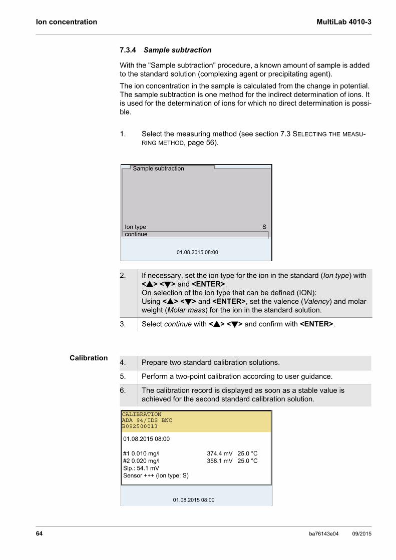
Ion concentration MultiLab 4010-3
7.3.4 Sample subtraction
With the "Sample subtraction" procedure, a known amount of sample is added to the standard solution (complexing agent or precipitating agent).
The ion concentration in the sample is calculated from the change in potential. The sample subtraction is one method for the indirect determination of ions. It is used for the determination of ions for which no direct determination is possi-ble.
Calibration
1. Select the measuring method (see section 7.3 SELECTING THE MEASU-RING METHOD, page 56).
2. If necessary, set the ion type for the ion in the standard (Ion type) with <> <> and <ENTER>.On selection of the ion type that can be defined (ION):Using <> <> and <ENTER>, set the valence (Valency) and molar weight (Molar mass) for the ion in the standard solution.
3. Select continue with <> <> and confirm with <ENTER>.
Ion type Scontinue
Sample subtraction
01.08.2015 08:00
4. Prepare two standard calibration solutions.
5. Perform a two-point calibration according to user guidance.
6. The calibration record is displayed as soon as a stable value is achieved for the second standard calibration solution.
01.08.2015 08:00
01.08.2015 08:00
#1 0.010 mg/l 374.4 mV 25.0 °C#2 0.020 mg/l 358.1 mV 25.0 °CSlp.: 54.1 mVSensor +++ (Ion type: S)
CALIBRATIONADA 94/IDS BNCB092500013
64 ba76143e04 09/2015
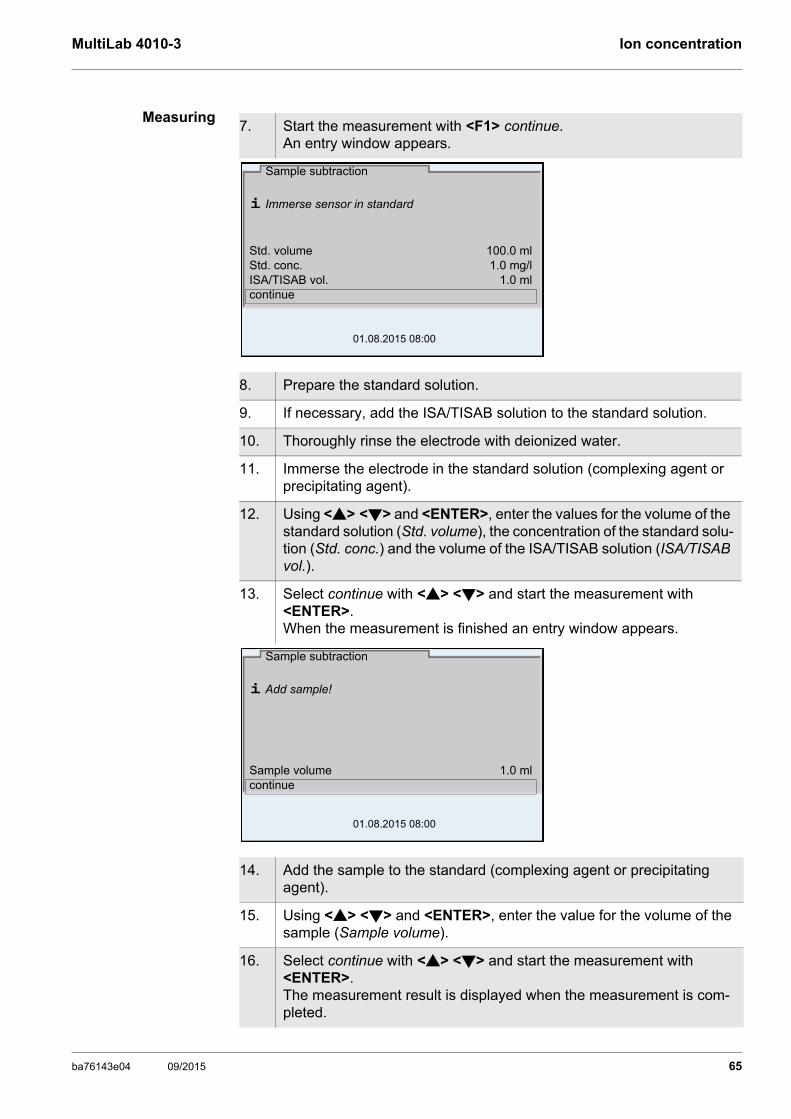
MultiLab 4010-3 Ion concentration
Measuring7. Start the measurement with <F1> continue.
An entry window appears.
8. Prepare the standard solution.
9. If necessary, add the ISA/TISAB solution to the standard solution.
10. Thoroughly rinse the electrode with deionized water.
11. Immerse the electrode in the standard solution (complexing agent or precipitating agent).
12. Using <> <> and <ENTER>, enter the values for the volume of the standard solution (Std. volume), the concentration of the standard solu-tion (Std. conc.) and the volume of the ISA/TISAB solution (ISA/TISAB vol.).
13. Select continue with <> <> and start the measurement with <ENTER>.When the measurement is finished an entry window appears.
14. Add the sample to the standard (complexing agent or precipitating agent).
15. Using <> <> and <ENTER>, enter the value for the volume of the sample (Sample volume).
16. Select continue with <> <> and start the measurement with <ENTER>.The measurement result is displayed when the measurement is com-pleted.
i Immerse sensor in standard
Std. volume 100.0 mlStd. conc. 1.0 mg/lISA/TISAB vol. 1.0 mlcontinue
Sample subtraction
01.08.2015 08:00
i Add sample!
Sample volume 1.0 mlcontinue
Sample subtraction
01.08.2015 08:00
ba76143e04 09/2015 65

Ion concentration MultiLab 4010-3
7.3.5 Standard addition with blank value correction (Blank value addition)
In the "Standard addition with blank value correction" procedure, a known amount of standard solution is added to the sample in two steps.
With the first addition, the ion concentration is raised to the linear range of the electrode characteristic curve.
The second addition is equivalent to the standard addition. The ion concentra-tion in the sample is calculated from the change in potential.
Calibration
17. If necessary, start measuring further samples with <ENTER>.Repeat steps 8 - 16 for all samples.
18. Terminate the measuring method with <M>.A safety query appears.
19. Select yes with <> <>.
20. Confirm yes with <ENTER>.Measurement with the selected method is completed.
1. Select the measuring method (see section 7.3 SELECTING THE MEASU-RING METHOD, page 56).
01.08.2015 08:00
Sample subtraction
2. Prepare two standard calibration solutions.
3. Perform a two-point calibration according to user guidance.
4. The calibration record is displayed as soon as a stable value is achieved for the second standard calibration solution.
66 ba76143e04 09/2015
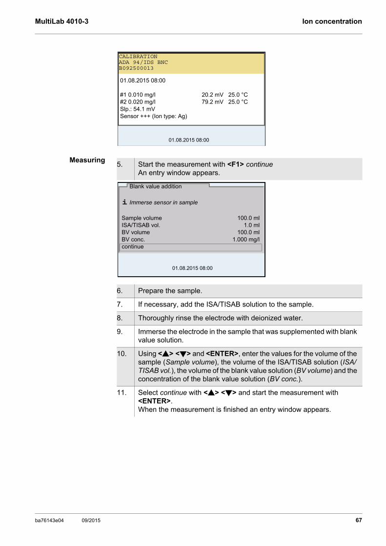
MultiLab 4010-3 Ion concentration
Measuring
01.08.2015 08:00
01.08.2015 08:00
#1 0.010 mg/l 20.2 mV 25.0 °C#2 0.020 mg/l 79.2 mV 25.0 °CSlp.: 54.1 mVSensor +++ (Ion type: Ag)
CALIBRATIONADA 94/IDS BNCB092500013
5. Start the measurement with <F1> continueAn entry window appears.
6. Prepare the sample.
7. If necessary, add the ISA/TISAB solution to the sample.
8. Thoroughly rinse the electrode with deionized water.
9. Immerse the electrode in the sample that was supplemented with blank value solution.
10. Using <> <> and <ENTER>, enter the values for the volume of the sample (Sample volume), the volume of the ISA/TISAB solution (ISA/TISAB vol.), the volume of the blank value solution (BV volume) and the concentration of the blank value solution (BV conc.).
11. Select continue with <> <> and start the measurement with <ENTER>.When the measurement is finished an entry window appears.
i Immerse sensor in sample
Sample volume 100.0 mlISA/TISAB vol. 1.0 mlBV volume 100.0 mlBV conc. 1.000 mg/lcontinue
Blank value addition
01.08.2015 08:00
ba76143e04 09/2015 67
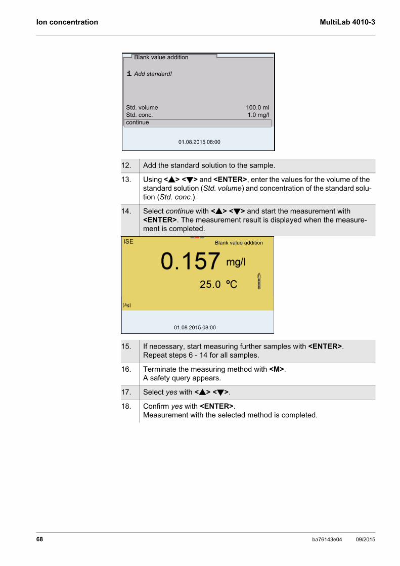
Ion concentration MultiLab 4010-3
12. Add the standard solution to the sample.
13. Using <> <> and <ENTER>, enter the values for the volume of the standard solution (Std. volume) and concentration of the standard solu-tion (Std. conc.).
14. Select continue with <> <> and start the measurement with <ENTER>. The measurement result is displayed when the measure-ment is completed.
15. If necessary, start measuring further samples with <ENTER>.Repeat steps 6 - 14 for all samples.
16. Terminate the measuring method with <M>.A safety query appears.
17. Select yes with <> <>.
18. Confirm yes with <ENTER>.Measurement with the selected method is completed.
i Add standard!
Std. volume 100.0 mlStd. conc. 1.0 mg/lcontinue
Blank value addition
01.08.2015 08:00
01.08.2015 08:00
Blank value addition
68 ba76143e04 09/2015

MultiLab 4010-3 Dissolved oxygen (D.O.)
8 Dissolved oxygen (D.O.)
8.1 Measuring
8.1.1 Measuring D.O.
Selecting thedisplayed
measured parameter
You can switch between the following displays with <M>:
D.O. concentration [mg/l]
D.O. saturation [%]
Salinity correction When measuring the D.O. concentration of solutions with a salt content of more than 1 psu, a salinity correction is required. For this, you have to measure and input the salinity of the measured medium first.
When the salinity correction is switched on, the [Sal] indicator is displayed in the measuring screen.
Air pressurecorrection
(Saturation localfunction)
The integrated air pressure sensor of the MultiLab 4010-3 measures the current air pressure.During calibration, the air pressure correction function is automatically activated. For measurement, the air pressure correction is applied if the parameter oxygen saturation [%] is displayed and the Saturation local function is enabled.
The current air pressure is displayed, when an IDS D.O. sensor is connected.
1. Connect the IDS D.O. sensor to the meter. The D.O. measuring screen is displayed.
2. If necessary, select the measured parameter with <M>.
3. Check or calibrate the meter with the sensor.
4. Immerse the D.O. sensor in the test sample.
01.08.2013 08:00Info
760 mmHg 25.1 °C
You can switch the salinity correction on or off and enter the salinity in the menu for calibration and measurement settings (see section 10.4.1 SETTINGS FOR D.O. MEASUREMENT, page 91).
ba76143e04 09/2015 69

Dissolved oxygen (D.O.) MultiLab 4010-3
Stability control(AutoRead)
& HOLD function
The stability control function (AutoRead) continually checks the stability of the measurement signal. The stability has a considerable impact on the reproduc-ibility of measured values.
The measured parameter flashes on the display
as soon as the measured value is outside the stability range
when the automatic Stability control is switched off.
Irrespective of the setting for automatic Stability control (see section 10.6.3 AUTOMATIC STABILITY CONTROL, page 96) in the System menu, you can start a measurement with Stability control manually at any time.
Criteria for a stablemeasured value
The Stability control function checks whether the measured values are stable
The Saturation local function for the parameter oxygen saturation [%] is switched on or off in the menu for calibration and measure-ment settings (see section 10.4.3 SATURATION LOCAL, page 91).
1. Freeze the measured value with <AR>.The [HOLD] status indicator is displayed. The HOLD function is active.
You can terminate the Stability control function and the HOLD func-tion with <AR> or <M> at any time.
2. Using <ENTER>, activate the Stability control function manually.The [AR] status indicator appears while the measured value is assessed as not stable. A progress bar is displayed and the display of the measured parameter flashes.As soon as a measured value meets the stability criteria, it is frozen. The [HOLD][AR] status indicator is displayed, the progress bar disappears and the display of the measured parameter stops flashing. The current measurement data is output to the interface. Measurement data meeting the stability control criterion is marked by AR.
You can prematurely terminate the Stability control function manu-ally with <ENTER> at any time. When the Stability control function is prematurely terminated, the current measurement data are out-put to the interface (PC, USB memory device or USB printer) with-out AutoRead info.
3. Using <ENTER>, start a further measurement with stability control.orRelease the frozen measured value again with <AR> or <M>.The [AR] status display disappears. The display switches back to the previous indication.
70 ba76143e04 09/2015

MultiLab 4010-3 Dissolved oxygen (D.O.)
within the monitored time interval.
The minimum duration until a measured value is assessed as stable is the mon-itored time interval. The actual duration is mostly longer.
8.1.2 Measuring the temperature
For reproducible D.O. measurements, it is essential to measure the tempera-ture of the test sample.
IDS D.O. sensors measure the temperature with a temperature sensor inte-grated in the IDS sensor.
8.2 Calibration
8.2.1 Why calibrate?
D.O. sensors age. This changes the zero point (asymmetry) and slope of the D.O. sensor. As a result, an inexact measured value is displayed. Calibration determines and stores the current values of the zero point and slope.
8.2.2 When to calibrate?
When the calibration interval has expired
When your accuracy requirements are especially high
Routinely within the framework of the company quality assurance
8.2.3 Calibration procedures
The MultiLab 4010-3 provides 2 calibration procedures:
Calibration in water vapor-saturated air.
Calibration via a comparison measurement (e.g. Winkler titration according to DIN EN 25813 or ISO 5813). At the same time, the relative slope is adapted to the comparison measurement by a correction factor. When the correction factor is active, the [Factor] indicator appears in the measuring window.
Calibration can be carried out either as a 1-point calibration or 2-point calibra-tion procedure.
Measured parameter Time interval Stability in the time interval
D.O. concentration 20 seconds ∆ : better than 0.03 mg/l
D.O. saturation 20 seconds ∆ : better than 0.4 %
Temperature 15 seconds ∆ : Better than 0.5 °C
ba76143e04 09/2015 71
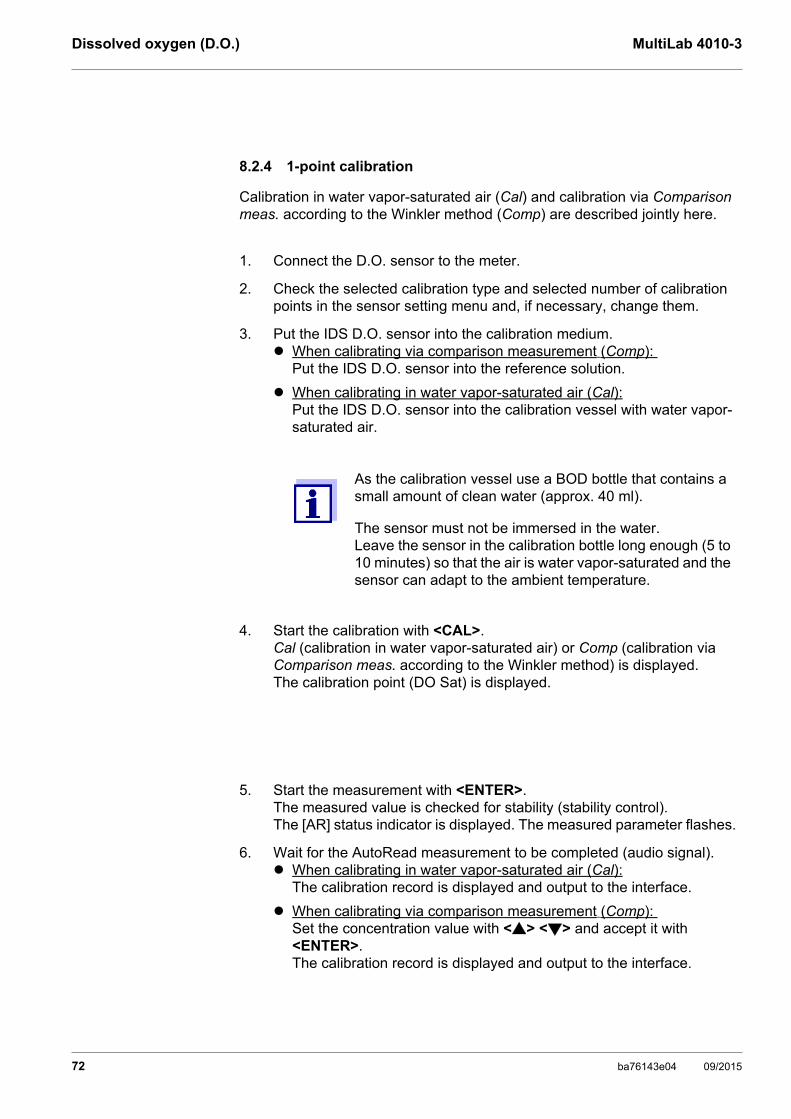
Dissolved oxygen (D.O.) MultiLab 4010-3
8.2.4 1-point calibration
Calibration in water vapor-saturated air (Cal) and calibration via Comparison meas. according to the Winkler method (Comp) are described jointly here.
1. Connect the D.O. sensor to the meter.
2. Check the selected calibration type and selected number of calibration points in the sensor setting menu and, if necessary, change them.
3. Put the IDS D.O. sensor into the calibration medium. When calibrating via comparison measurement (Comp):
Put the IDS D.O. sensor into the reference solution.
When calibrating in water vapor-saturated air (Cal):Put the IDS D.O. sensor into the calibration vessel with water vapor-saturated air.
As the calibration vessel use a BOD bottle that contains a small amount of clean water (approx. 40 ml).
The sensor must not be immersed in the water.Leave the sensor in the calibration bottle long enough (5 to 10 minutes) so that the air is water vapor-saturated and the sensor can adapt to the ambient temperature.
4. Start the calibration with <CAL>.Cal (calibration in water vapor-saturated air) or Comp (calibration via Comparison meas. according to the Winkler method) is displayed.The calibration point (DO Sat) is displayed.
5. Start the measurement with <ENTER>.The measured value is checked for stability (stability control).The [AR] status indicator is displayed. The measured parameter flashes.
6. Wait for the AutoRead measurement to be completed (audio signal). When calibrating in water vapor-saturated air (Cal):
The calibration record is displayed and output to the interface.
When calibrating via comparison measurement (Comp): Set the concentration value with <> <> and accept it with <ENTER>.The calibration record is displayed and output to the interface.
72 ba76143e04 09/2015

MultiLab 4010-3 Dissolved oxygen (D.O.)
8.2.5 2-point calibration
Calibration in water vapor-saturated air (Cal) and calibration via Comparison meas. according to the Winkler method (Comp) are described jointly here.
7. Switch to the measured value display with <ENTER>.
1. Connect the D.O. sensor to the meter.
2. Check the selected calibration type and selected number of calibration points in the sensor setting menu and, if necessary, change them.
3. Place the D.O. sensor in a solution that does not contain any dissolved oxygen.
A solution not containing any dissolved oxygen can be prepared by dissolving approx. 8 to 10 g sodium sulfite (Na2SO3) in 500 ml tap-water. Carefully mix the solution. It may take up to 60 minutes until the solution is free of oxygen.
4. Start the calibration with <CAL>.Cal (calibration in water vapor-saturated air) or Comp (calibration via Comparison meas. according to the Winkler method) is displayed.The calibration point 1 (0%) is displayed.
5. Start the measurement with <ENTER>.The measured value is checked for stability (stability control).The [AR] status indicator is displayed. The measured parameter flashes.
6. Wait for the AutoRead measurement to be completed (audio signal).The display for the second calibration point is displayed.
7. Put the IDS D.O. sensor into the calibration medium. When calibrating via comparison measurement (Comp):
Put the IDS D.O. sensor into the reference solution..
When calibrating in water vapor-saturated air (Cal):Put the IDS D.O. sensor into the calibration vessel with water vapor-saturated air.
ba76143e04 09/2015 73

Dissolved oxygen (D.O.) MultiLab 4010-3
8.2.6 Calibration data
Displaying thecalibration record
The calibration record of the last calibration is to be found under the menu item, Calibration / Calibration record. To open it in the measured value display, press the <CAL_> key.
The calibration records of the last 10 calibrations are to be found in the menu, Calibration / Calibration data storage / Display. To open the Calibration menu, press the <ENTER> key in the measured value display.
As the calibration vessel use a BOD bottle that contains a small amount of clean water (approx. 40 ml).
The sensor must not be immersed in the water.Leave the sensor in the calibration bottle long enough (5 to 10 minutes) so that the air is water vapor-saturated and the sensor can adapt to the ambient temperature.
8. Start the measurement with <ENTER>.The measured value is checked for stability (stability control).The [AR] status indicator is displayed. The measured parameter flashes.
9. Wait for the AutoRead measurement to be completed (audio signal). When calibrating in water vapor-saturated air (Cal):
The calibration record is displayed and output to the interface.
When calibrating via comparison measurement (Comp): Set the concentration value with <> <> and accept it with <ENTER>.The calibration record is displayed and output to the interface.
10. Switch to the measured value display with <ENTER>.
The calibration record is automatically transmitted to the interface after calibrating.
74 ba76143e04 09/2015

MultiLab 4010-3 Dissolved oxygen (D.O.)
Calibrationevaluation
After calibration, the meter automatically evaluates the current status of the calibration. The evaluation appears on the display and in the calibration record.
ProOBODcalibrationevaluation
Menu item Setting/func-tion
Explanation
Calibration / Calibration data storage /Display
- Displays the calibration records.Further options: Scroll through the calibration
records with <><>.
Using <PRT>, output the dis-played calibration record to the USB-B (PC) interface or the USB-A (USB printer) interface .
Using <PRT_>, output all cal-ibration records to the USB-B (PC) interface or the USB-A (USB printer) interface .
Quit the display with <ESC>.
Switch directly to the mea-sured value display with <M>.
Calibration / Cali-bration data stor-age / Output to USB flash drive or printer
- Outputs the stored calibration data to the USB-A interface (USB memory device/USB printer)
Calibration / Calibration data storage / Output to RS232/USB
- Outputs the stored calibration data to the USB-B interface (PC)
Display Calibration record Relative slope
+++ S = 0.94 ... 1.06
++ S = 0.92 ... 0.94 orS = 1.06 ... 1.08
+ S = 0.90 ... 0.92 orS = 1.08 ... 1.10
Error Error S < 0.90 or S > 1.10Error elimination (see section 14 WHAT TO DO IF...,
page 114)
ba76143e04 09/2015 75
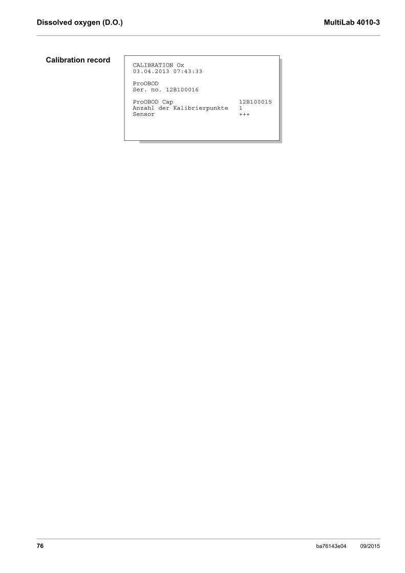
Dissolved oxygen (D.O.) MultiLab 4010-3
Calibration recordCALIBRATION Ox03.04.2013 07:43:33
ProOBODSer. no. 12B100016
ProOBOD Cap 12B100015Anzahl der Kalibrierpunkte 1Sensor +++
76 ba76143e04 09/2015

MultiLab 4010-3 Conductivity
9 Conductivity
9.1 Measuring
9.1.1 Measuring the conductivity
Selecting thedisplayed
measured parameter
You can switch between the following displays with <M>:
Conductivity [μS/cm] / [mS/cm]
Resistivity [Ω·cm] / [kΩ·cm] / [MΩ·cm]
Salinity SaL [ ] ( ≙ psu)
Total dissolved solids TDS [mg/l] / [g/l]
The factor to calculate the total dissolved solids is set to 1.00 in the factory. You can adjust this factor to meet your requirements in the range 0.40 ... 1.00. The factor is set in the menu for the parameter TDS.
Stability control(AutoRead)
& HOLD function
The stability control function (AutoRead) continually checks the stability of the measurement signal. The stability has a considerable impact on the reproduc-ibility of measured values.
The measured parameter flashes on the display
as soon as the measured value is outside the stability range
when the automatic Stability control is switched off.
The sensor connection and the USB-B (device) interface are gal-vanically isolated. This facilitates interference-free measurements also in the following cases:
Measurement in grounded test samples
Measurement with several sensors connected to one MultiLab 4010-3 in one test sample
1. Connect the conductivity sensor to the meter. The conductivity measuring window is displayed.The measuring cell and cell constant for the connected IDS conductivity sensor are automatically taken over.
2. If necessary, press <M> to select the measured parameter ϰ.
3. Immerse the conductivity sensor in the test sample.
01.08.2013 08:00Info
ba76143e04 09/2015 77

Conductivity MultiLab 4010-3
You can start the Stability control manually at any time, irrespective of the set-ting for automatic Stability control (see section 10.6.3 AUTOMATIC STABILITY CONTROL, page 96) in the System menu.
Criteria for a stablemeasured value
The Stability control function checks whether the measured values are stable within the monitored time interval.
The minimum duration until a measured value is assessed as stable is the mon-itored time interval. The actual duration is mostly longer.
1. Freeze the measured value with <AR>.The [HOLD] status indicator is displayed. The HOLD function is active.
You can terminate the Stability control function and the HOLD func-tion with <AR> or <M> at any time.
2. Using <ENTER>, activate the Stability control function manually.The [AR] status indicator appears while the measured value is assessed as not stable. A progress bar is displayed and the display of the measured parameter flashes.As soon as a measured value meets the stability criteria, it is frozen. The [HOLD][AR] status indicator is displayed, the progress bar disappears and the display of the measured parameter stops flashing. The current measurement data is output to the interface. Measurement data meeting the stability control criterion is marked by AR.
You can prematurely terminate the Stability control function manu-ally with <ENTER> at any time. When the Stability control function is prematurely terminated, the current measurement data are out-put to the interface (PC, USB memory device or USB printer) with-out AutoRead info.
3. Using <ENTER>, start a further measurement with stability control.orRelease the frozen measured value again with <AR> or <M>.The [AR] status display disappears. The display switches back to the previous indication.
Measured parameter
Time interval Stability in the time interval
Conductivity ϰ 10 seconds ∆ ϰ: better than 1.0% of measured value
Temperature 15 seconds ∆ : Better than 0.5 °C
78 ba76143e04 09/2015

MultiLab 4010-3 Conductivity
9.1.2 Measuring the temperature
For reproducible conductivity measurements, it is essential to measure the temperature of the test sample.
IDS sensors measure the temperature with a temperature sensor integrated in the IDS sensor.
9.2 Temperature compensation
The calculation of the temperature compensation is based on the preset refer-ence temperature, 20 °C or 25 °C. It appears on the display as Tr20 or Tr25.
You can select one of the following temperature compensation methods:
Nonlinear temperature compensation (nLF) according to ISO 7888
Linear temperature compensation (lin) with adjustable coefficients of 0.000 ... 3.000 %/K
No temperature compensation (off)
Application tips Select the following temperature compensations given in the table according to the respective test sample:
The reference temperature and temperature compensation are set in the menu for the parameter, conductivity (see section 10.5.1 SET-TINGS FOR IDS CONDUCTIVITY SENSORS, page 91).
Test sample Temperature compensation Display
Natural water (ground water, surface water, drinking water)
nLF according to ISO 7888
nLF
Ultrapure water nLF according to ISO 7888
nLF
Other aqueous solu-tions
lin Set linear temperature coefficient0.000 ... 10.000 %/K
lin
Salinity (seawater) Automatic nLF according to IOT (International Oceano-graphic Tables)
Sal, nLF
ba76143e04 09/2015 79
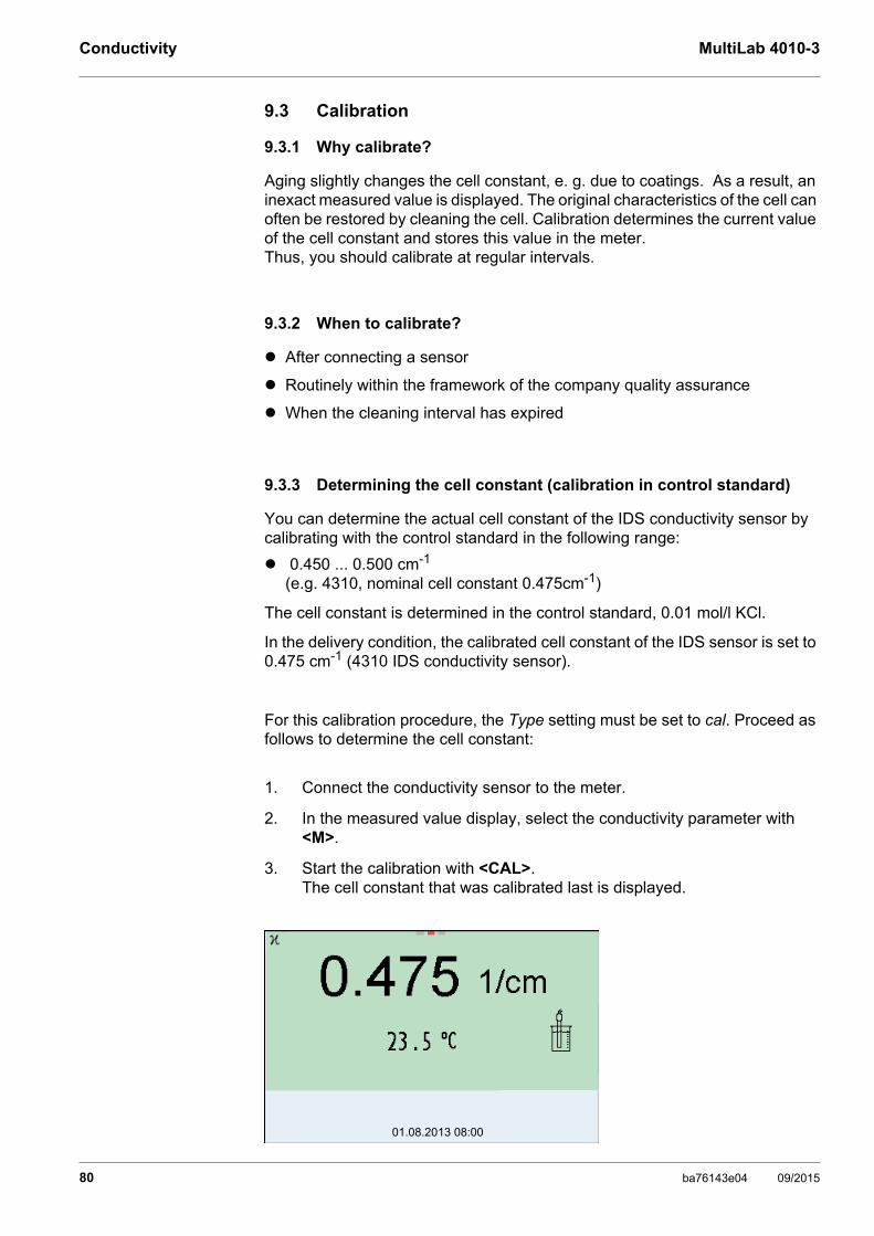
Conductivity MultiLab 4010-3
9.3 Calibration
9.3.1 Why calibrate?
Aging slightly changes the cell constant, e. g. due to coatings. As a result, an inexact measured value is displayed. The original characteristics of the cell can often be restored by cleaning the cell. Calibration determines the current value of the cell constant and stores this value in the meter.Thus, you should calibrate at regular intervals.
9.3.2 When to calibrate?
After connecting a sensor
Routinely within the framework of the company quality assurance
When the cleaning interval has expired
9.3.3 Determining the cell constant (calibration in control standard)
You can determine the actual cell constant of the IDS conductivity sensor by calibrating with the control standard in the following range:
0.450 ... 0.500 cm-1 (e.g. 4310, nominal cell constant 0.475cm-1)
The cell constant is determined in the control standard, 0.01 mol/l KCl.
In the delivery condition, the calibrated cell constant of the IDS sensor is set to 0.475 cm-1 (4310 IDS conductivity sensor).
For this calibration procedure, the Type setting must be set to cal. Proceed as follows to determine the cell constant:
1. Connect the conductivity sensor to the meter.
2. In the measured value display, select the conductivity parameter with <M>.
3. Start the calibration with <CAL>.The cell constant that was calibrated last is displayed.
01.08.2013 08:00
80 ba76143e04 09/2015
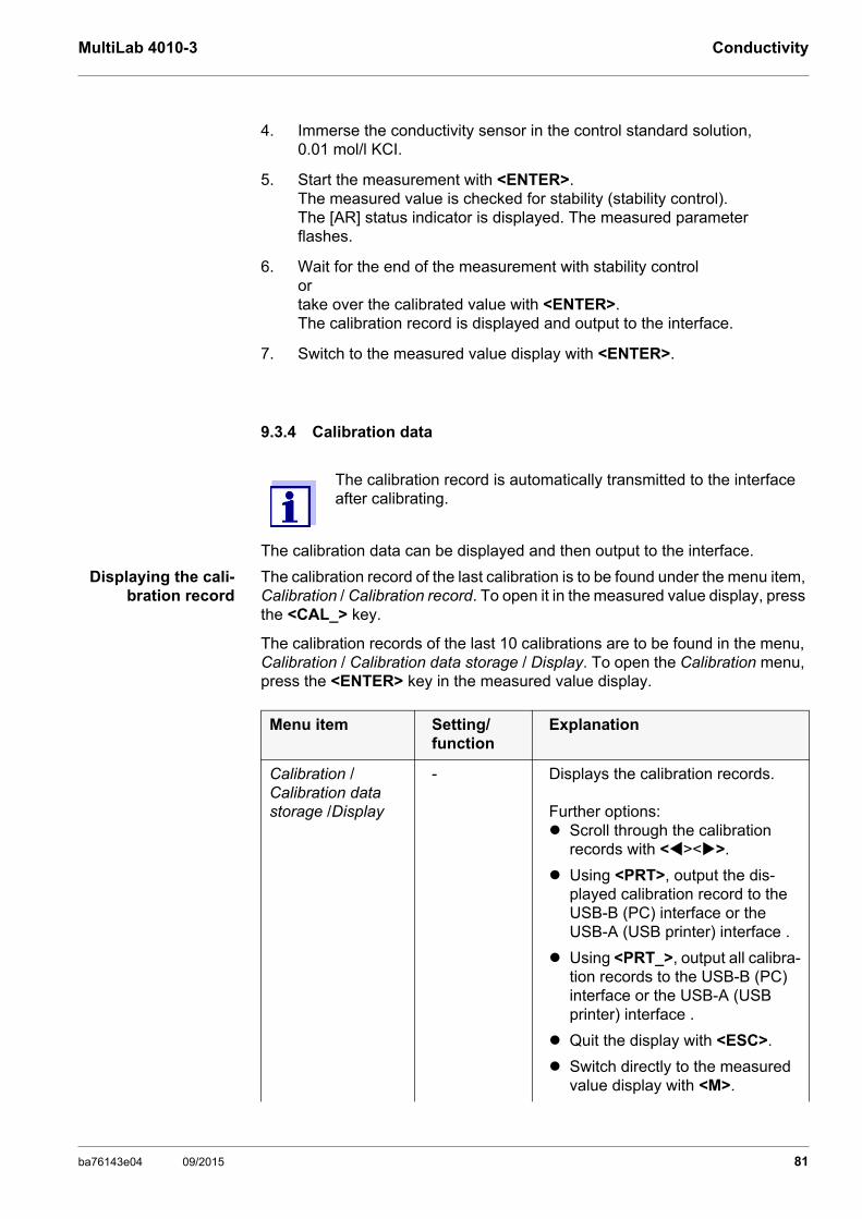
MultiLab 4010-3 Conductivity
9.3.4 Calibration data
The calibration data can be displayed and then output to the interface.
Displaying the cali-bration record
The calibration record of the last calibration is to be found under the menu item, Calibration / Calibration record. To open it in the measured value display, press the <CAL_> key.
The calibration records of the last 10 calibrations are to be found in the menu, Calibration / Calibration data storage / Display. To open the Calibration menu, press the <ENTER> key in the measured value display.
4. Immerse the conductivity sensor in the control standard solution, 0.01 mol/l KCI.
5. Start the measurement with <ENTER>.The measured value is checked for stability (stability control).The [AR] status indicator is displayed. The measured parameter flashes.
6. Wait for the end of the measurement with stability control or take over the calibrated value with <ENTER>.The calibration record is displayed and output to the interface.
7. Switch to the measured value display with <ENTER>.
The calibration record is automatically transmitted to the interface after calibrating.
Menu item Setting/function
Explanation
Calibration / Calibration data storage /Display
- Displays the calibration records.
Further options: Scroll through the calibration
records with <><>.
Using <PRT>, output the dis-played calibration record to the USB-B (PC) interface or the USB-A (USB printer) interface .
Using <PRT_>, output all calibra-tion records to the USB-B (PC) interface or the USB-A (USB printer) interface .
Quit the display with <ESC>.
Switch directly to the measured value display with <M>.
ba76143e04 09/2015 81
Conductivity MultiLab 4010-3
Calibrationevaluation
After calibration, the meter automatically evaluates the current status of the cal-ibration. The evaluation appears on the display and in the calibration record.
Calibration record
Calibration / Cali-bration data stor-age / Output to USB flash drive or printer
- Outputs the stored calibration data to the USB-A interface (USB mem-ory device/USB printer)
Calibration / Calibration data storage / Output to RS232/USB
- Outputs the stored calibration data to the USB-B interface (PC)
Menu item Setting/function
Explanation
Display Calibration record Cell constant [cm-1]
+++ Within the range0.450 ... 0.500 cm-1
Error Error Outside the range0.450 ... 0.500 cm-1
Error elimination (see section 14 WHAT TO DO IF..., page 114)
CALIBRATION Cond03.04.2013 07:43:33
4310Ser. no. 09250033
Cell constant 0.476 1/cm 25.0 °CSensor +++
82 ba76143e04 09/2015

MultiLab 4010-3 Settings
10 Settings
10.1 pH measurement settings
10.1.1 Settings for pH measurements
The settings are made in the menu for calibration and measurement settings of the pH/ORP measurement. To open the settings, display the required mea-sured parameter in the measured value display and press the <ENTER> key. After completing the settings, switch to the measured value display with <M>.Default settings are printed in bold.
Menu item Possible setting
Explanation
Calibration /Calibration record
- Displays the calibration record of the last calibration.
Calibration / Calibration data storage / Display
- Displays the last calibration records (max. 10)
Calibration / Calibration data storage / Output to RS232/USB
- Outputs the stored calibration data to the USB-B interface (PC)
Calibration / Calibration data storage / Output to USB flash drive or printer
- Outputs the stored calibration data to the USB-A interface (USB memory device/USB printer)
Calibration /Buffer YSIConCalNIST/DIN ...
Buffer sets to be used for pH calibration.More buffers and details: see section 10.1.2 BUFFER SETS FOR CALIBRATION, page 85 and section 5.2 PH CALIBRATION, page 29.
Calibration /Single-point calibration
yesno
Quick calibration with 1 buffer
Calibration /Calibration interval
1 ... 7 ... 999 d
Calibration interval for the IDS pH sensor (in days).The meter reminds you to calibrate regularly by the flash-ing sensor symbol in the measuring screen.
Calibration /Unit for slope
mV/pH%
Unit of the slope.The % display refers to the Nernst slope of -59.2 mV/pH (100 x determined slope/Nernst slope).
QSC /First calibration - Starts the initial calibration with QSC buffers.This menu item is only available as long as no initial cali-bration was carried out with the connected IDS sensor.
QSC /Record of first cal-ibration
- Displays the calibration record of the QSC initial calibra-tion.
QSC /Control calibra-tion
- Starts the control calibration with QSC buffers.This menu item is only available if an initial calibration was carried out with the connected IDS sensor.
ba76143e04 09/2015 83

Settings MultiLab 4010-3
Alternative temperature onoff
Takes the measured temperature value from an IDS sen-sor.This menu item is only available if an IDS adapter and an IDS sensor with temperature sensor are connected.
Temperature from channel
▭▭▬▭▬▭▬▭▭
Selection of the channel from which the temperature value should be taken over.This menu item is only available if two IDS sensors are additionally connected.
Man. temperature -25 ... +25 ... +130 °C
Entry of the manually determined temperature.This menu item is only available if an IDS adapter is con-nected.
pH resolution 0.0010.010.1
Resolution of the pH display
mV resolution 0.11
Resolution of the mV display
Limit monitoring With the Limit monitoring function you define the mea-sured values whose exceeding is signaled. An acoustic signal sounds, and at the same time a message is output to the USB interface.You can switch on or off the acoustic signal in the System menu (see section 10.6.1 SYSTEM, page 95).
Limit monitoring/pH monitoring
onoff
Switch on or off the limit signaling device for the pH value.
Limit monitoring/TP monitoring
onoff
Switch on or off the limit signaling device for the tempera-ture value.
Limit monitoring/pH monitoring/on/pH upper limit
-2 ... 20 Upper limit. A message is output to the USB interface if it is exceeded.This menu item is only visible when the pH monitoring set-ting is active.
Limit monitoring/pH monitoring/on/pH lower limit
-2 ... 20 Lower limit. A message is output to the USB interface if it is exceeded.This menu item is only visible when the pH monitoring set-ting is active.
Limit monitoring/TP monitoring/on/TP upper limit
-5 ... +105 °C
Upper limit. A message is output to the USB interface if it is exceeded.This menu item is only visible when the TP monitoring set-ting is active.
Limit monitoring/TP monitoring/on/TP lower limit
-5 ... 105 °C Lower limit. A message is output to the USB interface if it is exceeded.This menu item is only visible when the TP monitoring set-ting is active.
Menu item Possible setting
Explanation
84 ba76143e04 09/2015

MultiLab 4010-3 Settings
10.1.2 Buffer sets for calibration
You can use the buffer sets quoted in the table for an automatic calibration. The pH values are valid for the specified temperature values. The temperature dependence of the pH values is taken into consideration during the calibration.
Reset - Resets all sensor settings to the delivery condition (see section 10.7.1 RESETTING THE MEASUREMENT SETTINGS, page 97).
Menu item Possible setting
Explanation
No. Buffer set * pH values at
1 YSI * 4.0007.00010.000
25 °C
2 ConCal Any Any
3 NIST/DINDIN buffers according to DIN 19266 and NIST Traceable Buffers
1.6794.0066.8659.18012.454
25 °C
4 TECTechnical buffers
2.0004.0107.00010.011
25 °C
5 Merck 1* 4.0007.0009.000
20 °C
6 Merck 2 * 1.0006.0008.00013.000
20 °C
7 Merck 3 * 4.6606.8809.220
20 °C
8 Merck 4 * 2.0004.0007.00010.000
20 °C
9 Merck 5 * 4.0107.00010.000
25 °C
ba76143e04 09/2015 85
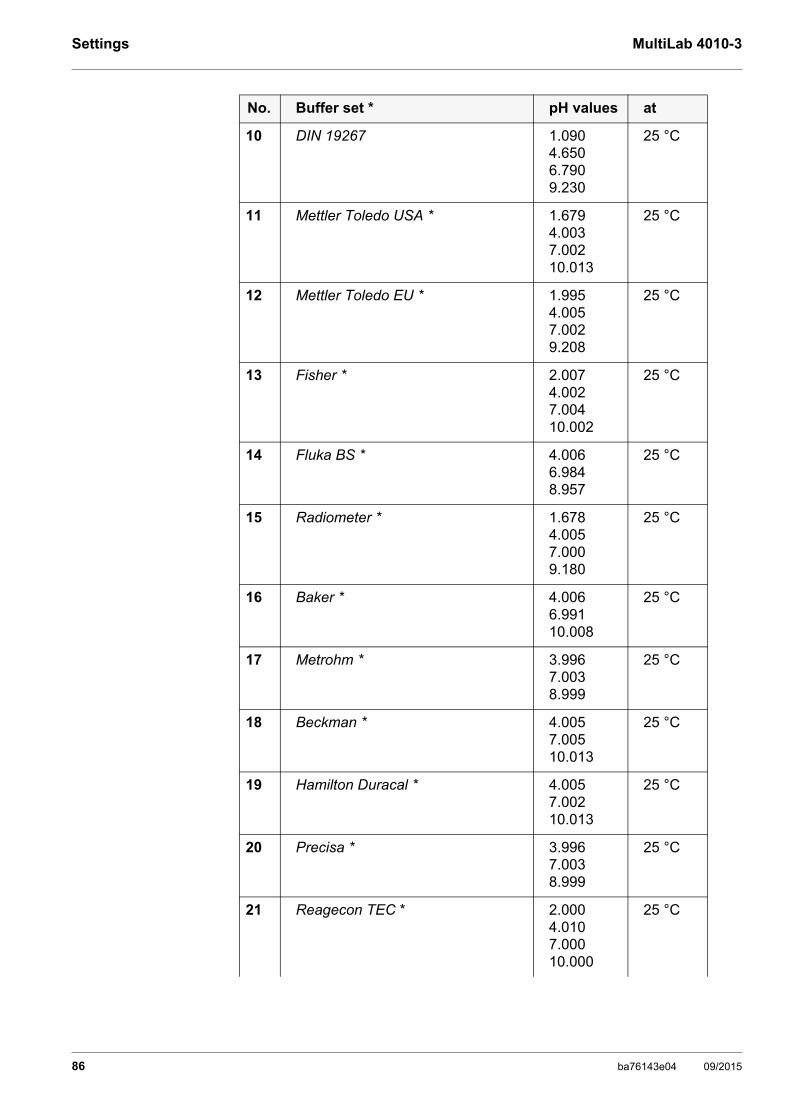
Settings MultiLab 4010-3
10 DIN 19267 1.0904.6506.7909.230
25 °C
11 Mettler Toledo USA * 1.6794.0037.00210.013
25 °C
12 Mettler Toledo EU * 1.9954.0057.0029.208
25 °C
13 Fisher * 2.0074.0027.00410.002
25 °C
14 Fluka BS * 4.0066.9848.957
25 °C
15 Radiometer * 1.6784.0057.0009.180
25 °C
16 Baker * 4.0066.99110.008
25 °C
17 Metrohm * 3.9967.0038.999
25 °C
18 Beckman * 4.0057.00510.013
25 °C
19 Hamilton Duracal * 4.0057.00210.013
25 °C
20 Precisa * 3.9967.0038.999
25 °C
21 Reagecon TEC * 2.0004.0107.00010.000
25 °C
No. Buffer set * pH values at
86 ba76143e04 09/2015

MultiLab 4010-3 Settings
* Brand names or trade names are trademarks of their respective owners protected by law.
10.1.3 Calibration interval
The calibration evaluation is displayed as a sensor symbol.
After the QSC function has been enabled the sensor symbol is replaced by the QSC scale (see section 5.2.8 QSC FUNCTION (SENSOR QUALITY CONTROL), page 40).
After the specified calibration interval has expired the sensor symbol or the QSC scale flashes. It is still possible to measure.
Setting the calibra-tion interval
The calibration interval is set to 7 days in the factory. You can change the interval (1 ... 999 days):
22 Reagecon 20 * 2.0004.0007.00010.00013.000
20 °C
23 Reagecon 25 * 2.0004.0007.00010.00013.000
25 °C
24 Chemsolute * 2.0004.0007.00010.000
20 °C
25 USABlueBook * 4.0007.00010.000
25 °C
The buffers are selected in the menu, pH / <ENTER> / Calibration / Buffer (see section 10.1.1 SETTINGS FOR PH MEASUREMENTS, page 83).
To ensure the high measuring accuracy of the measuring system, calibrate after the calibration interval has expired.
No. Buffer set * pH values at
1. Open the menu for measurement settings with <ENTER>.
2. In the Calibration / Calibration interval menu, set the calibration interval with <><>.
ba76143e04 09/2015 87
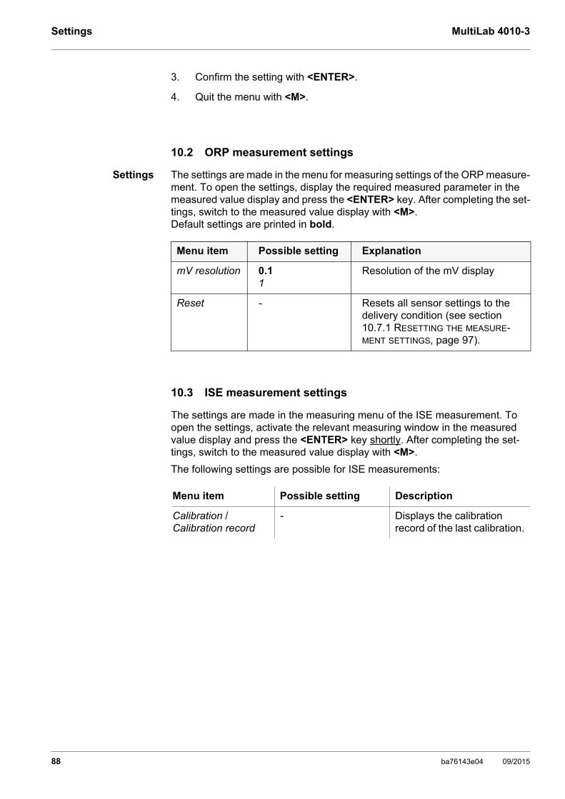
Settings MultiLab 4010-3
10.2 ORP measurement settings
Settings The settings are made in the menu for measuring settings of the ORP measure-ment. To open the settings, display the required measured parameter in the measured value display and press the <ENTER> key. After completing the set-tings, switch to the measured value display with <M>.Default settings are printed in bold.
10.3 ISE measurement settings
The settings are made in the measuring menu of the ISE measurement. To open the settings, activate the relevant measuring window in the measured value display and press the <ENTER> key shortly. After completing the set-tings, switch to the measured value display with <M>.
The following settings are possible for ISE measurements:
3. Confirm the setting with <ENTER>.
4. Quit the menu with <M>.
Menu item Possible setting Explanation
mV resolution 0.11
Resolution of the mV display
Reset - Resets all sensor settings to the delivery condition (see section 10.7.1 RESETTING THE MEASURE-MENT SETTINGS, page 97).
Menu item Possible setting Description
Calibration / Calibration record
- Displays the calibration record of the last calibration.
88 ba76143e04 09/2015
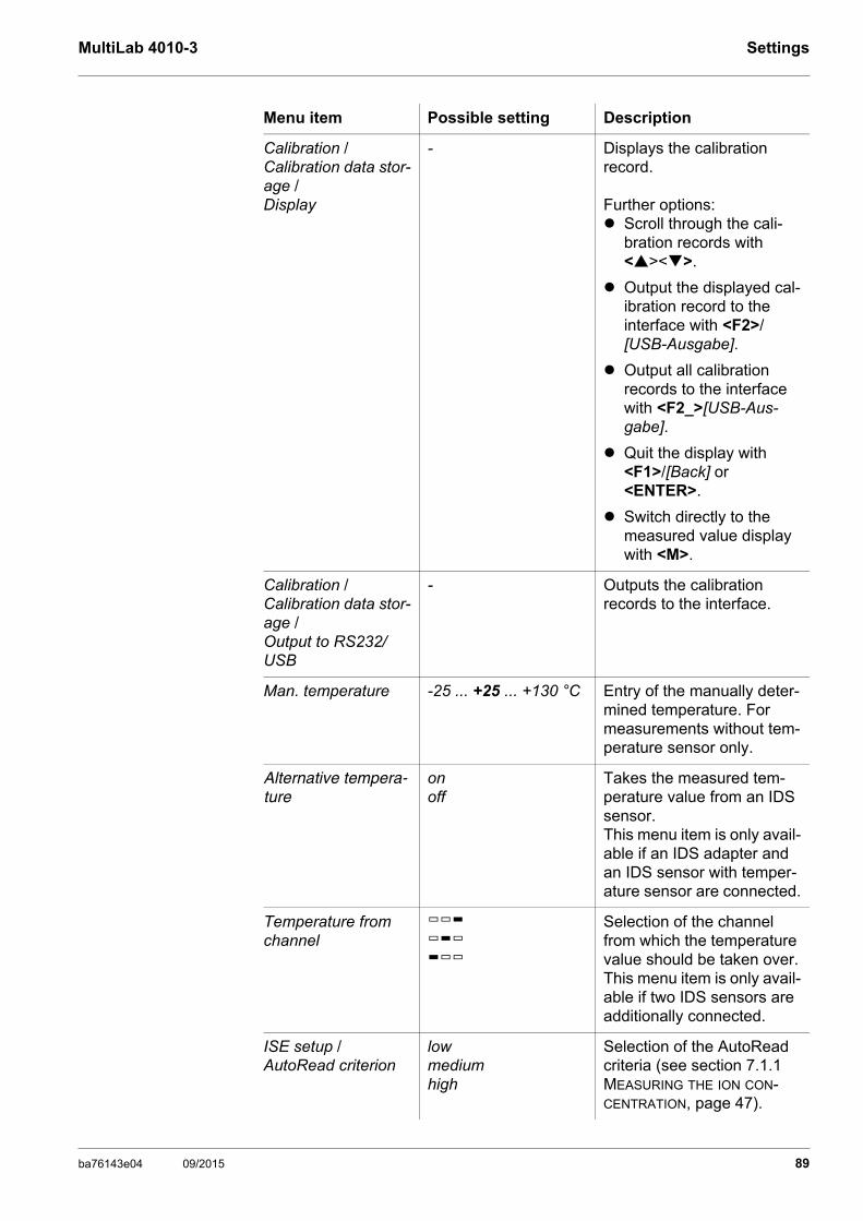
MultiLab 4010-3 Settings
Calibration / Calibration data stor-age /Display
- Displays the calibration record.
Further options: Scroll through the cali-
bration records with <><>.
Output the displayed cal-ibration record to the interface with <F2>/[USB-Ausgabe].
Output all calibration records to the interface with <F2_>[USB-Aus-gabe].
Quit the display with <F1>/[Back] or <ENTER>.
Switch directly to the measured value display with <M>.
Calibration / Calibration data stor-age /Output to RS232/USB
- Outputs the calibration records to the interface.
Man. temperature -25 ... +25 ... +130 °C Entry of the manually deter-mined temperature. For measurements without tem-perature sensor only.
Alternative tempera-ture
onoff
Takes the measured tem-perature value from an IDS sensor.This menu item is only avail-able if an IDS adapter and an IDS sensor with temper-ature sensor are connected.
Temperature from channel
▭▭▬▭▬▭▬▭▭
Selection of the channel from which the temperature value should be taken over.This menu item is only avail-able if two IDS sensors are additionally connected.
ISE setup /AutoRead criterion
lowmediumhigh
Selection of the AutoRead criteria (see section 7.1.1 MEASURING THE ION CON-CENTRATION, page 47).
Menu item Possible setting Description
ba76143e04 09/2015 89

Settings MultiLab 4010-3
ISE setup /Ion type
Ag, Br, Ca, Cd, Cl, CN, Cu, F, I, K, Na, NO3, Pb, S, NH3, NH4*, CO2, ION
Selection of the ion type to be measured.
An ion that is not included in the list can be measured with the setting, ION.
* Measuring with the NH 500 electrode:The NH4 setting is not suitable for the gas-sensitive electrode NH 500. Select the following settings:Ion type "ION", Valency "-1".
ISE setup /Unit
mg/lµmol/lmg/kgppm%
Selection, with which unit the measurement result and calibration standards should be displayed.
ISE setup/Valency
-8 ... +8 Set the valence (Valency) and molar weight (Molar mass) for the ion (only with Unit: mg/kg, ppm, %)ISE setup/
Molar mass1 ... 300 g/mol
ISE setup/Density
0.001 ... 9.999 g/ml or kg/l
Adjustable density of the test sample (only with Unit: mg/kg, ppm, %)
Method Standard additionStandard subtractionSample additionSample subtractionBlank value addition
Selection of the available measuring methods.
Start method Start measurement with the selected method.
Menu item Possible setting Description
90 ba76143e04 09/2015

MultiLab 4010-3 Settings
10.4 D.O. measurement settings
10.4.1 Settings for D.O. measurement
The settings are available in the menu for measurement and calibration set-tings. To open the settings, display the required measured parameter in the measured value display and press the <ENTER> key. After completing the set-tings, switch to the measured value display with <M>.
10.4.2 Enter Sensor Cap coefficients
10.4.3 Saturation local
Irrespective of the height or air pressure, the calibration value is set to 100%. Saturation local is ideal for EU compliance.
When Saturation local is enabled, an L will appear next to D.O.% on the display.
D.O. mg/L readings are unaffected by the selection of Saturation local.
10.5 Cond measurement settings
10.5.1 Settings for IDS conductivity sensors
The settings are made in the menu for the measured parameter, conductivity. To open the settings, display the required measured parameter in the mea-sured value display and press the <ENTER> key. After completing the settings, switch to the measured value display with <M>.The possible settings are individually displayed for each sensor. Below the set-ting menu is displayed for two IDS sensors (4310, 4320).Default settings are printed in bold.
Setting menu of4310
The values of the coefficients are provided with the sensor cap.
1. Change the digit of the highlighted position with <><>.
2. Go to the next position with <><>.
3. Confirm with<ENTER> when a coefficient is completely entered.
Menu item Possible setting
Explanation
Calibration /Calibra-tion record
- Displays the calibration record of the last calibration.
ba76143e04 09/2015 91

Settings MultiLab 4010-3
Calibration / Calibra-tion data storage / Display
- Displays the last calibration records (max. 10)
Calibration / Calibra-tion data storage / Output to USB flash drive or printer
- Outputs the stored calibration data to the USB-A interface (USB memory device/USB printer)
Calibration / Calibration data stor-age / Output to RS232/USB
- Outputs the stored calibration data to the USB-B interface (PC)
Calibration /Calibra-tion interval
1 ... 150 ... 999 d
Calibration interval for the IDS con-ductivity sensor (in days).The meter reminds you to calibrate regularly by the flashing sensor sym-bol in the measuring screen.
Type Used measuring cell
Cal Measuring cells whose cell constant is determined by calibration in the KCl control standard solution.Calibration range:0.450 to 0.500 cm-1
The currently valid cell constant is dis-played in the status line.
man Freely adjustable cell constant in the range 0.450 ... 0.500 cm-1.
Man. cell const. 0.450 ... 0.475 ... 0.500 cm-1
Display and setting options for the cell constant.
Temp. comp. (TC) /Method
nLFlinoff
Procedure for temperature compen-sation (see section 9.2 TEMPERATURE COMPENSATION, page 79).This setting is only available for the measured parameters, ϰ and ρ.
Temp. comp. (TC) /Linear coeff.
0.000 ... 2.000 ... 3.000 %/K
Coefficient of the linear temperature compensation.This menu item is only available when the linear temperature compensation is set.
Temp. comp. (TC) /Reference temp.
20 °C25 °C
Reference temperatureThis setting is only available for the measured parameters, ϰ and ρ.
Multiplier for TDS 0.40 ... 1.00 Factor for TDS value
Menu item Possible setting
Explanation
92 ba76143e04 09/2015
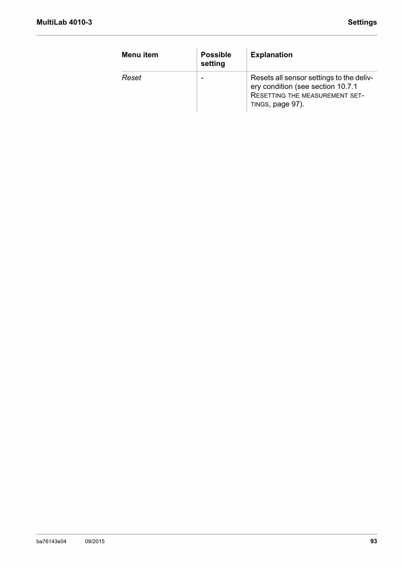
MultiLab 4010-3 Settings
Reset - Resets all sensor settings to the deliv-ery condition (see section 10.7.1 RESETTING THE MEASUREMENT SET-TINGS, page 97).
Menu item Possible setting
Explanation
ba76143e04 09/2015 93
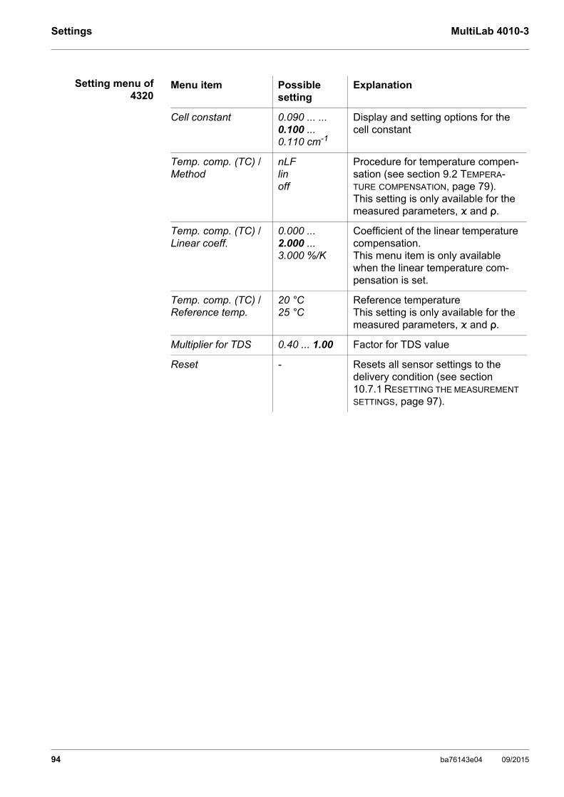
Settings MultiLab 4010-3
Setting menu of4320
Menu item Possible setting
Explanation
Cell constant 0.090 ... ... 0.100 ... 0.110 cm-1
Display and setting options for the cell constant
Temp. comp. (TC) /Method
nLFlinoff
Procedure for temperature compen-sation (see section 9.2 TEMPERA-TURE COMPENSATION, page 79).This setting is only available for the measured parameters, ϰ and ρ.
Temp. comp. (TC) /Linear coeff.
0.000 ... 2.000 ... 3.000 %/K
Coefficient of the linear temperature compensation.This menu item is only available when the linear temperature com-pensation is set.
Temp. comp. (TC) /Reference temp.
20 °C25 °C
Reference temperatureThis setting is only available for the measured parameters, ϰ and ρ.
Multiplier for TDS 0.40 ... 1.00 Factor for TDS value
Reset - Resets all sensor settings to the delivery condition (see section 10.7.1 RESETTING THE MEASUREMENT SETTINGS, page 97).
94 ba76143e04 09/2015

MultiLab 4010-3 Settings
10.6 Sensor-independent settings
10.6.1 System
To open the Storage & config menu, press the <ENTER_> key in the measured value display. After completing the settings, switch to the measured value dis-play with <M>. Default settings are printed in bold.
Menu item Setting Explanation
System / General / Language DeutschEnglish(more)
Selects the menu language
System / General / Audio signal onoff
Switches on/off the beep on key-stroke
System / General / Brightness 0 ... 10 ... 22 Changes the display brightness
System / General / Tempera-ture unit
°C °F
Temperature unit, degrees Celsius or degrees Fahren-heit.All temperature values are displayed with the selected unit.
System / General / Stability control
onoff
Switches on or off the automatic sta-bility control during measurement (see section 10.6.3 AUTOMATIC STA-BILITY CONTROL, page 96 )
System / Interface / Baud rate 1200, 2400, 4800, 9600, 19200
Baud rate of the USB Device inter-face
System / Interface / Output for-mat
ASCIICSV
Output format for data transmissionFor details, see section 12 TRANSMIT-TING DATA, page 107
System / Interface / Decimal separator
Dot (xx.x)Comma (xx,x)
Decimal separator
System / Interface / Output header
Output of a header for Output format: CSV
System /Clock function Date formatDatumTime
Settings of time and date. For details, see section 4.5.5 EXAMPLE 2 ON NAVIGATION: SETTING THE DATE AND TIME, page 25
System /Service information Hardware version and software ver-sion of the meter are displayed.
System /Reset - Resets the system settings to the default values. For details, see section 10.7.2 RESETTING THE SYSTEM SETTINGS, page 100
ba76143e04 09/2015 95

Settings MultiLab 4010-3
10.6.2 Data storage
This menu contains all functions to display, edit and erase stored measured values.
10.6.3 Automatic Stability control
The automatic Stability control (AutoRead) function continuously checks the stability of the measurement signal. The stability has a considerable impact on the reproducibility of measured values.
You can activate or switch off the automatic Stability control function (see section 10.6 SENSOR-INDEPENDENT SETTINGS, page 95).
The measured parameter flashes on the display
as soon as the measured value is outside the stability range
when you switch over between the measured parameters with <M>.
when the automatic Stability control is switched off.
Detailed information on the memory functions of the MultiLab 4010-3 are given in section 11 DATA STORAGE, page 101.
96 ba76143e04 09/2015
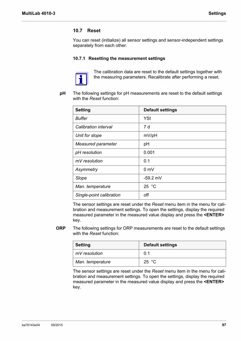
MultiLab 4010-3 Settings
10.7 Reset
You can reset (initialize) all sensor settings and sensor-independent settings separately from each other.
10.7.1 Resetting the measurement settings
pH The following settings for pH measurements are reset to the default settings with the Reset function:
The sensor settings are reset under the Reset menu item in the menu for cali-bration and measurement settings. To open the settings, display the required measured parameter in the measured value display and press the <ENTER> key.
ORP The following settings for ORP measurements are reset to the default settings with the Reset function:
The sensor settings are reset under the Reset menu item in the menu for cali-bration and measurement settings. To open the settings, display the required measured parameter in the measured value display and press the <ENTER> key.
The calibration data are reset to the default settings together with the measuring parameters. Recalibrate after performing a reset.
Setting Default settings
Buffer YSI
Calibration interval 7 d
Unit for slope mV/pH
Measured parameter pH
pH resolution 0.001
mV resolution 0.1
Asymmetry 0 mV
Slope -59.2 mV
Man. temperature 25 °C
Single-point calibration off
Setting Default settings
mV resolution 0.1
Man. temperature 25 °C
ba76143e04 09/2015 97

Settings MultiLab 4010-3
ISE The following settings for ISE measurements are reset to the default settings with the Reset function:
The sensor settings are reset under the Reset menu item in the menu for cali-bration and measurement settings. To open the settings, display the required measured parameter in the measured value display and press the <ENTER> key.
Dissolved oxygen The following settings for D.O. measurements are reset to the default settings with the Reset function:
The sensor settings are reset under the Reset menu item in the menu for cali-bration and measurement settings. To open the settings, display the required measured parameter in the measured value display and press the <ENTER> key.
Conductivity The following settings for conductivity measurements are reset to the default settings with the Reset function:
Setting Default settings
AutoRead criterion high
Ion type Ag
Unit mg/l
Man. temperature 25 °C
Alternative temperature off
Method Standard addition
Setting Default settings
Calibration interval 180 d
Check interval 60 d
Measured parameter D.O. concentration
Relative slope (SRel) 1.00
Salinity (value) 0.0
Salinity (function) Off
Setting Default settings
Calibration interval 150 d
Measured parameter ϰ
Cell constant (c) Depending on the connected mea-suring cell:0.475 cm-1 (calibrated)0.475 cm-1 (set)0.100 cm-1
Temperature compensation nLF
98 ba76143e04 09/2015

MultiLab 4010-3 Settings
The sensor settings are reset under the Reset menu item in the menu for cali-bration and measurement settings. To open the settings, display the required measured parameter in the measured value display and press the <ENTER> key.
Reference temperature 25 °C
Temperature coefficient (TC) of the linear temperature compensation
2.000 %/K
Multiplier for TDS 1.00
Setting Default settings
ba76143e04 09/2015 99

Settings MultiLab 4010-3
10.7.2 Resetting the system settings
The following system settings can be reset to the default condition:
The system settings are reset in the menu, Storage & config / System / Reset. To open the Storage & config menu, press the <ENTER_> key in the measured value display.
Setting Default settings
Language English
Audio signal on
Baud rate 4800 Baud
Output format ASCII
Decimal separator Dot (xx.x)
Brightness 10
Temperature unit °C
Stability control on
100 ba76143e04 09/2015

MultiLab 4010-3 Data storage
11 Data storage
You can transmit measured values (datasets) to the data storage:
Manual data storage (see section 11.1 MANUAL DATA STORAGE, page 101)
Automatic data storage at intervals (see section 11.2 AUTOMATIC DATA STO-RAGE AT INTERVALS, page 101)
11.1 Manual data storage
You can transmit a measurement dataset to the data storage as follows. The dataset is at the same time output to the interface:
If the storage is full When all storage locations are occupied, it is not possible to continue storing. Then you can e.g. transmit the stored data to a PC or a USB flash drive (see section 11.3.1 EDITING THE MEASUREMENT DATA STORAGE, page 104) and sub-sequently erase the storage (see section 11.3.2 ERASING THE MEASUREMENT DATA STORAGE, page 105).
11.2 Automatic data storage at intervals
The storage interval (Interval) determines the time interval between automatic data storage processes. Each data storage process transmits the current data-set to the interface at the same time.
Configuring theautomatic storage
function
1. Press the <STO> key shortly.The menu for manual data storage appears.
2. If necessary, change and confirm the ID number (1 ... 10000) with <><> and <ENTER>.The dataset is stored. The meter switches to the measured value dis-play.
03.04.2013 11:24:16
pH 7.000 24.8 °C AR +++
ID number: 1continue
Manual data storage 4 von 500
01.08.2015 08:00
1. Press the <STO_> key.The menu for automatic data storage appears.
ba76143e04 09/2015 101
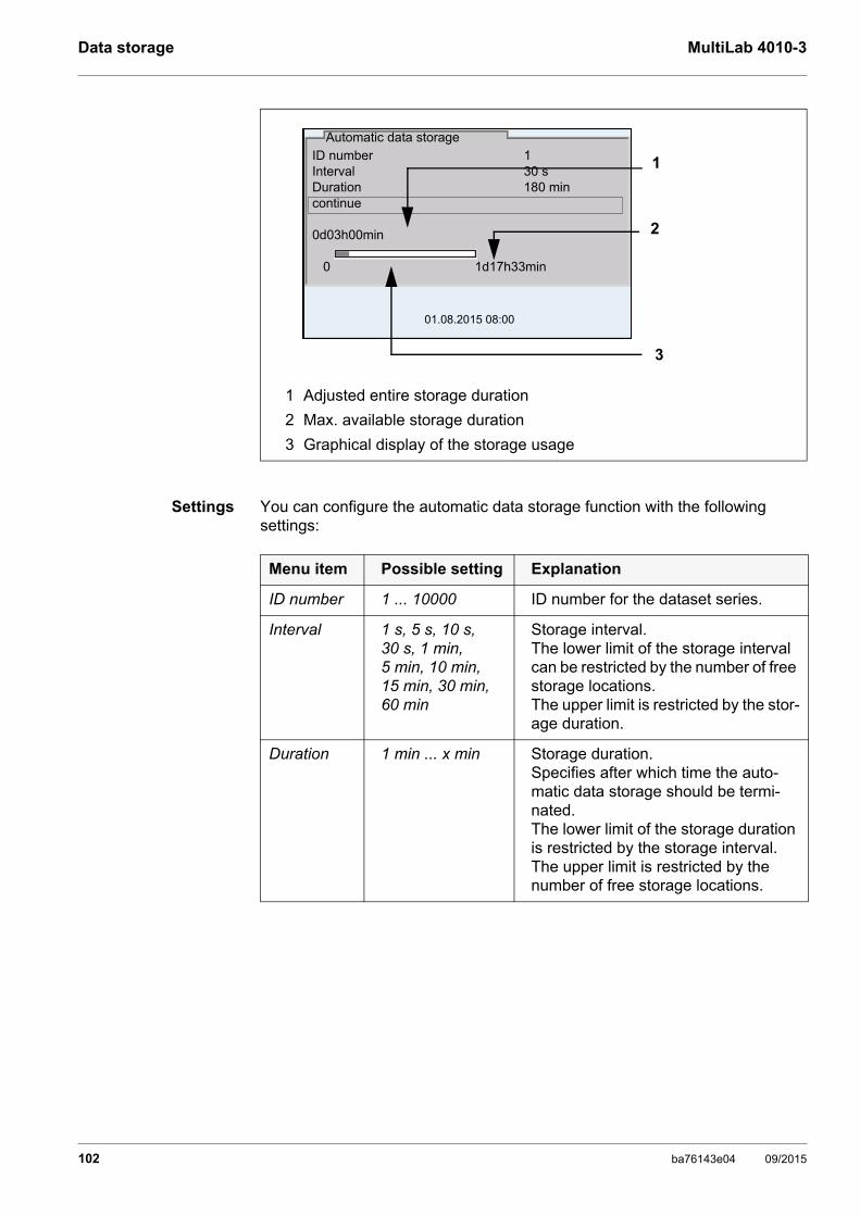
Data storage MultiLab 4010-3
Settings You can configure the automatic data storage function with the following settings:
1 Adjusted entire storage duration
2 Max. available storage duration
3 Graphical display of the storage usage
ID number 1Interval 30 sDuration 180 mincontinue
0d03h00min
0 1d17h33min
Automatic data storage
01.08.2015 08:00
1
2
3
Menu item Possible setting Explanation
ID number 1 ... 10000 ID number for the dataset series.
Interval 1 s, 5 s, 10 s, 30 s, 1 min, 5 min, 10 min, 15 min, 30 min, 60 min
Storage interval.The lower limit of the storage interval can be restricted by the number of free storage locations.The upper limit is restricted by the stor-age duration.
Duration 1 min ... x min Storage duration.Specifies after which time the auto-matic data storage should be termi-nated.The lower limit of the storage duration is restricted by the storage interval.The upper limit is restricted by the number of free storage locations.
102 ba76143e04 09/2015

MultiLab 4010-3 Data storage
Starting theautomatic storage
function
To start the automatic storage function, select continue with <><> and con-firm with <ENTER>. The meter switches to the measured value display.
The active automatic data storage function can be recognized by the progress bar in the status line. The progress bar indicates the remaining storage dura-tion.
Terminating theautomatic storage
function prema-turely
Proceed as follows to switch off the automatic data storage function before the adjusted storage duration has expired:
1 Remaining storage duration
2 Graphical display of the storage duration
If the automatic data storage function is activated, only the follow-ing keys are active: <M>, <STO_> and <On/Off>. The other keys and the automatic switch-off function are deactivated.
01.08.2013 08:00
0d03h00min
1
01.08.2013 08:00
0d03h00min
2
1. Press the <STO_> key.The following window appears.
2. Using <><>, select yes and confirm with <ENTER>.The meter switches to the measured value display.The automatic data storage function is terminated.
Stop automatic storage?
yesno
Warning
01.08.2015 08:00
ba76143e04 09/2015 103
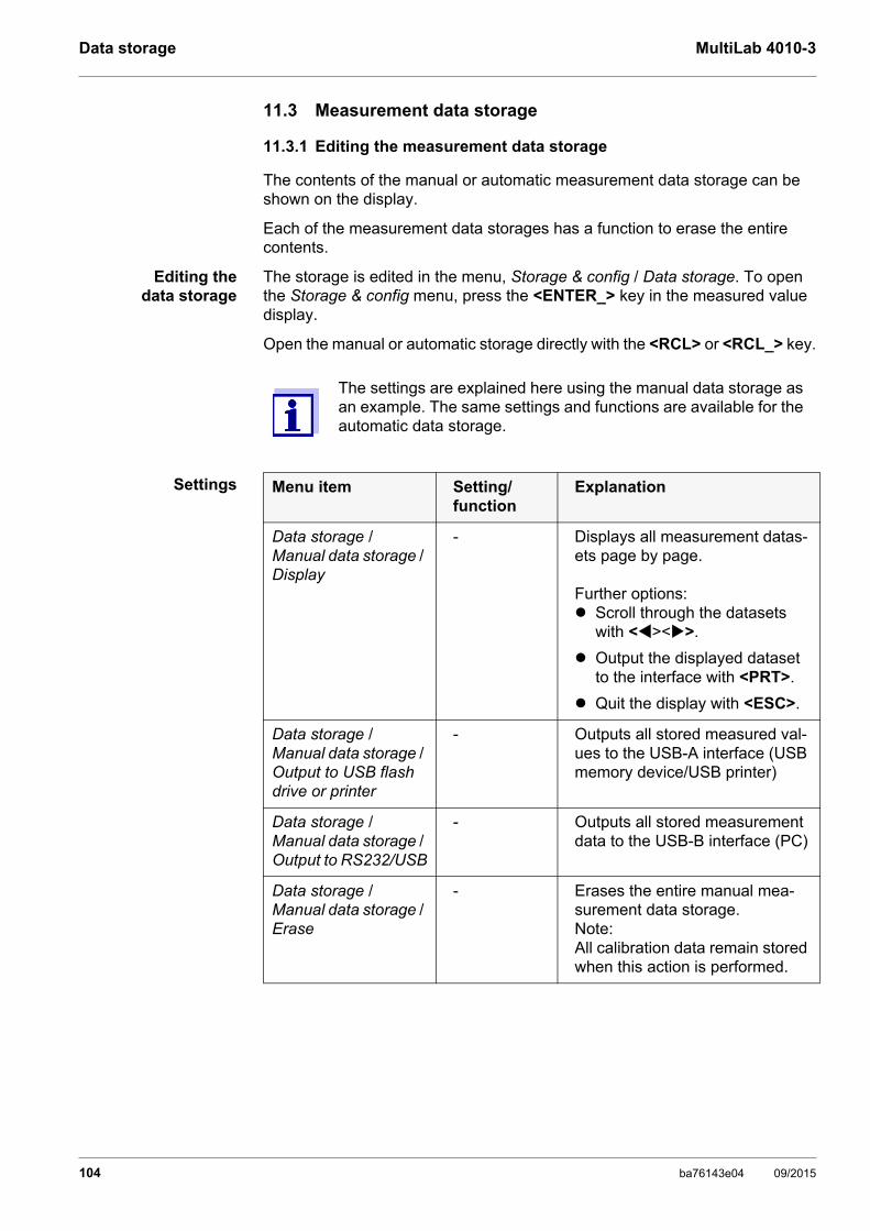
Data storage MultiLab 4010-3
11.3 Measurement data storage
11.3.1 Editing the measurement data storage
The contents of the manual or automatic measurement data storage can be shown on the display.
Each of the measurement data storages has a function to erase the entire contents.
Editing thedata storage
The storage is edited in the menu, Storage & config / Data storage. To open the Storage & config menu, press the <ENTER_> key in the measured value display.
Open the manual or automatic storage directly with the <RCL> or <RCL_> key.
Settings
The settings are explained here using the manual data storage as an example. The same settings and functions are available for the automatic data storage.
Menu item Setting/function
Explanation
Data storage / Manual data storage / Display
- Displays all measurement datas-ets page by page.
Further options: Scroll through the datasets
with <><>.
Output the displayed dataset to the interface with <PRT>.
Quit the display with <ESC>.
Data storage / Manual data storage / Output to USB flash drive or printer
- Outputs all stored measured val-ues to the USB-A interface (USB memory device/USB printer)
Data storage / Manual data storage / Output to RS232/USB
- Outputs all stored measurement data to the USB-B interface (PC)
Data storage / Manual data storage / Erase
- Erases the entire manual mea-surement data storage.Note:All calibration data remain stored when this action is performed.
104 ba76143e04 09/2015

MultiLab 4010-3 Data storage
Display presentationof a dataset
Sample printout
Quitting the display To quit the display of stored measurement datasets, you have the following options:
Switch directly to the measured value display with <M>.
Quit the display and move to the next higher menu level with <ESC>.
11.3.2 Erasing the measurement data storage
How to erase the measured value storage is described in section 11.3.1 EDITING THE MEASUREMENT DATA STORAGE, page 104.
11.3.3 Measurement dataset
A complete dataset includes:
Date/time
Meter name, series number
Sensor name, series number
ID number
Manual data storage 3 of 6403.04.2013 11:24:16 ID number: 1
4110 B20294008565pH 7.000 24.8 °C AR Sensor: +++
01.08.2015 08:00
03.04.2013 09:56:20MultiLab 4010-3 Ser. no. 09250023
4110Ser. no. B092500013ID number 2pH 6.012 24.8 °C, AR, Sensor: +++________________________________________
03.04.2013 10:56:20MultiLab 4010-3 Ser. no. 09250013
4110Ser. no. B092500013ID number 2pH 6.012 24.8 °C, AR, Sensor: +++________________________________________
etc...
ba76143e04 09/2015 105

Data storage MultiLab 4010-3
Measured value of the connected sensor
Measured temperature value of the connected sensor
AutoRead info: AR appears with the measured value if the AutoRead crite-rion was met while storing (stable measured value). Otherwise, the AR dis-play is missing.
Calibration evaluation: - 4 levels (+++, ++, +, -, or no evaluation) or- QSC (percentage)
11.3.4 Storage locations
The MultiLab 4010-3 meter has two measurement data storages. The measured values recorded either manually or automatic are stored separately in individual measurement data storages.
Storage Maximum number of datasets
Manual data storage 500
Automatic data storage 10000
106 ba76143e04 09/2015
MultiLab 4010-3 Transmitting data
12 Transmitting data
12.1 Outputting current measurement data
12.2 Transmitting data
The meter has the following interfaces:
USB-B interface (USB Device)e.g. to connect a PC
USB-A interface (USB Host), e.g. to connect a USB flash drive/USB printer
Via the USB-B interface (USB Device) you can transmit data to a PC or printer and update the meter software.
Via the USB-A interface (USB Host) it is possible to transfer data to an external USB memory device/USB printer.
12.3 Connecting the PC / USB-B interface (USB Device)
Connect the MultiLab 4010-3 to the PC via the USB-B interface.
Installation of theUSB driver on the
PC
System requirements of the PC for installation of the USB driver:
PC with at least one free USB connection and CD-ROM drive
Windows 2000, Windows XP, Windows Vista or Windows 7.
1. Output the current measurement data to an interface with <PRT>. USB-B: e.g.: PC
USB-A: e.g.: printer or USB flash drive (if no PC is connected)
1. Insert the supplied installation CD in the CD drive of your PC.
2. Install the driver from the CD.Follow the Windows installation instructions as necessary.
3. Connect the MultiLab 4010-3 to the PC via the USB-B interface.The meter is listed as a virtual COM interface among the connections in the Windows instrument manager.
ba76143e04 09/2015 107
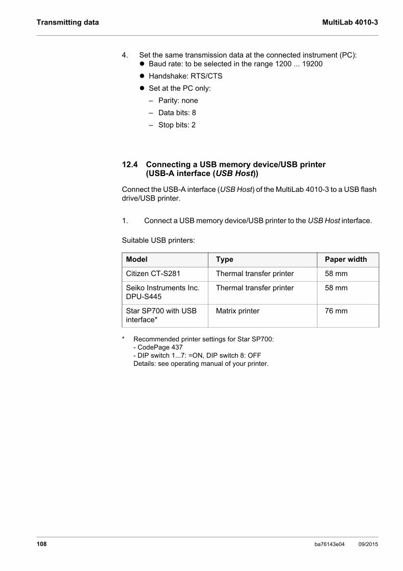
Transmitting data MultiLab 4010-3
12.4 Connecting a USB memory device/USB printer (USB-A interface (USB Host))
Connect the USB-A interface (USB Host) of the MultiLab 4010-3 to a USB flash drive/USB printer.
Suitable USB printers:
4. Set the same transmission data at the connected instrument (PC): Baud rate: to be selected in the range 1200 ... 19200
Handshake: RTS/CTS
Set at the PC only:
– Parity: none
– Data bits: 8
– Stop bits: 2
1. Connect a USB memory device/USB printer to the USB Host interface.
Model Type Paper width
Citizen CT-S281 Thermal transfer printer 58 mm
Seiko Instruments Inc. DPU-S445
Thermal transfer printer 58 mm
Star SP700 with USB interface*
* Recommended printer settings for Star SP700:- CodePage 437- DIP switch 1...7: =ON, DIP switch 8: OFFDetails: see operating manual of your printer.
Matrix printer 76 mm
108 ba76143e04 09/2015

MultiLab 4010-3 Transmitting data
12.5 Options for data transmission to the USB-B (PC) interface and the USB-A (USB printer) interface
Via the USB-B interface you can transmit data to a PC. Via the USB-A interface, you can transmit data to a USB printer or USB mem-ory device. How to transmit data to a USB memory device is described in an extra section (see section 12.6 DATA TRANSMISSION TO THE USB-A INTERFACE (USB MEMORY DEVICE), page 110).
The following table shows which data are transmitted to the interface in which way:
Data Control Operation / description
Currentmeasured values of all connected sensors
Manual With <PRT>.
Simultaneously with every manual data storage process (see section 11.1 MANUAL DATA STORAGE, page 101).
Automatic, at intervals
With <PRT_>. Then you can set the transmission interval.
Simultaneously with every automatic data storage process (see section 11.2 AUTOMATIC DATA STORAGE AT INTERVALS, page 101).
Stored mea-sured values
Manual Displayed dataset with <PRT> after calling up from the storage.
All datasets with the Output to RS232/USB function. (see section 11.3.1 EDITING THE MEASUREMENT DATA STORAGE, page 104).
All datasets with the Output to USB flash drive or printer function (USB-A interface)
For details, see section 11.3.1 EDITING THE MEASUREMENT DATA STORAGE, page 104.
Calibration records
Manual Displayed calibration record with <PRT> (see section 5.2.6 CALI-BRATION DATA, page 36; section 8.2.6 CALIBRATION DATA, page 74; section 9.3.4 CALIBRATION DATA, page 81).
All calibration records with the Output to USB flash drive or printer function.
All calibration records with <PRT_>.
For details, see section 12 TRANSMITTING DATA, page 107.
Automatic At the end of a calibration procedure.
The following rule applies: With the exception of the menus, shortly pressing the <PRT> key generally outputs the display contents to the interface (displayed measured values, measurement datasets, calibration records).
ba76143e04 09/2015 109

Transmitting data MultiLab 4010-3
12.6 Data transmission to the USB-A interface (USB memory device)
Via the USB-A interface, you can transmit data to a USB memory or USB printer device. How to transmit data to a USB printer device is described in an extra section (see section 12.6 DATA TRANSMISSION TO THE USB-A INTERFACE (USB MEMORY DEVICE), page 110).
The following table shows which data are transmitted to the interface in which way:
12.7 MultiLab Importer
With the aid of the MultiLab Importer software, you can record and evaluate measurement data with a PC.
12.8 BOD Analyst Pro
With the aid of the BOD Analyst Pro software you can administrate BOD measurement on the PC and automatically calculate the measured values.
Data Control Operation / description
Stored mea-sured values
Manual All datasets with the Output to RS232/USB function.For details, see section 11.3.1 EDITING THE MEASUREMENT DATA STORAGE, page 104
Calibration data storage
Manual All stored calibration records of a sensor with the Calibr. data storage to USB flash drive function.For details, see menu for calibration and measurement settings of the sensor.
More detailed information can be found in the MultiLab Importer operating manual.
More detailed information can be found in the BOD Analyst Pro operating manual.
110 ba76143e04 09/2015

MultiLab 4010-3 Maintenance, cleaning, disposal
13 Maintenance, cleaning, disposal
13.1 Maintenance
13.1.1 General maintenance activities
The only maintenance activity required is exchanging the battery that buffers the system clock.
13.1.2 Exchanging the battery
The MultiLab 4010-3 has a battery (CR2032 type) to buffer the system clock in case of a power failure.
See the relevant operating manuals of the IDS sensors for instruc-tions on maintenance.
To retain the current setting of the date and time during the battery exchange, supply the meter with power with the power pack while changing the battery.
To avoid that the system clock is reset in the case of a power failure, we recommend changing the battery before the end of its service life (the battery included in the scope of delivery after approx. 8 years).
1. Unscrew the screws (2) of the lid of the battery compartment with a screwdriver.
1
2
ba76143e04 09/2015 111
Maintenance, cleaning, disposal MultiLab 4010-3
13.2 Cleaning
Occasionally wipe the outside of the measuring instrument with a damp, lint-free cloth. Disinfect the housing with isopropanol as required.
13.3 Packing
This meter is sent out in a protective transport packing. We recommend: Keep the packing material. The original packing protects the meter against damage during transport.
13.4 Disposal
At the end of its operational lifetime, the meter must be returned to thedisposal or return system statutory in your country. If you have any questions,please contact your supplier.
2. Open the battery compartment (1) on the underside of the meter.
3. Remove the battery from the battery compartment.
4. Insert a new battery in the battery compartment.
5. Close the battery compartment (1).The date (day) flashes on the display.
6. Tighten the screws (2) of the lid of the battery compartment with a screwdriver.
7. Set the date and time (see 4.5.5 EXAMPLE 2 ON NAVIGATION: SETTING THE DATE AND TIME, PAGE 25)
Dispose of used batteries according to the local regulations of your country.
End users within the European Union are obligated to return used batteries (even ecologically compatible ones) to a collection point set up for recycling purposes.
Batteries are marked with the crossed-out waste containersymbol. Therefore, they may not be disposed with the domestic waste.
CAUTIONThe housing is made of synthetic material (ABS). Thus, avoid contact with acetone or similar detergents that contain sol-vents. Remove any splashes immediately.
112 ba76143e04 09/2015
MultiLab 4010-3 Maintenance, cleaning, disposal
ba76143e04 09/2015 113
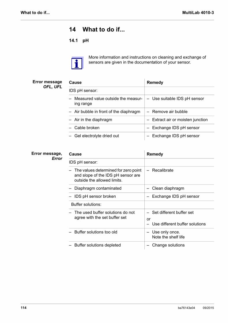
What to do if... MultiLab 4010-3
14 What to do if...
14.1 pH
Error messageOFL, UFL
Error message,Error
More information and instructions on cleaning and exchange of sensors are given in the documentation of your sensor.
Cause Remedy
IDS pH sensor:
– Measured value outside the measur-ing range
– Use suitable IDS pH sensor
– Air bubble in front of the diaphragm – Remove air bubble
– Air in the diaphragm – Extract air or moisten junction
– Cable broken – Exchange IDS pH sensor
– Gel electrolyte dried out – Exchange IDS pH sensor
Cause Remedy
IDS pH sensor:
– The values determined for zero point and slope of the IDS pH sensor are outside the allowed limits.
– Recalibrate
– Diaphragm contaminated – Clean diaphragm
– IDS pH sensor broken – Exchange IDS pH sensor
Buffer solutions:
– The used buffer solutions do not agree with the set buffer set
– Set different buffer set
or– Use different buffer solutions
– Buffer solutions too old – Use only once.Note the shelf life
– Buffer solutions depleted – Change solutions
114 ba76143e04 09/2015

MultiLab 4010-3 What to do if...
No stable measuredvalue
Obviously incorrectmeasured values
Cause Remedy
IDS pH sensor:
– Diaphragm contaminated – Clean diaphragm
– Membrane contaminated – Clean membrane
Test sample:
– pH value not stable – Measure with air excluded if necessary
– Temperature not stable – Adjust temperature if necessary
IDS pH sensor + test sample:
– Conductivity too low – Use suitable IDS pH sensor
– Temperature too high – Use suitable IDS pH sensor
– Organic liquids – Use suitable IDS pH sensor
Cause Remedy
IDS pH sensor:
– IDS pH sensor unsuitable – Use suitable IDS sensor
– Temperature difference between buffer and test sample too great
– Adjust temperature of buffer or sample solutions
– Measurement procedure not suit-able
– Follow special procedure
ba76143e04 09/2015 115

What to do if... MultiLab 4010-3
14.2 ISE
Error message OFL
Obviously incorrectmeasured values
Error message,Error (invalid
calibration)or
Calibrationevaluation poor (-)
Cause Remedy
– Measuring range exceeded – Dilute the test sample
Cause Remedy
– Electrode not connected – Connect the electrode
– Cable broken – Replace the electrode
Cause Remedy
ISE electrode:
– Moisture in the plug – Dry the plug
– Electrode is old – Replace the electrode
– Electrode not suitable for the range to be measured
– Use a suitable electrode
– Electrode not suitable for the selected ion
– Use a suitable electrode or select a suitable ion
– Socket damp – Dry the socket
– Electrode needs maintenance – Use service and storage recom-mendations in the electrode manual.
– Replace internal fill solution and/or the sensor module (if replace-able).
– Refill hole is not open – Open the refill hole (if equipped) during use
– Electrode junction not in solution – The outer junction should be completely immersed in stan-dard or sample.
– Level of internal fill solution (if refillable) must be higher than the level of standard or sample.
Calibration procedure:
– Wrong sequence of standards for three point calibration
– Select the correct sequence
– Calibration standards do not have the correct temperature (max. ± 2 °C temperature difference)
– Adjust the temperature of the calibration standards
116 ba76143e04 09/2015
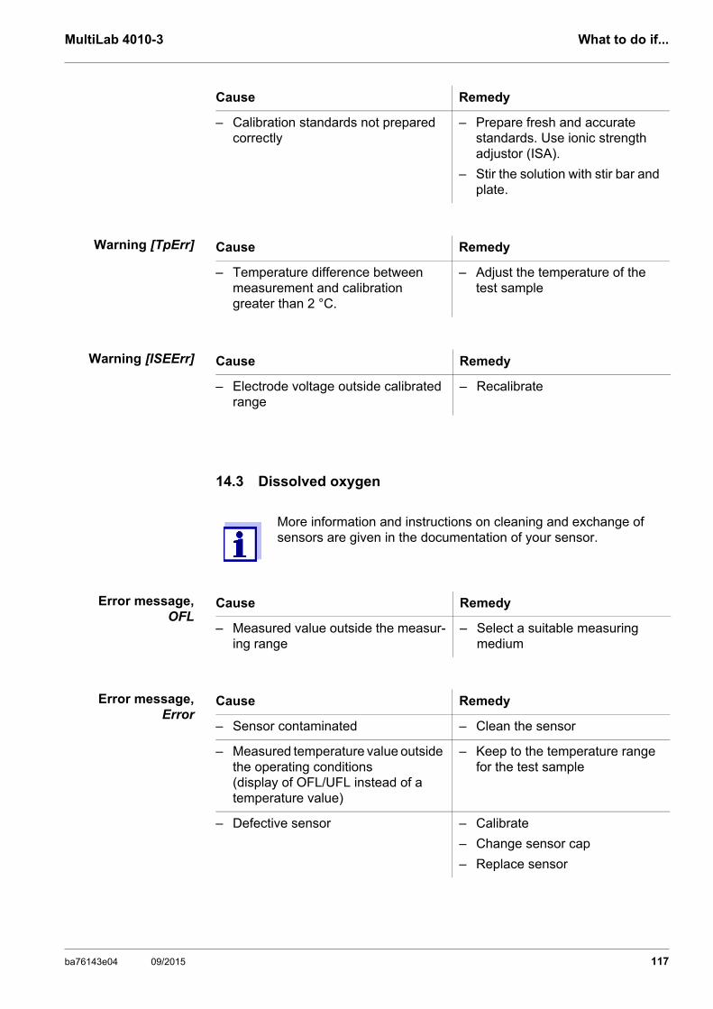
MultiLab 4010-3 What to do if...
Warning [TpErr]
Warning [ISEErr]
14.3 Dissolved oxygen
Error message,OFL
Error message,Error
– Calibration standards not prepared correctly
– Prepare fresh and accurate standards. Use ionic strength adjustor (ISA).
– Stir the solution with stir bar and plate.
Cause Remedy
Cause Remedy
– Temperature difference between measurement and calibration greater than 2 °C.
– Adjust the temperature of the test sample
Cause Remedy
– Electrode voltage outside calibrated range
– Recalibrate
More information and instructions on cleaning and exchange of sensors are given in the documentation of your sensor.
Cause Remedy
– Measured value outside the measur-ing range
– Select a suitable measuring medium
Cause Remedy
– Sensor contaminated – Clean the sensor
– Measured temperature value outside the operating conditions(display of OFL/UFL instead of a temperature value)
– Keep to the temperature range for the test sample
– Defective sensor – Calibrate
– Change sensor cap
– Replace sensor
ba76143e04 09/2015 117

What to do if... MultiLab 4010-3
14.4 Conductivity
Error message,OFL
Error message,Error
14.5 General information
Sensor symbolflashes
Meter does not reactto keystroke
You want to knowwhich software
version is in themeter or IDS sensor
More information and instructions on cleaning and exchange of sensors are given in the documentation of your sensor.
Cause Remedy
– Measured value outside the measur-ing range
– Use suitable IDS conductivity sensor
Cause Remedy
– Sensor contaminated – Clean the sensor and replace it if necessary
– Calibration solution not suitable – Check the calibration solutions
Cause Remedy
– Calibration interval expired – Recalibrate the measuring sys-tem
Cause Remedy
– Operating condition undefined or EMC load unallowed
– Processor reset:Press the <ENTER> and <On/Off> key simultaneously
Cause Remedy
– E. g., a question by the service department
– Switch on the meter.
– Open the menu, <ENTER_> / Storage & config / System / Ser-vice information. The instrument data are displayed.
or– Connect the sensor.
Press softkey [Info]/[More] The sensor data are displayed (see section 4.1.6 SENSOR INFO, page 17)
118 ba76143e04 09/2015

MultiLab 4010-3 What to do if...
Data transmission toUSB memory device
does not work
Data transmission toUSB printer does not
work
Error message,Memory error 1
Time gets lost
Cause Remedy
– Connected USB memory device was not recognized
– The USB-B interface is connected to a PC
– The USB memory device has been formatted to a file system which is not supported, e. g. NTFS
– Use other USB memory device
– Disconnect the PC from the USB-B interface
– Reformat the USB memory device to FAT 16 or FAT 32 file system(Caution: Reformatting erases all data on the USB memory device. Back up all data before reformatting.)
Cause Remedy
– The USB-B interface is connected to a PC
– Connected USB memory device does not work
– Disconnect the PC from the USB-B interface
– Use a suitable USB printer (see section 12.4 CONNECTING A USB MEMORY DEVICE/USB PRINTER (USB-A INTERFACE (USB HOST)), page 108)
– Check printer settings (see sec-tion 12.4 CONNECTING A USB MEMORY DEVICE/USB PRINTER (USB-A INTERFACE (USB HOST)), page 108)
Cause Remedy
– Instrument storage was not found – Please contact the service.
Cause Remedy
– Buffer battery is empty – Change the buffer battery (see section 13.1.1 GENERAL MAINTE-NANCE ACTIVITIES, page 111)
ba76143e04 09/2015 119

Technical data MultiLab 4010-3
15 Technical data
15.1 Measuring ranges, resolution, accuracy
15.2 General data
Measuring ranges,accuracy
Parameter Measuring range Accuracy
Air pressure (abso-lute)*
225 ... 825 mm Hg ± 3 mm Hg
*Available only if a D.O. sensor is connected
Further data are given in the documentation of your sensor.
Dimensions Approx. 180 x 80 x 55 mm (11.22 x 10.04 x 3.15 inches)
Weight Approx. 0.4 kg
Mechanical structure Type of protection IP 43
Electrical safety Protective class III
Test certificates CE, cETLus
Ambient conditions Storage - 25 °C ... + 65 °C
Operation 0 °C ... + 40 °C
Admissible relative humidity
Yearly mean: < 75 %30 days/year: 95 %Other days: 85 %
Power supply Power pack Kuantech Co. Ltd. KSAC 0900110W1UV-1Input: 100 ... 240 V ~ / 50 ... 60 Hz / 270 mAOutput: 9 V = / 1.1 AConnection max. overvoltage category IIPrimary plugs contained in the scope of delivery: Euro, US, UK and Australian.
Battery(to buffer the system clock in the case of a power failure)
3.0 V lithium manganese dioxide battery, type CR 2032
USB interface (device) Type USB 1.1USB-B (Device), PC
Baud rate Adjustable: 1200, 2400, 4800, 9600, 19200 Baud
Data bits 8
Stop bits 2
120 ba76143e04 09/2015
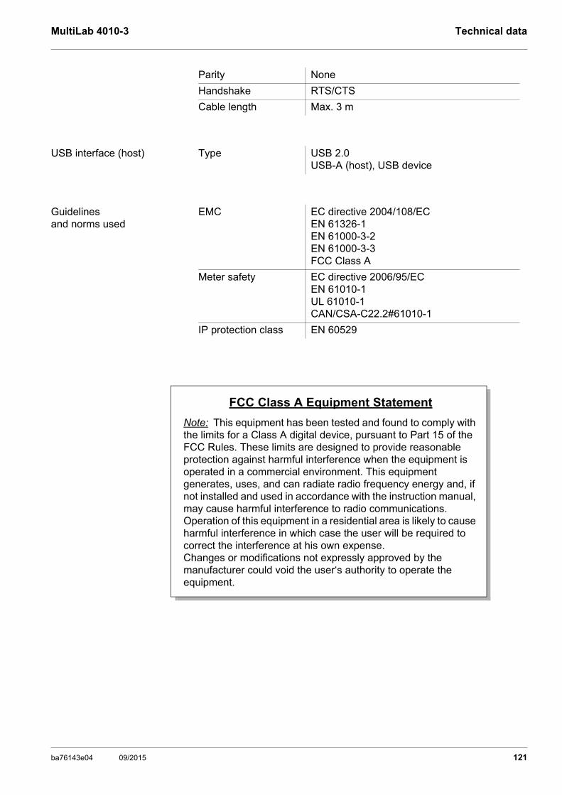
MultiLab 4010-3 Technical data
Parity None
Handshake RTS/CTS
Cable length Max. 3 m
USB interface (host) Type USB 2.0USB-A (host), USB device
Guidelinesand norms used
EMC EC directive 2004/108/ECEN 61326-1EN 61000-3-2EN 61000-3-3FCC Class A
Meter safety EC directive 2006/95/ECEN 61010-1UL 61010-1CAN/CSA-C22.2#61010-1
IP protection class EN 60529
FCC Class A Equipment Statement
Note: This equipment has been tested and found to comply with the limits for a Class A digital device, pursuant to Part 15 of the FCC Rules. These limits are designed to provide reasonable protection against harmful interference when the equipment is operated in a commercial environment. This equipment generates, uses, and can radiate radio frequency energy and, if not installed and used in accordance with the instruction manual, may cause harmful interference to radio communications. Operation of this equipment in a residential area is likely to cause harmful interference in which case the user will be required to correct the interference at his own expense.Changes or modifications not expressly approved by the manufacturer could void the user‘s authority to operate the equipment.
ba76143e04 09/2015 121

Technical data MultiLab 4010-3
Keypad (antibacterial)
LSN 25/7181515/07/2004
CERTIFICATE OF ANALYSIS
Sample Ref No.:
Date Received:
The microbiological results demonstrate that the material under test exhibits biocidal activity.Comment:
03/03/2005Date Reported:
AUTOTEX AM
Client:Autotype International LimitedGrove RoadWantageOxonOX12 7B2United Kingdom
FILM TESTMeth. Desc AUTOTYPESupplier:
Job Ref: 04I0712
xxTest Result Unit Est
Salmonella enteritidis %99.6 Reduction After 24 Hours xx
Klebsiella pneumoniae %99.4 Reduction After 24 Hours xx
Pseudomonas aeruginosa %99.1 Reduction After 24 Hours xx
Streptococcus faecalis %99.4 Reduction After 24 Hours xx
Phoma violacea %99.0 Reduction After 48 Hours xx
Penicillium purpurogenum %99.3 Reduction After 48 Hours xx
Bacillus cereus %99.3 Reduction After 24 Hours xx
Saccharmyces cerevisiae %99.3 Reduction After 24 Hours xx
04I0712/6/1/1
P.M.Sutton J. Francis
Nutritional Services Manager
Senior Microbiologist
CChem., MRSC. BSc. (Hons.)N.StantonJ.Lloyd
SeniorMicrobiologist
PrincipalMicrobiologist
C.FullerBSc. (Hons.), CBiol., MBiol.,
MIFST
Company Microbiologist
J.Elliott
SeniorMicrobiologist
BSc. (Hons.), CBiol., MBiol BSc. (Hons.)
Law Laboratories Ltd Shady Lane, Great Barr, Birmingham B44 9ET England
BSc. (Hons.)R.P.Elliott
Deputy Managing Director
CChem, MRSC, MIFST
122 ba76143e04 09/2015

MultiLab 4010-3 Technical data
LSN 26/3812324/10/2004
CERTIFICATE OF ANALYSIS
Sample Ref No.:
Date Received:
The microbiological results demonstrate that the material under test exhibits biocidal activity against the above listed microbial strains.
Comment:
21/02/2005Date Reported:
AUTOTEX AM AGED 15 YEARS
Client:Autotype International LimitedGrove RoadWantageOxonOX12 7B2United Kingdom
Harmonised JIS Z2801/AATCC 100Meth. Desc
Job Ref: 05B1760
xxx
Test Result Unit Est
Staphylococcus aureus %99.0 Reduction After 24 Hours xxx
Escherichia coli 0157 %99.8 Reduction After 24 Hours xxx
Aspergillus niger %99.1 Reduction After 48 Hours xxx
05B1760/1/3/3
P.M.Sutton J. Francis
Nutritional Services Manager
Senior Microbiologist
CChem., MRSC. BSc. (Hons.)N.StantonJ.Lloyd
SeniorMicrobiologist
PrincipalMicrobiologist
C.FullerBSc. (Hons.), CBiol., MBiol.,
MIFST
Company Microbiologist
J.Elliott
SeniorMicrobiologist
BSc. (Hons.), CBiol., MBiol BSc. (Hons.)
Law Laboratories Ltd Shady Lane, Great Barr, Birmingham B44 9ET England
BSc. (Hons.)R.P.Elliott
Deputy Managing Director
CChem, MRSC, MIFST
ba76143e04 09/2015 123

Firmware update MultiLab 4010-3
16 Firmware update
16.1 Firmware update for the meter MultiLab 4010-3
You can find available firmware update files for your meter on the Internet. With the "Firmware Update " program and a PC you can update the firmware of the MultiLab 4010-3 to the newest version.
For the update you have to connect the meter to a PC.
For the update via the USB-B interface, the following is required:
a free USB interface (virtual COM port) on the PC
the driver for the USB interface (on the enclosed CD-ROM)
the USB cable (included in the scope of delivery of the MultiLab 4010-3).
After switching the meter off and on you can check whether the meter has taken over the new software version (see YOU WANT TO KNOW WHICH SOFTWARE VERSION IS IN THE METER OR IDS SENSOR, PAGE 118).
1. Install the downloaded firmware update on a PC.An update folder is created in the Windows start menu. If an update folder already exists for the meter (or meter type), the new data are displayed there.
2. In the windows start menu, open the update folder and start the firm-ware update program for the meter
3. Using the USB interface cable, connect the MultiLab 4010-3 to a USB interface (virtual COM port) of the PC.
4. Switch on the MultiLab 4010-3.
5. In the firmware update program, start the update process with OK.
6. Follow the instructions of the firmware update program.During the programming process, a corresponding message and a progress bar (in %) are displayed. The programming process takes up to 15 minutes. A terminatory mes-sage is displayed after a successful programming process. The firm-ware update is completed.
7. Disconnect the MultiLab 4010-3 from the PC. The MultiLab 4010-3 is ready for operation again.
124 ba76143e04 09/2015
MultiLab 4010-3 Firmware update
16.2 Firmware-Update for IDS Sensors
With the "Firmware Update" program and a PC you can update the firmware of an IDS sensor to the newest version. You can find available firmware update files for your IDS sensor on the Internet.
For updating, connect the IDS sensor to the MultiLab 4010-3, and the MultiLab 4010-3 to a PC.
For the update via the USB-B interface, the following is required:
a free USB interface (virtual COM port) on the PC
the driver for the USB interface (on the enclosed CD-ROM)
the USB cable (included in the scope of delivery of the MultiLab 4010-3).
After switching the meter off and on you can check whether the sensor has taken over the new software version (see YOU WANT TO KNOW WHICH SOFTWARE VERSION IS IN THE METER OR IDS SENSOR, PAGE 118).
1. Install the downloaded firmware update on a PC.An update folder is created in the Windows start menu. If an update folder already exists for the sensor (or sensor type), the new data are displayed there.
2. In the windows start menu, open the update folder and start the firm-ware update program for the IDS sensor
3. Connect the IDS sensor to the MultiLab 4010-3 meter.
4. Using the USB interface cable, connect the MultiLab 4010-3 to a USB interface (virtual COM port) of the PC.
5. Switch on the MultiLab 4010-3.
6. In the firmware update program, start the update process with OK.
7. Follow the instructions of the firmware update program.During the programming process, a corresponding message and a progress bar (in %) are displayed. The programming process takes up to 5 minutes. A terminatory mes-sage is displayed after a successful programming process. The firm-ware update is completed.
8. Disconnect the MultiLab 4010-3 from the PC. Meter and sensor are ready for operation again.
ba76143e04 09/2015 125

Glossary MultiLab 4010-3
17 Glossary
pH/ORP/ISE
Conductivity
Asymmetry see zero point
Electromotive force ofa combination
electrode
The electromotive force U of the combination electrode is the measur-able electromotive force of an electrode in a solution. It equals the sum of all the galvanic voltages of the combination electrode. Its depen-dency on the pH results in the electrode function, which is characterized by the parameters, slope and zero point.
Junction The junction is a porous body in the housing wall of reference elec-trodes or electrolyte bridges. It arranges the electrical contact between two solutions and makes the electrolyte exchange more difficult. The expression, junction, is also used for ground or junction-less transitions.
ORP voltage (U) The ORP is caused by oxidizing or reducing substances dissolved in water if these substances become effective on an electrode surface (e. g. a gold or platinum surface).
pH value The pH value is a measure of the acidic or basic effect of an aqueous solution. It corresponds to the negative decadic logarithm of the molal hydrogen ions activity divided by the unit of the molality. The practical pH value is the value of a pH measurement.
Potentiometry Name of a measuring technique. The signal (depending on the mea-sured parameter) of the electrode is the electrical potential. The electri-cal current remains constant.
Slope The slope of a linear calibration function.
Zero point The zero point of a pH combination electrode is the pH value at which the electromotive force of the pH combination electrode at a specified temperature is zero. Normally, this is at 25 °C.
Cell constant (C) Characteristic quantity of a conductivity measuring cell, depending on the geometry.
Conductivity (ϰ) Short form of the expression, specific electrical conductivity. It corresponds to the reciprocal value of the resistivity. It is a measured value of the ability of a substance to conduct an electric current. In water analysis, the electrical conductivity is a dimension for the ionized substances in a solution.
Referencetemperature
Fixed temperature value to compare temperature-dependent measured values. For conductivity measurements, the measured value is con-verted to a conductivity value at a reference temperature of 20 °C or 25 °C.
Resistance (ρ) Short name for the electrolytic resistivity. It corresponds to the recipro-cal value of the electrical conductivity.
126 ba76143e04 09/2015

MultiLab 4010-3 Glossary
Dissolved oxygen
General information
Salinity The absolute salinity SA of seawater corresponds to the relationship of the mass of dissolved salts to the mass of the solution (in g/Kg). In prac-tice, this dimension cannot be measured directly. Therefore, the practi-cal salinity according to IOT is used for oceanographic monitoring. It is determined by measuring the electrical conductivity.
Salt content General designation for the quantity of salt dissolved in water.
Temperaturecoefficient
Value of the slope of a linear temperature function.
Temperaturecompensation
Name of a function that considers the temperature influence on the measurement and converts it accordingly. Depending on the measured parameter to be determined, the temperature compensation functions in different ways. For conductimetric measurements, the measured value is converted to a defined reference temperature. For potentiomet-ric measurements, the slope value is adjusted to the temperature of the test sample but the measured value is not converted.
α
TRef=
Meas*
1
1 + � (T - )* TRef
D.O. % saturation Short name for the relative D.O. saturation.
Salinity The absolute salinity SA of seawater corresponds to the relationship of the mass of dissolved salts to the mass of the solution (in g/Kg). In practice, this dimension cannot be measured directly. Therefore, the practical salinity according to IOT is used for oceanographic monitor-ing. It is determined by measuring the electrical conductivity.
Salt content General designation for the quantity of salt dissolved in water.
Adjusting To manipulate a measuring system so that the relevant value (e. g. the displayed value) differs as little as possible from the correct value or a value that is regarded as correct, or that the difference remains within the tolerance.
AutoRange Name of the automatic selection of the measuring range.
Calibration Comparing the value from a measuring system (e. g. the displayed value) to the correct value or a value that is regarded as correct. Often, this expression is also used when the measuring system is adjusted at the same time (see adjusting).
Measured parameter The measured parameter is the physical dimension determined by measuring, e. g. pH, conductivity or D.O. concentration.
Measured value The measured value is the special value of a measured parameter to be determined. It is given as a combination of the numerical value and unit (e. g. 3 m; 0.5 s; 5.2 A; 373.15 K).
ba76143e04 09/2015 127
Glossary MultiLab 4010-3
Molality Molality is the quantity (in Mol) of a dissolved substance in 1000 g sol-vent.
Reset Restoring the original condition of all settings of a measuring system.
Resolution Smallest difference between two measured values that can be dis-played by a meter.
Stability control(AutoRead )
Function to control the measured value stability.
Standard solution The standard solution is a solution where the measured value is known by definition. It is used to calibrate a measuring system.
Temperature function Name of a mathematical function expressing the temperature behavior of a test sample, a sensor or part of a sensor.
Test sample Designation of the test sample ready to be measured. Normally, a test sample is made by processing the original sample. The test sample and original sample are identical if the test sample was not processed.
128 ba76143e04 09/2015

MultiLab 4010-3 Index
18 Index
AAir calibration beaker . . . . . . . . . . . . . . . . . 71AutoRead . . . . . . . . . . . . . . . . . . . . . . . 70, 77
ORP . . . . . . . . . . . . . . . . . . . . . . . . 43, 45pH . . . . . . . . . . . . . . . . . . . . . . . . . 27, 48
BBattery compartment . . . . . . . . . . . . . . . . 112Blank value addition . . . . . . . . . . . . . . . . . . 66
CCalibration
Conductivity . . . . . . . . . . . . . . . . . . . . . 80ISE . . . . . . . . . . . . . . . . . . . . . . . . . . . . 50pH . . . . . . . . . . . . . . . . . . . . . . . . . 29, 46
Calibration evaluationConductivity . . . . . . . . . . . . . . . . . . . . . 82ISE . . . . . . . . . . . . . . . . . . . . . . . . . . . . 54O2 . . . . . . . . . . . . . . . . . . . . . . . . . . . . 75pH . . . . . . . . . . . . . . . . . . . . . . . . . . . . 37
Calibration intervalConductivity . . . . . . . . . . . . . . . . . . . . . 92pH . . . . . . . . . . . . . . . . . . . . . . . . . . . . 87
Calibration pointspH . . . . . . . . . . . . . . . . . . . . . . . . . . . . 35
Calibration records . . . . . . . . . . . . . . . . . . . 81Cell constant . . . . . . . . . . . . . . . . . . . . . . . 80Comparison measurement (D.O.) . . . . . . . 71Connect the power pack . . . . . . . . . . . . . . 13Connecting a PC . . . . . . . . . . . . . . . 107, 108
DDataset . . . . . . . . . . . . . . . . . . . . . . . . . . . 105Date and time . . . . . . . . . . . . . . . . . . . . . . . 25Default settings
Measured parameter . . . . . . . . . . . . . . 97System settings . . . . . . . . . . . . . . . . . 100
Display . . . . . . . . . . . . . . . . . . . . . . . . . . . . 15
FFirmware update . . . . . . . . . . . . . . . . . . . 124
IInitial commissioning . . . . . . . . . . . . . . . . . 12Initialize . . . . . . . . . . . . . . . . . . . . . . . . . . . 97Instrument connectors . . . . . . . . . . . . . . . . 16Interval for calibration . . . . . . . . . . . . . . . . . 87
KKeys . . . . . . . . . . . . . . . . . . . . . . . . . . . . . 14
MMeasured value display . . . . . . . . . . . . . . 21Measurement accuracy . . . . . . . . . . . . . . . 87Measurement data storage
Edit . . . . . . . . . . . . . . . . . . . . . . . . . . 104Erase . . . . . . . . . . . . . . . . . . . . . . . . . 104Storage locations . . . . . . . . . . . . . . . 106
Measurement dataset . . . . . . . . . . . . . . . 105Measuring
Conductivity . . . . . . . . . . . . . . . . . . . . . 77ISE . . . . . . . . . . . . . . . . . . . . . . . . . . . 47O2 . . . . . . . . . . . . . . . . . . . . . . . . . . . . 69ORP . . . . . . . . . . . . . . . . . . . . . . . 43, 44pH . . . . . . . . . . . . . . . . . . . . . . . . . . . . 27
Measuring method . . . . . . . . . . . . . . . . . . 56Blank value addition . . . . . . . . . . . . . . 66Sample addition . . . . . . . . . . . . . . . . . 62Sample subtraction . . . . . . . . . . . . . . . 64Standard addition . . . . . . . . . . . . . . . . 57Standard subtraction . . . . . . . . . . . . . . 59
Menu for calibration and measurement settingspH/ORP . . . . . . . . . . . . . . . . . . . . . . . . 88
Menus (navigation) . . . . . . . . . . . . . . . . . . 21Messages . . . . . . . . . . . . . . . . . . . . . . . . . 23
PpH buffer sets . . . . . . . . . . . . . . . . . . . . . . 85
RReset . . . . . . . . . . . . . . . . . . . . . . . . . . . . . 97RS232 interface . . . . . . . . . . . . . . . . . . . 108
SSafety . . . . . . . . . . . . . . . . . . . . . . . . . . . . 10Sample addition . . . . . . . . . . . . . . . . . . . . 62Sample subtraction . . . . . . . . . . . . . . . . . . 64Scope of delivery . . . . . . . . . . . . . . . . . . . . 12Single-point calibration
pH . . . . . . . . . . . . . . . . . . . . . . . . . 30, 34Slope
ISE . . . . . . . . . . . . . . . . . . . . . . . . . . . 50pH . . . . . . . . . . . . . . . . . . . . . . . . . . . . 29
Stability controlAutomatic . . . . . . . . . . . . . . . . . . . . . . 96Manual . . . . . . . . . . . . . . . . . . 27, 43, 70
Standard addition . . . . . . . . . . . . . . . . . . . 57
ba76143e04 09/2015 129

Index MultiLab 4010-3
Standard addition with blank value correction . . . . . . . . . . . . . . . .66
Standard subtraction . . . . . . . . . . . . . . . . .59Storage interval . . . . . . . . . . . . . . . . . . . .101Storing in memory . . . . . . . . . . . . . . . . . .101
Automatic . . . . . . . . . . . . . . . . . . . . . .101Manual . . . . . . . . . . . . . . . . . . . . . . . .101
TTemperature compensation . . . . . . . . . . . .79Temperature measurement
Conductivity . . . . . . . . . . . . . . . . . . . . .79ISE . . . . . . . . . . . . . . . . . . . . . . . . . . . .49O2 . . . . . . . . . . . . . . . . . . . . . . . . . . . . .71pH . . . . . . . . . . . . . . . . . . . . . . . . . .28, 46
Three-point calibrationISE . . . . . . . . . . . . . . . . . . . . . . . . . . . .52pH . . . . . . . . . . . . . . . . . . . . . . . . . .31, 35
Transmitting data . . . . . . . . . . . . . . . . . . .107Automatic . . . . . . . . . . . . . . . . . . . . . .109Manual . . . . . . . . . . . . . . . . . . . . . . . .109
Transmitting measured values . . . . . . . . .107Two-point calibration
ISE . . . . . . . . . . . . . . . . . . . . . . . . . . . .51pH . . . . . . . . . . . . . . . . . . . . . . . . . .30, 34
ZZero point of pH electrode . . . . . . . . . . . . .29
130 ba76143e04 09/2015

MultiLab 4010-3 Index
ba76143e04 09/2015 131

Appendix MultiLab 4010-3
19 Appendix
19.1 Oxygen solubility table
Solubility of oxygen in mg/L in water exposed to water-saturated air at 760 mm Hg pressure.
Salinity = Measure of quantity of dissolved salts in water.
Chlorinity = Measure of chloride content, by mass, of water.
S(0/00) = 1.80655 x Chlorinity (0/00)
Temp °C
Chlorinity: 0Salinity: 0
5.0 ppt9.0 ppt
10.0 ppt18.1 ppt
15.0 ppt27.1 ppt
20.0 ppt36.1 ppt
25.0 ppt45.2 ppt
0.0 14.621 13.728 12.888 12.097 11.355 10.657
1.0 14.216 13.356 12.545 11.783 11.066 10.392
2.0 13.829 13.000 12.218 11.483 10.790 10.139
3.0 13.460 12.660 11.906 11.195 10.526 9.897
4.0 13.107 12.335 11.607 10.920 10.273 9.664
5.0 12.770 12.024 11.320 10.656 10.031 9.441
6.0 12.447 11.727 11.046 10.404 9.799 9.228
7.0 12.139 11.442 10.783 10.162 9.576 9.023
8.0 11.843 11.169 10.531 9.930 9.362 8.826
9.0 11.559 10.907 10.290 9.707 9.156 8.636
10.0 11.288 10.656 10.058 9.493 8.959 8.454
11.0 10.027 10.415 9.835 9.287 8.769 8.279
12.0 10.777 10.183 9.621 9.089 8.586 8.111
13.0 10.537 9.961 9.416 8.899 8.411 7.949
14.0 10.306 9.747 9.218 8.716 8.242 7.792
15.0 10.084 9.541 9.027 8.540 8.079 7.642
16.0 9.870 9.344 8.844 8.370 7.922 7.496
17.0 9.665 9.153 8.667 8.207 7.770 7.356
18.0 9.467 8.969 8.497 8.049 7.624 7.221
19.0 9.276 8.792 8.333 7.896 7.483 7.090
20.0 9.092 8.621 8.174 7.749 7.346 6.964
21.0 8.915 8.456 8.021 7.607 7.214 6.842
22.0 8.743 8.297 7.873 7.470 7.087 6.723
23.0 8.578 8.143 7.730 7.337 6.963 6.609
24.0 8.418 7.994 7.591 7.208 6.844 6.498
25.0 8.263 7.850 7.457 7.093 6.728 6.390
26.0 8.113 7.711 7.327 6.962 6.615 6.285
27.0 7.968 7.575 7.201 6.845 6.506 6.184
28.0 7.827 7.444 7.079 6.731 6.400 6.085
29.0 7.691 7.317 6.961 6.621 6.297 5.990
30.0 7.559 7.194 6.845 6.513 6.197 5.896
31.0 7.430 7.073 6.733 6.409 6.100 5.806
32.0 7.305 6.957 6.624 6.307 6.005 5.717
132 ba76143e04 09/2015
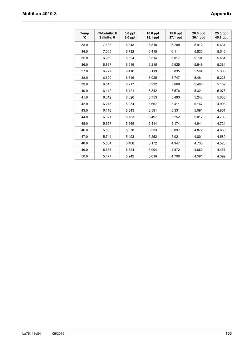
MultiLab 4010-3 Appendix
33.0 7.183 6.843 6.518 6.208 5.912 5.631
34.0 7.065 6.732 6.415 6.111 5.822 5.546
35.0 6.950 6.624 6.314 6.017 5.734 5.464
36.0 6.837 6.519 6.215 5.925 5.648 5.384
37.0 6.727 6.416 6.119 5.835 5.564 5.305
38.0 6.620 6.316 6.025 5.747 5.481 5.228
39.0 6.515 6.217 5.932 5.660 5.400 5.152
40.0 6.412 6.121 5.842 5.576 5.321 5.078
41.0 6.312 6.026 5.753 5.493 5.243 5.005
42.0 6.213 5.934 5.667 5.411 5.167 4.993
43.0 6.116 5.843 5.581 5.331 5.091 4.861
44.0 6.021 5.753 5.497 5.252 5.017 4.793
45.0 5.927 5.665 5.414 5.174 4.944 4.724
46.0 5.835 5.578 5.333 5.097 4.872 4.656
47.0 5.744 5.493 5.252 5.021 4.801 4.589
48.0 5.654 5.408 5.172 4.947 4.730 4.523
49.0 5.565 5.324 5.094 4.872 4.660 4.457
50.0 5.477 5.242 5.016 4.799 4.591 4.392
Temp °C
Chlorinity: 0Salinity: 0
5.0 ppt9.0 ppt
10.0 ppt18.1 ppt
15.0 ppt27.1 ppt
20.0 ppt36.1 ppt
25.0 ppt45.2 ppt
ba76143e04 09/2015 133

Appendix MultiLab 4010-3
19.2 DO% Calibration values
Pressure Altitude Calibration value
Inches Hg mm Hg kPa mbar Feet Meters % Saturation
30.22 767.6 102.3 1023 -276 -84 101
29.92 760 101.3 1013 0 0 100
29.62 752.4 100.3 1003 278 85 99
29.32 744.8 99.3 993 558 170 98
29.02 737.2 98.3 983 841 256 97
28.72 729.6 97.3 973 1126 343 96
28.43 722 96.3 963 1413 431 95
28.13 714.4 95.2 952 1703 519 94
27.83 706.8 94.2 942 1995 608 93
27.53 699.2 93.2 932 2290 698 92
27.23 691.6 92.2 922 2587 789 91
26.93 684 91.2 912 2887 880 90
26.63 676.4 90.2 902 3190 972 89
26.33 668.8 89.2 892 3496 1066 88
26.03 661.2 88.1 881 3804 1106 87
25.73 653.6 87.2 871 4115 1254 86
25.43 646 86.1 861 4430 1350 85
25.13 638.4 85.1 851 4747 1447 84
24.84 630.8 84.1 841 5067 1544 83
24.54 623.2 83.1 831 5391 1643 82
24.24 615.6 82.1 821 5717 1743 81
23.94 608.0 81.06 811 6047 1843 80
23.64 600.4 80.05 800 6381 1945 79
23.34 592.8 79.03 790 6717 2047 78
23.04 585.2 78.02 780 7058 2151 77
22.74 577.6 77.01 770 7401 2256 76
22.44 570.0 75.99 760 7749 2362 75
22.14 562.4 74.98 749 8100 2469 74
21.84 554.8 73.97 739 8455 2577 73
21.54 547.2 72.95 729 8815 2687 72
21.26 539.6 71.94 720 9178 2797 71
20.94 532 70.93 709 9545 2909 70
20.64 524 69.92 699 9917 3023 69
20.35 517 68.91 689 10293 3137 68
20.05 509 67.9 679 10673 3371 67
19.75 502 66.89 669 11058 3371 66
134 ba76143e04 09/2015

MultiLab 4010-3 Contact Information
20 Contact Information
20.1 Ordering & Technical Support
When placing an order please have the following information available:
20.2 Service Information
YSI has authorized service centers throughout the United States and Internationally. For the nearest service center information, please visit www.ysi.com and click ‘Support’ or contact YSI Technical Support directly at 800-897-4151.
When returning a product for service, include the Product Return form with cleaning certification. The form must be completely filled out for an YSI Service Center to accept the instrument for service. The Product Return form may be downloaded at www.ysi.com and clicking on the ‘Support‘ tab.
Telephone: (800) 897-4151(937) 767-7241Monday through Friday, 8:00 AM to 5:00 PM ET
Fax: (937) 767-1058
Email: [email protected]
Mail: YSI Incorporated1725 Brannum LaneYellow Springs, OH 45387USA
Internet: www.ysi.com
YSI account number (if available) Name and Phone NumberModel number or brief description Billing and shipping addressQuantity Purchase Order or Credit Card
135ba76143e04 09/2015
Contact Information MultiLab 4010-3
136 ba76143e04 09/2015


1) The tissue in plants that brings water upward from the roots;2) a leading global water technology company.
We're 12,500 people unified in a common purpose: creating innovative solutionsto meet our world's water needs. Developing new technologies that will improvethe way water is used, conserved, and re-used in the future is central to our work.We move, treat, analyze, and return water to the environment, and we help peopleuse water efficiently, in their homes, buildings, factories and farms. In more than150 countries, we have strong, long-standing relationships with customers whoknow us for our powerful combination of leading product brands and applicationsexpertise, backed by a legacy of innovation.
For more information on how Xylem can help you, go to www.xyleminc.com
Xylem |' m|zīlə
YSI1725 Brannum LaneYellow Springs, OH 45387Tel: +1 937-767-7241; 800-765-4974Fax: +1 937-767-1058Email: [email protected]: www.ysi.com
©Xylem Inc


