

See discussions, stats, and author profiles for this publication at: https://www.researchgate.net/publication/346923177
Multiple inheritance for a modular BIM
Article · May 2020
CITATIONS
0READS
6
6 authors, including:
Some of the authors of this publication are also working on these related projects:
Formal methods for NLP View project
Web of Things for smart building View project
Pierre Bourreau
Nobatek/INEF4
17 PUBLICATIONS 36 CITATIONS
SEE PROFILE
All content following this page was uploaded by Pierre Bourreau on 10 December 2020.
The user has requested enhancement of the downloaded file.
Multiple inheritance for a modular BIM
Pierre Bourreau1, Nathalie Charbel1, Jeroen Werbrouck2, Madhumitha Senthilvel3,
Pieter Pauwels4 and Jakob Beetz3
1 Nobatek/INEF4, 64600 Anglet,
{pbourreau,ncharbel}@nobatek.inef4.com 2 Ghent University,
3 RWTH Aachen
{senthilvel, j.beetz}@caad.arch.rwth-aachen.de 4 Eindhoven University of Technology, [email protected]
Résumé : L’IFC a été créé comme format ouvert standard pour l’interopérabilité des logiciels BIM. Son adoption est pourtant
rendue délicate par sa structuration monolithique, non-modulaire et néanmoins en constante croissance. Un des enjeux est donc de
permettre une meilleure maintenance de ce modèle tout en veillant à son évolution future, et à son adaptabilité à différents types
de projets, sur différents types d’ouvrages. Nous proposons une nouvelle approche pour la structuration de modèles IFC basée
essentiellement sur l’héritage multiple. Nous montrons comment cette architecture permet une modularisation complète d’un
modèle BIM ouvert selon trois couches principales : (i) le découpage du bâtiment en différentes vues ; (ii) la catégorisation des
éléments du bâtiment ; (iii) et la définition de propriétés pour ceux-ci. Nous comparons cette approche à différents travaux, et nous
illustrons notre propos au cas d’un IFC pour la rénovation.
Mots-clés : IFC, modularité, extensibilité, héritage multiple, patron de conception.
Abstract: The Industry Foundation Classes (IFC) was created as an open standard format to ensure interoperability between BIM
software. Yet, its monolithic, non-modular structure makes it difficult to implement, extend and use. The need for an architecture
that is easy to maintain, to extend, and to adapt to different types of projects and different types of buildings is becoming a challenge.
We propose a new architecture for IFC, mainly based on a simple principle: multiple inheritance. We show how this approach can
be used for a modular BIM, through the creation of modules in three different layers: (i) the view layer to identify elements in the
building; (ii) the product layer to categorize those elements; (iii) and the domain layer to attach properties to elements. We compare
our approach to existing and similar approaches , and we show how it can be used to build an IFC model for retrofitting.
Key-words: IFC, modularity, extensibility, multiple inheritance, design pattern.
1 Introduction
Building Information Modelling (BIM) is associated to the concept of a virtual model of a
building, that can be used during the overall building life cycle (i.e. programming, conception,
implementation, commissioning, exploitation and even demolition). A subsequent ambition of this
digital model is to contain enough information so that each actor can work on it, something
challenging considering the fragmentation of the Architecture, Engineering and Construction
(AEC) industry. Nowadays, many BIM software tools are being used in a competitive market. In
this context, interoperability issues were raised, back in the 1990s, which led to the definition of
an open exchange format by the sector: IFC (Industry Foundation Classes).
Since the initial works, IFC has evolved over different versions, making it a continuously
growing schema with properly released versions. Current discussions within buildingSMART, the
organization in charge of the IFC standard, consider extensions to describe not only buildings, but
also infrastructure, such as roads, railways or bridges. The growth of the model is not foreseen as
reaching an end. In contrast, the current latest IFC version (IFC4.2) is presented as a single schema
containing all the information: while different modules are conceptually present in the schema,

separating those seems far from trivial, with respect to the amount of inter-module dependencies
(Terkaj and Pauwels, 2017). In addition to its continuous growth, the need for modularity is also
relevant for the building equipment industry, in order to describe products in an IFC-compliant
way. For those, there is a need for classifying their products under the right IFC category, and also
to associate to their products the desired properties. In IFC, the properties associated to an element
are declared through property and quantity sets, as well as intermediary concepts enabling many-
to-many relations everywhere (IfcRelationship and subclasses), but this results in long-distance
access between a concept and its attributes. Finally, while IFC is the result of an international
standardization process, regulations, properties and nomenclatures can vary from one region to
another, and constraints from one project to another.
In this paper, a design pattern is proposed to build a modular and extensible IFC. Our proposal
is based on different principles, the main one being multiple inheritance/instantiation. Indeed, by
allowing a particular object to be an instance of different classes, we want to reflect its different
functionalities and roles in a building. In order to illustrate our proposal, we consider the use of
BIM for buildings’ retrofitting. In such contexts, some of the requirements are to model (i) the
state of the building (damage and deterioration) and (2) uncertainty: when characterizing the
existing building, tools and knowledge may be inaccurate (Volk et al, 2014). Such information
cannot be straightforwardly modelled in IFC and we show how our proposal can provide answers
to these issues. Additionally, we also discuss the compactness of the final model, as well as the
complexity for querying it.
The rest of the paper is structured as follows: in section 2, we propose a diagnosis on IFC;
section 3 contains a state of the art of initiatives that have been taken to simplify IFC; in section 4,
we detail the key concepts for our proposal of a modular IFC, and a draft model; in section 5, we
compare our proposal with the existing ones; finally, section 6 gives some conclusion and
perspective for this work.
2 IFC – a detailed monolithic format
IFC is the result of a long-standing work between BIM software vendors and practitioners, to
define a common ground, understandable across different countries, and that entails minimal sets
of concepts that are relevant to different domain experts in the construction sector (architectural,
structural, thermal, environmental,...). But agreeing on a minimal set of information seems
complex, resulting in a constantly-growing schema, as summarized in Table 1.
TABLE 1 - Evaluation of the historical growth of the IFC schema.
IFC Version Date of publication File Size (EXP) #Types #Entities
IFC 2x 2000-10 180 kB 228 370
IFC2x-ADD1 2001-10 188 kB 228 370
IFC2x2-Final 2003-05 238 kB 312 623
IFC2x2-ADD1 2004-07 188 kB 327 370
IFC2x3 2005-12 261 kB 397 653
IFC2x3-TC1 2007-07 261 kB 327 653
IFC4 2013-02 379 kB 391 766
IFC4-ADD1 2015-06 361 kB 398 768
IFC4-ADD2 2016-07 364 kB 397 776
IFC4-ADD2-TC1 2017-10 364 kB 397 776
IFC4x1 2018-06 371 kB 400 801
IFC4x2 2019-04 378 kB 407 816

The IFC schema is structured in four different layers1, each containing a number ofmodules: (i)
the resource layer contains basic elements that can be reused at each other level (e.g. currency,
occupant types, units...); (ii) the core layer is made of the most basic elements that are used to
describe a building, a product, a process or a constraint; (iii) the interoperability layer describes
generic entities (e.g. a wall, a window, an energy conversion device); and (iv) the domain layer
contains specializations of the elements in the interoperability layer for specific domains
(electrical, plumbing, HVAC, ...). While the intention of modularizing the schema was originally
there, the IFC schema has evolved into a unique EXPRESS schema, with multiple dependencies
between concepts and modules in opposite directions (cyclic graph). Working with the schema
and identifying relevant parts is therefore a complex task. Additionally, standardizing new growing
versions of the schema is also a complex task, as the organization body needs to ensure new
concepts are not already modelled.
While IFC results from a great effort to unify concepts in a fragmented industry such as the
AEC one, it still suffers from various lacks. One of them is the need to specialize some concepts
or properties for a particular project need; in particular, the properties of importance attached to
building elements can vary depending on the geographical region. In the same way, product
vendors may need or want to extend their own products with additional specific properties. While
IFC offers extension mechanisms through the definition of additional property sets for particular
objects, it offers too much freedom leading to the generation of IFC STEP files that are not aligned
with the standard, and existing properties in the original schema can thus be duplicated under new
property sets. The extension mechanism native to the EXPRESS language (IMPORT SCHEMA)
is not supported or used. Another complexity resides in providing different IFCs (or better said
different views of a building model) to the different building experts; indeed, a thermal engineer
does not need the same information as a plumber for instance. While a categorization of concepts
and properties is proposed in the domain layer, it does not deal with inter-domain information (i.e.
shared by different domain experts).
From a more technical point of view, the IFC schema, as already mentioned, is a single
EXPRESS file, and considering its growing behaviour, and its existing structure, it seems more
intuitive to have separated files for each module. Additionally, the use of Property Sets is
debatable, as it inserts intermediate steps (the property set, the property itself, and the many-to-
many relationship steps in between) between a concept and a property value. In comparison, in the
object-programming paradigm, classes tend to provide direct access to their attributes. In the IFC
schema, however, concepts also have attributes attached, and property sets seems to be used as
both an extension mechanism, and a way of sharing properties across different concepts. Finally,
the IFC schema structure is a single inheritance tree: a concept can have only a single parent
concept. Any IFC instance data also has a single IFC classification. And many relations have
redundant inverse relations pointing up and down the tree. Considering the size of the schema, the
need to share information between different concepts, as well as the need to offer different views
to different actors of the sector, these technical points, and particularly the single inheritance and
classification, can also be seen as a weaknesses, which is at the core of this article.
Modularizing IFC is key for the future and broader usability of the standard, and
buildingSMART is considering this task, as described by van Berlo (2019), for whom key design
patterns and efforts for new IFC versions should be (i) to clean up the resource layer, so as to only
insert the most widely used concepts in the layer; (ii) in a similar way, to re-structure the core layer
of IFC so that it is only made of the most common concepts; (iii) to better integrate product
definition and the efforts from the bSDD (buildingSMART Data Dictionary), through the
possibility to specialize properties of building elements in a hierarchical way, from international
to regional agreements, to project specific needs (Fig. 1). The main guideline is therefore to focus
on standardizing the minimum of information that is shared in the AEC industry and to implement
1 https://standards.buildingsmart.org/IFC/RELEASE/IFC4/ADD2_TC1/HTML/link/introduction.htm

extension layers to handle specificities. This would also force software vendors to implement this
minimal set of information in a correct way, to ease the interoperability between software, which
is the initial goal of IFC, a goal not yet reached.
FIGure 1 – Proposal draft architecture of a modular IFC3 by buildingSMART International.
3 Intents for a simplified IFC
Different works to offering BIM some modularity, additional extension mechanisms, and
simplification exist. In this section, the main initiatives to this direction are explained.
3.1 IfcOWL
The ifcOWL (LDWG, 2007 and Beetz et al, 2009) is the representation of the IFC standard
(buildingSMART, 2000) in the Web Ontology Language (OWL), leading to an OWL ontology
directly converted from the EXPRESS schema. The main goal is to migrate into Semantic Web
technologies to support data interoperability, flexibility and extensibility within information
system applications in the construction industry. In this direction, there have been several
approaches for the EXPRESS-to-OWL conversion, such as (Agostinho et al., 2007), (Barbau et
al., 2012), (Schevers & Drogemuller, 2005) (Terkaj et al., 2012). Among all approaches, (Pauwels
& Terkaj, 2016) propose a recommendable and usable ifcOWL ontology. It is semantically closer
to the original IFC Schema standard in comparison to alternative approaches. However, since the
ontology encapsulates being a direct mapping of the IFC schema, it does not solve the main
problems. IfcOWL, just like its EXPRESS and XSD equivalents, is monolithic, non-modular, and
supporting mainly a single inheritance and classification tree by the presence of the many
constraints, and the interconnecting relations and inverses.
3.2 SimpleBIM
In order to overcome the complexity of building models represented in ifcOWL graphs,
Pauwels & Roxin (2016) propose an approach towards simplification of such graphs using
semantic web technologies including query and rule languages (e.g., SPARQL and SWRL). The
3 Source : https://blog.buildingsmart.org/blog/the-curious-case-of-the-mvd
proposed simplification process was called SimpleBIM4 and consists of 4 main parts: (i) removing
geometric and representation data as the RDF graph data model is unfit for storing such data (the
required linked list design pattern does not fit efficiently), (ii) unwrapping all data types, so that
class instances are directly related to data properties, (iii) rewriting properties and removing a
considerable number of intermediate steps between class instances and their property values (e.g.:
xsd:string instead of ifc:IfcLabel ifc:hasValue xsd:string), and (iv) replacing relational instances
(i.e., instances of ‘IfcRelationship’) with direct object properties between class instances (many-
to-many relations are natively supported in the RDF data model, without requiring intermediate
concepts). The last two rules are inspired by the ifcWoD simplification approach (Mendes et al.,
2015). This initiative does not work as a refactoring of the schema, but as a refactoring of the
instances (i.e. a specific building model) and the main goal seems to prove how such rewritings
can lead to more efficient data handling and querying, without looking at the modularity of the
schema or instances.
3.3 Linked Building Data (LBD)
The work on SimpleBIM was one of the inspirations behind the set up of the Linked Building
Data (LBD) initiative in the World Wide Web Consortium (W3C)5. Where the SimpleBIM and
IfcWoD approaches lacked ontologies, a main target was to create OWL ontologies that allow a
modular and simplified (RDF native) representation of building data. This has led to the following
ontologies based on community work.
3.3.1 BOT
The development of distributed ontologies has several advantages over a one-size fits all, such
as interoperability and simple reuse. In this direction, the Building Topology Ontology (BOT)
(Rasmussen et al., 2017) is introduced as a modular ontology covering core concepts of the
building and three methods for extending it with domain-specific ontologies (such as ontologies
modelling information related to geographical location, sensor data, domotics, and construction
data). This reduces redundancies caused by overlapping data found in these ontologies, which is
currently violating the W3C best practice rules. Linking BOT to other ontologies can be done in
several ways: (i) extending the core classes with subclasses of more specialized ontologies, (ii)
defining equivalent classes, and (iii) establishing typed links between instances (Schneider et al,
2018). Based on these linking methods, efforts have been done to align BOT with BRICK (Balaji
et al., 2016), ifcOWL (Pauwels & Terkaj, 2016), DERIRoom (Cyganiak, 2012) and DogOnt
(Bonino & Corno, 2008) ontologies. Along the same lines, we intend to reuse BOT ontology and
link it to other modular ontologies describing elements and domains involved in a renovation
scenario such as building elements, HVAC elements, plumbing elements, etc. Based on
requirements mentioned in section 1, we believe that is better done using the third linking method
(i.e., on the instances level).
3.5 PRODUCT
3.3.2 BPO
The Building Product Ontology (BPO) (Wagner & Rüppel, 2019) is used to describe
individually manufactured building products as the assembly of their constituents, without setting
a maximum breakdown level. In this way, individual components from different manufacturers
can be assembled into one building product which can be useful to describe complex systems such
as solar panel integrated in a façade. The ontology consists of (i) classes (‘Component’, ‘Product’,
4 NOT related to the simpleBIM application (http://www.datacubist.com/)! 5 http://w3.org/community/lbd/

‘Element’, and ‘Assembly’) and relations (‘Consists of’ and ‘Is part of’) modelling assembly
structures, (ii) relations between components (‘Has outgoing connection’, ‘Connects input of’ and
‘Is connected with’), and (iii) classes and relations describing attributes attached to the product
description. BPO is aligned to well-known upper-level ontologies, such as schema.org6
and SEAS7, and brings product decomposition functionalities in a modular fashion in combination
with the BOT ontology.
3.3.3 OPM
The Ontology for Property Management (OPM) (Rasmussen et al., 2018) is an ontology for
describing properties that are subject to changes as the building design evolves over time, or to
associate metadata to them (provenance, reliability…). The relevance of the latter in renovation
scenarios was already discussed. Three levels of data modelling extensions are presented and
discussed, for different scenarios. OPM allows keeping track of deleted properties so they can be
restored if needed, and is also being considered at the CEN TC442 (BIM standardization in
Europe) as a possible future standard to handle additional properties in BIM through Linked Data.
3.4 Building Element and Distribution Element ontologies
Pauwels proposes two ontologies as extraction of the “BuildingElement” and
“DistributionElement” sub-trees in the IFC schema: the Building Element8 and Distribution
Element9 ontologies respectively, both regarded as taxonomies: attributes and relations are kept
out of these ontologies as user requirements may differ from one domain to another. The intention
is to simply allow the categorization of specific products in an IFC compliant way. The. concepts
of the 2 ontologies are linked to classes in ifcOWL and the buildingSMART Data Dictionary
(bSDD) (seeAlso links) for documentation purposes. However, changes are made w.r.t. the IFC
schema, such as “Enumeration Types” in the IFC specifications (or predefined type instances in
the ifcOWL) are directly included as subclasses (e.g., CO2Sensor). Moreover, “Undefined Type”
or “User-defined Type” mentions in the IFC specifications are excluded. OWL can be used by
users to define their own types if needed, and anything that is not defined in OWL, is unknown by
default in the Open World Assumption of OWL, so there is no need for ‘User-defined’ and
‘Undefined’ references, The use of such ontologies reflects a maximum degree of modularity and
flexibility while keeping a close relation with the standardization effort resulting in the IFC
standard. Many of the Object Type Libraries (OTLs) used in construction practice could easily
take the same approach.
3.5 DOT
The Damage Ontology Topology (DOT) (Hamdan et al, 2019) allows the definition of damage
representations and their relations with other damages and affected construction components. It
applies to any construction type including buildings and bridges. It comprises 3 main entities:
dot:DamageArea which can be made of the aggregation of several elementary damage elements,
i.e., dot:DamageElement and can be regrouped in damage patterns defined as dot:DamagePattern.
A cause can be given to certain damage by using the dot:hasCausation relation. The range of this
relation is intentionally left open for interpretation. Current extensions are being developed in
context of the German WiSiB project, among which are the Uncertain Damage Ontology (UDO)
(Hamdan, 2019) and the Concrete Damage Ontology (CDO) (Hamdan & Bonduel, 2019).
6 https://schema.org/ 7 https://ci.mines-stetienne.fr/seas/ 8 https://pi.pauwel.be/voc/buildingelement/ 9 https://pi.pauwel.be/voc/distributionelement/

3.6 Recap
Table 2 summarizes the schema of ontologies discussed above in terms of metrics (i.e., number
of classes, relations or object properties, attributes or data properties, and individuals) when
available, their scope and examples of alignment that have been done so far to link them together.
The lack of modularity and complexity of the IFC schema appears clearly through the number of
attributes and relations. Even though the BuildingElement and DistributionElement ontologies
have a considerable number of classes, they lack any relation, thus removing any kind of
complexity besides the classification tree structure (taxonomy). In the context of the BIM4Ren
project and more generally in order to provide a modular IFC version, it seems that smaller
modules, dedicated to modelling specific building domains should be designed or reused from the
existing ones. The next key step would then be on linking the different modules all together to
deliver a complete building model to end-users. Finally, one would remark that geometry is not
addressed in the modules below (apart from ifcOWL). That is mainly due to the same reason,
namely that the RDF data model is an inefficient storage mechanisms for linked lists, and therefore
also for 3D geometry. Modelling, handling and storing geometry information is a topic in itself,
that requires dedicated efforts (e.g. Wagner et al, 2019; Bonduel et al, 2019).
TABLE 2 - Recap on BIM-based ontologies and related modular ontologies.
Ontology Metrics Scope Alignment ifcOWL (Pauwels &
Terkaj, 2016) 1230 classes
1578 relations 5 attributes
1627 Individuals
IFC Schema BOT Building Element
Distribution Element
SimpleBIM (Pauwels
& Roxin, 2016) Not available Simplified IFC Schema
(without geometry) Not available
BOT (Rasmussen et al.,
2017)
7 classes 14 relations 1 attribute
0 Individual
Building topology BRICK DERIRoom
DogOnt ifcOWL
OPM (Rasmussen et al.,
2018)
7 classes 5 relations 2 attributes 0 individual
Properties and their states BOT SEAS
BPO (Wagner et al., 2019)
14 classes 19 relations 5 attributes 0 individual
Manufactured building
products or instances of those
product
Schema.org SEAS
Building Element
(Pauwels, 2018) 182 classes 0 relation 0 attribute
0 individual
Subtree of IfcBuildingElement
in the IFC Schema PRODUCT
bSDD ifcOWL
Distribution Element
(Pauwels, 2018) 480 classes 0 relation 0 attribute
0 individual
Subtree of
IfcDistributionElement in the
IFC Schema
PRODUCT bSDD
ifcOWL
DOT (Hamdan & Bonduel,
2019b)
12 classes 13 relations 2 attributes 0 individual
Damages related to a
construction type (Buildings,
bridges)
Concrete Damage Ontology Uncertain Damage Ontology
4 Modular IFC - a design pattern proposal
Our proposal for a modular and extensible IFC is based on a four layer structure (Fig. 2): (i) the
resource layer, as for IFC, is still the place to share information that can be used as properties or
quantities in the model, but all properties need to be encapsulated in a concept containing ‘Value’
and ‘Unit’ attributes at least; (ii) the view layer plays the role of the core layer; it is made of
different models, used for different views on the building, and relation between building
components: the most fundamental and mandatory module is a model to locate elements in the

building (similar to BOT); other models can be part of this layer to describe elements in a MEP
system for instance; (iii) the product layer, similar to the layer in the architecture proposed by van
Berlo (2019), and basically a minimal set of informed hierarchies of products classified by
categories; (iv) a set of models made of abstract concepts according to different domains, such as
‘Electricity’, ‘Carbon Impact’, ‘Thermal’. Our approach is then based on full independence
between all these models: no hard-coded dependence should exist between them; instead linking
the different modules is performed when instantiating objects, through multiple binding (similar
to multiple inheritance and classification in the object-oriented paradigm), to reflect the multiple
properties and roles of elements of a building.
FIGURE 2 – Schema for a modular architecture IFC based on multiple inheritance.
4.1 Description of the architecture
First of all, the resource layer is a refactoring of the identically named layer in the IFC schema;
indeed, for the sake of extensibility, we consider that a value needs to be described under an
encapsulated data type, made of at least two attributes: ‘Value’ and ‘Unit’. This approach is really
similar to level 2 modelling of properties in OPM; and different from the SimpleBIM approach.
This could be extended for the need of any project. For instance, in the case of using BIM in a
renovation project, one of the key issues is to deal with data uncertainty, which can be related to
non-available materials (for instance, the layer composition of a wall, dimensions of these layers
and type of materials used) or even about the tools used for scanning the geometry of the building,
or the approximation made when modelling it. A recommendation with the proposed design
pattern is to constantly use the same data type encapsulation for all the data in the project for
coherence purpose, and in order to avoid to deal with too many specific cases when, for instance,
parsing the model. In the case of a renovation project, we would recommend using the
‘UncertainDatatype’ in Figure 3 as the base type for all subsequent data used; this could involve
specifying a default value of 1 to the uncertainty indicator. Additionally, we recommend the use
of the QUDT nomenclature, by (i) removing all the concepts unnecessary to the building context
and (ii) extend it to include missing concepts required. This is currently being worked in the BIM
standardization group within the European Committee for Standardization (CEN).

FIGURE 3 – Example of multiple inheritance: extending datatypes.
In the view layer, we propose to use or develop different ontologies that are used to
contextualize elements according to different needs or usages. A first model called the
‘Localization View’, similar to the spatial-related elements in the ‘IfcProductExtension’ of the
Core Layer of the IFC Schema, is used to describe the spatial structure of the buildings, and to
enable the localization of additional elements. This model can be extracted from the IFC Schema
or the BOT ontology, both of them respecting the hierarchical structure of ‘Sites’, ‘Buildings’,
‘Storeys’ and ‘Spaces’. Other models should be developed according to the different usages. For
instance, a MEP (Mechanical, Electrical and Plumbing) view should be developed to identify
products’ roles in the distribution of gas, electricity or water in a building. Such a model can be
built based on the generic concepts already present in the ‘IfcSharedBuildingElements’ module of
the IFC schema. Regarding the design pattern to apply, and in order to preserve independence
between the different modules, we propose to have an abstract class in each view model, that can
be instantiated by external objects; this is the pattern applied in the BOT ontology through the
‘bot:Element’ class, to attach a localization to an external product.
The Product layer is made of categories of generic products, with a minimal set of attributes
attached to them. The goal of this layer, just as in Figure 1, is to have a common standard list of
products that must be re-used and further specialized by product manufacturers. Again, the
standardization efforts can be re-used to define the content of this layer, in the fashion of the
taxonomies in section 3.7, or by extending those taxonomies with the attributes associated to the
different concepts of IFC. As an example, Figure 4 illustrates how an ‘IfcWindow’ would be
translated from the IFC Schema into a UML class, by mapping attributes in the schema to attributes
in a class. Nevertheless, and similarly to what is done in SimpleBIM, we simplify the usage of
Enum Types, so that values in ‘IfcWindowTypeEnum’ should be mapped to sub-classes of
‘IfcWindow’, similarly to the simpleBIM approach. Similarly,
‘IfcWindowTypePartitioningEnum’ should be mapped to the ‘IfcWindowPartitioning’ class with
specific sub-classes or instances (and the ‘UserDefinedPartitioningType’ would be implemented
by defining a new instance or sub-class of the WindowPartitioning class).

FIGURE 4 – Mapping of an IFC concept and its attributes into a UML class diagram, through the
example of an IfcWindow.
The final top layer is made of concepts related to the domain in which the building products
reside (Thermal, Electric, Acoustic, Environmental). This particularly relates to the PSets in IFC.
Let us consider the definition of an IfcBoiler in the IFC Schema as an example; different PSets are
attached to it: (i) PSet_BoilerTypeCommon, including properties such as the storage capacity,
nominal energy consumption; (ii) PSet_SoundGeneration, including a table of frequencies
generated; (iii) PSet_ElectricalDeviceCommon, including properties related to the electrical
consumption of the device; and (iv) PSet_EnvironmentalImpactIndicators and
PSet_EnvironmentalImpactValues, associated to the waste generated, renewable energy
consumption, or other factors considered in life cycle analysis10. Those PSets can be reformulated
as aspects of the boiler, which can either be seen as a thermal system (i) an acoustic generator (ii),
an electrical device (iii), or a product having an environmental impact (iv). Such reformulation
leads to defining different domains (thermal, acoustic, electric and environmental) and a particular
boiler becomes an instance of a specific class in each of these categories (see Figure 5).
10 Some other PSets are used, not considered for the sake of concision.

FIGURE 5 – Multiple instantiation to model an electric boiler.
4.2 A combined data model
The proposed approach is based on a full independence between the different modules: there
is no hard link (i.e. links between the different classes in a module - in a UML or Object-Oriented
paradigm; links between concepts in the TBox in the web semantic paradigm) between modules
of different layers, or modules of the same layer, apart from the resource layer that should be used
for any data type associated to an attribute. Instead, linking the different classes is achieved when
instantiating a specific object: as an example, we saw how a specific boiler can instantiate different
classes to describe different aspects; this boiler is also an instance of the ‘Boiler’ class in the
Product layer; and an instance of ‘BuildingElement’ in the Localization View, and of ‘System
Element’ in the MEP View.
It is crucially important to stress that this approach could a priori allow incoherent instantiation
of objects (for instance a window as a gas consumer), and the semantic coherence of the model is
the entire responsibility of the specific building or product designers and engineers (human in the
loop). In order to solve this issue, one could use formal ontologies that describe specific inter-
modules linking, so that the coherence of the model remains easily maintainable; for instance, a
‘BoilerAspects’ ontology would define the restrictions between the Boiler class in the Product
layer, and the classes of the domain layer. One would note that a similar freedom exists in IFC as
any kind of PSet can be attached to a class.
While the design pattern we suggest is focused on modularity, it is also extensible in various
ways. First of all, new modules can be added if required for a specific project; this can be the case
for specific domain properties. Such new modules can be independent from the existing ones, or
can extend the latter. For instance, in the BIM4Ren project, we consider the BOT ontology as the
basis for the localization view, but we extend it so as to integrate concepts from Omniclass about
the typology of the different spaces in a residence, or of different kinds of residential buildings
(see Figure 6). A similar approach may be relevant to deal with refinements of properties as
described in van Berlo (2019), from international standards to project specific: the set of standard
properties attached to a product A may be encapsulated under n concepts 𝐴1, ..., 𝐴𝑛 in the domain
layer; those might be extended into concepts 𝐴1′ , ..., 𝐴𝑛
′ to integrate local or project specific
properties. Such an approach would again purely rely on the inheritance mechanism, and can then
be replicated to different formalisms. An additional question related to the extension of the model
is related to composed product definition. For instance, an integrated solar panel in a façade is
made of different products. The use and integration of BPO or a similar approach should be further

studied but it intuitively seems that it can be integrated into the proposed design pattern: a given
product in the product layer can be instantiated as either an assembly (i.e. a composed product) or
an element (i.e. a part of the composed product).
FIGURE 6 – Graph representation for the BOT extension to model buildings topologies and functional
spatial structures.
This modular approach can then be further explored for the proposal of a new standard IFC
architecture, but the question of the minimal set of concepts and properties that could be used as a
standard remains. The current IFC version should obviously be a starting point, although many of
its concepts are arguably suited to be included in the standard. For instance, a monitoring project
could be run with information restricted to the localization view, product layer, and with additional
information on sensors, meters and actuators (i.e. the IFC4 Control Domain) (see for instance
Chbeir et al. 2018). Through such a modular approach, it should be possible to define different
standard IFCs for different uses at different steps of the building life cycle, with a shared core
structure.
5 Comparison
In this section, we compare our approach with some of the other initiatives presented in Section
3, and try to compare our approach with current IFC models.
5.1 Modularity and extensibility
First of all, and as already commented in previous sections of the current article, our approach
relies on and can integrate different works provided by the community: BOT can be taken as the
core localization view; the building element and distribution element taxonomies (fully extracted
from the IFC model) can form the kernel of concepts for the product layer; and the use of the
Building Product ontology was discussed to describe complex products. Our approach is therefore
not directly comparable with those, as they address specific parts of a building model, but is rather
a proposal for integrating those, and building new ones.
The simpleBIM initiative is closer to what we propose, although no straightforward comparison
is possible, because simpleBIM results from a fully automatic refactoring (without ontology) of
ifcOWL models, while our approach is not. Moreover, the goal of simpleBIM seems to be a
simplification of ifcOWL instantiations for a better response time on queries, while our approach
focuses on the modularization of the IFC model. Nevertheless, we can already identify some
similarities and differences between our approach and the simpleBIM approach. First of all, data

types are unwrapped in simpleBIM while we propose an opposite approach, through data
encapsulation. The simpleBIM approach will shorten the verbosity of the model, and shorten the
path between a concept and its numerical attributes; our approach is focused on enabling model
extension, even at the data type level. We don’t go as far as IFC, however, and do not redefine
basic data types such as strings into IfcText, IfcLabel, and similar (also for other data types).
Secondly, PSets are removed in both approaches: in simpleBIM, properties in PSets are directly
rewritten as attributes while we propose to have PSets refactored as specific classes. At the instance
level, both approaches seem to offer similar results: an instance I of a concept C would have a
direct relation to its properties, shortening the path to data access and therefore simplifying and
speeding up querying time response on a specific building model; in our proposal, we show how
this can be enabled through multiple inheritance and modularization mechanisms at the model
level, while simpleBIM proposes a refactoring at the instance level. Other simplifications are
proposed in simpleBIM: ‘IfcRelationship’ classes are replaced with attributes/relations. This is not
tackled in the current proposition as it needs to be addressed within each module. Another key
simplification is the removal of the geometric information which results in a dramatic reduction
of the size of the model. The question of the modelling of the geometry remains as it cannot be
simply removed, yet we refer to the approach suggested in the W3C LBD CG as the most viable
alternative. A ‘geometric’ module could be designed in our approach, associating attributes to
accurately define the shape of the building and its components, and the integration of a
‘GeometricElement’ that would be instantiated by each element geometrically described (Wagner,
2019; Bonduel, 2019).
TABLE 3 - Description of the BIM4Ren data model
Layer Module Description Comment Resource Layer property.ttl 243 classes
65 relations
42 attributes
1024 individuals
Extension of the QUDT ontology, to model
numerical quantities and units. Additional use of
‘Uncertainty’.
actor.ttl 7 classes
2 relations
1 attribute
6 individuals
Description of the different individuals that can be
associated to a renovation project (Building
manager, owner, occupant...)
View Layer buildings.ttl 32 classes
19 relations
19 attributes
6 individuals
Extension of the BOT ontology to integrate
Omniclass specific concepts such as room usage
(‘Kitchen’, ‘Sleeping Room’...), buildings
categories (‘Dormitory’, ‘Single Family house’...)
to describe residential buildings systems.ttl 11 classes
4 relations
0 attributes
12 individuals
Generic description of systems as networks, made
of control, storage, terminal and transport elements.
To be used to describe HVAC or Plumbing
structures for instance. dot.ttl 13 classes
13 relations
3 attributes
1 individual
The damage topology ontology.
intervention.ttl 6 classes
4 relations
2 attributes
0 individuals
Attach historical intervention listing to elements
Product Layer
buildingElement.ttl 182 classes 0 relation 0 attribute
0 individual
Subtree of IfcBuildingElement in the IFC Schema -
extracted from (Pauwels, 2018)
distributionElement.ttl 480 classes 0 relation 0 attribute
0 individual
Subtree of IfcDistributionElement in the IFC
Schema - extracted from (Pauwels, 2018)
Domain Layer
thermal.ttl 2 classes
8 relations
0 attributes
0 individuals
Categorization of elements as ‘HeatProducer’ or
‘HeatTransferElements’, and related thermal
properties
electrical.ttl 2 classes
2 relations
0 attributes
0 individuals
Categorization of elements as ‘ElectricalProducer’
or ‘ElectricalConsumer’, and power produced in
entry or output.
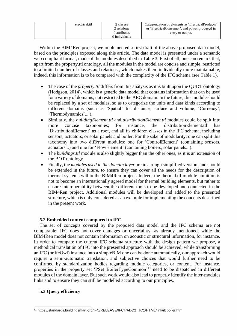
Within the BIM4Ren project, we implemented a first draft of the above proposed data model,
based on the principles exposed along this article. The data model is presented under a semantic
web compliant format, made of the modules described in Table 3. First of all, one can remark that,
apart from the property.ttl ontology, all the modules in the model are concise and simple, restricted
to a limited number of classes and relations , which makes them individually more maintainable;
indeed, this information is to be compared with the complexity of the IFC schema (see Table 1).
• The case of the property.ttl differs from this analysis as it is built upon the QUDT ontology
(Hodgson, 2014), which is a generic data model that contains information that can be used
for a variety of domains, not restricted to the AEC domain. In the future, this module should
be replaced by a set of modules, so as to categorize the units and data kinds according to
different domains (such as ‘Spatial’ for distance, surface and volume, ‘Currency’,
‘Thermodynamics’....).
• Similarly, the buildingElement.ttl and distributionElement.ttl modules could be split into
more concise taxonomies; for instance, the distributionElement.ttl has
‘DistributionElement’ as a root, and all its children classes in the IFC schema, including
sensors, actuators, or solar panels and boiler. For the sake of modularity, one can split this
taxonomy into two different modules: one for ‘ControlElement’ (containing sensors,
actuators...) and one for ‘FlowElement’ (containing boilers, solar panels...).
• The buildings.ttl module is also slightly bigger than the other ones, as it is an extension of
the BOT ontology.
• Finally, the modules used in the domain layer are in a rough simplified version, and should
be extended in the future, to ensure they can cover all the needs for the description of
thermal systems within the BIM4Ren project. Indeed, the thermal.ttl module ambition is
not to become an internationally agreed model for thermal building elements, but rather to
ensure interoperability between the different tools to be developed and connected in the
BIM4Ren project. Additional modules will be developed and added to the presented
structure, which is only considered as an example for implementing the concepts described
in the present work.
5.2 Embedded content compared to IFC
The set of concepts covered by the proposed data model and the IFC schema are not
comparable: IFC does not cover damages or uncertainty, as already mentioned, while the
BIM4Ren model does not contain information on acoustic or structural information, for instance.
In order to compare the current IFC schema structure with the design pattern we propose, a
methodical translation of IFC into the presented approach should be achieved; while transforming
an IFC (or ifcOwl) instance into a simpleBIM one can be done automatically, our approach would
require a semi-automatic translation, and subjective choices that would further need to be
confirmed by standardization bodies regarding module categories, or content. For instance,
properties in the property set ‘PSet_BoilerTypeCommon’11 need to be dispatched in different
modules of the domain layer. But such work would also lead to properly identify the inter-modules
links and to ensure they can still be modelled according to our principles.
5.3 Query efficiency
11 https://standards.buildingsmart.org/IFC/RELEASE/IFC4/ADD2_TC1/HTML/link/ifcboiler.htm

Finally, the architecture we propose also ensures some additional efficiency for some data
queries, in particular, for those specific to certain domains. As an example, let us consider IFC and
the BIM4Ren data model, and a query to retrieve the U-values associated to all windows of a
building. We consider both data models expressed in a semantic web-compliant format, so as to
formalize the query in a comparable way, in the SPARQL syntax. The two queries are presented
in Figure 6. It appears clearly that the query in the modular approach is less verbose, and requires
less sub-queries and graph traversals than in the IFC schema. This should result in a more efficient
time response, and an easier implementation of data access implementation for software vendors.
SELECT ?window ?u_value WHERE { ?window a ifc:IfcWindow. ?rel_def_prop
ifc:relatedObjects ?window; a ifc:IfcRelDefinesByProperties;
ifc:relatingPropertyDefinition
?prop_set. ?prop_set rdf:type
ifc:IfcPropertySet; ifc:hasProperties ?prop;
a ifc:IfcPropertySingleValue; ifc:name "Thermal Transmittance"; ifc:nominalValue ?u_value.
?u_value a
ifc:IfcThermalTransmittanceMeasure. }
SELECT ?window ?u_value WHERE { ?window a ifc:IfcWindow;
a thermal:HeatTransferElement;
thermal:thermalTransmittance
?u_qudt.
?u_qudt qudt:value ?u_value. }
FIGURE 6 – Query comparisons in ifcOWL and the BIM4Ren data model – SPARQL queries to obtain
all windows and their U-values
6 Conclusion and future works
IFC is the result of a collaborative effort from major representatives of the building value chain,
from software vendors to architects, engineers, housing companies and much more. The current
definition and open status of the IFC schema is of high value for the sector, but its constant growth,
and the difficulty to produce a world-wide adopted standard in a domain in which regulations and
conditions may dramatically vary, are appealing for more modularity. In this paper, we propose a
methodology to build up a modular IFC, based on a simple pattern: the use of multiple inheritance
(or multiple instantiations). We show that a fully modular IFC can be achieved through this
approach, meaning that every module is fully independent, does not require other modules.
The counterpart of this approach is that the coherence of a building model is delegated to the
person or process in charge of the instantiated schema. Our approach is compared to some
initiatives that can either be integrated into our approach (i.e. data model dedicated to the
modelling of part of the information contained in the IFC schema), or can be similar in some
respect (i.e. simpleBIM for efficient queries). In order to consolidate the presented approach, a
methodical transformation of the IFC schema should be done, so as to ensure that all standardized
information can still be modelled through this approach.
Finally, the modelling of the geometric data was intentionally not included in our study, which
essentially focuses on the semantic information. Geometric information forms a big part of the
data within any IFC building models, and dealing with it efficiently potentially require specific
technical stacks, like binary data storage or GeoSPARQL (O’Donovan et al, 2019). While different
technologies will be tested in the BIM4Ren project, the next IFC versions could focus on providing
a technology-independent way of linking the semantic model with a geometry-dedicated
modelling and storage solution.

Acknowledgements
The BIM4Ren project has received funding from the European Union’s Horizon H2020
research and innovation programme under grant agreement No 820773.
References
Agostinho et al. (2007). EXPRESS to OWL morphism: making possible to enrich ISO10303 Modules. Dans Complex
Systems Concurrent Engineering (pp. 391-402). Springer. Balaji et al. (2016). Brick: Towards a unified metadata schema for buildings. Proceedings of the 3rd ACM
International Conference on Systems for Energy-Efficient Built Environments, 41--50. Barbau et al. (2012). OntoSTEP: Enriching product model data using ontologies. Computer-Aided Design, 44, 575-
590.
Beetz et al. (2009). A case of transforming EXPRESS schemas into ontologies. Artificial Intelligence for Engineering
Designe, Analysis and Manufacturing 23 (1) 89–101. Bonduel, M., Wagner, A., Pauwels, P., Vergauwen, M., & Klein, R. (2019) Including widespread geometry formats
in semantic graphs using RDF literals. Proceedings of the 2019 European Conference for Computing in
Construction (EC3). p.341-350
Bonino, D., & Corno, F. (2008). Dogont-ontology modeling for intelligent domotic environments. (Springer, Éd.)
International Semantic Web Conference, 790--803. buildingSMART (2000). Industry Foundation Classes (IFC) Releases. Available at
https://technical.buildingsmart.org/standards/ifc/ifc-schema-specifications/
Chbeir et al (2018). OntoH2G: A Semantic Model to Represent Building Infrastructure and Occupant Interactions.
Dans International Conference on Sustainability in Energy and Buildings 2018 (Springer Eds.), 148--158. Cyganiak, R. (2012). Buildings and rooms vocabulary. Available at http://vocab.deri.ie/rooms
Hamdan, A.-H. (2019). Uncertain Damage Ontology. Available at https://wisib.de/ontologie/damage/udo/ Hamdan, A.-H., & Bonduel, M. (2019a). Concrete Damage Ontology. Available at
https://wisib.de/ontologie/damage/cdo/ Hamdan et al. (2019). An ontological model for the representation of damage to constructions. Proceedings of the 7th
Linked Data in Architecture and Engineering for Construction Workshop. Available at
https://alhakam.github.io/dot/ Hogson et al (2014). QUDT-quantities, units, dimensions and data types ontologies, Available at http://qudt. org
March, 2014
LBD (2019), PRODUCT: Building Product Ontology. Available at https://github.com/w3c-lbd-cg/product Mendes et al. (2015). IfcWoD, semantically adapting IFC model relations into OWL properties. arXiv preprint
arXiv:1511.03897. Pauwels, P. (2018a). Building Element Ontology. Available at https://pi.pauwel.be/voc/buildingelement/index-
en.html Pauwels, P. (2018b). Distrbution Element ontology. Available at https://pi.pauwel.be/voc/distributionelement/index-
en.html Pauwels, P., & Roxin, A. (2016). SimpleBIM: From full ifcOWL graphs to simplified building graphs. Pauwels, P., & Terkaj, W. (2016). EXPRESS to OWL for construction industry: Towards a recommendable and usable
ifcOWL ontology. Automation in Construction, 63, 100-133. O’Donovan et al. (2019). A method for converting IFC geometric data into GeoSPARQL. Proceedings of the 7th
Linked Data in Architecture and Engineering for Construction Workshop. Rasmussen et al. (2017). Proposing a central AEC ontology that allows for domain specific extensions. Joint
Conference on Computing in Construction, 1, pp. 237-244. Available at https://w3c-lbd-cg.github.io/bot/
Rasmussen et al. (2018). OPM: An ontology for describing properties that evolve over time. Proceedings of the 6th
workshop on Linked data in Architecture and Construction Workshop, pp. 24-33. Available at https://w3c-
lbd-cg.github.io/opm/
Schevers, H., & Drogemuller, R. (2005). Converting the industry foundation classes to the web ontology language.
Semantics, Knowledge and Grid, 2005. SKG'05. First International Conference on, (pp. 73-73). Schneider, G. F., Rasmussen, M. H., Bonsma, P., Oraskari J. & Pauwels P. (2018) Linked building data for modular
building information modelling of a smart home. Proceedings of the 12th European Conference on Product
and Process Modelling (ECPPM) p.407-414
Terkaj et al. (2012). Virtual factory data model. Proceedings of the Workshop on Ontology and Semantic Web for
Manufacturing, Graz, Austria, (pp. 29-43).

Terkaj, W., & Pauwels, P. (2017). A method to generate a modular ifcOWL ontology. Proceedings of the Joint
Ontology Workshops 2017 Episode 3: The Tyrolean Autumn of Ontology (Vol. 2050). Presented at the 8th
International Workshop on Formal Ontologies meet Industry. van Berlo (2019) The curious case of the MVD. Available at https://blog.buildingsmart.org/blog/the-curious-case-of-
the-mvd Volk, R., Stengel, J., & Schultmann F. (2014) Building Information Modeling (BIM) for existing buildings —
Literature review and future needs. Automation in Construction, 38, 109-127.
Wagner, A. & Rüppel, U (2019). BPO: The Building Product Ontology for Assembled Products. Proceedings of the
7th Linked Data in Architecture and Construction workshop. Available at https://www.projekt-
scope.de/ontologies/bpo/
Wagner, A., Bonduel, M., Pauwels, P., & Rüppel, U. (2019) Relating geometry descriptions to its derivatives on the
web. Proceedings of the 2019 European Conference for Computing in Construction (EC3). p.304-313.
View publication statsView publication stats


