
CHAPTER 1
MULTISCALE MODELING OF HYDROGENEMBRITTLEMENT
Xu Zhang and Gang Lu
Department of Physics and Astronomy, California State University Northridge, Northridge, California91330-8268, USA
1.1 Introduction
Hydrogen is a major reactant with solids as a result of its strong chemical activity, highlattice mobility, and wide occurrence as H2 molecule and a constituent of molecular gasesand liquids (moisture in air, for example) [1]. As a consequence, interactions of H withlattice defects, such as vacancies, dislocations, grain boundaries, and cracks, are crucial indetermining the influence of this impurity on the propertiesof solids. These interactionsare the ultimate culprit of H embrittlement, which is one of the most important problemsin materials science and engineering as almost all metals and their alloys suffer to someextent of H-induced brittleness [2]. Since the early 1960s,H-induced cracking has beenresponsible for many, if not most, service failures in numerous applications where compo-nents and structures come into contact with natural or technological environment - whetheraqueous solution, gas, elevated temperature, or irradiation. Moreover, the problem of H-induced cracking directly affects the safety and reliability of engineering systems such asaircraft and aerospace structures, nuclear and fossil fuelpower plants, oil and gas pipelines,field equipment, chemical plants, and marine structures which, if they fail, can cause se-rious human, environmental and financial losses. The economic and humanitarian aspectsof H-induced cracking failures have led to considerable scientific and engineering effortsdirected at understanding and preventing such failures. More recently, materials problems
Please enter\offprintinfo(Title, Edition)(Author)at the beginning of your document.
1
2 MULTISCALE MODELING OF HYDROGEN EMBRITTLEMENT
for emerging H economy have attracted great attentions, such as materials for fuel cells,hydrogen storage and production, etc. All these applications require fundamental under-standing of H-metal interactions. In particular, the mechanical properties of the materialsare crucial for the success of the relevant applications.
In the past four decades, intense research on H embrittlement has been carried out andthree general mechanisms of H embrittlement have been put forward, including (1) stress-induced hydride formation and cleavage of the brittle phase[3, 4, 5], (2) H enhancedlocal plasticity [6, 7, 8, 9] and (3) H-induced de-cohesion and grain boundary weakening[10, 11, 12]. However, despite the impressive progress, theunderlying atomic processesand the relative importance of the three mechanisms remain uncertain and controversial. Itis fair to say that a complete mechanistic understanding of Hembrittlement still eludes us[1].
Some of the most fascinating problems in all fields of scienceinvolve multiple spatialand/or temporal scales: processes that occur at a certain scale govern the behavior of thesystem across several (usually larger) scales [13]. In manyproblems of materials sciencethis notion arises quite naturally: the ultimate microscopic constituents of materials areions and electrons; interactions among them at the atomic level (of order nanometers andfemtoseconds) determine the behavior of the material at themacroscopic scale (of ordercentimeters and milliseconds and beyond), the latter beingthe scale of interest for techno-logical applications [14]. The idea of performing simulations of materials across severalcharacteristic length and time scales has therefore obvious appeal as a tool of potentiallygreat impact on technological innovation. The advent of ever more powerful computerswhich can handle such simulations provides further argument that such an approach canaddress realistic situations and can be a worthy partner to the traditional approaches oftheory and experiment [15, 16, 17]. At each length and time-scale, well-established andefficient computational approaches have been developed over the years to handle the rele-vant phenomena. To treat electrons explicitly and accurately at the atomic scale, methodsbased on density functional theory (DFT) [18] and local density approximation [19] canbe readily applied to systems containing several hundred atoms. For material propertiesat the microscopic scale, molecular dynamics or statics simulations are usually performedemploying classical interatomic potentials. Although notas accurate as the DFT meth-ods, the classical simulations are able to provide insight into atomic processes involvingconsiderably larger systems, reaching up to109 atoms [20]. Finally, for the macroscopicscale, finite element (FE) methods are routinely used to examine the large-scale propertiesof materials considered as an elastic continuum [21].
The challenge in modern simulations of materials science and engineering is that realmaterials usually exhibit phenomena at one scale that require a very accurate and com-putationally expensive description, and phenomena at another scale for which a coarserdescription is satisfactory and in fact necessary to avoid prohibitively large computations.Since none of the methods above alone would suffice to describe the entire system, the goalbecomes to develop models that combine different methods specialized at different scales,effectively distributing the computational power where itis needed most. It is the hope thata multiscale approach is the answer to such a quest. Sometimes a full-blown brute forcecalculation could shadow the crucial physics owing to its sheer amount of information orcomplexity. On the other hand, effective theories and well-constructed multiscale modelscould capture essential physics without the distraction ofless important details [13, 14].Overall, multiscale modeling is a vibrant enterprise of multi-disciplinary nature. It com-bines the skills of physicists, materials scientists, chemists, mechanical and chemical en-gineers, applied mathematicians and computer scientists.The marriage of disciplines and
MULTISCALE MODELING APPROACHES 3
the concomitant dissolution of traditional barriers between them represent the true powerand embody the great promise of multiscale approaches for enhancing our understandingof, and our ability to control complex physical phenomena [14].
Modeling H embrittlement is an incredibly challenging taskthat requires sophisticatedmultiscale modeling. For example, H assisted cracking is atthe heart of H embrittlement.To modeling it, one has to involveab initio-based multiscale approaches. This is becauseon one hand, a crack propagates by breaking atomic bonds at the crack tip, thus the atomicprocess of H attacking metallic bonds has to be captured quantum mechanically. On theother hand, the crack is loaded remotely from exterior surfaces that are far away from thecrack tip. Hence the processes that transmit and magnify theapplied load to the crack tiphave to be accounted for, which can be modeled most effectively by continuum mechanics.Similarly, the interactions between H and other extended defects such as dislocations, grainboundaries, voids, etc, inevitably requireab initio-based multiscale modeling. Therefore,owing to the inherent multiscale nature of H embrittlement,ab initio-based multiscaleapproaches are the most promising theoretical means to address outstanding experimentaland theoretical problems in H embrittlement. In this chapter, we present severalab initiomultiscale modeling approaches that we have developed recently and have been used tostudy crucial problems in H embrittlement of metals.
In the following, we first provide an introduction to the multiscale methods, includ-ing Peierls-Nabarro model for dislocations, quantum mechanical/molecular mechanical(QM/MM) methods and quasi-continuum density functional theory (QCDFT) method. Wethen apply these methods to study some key phenomena and processes in H embrittlementof metals, ranging from H-enhanced local plasticity (HELP), H-assisted cracking, crucialrole of vacancies to H diffusion in extended defects. Finally, we propose a tentative mech-anism for H embrittlement and speculate on one future research direction in this area thatis interesting to us. The materials presented here primarily reflect our own research in-terests in multiscale modeling of H embrittlement, and theyare by no means exhaustive.Nevertheless, we hope that they offer a glimpse of the current modeling effort of the fieldand perhaps can serve as an inspiration for future work in this area.
1.2 Multiscale Modeling Approaches
Conceptually, two categories of multiscale modeling approaches can be envisioned - se-quential and concurrent approaches [14]. The sequential modeling approaches attemptto piece together a hierarchy of computational methods in which large-scale models usethe coarse-grained representations with information obtained from more detailed, smaller-scale models. The sequential modeling approaches have proven effective in systems inwhich the different scales are only weakly coupled. The concurrent approaches on theother hand attempt to link models appropriate at each scale together in a combined theory,where the different scales of the system are considered concurrently and communicate withsome type of hand-shaking procedure. These approaches are necessary for systems that areinherently multiscale; that is, systems whose behavior at each scale depends strongly onwhat happens at the other scales. One important advantage ofthe concurrent approaches isthat they do not requirea priori knowledge of the system of interest, neither do they relyon phenomenological models. Thus the concurrent approaches are particularly useful toexplore problems about which little is known at the atomistic level and its connection tolarger scales, and to discover new phenomena.
4 MULTISCALE MODELING OF HYDROGEN EMBRITTLEMENT
1.2.1 Peierls-Nabarro Model of Dislocations
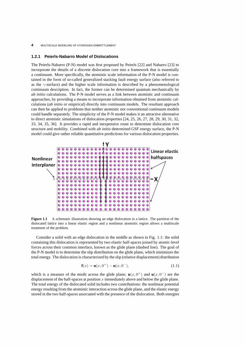
The Peierls-Nabarro (P-N) model was first proposed by Peierls [22] and Nabarro [23] toincorporate the details of a discrete dislocation core intoa framework that is essentiallya continuum. More specifically, the atomistic scale information of the P-N model is con-tained in the form of so-called generalized stacking fault energy surface (also referred toas theγ-surface) and the higher scale information is described by aphenomenologicalcontinuum description. In fact, the former can be determined quantum mechanically byab initio calculations. The P-N model serves as a link between atomistic and continuumapproaches, by providing a means to incorporate information obtained from atomistic cal-culations (ab initio or empirical) directly into continuum models. The resultant approachcan then be applied to problems that neither atomistic nor conventional continuum modelscould handle separately. The simplicity of the P-N model makes it an attractive alternativeto direct atomistic simulations of dislocation properties[24, 25, 26, 27, 28, 29, 30, 31, 32,33, 34, 35, 36]. It provides a rapid and inexpensive route to determine dislocation corestructure and mobility. Combined withab initio determined GSF energy surface, the P-Nmodel could give rather reliable quantitative predictionsfor various dislocation properties.
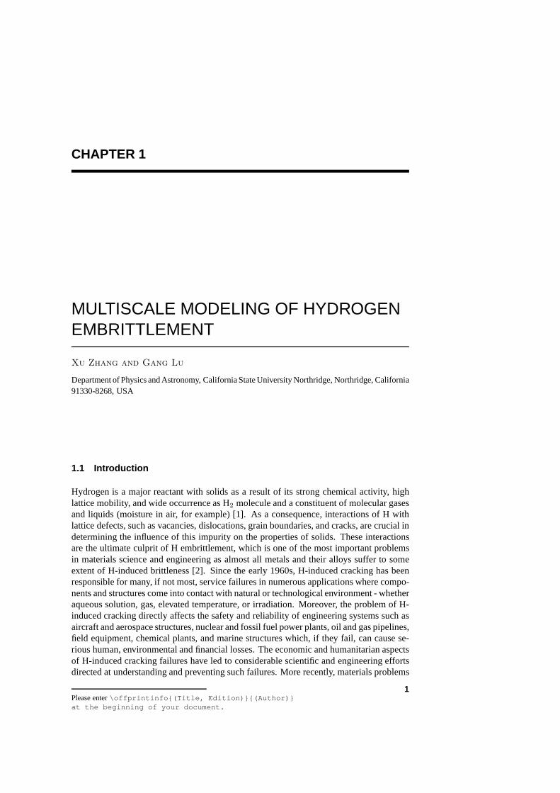
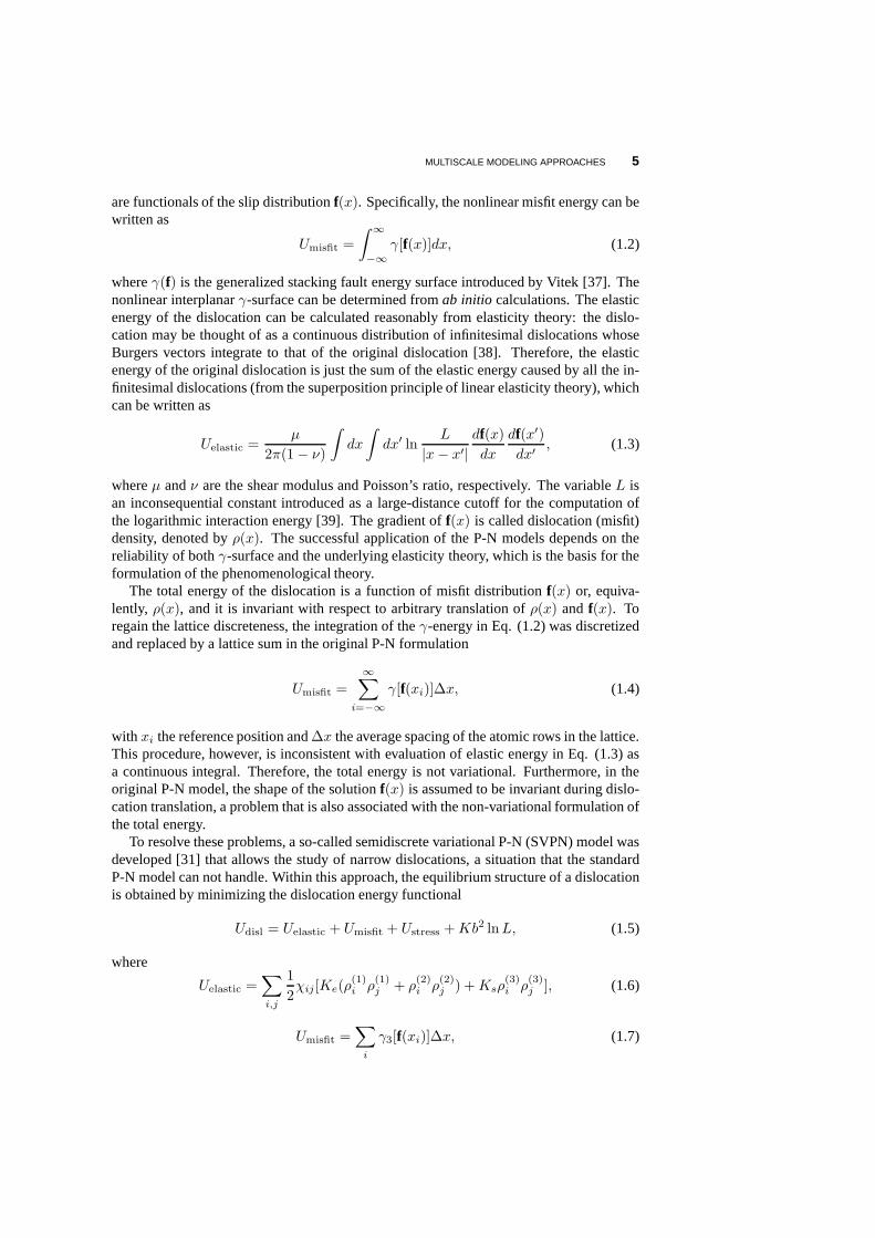
Figure 1.1 A schematic illustration showing an edge dislocation in a lattice. The partition of thedislocated lattice into a linear elastic region and a nonlinear atomistic region allows a multiscaletreatment of the problem.
Consider a solid with an edge dislocation in the middle as shown in Fig. 1.1: the solidcontaining this dislocation is represented by two elastic half-spaces joined by atomic-levelforces across their common interface, known as the glide plane (dashed line). The goal ofthe P-N model is to determine the slip distribution on the glide plane, which minimizes thetotal energy. The dislocation is characterized by the slip (relative displacement) distribution
f(x) = u(x, 0+)− u(x, 0−), (1.1)
which is a measure of the misfit across the glide plane;u(x, 0+) and u(x, 0−) are thedisplacement of the half-spaces at positionx immediately above and below the glide plane.The total energy of the dislocated solid includes two contributions: the nonlinear potentialenergy resulting from the atomistic interaction across theglide plane, and the elastic energystored in the two half-spaces associated with the presence of the dislocation. Both energies
MULTISCALE MODELING APPROACHES 5
are functionals of the slip distributionf(x). Specifically, the nonlinear misfit energy can bewritten as
Umisfit =
∫ ∞
−∞
γ[f(x)]dx, (1.2)
whereγ(f) is the generalized stacking fault energy surface introduced by Vitek [37]. Thenonlinear interplanarγ-surface can be determined fromab initio calculations. The elasticenergy of the dislocation can be calculated reasonably fromelasticity theory: the dislo-cation may be thought of as a continuous distribution of infinitesimal dislocations whoseBurgers vectors integrate to that of the original dislocation [38]. Therefore, the elasticenergy of the original dislocation is just the sum of the elastic energy caused by all the in-finitesimal dislocations (from the superposition principle of linear elasticity theory), whichcan be written as
Uelastic =µ
2π(1− ν)
∫dx
∫dx′ ln
L
|x− x′|
df(x)dx
df(x′)
dx′, (1.3)
whereµ andν are the shear modulus and Poisson’s ratio, respectively. The variableL isan inconsequential constant introduced as a large-distance cutoff for the computation ofthe logarithmic interaction energy [39]. The gradient off(x) is called dislocation (misfit)density, denoted byρ(x). The successful application of the P-N models depends on thereliability of bothγ-surface and the underlying elasticity theory, which is thebasis for theformulation of the phenomenological theory.
The total energy of the dislocation is a function of misfit distribution f(x) or, equiva-lently, ρ(x), and it is invariant with respect to arbitrary translation of ρ(x) andf(x). Toregain the lattice discreteness, the integration of theγ-energy in Eq. (1.2) was discretizedand replaced by a lattice sum in the original P-N formulation
Umisfit =
∞∑i=−∞
γ[f(xi)]∆x, (1.4)
with xi the reference position and∆x the average spacing of the atomic rows in the lattice.This procedure, however, is inconsistent with evaluation of elastic energy in Eq. (1.3) asa continuous integral. Therefore, the total energy is not variational. Furthermore, in theoriginal P-N model, the shape of the solutionf(x) is assumed to be invariant during dislo-cation translation, a problem that is also associated with the non-variational formulation ofthe total energy.
To resolve these problems, a so-called semidiscrete variational P-N (SVPN) model wasdeveloped [31] that allows the study of narrow dislocations, a situation that the standardP-N model can not handle. Within this approach, the equilibrium structure of a dislocationis obtained by minimizing the dislocation energy functional
Udisl = Uelastic + Umisfit + Ustress +Kb2 lnL, (1.5)
where
Uelastic =∑i,j
1
2χij [Ke(ρ
(1)i ρ
(1)j + ρ
(2)i ρ
(2)j ) +Ksρ
(3)i ρ
(3)j ], (1.6)
Umisfit =∑i
γ3[f(xi)]∆x, (1.7)
6 MULTISCALE MODELING OF HYDROGEN EMBRITTLEMENT
Ustress = −∑i,l
x2i − x2
i−1
2ρ(l)i τ
(l)i , (1.8)
with respect to the dislocation misfit density. Here,ρ(1)i , ρ(2)i , andρ(3)i are the edge, verti-
cal, and screw components of the general interplanar misfit density at theith nodal point,respectively, andγ3(f) is the corresponding three-dimensionalγ-surface. The componentsof the applied stress areτ (1) = σ21, τ (2) = σ22, andτ (3) = σ23, respectively. The vari-ablesK, Ke, andKs are the pre-logarithmic elastic energy factors, related tothe shearmodulus, Poisson’s ratio, and the dislocation character [39]. The dislocation density at theith nodal point isρi = (f)i− fi−1)/(xi − xi−1), andχij is the elastic energy kernel [31].
The first term in the energy functionalUelastic is now discretized to be consistent withthe discretized misfit energy, which makes the total energy functional variational. Anothermodification in this approach is that the nonlinear misfit potential in the energy functionalUmisfit is a function of all three components of the nodal misfitf(xi). Namely, in additionto the misfit along the Burgers vector, lateral and even vertical misfits across the glideplane are also included. This allows for the treatment of straight dislocations of arbitraryorientation in arbitrary glide planes [33, 32]. Furthermore, because the misfit vectorf(xi) isallowed to change during the process of dislocation translation, the energy barrier (referredto as the Peierls barrier) can be significantly lowered compared to the corresponding valuetaken from a rigid translation. The response of a dislocation to an applied stress is achievedby minimization of the energy functional with respect toρi at the given value of the appliedstressτ (l)i . An instability is reached when an optimal solution forρi no longer exists,which is manifested numerically by the failure of the minimization procedure to converge.The Peierls stress is defined as the critical value of the applied stress that gives rise tothis instability. The SVPN model has been applied to study various interesting materialproblems related to dislocation phenomena [33, 32, 34, 35, 36].
1.2.2 Quantum mechanics/molecular mechanics method
In atomistic modeling of materials, quantum mechanics (QM)is necessary for a propertreatment of phenomena such as bond-breaking, charge transfer, electronic and optical ex-citations and magnetism, etc; however, owing to its computational demand, the applicationof QM has to be restricted to relatively small systems consisting of up to a few hundredsof atoms. On the other hand, atomistic simulations based on empirical interatomic po-tentials are often capable of describing small-amplitude vibrations and torsions, elasticdeformation, electrostatic interactions, etc., in many materials. Termed as molecular me-chanical (MM) methods, these empirical atomistic approaches can treat millions of atomsor more. Therefore algorithms that combine quantum mechanics and molecular mechanics(QM/MM) poise to offer a promising solution to the computational challenge in atomisticsimulations of materials [40, 41, 42].
For many molecular systems that are of interest in chemistryand biochemistry, one canpartition the QM/MM system by cutting chemical bonds linking the QM and MM partsand then saturate the dangling bonds at the boundary of QM region by so-called link atoms[41, 43, 44]. This procedure and the similar ones can be justified because of the presenceof well-defined and localized chemical bonds in such molecular systems. Unfortunately,for metallic materials, the procedure is no longer valid owing to the delocalized nature ofmetallic bonding; it becomes impractical to cut and saturate bonds. In fact, the very conceptof chemical bonds becomes less appropriate than the band picture for metals. Therefore,more sophisticated ideas have to be developed to deal with metallic cohesion represented
MULTISCALE MODELING APPROACHES 7
by the delocalized electron states across the QM/MM boundary. As a result, far fewerQM/MM-like simulations have been attempted in metallic systems [42, 45, 46, 47, 48, 49].Here, we present some recent development of such ideas for modeling metallic materials[50, 51, 52, 53, 42].
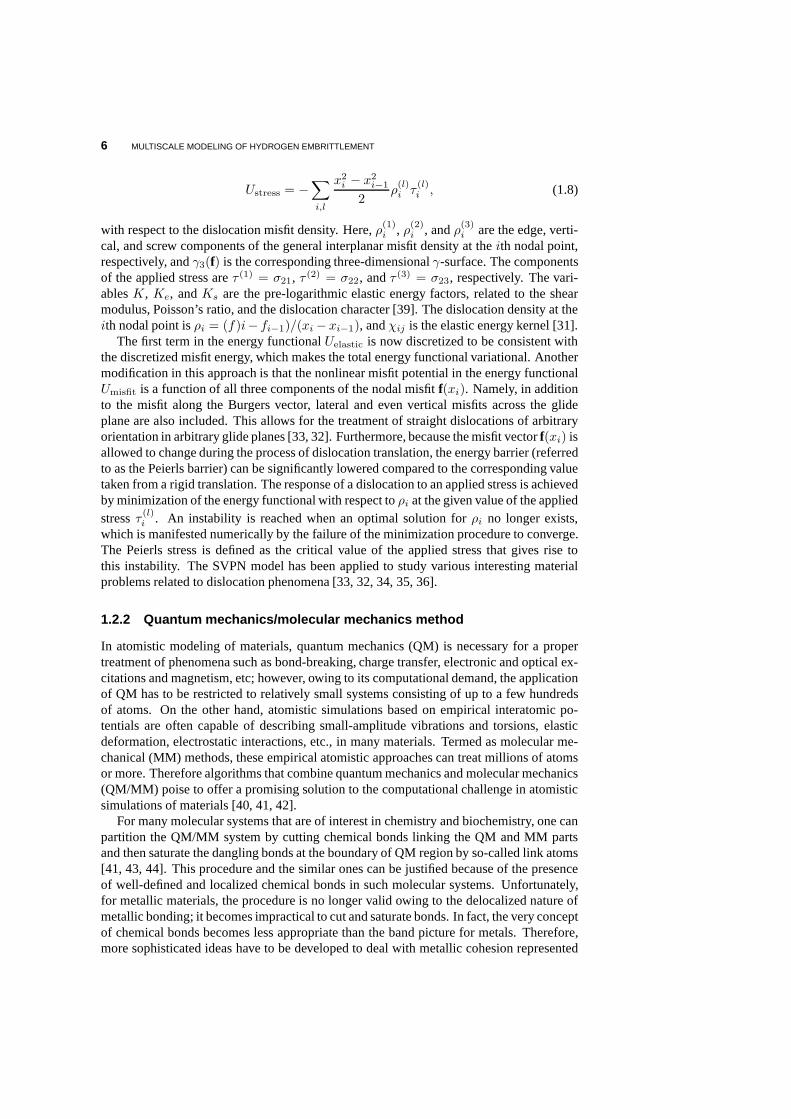
In a QM/MM simulation, the computational domain is partitioned into two regions: re-gion I is the primary region where QM simulations are performed and region II is the sur-rounding region where classical atomistic simulations arecarried out. Although differentlevels of QM simulations could be employed in region I, here we focus on the Kohn-Shamdensity functional theory (KS-DFT) [19]. Similarly, although many empirical potentialscould be used in region II, we choose the embedded-atom method (EAM) [54] as an exam-ple for MM calculations. The total energy of a system including the energy of the region I,the energy for the region II, and the interaction energy between them can be expressed as
Etot[I + II] = EDFT[I] + Eint[I, II] + EEAM[II]. (1.9)
The interaction between regions I and II is at the heart of anyQM/MM method. Dependingon the formulation of the interaction energy, the QM/MM methods can be divided intotwo categories: mechanical coupling and quantum coupling.In the quantum coupling, theinteraction energyEint[I, II] is formulated by DFT; the quantum mechanical calculation forregion I is carried out in the presence of region II; and a single-particle embedding potentialthat represents the quantum mechanical effects of region IIenters the QM Hamiltonian ofregion I. On the other hand, in the mechanical coupling, one performs quantum mechanicalsimulation of region I in the absence of region II, and treatsthe interaction energyEint[I, II]at the MM level.
Figure 1.2 Schematic domain partition in the QM/MM method with an edge dislocation as anexample. Blue and magenta spheres represent the atoms belonging to region I and region II,respectively. The dashed box representsΩ
I, and the solid box represents the periodic boxΩb.
The charge density of region IρI is confined withinΩI, and the periodic boundary conditions areimposed overΩb. From reference [53].
8 MULTISCALE MODELING OF HYDROGEN EMBRITTLEMENT
1.2.2.1 Quantum Coupling The self-consistent determination of the interaction energyat a QM level is the hallmark of the quantum coupling approach. The spatial partition ofthe entire system is shown in Fig. 1.2. In specific, the total energy can be expressed as
Etot[ρtot;Rtot] = minρIEKS[ρ
I;RI] + EintOF[ρ
I, ρII;RI,RII]+ EMM[RII], (1.10)
whereRtot ≡ RI ⋃RII, RI andRII denote atomic coordinates in region I and II respec-tively. The charge density of region I,ρI, which is the degree of the freedom of theproblem, is determined self-consistently by minimizing the total energy functional Eq.(1.10). We associate each MM atom in region II with an atomic-centered electron density(ρat) and a pseudopotential; both of them are constructeda priori. The charge densityof region II,ρII, is defined as a superposition of atomic-centered charge densitiesρat viaρII(r) =
∑i∈II ρ
at(r − Ri), which only changes upon the relaxation of region II ions.The total charge densityρtot is given byρtot = ρI + ρII. The interaction energy betweenregion I and II,Eint
OF, formulated by Orbital-Free Density Functional Theory (OF-DFT)[56, 57, 58] is defined as follows
EintOF[ρ
I, ρII;RI,RII] = EOF[ρtot;Rtot]− EOF[ρ
I;RI]− EOF[ρII;RII]. (1.11)
The unique feature of OF-DFT is that it allows a QM calculation of energetics by knowingonly the charge density. The accuracy of OF-DFT is in between KS-DFT and EAM, whichis consistent to its usage in the QM/MM method. Finally, the EAM method was developedspecifically to treat metallic systems.µemb[ρ
I, ρII] termed as embedding potential, is ofcrucial importance to the QM/MM method, and is defined as a functional derivative of theinteraction energyEint
OF with respect toρI,
µemb(r) ≡δEint
OF[ρI, ρII;RI,RII]
δρI. (1.12)
µemb(r) represents the effective single-particle potential that the region I electrons feeldue to the presence of the region II atoms (both electrons andions). We have recentlydeveloped a quantum coupling approach in which the interaction energy is calculated byKS-DFT, thus overcomes the limitations of OF-DFT. Based on the constrained DFT, themethod is more general and is particularly useful for magnetic materials [55].
1.2.2.2 Mechanical coupling In the mechanical coupling, the interaction energyEint
is evaluated with EAM calculations,
Eint[I, II] = EEAM[I + II]− EEAM[I]− EEAM[II], (1.13)
and thus Eq. (1.9) becomes
Etot[I + II] = EDFT[I] + EEAM[I + II]− EEAM[I]. (1.14)
The advantage of the mechanical coupling is simplicity [59]. It demands nothing beyondwhat is required for a DFT cluster calculation and two classical MM calculations (one forthe entire system and the other for a cluster of region I). On the other hand, the quantumcoupling allows a more accurate description, in particular, for the electronic structure ofregion I. For example, the fictitious surface states due to the cluster calculation of region Iin the mechanical coupling can be eliminated in the quantum coupling [52]. Of course, thequantum coupling is more complicated than the mechanical coupling in general.
MULTISCALE MODELING APPROACHES 9
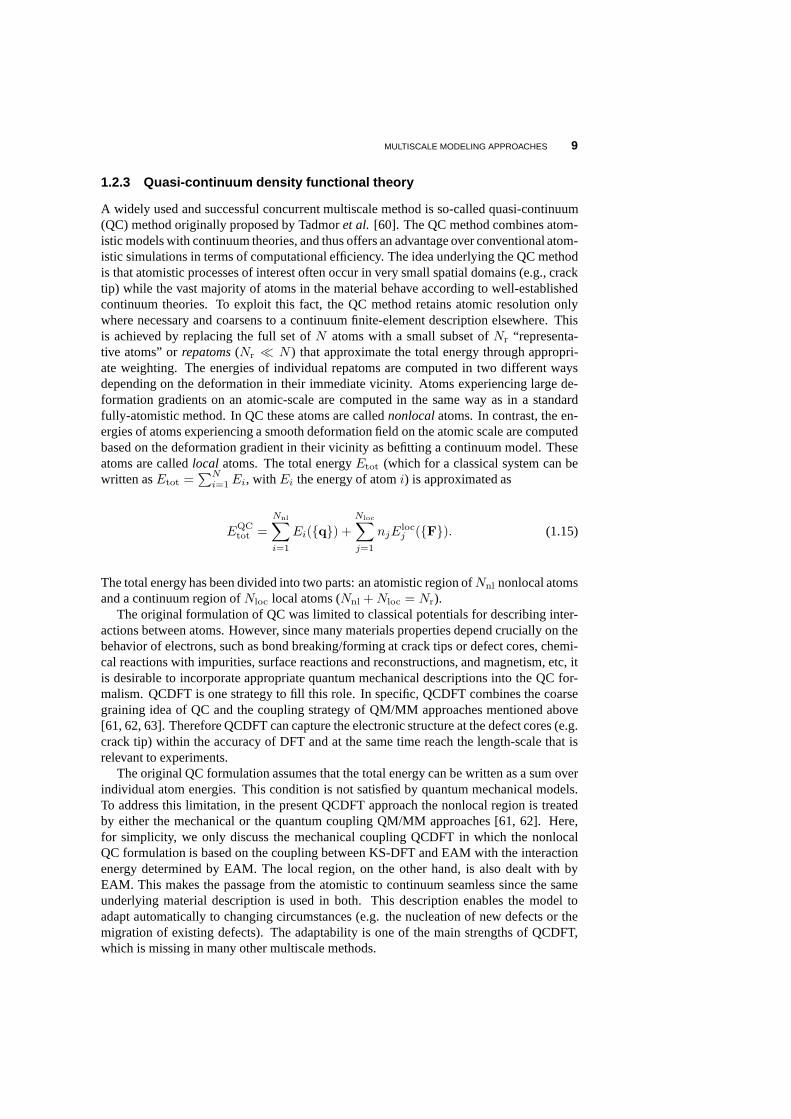
1.2.3 Quasi-continuum density functional theory
A widely used and successful concurrent multiscale method is so-called quasi-continuum(QC) method originally proposed by Tadmoret al. [60]. The QC method combines atom-istic models with continuum theories, and thus offers an advantage over conventional atom-istic simulations in terms of computational efficiency. Theidea underlying the QC methodis that atomistic processes of interest often occur in very small spatial domains (e.g., cracktip) while the vast majority of atoms in the material behave according to well-establishedcontinuum theories. To exploit this fact, the QC method retains atomic resolution onlywhere necessary and coarsens to a continuum finite-element description elsewhere. Thisis achieved by replacing the full set ofN atoms with a small subset ofNr “representa-tive atoms” orrepatoms (Nr ≪ N ) that approximate the total energy through appropri-ate weighting. The energies of individual repatoms are computed in two different waysdepending on the deformation in their immediate vicinity. Atoms experiencing large de-formation gradients on an atomic-scale are computed in the same way as in a standardfully-atomistic method. In QC these atoms are callednonlocal atoms. In contrast, the en-ergies of atoms experiencing a smooth deformation field on the atomic scale are computedbased on the deformation gradient in their vicinity as befitting a continuum model. Theseatoms are calledlocal atoms. The total energyEtot (which for a classical system can bewritten asEtot =
∑N
i=1 Ei, with Ei the energy of atomi) is approximated as
EQCtot =
Nnl∑i=1
Ei(q) +
Nloc∑j=1
njElocj (F). (1.15)
The total energy has been divided into two parts: an atomistic region ofNnl nonlocal atomsand a continuum region ofNloc local atoms (Nnl +Nloc = Nr).
The original formulation of QC was limited to classical potentials for describing inter-actions between atoms. However, since many materials properties depend crucially on thebehavior of electrons, such as bond breaking/forming at crack tips or defect cores, chemi-cal reactions with impurities, surface reactions and reconstructions, and magnetism, etc, itis desirable to incorporate appropriate quantum mechanical descriptions into the QC for-malism. QCDFT is one strategy to fill this role. In specific, QCDFT combines the coarsegraining idea of QC and the coupling strategy of QM/MM approaches mentioned above[61, 62, 63]. Therefore QCDFT can capture the electronic structure at the defect cores (e.g.crack tip) within the accuracy of DFT and at the same time reach the length-scale that isrelevant to experiments.
The original QC formulation assumes that the total energy can be written as a sum overindividual atom energies. This condition is not satisfied byquantum mechanical models.To address this limitation, in the present QCDFT approach the nonlocal region is treatedby either the mechanical or the quantum coupling QM/MM approaches [61, 62]. Here,for simplicity, we only discuss the mechanical coupling QCDFT in which the nonlocalQC formulation is based on the coupling between KS-DFT and EAM with the interactionenergy determined by EAM. The local region, on the other hand, is also dealt with byEAM. This makes the passage from the atomistic to continuum seamless since the sameunderlying material description is used in both. This description enables the model toadapt automatically to changing circumstances (e.g. the nucleation of new defects or themigration of existing defects). The adaptability is one of the main strengths of QCDFT,which is missing in many other multiscale methods.
10 MULTISCALE MODELING OF HYDROGEN EMBRITTLEMENT
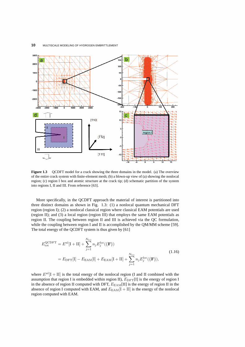
Figure 1.3 QCDFT model for a crack showing the three domains in the model. (a) The overviewof the entire crack system with finite-element mesh; (b) a blown-up view of (a) showing the nonlocalregion; (c) region I box and atomic structure at the crack tip; (d) schematic partition of the systeminto regions I, II and III. From reference [63].
More specifically, in the QCDFT approach the material of interest is partitioned intothree distinct domains as shown in Fig. 1.3: (1) a nonlocal quantum mechanical DFTregion (region I); (2) a nonlocal classical region where classical EAM potentials are used(region II); and (3) a local region (region III) that employsthe same EAM potentials asregion II. The coupling between region II and III is achievedvia the QC formulation,while the coupling between region I and II is accomplished bythe QM/MM scheme [59].The total energy of the QCDFT system is thus given by [61]
EQCDFTtot = Enl[I + II] +
Nloc∑j=1
njElocj (F)
= EDFT[I]− EEAM[I] + EEAM[I + II] +
Nloc∑j=1
njElocj (F),
(1.16)
whereEnl[I + II] is the total energy of the nonlocal region (I and II combined with theassumption that region I is embedded within region II),EDFT[I] is the energy of region Iin the absence of region II computed with DFT,EEAM[II] is the energy of region II in theabsence of region I computed with EAM, andEEAM[I + II] is the energy of the nonlocalregion computed with EAM.
MULTISCALE MODELING OF HYDROGEN EMBRITTLEMENT 11
Other combinations of quantum mechanical and classical atomistic methods may alsobe implemented in QCDFT. The advantage of the present implementation is its simplic-ity; it has nothing more than a DFT calculation and an EAM-QC calculation. Anotheradvantage of the QCDFT method is that, if region I contains multiple atomic species whileregion II contains only one atom type, there is no need to develop reliable EAM potentialsto describe each species and their interactions. This is because if the various species ofatoms are well within region I, the energy contributions of these atoms are canceled outin the total energy calculation. This advantage renders themethod useful in dealing withimpurities, which is an exceedingly difficult task for conventional empirical simulations.
The equilibrium structure of the system is obtained by minimizing the total energy inEq. (1.16) with respect to all degrees of freedom. Because the time required to evaluateEDFT[I] is considerably more than that required for computationof the other EAM termsin EQCDFT
tot , an alternate relaxation scheme turns out to be useful. The total system canbe relaxed by using conjugate gradient approach on the DFT atoms alone, while fullyrelaxing the EAM atoms in region II and the displacement fieldin region III at each step.An auxiliary energy function can be defined as
E′[qI] ≡ minqII,qIII
EQCDFTtot [q], (1.17)
which allows for the following relaxation scheme: (i) minimizeEQCDFTtot with respect to
the atoms in regions II (qII) and the atoms in region III (qIII), while holding the atomsin region I fixed; (ii) calculateEQCDFT
tot [q], and the forces on the region I atoms; (iii)perform one step of conjugate gradient minimization ofE′; (iv) repeat until the systemis relaxed. In this manner, the number of DFT calculations performed is greatly reduced,albeit at the expense of more EAM and local QC calculations. It has been shown shownthat the total number of DFT energy calculations for the relaxation of an entire system isabout the same as that required for DFT relaxation of region Ialone.
1.3 Multiscale Modeling of Hydrogen Embrittlement
In the past decade, we have used multiscale modeling to studysome key problems inH embrittlement of metals by focusing on H-defect interactions, which are summarizedbelow.
1.3.1 Hydrogen Enhanced Local Plasticity
In recent years, a unified understanding of H embrittlement is emerging based on the keyconcept of hydrogen enhanced local plasticity (HELP) [1]. There is a large body of ex-perimental evidence suggesting that H strongly affects plastic deformation in metals in amanner leading to enhanced fracture. One of the most convincing experimental evidence ofHELP is the controlledin situ TEM observation that is performed in real time and at highspatial resolution [7]. Observations were made on specimens that were under stress, butthe deformation processes had ceased to operate in vacuum. On addingH2 gas to the en-vironmental cell, dislocations began to move. Subsequently removal of theH2 gas causeda cessation of the dislocation motion, and the cycle could berepeated many times. This Henhanced dislocation mobility has been observed for screw,edge, and mixed dislocationsas well as for isolated dislocations and dislocation tangles. Observations have been madein a wide range of materials with different crystal structures, including Fe, Ni, steels, Al
12 MULTISCALE MODELING OF HYDROGEN EMBRITTLEMENT
and Al alloys, Ti and Ti-alloys, and Ni3Al [5, 64, 8, 9, 65, 66, 67, 68, 69, 70]. Anotherimportant result, which is believed to be responsible for H embrittlement is H-induced slipplanarity. It has been revealed by microscopic observations that solute H atoms can inhibitdislocation cross-slip in Al, austenitic stainless steels, Ni, NiCo, and Ni-based superalloy,leading to slip planarity [71, 72, 73, 74, 75]. This slip planarity forces dislocations from agiven source to remain localized in narrow slip bands because the relaxation of dislocationpile-ups via cross-slip is suppressed. As a consequence, a micro-crack may be initiated infront of a pile-up when the stress intensity factor reaches its critical value over there. Incontrast to the vast body of experimental evidence, theoretical studies of the HELP mech-anism are scarce. The SVPN and QM/MM calculations have been performed to gain anunderstanding of the physics behind the HELP mechanism [34,53, 76, 77].
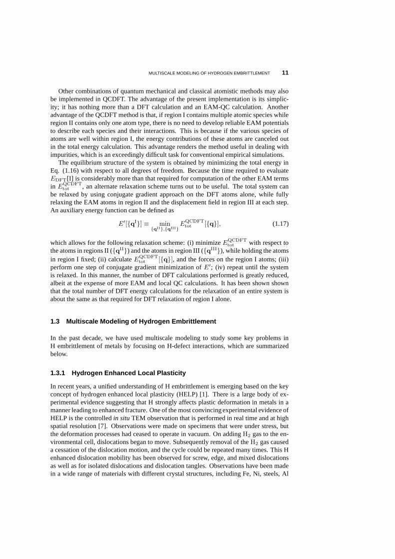
In the SVPN approach,ab initio calculations are carried out for for theγ-surface ofAl with H impurities placed at the interstitial sites [34]. Theγ-surfaces for both pure Aland the Al + H systems are shown in Fig. 1.4. Comparing the twoγ-surfaces, one findsan overall reduction (up to 50%) inγ-energy in the presence of H, which is attributedto the change of atomic bonding across the glide plane, from covalent-like to ionic-like[78]. This reduction ofγ-energy could change dislocation properties significantly. Forexample, one expects that dislocations would be emitted more easily from a crack tip whenH is present based on the lowering of the unstable stacking fault energy along the[121]direction [79]. In fact, this prediction is in accordance with atomistic simulations for Ni,where dislocations are found to be emitted more rapidly froma crack tip in the presence ofH [80].
Figure 1.4 Theγ-surface (J/m2) for displacements along a (111) plane for (a) pure Al and (b)Al +H systems. The corners of the plane and its center correspondto identical equilibrium configurations(i.e., the ideal lattice). The two surfaces are displayed inexactly the same perspective and on thesame energy scale to facilitate comparison of important features. From reference [34].
The core properties of four different dislocations, screw (0), 30, 60, and edge (90)have been studied using the SVPN model. The Peierls stress for these dislocations is shownin Table 1.1. It was found that the Peierls stress, which is the minimum stress to move astationary dislocation, is reduced by more than an order of magnitude in the presence of H.Moreover this H-enhanced mobility is observed for screw, edge, and mixed dislocations,which is compatible with the experimental results. This result invalidates the perceptionthat the only plausible explanation of HELP must be based on elastic interactions amongdislocations and that dislocation-lattice interaction isnot important [1]. On the contrary, itwas found that the dislocation-lattice interaction is veryimportant and that the dislocation
MULTISCALE MODELING OF HYDROGEN EMBRITTLEMENT 13
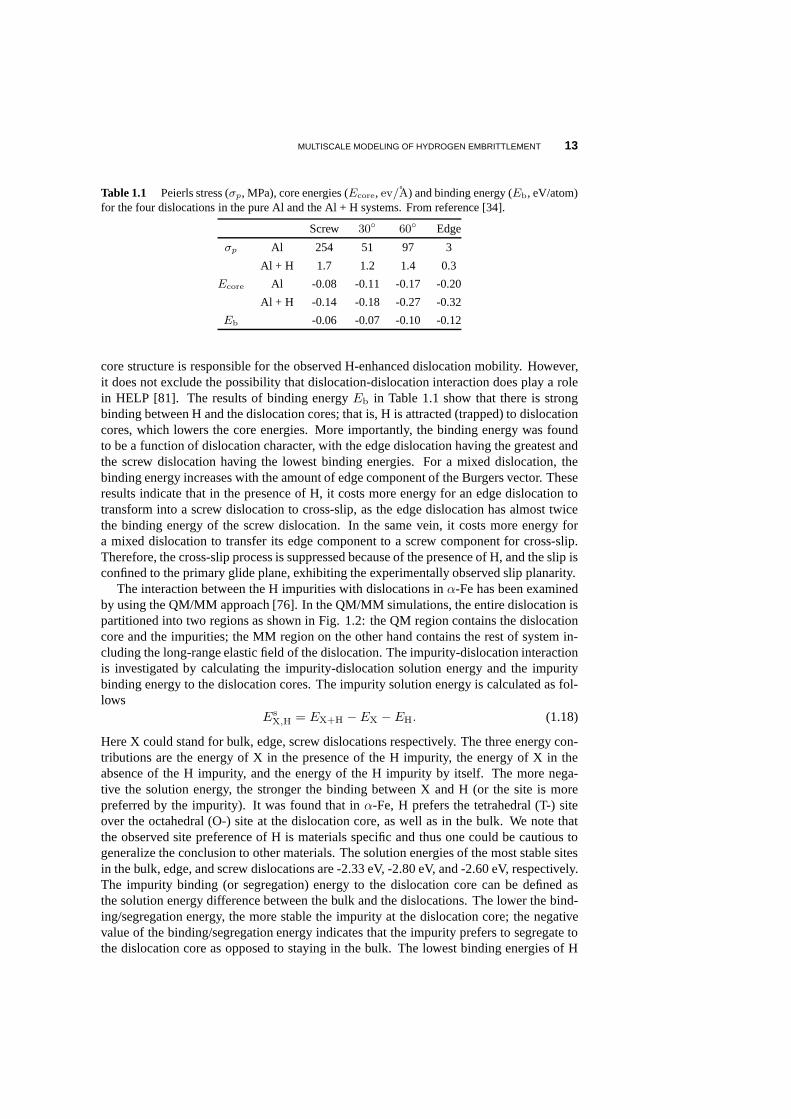
Table 1.1 Peierls stress (σp, MPa), core energies (Ecore, ev/A) and binding energy (Eb, eV/atom)for the four dislocations in the pure Al and the Al + H systems.From reference [34].
Screw 30
60 Edge
σp Al 254 51 97 3
Al + H 1.7 1.2 1.4 0.3
Ecore Al -0.08 -0.11 -0.17 -0.20
Al + H -0.14 -0.18 -0.27 -0.32
Eb -0.06 -0.07 -0.10 -0.12
core structure is responsible for the observed H-enhanced dislocation mobility. However,it does not exclude the possibility that dislocation-dislocation interaction does play a rolein HELP [81]. The results of binding energyEb in Table 1.1 show that there is strongbinding between H and the dislocation cores; that is, H is attracted (trapped) to dislocationcores, which lowers the core energies. More importantly, the binding energy was foundto be a function of dislocation character, with the edge dislocation having the greatest andthe screw dislocation having the lowest binding energies. For a mixed dislocation, thebinding energy increases with the amount of edge component of the Burgers vector. Theseresults indicate that in the presence of H, it costs more energy for an edge dislocation totransform into a screw dislocation to cross-slip, as the edge dislocation has almost twicethe binding energy of the screw dislocation. In the same vein, it costs more energy fora mixed dislocation to transfer its edge component to a screwcomponent for cross-slip.Therefore, the cross-slip process is suppressed because ofthe presence of H, and the slip isconfined to the primary glide plane, exhibiting the experimentally observed slip planarity.
The interaction between the H impurities with dislocationsin α-Fe has been examinedby using the QM/MM approach [76]. In the QM/MM simulations, the entire dislocation ispartitioned into two regions as shown in Fig. 1.2: the QM region contains the dislocationcore and the impurities; the MM region on the other hand contains the rest of system in-cluding the long-range elastic field of the dislocation. Theimpurity-dislocation interactionis investigated by calculating the impurity-dislocation solution energy and the impuritybinding energy to the dislocation cores. The impurity solution energy is calculated as fol-lows
EsX,H = EX+H − EX − EH. (1.18)
Here X could stand for bulk, edge, screw dislocations respectively. The three energy con-tributions are the energy of X in the presence of the H impurity, the energy of X in theabsence of the H impurity, and the energy of the H impurity by itself. The more nega-tive the solution energy, the stronger the binding between Xand H (or the site is morepreferred by the impurity). It was found that inα-Fe, H prefers the tetrahedral (T-) siteover the octahedral (O-) site at the dislocation core, as well as in the bulk. We note thatthe observed site preference of H is materials specific and thus one could be cautious togeneralize the conclusion to other materials. The solutionenergies of the most stable sitesin the bulk, edge, and screw dislocations are -2.33 eV, -2.80eV, and -2.60 eV, respectively.The impurity binding (or segregation) energy to the dislocation core can be defined asthe solution energy difference between the bulk and the dislocations. The lower the bind-ing/segregation energy, the more stable the impurity at thedislocation core; the negativevalue of the binding/segregation energy indicates that theimpurity prefers to segregate tothe dislocation core as opposed to staying in the bulk. The lowest binding energies of H
14 MULTISCALE MODELING OF HYDROGEN EMBRITTLEMENT
to the screw and the edge dislocation are -0.27 eV and -0.47 eV, respectively. Therefore,the H impurity is energetically most stable in the edge dislocation, less stable in the screwdislocation and least stable in the bulk, similar to the preceding results of Al. We have alsoperformed QM/MM calculations for Al dislocations and find a binding energy between Hand the edge dislocation of -0.12 eV [53], which is identicalto the previous P-N modelresult. However, H has a weaker binding to dislocations in Mgwhere the binding energiesare -0.03 eV and -0.05 eV for the screw and edge dislocations,respectively [77].
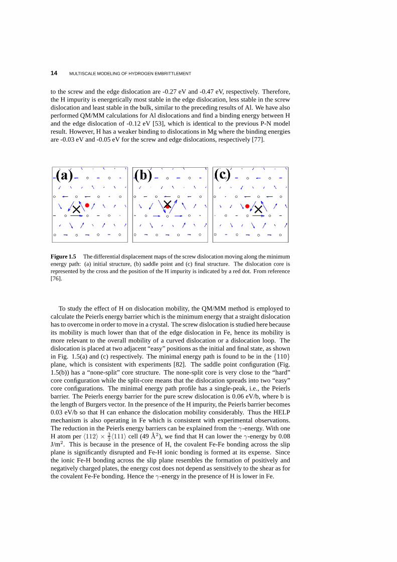
Figure 1.5 The differential displacement maps of the screw dislocation moving along the minimumenergy path: (a) initial structure, (b) saddle point and (c)final structure. The dislocation core isrepresented by the cross and the position of the H impurity isindicated by a red dot. From reference[76].
To study the effect of H on dislocation mobility, the QM/MM method is employed tocalculate the Peierls energy barrier which is the minimum energy that a straight dislocationhas to overcome in order to move in a crystal. The screw dislocation is studied here becauseits mobility is much lower than that of the edge dislocation in Fe, hence its mobility ismore relevant to the overall mobility of a curved dislocation or a dislocation loop. Thedislocation is placed at two adjacent “easy” positions as the initial and final state, as shownin Fig. 1.5(a) and (c) respectively. The minimal energy pathis found to be in the110plane, which is consistent with experiments [82]. The saddle point configuration (Fig.1.5(b)) has a “none-split” core structure. The none-split core is very close to the “hard”core configuration while the split-core means that the dislocation spreads into two “easy”core configurations. The minimal energy path profile has a single-peak, i.e., the Peierlsbarrier. The Peierls energy barrier for the pure screw dislocation is 0.06 eV/b, where b isthe length of Burgers vector. In the presence of the H impurity, the Peierls barrier becomes0.03 eV/b so that H can enhance the dislocation mobility considerably. Thus the HELPmechanism is also operating in Fe which is consistent with experimental observations.The reduction in the Peierls energy barriers can be explained from theγ-energy. With oneH atom per〈112〉 × 3
2 〈111〉 cell (49 A2), we find that H can lower theγ-energy by 0.08J/m2. This is because in the presence of H, the covalent Fe-Fe bonding across the slipplane is significantly disrupted and Fe-H ionic bonding is formed at its expense. Sincethe ionic Fe-H bonding across the slip plane resembles the formation of positively andnegatively charged plates, the energy cost does not depend as sensitively to the shear as forthe covalent Fe-Fe bonding. Hence theγ-energy in the presence of H is lower in Fe.
MULTISCALE MODELING OF HYDROGEN EMBRITTLEMENT 15
1.3.2 Hydrogen Assisted Cracking
The presence of H is known to promote crack growth in a varietyof technologically impor-tant materials [83]. A recent work on large-scale atomisticsimulations of Al has suggestedan interesting mechanism for ductile fracture, which depends on dislocation mobility andpinning behavior [84]. Based on EAM simulations, the authors have observed that thecleavage fracture can occur after emission of dislocationsfrom the crack tip. The emitteddislocations can shield the crack tip, so that the macroscopic toughness exceeds the Grif-fith value, and hence the failure is a combination of both “brittle-like” and “ductile-like”phenomena. To fully address this problem, QCDFT that combinesab initio calculationsfor H-metal interactions near the crack tip and large-scaleQC simulations for the rest ofthe system, is required. Here, we study H-assisted crackingin Al which is at the heart ofH embrittlement. If one understands the fundamental processes of H assisted cracking, itmight be possible to establish connections between the various mechanisms and arrive at acomprehensive picture of H embrittlement.
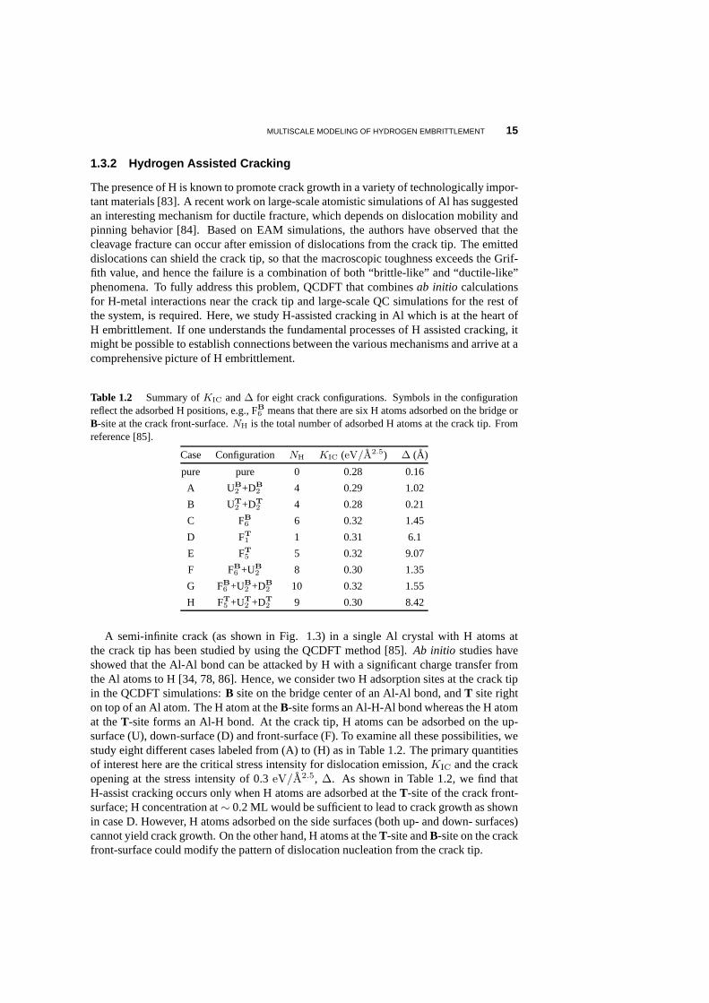
Table 1.2 Summary ofKIC and∆ for eight crack configurations. Symbols in the configurationreflect the adsorbed H positions, e.g., FB
6 means that there are six H atoms adsorbed on the bridge orB-site at the crack front-surface.NH is the total number of adsorbed H atoms at the crack tip. Fromreference [85].
Case Configuration NH KIC (eV/A2.5) ∆ (A)
pure pure 0 0.28 0.16
A UB
2 +DB
2 4 0.29 1.02
B UT
2 +DT
2 4 0.28 0.21
C FB
6 6 0.32 1.45
D FT
1 1 0.31 6.1
E FT
5 5 0.32 9.07
F FB
6 +UB
2 8 0.30 1.35
G FB
6 +UB
2 +DB
2 10 0.32 1.55
H FT
5 +UT
2 +DT
2 9 0.30 8.42
A semi-infinite crack (as shown in Fig. 1.3) in a single Al crystal with H atoms atthe crack tip has been studied by using the QCDFT method [85].Ab initio studies haveshowed that the Al-Al bond can be attacked by H with a significant charge transfer fromthe Al atoms to H [34, 78, 86]. Hence, we consider two H adsorption sites at the crack tipin the QCDFT simulations:B site on the bridge center of an Al-Al bond, andT site righton top of an Al atom. The H atom at theB-site forms an Al-H-Al bond whereas the H atomat theT-site forms an Al-H bond. At the crack tip, H atoms can be adsorbed on the up-surface (U), down-surface (D) and front-surface (F). To examine all these possibilities, westudy eight different cases labeled from (A) to (H) as in Table 1.2. The primary quantitiesof interest here are the critical stress intensity for dislocation emission,KIC and the crackopening at the stress intensity of 0.3eV/A2.5, ∆. As shown in Table 1.2, we find thatH-assist cracking occurs only when H atoms are adsorbed at the T-site of the crack front-surface; H concentration at∼ 0.2 ML would be sufficient to lead to crack growth as shownin case D. However, H atoms adsorbed on the side surfaces (both up- and down- surfaces)cannot yield crack growth. On the other hand, H atoms at theT-site andB-site on the crackfront-surface could modify the pattern of dislocation nucleation from the crack tip.
16 MULTISCALE MODELING OF HYDROGEN EMBRITTLEMENT
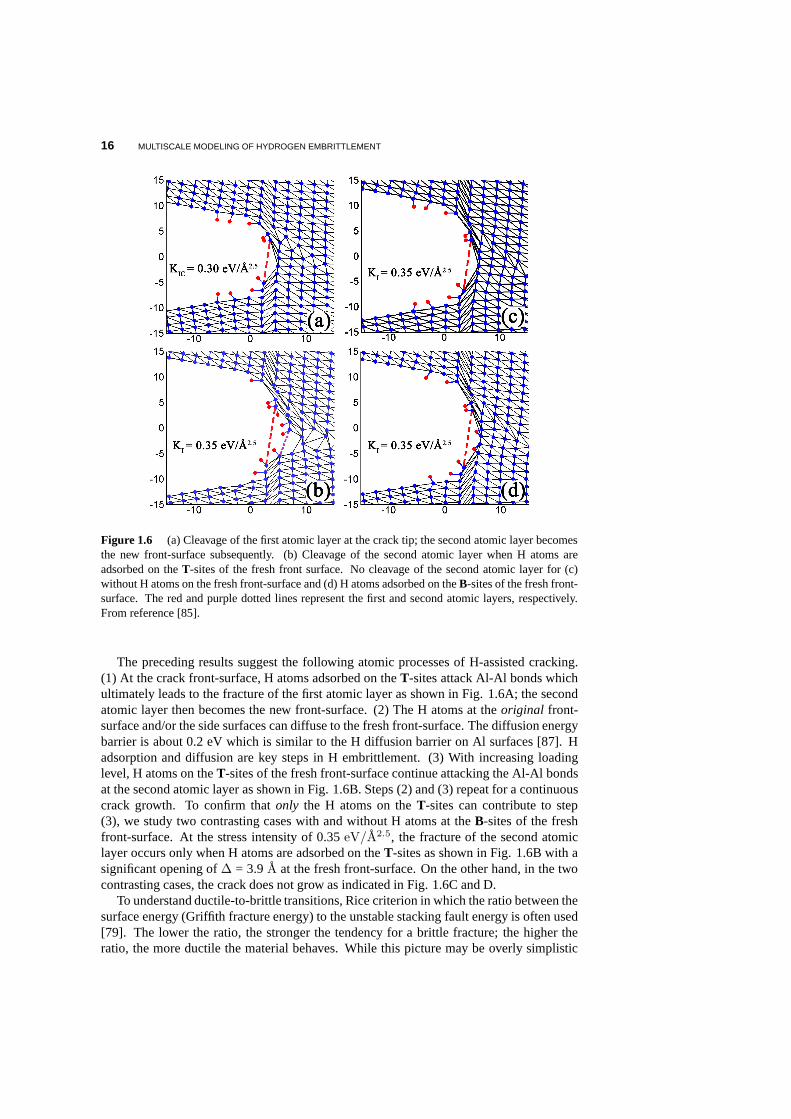
Figure 1.6 (a) Cleavage of the first atomic layer at the crack tip; the second atomic layer becomesthe new front-surface subsequently. (b) Cleavage of the second atomic layer when H atoms areadsorbed on theT-sites of the fresh front surface. No cleavage of the second atomic layer for (c)without H atoms on the fresh front-surface and (d) H atoms adsorbed on theB-sites of the fresh front-surface. The red and purple dotted lines represent the first and second atomic layers, respectively.From reference [85].
The preceding results suggest the following atomic processes of H-assisted cracking.(1) At the crack front-surface, H atoms adsorbed on theT-sites attack Al-Al bonds whichultimately leads to the fracture of the first atomic layer as shown in Fig. 1.6A; the secondatomic layer then becomes the new front-surface. (2) The H atoms at theoriginal front-surface and/or the side surfaces can diffuse to the fresh front-surface. The diffusion energybarrier is about 0.2 eV which is similar to the H diffusion barrier on Al surfaces [87]. Hadsorption and diffusion are key steps in H embrittlement. (3) With increasing loadinglevel, H atoms on theT-sites of the fresh front-surface continue attacking the Al-Al bondsat the second atomic layer as shown in Fig. 1.6B. Steps (2) and(3) repeat for a continuouscrack growth. To confirm thatonly the H atoms on theT-sites can contribute to step(3), we study two contrasting cases with and without H atoms at the B-sites of the freshfront-surface. At the stress intensity of 0.35eV/A2.5, the fracture of the second atomiclayer occurs only when H atoms are adsorbed on theT-sites as shown in Fig. 1.6B with asignificant opening of∆ = 3.9A at the fresh front-surface. On the other hand, in the twocontrasting cases, the crack does not grow as indicated in Fig. 1.6C and D.
To understand ductile-to-brittle transitions, Rice criterion in which the ratio between thesurface energy (Griffith fracture energy) to the unstable stacking fault energy is often used[79]. The lower the ratio, the stronger the tendency for a brittle fracture; the higher theratio, the more ductile the material behaves. While this picture may be overly simplistic
MULTISCALE MODELING OF HYDROGEN EMBRITTLEMENT 17
for a quantitative analysis, it does give a useful insight for general trends and can even leadto predictions that have been verified experimentally [88].We have used the Rice criterionto examine H embrittlement in Mg and find that the H impuritiesgenerally lower the ratioleading to the brittle fracture of Mg [77].
1.3.3 Crucial Role of Vacancies
Vacancies, being ubiquitously present in solids and havingthe ability to act as impuritytraps, could play a central role in H embrittlement as hintedby some recent experiments.One set of experiments has established that H could induce superabundant vacancy for-mation in a number of metals, such as Pd, Ni, Cr, etc. [89, 90].The estimated vacancyconcentration,Cv, in these systems can reach a value as at 23% [90]. A conclusion drawnfrom these experiments is that H atoms, originally at bulk interstitials are trapped at vacan-cies in multiple numbers with rather high binding energies.The consequence of H trappingis that the formation energy of a vacancy defect is lowered bya significant amount. Suchreduction in the vacancy formation energy could result in a drastic increase (107 fold forFe) of equilibrium vacancy concentrations [91]. The superabundant vacancy formation inturn provides more trapping sites for H impurities, effectively increasing the apparent Hsolubility in metals by many orders of magnitude. For example, it was observed experimen-tally that about 1000 at. ppm of H atoms can enter Al accompanied by vacancy formationat the surface under aggressive H charging conditions, which should be contrasted with theequilibrium solubility of H in Al of about10−5 at. ppm at room temperature where theexperiments were carried out [92]; this is a staggering change of eight orders of magnitudein concentration. It was further observed that the H-vacancy defects clustered and formedplatelets lying on the111 planes, which directly lead to void formation or crack nucle-ation on the111 cleavage planes [92]. Because of the extremely low solubility of H inmetals such as aluminum, experiments are usually difficult and results are dependent on Hcharging conditions; for such systems, first-principles calculations are particularly usefulto complement experiments.
First-principles calculations show that the tetrahedral interstitial site for H atoms in bulkAl is slightly more favorable than the octahedral interstitial site by 0.07 eV. And the H atomprefers to occupy the vacancy site over the interstitial tetrahedral site in bulk by 0.40 eVin excellent agreement with the experimental value of 0.52 eV [1]. The lowest energyposition for the H atom in the presence of a vacancy is not at the geometric center of thevacancy site, but rather at an off-center position close to atetrahedral site adjacent to thevacancy site as shown in Fig. 1.7A. The H atom is negatively charged, and the kineticenergy of theH−1 electrons is lowered at the vacancy site where the conduction electrondensity is lower. At the same time, it is energetically favorable for theH−1 ion to sit offcenter of the vacancy, to minimize the Coulomb interaction energy with the nearby Al ions.Having established the stability of a single H atom at a single vacancy in Al, the ensuingquestion is whether multiple H atoms, in particular,H2 molecules would be stable at thisdefect. This question is relevant toH2 bubble formation that gives rise to H embrittlement.The binding energyEb of theH2 unit at a vacancy site is calculated as
Eb = Ec(VAl +H2) + Ec(VAl)− 2Ec(VAlH), (1.19)
whereEc(VAl + H2) is the cohesive energy of a system with anH2 unit at the centerof the vacancy,Ec(VAl) is the cohesive energy of a system with a single vacancy in theabsence of the H2 unit, andEc(VAlH) is the cohesive energy of a system with a singleH atom at the vacancy (in the off-center tetrahedral site). This binding energy is 0.06 eV,
18 MULTISCALE MODELING OF HYDROGEN EMBRITTLEMENT
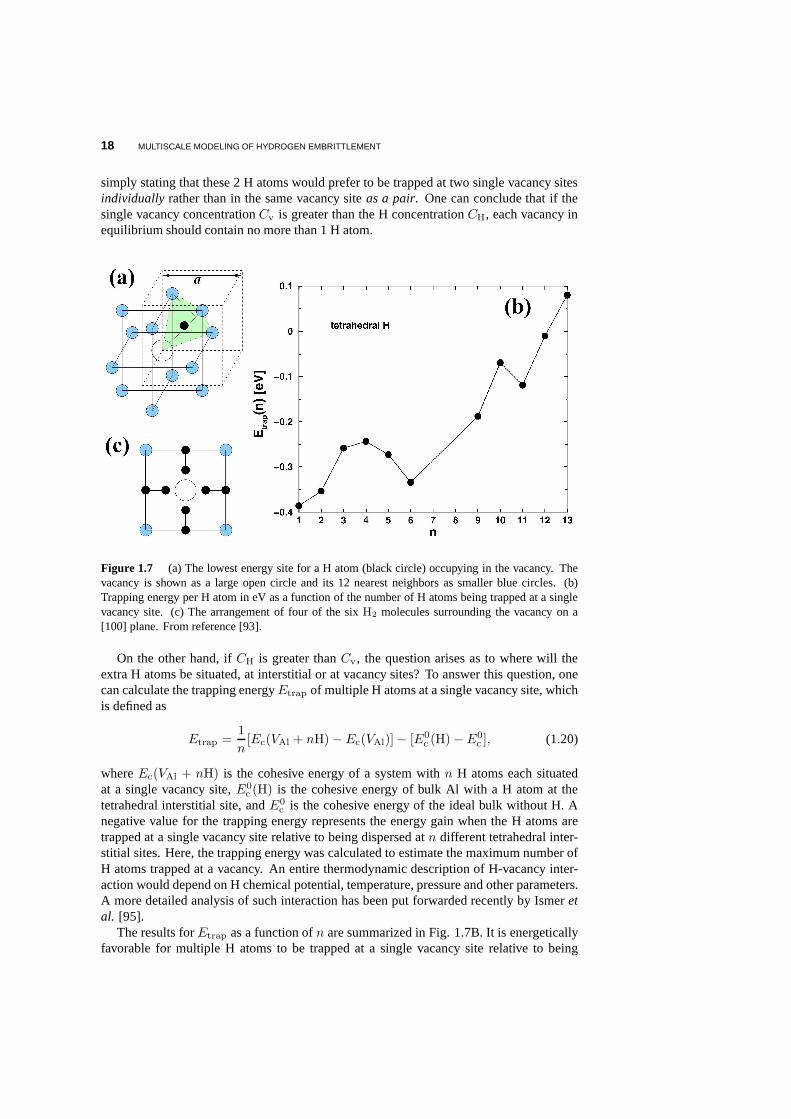
simply stating that these 2 H atoms would prefer to be trappedat two single vacancy sitesindividually rather than in the same vacancy siteas a pair. One can conclude that if thesingle vacancy concentrationCv is greater than the H concentrationCH, each vacancy inequilibrium should contain no more than 1 H atom.
Figure 1.7 (a) The lowest energy site for a H atom (black circle) occupying in the vacancy. Thevacancy is shown as a large open circle and its 12 nearest neighbors as smaller blue circles. (b)Trapping energy per H atom in eV as a function of the number of Hatoms being trapped at a singlevacancy site. (c) The arrangement of four of the sixH2 molecules surrounding the vacancy on a[100] plane. From reference [93].
On the other hand, ifCH is greater thanCv, the question arises as to where will theextra H atoms be situated, at interstitial or at vacancy sites? To answer this question, onecan calculate the trapping energyEtrap of multiple H atoms at a single vacancy site, whichis defined as
Etrap =1
n[Ec(VAl + nH)− Ec(VAl)]− [E0
c (H)− E0c ], (1.20)
whereEc(VAl + nH) is the cohesive energy of a system withn H atoms each situatedat a single vacancy site,E0
c (H) is the cohesive energy of bulk Al with a H atom at thetetrahedral interstitial site, andE0
c is the cohesive energy of the ideal bulk without H. Anegative value for the trapping energy represents the energy gain when the H atoms aretrapped at a single vacancy site relative to being dispersedatn different tetrahedral inter-stitial sites. Here, the trapping energy was calculated to estimate the maximum number ofH atoms trapped at a vacancy. An entire thermodynamic description of H-vacancy inter-action would depend on H chemical potential, temperature, pressure and other parameters.A more detailed analysis of such interaction has been put forwarded recently by Ismeretal. [95].
The results forEtrap as a function ofn are summarized in Fig. 1.7B. It is energeticallyfavorable for multiple H atoms to be trapped at a single vacancy site relative to being
MULTISCALE MODELING OF HYDROGEN EMBRITTLEMENT 19
dispersed at interstitial sites as individual atoms. In fact, up to twelve H atoms can betrapped at a single vacancy in Al. The atomic arrangement of the 12 H atoms trapped ata single vacancy is indicated in Fig. 1.7C. The ordered arrangement of the H atoms isnecessary to minimize the electrostatic energy. Due to the trapping effect, vacancies canlead to a significant reduction in apparent lattice diffusivity of H in Al, causing a strongcomposition dependence and non-Arrhenius behavior of the effective diffusion coefficient[94].
To check the possibility of H-induced vacancy clustering, anumber of relevant config-urations have been examined including (i) two vacancies, each with 1 H atom, forming aNN di-vacancy with 2 H atoms trapped; (ii)n vacancies, each with 2 H atoms, forming acomplex of NN multi-vacancies with 2n H atoms trapped, forn = 2 and 3. The results aresummarized by using the notation of chemical reactions as
(i) : 2VAlH → (VAl)2H2 − 0.21eV,
(ii) : nVAlH2 → (VAl)nH2n + n0.29eV(1.21)
where the last number in each equation represents the reaction enthalpy. A positive valueof enthalpy means the reaction is exothermic, that is, the process from left to right is ener-getically favorable. Consistent with the previous discussion, the reaction (i) is unfavorable(endothermic) because the effect of a single H atom on the covalent or metallic bondingof the NN Al atoms around the vacancy site is small and localized. On the other hand,reaction (ii) is favorable forn = 2 and 3, because theH2 units can attract more conduc-tion electrons from the nearby Al atoms, weakening the bonding among the NN Al atoms,which in turn drives the formation of multi-vacancies. The large energy gain in formingthe tri-vacancy (n = 3) is of particular interest. First, it is consistent with the experimen-tal observation that the single vacancy defects occupied byH atoms can coalesce to formplatelets on111 planes of Al. Although the calculations primarily concern the formationof the tri-vacancy, it is likely that even larger vacancy clusters can also be formed based onthe same mechanism. Second, these vacancy clusters can serve as embryos of cracks andmicrovoids with local H concentrations much higher than theaverage bulk value.
In general, the fracture surface is along the active slip planes where shear localizationoccurs. For fcc metals, the slip planes are the111 planes. In many cases, microvoidsopen up along these active slip planes in front of the crack tip; these microvoids can openand close in response to the local stress. Fracture occurs when these microcracks arejoined to the crack tip, upon reaching the critical stress. The H-enriched microvoids maybe created along the slip planes by the coalescence of vacancies with trapped H. Thesemicrovoids can be formedonly in the presence of H, which produces an additional sourceof microcracks necessary for the H embrittlement. On the other hand, the apparent latticemobility of H atoms is also enhanced since multiple H atoms may be trapped at a singlevacancy. All these vacancy-based mechanisms contribute tothe H embrittlement as theyincrease the rate of crack growth. Finally, the significant Htrapping at vacancies providesa scenario by which drastic increase of local H concentration may occur without improba-ble accumulation of H at bulk interstitial sites. This new feature resolves the longstandingproblem of how a sufficiently high H concentration can be realized to induce H embrittle-ment in materials such as Al, where the equilibrium H concentration in bulk is extremelylow.
20 MULTISCALE MODELING OF HYDROGEN EMBRITTLEMENT
1.3.4 Hydrogen Diffusion
H diffusion in metals plays an important role in H embrittlement. For example, it is ob-served experimentally that HELP occurs only when the thermal diffusion of H in the latticeis fast enough to follow the motion of dislocations [1]. In addition to their trapping of H,dislocations and grain boundaries are believed to provide short-circuit paths for acceler-ated diffusion. Dislocations and grain boundaries could act as fast paths for diffusingatoms whose mobility can be orders of magnitude higher than in bulk diffusion and thisphenomenon is often referred as “pipe diffusion”. Furthermore, H diffusion at the cracktip under stress is central to H-assisted cracking. Therefore, it is of great importance todetermine H diffusion energy barriers in extended defects.To this end, we have employedQM/MM approaches to calculate H diffusion energy barriers along dislocations and grainboundaries in Fe, Al, and Mg [53, 76, 77]. Being important by themselves, these energybarriers could also be incorporated in kinetic Monte Carlo or other models for sequentialmultiscale modeling of H embrittlement in metals.
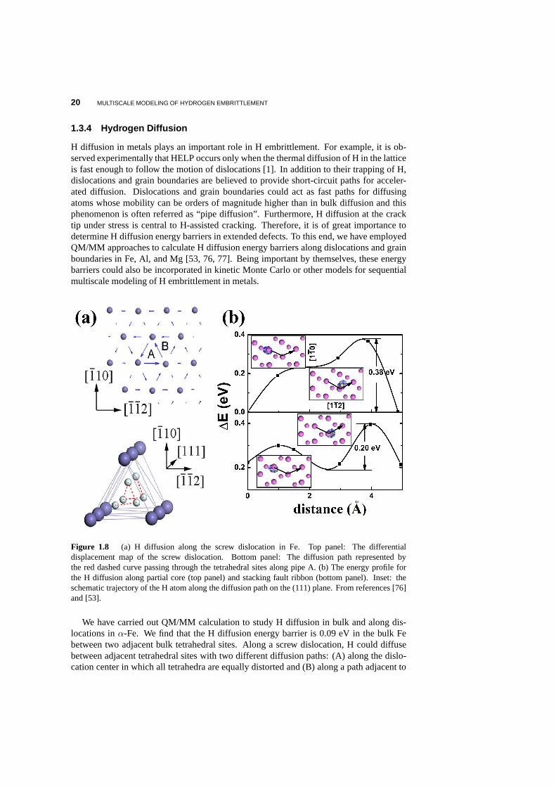
Figure 1.8 (a) H diffusion along the screw dislocation in Fe. Top panel:The differentialdisplacement map of the screw dislocation. Bottom panel: The diffusion path represented bythe red dashed curve passing through the tetrahedral sites along pipe A. (b) The energy profile forthe H diffusion along partial core (top panel) and stacking fault ribbon (bottom panel). Inset: theschematic trajectory of the H atom along the diffusion path on the (111) plane. From references [76]and [53].
We have carried out QM/MM calculation to study H diffusion inbulk and along dis-locations inα-Fe. We find that the H diffusion energy barrier is 0.09 eV in the bulk Febetween two adjacent bulk tetrahedral sites. Along a screw dislocation, H could diffusebetween adjacent tetrahedral sites with two different diffusion paths: (A) along the dislo-cation center in which all tetrahedra are equally distortedand (B) along a path adjacent to
SUMMARY AND OUTLOOK 21
the dislocation center in which the distortions are the not the same, as shown in Fig. 1.8A.The simulation results show that the diffusion energy barrier is 0.035 eV along the path Aand 0.063 eV along the path B [76]; both values are smaller than that in the bulk. SimilarQM/MM calculations have been performed in Al, and we find thatthe energy barriers are0.26 eV, 0.38 eV, and 0.20 eV for H diffusion along grain boundaries, partial dislocationcores, and the stacking fault ribbon, respectively [53]. Along the same crystallographicdirections, the corresponding diffusion barriers in the crystalline bulk lattice are 0.40 eV,0.32 eV, and 0.32 eV, respectively. Based on the diffusion energy barriers, one can estimatethe H diffusivity
D = νl2 exp[−∆E/kBT ], (1.22)
whereν is the attempt frequency,l is the hopping length, and∆E is the diffusion energybarrier. At room temperature, there are two (one) orders of magnitude increase of diffu-sivity for H diffusion in Al (Fe) dislocations comparing to the bulk diffusivity. Therefore,dislocations in Al and Fe indeed can sever as fast pipes for H diffusion. The consequenceof these results on H embrittlement is being pursued in our group.
However, we find that the basal dislocations of Mg are not easier paths for H diffusion[77]. In bulk Mg, the H diffusion consists of two types: (1) between the adjacent tetrahedralsites surrounded by octahedral sites; (2) between the octahedral site and its neighboringtetrahedral site. The long-range diffusion requires a combination of the two types. Theenergy barriers of case (1) and (2) are 0.04 eV and 0.21 eV respectively. The highervalue 0.21 eV is the actual energy barrier for the long-rangediffusion. These values areconsistent with experimental results [96, 97]. Along the partial dislocation core of Mg,the QM/MM results show that the barriers slightly increase to 0.22 eV and 0.26 eV for thescrew and edge dislocation respectively. And in the stacking fault ribbon the correspondingbarriers become 0.25 eV and 0.47 eV. Therefore, the energy barrier for H diffusion in Mgdislocations is actually greater than that in the crystalline lattice, in contrast to the cases inAl and Fe. More investigations are desired to understand theramifications of these resultsin H embrittlement of Mg. Finally, we have also examined H diffusion at the crack tip ofAl and find that H can diffuse with relative ease on the crack surfaces with lower energybarriers than those in the bulk; the H atoms on the fracture surfaces can even recombineinto H2 molecules before re-dissociation at the fresh crack front surface to attack Al-Albonds [85].
1.4 Summary and Outlook
Based on the experimental observations and the simulation results, we can tentatively iden-tify the following key processes leading to H embrittlementof metals: (a) Application ofexternal stress produces local concentration of tensile stress in the vicinity of cracks, whichattracts H since H prefers to stay in slightly enlarged interstitial sites. H impurities can alsobe adsorbed at the crack surfaces near the crack tip; the relative ease of H diffusion onthe crack surfaces may provide a rapid means of transportingH to the fresh crack front.(b) H can also segregate at vacancies inside the material which may lead to microvoidswith high local H concentrations; the microvoids could merge to form cracks under stress.(c) The segregated H impurities at the crack tip can facilitate dislocation generation anddeformation twining and enhance dislocation mobility, which will lead to extensive plas-tic deformation in front of the crack. The highly deformed region ahead of the crack tipbecomes the “weakest link” where fracture takes place. (d) The highly deformed and dis-ordered region along with the localization of slip due to theinhibition of cross-slip, allows
22 MULTISCALE MODELING OF HYDROGEN EMBRITTLEMENT
the crack to propagate at lower stress levels, prior to general yielding away from the cracktip. These processes are not likely to be the only mechanism operating in H embrittlement[70], but are the most relevant processes in line with our multiscale modeling results onaluminum. The similar mechanism could be operative in othermetals as well, but it shouldbe further validated to be certain.
Multiscale modeling will continue to be important for understanding H embrittlementphenomena in metals. One area of particular importance and challenge is to model stresscorrosion cracking under realistic conditions and in aqueous environment. The molecularstructure of solid-liquid interface, pH of electrolyte, surface charge, field and electrochem-ical potential are all relevant parameters that need to be included in the modeling.Ab initiomethods for modeling the charged solid/liquid interface atthe atomic level are starting toappear [98, 99, 100, 101]. An interesting future direction is to incorporate this type ofabinitio modeling into QCDFT framework so that the chemo-mechanicaland electrochemicalprocesses important to the stress corrosion cracking can becaptured.
We acknowledge the collaborators who have contributed to our understanding of Hembrittlement in metals and the development of the multiscale methodologies presented inthis chapter. The related research was supported primarilyby NSF-PREM program, DoE-SciDAC program and the Office of Naval Research (ONR). We are particularly grateful toKenny Lipkowitz for his encouragement and support.
REFERENCES
1. Myers SM, Baskes MI, Birnbaum HK, Corbett JW, DeLeo GG, Estreicher SK, Haller EE, JenaP, Johnson NM, Kirchheim R, Pearton SJ, Stavola MJ. Hydrogeninteractions with defects incrystalline solids. Rev. Mod. Phys. 1992;64:559-617.
2. Oriani RA. Hydrogen embrittlement of steels. Ann. Rev. Mater. Sci. 1978;8:327-357.
3. Westlake DG. A generalized model for hydrogen embrittlement. Trans. ASM 1969;62:1000-1006.
4. Gahr S, Grossbeck ML, Birnbaum HK. Hydrogen embrittlement of Nb I - macroscopic behaviorat low temperatures. Acta Metall. 1977;25:125-134.
5. Shi D, Robertson IM, Birnbaum HK. Hydrogen embrittlementof α-titanium: in situ TEM stud-ies. Acta Metall. 1988;36:111-124.
6. Beachem CD. A new model for hydrogen-assisted cracking (hydrogen embrittlement). Metall.Trans. 1972;3:437-451.
7. Sofronis P, Robertson IM. TEM observations and micromechanical/continuum models for theeffect of hydrogen on the mechanical behavior of metals. Philos. Mag. A 2002;82:3405-3413.
8. Eastman J, Matsumoto T, Narita N, Heubaum N, Birnbaum HK. Hydrogen effects in nickelembrittlement or enhanced ductility? In: Bernstein IM, Thompson AW, editors. Hydrogen inmetals. New York: AIME;1981. p 397-399.
9. Matsumoto T, Eastman J, Birnbaum HK. Direct observationsof enhanced dislocation mobilitydue to hydrogen. Scripta Metall. 1981;15:1033-1037.
10. Oriani RA, Josephic PH. Equilibrium aspects of hydrogen-induced cracking of steels. ActaMetall, 1974;22:1065-1074.
11. Oriani RA, Josephic PH. Equilibrium and kinetic studiesof the hydrogen-assisted cracking ofsteels. Acta Metall, 1977;25:979-988.
12. Steigerwald EA, Schaller FW, Troiano AR. The role of stress in hydrogen induced delayedfailure. Trans. Metall Soc. AIME, 1960;218:832-841.
SUMMARY AND OUTLOOK 23
13. Phillips R. Crystals, defects and microstructures - modeling across scales. Cambridge(UK):Cambridge University Press; 2001.
14. Lu G, Kaxiras E. Overview of Multiscale Simulations of Materials. In: Rieth M, SchommersW, editors. Handbook of Theoretical and Computational Nanotechnology. Stevenson Ranch:American Scientific; 2004. Chap. 22.
15. Kaxiras E, Yip S. Modeling and simulation of solids. Curr. Opin. Solid State Mater. Sci.1998;3:523-525 and accompanying articles.
16. Diaz de la Rubia T, Bulatov VV. Materials research by means of multiscale computer simulation.MRS Bull. 2001;26:169-175 and accompanying articles.
17. Yip S. Synergistic science. Nature Mater. 2003;2:3-5.
18. Hohenberg P, Kohn W. Inhomogeneous electron gas. Phys. Rev. 1964;136:B864-B871.
19. Kohn W, Sham LJ. Self-consistent equations including exchange and correlation effects. Phys.Rev. 1965;140:A1133-A1138.
20. Abraham FF, Walkup R, Gao H, Duchaineau M, de la Rubia T, Seager M. Simulating materialsfailure by using up to one billion atoms and the world’s fastest computer: work-hardening. Proc.Natl. Acad. Sci. USA, 2002;99:5777-5782.
21. Hughes TJR. The finite element method. Englewood Cliffs(NJ): Prentice-Hall; 1987.
22. Peierls R. The size of a dislocation. Proc. Phys. Soc. London 1940;52:34-37.
23. Nabarro FRN. Dislocations in a simple cubic lattice. Proc. Phys. Soc. London 1947;59:256-272.
24. Joos B, Ren Q, and Duesbery MS. Peierls-Nabarro model of dislocations in silicon with gener-alized stacking-fault restoring forces. Phys. Rev. B 1994;50:5890-5898.
25. Joos B, Duesbery MS. The Peierls Stress of Dislocations:An Analytic Formula. Phys. Rev.Lett. 1997;78:266-269.
26. Juan Y, and Kaxiras E. Generalized stacking fault energysurfaces and dislocation properties ofsilicon: a first-principles theoretical study. Philos. Mag. A 1996;74:1367-1384.
27. Hartford J, von Sydow B, Wahnstrom G, Lundqvist BI. Peierls barriers and stresses for edgedislocations in Pd and Al calculated from first principles. Phys. Rev. B 1998;58:2487-2496.
28. von Sydow B, Hartford J, Washnstrom G. Atomistic simulations and Peierls-Nabarro analysisof the Shockley partial dislocations in palladium. Comput.Mater. Sci. 1999;15:367-379.
29. Medvedeva NI, Mryasov ON, Gornostyrev YN, Novikov DL, Freeman AJ. First-principles total-energy calculations for planar shear and cleavage decohesion processes in B2-ordered NiAl andFeAl. Phys. Rev. B 1996;54:13506-13514.
30. Mryasov ON, Gornostyrev YN, Freeman AJ. Generalized stacking-fault energetics and dislo-cation properties: Compact versus spread unit-dislocation structures in TiAl and CuAu. Phys.Rev. B 1998;58:11927-11932.
31. Bulatov VV, Kaxiras E. Semidiscrete Variational Peierls Framework for Dislocation Core Prop-erties. Phys. Rev. Lett. 1997;78:4221-4224.
32. Lu, G, The Peierls-Nabarro Model of Dislocations: A Venerable Theory And Its Current Devel-opment. S. Yip (ed.), Handbook of Materials Modeling. Volume I: Methods and Models, 2005Springer (Netherlands).
33. Lu G, Kioussis N, Bulatov VV, Kaxiras E. Generalized-stacking-fault energy surface and dislo-cation properties of aluminum. Phys. Rev. B 2000;62:3099-3108.
34. Lu G, Zhang Q, Kioussis N, Kaxiras E. Hydrogen-Enhanced Local Plasticity in Aluminum: AnAb Initio Study. Phys. Rev. Lett. 2001;87:095501.
35. Lu G, Kaxiras E. Can Vacancies Lubricate Dislocation Motion in Aluminum? Phys. Rev. Lett.2002;89:105501.
24 MULTISCALE MODELING OF HYDROGEN EMBRITTLEMENT
36. Lu G, Bulatov VV, Kioussis N. Dislocation constriction and cross-slip: An ab initio study. Phys.Rev. B 2002;66:144103.
37. Vitek V. Intrinsic stacking faults in body-centered cubic crystals. Philos. Mag. 1968;18:773-786.
38. Eshelby JD. Edge Dislocations in Anisotropic Materials. Philos. Mag. 1949;40:903-912.
39. Hirth JP, Lothe J. Theory of Dislocations. 2nd ed. New York:Wiley; 1992.
40. Bernstein N, Kermode JR, Csanyi G. Hybrid atomistic simulation methods for materials sys-tems. Rep. Prog. Phys. 2009;72:026501.
41. Lin H, Truhlar DG. QM/MM: what have we learned, where are we, and where do we go fromhere? Theor. Chem. Acc. 2007;117:185-199.
42. Zhang X, Zhao Y, Lu G. Recent development in quantum mechanics/molecular mechanics mod-eling for materials. Int. J. Multiscale Comput. Eng. 2012;10:65-82.
43. Antes I, Thiel W. On the treatment of link atoms in hybrid methods. In: Gao J, Thompson MA,editors. Hybrid Quantum Mechanical and Molecular Mechanical Methods Proc. ACS Symp.Ser. Washington DC: ACS; 1998. 712:50-65.
44. Gao J, Truhlar DG. Quantum mechanical methods for enzymekinetics. Annu. Rev. Phys. Chem.2002;53:467-505.
45. Zhang X, Lu G, Curtin WA. Multiscale quantum/atomistic coupling using constrained densityfunctional theory. Phys. Rev. B 2013;87:054113.
46. Huang P, Carter EA. Advances in Correlated Electronic Structure Methods for Solids, Surfaces,and Nanostructures. Annu. Rev. Phys. Chem. 2008;59:261-290.
47. Nair AK, Warner DH, Hennig RG, Curtin WA. Coupling quantum and continuum scales topredict crack tip dislocation nucleation. Scr. Mater. 2010;63:1212-1215.
48. Leyson GP, Curtin WA, Hector LG Jr, Woodward CF. Quantitative prediction of solute strength-ening in aluminium alloys. Nature Mater. 2010;9:750-755.
49. Woodward C, Rao SI. Flexible Ab Initio Boundary Conditions: Simulating Isolated Dislocationsin bcc Mo and Ta. Phys. Rev. Lett. 2002;88:216402.
50. Choly N, Lu G, E W, Kaxiras E. Multiscale simulations in simple metals: A density-functional-based methodology. Phys. Rev. B 2005;71:094101.
51. Zhang X, Lu G. Quantum mechanics/molecular mechanics methodology for metals based onorbital-free density functional theory. Phys. Rev. B 2007;76:245111.
52. Zhang X, Wang CY, Lu G. Electronic structure analysis of self-consistent embedding theory forquantum/molecular mechanics simulations. Phys. Rev. B 2008;78:235119.
53. Zhang X, Peng Q, Lu G. Self-consistent embedding quantummechanics/molecular mechanicsmethod with applications to metals. Phys. Rev. B 2010;82:134120.
54. Daw MS, Baskes MI. Embedded-Atom method: Derivation andapplication to impurities, sur-faces, and other defects in metals. Phys. Rev. B 1984;29:6443-6453.
55. Zhang X, Lu G. Quantum mechanics/molecular mechanics methodology based on constraineddensity functional theory. 2012; submitted.
56. Garcia Gonzalez P, Alvarellos JE, Chacon E. Nonlocal kinetic-energy-density functionals. Phys.Rev. B 1996;53:9509-9512.
57. Wang LW, Teter MP. Kinetic-energy functional of the electron-density. Phys. Rev. B1992;45:13196-13220.
58. Wang YA, Govind N, Carter EA. Orbital-free kinetic-energy density functionals with a density-dependent kernel. Phys. Rev. B 1999;60:16350-16358.
59. Liu Y, Lu G, Chen ZZ, Kioussis N. An improved QM/MM approach for metals. ModellingSimul. Mater. Sci. Eng. 2007;15:275-284.
SUMMARY AND OUTLOOK 25
60. Tadmor EB, Ortiz M, Phillips R. Quasi-continuum analysis of defects in solids. Philos. Mag. A1996;73:1529-1563.
61. Lu G, Tadmor EB, Kaxiras E. From electrons to finite elements: a concurrent multiscale ap-proach for metals. Phys. Rev. B 2006;73:024108.
62. Peng Q, Zhang X, Hung L, Carter EA, Lu G. Quantum simulation of materials at micron scalesand beyond. Phys. Rev. B 2008;78:054118.
63. Peng Q, Lu G. A comparative study of fracture in Al: Quantum mechanical vs. empirical atom-istic description. J. Mech. Phys. Solids 2011;59:775-786.
64. Birnbaum HK. Mechanism of hydrogen related fracture of metals. In: Moody NR, ThompsonAW, editors. Hydrogen Effects on Material Behavior. Warrendale: TMS; 1990. p 629-660.
65. Tabata T, Birnbaum HK. Direct observations of the effectof hydrogen on the behavior of dislo-cations in iron. Scripta Metall. 1983;17:947-950.
66. Tabata T, Birnbaum HK. Direct observations of hydrogen enhanced crack propagation in iron.Scripta Metall. 1984;18:231-236.
67. Robertson IM, Birnbaum HK. An HVEM study of hydrogen effects on the deformation andfracture of nickel. Acta Metall. 1986;34:353-366.
68. Bond GM, Robertson IM, Birnbaum HK. The influence of hydrogen on deformation and frac-ture processes in high-strength aluminum alloys. Acta Metall. 1987;35:2289-2296.
69. Bond GM, Robertson IM, and Birnbaum HK. Effects of hydrogen on deformation and fractureprocesses in high-purity aluminum. Acta Metall. 1988;36:2193-2197.
70. Birnbaum HK, Sofronis P. Hydrogen-enhanced localized plasticity - a mechanism for hydrogen-related fracture. Mater. Sci. Eng. A 1994;176:191-202.
71. Ulmer DG, Altstetter CJ. Hydrogen-induced strain localization and failure of austeniticstainless-steels at high hydrogen concentrations. Acta Metall. Mater. 1991;39:1237-1248.
72. Tang X, Thompson AW. Hydrogen effects on slip character and ductility in Ni-Co alloys. Mater.Sci. Eng. A 1994;186:113-119.
73. Walston WS, Bernstein IM, Thompson AW. The effect of internal hydrogen on a single-crystalnickel-base superalloy. Metall. Trans. A 1992;23:1313-1322.
74. He J, Fukuyama S, Yokogawa K, Kimura A. Effect of hydrogenon deformation structure ofinconel-718. Mater. Trans. JIM 1994;35:689-694.
75. McInteer WA, Thompson AW, Bernstein IM. The effect of hydrogen on the slip character ofnickel. Acta Metall. 1980;28:887-894.
76. Zhao Y, Lu G. QM/MM study of dislocation-hydrogen/helium interactions inα-Fe. ModellingSimul. Mater. Sci. Eng. 2011;19:065004.
77. Zhao Y, Lu G. H in Mg: energetics of decohesion, slip, twinning and diffusion. 2012; submitted.
78. Lu G, Orlikowski D, Park I, Politano O, Kaxiras E. Energetics of hydrogen impurities in alu-minum and their effect on mechanical properties. Phys. Rev.B 2002;65:064102.
79. Rice JR. Dislocation nucleation from a crack tip: an analysis based on the Peierls concept. J.Mech. Phys. Solids 1992;40:239-271.
80. Daw MS, Baskes MI. Application of the embedded atom method to hydrogen embrittlement. In:Latanision RM, R. Jones R, editors. Chemistry and Physics ofFracture. Netherlands: MartinusNijhoff Publishers; 1987. p 196-218.
81. Sofronis P, Birnbaum HK. Mechanics of the Hydrogen-Dislocation-Impurity Interactions: PartI-Increasing Shear Modulus. J. Mech. Phys. Solids 1995;43:49-90.
82. Spitzig WA, Keh AS. The effect of orientation and temperature on the plastic flow properties ofiron single crystals. Acta. Metall. 1970;18:611-622.
26 MULTISCALE MODELING OF HYDROGEN EMBRITTLEMENT
83. Lynch SP. Metallographic and Fractographic techniquesfor characterising and understandinghydrogen-assisted cracking of metals. In: Gangloff R, Somerday B, editors. Gaseous hydrogenembrittlement of materials in energy technologies. Cambridge: Woodhead; 2012. p 274-346.
84. Farkas D, Duranduru M, Curtin WA, Ribbens C. Multiple-dislocation emission from the cracktip in the ductile fracture of Al. Philos. Mag. A 2001;81:1241-1255.
85. Sun Y, Peng Q, Lu G. Hydrogen assisted cracking: a QCDFT study of Aluminum crack-tip.2012; submitted.
86. Apostol F and Mishin Y. Hydrogen effect on shearing and cleavage of Al: A first-principlesstudy. Phys. Rev. B 2011;84:104103.
87. Gunnarsson O, Hjelmberg H, Lundqvist BI. Binding energies for different adsorption sites ofhydrogen on simple metals. Phys. Rev. Lett. 1976;37:292-295.
88. Waghmare UV, Kaxiras E, and Duesbery MS. Modeling Brittle and Ductile Behavior of Solidsfrom First-Principles Calculations. Phys. Status Solidi B2000;217:545-564.
89. Fukai Y, Okuma N. Formation of Superabundant Vacancies in Pd Hydride under High HydrogenPressures. Phys. Rev. Lett. 1994;73:1640-1643.
90. Fukai Y. Superabundant Vacancies Formed in Metal Hydrogen Alloys. Phys. Scr. 2003;T103:11-14.
91. Tateyama Y, Ohno T. Stability and clusterization of hydrogen-vacancy complexes in Fe: An abinitio study. Phys. Rev. B 2003;67:174105.
92. Birnbaum HK, Buckley C, Zeides F, Sirois E, Rozenak P, Spooner S, Lin JS. Hydrogen inaluminum. J. Alloy. Compd. 1997;253-254:260-264.
93. Lu G, Kaxiras E. Hydrogen Embrittlement of Aluminum: TheCrucial Role of Vacancies. Phys.Rev. Lett. 2005;94:155501.
94. Gunaydin H, Barabash SV, Houk KN, Ozolins V. First-Principles Theory of Hydrogen Diffusionin Aluminum. Phys. Rev. Lett. 2008;101:075901.
95. Ismer L, Park MS, Janotti A, Van de Walle CG. Interactionsbetween hydrogen impurities andvacancies in Mg and Al: A comparative analysis based on density functional theory. Phys. Rev.B 2009;80:184110.
96. Tsuru T, Latanision RM. Grain boundary transport of hydrogen in nickel. Scr. Metall.1982;16:575-578.
97. Nishimura C, Komaki M, Amano M. Hydrogen permeation through magnesium. J. AlloysCompd. 1999;293-295:329-333.
98. Taylor CD, Sally A. Wasileski SA, Filhol JS, Neurock M. First principles reaction modeling ofthe electrochemical interface: Consideration and calculation of a tunable surface potential fromatomic and electronic structure. Phys. Rev. B 2006;73:165402.
99. Filhol JS, Neurock M. Elucidation of the Electrochemical Activation of Water over Pd by FirstPrinciples. Angew. Chem. Int. Ed. 2006;45:402-406.
100. Schnur S, and Grob A. Properties of metal-water interfaces studied from first principles. NewJ. Phys. 2009;11:125003.
101. Rossmeisl J, Skulason E, Bjorketun ME, Tripkovic V, Norskov JK. Modeling the electrifiedsolid-liquid interface. Chem. Phys. Lett. 2008;466:68-71.


