My Tessellation Has Cracks! (and solutions to other tessellation related problems)
Bryan Dudash Developer Technology, NVIDIA
Agenda
● Super-Quick Tessellation Review ● How cracks/holes are born ● Specific examples
● PN Triangles cracking ● Displacement map cracking
● Other Tessellation Issues ● Debugging Techniques ● Ptex
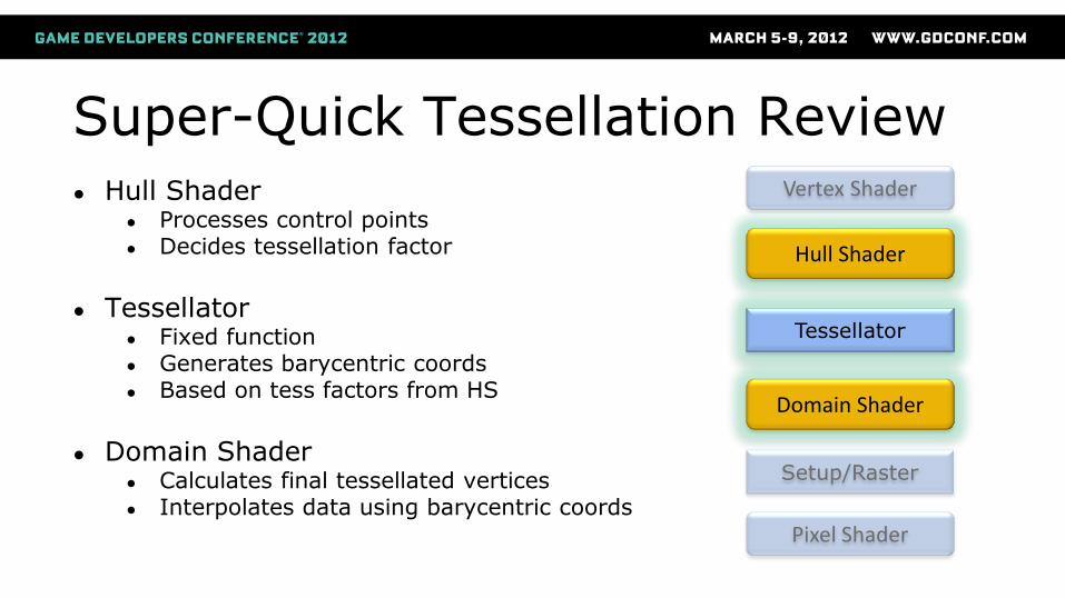
Super-Quick Tessellation Review ● Hull Shader
● Processes control points ● Decides tessellation factor
● Tessellator
● Fixed function ● Generates barycentric coords ● Based on tess factors from HS
● Domain Shader
● Calculates final tessellated vertices ● Interpolates data using barycentric coords
Domain Shader
Hull Shader
Tessellator
Vertex Shader
Setup/Raster
Pixel Shader
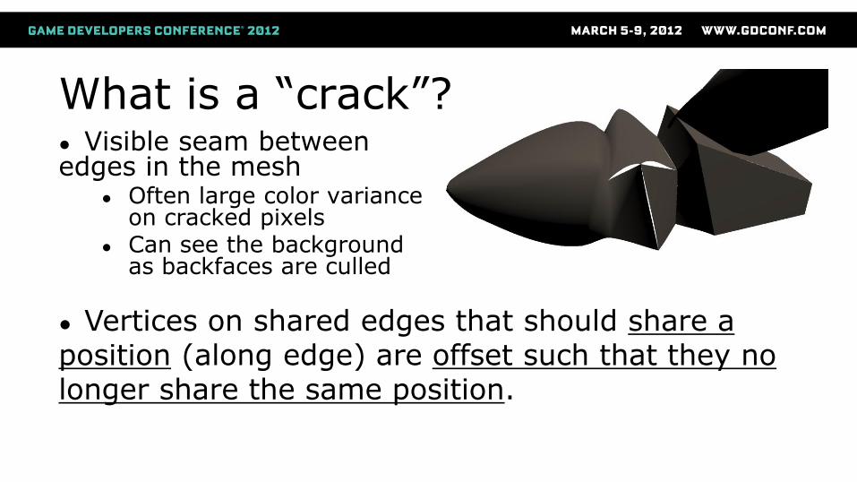
What is a “crack”? ● Visible seam between edges in the mesh
● Often large color variance on cracked pixels
● Can see the background as backfaces are culled
● Vertices on shared edges that should share a position (along edge) are offset such that they no longer share the same position.
Holes: The other “crack”
● A “hole” is when shared control vertices diverge position ● Can think of this as multiple “cracks”
● Can result in much larger seams
● Same avoidance methods as cracks
● Can cause holes without tessellation!
● Different vertex offsets in VS per SV_PrimitiveID
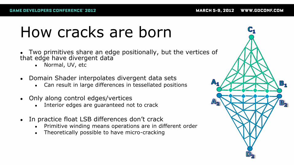
How cracks are born ● Two primitives share an edge positionally, but the vertices of that edge have divergent data
● Normal, UV, etc
● Domain Shader interpolates divergent data sets ● Can result in large differences in tessellated positions
● Only along control edges/vertices ● Interior edges are guaranteed not to crack
● In practice float LSB differences don’t crack
● Primitive winding means operations are in different order ● Theoretically possible to have micro-cracking
b
c a
i h
d
e f
g
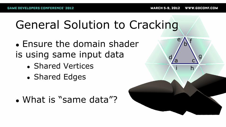
General Solution to Cracking ● Ensure the domain shader is using same input data
● Shared Vertices
● Shared Edges
● What is “same data”?
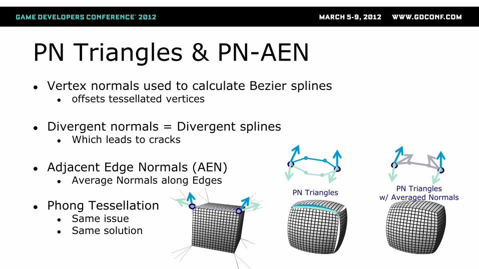
PN Triangles & PN-AEN
● Vertex normals used to calculate Bezier splines ● offsets tessellated vertices
● Divergent normals = Divergent splines
● Which leads to cracks
● Adjacent Edge Normals (AEN)
● Average Normals along Edges
● Phong Tessellation ● Same issue ● Same solution
PN Triangles PN Triangles
w/ Averaged Normals
b
c a
i h
d
e f
g
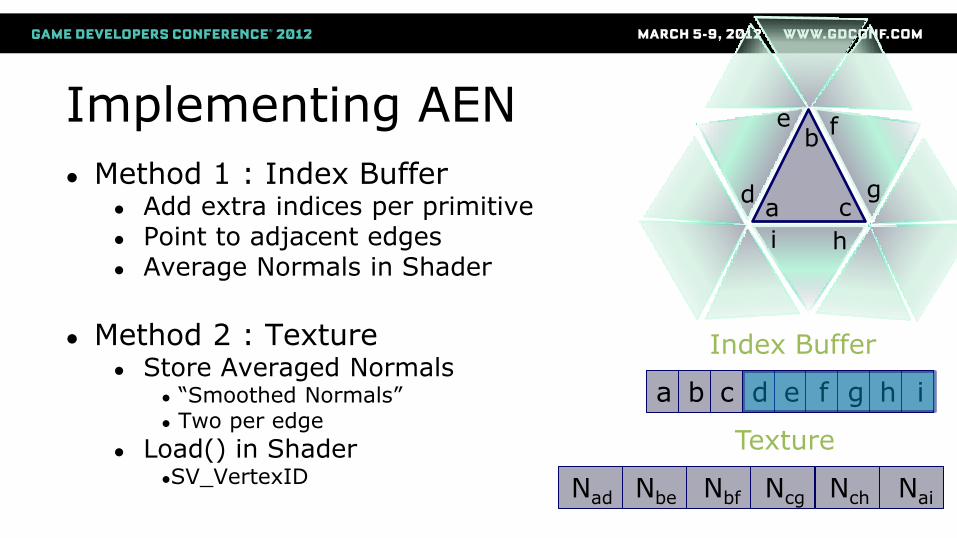
Implementing AEN
● Method 1 : Index Buffer ● Add extra indices per primitive ● Point to adjacent edges ● Average Normals in Shader
● Method 2 : Texture
● Store Averaged Normals ● “Smoothed Normals” ● Two per edge
● Load() in Shader ●SV_VertexID
Index Buffer
a b c d e f g h i
Texture
Nad Nbe Nbf Ncg Nch Nai
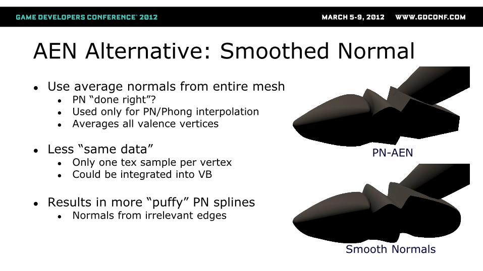
AEN Alternative: Smoothed Normal
● Use average normals from entire mesh ● PN “done right”? ● Used only for PN/Phong interpolation ● Averages all valence vertices
● Less “same data” ● Only one tex sample per vertex ● Could be integrated into VB
● Results in more “puffy” PN splines
● Normals from irrelevant edges
PN-AEN
Smooth Normals
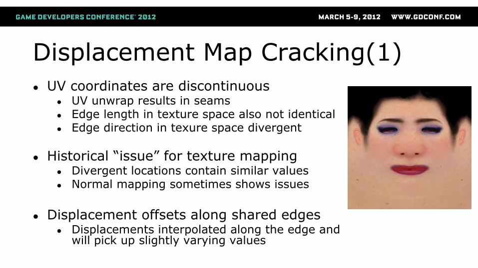
Displacement Map Cracking(1) ● UV coordinates are discontinuous
● UV unwrap results in seams ● Edge length in texture space also not identical ● Edge direction in texure space divergent
● Historical “issue” for texture mapping ● Divergent locations contain similar values ● Normal mapping sometimes shows issues
● Displacement offsets along shared edges
● Displacements interpolated along the edge and will pick up slightly varying values
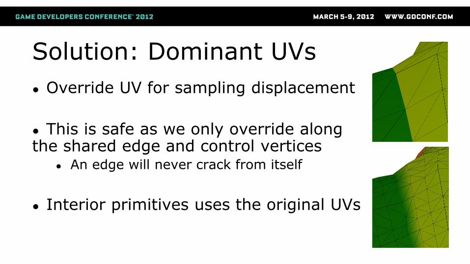
Solution: Dominant UVs
● Override UV for sampling displacement
● This is safe as we only override along the shared edge and control vertices
● An edge will never crack from itself
● Interior primitives uses the original UVs
b
c a
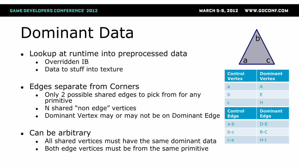
Dominant Data
● Lookup at runtime into preprocessed data ● Overridden IB ● Data to stuff into texture
● Edges separate from Corners
● Only 2 possible shared edges to pick from for any primitive
● N shared “non edge” vertices ● Dominant Vertex may or may not be on Dominant Edge
● Can be arbitrary
● All shared vertices must have the same dominant data ● Both edge vertices must be from the same primitive
Control Vertex
Dominant Vertex
a A
b E
c H
Control Edge
Dominant Edge
a-b D-E
b-c B-C
c-a H-I
J
E
A H I
Index Buffer
Texture
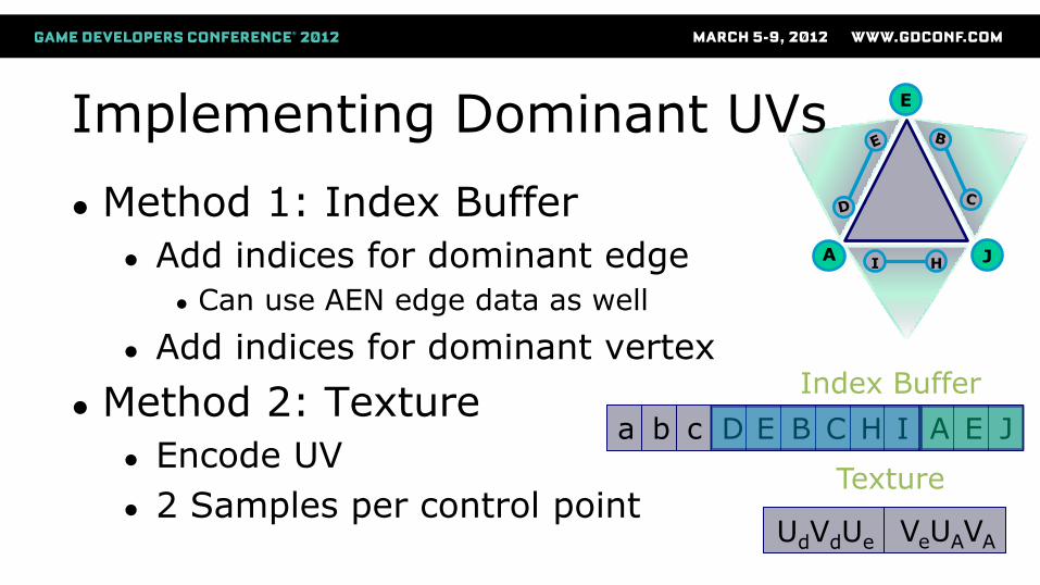
UdVdUe
Implementing Dominant UVs
● Method 1: Index Buffer
● Add indices for dominant edge
● Can use AEN edge data as well
● Add indices for dominant vertex
● Method 2: Texture
● Encode UV
● 2 Samples per control point
a b c D E B C H A E J I
VeUAVA
Dominant Data Generation ● CPU side pre-process
● Typically done as part of a build/cook process ● Can be done on mesh load as well
● Generate Packed Listing of shared position & edges ● List of indices at each shared position ● List of index tuple at each shared edge start
● Arbitrarily pick dominant data
● First entry in the list
● It really is that simple
Intra-material cracking
● Meshes in games often have multiple materials ● Submeshes render as separate draws ● With separate textures and UV spaces ● No access to neighbor info across seams
● Solutions
● If submeshes share a VB, then AEN style techniques can work ● Smooth normal/Dominant UV texture can encode data from
group of submeshes ● Pin displacement to 0 at edge
● May not look “right” ● Alternative is mesh rework.
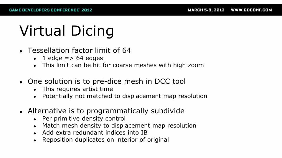
Virtual Dicing
● Tessellation factor limit of 64 ● 1 edge => 64 edges ● This limit can be hit for coarse meshes with high zoom
● One solution is to pre-dice mesh in DCC tool
● This requires artist time ● Potentially not matched to displacement map resolution
● Alternative is to programmatically subdivide ● Per primitive density control ● Match mesh density to displacement map resolution ● Add extra redundant indices into IB ● Reposition duplicates on interior of original
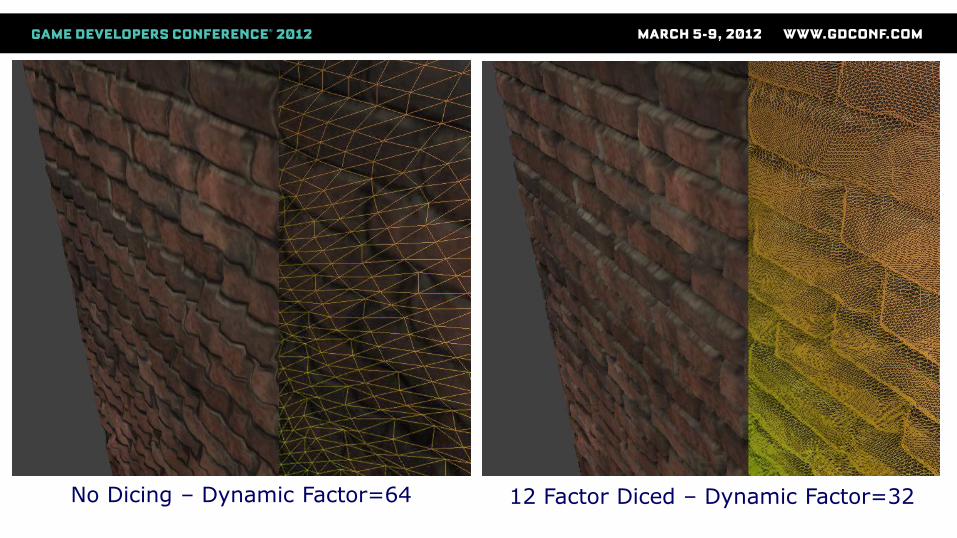
No Dicing – Dynamic Factor=64 12 Factor Diced – Dynamic Factor=32
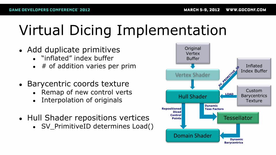
Virtual Dicing Implementation
● Add duplicate primitives ● “inflated” index buffer ● # of addition varies per prim
● Barycentric coords texture
● Remap of new control verts ● Interpolation of originals
● Hull Shader repositions vertices
● SV_PrimitiveID determines Load()
Domain Shader
Hull Shader
Tessellator
Custom Barycentrics
Texture
Inflated Index Buffer
Vertex Shader
Original Vertex Buffer
LOAD
Repositioned Diced
Control Points
Dynamic Tess Factors
Dynamic Barycentrics
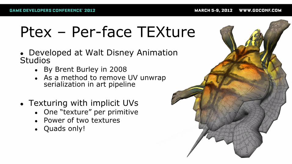
Ptex – Per-face TEXture
● Developed at Walt Disney Animation Studios
● By Brent Burley in 2008 ● As a method to remove UV unwrap
serialization in art pipeline
● Texturing with implicit UVs
● One “texture” per primitive ● Power of two textures ● Quads only!
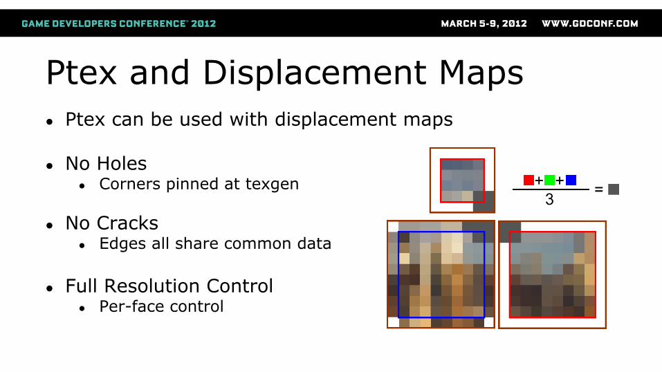
Ptex and Displacement Maps
● Ptex can be used with displacement maps
● No Holes ● Corners pinned at texgen
● No Cracks ● Edges all share common data
● Full Resolution Control
● Per-face control
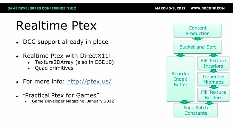
Realtime Ptex
● DCC support already in place
● Realtime Ptex with DirectX11! ● Texture2DArray (also in D3D10) ● Quad primitives
● For more info: http://ptex.us/
● “Practical Ptex for Games”
● Game Developer Magazine: January 2012
Content Production
Bucket and Sort
Generate Mipmaps
Fill Texture Interiors
Reorder Index Buffer
Fill Texture Borders
Pack Patch Constants
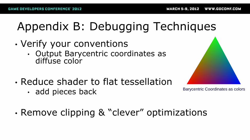
Appendix B: Debugging Techniques
• Verify your conventions • Output Barycentric coordinates as
diffuse color
• Reduce shader to flat tessellation
• add pieces back
• Remove clipping & “clever” optimizations
Barycentric Coordinates as colors
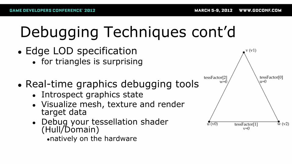
Debugging Techniques cont’d ● Edge LOD specification
● for triangles is surprising
● Real-time graphics debugging tools
● Introspect graphics state ● Visualize mesh, texture and render
target data ● Debug your tessellation shader
(Hull/Domain) ●natively on the hardware
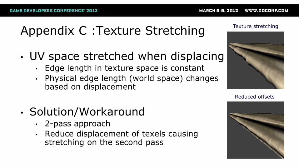
Appendix C :Texture Stretching
• UV space stretched when displacing • Edge length in texture space is constant
• Physical edge length (world space) changes based on displacement
• Solution/Workaround • 2-pass approach
• Reduce displacement of texels causing stretching on the second pass
Texture stretching
Reduced offsets