
31NASA IGES and
NASA-IGESNURBS-Only Standard
31.1 IntroductionPurpose • Scope • Background • NASA Support
32.2 Underlying Principles (the CFD Process)The CFD Analysis Process • The CFD Design Process • Problems with Pre-NASA-IGES Methods • CFD Design Utilizing NASA-IGES • CFD Design Utilizing the Supplied Database Information Format • General Information on Data Description
31.3 Best PracticesMultidisciplinary Data Exchange Standards • Summary of Entity Types and Recommended Usage • Case Studies • Other NASA-IGES Compatible Software
31.4 Research Issues and Summary
31.1 Introduction
31.1.1 Purpose
This chapter is intended to provide background on the NASA Geometry Data Exchange Specificationfor Computational Fluid Dynamics (NASA-IGES) [RP1338, 1994] and the NURBS-Only subset of NASA-IGES. This will elucidate the logic behind the standard. Documentation in this area will be referencedto provide additional sources of information for future reference. Sample NASA-IGES compatible soft-ware will also be discussed. This should facilitate the usage of the NASA-IGES protocol for rapid andaccurate data transfer, and should serve to promote the use of an accurate and unified geometry repre-sentation method for CFD research.
31.1.2 Scope
This chapter contains an updated synopsis of the NASA-IGES specification along with information onthe follow-on activities to the standard. This material has been divided into six sections. The first is thisintroductory section, which provides some background in this area. Section 31.2 relates the underlyingprinciples and the logic behind the standard and its application. Section 31.3 includes the recommendedbest practices for use while implementing the NASA-IGES standard. Section 31.4 notes future researchissues in this area. The fifth and sixth sections contain the references and bibliography for furtherinformation.
Austin L. Evans
David P. Miller
©1999 CRC Press LLC
31.1.3 Background
The geometry data received by NASA scientists for analysis and modification has been supplied in
©1999 CRC Press LLC
numerous formats that often require hundreds of hours of manipulation to achieve a format capable ofbeing utilized by analysis software. It has been estimated that this accounts for from 70% to 80% of theanalysis cycle time. This modified data set usually has lost a level of accuracy from the original data andoften may not maintain the design intent of the original data as developed on the original designer’ssystem. If multidisciplinary analysis is added into the analysis cycle, the problem can increase by oneorder of magnitude for each discipline. In some cases so much fidelity has been lost between designgeometry and the hardware that test data is nearly impossible to relate directly to the analysis.
In the spring of 1991, the NASA Surface Modeling and Grid Generation Steering Committee deter-mined that one of the leading detriments to the grid generation process was the lack of a standard methodof transferring complex vehicle geometries between various software systems. A subcommittee for Geom-etry Exchange Specification composed of technical personnel from the Ames, Langley, and Lewis ResearchCenters was formed to develop a data exchange format.
Following an analysis of existing and proposed standards, the Subcommittee for Geometry ExchangeSpecification selected the existing Initial Graphics Exchange Specification (IGES) format [IGES, 1995]as the basis for a NASA standard. In the U.S., IGES is by far the most widely used product data exchangespecification. The latest version of the IGES specification (Version 5.3) provides an adequate set ofgeometric entities to cover the current data transfer needs for computational fluid dynamics (CFD)research. Plans were made to take advantage of the developing STEP standard when moving beyond aCFD-only standard.
A subset of the IGES capability was selected, and a draft NASA Technical Specification was releasedin September of 1991 entitled “NASA Geometry Data Exchange Specification Utilizing IGES.” In thespecification, the rational B-spline was chosen as the most stable format to represent all types of geometryand was selected as the primary geometry representation method. In April of 1992, this subset of entitieswas proposed to the IGES/PDES Organization (IPO) for acceptance as an official IGES applicationprotocol (AP). The IPO did not feel comfortable with restricting geometry entities to a limited subsetin an AP. As the restriction on entities was the key to the usability of this specification, the NASA geometrysubcommittee chose to proceed with the completion of this document and the development of softwareto utilize data based on this standard without pursuing official IPO acceptance. Since files conformingto this specification are valid IGES files, there should be minimal impact on industry conversion toutilizing NASA-IGES.
The standard IGES file format is very complex. The IGES documentation is also very large and complex.Utilizing IGES data files requires expert knowledge of the associated format. Even though the NASA-IGES specification contains significantly fewer entities, it still inherits a major portion of the complexityof the IGES file format. It is unreasonable to expect most scientists and CFD software developers to spendthe time necessary to understand the file format and to handle the files directly. This IGES file complexityproblem has led to the development of the main body of the specification.
It should be noted that the IGES entities allowed under this specification and other related informationare contained in summary form in this chapter. Reference in this chapter to “NASA-IGES specification”or “NASA-IGES files” refers to the subset of IGES entities specified in the tables in this chapter and IGESfiles conforming to that specification.
31.1.4 NASA Support
The NASA-IGES specification has the direct support of the NASA Surface Modeling and Grid GenerationSteering Committee representing the NASA Headquarters Office of Aerospace Science and Technology(OAST), three NASA Research Centers — Ames, Langley, and Lewis — and two operational NASAfacilities — Johnson Space Center and Marshall Space Flight Center.
These NASA facilities are committed to utilizing this specification for geometry representation fordesign and analysis of aerospace vehicles utilizing CFD techniques. Several pilot software implementation
programs were undertaken at these centers. NASA-IGES compatible software is presented in Section 31.4of this chapter. In addition, most CAD systems have moved toward being NURBS-based or compatible.
©1999 CRC Press LLC
This means that they are more or less NASA-IGES compatible.
31.2 Underlying Principles (the CFD Process)
NASA research centers support studies in a variety of scientific areas. Utilizing computer simulation,NASA supports extensive research on analysis of the behavior of complex physical fields. Examples ofphysical field analysis include computational fluid dynamics (CFD), computational electromagnetics(CEM), heat transfer, and finite element modeling (FEM). Virtually any field that utilizes partial differ-ential equations (PDE) performs some form of field solution calculation. Most of these fields study theeffects of a phenomenon around a particular object. The numerical data that provide a mathematicaldescription of that object are called the geometry data or model data. For these computer simulationsto be useful in the design process, the geometry data must be passed among many groups rapidly andaccurately. Even in the case of pure research, the geometry data must be shared with other groups. Forexample, in a typical fluid dynamics study, the computational solutions are compared with wind tunneldata. The manufacturer of the wind tunnel model must have an accurate geometry definition from thecomputational scientist.
The NASA-IGES specification addresses the geometry data transfer and geometry data usage require-ments for these complex field simulations. The specific research area most applicable at this time is CFD.The remainder of this section focuses mainly on the CFD process but is generally applicable to otherfield simulation processes.
31.2.1 The CFD Analysis Process
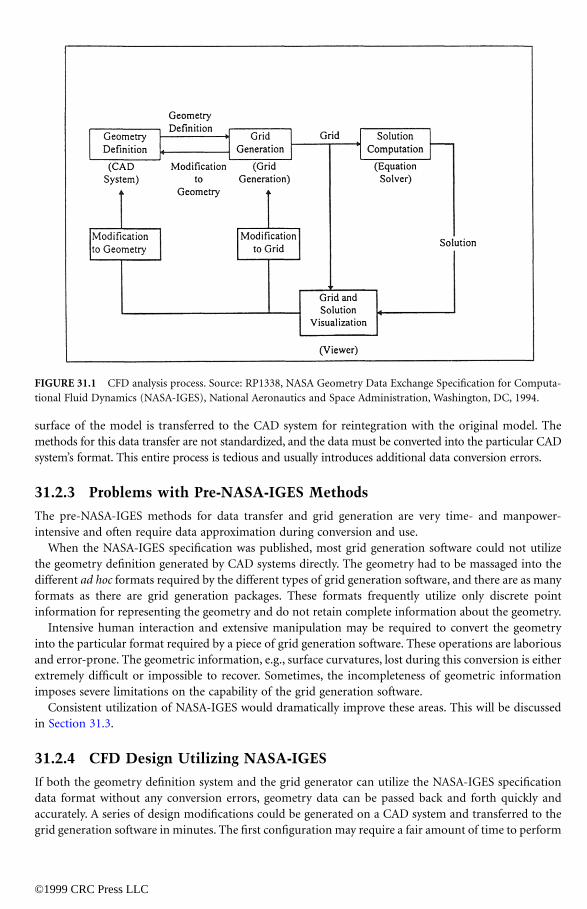
Research in CFD is accomplished by modeling the fluid as a discrete set of points and computing thevelocity and other properties of the fluid at each of these points. The set of points is referred to as a“grid” or “mesh.” A general representation of the CFD analysis process and the data transferred is shownin Figure 31.1.
Two forms of geometry definition are utilized by grid generation tools: surface definition and soliddefinition. In surface definition, the surfaces of the object to be analyzed are required by the gridgeneration tool. Currently, a majority of the grid generation tools require this surface geometry definition.Most of the grid generation tools utilizing surface definition are used interactively in the grid generationprocess.
Solid definition is usually required by tools that perform automatic grid generation. Currently, onlya few grid generation tools utilize solid geometry definition. The NASA-IGES specification is intendedfor surface geometry only; future enhancements may include solid definition.
31.2.2 The CFD Design Process
When CFD is used for design, the analysis process must be done a great many times in order to determinean optimal design. If a computer-aided design (CAD) system is available to the analysis group, thegeometry is modified on the CAD system, the new data are transferred to the grid generator, and thegrid generation process is repeated. This “pipeline” is repeated for each different design modification.Even though most current CAD systems can provide geometry in IGES format today, transferring newgeometry for each analysis has to be done via data conversion, since not all grid generation tools currentlyread IGES data. This conversion is tedious and usually introduces additional errors.
CAD systems are often not available to the analysis group. In these cases, the grid is modified and therest of the grid generation process is repeated. Current tools perform this geometry modification throughchanges to the grid representing the surface of the model. Such tools are limited in their capabilities andintroduce additional data errors. Once a particular configuration is selected, the grid representing the
©1999 CRC Press LLC
surface of the model is transferred to the CAD system for reintegration with the original model. Themethods for this data transfer are not standardized, and the data must be converted into the particular CADsystem’s format. This entire process is tedious and usually introduces additional data conversion errors.
31.2.3 Problems with Pre-NASA-IGES Methods
The pre-NASA-IGES methods for data transfer and grid generation are very time- and manpower-intensive and often require data approximation during conversion and use.
When the NASA-IGES specification was published, most grid generation software could not utilizethe geometry definition generated by CAD systems directly. The geometry had to be massaged into thedifferent ad hoc formats required by the different types of grid generation software, and there are as manyformats as there are grid generation packages. These formats frequently utilize only discrete pointinformation for representing the geometry and do not retain complete information about the geometry.
Intensive human interaction and extensive manipulation may be required to convert the geometryinto the particular format required by a piece of grid generation software. These operations are laboriousand error-prone. The geometric information, e.g., surface curvatures, lost during this conversion is eitherextremely difficult or impossible to recover. Sometimes, the incompleteness of geometric informationimposes severe limitations on the capability of the grid generation software.
Consistent utilization of NASA-IGES would dramatically improve these areas. This will be discussedin Section 31.3.
31.2.4 CFD Design Utilizing NASA-IGES
If both the geometry definition system and the grid generator can utilize the NASA-IGES specificationdata format without any conversion errors, geometry data can be passed back and forth quickly andaccurately. A series of design modifications could be generated on a CAD system and transferred to thegrid generation software in minutes. The first configuration may require a fair amount of time to perform
FIGURE 31.1 CFD analysis process. Source: RP1338, NASA Geometry Data Exchange Specification for Computa-tional Fluid Dynamics (NASA-IGES), National Aeronautics and Space Administration, Washington, DC, 1994.
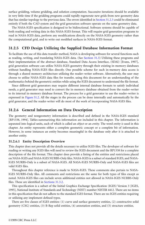
surface gridding, volume gridding, and solution computation. Successive iterations should be availablein very little time if the gridding programs could rapidly regenerate new grids from new geometry data
©1999 CRC Press LLC
that has similar topology to the previous data. The errors identified in Section 31.2.3 could be eliminatedentirely if both the CAD system and the grid generation software operate on the same geometry data.
The NASA-IGES specification is designed to be bidirectional. Software systems should be capable ofboth reading and writing data in this NASA-IGES format. This will require grid generation programs toread in NASA-IGES data, perform any modifications directly on the NASA-IGES geometry rather thanthe computational grid, and to write out modified surfaces in NASA-IGES format.
31.2.5 CFD Design Utilizing the Supplied Database Information Format
To facilitate the use of this data transfer method, NASA is developing software for several functions suchas reading, writing, and translating NASA-IGES data. (See Section 31.3) Utilizing these programs andtheir implementation of the abstract database, Standard Data Access Interface, (SDAI) [Evans, 1997],grid generation software can utilize NASA-IGES geometry through their existing in-memory databaseswithout handling NASA-IGES files directly. One possible scheme for such in-memory data access isthrough a shared memory architecture utilizing the reader–writer software. Alternatively, the user maychoose to utilize NASA-IGES data files for transfer, using this document for an understanding of themathematics behind the geometric entities while using the IGES document to understand the file format.
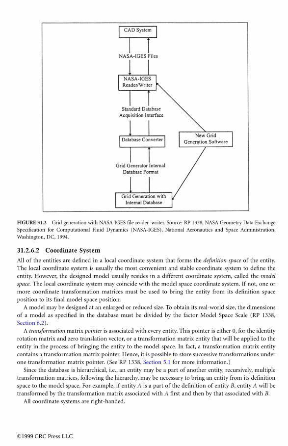
Since different grid generators may require different internal database formats to satisfy individualneeds, a grid generator may need to convert the in-memory database obtained from the reader–writerto its internal in-memory database format. The process for a grid generator to use the reader–writer isexpressed in Figure 31.2. All the stages in the process can be done internally and automatically by thegrid generator, and the reader-writer will do most of the work of incorporating NASA-IGES files.
31.2.6 General Information on Data Description
The geometry and nongeometry information is described and defined in the NASA-IGES standard[RP1338, 1994]. Tables summarizing this information are included in this chapter. The information isseparated into logical units, each of which is called an object or an entity. The word entity is used in thischapter. An entity represents either a complete geometric concept or a complete bit of information.However, in some instances an entity becomes meaningful in the database only after it is attached toanother entity.
31.2.6.1 Entity Description Overview
This chapter does not provide all the details necessary to utilize IGES files. The developer of software forreading or writing any IGES files will need to review the IGES document and the RP1338 for a completedescription of the file format. This chapter does provide a listing of the entities and restrictions placedon NASA-IGES and NASA-IGES NURBS-Only files. NASA-IGES is a subset of standard IGES, and NASA-IGES NURBS-Only is a subset of NASA-IGES. All NASA-IGES NURBS-Only and NASA-IGES files arevalid IGES files.
Throughout this chapter reference is made to NASA-IGES. These comments also pertain to NASA-IGES NURBS-Only files. All comments and restrictions are the same for both types of files except asnoted. NASA-IGES files can include seven additional entities not allowed in NASA-IGES NURBS-Onlyfiles. These are identified in Sections 31.3.2.
This specification is a subset of the Initial Graphics Exchange Specification (IGES) Version 3 [IGES,1995], National Institute of Standards and Technology (NIST) number NISTIR 4412. There are no itemsin this specification that do not adhere to the standard IGES format. There are no IGES entities requiringor utilizing any implement defined types.
There are five classes of IGES entities: (1) curve and surface geometry entities, (2) constructive solidgeometry (CSG) entities, (3) B-Rep solid entities, (4) annotation entities, and (5) structure entities.
©1999 CRC Press LLC
31.2.6.2 Coordinate System
All of the entities are defined in a local coordinate system that forms the definition space of the entity.The local coordinate system is usually the most convenient and stable coordinate system to define theentity. However, the designed model usually resides in a different coordinate system, called the modelspace. The local coordinate system may coincide with the model space coordinate system. If not, one ormore coordinate transformation matrices must be used to bring the entity from its definition spaceposition to its final model space position.
A model may be designed at an enlarged or reduced size. To obtain its real-world size, the dimensionsof a model as specified in the database must be divided by the factor Model Space Scale (RP 1338,Section 6.2).
A transformation matrix pointer is associated with every entity. This pointer is either 0, for the identityrotation matrix and zero translation vector, or a transformation matrix entity that will be applied to theentity in the process of bringing the entity to the model space. In fact, a transformation matrix entitycontains a transformation matrix pointer. Hence, it is possible to store successive transformations underone transformation matrix pointer. (See RP 1338, Section 5.1 for more information.)
Since the database is hierarchical, i.e., an entity may be a part of another entity, recursively, multipletransformation matrices, following the hierarchy, may be necessary to bring an entity from its definitionspace to the model space. For example, if entity A is a part of the definition of entity B, entity A will betransformed by the transformation matrix associated with A first and then by that associated with B.
All coordinate systems are right-handed.
FIGURE 31.2 Grid generation with NASA-IGES file reader–writer. Source: RP 1338, NASA Geometry Data ExchangeSpecification for Computational Fluid Dynamics (NASA-IGES), National Aeronautics and Space Administration,Washington, DC, 1994.
31.2.6.3 Common Information
Information common to all entities is not described for each individual entity. This information includes,
©1999 CRC Press LLC
but is not limited to, color, level, form, and transformation matrix pointer.Some information common to the entire model and data files is also contained in the database. This
includes, but is not limited to, text identifying the model, measuring system units, and data of file creation.This information corresponds to the global section of the IGES files. The common and global informationand other database related issues are discussed in Section 6 of the NASA-IGES standard (RP1338, 1994).
31.3 Best Practices
This section is divided into four subsections. The first, Multidisciplinary Data Exchange Standards, relatesfollow-on activities that have occurred since the NASA-IGES standard was published. The second,Summary of Entity Types and Recommended Usage, describes the contents of the standard and how touse its elements. In the third section, three case studies are presented. The last section, Other NASA-IGES compatible software, lists some additional NASA-IGES-compatible software not mentioned in thecase studies.
31.3.1 Multidisciplinary Data Exchange Standards
The charter of the NASA Geometry Exchange Standard Subcommittee was to develop a standard thatwas focused on CFD. It was intended that the standard work that was done would be expanded to coverother disciplines. The section gives information on that effort.
Turbomachinery characteristics are strongly influenced by a combination of aerodynamic, thermal,and structural effects. The predictions of turbomachinery performance for off-design conditions usuallyrequire the inclusion of the thermal and structural displacements to determine blade operating shape.Also, blade, rotor, and casing deflections and tip clearance changes have significant effects on aerodynamicstability and impact to the overall operability of turbomachinery.
The ability to address these multidisciplinary aerodynamic, thermal, and structural effects related toturbomachinery does not require a tightly coupled and fully integrated aeroelastic analysis. The analysisof steady state operating points can be achieved by exchanging boundary condition data between multipledisciplines required for turbomachinery analysis. Stand alone computational fluid dynamics (CFD) andthermal/structural finite element analysis (FEA) codes can be loosely coupled in this manner to obtainturbomachinery analysis results for the steady state coupled effects in a small number of loosely couplediterations.
An enhanced method for exchanging this boundary condition data between aerodynamics CFD gridsand thermal/structural FEA analysis grids has been developed by NASA, DOD Navy, and Boeing. Thisenhanced method associates the boundary condition data from each analysis discipline’s grid with thegeometric representation. This method also moves toward a standardized method for the exchange ofloosely coupled engineering analysis information. This methodology relies heavily on the use of nonuni-form rational B-spline (NURBS) as the technique to represent both the geometry and the boundaryconditions information. NURBS mathematics (see Chapter 30) has become the de facto standard in theCAD/CAM industry for definition of geometric information (see Chapter 31). Therefore, the multidis-ciplinary method focuses on associating the engineering data in the NURBS mathematical form. Themethod also relies on the NASA-IGES subset with the inclusion of IGES user defined-extensions (IGES5000 entities) for the exchange of both the geometric and boundary data definitions.
The NASA-IGES subset was initially established and adopted by the NASA Centers for the exchangeof geometric definitions between CAD/CAM systems and aerodynamic CFD analysis. NASA Lewis andDOD Navy are exploring prototype methods to extend the NASA-IGES geometric subset to multidisci-plinary analysis for turbomachinery and for future ISO STEP engineering analysis standardization. The
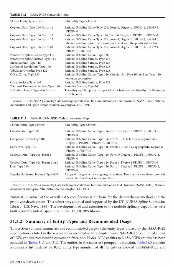
TABLE 31.1
NASA-IGES Conversion Map
>From Entity Type (,Form) >To Entity Type (,Form)
©1999 CRC Press LLC
NASA-IGES subset of the overall IGES specification is the basis for the data exchange method and theprototype development. This subset was adopted and supported by the DT_NURBS Spline SubroutineLibrary [U.S. Navy, 1993]. The development of and extension to the multidisciplinary capabilities werebuilt upon the initial capabilities in the DT_NURBS library.
31.3.2 Summary of Entity Types and Recommended Usage
This section contains summaries and recommended usage of the entity types utilized by the NASA-IGESspecification as listed in the several tables included in this chapter. Since NASA-IGES is a limited subsetof IGES entities, recommend conversion from non-NASA-IGES entities to NASA-IGES entities has beenincluded in Tables 31.1 and 31.2. The entities in the tables are grouped by function. Table 31.3 containsa summary list, ordered by IGES entity type number, of all the entities allowed in NASA-IGES and
Copious Data, Type 106, Form 11 Rational B-Spline Curve Type 126, Form 0, Degree 1, PROP1 1, PROP3 1, PROP4 0
Copious Data, Type 106, Form 12 Rational B-Spline Curve Type 126, Form 0, Degree 1, PROP3 1, PROP4 0Copious Data, Type 106, Form 13 Rational B-Spline Curve Type 126, Form 0, Degree 1, PROP3 1, PROP4 0,
the information about the vectors associated with the points will be lostCopious Data, Type 106, Form 63 Rational B-Spline Curve Type 126, Form 0, Degree 1, PROP1 1, PROP2 1,
PROP3 1, PROP4 0Parametric Spline Curve, Type 112 Rational B-Spline Curve, Type 126Parametric Spline Surface, Type 114 Rational B-Spline Surface, Type 128Ruled Surface, Type 118 Rational B-Spline Surface, Type 128Surface of Revolution, Type 120 Rational B-Spline Surface, Type 128Tabulated Cylinder, Type 122 Rational B-Spline Surface, Type 128Offset Curve, Type 130 Rational B-Spline Curve, Type 126, Circular Arc Type 100 or Line Type 110
on exact conversion.Offset Surface, Type 140 Rational B-Spline Surface, Type 128Trimmed Parametric Surface, Type 144 Bounded Surface, Type 143Definition Levels, Type 406, Form 1 The entity with this property is placed in the first level identified by this Definition
Levels entity
Source: RP1338, NASA Geometry Data Exchange Specification for Computational Fluid Dynamics (NASA-IGES), NationalAeronautics and Space Administration, Washington, DC, 1994.
TABLE 31.2 NASA-IGES-NURBS-Only Conversion Map
>From Entity Type (,Form) >To Entity Type (,Form)
Circular Arc, Type 100 Rational B-Spline Curve, Type 126, Form 2, Degree 1,PROP1 1, PROP3 0, PROP4 0
Composite Curve, Type 102 Rational B-Spline Curve, Type 126, Forms 1, 2, 3, 4, or 5 as appropriate, Degree 1, PROP1 1, PROP3 1, PROP4 0
Conic Arc, Type 104 Rational B-Spline Curve, Type 126, Forms 3, 4, or 5 as appropriate, Degree 1, PROP1 1, PROP4 0
Copious Data, Type 106, Form 1 Rational B-Spline Curve, Type 126, Form 0, Degree 1, PROP1 1, PROP3 1,PROP4 0
Copious Data, Type 106, Forms 2 or 3 Rational B-Spline Curve, Type 126, Form 0, Degree 1 PROP3 1, PROP4 0Line, Type 110 Rational B-Spline Curve, Type 126, Form 1, Degree 1, PROP1 1, PROP3 1,
PROP4 0Singular Subfigure, Instance Type 408 A copy of the geometry using original entities. These entities are then converted
as specified in these Conversion Maps
Source: RP1338, NASA Geometry Data Exchange Specification for Computational Fluid Dynamics (NASA-IGES), NationalAeronautics and Space Administration, Washington, DC, 1994.
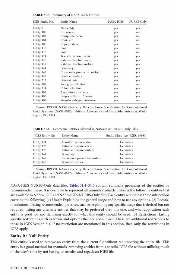
TABLE 31.3
Summary of NASA-IGES Entities
IGES Entity No. Entity Name NASA-IGES NURBS-Only
©1999 CRC Press LLC
NASA-IGES NURBS-Only data files. Tables 31.4–31.6 contain summary groupings of the entities byrecommended usage. It is desirable to represent all geometric objects utilizing the following entities thatare available in NASA-IGES and NASA-IGES NURBS-Only files. Each entity section has three subsectionscovering the following: (1) Usage: Explaining the general usage and how to use any options. (2) Recom-mendations: Listing recommended practices, such as explaining any specific usage that is desired but notrequired, listing any alternate entities that may be preferred over this one, and what application eachentity is good for and itemizing exactly for what this entity should be used. (3) Restrictions: Listingspecific restrictions such as forms and options that are not allowed. These are additional restrictions tothose in IGES Version 5.1. If no restriction are mentioned in this section, then only the restrictions inIGES apply.
Entity 0 : Null Entity
This entity is used to remove an entity from the current file without renumbering the entire file. Thisentity is a good method for manually removing entities from a specific IGES file without utilizing muchof the user’s time by not having to reorder and repack an IGES file.
Entity 0 Null entity yes yesEntity 100 Circular arc yes noEntity 102 Composite curve yes noEntity 104 Conic arc yes noEntity 106 Copious data yes noEntity 110 Line yes noEntity 116 Point yes noEntity 124 Transformation matrix yes yesEntity 126 Rational B-spline curve yes yesEntity 128 Rational B-spline surface yes yesEntity 141 Boundary yes yesEntity 142 Curve on a parametric surface yes yesEntity 143 Bounded surface yes yesEntity 212 General note yes yesEntity 308 Subfigure definition yes noEntity 314 Color definition yes yesEntity 402 Associativity instance yes yesEntity 406 Property, Form 15: name yes yesEntity 408 Singular subfigure instance yes no
Source: RP1338, NASA Geometry Data Exchange Specification for ComputationalFluid Dynamics (NASA-IGES), National Aeronautics and Space Administration, Wash-ington, DC, 1994.
TABLE 31.4 Geometric Entities Allowed in NASA-IGES NURB-Only Files
IGES Entity No. Entity Name Entity Class (see [IGES, 1995])
Entity 124 Transformation matrix GeometryEntity 126 Rational B-spline curve GeometryEntity 128 Rational B-spline surface GeometryEntity 141 Boundary GeometryEntity 142 Curve on a parametric surface GeometryEntity 143 Bounded surface Geometry
Source: RP1338, NASA Geometry Data Exchange Specification for ComputationalFluid Dynamics (NASA-IGES), National Aeronautics and Space Administration, Wash-ington, DC, 1994.
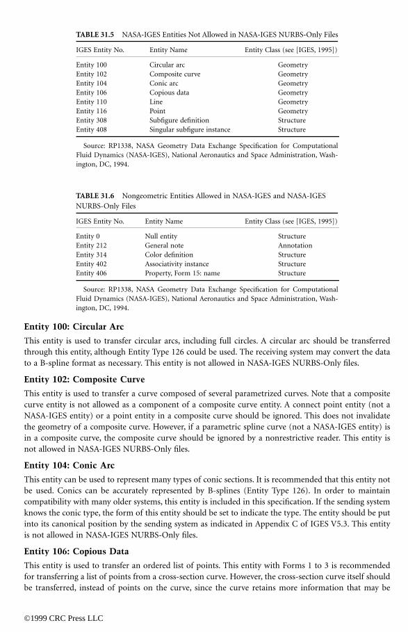
TABLE 31.5
NASA-IGES Entities Not Allowed in NASA-IGES NURBS-Only Files
IGES Entity No. Entity Name Entity Class (see [IGES, 1995])
©1999 CRC Press LLC
Entity 100: Circular Arc
This entity is used to transfer circular arcs, including full circles. A circular arc should be transferredthrough this entity, although Entity Type 126 could be used. The receiving system may convert the datato a B-spline format as necessary. This entity is not allowed in NASA-IGES NURBS-Only files.
Entity 102: Composite Curve
This entity is used to transfer a curve composed of several parametrized curves. Note that a compositecurve entity is not allowed as a component of a composite curve entity. A connect point entity (not aNASA-IGES entity) or a point entity in a composite curve should be ignored. This does not invalidatethe geometry of a composite curve. However, if a parametric spline curve (not a NASA-IGES entity) isin a composite curve, the composite curve should be ignored by a nonrestrictive reader. This entity isnot allowed in NASA-IGES NURBS-Only files.
Entity 104: Conic Arc
This entity can be used to represent many types of conic sections. It is recommended that this entity notbe used. Conics can be accurately represented by B-splines (Entity Type 126). In order to maintaincompatibility with many older systems, this entity is included in this specification. If the sending systemknows the conic type, the form of this entity should be set to indicate the type. The entity should be putinto its canonical position by the sending system as indicated in Appendix C of IGES V5.3. This entityis not allowed in NASA-IGES NURBS-Only files.
Entity 106: Copious Data
This entity is used to transfer an ordered list of points. This entity with Forms 1 to 3 is recommendedfor transferring a list of points from a cross-section curve. However, the cross-section curve itself shouldbe transferred, instead of points on the curve, since the curve retains more information that may be
Entity 100 Circular arc GeometryEntity 102 Composite curve GeometryEntity 104 Conic arc GeometryEntity 106 Copious data GeometryEntity 110 Line GeometryEntity 116 Point GeometryEntity 308 Subfigure definition StructureEntity 408 Singular subfigure instance Structure
Source: RP1338, NASA Geometry Data Exchange Specification for ComputationalFluid Dynamics (NASA-IGES), National Aeronautics and Space Administration, Wash-ington, DC, 1994.
TABLE 31.6 Nongeometric Entities Allowed in NASA-IGES and NASA-IGES NURBS-Only Files
IGES Entity No. Entity Name Entity Class (see [IGES, 1995])
Entity 0 Null entity StructureEntity 212 General note AnnotationEntity 314 Color definition StructureEntity 402 Associativity instance StructureEntity 406 Property, Form 15: name Structure
Source: RP1338, NASA Geometry Data Exchange Specification for ComputationalFluid Dynamics (NASA-IGES), National Aeronautics and Space Administration, Wash-ington, DC, 1994.
useful in the receiving system. In addition to the point coordinate data, a vector is associated with everypoint in the parameter data section of this entity with Form 3. It is recommended that, if Form 3 is used,
©1999 CRC Press LLC
this vector be set as the direction vector of the cross-section curve. For other recommended usages ofthis entity, see Entity 402. Only Forms 1 to 3 are included in this specification. This entity is not allowedin NASA-IGES NURBS-Only files.
Entity 110: Line
The line entity is used to transfer line segments. It is preferred to transfer line segments by this entityrather than by Entity Type 126, since this is a commonly used and more compact representation. Thisentity is not allowed in NASA-IGES NURBS-Only files.
Entity 116: Point
This entity is used to transfer a point in space. The list of points on a curve or the mesh of points on asurface should be transferred through the appropriate entities, see Entity Type 106 and Entity Type 402.The pointer (PD Index 4) in the parameter data section, which points to the subfigure definition entityspecifying the display symbol, will be ignored. The display symbol will be determined by the receivingsystem. This entity is not allowed in NASA-IGES NURBS-Only files.
Entity 124: Transformation Matrix
The transformation matrix is used to transform an entity from its local coordinate system to its truemodel space position. A number of entities are required by IGES to be transferred in their canonicaldefinition space. For these entities, a transformation matrix is required to relocate them to their trueposition. Only Form 0 and Form 1 are included in this chapter. The other forms, for view transformationand finite element modeling, are not included.
Entity 126: Rational B-Spline Curve
This format is used as the primary entity for curve transfer. All the other curve types, excluding lines(Entity Type 110), conics (Entity Type 104), and circular arcs (Entity Type 100), must be converted(maybe with approximation) to this entity for transfer. This is the most flexible format to represent curvesand is recommended for transferring all curves. All lines, circular arcs, and conics can be represented bythis entity. This entity contains forms that identify each curve type. If the sending system knows the formof the curve, the form of this entity should be set appropriately. All parametric splines can also berepresented by this entity. Software for the required conversion to this entity can be obtained from NationalInstitute of Standards and Technology (NIST), U.S. Department of Commerce, Gaithersburg, MD.
Entity 128: Rational B-Spline Surface
This entity is used as the primary entity for surface transfer. All the other surface types must be converted(maybe with approximation) to this entity for transfer. This is the most flexible format to representsurfaces and is recommended for transferring all surfaces. This entity has forms for some analytic surfaces.If the sending system can determine the Form of the surface, the Form of this entity should be setappropriately.
Entity 141: Boundary
This entity should be used with Entity Type 143. It describes one boundary of a bounded surface. Thereare two types in this entity. Type 0 transfers only model space curves, and the surface may not beparametric. Type 1 transfers both parameter and model space curves, and the surface has to be parametric.Only Type 1 is used in the NASA-IGES specification.
Entity 142: Curve on a Parametric Surface
This entity is used to transfer a curve on a parametric surface when its parameter space curve is important.A curve on a parametric surface may be a curve from the projection of another curve onto the surface,a curve from the intersection of two surfaces, or an isoparametric curve. IGES provides the curve on
parametric surface entity for use in either of two ways. It can be used with the trimmed surface entity(Type 144) to form a trimmed surface. Entity 144 is not allowed under this specification, so this use is
©1999 CRC Press LLC
not allowed. The boundary entity (Type 141) should be used for this purpose. The other use for thisentity is to simply represent a curve on a surface. This is the only use allowed for this entity under thisspecification.
Entity 143: Bounded Surface
The bounded surface entity is used to transfer a bounded surface, a surface whose domain space isrelimited (trimmed back) from its original domain. It should be used with Entity Type 141, boundaryentity. This entity should be used instead of Entity Type 144, the trimmed parametric surface, for asurface with relimited domain, since Entity Type 144 disallows surfaces with poles or seams, which limitsits usage. There are two types in this entity. Type 0 transfers only model space curves, and the surfacemay not be parametric. Type 1 transfers both parameter and model space curves, and the surface has tobe parametric. Only Type 1 is used.
Entity 212: General Note
This entity is used to pass textual information about the geometry. This can include such informationas the history of the object, relevant airfoil section numbers, and reference documents. A general noteentity can exist separately or can be associated with another entity or entities. This entity is recommendedas the entity for transferring relevant nongeometric design information. Form 0, which states that thetext strings in the note are not related to each other positionally, is the only form included in thisspecification. This is also the default form. Font 1, the default font style for the ASCII character set, isthe only font included in this specification. This allows the receiving system to use its default font fordisplay.
Entity 308: Subfigure Definition
The subfigure definition and subfigure instance entities allow one copy of the geometry to be placed inmany locations in a design without duplicating the geometry. For example, in a turbine engine design,all the turbine blades on the same stage are identical in shape. Only the geometry for one generic blademust be defined by using a subfigure definition entity. All the blades can then be created with the subfigureinstance entity. The user should be discriminatory and exercise sound judgment in using this entity. Forexample, it is a good practice to represent turbine blades with instances, since this reduces file sizestremendously and makes processing of the files much easier. However, to represent the two wings of anaircraft with an instance may not be wise, since the geometry for the wings is not stored explicitly in aninstance; if the user decides to build a CFD grid on the wings, the grid generation software must createthe geometry first. The grid generation software will probably not have the capability to create thegeometry for an instance. This entity is not allowed in NASA-IGES NURBS-Only files.
Entity 314: Color Definition
Entity 314 is used to define additional colors (there are nine predefined colors in IGES). There are norecommendations on this entity, as its usage is self-evident.
Entity 402: Associativity Instance
This entity is used to group geometry entities into classes. It contains pointers to the grouped entities,called the members of the class. There are 18 predefined forms (classes), of which four (Forms 1, 7, 14,15) are for grouping. Forms 1 and 7 are for unordered groups, i.e., the entities pointed to by this entityare an unordered set. Forms 14 and 15 are for ordered groups, i.e., there is an order specified for theentities pointed to by this entity; the order is defined by the sequence of the pointers specified withinthis entity. Unordered groups are frequently used to group surfaces from the same object, hence creatingone group per object. Currently, very few CAD systems utilize the ordered group forms. Ordered groupsare recommended for grouping a sequence of cross sections and associating them as a surface. In the
recommended usage of the ordered forms, it is not required that the curves be from one surface; thisinformation is irrelevant to this entity. The curves could be sliced from numerous surfaces. In this usage,
©1999 CRC Press LLC
the members of the class will be the cross-section curves. Ordered groups are also recommended to definea mesh of points (either topologically rectangular or nonrectangular) from a surface. In this usage, themembers of the class will be the copious data entity (Entity Type 106, Forms 1–3). The same format isrecommended to transfer points on a surface sampled along a list of cross-section curves on the surface.Only Forms 1, 7, 14, and 15 are included in this specification.
Entity 406: Property, Form15: Name
This entity is used to associate a name (or brief description) to an entity or a group of entities. All itcontains is a text string that is the name. This entity would be appropriate for grouping a portion of theobject together, such as a wing, and assigning it a name “wing.” Longer comments should be handledthrough the general note entity.
Entity 408: Singular Subfigure Instance
The singular subfigure instance entity creates one instance of a subfigure, which is defined by a subfiguredefinition entity. See Section 3.4.15 of RP1338 for more information. See Entity 308 for recommendedusage. This entity is not allowed in NASA-IGES NURBS-Only files.
31.3.3 Case Studies:
31.3.3.1 Blade Surface Geometry Modeling
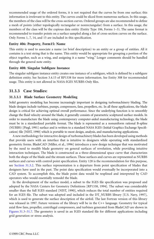
Solid geometry modeling has become increasingly important in designing turbomachinery blading. Theblade designs include turbines, pumps, compressors, fans, propellers, etc. In all these applications, the bladedesign is critical for achieving optimal overall performance. Since the underlying function is to smoothlychange the fluid velocity around the blade, it generally consists of pararnetric sculptured surface models. Inorder to manufacture the blade using contemporary computer-aided manufacturing technology, the blademust be in a standardized portable format. The blade is represented as a nonuniform rational B-spline(NURBS) [Piegl, 1991] surface and is written to a standard NASA IGES (Initial Graphics Exchange Specifi-cation) file [NIST, 1990] which is portable to most design, analysis, and manufacturing applications.
A new methodology for interactive design of turbomachinery blades has been developed using methodsthat provide users with an interface that is intuitive to designers while operating with standardizedgeometric forms. BladeCAD [Miller, et al., 1996] introduces a new design technique that was motivatedby the need to modify blade geometry on general surfaces of revolution, while providing intuitiveinteraction techniques. The blade is constructed as a three-dimensional space curve that characterizesboth the shape of the blade and the stream surfaces. These surfaces and curves are represented as NURBSsurfaces and curves with control point specification. Entity 128 is the recommendation for this purpose,see Section 31.3.2. This surface representation is a departure from point specification of blades thatdesigners have used in the past. The point data specification would eventually be incorporated into aCAD system. To accomplish this, the blade point data would be resplined and interpreted by CADoperators who would essentially remodel the blade.
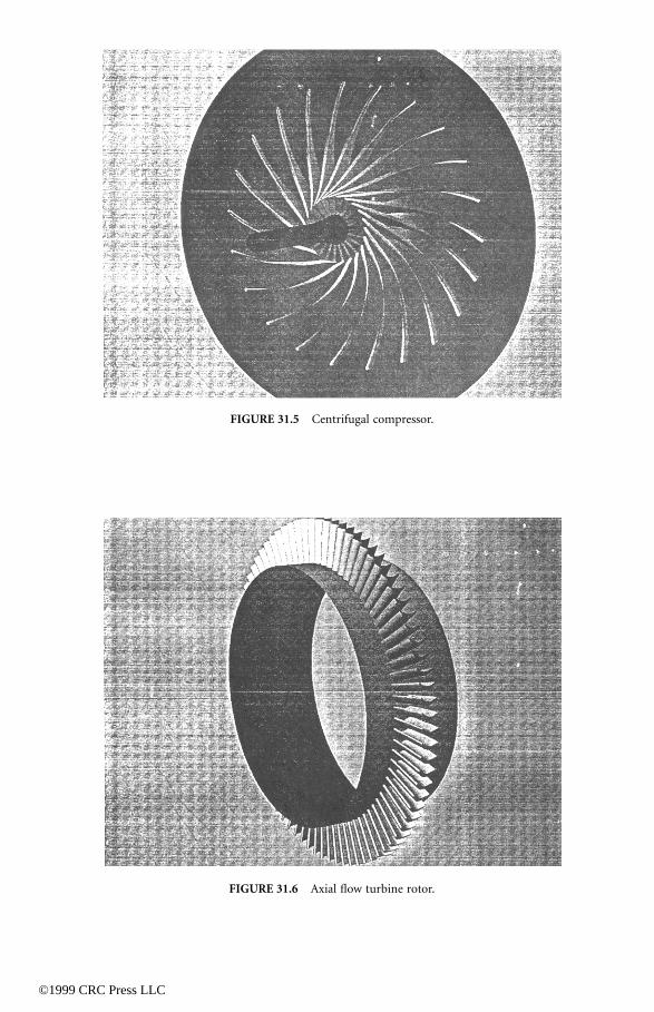
In the development of the surface model, a subset to the IGES file specification was proposed andadopted by the NASA Centers for Geometry Definitions [RP1338, 1994]. The subset was considerablysmaller than the full IGES standard [NIST, 1990], which reduces the total number of entities requiredfor an IGES file. The subset was adopted and included in the DT_NURBS library [U.S. Navy, 1997],which is used to generate the surface description of the airfoil. The last Fortran version of this librarywas released in 1997. Future versions of the library will be in the C++ language. Geometry for typicalaxial flow fans, propeller, centrifugal compressors, and turbines generated from BladeCAD are shown inFigures 31.3–31.7. The geometry is saved in an IGES standard file for different applications includinggrid generation or stress analysis.
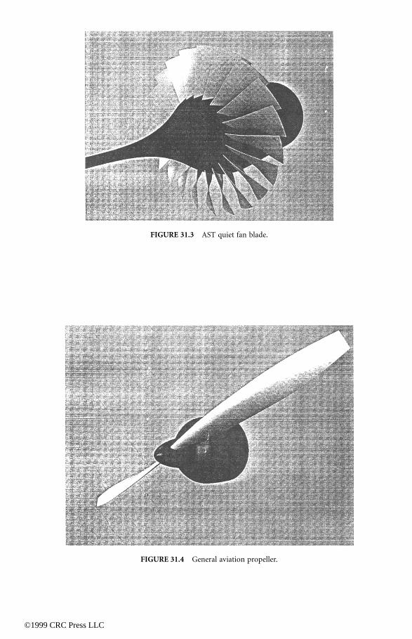
FIGURE 31.3 AST quiet fan blade.
FIGURE 31.4 General aviation propeller.
©1999 CRC Press LLC
©1999 CRC Press LLC
FIGURE 31.5 Centrifugal compressor.
FIGURE 31.6 Axial flow turbine rotor.
©1999 CRC Press LLC
31.3.3.2 Computational Fluid Dynamics
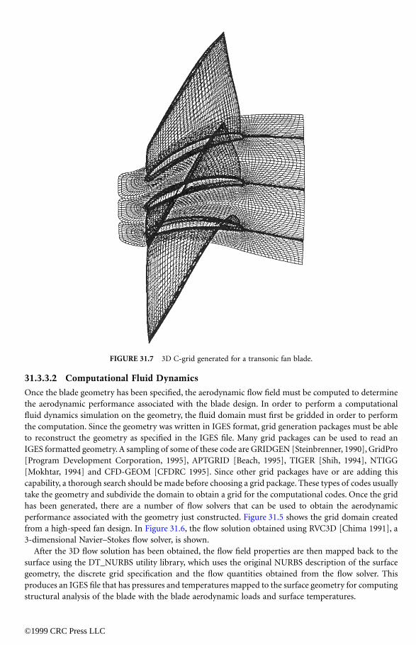
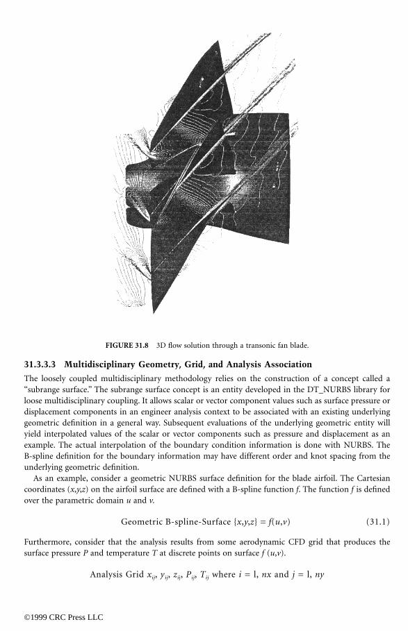
Once the blade geometry has been specified, the aerodynamic flow field must be computed to determinethe aerodynamic performance associated with the blade design. In order to perform a computationalfluid dynamics simulation on the geometry, the fluid domain must first be gridded in order to performthe computation. Since the geometry was written in IGES format, grid generation packages must be ableto reconstruct the geometry as specified in the IGES file. Many grid packages can be used to read anIGES formatted geometry. A sampling of some of these code are GRIDGEN [Steinbrenner, 1990], GridPro[Program Development Corporation, 1995], APTGRID [Beach, 1995], TIGER [Shih, 1994], NTIGG[Mokhtar, 1994] and CFD-GEOM [CFDRC 1995]. Since other grid packages have or are adding thiscapability, a thorough search should be made before choosing a grid package. These types of codes usuallytake the geometry and subdivide the domain to obtain a grid for the computational codes. Once the gridhas been generated, there are a number of flow solvers that can be used to obtain the aerodynamicperformance associated with the geometry just constructed. Figure 31.5 shows the grid domain createdfrom a high-speed fan design. In Figure 31.6, the flow solution obtained using RVC3D [Chima 1991], a3-dimensional Navier–Stokes flow solver, is shown.
After the 3D flow solution has been obtained, the flow field properties are then mapped back to thesurface using the DT_NURBS utility library, which uses the original NURBS description of the surfacegeometry, the discrete grid specification and the flow quantities obtained from the flow solver. Thisproduces an IGES file that has pressures and temperatures mapped to the surface geometry for computingstructural analysis of the blade with the blade aerodynamic loads and surface temperatures.
FIGURE 31.7 3D C-grid generated for a transonic fan blade.
©1999 CRC Press LLC
31.3.3.3 Multidisciplinary Geometry, Grid, and Analysis Association
The loosely coupled multidisciplinary methodology relies on the construction of a concept called a“subrange surface.” The subrange surface concept is an entity developed in the DT_NURBS library forloose multidisciplinary coupling. It allows scalar or vector component values such as surface pressure ordisplacement components in an engineer analysis context to be associated with an existing underlyinggeometric definition in a general way. Subsequent evaluations of the underlying geometric entity willyield interpolated values of the scalar or vector components such as pressure and displacement as anexample. The actual interpolation of the boundary condition information is done with NURBS. TheB-spline definition for the boundary information may have different order and knot spacing from theunderlying geometric definition.
As an example, consider a geometric NURBS surface definition for the blade airfoil. The Cartesiancoordinates (x,y,z) on the airfoil surface are defined with a B-spline function f. The function f is definedover the parametric domain u and v.
Geometric B-spline-Surface {x,y,z} = f(u,v) (31.1)
Furthermore, consider that the analysis results from some aerodynamic CFD grid that produces thesurface pressure P and temperature T at discrete points on surface f (u,v).
Analysis Grid xij, yij, zij, Pij, Tij where i = l, nx and j = l, ny
FIGURE 31.8 3D flow solution through a transonic fan blade.
The corresponding surface parameters
u
ij
and
v
ij
are either known from the original aerodynamic CFDgrid discretization or can be calculated. A second B-spline function
g
with parameters
s
and
t
can be
©1999 CRC Press LLC
constructed from the value of u, v, P, T so that:
Boundary Condition B-spline Function {u,v,P,T} = g(s,t) (31.2)
Subsequently the function g in Eq. 31.2 can be evaluated using the parameters s and t. The evaluationof the boundary condition B-spline function g produces values of u, v, P, T. The parametric values u andv obtained from the evaluation of the function g can then be used to evaluate the function f in Eq. 31.1to produce geometric values of x, y, z. The evaluation of the f and g functions can be composed togetherto produce the following:
x, y, z, P, T = f{g{s, t}} (31.3)
Therefore, the evaluation of the composition of functions using parametric values s and t in Eq. 31.3would produce x, y, z, P, T. In this example, the geometric and boundary condition data needed for astructural FEA (finite element analysis) grid is generated. The DT_NURBS library has been developedby NASA, DOD Navy, and Boeing to provide this encapsulated functionality for the subrange methodsand association of each analysis discipline’s geometry, grid, and analysis (GGA) data.
To demonstrate this fundamental discipline couple methodology and technique, NASA Lewis hasdeveloped several prototype multidisciplinary coupling tools. The prototype software was used to dem-onstrate methodology for steady state aeroelastic analysis problems for turbomachinery blading. NASAhas developed mapping and interpolation prototypes for pre and post processors aerodynamic CFDanalysis APTGRID [Beach 1995] and FEA structural analysis SABER [Thorp, 1995] based on theDT_NURBS library’s GGA concept. For this prototype development and the testing of these methodsthe mapping and interpolation software was incorporated directly into both the CFD and FEA gridgenerators. This proved to be the most convenient approach, but is not a necessity.
The process was applied to the prediction of the hot running blade shape of the NASA TransonicRotor 37 stage. The Rotor 37 rotor stage was used because experimental and analytical CFD and FEAdata was plentiful for this turbomachinery test case. Experimental data also included measure tip locationand displacement at operating speed from NASA Lewis rig testing. Both the pre- and postprocessingtools APTGRID and SABER along with the VSTAGE CFD and NASTRAN FEA analysis codes were usedto solve the steady-state aeroelastic problem. In this specific application, two aero/structural iterationswere sufficient to achieve a converged solution based on both pressure and displacement criteria to withinacceptable accuracy.
The loosely coupled geometry, grid and analysis method has proven to be an accurate and practicalapproach for loosely coupling aerodynamic CFD to thermal/structural FEA. Further, work is ongoing toenhance and expand this method to larger dimensional problems in terms of geometric complexity anddata exchange proportions. Plans are to incorporate this loosely coupled methodology into the ISO 10303Standard for the Exchange of Product Data (STEP), Part 42, for engineering analysis data exchange.
31.3.4 Other NASA-IGES Compatible Software
Although much NASA-IGES compatible software has been referenced in the above section, some wasnot covered. This section will deal with three additional codes. This is not meant to be a comprehensivelist. The reader is encouraged to search other sources for additional codes. Searching the Web is a goodstarting point.
It should be noted that while the codes included here are generally free of charge, many have restrictionson their release. The reader will need to check with the point of contact to determine the pertinentrestrictions. Since these are free codes, the reader should be cautioned that their quality will vary widely.
The following list of NASA-IGES compatible software contains the name of the code followed by abrief description and a point of contact (POC) for additional information.
• NASA-IGES Translator (NigesT) — POC: Jin Chou (415) 424-1202. NigesT is a noninteractiveprogram that reads NASA-IGES CAD data files, which is a subset of the IGES standard, and
©1999 CRC Press LLC
converts those entities it understands into NURBS. The resulting file is a NASA-IGES NURBS-Only file (NINO). (This is highly recommended by the author. Since most CAD systems outputextraneous IGES information that is of no use to a grid generator, NigesT can be used to filterout this information. If you are having trouble generating a grid from a IGES file generated by aNASA-IGES compatible CAD system and the grid generator is NASA-IGES compatible, run thefile through the NigesT software.)
• Portable Extensible Viewer (PEV) — POC: [email protected]. PEV is a programdesigned to read, write, evaluate, display, graphically manipulate, and analyze NURBS data. TheNURBS data may be stored in several predefined file formats (including NASA-IGES) or in a fileformat that can be read in by a user-defined function. The data may be multidisciplinary, includingnot only geometry information, but pressure and temperature defined over multiple time steps,and various conditions.
• Standard Data Access Interface (SDAI) for STEP Repositories — POCs: Jeff Meister (216) 433-6731.Austin L. Evans (216) 433-8313. The C++ SDAI implements classes and methods specified in thestandard data access interface for the C++ programming language, ISO/CD 10303-23. The SDAIis a function level interface that provides a standard model and syntax for creating and accessingSTEP-based entities contained within a database. Thus, the SDAI enables developers to buildapplications free of storage method specific function calls.
31.4 Research Issues and Summary
There are many open issues in the area of geometry and data exchange standards due to the fact thatnot all the standards have been defined nor fully implemented. This is especially true as one moves awayfrom simple surface representation and toward solid models and subrange surface data representation.The state of the art in the solid modeling area is currently at the same level surface modeling was at in1991 when our team began working on NASA-IGES. There is great difficulty in sharing solid modelsbetween various CAD systems. What is a solid model in one system is not read as a solid model whentransferred to another system. The use of subrange surfaces to map and exchange data between disciplinecodes is not yet an accepted practice.
It is currently planned that these issues will be addressed by the STEP standard. The PDES Inc., abusiness/government consortium, is currently coordinating the U.S. input to the STEP standards. ANASA PDES Working Group has been formed to work with PDES. This group is forging ahead with thework started by the team that wrote the NASA-IGES standard. One of the projects this group is workingon is to push for the incorporation of the GGA, subrange, data exchange method into ISO 10303 Part 42.Once this has been accomplished and a consistent solid modeling standard has been implemented, thegoal of being able to widely use a common, or master, model across heterogeneous hardware and softwaresystems will be achieved.
Further Information
A good introduction to curves, surfaces and NURBS representation of geometry and data can be found in the following reading list. The first two books are highly recommended.
Farin, G., Curves and Surfaces for Computer Aided Geometric Design, A Practical Guide, Third Edition.Academic Press, 1993.
Piegl, L. and Tiller, W., The NURBS Book, Monographs in Visual Communications. Springer, 1995.Bartels, R.H., Beatty, J.C., Barsky, B.A., An Introduction to Splines for Use in Computer Graphics and
Geometric Modeling, Morgan–Kaufmann, Palo Alto, CA, 1987.

Boehm, W., Farin, G., Kahmann, J., A Survey of Curve and Surface Methods in CAGD, Computer AidedGeometry Design. July 1984, Vol. 1, No. 1, pp. 1–60.
©1999 CRC Press LLC
de Boor, C., A Practical Guide to Splines. Springer Verlag, New York, 1978.Lee, E.T.Y., Rational quadratic Bézier representation for conics, Geometric Modeling: Algorithms and New
Trends. Farin, G., (Ed.), SIAM Philadelphia, 1987, pp. 3–19.Tiller, W. Rational B-splines for curve and surface representation, CG&A. Sept. 1983, Vol. 3, No. 10, pp.
61–69.Piegland, L. and Tiller, W., curve and surface constructions using rational B-splines, Computer-Aided
Design, Nov. 1987, Vol. 19, No. 9, pp. 485–498.Piegland, L. and Tiller, W., A menagerie of rational B-spline circles, IEEE Computer Graphics and Appli-
cations. Sept. 1989, Vol. 9, No. 5, pp. 48–56.
References
American National Standard Institute. Dimensioning and tolerancing, (Y14.5M-1982), 1982.Beach, T. APTGRID, User’s Guide and Reference Manual, 1995. Chima, R.V., Viscous three-dimensional calculations of transonic fan performance, NASA TM103800.
Presented at the 77th Symposium of the Propulsion and Energetics Panel CFD Techniques forPropulsion Applications, San Antonio, TX, May 1991.
CFDRC. CFD-GEOM, CFD Research Corporation, 1995.Evans, A.L., et al. NPSS Software Catalog, Version 1.0, NASA Lewis Research, Cleveland, Ohio, 1997.Farin, G. Curves and Surfaces for Computer Aided Geometric Design. Academic Press, 1988.Initial Graphics Exchange Specification (IGES), Version 5.3, distributed by National Computer Graphics
Association, Administrator, IGES/PDES Organization, 2722 Merrilee Drive, Suite 200, Fairfax, VA,1995.
Miller, P.L., Oliver, J.H., Miller, D.P., and Tweedt, D.L. BladeCAD: An interactive geometric design toolfor turbomachinery blades, NASA Technical Memorandum 107262, presented at the 41st GasTurbine and Aeroengine Congress, Birmingham, UK, June 1996.
Mokhtar, J. and Oliver, J.H. Parametric volume models for interactive three-dimensional grid generation,advances in design automation, 1994, Vol. 1, pp. 435–442.
NIST (National Institute of Standards and Technology), Initial Graphics Exchange Specification, Version5.3. 1990.
Piegl, L. On NURBS: A survey, IEEE Computer Graphics and Applications, 1991, Vol. 11, No. 1, pp. 55–71.Piegl, L. and Tiller, W. The NURBS Book, Springer Verlag, Berlin, 1995.Program Development Corporation, GridPro™/az3000, User’s Guide and Reference Manual, 1995.RP1338, NASA Geometry Data Exchange Specification for Computational Fluid Dynamics (NASA-IGES),
National Aeronautics and Space Administration, Washington, D.C., 1994.Shih, A.M. Toward a comprehensive computational simulation system for turbomachinery, Ph.D. thesis,
Mississipi State University, 1994. Steinbrenner, J., et. al. The Gridgen 3D multiple block grid generation system, Final report WRDC-TR-
90-3022, 1990. Thomas, G. Calculus and Analytic Geometry. Addison-Wesley, 1960.U.S. Navy, DT_NURBS Spline Geometry Subprogram Library Users’ Manual, Version 3.5, Naval Surface
Warfare Center, David Taylor Model Basin, Bethesda, MD, 1997.


