

NBN Co In-Home Wiring Guide for SDUs and
MDUs
Network Operations
Document Number: NBN-NO-GDE-0011
Issue Date: 13 July 2011
Status: Final
Version Number: V3.0
GUIDE

Copyright
This document is subject to copyright and must not be used except as permitted below or under the Copyright Act 1968 (Cwth). You must not reproduce or publish this document in whole or in part for commercial gain without the prior written consent of NBN Co. You may reproduce and publish this document in whole or in part for educational or non-commercial purposes as approved by NBN Co in writing.
Disclaimer
NBN Co confidential information.
This document is provided for information purposes only and was issued on 13 July 2011. The recipient must not use this document other than with the consent of NBN Co and must make their own inquiries as to the currency, accuracy and completeness of this document and the information contained in it. The contents of this document should not be relied upon as representing any requirement of NBN Co or NBN Co‟s final position on the subject matter of this document. Any views expressed by NBN Co in this document and any technical connection requirements may change including as a consequence of advances in technologies, or legislative and regulatory developments.
NBN Co does not warrant that the processes and information outlined in this document comply with all (or any) laws, codes of practice or standards. The recipient must exercise its own judgment as to how best to perform the activities described in this document in a safe way, and so as to meet the requirements of all applicable laws, codes of practice and standards.
Copyright © 2011 NBN Co Limited. All rights reserved. Not for general distribution.
Environment
NBN Co asks that you consider the environment before printing this document.
Title Name Job Description
Document Owner John King General Manager – Service Activation Centres
Document Authors
Noel Snelling Technical Analyst (New Developments)
Noel Oxley Deployment Specialist (New Developments)
Matt Elliott Service Activation Centre Manager (NOPS)
Haydn Dale Solutions Architect (CTO)
Craig Munro Architect (CTO)
Brendon Callister Product Engineer (CTO)
Technical Writer Amanda Kool
Graham Dowden Technical Writer (NOPS)

Uncontrolled when printed.
Final Version V3.0 Commercial in Confidence NBN-NO-GDE-0011
13/07/2011 5:16 PM © 2011 NBN Co Ltd Page 3 of 28
Contents
1 Introduction .................................................................................................................... 5
1.1 About this Version ................................................................................................................ 6
2 About this Document ..................................................................................................... 7
2.1 Scope ................................................................................................................................... 7
2.2 Responsibilities Breakdown ................................................................................................. 7
3 Overview ......................................................................................................................... 9
3.1 New Developments .............................................................................................................. 9
3.2 Benefits of Connecting to the NBN ....................................................................................10
4 Before You Start ........................................................................................................... 11
4.1 Safety .................................................................................................................................11
5 Preparing for Fibre Installation ................................................................................... 12
5.1 Preparing New Buildings ....................................................................................................12
5.2 Service Drop Conduit Installation .......................................................................................12
5.3 External PCD Installation ...................................................................................................15
5.4 Internal Communications Cabinet (Home Distributor) .......................................................16
5.4.1 Home Distributor Installation ...........................................................................................16
5.4.2 Internal Space Requirements .........................................................................................18
5.4.3 Internal Communications Premises Wiring .....................................................................18
5.4.4 Data Cable Wiring (builder to supply) .............................................................................19
5.4.5 Voice Cable Wiring (builder to supply) ............................................................................20
5.4.6 PSU AC Power Requirements ........................................................................................20
5.4.7 PSU Installation Requirements .......................................................................................21
6 Multi Dwelling Units ..................................................................................................... 22
6.1 External Cable Feed MDUs ...............................................................................................22
6.2 Internal Cable Feed MDUs ................................................................................................22
7 Post Building Completion Installation ........................................................................ 25
7.1 Installation Connection Delays ...........................................................................................25
7.2 Connection Problems .........................................................................................................25
7.3 Installation of the Fibre Equipment ....................................................................................25
8 Appendix A – Key Terms ............................................................................................. 26
9 Appendix B – Activity Matrix ....................................................................................... 27
10 Appendix C – Australian and International Standards .............................................. 28

Uncontrolled when printed.
Final Version V3.0 Commercial in Confidence NBN-NO-GDE-0011
13/07/2011 5:16 PM © 2011 NBN Co Ltd Page 4 of 28
List of Figures
Figure 1 – SDU Conduit Installation for Connection to the NBN .............................................................. 14
Figure 2 – Service Drop Conduit Installation (in footings option) ............................................................. 15
Figure 3 – Example Premises Connection Device ................................................................................... 16
Figure 4 – Example Home Distributor Layout for SDU and MDU buildings ............................................. 17
Figure 5 – Internal Space Clearance Requirements ................................................................................ 18
Figure 6 – In-House Wiring Diagram ........................................................................................................ 18
Figure 7 – 8P8C (RJ45) Data Cable Wiring ............................................................................................. 19
Figure 8 – 6P4C (RJ11) Voice Cable Wiring ............................................................................................ 20
Figure 9 – Internal Fibre Cable Feed for MDUs ....................................................................................... 22
Figure 10 – Networking Diagram for MDUs ............................................................................................. 23
List of Tables
Table 1 – Responsibilities Breakdown ....................................................................................................... 8
Table 2 – Service Drop Conduit Requirements ........................................................................................ 13
Table 3 – PCD Installation Requirements ................................................................................................ 15
Table 4 – Home Distributor Requirements ............................................................................................... 17
Table 5 – PSU Installation Requirements ................................................................................................ 21
Table 6 – Cable Pathway Type ................................................................................................................ 24
NBN Co In-Home Wiring Guide for SDUs and MDUs Introduction
Uncontrolled when printed.
Final Version V3.0 Commercial in Confidence NBN-NO-GDE-0011
13/07/2011 5:16 PM © 2011 NBN Co Ltd Page 5 of 28
1 Introduction
Who is it for? These Guidelines are for the owners, builders and cablers of new Single
Dwelling Unit (SDU) and Multi Dwelling Unit (MDU) buildings in a New Development housing estate.
Purpose These Guidelines describe the activities and requirements for preparing new SDUs and MDUs for connection to an estate fibre telecommunications network.
Understanding the terms and processes allows for an optimal outcome during the building of new premises.
In scope These Guidelines instruct builders how to prepare premises (in-home wiring) in preparation for the National Broadband Network. Included are:
Residential, Single Dwelling Units (SDUs)
Multi Dwelling Units (MDUs)
New buildings constructed on vacant lots of land within a new housing estate
Connecting the building to the fibre telecommunications network
Customer wiring within individual premises to maximise the value from fibre services.
Out of scope These Guidelines exclude:
Installation guidelines for the Fibre to the Premises (FTTP) network solution provider (NBN Co or others)
Pit and Conduit installation information
Access Seeker (Retail Service Provider – RSP) information
Note: Pit and Conduit-related processes, methods and practices are referenced in
separate documents which can be found online at www.nbnco.com.au/NewDevelopments.
Important
Note for the
Owner
This document sets out NBN Co's requirements and specifications for in-home customer wiring and related infrastructure to assist developers, builders and new home owners in New Developments to wire their homes correctly in order to connect to the National Broadband Network.
The builder and/or building owner is responsible for ensuring the building is wired correctly and related infrastructure is installed correctly. The owner should ensure these guidelines are given to the builder and that the builder is aware that they must adhere to these guidelines. The developer, if applicable, should also ensure the building owner is aware of, and has a copy of, this document.
Failure to comply with this document may result in delays in connecting the premises to the National Broadband Network or result in NBN Co‟s inability to make a fibre connection to the new premises.
Additional costs (borne by the owner of the premises) may apply until the building preparations are brought into compliance with these guidelines.

NBN Co In-Home Wiring Guide for SDUs and MDUs Introduction
Uncontrolled when printed.
Final Version V3.0 Commercial in Confidence NBN-NO-GDE-0011
13/07/2011 5:16 PM © 2011 NBN Co Ltd Page 6 of 28
1.1 About this Version
Changes in this document version 3.0 dated 13 July 2011 compared to the previous version V2.0 dated 30 May 2011 are summarised below.
Item Details
Replaced External Comms Cabinet with PCD.
Replaced all text and diagram references to "external communications cabinet" with "external PCD" where appropriate.
Deleted previous Section 5.3 External Communications Cabinet.
Added new Section 5.3 External PCD Installation containing information restored from Home Wiring Guide v1.02 dated 21 April 2011.
Removed requirement for dedicated 10 A GPO
Deleted references to dedicated 10 A 240V power point (GPO) and circuit breaker.
Added PCD supplier details Added requirement for NBN Co to supply PCD until commercially available through industry suppliers, after which Builder will supply PCD.
Updated diagrams Updated SDU Conduit Installation for Connection to the NBN, In-House Wiring Diagram and Internal Fibre Cable Feed for MDUs.

NBN Co In-Home Wiring Guide for SDUs and MDUs About this Document
Uncontrolled when printed.
Final Version V3.0 Commercial in Confidence NBN-NO-GDE-0011
13/07/2011 5:16 PM © 2011 NBN Co Ltd Page 7 of 28
2 About this Document
2.1 Scope
This document describes the in-home-wiring and related infrastructure requirements for builders, cablers and new home owners preparing a Single Dwelling Unit (SDU) and/or a Multi Dwelling Unit (MDU) in a new residential development for connection to the National Broadband Network (NBN).
It describes the obligations of building owners and builders when allocating space for fibre equipment and installing in-home-wiring in new premises to the standards required by NBN Co.
2.2 Responsibilities Breakdown
Who What
Developer
Ensures that their builder and/or land buyer is aware of the requirements set out in this document, and of the consequences of non-compliance.
Note: The „land buyer‟ can be a builder who plans to resell the land later as
part of a house and land package, or an owner who engages a builder to construct the premises.
Therefore, the developer will make a copy of this document (NBN Co In-Home-Wiring Guide for SDUs and MDUs) available, as required.
Building Owner
Gives this document to the builder to ensure the house is wired correctly according to NBN Co requirements.
Discusses and reaches agreement with the builder about the desired services and the placement of the fibre equipment and service outlets.
Ensures that the builder is aware of:
The responsibilities and requirements related to the in-home-wiring in order to wire the home correctly
Space and pathway compliance requirements within NBN Co specifications
The correct equipment to be used to prepare for connection to the NBN.
For more information:
www.nbnco.com.au
Builder (and building
subcontractors)
Installs the internal customer wiring for telephone, data and other services (including power circuits).
Installs the facilities to connect the premises to the fibre network, including:
Conduit through which to run fibre from the street to the external PCD
Conduit through which to run fibre from the PCD to the Home Distributor cabinet
Power for the Power Supply Unit (PSU) and conduit to allow connection to the NTD
An internal communications (Home Distributor) cabinet to enclose NBN Co equipment (if required)
A standard telecommunications outlet fitted off with a blank plate (in preparation for NBN Co fibre to be installed). Note: In this case, a drawstring should be placed behind the plate
from the PCD location in preparation for installation of NBN fibre cable.

NBN Co In-Home Wiring Guide for SDUs and MDUs About this Document
Uncontrolled when printed.
Final Version V3.0 Commercial in Confidence NBN-NO-GDE-0011
13/07/2011 5:16 PM © 2011 NBN Co Ltd Page 8 of 28
Who What
NBN Co (or other FTTP solution
provider)
Supplies and installs the Premises Connection Device (PCD). When PCDs become commercially available through industry suppliers NBN Co will advise the industry and update this document. Builders will thereafter supply and install the PCD.
Installs the following:
A service drop cable from the street to the Home Distributor cabinet
Premises cable (also known as a fly lead) from the PCD to Home
Distributor cabinet
A Network Termination Device (NTD). NBN Co‟s network termination
point (at the Network Boundary) for the fibre network. It connects internal wiring to the NBN.
A Power Supply Unit (PSU). The unit that powers the NTD and
provides battery back-up as required in accordance with government policy. Refer to the Power Supply and Battery Backup User Guide available from NBN Co.
The Fibre Wall Outlet (FWO)
The Premises Connection Device (PCD). This device is attached to
an external wall and will have optical fibre cable connected to it.
Table 1 – Responsibilities Breakdown

NBN Co In-Home Wiring Guide for SDUs and MDUs Overview
Uncontrolled when printed.
Final Version V3.0 Commercial in Confidence NBN-NO-GDE-0011
13/07/2011 5:16 PM © 2011 NBN Co Ltd Page 9 of 28
3 Overview
3.1 New Developments
On 9 December 2010 and as updated on 15 June 2011 the Minister for Broadband, Communications and the Digital Economy announced the Fibre in New Developments Policy, which means that residential and business owners in new developments will be among some of the first in Australia to enjoy the fast speeds offered over the National Broadband Network.
During the National Broadband Network roll-out, an estimated 1.9 million additional premises will be constructed across Australia. The Minister‟s Policy notes that NBN Co will be responsible, as wholesale provider of last resort, for the installation of fibre into New Developments of 100 or more lots or units, released over a three year period, which receive Stage Five approval (relating to civil works) after 1 January 2011, and which are within the NBN fibre footprint.
The arrangements will be supported by, but do not require passage of, the Telecommunications Legislation Amendment (Fibre Deployment) Bill 2011 currently before the Australian Parliament.
NBN Co is working in response to developers‟ requests to deliver fibre broadband infrastructure into these New Developments. As per the NBN Co Corporate Plan, NBN Co plans to connect approximately 250,000 premises in New Developments by June 2013.
Under an NBN Co Developer Agreement, NBN Co will cover the cost of fibre infrastructure in all newly approved developments and developers are responsible for designing and installing pit and pipe infrastructure to NBN Co specifications and standards and then transferring ownership of pit and pipe to NBN Co.
NBN Co is the wholesale fibre provider of last resort in New Developments and developers can engage any provider they would like to install fibre infrastructure into their new development.
Important
Where the developer chooses NBN Co to provide an FTTP solution, it is the responsibility of the owner to be familiar with, and the responsibility of the builder to adhere to, the NBN Co specifications for the installation of in-home-wiring and related infrastructure to connect NBN Co equipment (NTDs and PSUs) in the premises after builder preparations are complete.
Failure to comply may result in delays and additional costs in connecting the premises to the National Broadband Network.

NBN Co In-Home Wiring Guide for SDUs and MDUs Overview
Uncontrolled when printed.
Final Version V3.0 Commercial in Confidence NBN-NO-GDE-0011
13/07/2011 5:16 PM © 2011 NBN Co Ltd Page 10 of 28
3.2 Benefits of Connecting to the NBN
Fibre-based telecommunications enables significantly faster speeds. The NBN therefore offers opportunities for more services to be delivered to more devices in the home or office than have previously been possible.
At a minimum, these services will include internet access and telephony. However, there may be a broad range of new or improved services offered by RSPs over time, such as:
Internet Protocol Television (IPTV)
Telemedicine
Video calling
Smart energy management
Education delivery
Remote access to company networks.
To maximise the benefit of a connection to the NBN, it is therefore important to take the time to identify the likely future positions of customer equipment in individual premises, and to include those requirements in the building design.
Installing in-home-wiring in new premises to maximise the opportunities from a fibre-based telecommunications network ensures:
Optimisation of the aesthetics of the building
Potential reduction in the overall costs of establishing the communication services
Maximisation of the service delivery and flexibility over time.

NBN Co In-Home Wiring Guide for SDUs and MDUs Before You Start
Uncontrolled when printed.
Final Version V3.0 Commercial in Confidence NBN-NO-GDE-0011
13/07/2011 5:16 PM © 2011 NBN Co Ltd Page 11 of 28
4 Before You Start
NBN Co takes safety and risk management very seriously, so before you start it is mandatory that you familiarise yourself with the following safety guidelines.
The tools you use are also important, and if used properly can contribute to the quality of the work you perform and prevent unnecessary risks.
4.1 Safety
NBN Co is subject to the Commonwealth Occupational Health and Safety Act 1991, however, it is recognised that developers engaged by NBN Co may be subject to different health and safety legislation that is in place across Australia. This includes relevant regulations, standards and codes of practice.
This document includes guidance to assist both NBN Co employees and contractors to exercise due diligence in relation to safety practices. To this end:
Developers are expected to have developed, to understand and comply with their own company Health Safety and Environment (HSE) policies and procedures.
Consistent with Commonwealth and State Occupational Health and Safety legislation, it is expected that developers will consider the risks associated with development that may impact on later stages of the asset lifecycle (including inspection/assurance, use, operation and maintenance).
Specific aspects the developer must consider include (but are not limited to) risks associated with the location of SDU fibre cabling and equipment, and risks associated with the method of construction/installation.

NBN Co In-Home Wiring Guide for SDUs and MDUs Preparing for Fibre Installation
Uncontrolled when printed.
Final Version V3.0 Commercial in Confidence NBN-NO-GDE-0011
13/07/2011 5:16 PM © 2011 NBN Co Ltd Page 12 of 28
5 Preparing for Fibre Installation
5.1 Preparing New Buildings
In broad terms, preparing a building for the NBN Co fibre network requires the builder to perform the following.
Equipment Work to be completed
NTD Installation
Supply and install an internal communications cabinet (Home Distributor) combined with a home wiring enclosure,
Supply the pathway (P25 communications conduit with drawstring) from the external PCD location to the internal fibre wall outlet location
The fibre wall outlet location should be collocated with the internal NTD and PSU as part of the Home Distributor
Supply and install internal premises wiring
Provide for power requirements.
External requirements
Extend the service drop conduit from the property boundary to the external PCD location
It is essential to plan the positioning of the communications cabinet and associated pathways as part of the overall building design.
To connect the building to the fibre network, NBN Co will install:
The service drop cable to the PCD location
The PCD
The internal fibre cable to the Fibre Wall Outlet (FWO)
An NTD
A PSU.
More detail on each of these requirements follows. The process and time frames for these activities are outlined in Appendix B – Activity Matrix.
5.2 Service Drop Conduit Installation
During the development of a new residential estate, each lot of land is to be pre-serviced with P25 communications conduit (23 mm Internal Diameter) telecommunications conduit extending up to one metre inside the lot boundary (referred to as the “drop conduit stub”).
The drop conduit stub is generally placed (depending on local agreements) in the same location on the lot boundary as the electricity distribution connectivity point, and prepared with a draw-string from the local street pit.
During building construction, the builder is required to install the service drop conduit that connects the drop conduit stub to the building‟s PCD.
NBN Co In-Home Wiring Guide for SDUs and MDUs Preparing for Fibre Installation
Uncontrolled when printed.
Final Version V3.0 Commercial in Confidence NBN-NO-GDE-0011
13/07/2011 5:16 PM © 2011 NBN Co Ltd Page 13 of 28
The builder must adhere to the following standards:
Use the narrowest trench possible. In any event, not more than 450 mm wide (or 650 mm wide if intended to be used by more than one carrier).
Ensure that there is 100 mm minimum aggregate to cover the conduit (laid on top of the conduit). Aggregate should be of a size that it distributes any weight from heavy vehicles without damaging the conduit.
Use a P25 communications conduit (23 mm Internal Diameter) conduit in the trench
Ensure that the conduit runs as straight as possible
Glue all joints using a solvent cement
Install a draw string in the conduit
Fix all P25 communications conduit (23 mm Internal Diameter) conduits securely to the premises using conduit saddles or similar
Ensure that this conduit can be installed through to the external wall if the conduit is installed within the building foundations.
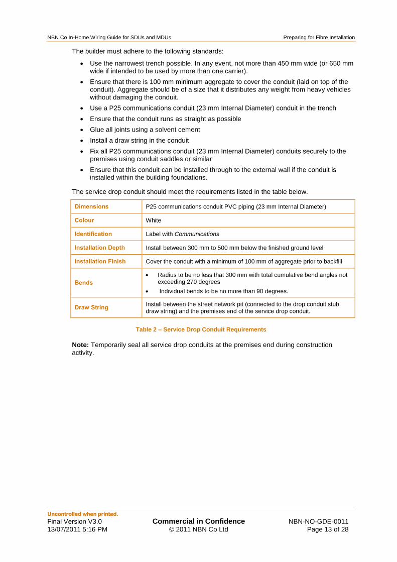
The service drop conduit should meet the requirements listed in the table below.
Dimensions P25 communications conduit PVC piping (23 mm Internal Diameter)
Colour White
Identification Label with Communications
Installation Depth Install between 300 mm to 500 mm below the finished ground level
Installation Finish Cover the conduit with a minimum of 100 mm of aggregate prior to backfill
Bends
Radius to be no less that 300 mm with total cumulative bend angles not exceeding 270 degrees
Individual bends to be no more than 90 degrees.
Draw String Install between the street network pit (connected to the drop conduit stub draw string) and the premises end of the service drop conduit.
Table 2 – Service Drop Conduit Requirements
Note: Temporarily seal all service drop conduits at the premises end during construction activity.

NBN Co In-Home Wiring Guide for SDUs and MDUs Preparing for Fibre Installation
Uncontrolled when printed.
Final Version V3.0 Commercial in Confidence NBN-NO-GDE-0011
13/07/2011 5:16 PM © 2011 NBN Co Ltd Page 14 of 28
Figure 1 – SDU Conduit Installation for Connection to the NBN
300mm radius bends
All CONDUIT FITIINGS MUST BE GLUED.
ORANGE CONDUIT MUST NOT BE USED.
IHf------ 1 x P25 Conduit {builder to supply}
Internal Wall Cavity
Notes 1. Use Rigid White P25 Communications
Conduit ONLY
2. Use no more than 3 x 90° bends between draw points. The bend radius of each bend must be no less than 300mm or more.
Quick Acronyms PCD - Premises Connection Device NTD - Network Termination Device PSU - Power Supply Unit FGL- Finished Ground Level
ZOOM SECTION

NBN Co In-Home Wiring Guide for SDUs and MDUs Preparing for Fibre Installation
Uncontrolled when printed.
Final Version V3.0 Commercial in Confidence NBN-NO-GDE-0011
13/07/2011 5:16 PM © 2011 NBN Co Ltd Page 15 of 28
300-500mm
below FGLFGL
Ground
Footings
To Pit
100 mm aggregate on
top of conduit
Single 300 mm radius bend from
horizontal to vertical alignment
Aggregate
Service Drop Conduit
Fu
ture
Inte
rior
Wa
ll
Fu
ture
Exte
rior
Wa
ll
Temporary Cap
Figure 2 – Service Drop Conduit Installation (in footings option)
5.3 External PCD Installation
NBN Co will installation a PCD on the exterior of the premises.
External Space Requirement
300 mm wide
300 mm tall
100 mm deep
Installation Height 710 mm to 1500 mm (from top of PCD)
Distance Between Cable Entry ports
100 mm minimum to 140 mm maximum
Table 3 – PCD Installation Requirements
The PCD requires a minimum space of 300 mm high x 300 mm wide x 100 mm deep and is located directly above the end of the service drop conduit. A P25 (23 mm ID) conduit is extended from this same location directly to the internal communications (Home Distributor) cabinet.

NBN Co In-Home Wiring Guide for SDUs and MDUs Preparing for Fibre Installation
Uncontrolled when printed.
Final Version V3.0 Commercial in Confidence NBN-NO-GDE-0011
13/07/2011 5:16 PM © 2011 NBN Co Ltd Page 16 of 28
Figure 3 – Example Premises Connection Device
Important
NBN Co has the right to request re-work from the builder if, due to these standards not being met, faults or undesirable behaviour occurs in the fibre-based telecommunications equipment.
5.4 Internal Communications Cabinet (Home Distributor)
This section covers the installation of the internal communications cabinet (Home Distributor).
The aim of the Home Distributor is to:
Protect wiring and equipment from interference and damage
Protect people and animals from the equipment
Provide a professional and aesthetically-pleasing facility for homeowners in which to house the equipment.
5.4.1 Home Distributor Installation
The Home Distributor cabinet may be utilised as both the NBN Co communications cabinet and the internal premises wiring cabinet.
To assure an aesthetically-pleasing installation, the Home Distributor cabinet may be embedded into an internal wall. The Home Distributor cabinet requires ventilation holes around the edges of the Home Distributor cabinet to allow heat dissipation into the wall cavity (or alternatively, into the room).
The NTD, PSU, standard telecommunications outlet and premises wiring panels can all be housed within the Home Distributor cabinet. This may also require the installation of active equipment by the building owner.
A 240V powerpoint (GPO) must be installed by the builder within the Home Distributor cabinet.

NBN Co In-Home Wiring Guide for SDUs and MDUs Preparing for Fibre Installation
Uncontrolled when printed.
Final Version V3.0 Commercial in Confidence NBN-NO-GDE-0011
13/07/2011 5:16 PM © 2011 NBN Co Ltd Page 17 of 28
Figure 4 – Example Home Distributor Layout for SDU and MDU buildings
Internal wiring is installed within the Home Distributor cabinet. NBN Co recommends that cabling to wall outlets is a minimum of Category 6.
The builder is responsible for the termination of the premises wiring either onto the patch panels or into the building owner equipment.
Installation Dimensions
(for access and ventilation)
600 mm wide
450 mm tall
120 mm deep (part can be embedded in the wall)
900 mm free working space in front of cabinet
(Additional space is required if a customer wiring patch panel is collocated within the cabinet)
Installation Height Between 800 mm and 1700 mm above the finished ground level from the top of the cabinet
Table 4 – Home Distributor Requirements

NBN Co In-Home Wiring Guide for SDUs and MDUs Preparing for Fibre Installation
Uncontrolled when printed.
Final Version V3.0 Commercial in Confidence NBN-NO-GDE-0011
13/07/2011 5:16 PM © 2011 NBN Co Ltd Page 18 of 28
5.4.2 Internal Space Requirements
PSUNTD
FWO
25
65 301
79
76
380
117 110
70
218
520
25182
25
12
51
35
Floor level
80
0 m
in. 1
70
0 m
ax.
All dimensions are in millimetres
Note:-
GPO not supplied by NBN Co.
NT
D
PS
U
FW
O
40
120
50
(Min)
Figure 5 – Internal Space Clearance Requirements
The layout shown above (Figure 5 – Internal Space Clearance Requirements) details the clearances required between devices and can change to suit selected Home Distributor cabinet dimensions.
5.4.3 Internal Communications Premises Wiring
Figure 6 – In-House Wiring Diagram
~-1
~ r
....
IN-HOUSE WIRING DIAGRAM
Home Distributor (Boilder iOinstall)
rn ,,E . J
GPO
Telephone
'--lt:l.alle0C0I Bedroom'
Kitchen•
Study'
External Wall
'"'""'" Power Cabling
Phone/Data Outlet (RJ45)
- Cat 6 Cabling
Phone Outlet (RJ11 )
- Cat 6t Cabling (RJ11)
1001 Modular Socket
1001 Power Outlet
c:::J Builder to install c:::J NBN to install - NBN provided Cabling == P25 Conduit (Builder to install)
Each modular AJ45 socket may be used for voice or data connections, AJll /12 supports voice connection only. Supplementary access may be prov•ded using cordless/wireless technologies.
Your internet data service is supplied from the NTD using a standard Ethernet 10/l OOMbps (1 0/100Base·T) connection. A modem is not required but the use of a router or gateway device is recommended.
'Suggested zones onty. 1NBN ~
Quick Acronyms PCD- Premises Connection Device NTD - Network Termination Device PSU - Power Supply Unit

NBN Co In-Home Wiring Guide for SDUs and MDUs Preparing for Fibre Installation
Uncontrolled when printed.
Final Version V3.0 Commercial in Confidence NBN-NO-GDE-0011
13/07/2011 5:16 PM © 2011 NBN Co Ltd Page 19 of 28
For data services to be simultaneously available at multiple locations, the Home Distributor cabinet requires the installation of active equipment (a switch, hub or similar). The NTD and PSU must to be located within, the Home Distributor cabinet.
The NTD presents four RJ45 data ports and two voice ports. If the building owner requires data and/or voice services to present at multiple locations within the building, the provision of a centralised premises wiring, active equipment (a switch, hub or similar) and patch panel installed (in addition to the Home Distributor cabinet) is required.
Note: Each service supplied to the premises can only be presented at a single NTD port (UNI – User Network Interface). The NTD is not designed to hub, switch or otherwise reproduce traffic across multiple NTD ports, so cannot provide simultaneous connectivity to multiple locations in the house without additional active equipment (a switch, hub or similar).
Note: NBN Co does not provide the Home Distributor cabinet, active equipment or customer wiring.
NBN Co recommends the cabling connection between the NBN Co NTD and the Home Distributor cabinet should have (at a minimum) two Category 6 cables installed, one for data and one for voice.
5.4.4 Data Cable Wiring (builder to supply)
T568A
Pair 1
1 2 3 4 5 6 7 8
Pair 3
Pair 2
Pair 4
TIA/EIA 568 Wiring
White and Green
Brown
White and Brown
Orange
White and Blue
Blue
White and Orange
Green
1
7
6
5
4
3
2
8
Figure 7 – 8P8C (RJ45) Data Cable Wiring
The data connection between the building owner equipment and the NTD requires the building owner to provide Category 6 patch-cord(s) and/or cable(s) depending on desired configuration wired to TIA/EIA 568A standard as shown in Figure 7 – 8P8C (RJ45) Data Cable Wiring .
The builder is to ensure that the installed cable and terminations meet the expected performance standards as per the manufacturer‟s recommendations.
Data cable(s) must terminate with an RJ45 (8P8C) plug following the TIA/EIA 568A wiring standard (refer to Figure 7 – 8P8C (RJ45) Data Cable Wiring ) at the NTD location, with sufficient length to allow for connection into the NTD.
Data cable(s) must be labelled at both ends with a minimum of, UNI-D1 [D2, D3, D4] and any other relevant information.
For general wiring information, refer to the various wiring guides supplied at: http://www.smartwiredhouse.com.au/.

NBN Co In-Home Wiring Guide for SDUs and MDUs Preparing for Fibre Installation
Uncontrolled when printed.
Final Version V3.0 Commercial in Confidence NBN-NO-GDE-0011
13/07/2011 5:16 PM © 2011 NBN Co Ltd Page 20 of 28
5.4.5 Voice Cable Wiring (builder to supply)
The cable must be labelled at the both ends with UNI-V1 [V2].
The voice connection required between the building owner equipment and the NTD requires the building owner to provide suitable patch-cord(s) and/or cable(s) for connection into the UNI-V port(s) (RJ11) terminated as shown below (Figure 8 – 6P4C (RJ11) Voice Cable Wiring).
AS/ACIF S009
(6P4C)
Pair 1
1 2 3 4 5 6
Pair 2
AS/ACIF S009 Wiring
Orange (Aux)
White and Blue (L+ or Tip)
Blue (L- or Ring)
White and Orange (Earth)5
4
3
2
1
6
Not used
Not Used
(6P4C)
Outer contacts are not fitted in NBN NTD
Figure 8 – 6P4C (RJ11) Voice Cable Wiring
For general wiring information, refer to the various wiring guides supplied at: http://www.smartwiredhouse.com.au/.
5.4.6 PSU AC Power Requirements
The fibre telecommunications equipment (specifically, the PSU) requires connection to the building mains 240V power to function.
The builder must:
Install a single 240V powerpoint. Ensure it is collocated within 1.5 metres of the PSU.
Note: The installation of a dual 240V powerpoint is recommend if it will be used to power a home gateway / hub device.
Fit the powerpoint with a removable NBN PSU label
Ensure all 240V electrical cables associated with the PSU installation meet the requirements of AS/NZS 3000:2007 (see Appendix C – Australian and International Standards)
Maintain all cable separations according to AS/ACIF S009:2006 (or the latest issue at time of installation).

NBN Co In-Home Wiring Guide for SDUs and MDUs Preparing for Fibre Installation
Uncontrolled when printed.
Final Version V3.0 Commercial in Confidence NBN-NO-GDE-0011
13/07/2011 5:16 PM © 2011 NBN Co Ltd Page 21 of 28
5.4.7 PSU Installation Requirements
Space Requirements
(for access and ventilation if not installed in an internal communications cabinet)
30 mm around the sides of the PSU
Installation Height Between 700 mm and 1700 mm measured from finished ground level to the top of the PSU.
Distance from the NTD Internal NTD: Less than 3 metres radial
Environmental Restrictions
Position away from windows, direct sunlight, sources of water, sources of heat, work areas, areas prone to physical damage, areas prone to high humidity, areas prone to high dust.
The selected location must provide for air circulation and minimise physical intrusion into the installation space (for example curtains and furniture).
Suggested Locations
The PSU should be located within the Home Distributor near the NTD
Enclosed garage, or a garage under the main roof, where the ambient temperature will not exceed 40 degrees Celsius.
Study
Lounge
Rumpus room.
Table 5 – PSU Installation Requirements
NBN Co In-Home Wiring Guide for SDUs and MDUs Multi Dwelling Units
Uncontrolled when printed.
Final Version V3.0 Commercial in Confidence NBN-NO-GDE-0011
13/07/2011 5:16 PM © 2011 NBN Co Ltd Page 22 of 28
6 Multi Dwelling Units
NBN Co requirements for equipment within MDU end-user premises are typically the same as the methods already described. The section provides the application of these installation requirements with respect to the various types of MDUs.
For the purpose of this document, NBN Co has split them into two categories:
External Cable Feed MDUs
Internal Cable Feed MDUs.
6.1 External Cable Feed MDUs
These categories are similar to SDUs in that the connection to the premises is via an external underground conduit into each individual end-user premises. For more information, refer to the Service Drop Conduit Installation section in this document on page 12.
An example of this type of MDU would be a row of Villas or Townhouses.
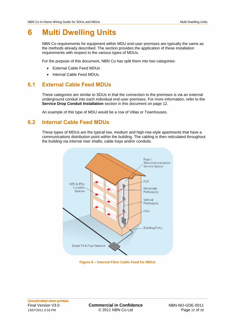
6.2 Internal Cable Feed MDUs
These types of MDUs are the typical low, medium and high-rise-style apartments that have a communications distribution point within the building. The cabling is then reticulated throughout the building via internal riser shafts, cable trays and/or conduits.
Figure 9 – Internal Fibre Cable Feed for MDUs

NBN Co In-Home Wiring Guide for SDUs and MDUs Multi Dwelling Units
Uncontrolled when printed.
Final Version V3.0 Commercial in Confidence NBN-NO-GDE-0011
13/07/2011 5:16 PM © 2011 NBN Co Ltd Page 23 of 28
Figure 10 – Networking Diagram for MDUs
„

NBN Co In-Home Wiring Guide for SDUs and MDUs Multi Dwelling Units
Uncontrolled when printed.
Final Version V3.0 Commercial in Confidence NBN-NO-GDE-0011
13/07/2011 5:16 PM © 2011 NBN Co Ltd Page 24 of 28
For more information on MDU design and requirements, refer to the NBN Co document, New Developments MDU - Building Design Requirements v1.0. This can be found on the NBN Co website.
Cable Pathway Type
23mm nominal internal diameter rigid communications conduit
Cable tray
Duct (other than rigid conduit)
Catenary
Table 6 – Cable Pathway Type
As the fibre will be fed directly to an internal point within each unit, an internal communication cabinet (Home Distributor cabinet) must be utilised.
For more information on clearances, refer to section 5.4.

NBN Co In-Home Wiring Guide for SDUs and MDUs Post Building Completion Installation
Uncontrolled when printed.
Final Version V3.0 Commercial in Confidence NBN-NO-GDE-0011
13/07/2011 5:16 PM © 2011 NBN Co Ltd Page 25 of 28
7 Post Building Completion Installation
7.1 Installation Connection Delays
Important
Failure to comply with this document may result in delays in connecting the premises to the National Broadband Network or result in NBN Co‟s inability to make a fibre connection to the new premises
Builders, developers and building owners may face delays and additional costs (borne by the owner of the premises) until the building preparations are brought into compliance with these guidelines.
7.2 Connection Problems
Where unforeseen circumstances lead to the construction of a building unable to connect to the fibre-based telecommunications network, building owners should contact the Access Seeker to facilitate service activation.
The Access Seeker will then contact NBN Co to determine the appropriate remediation and arrange installation and connection to the fibre communications network.
The building owner may incur additional charges where remediation work is required.
7.3 Installation of the Fibre Equipment
At any point after the builder has completed all preparatory installations (as described previously) and prior to building hand-over to the building owner, NBN Co can be contacted to arrange for installation of the fibre equipment.
Note: Not only must the builder have completed all preparatory installations, but the building must have reached lock-up stage.
Site access will be arranged with the builder. The following actions are then undertaken by NBN Co:
Installation of the PCD, NTD and the PSU
Installation of the service drop cable fibre from the street pit to the NTD, through the service drop conduit
Connection of any customer wiring presented at the NTD location (clearly labelled), to the NTD User Network Interface(s).
Verification of correct operation up to and including the NTD and PSU is conducted as part of the installation.
No verification of correct internal customer wiring is conducted.
Note: If services at distributed outlets are subsequently found to be faulty, the cost of remedying any wiring defects on the end user-side of the network boundary is a matter for the building owner and / or end user.

NBN Co In-Home Wiring Guide for SDUs and MDUs Appendix A – Key Terms
Uncontrolled when printed.
Final Version V3.0 Commercial in Confidence NBN-NO-GDE-0011
13/07/2011 5:16 PM © 2011 NBN Co Ltd Page 26 of 28
8 Appendix A – Key Terms
Term Description
Access Seeker A customer acquiring NBN Co wholesale services to supply services to Retail Service Providers (RSPs), Wholesale Service Providers (WSPs) or end users.
FTTP
Fibre to the Premises FTTP uses optical fibre cables reaching all the way to the Premises, with Gigabit Passive Optical Network (GPON) fibre-sharing.
FTTP solution provider Any company or supplier supplying fibre to the premises.
IPTV
Internet Protocol Television
A service where video streams are delivered across Internet technology instead of traditional radiofrequency broadcast transmission for viewing at an end user premises.
MDU
Multiple Dwelling Unit Buildings that contain more than one dwelling unit. These can range from duplexes to 200+ unit apartment blocks.
NBN National Broadband Network.
NBN Co Company established by the Australian Government to design, build and operate the wholesale-only National Broadband Network (NBN).
New Developments New real estate developments. Formerly “Greenfields”.
NTD
Network Termination Device
NBN Co‟s network termination point at each premises, for residential fibre services (typically) featuring 4 data and 2 voice interfaces.
FWO Fibre Wall Outlet
PCD
Premises Connection Device
A unit to terminate the service drop cable to the side of the premises.
PCP Premises Connection Points.
PSU A power supply unit, which provides power to the NTD.
SDU
Single Dwelling Unit Premises containing only one dwelling unit.
UNI
User Network Interface The physical port on the NBN Co NTD at the end user premises, which connects the end user‟s residential gateway, Ethernet enabled device or telephone to the NBN.

NBN Co In-Home Wiring Guide for SDUs and MDUs Appendix B – Activity Matrix
Uncontrolled when printed.
Final Version V3.0 Commercial in Confidence NBN-NO-GDE-0011
13/07/2011 5:16 PM © 2011 NBN Co Ltd Page 27 of 28
9 Appendix B – Activity Matrix
The following shows the installation life-cycle of fibre telecommunication equipment in New Developments. Highlighted (in orange) is the section that this document encompasses.
Activity Responsible Party Timing
Installation of estate pit and conduit Estate Developer Prior to building commencement
Installation of estate fibre FTTP solution provider Prior to building commencement
Connection of estate fibre to the NBN FTTP solution provider Prior to building commencement
Installation of the service drop conduit stub
FTTP solution provider Prior to building commencement
Building design to accommodate fibre equipment and wiring
Builder Prior to building commencement
Installation of the service drop conduit and draw-string
Builder During base / slab stage
Installation of the Home Distributor Builder During frame / wall construction
Installation of power to the PSU location
Builder During building wiring
Installation of PSU conduit Builder During building wiring
Installation of customer wiring conduit Builder During building wiring
Installation of pre-wired customer wiring
Builder / Owner During building wiring
Installation of NTD NBN Co After lock-up stage
Installation of PSU NBN Co After lock-up stage ...and when mains power to the premises has been connected and turned on
Installation of PSU wiring NBN Co After lock-up stage
Installation of PCD NBN Co After lock-up stage
Installation of FWO NBN Co After lock-up stage
Installation of service drop cable fibre to PCD
NBN Co After lock-up stage
Connection of service drop cable fibre from PCD to NTD
NBN Co After lock-up stage
Connection of PSU wiring to NTD NBN Co After lock-up stage
Connecting pre-wired customer wiring to NTD
Owner / Service Provider After lock-up stage
Activation of communication services Owner / Service Provider After order from RSP received
Installation of additional customer wiring (optional)
Owner As required during or after building construction
Connection of additional customer wiring to NTD (optional)
Owner As required during or after building construction

NBN Co In-Home Wiring Guide for SDUs and MDUs Appendix C – Australian and International Standards
Uncontrolled when printed.
Final Version V3.0 Commercial in Confidence NBN-NO-GDE-0011
13/07/2011 5:16 PM © 2011 NBN Co Ltd Page 28 of 28
10 Appendix C – Australian and International Standards
For Australian and international cabling standard compliance guidelines, refer to the following documents.
Some of these documents were referred to when writing these guidelines.
Number Title
AS/CA S008:2010 Technical standard on requirements for Authorised Cabling Products
AS/ACIF S009:2006 Installation requirements for customer cabling (communications Wiring Rules)
AS/NZS 3000:2007 Electrical Wiring Rules
AS/NZS 3080 Telecommunications Installations – Cabling Systems for Commercial Premises
AS/NZS 3084 Telecommunications Installations – Telecommunications Pathways and Spaces for Commercial Buildings
AS/NZS 3087 Telecommunications installations - Generic cabling systems - Specification for the testing of balanced communication cabling in accordance with values set out in AS/NZS 3080
EIA/TIA TSB-36 Additional Cable Specifications for UTP Cabling.
EIA/TIA TSB-40 Additional Transmission Specifications for UTP Connecting Hardware.
EIA/TIA 568-A Commercial Building Telecommunications Wiring Standard.
EIA/TIA TSB-67 Transmission Performance Specifications for Field Testing of UTP Cabling Systems.
EIA/TIA TSB-75 Additional Horizontal Cabling Practice for Open Offices.
BICSI TDMM Telecommunications Distribution Methods Manual
HB252:2007 Communications Cabling Manual module 3: Residential Communications Cabling Handbook


