
NC STATE UNIVERSITY
Outline • Background • Passive Intermodulation Distortion (2 parts)
– Part 1, PIM effects, Electro-Thermal PIM • Test Equipment, Microwave Circuits / Antennas
– Part 2, PIM effects • Non Electro-Thermal PIM, Filter PIM
• Behavioral Modeling – Behavioral model – Measurement Equipment
• Simulation and Modeling of Large Systems – Part 1, New circuit concepts – Part 2, fREEDA
1
NC STATE UNIVERSITY
Fundamental Problem of Science and Engineering being Addressed
• How do we design a broad band low passive intermod (PIM) system? • How do we design a broadband high power circuit that does not
require filters or isolators? • How do we design waveforms to uniquely identify devices and also
mitigate the effects of PIM. • How do we cancel interfering signals from our receiver so that we
maximize identifiability of return signals. • How do we design broadband compact antenna arrays? • How can we develop forensics that will enable devices to be identified
by model type and design revision? • How can we maximize the coupling of RF signals on a wire-on-
ground and consequently maximize indentifiability,
2
NC STATE UNIVERSITY NC STATE UNIVERSITY
Passive Intermodulation Distortion, Part 1
Michael Steer with Jonathan Wilkerson
3
NC STATE UNIVERSITY
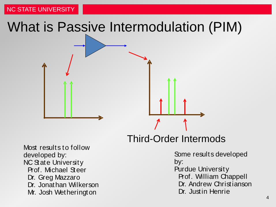
What is Passive Intermodulation (PIM)
4
Third-Order Intermods Some results developed by: Purdue University Prof. William Chappell Dr. Andrew Christianson Dr. Justin Henrie
Most results to follow developed by: NC State University Prof. Michael Steer Dr. Greg Mazzaro Dr. Jonathan Wilkerson Mr. Josh Wetherington
NC STATE UNIVERSITY
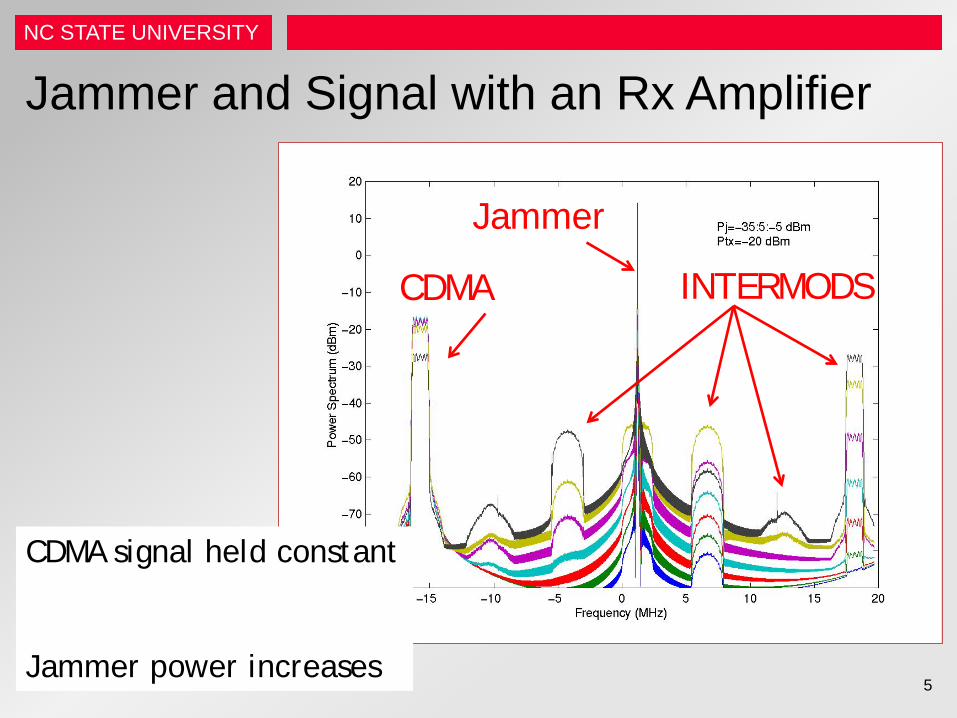
Jammer and Signal with an Rx Amplifier
Jammer
CDMA INTERMODS
CDMA signal held constant Jammer power increases
5
NC STATE UNIVERSITY
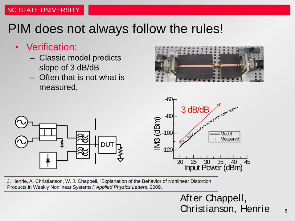
PIM does not always follow the rules! • Verification:
– Classic model predicts slope of 3 dB/dB
– Often that is not what is measured,
20 25 30 35 40 45
-120
-100
-80
-60
Model Measured
IM3
(dBm
)Input Power (dBm)
3 dB/dB
DUT
After Chappell, Christianson, Henrie
J. Henrie, A. Christianson, W. J. Chappell, “Explanation of the Behavior of Nonlinear Distortion Products in Weakly Nonlinear Systems,” Applied Physics Letters, 2009.
6
NC STATE UNIVERSITY
PIM • Suggested sources of PIM include:
– Dirty contacts and surface roughness – Thermal self heating effects – Tunneling through oxides between contacts – Ferromagnetic materials
• All of the above can exist in theory but which ones are the ones to worry about.
• Lots of theoretical analyses but few experimental results. – And that is because …
• Isolating and verifying individual physical sources of PIM is difficult.
• In SIAMES we showed that – PIM is primarily a current-based effect – Ferromagnetic effects can be significant if there are ferrous metals – Electro-thermal PIM is the fundamental limit.
7
NC STATE UNIVERSITY
Where we are going . . . • Two types of PIM
– Nonlinear PIM • Current-based • Ferromagnetic effects are important if there are ferrous metals
present • Electrothermally-induced PIM is the fundamental limit
– Linear PIM • Comes from energy storage
– Filters, reactive elements
8
NC STATE UNIVERSITY
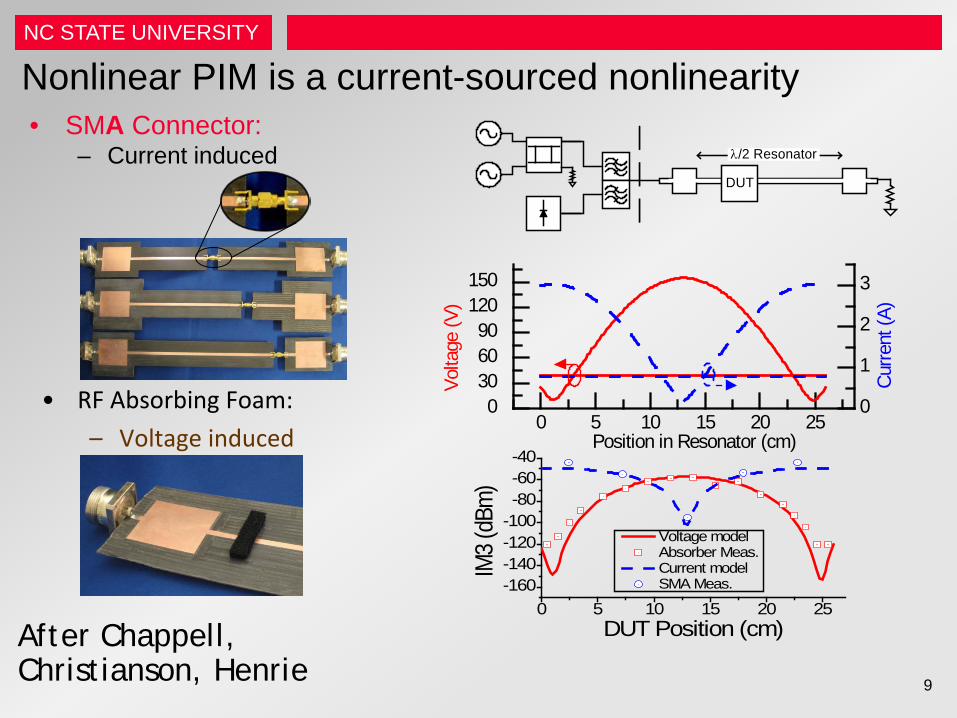
Nonlinear PIM is a current-sourced nonlinearity
DUT
λ/2 Resonator
0 5 10 15 20 250
306090
120150
0
1
2
3
Volta
ge (V
)Position in Resonator (cm)
Cur
rent
(A)
0 5 10 15 20 25-160-140-120-100-80-60-40
Voltage model Absorber Meas. Current model SMA Meas.
IM3 (
dBm)
DUT Position (cm)
• SMA Connector: – Current induced
• RF Absorbing Foam: – Voltage induced
After Chappell, Christianson, Henrie
9
NC STATE UNIVERSITY
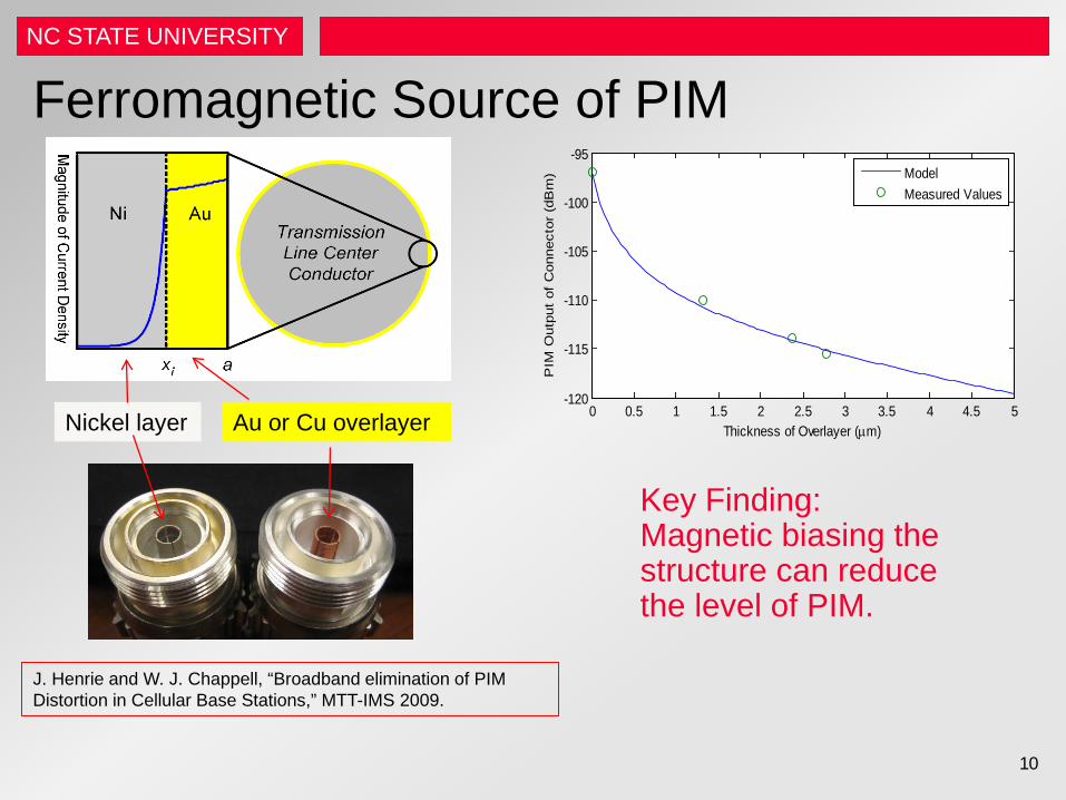
Ferromagnetic Source of PIM
Nickel layer Au or Cu overlayer 0 0.5 1 1.5 2 2.5 3 3.5 4 4.5 5-120
-115
-110
-105
-100
-95
Thickness of Overlayer (µm)
PIM
Out
put
of C
onne
ctor
(dB
m)
ModelMeasured Values
J. Henrie and W. J. Chappell, “Broadband elimination of PIM Distortion in Cellular Base Stations,” MTT-IMS 2009.
Key Finding: Magnetic biasing the structure can reduce the level of PIM.
10
NC STATE UNIVERSITY
Close-in PIM Measurement Systems • Four developed at NC State
– Walker (Aaron Walker) – Hu (Jie Hu) – Wilkerson (Jonathan Wilkerson) – Wetherington (Josh Wetherington)
• <update of Wilkerson >
11
NC STATE UNIVERSITY
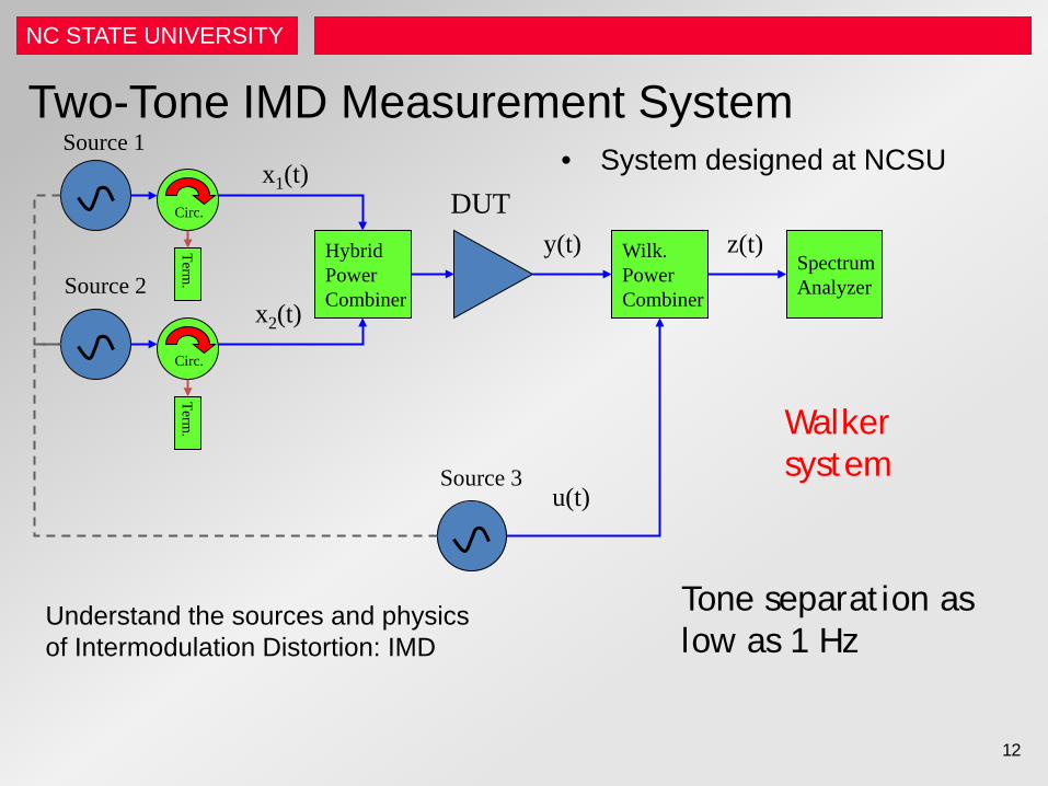
Two-Tone IMD Measurement System • System designed at NCSU
Spectrum Analyzer
Hybrid Power Combiner
Circ.
Circ.
Term.
Term.
Wilk. Power Combiner
Source 1
Source 2
Source 3
DUT x1(t)
x2(t)
y(t)
u(t)
z(t)
Understand the sources and physics of Intermodulation Distortion: IMD
Tone separation as low as 1 Hz
12
Walker system
NC STATE UNIVERSITY
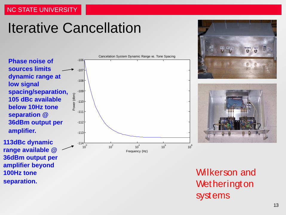
Iterative Cancellation
13
Wilkerson and Wetherington systems
100
102
104
106
108
-114
-113
-112
-111
-110
-109
-108
-107
-106Cancelation System Dynamic Range vs. Tone Spacing
Pow
er (d
bm)
Frequency (Hz)
Phase noise of sources limits dynamic range at low signal spacing/separation, 105 dBc available below 10Hz tone separation @ 36dBm output per amplifier.
113dBc dynamic range available @ 36dBm output per amplifier beyond 100Hz tone separation.
NC STATE UNIVERSITY
14
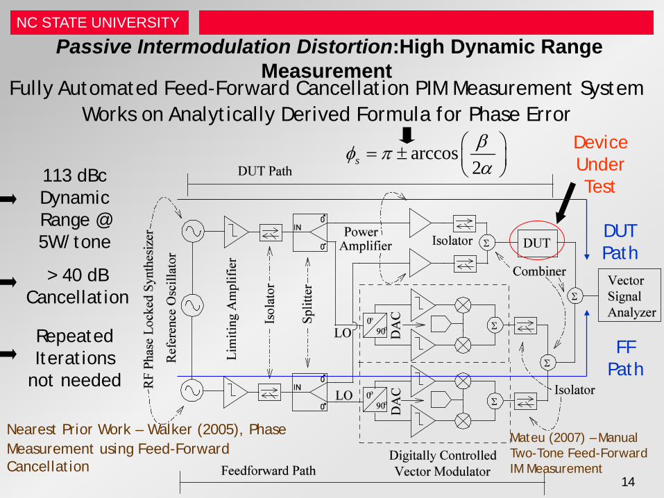
Passive Intermodulation Distortion:High Dynamic Range Measurement
Nearest Prior Work – Walker (2005), Phase Measurement using Feed-Forward Cancellation
Fully Automated Feed-Forward Cancellation PIM Measurement System Works on Analytically Derived Formula for Phase Error
113 dBc Dynamic Range @ 5W/tone
> 40 dB Cancellation
arccos2sβφ πα
= ±
Repeated Iterations
not needed
Device Under Test
DUT Path
FF Path
Mateu (2007) – Manual Two-Tone Feed-Forward IM Measurement
NC STATE UNIVERSITY
15
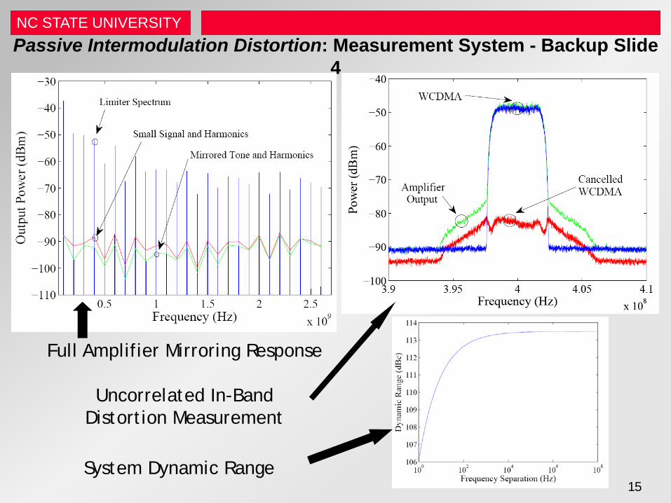
Passive Intermodulation Distortion: Measurement System - Backup Slide 4
Uncorrelated In-Band Distortion Measurement
System Dynamic Range
Full Amplifier Mirroring Response
NC STATE UNIVERSITY
16
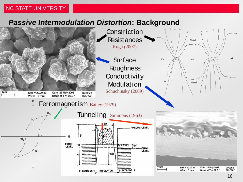
Passive Intermodulation Distortion: Background How can we model electro-thermal conductivity modulation?
Ferromagnetism Bailey (1979)
Constriction Resistances
Kuga (2007)
Surface Roughness
Conductivity Modulation
Schuchinsky (2009)
Tunneling Simmons (1963)
NC STATE UNIVERSITY
17
• PIM was first reported [Chapman (1973,1976)]: – In the 1960’s under the Hull noise program for the NELC – In satellite systems (contacts in cavity backed antennas) by MIT Lincoln
Labs in 1968 on LES-5 – In waveguides and flange joints by R. Cox in 1970 – Measurements were extended to transmission lines and connectors by
Bayrak in 1975 – Recently has become important in cellular base-stations [Macchiarella
(2004)] • High power, sensitive receive-transmit systems require isolations from
150-200 dB for operation – Intermodulation Distortion from passive components can exceed this range
significantly (ex: Cox (1970), -25 dBm in waveguides at 1 Watt) • Empirical data and workarounds for PIM on many different microwave
components exist, but there are no verified physical models (Communications with Taconic, Harris Corporation, I2WD, ARL)
Passive Intermodulation Distortion: Background 1
NC STATE UNIVERSITY
18
• Passive Intermodulation Distortion Effects – Reduces Signal to Interference Ratio and limits coverage areas,
bandwidth, and capacity [Eng (1991), Jargon (1998)] – Need ways to reduce or eliminate PIM
• Passive Intermodulation Distortion Mechanisms – Large number of difficult to separate PIM producing mechanisms [Lui
(1990), Huan (2003)] – Need to know what mechanisms cannot be removed by “proper”
design techniques • Passive Intermodulation Distortion Modeling
– Currently processes are grouped into behavioral models – Physical models are needed to facilitate low PIM design
• Passive Intermodulation Distortion Measurement – Current Wideband Measurements Systems: 75 dBc (Agilent) – Dynamic Range required for PIM measurement: 100 to 160 dBc
Passive Intermodulation Distortion: Background
NC STATE UNIVERSITY
19
Passive Intermodulation Distortion: Background
Measurement systems using filters and feed-forward cancellation have been built… Extended dynamic range of two-tone automated feed-forward measurement system to 113 dBc for PIM measurement
Electro-Thermal coupling has been studied as an average phenomena in RF signals due to the time constant difference…
Showed that electrical responses exhibit non-integer order Laplacian behavior due to coupling between electrical and thermal domains
Parsons (1994), Deats (1997), Rubiola (2002), Mateu (2007)
Batty (2000), Snowden(2001), Zoltan (2002), Parker(2005)
NC STATE UNIVERSITY
20
Passive Intermodulation Distortion: Background Passive lumped components have been thermally modeled but lack physical descriptions of electrical distortion from electrical and thermal coupling… Provided an analytic and approximate physical model for electro-thermal passive intermodulation in lossy lumped components that accounts for non-integer order behavior PIM in distributed structures has been qualitatively measured and modeled behaviorally but not linked to physical mechanisms…
Isolated electro-thermal conductivity through manufacturing and provided a physically based analytic model for distributed structures that accounts for non-integer order behavior
PIM in resonant structures has been qualitatively measured and modeled behaviorally through near field measurements but not linked to physical mechanisms other than tunneling on reflector antennas…
Isolated electro-thermal conductivity through manufacturing and provided a physically based analytic model for resonant structures that accounts for non-integer order behavior
Keyes (1969), Joy (1970), Fox (1993), Brodsky (1997), Batty (2000), Zoltan (2002), Becthold (2005)
Bayrak (1975), Wilcox (1976), Kuga (2007), Schuchinsky (2008)
Higa (1975), Sanford (1993), Hoeber (1986), S. Hienonen (2001)

NC STATE UNIVERSITY NC STATE UNIVERSITY
Lumped PIM
NC STATE UNIVERSITY
22
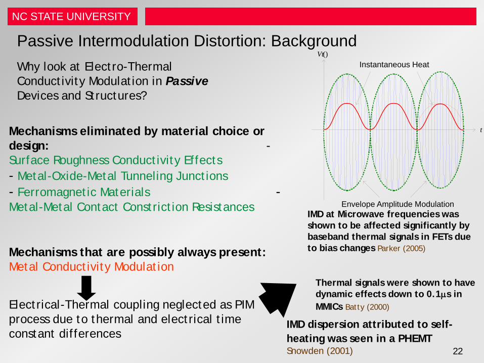
Passive Intermodulation Distortion: Background Why look at Electro-Thermal Conductivity Modulation in Passive Devices and Structures?
Mechanisms eliminated by material choice or design: - Surface Roughness Conductivity Effects - Metal-Oxide-Metal Tunneling Junctions - Ferromagnetic Materials - Metal-Metal Contact Constriction Resistances
Mechanisms that are possibly always present: Metal Conductivity Modulation
Electrical-Thermal coupling neglected as PIM process due to thermal and electrical time constant differences
IMD at Microwave frequencies was shown to be affected significantly by baseband thermal signals in FETs due to bias changes Parker (2005)
Thermal signals were shown to have dynamic effects down to 0.1µs in MMICs Batty (2000)
IMD dispersion attributed to self-heating was seen in a PHEMT Snowden (2001)
t
() Vt
Envelope Amplitude Modulation
Instantaneous Heat
NC STATE UNIVERSITY
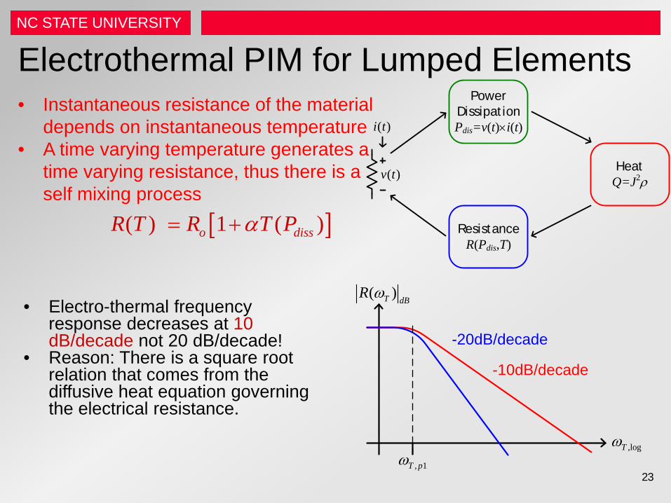
Electrothermal PIM for Lumped Elements • Instantaneous resistance of the material
depends on instantaneous temperature • A time varying temperature generates a
time varying resistance, thus there is a self mixing process
[ ]( ) 1 ( )o dissR T R T Pα= +
PowerDissipationPdis=v(t)×i(t)
HeatQ=J2ρ
ResistanceR(Pdis,T)
( )v t
( )i t
23
• Electro-thermal frequency response decreases at 10 dB/decade not 20 dB/decade!
• Reason: There is a square root relation that comes from the diffusive heat equation governing the electrical resistance.
, 1T pω,logTω
( )T dBR ω
-20dB/decade
-10dB/decade
NC STATE UNIVERSITY
24
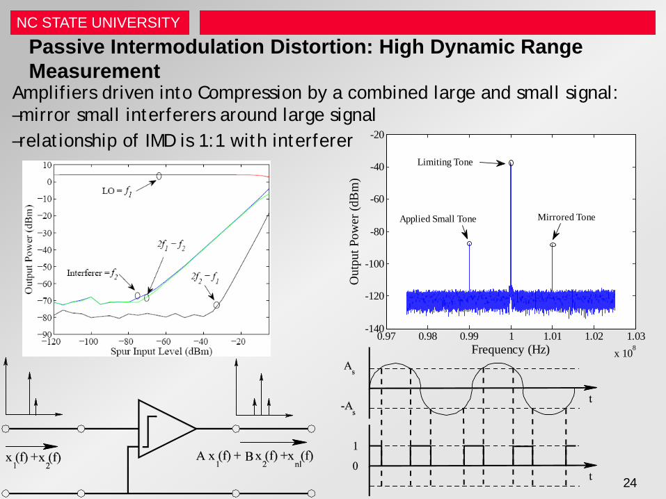
Passive Intermodulation Distortion: High Dynamic Range Measurement
Amplifiers driven into Compression by a combined large and small signal: –mirror small interferers around large signal –relationship of IMD is 1:1 with interferer
0.97 0.98 0.99 1 1.01 1.02 1.03x 10⁸
-140
-120
-100
-80
-60
-40
-20
Frequency (Hz)O
utpu
t Pow
er (d
Bm
)
Limiting Tone
Applied Small Tone Mirrored Tone
NC STATE UNIVERSITY
25
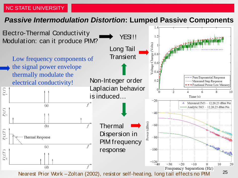
Passive Intermodulation Distortion: Lumped Passive Components
Electro-Thermal Conductivity Modulation: can it produce PIM?
Nearest Prior Work – Zoltan (2002), resistor self-heating, long tail effects no PIM
Low frequency components of the signal power envelope thermally modulate the electrical conductivity! Non-Integer order
Laplacian behavior is induced…
Long Tail Transient
Thermal Dispersion in PIM frequency response
YES!!!
NC STATE UNIVERSITY
26
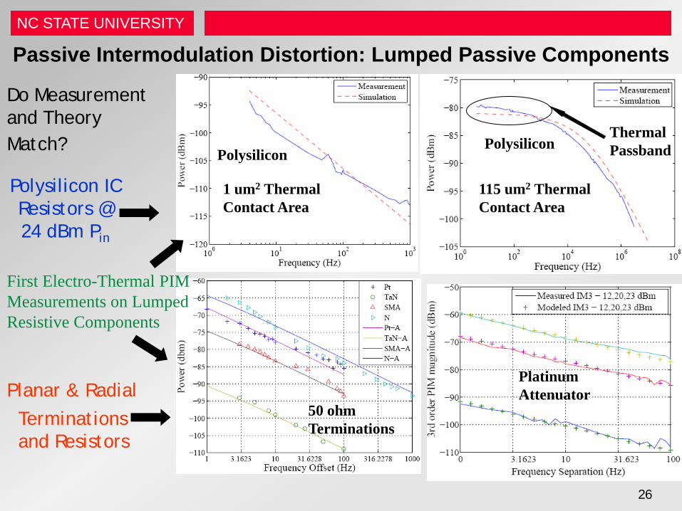
Passive Intermodulation Distortion: Lumped Passive Components
Do Measurement and Theory Match?
Polysilicon IC Resistors @ 24 dBm Pin
First Electro-Thermal PIM Measurements on Lumped Resistive Components
Platinum Attenuator
50 ohm Terminations
1 um2 Thermal Contact Area
115 um2 Thermal Contact Area
Polysilicon Polysilicon
Thermal Passband
Terminations and Resistors
Planar & Radial
NC STATE UNIVERSITY
27
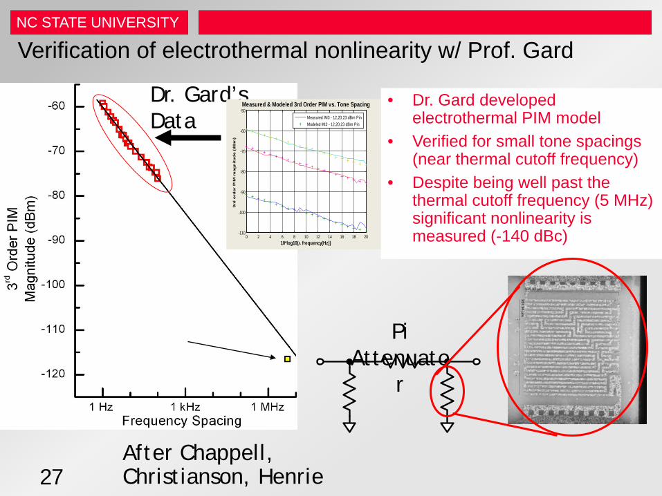
Verification of electrothermal nonlinearity w/ Prof. Gard
• Dr. Gard developed electrothermal PIM model
• Verified for small tone spacings (near thermal cutoff frequency)
• Despite being well past the thermal cutoff frequency (5 MHz) significant nonlinearity is measured (-140 dBc)
Pi Attenuato
r
Dr. Gard’s Data
0 2 4 6 8 10 12 14 16 18 20-110
-100
-90
-80
-70
-60
-50
10*log10(∆ frequency(Hz))
3rd
ord
er
PIM
mag
nit
ud
e (
dB
m)
Measured & Modeled 3rd Order PIM vs. Tone Spacing
Measured IM3 - 12,20,23 dBm PinModeled IM3 - 12,20,23 dBm Pin
After Chappell, Christianson, Henrie

NC STATE UNIVERSITY NC STATE UNIVERSITY
Distributed PIM
NC STATE UNIVERSITY
29
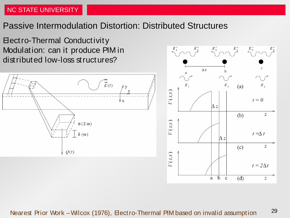
Passive Intermodulation Distortion: Distributed Structures Electro-Thermal Conductivity Modulation: can it produce PIM in distributed low-loss structures?
Nearest Prior Work – Wilcox (1976), Electro-Thermal PIM based on invalid assumption
NC STATE UNIVERSITY
30
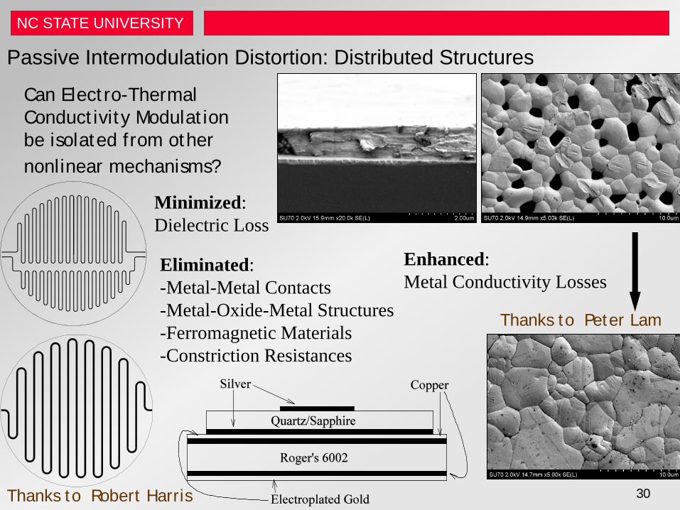
Passive Intermodulation Distortion: Distributed Structures
Can Electro-Thermal Conductivity Modulation be isolated from other nonlinear mechanisms?
Thanks to Peter Lam
Thanks to Robert Harris
Eliminated: -Metal-Metal Contacts -Metal-Oxide-Metal Structures -Ferromagnetic Materials -Constriction Resistances
Enhanced: Metal Conductivity Losses
Minimized: Dielectric Loss
NC STATE UNIVERSITY
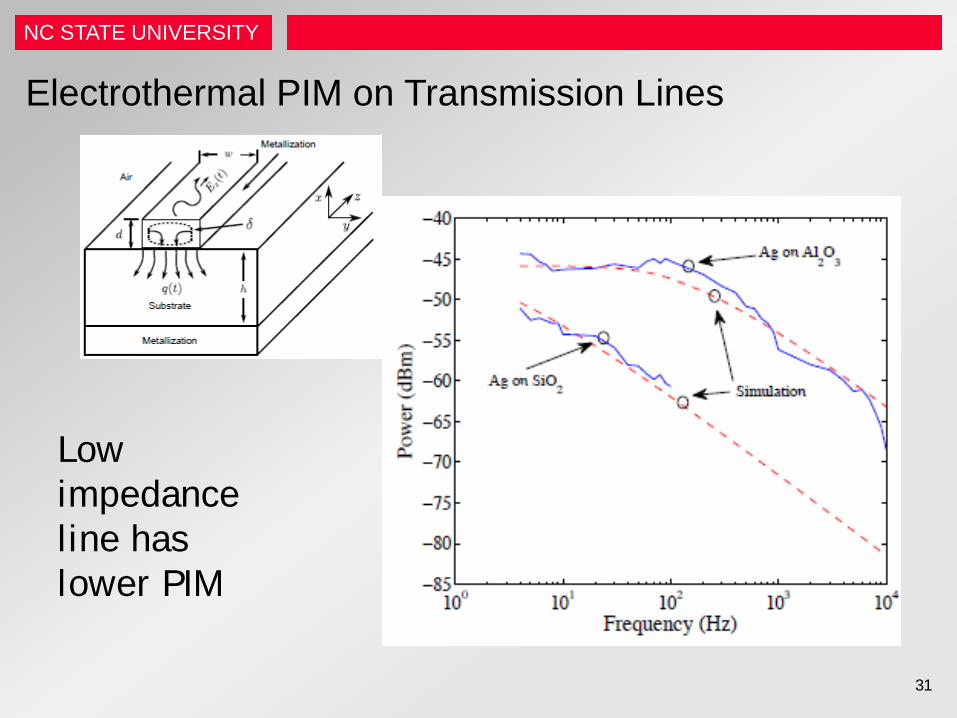
Electrothermal PIM on Transmission Lines
Low impedance line has lower PIM
31
NC STATE UNIVERSITY
32
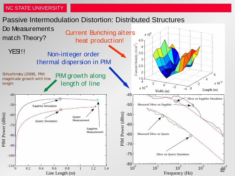
Passive Intermodulation Distortion: Distributed Structures Do Measurements match Theory?
100 101 102 103 104-80
-75
-70
-65
-60
-55
-50
-45
Frequency (Hz)
PIM
Pow
er (d
Bm
)
Silver on Sapphire Simulation
Measured Silver on Sapphire
Measured Silver on Quartz
Silver on Quartz Simulation
0 0.2 0.4 0.6 0.8 1 1.2 1.4-110
-100
-90
-80
-70
-60
-50
-40
PIM
Pow
er (d
Bm
)
Line Length (m)
Sapphire Simulation
Quartz SimulationQuartzMeasurement
SapphireMeasurement
PIM growth along length of line
Current Bunching alters heat production!
Non-integer order thermal dispersion in PIM
YES!!!
Schuchinsky (2008), PIM magnitude growth with line length
NC STATE UNIVERSITY
33
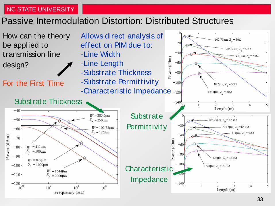
Passive Intermodulation Distortion: Distributed Structures How can the theory be applied to transmission line design?
Allows direct analysis of effect on PIM due to: -Line Width -Line Length -Substrate Thickness -Substrate Permittivity -Characteristic Impedance
Substrate Thickness
Substrate Permittivity
Characteristic Impedance
For the First Time

NC STATE UNIVERSITY NC STATE UNIVERSITY
Resonant PIM
NC STATE UNIVERSITY
35
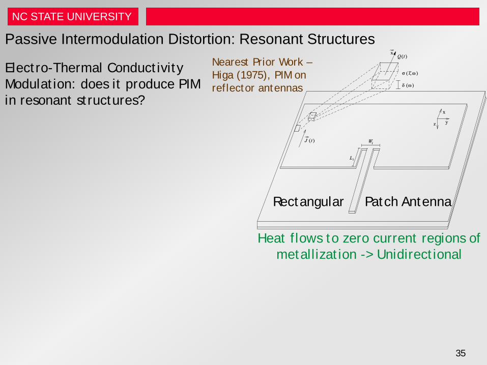
Passive Intermodulation Distortion: Resonant Structures
Electro-Thermal Conductivity Modulation: does it produce PIM in resonant structures?
Heat flows to zero current regions of metallization -> Unidirectional
Nearest Prior Work – Higa (1975), PIM on reflector antennas
Rectangular Patch Antenna
NC STATE UNIVERSITY
36
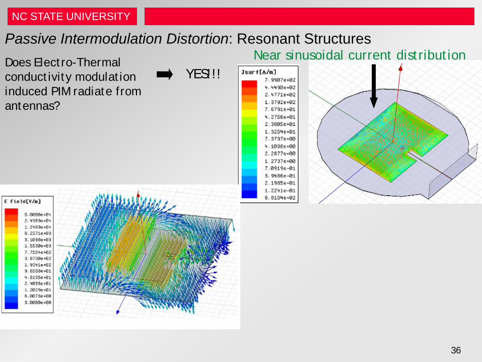
Passive Intermodulation Distortion: Resonant Structures Does Electro-Thermal conductivity modulation induced PIM radiate from antennas?
Near sinusoidal current distribution YES!!!
NC STATE UNIVERSITY
37
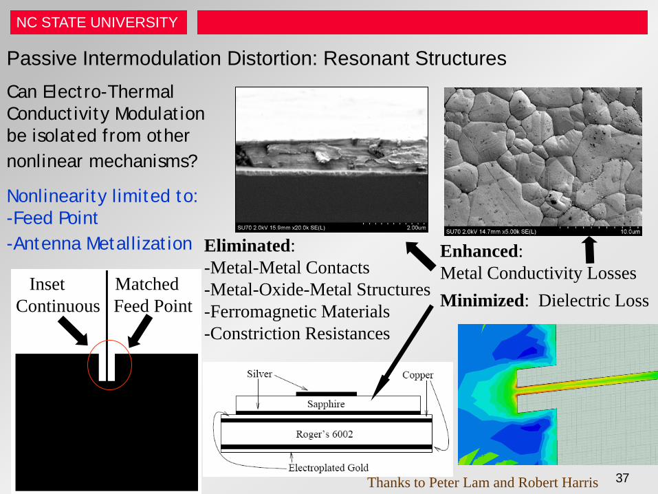
Passive Intermodulation Distortion: Resonant Structures Can Electro-Thermal Conductivity Modulation be isolated from other nonlinear mechanisms?
Inset Matched Continuous Feed Point
Eliminated: -Metal-Metal Contacts -Metal-Oxide-Metal Structures -Ferromagnetic Materials -Constriction Resistances
Enhanced: Metal Conductivity Losses Minimized: Dielectric Loss
Nonlinearity limited to: -Feed Point -Antenna Metallization
Thanks to Peter Lam and Robert Harris
NC STATE UNIVERSITY
38
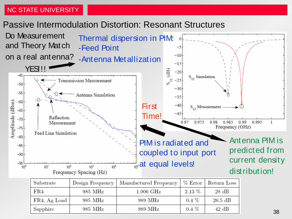
Passive Intermodulation Distortion: Resonant Structures Do Measurement and Theory Match on a real antenna?
Thermal dispersion in PIM: -Feed Point -Antenna Metallization
PIM is radiated and coupled to input port at equal levels!
YES!!!
Antenna PIM is predicted from current density distribution!
First Time!
NC STATE UNIVERSITY
Electrothermal PIM on Antennas
100
101
102
103
104
105
-95
-90
-85
-80
-75
-70
-65
-60
-55
-50
-45
Frequency Spacing (Hz)
Am
plitu
de (d
Bm
)
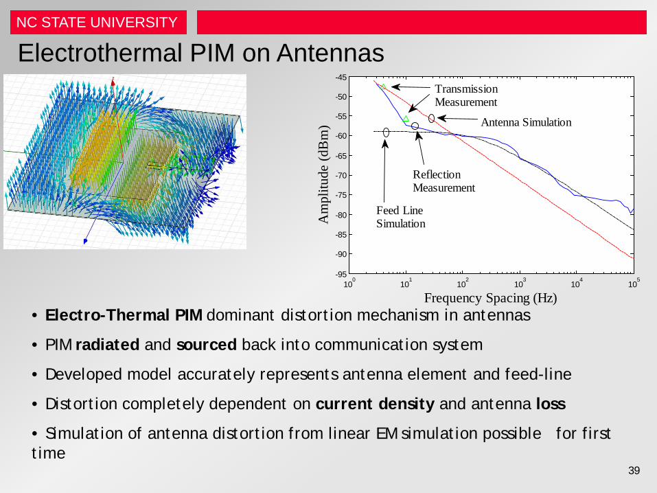
Feed LineSimulation
Antenna Simulation
ReflectionMeasurement
TransmissionMeasurement
• Electro-Thermal PIM dominant distortion mechanism in antennas
• PIM radiated and sourced back into communication system
• Developed model accurately represents antenna element and feed-line
• Distortion completely dependent on current density and antenna loss
• Simulation of antenna distortion from linear EM simulation possible for first time
39
NC STATE UNIVERSITY
NC State References • D. Winkelstein, M. B. Steer and R. Pomerleau, “Simulation of arbitrary transmission line networks with nonlinear
terminations,” IEEE Trans. on Circuits and Systems, April 1991, pp.418-422. • C. E. Christoffersen, U. A. Mughal, and M. B. Steer, “Object oriented microwave circuit simulation,” Int. J. on RF and
Microwave Computer Aided Engineering, Vol. 10, Issue 3, May/June 2000, pp. 164–182. • A. Walker, M. Steer, K. Gard, and K. M. Gharaibeh, “Multi-slice behavioral model of RF systems and devices,” IEEE Radio
and Wireless Conf. (RAWCON), Sept. 2004, pp. 71–74. • A. Walker, K.G. Gard, and M. B. Steer, ``A vector intermodulation analyzer applied to behavioral modeling of nonlinear
amplifiers with memory,” IEEE Trans. MTT, Vol. 54, Iss. 5, May 2006, pp. 1991–1999. • A. Walker, M. Steer, and K. Gard, “Simple, broadband relative phase measurement of intermodulation products,” in Proc.
65th Automatic RF Techniques Group Conf., Jun. 2005, pp. 123-127. • J. R. Wilkerson, K. G. Gard, A. G. Schuchinsky, and M. B. Steer, "Electro-thermal theory of intermodulation distortion in
lossy microwave components,” IEEE Trans. MTT, Vol. 56, Iss. 12, Part 1, December 2008, pp. 2717–2725. • G. J. Mazzaro, K.G. Gard, and M.B. Steer, “Linear amplification by time-multiplexed spectrum,” Institute of Engineering and
Technology Circuits, Devices, and Systems, Vol. 4, Iss. 5, May 2010, pp. 392–402. • G. J. Mazzaro, M. B. Steer, K. G. Gard, and A. L. Walker, “Response of RF networks to transient waveforms: interference in
frequency-hopped communications,” IEEE Trans. MTT, Vol. 56, Iss. 12, Part 1, December 2008, pp. 2808–2814. • G. J. Mazzaro, M. B. Steer, and K. G. Gard, “Intermodulation distortion in narrowband amplifier circuits,” IET Microwaves,
Antennas, & Propagation, April 2010, pp. 1149–1156. • J. M. Wetherington and M. B. Steer, “Robust non-iterative analog cancellation system for high dynamic range
measurement,” submitted to IEEE Transactions on MTT. • J. Hu, J. Q. Lowry, K. G. Gard, and M. B. Steer, “Nonlinear radio frequency model identification using a hybrid genetic
optimizer for minimal user intervention,” Institute of Engineering and Technology Microwaves, Antennas, & Propagation, In Press, 2011.
• J. R. Wilkerson, P. G. Lam, K. G. Gard, and M. B. Steer, “Distributed passive intermodulation distortion on transmission lines,” IEEE Trans. MTT, Vol. 56, No. 5, May 2011, pp. 1190–1205.
• A. Walker, M. B. Steer and K. Gard, `` Capturing asymmetry in distortion of an RF system using a multislice behavioral model,'' IEEE Microwave and Wireless Component Letters, Vol. 16, Issue 4, April 2006, pp. 212–214.
40
NC STATE UNIVERSITY
Purdue References Ferromagnetic PIM, Ultra High Dynamic Range PIM Measurements • J. Henrie, A. Christianson, W.J. Chappell, “Prediction of passive intermodulation from coaxial connectors in microwave
networks,” IEEE Transactions on Microwave Theory and Techniques, Jan 2008, pp. 209–216 • J. Henrie, A. Christianson, W.J. Chappell, “Cancellation of passive intermodulation distortion in microwave networks,”
Proc. 38th European Microwave Conference, 2008, pp. 1153–1156 • J. Henrie, A. Christianson, W.J. Chappell, “Engineered passive nonlinearities for broadband passive intermodulation
distortion mitigation,” IEEE Microwave and Wireless Components Letters, Oct 2009, pp. 614–616. Ultra High Dynamic Range PIM Measurements • A. Christianson, W.J. Chappell, “Measurement of ultra low passive intermodulation with ability to separate
current/voltage induced nonlinearities,” 2009 IEEE MTT-S International Microwave Symposium Digest, June 2009, pp. 1301–1304
• A. Christianson, J. Henrie, and W.J. Chappell, “ Higher order intermodulation product measurement of passive components,”
• IEEE Transactions on Microwave Theory and Techniques, July 2008, pp. 1729–1736 • J. Henrie, A. Christianson, W.J. Chappell, “ Linear–nonlinear interaction and passive intermodulation distortion,” • IEEE Transactions on Microwave Theory and Techniques, May 2010, pp. 1230–1237
41
NC STATE UNIVERSITY
42
Passive Intermodulation Distortion: References 1 • J. G. Simmons, “Generalized formula for the electric tunnel effect between similar electrodes separated by a thin insulating film,”
Applied Physics, vol. 34, no. 6, pp. 1793-1803, Jun. 1963. • G. C. Bailey and A. C. Ehrlich, “A study of RF nonlinearities in nickel,” Appl. Phys., vol. 50, no. 1, pp. 453-461, Jan. 1979. • A. P. Shitvov, D. E. Zelenchuk, A. G. Schuchinsky, and V. F. Fusco,“Passive intermodulation in printed lines: effects of trace
dimensions and substrate,” IET Microw. Antennas Propag., vol. 3, no. 2, pp. 260-268, Feb. 2009. • Y. Yamamoto and N. Kuga, “Short-circuit transmission line method for PIM evaluation of metallic materials,” IEEE Trans. on
Electromagnetic Compatability, vol. 49, no. 3, pp. 682-688, Aug. 2007. • A. E. Parker and J. G.Rathmell, “Broad-band characterization of FET self-heating,” IEEE Trans. on Microwave Theory and
Techniques, vol. 53, no. 7, pp. 2424-2429, Jul. 2005. • Mateu, J., “Wideband Nonlinear Response of High-Temperature Superconducting Thin Films From Transmission-Line
Measurements,” Microwave Theory and Techniques, IEEE Transactions on , vol.55, no.7, pp.1425-1430, Jul. 2007. • R. C. Joy and E. S. Schlig, “Thermal properties of very fast transistors,” IEEE Trans. Electron Devices, vol. ED-17, no. 8, pp. 586-
594, 1970. • V. Szekely and K. Tarnay, “Accurate algorithm for temperature calculation of devices in nonlinear-circuit-analysis programs,”
Electron. Lett., vol. 8, no. 19, pp. 470-472, 1972. • A. G. Kokkas, “Thermal analysis of multiple-layer structures,” IEEE Trans. Electron Devices, vol. ED-21, no. 11, pp. 674-681,
1974. • S. David, W. Batty, A. J. Panks, R. G. Johnson and C. M. Snowden, “Thermal transients in microwave active devices and their
influence on intermodulation distortion,” IEEE MTT-S Internat. Microwave Symp. Dig., vol. 1, pp. 431-434, May 2001. • R. D. Cox, “Measurement of waveguide component and joint mixing products in 6-GHz frequency diversity systems,” IEEE Trans.
Commun. Technol., vol. CT-18, no. 5, pp. 33-37, Feb. 1970. • P. L. Lui, “Passive intermodulation interference in communication systems,” Electron. Commun. Eng. J., pp. 109-118, Jun. 1990. • C. F. Hoeber, D. L. Pollard, and R. R. Nicholas, “Passive intermodulation product generation in high power communications
satellites,” presented at the AIAA 11th Commutations Satellite Systems Conf., Mar. 1986. • R. C. Chapman, J. C. Darlington, A. Savarin, R. Steinberg, A. Paul and R. Moss, “Intermodulation generation in normally passive
linear components,” Philco-Ford Corp. Rep. WDL-TR5242, Aug. 1973. • J. A. Betts and D. R. Ebenezer, “Intermodulation interference in mobile multiple communication systems at high frequencies (3-30)
MHz,”Proc. IEE, Vol. 120, no. 11, pp.1337-1344, Nov. 1973.
NC STATE UNIVERSITY
43
Passive Intermodulation Distortion: References 2 • Y. Yamamoto and N. Kuga, “Short-circuit transmission line method for PIM evaluation of metallic materials,” IEEE Trans. on
Electromagnetic Compatability, vol. 49, no. 3, pp. 682-688, Aug. 2007. • G. Macchiarella, G. B. Stracca, and L. Miglioli, “Experimental study of passive intermodulation in coaxial cavities for cellular base
stations duplexers,” in Proc. 34th European Microwave Conference, Oct. 2004, pp. 981-984. • J. Sanford, “Passive intermodulation considerations in antenna design,” in Antennas and Propagation Society International
Symposium, Jun. 1993, pp. 1651-1654. • V. Golikov, S. Hienonen, and P. Vainikainen, “Passive intermodulation distortion measurements in mobilecommunication antennas,”
in Proc. 54th Vehicular Technology Conference, Oct. 2001, pp. 2623-2625. • R. C. Joy and E. S. Schlig, “Thermal proprieties of very fast transistors,” IEEE Trans. Electron Devices, vol. ED-17, pp. 586-594,
1970. • J. S. Brodsky, R. M. Fox, and S. Veeraraghavan, “A physics-based, dynamic thermal impedance model for SOI MOSFETs,” IEEE
Trans. Electron Devices, vol. 44, pp. 957-964, May 1997. • R. M. Fox, S.-G. Lee, and D. T. Zweidinger, “The effects of BJT self-heating on circuit behavior,” IEEE J. Solid-State Circuits, vol.
28, pp. 678-685, June 1993. • R.C. Chapman, J.V. Rootsey, I. Polidi, W.W. Davidson, “Hidden Threat Multicarrier Passive Component IM Generation,” Paper 76-
296, AIAA/CASI 6th Communications Satellite Systems Conference, Montreal, Canada, April 5-8, 1976. • R. W. Keyes, “Physical problems and limits in computer logic,” IEEE Spectrum, pp. 36-45, May 1969. • G. Digele, S. Lindenkreuz, and E. Kasper, “Fully coupled dynamic electro-thermal simulation,” IEEE Trans. VLSI Syst., vol. 5, pp.
250-257, Sep. 1997. • K. J. Parsons and P. B. Kenington, “Effect of delay mismatch on a feed-forward amplifier,” IEE Proc. Circuits, Devices and
Systems, vol. 141, pp. 140-144, Apr. 1994. • J. A. Jargon, D. C. DeGroot, and K. L. Reed, “NIST passive intermodulation measurement comparison for wireless base station
equipment,” in Proc. 52nd ARFTG Comput.-Aided Design and Test for High-Speed Electron. Conf. Dig., Dec. 1998, p.128-139. • K. Y. Eng and T. E. Stern, “The order-and-type prediction problem arising from passive intermodulation interference in
communications satellites,” IEEE Trans. Comm., vol. 29, no. 5, pp. 549-555, May 1981. • H. Huan and F. Wen-bin, “On passive intermodulation at microwave frequencies,” in Proc. Asia-Pacific Conf. on Environmental
Electromagnetics, Nov. 2003, pp. 422-425.
NC STATE UNIVERSITY
44
Passive Intermodulation Distortion: References 3 • Szepessy and Zoltan, “Thermal Dynamic Model of Precision Wire-Wound Resistors,” IEEE Transactions on Instrumentation and
Measurement, vol. 51, no. 5, pp. 930-934, Oct. 2002. • Bechtold, Rudnyi, and Korvink, “Dynamic Electro-Thermal Simulation of Microsystems-a Review,” Micromechanics and
Microengineering, vol. 15, no. 11, pp. R17-R31, Oct. 2005. • I. Podlubny, Fractional Differential Equations. New York: Academic Press, 1999. • E. Rubiola and V. Giordano, “Advanced interferometric phase and amplitude noise measurements,” Review of Scientific
Instruments, vol. 73, no. 6, pp. 2445-2457, Jun. 2002. • B. Deats, R. Hartman, “Measuring passive-IM performance of RF cable assemblies,”Microwave & RF Journal, pp. 108-114, March
1997. • A. P. Shitvov, D. E. Zelenchuk, A. G. Schuchinsky, and V. F. Fusco, “Passive intermodulation generation on printed lines: Near-field
probing and observations,” IEEE Trans. on Microwave Theory and Techniques, vol. 56, no. 12, pp. 3121-3128, Dec. 2008. • W. H. Higa, “Spurious signals generated by electron tunneling on large reflector antennas,” Proc. IEEE, vol. 63, no. 2, pp. 306-313,
Feb. 1975. • W. Batty, A. J. Panks, and C. M. Snowden, “Fully coupled electro-thermal simulation of MMICs and MMIC arrays based on a
physical model,” 1999 IEEE MTT-S Int. Microwave Symp. Dig., vol. 2, pp. 693-696, June 1999.
NC STATE UNIVERSITY
45
• The dominant effect of PIM after the easy
effects are removed is Electro-thermal PIM • Thick metal reduces close-in PIM • For Transmission lines, lower impedance
lines have lower PIM.
Summary


