
NENA Functional and
Interface Standards for
Next Generation 9-1-1
Version 1.0 (i3)
NENA Functional and Interface Standards for Next Generation 9-1-1 Version 1.0 (i3)
NENA 08-002, Version 1.0, December 18, 2007
Prepared by:
National Emergency Number Association (NENA) Technical Committee Chairs
Published by NENA
Printed in USA

NENA Functional and Interface Standards for
Next Generation 9-1-1 Version 1.0 (i3)
NENA 08-002 Version 1.0, December 18, 2007
Version 1.0 December 18, 2007 Page 2 of 121
NENA
TECHNICAL STANDARD DOCUMENT
NOTICE
The National Emergency Number Association (NENA) publishes this document as a guide for the
designers and manufacturers of systems to utilize for the purpose of processing emergency calls. It is
not intended to provide complete design specifications or to assure the quality of performance of
such equipment.
NENA reserves the right to revise this NENA TECHNICAL STANDARD DOCUMENT (TSD) for
any reason including, but not limited to:
conformity with criteria or standards promulgated by various agencies
utilization of advances in the state of the technical arts
or to reflect changes in the design of equipment or services described herein.
It is possible that certain advances in technology will precede these revisions. Therefore, this NENA
TSD should not be the only source of information used. NENA recommends that readers contact
their Telecommunications Carrier representative to ensure compatibility with the 9-1-1 network.
Patents may cover the specifications, techniques, or network interface/system characteristics
disclosed herein. No license expressed or implied is hereby granted. This document shall not be
construed as a suggestion to any manufacturer to modify or change any of its products, nor does this
document represent any commitment by NENA or any affiliate thereof to purchase any product
whether or not it provides the described characteristics.
This document has been prepared solely for the use of E9-1-1 Service System Providers, network
interface and system vendors, participating telephone companies, etc.
By using this document, the user agrees that NENA will have no liability for any consequential,
incidental, special, or punitive damages arising from use of the document.
NENA‟s Technical Committee has developed this document. Recommendations for change to this
document may be submitted to:
National Emergency Number Association
4350 N Fairfax Dr, Suite 750
Arlington, VA 22203-1695
800-332-3911

NENA Functional and Interface Standards for
Next Generation 9-1-1 Version 1.0 (i3)
NENA 08-002 Version 1.0, December 18, 2007
Version 1.0 December 18, 2007 Page 3 of 121
Acknowledgments:
This document has been developed by the National Emergency Number Association (NENA)
VoIP/Packet Technical Committee Long Term Definition Working Group.
NENA recognizes the following industry experts and their companies for their contributions in
development of this document. In addition, a larger number of work group members monitored the
development of the document and commented occasionally on its contents.
Members: Company
Brian Rosen –Work Group Leader and
Technical Editor
NeuStar
Nate Wilcox – VoIP/Packet Technical
Chair
microDATA
Nadine B Abbott Telcordia
Anand Akundi Telcordia
Wayne Ballantyne Motorola
Deborah Barclay Alcatel Lucent
Marc Berryman Greater Harris County
Tom Breen AT&T
Guy Caron Bell Canada
Pierre Desjardins Positron
Brian Dupras Intrado
Marc Linsner Cisco
Roger Marshall TeleCommunication Systems, (TCS)
Patty McCalmont Intrado
Theresa Reese Telcordia
Guy Roe Mapinfo
Robert Sherry Intrado

NENA Functional and Interface Standards for
Next Generation 9-1-1 Version 1.0 (i3)
NENA 08-002 Version 1.0, December 18, 2007
Version 1.0 December 18, 2007 Page 4 of 121
TABLE OF CONTENTS
1 EXECUTIVE OVERVIEW ............................................................................................................................... 8
2 INTRODUCTION .............................................................................................................................................. 9
2.1 OPERATIONAL IMPACTS SUMMARY .................................................................................................................. 9 2.2 DOCUMENT TERMINOLOGY .............................................................................................................................. 9 2.3 REASON FOR ISSUE/REISSUE ............................................................................................................................ 9 2.4 DATE COMPLIANCE ........................................................................................................................................ 10 2.5 ANTICIPATED TIMELINE ................................................................................................................................. 10 2.6 COSTS FACTORS ............................................................................................................................................. 10 2.7 COST RECOVERY CONSIDERATIONS ............................................................................................................... 10 2.8 ACRONYMS/ABBREVIATIONS/DEFINITIONS .................................................................................................... 11 2.9 INTELLECTUAL PROPERTY RIGHTS POLICY .................................................................................................... 14
3 TECHNICAL DESCRIPTION ....................................................................................................................... 15
3.1 SCOPE ............................................................................................................................................................ 17
4 ARCHITECTURE ........................................................................................................................................... 18
4.1 SYSTEM ARCHITECTURE ................................................................................................................................ 18 4.1.1 Assumptions .............................................................................................................................................. 18 4.1.2 Functional architecture ............................................................................................................................ 20 4.1.3 Example of possible physical architecture ............................................................................................... 24 4.1.4 Example Physical Architecture................................................................................................................. 25 4.1.5 Call Architecture ...................................................................................................................................... 26
4.1.5.1 Calls and Incidents .......................................................................................................................................... 26 4.2 RELATIONSHIP OF NENA I3 TO IETF STANDARDS ......................................................................................... 28
4.2.1 Location .................................................................................................................................................... 28 4.2.1.1 Location-by-Value (LbyV) ................................................................................................................... 30 4.2.1.2 Location-by-Reference (LbyR) ............................................................................................................. 30 4.2.2 Call Signaling ........................................................................................................................................... 30 4.2.3 Distinguishing an Emergency Call ........................................................................................................... 32 4.2.4 Routing of IP-based Emergency Calls in a generic IETF SIP originating network ................................. 33 4.2.5 Generic SIP as an Emergency Services IP Network ................................................................................. 35
4.2.5.1 Simple ESInet ................................................................................................................................................. 35 4.2.5.2 Multiple ESRPs in an ESInet Architecture ..................................................................................................... 36 4.2.5.3 Hierarchical ESInet Architectures – “Network of Networks” ......................................................................... 37 4.2.5.4 Internal ESRP functions .................................................................................................................................. 38
4.2.6 End to End generic SIP emergency call architecture ............................................................................... 39 4.3 RELATIONSHIP OF NENA I3 TO IMS STANDARDS WITHIN 3GPP .................................................................... 40
4.3.1 3GPP Functional Entities ......................................................................................................................... 40 4.3.2 Additional Functional Entities in Support of an IMS-based ESInet ......................................................... 41 4.3.3 Emergency Call Routing in an IMS origination network ......................................................................... 42 4.3.4 IMS as an Emergency Services IP Network .............................................................................................. 45 4.3.5 Backup/Default Routing in an IMS-based i3 Solution Environment ........................................................ 46
4.4 RELATIONSHIP OF NENA I3 TO ATIS STANDARDS ......................................................................................... 46 4.5 LEGACY GATEWAY ARCHITECTURES -- EXAMPLES IN I3 ................................................................................ 48
4.5.1 Legacy Wireline Origination Network ...................................................................................................... 48 4.5.2 Legacy Wireless/Circuit Switched (CS) Origination Network .................................................................. 50
4.6 SERVICE ARCHITECTURE ................................................................................................................................ 51 4.6.1 Service Definitions .................................................................................................................................... 51

NENA Functional and Interface Standards for
Next Generation 9-1-1 Version 1.0 (i3)
NENA 08-002 Version 1.0, December 18, 2007
Version 1.0 December 18, 2007 Page 5 of 121
4.6.2 Service Registry ........................................................................................................................................ 53 4.6.2.1 Registration ..................................................................................................................................................... 53 4.6.2.2 Discovery ........................................................................................................................................................ 53
4.6.3 A closer look at the service architecture .................................................................................................. 54 4.6.4 Building SOA systems ............................................................................................................................... 56
4.7 SECURITY ARCHITECTURE ............................................................................................................................. 57
5 DESCRIPTION OF CALL FLOW ................................................................................................................ 58
5.1 BASIC 9-1-1 CALL ........................................................................................................................................... 58 5.1.1 Processing of incoming INVITE transaction at a Border Control Function ............................................ 61 5.1.2 Processing of an incoming INVITE transaction at a non-terminal Emergency Services Routing Proxy . 61 5.1.3 Processing of an incoming INVITE at a terminal ESRP .......................................................................... 62 5.1.4 Policy-based Routing Function routing ................................................................................................... 62 5.1.5 Processing of outgoing INVITE transactions at BCFs and non-terminal ESRPs .................................... 62 5.1.6 Abnormal Cases ........................................................................................................................................ 63
5.1.6.1 Abnormal Conditions Detected at Border Control Function ........................................................................... 63 5.1.6.2 Abnormal Conditions Detected at the ESRP ................................................................................................... 63 5.1.6.3 Abnormal Conditions Detected at the ECRF .................................................................................................. 65 5.1.6.4 Caller Abandon ............................................................................................................................................... 65
5.2 CALL FLOW IN AN IMS BASED EMERGENCY SERVICES IP NETWORK ............................................................. 66 5.3 CALL RELEASE ............................................................................................................................................... 68 5.4 RELAY CALLS ................................................................................................................................................. 68 5.5 INFORMATION FLOWS..................................................................................................................................... 68
5.5.1 Registration/Deregistration Flow Examples ............................................................................................ 69 5.5.1.1 Registration ..................................................................................................................................................... 69 5.5.1.2 Deregistration .................................................................................................................................................. 69 5.5.1.3 Registration State Subscription ....................................................................................................................... 70
5.5.2 IMS-based Call Flow Examples ............................................................................................................... 70 5.5.2.1 Emergency Call Routing in an IMS-based Originating Network .................................................................... 70 5.5.2.2 Emergency Call Routing in an IMS Emergency Services IP Network ............................................................ 71 5.5.2.3 PSTN Call Origination presented to an IMS based Emergency Services IP Network .................................... 76 5.5.2.4 PSAP Busy – IMS specific example ............................................................................................................... 77 5.5.2.5 Emergency Call Routing in an IMS-based Originating Network .................................................................... 78 5.5.2.6 Emergency Call Routing in an IMS Emergency Services IP Network ............................................................ 79 5.5.2.7 PSTN Call Origination presented to an IMS based Emergency Services IP Network .................................... 84 5.5.2.8 PSAP Busy – IMS specific example ............................................................................................................... 85 5.5.2.9 PSAP Unavailable for Service - IMS specific example ................................................................................... 87
5.6 BRIDGING ANOTHER PSAP ............................................................................................................................ 88 5.7 3RD PARTY ORIGINATION ................................................................................................................................ 89 5.8 OVERLOAD (FORMERLY CONGESTION CONTROL) .......................................................................................... 90
5.8.1 PSAP Overload ......................................................................................................................................... 91 5.8.2 PSAP Overload Policy ............................................................................................................................. 91 5.8.3 Element Overload ..................................................................................................................................... 92 5.8.4 Collecting and Disseminating Data from Diverted Callers ...................................................................... 93
6 SERVICE CREATION .................................................................................................................................... 93
6.1 DEFINING A NEW SERVICE .............................................................................................................................. 93 6.2 SERVICE REGISTRATION AND DISCOVERY ...................................................................................................... 94
6.2.1 Service Registration .................................................................................................................................. 94 6.2.2 Service Discovery ..................................................................................................................................... 95
6.3 INTERACTING WITH SERVICES ......................................................................................................................... 95 6.4 SERVICE TERMINATION .................................................................................................................................. 95
7 BASIC SERVICES ........................................................................................................................................... 96

NENA Functional and Interface Standards for
Next Generation 9-1-1 Version 1.0 (i3)
NENA 08-002 Version 1.0, December 18, 2007
Version 1.0 December 18, 2007 Page 6 of 121
7.1 SERVICE TYPES .............................................................................................................................................. 96 7.2 DATA ASSOCIATED WITH A CALL .................................................................................................................... 96 7.3 DATA ASSOCIATED WITH A LOCATION ............................................................................................................ 96 7.4 DATA ASSOCIATED WITH A CALLER ................................................................................................................ 96 7.5 DATA ASSOCIATED WITH A PSAP ................................................................................................................... 97 7.6 INTRA-EMERGENCY SERVICES IP NETWORK ROUTING .................................................................................. 97 7.7 LOGGING ........................................................................................................................................................ 97
8 EVENT NOTIFICATION ............................................................................................................................... 98
8.1 MATCHING CONSUMERS WITH PRODUCERS .................................................................................................... 99 8.2 EVENT TOPICS REGISTRY ............................................................................................................................. 100 8.3 PUBLISHER REGISTRY .................................................................................................................................. 100 8.4 EVENT NOTIFICATION MESSAGES................................................................................................................. 101 8.5 ADVANCED EVENT NOTIFICATION MECHANISMS.......................................................................................... 101 8.6 USE CASE FOR LOCATION-SENSITIVE EVENTS ............................................................................................... 101
9 SECURITY ..................................................................................................................................................... 102
9.1 AUTHENTICATION ........................................................................................................................................ 103 9.1.1 Authentication methods .......................................................................................................................... 103 9.1.2 SAML ...................................................................................................................................................... 103 9.1.3 Credentials ............................................................................................................................................. 103 9.1.4 Certificate Policies ................................................................................................................................. 103 9.1.5 Certificate Revocation Lists .................................................................................................................... 104 9.1.6 Authentication using TLS ....................................................................................................................... 104 9.1.7 Authentication using Web Services ......................................................................................................... 104 9.1.8 Authentication using SIP ........................................................................................................................ 104
9.2 AUTHORIZATION .......................................................................................................................................... 104 9.3 INTEGRITY PROTECTION OF MESSAGES ......................................................................................................... 105 9.4 PRIVACY ...................................................................................................................................................... 105 9.5 NON-REPUDIATION ...................................................................................................................................... 105
10 SERVICE MANAGEMENT ......................................................................................................................... 105
10.1 PROVISIONING .............................................................................................................................................. 105 10.2 REMOTE TELECOMMUNICATOR MANAGEMENT ............................................................................................ 105 10.3 ROUTING MANAGEMENT .............................................................................................................................. 106 10.4 ALARMS ....................................................................................................................................................... 106 10.5 REPORTS ...................................................................................................................................................... 107
10.5.1 Logging .............................................................................................................................................. 107 10.5.2 Quality Metrics .................................................................................................................................. 107
10.5.2.1 VoIP quality metrics ..................................................................................................................................... 108
11 ROLES AND RESPONSIBILITIES ............................................................................................................ 108
11.1 AGENCIES ..................................................................................................................................................... 108 11.2 FUNCTIONAL ELEMENT RESPONSIBLE AGENCY............................................................................................ 109 11.3 SUMMARY OF AGENCIES AND OTHER ENTITIES RESPONSIBILITIES ............................................................... 110
11.3.1 Access Network Operator .................................................................................................................. 110 11.3.2 Calling Network Operator ................................................................................................................. 110 11.3.3 Regional Emergency Communications Agency ................................................................................. 111 11.3.4 State Emergency Communications Agency ........................................................................................ 111 11.3.5 9-1-1 Authority .................................................................................................................................. 112 11.3.6 PSAP .................................................................................................................................................. 112

NENA Functional and Interface Standards for
Next Generation 9-1-1 Version 1.0 (i3)
NENA 08-002 Version 1.0, December 18, 2007
Version 1.0 December 18, 2007 Page 7 of 121
12 PROFILES AND THE MINIMAL PROFILE DEFINITION ................................................................... 112
13 REFERENCES ............................................................................................................................................... 115

NENA Functional and Interface Standards for
Next Generation 9-1-1 Version 1.0 (i3)
NENA 08-002 Version 1.0, December 18, 2007
Version 1.0 December 18, 2007 Page 8 of 121
1 Executive Overview
Major changes in the existing emergency services architecture are being driven by the rapid
evolution of the types of devices and services that can be used to call for help. Also there is an
increasing volume and diversity of information that can be made available to assist PSAPs and
responders in an emergency. NENA recognizes this is a fundamental update to the North American
9-1-1 system, and is addressing the challenge with a system design called “Next Generation 9-1-1”
(NG9-1-1). NG9-1-1 is the evolution of Enhanced 9-1-1 to an all-IP-based emergency
communications system. This technical specification, commonly referred to as i3, is the first version
of the NG9-1-1 system design.
NENA i3 introduces the concept of an Emergency Services IP network (ESInet), which is designed
as an IP-based inter-network (network of networks) shared by all agencies which may be involved in
any emergency. The i3 Public Safety Answering Point (PSAP) is capable of receiving IP-based
signaling and media for delivery of emergency calls conformant to the i3 standard.
This edition of the i3 standard specifies that all calls enter the ESInet using Session Initiation
Protocol (SIP) signaling. The PSAP is selected using the Emergency Call Routing Function (ECRF),
and calls are delivered to the PSAP with location and callback information. It further specifies that a
Location Validation Function (LVF) must be applied by the origination network to validate location
prior to the origination of 9-1-1 calls.
The i3 document references several types of originating networks that could be used to deliver calls
to an ESInet, including legacy circuit-switched networks (wireline or wireless). Those must undergo
mediation via a gateway to convert the incoming signaling to SIP. In addition, functionality must be
applied to legacy emergency calls to acquire location and use the information obtained in call setup
signaling to route a call to the PSAP. These originating networks are shown for reference only and
are explicitly out of scope for this document.
NG9-1-1 encourages the creation of many new coordination and information access services to
enrich collaborative interactions between all agencies involved in processing emergency service
requests. A Service-Oriented Architecture (SOA) approach has been selected to facilitate the
development of those.
This document describes the relationship between NENA standards and standards from other
Standards Development Organizations (SDOs) such as the IETF and 3GPP/3GPP2. The application
of IMS architecture concepts may appear in the originating network/domain, and as an instance of an
IMS-based ESInet. A generic SIP and an IMS-based ESInet are described in this version.
This document is issued as the NENA recommended standard for functions and interfaces between
elements within an ESInet. It provides a Stage 2 definition to include 1) interactions between
origination networks and the ESInet, 2) functional requirements and their interactions within an
ESInet and 3) call delivery to a public safety agency such as a PSAP. The present document also
illustrates an example of an i3 physical architecture to provide context for the functional interactions.

NENA Functional and Interface Standards for
Next Generation 9-1-1 Version 1.0 (i3)
NENA 08-002 Version 1.0, December 18, 2007
Version 1.0 December 18, 2007 Page 9 of 121
2 Introduction
2.1 Operational Impacts Summary
The i3 specification encompasses a complete redesign of the entire 9-1-1 system, affecting all
elements, protocols, processes and procedures. It will have far reaching impacts on all participants in
the 9-1-1 system.
This document reflects the long-term view that the networks that connect the PSAP to callers and to
other PSAPs and responders will evolve to be IP-based.
Location of the caller (or a reference to it) will be conveyed with the call, so that routing can be
accomplished dynamically along the path of the call from the caller to the call taker, and so that
location is available as soon as the call is answered.
Location within the 9-1-1 system will be regularized, and made conformant with other users of
location (for example, URISA standards). All elements will support both civic and geodetic forms
of location.
Selective Routers will not be used when the network completes its evolution to i3; IP-based calls
will be delivered directly to the PSAP and calls from other technologies will have gateways between
their networks and the IP-based ESInet.
Emergency Services Zones (ESZ) and corresponding Emergency Services Numbers (ESN) as
currently known will be eliminated. Routing to any number of response agencies based on the
location of the caller will be supported.
2.2 Document Terminology
The terms "shall", "must" and "required" are used throughout this document to indicate required
parameters and to differentiate from those parameters that are recommendations. Recommendations
are identified by the words "desirable" or "preferably".
2.3 Reason for Issue/Reissue
This document is issued to define a specification describing the functionality supported by elements
within an IP-based ESInet and the interconnection of these functional elements. This version (Issue
1.0) of the Functional and Interface Standards for Next Generation 9-1-1 (i3) is intended to be used
in SDO liaisons, and Request for Information (RFI)-like processes. The NENA LTD Working Group
plans to release subsequent versions of the Standard as new work items are identified and resolved.
NENA reserves the right to modify this document. Upon revision, the reason(s) will be provided in
the table below.
Version Date Reason For Changes
Original 12/18/2007 Initial Document
NENA Functional and Interface Standards for
Next Generation 9-1-1 Version 1.0 (i3)
NENA 08-002 Version 1.0, December 18, 2007
Version 1.0 December 18, 2007 Page 10 of 121
2.4 Date Compliance
All systems that are associated with the 9-1-1 process shall be designed and engineered to ensure that
no detrimental, or other noticeable impact of any kind, will occur as a result of a date/time change up
to 30 years subsequent to the manufacture of the system. This shall include embedded application,
computer based or any other type application.
To ensure true compliance, the manufacturer shall upon request, provide verifiable test results to an
industry acceptable test plan such as Telcordia GR-2945 or equivalent.
2.5 Anticipated Timeline
As this is a major change to the 9-1-1 system, adoption of this standard will take several years.
Experience with the immediately prior major change to 9-1-1 (i.e., Phase II wireless) suggests that
unless consensus among government agencies at the local, state and federal levels, as well as
carriers, vendors and other service providers is reached, implementation for the majority of PSAPs
could take a decade. The Long Term Definition (LTD) working group chose technology
commensurate with a 2-5 year implementation schedule.
2.6 Costs Factors
This is an all-new 9-1-1 system; the cost of everything will change. At this time it is difficult to
predict the costs of the system and more work will be needed by vendors and service providers to
determine the impact of the changes on their products and operations. One viewpoint within the
LTD working group was that the cost of the new system will be significantly less than the cost of the
existing system, although in the transition from the existing system to the new one, duplicate
elements and services will have to be maintained at a higher overall cost. Another viewpoint was
that costs may not be reduced, but the improved service to the public justifies these costs. The
charge to the LTD working group was to NOT consider cost in making technical decisions.
Nevertheless, due to the pragmatic experience of the participants, the document tended to consider
cost as one of the variables in making choices. Estimating the cost to deploy the entire NG9-1-1
system is the purview of other groups within NENA.
2.7 Cost Recovery Considerations
Traditionally, much of the cost of the existing E9-1-1 Service Provider infrastructure has been
supported through the collection of fees and surcharges on wireline and wireless telephone service.
Changes in the telecommunications industry has caused the basis on which the fees and surcharges
are collected to be rendered obsolete, and the architecture described in this document further sunders
the assumptions on which the current revenue streams are based. This document does not make
recommendations on how funding should be changed, but believes a change from the traditional
mechanisms is required.

NENA Functional and Interface Standards for
Next Generation 9-1-1 Version 1.0 (i3)
NENA 08-002 Version 1.0, December 18, 2007
Version 1.0 December 18, 2007 Page 11 of 121
2.8 Acronyms/Abbreviations/Definitions
This is not a glossary. See NENA 00-002 - NENA Master Glossary of 9-1-1 Terminology located on
the NENA web site for a complete listing of terms used in NENA documents.
The following Acronyms are used in this document:
Acronym Description
3GPP 3RD
Generation Partner Project
3GPP2 3rd
Generation Partnership Project 2
AAA Authorization, Admission and Accounting
AES Advanced Encryption Standard
AIP Access Infrastructure Provider
ANI Automatic Number Identification
ANS American National Standard
ANSI American National Standards Institute
AoR Address of Record
APCO Association of Public Safety Communications Officials
ATIS Alliance for Telecommunications Industry Solutions
ATIS-ESIF Alliance for Telecommunications Industry Solutions – Emergency Services
Interconnection Forum
B2BUA Back to Back User Agent
BCF Border Control Function
CAD Computer Aided Dispatch
CAMA Centralized Automatic Message Accounting
CAP Common Alerting Protocol
CPE Customer Premises Equipment
CRL Certificate Revocation List
CS Circuit Switched
CSCF Call Session Control Function
CSP Communication Service Provider
DHCP Dynamic Host Control Protocol (i2) Dynamic Host Configuration Protocol
DNS Domain Name Server (or Service or System)
DoS Denial of Service
DSL Digital Subscriber Line
E9-1-1 Enhanced 9-1-1
ECRF Emergency Call Routing Function
ecrit Emergency Context Resolution In the Internet
E-CSCF Emergency Call Session Control Function
EISI Emergency Information Services Interface
EPAD Emergency Provider Access Directory
ESNI Emergency Services Network Interfaces

NENA Functional and Interface Standards for
Next Generation 9-1-1 Version 1.0 (i3)
NENA 08-002 Version 1.0, December 18, 2007
Version 1.0 December 18, 2007 Page 12 of 121
The following Acronyms are used in this document:
ESIF Emergency Services Interconnection Forum
ESInet Emergency Services IP Network
ESMI Emergency Services Messaging Interface
ESN Emergency Service Number, Electronic Serial Number, Emergency Service
Network
ESNet Emergency Services Network
ESQK Emergency Services Query Key
ESRK Emergency Services Routing Key
ESRP Emergency Services Routing Proxy
ESZ Emergency Services Zone (Same as ESN)
FCC Federal Communications Commission
geopriv Geolocation and Privacy
GSM Global Standard for Mobile Communication
GUID Globally Unique Identifier
HSS Home Subscriber Server
IETF Internet Engineering Task Force
IM Instant Messaging
IMS IP Multimedia Subsystem
IP Internet Protocol
IP-CAN IP Connectivity Access Network
IP-PBX Internet Protocol Private Branch Exchange
IPSec Internet Protocol Security
ISDN Integrated Services Digital Network
ISP Internet Service Provider
LAN Local Area Network
LDAP Lightweight Directory Access Protocol
LIS Location Information Server
LO Location Object
LoST Location to Service Translation
LRF Location Retrieval Function
LTD Long Term Definition
LVF Location Validation Function
MEP Message Exchange Pattern
MPC/GMLC Mobile Positioning Center/ Gateway Mobile Location Center
MSC Mobile Switching Center
MF Multi-Frequency
MPLS Multi-Protocol Label Switching
MSAG Master Street Address Guide
MSC Mobile Switching Center
NCIC National Crime Information Center, National Crime Enforcement Center
NENA National Emergency Number Association

NENA Functional and Interface Standards for
Next Generation 9-1-1 Version 1.0 (i3)
NENA 08-002 Version 1.0, December 18, 2007
Version 1.0 December 18, 2007 Page 13 of 121
The following Acronyms are used in this document:
NG9-1-1 Next Generation 9-1-1
NGES Next Generation Emergency Services
NGN Next Generation Network
OASIS Organization for the Advancement of Structured Information Standards
P-CSCF Proxy Call Session Control Function
PCA PSAP Credentialing Agency
PDA Personal Digital Assistant
PIDF Presence Information Data Format
PIDF-LO Presence Information Data Format – Location Objects
PKI Public Key Infrastructure
PRF Policy Routing Function
PSAP Public Safety Answering Point or Primary Public Safety Answering Point
PSTN Public Switched Telephone Network
PTSC Packet Technologies and Services Committee
QoS Quality of Service
RBAC Role Based Access Control profile
RDF Routing Determination Function
REST Representational State Transfer
RG Response Gateway, Routing Gateway
RTCP Real Time Control Protocol
RTP Real Time Transport Protocol
RTSP Real Time Streaming Protocol
S-CSCF Serving Call Session Control Function
SAML Security Assertion Markup Language
SBC Session Border Control
SDO Standards Development Organization
SDP Session Description Protocol
SHA Secure Hash Algorithm
SIP Session Initiation Protocol
SMS Short Message Service
SOA Service Oriented Architecture
SOAP Simple Object Access Protocol
SPML Service Provisioning Markup Language
SR Selective Routing, Selective Router [a.k.a., E9-1-1 Tandem, or Enhanced 9-1-1
(E9-1-1) Control Office]
SS7 Signaling System 7
TCP Transport/Transmission Control Protocol
TDM Time Division Multiplexing
TLS Transport Layer Security
TN Telephone Number
TOPS Technology and Operations Council
NENA Functional and Interface Standards for
Next Generation 9-1-1 Version 1.0 (i3)
NENA 08-002 Version 1.0, December 18, 2007
Version 1.0 December 18, 2007 Page 14 of 121
The following Acronyms are used in this document:
TRD Technical Requirements Document
TTY Teletypewriter (a.k.a. TDD, Telecommunications Device for the Deaf and Hard-
of-Hearing)
UA User Agent
UAC User Agent Client
UAS User Agent Service
UDDI Universal Description, Discovery and Integration
UDP User Datagram Protocol
UE User Element
URI Uniform Resource Identifier
URISA Urban and Regional Information Systems Association
URN Uniform Resource Name
USPS United States Postal Service
UTC Universal Coordinated Time
VF Validation Function
VPN Virtual Private Network
VoIP Voice over Internet Protocol
WSDL Web Service Definition Language
WSS Web Services Security
WTSC Wireless Technologies and Systems Committee
XACML eXtensible Access Control Markup Language
XML eXtensible Markup Language
XSD W3C XML Schema Definition
2.9 Intellectual Property Rights Policy
NENA takes no position regarding the validity or scope of any Intellectual Property Rights or other
rights that might be claimed to pertain to the implementation or use of the technology described in
this document or the extent to which any license under such rights might or might not be available;
nor does it represent that it has made any independent effort to identify any such rights.
NENA invites any interested party to bring to its attention any copyrights, patents or patent
applications, or other proprietary rights that may cover technology that may be required to implement
this standard.
Please address the information to:
National Emergency Number Association
4350 N Fairfax Dr, Suite 750
Arlington, VA 22203-1695
800-332-3911

NENA Functional and Interface Standards for
Next Generation 9-1-1 Version 1.0 (i3)
NENA 08-002 Version 1.0, December 18, 2007
Version 1.0 December 18, 2007 Page 15 of 121
3 Technical Description
After more than 30 years of service, the basic architecture of the North American 9-1-1 system is not
capable of meeting the needs of the next generation communication for the communities that it
serves. Rapid evolution of the types of devices and services that can be used to call for help, plus
increasing volume and diversity of information that can be made available to assist PSAPs and
responders in an emergency require major changes in the architecture. NENA recognizes this is a
fundamental change to the North American 9-1-1 system, and is addressing the challenge with a
system design called NG9-1-1. It is expected to be the evolution of Enhanced 9-1-1 to an all-IP
based emergency communications system. This specification, commonly referred to as i3, is the first
version of the NG9-1-1 system design.
In the evolved network, calls1 originate from many different kinds of devices and services. If a
consumer in need of emergency assistance has a reasonable expectation that a call for help should
work on a device or service, NG9-1-1 is designed to make it possible for that device or service to get
help. SMS, IM, Video phones, PDAs, telematics, and similar technologies are today reasonable
sources of emergency calls.
NENA‟s i3 introduces the concept of an ESInet, which is envisioned as an IP-based inter-network
(network of networks) shared by all agencies which may be involved in any emergency. A local
ESInet, which may typically be county wide, will be interconnected to neighboring county‟s ESInet
for mutual aid purposes. Because ESInets are IP-based, such interconnections will allow any agency
to communicate with any other agency or service on any of the interconnected ESInets. The i3 PSAP
is a PSAP that is capable of receiving IP-based signaling and media for delivery of emergency calls
and for originating calls conformant to the i3 standards. The i3 PSAPs are inherently multimedia.
Within the i3 standard, location information may be carried directly (the actual location) or indirectly
(a reference to location that can be exchanged by a LIS for the actual location). The standard allows
either civic (street address) or geodetic (latitude/longitude/altitude) forms of location to be used.
This document defines location determination as the set of functions to accurately and automatically
determine the position of the IP endpoint device and associate that location information uniquely
with that device. Location acquisition refers to the functions necessary to make that location
information available to the device on request, or to make that location information available to a
Proxy acting on behalf of that device so that location information can be used for emergency calling.
The ECRF converts location information (either civic address or geo-coordinates) to provide a URI
that can be used to route an emergency call toward the appropriate PSAP for the caller‟s location.
The PRF applies techniques to determine alternate routing addresses based on policy information
associated with the destination PSAP.
1 A request for help by someone in need of help, or acting on behalf of someone who needs help is a
“call” in i3. This covers the normal case of a telephone call, but also includes a two-way video call,
an interactive text (TTY or newer forms of TTY), an SMS, an Instant Message or some new
mechanisms for communications in the future

NENA Functional and Interface Standards for
Next Generation 9-1-1 Version 1.0 (i3)
NENA 08-002 Version 1.0, December 18, 2007
Version 1.0 December 18, 2007 Page 16 of 121
Calls from legacy networks (wireline or wireless) which are not inherently IP-based must undergo
signaling interworking (i.e., at a gateway system) to convert the incoming MF or SS7 signaling to the
SIP. In addition, functionality must be applied to legacy emergency calls that will allow the
information provided in call setup signaling by the wireline switch or MSC (e.g., calling
number/ANI, ESRK, cell site/sector) to be used to route a call and provide location to the PSAP.
Determination of call routing for legacy calls will actually involve two functions; a location
acquisition function and a call routing function. The location acquisition function will be
responsible for translating the information received with a legacy emergency call into location
information that could be used as input to the call routing function (i.e., a civic address or geo-
location).
NENA i3 specifies that emergency calls will be initially conveyed within the ESInet using SIP
signaling. As such, protocol mediation may be required “at the edge”.
NG9-1-1 encourages the creation of many new coordination and information access services. These
will enrich collaborative interactions between all agencies involved in processing emergency service
requests. Characterized as “service-orientated”, this approach to NG9-1-1 will rely heavily on
eXtensible Markup Language (XML) technology.
This document describes the relationship between NENA standards and standards from other
standards organizations. It describes how IETF standards are used in the signaling and routing of
emergency calls within the ESInet(s). It also describes the relationship between NENA standards
and 3GPP IMS standards IMS architecture concepts may be used in an originating network/domain.
IMS architecture concepts may also be used to implement an ESInet.
This document is issued as the NENA recommended standard for functions and interfaces between
elements in an ESInet. It provides a Stage 2 definition to include interactions between origination
networks and the ESInet, functional requirements and their interactions within an ESInet and call
delivery to a public safety agency such as a Public Safety Answering Point (PSAP). The equivalent
of an ANSI “Stage 1” document is TRD 08-751, NENA i3 Technical Requirements Document [1].
The present document also illustrates an example of an i3 physical architecture to provide context for
the functional interactions.
While this document does include specifications for the methods used to route and deliver calls
within the ESInet, it does not include specifications for how calls are routed and presented to the
ESInet. The Stage 3 definition is expected to be provided by specific Standard Development
Organizations such as IETF, ATIS, and 3GPP/3GPP2, etc. This document only describes the
interface between an origination network (or the Internet) and the ESInet, as well as the interfaces
and functional elements within the ESInet. It does describe, for illustration purposes, how IP and
legacy origination networks might process 9-1-1 calls. It does specify a Location Validation
Function (LVF) which must be used by the origination network to validate location prior to a 9-1-1
call, and mandates the use of the ECRF to route calls to the ESInet. This document does not
standardize functions internal to an i3 PSAP, nor does it constrain the implementation of any
functional element.
Use of this document will:
NENA Functional and Interface Standards for
Next Generation 9-1-1 Version 1.0 (i3)
NENA 08-002 Version 1.0, December 18, 2007
Version 1.0 December 18, 2007 Page 17 of 121
Provide guidance to Standards Development Organizations (SDO) in defining Stage 3 standards;
Specify an architecture to aid equipment and service providers in implementing solutions that are
interoperable by conforming to these recommendations;
Define new capabilities for persons seeking help, and for the PSAPs and responders that can
render assistance;
Allow PSAPs to accept calls from a wider variety of devices and services;
Improve the quality and range of services provided to all callers;
Specify an architecture that will react better than existing systems in major disasters;
Specify an architecture that will react better to deliberate attacks on the system.
3.1 Scope
The i3 solution encompasses the definition of:
The architecture of the emergency calling system;
External interfaces between PSAPs and public/private networks delivering 9-1-1 calls to the
ESInet;
External interfaces to systems and databases not in the PSAP that supply data and assistance
in processing a call;
External interfaces to systems that handle a call past the point where a call taker has
exclusive control over it, such as the handoff to the Computer Aided Dispatch system;
External interfaces to upper level management systems, such as disaster management
systems, as well as peer PSAPs;
Functions such as location-based routing, data creation and maintenance.
Explicitly out of scope are:
Intra PSAP interfaces;
Responder systems (e.g. Computer Aided Dispatch (CAD) systems, although the external
interface to the CAD system is in scope);
Transition from legacy E9-1-1 to NG9-1-1 infrastructure;
Push-to-Talk services.
This document references other work for:
Location determination, acquisition, conveyance and update;
Emergency call origination;
Routing of emergency calls prior to entry to the ESInet.
NENA Functional and Interface Standards for
Next Generation 9-1-1 Version 1.0 (i3)
NENA 08-002 Version 1.0, December 18, 2007
Version 1.0 December 18, 2007 Page 18 of 121
There may be multiple architectures for the realization of the ESInet. This document provides
specific content on both a “generic” SIP-based solution2, as well as an IMS-based solution as
examples. Future editions may provide more detail on other architectures.
4 Architecture
NENA i3 introduces the concept of an ESInet which is envisioned as an IP-based inter-network
(network of networks) shared by all agencies which may be involved in any emergency. A local
ESInet, which typically would be county-wide, will be interconnected to a neighboring county‟s
ESInet for mutual aid purposes. Because ESInets are IP-based, such interconnections will allow any
agency to communicate with any other agency or service on any of the interconnected ESInets.
Indeed, if every local ESInet is interconnected with its neighbors, any agency anywhere in the
country can connect with any other agency, if authorized. This characteristic of routed IP networks
creates a national ESInet out of interconnected local ESInets.
ESInets connect dispersed, possibly redundant elements with standardized interfaces. PSAPs are
seen as elements within the ESInet, both using as well as providing services on it. The network
provides connectivity for call signaling, media and service discovery, invocation and management.
The architecture envisions that all calls will be answered by i3 PSAPs as IP (e.g. SIP) via gateways
connecting non IP-based callers. The i3 PSAPs are inherently multimedia, accepting voice, video
and text calls for help.
4.1 System Architecture
4.1.1 Assumptions
As defined within the scope statement above, the i3 system architecture covers the ESInet and the
location-to-URI mapping mechanism which is used to deliver (i.e., route) a call to the appropriate
PSAP.
It is assumed within this document, that a complete end-to-end network is broken up into two parts–
the “Origination Network” and the “Emergency Services IP Network”. In addition, the PSAP will
have a network internal to it.
Emergency call origination is beyond the scope of this i3 specification, however in an effort to
provide a complete context for understanding an end-to-end call, a few examples of originating
networks, their functional elements, and interfaces are described. The scope of i3 does, however,
include call routing and location validation functions which are used by the origination network.
Origination networks can be built using a generic SIP architecture, or an IMS-based SIP architecture.
Specific examples provided within this document for IP network origination include:
2 Here, a “generic SIP” means an RFC3261-compliant origination system with little additional
functionality. Such networks are common in non-IMS implementations of Voice over IP. Generic
SIP systems have User Agents, Registrars, and incoming and outgoing Proxy Servers.

NENA Functional and Interface Standards for
Next Generation 9-1-1 Version 1.0 (i3)
NENA 08-002 Version 1.0, December 18, 2007
Version 1.0 December 18, 2007 Page 19 of 121
1. A generic SIP-based edge routing model;
2. A generic SIP-based proxy routing model;
3. An IMS Emergency Service call routing model (3GPP reference architecture).
A local ESInet can serve one or more PSAPs. ESInets can be interconnected with IP routers, as any
IP network can be, to form a “network of networks”. Such interconnections can form regional,
statewide or even nationwide ESInets.
Any constituent ESInet can be based on a generic SIP architecture or alternatively, based on an IMS
architecture. Several examples are provided. This NENA standard considers both approaches and
avoids a single recommendation for one choice over the other.
No carrier3 is assumed in the i3 Solution architecture. Calls will be presented by a much wider set of
call processors ranging from enterprises, to non-traditional service providers, and even to
individuals. As with email, IP-based telecommunications does not depend on carriers, although we
expect most calls to come from carriers.
Calls may originate from many different kinds of devices and services. If a consumer in need of
emergency assistance has a reasonable expectation that a call for help should work on a device or
service, NG9-1-1 is designed to make it possible for that device or service to contact help. We
consider SMS, IM, video phones, PDAs, telematics and whatever comes next to be reasonable
sources of emergency calls.
Calls will be multimedia. Audio, video and text are all acceptable media to i3 PSAPs.
Telecommunications is now global. International roaming is now permitted for wireless and VoIP as
well as other services. The standards for emergency calling must be internationalized (as is the
Internet where there are no national variations of any Internet protocol).
While the scope of this document does NOT include migration from existing 9-1-1 Emergency
networks to i3 ESInets, we consider legacy wireline and wireless origination networks to be in scope
since we believe such networks will persist beyond the transition period.
3 In the context of this document, the term “carrier” refers to a function provided by a business entity
to a customer base, typically for a fee. Examples of carriers and associated services are: PSTN
service by a Local Exchange Carrier, VoIP service by a VoIP Service Provider, email service
provided by an Internet Service Provider.
NENA Functional and Interface Standards for
Next Generation 9-1-1 Version 1.0 (i3)
NENA 08-002 Version 1.0, December 18, 2007
Version 1.0 December 18, 2007 Page 20 of 121
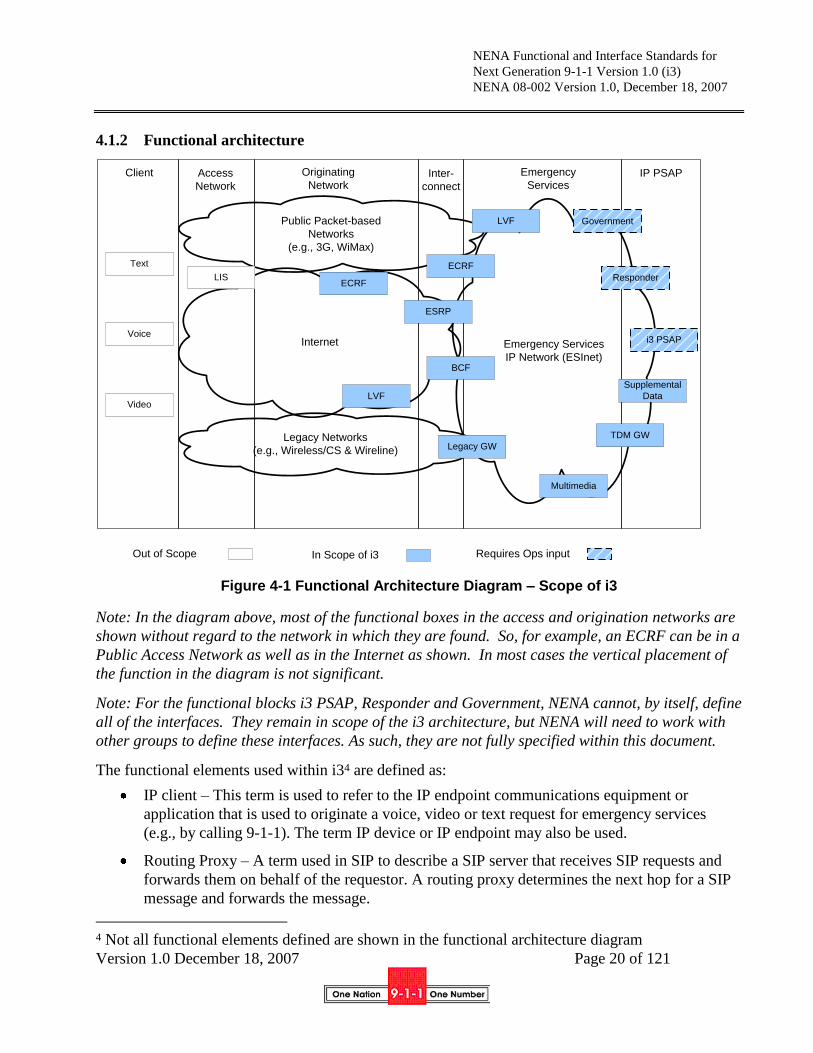
4.1.2 Functional architecture
Figure 4-1 Functional Architecture Diagram – Scope of i3
Note: In the diagram above, most of the functional boxes in the access and origination networks are
shown without regard to the network in which they are found. So, for example, an ECRF can be in a
Public Access Network as well as in the Internet as shown. In most cases the vertical placement of
the function in the diagram is not significant.
Note: For the functional blocks i3 PSAP, Responder and Government, NENA cannot, by itself, define
all of the interfaces. They remain in scope of the i3 architecture, but NENA will need to work with
other groups to define these interfaces. As such, they are not fully specified within this document.
The functional elements used within i34 are defined as:
IP client – This term is used to refer to the IP endpoint communications equipment or
application that is used to originate a voice, video or text request for emergency services
(e.g., by calling 9-1-1). The term IP device or IP endpoint may also be used.
Routing Proxy – A term used in SIP to describe a SIP server that receives SIP requests and
forwards them on behalf of the requestor. A routing proxy determines the next hop for a SIP
message and forwards the message.
4 Not all functional elements defined are shown in the functional architecture diagram
Emergency Services
IP Network (ESInet)
Internet
IP PSAPInter-
connect
Legacy Networks
(e.g., Wireless/CS & Wireline)
Responder
Government
Multimedia
Supplemental
Data
Voice
Video
Client
Out of Scope
Access
Network
Originating
Network
Public Packet-based
Networks
(e.g., 3G, WiMax)
Emergency
Services
i3 PSAP
TDM GW
Legacy GW
Text
ECRF
ESRP
BCF
LVF
ECRF
LVF
LIS
Requires Ops inputIn Scope of i3

NENA Functional and Interface Standards for
Next Generation 9-1-1 Version 1.0 (i3)
NENA 08-002 Version 1.0, December 18, 2007
Version 1.0 December 18, 2007 Page 21 of 121
User Agent (UA) – Terminology used in the context of SIP to identify the IP device. In SIP, a
UA is a network element that is capable of generating SIP requests (e.g., INVITE) and is
capable of generating responses for received requests.
Back to Back User Agent (B2BUA) – This is a logical entity that receives a request and
processes it as a user agent server (UAS). In order to determine how the request should be
answered, it acts as a user agent client (UAC) and generates requests. Unlike a proxy server
it maintains dialog state and must participate in all requests sent on the dialogs it established.
Legacy PSAP – This term is used to describe PSAPs that are not capable of communicating
with VoIP protocols or of supporting the i3-based interfaces specified as part of the i3
solution.
Legacy Gateway – This term is used to refer to a signaling and media interconnection point
between callers in legacy wireline/wireless originating networks and the i3 architecture, so
that i3 PSAPs are able to receive emergency calls from such legacy networks.
TDM Gateway – While NENA can specify the behavior of i3 PSAPs, it cannot specify
responder systems. A gateway may be needed to connect an i3 PSAP to a responder who
retains a TDM interface.
Domain Name Server (DNS) – The DNS is used in the Internet today to resolve domain
names. The input to a DNS is a domain name (e.g., telcordia.com); the response is the IP
address of the domain. The DNS allows people to use easy to remember text-based addresses
and the DNS translates those names into routable IP addresses.
Web Services – Web Services identifies an industry standard protocol for exchanges of
information. In the i3 architecture, this term is being used as a catch-all for access to the sets
of public and private data services to which i3 PSAPs may desire to have access.
Location Determination and Acquisition Functions – Location determination includes the
functions necessary to accurately and automatically (without input from the user) determine
the position of the IP device and associate that location information uniquely with that
device. Location acquisition refers to the functions necessary to make that location
information available to the device on request, or to make that location information available
to a Proxy acting on behalf of that device so that location information can be used for
emergency calling.
Location Information Server (LIS) – A LIS is a functional element that provides locations of
endpoints. A LIS can provide Location-by-Reference, or Location-by-Value, and, if the
latter, in geo or civic forms. A LIS can be queried by an endpoint for its own location, or by
another entity for the location of an endpoint. In either case, the LIS receives a unique
identifier that represents the endpoint, for example an IP address, circuit-ID or MAC address,
and returns the location associated with that identifier. The LIS is also the element that
provides the dereferencing service, exchanging a location reference for a location value.

NENA Functional and Interface Standards for
Next Generation 9-1-1 Version 1.0 (i3)
NENA 08-002 Version 1.0, December 18, 2007
Version 1.0 December 18, 2007 Page 22 of 121
Location Validation Function (LVF) – The LVF is used to validate location objects against
the next generation Master Street Address Guide (MSAG)5. Pre-validation of the location
information ensures that the calls can be routed to the appropriate PSAP and that emergency
services can be dispatched to the correct location.
Border Control Function (BCF) – The BCF provides a secure entry into the ESInet for
emergency calls presented to the network. The BCF incorporates firewall, admission control,
and may include anchoring of session and media as well as other security mechanisms to
prevent deliberate or malicious attacks on PSAPs or other entities connected to the ESInet.
Emergency Call Routing Function (ECRF) – The ECRF receives location information (either
civic address or geo-coordinates) as input and uses this information to provide a URI that can
be used to route an emergency call toward the appropriate PSAP for the caller‟s location.
Depending on the identity and credentials of the entity requesting the routing information, the
response may identify the PSAP, or an Emergency Services Routing Proxy (ESRP) that acts
on behalf of the PSAP to provide final routing to the PSAP itself. The same database that is
used to route a call to the correct PSAP may also be used to subsequently route the call to the
correct responder, e.g., to support selective transfer capabilities.
Policy-based Routing Function (PRF) – This functional element applies techniques to
determine alternate routing addresses based on policy information associated with the
destination PSAP. The PRF uses its state knowledge, such as PSAP registration state or time
of day and the policy for a PSAP to make a route determination. The PRF resides in the
terminating ESInet.
Emergency Services Routing Proxy (ESRP) – an i3 functional element which is a SIP proxy
server that selects the next hop routing within the ESInet based on location and policy. There
is an ESRP on the edge of the ESInet. There is usually an ESRP at the entrance to an i3
PSAP. There may be one or more intermediate ESRPs between them.
Emergency Services IP Network (ESInet) – This term is used to refer to a private IP network
or IP Virtual Private Network (VPN) that is used for communications between PSAPs and
among other entities that support, or are supported by PSAPs in providing emergency call
handling and response.
Originating ESInet – The originating ESInet is the first emergency services network in the
call flow. Originating networks (those initiating 9-1-1 calls) deliver their emergency calls to
this network. An originating ESInet will make routing decisions and forward the emergency
call to another ESInet for routing to the PSAP.
Intermediate ESInet – The intermediate ESInet is a network that may exist between the
originating and terminating ESInets. An Intermediate ESInet receives a call from an
5 In i3, the classic MSAG is replaced by the combination of the ECRF and the LVF. The LVF is an
evolution of the i2 Validation Database[3], and similarly, the ECRF is an evolution of the i2
Emergency Services Zone Routing Database (ERDB).

NENA Functional and Interface Standards for
Next Generation 9-1-1 Version 1.0 (i3)
NENA 08-002 Version 1.0, December 18, 2007
Version 1.0 December 18, 2007 Page 23 of 121
originating ESInet (or another intermediate ESInet) and forwards the call to another
intermediate ESInet or the terminating ESInet.
Terminating ESInet – A terminating ESInet does the final routing to the PSAP. If there is
only one ESInet in the call flow then the terminating ESInet has the role of originating ESInet
as well.
i3 Public Safety Answering Point (i3 PSAP) – The i3 PSAP is a PSAP that is capable of
receiving IP-based signaling for delivery of emergency calls and for originating calls. The
internal functions are not being specified in the i3 requirements, but the i3 PSAP is expected
to be able to use SIP signaling for calls and IP-based data protocols for exchange of other
information. It is expected that the CPE Technical Committee will produce a document
describing the functionality of i3 PSAP equipment. An i3 PSAP is an instance of an IP
PSAP, but in this document, we mean a PSAP conforming to the i3 standard.
Responder – The agencies that provide emergency response in the i3 Solution, e.g., Police,
Fire, Emergency Medical Service, Poison Control, HazMat (hazardous materials response
teams), Coast Guard, etc.
Supplemental Data – Databases and Database Access Services that provide information
requested by PSAPs and other entities on the ESInet in support of emergency services
handling.
Multimedia – Multimedia functions might include such things as conference bridge
resources, or logging recording services for all forms of media: voice, video and text.
Government – This term is used to refer to government services that might be involved in
emergency call handling or escalation. Examples might include: escalation of emergency
incidents that require coordination among multiple government agencies, beyond PSAPs;
broadcasts; notification services; Homeland Security.

NENA Functional and Interface Standards for
Next Generation 9-1-1 Version 1.0 (i3)
NENA 08-002 Version 1.0, December 18, 2007
Version 1.0 December 18, 2007 Page 24 of 121
Figure 4-2 Functional ESInet Interface Reference Architecture
4.1.3 Example of possible physical architecture
There are many possible variations in physical architectures that could be used to meet the i3
requirements described in NENA i3 Technical Requirements Document [1]. Figure 4-3 illustrates a
potential high-level physical architecture that includes the functional elements described in Section
Emergency Services
IP Network
(ESInet)
Functions & Interfaces
Location
Validation
LVF
Border Control
Function
BCF
Emergency
Call Routing
ECRF
TDM
Gateway
To/From
Originating
Network
Responder
Government
i3 PSAP
Supplemental
Data
Legacy GW
Emer. Svc.
Rtng. Proxy
ESRP
Multimedia
In Scope of i3
Requires Ops input

NENA Functional and Interface Standards for
Next Generation 9-1-1 Version 1.0 (i3)
NENA 08-002 Version 1.0, December 18, 2007
Version 1.0 December 18, 2007 Page 25 of 121
4.1.4 Example Physical Architecture
Figure 4-3 Example i3 Physical Architecture
Emergency calls, destined to be answered at the i3 PSAP, may originate as either legacy or IP-based
calls. For IP-based calls, there is a long list of different IP-centric end device types using a variety of
different access technologies, the specification of which is out of scope for i3, though may be
occasionally referred to (by way of example) within this document in order to add completeness and
proper context. Emergency calls which originate in legacy networks from non-IP devices, are
handled within the i3 architecture via special purpose gateways, which are in scope of i3.
Figure 4-3 illustrates an example architecture in which IP devices may be equipped with the
capability to determine their own location, or location determination and acquisition functions may
be provided to IP clients by their access infrastructure and/or Internet Service Provider. Location
acquisition may be provided by a proxy (e.g., a VoIP Service Provider) on behalf of an IP endpoint.
IP clients may request routing information from ECRFs, or a proxy (e.g., a VoIP Service Provider)
may request this information on their behalf. Various IP clients may send emergency calls toward
PSAPs over a series of networks including that of their access provider(s), the Internet, and an
ESInet that provides IP connectivity for a variety of services related to emergency call handling.
Only two ESInets are shown in the figure, but in reality there may be more of these that play a role in
delivering an emergency call to the appropriate PSAP. An ESInet may provide location-based
Wireless/IP
Client
DNS
Public Web
Services
Private Web
Services
Wireless/CS
Client
LISs
Multimedia
Services
Originating
ESRP
Originating
Border Control
Location Validation
Web Interface
ESInetGlobal
InternetPublic Access
IP NetworkSIP/H.323
clients
IM Clients
Legacy
Gateway
Emergency
Responders
CSP
Call Server
Government
Services
Supplemental
Services
Databases
i3 PSAP
ESInet
Access Networks Origination Networks Emergency Services IP Networks (ESInets)
ECR
Web
Interfaces
i3 PSAP
Terminating
ESRP
Terminating
Border Control
Clients
Legacy Circuit
Switched Networks
PSTN client
TDM
Gateway
Emergency Call Routing &
Location Validation
Databases
NOTE:
Elements labeled in italic bold blue
are in scope for this document. All
others are shown for completeness
only.
NENA Functional and Interface Standards for
Next Generation 9-1-1 Version 1.0 (i3)
NENA 08-002 Version 1.0, December 18, 2007
Version 1.0 December 18, 2007 Page 26 of 121
routing and/or policy-based routing, depending on whether it is an intermediate or terminating
network. An ESRP, if present in the ESInet, will be responsible for generating routing requests and
using the routing information provided in the responses to those requests to route the emergency call
forward. The ESRP might also provide default routing functions, when location information is not
present or specific enough for accurate routing. In addition, the ESRP will provide backup routing
functionality under conditions of network congestion or failure.
This example physical architecture shows i3 PSAPs communicating with each other and with other
i3 entities over an ESInet. The i3 PSAPs also have access to databases and multimedia services over
their ESInet. The i3 PSAPs may obtain services using an Emergency Services Network (ESNet)
function as being defined by the Alliance for Telecommunications Industry Solutions – Emergency
Services Interconnection Forum (ATIS-ESIF) [70]. The i3 PSAPs may also access public Web
Services over the Internet, with appropriate security mechanisms in place. In addition, i3 PSAPs may
access an ECRF via the ESInet, for example, to identify an appropriate agency to transfer a call
based on the caller‟s location.
The following sections provide more detailed explanations of how some of these processes may be
supported in the i3 Solution.
4.1.5 Call Architecture
A Location Acquisition Function is used in the access network to obtain the location of a caller,
which is retrieved on demand from a LIS. Locations in civic address form are validated prior to
being stored in the LIS by the Location Validation Function. A 9-1-1 call includes location
information with the call. A carrier, enterprise or other call presenter uses the location (included
with the call) with the ECRF to determine a URI to route to. Calls are presented by the origination
network to the ESInet, possibly through a BCF, either directly to a PSAP or to an ESRP.
Within the ESInet, the ESRP, if used, will (logically) use the same ECRF to further onward route the
call. If the ESInet is hierarchical in nature, (i.e., consisting of a network of networks), an ESRP
instance may be used at each level of the hierarchy. The call would then traverse multiple ESRPs
from the access network to the PSAP. The final proxy is a PSAP proxy (which could be an IP-PBX),
which forwards the call to one of its User Agents (which may be a call taker). The PSAP may use
ECRF to determine the proper responders.
All i3 PSAPs accept calls signaled with SIP with audio, video, interactive text and instant messaging
media. PSAPs may support other protocols or signaling gateways may be provided within the
ESInets to accept other protocols and convert the signaling to SIP. The details of which protocols
and where the gateways are located are out of scope of this document.
4.1.5.1 Calls and Incidents
A request for help by someone in need of help, or acting on behalf of someone who needs help is a
“call” in i3. This covers the normal case of a telephone call, but also includes a two way video call,
an interactive text (Teletypewriter (TTY) or newer forms of TTY), an SMS, an Instant Message or

NENA Functional and Interface Standards for
Next Generation 9-1-1 Version 1.0 (i3)
NENA 08-002 Version 1.0, December 18, 2007
Version 1.0 December 18, 2007 Page 27 of 121
some new mechanisms for communications in the future. While most calls create a “session”, which
in this context means signaling that establishes the session, followed by media streams flowing
between the caller and the call taker, and terminated by further signaling, a call can also be a single
media burst with included signaling, which characterizes an SMS or some forms of Instant
Messaging.
Although not all requests for help have session establishment/teardown, we use the term “call” to
refer to any request for help.
An Incident is a real world event, like a car crash, a heart attack, or a fire in a building. The 9-1-1
system often receives multiple calls for an incident. In i3, we separate the notion of incident from
call. Each is given identifiers, and we can associate a call with a primary and one or more secondary
incidents. Of course multiple calls can be so associated with any incident.
In some circumstances, multiple incidents are related to one another. An obvious case is a disaster,
which often has many associated incidents. Some other examples include a car crash which ignites a
building fire. To represent this situation, the notion of incident is defined as hierarchical; an incident
can be defined as a set of related incidents. By defining incidents and calls separately, and assigning
each an identifier, we can provide call takers, responders and management more information,
organized better, and subsequently relate all the information the system keeps on calls and incidents
for follow-up reports.
The following definitions are used in this specification:
Agency: An organization that is a client of a database or service.
Agent: A person employed by or contracted by an agency.
Call: A single communication to a PSAP that results in a defined action by a call taker. A
call does not have to be a literal phone call. It could be an Instant Message, a SMS text
message, an Automatic Crash Alert, etc.
Incident: A defined public safety event that incurs a response within the domain of a PSAP.
Examples include a traffic accident (including subsequent secondary crashes), a hazardous
material spill, etc. Multiple Calls may be associated with an Incident. An Incident may
include other Incidents in a hierarchical fashion.
Call Identifier: An identifier assigned by the first element in the first ESInet which handles a
call. The form of a Call Identifier is a Globally Unique Identifier (GUID). Call Identifiers
are globally unique.
Incident Identifier: An identifier assigned by the first PSAP which declares an incident.
The form of an Incident Identifier is a URI GUID. Incident Identifiers are globally unique.
The life cycle of a call includes: call origination, call abandonment or completion, call duration, call
clearing, and post-call processing of indefinite duration. The life cycle of an Incident includes:
Incident declaration, Incident processing, Incident clearing and post-incident processing of indefinite
duration.
NENA Functional and Interface Standards for
Next Generation 9-1-1 Version 1.0 (i3)
NENA 08-002 Version 1.0, December 18, 2007
Version 1.0 December 18, 2007 Page 28 of 121
4.2 Relationship of NENA i3 to IETF Standards
The NENA i3 system boundary is at the ESInet. Callers will be presented to this network by carriers,
enterprises or other entities following many of the protocol standards promulgated by the Internet
Engineering Task Force (IETF). Many of the services and devices used to make emergency calls are
built to IETF protocol standards. There is no expectation for the need of an equivalent of the FCC
“Part 68” device standards that specify telephone connection to the PSTN within the United States.
Devices bought in one country work anywhere else, as do the services upon which they depend.
The IETF emergency calling protocol standards are consensus standards incorporating requirements
from a wide variety of nations, carriers, industry associations and vendors. These protocol standards
define:
Call signaling;
Media flows;
Location acquisition and conveyance to the ESInet;
Distinguishing an emergency call from other calls;
Emergency call routing protocols to the correct PSAP;
The overall description of the IETF approach to emergency calls is detailed in Framework for
Emergency Calling in Internet Multimedia [4].
The specific recommendations for telephones and proxy servers (carrier softswitches) is detailed in
Best Current Practice for Communications Services in support of Emergency Calling [59]
NENA expects telephones and proxy servers to follow the recommendations in the above document.
4.2.1 Location
Having access to the caller‟s most accurate location information is paramount to properly route and
dispatch an i3 emergency call, yet location handling is complicated in the IP domain.
NENA‟s VoIP Location Working Group (VLWG), published two documents that discuss the topic
of location in the IP domain. NENA Technical Requirements Document for Location Information to
Support IP-Based Emergency Services [75] exposes NENA‟s generic technical requirements that
should be accounted for by standard bodies involved in IP Location. Also, NENA Recommended
Method(s) for Location Determination to Support IP-Based Emergency Services - Technical
Information Document [76] specifically addresses the residential broadband access network
topologies in relation to IP Location. Both documents apply to the i3 architecture and should be
consulted to fully understand the area of IP Location in the context of this specification.
While other standard bodies (such as 3GPP/3GPP2) may have different alternatives to present
location with the emergency call, the IETF solution to this problem is to deliver location information
to the endpoint (the “phone”) or have available a reference to the location. The endpoint is, directly

NENA Functional and Interface Standards for
Next Generation 9-1-1 Version 1.0 (i3)
NENA 08-002 Version 1.0, December 18, 2007
Version 1.0 December 18, 2007 Page 29 of 121
or indirectly, a subscriber to the access infrastructure provider (AIP) and it is, directly or indirectly, a
subscriber to the communication service provider (CSP). The AIP tells the endpoint where it is, the
endpoint tells the CSP where it is. The CSP can then route the call based on the location,
With new IP-based protocols (primarily SIP, although other protocols may be supported), location or
a reference to that location can be conveyed in the signaling. Therefore, the endpoint makes the
location information available in the signaling with the emergency call, and sends it downstream to
one or more routing elements, which can use the location information to route the call. When the call
is presented to the ESInet, location information comes with it, either directly or via de-referencing
prior to delivery. This is a fundamental change in the 9-1-1 system, which heretofore has relied on
the ALI database to relate an identifier for the phone (TN) to the location of the phone.
As mentioned above, location information may be carried directly (the actual location) or indirectly
(a reference to location that can be exchanged by a LIS for the actual location). In this document the
terms “Location-by-value” and “Location-by-reference” are used when there is a need to
differentiate, and just “Location Information” when either form can be used. These standards allow
either civic (street address) or geodetic (latitude/longitude/altitude) forms of location to be used.
When a location reference is exchanged by the LIS for location value ("dereferencing"), the value
returned is the most current available location.
IETF standards define the following mechanisms:
How Location-by-Value is represented;
How Location-by-Reference is represented;
How Location Information is acquired by the endpoint from a Server (this is called a
“Location Configuration Protocol” (LCP);
How the endpoint Conveys Location Information to downstream elements;
How Location-by-Reference is exchanged for Location-by-Value by a LIS.
The i3 location architecture is based on the following IETF standards:
Geopriv requirements [5]
A Presence-based GEOPRIV Location Object Format [6], with an update to the document
[77]
Dynamic Host Configuration Protocol Option for Coordinate-based Location Configuration
Information [7]
Dynamic Host Configuration Protocol (DHCPv4 and DHCPv6) Option for Civic Addresses
Configuration Information [8] and an update [78]
HTTP Enabled Location Delivery (HELD) [9]
Session Initiation Protocol Location Conveyance [10]

NENA Functional and Interface Standards for
Next Generation 9-1-1 Version 1.0 (i3)
NENA 08-002 Version 1.0, December 18, 2007
Version 1.0 December 18, 2007 Page 30 of 121
4.2.1.1 Location-by-Value (LbyV)
Location-by-Value is defined as location information readily consumable by the recipient of the
location without transformation. It is formatted in a PIDF-LO document as per RFC-4119 and
following the recommendations of the PIDF-LO profile Internet draft [77]. The location can be
expressed in a civic form as per the Revised Civic LO Internet Draft [78] or in a geodetic form as per
RFC4119 as modified by [77].
4.2.1.2 Location-by-Reference (LbyR)
Location-by-Reference is defined as a URI that, when de-referenced in the correct manner by an
authenticated and authorized entity, will yield the location value of the endpoint.
The construction of the user part of the Location-by-Reference URI should follow strict privacy and
confidentiality rules so the identity and/or the location of the target can not be derived from the
identifier by an unauthorized party. The IETF Internet Draft describing LbyR requirements [79]
provides guidance as to how to construct a valid location URI for Location-by-Reference.
A successful de-reference of the identifier will result in providing a Location-by-Value to the
requester. De-reference mechanisms are currently being defined within the IETF, one using SIP [31]
and one using HELD [80].
4.2.2 Call Signaling
IETF call signaling for emergency calls is primarily based on SIP. SIP defines how calls (IETF
refers to them as “Sessions”) are established, maintained, and torn down. Within the IETF, the
signaling standard carries descriptions (“Session Descriptions”) of one or more media streams. The
streams are transported using the Real Time Protocol (RTP). The Session Description Protocol
(SDP) is carried within the SIP signaling to describe how the RTP streams are established between
endpoints.
SIP can be used to establish audio, video and/or interactive text media sessions as well as Instant
Messaging. A SIP session may have more than one media stream established for the session, and the
media streams may be similar (more than one audio channel – stereo for example) or different (audio
plus video with IM sidebar). An important characteristic used by SIP is that the signaling path may
traverse elements that the media path does not. Typically, the signaling goes through several
intermediaries (Proxy Servers), while the media goes direct between the endpoints.
There are mechanisms to identify the caller, and to provide an address used for call back.
SIP standards exist for conferencing. The same signaling that establishes simple two--way calls can
be used to establish 3-way or conference calls.
As previously discussed, SIP can also carry location information.
The i3 call signaling architecture is based on the following IETF standards, a summary of which can
be found in A Hitchhikers Guide to the Session Initiation Protocol [11]:
NENA Functional and Interface Standards for
Next Generation 9-1-1 Version 1.0 (i3)
NENA 08-002 Version 1.0, December 18, 2007
Version 1.0 December 18, 2007 Page 31 of 121
SIP: Session Initiation Protocol [12]
RTP: A Transport Protocol for Real-Time Applications [13]
SDP: Session Description Protocol [14]
SIP: Locating SIP Servers [15]
An Offer/Answer Model with the Session Description Protocol (SDP) [16]
SIP-Specific Event Notification [17]
The Session Initiation Protocol UPDATE Method [18]
A Privacy Mechanism for the Session Initiation Protocol (SIP) [19]
Private Extensions to the Session Initiation Protocol (SIP) for Asserted Identity within
Trusted Networks [20]
Session Initiation Protocol Extension for Instant Messaging [21]
The Reason Header Field for the Session Initiation Protocol (SIP) [22]
The Session Initiation Protocol (SIP) Refer Method [23]
Grouping of Media Lines in the Session Description Protocol (SDP) (RFC3388) [24]
An Extension to the Session Initiation Protocol (SIP) for Symmetric Response Routing [25]
Real Time Control Protocol (RTCP) attribute in Session Description Protocol (SDP) [26]
Control of Service Context using SIP Request-URI [27]
Connected Identity in the Session Initiation Protocol (SIP) [28]
Indicating User Agent Capabilities in the Session Initiation Protocol (SIP) [29]
Caller Preferences for the Session Initiation Protocol (SIP) [30]
Early Media and Ringing Tone Generation in the Session Initiation Protocol (SIP), G.
Camarillo, H. Schulzrinne, Internet Engineering Task Force [31]
A Watcher Information Event Template-Package for the Session Initiation Protocol (SIP)
[32]
The Session Initiation Protocol (SIP) "Replaces" Header [32]
The Session Initiation Protocol (SIP) Referred-By Mechanism [33]
The SIP Referred-By Mechanism [34]
Best Current Practices for Third Party Call Control in the Session Initiation Protocol [35]
Using E.164 numbers with the Session Initiation Protocol (SIP) [36]
Early Media and Ringing Tone Generation in the Session Initiation Protocol (SIP) [37]
Presence Information Data Format (PIDF) [38]
Session Timers in the Session Initiation Protocol (SIP) [39]
Internet Media Type message/sipfrag [40]
The Session Initiation Protocol (SIP) "Join" Header [41]
Transcoding Services Invocation in the Session Initiation Protocol (SIP) Using Third Party
Call Control (3pcc) [42]
Basic Network Media Services with SIP [43]
An Extension to the Session Initiation Protocol (SIP) for Request History Information
(RFC4244) [44]
Actions Addressing Identified Issues with the Session Initiation Protocol's (SIP) Non-
INVITE Transaction ( [44]

NENA Functional and Interface Standards for
Next Generation 9-1-1 Version 1.0 (i3)
NENA 08-002 Version 1.0, December 18, 2007
Version 1.0 December 18, 2007 Page 32 of 121
Actions Addressing Identified Issues with the Session Initiation Protocol's (SIP) Non-
INVITE Transaction [45]
Extending the Session Initiation Protocol (SIP) Reason Header for Preemption Events [46]
Communications Resource Priority for the Session Initiation Protocol (SIP) ( [47]
Suppression of Session Initiation Protocol (SIP) REFER Method Implicit Subscription [48]
Conveying Feature Tags with the Session Initiation Protocol (SIP) REFER Method [49]
Addressing an Amplification Vulnerability in Session Initiation Protocol (SIP) Forking
Proxies [50]
Session Initiation Protocol Call Control - Conferencing for User Agents [51]
Obtaining and Using Globally Routable User Agent (UA) URIs (GRUU) in the Session
Initiation Protocol (SIP) [53]
Managing Client Initiated Connections in the Session Initiation Protocol (SIP) [54]
SDP: Session Description Protocol [55]
Session Initiation Protocol Package for Voice Quality Reporting Event [56]
Interactive Connectivity Establishment (ICE): A Methodology for Network Address
Translator (NAT) Traversal for Offer/Answer Protocols [57]
4.2.3 Distinguishing an Emergency Call
9-1-1 may not be the emergency number outside of North America. There is no universal emergency
number, nor is there likely to be one (although 1-1-2 is common in GSM phones around the world).
Since the IETF does not permit national variations of Internet Protocols, and because signaling and
routing elements must be able to distinguish emergency calls from other kinds of calls, IETF
standards define an Emergency Call relevant (Emergency) Service Identifier, often equated to an
(Emergency) Service Uniform Resource Name (URN).
In SIP, addresses are not limited to telephone numbers. They may include SIP URIs, which look like
email addresses (e.g. sip:[email protected]). A subset of URIs are Universal Resource Names
(URNs) which begin with “urn:”. The URN for emergency calls (where a single emergency number
is prevalent) is “urn:service:sos”. The standards do not envision that any human would enter this
string into a device. Rather, the local emergency number (9-1-1 in North America) will be translated
into the universal emergency URN.
To make this work, there is a standard[61] to define how the local emergency number is learned.
In some areas, there is not a single emergency number like 9-1-1. Some services (for example, a
medical emergency service invoked by a wearable pendant) know that a specific kind of emergency
has occurred. The IETF standard defines URNs for such calls. For example,
“urn:service:sos.medical” is the URN for a medical emergency. Where there is no single emergency
number, the local number for e.g. police, fire or EMS will map to this URN. There are URNs for
less common emergencies. For example, poison control, marine emergency (Coast Guard) or
Mountain Rescue. In North America, many, if not all calls directed to a specific emergency service
will actually be routed to PSAPs. The telecommunicator will be informed of the emergency service
requested, but would otherwise handle the calls as they do now.

NENA Functional and Interface Standards for
Next Generation 9-1-1 Version 1.0 (i3)
NENA 08-002 Version 1.0, December 18, 2007
Version 1.0 December 18, 2007 Page 33 of 121
The relevant IETF standard is:
A Uniform Resource Name (URN) for Services [58]
4.2.4 Routing of IP-based Emergency Calls in a generic IETF SIP originating network
The IETF defines a method for any service, anywhere in the world, to route an emergency call to the
appropriate PSAP. This mechanism Emergency Context Resolution with Internet Technologies –
ECRIT defines a database query (the IETF standards call this a “mapping”) where location
information and a Service URN is sent in the query and a URL of where to deliver the call is
returned. In i3 this is called an Emergency Call Routing Function (ECRF). The call would then be
routed using normal SIP (or other protocols supported) to the indicated destination. The protocol
defined by the IETF that provides the mapping is called Location to Service Translation (LoST)[61].
Note: Security-related components (such as the BCF) have been intentionally left out of the
following diagrams for simplicity reasons. Please refer to section 4.7 for security architecture
details.
SIP Proxy
UA
ESRP
ECRF
Emergency Services
IP Network (ESInet)
Originating
Network
SIP
Signaling
Media (Text, Voice, Video)
LIS
In Scope of i3
Signal Path
Media Path
Data Query Path
Data Provisioning
Out of Scope
LIS (Loc. Info. Srvr.)
ECRF (EC Routing Function)
UA (User Agent)
ESRP (ES Routing Proxy)
Figure 4-4 Generic SIP Edge-based Call Routing Architecture - Origination Network Example

NENA Functional and Interface Standards for
Next Generation 9-1-1 Version 1.0 (i3)
NENA 08-002 Version 1.0, December 18, 2007
Version 1.0 December 18, 2007 Page 34 of 121
ECRF
SIP Proxy
UA
ESRP
LIS
Emergency Services
IP Network (ESInet)
Originating
Network
SIP Signaling
Media (Text, Voice, Video)
In Scope of i3
Signal Path
Media Path
Data Query Path
Data Provisioning
Out of Scope
LIS (Loc. Info. Srvr.)
ECRF (EC Routing Function)
UA (User Agent)
ESRP (ES Routing Proxy)
Figure 4-5 Generic SIP Proxy-based Call Routing Architecture – Origination Network
Example
The standards, and i3 architecture, envision that in many cases, the route taken as a result of ECRF
mapping will not be directly to a PSAP. Instead, calls will be routed to an ESRP. This element,
which might be operated on behalf of, for example, a state agency, would take all calls for that state,
and make another routing decision to send them to the appropriate PSAP. The reason for deploying
an ESRP is to position robust firewalls and other protective devices (such as the BCF), with large
amounts of IP bandwidth between the sources of calls and the PSAP. This provides an outer
defensive perimeter for malicious calls or Denial of Service attacks against the PSAP. i3 envisions
that the same ECRF, using LoST as the interface protocol will be able to be queried by the ESRP to
determine how to onward route to the PSAP.
Similarly, the ECRF mechanism may be used by the PSAP to determine how to route a call to the
correct responder. The ECRF will allow civic and geo boundaries for PSAPs (and ESRPs) as well as
any number of responders to be stored. This allows any PSAP to route a call to any responder based
on the location of the caller. This mechanism directly encodes service boundaries. It does not
depend on ESZs. Given a location and a desired service (police, fire, mountain rescue, etc.), the
mechanism returns the URI of the appropriate responder. As with the PSAP routing, the call may
traverse one or more ESRPs.
NENA Functional and Interface Standards for
Next Generation 9-1-1 Version 1.0 (i3)
NENA 08-002 Version 1.0, December 18, 2007
Version 1.0 December 18, 2007 Page 35 of 121
The LoST protocol provides several other important functions used for emergency calling. LoST
will supply the local dial string (9-1-1) for a location. This is used by the endpoint or proxy to
determine what is an emergency call. LoST also is used for the LVF. If a route exists for a proffered
location, that location is a valid location, and thus LoST can report which locations are valid, using
the same database as the routing function. This is like the current MSAG which supplies the “route”
(that is, the ESN) as well as providing the validation data.
The relevant IETF standard is:
LoST: A Location-to-Service Translation Protocol [60]
4.2.5 Generic SIP as an Emergency Services IP Network
An instance of an ESInet may be using a generic SIP implementation (i.e., non-IMS). Generic SIP
proxy servers and UAs can serve as the building blocks for an ESInet. The ESRP is a normal SIP
proxy server with additional functionality. The ECRF and LVF use the LoST protocol. The call
taker in a PSAP has a UA that terminates calls (User Agent Server in RFC3261 terms).
Note: Security-related components (such as the BCF) have been intentionally left out of the
following diagrams for simplicity reasons. Please refer to section 4.7 for security architecture
details.
4.2.5.1 Simple ESInet
Figure 4-6 represents a simple ESInet functional architecture where single ESRP and ECRF
components are involved to process the call to the appropriate User Agent. As described in previous
sections, the call may go through a series of transactions between the ESRP, ECRF and UA in order
to reach the final destination UA within the ESInet.

NENA Functional and Interface Standards for
Next Generation 9-1-1 Version 1.0 (i3)
NENA 08-002 Version 1.0, December 18, 2007
Version 1.0 December 18, 2007 Page 36 of 121
ECRF
UA
ESRP
Originating
NetworkEmergency Services
IP Network (ESInet)
i3 PSAP
Network
SIP Signaling
Media (Text, Voice, Video)
In Scope of i3
Signal Path
Media Path
Data Query Path
Data Provisioning
ECRF (EC Routing Function)
UA (User Agent)
ESRP (ES Routing Proxy)
Out of Scope
Figure 4-6 Generic SIP ESInet Architecture – Single ESRP Example Shown
4.2.5.2 Multiple ESRPs in an ESInet Architecture
Typically, the PSAP would have an ESRP of its own at the entrance to its Local Area Network
(LAN). The ESRP at the ESInet edge would route to the PSAP ESRP which would route to the call
taker. The ESRP at the edge of the ESInet might be operated at the state level. In some areas, the
local operator of the ESInet may be at a county or region level, and it may choose to run an ESRP.
The state ESRP routes to the county/regional intermediate ESRP, which routes to the PSAP ESRP.
Each of the ESRPs has access to the ECRF, and has a PRF that together guide the selection of the
next hop. In this case, each ESRP will invoke the ECRF for determining the next hop until it
resolves to the destination UA. Several transactions may be required to resolve to the destination
UA.

NENA Functional and Interface Standards for
Next Generation 9-1-1 Version 1.0 (i3)
NENA 08-002 Version 1.0, December 18, 2007
Version 1.0 December 18, 2007 Page 37 of 121
ECRF
ESRPESRP
Originating
NetworkEmergency Services
IP Network (ESInet)
i3 PSAP
Network
UA
ESRPSIP Signaling
Media (Text, Voice, Video)
ECRF (EC Routing Function)
UA (User Agent)
ESRP (ES Routing Proxy) In Scope of i3
Signal Path
Media Path Data Query Path
Data Provisioning
Optional Query
Out of Scope
Figure 4-7 Generic SIP ESInet Architecture – Multiple ESRPs Example Shown
4.2.5.3 Hierarchical ESInet Architectures – “Network of Networks”
A more complex embodiment (and probably more realistic implementation) of an ESInet will be
hierarchical with the local ESInet constructed and run by, or on behalf of, a county or regional
agency. In turn the local ESInet may be a set of physical networks including wireline and wireless IP
networks using government owned, leased and contracted links with IP routers and switches. These
local ESInets, which, as has been stated previously are used for ALL public safety agencies, would
be interconnected at the IP (Router) level with adjacent ESInets for mutual aid purposes. This will
effectively form a state wide ESInet. A state agency may decide to provide a “backbone” network
that optimizes IP routing cross-state. These state networks would be interconnected with adjacent
states, which form a national network. A federal agency might implement a national backbone to
improve the routing of cross-country traffic. However, the basic element of this network of networks
is the local ESInet.
A Generic SIP Hierarchical ESINet Architecture diagram will be provided in a future edition of this
document
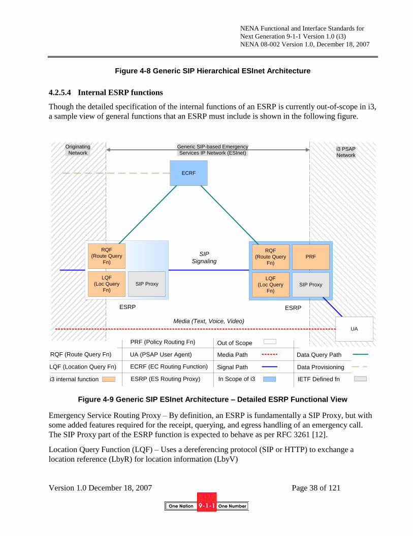
NENA Functional and Interface Standards for
Next Generation 9-1-1 Version 1.0 (i3)
NENA 08-002 Version 1.0, December 18, 2007
Version 1.0 December 18, 2007 Page 38 of 121
Figure 4-8 Generic SIP Hierarchical ESInet Architecture
4.2.5.4 Internal ESRP functions
Though the detailed specification of the internal functions of an ESRP is currently out-of-scope in i3,
a sample view of general functions that an ESRP must include is shown in the following figure.
Originating
Network
Generic SIP-based Emergency
Services IP Network (ESInet)i3 PSAP
Network
UA
Media (Text, Voice, Video)
ECRF (EC Routing Function)
UA (PSAP User Agent)
ESRP (ES Routing Proxy) In Scope of i3
Signal Path
Media Path Data Query Path
Data Provisioning
LQF
(Loc Query
Fn)
SIP Proxy
PRF
ESRP
LQF
(Loc Query
Fn)
SIP Proxy
ESRP
IETF Defined fn
SIP
Signaling
RQF
(Route Query
Fn)
RQF
(Route Query
Fn)
ECRF
i3 internal function
RQF (Route Query Fn)
LQF (Location Query Fn)
PRF (Policy Routing Fn) Out of Scope
Figure 4-9 Generic SIP ESInet Architecture – Detailed ESRP Functional View
Emergency Service Routing Proxy – By definition, an ESRP is fundamentally a SIP Proxy, but with
some added features required for the receipt, querying, and egress handling of an emergency call.
The SIP Proxy part of the ESRP function is expected to behave as per RFC 3261 [12].
Location Query Function (LQF) – Uses a dereferencing protocol (SIP or HTTP) to exchange a
location reference (LbyR) for location information (LbyV)

NENA Functional and Interface Standards for
Next Generation 9-1-1 Version 1.0 (i3)
NENA 08-002 Version 1.0, December 18, 2007
Version 1.0 December 18, 2007 Page 39 of 121
Routing Query Function (RQF) – Uses the LoST protocol to find a tentative list of next hops given
the location information
Policy Routing Function (PRF) – Uses the policy of the destination PSAP, PSAP state, congestion
state, time of day, etc to determine choose one of the next hops that will receive the call.
4.2.6 End to End generic SIP emergency call architecture
The following figure shows an end-to-end functional architecture based on a generic SIP solution.
SIP Proxy
UA
ESRP
ECRFLIS
UA
ESRP
ECRF
Originating
Network
Emergency Services
IP Network (ESInet)i3 PSAP
Network
SIP
Signaling
Media (Text, Voice, Video)
ECRF (EC Routing Function)
UA (User Agent)
ESRP (ES Routing Proxy)
In Scope of i3 Signal Path
Media Path Data Query Path
Data Provisioning
LIS (Loc. Info. Srvr.)
Out of Scope
Figure 4-10 Generic SIP ESInet Architecture – End-to-End Example (shows general SIP
trapezoid w/single ECRF)
A user agent will use a Location Acquisition Protocol to access a LIS for location information. The
user agent queries the ECRF using LoST to obtain a PSAP/ESRP URI, the local dial string for that
location (e.g. 9-1-1) and a confirmation that the location provided by the LIS is valid.
A high level call flow within this functional architecture would go as follows:
1. The calling UA requests its location information from the LIS (typically at bootstrap);
NENA Functional and Interface Standards for
Next Generation 9-1-1 Version 1.0 (i3)
NENA 08-002 Version 1.0, December 18, 2007
Version 1.0 December 18, 2007 Page 40 of 121
2. The calling UA requests routing and dial string/service URNs information based on the
provided location from the designated ECRF within the Origination Network;
3. The calling UA recognizes the dial string in the dialed digits as an emergency call;
4. The calling UA requests current location from the LIS, and re-queries the ECRF using the
updated location to get new routing information.
5. The calling UA attaches location and service URN to the signaling message and forwards the
call to the designated SIP Proxy;
6. The Origination Network SIP Proxy forwards the call to the designated ESRP;
7. The near-end ESRP uses the provided location and service URN to request further refined
routing and services information within the ESInet through the ESInet‟s ECRF (a Forest
Guide as defined in [60]may be needed to find the terminating ECRF);
8. The near-end ESRP forwards the call to the far-end ESRP as per ECRF directives;
9. Far-end ESRP requests final routing and services information from the ECRF and forwards
the call to the terminating UA (an i3 PSAP, Responder, Government or any other supported
service);
10. Media is established between originating and terminating UAs. The call is processed.
4.3 Relationship of NENA i3 to IMS Standards within 3GPP
Many carriers, including wireline, wireless, VoIP and others, are deciding to deploy IP Multimedia
Subsystem (IMS)-based systems for call control. IMS has two possible roles in the i3 architecture:
A source of calls. i3 and IMS emergency call architecture must be aligned so that IMS
standards can be used to present calls to an ESInet;
An implementation of an ESInet. Some IP PSAPs or their contractors may wish to use IMS
components as the implementation of an ESInet. The i3 architecture for the ESInet must be
compatible with a subset of the IMS architecture to allow such use.
The Stage 2 service description for emergency calls in the IP Multimedia Core Network Subsystem
for originating networks is provided in 3GPP 23.167 Technical Specification Group Services and
System Aspects, IMS emergency sessions 23.167[64]. Section 4.3.3 provides an example of how the
3GPP IMS emergency calling functionality can be extended to support i3 emergency call routing via
the RDF. Section 4.3.4 provides and example of how entities defined in 23.167 for the IMS
originating network could be extended to support an IMS based ESInet.
4.3.1 3GPP Functional Entities
The IMS architecture includes a number of key elements. The following elements play a role in the
routing of emergency calls, as defined in 3GPP TS 23.167:
NENA Functional and Interface Standards for
Next Generation 9-1-1 Version 1.0 (i3)
NENA 08-002 Version 1.0, December 18, 2007
Version 1.0 December 18, 2007 Page 41 of 121
User Equipment (UE): The 3GPP term for IP client or endpoint.
Call Session Control Function (CSCF): This functional element is key to call and session control
in an IMS architecture environment. There are a number of different kinds of CSCFs that are
responsible for various aspects of call/session control.
Proxy CSCF (P-CSCF): The P-CSCF is the first contact point within the IMS Control Network.
The P-CSCF behaves like a Proxy, as defined in IETF RFC 3261[12], in that it accepts requests and
either processes them internally or passes them on. The P-CSCF is the IMS network entity that is
responsible for detecting requests for emergency sessions, and forwarding those requests to an
Emergency CSCF (E-CSCF) in the same network.
Emergency CSCF (E-CSCF): The E-CSCF handles certain aspects of emergency sessions, e.g.,
routing of emergency requests to the correct Emergency Services Network or directly to the
appropriate PSAP.
Location Retrieval Function (LRF): The IMS associated functional entity that handles the retrieval
of location information for the emergency caller including, where required, interim location
information, initial location information and updated location information. The LRF may interact
with a separate RDF or contain an integrated RDF in order to obtain routing information for an
emergency call..
Routing Determination Function (RDF): The IMS-associated functional entity, which may be
integrated in a Location Server (e.g. GMLC) or in an LRF and provides the proper outgoing address
to the E-CSCF for routing the emergency request towards a PSAP. It can interact with a location
functional entity (e.g. GMLC) to manage ESQK allocation and management and deliver location
information to the PSAP.
IP-Connectivity Access Network (IP-CAN): The IP-CAN is the collection of network entities and
interfaces that provides the underlying IP transport connectivity between the UE and the IMS
entities. One example of an IP-CAN is General Packet Radio Server (GPRS), as described in 3GPP
TS 23.060 [65]. The IP-CAN may play a role in location retrieval.
4.3.2 Additional Functional Entities in Support of an IMS-based ESInet
In addition, the following terms are defined for use within this document:
Emergency Services Routing Proxy (ESRP) – From the perspective of an IMS-based ESInet, this
element is a combination of the following IMS functional entities:
E-CSCF;
S-CSCF;
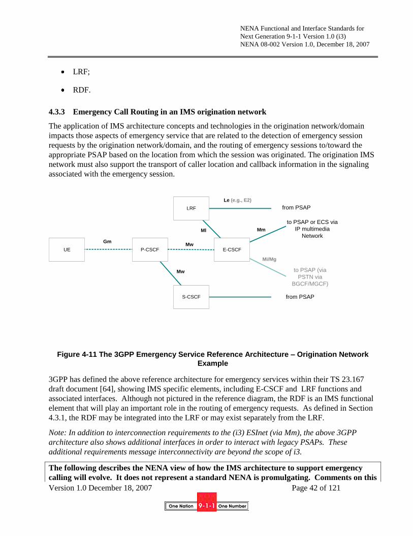
NENA Functional and Interface Standards for
Next Generation 9-1-1 Version 1.0 (i3)
NENA 08-002 Version 1.0, December 18, 2007
Version 1.0 December 18, 2007 Page 42 of 121
LRF;
RDF.
4.3.3 Emergency Call Routing in an IMS origination network
The application of IMS architecture concepts and technologies in the origination network/domain
impacts those aspects of emergency service that are related to the detection of emergency session
requests by the origination network/domain, and the routing of emergency sessions to/toward the
appropriate PSAP based on the location from which the session was originated. The origination IMS
network must also support the transport of caller location and callback information in the signaling
associated with the emergency session.
Figure 4-11 The 3GPP Emergency Service Reference Architecture – Origination Network
Example
3GPP has defined the above reference architecture for emergency services within their TS 23.167
draft document [64], showing IMS specific elements, including E-CSCF and LRF functions and
associated interfaces. Although not pictured in the reference diagram, the RDF is an IMS functional
element that will play an important role in the routing of emergency requests. As defined in Section
4.3.1, the RDF may be integrated into the LRF or may exist separately from the LRF.
Note: In addition to interconnection requirements to the (i3) ESInet (via Mm), the above 3GPP
architecture also shows additional interfaces in order to interact with legacy PSAPs. These
additional requirements message interconnectivity are beyond the scope of i3.
The following describes the NENA view of how the IMS architecture to support emergency
calling will evolve. It does not represent a standard NENA is promulgating. Comments on this
LRF
P-CSCFUE E-CSCF
S-CSCF from PSAP
to PSAP or ECS via
IP multimedia
Network
to PSAP (via
PSTN via
BGCF/MGCF)
from PSAP
Le (e.g., E2)
Ml
Mw
Mm
Mi/Mg
GmMw

NENA Functional and Interface Standards for
Next Generation 9-1-1 Version 1.0 (i3)
NENA 08-002 Version 1.0, December 18, 2007
Version 1.0 December 18, 2007 Page 43 of 121
section would be particularly appreciated. As IMS standards evolve, this text will be revised to
conform to those specifications.
To support emergency call routing, a P-CSCF in the origination network (home or visited) must
detect an emergency session establishment request, and select an E-CSCF in the same network to
handle that request (The mechanism by which the P-CSCF selects the E-CSCF is not standardized in
the current version of TS 23.167.). The P-CSCF will prioritize emergency sessions over non-
emergency sessions. Upon receiving a request for an emergency session from the P-CSCF, the E-
CSCF in the origination network will determine whether location information is present, or needs to
be retrieved. In the context of the i3 solution call flow illustrated below, it is assumed that location
information will be included in session establishment signaling from the endpoint, and that the RDF
is integrated into the LRF. The E-CSCF queries an integrated LRF/RDF to obtain routing
information for the call. To support routing of emergency calls in an i3 solution environment, the
LRF/RDF will need to interact with an ECRF to identify the location-based routing destination for
the call. The ECRF maps the location information provided in the routing request from the
LRF/RDF into either a PSAP URI or an ESRP URI, as described in Section 4.2.4. This call flow is
depicted in Figure 5-3.
Figure 4-12 i3 Solution Emergency Call Routing in IMS-based Originating Network/Domain

NENA Functional and Interface Standards for
Next Generation 9-1-1 Version 1.0 (i3)
NENA 08-002 Version 1.0, December 18, 2007
Version 1.0 December 18, 2007 Page 44 of 121
1. The user initiates an emergency call. The UE detects the emergency session establishment
request by evaluating the SIP URI or dialed number, and generates an emergency session
establishment request that includes an emergency session indication, an Emergency/Public
User Identifier, the UE‟s location information (which is assumed to be available in this
example call flow), and the Tel URI associated with the Public User Identifier, if available.
2. The UE sends a SIP INVITE with an emergency indication to the P-CSCF. In this example, it
is assumed that location information is present in the INVITE.
3. The P-CSCF detects the emergency session request, based on the information provided in the
INVITE message, and selects an E-CSCF in the same network to handle the session. The P-
CSCF then forwards the emergency session establishment there by passing the INVITE to the
E-CSCF.
4. The E-CSCF interacts with an LRF/RDF to obtain routing information, passing the location
information to the LRF/RDF.
5. To obtain the appropriate i3 routing data (i.e., PSAP or ESRP address) for the emergency call
based on the caller‟s location, the LRF/RDF must interact with an i3 ECRF and its supporting
data.
6. The location-based routing information, consisting of the set of PSAP or ESRP URIs
obtained by the LRF/RDF, is returned to the E-CSCF.
7. The E-CSCF uses the routing information provided in step 6 to forward the INVITE message
containing location information and a callback number (assuming one was provided in the
initial session establishment signaling), to the appropriate ESInet determined by the
PSAP/ESRP URI.
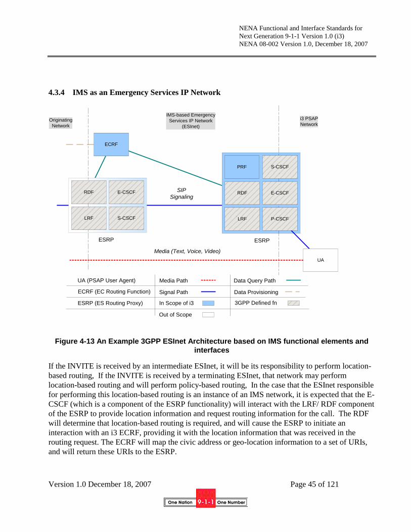
NENA Functional and Interface Standards for
Next Generation 9-1-1 Version 1.0 (i3)
NENA 08-002 Version 1.0, December 18, 2007
Version 1.0 December 18, 2007 Page 45 of 121
4.3.4 IMS as an Emergency Services IP Network
Figure 4-13 An Example 3GPP ESInet Architecture based on IMS functional elements and
interfaces
If the INVITE is received by an intermediate ESInet, it will be its responsibility to perform location-
based routing, If the INVITE is received by a terminating ESInet, that network may perform
location-based routing and will perform policy-based routing, In the case that the ESInet responsible
for performing this location-based routing is an instance of an IMS network, it is expected that the E-
CSCF (which is a component of the ESRP functionality) will interact with the LRF/ RDF component
of the ESRP to provide location information and request routing information for the call. The RDF
will determine that location-based routing is required, and will cause the ESRP to initiate an
interaction with an i3 ECRF, providing it with the location information that was received in the
routing request. The ECRF will map the civic address or geo-location information to a set of URIs,
and will return these URIs to the ESRP.
Originating
Network
IMS-based Emergency
Services IP Network
(ESInet)
i3 PSAP
Network
UA
SIP
Signaling
Media (Text, Voice, Video)
ECRF (EC Routing Function)
UA (PSAP User Agent)
ESRP (ES Routing Proxy) In Scope of i3
Signal Path
Media Path Data Query Path
Data Provisioning
LRF P-CSCF
E-CSCFRDF
ESRP
LRF S-CSCF
E-CSCFRDF
ESRP
3GPP Defined fn
SIP
Signaling
S-CSCFPRF
ECRF
Out of Scope
NENA Functional and Interface Standards for
Next Generation 9-1-1 Version 1.0 (i3)
NENA 08-002 Version 1.0, December 18, 2007
Version 1.0 December 18, 2007 Page 46 of 121
The resulting location-based routing information in an intermediate ESInet consists of a set of ESRP
URIs. The ESRP will send session establishment messages forward toward an ESRP identified in
the routing information obtained from the ECRF, essentially following step 7 of the call flow
illustrated in Figure 4-12.
The resulting location-based routing information in a terminating ESInet consists of a PSAP URI.
The RDF component of the ESRP will subsequently interact with the PRF component of the ESRP
to identify any PSAP/policy-based routing resolution characteristics that might change the
destination address that should be used to route the call. The ESRP will forward the INVITE
message toward the destination PSAP identified in the routing information determined by the RDF
component. The INVITE will include the location and potentially callback information received by
the ESRP previously. Figure 4-13 illustrates a scenario where the originating network sends an
emergency session request to an IMS-based ESInet acting as a terminating ESInet, and the IMS
Network performs both location-based routing and PSAP/policy-based routing.
4.3.5 Backup/Default Routing in an IMS-based i3 Solution Environment
The i3 solution also supports a default routing capability. As described in Section 5.1.6, if routing
information cannot be determined by the ECRF because location information is not available, a pre-
provisioned default URI may be used by the querying entity to determine the routing for the next hop
of the call. Another possibility is that the ECRF will provide the address of a default PSAP/call
center in its routing response, if it is unable to determine the actual target PSAP/ESRP URI based on
the information provided in the routing request. If an IMS origination network/domain and/or
ESInet are part of the i3 solution architecture, it will also have to support a mechanism for default
routing of emergency session requests for scenarios where location information cannot be
determined, or where the location/routing request to the LRF/RDF fails. One of the architectural
principles listed in TS 23.167 is that the IMS core network shall provide the possibility to route to a
default answering point in scenarios where the local PSAP cannot be determined. TS 23.167 also
specifies that, upon receiving an initial request for an emergency session from a P-CSCF, the E-
CSCF shall determine the default PSAP destination, if routing based on the UE‟s location is
required, but the location is unknown. However, there are no procedures defined at this time that
specify how this default destination will be determined.
4.4 Relationship of NENA i3 to ATIS Standards
ATIS has several committees and standards development activities that relate to the emerging
Emergency Services IP Network. ATIS intends to develop Stage 3 standards from this NENA work.
Below is a sample, but not necessarily exhaustive, list of relevant ATIS committees and their
associated standards development activities.
Emergency Services Interconnection Forum (ESIF)
NENA and ATIS initiated ESIF with the support of the Federal Communications Commission
(FCC) in 2002. ESIF was formed as a cooperative effort between NENA and ATIS. Its initial
focus was to identify and recommend resolution of interoperability issues relating to the
introduction of E9-1-1 Wireless Phase 2. ESIF has since expanded its role to be the primary

NENA Functional and Interface Standards for
Next Generation 9-1-1 Version 1.0 (i3)
NENA 08-002 Version 1.0, December 18, 2007
Version 1.0 December 18, 2007 Page 47 of 121
committee within ATIS to champion and promote topics and standards related to Emergency
Services at large. ESIF Emergency Services Network Interfaces (ESNI) Task Force 34 has
defined two data communications standards to be used in Emergency Services IP Networks.
Note that, the ESNI framework is an ATIS Standard that defines an ESNet. The Emergency
Services Messaging Interface (ESMI) is an ATIS-PP-0500002-200X [69]. The Emergency
Information Services Interface (EISI) will also become a Trial Use American National
Standard (ANS) for Telecommunications. Finally, the NGES subcommittee is coordinating
emergency services standards development activities within ATIS and is also providing ESIF
liaison(s) with other global SDOs.
Technology and Operations Council (TOPS)
Established by the ATIS Board of Directors, TOPS identifies the telecommunications
industry‟s most pressing technical and operational standards development priorities, and
coordinates standardization efforts industry-wide to produce interoperable, implementable,
end-to-end solutions. In May 2006, ATIS released its third Next Generation Network (NGN)
standard document entitled "ATIS Next Generation Network (NGN) Framework, Part III:
Standards Gap Analysis, May 2006." [67] Building upon the previous two standard
documents, in particular the requirements identified in Part I and network enablers identified
in Part II, Part III identifies the global standards development activities and assesses major
gaps for the NGN global standard across other standards development priorities as specified
by the TOPS Council. Note that Next Generation Emergency Services was specifically
addressed as a priority in this document for both ESIF and PTSC.
Packet Technologies and Systems Committee (PTSC)
The PTSC develops and recommends standards and technical reports related to
telecommunications network services, architectures, and signaling, in addition to related
subjects under consideration in other North American and international SDOs. The PTSC
recently issued the IP Network-to-Network Interface (NNI) Standard for VoIP: ATIS-PP-
1000009.2006 [68]. The NNI Standard for VoIP is pursuing internetworking Voice Call
Continuity (VCC) standards and will address standards specifically targeting VoIP call
continuity for Emergency Services in North America.
Wireless Technologies and Systems Committee (WTSC)
The WTSC develops and recommends standards and technical reports related to wireless
and/or mobile services and systems, including service descriptions and wireless technologies.
The WTSC develops and recommends positions on related subjects under consideration in
other North American, regional and international SDOs. The WTSC, along with TIA TR45.2,
has developed the joint TIA/ATIS Draft ANS J-STD-36-B: Enhanced Wireless 9-1-1 Phase 2
[71]. The WTSC plays an integral role in defining the evolution of emergency services in
next generation wireless networks.
Other ATIS Committees
Other ATIS committees such as the Network Performance, Reliability and Quality (PRQC),
the Telecommunications Management and Operations (TMOC), and other committees may

NENA Functional and Interface Standards for
Next Generation 9-1-1 Version 1.0 (i3)
NENA 08-002 Version 1.0, December 18, 2007
Version 1.0 December 18, 2007 Page 48 of 121
also play roles in evolving standards for emergency services in their committees‟ area of
expertise.
4.5 Legacy Gateway Architectures -- Examples in i3
Though i3 is commonly defined as IP end-to-end, Industry has acknowledged that there will continue
to be a percentage of wireline and wireless (circuit switched) originating networks deployed after
emergency service networks and PSAPs have evolved to support the i3 Solution. Since any i3 PSAP
will need to be able to receive emergency calls which originate on these legacy networks, there is an
acknowledgement that gateways will be required.
4.5.1 Legacy Wireline Origination Network
Switch ESRPLegacy
GatewayPSAPPhone
ECRF
SIPTDM SIP
[PIDF-LO] [PIDF-LO]
Legacy Wireline Origination Network ESInet
LIS
(Replaces
ALI)
[TN]
i3 PSAP
Figure 4-14 Example Legacy Wireline Origination Network to ESInet (LbyV)

NENA Functional and Interface Standards for
Next Generation 9-1-1 Version 1.0 (i3)
NENA 08-002 Version 1.0, December 18, 2007
Version 1.0 December 18, 2007 Page 49 of 121
Although NG9-1-1 in general, and i3 in specific, is the future, legacy origination networks, and
specifically legacy wireline origination will be with i3 for a long time. Thus i3 must specify how
legacy wireline origination is handled.
Consistent with this specification, all calls (including legacy wireline originated calls) are routed
(using the LoST mechanism), and arrive as IP with location and caller information6 (e.g., callback
number) in the signaling. This means there is a legacy gateway with a PSTN interface towards the
origination network, and an IP interface towards the ESInet. Logically, the legacy gateway resides
between the origination network and the ESInet. The PSTN side has trunk interfaces equivalent to a
selective router‟s, commonly SS7, but allowing CAMA or even ISDN. The IP side produces SIP call
signaling as described in this document.
Unlike an IP origination, the legacy wireline signaling will not have location information attached in
PIDF-LO form. The legacy gateway must obtain the location information based on the calling
number/ANI it receives with the call. To support legacy wireline origination, a LIS will logically
replace the ALI database. The LIS will store location information keyed by TN and provide a PIDF-
LO to the gateway. The relationship between the gateway and LIS is static and provisioning will be
used to introduce the LIS to the gateway.
Note: When roles and responsibilities for the legacy gateway and LIS are determined, a re-
examination of the provisioning issues may be needed.
The legacy gateway takes the location it obtains from the LIS, submits it to the ECRF via LoST and
obtains an ESRP URI to route the call onward. Again, the relationship between the legacy gateway
and the ECRF is provisioned.
The legacy gateway inserts the PIDF-LO into the SIP signaling, along with the ESRP URI and routes
the call as it would any IP origination. The signaling will also include caller information in the
From: and/or P-Asserted-Identity headers.
While location by value is preferred, the LIS may return a location reference, which would be used in
an analogous way as a location reference would be used in IP origination networks. The gateway
would dereference to obtain a location value, use that value to query the ECRF, and pass the
reference in the SIP signaling towards the ESRP.
6 Further discussion is needed to address the content of the caller information, such as delivery of the
subscriber name that is delivered to an i3 PSAP in signaling associated with an emergency call.

NENA Functional and Interface Standards for
Next Generation 9-1-1 Version 1.0 (i3)
NENA 08-002 Version 1.0, December 18, 2007
Version 1.0 December 18, 2007 Page 50 of 121
4.5.2 Legacy Wireless/Circuit Switched (CS) Origination Network
Figure 4-15 Example Wireless/CS Origination Network to ESInet (LbyR)
As in the case of legacy wireline origination networks, it is expected that legacy wireless/CS
origination will need to interwork with i3 for a long time. Thus i3 must specify how legacy
wireless/CS origination is handled.
Consistent with this specification, all calls (including legacy wireless/CS originated calls) are routed
using the ECRF, and arrive as IP with location and callback number in the signaling. This means
there is a legacy gateway with a PSTN interface towards the origination wireless/CS network, and an
IP interface towards the ESInet. Logically, the legacy gateway resides between the origination
network and the ESInet. The PSTN side has trunk interfaces equivalent to a selective router‟s,
commonly SS7, but allowing CAMA. The IP side produces SIP call signaling as described in this
document.
There are several ways a legacy wireless/CS network could be connected to an ESInet. One way is
to maintain maximum compatibility with the current wireless/CS system. A LIS is introduced
between the MPC/GMLC and the gateway. The gateway queries the LIS for location during call
setup, using the ESRK/ESRD as a key. The LIS returns the current location, which in many cases is
the cell site/sector7 location (often in civic form). The relationship between the gateway and LIS is
static and provisioning will be used to introduce the LIS to the gateway.
Note: When roles and responsibilities for the legacy gateway and LIS are determined, a re-
examination of the provisioning issues may be needed. More details are developing within the
NENA NGTPC Committee Legacy Wireless document.
7 Cell site/sector is considered coarse location.
MSC/BSC ESRP
SMLC
Legacy
Gateway
ECRF
PSAP
MPC/
GMLC
UE
SIP
PDE
TDM SIP
(e.g., E2/PAM)
Wireless/CS Origination Network
[Loc_Ref] [Loc_Ref]
LIS
(Replaces
ALI)
[ESRK]
ESInet i3 PSAP

NENA Functional and Interface Standards for
Next Generation 9-1-1 Version 1.0 (i3)
NENA 08-002 Version 1.0, December 18, 2007
Version 1.0 December 18, 2007 Page 51 of 121
The legacy gateway takes the location it obtains from the LIS, submits it to the ECRF via LoST and
obtains an ESRP URI to route the call onward. Again, the relationship between the legacy gateway
and the ECRF is provisioned.
The LIS is responsible for determining if the wireless/CS network is Phase II capable. If it is, the
location returned by the LIS may be just a reference, which the gateway must dereference to obtain a
value it can use to query the ECRF; it may include the value as well as the reference. The
dereferencing function is expected to involve interaction with elements in the legacy wireless
network (e.g., MPC/GMLC) where Phase II location information is maintained. The reference will
be added to the SIP signaling. The gateway routes the call as it would with any IP origination. The
signaling would include callback number in the From: and/or P-Asserted-Identity headers. ESRPs
that are traversed by the call must repeat the dereferencing process, using the resulting location value
to query the ECRF. They will then route the call forward. The PSAP must also perform
dereferencing and final routing, potentially involving an interaction with the ECRF.
If the LIS determines that the origination network is Phase I capable only, then it will return a
location value, which will be used to query the ECRF and placed in the SIP signaling. This location
value (formatted as civic location information in a PIDF-LO) will be included in outgoing SIP
signaling, and will be used by ESRPs in the call path to interact with the ECRF to determine
subsequent routing for the call. The location value will also be delivered to the PSAP with the call,
along with callback number.
As the function of providing location for wireless/CS origination calls is typically regulation-driven,
it may not be available in some countries where such mandates are not enforced (e.g., Canada).
4.6 Service Architecture
A Service Oriented Architecture (SOA) is a way of organizing and using distributed (functional)
capabilities to solve system needs (requirements). It is a composition model that connects the
functional capabilities of applications, called services, through well-defined interfaces and contracts
between these services.
“Foundation services” are well-known services such that service consumer entities are not
discovered in the registry, but are part of every Emergency Services Network.
Most external interfaces defined for an IP-enabled PSAP will be expressed as services that are part
of an Emergency Services IP Network service architecture system
4.6.1 Service Definitions
A service has an associated well-defined service interface which is used for service consumption i.e.,
making use of a capability. Services “live inside” distributed processing entities.
A service‟s interface is defined in a way that is independent of the hardware platform, the operating
system, hosting middleware and the programming language used to implement the service. This
allows services, built on a variety of systems, to interact with each other in a uniform and universal
manner.
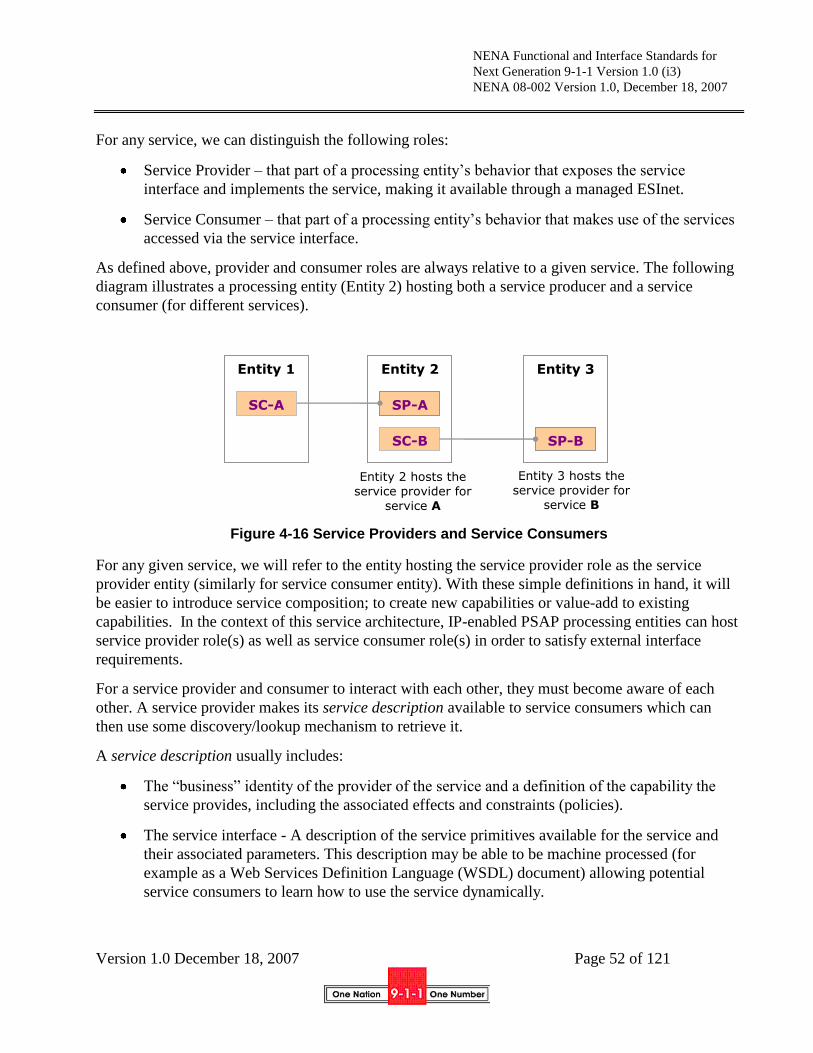
NENA Functional and Interface Standards for
Next Generation 9-1-1 Version 1.0 (i3)
NENA 08-002 Version 1.0, December 18, 2007
Version 1.0 December 18, 2007 Page 52 of 121
For any service, we can distinguish the following roles:
Service Provider – that part of a processing entity‟s behavior that exposes the service
interface and implements the service, making it available through a managed ESInet.
Service Consumer – that part of a processing entity‟s behavior that makes use of the services
accessed via the service interface.
As defined above, provider and consumer roles are always relative to a given service. The following
diagram illustrates a processing entity (Entity 2) hosting both a service producer and a service
consumer (for different services).
Figure 4-16 Service Providers and Service Consumers
For any given service, we will refer to the entity hosting the service provider role as the service
provider entity (similarly for service consumer entity). With these simple definitions in hand, it will
be easier to introduce service composition; to create new capabilities or value-add to existing
capabilities. In the context of this service architecture, IP-enabled PSAP processing entities can host
service provider role(s) as well as service consumer role(s) in order to satisfy external interface
requirements.
For a service provider and consumer to interact with each other, they must become aware of each
other. A service provider makes its service description available to service consumers which can
then use some discovery/lookup mechanism to retrieve it.
A service description usually includes:
The “business” identity of the provider of the service and a definition of the capability the
service provides, including the associated effects and constraints (policies).
The service interface - A description of the service primitives available for the service and
their associated parameters. This description may be able to be machine processed (for
example as a Web Services Definition Language (WSDL) document) allowing potential
service consumers to learn how to use the service dynamically.
Entity 1 Entity 3
SP-B
Entity 2
SP-A
SC-B
Entity 2 hosts the service provider for
service A
Entity 3 hosts the service provider for
service B
SC-A
NENA Functional and Interface Standards for
Next Generation 9-1-1 Version 1.0 (i3)
NENA 08-002 Version 1.0, December 18, 2007
Version 1.0 December 18, 2007 Page 53 of 121
The service access point(s) - Specifies the network address of the processing entity that
exposes the service interface. There may be more that one such address corresponding to
various “flavors” of the service such as the different bindings under which the service is
made available. Bindings are used to define the access mechanism used when a service is
invoked (e.g., SOAP/HTTP, JMS/Messaging, and CORBA/IIOP).
For any given service, some or all of the above information (known as service metadata) can already
be known to a service consumer (i.e. specified at design time). It can also be dynamically determined
through a process called service discovery.
Whatever mechanism a service consumer uses for service discovery, the service description must
have previously been made available through some activity, generally known as service registration.
4.6.2 Service Registry
A “Service registry” is a logically centralized directory of services. The registry provides a central
place where service providers can publish new services and service consumers can discover those
services.
The Service Registry is a foundation service of a service architecture that supports registration
(storage), lookup and discovery of service descriptions. Service management is an important aspect
of service architectures and the Service Registry is one component of it.
One example of a Service Registry is the Universal Description Discovery & Integration [72] registry
published by the Organization for the Advancement of Structured Information Standards (OASIS).
4.6.2.1 Registration
Service registration will usually be an off-line activity, but may also be dynamic under certain
circumstances.
4.6.2.2 Discovery
Discovery includes determination of the access point, the binding and the service interface. For
many services, all of this information can be obtained from the service registry. Some
implementations will not discover service interfaces, but will be programmed for specific interfaces.
Similarly, bindings may be decided in advance instead of discovered.
Service discovery can be a design-time activity i.e. when designing consumer applications. This
might be considered more “lookup” than “discovery”.
Service discovery can also be a run-time process; like when applications need to dynamically
discover how to consume a service they did not know about beforehand. This is true discovery.
The end-result is the same however, indicating if a provider exists for the given service, obtaining
the technical specification for the service (possibly machine processed) and finding out at what
network address the service may be accessed.

NENA Functional and Interface Standards for
Next Generation 9-1-1 Version 1.0 (i3)
NENA 08-002 Version 1.0, December 18, 2007
Version 1.0 December 18, 2007 Page 54 of 121
4.6.3 A closer look at the service architecture
A system architecture organizes and uses distributed (functional) capabilities to solve system needs
(requirements), and services are the mechanisms that relate needs to capabilities.
Some services will represent specific non-decomposable capabilities. These are standalone services.
One example would be the National Crime Information Center (NCIC) inquiry service.
Service composition is used to bring together multiple services (standalone or composed) to satisfy
more complex or higher-level needs.
The following are a few well-known composition patterns:
Correlation – a service correlates information or events acquired/provided by other services
and makes the result of correlation, synthesized information or events, available to its service
consumers.
Sequencing – a service that triggers other service providers in some particular sequence to get
some desired effect – like in the case of a workflow sequence where each workflow step is
represented as a service provider.
Aggregation – a service acquires and gathers information from different service providers and
makes the aggregated (by containment or reference) information available to its service
consumers.
Cache – a service that “remembers” information or events acquired from or produced by
other services for deferred on-demand restitution to its service consumers.
Proxy – a service that plays the “go between” role for a service consumer and the ultimate
(real) service provider.
Mediation – a service that provides a uniform appearance to a service consumer for a set of
services with a disparate set of service interfaces.
The above service composition patterns are quite useful in coordinated collaborative service
architectures such as that envisioned for the ESInet.
Here are a couple of examples that illustrate this point. The diagrams below illustrate two alternative
models for providing a mediated ALI service: the first model illustrates the ATIS.ESIF.TF34 ESMI
view of mediation and the second illustrates a (native) web service view of mediation. Note that both
of the diagrams refer to previously defined utility components, but these are used only for their value
as functional model elements.
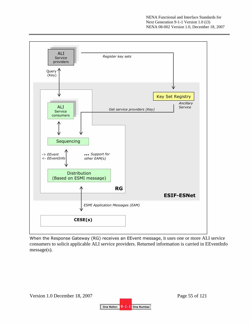
NENA Functional and Interface Standards for
Next Generation 9-1-1 Version 1.0 (i3)
NENA 08-002 Version 1.0, December 18, 2007
Version 1.0 December 18, 2007 Page 55 of 121
Figure 4-17 Mediated ALI as in ESIF/TF34/ESMI
When the Response Gateway (RG) receives an EEvent message, it uses one or more ALI service
consumers to solicit applicable ALI service providers. Returned information is carried in EEventInfo
message(s).
CESE(s)
ALI Service
consumers
ALI Service
providers
Key Set Registry
Sequencing
Distribution (Based on ESMI message)
… Support for
other EAM(s)
ESMI Application Messages (EAM)
Ancillary Service
RG
ESIF-ESNet
-> EEvent <- EEventInfo
Register key sets
Query (Key)
Get service providers (Key)
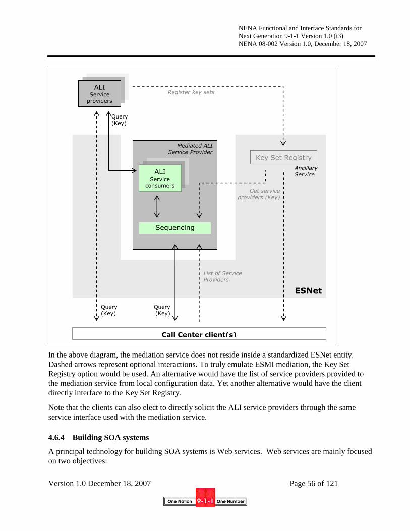
NENA Functional and Interface Standards for
Next Generation 9-1-1 Version 1.0 (i3)
NENA 08-002 Version 1.0, December 18, 2007
Version 1.0 December 18, 2007 Page 56 of 121
Figure 4-18 Mediated ALI using a native web service provider
In the above diagram, the mediation service does not reside inside a standardized ESNet entity.
Dashed arrows represent optional interactions. To truly emulate ESMI mediation, the Key Set
Registry option would be used. An alternative would have the list of service providers provided to
the mediation service from local configuration data. Yet another alternative would have the client
directly interface to the Key Set Registry.
Note that the clients can also elect to directly solicit the ALI service providers through the same
service interface used with the mediation service.
4.6.4 Building SOA systems
A principal technology for building SOA systems is Web services. Web services are mainly focused
on two objectives:
Call Center client(s)
ALI Service
consumers
ALI Service
providers
Key Set Registry
Sequencing
Ancillary Service
ESNet
Mediated ALI Service Provider
Query (Key)
Query (Key)
Query (Key)
Register key sets
Get service providers (Key)
List of Service Providers

NENA Functional and Interface Standards for
Next Generation 9-1-1 Version 1.0 (i3)
NENA 08-002 Version 1.0, December 18, 2007
Version 1.0 December 18, 2007 Page 57 of 121
The wire-level protocols that ensure runtime interoperability between heterogeneous systems.
Web services are based on the exchange of messages using a technology-neutral XML format
(SOAP).
Standards for defining service interfaces (WSDL and XML) independently of the
implementation technology. A standard for defining interfaces also enables interoperability
between tools.
It is generally recognized that using Web services isn‟t the only way to implement an SOA system.
For example, Representational State Transfer (REST) can provide a simpler way of implementing
system capabilities for certain needs.
4.7 Security Architecture
ECRF
ESRPESRP
Originating
NetworkEmergency Services IP Network
(ESInet)i3 PSAP Network
UA
ESRP
Media (Text, Voice, Video)
ECRF (EC Routing Function)
UA (User Agent)
ESRP (ES Routing Proxy)
In Scope of i3
Signal Path
Media Path Data Query Path
Data Provisioning
Optional Query
BCFBCFBCF
SECURITY
DOMAIN1SECURITY
DOMAIN2
(Optional)
SECURITY
DOMAIN3
Out of Scope
Figure 4-19 Security Domains
Additional explanation will be provided in a future edition of this standard

NENA Functional and Interface Standards for
Next Generation 9-1-1 Version 1.0 (i3)
NENA 08-002 Version 1.0, December 18, 2007
Version 1.0 December 18, 2007 Page 58 of 121
5 Description of Call Flow
5.1 Basic 9-1-1 call
SIP Proxy
UA
ESRP
ECRFLIS
UA
ESRP
ECRF
Originating
Network
Emergency Services
IP Network (ESInet)i3 PSAP
Network
SIP
Signaling
Media (Text, Voice, Video)
ECRF (EC Routing Function)
UA (User Agent)
ESRP (ES Routing Proxy)
In Scope of i3 Signal Path
Media Path Data Query Path
Data Provisioning
LIS (Loc. Info. Srvr.)
Out of Scope Optional
Figure 5-1 Generic SIP Call Architecture
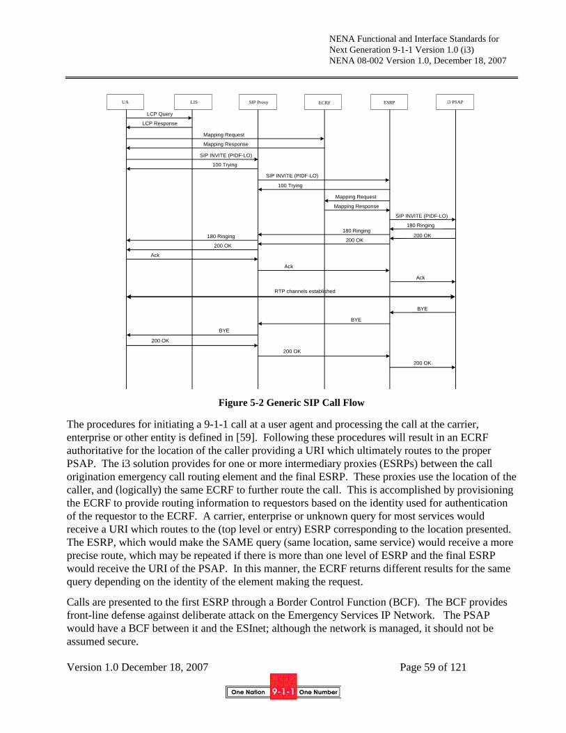
NENA Functional and Interface Standards for
Next Generation 9-1-1 Version 1.0 (i3)
NENA 08-002 Version 1.0, December 18, 2007
Version 1.0 December 18, 2007 Page 59 of 121
Figure 5-2 Generic SIP Call Flow
The procedures for initiating a 9-1-1 call at a user agent and processing the call at the carrier,
enterprise or other entity is defined in [59]. Following these procedures will result in an ECRF
authoritative for the location of the caller providing a URI which ultimately routes to the proper
PSAP. The i3 solution provides for one or more intermediary proxies (ESRPs) between the call
origination emergency call routing element and the final ESRP. These proxies use the location of the
caller, and (logically) the same ECRF to further route the call. This is accomplished by provisioning
the ECRF to provide routing information to requestors based on the identity used for authentication
of the requestor to the ECRF. A carrier, enterprise or unknown query for most services would
receive a URI which routes to the (top level or entry) ESRP corresponding to the location presented.
The ESRP, which would make the SAME query (same location, same service) would receive a more
precise route, which may be repeated if there is more than one level of ESRP and the final ESRP
would receive the URI of the PSAP. In this manner, the ECRF returns different results for the same
query depending on the identity of the element making the request.
Calls are presented to the first ESRP through a Border Control Function (BCF). The BCF provides
front-line defense against deliberate attack on the Emergency Services IP Network. The PSAP
would have a BCF between it and the ESInet; although the network is managed, it should not be
assumed secure.
SIP Proxy
ESRP
ECRF
LISUA
i3 PSAP
RTP channels established
Mapping Request
LCP Query
LCP Response
SIP INVITE (PIDF-LO)
Ack
200 OK
SIP INVITE (PIDF-LO)
200 OK
Mapping Response
SIP INVITE (PIDF-LO)
Mapping Request
Mapping Response
100 Trying
100 Trying
180 Ringing
200 OK180 Ringing
200 OK180 Ringing
200 OK
Ack
Ack
BYE
BYE
BYE
200 OK
NENA Functional and Interface Standards for
Next Generation 9-1-1 Version 1.0 (i3)
NENA 08-002 Version 1.0, December 18, 2007
Version 1.0 December 18, 2007 Page 60 of 121
The PSAP receives the call, with the location information attached, from an ESRP. The PSAP proxy
server routes the call to an available call taker (internal PSAP function not part of this specification).
It may be necessary for the PSAP to transfer the call to a secondary PSAP (or PSAPs) for dispatch of
responders based on the location of the caller. The PSAP may use (logically) THE SAME ECRF,
but possibly a different service request, and, because it is authenticated to the ECRF as a PSAP, it
will receive the URI of the secondary PSAP appropriate for the service requested. In this context
“service” is the service request in the LoST protocol. As an example, the original call may be to
urn:service:sos. The PSAP may decide it needs to dispatch the appropriate police agency. It would
query the ECRF with the location of the caller, but with service urn:service:sos.police. Thus the
ECRF provides routing from the carrier (if there is a carrier) to the ESRP, from one level of ESRP to
another, from the lowest level ESRP to the PSAP and from the PSAP to the dispatcher(s). The LoST
protocol uses location + service as input, and provides URI(s) output, and the i3 architecture makes
use of this function for all routing. PSAPs may have other ways to choose a responder when
location-based routing is not used.
It is important to point out that it is LOGICALLY the same ECRF. It may be very appropriate for a
different physical box to provide routing for external entities, with another one for intra-ESInet
routing.
As described in Section 4.5, calls from legacy networks (wireline or wireless) which are not
inherently VoIP-based must undergo signaling interworking (i.e., at a gateway system) to convert the
incoming Multi-Frequency (MF) or Signaling System No. 7 (SS7) signaling to SIP.
In addition, functionality must be applied to legacy emergency calls that will allow the information
provided in call setup signaling by the wireline switch or MSC (e.g., calling number/ANI, ESRK,
cell site/sector) to be used to route a call and provide location to the PSAP. Determination of call
routing for legacy calls will actually involve two functions: a location retrieval function and a
routing determination function. The location retrieval function will be responsible for translating the
information received with a legacy emergency call into location information that could be used as
input to the routing determination function (i.e., a civic address or geo-location). It is assumed that
this function will involve interaction with some type of location database/server.8 In the call flows
shown later the term Location Information Server (LIS) is used. This is to illustrate that the network
could extend the concept of the i2 LIS[3] for this function. The routing determination function (i.e.,
ECRF) would then map the location information obtained via the location retrieval function to a
PSAP URI.
This means that all legacy calls, regardless of origin are routed using the same ECRF, based on
information obtained via a location retrieval function, and arrive at the PSAP as VoIP with location.
If the PSAP determines that another PSAP needs to handle the call, it will need to route a call to that
PSAP. The operation will be a bridge/transfer per Section 5.6.
8 Identification of the specific system(s) that would serve as the “location database/server” is beyond the scope of this document. Network providers should weigh the use of existing database systems, such as existing ALIs and MPCs, vs. the development of new
database systems optimized for this function, taking into consideration factors such as cost, availability and ability to meet business
needs.

NENA Functional and Interface Standards for
Next Generation 9-1-1 Version 1.0 (i3)
NENA 08-002 Version 1.0, December 18, 2007
Version 1.0 December 18, 2007 Page 61 of 121
For mobile callers, regardless of origin network type, the PSAP will have access to a location update
service, which can provide location changes. The location update service will be provided as an on-
demand mechanism or as a subscription (auto-update) mechanism.
If the PSAP determines that another PSAP needs to handle the call, it will need to route a call to that
PSAP. The operation will be a bridge/transfer per Section 5.6
5.1.1 Processing of incoming INVITE transaction at a Border Control Function
If a BCF is integrated with an ESRP, such that a failure of one is equivalent to a failure of the other
(“fate sharing”), and the BCF function is transparent to signaling entities, the only requirement of the
BCF is to maintain Transport Layer Security (TLS [85]) connections with upstream entities who
request TLS connections to the ESRP. If the BCF does not share fate with the ESRP, or is not
transparent to signaling entities, the BCF must operate as a proxy server per RFC3261, must insert a
VIA header in messages as appropriate and must forward calls unconditionally to the ESRP which is
the target of the call. This document does not specify operation of the BCF, but the following
functions could be included in one:
1. Port firewall: only permitting SIP connections to 5060 and SIPS connections to 5061
2. Pinhole firewall for media: Inspection of SDP with opening of pinhole firewalls for
authorized media streams
3. SIP protocol repair: Inspection of SIP messages for conformance to RFC3261 with editing of
messages which do not conform. It is RECOMMENDED that this function attempt to pass
calls in all cases, rather than rejecting calls for not being 3261 compliant.
4. DoS mitigation: Detect known and symptomatic denial of service attacks and filter attack
attempts out of further processing. This includes TCP, UDP and SIP attack mitigation.
5.1.2 Processing of an incoming INVITE transaction at a non-terminal Emergency Services
Routing Proxy
An ESRP will receive a call routed to it via the [59] procedure. The ESRP will:
1. Extract location from the call. If location is not present, skip to step 3 and use a provisioned
default mapping as the Request-URI
2. Map the location using LoST. The ESRP must maintain a persistent TLS/TCP connection to
the ECRF for this purpose. The ESRP credentials used for the TLS authentication identifies
the ESRP as an authorized internal routing element within the Emergency Services IP
Network and the route obtained from this step will be a lower level ESRP9.
3. Perform call congestion control processing per ESRP and PSAP policy. See Section 5.8.
The resulting URI becomes the Request URI for the next hop.
9 The lowest level ESRP is the incoming proxy at a PSAP. This is termed the “terminal” ESRP.

NENA Functional and Interface Standards for
Next Generation 9-1-1 Version 1.0 (i3)
NENA 08-002 Version 1.0, December 18, 2007
Version 1.0 December 18, 2007 Page 62 of 121
4. Add a VIA header per RFC3261
5. Inspect the INVITE for the presence of a Call Identifier (which must be in the form of a
GUID), and include it in the outgoing message
6. Add a Record-Route header per RFC3261 if desired
7. Route the call using the procedures specified in RFC3261 [12] section 16
8. Use persistent TLS connections to downstream proxies.
5.1.3 Processing of an incoming INVITE at a terminal ESRP
The terminal ESRP must accept calls per RFC3261 procedures. The proxy must add a VIA header.
The PSAP RP MUST accept TLS connections. All Record Route requests must be honored. There
are no other EXTERNAL interface requirements.
5.1.4 Policy-based Routing Function routing
At each ESRP, a location based routing function using the ECRF may be applied. In addition, a
Policy Routing function (PRF) must be applied to determine the next hop of the call. The policy is
determined primarily by PSAP management of the PSAP that serves the area the call originates from,
but policy elements from higher level authorities (e.g. the local 9-1-1 Authority or a regional or state
9-1-1 Authority) may be involved, and, if the call is diverted (see Section5.8, Overload) the diversion
PSAP.
Policy includes at least the following inputs:
Location
Time of Day
PSAP State (e.g. out of service, congested, disaster, under attack…)
Caller classification (e.g. mobile/fixed, business/residential, …)
The result of the policy decision is a URI to the next hop (which may be an intermediate ESRP or a
terminal ESRP at the PSAP).
5.1.5 Processing of outgoing INVITE transactions at BCFs and non-terminal ESRPs
Outgoing INVITE transactions must follow procedures in RFC3261. Via headers must be added.
Proxies MUST NOT hide or modify Via headers. Record Route‟s MUST be honored by all
elements. TLS MUST be used within the Emergency Services IP network, and SHOULD be used
with downstream proxies.
An outgoing call MAY have an Incident Identifier and SHOULD have a Call Identifier.

NENA Functional and Interface Standards for
Next Generation 9-1-1 Version 1.0 (i3)
NENA 08-002 Version 1.0, December 18, 2007
Version 1.0 December 18, 2007 Page 63 of 121
5.1.6 Abnormal Cases
There are a number of errors or abnormal conditions (e.g., network failures) that may occur in the
process of routing emergency calls originated by VoIP users to the appropriate i3 PSAP via an
ESInet. This section identifies different error scenarios that may occur in the course of routing an
emergency call to the appropriate PSAP in an i3 environment, and identifies the contingency/default
routing mechanisms that should be invoked at the various i3 functional elements that are impacted by
the abnormal condition or event.
5.1.6.1 Abnormal Conditions Detected at Border Control Function
Text will be provided in a future version of this standard.
5.1.6.2 Abnormal Conditions Detected at the ESRP
This section identifies different error scenarios that may occur in the course of routing an emergency
session request in an i3 environment, and identifies what is expected of the ESRP under those
different scenarios. There are several classes of error/failure scenarios that may be detected at the
ESRP. One class of abnormal conditions is related to the request for routing information that the
ESRP is expected to generate for emergency session requests and send to the appropriate ECRF, and
the processing of the associated response message from the ECRF. This class of error/failure
scenarios includes the following:
The ESRP cannot identify the ECRF (or its network address) to which the routing request
associated with an emergency session request should be directed.
The ESRP has lost the TLS connection to the ECRF.
The ESRP receives an error response from the ECRF that does not contain any routing
information.
The ESRP does not receive any response from the ECRF within a pre-determined period of
time.
In all of these scenarios, the end result is that the ESRP does not receive any routing information
from the ECRF.
If the problem is the inability to establish or maintain a TLS connection with the ECRF, the ESRP
may attempt to send the routing query to a secondary ECRF, provided that an alternative was
returned as part of the discovery process and the appropriate agreements between the ESRP operator
and the ECRF providers exist. The ESRP should first try all secure TLS connections, based on local
policy, then try non-secure connections. If the ESRP is still unable to access the ECRF, it may
default route the call, as described below.
Should one of the other error scenarios described above occur, the ESRP should default route the
call. Default routing may either use a default URI that has been predefined by the ESInet provider,
in cooperation with the interconnected PSAPs, cached information, or a “local ECRF” which has
been populated by caching or provisioning, to route the emergency session request forward.
NENA Functional and Interface Standards for
Next Generation 9-1-1 Version 1.0 (i3)
NENA 08-002 Version 1.0, December 18, 2007
Version 1.0 December 18, 2007 Page 64 of 121
If the ESRP is unable to obtain routing information from an ECRF because the ECRF responded to
the routing query with an error message or because the ECRF failed to respond to the routing query
before the query timer expired, the ESRP shall determine the URI to which to forward the
emergency session request based on local policy. One example of the way that a default URI may
be determined is provided below:
If there is no cached information available for the location information provided in the
incoming INVITE message, or the cached information is no longer valid, the ESRP shall use
a pre-provisioned default URI to forward the emergency session request.
If there is valid cached information available for the location information (or a portion of the
location information provided), the ESRP shall determine, based on configuration data set by
the ESRP operator, whether to use the cached data or default routing data according to the
following criteria:
– The nature of the location information received (i.e., whether it is civic or geo)
– The level at which a match with cached information is achieved (e.g., state, county,
municipality)
– The level of the ESRP (e.g., state-level versus county-level).
Another class of abnormal conditions results from network failures that make routing the emergency
session request to the desired destination (i.e., the primary destination provided in the routing
response) impossible. In this case, the ESRP should use an alternate URI provided in the response
from the ECRF to process the emergency session request. If no alternate URIs are provided in the
routing response, or the ESRP is unsuccessful in forwarding the emergency session request using
any of the alternate URIs provided in the routing response, the ESRP may use a default URI that has
been pre-defined by the Emergency Services IP Network provider, in cooperation with the
interconnected PSAPs, to route the emergency session request forward.
Another class of errors that might be detected at the ESRP involves the absence of critical
information in the incoming emergency session request. (e.g., there is no location information
present in the INVITE message). In such a scenario, the ESRP will use a default URI to forward the
emergency session request.
Another scenario in which an incoming INVITE message will not contain location information is
one in which the INVITE is triggered by a legacy customer originating an emergency call. In this
case, the call will traverse a PSTN gateway that is responsible for performing SIP interworking, and
the INVITE generated by the PSTN gateway was incorrectly created without location information.
As described in Section 4.1, the ESRP may play a role in retrieving location information associated
with the 10-digit key provided with a legacy emergency call, and subsequently using that location to
query an ECRF. Thus, it is desirable that the ESRP not apply default routing under these
circumstances.

NENA Functional and Interface Standards for
Next Generation 9-1-1 Version 1.0 (i3)
NENA 08-002 Version 1.0, December 18, 2007
Version 1.0 December 18, 2007 Page 65 of 121
5.1.6.3 Abnormal Conditions Detected at the ECRF
This section describes abnormal conditions that might be detected by the ECRF, and describes the
actions that should be taken by the ECRF under these conditions.
One type of error that may be detected at the ECRF involves problems with the structure or content
of the routing queries sent to the ECRF by a query originator, or from erroneous or incomplete
source data being populated in the ECRF. Errors caused by the incorrect encoding, unexpected
value, or absence of key parameters in the routing query message include the following:
The ECRF receives a badly structured routing query from the query originator (e.g., the
routing query is missing location information, or the parameter containing the location
information is malformed).
The ECRF receives location information in the routing query from an i3 Solution element
(i.e., VoIP endpoint, VSP Routing Proxy, ESRP, i3 PSAP), but it does not find a PSAP URI
or ESRP URI match for the location information.
The ECRF determines that the ESRP identified as the source of the routing query is not
authorized to access the requested routing data.
In all of the above scenarios, it is expected that the ECRF will return some type of error indication
to the query originator to inform it of the error condition (see [61] for further details.) However, if
there is a delay at the ECRF in processing the routing query or generating the response to the query
originator, a response timer may expire before the ECRF returns a routing response. This may be
caused by a lack of available resources at the ECRF at the time the query is received, possibly due to
the volume of queries the ECRF is processing at that point in time. In this case, no response will be
sent to the query originator.
If the ECRF is unable to successfully identify routing data associated with the location information
provided in the routing query from a query originator (i.e., a LoST <findService>query with an
„include‟ attribute that requests URI information), the ECRF shall send a response message to the
query originator that indicates the nature of the error that occurred (see [61] for further details.)
5.1.6.4 Caller Abandon
Text will be provided in a future version of this standard.

NENA Functional and Interface Standards for
Next Generation 9-1-1 Version 1.0 (i3)
NENA 08-002 Version 1.0, December 18, 2007
Version 1.0 December 18, 2007 Page 66 of 121
5.2 Call Flow in an IMS based Emergency Services IP Network
Figure 5-3 Emergency Call Routing in IMS-based Emergency Services IP Network –
Location- and PSAP/Policy-based Routing Performed
1. The originating network forwards the INVITE message containing location information and a
callback number (assuming one was provided in the initial session establishment signaling),
to an ESRP in the Emergency Services IP Network based on the ESRP URI provided as a
result of routing determination in the originating network.
2. E-CSCF functionality within the ESRP sends a routing request to the LRF/RDF component
of the ESRP to obtain routing information for the call.
3. The RDF determines that location-based routing must be performed, and causes the ESRP to
interact with an i3 ECRF to obtain the appropriate i3 routing data (i.e., the set of URIs for the
destination PSAP) based on the location information provided in the routing request. Upon
receiving the location-based PSAP URIs from the i3 ECRF, the RDF component of the ESRP
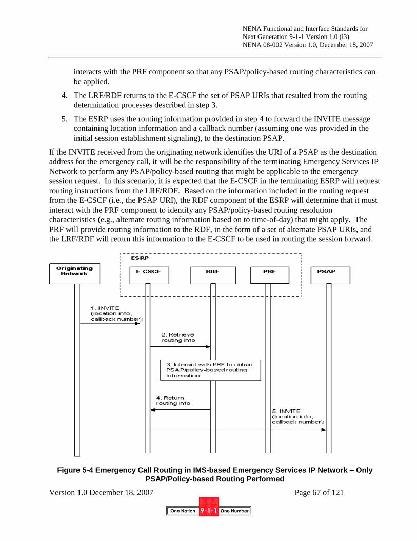
NENA Functional and Interface Standards for
Next Generation 9-1-1 Version 1.0 (i3)
NENA 08-002 Version 1.0, December 18, 2007
Version 1.0 December 18, 2007 Page 67 of 121
interacts with the PRF component so that any PSAP/policy-based routing characteristics can
be applied.
4. The LRF/RDF returns to the E-CSCF the set of PSAP URIs that resulted from the routing
determination processes described in step 3.
5. The ESRP uses the routing information provided in step 4 to forward the INVITE message
containing location information and a callback number (assuming one was provided in the
initial session establishment signaling), to the destination PSAP.
If the INVITE received from the originating network identifies the URI of a PSAP as the destination
address for the emergency call, it will be the responsibility of the terminating Emergency Services IP
Network to perform any PSAP/policy-based routing that might be applicable to the emergency
session request. In this scenario, it is expected that the E-CSCF in the terminating ESRP will request
routing instructions from the LRF/RDF. Based on the information included in the routing request
from the E-CSCF (i.e., the PSAP URI), the RDF component of the ESRP will determine that it must
interact with the PRF component to identify any PSAP/policy-based routing resolution
characteristics (e.g., alternate routing information based on to time-of-day) that might apply. The
PRF will provide routing information to the RDF, in the form of a set of alternate PSAP URIs, and
the LRF/RDF will return this information to the E-CSCF to be used in routing the session forward.
Figure 5-4 Emergency Call Routing in IMS-based Emergency Services IP Network – Only
PSAP/Policy-based Routing Performed

NENA Functional and Interface Standards for
Next Generation 9-1-1 Version 1.0 (i3)
NENA 08-002 Version 1.0, December 18, 2007
Version 1.0 December 18, 2007 Page 68 of 121
1. The originating network forwards the INVITE message containing location information, a
callback number (assuming one was provided in the initial session establishment signaling)
and a PSAP URI, to the Emergency Services IP Network that serves the PSAP identified by
the routing address.
2. To support PSAP/policy-based routing, the E-CSCF within the ESRP that receives the
emergency session request from the originating network queries an RDF for further routing
information.
3. The RDF determines that it must interact with the PRF that contains the attributes that will
drive the selection of the appropriate routing information based on a given set of conditions
for the specific PSAP identified in incoming signaling.
4. The routing information obtained by the RDF is returned to the E-CSCF.
5. The ESRP uses the routing information provided in step 4 to send the emergency session
request, in the form of an INVITE message containing location information and a callback
number (assuming one was provided in the initial session establishment signaling), to the
PSAP.
5.3 Call Release
PSAPs follow procedures in RFC3261[12] for call release. It is recommended that call origination
NOT terminate calls, following procedures in [59]. All proxies MUST add Vias. Via hiding MUST
NOT be permitted. Record-Route MUST be honored. TLS MUST be used within the Emergency
Services IP Network and SHOULD be used with entities outside it.
5.4 Relay calls
A caller may call a relay service, and have the service do a 3rd
party origination of a 9-1-1 call as
discussed in Section 5.7. Alternatively, a user may mark a call to 9-1-1 in such a way that the relay
service is automatically engaged. The latter avoids the step of first calling relay and having relay call
9-1-1; the call is established as a 3 way with the caller, the PSAP and the relay service in one step.
The PSAP upon receiving such a call:
1. ReInvites the caller to its bridge as per Section 5.6
2. Invites the appropriate relay service to its bridge. The PSAP MUST include the language and
preferred media of the original call.
5.5 Information Flows
This section illustrates information flows to support registration/deregistration, as well as signaling
and media connections in the originating network and the Emergency Services IP network to
implement various emergency services scenarios.

NENA Functional and Interface Standards for
Next Generation 9-1-1 Version 1.0 (i3)
NENA 08-002 Version 1.0, December 18, 2007
Version 1.0 December 18, 2007 Page 69 of 121
5.5.1 Registration/Deregistration Flow Examples
These flows assume that the PSAP is a “full” User Agent with all of the privileges and
responsibilities e.g. registering with an Authorization, Admission and Accounting (AAA) service.
5.5.1.1 Registration
As shown in Figure 5-5 PSAP UA Registration, PSAPs, as SIP User Agents, must register with the
network such that emergency calls may be delivered to them. As shown later, PSAPs may unregister
if they enter into night service or otherwise become unavailable. For a PSAP to register it sends a
registration request to an AAA server (Step A). In this sequence the AAA server challenges the
PSAP and the PSAP responds with its credentials. Once the PSAP is registered, the ESRP updates
the PSAP routing policy with the PRF (Step B). The PRF implements routing policy for the PSAP.
Figure 5-5 PSAP UA Registration
5.5.1.2 Deregistration
Figure 5-6 illustrates the scenario where the PSAP deregisters. This may be the case where the PSAP
is entering into night service or is otherwise unavailable. The PSAP sends a deregister message to the
ESRP. The ESRP forwards the deregistration to the AAA server and notifies the PRF.
Figure 5-6 Deregistration

NENA Functional and Interface Standards for
Next Generation 9-1-1 Version 1.0 (i3)
NENA 08-002 Version 1.0, December 18, 2007
Version 1.0 December 18, 2007 Page 70 of 121
5.5.1.3 Registration State Subscription
The PSAP may subscribe to its registration state. This is useful if there is a situation where the
network would need to inform the PSAP of an event where the PSAP must take some action. For
example, a network event may notify the PSAP to reregister. The PSAP subscribes to the ESRP (and
potentially to other elements such as the PRF). In the initial subscription, the network notifies the
PSAP of its state (available). Subsequent notifications may require action by the PSAP. Note that the
PSAP may use the subscription capability for other services or situations.
Figure 5-7 Registration State Subscription
5.5.2 IMS-based Call Flow Examples
This section illustrates information flows, as well as signaling and media connections in the
originating network and/or Emergency Services IP Network, to support emergency call/session
establishment under various emergency services scenarios. These flows use as a basis the functional
entities defined in Section 4.3.1, and the basic IMS-based 9-1-1 call setup procedures described in
Section 4.3.1.
These example flows assume a Back to Back User Agent (B2BUA), most likely in a Session Border
Controller, between the originating network and the Emergency Services IP Network. They also
assume that this B2BUA anchors the media channel. This removes the dependence upon the UA
implementing capabilities required by the ESInet, e.g. REFER. It also eliminates the need for the UA
to re-originate the call for features such as transfer and bridging. Such re-originations are subject to
congestion and blocking which may impact the feature. If the B2BUA did not anchor the media then
the signaling would pass through the B2BUA to the UA and the UA would be expected to execute
the request. Although common in IMS network implementations, it is recognized that the presence
of a B2BUA in an IMS network is not required.
5.5.2.1 Emergency Call Routing in an IMS-based Originating Network
Figure 5-8 illustrates the interactions between functional elements in an originating IMS network to
support emergency call routing. In Step A, the caller initiates an emergency session request which
the UE sends to a P-CSCF. Upon detecting the emergency session request, the P-CSCF selects an E-
CSCF and forwards the emergency session request to it. The E-CSCF recognizes the emergency
session request and interacts with an integrated LRF/RDF to determine how to route the call. In this

NENA Functional and Interface Standards for
Next Generation 9-1-1 Version 1.0 (i3)
NENA 08-002 Version 1.0, December 18, 2007
Version 1.0 December 18, 2007 Page 71 of 121
scenario, it is assumed that location information was delivered to the E-CSCF in the emergency
session request, and that this location information is sent to the LRF/RDF in the routing request. The
LRF/RDF interacts with an i3 ECRF which maps the location information (i.e., civic address or geo-
location) to a PSAP or ESRP URI. The LRF/RDF returns the primary address of the destination
PSAP or ESRP in the Emergency Services IP Network to the E-CSCF, along with any associated
alternate address information that may have been available in the ECRF. (The alternate address
information may be used by the E-CSCF to determine alternate handling in situations where the call
cannot be successfully delivered.) In Step B the E-CSCF forwards the session request signaling via a
Back to Back User Agent (B2BUA), most likely in a Session Border Controller, to an ESRP in the
Emergency Services IP Network.
Figure 5-8 Emergency Call Routing in an IMS Originating Network
5.5.2.2 Emergency Call Routing in an IMS Emergency Services IP Network
Three flows are provided below to illustrate the interaction of various functional entities within an
IMS Emergency Services IP Network under different routing scenarios. In the first scenario,
described in Section 5.5.2.2.1, the emergency session request received by IMS Emergency Services
IP Network contains an ESRP URI as the destination URI for the call, and the IMS Emergency
Services IP Network performs both location-based routing and PSAP/policy-based routing. This
would occur if the Emergency Services IP Network was the terminating network for the call. In the
second scenario, described in Section 5.5.2.2.2, the emergency session request received by the IMS
Emergency Services IP Network contains a PSAP URI as the destination URI for the call, and the
IMS Emergency Services IP Network performs PSAP/policy-based routing. This scenario would
also occur in an Emergency Services IP Network that was the terminating network for the call. In
the third scenario, the emergency session request received by the IMS Emergency Services IP
Network contains an ESRP URI as the destination URI, and the IMS Emergency Services IP
Network only performs location-based routing. This would occur if the Emergency Services IP
Network was one in a series of Emergency Services IP Networks in the path between the caller and
the PSAP, and it was not the terminating Emergency Services IP Network.
NENA Functional and Interface Standards for
Next Generation 9-1-1 Version 1.0 (i3)
NENA 08-002 Version 1.0, December 18, 2007
Version 1.0 December 18, 2007 Page 72 of 121
5.5.2.2.1 IMS Emergency Services IP Network Performs Location and Policy-based Routing
Figure 5-9 illustrates a scenario where the Emergency Services IP Network performs both location-
based and PSAP/policy-based routing. In Step A of this scenario, the originating network forwards
the session request signaling via the Session Border Controller (B2BUA) to the ESRP in the
Emergency Services IP Network. The emergency session request contains an ESRP URI as the
destination address, as well as caller location information. Upon receiving the emergency services
request, the E-CSCF component of the ESRP sends a request for routing information, to the
LRF/RDF functional component. In Step B, the LRF/RDF determines that location-based routing is
needed, and interacts with an i3 ECRF which does a civic to PSAP address or a geo to PSAP address
mapping and returns a set of location-based PSAP URIs to the LRF/RDF. Upon receiving the PSAP
URI information from the ECRF, the LRF/RDF determines that it must interact with the PRF
component of the ESRP. In Step C, the LRF/RDF interacts with the PRF to identify any
PSAP/policy-based routing resolution characteristics that might change the destination address that
should be used to route the call, and returns the address of the appropriate destination PSAP to the E-
CSCF, along with alternate PSAP addresses that may be used under different call scenarios (e.g.,
busy). In Step D, the ESRP signals the PSAP and session establishment messages are exchanged. In
Step E, the media sessions are completed between the Caller/Originating Network and PSAP A.

NENA Functional and Interface Standards for
Next Generation 9-1-1 Version 1.0 (i3)
NENA 08-002 Version 1.0, December 18, 2007
Version 1.0 December 18, 2007 Page 73 of 121
Figure 5-9 IMS Emergency Services IP Network Performs Location and Policy-based Routing
5.5.2.2.2 IMS Emergency Services IP Network Performs Policy-based Routing Only
Figure 5-10 illustrates a scenario where the Emergency Services IP Network only performs
PSAP/policy-based routing. This would occur in a scenario where the originating network
determined the address of the destination PSAP and included this information in the emergency
session request sent to the Emergency Services IP Network. In Step A of this scenario, the

NENA Functional and Interface Standards for
Next Generation 9-1-1 Version 1.0 (i3)
NENA 08-002 Version 1.0, December 18, 2007
Version 1.0 December 18, 2007 Page 74 of 121
originating network forwards the session request signaling via the Session Border Controller
(B2BUA) to the ESRP in the Emergency Services IP Network. The emergency session request
contains PSAP URI as the destination address. Upon receiving the emergency services request, the
E-CSCF functional component of the ESRP sends a request for routing information, to the LRF/RDF
functional component. In Step B, the LRF/RDF determines that only policy-based routing is needed,
and interacts with the PRF to identify any PSAP/policy-based routing resolution characteristics that
might change the destination address that should be used to route the call, and returns the address of
the appropriate destination PSAP to the E-CSCF, along with alternate PSAP addresses that may be
used under different call scenarios (e.g., busy). In Step C, the ESRP signals the PSAP and session
establishment messages are exchanged. In Step D, the media sessions are completed between the
Caller/Originating Network and PSAP A.
Figure 5-10 IMS Emergency Services IP Network Performs Policy-based Routing Only

NENA Functional and Interface Standards for
Next Generation 9-1-1 Version 1.0 (i3)
NENA 08-002 Version 1.0, December 18, 2007
Version 1.0 December 18, 2007 Page 75 of 121
5.5.2.2.3 IMS Emergency Services IP Network Performs Location-based Routing Only
As described in Section 5.5.2.2.1, if the emergency session request received by an Emergency
Services IP Network contains an ESRP URI as the destination address, the Emergency Services IP
Network will be expected to perform location-based routing. In Section 5.5.2.1, a scenario was
illustrated in which this location-based routing resulted in the identification of the destination PSAP
for the call. It is possible, in scenarios in which an emergency session request traverses multiple
Emergency Services IP Networks that the location-based routing performed in an Emergency
Services IP Network will result in the identification of an ESRP in a subsequent Emergency Services
IP Network. In this case, policy-based routing will not be performed, and the ESRP URI identified
as a result of location-based routing will be used to route the emergency session request forward.
Figure 5-11 illustrates this scenario. In Step A, the originating network forwards the session request
signaling via the Session Border Controller (B2BUA) to the ESRP in the Emergency Services IP
Network. The emergency session request contains an ESRP URI as the destination address, as well
as caller location information. Upon receiving the emergency services request, the E-CSCF
component of the ESRP sends a request for routing information, to the LRF/RDF functional
component. In Step B, the LRF/RDF determines that location-based routing is needed, and interacts
with an i3 ECRF which maps the civic address or geo-location to an ESRP URI and returns this
information to the RDF. Upon receiving the ESRP URI information from the ECRF, the LRF/RDF
determines that it should return this information to the E-CSCF component of the ESRP (without
interacting with a PRF), as illustrated in Step C. In Step D, the ESRP forwards the emergency
session request to an ESRP in a subsequent Emergency Services IP Network, where further location-
based routing is expected to be performed.

NENA Functional and Interface Standards for
Next Generation 9-1-1 Version 1.0 (i3)
NENA 08-002 Version 1.0, December 18, 2007
Version 1.0 December 18, 2007 Page 76 of 121
Figure 5-11 IMS Emergency Services IP Network Performs Location-based Routing Only
5.5.2.3 PSTN Call Origination presented to an IMS based Emergency Services IP Network
The scenario in Figure 5-12 illustrates a call originated from a legacy network. In this case the call
arrives at the PSTN Gateway with only the ANI (callback TN, ESRK, etc.). The PSTN GW interacts
with the LIS to obtain location information. The PSTN GW then queries the ECRF using the
location information obtained from the LIS, and obtains the address of the ESRP. In Step B, the call
is routed to the ESRP. The E-CSCF in the ESRP then interacts with the LRF/RDF, passing the
location information received from LIS to the LRF/RDF. In Step C, the LRF/RDF uses this
information to interact with the i3 ECRF. The i3 ECRF maps the location information to a PSAP
URI, and returns the PSAP URI back to the LRF/RDF. In Step D, the LRF/RDF uses the location-
based PSAP URI to interact with the PRF. The PRF will further resolve the destination PSAP URI
by applying any PSAP-specific routing logic/data that may be associated with the received PSAP
URI. The LRF/RDF then returns routing information, consisting of a destination PSAP URI and a
set of alternate PSAP URIs, to the E-CSCF. The ESRP signals the PSAP and the call set up
messages are exchanged (Step E). In Step F, the media sessions are completed between the Caller in
the PSTN and PSAP A.
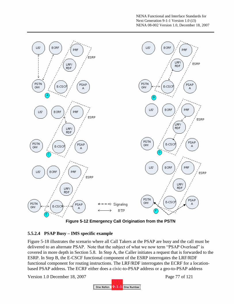
NENA Functional and Interface Standards for
Next Generation 9-1-1 Version 1.0 (i3)
NENA 08-002 Version 1.0, December 18, 2007
Version 1.0 December 18, 2007 Page 77 of 121
Figure 5-12 Emergency Call Origination from the PSTN
5.5.2.4 PSAP Busy – IMS specific example
Figure 5-18 illustrates the scenario where all Call Takers at the PSAP are busy and the call must be
delivered to an alternate PSAP. Note that the subject of what we now term “PSAP Overload” is
covered in more depth in Section 5.8. In Step A, the Caller initiates a request that is forwarded to the
ESRP. In Step B, the E-CSCF functional component of the ESRP interrogates the LRF/RDF
functional component for routing instructions. The LRF/RDF interrogates the ECRF for a location-
based PSAP address. The ECRF either does a civic-to-PSAP address or a geo-to-PSAP address

NENA Functional and Interface Standards for
Next Generation 9-1-1 Version 1.0 (i3)
NENA 08-002 Version 1.0, December 18, 2007
Version 1.0 December 18, 2007 Page 78 of 121
mapping, or and returns the address to the LRF/RDF. The LRF/RDF interacts with the PRF
functional component of the ESRP to check for any PSAP-based routing resolution characteristics
(e.g. should alternate routing be invoked) and returns routing instructions to the E-CSCF. Note that
in addition to the appropriate primary PSAP address the LRF/RDF returns alternate PSAP addresses.
In Step C, the ESRP signals the PSAP and the PSAP signals back busy indicating that all agents are
busy. The E-CSCF component of the ESRP invokes alternate call handling, and using the
appropriate alternate PSAP address obtained from the LRF/RDF, signals the alternate PSAP (PSAP
B), and the call set up messages are exchanged (Step D). In Step E the media sessions are completed
between the Caller in the PSTN and PSAP B.
A scenario can also be extrapolated where the PSAP is unreachable. In that scenario the ESRP
attempts to establish the call to the PSAP and a timer expires when PSAP A does not respond. The
ESRP then attempts the call to the alternate PSAP.
If the alternate PSAP is not available, the ESRP may iterate upon alternate PSAPs depending upon
how many were returned from the LRF/RDF. At some point the ESRP will take default routing
actions, which based upon local procedures may be to provide reorder or some other action.
This section illustrates information flows, as well as signaling and media connections in the
originating network and/or Emergency Services IP Network, to support emergency call/session
establishment under various emergency services scenarios. These flows use as a basis the functional
entities defined in Section 4.3.1, and the basic IMS-based 9-1-1 call setup procedures described in
Section 4.3.3.
These example flows assume a Back to Back User Agent (B2BUA), most likely in a Session Border
Controller, between the originating network and the Emergency Services IP Network. They also
assume that this B2BUA anchors the media channel. This removes the dependence upon the UA
implementing capabilities required by the ESInet, e.g. REFER. It also eliminates the need for the UA
to re-originate the call for features such as transfer and bridging. Such re-originations are subject to
congestion and blocking which may impact the feature. If the B2BUA did not anchor the media then
the signaling would pass through the B2BUA to the UA and the UA would be expected to execute
the request. Although common in IMS network implementations, it is recognized that the presence
of a B2BUA in an IMS network is not required.
5.5.2.5 Emergency Call Routing in an IMS-based Originating Network
Figure 5-13 illustrates the interactions between functional elements in an originating IMS network to
support emergency call routing. In Step A, the caller initiates an emergency session request which
the UE sends to a P-CSCF. Upon detecting the emergency session request, the P-CSCF selects an E-
CSCF and forwards the emergency session request to it. The E-CSCF recognizes the emergency
session request and interacts with an integrated LRF/RDF to determine how to route the call. In this
scenario, it is assumed that location information was delivered to the E-CSCF in the emergency
session request, and that this location information is sent to the LRF/RDF in the routing request. The
LRF/RDF interacts with an i3 ECRF which maps the location information (i.e., civic address or geo-
location) to a PSAP or ESRP URI. The LRF/RDF returns the primary address of the destination
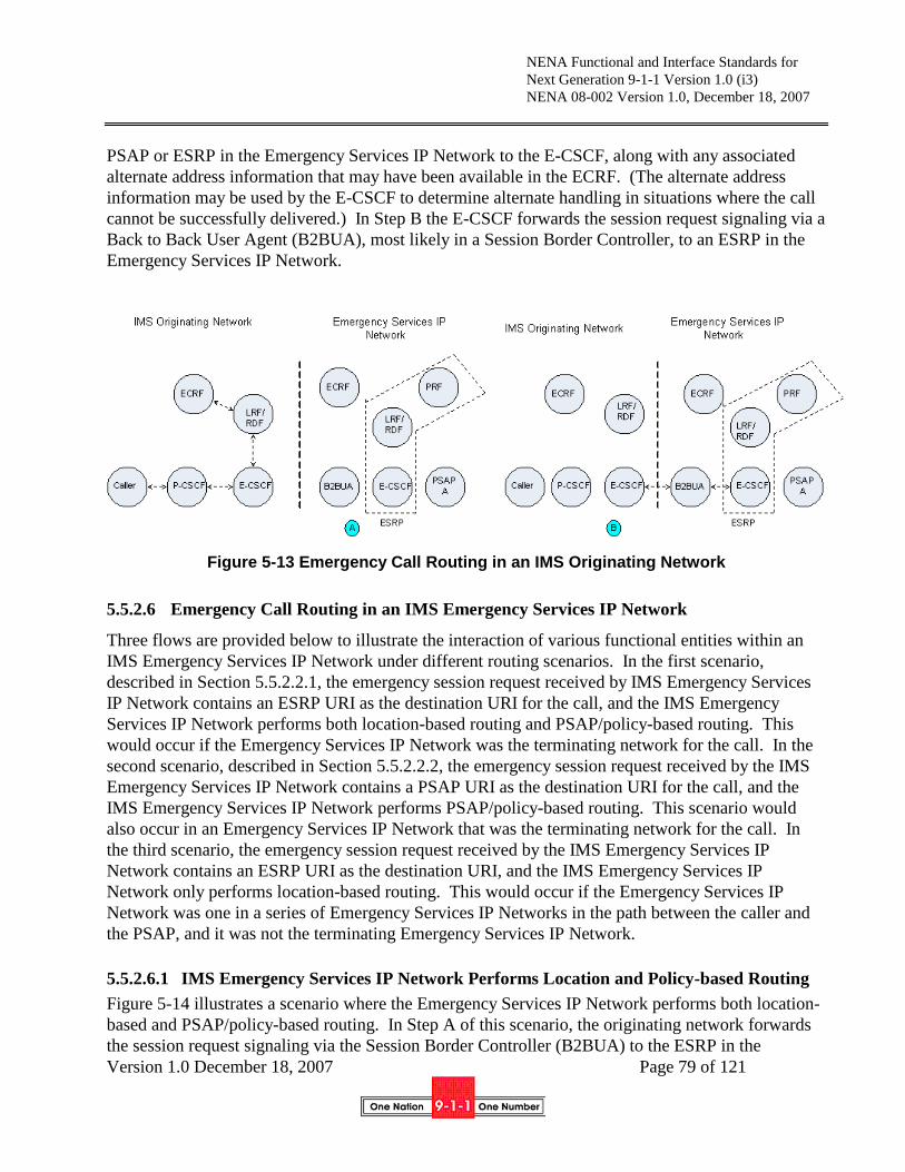
NENA Functional and Interface Standards for
Next Generation 9-1-1 Version 1.0 (i3)
NENA 08-002 Version 1.0, December 18, 2007
Version 1.0 December 18, 2007 Page 79 of 121
PSAP or ESRP in the Emergency Services IP Network to the E-CSCF, along with any associated
alternate address information that may have been available in the ECRF. (The alternate address
information may be used by the E-CSCF to determine alternate handling in situations where the call
cannot be successfully delivered.) In Step B the E-CSCF forwards the session request signaling via a
Back to Back User Agent (B2BUA), most likely in a Session Border Controller, to an ESRP in the
Emergency Services IP Network.
Figure 5-13 Emergency Call Routing in an IMS Originating Network
5.5.2.6 Emergency Call Routing in an IMS Emergency Services IP Network
Three flows are provided below to illustrate the interaction of various functional entities within an
IMS Emergency Services IP Network under different routing scenarios. In the first scenario,
described in Section 5.5.2.2.1, the emergency session request received by IMS Emergency Services
IP Network contains an ESRP URI as the destination URI for the call, and the IMS Emergency
Services IP Network performs both location-based routing and PSAP/policy-based routing. This
would occur if the Emergency Services IP Network was the terminating network for the call. In the
second scenario, described in Section 5.5.2.2.2, the emergency session request received by the IMS
Emergency Services IP Network contains a PSAP URI as the destination URI for the call, and the
IMS Emergency Services IP Network performs PSAP/policy-based routing. This scenario would
also occur in an Emergency Services IP Network that was the terminating network for the call. In
the third scenario, the emergency session request received by the IMS Emergency Services IP
Network contains an ESRP URI as the destination URI, and the IMS Emergency Services IP
Network only performs location-based routing. This would occur if the Emergency Services IP
Network was one in a series of Emergency Services IP Networks in the path between the caller and
the PSAP, and it was not the terminating Emergency Services IP Network.
5.5.2.6.1 IMS Emergency Services IP Network Performs Location and Policy-based Routing
Figure 5-14 illustrates a scenario where the Emergency Services IP Network performs both location-
based and PSAP/policy-based routing. In Step A of this scenario, the originating network forwards
the session request signaling via the Session Border Controller (B2BUA) to the ESRP in the

NENA Functional and Interface Standards for
Next Generation 9-1-1 Version 1.0 (i3)
NENA 08-002 Version 1.0, December 18, 2007
Version 1.0 December 18, 2007 Page 80 of 121
Emergency Services IP Network. The emergency session request contains an ESRP URI as the
destination address, as well as caller location information. Upon receiving the emergency services
request, the E-CSCF component of the ESRP sends a request for routing information, to the
LRF/RDF functional component. In Step B, the LRF/RDF determines that location-based routing is
needed, and interacts with an i3 ECRF which does a civic to PSAP address or a geo to PSAP address
mapping and returns a set of location-based PSAP URIs to the LRF/RDF. Upon receiving the PSAP
URI information from the ECRF, the LRF/RDF determines that it must interact with the PRF
component of the ESRP. In Step C, the LRF/RDF interacts with the PRF to identify any
PSAP/policy-based routing resolution characteristics that might change the destination address that
should be used to route the call, and returns the address of the appropriate destination PSAP to the E-
CSCF, along with alternate PSAP addresses that may be used under different call scenarios (e.g.,
busy). In Step D, the ESRP signals the PSAP and session establishment messages are exchanged. In
Step E, the media sessions are completed between the Caller/Originating Network and PSAP A.

NENA Functional and Interface Standards for
Next Generation 9-1-1 Version 1.0 (i3)
NENA 08-002 Version 1.0, December 18, 2007
Version 1.0 December 18, 2007 Page 81 of 121
Figure 5-14 IMS Emergency Services IP Network Performs Location and Policy-based
Routing
5.5.2.6.2 IMS Emergency Services IP Network Performs Policy-based Routing Only
Figure 5-15 illustrates a scenario where the Emergency Services IP Network only performs
PSAP/policy-based routing. This would occur in a scenario where the originating network
determined the address of the destination PSAP and included this information in the emergency
session request sent to the Emergency Services IP Network. In Step A of this scenario, the
originating network forwards the session request signaling via the Session Border Controller
(B2BUA) to the ESRP in the Emergency Services IP Network. The emergency session request
contains PSAP URI as the destination address. Upon receiving the emergency services request, the
E-CSCF functional component of the ESRP sends a request for routing information, to the LRF/RDF
functional component. In Step B, the LRF/RDF determines that only policy-based routing is needed,

NENA Functional and Interface Standards for
Next Generation 9-1-1 Version 1.0 (i3)
NENA 08-002 Version 1.0, December 18, 2007
Version 1.0 December 18, 2007 Page 82 of 121
and interacts with the PRF to identify any PSAP/policy-based routing resolution characteristics that
might change the destination address that should be used to route the call, and returns the address of
the appropriate destination PSAP to the E-CSCF, along with alternate PSAP addresses that may be
used under different call scenarios (e.g., busy). In Step C, the ESRP signals the PSAP and session
establishment messages are exchanged. In Step D, the media sessions are completed between the
Caller/Originating Network and PSAP A.
Figure 5-15 IMS Emergency Services IP Network Performs Policy-based Routing Only
5.5.2.6.3 IMS Emergency Services IP Network Performs Location-based Routing Only
As described in Section 5.5.2.2.1, if the emergency session request received by an Emergency
Services IP Network contains an ESRP URI as the destination address, the Emergency Services IP
Network will be expected to perform location-based routing. In Section 5.5.2.1, a scenario was
illustrated in which this location-based routing resulted in the identification of the destination PSAP
for the call. It is possible, in scenarios in which an emergency session request traverses multiple
Emergency Services IP Networks that the location-based routing performed in an Emergency

NENA Functional and Interface Standards for
Next Generation 9-1-1 Version 1.0 (i3)
NENA 08-002 Version 1.0, December 18, 2007
Version 1.0 December 18, 2007 Page 83 of 121
Services IP Network will result in the identification of an ESRP in a subsequent Emergency Services
IP Network. In this case, policy-based routing will not be performed, and the ESRP URI identified
as a result of location-based routing will be used to route the emergency session request forward.
Figure 5-16 illustrates this scenario. In Step A, the originating network forwards the session request
signaling via the Session Border Controller (B2BUA) to the ESRP in the Emergency Services IP
Network. The emergency session request contains an ESRP URI as the destination address, as well
as caller location information. Upon receiving the emergency services request, the E-CSCF
component of the ESRP sends a request for routing information, to the LRF/RDF functional
component. In Step B, the LRF/RDF determines that location-based routing is needed, and interacts
with an i3 ECRF which maps the civic address or geo-location to an ESRP URI and returns this
information to the RDF. Upon receiving the ESRP URI information from the ECRF, the LRF/RDF
determines that it should return this information to the E-CSCF component of the ESRP (without
interacting with a PRF), as illustrated in Step C. In Step D, the ESRP forwards the emergency
session request to an ESRP in a subsequent Emergency Services IP Network, where further location-
based routing is expected to be performed.
Figure 5-16 IMS Emergency Services IP Network Performs Location-based Routing Only

NENA Functional and Interface Standards for
Next Generation 9-1-1 Version 1.0 (i3)
NENA 08-002 Version 1.0, December 18, 2007
Version 1.0 December 18, 2007 Page 84 of 121
5.5.2.7 PSTN Call Origination presented to an IMS based Emergency Services IP Network
The scenario in Figure 5-17 illustrates a call originated from a legacy network. In this case the call
arrives at the PSTN Gateway with only the ANI (callback TN, ESRK, etc.). The PSTN GW interacts
with the LIS to obtain location information. The PSTN GW then queries the ECRF using the
location information obtained from the LIS, and obtains the address of the ESRP. In Step B, the call
is routed to the ESRP. The E-CSCF in the ESRP then interacts with the LRF/RDF, passing the
location information received from LIS to the LRF/RDF. In Step C, the LRF/RDF uses this
information to interact with the i3 ECRF. The i3 ECRF maps the location information to a PSAP
URI, and returns the PSAP URI back to the LRF/RDF. In Step D, the LRF/RDF uses the location-
based PSAP URI to interact with the PRF. The PRF will further resolve the destination PSAP URI
by applying any PSAP-specific routing logic/data that may be associated with the received PSAP
URI. The LRF/RDF then returns routing information, consisting of a destination PSAP URI and a
set of alternate PSAP URIs, to the E-CSCF. The ESRP signals the PSAP and the call set up
messages are exchanged (Step E). In Step F, the media sessions are completed between the Caller in
the PSTN and PSAP A.

NENA Functional and Interface Standards for
Next Generation 9-1-1 Version 1.0 (i3)
NENA 08-002 Version 1.0, December 18, 2007
Version 1.0 December 18, 2007 Page 85 of 121
Figure 5-17 Emergency Call Origination from the PSTN
5.5.2.8 PSAP Busy – IMS specific example
Figure 5-18 illustrates the scenario where all Call Takers at the PSAP are busy and the call must be
delivered to an alternate PSAP. Note that the subject of what we now term “PSAP Overload” is
covered in more depth in Section 5.8. In Step A, the Caller initiates a request that is forwarded to the
ESRP. In Step B, the E-CSCF functional component of the ESRP interrogates the LRF/RDF
functional component for routing instructions. The LRF/RDF interrogates the ECRF for a location-
based PSAP address. The ECRF either does a civic-to-PSAP address or a geo-to-PSAP address
mapping, or and returns the address to the LRF/RDF. The LRF/RDF interacts with the PRF
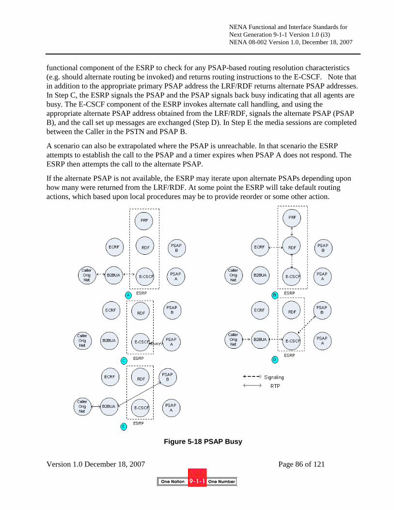
NENA Functional and Interface Standards for
Next Generation 9-1-1 Version 1.0 (i3)
NENA 08-002 Version 1.0, December 18, 2007
Version 1.0 December 18, 2007 Page 86 of 121
functional component of the ESRP to check for any PSAP-based routing resolution characteristics
(e.g. should alternate routing be invoked) and returns routing instructions to the E-CSCF. Note that
in addition to the appropriate primary PSAP address the LRF/RDF returns alternate PSAP addresses.
In Step C, the ESRP signals the PSAP and the PSAP signals back busy indicating that all agents are
busy. The E-CSCF component of the ESRP invokes alternate call handling, and using the
appropriate alternate PSAP address obtained from the LRF/RDF, signals the alternate PSAP (PSAP
B), and the call set up messages are exchanged (Step D). In Step E the media sessions are completed
between the Caller in the PSTN and PSAP B.
A scenario can also be extrapolated where the PSAP is unreachable. In that scenario the ESRP
attempts to establish the call to the PSAP and a timer expires when PSAP A does not respond. The
ESRP then attempts the call to the alternate PSAP.
If the alternate PSAP is not available, the ESRP may iterate upon alternate PSAPs depending upon
how many were returned from the LRF/RDF. At some point the ESRP will take default routing
actions, which based upon local procedures may be to provide reorder or some other action.
Figure 5-18 PSAP Busy

NENA Functional and Interface Standards for
Next Generation 9-1-1 Version 1.0 (i3)
NENA 08-002 Version 1.0, December 18, 2007
Version 1.0 December 18, 2007 Page 87 of 121
5.5.2.9 PSAP Unavailable for Service - IMS specific example
There may be situations where the primary PSAP is unavailable to take emergency calls. An example
is where the PSAP has night service closure. In this situation it is expected that the PSAP will
deregister as shown in Figure 5-6, instantiate a time-of-day based policy rule, or use a web services
interface to the PRF to dynamically change its policy. The ECRF may choose the primary PSAP (i.e.
PSAP A) but the PRF recognizes that it is not in service. In that case it will return an alternate PSAP
to the E-CSCF component of the ESRP via the RDF (e.g. PSAP B).
In Step A, the Caller initiates a request that is forwarded to the ESRP. In Step B, the E-CSCF
component of the ESRP interrogates the RDF for routing instructions and the RDF interrogates the
ECRF. The ECRF either does a civic-to-PSAP address or a geo-to-PSAP address mapping or returns
the PSAP address to the RDF. The RDF then interacts with the PRF component of the ESRP to
check the presence of PSAP A. The PRF determines that it is not registered (or has specified
alternate routes based on policy) and returns routing instructions for PSAP B (and potentially other
alternates) to the E-CSCF. In Step C, the ESRP signals PSAP B and the call set up messages are
exchanged. In Step D, the media sessions are completed between the Caller and PSAP B.
Figure 5-19 PSAP Unavailable for service

NENA Functional and Interface Standards for
Next Generation 9-1-1 Version 1.0 (i3)
NENA 08-002 Version 1.0, December 18, 2007
Version 1.0 December 18, 2007 Page 88 of 121
5.6 Bridging Another PSAP10
PSAPs have bridge services available, either inside the PSAP or via a service on the ESInet. Bridges
are SIP conference-based and provide multimedia bridging for all calls needing a bridge. A call may
be transferred to another PSAP or agency using the bridge either to give the call to appropriate
responders or to route the call to another PSAP due to a misroute. The originating PSAP could
either look the terminating PSAP/agency up in a directory if it knows the identity of the
PSAP/agency it wants, or it can query the (global) ECRF using the appropriate service with a
(possibly revised) location to determine the URI that will route to the correct PSAP/agency for the
location.
PSAPs may refer incoming calls to a bridge following procedures described in RFC 3515 [23]. The
bridge must conform to [51] and [52] and should implement [62] and [63]. Logging elements and
PSAP management monitoring functions may be anonymous participants. Normal policy of the
bridge should allow the conference to stay up when the PSAP that established the conference leaves.
Emergency calls bridged or transferred from a PSAP to another entity should follow identifier rules
in Section 5.1.5.
A high-level procedure for conference bridging in an IMS network is shown in Figure 5-20. In Step
A, the Emergency Caller and PSAP A are connected through the B2BUA and in conversation. In
Step B, PSAP A realizes the need to transfer (bridge) the Emergency Caller to PSAP B and seizes a
conference bridge. In the negotiation for the bridge, PSAP A receives a Conference ID that is to be
used by the other parties when they join the bridge. In Step C, PSAP A refers both the B2BUA and
PSAP B to the conference bridge. The SIP REFER message must contain the Location Object so that
PSAP B has the same information as PSAP A. In Step D, PSAP A and the B2BUA signal to join the
conference. In Step E, PSAP A, the B2BUA (and therefore the Caller) and PSAP B join the
conference bridge. If PSAP A completes its part of the activity and drops, the conference circuit may
not be released since the Caller and PSAP B are still in conversation.
10 In most cases bridging is initiated as part of a transfer operation from one PSAP to another.

NENA Functional and Interface Standards for
Next Generation 9-1-1 Version 1.0 (i3)
NENA 08-002 Version 1.0, December 18, 2007
Version 1.0 December 18, 2007 Page 89 of 121
Figure 5-20 PSAP Bridging
5.7 3rd party origination
Authorized entities may originate 3rd
party calls. The steps in creating a 3rd
party originated call are:
1, Caller places a normal SIP call to the 3rd
party
2. 3rd
party REFERs call to urn:service:sos, with a Referred-By set to an appropriate URI which a) is
within a domain authorized by the PSAP to originate 3rd
party calls and b) can link the original call
to the subsequent call from the PSAP bridge.
3. Caller‟s UA places call, as an emergency call to urn:service:sos following procedures described in
[59]. The call should retain the Referred-By header.
4. PSAP issues a Re-INVITE to its bridge.
5. PSAP requests its bridge to include the Referred-By URI in the conference by sending a REFER to
the 3rd party, with a Replaces header referencing the original call
6. The 3rd
party sends INVITE to the bridge to join the conference.
If a 3rd
party origination request is received by a PSAP where the Referred-By is NOT an authorized
entity, the PSAP may refuse to create a three party call, but accept the referred call as a two way
9-1-1 call between the PSAP and the original caller, or may choose to accept the call as a 3rd
party
origination.
Figure 5-21 illustrates the situation where the caller may not be able to re-originate an emergency
call. Such a situation exists in telematics applications where the mobile set does not have public
access. In Step A the caller originates a call and the 3rd
party call center and the mobile set may

NENA Functional and Interface Standards for
Next Generation 9-1-1 Version 1.0 (i3)
NENA 08-002 Version 1.0, December 18, 2007
Version 1.0 December 18, 2007 Page 90 of 121
exchange information to include the location of the caller. In Step B, the 3rd
party seizes its internal
conference bridge and initiates signaling to the Emergency Services Network. It may internally use
the ECRF capability being defined by i3 or some other means to determine the appropriate
terminating Emergency Services Network. In the signaling, the call center passes the location of the
Caller. In Step C the E-CSCF functional component of the ESRP interrogates the RDF component
for routing instructions. The RDF interrogates the ECRF for the PSAP URI. The ECRF returns the
URI to the RDF. The RDF interacts with the PRF functional component of the ESRP to check for
any PSAP-based routing resolution characteristics (e.g. should alternate routing be invoked) and
returns routing information to the E-CSCF. In Step D, the ESRP signals the PSAP and the call set up
messages are exchanged. In Step E the media sessions are completed among the Caller, the call
center and PSAP A.
Figure 5-21 3rd
Party Call using 3rd
Party’s Bridge
5.8 Overload (formerly Congestion Control)
What has historically been called “congestion control”, mechanisms embedded in the 9-1-1 network
to manage a large number of calls, evolves in an Emergency Services IP Network. The issues around
overload were explored in a joint NENA Technical Committee/Operations Committee Work Group,
which has produced a Technical Information Document[100] on the subject.

NENA Functional and Interface Standards for
Next Generation 9-1-1 Version 1.0 (i3)
NENA 08-002 Version 1.0, December 18, 2007
Version 1.0 December 18, 2007 Page 91 of 121
That work pointed out that in IP networks, the network itself can have much greater capacity to
handle more calls, but that if they were handled by the PSAP that served the area the caller was
located in, the number of calls would exceed the number of call takers, and thus not be useful.
Further, it observes that even with much greater capacity, all systems have limits, and the behavior of
all elements in an ESInet must be specified when such limits are exceeded. The TID observes that
the historic term “congestion control” inadequately described both the problems and approaches to
solving the problem in IP networks, and suggests two new terms:
PSAP Overload: The inability of an NG9-1-1 PSAP to answer all the calls that are being routed to it.
Element Overload: The inability of a specific element in an NG9-1-1 system to handle the load that
is being offered to it.
5.8.1 PSAP Overload
PSAP overload occurs in several distinct situations:
1. A local incident or incidents cause a temporary spike in the number of calls
2. A disaster occurs causing a very large number of calls, overwhelming both the PSAP and the
responders
3. A deliberate “Denial of Service” attack occurs on a PSAP, with a large number of bogus calls
directed to the PSAP
The TID observes that the classic network response of “busy” to the caller is an inadequate answer in
many circumstances. In the DoS case, good calls are mixed with the bad calls, and the good calls
must be answered. In the local spike case, although many calls are about the same incident,
providing no new information, there may be some calls from the same area which are not related to
the incident and need to be answered. Finally, in a disaster, calls must be answered and information
obtained to do a proper triaging of responders.
To be able to answer the calls when there are more calls than call takers, we must divert the calls to
another PSAP, and equip that PSAP with tools to provide information about the call back to the
PSAP where it should have been answered, and in some circumstances, provide callers with
information the original PSAP would have provided. Diversion is not the only possible response to
PSAP overload. Other choices include queuing for a call taker, Interactive Media Response (which
is like Interactive Voice Response, but handles audio, video and text media) and “busy”. Call
Treatment is the term we apply to these choices. The call treatment given to a caller depends on
PSAP state, and the policy of the PSAP in that state.
5.8.2 PSAP Overload Policy
PSAP management must be able to specify how calls directed to them will be handled. PSAP
management must be able to classify calls, discriminated by at least location, and possibly other
factors, PSAP condition (e.g. normal operation, major incident in process, disaster, deliberate attack,
etc), available call takers, state of network and local equipment, etc, and specify under those

NENA Functional and Interface Standards for
Next Generation 9-1-1 Version 1.0 (i3)
NENA 08-002 Version 1.0, December 18, 2007
Version 1.0 December 18, 2007 Page 92 of 121
conditions, which of multiple queues will receive a particular call, how large the queues are, and
what call treatment the call gets if the queue size is exceeded.
Call treatments must include, but are not limited to: Interactive Media Response, diversion to other
PSAPs, and busy.
Diversion of calls may happen in numerous places within the Emergency Services IP network. A
PSAP may divert calls that reach it, or some ESRP may detect a condition which would overflow the
PSAP, or the network connections to it. In the latter condition, the ESRP may divert, but only in
accordance with PSAP policy as above.
Calls must only be diverted to a PSAP which is willing to accept them. PSAP policy must govern
diversion of calls to it. Policy mechanisms must allow the receiving PSAP to control how many
calls can be diverted to it, and how its own calls are prioritized over diverted calls. Diverted calls
must be marked in such a way that the PSAP can discriminate between a call which was originally
routed to it and a call diverted by overflow from another PSAP.
SIP signaling of diverted calls would change the top Route header to the URI of the receiving PSAP,
and the addition of a History-Info header per RFC 4244[25]. It must be possible for the receiving
PSAP to identify the URI of the original target PSAP if the call must be transferred/bridged back to
it.
PSAPs receiving diverted calls must be able to access the Emergency Call Routing Function (ECRF)
that the original target PSAP would use in order to determine which responders would normally
handle responses to the call. Diverted calls may require the receiving PSAP to create entries in a
disaster database for use by such responders.
5.8.3 Element Overload
It may occur that an element within an ESInet receives more calls than it can handle; all systems
have limits and any part of the system may experience traffic greater than its limit. Typically, an
element would be considered in an Element Overload condition when the number of messages or
packets exceeded the capacity of the element or the network connections to it.
If the overloaded element knows that downstream elements have alternate paths, the congested
element may return a 503 Service Unavailable (or equivalent) error to signal its congestion
condition. Elements MUST NOT return 503 unless it is certain, by design and configuration that the
downstream element can reliably cope with the error. In all other conditions, the call should be
ended with a 600 Busy Everywhere error. The IETF is presently working on this problem and
defining a mechanism for overloaded elements to appropriately handle the condition [81].
Every element, including non SIP elements such as the ECRF must have mechanisms to detect
congestion it cannot reliably handle, report congestion state to the appropriate management systems,
and have adequate mechanisms for the overloaded element‟s clients to determine that it is
overloaded. Each client of such systems must have mechanisms to deal appropriately with overload
of any services it uses, which may include 600 Busy Everywhere.

NENA Functional and Interface Standards for
Next Generation 9-1-1 Version 1.0 (i3)
NENA 08-002 Version 1.0, December 18, 2007
Version 1.0 December 18, 2007 Page 93 of 121
5.8.4 Collecting and Disseminating Data from Diverted Callers
A call that is diverted to an alternate PSAP can be answered, and information obtained from the
caller, but that information must be given to the responders who can help the caller. This requires
the diversion PSAP to be able to enter information into the Computer Aided Dispatch system of
another PSAP. Traditional CAD systems have primitive data interfaces (typically just address data)
over even more primitive (typically serial port) interfaces. New interfaces must be made available to
accept much more rich data, with (controlled) access from diversion PSAPs. In addition, data
normally considered local to a PSAP, for example GIS data, validation data, and responder service
boundary data, must be made available to the diversion PSAP to be able to correctly complete a
CAD entry.
Note: The definition of the interface for a diversion PSAP to be able to enter data into the diverted
PSAP’s CAD must be undertaken as a joint effort with NENA and APCO (among others).
6 Service Creation
6.1 Defining a new service
A service is an abstract resource that represents a capability of performing tasks. To be used, a
service must be realized by a concrete service instance (service provider, provider entity).
A service interface (operations and messages) is the abstract boundary that a service exposes of the
underlying capability. These service interfaces are formally stated using the XML specification
language WSDL, each establishing a service contract of sorts. It is the content of this contract that
determines what is and is not abstracted.
Each service contract (WSDL) includes definitions for the following:
The abstract interface which defines the messages and messages exchange patterns
(operations) involved in interacting with the service
One or more concrete interfaces each of which defines a binding of the abstract interface.
Each binding specifies a specific protocol and data format that implements the abstract
interface.
One or more service end points (ports) each of which associates a concrete interface with a
URI that a service requester can use to interact with a service instance.
A service contract can be expressed as a single WSDL document or spread over a set of WSDL
documents using the native “import” mechanism defined in WSDL (as illustrated by the following
diagram).

NENA Functional and Interface Standards for
Next Generation 9-1-1 Version 1.0 (i3)
NENA 08-002 Version 1.0, December 18, 2007
Version 1.0 December 18, 2007 Page 94 of 121
Figure 6-1 Service Specification
Alternative combinations are also possible. For example if a service contract defines more that one
service end point, all service end points could each be defined in a WSDL document that imports a
common WSDL document containing the abstract and concrete specification definitions.
Additionally, message type definitions can be local or external to the abstract interface WSDL
document. In the latter case, a defining XML Schema document is referenced by specifying the
appropriate URI in a WSDL types import clause.
6.2 Service Registration and Discovery
Service discovery relies on the concept of a generally accessible service registry that hosts the
service definitions for all available services. Service discovery allows a potential service requester to
determine if a given serve exists and if so gain access to the corresponding service contract
information. Once a service requester has knowledge of a given service contract, it can interact with
an instance of that service.
6.2.1 Service Registration
The process of adding a service definition to the service registry is called service registration and is
usually performed by the service provider. Each registered service includes administrative (provider
identity) as well as technical (service contract) information about the service.
An ESInet will define normative service interfaces which multiple service entities will need to
support. Having service contracts spread over multiple WSDL documents, as described previously,
can greatly simplify management of such normative services. ESInet Administration is assigned the
responsibility of publishing the normative abstract and concrete interface specifications – somewhat
like pre-loading the service registry. Subsequently, service providers need only publish information
about their service end point(s), each of which references the appropriate already published interface
specifications.
UDDI (version 2 or higher) is the preferred service registry platform. UDDI registry entries are
registered through services provided by one or more UDDI Operator Nodes which make their
services available through well-known DNS address(es), normally a SOAP URI.

NENA Functional and Interface Standards for
Next Generation 9-1-1 Version 1.0 (i3)
NENA 08-002 Version 1.0, December 18, 2007
Version 1.0 December 18, 2007 Page 95 of 121
The OASIS - UDDI Spec TC manages the UDDI Specifications [72], Best Practices [73], and
Technical Notes [74].
6.2.2 Service Discovery
The service registry is in fact a database and as such, the process of finding a given service implies
formulating a query with appropriate search criteria values using a standardized API. Once the
service is found, one or more subsequent queries are used to retrieve service contract information.
UDDI queries can be issued at design/build time (through a web interface) or at run time (through an
API), depending on the type of application being developed. The most common usage scenario for
ESInet will be design/build time queries, especially for ESInet standard services. For such scenarios,
once service contract information is available, a portType is chosen and, if necessary a particular
binding, from which a stub or similar programming artifact is generated. In a run time scenario,
service implementations of a given portType and, optionally, binding are searched for to obtain the
service end-point URI.
6.3 Interacting with services
Interacting with a service instance implies that the service requester knows the service end point
URI. As described earlier, a service may expose its service interface through different bindings. For
each of these bindings, the service contract includes an end point definition which associates a URI
to a binding i.e. to a specific protocol and data format. In such cases, a service requester must first
decide which service end point it wishes to interact with.
Once an end point is determined, the service requester can interact with the service instance in
accordance with the associated protocol and data format. Service interactions are limited to those
message exchange patterns (MEPs) associated with the end point being used.
In most cases, the protocol connections underlying the service interactions will exist only for the
duration of a single service interaction.
Service interactions can be asynchronous (notification, solicit-response MEPs) or synchronous
(request-reply, one-way, fire-and-forget MEPs). Note that some concrete interfaces may not natively
support certain MEPs due to limitations of the underlying protocol.
6.4 Service Termination
As discussed in the previous section, binding protocol connections exist only for the duration of
service interactions. Consequently, a service requester can only know if a service end point is still
active through service interactions.
In ESInet, this may not be adequate for critical services as service requesters would like to become
aware of service failure or termination independently of the service interactions they initiate i.e. as
soon as the service becomes unavailable.

NENA Functional and Interface Standards for
Next Generation 9-1-1 Version 1.0 (i3)
NENA 08-002 Version 1.0, December 18, 2007
Version 1.0 December 18, 2007 Page 96 of 121
Although this can be achieved in various ways, ESInet defines a best practice (i.e. a preferred
approach) regarding service status awareness so that service requesters and providers deal with such
cases in consistent fashion.
The preferred approach builds on a notification MEP wherein a service requester receives
asynchronous “service up” status notifications at regular intervals. Service requester behavior then
interprets missing notifications as an indication of service failure. For this to work, a service
requester needs to explicitly tell the service provider which consumer-side end point URI to send
service status notifications. It does this through an appropriate provider-side interface; a form of
subscription to the service status notification feature.
If only critical services are subject to this, then “service terminating” notifications do not make
sense. Additionally, a service consumer does not need a way to cancel receiving service status
notifications. However, ESInet can define a best practice based on the above for general service
status notification that would include a cancelling mechanism.
7 Basic Services
7.1 Service Types
Text will be provided in a future edition of this standard.
7.2 Data associated with a call
Data associated with the call is provided in an xml data structure retrieved from a web service
operated by the origin network, or a contractor. The call includes a header with the URI of the web
service provided by the carrier routing proxy. The xml structure returned will be defined in future
work.
7.3 Data associated with a location
Data associated with a location is provided in an xml data structure retrieved from a web service.
The ECRF has an “additionalData” service (urn:service:sos.additionalData) which returns the URI
for the data associated with a location to authorized entities. The xml data structure returned will be
defined in future work.
7.4 Data associated with a caller
Data associated with a caller is provided in an xml data structure retrieved from a web service. The
call may include a header containing the URI for the data associated with the caller. The web service
may be operated by the carrier, or it may be operated by an independent service provider, who would
offer a URI for the data associated with the caller to every carrier the caller uses. The URI would be
part of the HSS (or equivalent user profile). The entity operating the domain MUST construct the
URI so that privacy of the caller is maintained. For example, the entity may provide each carrier, if
the caller has more than one carrier, with a different URI, any of which would return the same data.

NENA Functional and Interface Standards for
Next Generation 9-1-1 Version 1.0 (i3)
NENA 08-002 Version 1.0, December 18, 2007
Version 1.0 December 18, 2007 Page 97 of 121
The caller-data URI MUST only be provided automatically on emergency calls. The xml data
structure will be defined in future work.
7.5 Data associated with a PSAP
Text will be provided in a future edition of this standard.
7.6 Intra-Emergency Services IP Network Routing
Calls to other agencies within the Emergency Services IP network follow normal SIP (RFC3261)
routing mechanisms. Agencies on the ESInet MUST have a unique domain name and MUST
maintain an SRV entry in the DNS for the SIP server in their domain. Inter-agency calls with
addresses of the form “user@domain” consult the SRV entry in the DNS to determine the entry
proxy for the domain, which can be the terminal ESRP. All inter-ESInet calls MUST use TLS.
As discussed in Section 5.1, PSAPs make use of the ECRF to determine appropriate responders for
an emergency call based on the location of the caller. Where the location provided with the call is
not correct, but the call taker can determine the correct location, the ECRF can be queried by the
PSAP using the corrected location to determine responders.
One of the core services provided on the ESInet is a directory of agencies connected to the network.
Every agency MUST maintain an entry in the directory. The protocol for accessing the directory is
LDAP (RFC2251 [82]). LDAP implementation MUST use the LDAP TLS extension (RFC2830
[83])
7.7 Logging
A core service provided on the ESInet is a logging service. Any ESInet may have multiple instances
of logging services, but if there are multiple instances, each instance MUST have connections to the
core service. Every “significant” event occurring on the ESInet MUST be logged on the service. A
PSAP MAY provide an instance of a logging service. PSAPs may provide their own logging service
and may have different interfaces used internally. However, for multi-agency event reporting
purposes, the PSAP MUST support the standard external logging interface for retrieval of logged
events.
The WSDL of the logging service will be defined in future work. The primary operation of the
service, LogEvent logs an event according to the schema which will be defined in future work.
LogEvents include a timestamp, agency, agent (if appropriate), Call and Incident IDs (if appropriate)
and an EventType. Each EventType contains additional data specific to the EventType. A free-form
text string is also defined. LogEvent function assigns a globally unique LogIdentifier to each
LogEvent.
Media streams are recorded with the same log service; there are EventTypes for audio, video, text
and other media. Recorded media streams include integral time reference data within the stream.
Time stamps must be synchronized across all logging services.
NENA Functional and Interface Standards for
Next Generation 9-1-1 Version 1.0 (i3)
NENA 08-002 Version 1.0, December 18, 2007
Version 1.0 December 18, 2007 Page 98 of 121
Where multiple agencies are involved in a call or incident, they may log events in their own log
service related to that call/incident. Any agency who did not create the Call Identifier or Incident
Identifier (as appropriate) who logs events in their logging server against the call/incident MUST log
an “AdditionalAgency” event in the original agencies‟ log. This allows the original agency‟s log
service to be aware of any agencies that may have events relative to that call/incident.
For retrieval of logged events, core functions provided by the log service are:
ListEventsByCallId – which returns a list of LogEvents that have a specified Call Identifier
ListEventsByIncidentId – which returns a list of LogEvents that have a specified Incident
Identifier
ListCallsbyIncidentId – returns a list of Call Identifiers associated with a specific Incident
Identifier
List IncidentsByDateRange – returns a list of Incident Identifiers occurring with in a
time/date range
ListCallsByDateRange – returns a list of Call Identifiers occurring within a time/date range
ListAgenciesByCallId – returns a list of agencies who recorded AdditionalAgency events
about a call
ListAgenciesByIncidentId – returns a list of agencies who recorded AdditionalAgency events
about an Incident.
LogEvents are referenced by a URI, which would point back to the log server who maintains the log
of that event. Policy of the agency creating the LogEvents determines who can retrieve data about
such events.
For LogEvents that are media streams, the log service provides a playback service. The protocol for
the playback service is RTSP (RFC2326 [84]). The LogEvent for a media stream includes an RTSP
URI for the playback.
Each PSAP or other agencies that can create a Call Identifier or an Incident Identifier MUST provide
a LogServiceIdentifier service (WSDL to be defined) which implements the function
“MyLogService”. This function returns the identity of the logging service that serves that agency.
Given a Call Identifier or IncidentIdentifier, that would identify the agency that created the identifier,
the MyLogtService service would identify the logging service from which LogEvents about that Call
Identifier could be obtained.
8 Event Notification
ESInet stakeholders will exchange and share information following various interaction models, most
of which will involve a producer entity (source of the information) and one or more consumer
entities.

NENA Functional and Interface Standards for
Next Generation 9-1-1 Version 1.0 (i3)
NENA 08-002 Version 1.0, December 18, 2007
Version 1.0 December 18, 2007 Page 99 of 121
In cases where information is known to exist (e.g. a database) and is readily available to a producer,
consumers will request (pull) the information from the producer when they need it. The traditional
example is the ALI query. In other cases, the information a producer wishes to make available may
not be known or available in advance. One prevalent example is Amber Alerts. A more
accommodating interaction model is then required. For the purpose at hand, we will generically refer
to this model as event notification, where a producer will asynchronously push event information to
consumers as it becomes available. In this context, we will refer to a producer as a publisher.
Beyond the familiar emergency event of the emergency services domain, our use of the term event
also covers: changes in the internal state of resources, inter-agency advisories, process workflow
triggers, news feed items, weather, traffic and hazmat alerts and others. Moreover, some events may
be location-sensitive, meaning that their relevance to consumers depends on the geographic area in
which they occur.
The following are examples of event notifications:
1. Department of Homeland Security wants to be notified whenever certain types of incidents
occur so that they may trigger some specialized incident correlation process.
2. A PSAP wanting to receive Amber Alerts, but only those relevant to its jurisdiction (location-
sensitive event).
3. An Integrated Transportation System sending a closed road advisory to an Emergency
Operations Center.
4. A PSAP gets notified that a Computer Aided Dispatch system comes back into service.
Consumers opt-in to events. They specify which events they are interested in receiving and, in cases
of location-sensitive events, they specify the geographic area(s) of interest.
In the context of ESInet, event notification may affect public safety agencies beyond PSAPs, as well
as other agencies and entities. Even though it is recognized as a core feature of the ESInet, NENA
cannot, by itself, completely define the characteristics of specific service/application events.
However, since it is an ESInet objective to encourage interoperability amongst stakeholders, NENA
does include in this specification a set of recommendations and guidelines related to event
notification in order to secure some uniformity with ESInet.
8.1 Matching consumers with producers
Before a producer can start propagating event information to one or more consumers, it has to know
which consumers are interested in receiving such information. The way consumers communicate
their interest to publishers is through a subscription mechanism that is specific to the notification
technology in use. During subscription, the consumer expresses interest in specific events by way of
event topic lists and/or filter expressions.
Even though publishers will refuse a subscription request for unsupported event topics, large scale
systems, such as ESInet, that involve a potentially large numbers of publishers and a relatively large

NENA Functional and Interface Standards for
Next Generation 9-1-1 Version 1.0 (i3)
NENA 08-002 Version 1.0, December 18, 2007
Version 1.0 December 18, 2007 Page 100 of 121
set of different events, will provide registry-like core services that help event consumers find
appropriate publishers.
8.2 Event Topics Registry
An Event Topic Registry defines ESInet functional event topics. Each registry entry could include the
following properties:
1. Event Topic – the ESInet standard name for the event topic
2. Standard topic – Boolean (true for ESInet standardized topics, otherwise custom)
3. Reference to Event semantics – a document that describes what the event means, when it is
propagated… (textual)
4. Key words list – list of keywords that can complement registry queries
5. XML namespace URI of event information schema(s)
6. Policy statements about publisher and consumer relationships (textual)
7. URI list of children event topics (pointing to other registry entries)
The Event Topic Registry is meant to implement a namespace for ESInet-standard event topics,
which consumers can then leverage when looking for appropriate publishers (see Event Publisher
Registry below).
Management and access to this registry would be made available as an ESInet-defined core service
interface.
The event topics defined in the Registry are not only useful when matching consumer to publishers.
They can also be used during subscription establishment interactions when the consumer specifies
which event topics it is interested in. To accommodate application-specific event topics, many
notification technologies use the concept of dialect, which identifies the specificity of event topic
lists or filter expressions used in a particular subscription. An example of a dialect would be
XPath[96]. This also applies in cases where the notification technology includes “matched event
topics” metadata along with the application-specific event information returned to consumers.
8.3 Publisher Registry
This registry serves as a directory for all ESInet event publishers, possibly integrated with a more
comprehensive directory which includes agencies and services providers.
It is most likely that not all classes of ESInet events can be best served by a single notification
technology. Consequently a given publisher may appear more than once in the registry in cases
where the publisher supports multiple notification technology interfaces – each entry associated with
only one notification technology.
Each registry entry could include the following properties:
1. Publisher name/id
2. Publisher type (service, agency…)

NENA Functional and Interface Standards for
Next Generation 9-1-1 Version 1.0 (i3)
NENA 08-002 Version 1.0, December 18, 2007
Version 1.0 December 18, 2007 Page 101 of 121
3. Complementary publisher metadata (contact, credentials, UDDI ID, ..)
4. List of supported ESInet event topics (URIs as defined in the Event Topic Registry)
5. Technology identifier [WS-BasicNotification, WS-Eventing, SIP-SUBSCRIBE, RSS…]
6. End Point Reference (WS-Addressing) of notification/publisher service interface
7. Service Area, for publishers that serve location sensitive events
During registration, publishers specify which ESInet event topics they support, allowing consumers
to find matching publishers. The event topics are validated against the Event Topic Registry during
subscription.
Appropriate service interfaces will allow management/access to the Publisher Registry.
8.4 Event Notification Messages
Event notification messages differ from one notification technology to the next. Generally, these
messages serve as envelopes that wrap the application-specific event information and also
technology-specific notification metadata.
Most of the notification technologies can accommodate any application-specific event information in
the event notification message that is sent to consumers. Beyond their application-specific payload,
these messages often include event notification metadata (like matched event(s)).
For example, when using WS-BasicNotification, a Common Alerting Protocol (CAP)[97] event
could be packaged in the pre-defined Notify message (WS-BasicNotification does not force the use
of the pre-defined Notify message; it is there because it brings facilitating features to the consumer
end at the cost of a constraint on event topic dialects).
8.5 Advanced Event Notification mechanisms
In cases where there is a potentially large population of consumers, a publisher may want to sub-
contract subscription management to a separate entity – a notification broker.
In cases of high-volume events, the publisher might support the concept of a “pausable” subscription
– one that allows a consumer to toggle reception of events off/on as required.
For consumers with limited resources for example, a publisher might sub-contract the management
and operation of an event “pull site” i.e. one that accumulates notification messages and from which
the consumers can pull them at times of his own choosing.
8.6 Use case for location-sensitive events
An example of an event which is location sensitive might be notice of an impending tornado. The
“Tornado Warning” is the event topic. NOAA is (one of) the publisher(s) of this event. A PSAP
might subscribe to Tornado Warning events that affect its service area. In this system, events are
sent only to agencies who subscribe to the event topic, and only if the area affected by the event

NENA Functional and Interface Standards for
Next Generation 9-1-1 Version 1.0 (i3)
NENA 08-002 Version 1.0, December 18, 2007
Version 1.0 December 18, 2007 Page 102 of 121
includes at least a portion of the area the recipient agency serves. This means that alert notification
will in most cases be location based.
The location based routing mechanism could be the LoST server. For each registered event topic, a
service urn will be defined. An agency wishing to publish those events, will create a service
boundary in the LoST server covering their area of service (using mechanisms derived from similar
functions in the Emergency Provider Access Directory (EPAD)[98]). A subscribing entity can
determine the URI to subscribe by consulting the registry to determine which agency(s) publish that
topic in a given affected area. .
As an example, suppose there was a roll-over of a truck carrying a significant amount of hazmat
materials automatically detected by a “black box” in the truck. The PSAP at the crash site definitely
wants to know. Probably, the local emergency management agency, and the hazmat response team
(if it‟s not directly dispatched by the PSAP) may also wish to know.
An event topic for “Hazmat transport accident with high probability of spill” would be defined in the
event registry. The event information would include the location, truck and driver data, type and
quantity of hazmat material.
A shipper of Hazmat materials would register to publish this defined event topic and provide its
service area (perhaps a 12 state area) by placing an entry in the provider registry with the service
URN and the area that it serves. A PSAP could query the provider registry for this topic and its
service area. The PSAP would then Subscribe to the event.
When an incident occurred, the shipper would send the event to the PSAP. The body of the event
may have the event information described by the event definition. The event notification would be
received by the PSAP and it would take appropriate action.
9 Security
Every inter- and intra-Emergency Services IP Network communication should be protected by
appropriate security measures. Messages that directly relate to emergency services or databases
MUST be protected. TLS (RFC4346 [85]) should be used for all communications on the ESInet.
Where applications are certain that the entire path from sender to recipient is protected by equivalent
security means (for example, by IPSEC tunnels between a client and a server) then TLS may not be
needed. However, because it is difficult to determine whether an entire path is protected, TLS
should always be used. Perimeter security (walled gardens) should not be used as security measures
between entities on an ESInet. Mechanisms employing segregation of traffic (MPLS tunnels or
private IP address architectures for example) are not sufficient for protection and must not be relied
upon for secure communications.
NENA Functional and Interface Standards for
Next Generation 9-1-1 Version 1.0 (i3)
NENA 08-002 Version 1.0, December 18, 2007
Version 1.0 December 18, 2007 Page 103 of 121
9.1 Authentication
9.1.1 Authentication methods
PSAPs should implement strong authentication for their agents, employing two or three factor
(smartcards, passwords and/or biometrics). Simple password authentication alone should not be
relied upon for new services, but may be used with existing services. Such existing services may be
more susceptible to abuse because the interconnected ESInet may expose the interface to more
potential attackers. Password based authentication mechanisms shall protect the password such that
it is possible for the user to prove knowledge of the password without transmitting the password.
Unencrypted challenge/response exchanges may be captured by an eavesdropper, and the password
recovered offline. Thus any challenge/response mechanism must be encrypted.
9.1.2 SAML
Between agencies or between an agent/agency and a service, authentication in the Emergency
Services Network should use Security Assertion Markup Language, Version 2.0 (SAML 2.0 [86]).
PSAP identity should be federated to other services using SAML assertions. To the extent possible,
all services and facilities in the Emergency Services Network should provide “Single Sign On” using
SAML.
9.1.3 Credentials
A Public Key Infrastructure (PKI) for agencies on an Emergency Services Network will provide a
source of credentials for authentication. X.509 Public Key Certificates must be used for verifying
credentials. PSAPs and service providers will be issued credentials from the PSAP Credentialing
Agency (PCA). The PSAP PKI will provide a public key certificate to each PSAP and to service
providers providing services on one or more Emergency Services IP Networks. The agency or
service provider may then provide public key based credentials to each of its agents, signing the
credential with its PCA issued credential. The PCA shall seek cross certification with the Federal
Bridge Certificate Authority.
Private keys and other secrets maintained by a PSAP or other entity must be kept secure. [99]
contains advice for storing such sensitive material.
9.1.4 Certificate Policies
PSAPs and service providers issued certificates by the PCA must create certificate policies and
processes for maintaining credentials conformant with the PCA policy, the X.509 Certificate Policy
for the E-Governance Certification Authorities, and any applicable state or local government
certificate policies. Such policies MUST be consistent with the IETF Public Key Infrastructure
X.509 (PKIX), RFC3647 [87], Certificate Policy and Certification Practice Statement Framework.
NENA Functional and Interface Standards for
Next Generation 9-1-1 Version 1.0 (i3)
NENA 08-002 Version 1.0, December 18, 2007
Version 1.0 December 18, 2007 Page 104 of 121
9.1.5 Certificate Revocation Lists
The PCA and PSAPs and other service providers who issue credentials to their agents using a
certificate issued by the PCA must implement a Certificate Revocation List, and publish the CRL in
accordance with its Certificate Policy via both HTTP and LDAP protocols.
All certificates must be checked against the appropriate CRL before use.
9.1.6 Authentication using TLS
When using TLS for Authentication, RSA-1024 must be used. Normally, mutual authentication will
be used, but for some low security mechanisms, server authentication only may be sufficient.
9.1.7 Authentication using Web Services
Services that are implemented as web services should use SAML 2.0 Token Profile with Web
Security Services [WSS]. Web Services that create sessions with agents or agencies should use the
SAML Single Logout Profile to terminate the session.
9.1.8 Authentication using SIP
For SIP calls between entities (inter- or intra ESInet), SIP Identity [88] shall be used. To facilitate
use of SIP Identity, each ESInet shall provide at least one authentication service making use of the
credentials assigned by the PCA.
9.2 Authorization
For operations provided by services on the Emergency Services IP network, The SAML 2.0 Profile
of eXtensible Access Control Markup Language Version 2.0 (XACML 2.0 [89]) should be used to
control access. To facilitate use of XACML, each Emergency Services Network shall provide at
least one Policy Store conformant to XACML 2.0 using the LDAP profile for distribution of
XACML policies. Each service providing access control shall implement a Policy Enforcement
Point, and should retrieve policy from the ESInet‟s Policy Server.
XACML implementations should make use of the Core and hierarchical role based access control
(RBAC) profile of XACML v2.0. The following standard roles are defined for such use:
Call Taker – an agent of a PSAP who answers emergency calls
Call Taker Trainee – an agent of a PSAP who is learning to answer emergency calls
Call Taker Supervisor – an agent of a PSAP who supervises Call Takers
PSAP Manager – an agent of a PSAP who defines policy for a PSAP
Database Administrator – an agent of a 9-1-1 Authority who maintains address databases on
behalf of a set of PSAPs
Database Administrator Supervisor – an agent of a 9-1-1 Authority who supervises Database
Administrators

NENA Functional and Interface Standards for
Next Generation 9-1-1 Version 1.0 (i3)
NENA 08-002 Version 1.0, December 18, 2007
Version 1.0 December 18, 2007 Page 105 of 121
9-1-1 Authority Manager – an agent of a 9-1-1 Authority who defines policy for a PSAP.
9.3 Integrity Protection of messages
The standard method for integrity protection of messages in i3 is SHA-256 (in FIPS-PUB-180-2
[90]). There has been some concern raised whether SHA-1 is sufficiently robust against attack.
Existing systems employing SHA-1 need not be upgraded immediately. MD-5 hashes are not
sufficiently robust and must not be used.
9.4 Privacy
The standard method for privacy protection of messages in i3 is AES (FIPS-PUB-197 [91]). DES,
RC-4 or other weaker algorithms must not be used. Triple-DES should not be used, except for
existing services that cannot use AES.
9.5 Non-Repudiation
Security-sensitive actions taken within the network must be associated with an agent or agency in a
manner that provides non-repudiation by the responsible party. Such actions must be historically
traceable back to the responsible party in a manner that provides non-repudiation by the responsible
party of the accuracy of the historical information. The mechanism to accomplish such non-
repudiation should be a digital signature using an XML-Signature (RFC3275 [92]) with credentials
issued as per Section 9.1.3. Signed objects MAY be archived in the log service.
10 Service Management
Since many services external to a PSAP have significant influence in how a PSAP does its job,
providing effective management of such services in a consistent way is essential for PSAP
management. It is unrealistic for every service to provide completely consistent management
interfaces, but to the extent possible, new services must adhere to the following.
10.1 Provisioning
The i3 standard provisioning mechanism is Service Provisioning Markup Language, Version 2.0
(SPML 2.0 [93]). Each service provider on an Emergency Services IP network should supply an
SPML Provider. Each service would be at least one Target. The PSAP is expected to provide a
Requestor to provision Targets (services) it uses. Most Providers are expected to use the XSD
Profile. To the extent possible, common schemas should be established for services with
standardized interfaces. Each service defined by NENA must include a SPML schema to be used for
provisioning.
10.2 Remote Telecommunicator management
Text will be provided in a future edition of this standard.
NENA Functional and Interface Standards for
Next Generation 9-1-1 Version 1.0 (i3)
NENA 08-002 Version 1.0, December 18, 2007
Version 1.0 December 18, 2007 Page 106 of 121
10.3 Routing management
The route database for i3 is the LoST [61] mapping database. The standard mechanism to modify
the contents of the route database will be a web service whose WSDL will be defined in future work.
The interface will allow a 9-1-1 authority to search, get, insert, delete and modify its records in the
database.
It is recommended that the LoST mapping service not attempt to provide complex routing
mechanisms; rather it should only provide a primary and one or more alternate URIs for a given
service for a given requestor.
Requestor‟s should be grouped into classes:
User/Carrier queries: These queries normally return, or result in routing to an ESRP for all
services
ESRP-<Level>: These queries return URIs of a <Level-1> ESRP for all services. The lowest
level would be the entry proxy of a primary PSAP.
PSAP: These queries return URIs of responders for the requested service.
The 9-1-1 authority should be able to modify routes for all such classes.
The primary form of input data is a map, although optional tabular civic data can be used prior to
accurate maps being available. Civic locations are provided as points or polygons (parcels) or both.
Agency service boundaries are provided as sets of polygons. ESRP boundaries are also provided as
sets of polygons.
The resulting URI for a request should be capable of resolving in a more complex way; for example,
modifying the end PSAP may depend on time of day (shift), current congestion conditions, etc. This
would be accomplished within a PRF. This is resolution of a URI obtained from the LoST mapping
server.
10.4 Alarms
SNMP is the standard mechanism in i3 for reporting alarm conditions from network equipment
across the Emergency Services IP network. Simple Network Management Protocol (SNMPv3
RFC3410-RFC3418 [94]) must be used and the USM security module must be deployed. Identity
for SNMP requests should be federated with the Identity mechanism referred to in Section 9.1
The Alarm Web Service (which will be defined in future work) is the standard mechanism for
reporting alarms in web services on the ESInet.

NENA Functional and Interface Standards for
Next Generation 9-1-1 Version 1.0 (i3)
NENA 08-002 Version 1.0, December 18, 2007
Version 1.0 December 18, 2007 Page 107 of 121
10.5 Reports
10.5.1 Logging
A basic tenant of i3 external interfaces is that everything is logged in a consistent manner. Four
logging interfaces are defined:
A standardized external event log recorder used by all entities to log events. The recorder
includes media as discrete log entries (i.e. a file of media together with supporting data)
A standardized log retrieval tool that can be used to retrieved logged events from the log
A media logging recorder designed to create log events from real time media streams. The
media logger includes a client interface to the external event log recorder to enter external
event log entries in the log and a client for the log file transfer mechanism.
A file transfer mechanism used to upload large quantities of data to the logger
The external events log recorder and retriever are web services that use a generic log record.
Specific types of log events are then defined within the generic record format. The recorder and
retrieval tools can record any kind of event; even non-standard ones, so long as they conform to the
generic log record specification.
The generic log record includes:
A record ID, which is assigned by the logger. Each event is assigned a globally unique log ID
Timestamp
Source, which is a unique identifier for the entity supplying the log record
Call Id (if the event is associated with a specific call)
Incident Id (if the event is associated with a specific incident)
Record Type: the specific log record type, used to define the contents of the body of the event
record. The i3 specifications define some log record types; others may be defined by specific
implementations. A record type includes a unique identifier and an associated XML schema
The body of the record is an XML data structure defined by the record type schema. It may include a
reference to a file.
10.5.2 Quality Metrics
Text will be provided in a future edition of this standard.

NENA Functional and Interface Standards for
Next Generation 9-1-1 Version 1.0 (i3)
NENA 08-002 Version 1.0, December 18, 2007
Version 1.0 December 18, 2007 Page 108 of 121
10.5.2.1 VoIP quality metrics
All User Agents deployed within the Emergency Services IP network must support RTCP (RFC3550
[13]) as well as RTCP Extended Reports (RFC3611 [95]). User Agents should log RTCP reports for
calls, and PSAP systems should have collection and reporting mechanisms for these statistics.
Future versions of this specification will establish specific acceptable metrics for packet loss, burst
duration, jitter and observed quality for all media streams on an ESInet.
11 Roles and Responsibilities
11.1 Agencies
The entities responsible for the various functional elements include:
The access network operator
The calling network operator
A state emergency communications agency
A regional emergency communications agency. A regional emergency communications
agency is an entity that operates at the municipal, county, or multiple county level.
A 9-1-1 Authority (which may be the same as a state or regional emergency communications
agency
A PSAP
Not all areas will have state and/or regional emergency communications agencies with roles in Next
Generation 9-1-1. While defining ESInets as local to approximately a region, and interconnecting
region wide networks may be the ideal, in some jurisdictions, state wide networks will be the lowest
level division, and in others, a city will operate its own network. The following discussion describes
the ESInet as a 2 level hierarchy (region, state) but in a given jurisdiction, there may be fewer or
more levels. In addition, there may be national and/or international services provided on
interconnected ESInets, but this section does not allocate any responsibilities to such agencies.
Allocation of responsibility to the levels must be agreed to by the parties.
In addition, we define an “Emergency Services IP Network Operator” as being the entity that
manages the ESInet in a jurisdiction. In most cases, that will be a regional emergency
communications agency, but in others, it may be the state emergency communications agency or, in
some circumstances, a city agency.
Important Note: Any of the following responsibilities may be contracted by the responsible agency to
a commercial service provider or other government agency with specialized expertise analogous to
how the E9-1-1System Service Provider in many current 9-1-1 networks operates the Selective
Router and the ALI under contract to a 9-1-1 Authority. Indeed, it is expected that the majority of
the responsibilities for operating the Next Generation 9-1-1 functional elements to be contracted.
The text does not specifically identify the contractor in the following sections and no specific
grouping of functions that are expected to be contracted is provided.
NENA Functional and Interface Standards for
Next Generation 9-1-1 Version 1.0 (i3)
NENA 08-002 Version 1.0, December 18, 2007
Version 1.0 December 18, 2007 Page 109 of 121
11.2 Functional Element Responsible Agency
ESInet – in most cases a regional emergency communications agency operates a region wide public
safety network. These would be interconnected to form a state network. A state emergency
communications agency may operate a state-wide backbone network, and provide state-wide
monitoring and network management. State networks would be interconnected to form a national
network. Some federal agency may operate a national backbone network and provide nationwide
monitoring and network management.
LIS – The access network is responsible for providing the service and the data that it contains.
ECRF – 9-1-1 Authorities are responsible for the authoritative data for their jurisdiction in the
ECRF. The data may be aggregated at a regional or state level, and the actual server provided at that
level by a state or regional emergency communications agency. In addition, replicas of the ECRF
may be maintained by access or calling network operators.
LVF – 9-1-1 Authorities are responsible for the authoritative data for their jurisdiction in the LVF.
The data may be aggregated at a regional or state level, and the actual server provided at that level by
a state or regional emergency communications agency. In addition, replicas of the LVF may be
maintained by access or calling network operators.
Calling Proxy Server – The calling network operator is responsible for providing this function and
supplying 9-1-1 calls meeting this specification to the ESInet.
Top Level (ingress) ESRP (the ESRP on the edge of the Emergency Services IP network, to which
access networks, and the Internet, connect) – NENA recommends that a state level emergency
communications agency operate this ESRP, because the required bandwidth needed to withstand
massive denial of service attacks is likely to be provided most effectively and efficiently at the state
level, and this minimizes the number of physical connections access networks need to provide.
Intermediate ESRP (an ESRP in the middle of the ESInet) – These ESRPs are not required, but in
some cases regional network operators will desire to have an ESRP on entry to the regional network
and will operate same.
Terminating ESRP (an ESRP at the border of the PSAP) – The PSAP may operate an ESRP at the
edge of its local network to route calls to call takers.
Top Level (ingress) Border Control Function – The same entity that operates the top level ESRP,
most often a state emergency communications agency, operates a BCF before it.
Intermediate BCF may be placed in front of an intermediate ESRP if desired or may exist at the
regional network boundary even if the region does not operate an ESRP. The intermediate BCF
would be operated by the regional emergency communications agency.

NENA Functional and Interface Standards for
Next Generation 9-1-1 Version 1.0 (i3)
NENA 08-002 Version 1.0, December 18, 2007
Version 1.0 December 18, 2007 Page 110 of 121
Terminating BCF - NENA recommends that PSAPs operate BCFs at entry to the local PSAP
network, whether or not an ESRP is present. While the ESInet is a managed network and should
have controlled access, BCF functions between the ESInet and the PSAP is important.
Legacy Gateway – TBD
Core Services (Address Allocation, DNS, Services Broker, Policy Server, Network Monitoring and
Management) – The Emergency Services IP network operator provides core services. Some services
could be assigned to a state level ESInet operator even though the local ESInet operator is a regional
one.
Multimedia (Bridges, Loggers, Media Servers, etc. in the ESInet) – The Emergency Services IP
network operator provides multimedia services. Some services could be assigned to a state level
ESInet operator even though the local ESInet operator is a regional one
Supplemental Data – The ESInet operator is general responsible for all the services on the network.
In many cases, it is expected that supplemental data will be provided by a wide variety of agencies
and contractors. The ESInet operator would be responsible for approving and supervising the
connectivity and integration of the services into the network.
11.3 Summary of Agencies and other Entities Responsibilities
11.3.1 Access Network Operator
The access network operator is responsible for operating the LIS, providing location to endpoints
served by its network. The access network must validate location information (using the LVF)
placed in its LIS. Where the LIS supplies location references instead of, or in addition to, location
values, it must support dereferencing of the reference to a value for any entity in the ESInet (which
includes the PSAP and any ESRPs). The access network operator is also responsible to provide
access to an ECRF so that endpoints can learn routing and validate their locations.
11.3.2 Calling Network Operator
The calling network operator is responsible for operating the calling proxy server and delivering calls
to the BCF/ESRP in the ESInet. The calling network must convey the location of the endpoint to the
ESInet. Where endpoints provide dial string interpretation and routing functions, the calling network
is charged with routing the call based on the “PSAP URI” placed in the signaling by the endpoint.
Where the endpoints do not provide dial string interpretation and emergency call routing functions,
the calling network must supply such services. The calling network provides IP connectivity
(through direct trunking, virtual private network or Internet connections to the ESInet BCF). The
calling network provides call signaling connectivity (SIP/XMPP) to the ESRP.
It is recommended that if the calling network supports QoS for calls, that QoS should be maintained
all the way to the ESInet.
NENA Functional and Interface Standards for
Next Generation 9-1-1 Version 1.0 (i3)
NENA 08-002 Version 1.0, December 18, 2007
Version 1.0 December 18, 2007 Page 111 of 121
11.3.3 Regional Emergency Communications Agency
The regional emergency communications agency, in most jurisdictions, operates the regional or local
Emergency Services IP network, and provides the following services on it:
1. Core Services
2. Supplemental Data Services (but see the notes above on Supplemental Data Services)
3. Multimedia services
4. Intermediate Border Control Function
5. Intermediate Emergency Services Routing Proxy (where necessary)
6. Emergency Call Routing Function
The ECRF data is an aggregation of all 9-1-1 authority ECRF data in the region. The region is
responsible to arrange out of region referrals for its ECRF to other ECRFs in the state and to the state
wide ECRF for referrals out of state (or country).
The policy routing function in the regional ESRP an aggregation of local policies, overlaid with
region-wide policies. The regional agency is responsible for providing the mechanism to allow
PSAPs to instantiate its policy at the ESRP.
Regional agencies are responsible for arranging interconnect (IP) between their network and adjacent
county networks. This is both (redundant) physical connections and router configuration to allow
seamless interagency communications.
In most jurisdictions, the regional agency will have significant responsibilities to provide
credentialing to users of the network, although it may delegate to larger agencies that are capable of
providing their own credentialing.
11.3.4 State Emergency Communications Agency
The state emergency communications agency, in most jurisdictions, is responsible for operating the
interconnected Emergency Services IP network in the state (comprised of the regional networks
which are interconnected locally). The state agency may provide a backbone network to make
interconnection of local ESInets more efficient. The state should provide statewide network
monitoring and management functions. In addition, the state emergency communications agency
provides:
1. Top (ingress) Border Control Function
2. Top (ingress) Emergency Services Routing Proxy
The ECRF data comprises the merging of all local 9-1-1 authority data into a single server. The state
emergency communications agency is responsible assuring that references to locations out of state
from intra state queriers are correctly served, and for assuring that references to locations in state
from out of state queriers are correctly served.

NENA Functional and Interface Standards for
Next Generation 9-1-1 Version 1.0 (i3)
NENA 08-002 Version 1.0, December 18, 2007
Version 1.0 December 18, 2007 Page 112 of 121
The policy routing function in the ESRP is similarly an aggregation of local or regional (as
appropriate) policies, overlaid with state-wide policies. The state agency is responsible for providing
the mechanism to allow PSAPs (and/or regional agencies) to instantiate its policy at the ESRP.
State agencies are responsible for arranging interconnect (IP) between their network and adjacent
state networks. This is both (redundant) physical connections and router configuration to allow
seamless interagency communications.
11.3.5 9-1-1 Authority
The 9-1-1 authority is responsible for providing the data that comprises the ECRF and VF. It may
operate its own ECRF/VF. Any access network operator or other entity desiring a replica of the
ECRF/VF would arrange that service from the 9-1-1 authority. The 9-1-1 authority, together with its
PSAPs, is responsible for the policies in the state (and region, if provided) ESRPs that affect their
calls. The 9-1-1 authority issues credentials to agencies and individuals in its jurisdiction.
11.3.6 PSAP
The PSAP is responsible for providing the terminating ESRP and any internal versions of an ECRF
that it requires (beyond that provided by the 9-1-1 authority). It is responsible for accepting calls
routed to it by entry or intermediate ESRPs and transferring calls to secondary PSAPs. It is
responsible for creating the local policies that are used by ESRPs to route calls to it, and
communicating such policies to the appropriate ESRP(s).
12 Profiles and the minimal profile definition
Profiles bring added-value to systems interoperability. A profile will, for example:
provide guidelines and clarifications on how a related set of technologies and/or standards
specifications should be used together (ex: WS-I Basic Profile)
define specific subsets of system features/interfaces (ex: ESIF/TF34 EISI Profiles)
A profile may also include requirement statements. Conformance to a profile is defined as adherence
to the implicit or explicit requirements (mandatory, optional, conditional) within that profile. When
used in the context of conformance, profiles are then often known as conformance profiles.
Conformance profiles can reference other conformance profiles, possibly with additional constraints
-- a referenced optional requirement becomes mandatory for example.
Beyond their standalone value, conformance profiles can be referenced in system conformance
criteria which establish profile adherence expectations for system entities. One such conformance
statement could be: “All XYZ system entities SHALL behave in accordance with one or more of the
following conformance profiles: …”
In cases where conformance profiles are verifiable, they can then be referenced in a system entity‟s
conformance claim; stating adherence to the profile requirements.

NENA Functional and Interface Standards for
Next Generation 9-1-1 Version 1.0 (i3)
NENA 08-002 Version 1.0, December 18, 2007
Version 1.0 December 18, 2007 Page 113 of 121
Figure 12-1 Conformance Profiles
In i3, we define profiles on specific external interfaces and functional requirements. A physical box
or system claiming conformance to an i3 profile must implement all of the mandatory external
interfaces, may implement any optional interfaces. A conforming implementation will precisely, and
without exception implement all of the mandatory functions and external interface mechanisms
defined in the profile and may implement optional functions and interface mechanisms.
Conformance profiles will be defined for both sides of external interfaces and two conforming
implementations should interoperate when connected together. Within the box, or system, any i3
defined interfaces need not be implemented in order to claim compliance with the profile; only
interfaces external to the box or system need be implemented. For systems, this includes interfaces
between the physical components of the system, that is, if a system need not implement i3 defined
Conformance Profile
Mandatory Req.
Optional Req.
Conditional Req. Conformance
Profile
Conformance Claims
refs
refs
Conformance Profile
Mandatory Req.
Optional Req.
Conditional Req. Conformance
Profile
Conformance Claims
refs
refs
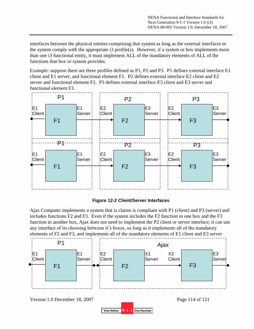
NENA Functional and Interface Standards for
Next Generation 9-1-1 Version 1.0 (i3)
NENA 08-002 Version 1.0, December 18, 2007
Version 1.0 December 18, 2007 Page 114 of 121
interfaces between the physical entities comprising that system as long as the external interfaces to
the system comply with the appropriate i3 profile(s). However, if a system or box implements more
than one i3 functional entity, it must implement ALL of the mandatory elements of ALL of the
functions that box or system provides.
Example: suppose there are three profiles defined as P1, P2 and P3. P1 defines external interface E1
client and E1 server, and functional element F1. P2 defines external interface E2 client and E2
server and functional element F2. P3 defines external interface E3 client and E3 server and
functional element F3.
Figure 12-2 Client/Server Interfaces
Ajax Computer implements a system that is claims is compliant with P1 (client) and P3 (server) and
includes functions F2 and F3. Even if the system includes the F2 function in one box and the F3
function in another box, Ajax does not need to implement the P2 client or server interface; it can use
any interface of its choosing between it‟s boxes, so long as it implements all of the mandatory
elements of F2 and F3, and implements all of the mandatory elements of E1 client and E3 server
F1 F2 F3
E1 Client
E1 Server
E2 Client
X1 Server
X2 Client
E3 Server
P1 Ajax
F1 F2 F3
E1 Client
E1 Server
E2 Client
E3 Server
E2 Client
E3 Server
P1 P2 P3
F1 F2 F3
E1 Client
E1 Server
E2 Client
E3 Server
E2 Client
E3 Server
P1 P2 P3

NENA Functional and Interface Standards for
Next Generation 9-1-1 Version 1.0 (i3)
NENA 08-002 Version 1.0, December 18, 2007
Version 1.0 December 18, 2007 Page 115 of 121
Figure 12-3 Combining services
Profiles are defined for common realizations expected in i3 implementations: ESRPs, LoST servers
(ECRF, LVF and Root Discovery Service), Firewall/Session Border Controller (BCF), Wireline
Gateway, Wireless Gateway, etc.
13 References
Note that this version of the document contains many references to documents which are work in
progress at the IETF and other organizations. As such this document may be revised as these
references stabilize.
[1] i3 Technical Requirements Document, National Emergency Number Association, NENA 08-751
[2] NENA Master Glossary of 9-1-1 Terminology, National Emergency Number Association,
NENA 00-001
[3] Interim VoIP Architecture for Enhanced 9-1-1 Services (i2), National Emergency Number
Association, NENA 08-001
[4] Framework for Emergency Calling in Internet Multimedia, B. Rosen, J. Polk, H. Schulzrinne, A.
Newton, Internet Engineering Task Force, draft-ietf-ecrit-framework
[5] Geopriv Requirements, J.Cueller et. Al, Internet Engineering Task Force, RFC 3693
[6] A Presence-based GEOPRIV Location Object Format, J. Peterson, Internet Engineering Task
Force, RFC 4119
[7] Dynamic Host Configuration Protocol Option for Coordinate-based Location Configuration
Information, J. Polk, J. Schnizlein, M. Linsner, Internet Engineering Task Force, RFC 3825
[8] Dynamic Host Configuration Protocol (DHCPv4 and DHCPv6) Option for Civic Addresses
Configuration Information, H. Schulzrinne, Internet Engineering Task Force, RFC 4776
[9] HTTP Enabled Location Delivery (HELD) M. Barnes, ed., Internet Engineering Task Force,
draft-ietf-geopriv-http-location-delivery
F1 F2 F3
E1 Client
E1 Server
E2 Client
X1 Server
X2 Client
E3 Server
P1 Ajax

NENA Functional and Interface Standards for
Next Generation 9-1-1 Version 1.0 (i3)
NENA 08-002 Version 1.0, December 18, 2007
Version 1.0 December 18, 2007 Page 116 of 121
[10] Session Initiation Protocol Location Conveyance, J. Polk, B. Rosen, Internet Engineering Task
Force, draft-ietf-sip-location-conveyance
[11] A Hitchhikers Guide to the Session Initiation Protocol (SIP), J. Rosenberg, Internet Engineering
Task Force, draft-ietf-sip-hitchhikers-guide
[12] Session Initiation Protocol, J, Rosenberg et. al., Internet Engineering Task Force, RFC 3261
[13] RTP: A Transport Protocol for Real-Time Applications, H. Schulzrinne et. al., Internet
Engineering Task Force, RFC 3550
[14] SDP: Session Description Protocol, J. Handley, V. Jacobson, Internet Engineering Task Force,
RFC 4566
[15] Session Initiation Protocol (SIP): Locating SIP Servers, J. Rosenberg, H. Schulzrinne, Internet
Engineering Task Force, RFC 3263
[16] An Offer/Answer Model with the Session Description Protocol (SDP), J. Rosenberg, H.
Schulzrinne, Internet Engineering Task Force, RFC 3264
[17] Session Initiation Protocol (SIP)-Specific Event Notification, A. Roach, Internet Engineering
Task Force, RFC 3265
[18] The Session Initiation Protocol UPDATE Method, J. Rosenberg, Internet Engineering Task
Force, RFC 3311
[19] A Privacy Mechanism for the Session Initiation Protocol (SIP), J. Peterson, RFC 3323
[20] Private Extensions to the Session Initiation Protocol (SIP) for Asserted Identity within Trusted
Networks, C. Jennings, J. Peterson, M. Watson, Internet Engineering Task Force, RFC 3325
[21] Session Initiation Protocol (SIP) Extension for Instant Messaging, B. Campbell et. al., Internet
Engineering Task Force, RFC 3428
[22] The Reason Header Field for the Session Initiation Protocol (SIP), H. Schulzrinne, D. Oran, G.
Camarillo, Internet Engineering Task Force, RFC 3326
[23] The Session Initiation Protocol (SIP) Refer Method, R. Sparks, Internet Engineering Task Force,
RFC 3515
[24] Grouping of Media Lines in the Session Description Protocol (SDP), G. Camarillo et. al.,
Internet Engineering Task Force, RFC 3388
[25] An Extension to the Session Initiation Protocol (SIP) for Symmetric Response Routing, J.
Rosenberg, H. Schulzrinne, Internet Engineering Task Force, RFC 3581
[26] Real Time Control Protocol (RTCP) attribute in Session Description Protocol (SDP), C.
Huitema, Internet Engineering Task Force, RFC 3605

NENA Functional and Interface Standards for
Next Generation 9-1-1 Version 1.0 (i3)
NENA 08-002 Version 1.0, December 18, 2007
Version 1.0 December 18, 2007 Page 117 of 121
[27] Control of Service Context using SIP Request-URI, B. Campbell, R. Sparks, Internet
Engineering Task Force, RFC 3087
[28] Connected Identity in the Session Initiation Protocol (SIP), J. Elwell, Internet Engineering Task
Force, RFC 4916
[29] Indicating User Agent Capabilities in the Session Initiation Protocol (SIP), J. Rosenberg, H.
Schulzrinne, P. Kyzivat, Internet Engineering Task Force, RFC 3840
[30] Caller Preferences for the Session Initiation Protocol (SIP), J. Rosenberg, H. Schulzrinne, P.
Kyzivat, Internet Engineering Task Force, RFC 3841
[31] A Presence Event Package for the Session Initiation Protocol (SIP), J. Rosenberg, Internet
Engineering Task Force, RFC 3856
[32] A Watcher Information Event Template-Package for the Session Initiation Protocol (SIP), J.
Rosenberg, Internet Engineering Task Force, RFC 3857
[33] The Session Initiation Protocol (SIP) "Replaces" Header, R. Mahy, B. Biggs, R. Dean, Internet
Engineering Task Force, RFC 3891
[34] The Session Initiation Protocol (SIP) Referred-By Mechanism, R. Sparks, Internet Engineering
Task Force, RFC 3892
[35] Best Current Practices for Third Party Call Control (3pcc) in the Session Initiation Protocol
(SIP), J. Rosenberg et. al., Internet Engineering Task Force, RFC 3725
[36] Using E.164 numbers with the Session Initiation Protocol (SIP), J. Peterson et. al., Internet
Engineering Task Force, RFC 3824
[37] Early Media and Ringing Tone Generation in the Session Initiation Protocol (SIP), G.
Camarillo, H. Schulzrinne, Internet Engineering Task Force, RFC 3960
[38] Presence Information Data Format (PIDF), H. Sugano, Internet Engineering Task Force, RFC
3863
[39] Session Timers in the Session Initiation Protocol (SIP), S. Donovan, J. Rosenberg, Internet
Engineering Task Force, RFC 4028
[40] Internet Media Type message/sipfrag, R. Sparks, Internet Engineering Task Force, RFC 3420
[41] The Session Initiation Protocol (SIP) "Join" Header, R. Mahy, D. Petrie, Internet Engineering
Task Force, RFC 3911
[42] Transcoding Services Invocation in the Session Initiation Protocol (SIP) Using Third Party Call
Control (3pcc), G. Camarillo et. al., Internet Engineering Task Force, RFC 4117
[43] Basic Network Media Services with SIP, J. Berger et. al., Internet Engineering Task Force, RFC
4240
NENA Functional and Interface Standards for
Next Generation 9-1-1 Version 1.0 (i3)
NENA 08-002 Version 1.0, December 18, 2007
Version 1.0 December 18, 2007 Page 118 of 121
[44] An Extension to the Session Initiation Protocol (SIP) for Request History Information, M.
Barnes et. al., Internet Engineering Task Force, RFC 4244
[45] Actions Addressing Identified Issues with the Session Initiation Protocol's (SIP) Non-INVITE
Transaction, R. Sparks, Internet Engineering Task Force, RFC 4320
[46] Extending the Session Initiation Protocol (SIP) Reason Header for Preemption Events, J. Polk,
Internet Engineering Task Force, RFC 4411
[47] Communications Resource Priority for the Session Initiation Protocol (SIP), H. Schulzrinne, J.
Polk, Internet Engineering Task Force, RFC 4412
[48] Suppression of Session Initiation Protocol (SIP) REFER Method Implicit Subscription, O.
Levin, Internet Engineering Task Force, RFC 4488
[49] Conveying Feature Tags with the Session Initiation Protocol (SIP) REFER Method, O. Levin, A.
Johnston, Internet Engineering Task Force, RFC 4508
[50] Addressing an Amplification Vulnerability in Session Initiation Protocol (SIP) Forking Proxies,
R. Sparks et. al., draft-ietf-sip-fork-loop-fix
[51] Session Initiation Protocol Call Control - Conferencing for User Agents, A. Johnston, O. Levin,
Internet Engineering Task Force, RFC4579
[52] A Session Initiation Protocol (SIP) Event Package for Conference State, R. Rosenberg, H.
Schulzrinne, O. Levin, Internet Engineering Task Force, RFC 4579
[53] Obtaining and Using Globally Routable User Agent (UA) URIs (GRUU) in the Session
Initiation Protocol (SIP), J. Rosenberg, Internet Engineering Task Force, draft-ietf-sip-gruu
[54] Managing Client Initiated Connections in the Session Initiation Protocol (SIP), C. Jennings et.
al., Internet Engineering Task Force, draft-ietf-sip-outbound
[55] SDP: Session Description Protocol, M. Handley et. al, Internet Engineering Task Force, RFC
4566
[56] Session Initiation Protocol Package for Voice Quality Reporting Event, A. Pendleton et. al.,
Internet Engineering Task Force, draft-ietf-sipping-rtcp-summary
[57] Interactive Connectivity Establishment (ICE): A Methodology for Network Address Translator
(NAT) Traversal for Offer/Answer Protocols, J. Rosenberg, Internet Engineering Task Force,
draft-ietf-mmusic-ice
[58] A Uniform Resource Name (URN) for Services, H. Schulzrinne, Internet Engineering Task
Force, draft-ietf-ecrit-service-urn
[59] Best Current Practice for Communications Services in support of Emergency Calling, B. Rosen,
J. Polk, Internet Engineering Task Force, draft-ietf-ecrit-phonebcp

NENA Functional and Interface Standards for
Next Generation 9-1-1 Version 1.0 (i3)
NENA 08-002 Version 1.0, December 18, 2007
Version 1.0 December 18, 2007 Page 119 of 121
[60] Location-to-URL Mapping Architecture and Framework, H. Schulzrinne, Internet Engineering
Task Force, draft-ietf-ecrit-mapping-arch
[61] LoST: A Location-to-Service Translation Protocol, T. Hardie et. al., Internet Engineering Task
Force, draft-ietf-ecrit-lost
[62] A Framework for Centralized Conferencing, M. Barnes, C. Boulton, O. Levin, Internet
Engineering Task Force, draft-ietf-xcon-framework
[63] Conference Information Data Model for Centralized Conferencing (XCON), O. Novo, G.
Camarillo, D. Morgan, E. Even, Internet Engineering Task Force, draft-ietf-xcon-common-
data-model
[64] IP Multimedia Subsystem (IMS) emergency sessions, 3rd
Generation Partnership Project, 3GPP
TS 23.167
[65] General Packet Radio Service (GPRS); Service description; Stage 2, 3rd
Generation Partnership
Project, 3GPP TS 23.060
[66] IP Multimedia Subsystem (IMS); Stage 2, 3rd
Generation Partnership Project, 3GPP TS 23.228
[67] ATIS Next Generation Network (NGN) Framework, Part III: Standards Gap Analysis, Alliance
for Telecommunications Industry Solutions, May 2006
[68] IP Network-to-Network Interface (NNI) Standard for VoIP, Alliance for Telecommunications
Industry Solutions, ATIS-PP-1000009.2006
[69] Emergency Services Messaging Interface (ESMI), Alliance for Telecommunications Industry
Solutions, ATIS-PP-0500002-200X
[70] Emergency Services Network Interfaces (ESNI) Framework, Alliance for Telecommunications
Industry Solutions, ATIS-0500008
[71] Enhanced Wireless 9-1-1 Phase 2, Telecommunications Industry Association and Alliance for
Telecommunications Industry Solutions, J-STD-036-B
[72] Universal Description, Discovery and Integration (UDDI) Version 3.0, Organization for the
Advancement of Structured Information Standards (OASIS), UDDI V3.0
[73] OASIS UDDI Specifications TC - Committee Best Practices, Organization for the Advancement
of Structured Information Standards (OASIS), UDDI Best Practices
[74] OASIS UDDI Specifications TC - Committee Technical Notes, Organization for the
Advancement of Structured Information Standards (OASIS), UDDI Technical Notes
[75] NENA Technical Requirements Document for Location Information to Support IP-Based
Emergency Services, NENA 08-752, Issue 1
[76] NENA Recommended Method(s) for Location Determination to Support IP-Based Emergency
Services - Technical Information Document, NENA 08-505, Issue 1

NENA Functional and Interface Standards for
Next Generation 9-1-1 Version 1.0 (i3)
NENA 08-002 Version 1.0, December 18, 2007
Version 1.0 December 18, 2007 Page 120 of 121
[77] GEOPRIV PIDF-LO Usage Clarification, Considerations and Recommendations, J.
Winterbotton, M. Thomson, H. Tschofenig, Internet Engineering Task Force, draft-ietf-geopriv-
pdif-lo-profile
[78] Revised Civic Location Format for PIDF-LO, M. Thomson, J. Winterbottom, Internet
Engineering Task Force, draft-ietf-geopriv-revised-civic-lo
[79] Requirements for a Location-by-Reference Mechanism used in Location Configuration and
Conveyance, R. Marshall, Internet Engineering Task Force, draft-marshall-geopriv-lbyr-
requirements
[80] Using HELD as a Location URI Dereference Protocol, J. Winterbottom, M. Thomson, M.
Dawson, Internet Engineering Task Force, draft-winterbottom-geopriv-held-deref-bcp
[81] Session Initiation Protocol (SIP) Overload Control, V. Hilt, D. Malas, H. Schulzrinne, Internet
Engineering Task Force, draft-hilt-sipping-overload
[82] Lightweight Directory Access Protocol (v3), M. Wahl, T. Howes, S. Kille, Internet Engineering
Task Force, RFC2251
[83] Lightweight Directory Access Protocol (v3) Extension for Transport Layer Security, J. Hodges,
R. Morgan, M. Wahl, Internet Engineering Task Force, RFC2830
[84] Real Time Streaming Protocol (RTSP), H. Schulzrinne, A. Rao, M. Lanphier, Internet
Engineering Task Force, RFC2326
[85] The Transport Layer Security (TLS) Protocol Version 1.1, T. Dierks, E. Rescola, Internet
Engineering Task Force, RFC4346
[86] Assertions and Protocols for the OASIS Security Assertion Markup Language (SAML) V2.0,
Organization for the Advancement of Structured Information Standards (OASIS), saml-core-2.0-
os
[87] Internet X.509 Public Key Infrastructure Certificate Policy and Certification Practices
Framework, S. Chokani et. al., Internet Engineering Task Force, RFC3647
[88] Enhancements for Authenticated Identity Management in the Session Initiation Protocol (SIP), J.
Peterson, C. Jennings, Internet Engineering Task Force, RFC4474
[89] eXtensible Access Control Markup Language (XACML) Version 2.0, Organization for the
Advancement of Structured Information Standards (OASIS), XACML 2.0
[90] The Secure Hash Algorithm, Federal Information Processing Standards Publication 180-2,
National Institute of Standards and Technology, FIPS-PUB-180-2
[91] Advanced Encryption Standard, Federal Information Processing Standards Publication 197,
National Institute of Standards and Technology, FIPS-PUB-197
[92] (Extensible Markup Language) XML-Signature Syntax and Processing, D. Eastlake, J. Reagle,
D. Solo, Internet Engineering Task Force, RFC3275

NENA Functional and Interface Standards for
Next Generation 9-1-1 Version 1.0 (i3)
NENA 08-002 Version 1.0, December 18, 2007
Version 1.0 December 18, 2007 Page 121 of 121
[93] OASIS Service Provisioning Markup Language (SPML) Version 2, Organization for the
Advancement of Structured Information Standards (OASIS), pstc-spml-2.0-os
[94] Simple Network Management Protocol, Version 3 (SNMPv3), J. Case, et. al., Internet
Engineering Task Force, RFC3410 through RFC3418
[95] RTP Control Protocol Extended Reports (RTCP XR), T. Friedman ed., Internet Engineering
Task Force. RFC3611
[96] XML Path Language (XPath) Version 1.0, J. Clark, S. Derose, World Wide Web Consortium
(W3C), TR/1999/REC-xpath-19991116
[97] Common Alerting Protocol V1.0, A. Botterell, Organization for the Advancement of Structured
Information Standards (OASIS), oasis-200402-cap-core-1.0
[98] Emergency Provider Access Directory (EPAD) Technical Implementation Guide, J. Rowland, J.
Lawton, COMCARE, EPAD TIG
[99] Security Requirements for Cryptographic Modules, Federal Information Processing Standards
Publication 140-3, National Institute of Standards and Technology, FIPS-PUB-140-3
[100] Report from the Special Joint LTD/PONGI Tech/Ops team on Congestion Control in
NG9-1-1 Technical Information Document, National Emergency Number Association, work in
progress


