
Network Layer and Data Center Topologies
Hakim WeatherspoonAssistant Professor, Dept of Computer Science
CS 5413: High Performance Systems and NetworkingSeptember 8, 2014
Slides used and adapted judiciously from Computer Networking, A Top-Down Approach

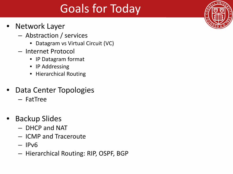
Goals for Today• Network Layer
– Abstraction / services• Datagram vs Virtual Circuit (VC)
– Internet Protocol• IP Datagram format• IP Addressing• Hierarchical Routing
• Data Center Topologies– FatTree
• Backup Slides– DHCP and NAT– ICMP and Traceroute– IPv6– Hierarchical Routing: RIP, OSPF, BGP

transport segment from sending to receiving host
on sending side encapsulates segments into datagrams
on receiving side, delivers segments to transport layer
network layer protocols in every host, router
router examines header fields in all IP datagrams passing through it
applicationtransportnetworkdata linkphysical
applicationtransportnetworkdata linkphysical
networkdata linkphysical network
data linkphysical
networkdata linkphysical
networkdata linkphysical
networkdata linkphysical
networkdata linkphysical
networkdata linkphysical
networkdata linkphysical
networkdata linkphysical
networkdata linkphysicalnetwork
data linkphysical
Network Layer

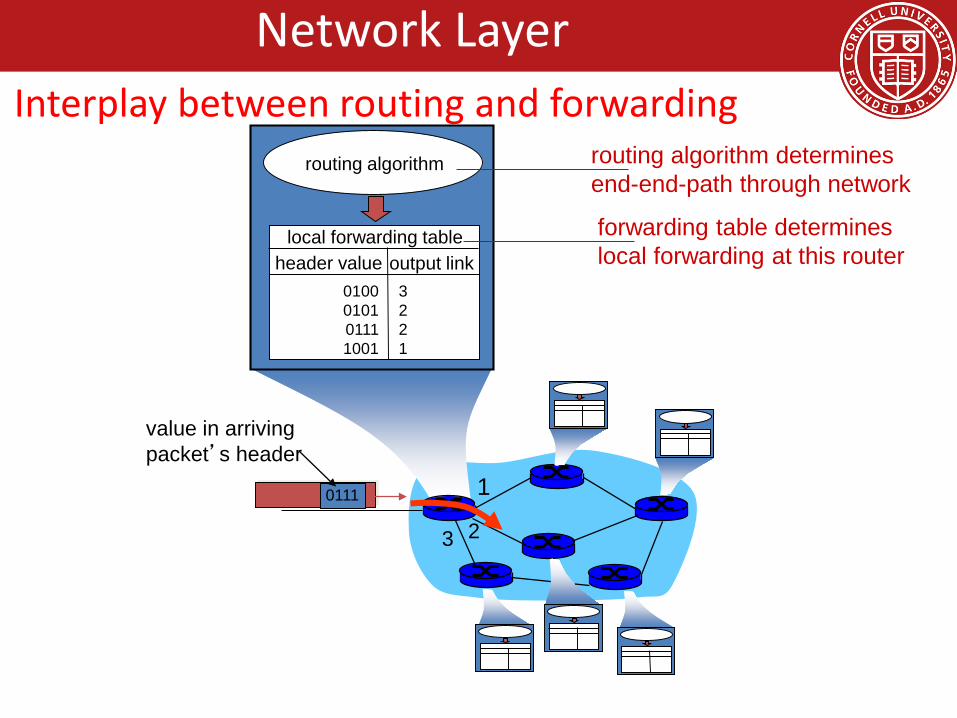
• forwarding: move packets from router’s input to appropriate router output
• routing: determine route taken by packets from source to dest.
– routing algorithms
analogy:
routing: process of planning trip from source to dest
forwarding: process of getting through single interchange
Network LayerTwo key functions
1
23
0111
value in arrivingpacket’s header
routing algorithm
local forwarding tableheader value output link
0100010101111001
3221
routing algorithm determinesend-end-path through network
forwarding table determineslocal forwarding at this router
Network LayerInterplay between routing and forwarding

Goals for Today• Network Layer
– Abstraction / services• Datagram vs Virtual Circuit (VC)
– Internet Protocol• IP Datagram format• Addressing• Hierarchical Routing
• Data Center Topologies– FatTree
• Backup Slides– DHCP and NAT– ICMP and Traceroute– IPv6– Hierarchical Routing: RIP, OSPF, BGP
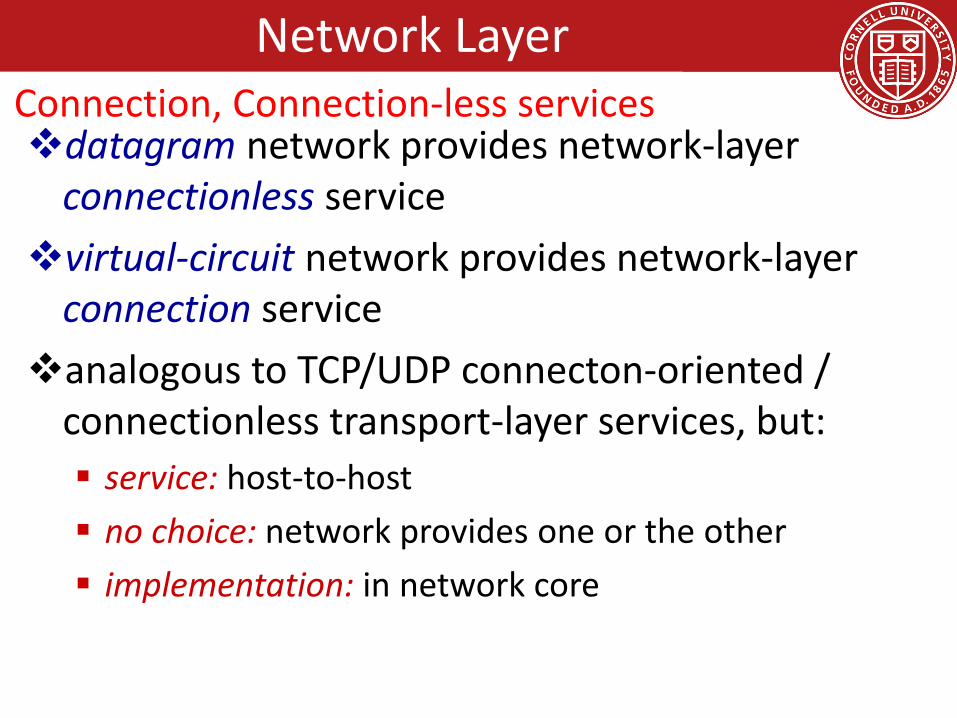
datagram network provides network-layer connectionless servicevirtual-circuit network provides network-layer
connection serviceanalogous to TCP/UDP connecton-oriented /
connectionless transport-layer services, but: service: host-to-host no choice: network provides one or the other implementation: in network core
Network LayerConnection, Connection-less services

• call setup, teardown for each call before data can flow• each packet carries VC identifier (not destination host address)• every router on source-dest path maintains “state” for each
passing connection• link, router resources (bandwidth, buffers) may be allocated to
VC (dedicated resources = predictable service)
“source-to-dest path behaves much like telephone circuit”– performance-wise– network actions along source-to-dest path
Network LayerVirtual Circuits (VC)

Network Layer
a VC consists of:1. path from source to destination2. VC numbers, one number for each link along path3. entries in forwarding tables in routers along path
packet belonging to VC carries VC number (rather than dest address)
VC number can be changed on each link. new VC number comes from forwarding table
Virtual Circuits (VC) implementation

12 22 32
1 23
VC numberinterfacenumber
Incoming interface Incoming VC # Outgoing interface Outgoing VC #
1 12 3 222 63 1 18 3 7 2 171 97 3 87… … … …
forwarding table innorthwest router:
VC routers maintain connection state information!
Network LayerVirtual Circuits (VC) forwarding table
applicationtransportnetworkdata linkphysical
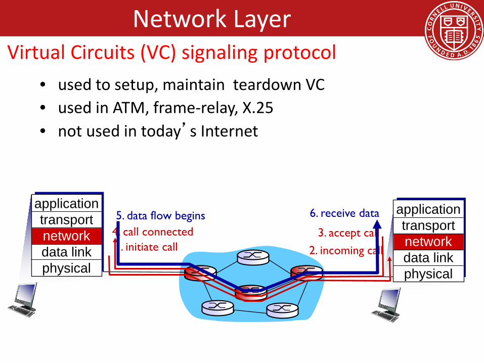
• used to setup, maintain teardown VC• used in ATM, frame-relay, X.25• not used in today’s Internet
1. initiate call 2. incoming call3. accept call4. call connected
5. data flow begins 6. receive dataapplicationtransportnetworkdata linkphysical
Network LayerVirtual Circuits (VC) signaling protocol

• no call setup at network layer• routers: no state about end-to-end connections
– no network-level concept of “connection”
• packets forwarded using destination host address
1. send datagrams
applicationtransportnetworkdata linkphysical
applicationtransportnetworkdata linkphysical
2. receive datagrams
Network LayerDatagram Networks

1
23
IP destination address in arriving packet’s header
routing algorithm
local forwarding tabledest address output link
address-range 1address-range 2address-range 3address-range 4
3221
4 billion IP addresses, so rather than list individual destination addresslist range of addresses(aggregate table entries)
Network LayerDatagram Forwarding Table

Destination Address Range
11001000 00010111 00010000 00000000through11001000 00010111 00010111 11111111
11001000 00010111 00011000 00000000through11001000 00010111 00011000 11111111
11001000 00010111 00011001 00000000through11001000 00010111 00011111 11111111
otherwise
Link Interface
0
1
2
3
Q: but what happens if ranges don’t divide up so nicely?
Network LayerDatagram Forwarding Table
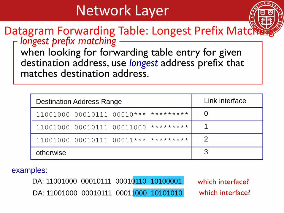
Destination Address Range
11001000 00010111 00010*** *********
11001000 00010111 00011000 *********
11001000 00010111 00011*** *********
otherwise
DA: 11001000 00010111 00011000 10101010
examples:DA: 11001000 00010111 00010110 10100001 which interface?
which interface?
when looking for forwarding table entry for given destination address, use longest address prefix that matches destination address.
longest prefix matching
Link interface
0
1
2
3
Network LayerDatagram Forwarding Table: Longest Prefix Matching

Internet (datagram)• data exchange among
computers– “elastic” service, no strict
timing req.• many link types
– different characteristics– uniform service difficult
• “smart” end systems (computers)– can adapt, perform control,
error recovery– simple inside network,
complexity at “edge”
ATM (VC)• evolved from telephony• human conversation:
– strict timing, reliability requirements
– need for guaranteed service
• “dumb” end systems– telephones– complexity inside network
Network LayerDatagram versus Virtual Circuits (VC)

Goals for Today• Network Layer
– Abstraction / services• Datagram vs Virtual Circuit (VC)
– Internet Protocol• IP Datagram format• IP Addressing• Hierarchical Routing
• Data Center Topologies– FatTree
• Backup Slides– DHCP and NAT– ICMP and Traceroute– IPv6– Hierarchical Routing: RIP, OSPF, BGP
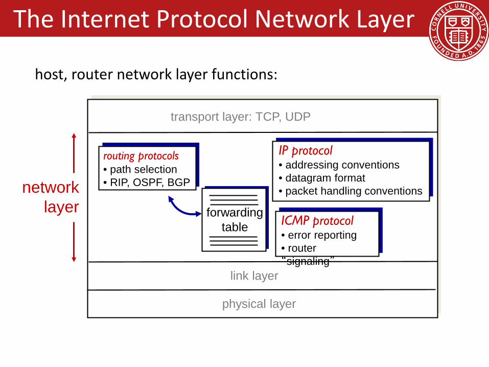
forwardingtable
host, router network layer functions:
routing protocols• path selection• RIP, OSPF, BGP
IP protocol• addressing conventions• datagram format• packet handling conventions
ICMP protocol• error reporting• router “signaling”
transport layer: TCP, UDP
link layer
physical layer
networklayer
The Internet Protocol Network Layer
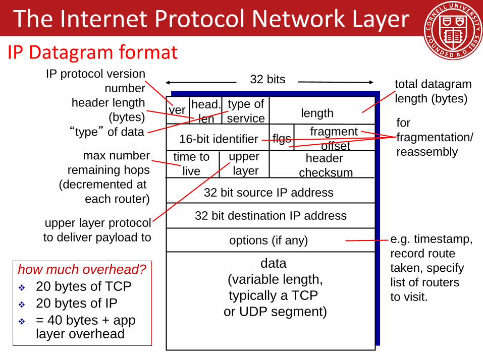
ver length
32 bits
data (variable length,typically a TCP
or UDP segment)
16-bit identifierheader
checksumtime to
live
32 bit source IP address
head.len
type ofservice
flgs fragmentoffset
upperlayer
32 bit destination IP address
options (if any)
IP protocol versionnumber
header length(bytes)
upper layer protocolto deliver payload to
total datagramlength (bytes)
“type” of data forfragmentation/reassemblymax number
remaining hops(decremented at
each router)
e.g. timestamp,record routetaken, specifylist of routers to visit.
how much overhead? 20 bytes of TCP 20 bytes of IP = 40 bytes + app
layer overhead
The Internet Protocol Network LayerIP Datagram format

• network links have MTU (max.transfer size) - largest possible link-level frame– different link types,
different MTUs • large IP datagram divided
(“fragmented”) within net– one datagram becomes
several datagrams– “reassembled” only at
final destination– IP header bits used to
identify, order related fragments
fragmentation:in: one large datagramout: 3 smaller datagrams
reassembly
…
…
The Internet Protocol Network LayerIP Fragmentation/Reassembly

ID=x
offset=0
fragflag=0
length=4000
ID=x
offset=0
fragflag=1
length=1500
ID=x
offset=185
fragflag=1
length=1500
ID=x
offset=370
fragflag=0
length=1040
one large datagram becomesseveral smaller datagrams
example: 4000 byte datagram MTU = 1500 bytes
1480 bytes in data field
offset =1480/8
The Internet Protocol Network LayerIP Fragmentation/Reassembly

Goals for Today• Network Layer
– Abstraction / services• Datagram vs Virtual Circuit (VC)
– Internet Protocol• IP Datagram format• IP Addressing• Hierarchical Routing
• Data Center Topologies– FatTree
• Backup Slides– DHCP and NAT– ICMP and Traceroute– IPv6– Hierarchical Routing: RIP, OSPF, BGP
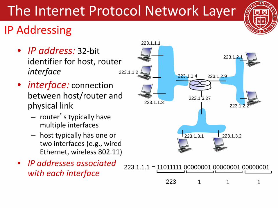
• IP address: 32-bit identifier for host, router interface
• interface: connection between host/router and physical link– router’s typically have
multiple interfaces– host typically has one or
two interfaces (e.g., wired Ethernet, wireless 802.11)
• IP addresses associated with each interface
223.1.1.1
223.1.1.2
223.1.1.3
223.1.1.4 223.1.2.9
223.1.2.2
223.1.2.1
223.1.3.2223.1.3.1
223.1.3.27
223.1.1.1 = 11011111 00000001 00000001 00000001
223 1 11
The Internet Protocol Network LayerIP Addressing

Q: how are interfaces actually connected?A: we’ll learn about that in chapter 5, 6.
223.1.1.1
223.1.1.2
223.1.1.3
223.1.1.4 223.1.2.9
223.1.2.2
223.1.2.1
223.1.3.2223.1.3.1
223.1.3.27
A: wired Ethernet interfaces connected by Ethernet switches
A: wireless WiFi interfaces connected by WiFi base station
For now: don’t need to worry about how one interface is connected to another (with no intervening router)
The Internet Protocol Network LayerIP Addressing

• IP address:–subnet part - high order
bits–host part - low order
bits • what’s a subnet ?
–device interfaces with same subnet part of IP address
–can physically reach each other without intervening router
network consisting of 3 subnets
223.1.1.1
223.1.1.3
223.1.1.4 223.1.2.9
223.1.3.2223.1.3.1
subnet
223.1.1.2
223.1.3.27223.1.2.2
223.1.2.1
The Internet Protocol Network LayerSubnets

recipeto determine the
subnets, detach each interface from its host or router, creating islands of isolated networks
each isolated network is called a subnet
subnet mask: /24
223.1.1.0/24223.1.2.0/24
223.1.3.0/24
223.1.1.1
223.1.1.3
223.1.1.4 223.1.2.9
223.1.3.2223.1.3.1
subnet
223.1.1.2
223.1.3.27223.1.2.2
223.1.2.1
The Internet Protocol Network LayerSubnets

how many? 223.1.1.1
223.1.1.3
223.1.1.4
223.1.2.2223.1.2.1
223.1.2.6
223.1.3.2223.1.3.1
223.1.3.27
223.1.1.2
223.1.7.0
223.1.7.1223.1.8.0223.1.8.1
223.1.9.1
223.1.9.2
The Internet Protocol Network LayerSubnets

CIDR: Classless InterDomain Routing subnet portion of address of arbitrary length address format: a.b.c.d/x, where x is # bits in
subnet portion of address
11001000 00010111 00010000 00000000
subnetpart
hostpart
200.23.16.0/23
The Internet Protocol Network LayerIP Addressing: CIDR (Classess InterDomain Routing)

Q: How does a host get IP address?
• hard-coded by system admin in a file– Windows: control-panel->network->configuration->tcp/ip-
>properties– UNIX: /etc/rc.config
• DHCP: Dynamic Host Configuration Protocol: dynamically get address from as server– “plug-and-play”
The Internet Protocol Network LayerIP Addresses: How to get one?

Goals for Today• Network Layer
– Abstraction / services• Datagram vs Virtual Circuit (VC)
– Internet Protocol• IP Datagram format• IP Addressing / subnets• Routing Algorithms• Hierarchical Routing
• Data Center Topologies– FatTree
• Backup Slides– DHCP and NAT– ICMP and Traceroute– IPv6– Hierarchical Routing: RIP, OSPF, BGP

1
23
IP destination address in arriving packet’s header
routing algorithm
local forwarding tabledest address output link
address-range 1address-range 2address-range 3address-range 4
3221
routing algorithm determinesend-end-path through network
forwarding table determineslocal forwarding at this router
The Internet Protocol Network LayerInterplay between routing and forwarding
u
yx
wv
z2
21
3
1
1
2
53
5
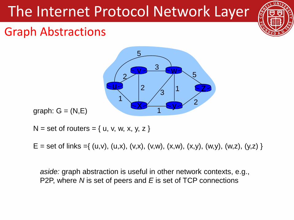
graph: G = (N,E)
N = set of routers = { u, v, w, x, y, z }
E = set of links ={ (u,v), (u,x), (v,x), (v,w), (x,w), (x,y), (w,y), (w,z), (y,z) }
aside: graph abstraction is useful in other network contexts, e.g., P2P, where N is set of peers and E is set of TCP connections
The Internet Protocol Network LayerGraph Abstractions

u
yx
wv
z2
21
3
1
1
2
53
5 c(x,x’) = cost of link (x,x’)e.g., c(w,z) = 5
cost could always be 1, or inversely related to bandwidth,or inversely related to congestion
cost of path (x1, x2, x3,…, xp) = c(x1,x2) + c(x2,x3) + … + c(xp-1,xp)
key question: what is the least-cost path between u and z ?routing algorithm: algorithm that finds that least cost path
The Internet Protocol Network LayerGraph Abstractions: Costs

Q: global or decentralized information?
global:• all routers have complete
topology, link cost info• “link state” algorithmsdecentralized: • router knows physically-
connected neighbors, link costs to neighbors
• iterative process of computation, exchange of info with neighbors
• “distance vector” algorithms
Q: static or dynamic?static: routes change slowly over
timedynamic: routes change more
quickly periodic update in response to link cost
changes
The Internet Protocol Network LayerRouting Algorithm Classifications

Goals for Today• Network Layer
– Abstraction / services• Datagram vs Virtual Circuit (VC)
– Internet Protocol• IP Datagram format• IP Addressing / subnets• Routing Algorithms• Hierarchical Routing
• Data Center Topologies– FatTree
• Backup Slides– DHCP and NAT– ICMP and Traceroute– IPv6– Hierarchical Routing: RIP, OSPF, BGP
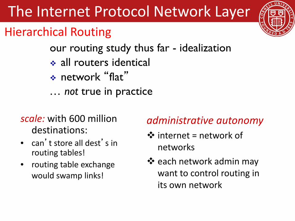
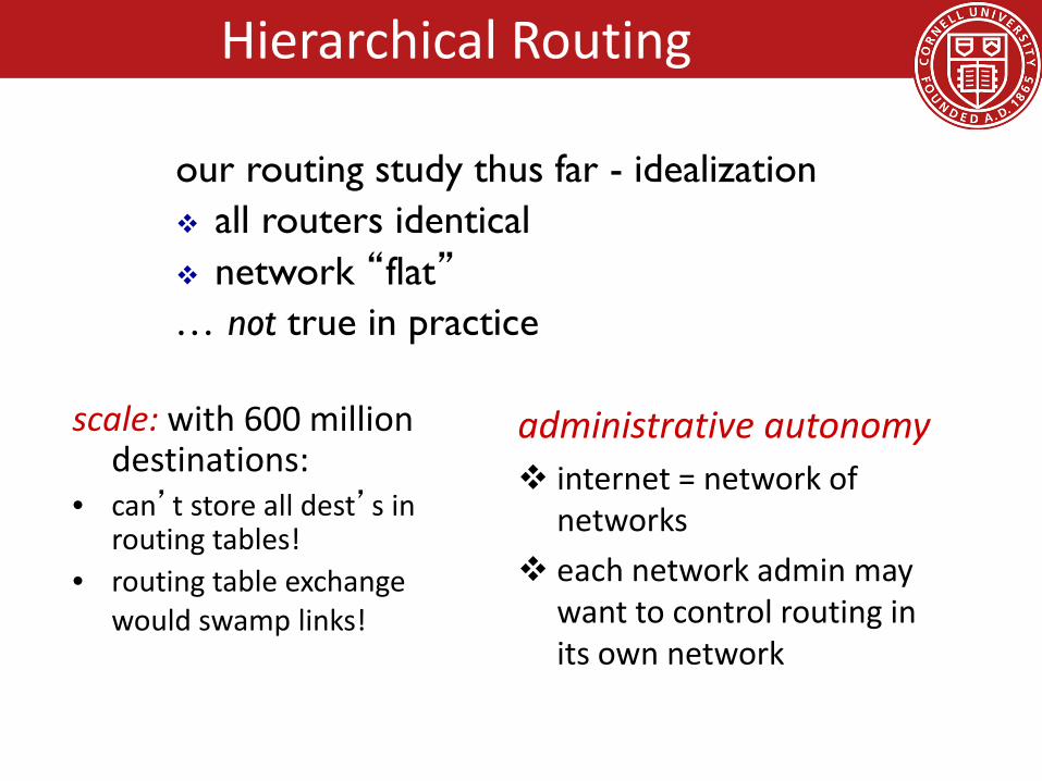
scale: with 600 million destinations:
• can’t store all dest’s in routing tables!
• routing table exchange would swamp links!
administrative autonomy internet = network of
networks each network admin may
want to control routing in its own network
our routing study thus far - idealization all routers identical network “flat”… not true in practice
The Internet Protocol Network LayerHierarchical Routing
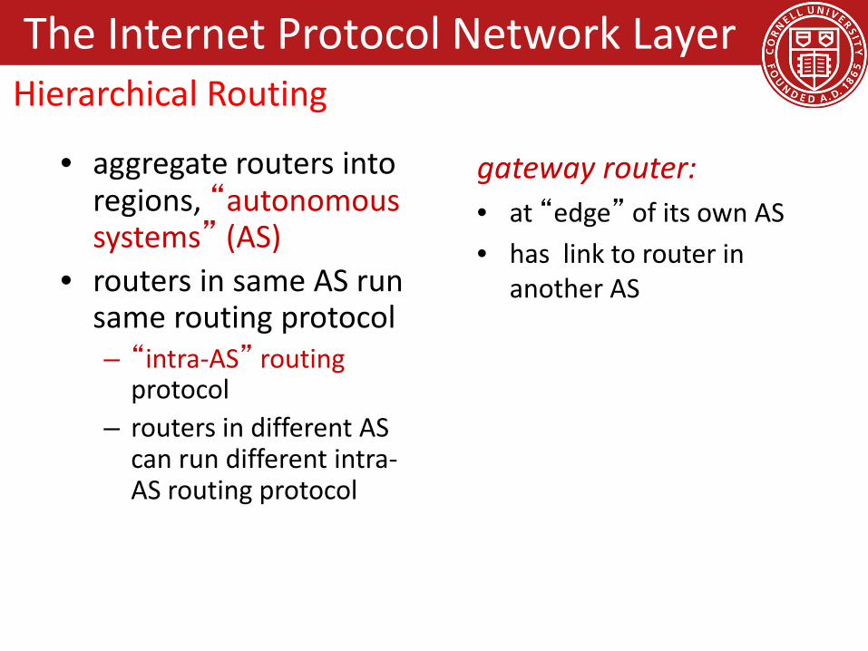
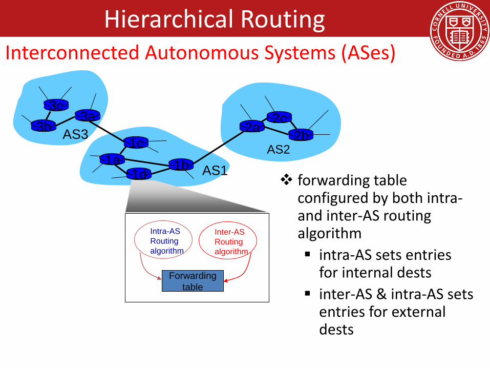
• aggregate routers into regions, “autonomous systems” (AS)
• routers in same AS run same routing protocol– “intra-AS” routing
protocol– routers in different AS
can run different intra-AS routing protocol
gateway router:• at “edge” of its own AS• has link to router in
another AS
The Internet Protocol Network LayerHierarchical Routing

3b
1d
3a
1c2aAS3
AS1AS2
1a
2c2b
1b
Intra-ASRouting algorithm
Inter-ASRouting algorithm
Forwardingtable
3c
forwarding table configured by both intra-and inter-AS routing algorithm intra-AS sets entries
for internal dests inter-AS & intra-AS sets
entries for external dests
The Internet Protocol Network LayerHierarchical Routing: Interconnected
Autonomous Systems (AS)

also known as interior gateway protocols (IGP)most common intra-AS routing protocols: RIP: Routing Information Protocol OSPF: Open Shortest Path First IGRP: Interior Gateway Routing Protocol (Cisco
proprietary)
The Internet Protocol Network LayerHierarchical Routing: Intra-AS routing

• BGP (Border Gateway Protocol): the de facto inter-domain routing protocol– “glue that holds the Internet together”
• BGP provides each AS a means to:– eBGP: obtain subnet reachability information from
neighboring ASs.– iBGP: propagate reachability information to all AS-
internal routers.– determine “good” routes to other networks based
on reachability information and policy.• allows subnet to advertise its existence to rest
of Internet: “I am here”
The Internet Protocol Network LayerHierarchical Routing: Inter-AS routing—BGP

• advertised prefix includes BGP attributes – prefix + attributes = “route”
• two important attributes:– AS-PATH: contains ASs through which prefix advertisement
has passed: e.g., AS 67, AS 17 – NEXT-HOP: indicates specific internal-AS router to next-
hop AS. (may be multiple links from current AS to next-hop-AS)
• gateway router receiving route advertisement uses import policy to accept/decline– e.g., never route through AS x– policy-based routing
The Internet Protocol Network LayerHierarchical Routing: Inter-AS routing—BGPPath Attributes and BGP Routes

router may learn about more than 1 route to destination AS, selects route based on:
1. local preference value attribute: policy decision
2. shortest AS-PATH 3. closest NEXT-HOP router: hot potato routing4. additional criteria
The Internet Protocol Network LayerHierarchical Routing: Inter-AS routing—BGPBGP Route Selection

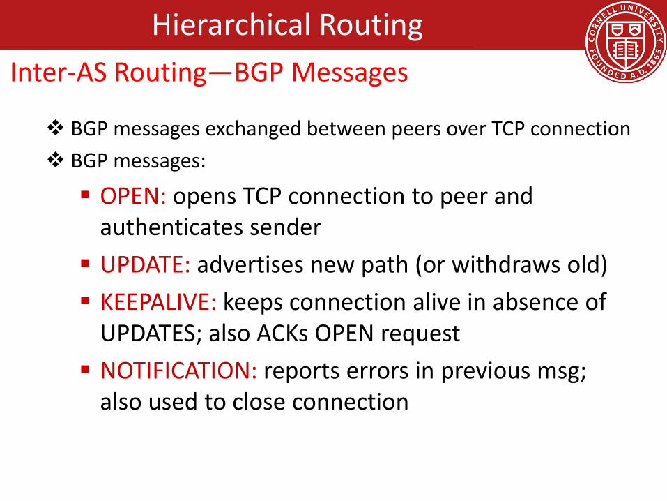
BGP messages exchanged between peers over TCP connection BGP messages:
OPEN: opens TCP connection to peer and authenticates sender UPDATE: advertises new path (or withdraws old) KEEPALIVE: keeps connection alive in absence of
UPDATES; also ACKs OPEN request NOTIFICATION: reports errors in previous msg;
also used to close connection
The Internet Protocol Network LayerHierarchical Routing: Inter-AS routing—BGPBGP Messages

A,B,C are provider networks X,W,Y are customer (of provider networks) X is dual-homed: attached to two networks X does not want to route from B via X to C .. so X will not advertise to B a route to C
A
B
C
WX
Y
legend:
customer network:
providernetwork
The Internet Protocol Network LayerHierarchical Routing: Inter-AS routing—BGPBGP Routing Policy

A advertises path AW to B B advertises path BAW to X Should B advertise path BAW to C?
No way! B gets no “revenue” for routing CBAW since neither W nor C are B’s customers
B wants to force C to route to w via A B wants to route only to/from its customers!
A
B
C
WX
Y
legend:
customer network:
providernetwork
The Internet Protocol Network LayerHierarchical Routing: Inter-AS routing—BGPBGP Routing Policy
policy: inter-AS: admin wants control over how its traffic
routed, who routes through its net. intra-AS: single admin, so no policy decisions neededscale:hierarchical routing saves table size, reduced update
trafficperformance: intra-AS: can focus on performance inter-AS: policy may dominate over performance
The Internet Protocol Network LayerHierarchical Routing: Intra vs Inter-AS routing
Goals for Today• Network Layer
– Abstraction / services• Datagram vs Virtual Circuit (VC)
– Internet Protocol• IP Datagram format• IP Addressing / subnets• Routing Algorithms• Hierarchical Routing
• Data Center Topologies– FatTree
• Backup Slides– DHCP and NAT– ICMP and Traceroute– IPv6– Hierarchical Routing: RIP, OSPF, BGP

• A scalable, commodity data center network architecture, M. Al-Fares, A. Loukissas, and A. Vahdat. ACM SIGCOMM Computer Communication Review, Volume 38, Issue 4 (August 2008), pages 63-74.
Data Center Topology: FatTree

• Structure and Properties of a Data Center• Desired properties in a DC Architecture• Fat tree based solution
Data Center Topology: FatTreeOverview

Topology: 2 layers: 5K to 8K hosts 3 layer: >25K hosts Switches:○ Leaves: have N GigE ports (48-288) + N 10 GigE uplinks to one
or more layers of network elements○ Higher levels: N 10 GigE ports (32-128)
Multi-path Routing: Ex. ECMP○ without it, the largest cluster = 1,280 nodes○ Performs static load splitting among flows○ Lead to oversubscription for simple comm. patterns○ Routing table entries grows multiplicatively with number of
paths, cost ++, lookup latency ++
Data Center Topology: FatTreeBackground
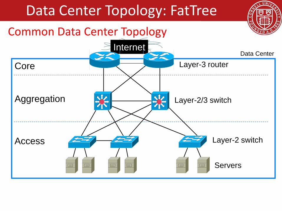
Internet
Servers
Layer-2 switchAccess
Data Center
Layer-2/3 switchAggregation
Layer-3 routerCore
Data Center Topology: FatTreeCommon Data Center Topology

• Single point of failure• Over subscript of links higher up in the topology
– Trade off between cost and provisioning
Data Center Topology: FatTreeIssues with Traditional Data Center Topology

Oversubscription: Ratio of the worst-case achievable aggregate bandwidth
among the end hosts to the total bisection bandwidth of a particular communication topology
Lower the total cost of the design Typical designs: factor of 2:5:1 (400 Mbps)to 8:1(125
Mbps)Cost: Edge: $7,000 for each 48-port GigE switch Aggregation and core: $700,000 for 128-port 10GigE
switches Cabling costs are not considered!
Data Center Topology: FatTreeIssues with Traditional Data Center Topology

• Backwards compatible with existing infrastructure– No changes in application– Support of layer 2 (Ethernet)
• Cost effective– Low power consumption & heat emission– Cheap infrastructure
• Allows host communication at line speed
Data Center Topology: FatTreeProperties of Desired Solution
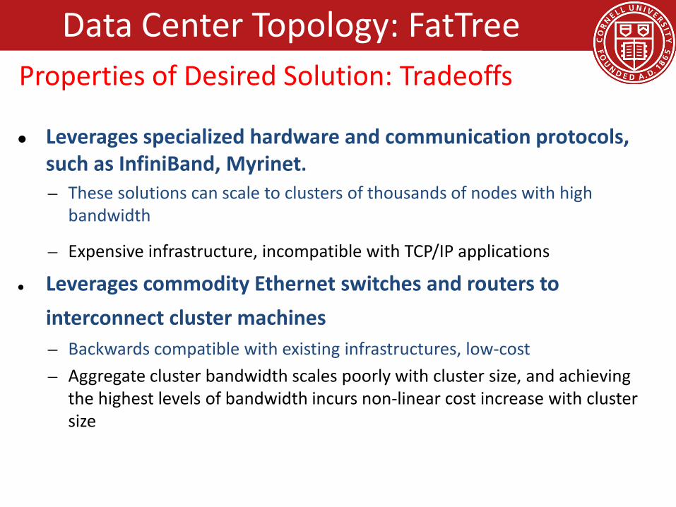
Leverages specialized hardware and communication protocols, such as InfiniBand, Myrinet.– These solutions can scale to clusters of thousands of nodes with high
bandwidth
– Expensive infrastructure, incompatible with TCP/IP applications
Leverages commodity Ethernet switches and routers to interconnect cluster machines– Backwards compatible with existing infrastructures, low-cost– Aggregate cluster bandwidth scales poorly with cluster size, and achieving
the highest levels of bandwidth incurs non-linear cost increase with cluster size
Data Center Topology: FatTreeProperties of Desired Solution: Tradeoffs

• Adopt a special instance of a Clos topology
• Similar trends in telephone switches led to designing a topology with high bandwidth by interconnecting smaller commodity switches.
Data Center Topology: FatTreeProposed Solution: FatTree (Clos Network)

• Inter-connect racks (of servers) using a fat-tree topologyK-ary fat tree: three-layer topology (edge, aggregation and core)– each pod consists of (k/2)2 servers & 2 layers of k/2 k-port switches– each edge switch connects to k/2 servers & k/2 aggr. switches – each aggr. switch connects to k/2 edge & k/2 core switches– (k/2)2 core switches: each connects to k pods
Fat-tree with K=4
Data Center Topology: FatTreeFatTree Based Data Center Architecture

• Why Fat-Tree?– Fat tree has identical bandwidth at any bisections– Each layer has the same aggregated bandwidth
• Can be built using cheap devices with uniform capacity– Each port supports same speed as end host– All devices can transmit at line speed if packets are distributed
uniform along available paths
• Great scalability: k-port switch supports k3/4 servers
Data Center Topology: FatTreeFatTree Based Data Center Architecture
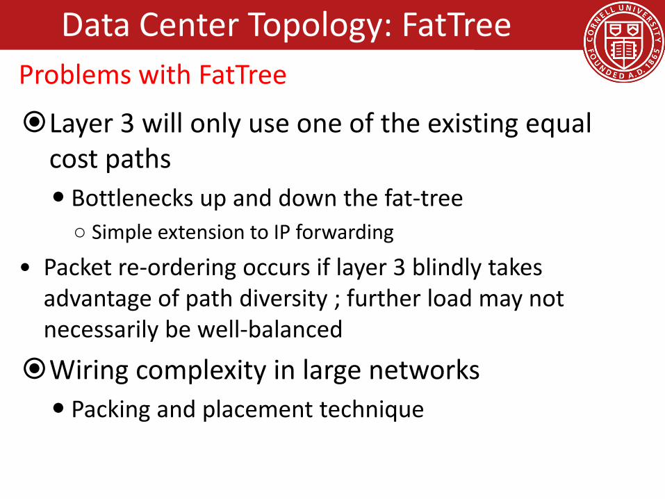
Layer 3 will only use one of the existing equal cost paths Bottlenecks up and down the fat-tree○ Simple extension to IP forwarding
• Packet re-ordering occurs if layer 3 blindly takes advantage of path diversity ; further load may not necessarily be well-balanced
Wiring complexity in large networks Packing and placement technique
Data Center Topology: FatTreeProblems with FatTree

Enforce a special (IP) addressing scheme in DC unused.PodNumber.switchnumber.Endhost Allows host attached to same switch to route only
through switch Allows inter-pod traffic to stay within pod
Data Center Topology: FatTreeFatTree Modified
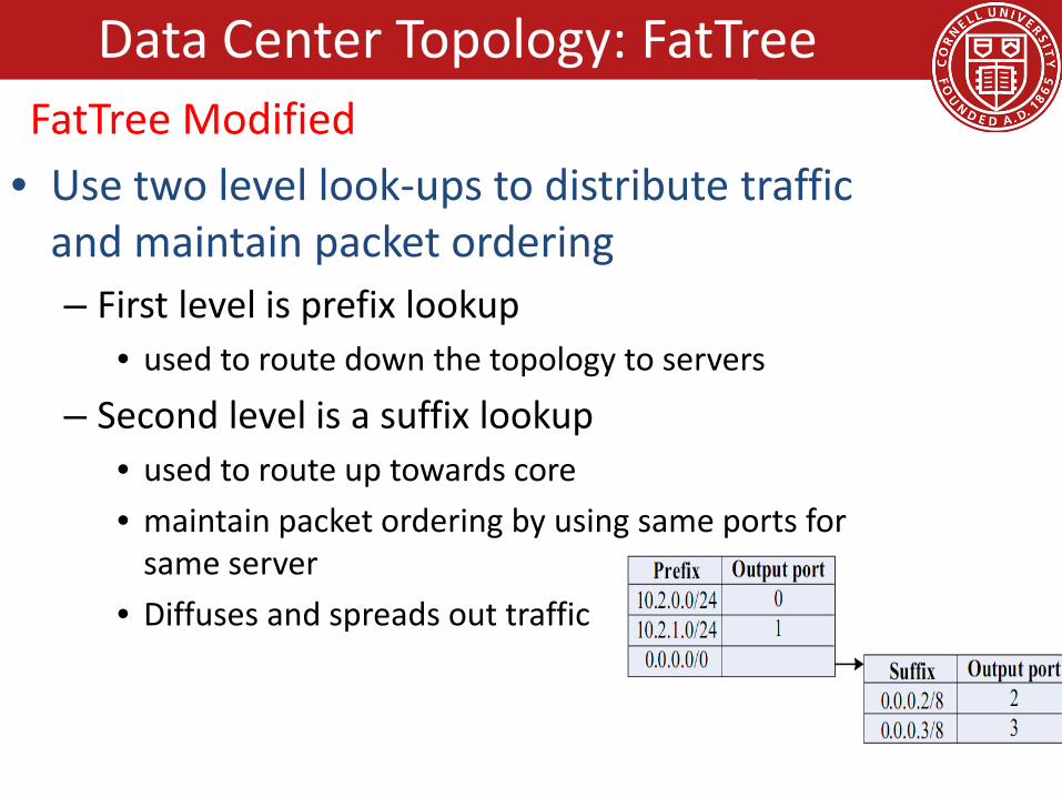
• Use two level look-ups to distribute traffic and maintain packet ordering– First level is prefix lookup
• used to route down the topology to servers
– Second level is a suffix lookup• used to route up towards core• maintain packet ordering by using same ports for
same server• Diffuses and spreads out traffic
Data Center Topology: FatTreeFatTree Modified

Before Next time• Project Proposal
– due this Friday– Project group meeting Tuesday, 4:15pm, in 122 Gates Hall– Meet with groups, TA, and professor
• Lab1– Lab1 help session in MEng Lab, Wednesday, Sept 10, during lecture
time– Single threaded TCP proxy– Due this Friday
• No required reading and review due• But, review chapter 5 from the book, Data Link and Physical
Layer– We will also briefly discuss data center topologies
• Check website for updated schedule

Goals for Today• Network Layer
– Abstraction / services• Datagram vs Virtual Circuit (VC)
– Internet Protocol• IP Datagram format• IP Addressing• Hierarchical Routing
• Data Center Topologies– FatTree
• Backup Slides– DHCP and NAT– ICMP and Traceroute– IPv6– Hierarchical Routing: RIP, OSPF, BGP

DHCP (Dynamic Host Configuration Protocol)
Q: How does a host get IP address?
• hard-coded by system admin in a file– Windows: control-panel->network->configuration->tcp/ip-
>properties– UNIX: /etc/rc.config
• DHCP: Dynamic Host Configuration Protocol: dynamically get address from as server– “plug-and-play”
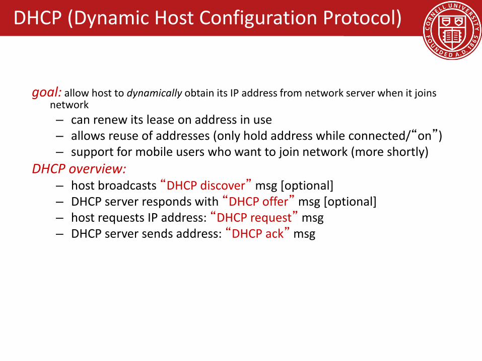
goal: allow host to dynamically obtain its IP address from network server when it joins network– can renew its lease on address in use– allows reuse of addresses (only hold address while connected/“on”)– support for mobile users who want to join network (more shortly)
DHCP overview:– host broadcasts “DHCP discover” msg [optional]– DHCP server responds with “DHCP offer” msg [optional]– host requests IP address: “DHCP request” msg– DHCP server sends address: “DHCP ack” msg
DHCP (Dynamic Host Configuration Protocol)

223.1.1.0/24
223.1.2.0/24
223.1.3.0/24
223.1.1.1
223.1.1.3
223.1.1.4 223.1.2.9
223.1.3.2223.1.3.1
223.1.1.2
223.1.3.27223.1.2.2
223.1.2.1
DHCPserver
arriving DHCPclient needs address in thisnetwork
DHCP (Dynamic Host Configuration Protocol)
Client-Server Scenario

DHCP server: 223.1.2.5 arrivingclient
DHCP discover
src : 0.0.0.0, 68 dest.: 255.255.255.255,67yiaddr: 0.0.0.0transaction ID: 654
DHCP offersrc: 223.1.2.5, 67 dest: 255.255.255.255, 68yiaddrr: 223.1.2.4transaction ID: 654lifetime: 3600 secs
DHCP requestsrc: 0.0.0.0, 68 dest:: 255.255.255.255, 67yiaddrr: 223.1.2.4transaction ID: 655lifetime: 3600 secs
DHCP ACKsrc: 223.1.2.5, 67 dest: 255.255.255.255, 68yiaddrr: 223.1.2.4transaction ID: 655lifetime: 3600 secs
DHCP (Dynamic Host Configuration Protocol)
Client-Server Scenario

DHCP can return more than just allocated IPaddress on subnet: address of first-hop router for client name and IP address of DNS sever network mask (indicating network versus host portion
of address)
DHCP (Dynamic Host Configuration Protocol)

connecting laptop needs its IP address, addr of first-hop router, addr of DNS server: use DHCP
router with DHCP server built into router
DHCP request encapsulated in UDP, encapsulated in IP, encapsulated in 802.1 Ethernet
Ethernet frame broadcast (dest: FFFFFFFFFFFF) on LAN, received at router running DHCP server
Ethernet demuxed to IP demuxed, UDP demuxed to DHCP
168.1.1.1
DHCPUDP
IPEthPhy
DHCP
DHCP
DHCP
DHCP
DHCP
DHCPUDP
IPEthPhy
DHCP
DHCP
DHCP
DHCPDHCP
DHCP (Dynamic Host Configuration Protocol)
DHCP Example

• DCP server formulates DHCP ACK containing client’s IP address, IP address of first-hop router for client, name & IP address of DNS server
encapsulation of DHCP server, frame forwarded to client, demuxing up to DHCP at client
router with DHCP server built into router
DHCP
DHCP
DHCP
DHCP
DHCPUDP
IPEthPhy
DHCP
DHCPUDP
IPEthPhy
DHCP
DHCP
DHCP
DHCP
client now knows its IP address, name and IP address of DSN server, IP address of its first-hop router
DHCP (Dynamic Host Configuration Protocol)
DHCP Example
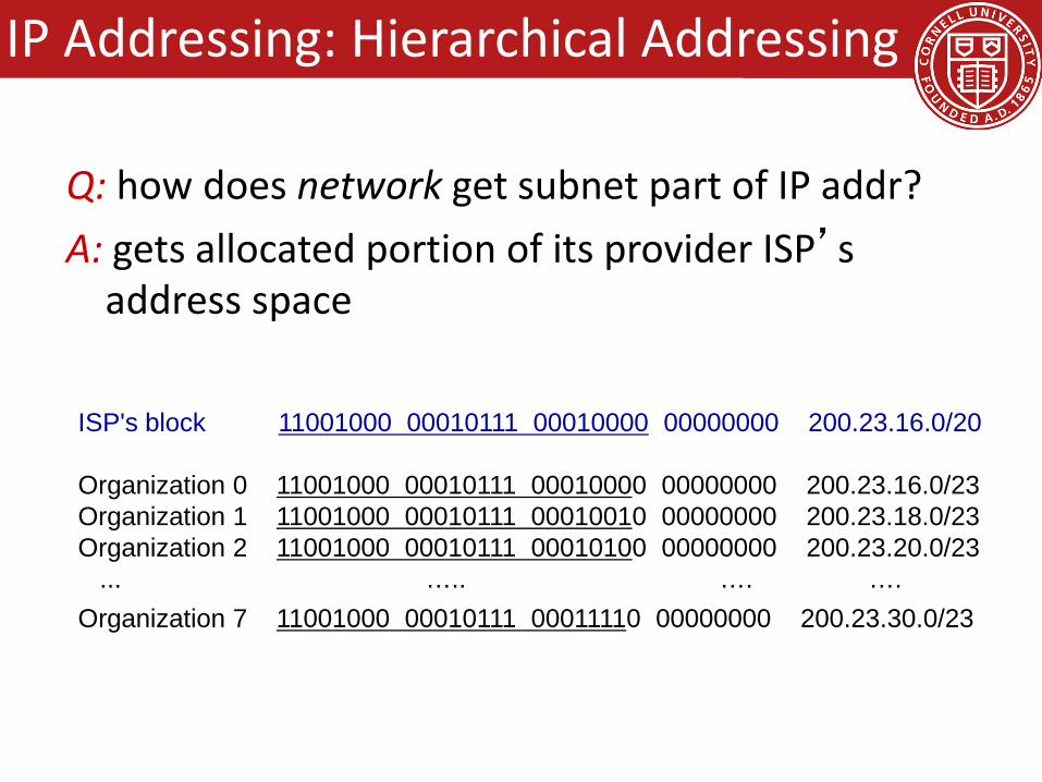
Q: how does network get subnet part of IP addr?A: gets allocated portion of its provider ISP’s
address space
ISP's block 11001000 00010111 00010000 00000000 200.23.16.0/20
Organization 0 11001000 00010111 00010000 00000000 200.23.16.0/23 Organization 1 11001000 00010111 00010010 00000000 200.23.18.0/23 Organization 2 11001000 00010111 00010100 00000000 200.23.20.0/23
... ….. …. ….Organization 7 11001000 00010111 00011110 00000000 200.23.30.0/23
IP Addressing: Hierarchical Addressing
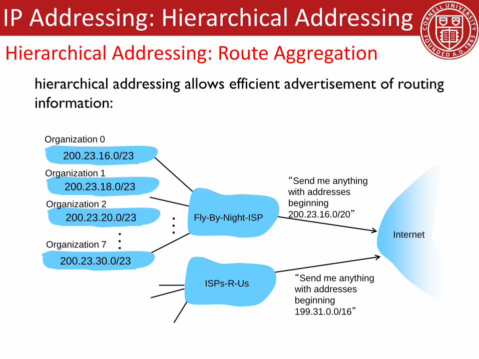
“Send me anythingwith addresses beginning 200.23.16.0/20”
200.23.16.0/23
200.23.18.0/23
200.23.30.0/23
Fly-By-Night-ISP
Organization 0
Organization 7Internet
Organization 1
ISPs-R-Us “Send me anythingwith addresses beginning 199.31.0.0/16”
200.23.20.0/23Organization 2
...
...
hierarchical addressing allows efficient advertisement of routing information:
IP Addressing: Hierarchical AddressingHierarchical Addressing: Route Aggregation

ISPs-R-Us has a more specific route to Organization 1
“Send me anythingwith addresses beginning 200.23.16.0/20”
200.23.16.0/23
200.23.18.0/23
200.23.30.0/23
Fly-By-Night-ISP
Organization 0
Organization 7Internet
Organization 1
ISPs-R-Us “Send me anythingwith addresses beginning 199.31.0.0/16or 200.23.18.0/23”
200.23.20.0/23Organization 2
...
...
IP Addressing: Hierarchical Addressing
Q: how does an ISP get block of addresses?A: ICANN: Internet Corporation for Assigned
Names and Numbers http://www.icann.org/ allocates addresses manages DNS assigns domain names, resolves disputes
IP Addressing: Hierarchical Addressing

Goals for Today• Network Layer
– Abstraction / services• Datagram vs Virtual Circuit (VC)
– Internet Protocol• IP Datagram format• IP Addressing• Hierarchical Routing
• Data Center Topologies– FatTree
• Backup Slides– DHCP and NAT– ICMP and Traceroute– IPv6– Hierarchical Routing: RIP, OSPF, BGP

10.0.0.1
10.0.0.2
10.0.0.3
10.0.0.4
138.76.29.7
local network(e.g., home network)
10.0.0/24
rest ofInternet
datagrams with source or destination in this networkhave 10.0.0/24 address for source, destination (as usual)
all datagrams leaving localnetwork have same single
source NAT IP address: 138.76.29.7,different source
port numbers
NAT (Network Address Translation)
motivation: local network uses just one IP address as far as outside world is concerned: range of addresses not needed from ISP: just one
IP address for all devices can change addresses of devices in local network
without notifying outside world can change ISP without changing addresses of
devices in local network devices inside local net not explicitly addressable,
visible by outside world (a security plus)
NAT (Network Address Translation)

implementation: NAT router must: outgoing datagrams: replace (source IP address, port #)
of every outgoing datagram to (NAT IP address, new port #)
. . . remote clients/servers will respond using (NAT IP address, new port #) as destination addr
remember (in NAT translation table) every (source IP address, port #) to (NAT IP address, new port #) translation pair
incoming datagrams: replace (NAT IP address, new port #) in dest fields of every incoming datagram with corresponding (source IP address, port #) stored in NAT table
NAT (Network Address Translation)

10.0.0.1
10.0.0.2
10.0.0.3
S: 10.0.0.1, 3345D: 128.119.40.186, 80
110.0.0.4
138.76.29.7
1: host 10.0.0.1 sends datagram to 128.119.40.186, 80
NAT translation tableWAN side addr LAN side addr138.76.29.7, 5001 10.0.0.1, 3345…… ……
S: 128.119.40.186, 80 D: 10.0.0.1, 3345 4
S: 138.76.29.7, 5001D: 128.119.40.186, 802
2: NAT routerchanges datagramsource addr from10.0.0.1, 3345 to138.76.29.7, 5001,updates table
S: 128.119.40.186, 80 D: 138.76.29.7, 5001 3
3: reply arrivesdest. address:138.76.29.7, 5001
4: NAT routerchanges datagramdest addr from138.76.29.7, 5001 to 10.0.0.1, 3345
NAT (Network Address Translation)

16-bit port-number field: 60,000 simultaneous connections with a single LAN-
side address!
NAT is controversial: routers should only process up to layer 3 violates end-to-end argument
• NAT possibility must be taken into account by app designers, e.g., P2P applications
address shortage should instead be solved by IPv6
NAT (Network Address Translation)

• client wants to connect to server with address 10.0.0.1– server address 10.0.0.1 local to
LAN (client can’t use it as destination addr)
– only one externally visible NATed address: 138.76.29.7
• solution1: statically configure NAT to forward incoming connection requests at given port to server– e.g., (123.76.29.7, port 2500)
always forwarded to 10.0.0.1 port 25000
10.0.0.1
10.0.0.4
NAT router
138.76.29.7
client
?
NAT (Network Address Translation)NAT Traversal Problem

solution 2: Universal Plug and Play (UPnP) Internet Gateway Device (IGD) Protocol. Allows NATed host to: learn public IP address
(138.76.29.7) add/remove port
mappings (with lease times)
i.e., automate static NAT port map configuration
10.0.0.1
NAT router
IGD
NAT (Network Address Translation)NAT Traversal Problem
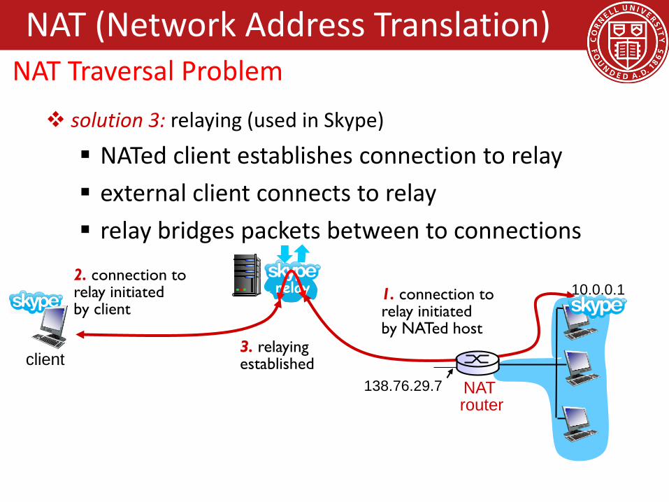
solution 3: relaying (used in Skype)
NATed client establishes connection to relay external client connects to relay relay bridges packets between to connections
138.76.29.7
client
1. connection torelay initiatedby NATed host
2. connection torelay initiatedby client
3. relaying established
NAT router
10.0.0.1
NAT (Network Address Translation)NAT Traversal Problem

Goals for Today• Network Layer
– Abstraction / services• Datagram vs Virtual Circuit (VC)
– Internet Protocol• IP Datagram format• IP Addressing• Hierarchical Routing
• Data Center Topologies– FatTree
• Backup Slides– DHCP and NAT– ICMP and Traceroute– IPv6– Hierarchical Routing: RIP, OSPF, BGP

• used by hosts & routers to communicate network-level information– error reporting:
unreachable host, network, port, protocol
– echo request/reply (used by ping)
• network-layer “above” IP:– ICMP msgs carried in IP
datagrams• ICMP message: type, code
plus first 8 bytes of IP datagram causing error
Type Code description0 0 echo reply (ping)3 0 dest. network unreachable3 1 dest host unreachable3 2 dest protocol unreachable3 3 dest port unreachable3 6 dest network unknown3 7 dest host unknown4 0 source quench (congestion
control - not used)8 0 echo request (ping)9 0 route advertisement10 0 router discovery11 0 TTL expired12 0 bad IP header
ICMP (Internet control message protocol)

source sends series of UDP segments to dest first set has TTL =1 second set has TTL=2, etc. unlikely port number
when nth set of datagrams arrives to nth router: router discards datagrams and sends source ICMP
messages (type 11, code 0) ICMP messages includes
name of router & IP address
when ICMP messages arrives, source records RTTs
stopping criteria: UDP segment eventually
arrives at destination host destination returns ICMP
“port unreachable”message (type 3, code 3)
source stops
3 probes
3 probes
3 probes
ICMP (Internet control message protocol)ICMP and Traceroute
Goals for Today• Network Layer
– Abstraction / services• Datagram vs Virtual Circuit (VC)
– Internet Protocol• IP Datagram format• IP Addressing• Hierarchical Routing
• Data Center Topologies– FatTree
• Backup Slides– DHCP and NAT– ICMP and Traceroute– IPv6– Hierarchical Routing: RIP, OSPF, BGP

initial motivation: 32-bit address space soon to be completely allocated. additional motivation: header format helps speed processing/forwarding header changes to facilitate QoS
IPv6 datagram format: fixed-length 40 byte header no fragmentation allowed
IPv6
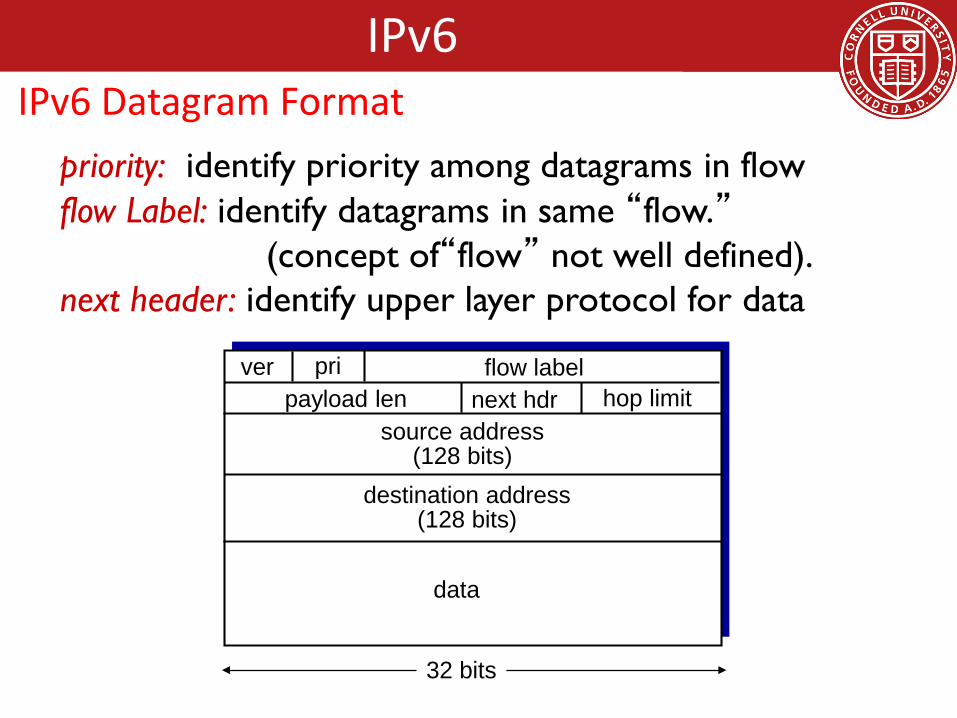
priority: identify priority among datagrams in flowflow Label: identify datagrams in same “flow.”
(concept of“flow” not well defined).next header: identify upper layer protocol for data
data
destination address(128 bits)
source address(128 bits)
payload len next hdr hop limitflow labelpriver
32 bits
IPv6IPv6 Datagram Format
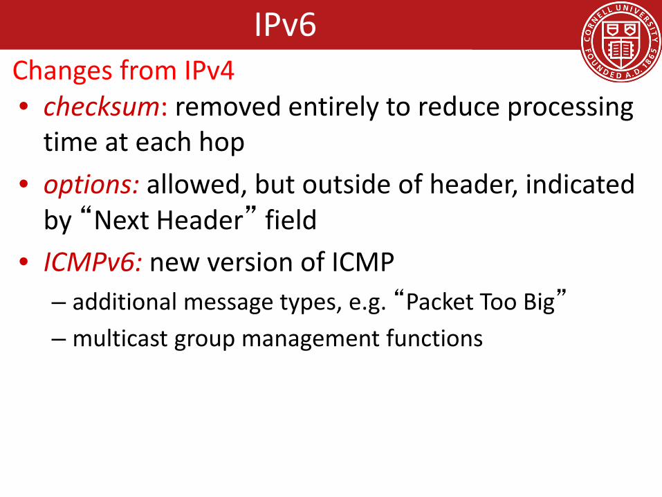
• checksum: removed entirely to reduce processing time at each hop
• options: allowed, but outside of header, indicated by “Next Header” field
• ICMPv6: new version of ICMP– additional message types, e.g. “Packet Too Big”
– multicast group management functions
IPv6Changes from IPv4

• not all routers can be upgraded simultaneously– no “flag days”– how will network operate with mixed IPv4 and IPv6
routers? • tunneling: IPv6 datagram carried as payload in
IPv4 datagram among IPv4 routers
IPv4 source, dest addr IPv4 header fields
IPv4 datagramIPv6 datagram
IPv4 payload
UDP/TCP payloadIPv6 source dest addr
IPv6 header fields
IPv6Transition to IPv6 from IPv4

physical view:IPv4 IPv4
A B
IPv6 IPv6
E
IPv6 IPv6
FC D
logical view:
IPv4 tunnel connecting IPv6 routers E
IPv6 IPv6
FA B
IPv6 IPv6
IPv6Transition to IPv6 from IPv4 via Tunneling
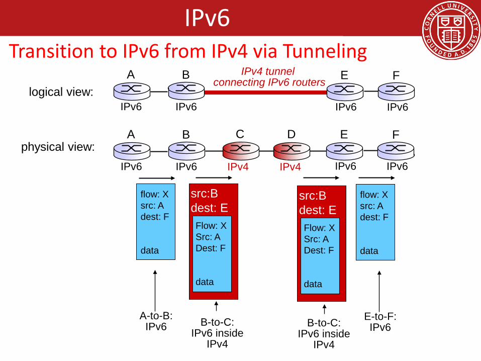
flow: Xsrc: Adest: F
data
A-to-B:IPv6
Flow: XSrc: ADest: F
data
src:Bdest: E
B-to-C:IPv6 inside
IPv4
E-to-F:IPv6
flow: Xsrc: Adest: F
data
B-to-C:IPv6 inside
IPv4
Flow: XSrc: ADest: F
data
src:Bdest: E
physical view:A B
IPv6 IPv6
E
IPv6 IPv6
FC D
logical view:
IPv4 tunnel connecting IPv6 routers E
IPv6 IPv6
FA B
IPv6 IPv6
IPv4 IPv4
IPv6Transition to IPv6 from IPv4 via Tunneling

Goals for Today• Network Layer
– Abstraction / services• Datagram vs Virtual Circuit (VC)
– Internet Protocol• IP Datagram format• IP Addressing• Hierarchical Routing
• Data Center Topologies– FatTree
• Backup Slides– DHCP and NAT– ICMP and Traceroute– IPv6– Hierarchical Routing: RIP, OSPF, BGP
scale: with 600 million destinations:
• can’t store all dest’s in routing tables!
• routing table exchange would swamp links!
administrative autonomy internet = network of
networks each network admin may
want to control routing in its own network
our routing study thus far - idealization all routers identical network “flat”… not true in practice
Hierarchical Routing

• aggregate routers into regions, “autonomous systems” (AS)
• routers in same AS run same routing protocol– “intra-AS” routing
protocol– routers in different AS
can run different intra-AS routing protocol
gateway router:• at “edge” of its own AS• has link to router in
another AS
Hierarchical Routing
3b
1d
3a
1c2aAS3
AS1AS2
1a
2c2b
1b
Intra-ASRouting algorithm
Inter-ASRouting algorithm
Forwardingtable
3c
forwarding table configured by both intra-and inter-AS routing algorithm intra-AS sets entries
for internal dests inter-AS & intra-AS sets
entries for external dests
Hierarchical RoutingInterconnected Autonomous Systems (ASes)

suppose router in AS1 receives datagram destined outside of AS1: router should forward
packet to gateway router, but which one?
AS1 must:1. learn which dests are
reachable through AS2, which through AS3
2. propagate this reachability info to all routers in AS1
job of inter-AS routing!
AS3
AS2
3b
3c3a
AS1
1c1a
1d1b
2a2c
2bothernetworks
othernetworks
Hierarchical RoutingInter-AS tasks

suppose AS1 learns (via inter-AS protocol) that subnet xreachable via AS3 (gateway 1c), but not via AS2
inter-AS protocol propagates reachability info to all internal routers
router 1d determines from intra-AS routing info that its interface I is on the least cost path to 1c
installs forwarding table entry (x,I)
AS3
AS2
3b
3c3a
AS1
1c1a
1d1b
2a2c
2bothernetworks
othernetworks
x
Hierarchical RoutingExample: Setting forwarding table in router 1d

now suppose AS1 learns from inter-AS protocol that subnet x is reachable from AS3 and from AS2.
to configure forwarding table, router 1d must determine which gateway it should forward packets towards for dest x this is also job of inter-AS routing protocol!
AS3
AS2
3b
3c3a
AS1
1c1a
1d1b
2a2c
2bothernetworks
othernetworks
x
?
Hierarchical RoutingExample: Choosing among multiple ASes

learn from inter-AS protocol that subnet x is reachable via multiple gateways
use routing infofrom intra-AS
protocol to determinecosts of least-cost
paths to eachof the gateways
hot potato routing:choose the gateway
that has the smallest least cost
determine fromforwarding table the interface I that leads
to least-cost gateway. Enter (x,I) in
forwarding table
now suppose AS1 learns from inter-AS protocol that subnet x is reachable from AS3 and from AS2.
to configure forwarding table, router 1d must determine towards which gateway it should forward packets for dest x this is also job of inter-AS routing protocol!
hot potato routing: send packet towards closest of two routers.
Hierarchical RoutingExample: Choosing among multiple ASes

also known as interior gateway protocols (IGP)most common intra-AS routing protocols: RIP: Routing Information Protocol OSPF: Open Shortest Path First IGRP: Interior Gateway Routing Protocol (Cisco
proprietary)
Hierarchical RoutingIntra-AS Routing

included in BSD-UNIX distribution in 1982 distance vector algorithm
distance metric: # hops (max = 15 hops), each link has cost 1 DVs exchanged with neighbors every 30 sec in response message (aka
advertisement) each advertisement: list of up to 25 destination subnets (in IP addressing sense)
DC
BAu v
w
x
yz
subnet hopsu 1v 2w 2x 3y 3z 2
from router A to destination subnets:
Hierarchical RoutingIntra-AS Routing: RIP (Routing Information Protocol)
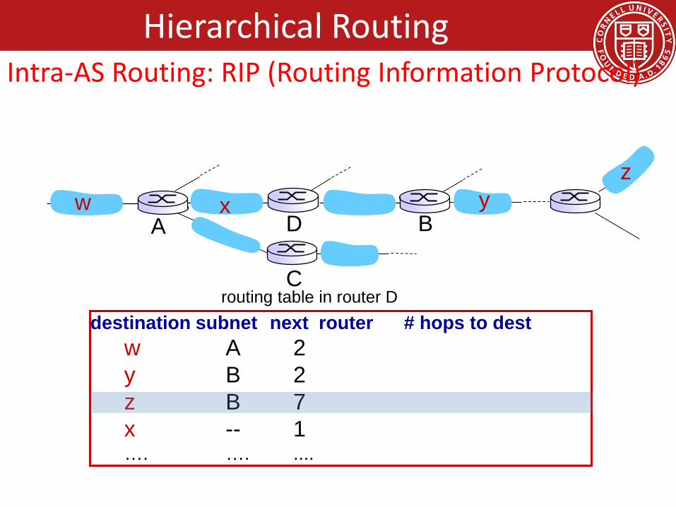
destination subnet next router # hops to destw A 2y B 2z B 7x -- 1…. …. ....
routing table in router D
w x yz
A
C
D B
Hierarchical RoutingIntra-AS Routing: RIP (Routing Information Protocol)

w x yz
A
C
D B
destination subnet next router # hops to destw A 2y B 2z B 7x -- 1…. …. ....
routing table in router D
A 5
dest next hopsw - 1x - 1z C 4…. … ...
A-to-D advertisement
Hierarchical RoutingIntra-AS Routing: RIP (Routing Information Protocol)

if no advertisement heard after 180 sec --> neighbor/link declared dead routes via neighbor invalidated new advertisements sent to neighbors neighbors in turn send out new advertisements (if
tables changed) link failure info quickly (?) propagates to entire net poison reverse used to prevent ping-pong loops
(infinite distance = 16 hops)
Hierarchical RoutingIntra-AS Routing: RIP—Link failure and recovery

RIP routing tables managed by application-levelprocess called route-d (daemon)advertisements sent in UDP packets, periodically
repeated
physicallink
network forwarding(IP) table
transport(UDP)
routed
physicallink
network(IP)
transprt(UDP)
routed
forwardingtable
Hierarchical RoutingIntra-AS Routing: RIP—Table processing

• “open”: publicly available• uses link state algorithm
– LS packet dissemination– topology map at each node– route computation using Dijkstra’s algorithm
• OSPF advertisement carries one entry per neighbor
• advertisements flooded to entire AS– carried in OSPF messages directly over IP (rather than
TCP or UDP• IS-IS routing protocol: nearly identical to OSPF
Intra-AS Routing: OSPF (Open Shortest Path First)Hierarchical Routing

• security: all OSPF messages authenticated (to prevent malicious intrusion)
• multiple same-cost paths allowed (only one path in RIP)
• for each link, multiple cost metrics for different TOS (e.g., satellite link cost set “low” for best effort ToS; high for real time ToS)
• integrated uni- and multicast support: – Multicast OSPF (MOSPF) uses same topology data
base as OSPF• hierarchical OSPF in large domains.
Intra-AS Routing: OSPF—Advanced features (not in RIP)Hierarchical Routing

boundary router
backbone router
area 1area 2
area 3
backboneareaborderrouters
internalrouters
Intra-AS Routing: Hiearchical OSPFHierarchical Routing
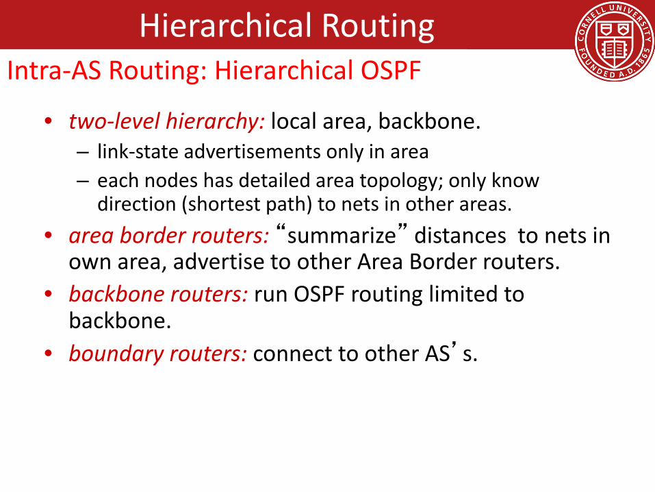
• two-level hierarchy: local area, backbone.– link-state advertisements only in area – each nodes has detailed area topology; only know
direction (shortest path) to nets in other areas.• area border routers: “summarize” distances to nets in
own area, advertise to other Area Border routers.• backbone routers: run OSPF routing limited to
backbone.• boundary routers: connect to other AS’s.
Intra-AS Routing: Hierarchical OSPFHierarchical Routing

Hierarchical Routing
• BGP (Border Gateway Protocol): the de facto inter-domain routing protocol– “glue that holds the Internet together”
• BGP provides each AS a means to:– eBGP: obtain subnet reachability information from
neighboring ASs.– iBGP: propagate reachability information to all AS-
internal routers.– determine “good” routes to other networks based
on reachability information and policy.• allows subnet to advertise its existence to rest
of Internet: “I am here”
Inter-AS Routing—BGP

when AS3 advertises a prefix to AS1: AS3 promises it will forward datagrams towards that prefix AS3 can aggregate prefixes in its advertisement
AS3
AS2
3b
3c3a
AS1
1c1a
1d1b
2a2c
2bothernetworks
othernetworks
BGP session: two BGP routers (“peers”) exchange BGP messages: advertising paths to different destination network prefixes (“path vector”
protocol) exchanged over semi-permanent TCP connections
BGP message
Hierarchical RoutingInter-AS Routing—BGP

AS3
AS2
3b3a
AS1
1c1a
1d1b
2a2c
2bothernetworks
othernetworks
using eBGP session between 3a and 1c, AS3 sends prefix reachability info to AS1. 1c can then use iBGP do distribute new prefix info to all routers in AS1 1b can then re-advertise new reachability info to AS2 over 1b-to-2a
eBGP session when router learns of new prefix, it creates entry for prefix in
its forwarding table.
eBGP session
iBGP session
Hierarchical RoutingInter-AS Routing—BGP distributing path information

• advertised prefix includes BGP attributes – prefix + attributes = “route”
• two important attributes:– AS-PATH: contains ASs through which prefix advertisement
has passed: e.g., AS 67, AS 17 – NEXT-HOP: indicates specific internal-AS router to next-
hop AS. (may be multiple links from current AS to next-hop-AS)
• gateway router receiving route advertisement uses import policy to accept/decline– e.g., never route through AS x– policy-based routing
Hierarchical RoutingInter-AS Routing—BGP routes and Path attributes

router may learn about more than 1 route to destination AS, selects route based on:
1. local preference value attribute: policy decision
2. shortest AS-PATH 3. closest NEXT-HOP router: hot potato routing4. additional criteria
Hierarchical RoutingInter-AS Routing—BGP Route Selection
BGP messages exchanged between peers over TCP connection BGP messages:
OPEN: opens TCP connection to peer and authenticates sender UPDATE: advertises new path (or withdraws old) KEEPALIVE: keeps connection alive in absence of
UPDATES; also ACKs OPEN request NOTIFICATION: reports errors in previous msg;
also used to close connection
Hierarchical RoutingInter-AS Routing—BGP Messages

A,B,C are provider networks X,W,Y are customer (of provider networks) X is dual-homed: attached to two networks X does not want to route from B via X to C .. so X will not advertise to B a route to C
A
B
C
WX
Y
legend:
customer network:
providernetwork
Hierarchical RoutingInter-AS Routing—BGP Routing Policy

A advertises path AW to B B advertises path BAW to X Should B advertise path BAW to C?
No way! B gets no “revenue” for routing CBAW since neither W nor C are B’s customers
B wants to force C to route to w via A B wants to route only to/from its customers!
A
B
C
WX
Y
legend:
customer network:
providernetwork
Hierarchical RoutingInter-AS Routing—BGP Routing Policy
policy: inter-AS: admin wants control over how its traffic
routed, who routes through its net. intra-AS: single admin, so no policy decisions neededscale:hierarchical routing saves table size, reduced update
trafficperformance: intra-AS: can focus on performance inter-AS: policy may dominate over performance
Hierarchical RoutingIntra- vs Inter-AS Routing


