

1
Network Testing and Commission Standards
Prepared by Field Practices
1

Document Title: Network Testing and Commissioning Standards Issue Date: Document Number: CS10# 1897047 © Horizon Power User to check printed document is correct
HORIZON POWER
DOCUMENT CONTROL
Document Owner (May also be the Process Owner)
Name: Mark Van Vuuren
Position: Field Practices Coordinator
Date: January 2014
Approved By * Name: Mark Van Vuuren
Position: Field Practices Coordinator
Date: January 2014
Authorisation ** Process Owner is hereby vested with authority and responsibility to manage the process end to end.
Name: Lance Roberts
Position: Manager Safety and Health
Date: January 2014
Date Created January 2010
Last Updated January 2014
Review Frequency *** Every 3 years
Next Review Date *** January 2019
* Must be the Process Owner and is the person assigned authority and responsibility for managing the whole process, end-to-end, which may extend across more than one division and/or functions, in order to deliver agreed business results.
** This person will have the power to grant the process owner the authority and responsibility to manage the process from end to end.
*** Frequency period is dependent upon circumstances– maximum is 5 years from last issue, review, or revision whichever is the latest. If left blank, the default will be 1 year unless otherwise specified.
STAKEHOLDERS
The following positions must be consulted if an update or review is required:
NOTIFICATION LIST
The following positions must be notified of any authorised change:

Page-ii
Document Title: Network Testing and Commissioning Standards Issue Date: Document Number: CS10# 1897047 © Horizon Power User to check printed document is correct
HORIZON POWER
Important Notice to Users
This manual has been developed for use by Horizon Power employees’ and Service Providers engaged to perform Network Testing and Commissioning Standards on Horizon Power Electrical Networks.
It is issued as a controlled document by Horizon Power to Horizon Power employees’ and Service Providers on the condition that it will only be used whilst undertaking Network Testing and Commissioning Standards on Horizon Power electricity distribution network.
Network Testing and Commissioning Standards will only be performed by individuals who are appropriately trained and qualified in accordance with accepted standards within Horizon Power. This Manual is not intended, and should not in any way be relied upon, as a substitute for such training.
Copyright 2007
Copyright is owned by Horizon Power.
Horizon Power (ACN 57 955 011 697).
All rights reserved. No part of this work may be reproduced or copied in any form or by any means (graphic, electronic, taping or information retrieval system) without the written permission of the copyright owner.
Table of Contents Page 3
Document Title: Network Testing and Commissioning Standards Issue Date: Document Number: CS10# 1897047 © Horizon Power User to check printed document is correct
HORIZON POWER
Table of Contents
Section Page Number
1. PURPOSE ............................................................................ 1-1
2. APPLICATION...................................................................... 2-1
2.1 GENERAL ......................................................................................... 2-1
2.2 PHILOSOPHY ..................................................................................... 2-1
2.3 RESPONSIBLE PERSONS .................................................................... 2-1
2.4 FORMAT ........................................................................................... 2-1
2.5 WORK FLOW ..................................................................................... 2-1
3. DEFINITIONS ....................................................................... 3-1
3.1 GENERAL ......................................................................................... 3-1
3.2 ABBREVIATIONS AND ACRONYMS ........................................................ 3-2
3.3 RELATED INFORMATION ..................................................................... 3-3
4. SAFETY AND WORK SKILLS ............................................. 4-1
4.1 GENERAL ......................................................................................... 4-1
4.2 RESPONSIBLE PERSONS .................................................................... 4-1
4.3 DUTY OF CARE ................................................................................. 4-2
5. AERIAL AND POLE-MOUNTED INSTALLATIONS ............. 5-1
5.1 POLE-TOP DISTRIBUTION TRANSFORMERS .......................................... 5-1
5.1.1 Purpose .............................................................................. 5-1
5.1.2 Related Information ............................................................ 5-1
5.1.3 Equipment Pre-Handover Status ........................................ 5-1
5.1.4 Pre-Commissioning Checks ................................................ 5-1
5.1.5 Commissioning the Equipment ........................................... 5-2
5.2 POLE-TOP SWITCHES AND DISCONNECTS ........................................... 5-3
5.2.1 Purpose .............................................................................. 5-3
5.2.2 Related Information ............................................................ 5-3
5.2.3 Equipment Pre-Handover Status ........................................ 5-3
5.2.4 Pre-Commissioning Checks ................................................ 5-3
5.2.5 Commissioning the Equipment ........................................... 5-4
5.3 HIGH VOLTAGE OVERHEAD CONDUCTOR ............................................ 5-4

Table of Contents Page 4
Document Title: Network Testing and Commissioning Standards Issue Date: Document Number: CS10# 1897047 © Horizon Power User to check printed document is correct
HORIZON POWER
5.3.1 Purpose .............................................................................. 5-4
5.3.2 Related Information ............................................................ 5-4
5.3.3 Equipment Pre-Handover Status ........................................ 5-4
5.3.4 Pre-Commissioning Checks ................................................ 5-5
5.3.5 Commissioning the Equipment ........................................... 5-5
5.4 LOW VOLTAGE OVERHEAD CONDUCTOR ............................................. 5-5
5.4.1 Purpose .............................................................................. 5-5
5.4.2 Related Information ............................................................ 5-6
5.4.3 Equipment Pre-Handover Status ........................................ 5-6
5.4.4 Pre-Commissioning Checks ................................................ 5-6
5.4.5 Commissioning the Equipment ........................................... 5-6
5.5 LOW VOLTAGE AERIAL BUNDLED CONDUCTOR .................................... 5-6
5.5.1 Purpose .............................................................................. 5-6
5.5.2 Related Information ............................................................ 5-7
5.5.3 Equipment Pre-Handover Status ........................................ 5-7
5.5.4 Pre-Commissioning Checks ................................................ 5-7
5.5.5 Commissioning the Equipment ........................................... 5-7
6. UNDERGROUND AND GROUND-MOUNT INSTALLATIONS6-1
6.1 GROUND-MOUNT/ PAD-MOUNT DISTRIBUTION TRANSFORMERS ............. 6-1
6.1.1 Purpose .............................................................................. 6-1
6.1.2 Related Information ............................................................ 6-1
6.1.3 Equipment Pre-Handover Status ........................................ 6-1
6.1.4 Pre-Commissioning Status ................................................. 6-2
6.1.5 Commissioning the Equipment ........................................... 6-3
6.2 HIGH VOLTAGE SWITCHGEAR ............................................................. 6-4
6.2.1 Purpose .............................................................................. 6-4
Note: To ensure that adequate point to point testing is maintained, a level 5 Switching Operator and a competent Recipient in Charge to assist, shall be used to commission any new RMUs onto the network. .............................................................................. 6-4
6.2.2 Related Information ............................................................ 6-5
6.2.3 Equipment Pre-Handover Status ........................................ 6-5
6.2.4 Pre-Commissioning Checks ................................................ 6-5
6.2.5 Commissioning the Equipment ........................................... 6-7
6.3 LOW VOLTAGE SWITCHGEAR.............................................................. 6-8
6.3.1 Purpose .............................................................................. 6-8
Table of Contents Page 5
Document Title: Network Testing and Commissioning Standards Issue Date: Document Number: CS10# 1897047 © Horizon Power User to check printed document is correct
HORIZON POWER
6.3.2 Related Information ............................................................ 6-8
6.3.3 Equipment Pre-Handover Status ........................................ 6-8
6.3.4 Pre-Commissioning Checks ................................................ 6-9
6.3.5 Commissioning the Equipment ........................................... 6-9
6.4 LOW VOLTAGE CABLES & PILLARS ................................................... 6-10
6.4.1 Purpose ............................................................................ 6-10
6.4.2 Related Information .......................................................... 6-10
6.4.3 Equipment Pre-Handover Status ...................................... 6-10
6.4.4 Pre-Commissioning Checks .............................................. 6-10
6.4.5 Commissioning the Equipment ......................................... 6-10
6.5 HIGH VOLTAGE CABLES ................................................................... 6-11
6.5.1 Purpose ............................................................................ 6-11
6.5.2 Related Information .......................................................... 6-11
6.5.3 Equipment Pre-Handover Status ...................................... 6-11
6.5.4 Pre-Commissioning Checks .............................................. 6-11
6.5.5 Commissioning the Equipment ......................................... 6-12
7. CUSTOMER OWNED INSTALLATIONS ............................. 7-1
7.1 DISTRIBUTION SUBSTATIONS .............................................................. 7-1
7.1.1 General ............................................................................... 7-1
7.1.2 Related Information ............................................................ 7-1
7.1.3 Requirements ..................................................................... 7-1
7.2 PRIVATE PARALLEL GENERATORS ...................................................... 7-1
7.2.1 General ............................................................................... 7-1
7.2.2 Related Information ............................................................ 7-2
7.2.3 Requirements ..................................................................... 7-2
8. SCADA AND COMMUNICATIONS INSTALLATION & COMMISSIONING ................................................................ 8-1
8.1 DISTRIBUTION SUBSTATIONS .............................................................. 8-1
8.2 RECLOSERS...................................................................................... 8-1
8.2.1 General ............................................................................... 8-1
8.2.2 Requirements ..................................................................... 8-1
8.2.3 Commissioning Instructions ................................................ 8-1
8.3 FAULT INDICATORS ............................................................................ 8-3
8.3.1 General ............................................................................... 8-3
8.3.2 Requirements ..................................................................... 8-3

Table of Contents Page 6
Document Title: Network Testing and Commissioning Standards Issue Date: Document Number: CS10# 1897047 © Horizon Power User to check printed document is correct
HORIZON POWER
8.3.3 Commissioning Instructions ................................................ 8-3
9. TESTING REQUIREMENTS ................................................. 9-7
9.1 LOW VOLTAGE XLPE CABLE TESTING ................................................ 9-7
9.1.1 Purpose .............................................................................. 9-7
9.1.2 Scope.................................................................................. 9-7
9.1.3 References ......................................................................... 9-7
9.1.4 Responsible Persons .......................................................... 9-8
9.1.5 Test Equipment ................................................................... 9-8
9.1.6 Instructions ......................................................................... 9-8
9.1.7 Tests ................................................................................... 9-8
9.1.8 Testing Schedule ................................................................ 9-9
9.2 LV CONTINUITY AND PHASING TESTING ............................................ 9-10
9.2.1 Purpose ............................................................................ 9-10
9.2.2 Scope................................................................................ 9-10
9.2.3 References, DCT-LV Cables with or without Pillars CS10# 2734124 ........................................................................... 9-10
9.2.4 Responsible Persons ........................................................ 9-10
9.2.5 Test Equipment ................................................................. 9-10
9.2.6 Instructions ....................................................................... 9-10
9.2.7 Testing Schedule .............................................................. 9-10
9.3 LOW VOLTAGE CABLE TESTING AFTER REPAIR .................................. 9-12
9.3.1 Purpose ............................................................................ 9-12
9.3.2 Test Equipment ................................................................. 9-12
9.3.3 Instructions – General ....................................................... 9-12
9.4 HIGH VOLTAGE XLPE CABLE TESTING ............................................. 9-14
9.4.1 Purpose ............................................................................ 9-14
9.4.2 Scope................................................................................ 9-14
9.4.3 References ....................................................................... 9-14
9.4.4 Responsible Persons ........................................................ 9-14
9.4.5 Test Equipment ................................................................. 9-14
9.4.6 Instructions ....................................................................... 9-14
9.4.7 Tests ................................................................................. 9-15
9.4.8 Testing Schedule .............................................................. 9-15
9.5 HIGH VOLTAGE PAPER INSULATED CABLE TESTING ........................... 9-16
9.5.1 Purpose ............................................................................ 9-16
Table of Contents Page 7
Document Title: Network Testing and Commissioning Standards Issue Date: Document Number: CS10# 1897047 © Horizon Power User to check printed document is correct
HORIZON POWER
9.5.2 Scope................................................................................ 9-16
9.5.3 References, DCT-HV PILC Screened Cables CS10# 2733834 ......................................................................................... 9-16
9.5.4 Responsible Persons ........................................................ 9-16
9.5.5 Test Equipment ................................................................. 9-16
9.5.6 Instructions ....................................................................... 9-17
9.5.7 Testing Schedule .............................................................. 9-19
9.6 HIGH VOLTAGE MIXED CABLE TESTING ............................................. 9-21
9.6.1 Purpose ............................................................................ 9-21
9.6.2 Scope................................................................................ 9-21
9.6.3 References ....................................................................... 9-21
9.6.4 Responsible Persons ........................................................ 9-21
9.6.5 Test Equipment ................................................................. 9-21
9.6.6 Instructions ....................................................................... 9-21
9.6.7 Tests ................................................................................. 9-22
9.6.8 Testing Schedule .............................................................. 9-22
9.7 HIGH VOLTAGE CABLE TESTING AFTER REPAIR OF OBVIOUS FAULT .... 9-23
9.7.1 Purpose ............................................................................ 9-23
9.7.2 Definitions ......................................................................... 9-23
9.7.3 Test Equipment ................................................................. 9-23
9.7.4 Test Procedure ................................................................. 9-24
9.8 EARTH TESTING .............................................................................. 9-25
9.8.1 Purpose ............................................................................ 9-25
9.8.2 Scope................................................................................ 9-25
9.8.3 References ....................................................................... 9-25
9.8.4 Responsible Persons ........................................................ 9-25
9.8.5 Test Equipment ................................................................. 9-25
9.8.6 Instructions ....................................................................... 9-25
9.8.7 Testing Schedule .............................................................. 9-26
9.9 LV SWITCHGEAR INSPECTION AND TESTING ...................................... 9-27
9.9.1 Purpose ............................................................................ 9-27
9.9.2 Scope................................................................................ 9-27
9.9.3 References ....................................................................... 9-27
9.9.4 Responsible Persons ........................................................ 9-27
9.9.5 Test Equipment ................................................................. 9-27
9.9.6 Instructions ....................................................................... 9-27

Table of Contents Page 8
Document Title: Network Testing and Commissioning Standards Issue Date: Document Number: CS10# 1897047 © Horizon Power User to check printed document is correct
HORIZON POWER
9.9.7 Tests ................................................................................. 9-28
9.10 HIGH VOLTAGE EXTENSIBLE SWITCHGEAR TESTING ........................... 9-29
9.10.1 Purpose ............................................................................ 9-29
9.10.2 Scope................................................................................ 9-29
9.10.3 References ....................................................................... 9-29
9.10.4 Responsible Persons ........................................................ 9-29
9.10.5 Test Equipment ................................................................. 9-29
9.10.6 Instructions ....................................................................... 9-29
9.10.7 Tests ................................................................................. 9-30
9.10.8 Testing Schedule .............................................................. 9-30
9.11 SUBSTATION DESIGN/INSTALLATION CHECK LIST ............................... 9-32
1. COMMON CONDITIONS .................................................... 9-32
PASS FAIL ............................................................................... 9-32
2. ADDITIONAL CONDITIONS WHERE SUBSTATION ENCLOSURE NOT REQUIRED ......................................... 2-33
3. ADDITIONAL CONDITIONS WHERE SUBSTATION ENCLOSURE REQUIRED .................................................. 3-34
SECTION 1 Page 1-1
Document Title: Network Testing and Commissioning Standards Issue Date: Document Number: CS10# 1897047 © Horizon Power User to check printed document is correct
HORIZON POWER
1. Purpose
The Technical Requirements therein provide the intent of the Testing & Commissioning Instructions set, and how these are applied to the testing and commissioning activities undertaken.
The Constructing Authority shall be responsible for ensuring that these Technical Requirements are met prior to and including hand-over to the Operating Authority.
SECTION 1 Page 1-2
Document Title: Network Testing and Commissioning Standards Issue Date: Document Number: CS10# 1897047 © Horizon Power User to check printed document is correct
HORIZON POWER
This Page Not Used.
SECTION 2 Page 2-1
Document Title: Network Testing and Commissioning Standards Issue Date: Document Number: CS10# 1897047 © Horizon Power User to check printed document is correct
HORIZON POWER
2. Application
2.1 General
These instructions apply to all work performed by persons subsequent to the hand-over of installed equipment through to final energisation on Horizon Powers electrical networks.
This standard recommends procedures and documentation to encourage safe working practices for the physical safety of persons in the above activities. The procedures considered necessary for the safe operation of the equipment and the interconnected network have also been included.
The objectives of this guide are to ensure the:-
1. safety of persons
2. continuity of supply
3. safeguard of electrical equipment
2.2 Philosophy
The documentation required for the activities described in this standard has been prepared as unique instructions. This does not preclude other documentation such as permits and tagging procedures which may be requirements of the Operating Authority and therefore are not explicitly identified here.
2.3 Responsible Persons
The Field Practices group shall be responsible for the issue of revisions to this standard. Information packages and presentations shall be prepared to promote changes on an as needs basis.
It is the responsibility of the individual involved in Testing & Commissioning activities to ensure they comprehend and understand the content of this Standard. It is the responsibility of the recipient to ensure they are in possession of the latest revision of this standard
2.4 Format
Instructions and procedures have been prepared and identified with a unique reference and revision detail. The revision number is an important record to ensure the reader is looking at the most current version, and allows others referencing to this instruction.
Fields not specifically identified in this standard are considered self-explanatory.
2.5 Work Flow
The workflow upon which this standard is based is detailed in the following responsibilities and flowchart.

SECTION 2 Page 2-2
Document Title: Network Testing and Commissioning Standards Issue Date: Document Number: CS10# 1897047 © Horizon Power User to check printed document is correct
HORIZON POWER
Project Manager advised of construction schedule
Installer advises Project Manager of construction timetable, so as routine inspections may be undertaken to monitor the quality of the installation.
Frequent / Planned inspections undertaken during construction
The Project Manager shall undertake routine inspections to monitor the quality of the workmanship, and advise of any corrective measures required.
Project Manager advised of testing schedule
Installer advises Project Manager of testing timetable, so as the testing may be witnessed by the Project Manager.
Project Manager Witnesses testing
The Project Manager shall undertake routine inspections to monitor the quality of the workmanship, and advise of any corrective measures required.
Project Manager issued with test certificates and completed schedules
Upon completion of the required testing, the Installer shall provide the Project Manager with relevant documentation.
Final inspection
A final inspection shall be undertaken of the site, to confirm that all connections have been reinstated, earths reapplied and equipment installation conforms to standards.
Underground Systems
If the interface to the existing network is via an underground system, the Installer shall undertake the interface work inclusive of cable jointing. This will require appropriate switching and permits to be issued by the Operating Authority.
Hand-over shall not be issued until the interface work is completed and tested.
Overhead Systems
If the interface to the existing network is via an overhead system, the interface work shall be undertaken by Horizon Power. At this point the Installer may hand-over the installation to Horizon Power.
Advise Operating Authority
The Operating Authority is required to be made aware of the need for switching and issue of permits. The scheduled time and date shall be made to meet the customer charter for the notification of supply interruption to be issued to surrounding customers as required.

SECTION 2 Page 2-3
Document Title: Network Testing and Commissioning Standards Issue Date: Document Number: CS10# 1897047 © Horizon Power User to check printed document is correct
HORIZON POWER
Notice of supply interruption
The notice of supply interruption is a requirement of Horizon Power’s customer charter, and the target shall be complied with where possible.
Interface work completed
The interface work is to be completed and tested by the responsible party.
Visual inspection undertaken
A final visual inspection shall be undertaken to confirm that the status of equipment is unchanged, cables are adequately protected, and no equipment is exposed to the public.
Hand-over of equipment
Hand-over may proceed when the Project Manager has accepted the work undertaken by the Construction Authority to his/her satisfaction in accordance with Horizon Power standards and guidelines.
The responsibility of the equipment is transferred to the Operating Authority of Horizon Power at this time.
Commissioning
The operating authority of Horizon Power will schedule and commission the equipment in accordance with the Switching Operators Manual and Horizon Power standards.
The work flow diagram for hand-over and commissioning of equipment is provided below.
SECTION 2 Page 2-4
Document Title: Network Testing and Commissioning Standards Issue Date: Document Number: CS10# 1897047 © Horizon Power User to check printed document is correct
HORIZON POWER
Project Manager advised of construction schedule
Frequent/Planned inspections undertaken during construction
Project Manager advised of testing schedule
Project Manager witnesses testing
Project Manager issued with test certificates and schedules
Advise Resource Centre, network interface requirements Scheduled (min 5 days lead time)
Notice of supply interruption served
o/h or u/g Interface?
Final site inspection, reinstatement of connections etc.
Overhead system
Interface work completed
Commissioning
Underground system
Handover of equipment
Advise Operating Authority, network interface requirements Scheduled (min 5 days lead time)
Notice of supply interruption served
Interface work completed
Commissioning
Visual inspection undertaken
Horizon Power Responsibility
Pre-Handover of equipment
Figure 1: Work Flow Diagram for Hand-Over & Commissioning Equipment

SECTION 3 Page 3-1
Document Title: Network Testing and Commissioning Standards Issue Date: Document Number: CS10# 1897047 © Horizon Power User to check printed document is correct
HORIZON POWER
3. Definitions
Throughout this standard, common terms of phrase and identification which may be unique to a workplace may have been used. It has not been the intention to create any ambiguity over responsibility and therefore a definition is provided for many of these terms below.
3.1 General
Installer
The authorised person responsible for the installation of equipment by the Construction Authority. This may be applied equally to Horizon Power as to the Property Developer.
Project Manager
The authorised person responsible for the management of the project including installation and handover tasks. This is also called the “Construction Project Manager” and is usually a field based person.
GIS Updater
The authorised person responsible for recording the details of the “as constructed” drawings in the Horizon Power Equipment databases. This includes the geographic representation (or map) in addition to the attribute data (or details) of the equipment.
Electrical equipment
Any equipment that is capable of being connected to a generating source or is associated with the supply of electricity.
Switch
A device designed and used for the making and breaking of an electric circuit.
High voltage
A voltage greaterr than;
1000 volts AC; or
1500 volts DC.
Low voltage
A voltage greater than;
32 volts and less than 1000 volts AC; or
115 volts and less than 1500 volts DC.

SECTION 3 Page 3-2
Document Title: Network Testing and Commissioning Standards Issue Date: Document Number: CS10# 1897047 © Horizon Power User to check printed document is correct
HORIZON POWER
Alive, live, energised
With reference to electrical apparatus shall mean that a voltage exists between apparatus and earth.
Isolated
Disconnected from all possible sources of electrical supply and needing deliberate planned physical movement to make apparatus alive.
De-energised
The electrical supply to electrical apparatus has been switched off but not: isolated and earthed (in case of high voltage supply), or isolated and short circuited (in case of low voltage supply)
Switching Operator
A person authorised by the Operating Authority to carry out switching operations to his/her level of authority
Hand-over Certificate
A certificate used to transfer responsibilities for any defined part of apparatus between the:
Construction Authority,
Commissioning Authority, or Operating Authority
Commissioning
The process by which new equipment is accepted energised by the Operating Authority.
Testing
The process in which the performance of the equipment is identified prior to the equipment becoming energised.
3.2 Abbreviations and Acronyms
AS Australian Standard
AS/NZS Australian Standard/New Zealand Standard
PVC Polyvinyl Chloride
WA Western Australia
HP Horizon Power
HPCC Horizon Power Control Centre

SECTION 3 Page 3-3
Document Title: Network Testing and Commissioning Standards Issue Date: Document Number: CS10# 1897047 © Horizon Power User to check printed document is correct
HORIZON POWER
3.3 Related Information
Perth One-Call System, operated by Association of Australia. Dial Before You Dig Services Ltd.
Western Australian Electrical Requirements (WAER) published by the WA Office of Energy.
Policy and Procedures for Contractor Safety published by Horizon Power.
Occupational Safety and Health Act 1984 published by the Governance of Western Australia.
Utility Providers Code of Practice for Western Australia published by Main Roads WA
AS/NZS 3000 Wiring Rules, published by Standards Australia
AS/NZS 1337 Eye Protectors for industrial application, published by published by Standards Australia
Underground Distribution Schemes Policy & Installations Options – Handbook for Developers DSB95/1 – Published by Horizon Power
Underground Distribution Schemes Policy & Installations Options – Substation Installation Requirements DSB95/6 – Published by Horizon Power
Electrical Instruction Standards Handbook – Published by Horizon Power
Western Australian Electrical Requirements – Published by Office of Energy
Switching Operators Manual - 1 – Published by Horizon Power
Testing of High Voltage Cables Manual – Published by Horizon Power

SECTION 3 Page 3-4
Document Title: Network Testing and Commissioning Standards Issue Date: Document Number: CS10# 1897047 © Horizon Power User to check printed document is correct
HORIZON POWER
This Page Not Used.

SECTION 4 Page 4-1
Document Title: Network Testing and Commissioning Standards Issue Date: Document Number: CS10# 1897047 © Horizon Power User to check printed document is correct
HORIZON POWER
4. Safety and Work Skills
4.1 General
Commissioning new electrical equipment has great potential for hazardous consequences and the need to consider safety at each step in the process cannot be stressed too highly.
The operator shall use safety equipment and wear all safety clothing required of the work.
All high voltage exposed conductors and electrical equipment must be regarded as alive until isolated, proved de-energised and earthed by approved means.
All low voltage exposed conductors and electrical equipment must be regarded as alive until isolated and proved de-energised and earthed by approved means.
The individual is responsible for keeping abreast of the content of these instructions.
4.2 Responsible Persons
A switching operator who undertakes commissioning of equipment must have an appropriate level of Horizon Power’s Switching Operator Authorisation. Common authority levels are listed below.
Level 1 Overhead low voltage system and High Voltage drop-out fuses
Level 2 Overhead High Voltage Systems
Level 3 Limited Underground High and Low Voltage Systems
Level 4 Concentrated Underground areas. Low Voltage System
Level 5 Concentrated Underground areas. High Voltage System
Level 6 Distributed feeders from zone substation. Field regulators
Level 7 Zone Substations transmission Lines
Level 8 Zone Substation
Level 9 Terminal Substation Regional Circuits
Level 10 Terminal Substation All Circuits
Switching Operator levels 7 to Level 10 (inclusive) do not apply to this standard.
SECTION 4 Page 4-2
Document Title: Network Testing and Commissioning Standards Issue Date: Document Number: CS10# 1897047 © Horizon Power User to check printed document is correct
HORIZON POWER
The required level of authority is managed by the Field Practices group.
The appropriate accreditation must be attained and recognised by the Asset Manager to undertake all Testing & Commissioning activities not explicitly covered by the above.
4.3 Duty of Care
Each individual has a duty of care to themselves, their co-workers, the public and employer when undertaking work. This means that the worker shall not engage in unapproved activities nor implement shortcuts while undertaking testing and commissioning activities.
An operator must not undertake activities beyond their designated training or authority.

SECTION 5 Page 5-1
Document Title: Network Testing and Commissioning Standards Issue Date: Document Number: CS10# 1897047 © Horizon Power User to check printed document is correct
HORIZON POWER
5. Aerial and Pole-Mounted Installations
The intention of this section is to provide details of the commissioning requirements of aerial or pole-mounted equipment. This section currently contains details of the following installation types;
5.1 Pole-Top Distribution Transformers
5.2 Pole-Top Switches & Disconnectors
5.3 High Voltage Overhead Conductor
5.4 Low Voltage Overhead Conductor
5.5 Low Voltage Aerial Bundled Conductor
5.1 Pole-Top Distribution Transformers
5.1.1 Purpose
This procedure provides guidelines for commissioning Pole-Top Distribution Transformers up to 315kva to verify that;
1. the equipment has not been damaged in transit
2. the equipment has been installed in the network correctly
3. the equipment operates to specification and is suitable for service
This procedure shall be operated in conjunction with the requirements of the Electrical Instruction Standards Handbook and the Switching Operators Manual – 1.
5.1.2 Related Information
None.
5.1.3 Equipment Pre-Handover Status
Transformers shall be installed in accordance with the appropriate guidelines, and as detailed in the Distribution Construction Standard Handbook HB1.
On completion, the Installer shall issue an earth testing schedule and hand-over certificate to the Operating Authority.
5.1.4 Pre-Commissioning Checks
The following list shall provide a checklist to be completed prior to any commissioning activities.
Check and comprehend the transformer hand-over certificate
Check the Earth testing schedule
Check the integrity of the transformer tank and assembly for oil leaks

SECTION 5 Page 5-2
Document Title: Network Testing and Commissioning Standards Issue Date: Document Number: CS10# 1897047 © Horizon Power User to check printed document is correct
HORIZON POWER
Check the transformer has been installed correctly and is suitable for service
For 315kVA, check to ensure there are two harnesses installed. Check cores have not been inadvertently crossed
Check there are no obstructions or hazards left for the public
Open all fuse-ways, LV disconnects
Check all neutral connections
Check all earth connections
Check all HV phase connections, including surge arrestors
5.1.5 Commissioning the Equipment
Prepare a commissioning program to energise the equipment in accordance with Switching Operators Manual - 1. Steps shall be included in the program to;
prove the connections to the LV mains are correct
measure the no-load secondary voltage of the transformer to ensure that it meets the statutory voltage requirements
check the phase rotation and synchronisation is correct
The commissioning should be set out in a switching programme, which includes the following steps
1. Check the LV disconnectors are open.
2. Close the drop-out fuses. (This allows the transformer to be energised from a remote point.)
3. Check the no load volts are at the transformer LV disconnects.
4. Phase out across the LV transformer disconnectors.
5. Close the LV transformer disconnects.
6. Open the LV interconnected disconnects, where applicable. If isolation for the work has been done, via a pole top switch instead of drop-out fuses, the pole top switch should be used for energising.
When new or reconstructed LV apparatus is erected, it must conform to the Horizon Power practices for the construction of distribution overhead lines.
The operator should phase out at an existing LV point, if possible where new LV disconnects has been fitted, they must be phased out and then checked for sound operation.
1. Carry out the commissioning program.
2. Check and record the final no-load voltage on each phase of the LV of the transformer.

SECTION 5 Page 5-3
Document Title: Network Testing and Commissioning Standards Issue Date: Document Number: CS10# 1897047 © Horizon Power User to check printed document is correct
HORIZON POWER
3. Check and record the final tap position of the transformer.
4. Replace the temporary cable-destination and transformer labels with permanent labels on the transformer as detailed in NS 05-2000 Distribution Equipment Labelling standard.
5. Complete a commissioning completion report and file in project file.
6. Send copy of commissioning report and relevant drawings to GIS Maps (Geographical Information Systems inbox) and Ellipse Equipment Register Records.
7. Ensure all equipment is in its final circuit condition and all normal open points are set to their designated position.
8. Ensure all equipment is locked, signposted and protected from unauthorized entry.
Ensure the work area is clean and tidy before leaving.
5.2 Pole-Top Switches and Disconnects
5.2.1 Purpose
This procedure provides guidelines for commissioning Pole-top switches and disconnects.
This procedure shall be operated in conjunction with the requirements of the Electrical Safety Standards Handbook, Switching Operators Manual - 1 and the switchgear manufacturers operating and commissioning instruction manual.
If a Transformer and Low Voltage Switchgear are to be commissioned at the same time as the Pole-Top Switch then it will be necessary to refer to the procedures for commissioning these items of equipment and include the appropriate switching operations in the switching program.
5.2.2 Related Information
None.
5.2.3 Equipment Pre-Handover Status
Pole-top switches and disconnects shall be installed in accordance with the appropriate guidelines, and as detailed in the Distribution Construction Standard Handbook HB1.
On completion, the Installer shall issue an earth testing schedule and hand-over certificate to the Operating Authority.
5.2.4 Pre-Commissioning Checks
The following list shall provide a checklist to be completed prior to any commissioning activities.
1. Check and comprehend the hand-over certificate

SECTION 5 Page 5-4
Document Title: Network Testing and Commissioning Standards Issue Date: Document Number: CS10# 1897047 © Horizon Power User to check printed document is correct
HORIZON POWER
2. Check the Earth testing schedule
3. Check the integrity of the switch, mechanism and handle. The operation of the pole top switch must be checked to make sure that the three contacts are firm and made simultaneously
4. Check the integrity of the earth mat, connections and inspection pit
5. Affix temporary labels. Before the switch is put into operation it must be labelled with an individual identity number.
5.2.5 Commissioning the Equipment
1. Carry out the commissioning program.
2. Replace the temporary labels with permanent labels.
3. Complete a commissioning completion report and file in project file.
4. Send copy of commissioning report and relevant drawings to GIS Maps (Geographical Information Systems inbox) and Ellipse Equipment Register Records.
5. Ensure all equipment is in its final circuit condition and all normal open points are set to their designated position.
6. Ensure all equipment is locked, signposted and protected from unauthorised access.
Ensure the work area is clean and tidy before leaving.
5.3 High Voltage Overhead Conductor
5.3.1 Purpose
This procedure provides guidelines for commissioning of High Voltage Overhead Conductor.
This procedure shall be operated in conjunction with the requirements of the Electrical Instruction Standards Handbook, Switching Operators Manual - 1 and the switchgear manufacturers operating and commissioning instruction manual.
5.3.2 Related Information
None.
5.3.3 Equipment Pre-Handover Status
High Voltage Overhead conductor shall be installed in accordance with the appropriate guidelines, and as detailed in the Distribution Construction Standard Handbook HB1.
Where down earths are provided for the system earth or earth wire installed, an earth testing schedule and hand-over certificate shall be issued to the Operating Authority by the Installer.

SECTION 5 Page 5-5
Document Title: Network Testing and Commissioning Standards Issue Date: Document Number: CS10# 1897047 © Horizon Power User to check printed document is correct
HORIZON POWER
5.3.4 Pre-Commissioning Checks
The following list shall provide a checklist to be completed prior to any commissioning activities.
1. Check and comprehend the hand-over certificate
2. Check the Earth testing schedule
3. Check the installed earths, connections and inspection pit
5.3.5 Commissioning the Equipment
The following steps should be carried out with the switch in the energised state.
1. Carry out the commissioning program which will include the following steps:
Set the auto-reclose on the HV feeders either side of the switch to MANUAL.
Using a correctly rated HV phasing stick, phase out across all three phases.
If required, close the switch – otherwise leave in open position. Lock switch handle.
Set the auto-reclose on the HV feeders back to AUTO.
2. Replace the temporary labels with permanent labels.
3. Complete a commissioning completion report and file in project file.
4. Send copy of commissioning report and relevant “As Constructed Drawings” GIS (Geographical Information Systems inbox) Updater for updating GIS Maps and Ellipse Equipment Register Records.
5. Make sure that all three contacts are firm and make contact simultaneously.
6. Ensure all equipment is in its final circuit condition and all normal open points are set to their designated position.
7. Ensure all equipment is locked, signposted and protected from unauthorised access.
8. Ensure the work area is clean and tidy before leaving
5.4 Low Voltage Overhead Conductor
5.4.1 Purpose
This procedure provides guidelines for commissioning of Low Voltage Overhead Conductor.
This procedure shall be operated in conjunction with the requirements of the Electrical Instruction Standards Handbook, Switching Operators
SECTION 5 Page 5-6
Document Title: Network Testing and Commissioning Standards Issue Date: Document Number: CS10# 1897047 © Horizon Power User to check printed document is correct
HORIZON POWER
Manual - 1 and the switchgear manufacturers operating and commissioning instruction manual.
5.4.2 Related Information
DCT-LV Overhead Lines CS10# 273349
5.4.3 Equipment Pre-Handover Status
Low Voltage Overhead conductor shall be installed in accordance with the appropriate guidelines, and as detailed in the Distribution Construction Standard Handbook HB1 and/or approved design drawing.
5.4.4 Pre-Commissioning Checks
The following checklist shall be completed prior to any commissioning activities.
1. Check and comprehend the hand-over certificate.
2. Check that the GIS Pick ID (Ellipse Plant) numbers for each item are in accordance with the “as constructed drawings”.
3. Check all line taps are correctly placed and are secure.
4. Check for correct neutral and phase conductor arrangement.
5.4.5 Commissioning the Equipment
1. Carry out the commissioning program in accordance with Switching Operators Manual – 1.
2. Phase out at an existing LV point if possible.
3. Where new LV disconnects has been installed, they must be phased out and checked.
4. Complete a commissioning completion report and file in project file.
5. Send copy of commissioning report and relevant drawings to GIS Maps (Geographical Information Systems inbox) and Ellipse Equipment Register Records.
6. Ensure all equipment is in its final circuit condition and all normal open points are set to their designated position.
7. Ensure all equipment is locked, signposted and protected from unauthorised access.
8. Ensure the work area is clean and tidy before leaving.
5.5 Low Voltage Aerial Bundled Conductor
5.5.1 Purpose
This procedure provides guidelines for commissioning of Low Voltage Aerial Bundled Conductor.
SECTION 5 Page 5-7
Document Title: Network Testing and Commissioning Standards Issue Date: Document Number: CS10# 1897047 © Horizon Power User to check printed document is correct
HORIZON POWER
This procedure shall be operated in conjunction with the requirements of the Electrical Instruction Standards Handbook, Switching Operators Manual - 1 and the switchgear manufacturers operating and commissioning instruction manual.
5.5.2 Related Information
DCT-LV Aerial Bundled Conductor CS10# 2734391
5.5.3 Equipment Pre-Handover Status
Low Voltage Aerial Bundled conductor shall be installed in accordance with the appropriate guidelines, and as detailed in the Distribution Construction Standard Handbook HB1.
5.5.4 Pre-Commissioning Checks
The following list shall provide a checklist to be completed prior to any commissioning activities.
1. Check and comprehend the hand-over certificate.
2. Check that the GIS Updater has generated the GIS Pick ID numbers for each item in accordance with the construction drawings.
3. Check the correct fuse size.
4. Check correct design tension
5.5.5 Commissioning the Equipment
1. Carry out the commissioning program in accordance with Switching Operators Manual - 1
2. Complete a commissioning completion report and file in project file.
3. Send copy of commissioning report and relevant drawings to GIS (Geographical Information Systems inbox) Updater for updating GIS Maps and Ellipse Equipment Register Records.
4. Ensure all equipment is in its final circuit condition and all normal open points are set to their designated position.
5. Ensure all equipment is locked, signposted and protected from unauthorised access.
6. Ensure the work area is clean and tidy before leaving.

SECTION 6 Page 6-1
Document Title: Network Testing and Commissioning Standards Issue Date: Document Number: CS10# 1897047 © Horizon Power User to check printed document is correct
HORIZON POWER
6. Underground and Ground-mount Installations
The intention of this section is to provide details of the commissioning requirements of underground or ground-mount equipment. This section currently contains details of the following installation types;
6.1 Ground-mount Distribution Transformers
6.2 High Voltage Switchgear
6.3 Low Voltage Switchgear
6.4 Low Voltage Cables & Pillars
6.5 High Voltage Cables
6.6 Low Voltage Cables
6.1 Ground-mount/ Pad-mount Distribution Transformers
6.1.1 Purpose
This procedure provides guidelines for commissioning Ground Mounted Distribution Transformers up to 1000kVA to verify that;
the equipment has not been damaged in transit
the equipment has been installed in the network correctly
the equipment operates to specification and is suitable for service
This procedure shall be operated in conjunction with the requirements of the Electrical Instruction Standards Handbook and the Switching Operators Manual - 1
6.1.2 Related Information
None.
6.1.3 Equipment Pre-Handover Status
Distribution Transformers
Distribution transformers shall be installed in accordance with the appropriate guidelines and as detailed in the Underground Distribution Systems Policy and Installations Options Manual.
On completion a Earthing testing schedule and handover certificate shall be issued to the Project Manager by the Installer.
Underground Cable
The cable links between the High Voltage ring main switchgear, the transformer and the Low Voltage switchgear shall be installed, terminated and jointed in accordance with the appropriate standards and guidelines as documented in the Underground Distribution Systems Policy and Installations Options Manual.
SECTION 6 Page 6-2
Document Title: Network Testing and Commissioning Standards Issue Date: Document Number: CS10# 1897047 © Horizon Power User to check printed document is correct
HORIZON POWER
The Installer shall fix temporary labels to the transformer(s) and switch fuse unit(s) stating the destinations of all cables (as minimum, more permanent labels may be fitted at this time).
Insulation, continuity and phasing tests shall be carried out and the results recorded.
On completion, the Installer shall issue High Voltage and Low Voltage cable testing schedules in addition to the handover certificate to the Operating Authority.
6.1.4 Pre-Commissioning Status
The following checks are to be completed prior to any commissioning activities.
1. Go to site and verify that the equipment has been installed correctly and is suitable for service.
2. Check and comprehend the transformer handover certificate
3. Check and comprehend the cable handover certificate. Note: In most cases a combined handover certificate will be issued for the transformer and cables.
4. If the cable is to be laid by the customer, then prior to the handover to HP to carry out the jointing, a pre-acceptance test (Insulation Resistance Test) must be carried out on the cable to determine the state of the cable.
5. Check that the Earth grid is installed as required in the Distribution Substation Manual
6. Check all Earth connections to the transformer
7. Check the Earth testing schedule (refer to section 9.6)
8. Check the HV cable testing schedule
9. Check the LV cable testing schedule
10. Check that the GIS Pick ID (Ellipse Plant) numbers for each item are in accordance with the “as constructed drawings”.
11. Prepare permanent cable destination labels in accordance with NS 05-2000 Distribution Equipment Labelling standards.
12. Go to site and use the “Substation Installation Check List” form to verify that the equipment has been installed correctly and is suitable for service as per the design drawing.
13. Check the integrity of the transformer tank and assembly for oil leaks.
14. Check that un-used bushings are fitted with proper bushing inserts and

SECTION 6 Page 6-3
Document Title: Network Testing and Commissioning Standards Issue Date: Document Number: CS10# 1897047 © Horizon Power User to check printed document is correct
HORIZON POWER
are correctly capped.
Note: DO NOT confuse with caps fitted from factory since these are NOT rated.
15. Check that drain wires are connected to all HV elbow connectors and connected to cable screen.
16. Note: This ensures the elbows are safe to touch.
17. Check HV screens are all solidly and separately bolted to the HV earth bar.
18. Check all elbow connectors are fitted with correct bailing assemblies and are secure.
19. For new MPS and NON-MPS transformer installations, Visually check that ALL phase and Earth/Neutral connections are securely bolted.
20. For MPS and NON-MPS transformer changeovers that occur, once the new transformer is installed, and while the kiosk is still removed Visually & Physically check that ALL phase connections have been reconnected to the correct bushings. Once a team member has completed this step, a second team member shall complete this step again to confirm the connections.
21. For pad mount transformers in car parks, ensure bollards are installed around the pad mount transformer.
22. If the transformer is for the sole use of a single customer and has multiple LV single core cables on each phase, check that none of the cores have been inadvertently crossed between phases otherwise a short circuit of the transformer will occur when the equipment is energised.
23. Check that there are no cables exposed to the public and backfill if required.
24. Check site for erosion around transformer. If so, then backfill with blue metal or crushed limestone.
25. Open all LV fuse-ways, including the transformer disconnect.
26. Check all LV neutral connections are connected to the LV neutral bar, not the earth bar.
27. Check the transformer is set to the correct HV tap setting.
6.1.5 Commissioning the Equipment
1. Prepare a commissioning program to energise the equipment in accordance with Switching Operators Manual - 1. Steps shall be included in the program to;

SECTION 6 Page 6-4
Document Title: Network Testing and Commissioning Standards Issue Date: Document Number: CS10# 1897047 © Horizon Power User to check printed document is correct
HORIZON POWER
Prove that the temporary cable destination and transformer labels are correct
Measure the no load secondary voltage of the transformer to ensure that it meets the statutory voltage requirements
Check that the phase rotation and synchronisation is correct
Note: The commissioning program for the transformer may be incorporated into the commissioning program for the Ring Main Switchgear.
2. Carry out the commissioning program.
3. Check and record the final no-load voltage on each phase of the LV of the transformer.
4. Check and record the final tap position of the transformer.
5. Replace the temporary cable-destination and transformer labels with permanent labels on the transformer as detailed in NS 05-2000 Distribution Equipment Labelling standard.
6. Complete a commissioning completion report and file in project file.
7. Send copy of commissioning report and relevant drawings to GIS (Geographical Information Systems inbox) Updater for updating GIS Maps and Ellipse Equipment Register Records.
8. Ensure all equipment is in its final circuit condition and all normal open points are set to their designated position.
9. Ensure all equipment is locked, signposted and protected from unauthorised entry.
10. Ensure the work area is clean and tidy before leaving.
6.2 High Voltage Switchgear
6.2.1 Purpose
This procedure provides guidelines for commissioning High Voltage Ring Main Switchgear to verify that, the equipment has not been damaged in transit, and the equipment has been installed in the network correctly.
Note: To ensure that adequate point to point testing is maintained, a level 5 Switching Operator and a competent Recipient in Charge to assist, shall be used to commission any new RMUs onto the network.
This procedure shall be operated in conjunction with the requirements of the Electrical Instruction Standards Handbook, Switching Operators Manual - 1 and the switchgear manufacturers operating and commissioning instruction manual.
If a Transformer and Low Voltage Switchgear are to be commissioned at the same time as the Ring Main Switchgear then it will be necessary to

SECTION 6 Page 6-5
Document Title: Network Testing and Commissioning Standards Issue Date: Document Number: CS10# 1897047 © Horizon Power User to check printed document is correct
HORIZON POWER
refer to the procedures for commissioning these items of equipment and include the appropriate switching operations in the switching program.
6.2.2 Related Information
Australian Standard AS 2067 Switchgear assemblies and ancillary equipment – Published by Standards Australia
Australian Standard AS 2650 High Voltage ac switchgear and control gear – Common Requirements – Published by Standards Australia
6.2.3 Equipment Pre-Handover Status
High Voltage Switchgear
The Ring Main Switchgear shall be installed in accordance with the appropriate standards and guidelines as documented in the Underground Distribution Systems Policy and Installations Options Manual.
Where extensible switchgear has been assembled on site to form a composite type switchboard the Installer prior to terminating the cables shall test it to Australian Standards AS 2067 and AS 2650.
On completion a High Voltage switchgear testing schedule, the Installer shall issue Earthing testing schedule and a handover certificate to the Project Manager.
High Voltage Underground Cables
The cables shall be installed, terminated and jointed in accordance with the appropriate standards and guidelines and as detailed in the Underground Distribution Systems Policy and Installations Options Manual.
The Installer shall fix temporary labels to all switches stating the destinations of all cables.
Sheath and insulation tests shall be carried out and the results recorded.
On completion a High Voltage cable-testing schedule shall be provided in addition to the handover certificate and issued to the Project Manager by the Installer.
The equipment “as constructed” drawings must be prepared and issued prior to the Project manager accepting and signing off the handover certificate.
6.2.4 Pre-Commissioning Checks
1. The following checklist shall be completed prior to any commissioning activities.
2. Check and comprehend the handover certificate. Note: This should include the switchgear and connecting cable.

SECTION 6 Page 6-6
Document Title: Network Testing and Commissioning Standards Issue Date: Document Number: CS10# 1897047 © Horizon Power User to check printed document is correct
HORIZON POWER
3. Check the H.V. switchgear testing schedules as appropriate. Note: Non-extensible switchgear will not require additional on-site testing.
4. Check the H.V. cable testing schedule
5. Check the Earth testing schedule
6. Check that the GIS Pick ID (Ellipse Plant) numbers for each item of equipment are in accordance with the “as constructed drawings”.
7. Prepare a substation location label and permanent cable destination labels in accordance with NS 05-2000 Distribution Equipment labelling standard, if not already completed.
8. Consult the switchgear manufacturers operating & commissioning instruction manual to identify any items that must checked before the equipment is placed in service.
BEFORE PROCEEDING ENSURE THE CABLES EITHER SIDE OF THE HIGH VOLTAGE SWITCHGEAR ARE DE-ENERGISED.
9. Go to site and use the “Substation Installation Check List” form to verify that the equipment has been installed correctly and is suitable for service as per the design drawing.
10. Where appropriate, check the Gas Leakage Indication Gauge to verify that the switchgear has sufficient service pressure.
11. If a switch disconnect and/or fuse-switch is “spare” and does not have a cable connected then check that it is selected to the earth position and that it is appropriately tagged.
12. Spare units shall always be selected to the earth position.
13. Clean any dust, which may have blown onto the unit during the installation activities.
14. Check all HV cable terminations are secure and correct bailing assemblies are used.
15. Check that any un-used bushings are correctly capped using rated parts and bailing fitted.
16. Check drain wires are fitted to all HV elbow connectors and connected to cable screen. Note: This ensures the elbows are safe to touch.
17. Check the HV cable screens are all solidly and separately connected and bolted to the HV earth bar.
18. Ensure integrity of earthling system.

SECTION 6 Page 6-7
Document Title: Network Testing and Commissioning Standards Issue Date: Document Number: CS10# 1897047 © Horizon Power User to check printed document is correct
HORIZON POWER
19. Ensure switch disconnects are in the OFF position and fuse switches are OFF and in the EARTH position.
20. Install HRC fuses according to the design and ensure that the striker pin faces the striker bar. Note: Clean the inside of the fuse compartment of all visible dirt.
Switch the transformer fuse switch back to the OFF position.
6.2.5 Commissioning the Equipment
1. Prepare a switching program to energise the equipment in accordance with the current HPCC procedures and Switching Operators Manual - 1. Steps shall be included in the program to prove beyond doubt that:
All switches operate correctly.
Cable destination labels on all switches are correct.
Phase rotation and synchronisation is correct at all points of interconnection between the new and existing cables.
Note: An example of this process may be found in Switching Operators Manual - 1 (section 10.3)
Neon phase indicators (where fitted) are connected to the correct phases.
Note: Neon indicators must not be used for phasing out unless they have been individually commissioned during installation.
Where automation is provided, ensure that the SCADA labelling and operation is true and correct
2. Carry out the switching program.
3. Fit the substation location label as detailed in HPCC-9AF-07-0001-2011 Labelling Standard Distribution Equipment.
4. Complete a commissioning completion report for project file.
5. Send a copy of the commissioning report and relevant drawings to the GIS Updater to update the database. GIS (Geographical Information Systems inbox)
6. Send a system change request form to HPCC to update the HV schematics.
7. Ensure all equipment is in its final circuit condition and all normal open points are set to their designated position.
8. Ensure all equipment is locked, signposted and protected from unauthorised entry.
9. Ensure the work area is clean and tidy before leaving.

SECTION 6 Page 6-8
Document Title: Network Testing and Commissioning Standards Issue Date: Document Number: CS10# 1897047 © Horizon Power User to check printed document is correct
HORIZON POWER
6.3 Low Voltage Switchgear
6.3.1 Purpose
This procedure provides guidelines for commissioning Low Voltage Switchgear to verify that;
The equipment has not been damaged in transit
The equipment has been installed in the network correctly
This procedure shall be operated in conjunction with the requirements of the Electrical Instruction Standards Handbook, Switching Operators Manual - 1 and the switchgear manufacturers operating and commissioning instruction manual.
If a Transformer and Low Voltage Switchgear are to be commissioned at the same time as the Ring Main Switchgear then it will be necessary to refer to the procedures for commissioning these items of equipment and include the appropriate switching operations in the switching program.
6.3.2 Related Information
Australian Standard AS 3000-2000 Electrical Installations (known as Wiring Rules).
6.3.3 Equipment Pre-Handover Status
Low Voltage Switchgear
The Low Voltage Switchgear shall be installed in accordance with the appropriate standards and guidelines as documented in the Underground Distribution Systems Policy and Installations Options Manual.
On completion, the Installer shall issue a hand-over certificate to the Project Manager.
Low Voltage Underground Cable
The cables shall be installed, terminated and jointed in accordance with the appropriate standards and guidelines as detailed in the Underground Distribution Systems Policy and Installations Options Manual.
The Installer shall fix temporary labels to all fuse disconnector units stating the destinations of all cables (as a minimum, more permanent labels may be fitted at this time).
Insulation, continuity and phasing tests shall be carried out and the results recorded.
On completion a Low Voltage cable testing schedule, Low Voltage continuity & phasing schedule, earthing test schedule and a handover certificate shall be issued to the Project Manager by the Installer.

SECTION 6 Page 6-9
Document Title: Network Testing and Commissioning Standards Issue Date: Document Number: CS10# 1897047 © Horizon Power User to check printed document is correct
HORIZON POWER
6.3.4 Pre-Commissioning Checks
The following checklist shall be completed prior to any commissioning activities.
1. Check and comprehend the handover certificate.
Note: This should include the cables and switchgear.
2. Check the L.V. cable testing schedules.
3. Check that the GIS Pick ID numbers for each item are in accordance with the “as constructed drawings”.
4. Prepare permanent cable destination labels in accordance with NS 05-2000 Distribution Equipment Labelling standards.
5. If a fuse disconnect is “spare” and does not have a cable connected then check that it is appropriately tagged.
6. Ensure that any conditions mentioned in the Distribution Transformer pre-commissioning requirements are met.
6.3.5 Commissioning the Equipment
1. Prepare a commissioning program to energise the equipment in accordance with Switching Operators Manual - 1. Steps shall be included in the program to prove beyond doubt that:
temporary cable destination labels on all transformer and fuse disconnector units are correct
Phase rotation and synchronisation is correct at all points of interconnection between the new and existing cables.
2. Carry out the commissioning program.
3. Ensure that the HRC fuses installed on each cable circuit comply with the fuse capacity specified on the design drawing.
4. Replace the temporary cable destination labels with permanent labels on all transformers and fuse-disconnect units (if required).
5. Complete a commissioning completion report and file in the project file.
6. Send copy of commissioning report and relevant drawings to GIS (Geographical Information Systems inbox) Updater for updating GIS Maps and Ellipse Equipment Register Records.
7. Ensure all equipment is in its final circuit condition and all normal open points are set to their designated position.
8. Ensure all equipment is locked, signposted and protected from unauthorised entry.
9. Ensure the work area is clean and tidy before leaving.

SECTION 6 Page 6-10
Document Title: Network Testing and Commissioning Standards Issue Date: Document Number: CS10# 1897047 © Horizon Power User to check printed document is correct
HORIZON POWER
6.4 Low Voltage Cables & Pillars
6.4.1 Purpose
This procedure provides guidelines for commissioning Low Voltage Cables & Pillars
6.4.2 Related Information
None.
6.4.3 Equipment Pre-Handover Status
The cable shall be installed, terminated and jointed in accordance with the appropriate standards and guidelines as documented in the Underground Distribution Systems Policy and Installations Options Manual.
The Installer shall affix a label to the fused-switch of each circuit stating the destination of each cable.
Insulation, sheath integrity, continuity and phasing tests shall be carried out and the results recorded.
On completion, the Installer shall issue cable-testing schedules in addition to the handover certificate to the Operating Authority.
6.4.4 Pre-Commissioning Checks
The following list shall provide a checklist to be completed prior to any commissioning activities.
1. Check and comprehend the cable handover certificate.
2. Check the cable-testing schedule as well as the continuity and phasing testing schedule.
3. Prepare permanent cable identification labels in accordance with NS 05-2000 Distribution Equipment Labelling standards.
4. Check neutral screens are all solidly and separately bolted to the neutral bar.
5. Verify that all equipment has been installed correctly and is suitable for service.
6. Check that there are no cables exposed to the public and backfill if required.
6.4.5 Commissioning the Equipment
Correct work practices must also be observed for the commissioning of this apparatus.
1. All cables must be correctly connected, labelled, protected against mechanical damage, and saddled.
2. Feeder pillars, mini pillars and LV connection points should be fitted

SECTION 6 Page 6-11
Document Title: Network Testing and Commissioning Standards Issue Date: Document Number: CS10# 1897047 © Horizon Power User to check printed document is correct
HORIZON POWER
with locks, where necessary. They must be checked for public security.
3. Phasing out is important and must be carried out at the feeder pillars, mini pillars and LV connection points, because cross phasing is likely to occur at these points (see Switching Operators Manual 1, Section 10.3.2).
4. Before energising a new LV cable, it must be meggered to make sure that the cable is sound.
Note When meggering, customer meter fuses must be removed in order to obtain a correct reading, if this is not done, the voltage coil of the customer's meter will give a false reading, operators should earth out cores between tests and on completion of testing.
5. Each phase must be energised in turn from the remote end and checked at each pillar for correct phasing.
6. For any interconnection point, cables are identified by labels showing their first points of isolation from that source. Correct labelling is essential to identify the circuit (see Figure 10-13 of Switching Operators Manual 1).
Note: Before closing a LV open point, the operator must phase out (see Switching Operators Manual 1, Section 10.3.2).
6.5 High Voltage Cables
6.5.1 Purpose
This procedure provides guidelines for commissioning of High Voltage Underground Cable
6.5.2 Related Information
None.
6.5.3 Equipment Pre-Handover Status
The cable shall be installed, terminated and jointed in accordance with the appropriate standards and guidelines as documented in the Underground Distribution Systems Policy and Installations Options Manual.
The Installer shall fix temporary labels to the transformer(s) and switch fuse unit(s) stating the destinations of all cables (as minimum, more permanent labels may be fitted at this time).
Insulation, continuity and phasing tests shall be carried out and the results recorded.
On completion, cable-testing schedules in addition to the handover certificate shall be issued to the Operating Authority by the Installer.
6.5.4 Pre-Commissioning Checks
1. The following list shall provide a checklist to be completed prior to any
SECTION 6 Page 6-12
Document Title: Network Testing and Commissioning Standards Issue Date: Document Number: CS10# 1897047 © Horizon Power User to check printed document is correct
HORIZON POWER
commissioning activities.
2. Check and comprehend the cable handover certificate. Note: In most cases a combined handover certificate will be issued for the transformer and cables.
3. Check the HV cable testing schedule
4. Prepare permanent cable destination labels in accordance with HPC-9AF-07 -0001-2011 Labelling Standard Distribution Equipment.
5. Check HV screens are all solidly and separately bolted to the HV earth bar.
6. Go to site and verify that the equipment has been installed correctly and is suitable for service as per the “as constructed drawing”.
7. Carry out at detailed and thorough check of all assets.
8. Check that there are no cables exposed to the public and backfill if required, the cables are to be set up as a working end in a pillar, and the pillar to be painted white and labelled, in the CBD area (or where a pillar is not practical), the working end can be buried.
6.5.5 Commissioning the Equipment
1. Carry out the commissioning program.
Note: This and successive steps is usually done in association with other equipment.
2. Complete a commissioning completion report and file in project file.
3. Send copy of commissioning report and relevant drawings to GIS (Geographical Information Systems inbox) Maps and Ellipse Equipment Register Records.
4. Ensure all equipment is in its final circuit condition and all normal open points are set to their designated position.
5. Ensure all equipment is locked, signposted and protected from unauthorised entry.
6. Ensure the work area is clean and tidy before leaving
SECTION 7 Page 7-1
Document Title: Network Testing and Commissioning Standards Issue Date: Document Number: CS10# 1897047 © Horizon Power User to check printed document is correct
HORIZON POWER
7. Customer Owned Installations
The intention of this section is to provide details of the commissioning requirements Customer owned installations. This section currently contains details of the following installation types;
7.1 Distribution Substations
7.2 Private Parallel Generators
7.1 Distribution Substations
7.1.1 General
This procedure provides guidelines for the commissioning of Distribution Substations.
This procedure has been prepared to detail the specific requirements of customer owned installations.
7.1.2 Related Information
DCT-Distribution Substation (Fire Rated) CS10# 2734490 and DCT-Distribution Substation (Non-Fire Rated) CS10# 2733737
7.1.3 Requirements
Substation Installation checklist to be completed
Operator in-charge to confirm the clear identification of the following within the switch room (in accordance with the Western Australian Electrical Requirements);
Single line diagram of high voltage installation
Details of earthing system including schematic arrangements
Locality plan (including floor layout for trenches, cables and equipment etc.)
Details of protection settings for incoming protection device(s)
Name and contact details (business hours and after hours) for nominated switching officer
Evidence of a maintenance plan or maintenance schedule for customer owned equipment
7.2 Private Parallel Generators
7.2.1 General
This procedure provides guidelines for the commissioning of Private Parallel Generators.
This procedure has been prepared to detail the specific requirements of Private Parallel Generator installations.
SECTION 7 Page 7-2
Document Title: Network Testing and Commissioning Standards Issue Date: Document Number: CS10# 1897047 © Horizon Power User to check printed document is correct
HORIZON POWER
7.2.2 Related Information
NS 02.2-2000 Private Parallel Generators Part II - Technical Requirements
7.2.3 Requirements
The commissioning procedures and requirements are currently contained in the above document.

SECTION 8 Page 8-1
Document Title: Network Testing and Commissioning Standards Issue Date: Document Number: CS10# 1897047 © Horizon Power User to check printed document is correct
HORIZON POWER
8. SCADA and Communications Installation & Commissioning
8.1 Distribution Substations
TO BE ADVISED
8.2 Reclosers
8.2.1 General
This procedure provides guidelines for the installation & commissioning of SCADA and Communications Equipment.
The commissioning instructions given below are also companied by a process flow diagram at the end of this section.
8.2.2 Requirements
The installation & commissioning procedures and requirements are currently contained in the above document.
8.2.3 Commissioning Instructions
1. If communications is not required, the commissioning requirements are lessoned as there is no SCADA interaction.
2. Prior to the DNP address being allocated, it would have been disabled, and hence needs to be enabled prior to commissioning.
3. Check the SCADA display has been completed and works as expected.
4. Remove any scan inhibit tags placed on the control and indication points for the fault indicator display.
5. Test control points
6. Test recloser operation (within switching program)
7. Confirm field and SCADA response.
8. Update network schematics by sending a change request to HPCC.
9. Update GIS and Ellipse Equipment Register with all details required.
10. Reconcile project costs and close project.
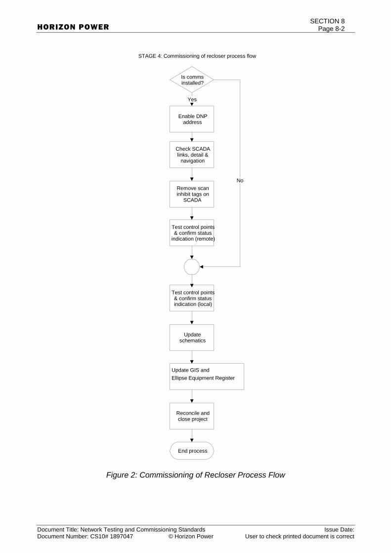
SECTION 8 Page 8-2
Document Title: Network Testing and Commissioning Standards Issue Date: Document Number: CS10# 1897047 © Horizon Power User to check printed document is correct
HORIZON POWER
Figure 2: Commissioning of Recloser Process Flow
Enable DNP address
Remove scan inhibit tags on
SCADA
STAGE 4: Commissioning of recloser process flow
Is comms installed?
Yes
Update schematics
Update GIS and Ellipse Equipment Register
Reconcile and close project
End process
Check SCADA links, detail &
navigation
No
Test control points & confirm status
indication (remote)
Test control points & confirm status indication (local)
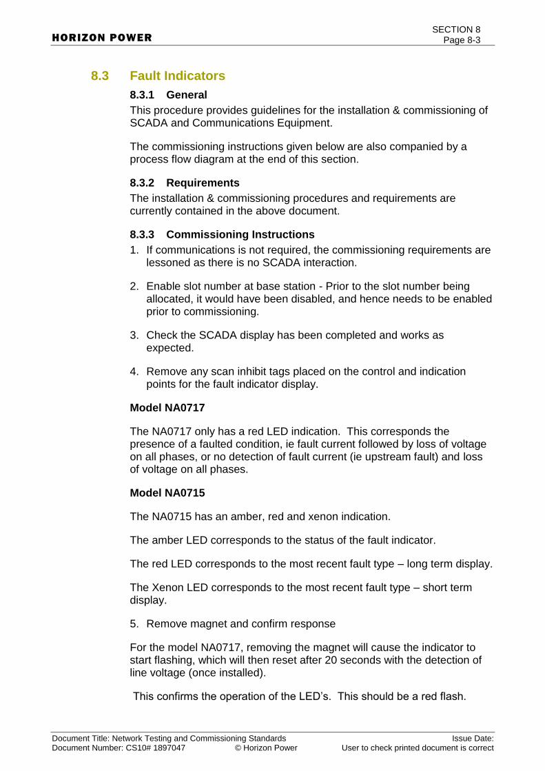
SECTION 8 Page 8-3
Document Title: Network Testing and Commissioning Standards Issue Date: Document Number: CS10# 1897047 © Horizon Power User to check printed document is correct
HORIZON POWER
8.3 Fault Indicators
8.3.1 General
This procedure provides guidelines for the installation & commissioning of SCADA and Communications Equipment.
The commissioning instructions given below are also companied by a process flow diagram at the end of this section.
8.3.2 Requirements
The installation & commissioning procedures and requirements are currently contained in the above document.
8.3.3 Commissioning Instructions
1. If communications is not required, the commissioning requirements are lessoned as there is no SCADA interaction.
2. Enable slot number at base station - Prior to the slot number being allocated, it would have been disabled, and hence needs to be enabled prior to commissioning.
3. Check the SCADA display has been completed and works as expected.
4. Remove any scan inhibit tags placed on the control and indication points for the fault indicator display.
Model NA0717
The NA0717 only has a red LED indication. This corresponds the presence of a faulted condition, ie fault current followed by loss of voltage on all phases, or no detection of fault current (ie upstream fault) and loss of voltage on all phases.
Model NA0715
The NA0715 has an amber, red and xenon indication.
The amber LED corresponds to the status of the fault indicator.
The red LED corresponds to the most recent fault type – long term display.
The Xenon LED corresponds to the most recent fault type – short term display.
5. Remove magnet and confirm response
For the model NA0717, removing the magnet will cause the indicator to start flashing, which will then reset after 20 seconds with the detection of line voltage (once installed).
This confirms the operation of the LED’s. This should be a red flash.
SECTION 8 Page 8-4
Document Title: Network Testing and Commissioning Standards Issue Date: Document Number: CS10# 1897047 © Horizon Power User to check printed document is correct
HORIZON POWER
If this is done prior to installation, the fault indicator can be reset by momentarily placing the magnet on the test point.
For the model NA0715, removing the magnet will cause the fault indicator to test all indication functions which will be a amber, red then xenon (white) flash, one time only.
This confirms the operation of the LED’s and will self-reset.
Unlike earlier CHK fault indicators the lens on the LT30 is permanently attached to the unit. DO NOT ATTEMPT TO REMOVE THE LENS, as this may interfere with the sealing of the enclosure and lead to damage of the internal electronics.
6. Apply magnet test in field (This is only applicable to the NA0717)
a. Apply magnet to test point on base of fault indicator
b. Confirm fault indicator response with Network Control Centre
c. NOTE: Fault Indicator should start flashing after approximately 9 seconds.
d. Remove magnet
e. Wait for fault indicator to reset
f. NOTE: Fault indicator should reset from the energised line after approximately 20 seconds
g. NOTE: If the line is not energised, wait 20 seconds and then momentarily place the magnet at the test point to reset it.
h. Confirm fault indicator response with Network Control Centre
7. Confirm field and SCADA response (As above)
8. Apply SCADA test
a. Test sent from Network Control Centre.
b. NOTE: Fault Indicator should start flashing.
c. Confirm fault indicator response with Network Control Centre.
d. Wait for fault indicator to reset.
e. NOTE: Fault Indicator should reset and stop flashing.
f. Confirm fault indicator response with Network Control Centre.
9. Confirm field and SCADA response
10. Update network schematics by sending a change request to NOCC.

SECTION 8 Page 8-5
Document Title: Network Testing and Commissioning Standards Issue Date: Document Number: CS10# 1897047 © Horizon Power User to check printed document is correct
HORIZON POWER
11. Update GIS and Ellipse Equipment Register with all details required.
12. Reconcile project costs and close project.

SECTION 8 Page 8-6
Document Title: Network Testing and Commissioning Standards Issue Date: Document Number: CS10# 1897047 © Horizon Power User to check printed document is correct
HORIZON POWER
13. Figure 3: Commissioning of Fault Indicator Process Flow
Enable slot number at base
station
Remove scan inhibit tags on
SCADA
Apply magnet test in field & confirm
response
Model NA0717 Model NA0715
Apply SCADA test
Not covered by this process
Yes Yes
No No
Apply SCADA test & confirm response
Remove magnet and confirm response
Remove magnet and confirm response
STAGE 4: Commissioning of fault indicator process flow
Is comms installed?
Yes
Update schematics
Update GIS and Ellipse Equipment Register
Reconcile and close project
End process
Check SCADA links, detail &
navigation
Model NA0717 Model NA0715
Yes Yes
Remove magnet and confirm response
Remove magnet and confirm response
No No
No
SECTION 9 Page 9-7
Document Title: Network Testing and Commissioning Standards Issue Date: Document Number: DMS #1897047 V2 © Horizon Power User to check printed document is correct
HORIZON POWER
9. Testing Requirements
The purpose of this section is to provide instructions for the testing of: -
New cables for commissioning and acceptance of works,
Aged cables after reconstruction work,
Cables after fault repair, and
Switchgear.
The following testing instructions apply: -
9.1 Low Voltage XLPE Cable Testing
9.2 LV Continuity and Phasing Testing
9.3 Low Voltage Cable Testing after repair
9.4 High Voltage XLPE Cable Testing
9.5 High Voltage Paper Insulated Cable Testing
9.6 High Voltage Mixed Cable Testing
9.7 High Voltage Cable Testing after repair of obvious fault
9.8 Earth Testing
9.9 LV Switchgear Testing
9.10 High Voltage Extensible Switchgear Testing
9.11 Substation Design / Installation Check List
9.1 Low Voltage XLPE Cable Testing
9.1.1 Purpose
The purpose of this instruction is to clearly identify the application of the Low Voltage Cable Testing Schedule.
9.1.2 Scope
This instruction is required to be followed for all XLPE insulated LV cable installations in Horizon Power’s distribution network.
All LV cables including cable joints and terminations must be tested following installation, alteration or repair to confirm insulation levels and integrity of the cable system.
9.1.3 References
AS 1178 Concentric Wire Neutral Cables – XLPE Insulated – for electricity supply at working voltages of 0.6/1 kV.
SECTION 9 Page 9-8
Document Title: Network Testing and Commissioning Standards Issue Date: Document Number: DMS #1897047 V2 © Horizon Power User to check printed document is correct
HORIZON POWER
9.1.4 Responsible Persons
The Superintendent or Officer-in-Charge shall be responsible for the performance of testing in accordance with this instruction.
The Tester-in-Charge shall be responsible for carrying out tests in accordance with this instruction and recording all test results and additional comments where relevant.
9.1.5 Test Equipment
The following test equipment is required to carry out the tests nominated in this instruction.
1kV Insulation Resistance Tester (Megger)
9.1.6 Instructions
At the completion of each cable section and prior to the connection of any MEN installations, the insulation resistance of each conductor and the integrity of the sheath shall be tested.
Testing shall be carried out on each identified circuit as follows: –
After all cables are terminated and with all MEN links disconnected/open the following Test XL1 and Test XL2 shall be carried out.
The readings for each test shall be recorded on the Low Voltage XLPE Cable Testing schedule shown over.
9.1.7 Tests
Test XL1 Insulation Resistance Test (IR Test)
Test & Record Insulation Resistance values measured using Megger connected as follows:–
1. Red (R) – White (W)
2. White (W) – Blue (B)
3. Blue (B) – Red (R)
4. Red (R) – Neutral Screen (Nscr)
5. White (W) – Neutral Screen (Nscr)
6. Blue (B) – Neutral Screen (Nscr).
Measured values 10M or greater are acceptable at the point of handover of a clean circuit from the Construction Authority (cable installer) to the Commissioning Authority. Prior to energisation (assuming that sufficient time has lapsed between the handover and the energisation period), the
IR Test must be repeated and measured values not less than 1M (to AS/NZS 3000 Rule 6.3.3.3.2) shall be obtained.
SECTION 9 Page 9-9
Document Title: Network Testing and Commissioning Standards Issue Date: Document Number: DMS #1897047 V2 © Horizon Power User to check printed document is correct
HORIZON POWER
Test XL2 Sheath Integrity Test (SI Test)
With all earth leads/MEN links disconnected test Sheath Integrity using Megger connected Neutral Screen (Nscr) - Earth.
Record the value as measured.
Measured value of 10M or greater is acceptable.
9.1.8 Testing Schedule
Using the Low Voltage XLPE Cable Testing schedule reference, DCT-LV XLPE Cables CS10# 2734392, record the following: –
1. Project Number, Location where Tests carried out and Date of Testing.
2. Record cable identification by describing cable start/finish points.
3. Record cable description, i.e. XLPE, PVC, size (mm2), cores, etc. The Horizon Power ‘Stock Code’ may be used as an acceptable cable description.
4. Record measured insulation resistance (M) of phase to phase and phase to neutral-screen tests.
5. Record measured resistance (M) of sheath integrity from the neutral-screen to earth.
6. The Tester-in-Charge, Consultant/Contractor and Horizon Power Project Inspector to sign off the Testing Schedule.
SECTION 9 Page 9-10
Document Title: Network Testing and Commissioning Standards Issue Date: Document Number: DMS #1897047 V2 © Horizon Power User to check printed document is correct
HORIZON POWER
9.2 LV Continuity and Phasing Testing
9.2.1 Purpose
The purpose of this instruction is to clearly identify the application of the LV Continuity & Phasing Schedule.
9.2.2 Scope
This instruction is required to be followed for all LV insulated cable installations in the Horizon Power distribution network.
9.2.3 References, DCT-LV Cables with or without Pillars CS10# 2734124
9.2.4 Responsible Persons
The Superintendent or Officer-in-Charge shall be responsible for the performance of testing in accordance with this instruction.
The Tester-in-Charge shall be responsible for carrying out tests in accordance with this instruction and recording all test results and additional comments where relevant.
9.2.5 Test Equipment
The following test equipment is required to carry out the tests nominated in this instruction.
500 Volt Megger
Phasing Resistor Box with connection leads.
Ground Resistance Tester.
9.2.6 Instructions
Following completion of installation of a Low Voltage Feeder cable tests are carried out to confirm continuity of conductors, correct phasing of active conductors and positive identification of the neutral conductor.
The start of the Low Voltage Feeder cable shall be connected to a phasing out resistance box only.
Tests shall then be carried out at each and every service pillar, fuse pillar and link pillar on the circuit feeder.
The earth resistance of each earth electrode at each distribution pillar shall be measured and recorded.
9.2.7 Testing Schedule
Using the LV Continuity and Phasing Testing schedule shown, record the following: –
Project Number, Location of Tests, and Date of tests and Tester-in-Charge.
Record location/identification of the termination pillar under test.

SECTION 9 Page 9-11
Document Title: Network Testing and Commissioning Standards Issue Date: Document Number: DMS #1897047 V2 © Horizon Power User to check printed document is correct
HORIZON POWER
Record phase to neutral and neutral to earth values for each test location.
Record the earth resistance at the final MEN test. If the reading is
greater than 1, the record earth resistance of every pillar earth electrode.
The Tester-in-Charge, Consultant/Contractor and Horizon Power Project Inspector to sign off the Testing Schedule.

SECTION 9 Page 9-12
Document Title: Network Testing and Commissioning Standards Issue Date: Document Number: DMS #1897047 V2 © Horizon Power User to check printed document is correct
HORIZON POWER
9.3 Low Voltage Cable Testing after Repair
9.3.1 Purpose
The purpose of this instruction is to outline the minimum testing requirements for Low Voltage Cables prior to re-energising the cable after repair of a fault.
Cables repaired or modified, including all joints and terminations, should be tested to confirm the integrity of the cable after repair.
The described Insulation Resistance test insures that there are no significant further faults on the cable and all shorts, tools and test leads have been removed.
The insulation resistance test is applicable to XLPE; paper insulated or mixed LV cable circuits.
9.3.2 Test Equipment
500 / 1000 V Insulation Resistance Tester (Megger).
9.3.3 Instructions – General
At the completion of the cable repair and prior to reconnecting the consumers, the insulation resistance of each conductor to earth and between conductors shall be tested.
IR Test Insulation Resistance Test
This test confirms the integrity of Insulation Resistance between phase conductors and between phase conductors and neutral screen. Test Insulation Resistance as follows: –
R – W, W – B and B – R. 1000V Insulation Resistance Tester. Record values as measured after 60 seconds of test.
R – N, W – N and B – N. 500V Insulation Resistance Tester. Record values as measured after 60 seconds of test.
Insulation resistance tests must only be conducted when all services on the cable disconnected.
A 500V Insulation Resistance Tester shall be used for tests phase-to-neutral screen.
A 1000V Insulation Resistance Tester shall be used for phase-to-phase testing.
Reference DCT-LV Cables Repair Faults CS10# 2733941

SECTION 9 Page 9-13
Document Title: Network Testing and Commissioning Standards Issue Date: Document Number: DMS #1897047 V2 © Horizon Power User to check printed document is correct
HORIZON POWER
Acceptable Test Result
Typical Test Results 50 M
Acceptable test result 1 M Minimum
If value is below 0.5 M but can sustain the applied
insulation resistance tester voltage (500V) the
circuit can be energised taking extra precaution
when inserting fuses. *
(*The use of a “fuse Mate” device should be
investigated)

SECTION 9 Page 9-14
Document Title: Network Testing and Commissioning Standards Issue Date: Document Number: DMS #1897047 V2 © Horizon Power User to check printed document is correct
HORIZON POWER
9.4 High Voltage XLPE Cable Testing
9.4.1 Purpose
The purpose of this instruction is to clearly outline the testing and commissioning of High Voltage XLPE Cables.
9.4.2 Scope
This instruction must be followed for all High Voltage XLPE cable installations in the Horizon Power Distribution Network.
All High Voltage XLPE cables including cable joints and terminations must be tested following installation, alteration or repair (includes under fault situations) to confirm insulation levels and integrity of the cable system.
9.4.3 References
AS 1429.1 – 2000 Electric Cables – Polymeric insulated – For working voltages 1.9/3.3 (3.6) kV up to and including 19/33 (36) kV.
9.4.4 Responsible Persons
The Project Manager or Officer-in-Charge shall be responsible for the performance of testing in accordance with this instruction.
The Tester-in-Charge shall be responsible for carrying out tests in accordance with this instruction and recording all test results and explanatory comments where relevant.
9.4.5 Test Equipment
The following test equipment is required to carry out the tests nominated in this instruction.
5kV Insulation Resistance Tester (Megger)
VLF Tester 0.1 Hz for test voltage up to 60kV.
9.4.6 Instructions
High voltage D.C. testing SHALL NOT be carried out on XLPE cables. Acceptable test methods are detailed later in this instruction.
XLPE High Voltage cable SHALL NOT be tested using d.c. hi-pot test equipment. High voltage tests may only be conducted using a 5000V Insulation Resistance Meter (Megger) or an approved VLF test set.
Testing shall be carried out: –
After installation and before putting into service.
After repair or cut-in and before putting back into service.
All XLPE high voltage cables shall be tested in accordance with the following: –
Transformer cables (≤250 metres and without in-line joint) – Test X1 and Test X3.

SECTION 9 Page 9-15
Document Title: Network Testing and Commissioning Standards Issue Date: Document Number: DMS #1897047 V2 © Horizon Power User to check printed document is correct
HORIZON POWER
Transformer cables (>250 metres and/or with in-line joint) – Test X1, Test X2 and Test X3.
Feeder cables – Test X1, Test X2 and Test X3.
9.4.7 Tests
Test X1 Insulation Resistance Test (IR Test)
Test Insulation Resistance using 5kV Megger between conductor and
screen. Record measured values. Values greater than 10,000 M are acceptable.
Refer to: Testing of High Voltage Cables Manual DM # 36513089 – Published by Horizon Power
Test X2 Very Low Frequency Test (VLF Test)
Using VLF tester, test between conductors to screens (which shall be earthed) for 60 minutes at a voltage of 3VN @ 0.1 Hz. Acceptable when no breakdown occurs.
System Voltage
VN Test Voltage 3VN
6.6 kV 3.8 kV 11.5 kV
11 kV 6.35 kV 19.0 kV
22 kV 12.7 kV 38.0 kV
33 kV 19.1 kV 57.0 kV
Note: Repetitive or successive VLF testing of a cable should be avoided
Test X3 Sheath Integrity Test (SI Test)
Test sheath integrity using 1kV Megger between screen and Earth. Record measured values on Distribution Commissioning Test Sheet
CS10#2734034. Values greater than 1,000 M are acceptable.
9.4.8 Testing Schedule
Using the High Voltage XLPE Testing schedule reference DCT-HV XLPE Cables CS10# 2734034, record the following: –
Project Number, Location where Tests carried out and Date of Testing.
Record cable start/finish points.
Record cable description, ie. XLPE, paper insulated screened, size mm2, cores, etc. The Horizon Power ‘Stock Code’ is an acceptable

SECTION 9 Page 9-16
Document Title: Network Testing and Commissioning Standards Issue Date: Document Number: DMS #1897047 V2 © Horizon Power User to check printed document is correct
HORIZON POWER
cable description. Record cable function, i.e. transformer cable or feeder cable.
Record measured insulation resistance (M) of each phase conductor to screen.
Record measured resistance (M) of sheath integrity from the screen of each core to Earth.
Record the test voltage and duration of VLF testing. Record test result as Pass when no breakdown of conductor insulation occurs during the test.
The Tester-in-Charge, Consultant/Contractor and Horizon Power Project Inspector to sign off the Testing Schedule.
9.5 High Voltage Paper Insulated Cable Testing
9.5.1 Purpose
The purpose of this instruction is to clearly outline the testing and commissioning of Paper Insulated High Voltage Cables.
9.5.2 Scope
This instruction must be followed for all HV paper insulated cable installations in the Horizon Power Distribution Network.
All HV paper insulated cables including cable joints and terminations must be tested following installation, alteration or repair to confirm insulation levels and integrity of the cable system.
9.5.3 References, DCT-HV PILC Screened Cables CS10# 2733834
AS 1026 Electric Cables, impregnated paper insulated, working voltages up to and including 33kV.
9.5.4 Responsible Persons
The Project Manager or Officer-in-Charge shall be responsible for the performance of testing in accordance with this instruction.
The Tester-in-Charge shall be responsible for carrying out tests in accordance with this instruction and recording all test results and explanatory comments where relevant.
9.5.5 Test Equipment
The following test equipment is required to carry out the tests nominated in this instruction.
5kV Insulation Resistance Tester (Megger)
Single output (D.C. negative) Hi-pot tester for test voltage up to 60 kV.
Positive /negative output D.C. Hi-pot tester for test voltages up to 27 kV.

SECTION 9 Page 9-17
Document Title: Network Testing and Commissioning Standards Issue Date: Document Number: DMS #1897047 V2 © Horizon Power User to check printed document is correct
HORIZON POWER
9.5.6 Instructions
Paper insulated cables may be of belted or screened construction.
There are many belted 6.6kV and 11kV cables in service and will remain for a long time.
All paper insulated cables connected to system voltages greater than 11kV are of screened construction (belted cables are not manufactured for system voltages greater than 11kV).
Paper Insulated Belted Cables
Faults on these cables may occur between cores or between core and sheath.
Testing shall be carried out after repair or cut-in and before putting back into service.
High voltage paper insulated belted cables shall be subjected to Test B1 and Test B2 as follows:–
Test B1 Insulation Resistance Test (IR Test)
Insulation Resistance is tested using a 5kV Megger connected conductor to conductor and between conductors to sheath. Record measured values.
Test B2 Hi-Pot Test
A single output (negative) tester or a positive and negative output tester may be used for all conductors to sheath hi-pot test.
The conductors shall be connected to the negative output.
A cable tester with positive and negative outputs must be used for conductor to conductor hi-pot testing.
A cable tester with single terminal (negative) high voltage output SHALL NOT be used for core to core testing.
In accordance with the cable designated voltage or system voltage, apply the recommended
Test D.C. Voltage for 15 minutes between all conductors connected together and sheath (R+W+B to Sheath). Cable sheath is earthed.
Test is acceptable when no breakdown occurs.
In accordance with cable designated voltage or system voltage, apply the Test D.C. Voltage for 15 minutes R to W+B and W to B+R. Cable sheath is earthed. Test is acceptable when no breakdown occurs.
Cable designation
Test d.c. Voltage(1) applied for 15 minutes.

SECTION 9 Page 9-18
Document Title: Network Testing and Commissioning Standards Issue Date: Document Number: DMS #1897047 V2 © Horizon Power User to check printed document is correct
HORIZON POWER
Or system voltage
KV
Between all conductors to sheath belted
cables
kV
Between conductor to
conductor belted cables
kV
3.8/6.6 12.0 16.0
6.35/11 20.0 27.0
Test voltage (belted cables) after repair or cut-in
Note (1) Test D.C. voltage is based on AS 1026 Table B3 with an applied de-rating factor of 0.8. This factor accommodates the service ageing of cables.
Paper Insulated Screened Core Cables
Faults mainly occur in these cables from core to earth because each core is continuously wrapped in metal foil (the screen).
The only exception to this is at the cable terminations, where the foil is cut back. This creates the small risk of a core to core fault at this location.
Testing shall be carried out: –
After installation and before putting into service.
After repair or cut-in and before putting back into service.
High voltage paper insulated screened cables shall be subjected to Test S1 and Test S2 as follows: –
Test S1 Insulation Resistance Test (IR Test)
Insulation Resistance is tested using a 5kV Megger connected conductor to screen, and record measured values.
Test S2 Hi-Pot Test
A single output (negative) tester shall be used for all conductors to screen hi-pot test.
Conductors shall be connected to the negative output.
In accordance with the cable designated voltage or system voltage whichever is the lesser, apply the recommended Test D.C. Voltage for 15 minutes R+W+B to earth.
Conductor screen(s) and metallic cable sheath are earthed.
Test is acceptable when no breakdown occurs.

SECTION 9 Page 9-19
Document Title: Network Testing and Commissioning Standards Issue Date: Document Number: DMS #1897047 V2 © Horizon Power User to check printed document is correct
HORIZON POWER
Cable designation
Or system voltage
KV
Test d.c. Voltage applied for 15 minutes between conductor(s) and
earth.
New cables
kV
Service aged cables.
KV(2)
6.35/11 25.0 20.0
12.7/22 50.0 40.0
19/33 75.0 60.0
Test voltages (screened cables)
Note (2): Test voltages are based upon AS 1026 Table B3 and with a de-rating factor of 0.8 for Service Aged cables greater than 3 years.
9.5.7 Testing Schedule
Using the applicable Testing Schedule shown, record the following: –
1. Project Number, Location where Tests carried out, and Date of testing and Tester-in-Charge.
2. Record cable start/finish points.
3. Record cable description, i.e. Paper insulated screened, size mm2, cores, etc.
4. The Horizon Power ‘Stock Code’ is an acceptable cable description.
5. Record cable function, i.e. transformer cable or feeder cable.
6. Record measured insulation resistance (M) of conductors to earth and conductor to conductor as appropriate.
7. Record results of Hi-Pot test(s).
8. The Tester-in-Charge, Consultant/Contractor and Horizon Power Project Inspector to sign off the Testing Schedule.
END OF INSTRUCTION
SECTION 9 Page 9-20
Document Title: Network Testing and Commissioning Standards Issue Date: Document Number: DMS #3127547 V2 © Horizon Power User to check printed document is correct
HORIZON POWER

SECTION 9 Page 9-21
Document Title: Network Testing and Commissioning Standards Issue Date: Document Number: DMS #1897047 V2 © Horizon Power User to check printed document is correct
HORIZON POWER
9.6 High Voltage Mixed Cable Testing
9.6.1 Purpose
The purpose of this instruction is to clearly outline the testing and commissioning procedure for High Voltage Cables with differing insulation materials and/or construction, which are inseparably linked.
9.6.2 Scope
This instruction must be followed for all High Voltage Mixed Cable installations in the Horizon Power Distribution Network.
All HV cables including cable joints and terminations must be tested following installation, alteration or repair to confirm insulation levels and integrity of the cable system.
9.6.3 References
AS 1026 Electric Cables – Impregnated Paper Insulated – Working voltages up to and including 33kV.
AS 1429.1 Electric Cables – Polymeric insulated – For working voltages 1.9/3.3 (3.6) kV up to and including 19/33 (36) kV.
9.6.4 Responsible Persons
The Project Manager or Officer-in-Charge shall be responsible for the performance of testing in accordance with this instruction.
The Tester-in-Charge shall be responsible for carrying out tests in accordance with this instruction and recording all test results and explanatory comments where relevant.
9.6.5 Test Equipment
The following test equipment is required to carry out the tests nominated in this instruction.
5kV Insulation Resistance Tester
9.6.6 Instructions
High voltage D.C. testing SHALL NOT be carried out on XLPE cables.
Paper insulated cables may be of belted or screened construction.
There are many belted 6.6kV and 11kV cables in service and will remain for a long time.
All paper insulated cables connected to system voltages greater than 11kV are of screened construction (belted cables are not manufactured for system voltages greater than 11kV).
Whenever possible the testing of individual cables comprising a mixed cable circuit should be completed before the cables are inseparably linked.
XLPE and Paper Insulated Cables Inseparably Linked.

SECTION 9 Page 9-22
Document Title: Network Testing and Commissioning Standards Issue Date: Document Number: DMS #1897047 V2 © Horizon Power User to check printed document is correct
HORIZON POWER
High Voltage circuits comprising mixed cables shall be tested: –
After installation, termination and linking of mixed cables,
After repair or alteration to a circuit of mixed cables.
The linking together of different types of cables in a circuit imposes limitations on permissible commissioning tests.
9.6.7 Tests
Circuits comprising two or more cables of differing insulation material and/or construction which are inseparably linked shall be subjected to Test M1 and Test M2 as follows: –
Test M1 Insulation Resistance Test (IR Test)
Insulation Resistance is tested using a 5kV Insulation Resistance Tester connected, conductor to conductor and between conductors and earth. Record measured values.
Test M2 Soak Test
Energise the cable at system voltage and frequency and monitor for 24 hours, the test is acceptable when no breakdown occurs within the monitored period.
Note. This test should be done at no load; however this may not always be practicable.
9.6.8 Testing Schedule
Using the High Voltage Mixed Cable Testing Schedule, Reference DCT-Mixed Cables CS10# 2734491
Project Number, Location where Tests carried out, and Date of testing and Tester-in-Charge.
1. Record cable start/finish points.
2. Record cable descriptions, i.e. XLPE, paper insulated screened, size mm2, cores, etc. The Horizon Power ‘Stock Code’ is an acceptable cable description.
3. Record cable function, i.e. transformer cable or feeder cable.
4. Record measured insulation resistance (M) of each phase conductor to earth.
5. Record Soak Test result after application of system voltage for 24 hours.
6. The Tester-in-Charge, Consultant/Contractor and Horizon Power Project Inspector to sign off the Testing Schedule.
SECTION 9 Page 9-23
Document Title: Network Testing and Commissioning Standards Issue Date: Document Number: DMS #1897047 V2 © Horizon Power User to check printed document is correct
HORIZON POWER
9.7 High Voltage Cable Testing after Repair of Obvious Fault
9.7.1 Purpose
The purpose of this instruction is to outline the minimum testing requirements for High Voltage Cables after repair of an obvious fault such as a failed cable termination, joint or external damage.
Additional HV testing that is not covered in this work instruction has to be carried out if: -
1. The cable itself failed without obvious cause such as an internal fault.
2. Repair involves a transition joint.
3. The cable has a history of repeated faults.
4. The cable cannot be remotely energised or is not protected by HV fuses.
5. The cable is of strategically high importance such as a main feeder for the CBD area or hospital.
6. Major alteration or major repair work undertaken (e.g. Replacement of significant cable length).
7. The cable does not meet the minimum insulation resistance as per Table 1 (below).
The above tests insure that there are no significant faults remaining on the cable and all shorts, tools and test leads have been removed.
The insulation resistance test is applicable to XLPE; paper insulated or mixed HV cable circuits.
9.7.2 Definitions
XLPE
Cross Linked Polyethylene
PILC
Paper Insulated Lead Covered Cable
Earth
An effective electrical connection to the general mass of Earth which may be achieved by way of connection to an existing earth system on the site (where available), by connection to a buried metallic water pipe or by connection to a driven copper stake not less than 12 mm diameter x 500 mm long.
9.7.3 Test Equipment
5kV Insulation Resistance Tester
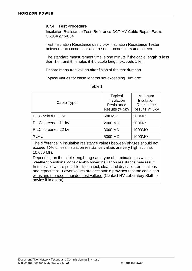
SECTION 9 Page 9-24
Document Title: Network Testing and Commissioning Standards Issue Date: Document Number: DMS #1897047 V2 © Horizon Power User to check printed document is correct
HORIZON POWER
9.7.4 Test Procedure
Insulation Resistance Test, Reference DCT-HV Cable Repair Faults CS10# 2734034
Test Insulation Resistance using 5kV Insulation Resistance Tester between each conductor and the other conductors and screen.
The standard measurement time is one minute if the cable length is less than 1km and 5 minutes if the cable length exceeds 1 km.
Record measured values after finish of the test duration.
Typical values for cable lengths not exceeding 1km are:
Table 1
Cable Type
Typical Insulation
Resistance Results @ 5kV
Minimum Insulation
Resistance Results @ 5kV
PILC belted 6.6 kV 500 M 200M
PILC screened 11 kV 2000 M 500M
PILC screened 22 kV 3000 M 1000M
XLPE 5000 M 1000M
The difference in insulation resistance values between phases should not exceed 30% unless insulation resistance values are very high such as
10,000 M.
Depending on the cable length, age and type of termination as well as weather conditions, considerably lower insulation resistance may result. In this case where possible disconnect, clean and dry cable terminations and repeat test. Lower values are acceptable provided that the cable can withstand the recommended test voltage (Contact HV Laboratory Staff for advice if in doubt).

SECTION 9 Page 9-25
Document Title: Network Testing and Commissioning Standards Issue Date: Document Number: DMS #1897047 V2 © Horizon Power User to check printed document is correct
HORIZON POWER
9.8 Earth Testing
9.8.1 Purpose
The purpose of this instruction is to clearly identify the application of the Earth Testing Schedule.
9.8.2 Scope
This instruction is required to be followed for all earth resistance testing in the Horizon Power distribution network.
9.8.3 References
AS/NZS 3000 – 2000 Electrical Installations (known as Wiring Rules)
9.8.4 Responsible Persons
The Superintendent or Officer-in-Charge shall be responsible for the performance of testing in accordance with this instruction.
The Tester-in-Charge shall be responsible for carrying out tests in accordance with this instruction and recording all test results and additional comments where relevant.
9.8.5 Test Equipment
The following test equipment is required to carry out the tests nominated in this instruction.
Ground Resistance Tester
9.8.6 Instructions
For combined earthing systems measure resistance to earth of the completed system with all earth connections and neutral-earth connections in place, and record the results.
For separate earthing systems, measure the resistance to earth of the high voltage earthing system and the low voltage system independently and separately.
The measurements shall be made independently of any connection between the neutral conductor and earth elsewhere within the electrical installation, and record the results.
Evaluate results obtained with requirements of AS/NZS 3000 Section 7.8.10. Refer the following extracts –
Resistance to earth – Combined Earth system
The combined earth system shall have a resistance to earth not greater
than 1 .
The resistance of 1 may be achieved by connections to electrode systems, metallic cable sheaths or low voltage neutrals, provided that when any such connection is temporarily removed for test or maintenance
SECTION 9 Page 9-26
Document Title: Network Testing and Commissioning Standards Issue Date: Document Number: DMS #1897047 V2 © Horizon Power User to check printed document is correct
HORIZON POWER
purposes the resistance of the remaining earth connections does not
exceed 30 .
Resistance to earth greater than 1, may be appropriate where step and touch potentials are satisfactory.
Resistance to earth – Separate Earthing system
The earth connections of the earthing systems shall be located, installed and maintained so that the resistance to earth shall not exceed the following:
(a) High Voltage system 30
(b) Low voltage system:
(i) Aggregate transformer rating up to 50 kVA
30
(ii) Aggregate transformer rating over 50 kVA but not more than 500 kVA
15
(iii) Aggregate transformer rating over 500 kVA
10
The resistance specified in Items (a) and (b) shall be achieved independently of any connections between the neutral conductor and earth at other points within the electrical installation.
9.8.7 Testing Schedule
Using the Earth Testing schedule record the following, Reference DCT-Earth Resistance Testing CS10# 2733633.
1. Project Number, Location of Tests, and Date of tests and Tester-in-Charge.
2. Record location/identification of the earth connection/system under test.
3. Record earth resistance values for each test location.
4. The Tester-in-Charge, Consultant/Contractor and Horizon Power Project Inspector to sign off the Testing Schedule and include appropriate registration/licensing number where applicable.

SECTION 9 Page 9-27
Document Title: Network Testing and Commissioning Standards Issue Date: Document Number: DMS #1897047 V2 © Horizon Power User to check printed document is correct
HORIZON POWER
9.9 LV Switchgear Inspection and Testing
9.9.1 Purpose
The purpose of this instruction is to detail the general requirements of inspection and testing Low Voltage switchgear.
9.9.2 Scope
This instruction is required to be followed for all Low Voltage Switchgear inspection and testing in the Horizon Power distribution network.
9.9.3 References
AS/NZS 3000 – 2000 Electrical Installations (known as Wiring Rules)
9.9.4 Responsible Persons
The Superintendent or Officer-in-Charge shall be responsible for the performance of inspection and testing generally in accordance with this instruction.
The Tester-in-Charge shall be responsible for carrying out all necessary inspections and tests to verify the Low Voltage Switchgear is suitable for operational service. Any defects or anomalies found, as a result of inspection and testing shall be recorded.
9.9.5 Test Equipment
The following test equipment is required to carry out the tests nominated in this instruction.
1000 volt Insulation Resistance Tester
Continuity Tester
9.9.6 Instructions
The following sets out some guidelines for the Inspection and Testing of LV Switchgear. The points listed below are not deemed to be an exhaustive list of checks applicable to the variety of LV Switchgear used in the distribution network. Additional checks may be necessary according to the equipment, the arrangement and the environment of use.
1. Check the enclosure is satisfactory for the environment at the location of installation.
2. Check the electrical equipment complies with relevant design drawings.
3. Check the voltage rating of electrical equipment is suitable for the nominal supply voltage.
4. Check each item of electrical equipment is suitable for the design current loadings and/or over current protection devices.
5. Check for protection against indirect contact by way of arrangement, barriers or screens.
6. Check minimum clearances and creepage distances are maintained.
SECTION 9 Page 9-28
Document Title: Network Testing and Commissioning Standards Issue Date: Document Number: DMS #1897047 V2 © Horizon Power User to check printed document is correct
HORIZON POWER
7. Check mechanical operation of all switches, fuse holders and fuse ways.
8. Check all electrical equipment is labelled and identified in accordance with relevant drawings.
9.9.7 Tests
1. Check Insulation Resistance between active conductors and between
neutral and active conductors to earth is 10 M or greater using 1000-volt tester.
2. Check circuit continuity as necessary.
SECTION 9 Page 9-29
Document Title: Network Testing and Commissioning Standards Issue Date: Document Number: DMS #1897047 V2 © Horizon Power User to check printed document is correct
HORIZON POWER
9.10 High Voltage Extensible Switchgear Testing
9.10.1 Purpose
The purpose of this instruction is to clearly identify the application of the HV Switchgear testing Schedule.
9.10.2 Scope
This instruction is required to be followed for all HV switchgear which is to be connected to the Horizon Power distribution network.
9.10.3 References
• AS 2067 Switchgear assemblies and ancillary equipment for alternating voltages above 1kV.
• AS 2650 Common specifications for high-voltage switchgear and control gear standards.
9.10.4 Responsible Persons
The Superintendent or Officer-in-Charge shall be responsible for the performance of testing in accordance with this instruction.
The Tester-in-Charge shall be responsible for carrying out tests in accordance with this instruction and recording all test results and explanatory comments where relevant.
9.10.5 Test Equipment
The following test equipment is required to carry out the tests nominated in this instruction.
5000 volt Megger
9.10.6 Instructions
With all switches closed and external high voltage cables disconnected, Megger phase to phase and phase to earth.
This schedule is used where modular or extensible switchgear has been assembled on-site, and is used in addition to the HV Switchgear Testing Schedule.
Extensible high voltage switchgear assembled in a workshop and transported to site or assembled on site shall be tested on site to prove correct assembly and maintained level of insulation for the rated voltage.
The following testing shall be carried out prior to the switchgear assembly being energised, Reference DCT-HV RMU Switchgear CS10# 2733547.
SECTION 9 Page 9-30
Document Title: Network Testing and Commissioning Standards Issue Date: Document Number: DMS #1897047 V2 © Horizon Power User to check printed document is correct
HORIZON POWER
9.10.7 Tests
Test 1 Visual Inspection
Visual and hand inspection of all accessible electrical connections made during assembly.
Inspect all insulators for damage and cleanliness, clean where necessary.
Test 2 Operational Test.
Operate all switch mechanisms for proper functioning.
Test continuity on all phases for closed switches and open circuit for switches in the off position.
Test all auxiliary devices such as auxiliary switches, protection transformers and fault indicators.
Test earth switches.
Test all interlock mechanisms to confirm correct functioning and test interlock mechanisms inhibit function for improper operational actions.
Note:
Interlocks that have only been tested to confirm that an operational action is allowed when such an action is permissible, has not been fully tested.
Interlock mechanisms must be tested to confirm that an operational action is positively prevented when that action should never occur.
Test 3 Insulation Resistance Test
Megger all phases to earth and phase to phase and record the results.
9.10.8 Testing Schedule
Using the High Voltage Extensible Switchgear Testing schedule shown, record the following:
1. Project Number, Location where Tests carried out, and Date of testing and Tester-in-Charge.
2. Record a brief description of the switchgear.
3. Record comments on Visual checks, Operational and Interlock checks carried out.
4. Record measured insulation resistance (M) of each phase to phase and phase to earth test.
5. Record results of High Voltage Withstand Test carried out.
6. The Tester-in-Charge, Consultant/Contractor and Horizon Power
SECTION 9 Page 9-31
Document Title: Network Testing and Commissioning Standards Issue Date: Document Number: DMS #1897047 V2 © Horizon Power User to check printed document is correct
HORIZON POWER
Project Inspector to sign off the Testing Schedule.

SECTION 1 Page 9-32
Document Title: Network Testing and Commissioning Standards Issue Date: Document Number: DMS #1897047 V2 © Horizon Power User to check printed document is correct
HORIZON POWER
9.11 Substation Design/Installation Check List
1. COMMON CONDITIONS
PASS FAIL
Fire Protection
1. Fire risk zone/ need for an enclosure determined
2. If substation not 2 hr fire rated, no buildings, structures or essential fire escapes/exits in fire risk zone or other
buildings 2 hour fire rated
Access
3. Access suitable for heavy vehicles, max slope 1: 10
4. Area immediately around substation level
5. Access suitable for transformer installation (1.5 m high,
1.9 m wide, 1.6 m long, 5 tonne mass)
6. Access for Horizon Power staff 24 hours/day, 7 days/week
7. If the gatic cover is installed:
8. clear opening dimensions of 2.5 m x 2.0 m
9. minimum clear ceiling height above the gatic cover of 3.3 m
10. monorail or lifting eyes installed
11. access from street or ROW, no obstructions
Consumer's Mains & Main Switches
12. Correct consumer's mains provided
13. Main switchboard contiguous if required by load
14. Mechanical interlocking provided where necessary
15. Switchboard layout/design submitted
16. Adequate main switch provided
17. Protection setting information provided
18. Protection test results provided
19. For Customer Owned substations, same HV switch gear used
as Horizon Power or joggle chamber type test certificates submitted

SECTION 2 Page 2-33
Document Title: Network Testing and Commissioning Standards Issue Date: Document Number: DMS #1897047 V2 © Horizon Power User to check printed document is correct
HORIZON POWER
2. ADDITIONAL CONDITIONS WHERE SUBSTATION ENCLOSURE NOT REQUIRED
Site Requirements & Preparation
1. No obstacles or non removable surface treatments within site
2. Site located above 100 year flood level and suitably retained/drained.
No other services within site
3. Site level, compacted sand to 1 m depth, compaction certificate supplied
4. Concrete barrier curb installed around site if traffic risk exists
5. Site stabilised to prevent soil erosion
Screening
6. Proposed screening discussed and agreed with Horizon Power
and not installed until Horizon Power finished on site
7. Where full screening proposed, two openings provided
(& suitable doors supplied if required)
8. Where screening to be roofed, Horizon Power consulted regarding
ventilation & equipment access
9. No part of screening within site nor more than 550mm below FGL
10. Metallic screening suitably earthed
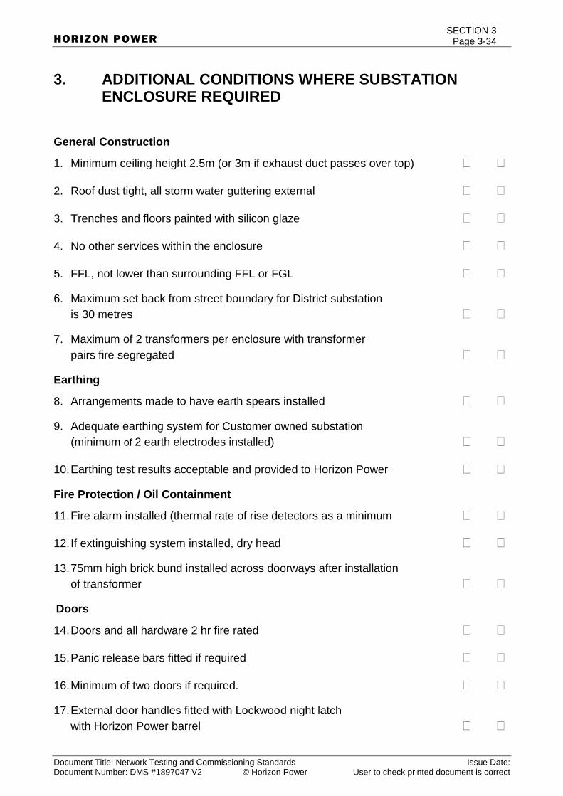
SECTION 3 Page 3-34
Document Title: Network Testing and Commissioning Standards Issue Date: Document Number: DMS #1897047 V2 © Horizon Power User to check printed document is correct
HORIZON POWER
3. ADDITIONAL CONDITIONS WHERE SUBSTATION ENCLOSURE REQUIRED
General Construction
1. Minimum ceiling height 2.5m (or 3m if exhaust duct passes over top)
2. Roof dust tight, all storm water guttering external
3. Trenches and floors painted with silicon glaze
4. No other services within the enclosure
5. FFL, not lower than surrounding FFL or FGL
6. Maximum set back from street boundary for District substation
is 30 metres
7. Maximum of 2 transformers per enclosure with transformer
pairs fire segregated
Earthing
8. Arrangements made to have earth spears installed
9. Adequate earthing system for Customer owned substation
(minimum of 2 earth electrodes installed)
10. Earthing test results acceptable and provided to Horizon Power
Fire Protection / Oil Containment
11. Fire alarm installed (thermal rate of rise detectors as a minimum
12. If extinguishing system installed, dry head
13. 75mm high brick bund installed across doorways after installation
of transformer
Doors
14. Doors and all hardware 2 hr fire rated
15. Panic release bars fitted if required
16. Minimum of two doors if required.
17. External door handles fitted with Lockwood night latch
with Horizon Power barrel

SECTION 3 Page 3-35
Document Title: Network Testing and Commissioning Standards Issue Date: Document Number: DMS #1897047 V2 © Horizon Power User to check printed document is correct
HORIZON POWER
18. Appropriate labels and Danger Signs fitted to all doors
19. Doors do not open directly onto trafficable areas
Ventilation
20. Fire dampened vents fitted (rotating blades, thermal links)
21. Pressure relief vents installed in accordance with drawings
22. All vents fitted with external louvres
23. Forced draught ventilation installed if required
Trenches Ducts and Other Penetrations
24. All trenches installed in accordance with drawings
25. All trench covers provided (20mm thick ply in lengths not
exceeding 1 meter)
26. Cable pulling eye installed in trench if enclosure more than 20
meters from street boundary
27. All ducts installed in accordance with drawings, with minimum
cover of 850mm.
28. All ducts and penetration entering enclosure fitted with
removable water tight seals prior to handover
Lighting and GPO
29. All necessary lighting, GPOs and minor wiring installed in Sole
Use and Customer owned substations
Metering For HV Installations
30. In HV installations, metering panel installed on the external south facing wall, with a 75mm diameter PVC conduit installed from trench
to metering panel.
Customer Switching
31. For HV installation, switching operator nominated
END OF INSTRUCTION

SECTION 3 Page 3-36
Document Title: Network Testing and Commissioning Standards Issue Date: Document Number: DMS #1897047 V2 © Horizon Power User to check printed document is correct
HORIZON POWER
References to Distribution Commissioning Test Sheets


