

NEW VISION CONCEPT SCHOOL PORTAL
By
SINDHU THOTAKURA
Bachelor of Engineering, Jawaharlal Nehru Technological University, India, 2010
M.S., Kansas State University, 2012
A REPORT
Submitted in the partial fulfillment of the requirements for the degree
MASTER OF SOFTWARE ENGINEERING
Department of Computing and Information Sciences
College of Engineering
Kansas State University
Manhattan, Kansas
2012
Approved By:
[Major Professor]
Dr. Mitchell Neilsen

ABSTRACT
The objective of New Vision Concept School Portal is to design a website for New
Vision Concept School Located in India and get familiar to .NET framework. The portal
has been designed using C#.NET technology and to store the information SQL server
2008 is used as the database for the project. My motivation for the project came from my
enthusiasm and strong urge to learn C# and.NET which is one of the fastest growing
technologies in today’s world. The New Vision Concept School Portal is mainly designed
for the users who would like to know the information about school, admissions etc. It is
also designed for the students and teacher. Teachers can login to the website and update
the student Homework information and Results. Students can login to the website and
view their respective homework and results. All the data needed for the application is
stored in the form of tables in the SQL server 2008. The report contains the details of all
the tasks carried out during the entire software development life cycle of the New Vision
Concept School Portal. This document depicts all the details of the project starting from
the project design to testing.
Table of Contents
Chapter 1 - Vision Document ........................................................................................1
Chapter 2 - Project Plan ...............................................................................................15
Chapter 3 - Architecture Design ..................................................................................24
Chapter 4 - Software Quality Assurance Plan .............................................................41
Chapter 5 - Inspection Checklist ..................................................................................47
Chapter 6 - Test Plan....................................................................................................49
Chapter 7 - Assessment Evaluation .............................................................................55
Chapter 8 - User Manual ..............................................................................................66
Chapter 9 - Project Evaluation .....................................................................................76
References ....................................................................................................................81

1
Chapter 1 - Vision Document
1. Introduction
The main goal of the project is to develop a web application for New Vision Concept
School which is located in India.
1.1. Purpose and Motivation
The main purpose of this vision document is to list all the requirements of the NVCS
portal. At present there is no website for New Vision Concept School and if the users
want to know anything about the school or the students want to know the list of events or
any other information, the only way is to go to the school or make a phone call to the
school. Therefore it would be better to develop a portal by which students can view any
required information and also the visitors can browse the information through the portal.
I prefer doing this portal in C#.NET as it is a technology which is being used a lot in IT
field. My interest to learn this technology has prompted to take this project, which would
set the stage for the applications I would be developing in the future.
1.2. Project Overview
The New Vision Concept School Portal is designed mainly for three types of users:
visitors, students and teachers of New Vision Concept School. This helps the users
browse through the different events of school, students can get the information online
which includes balance due, class schedule, marks secured, assignments to be done etc.
This portal has the following pages and features.
Home
The most important information should be included in this page as the user will be
directed to this page by search engines when user tries to know about the school.
Therefore news, Events, Contact information, slide show of images is included here.
Login

5
There are two types of the users for system Student and Teacher. The user should register
in the administrative office who give id and password to the user by which he can login.
The online registration is not provided for security purposes.
Students would be able to view their marks online. They can also view their
marks in the graphical format.
Teacher can update the marks of a student and can also view the reports of the
classes taught by teacher in a graphical format.
The reports can be viewed in graphical format by the users so that it would be
easy to assess.
About us
This page includes all the information about school by which user can know better about
the school. The information include
Campus area, Libraries, Laboratories, Number of campuses and their description.
Facilities provided by school which includes Transportation , Dining Facility,
Accommodation, Tours and Activities, Safety and Security, Life Style, Medical
Facilities, Water Purifier.
Number of staff working for the school in each department.
Cultural and other activities by school.
Admissions
This page includes the admission procedure, Criteria for admissions, Application
procedure, details regarding the Aptitude/Entrance test, documents required for the
student to apply, Required age for the admission. Also, student will be able to take the
practice exams.
Academics
This page includes the course curriculum of various standards and also different
methodologies of teaching. Along with that the fee structure, information about the
teaching staff and the principal’s message can be viewed.

6
School Campus
All the information about the campus can be viewed here like Transportation, Dining
Facility, Accommodation, Tours, Safety, Life style, Medical facilities, Water Purifier
with the images representing them.
Beyond Academics
This User can browse the information of the activities that school offers apart from the
academics. They include Learning Resource Center, Classroom Resource Center, Life
Skills, Mathematics Exploratory, Music and Drama, Drawing/Art Studio,
Yoga/Meditation.
Campus Activities
The User can view the ongoing events information like cultural activities, news board,
Admissions.
Contact us
This User can get the contact information including email id and phone numbers of
important persons of the school, address of the school, Google Map showing the address
of school and the contact form where user can fill the form and submit in case of any
questions. Apart from this User can provide the feedback about the school.
Online Chat
The visitor of the website can chat with the administrator in the times specified by the
administrator. The administrator will specify the timings which he is available by posting
them on the website. The Visitor can chat online regarding their queries in the specified
times.
1.3.References
1. IEEE Recommended Practice for Software Requirements Specification.
2. Portfolio Requirements Page from CIS Webpage, Kansas State University.
7
3. Writing Hints by Dr. DeLoach
(http://people.cis.ksu.edu/~sdeloach/index.php?option=com_content&view=articl
e&id=58&Itemid=92)
4. Wikipedia
5. Vision Document 1.0
2. Product Description
2.1. Product Perspective
The New Vision Concept School Portal uses the .NET framework and is completely
independent. The project need not be introduced into a larger system as it is a bigger
project. This project can run on any operating system.
2.2. Product Features
This project is mainly intended for two types of audience: Students and Teachers. The
Use case diagrams are shown below.
Student Use Case diagram:

8

9
Teacher Use Case diagram
2.3.Assumptions and Dependencies
To view the content of the Webpage, the user needs to have an active internet connection.
As of now, this is the only assumption.
2.4. Environment
The .NET technology is used to code the project and SQL Server 2008 which is
integrated in the Microsoft Visual Studio 2010 is used as a database. Apart from that
HTML, CSS, JQuery will also be used.
2.5.Constraints
10
As the information stored in the database increases, the server might be overloaded and
information to retrieve may be delayed as the database is designed to be a moderate size.
The SQL Server 2008 acts as the database for the project.
3. Requirements Specification
3.1.Use Case name: User Login/Logout
Purpose: The User can login into the system to view the particular information.
Actor: Student, Teacher
Input: The User should provide the User Name and Password to login. If the user forgets
the password user can also request for the new password.
Output: The system checks the user authentication by verifying the User Name and
Password given by the user matches with the details in the database. If it matches the user
can successfully login to the system and access the required information.
3.2.Use Case name: View Individual results
Purpose: The User can view the individual results in each subject along with the total
marks, rank and teacher comments.
Actor: Student
Input: The user just clicks on the icon showing the individual results.
Output: The individual results which are stored in database will be retrieved and
displayed to the user.
3.3.Use Case name: View Class results
Purpose: The user can view the results of the class in graphical format. This helps user to
assess about him properly.
Actor: Student
Input: The user just clicks on the icon showing class results.
Output: The class results which are stored in database are retrieved from the database and
are displayed in a graphical format.
3.4.Use Case name: View Balance Due
11
Purpose: The user can view the balance due of the tuition fee. This helps the student to
know the last date of payment and can pay the fee promptly.
Actor: Student
Input: The user just clicks on the icon showing Tuition information.
Output: The tuition fee details which are stored in the database are retrieved from the
database and are displayed to the user.
3.5.Use Case name: View Class Schedule
Purpose: The user can view his class schedule along with the break times.
Actor: Student
Input: The user just clicks on the icon showing class schedule.
Output: The class schedule, which is stored in the database is retrieved and displayed to
the user in table format including break times.
3.6.Use Case name: View Homework
Purpose: The user can view the homework given by each teacher.
Actor: Student
Input: The user just clicks on the icon showing Homework
Output: When the user request homework details, the information is retrieved from the
database and is displayed to the user.
3.7. Use Case name: Update results
Purpose: The user can update the results of each student of the class and mention the
average marks of the class along with highest and lowest.
Actor: Teacher
Input: The user just needs to click on the name of the class. Then the user can write the
scored marks by each student under their names and click save button.
Output: When the user completes entering the results of each student they will be stored
in the database.
3.8.Use Case name: Post Homework

12
Purpose: The user will post the homework for the students of the class taught by user.
Actor: Teacher
Input: The user just needs to click on the Post Homework link to post homework.
Output: The homework will be posted and if the students login to their accounts they will
be able to view them.
3.9.Use Case name: Feedback
Purpose: The user can provide the feedback by filling the feedback form
Actor: Student, teacher
Input: If the user has any feedback the user can just click on the icon showing give
feedback.
Output: When the user gives the feedback it will be stored in the database.
3.10. Use Case name: Contact the management
Purpose: The visitor of the website can contact the management directly by filling the
form. Also, there are contact details of different people of Management like director,
principal etc. The user can also email them directly by collecting the contact details
Actor: visitor
Input: In the Contact us page user can just fill the form and click on submit.
Output: The form filled by the user will be stored in the database.
4. User Interface
There are three types of users for this project: Students, Staff and Visitors. The student
and teachers can login only if they would like to view particular information. The public
information can be viewed by both registered and unregistered users. When the registered
user signs in into their account the School logo will remain the same. The home page for
both registered and unregistered users remain same as follows. The user will sign in if he
would like to see any personal information

13
Figure representing the sample User Graphical User Interface
If the Student signs in into the system the user graphical user interface would be as in the
figure shown below.
Figure representing the sample Student Graphical User Interface

14
If the Teacher signs in into the system the user graphical user interface would be as in the
figure shown below.
Figure representing the sample Teacher Graphical User Interface
15
Chapter 2 - Project Plan
1. Introduction
This document provides an overview of project plan. This document will mainly list
down the various tasks which include work breakdown structure, the cost estimation
using COCOMO model and activities which are planned for various phases of the
project.
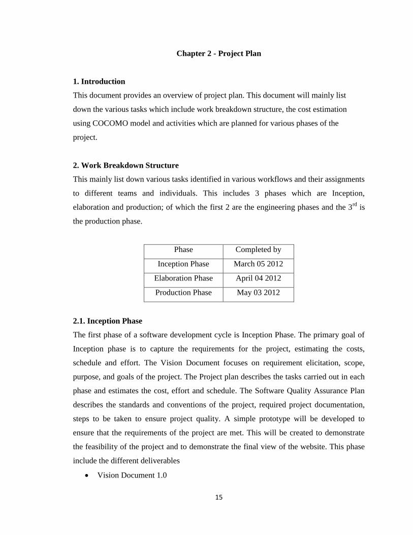
2. Work Breakdown Structure
This mainly list down various tasks identified in various workflows and their assignments
to different teams and individuals. This includes 3 phases which are Inception,
elaboration and production; of which the first 2 are the engineering phases and the 3rd
is
the production phase.
Phase Completed by
Inception Phase March 05 2012
Elaboration Phase April 04 2012
Production Phase May 03 2012
2.1. Inception Phase
The first phase of a software development cycle is Inception Phase. The primary goal of
Inception phase is to capture the requirements for the project, estimating the costs,
schedule and effort. The Vision Document focuses on requirement elicitation, scope,
purpose, and goals of the project. The Project plan describes the tasks carried out in each
phase and estimates the cost, effort and schedule. The Software Quality Assurance Plan
describes the standards and conventions of the project, required project documentation,
steps to be taken to ensure project quality. A simple prototype will be developed to
ensure that the requirements of the project are met. This will be created to demonstrate
the feasibility of the project and to demonstrate the final view of the website. This phase
include the different deliverables
Vision Document 1.0

16
Project Plan 1.0
Software Quality Assurance Plan
Workable Prototype
All these deliverables need to be approved by committee to move into the next phase of
project.
2.2. Elaboration Phase
The Second phase in the software development cycle is Elaboration Phase. The main idea
behind the elaboration phase is to develop an architectural design for the project. In this
phase, the architectural design will be documented using the applicable UML diagrams.
Each component will be documented at the interface level. Before starting Elaboration
phase, suggestions given by the supervisory committee at the end of Inception phase
should be carefully considered. According to the suggestions given by the supervisory
committee vision document and project plan document should be revised and then the
architecture design can be started. The Formal Requirement Specification is documented
as it helps in uncovering risks and making sure all requirements is captured. The Test
plan which documents all the testing activities should also be documented. The two
technical Inspectors will also perform an architectural review based on the checklist
given by the developer and then provide the feedback. This phase requires the following
deliverables.
Vision Document 2.0
Project Plan 2.0
Architectural Design
Test Plan
Formal Requirement Specification
Formal Technical Inspection Letters
Architecture Prototype
All these deliverables need to be approved by committee to move into the next phase of
project.
2.3. Production Phase

17
The main goal of the production phase is to implement and test the project. By the end of
this phase all the required documentation and the entire code should be constructed.
During this phase all the code of the project will be tested using the test plan documented
in the Elaboration phase. The test will be carried out to ensure that all the requirements
mentioned in the vision document 2.0 are met. Then the test results are analyzed and
documented. A User manual which contains the directions of using the website would be
created. This phase requires the following deliverables.
User Manual
Component Design 1.0
Source Code
Assessment Evaluation
Project Evaluation
References
Formal Technical Inspection Letters
Presentation 3
All these deliverables need to be approved by committee.
3. Cost Estimation
COCOMO
The COCOMO cost estimation method, abbreviated as The Constructive Cost Model is
developed by Barry W. Boehm and is used to estimate effort, cost and schedule for the
project. The effort and time can be estimated by the following equations:
Effort = C1 * EAF * (Size)P1
Time = C2 * (Effort)P2
Where:
Effort = number of person-months
Time = duration time in months for the project
C1= constant scaling coefficient of effort
C2= constant scaling for schedule

18
P1= exponent that characterizes the economics of scale inherent in the process
used to produce the end product
P2= exponent that characterizes the inherent inertia and parallelism in managing a
software development effort.
EAF= effort adjustment factor that characterizes the domain personnel,
environment, and tools used to produce the artifacts of the process.
Size= size of the end product, measured by the number of delivered source
instructions i.e. number of thousand source lines of code
There are three different development modes which include Organic, Semidetached and
Embedded modes. This project can be categorized under Organic mode as it is fairly
simple, developed by a single programmer and very flexible. As the project is in Organic
Mode
C1= 3.2
C2= 2.5
P1= 1.05
P2= 0.38
Therefore we calculate Effort and Schedule by following equations
Effort = 3.2 * EAF * (Size)1.05
Time = 2.5 * (Effort)0.38
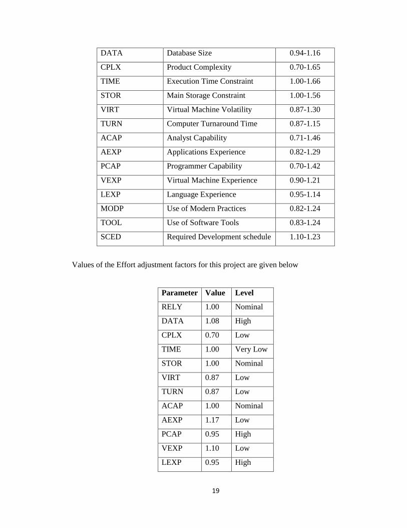
EAF Calculation
EAF, abbreviated as Effort Adjustment Factor is the product of the 15 adjustment factors
that normalizes the Effort. Each adjustment factor is classified as Very Low, Low,
Nominal, High, Very High or Extra High and the value of each adjustment factor lies
within specific range. So by knowing the calculation, value can be determined by also
considering the range which means the value falls within the range. The table below
shows the list of all the adjustment factors and their respective ranges.
Parameter Name Effort Adjustment Factor Value Range
RELY Required Reliability 0.75-1.40
19
DATA Database Size 0.94-1.16
CPLX Product Complexity 0.70-1.65
TIME Execution Time Constraint 1.00-1.66
STOR Main Storage Constraint 1.00-1.56
VIRT Virtual Machine Volatility 0.87-1.30
TURN Computer Turnaround Time 0.87-1.15
ACAP Analyst Capability 0.71-1.46
AEXP Applications Experience 0.82-1.29
PCAP Programmer Capability 0.70-1.42
VEXP Virtual Machine Experience 0.90-1.21
LEXP Language Experience 0.95-1.14
MODP Use of Modern Practices 0.82-1.24
TOOL Use of Software Tools 0.83-1.24
SCED Required Development schedule 1.10-1.23
Values of the Effort adjustment factors for this project are given below
Parameter Value Level
RELY 1.00 Nominal
DATA 1.08 High
CPLX 0.70 Low
TIME 1.00 Very Low
STOR 1.00 Nominal
VIRT 0.87 Low
TURN 0.87 Low
ACAP 1.00 Nominal
AEXP 1.17 Low
PCAP 0.95 High
VEXP 1.10 Low
LEXP 0.95 High
20
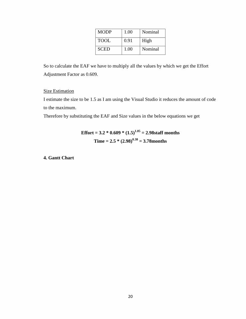
MODP 1.00 Nominal
TOOL 0.91 High
SCED 1.00 Nominal
So to calculate the EAF we have to multiply all the values by which we get the Effort
Adjustment Factor as 0.609.
Size Estimation
I estimate the size to be 1.5 as I am using the Visual Studio it reduces the amount of code
to the maximum.
Therefore by substituting the EAF and Size values in the below equations we get
Effort = 3.2 * 0.609 * (1.5)1.05
= 2.98staff months
Time = 2.5 * (2.98)0.38
= 3.78months
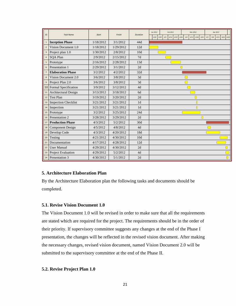
4. Gantt Chart
21
ID Task Name Start Finish DurationMar 2012Feb 2012 Apr 2012Jan 2012
1/22 4/13/25 4/152/121/29 4/224/83/112/262/19 3/4 3/18 4/29
1 44d3/1/20121/18/2012Inception Phase
2 12d1/29/20121/18/2012Vision Document 1.0
3 10d2/8/20121/30/2012Project plan 1.0
4 7d2/15/20122/9/2012SQA Plan
5 13d2/28/20122/16/2012Prototype
6 2d3/1/20122/29/2012Presentation 1
7 32d4/2/20123/2/2012Elaboration Phase
8 3d3/8/20123/6/2012Vision Document 2.0
9 3d3/8/20123/6/2012Project Plan 2.0
10 4d3/12/20123/9/2012Formal Specification
11 6d3/18/20123/13/2012Architectural Design
12 2d3/20/20123/19/2012Test Plan
13 1d3/21/20123/21/2012Inspection Checklist
14 1d3/21/20123/21/2012Inspection
15 24d3/25/20123/2/2012Prototype
16 2d3/29/20123/28/2012Presentation 2
17 30d5/2/20124/3/2012Production Phase
18 4d4/8/20124/5/2012Component Design
19 18d4/20/20124/3/2012Develop Code
20 10d4/30/20124/21/2012Testing
21 12d4/28/20124/17/2012Documentation
22 2d4/30/20124/29/2012User Manual
23 4d5/2/20124/29/2012Project Evaluation
24 2d5/1/20124/30/2012Presentation 3
2/5
5. Architecture Elaboration Plan
By the Architecture Elaboration plan the following tasks and documents should be
completed.
5.1. Revise Vision Document 1.0
The Vision Document 1.0 will be revised in order to make sure that all the requirements
are stated which are required for the project. The requirements should be in the order of
their priority. If supervisory committee suggests any changes at the end of the Phase I
presentation, the changes will be reflected in the revised vision document. After making
the necessary changes, revised vision document, named Vision Document 2.0 will be
submitted to the supervisory committee at the end of the Phase II.
5.2. Revise Project Plan 1.0

22
The Project plan 1.0 document will be revised and if necessary, the changes will be made
to the estimated Effort, size and cost. Also, the Gantt chart will be updated with the
changes in the schedule. If supervisory committee suggests any changes at the end of the
Phase I presentation, the changes will be reflected in the revised Project Plan document.
After making the necessary changes, revised Project Plan document, Project Plan 2.0
document will be submitted to the supervisory committee at the end of the Phase II.
5.3. Architectural Design 1.0
The complete project design will be documented with the applicable UML diagrams.
Each component in the architecture will be documented at the interface level. Then the
document would be submitted to the supervisory committee at the end of Phase II by
naming it as Architectural Design 1.0.
5.4. Developing Prototype
The Prototype of the project will be built by considering the requirements mentioned in
the Vision document 2.0. Then the prototype which finalizes the architectural baseline
would be submitted to the supervisory committee at the end of the Phase II.
5.5. Test Plan
A Test Plan will be developed to ensure that all requirements mentioned in the Vision
document 2.0 are satisfied in the project. The Plan will include the evaluation criteria for
all the critical use cases. Then the document will be submitted to the supervisory
committee at the end of Phase II for approval.
5.6. Formal Technical Inspections
The architectural design will be inspected by the two MSE students, Denise Case and Sri
Priya. The checklist will be provided by the developer and then the technical inspectors
go through the project based on the checklist and provide the feedback.
5.7. Formal Requirement Specification 1.0

23
The Object Constraint Language will be used to define and verify the formal
specification of the product.

24
Chapter 3 - Architecture Design
1. Introduction
This document provides an overview of Architecture design of New Vision Concept
School Portal. This document will mainly list down the various tasks which include
Architecture, UML diagrams, Technologies used to develop New Vision Concept School
Portal
2. Architecture
2.1. Technologies Used
User
Front End (Asp.net web forms &
Asp.net web user controls)
Business Logic
(C# Classes)
Back End
SQL Server 2008
Manage Database
Accesses
Database
Create and Edit
Webpages

25
Client Side
ASPX: ASP components are used in client side to display all the controls
HTML and CSS: CSS template is used for styling and HTML is used in
combination with CSS
JavaScript: few features were developed using JavaScript
Dreamweaver and Microsoft Front Page: used for developing most of the
pages as it would be easy to edit in future.
Server Side
C#: All the server side code is written in C#, which connects to the database
Database
SQL Server 2008: used to store all the information
IDE
Microsoft Visual Studio 2010
2.2. Project Architecture
26
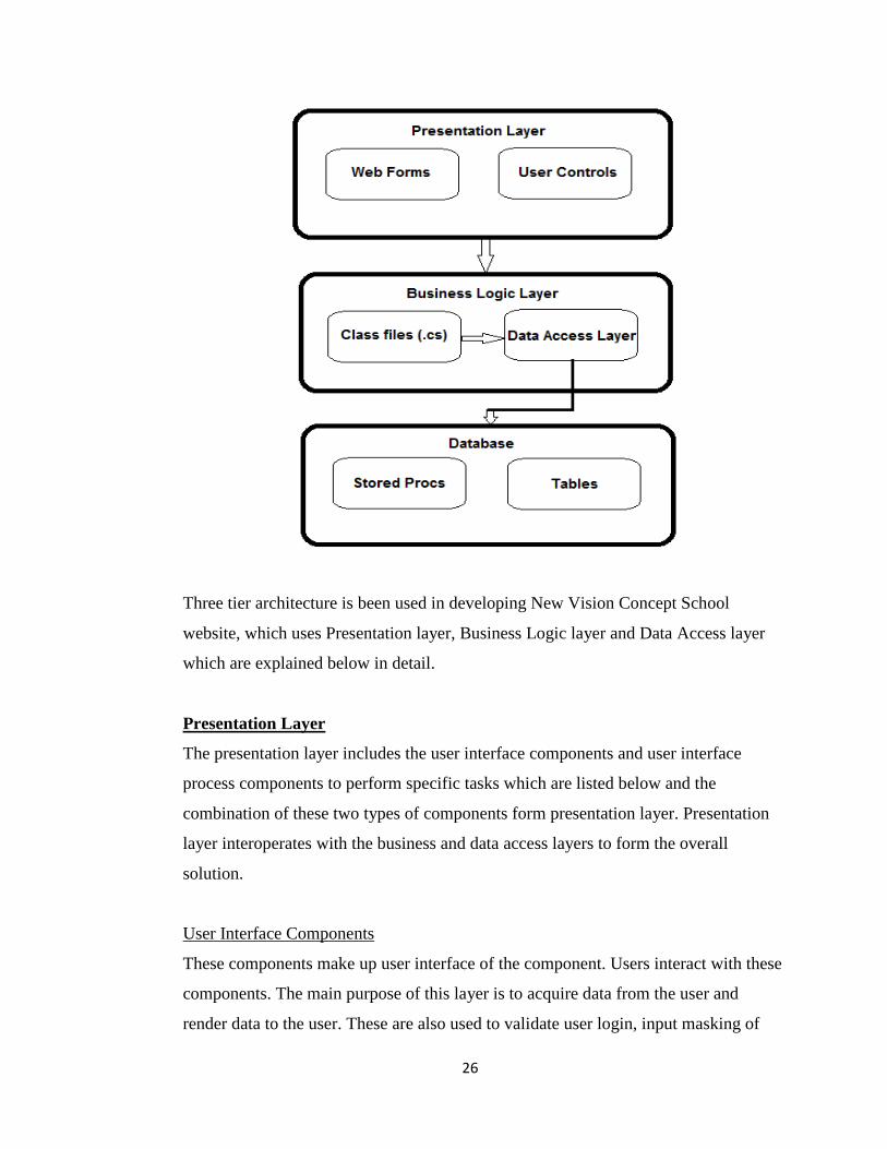
Three tier architecture is been used in developing New Vision Concept School
website, which uses Presentation layer, Business Logic layer and Data Access layer
which are explained below in detail.
Presentation Layer
The presentation layer includes the user interface components and user interface
process components to perform specific tasks which are listed below and the
combination of these two types of components form presentation layer. Presentation
layer interoperates with the business and data access layers to form the overall
solution.
User Interface Components
These components make up user interface of the component. Users interact with these
components. The main purpose of this layer is to acquire data from the user and
render data to the user. These are also used to validate user login, input masking of

27
the password and using appropriate controls to collect the input from the user such as
textboxes to enter the input, buttons to click so that they can view schedule. This
layer also involves managing the visual layouts, styles and general appearance of the
application. Also navigation from one page to other is being involved here.
Formatting and displaying data in different visual styles. Browsing and organizing
displayed data is also done in the presentation layer.
User interface process components
These elements control user interaction. Interface process components are not seen by
the user but they perform vital supportive role to user interface components. These
are mainly used for managing the control flow through user interface components like
separating the conceptual user interaction flow from the implementation or device
where it occurs and keep track of the progress of a user in a certain process.
ASP.net pages contain the pages which are viewable by the user. They are
responsible for separation for application logic and user interface. ASP.net pages
have the extension as .aspx. These pages contain the web controls of the application
and also the User Controls which are explained below.
User Controls
User controls are customized controls which can be created specific to the application
and are added to the .aspx pages. The extension of user controls is .ascx pages. In our
application we developed few features using user controls. User controls are easily
added to the web pages. Main usage of the user control is to modularize different
functionalities by using simple links. This finally results to the upgrading of
performance. Also makes the code manageable. User control can work as widgets and
can be made completely independent of the parent page. They speed up the
development process. The development is modularized which means there are
different functionalities available by using just a simple tag in your web page.
Business logic layer

28
This layer separates the business logic from other modules such as data access layer
and user interface. This can be advantageous as the business logic of an application
can often withstand modifications or replacements of the other two tiers. In detail, in
our application we have properly separated business logic layer and data access layer;
the data access layer could be rewritten to retrieve data from a different database,
without affecting any of the business logic. This helped us while developing the
application as we have split the layers and worked simultaneously.
Data access layer
This layer provides simplified access to data stored in persistent storage as in SQL
Server database. Data access layer returns a reference to object complete with its
attributes instead of row of fields from a database table. This helped the client
modules to be created with higher level of abstraction. This is handled by creating a
class of data access methods that directly reference a corresponding set of database
stored procedures. This helps to hide the complexity of the underlying data store from
the external world. Instead of using commands such as insert, delete and update to
access a specific table in a database, a class and a few stored procedures could be
created in the database. The procedures would be called from a method inside the
class, which would return an object containing the requested values. The insert, delete
and update commands are executed within simple functions which are stored within
the data access layer. Business logic methods are mapped to the database access
layer. Instead of making a query into a database to fetch all users from different tables
the application can call a single method from a DAL which abstracts those database
calls.
Database
SQL Server 2008 is used as a database in this project as it integrates well with visual
studio and provides good performance. Tables are physical storage for the data stored
in the database. All the operations utilizes database via stored procedures.
Stored Procedures

29
Stored Procedures are used to manipulate or operate data between tables. For
example, if there are three different queries we need to operate on three different
tables, they can be accommodated in one single stored procedure. Stored procedures
are always advantageous over in line queries as stored procedures are compiled when
created, but when a query is used, there is a database hit, which may degrade the
performance. And also because of modularity issues, if a same query has to be used
many number of times in the code, a stored procedure can be used. If there is an error
in the query or any change has to be made, then the fix has to be done in number of
places and also the code has to be deployed which may use lot of resources. Instead if
we are using a stored procedure, we can overcome the above issues. Stored
procedures also provide a measure of security as all parameters passed to a stored
procedure are type checked. Stored procedures in Oracle are saved in packages and
package bodies.
2.3. Flow Diagram of Website

30
3. UML Representation of the System
3.1. Class Diagram
The main classes considered in our application are User, Student, Teacher, Section,
Homework, Subject, Results, Balance Due, and Schedule. Each class has attributes
and operations.
Each class will have attributes, operations and role names mentioned in this diagram.
Attributes represent the type of the class. For example in New Vision Concept School
portal attribute of the subject is Subject Name which is String which means the name
of the subjects can be defined like Telugu, Hindi, English, Maths, Science, Social.
The operations are the tasks done by the class like for example in New Vision
Concept School portal there is operation named view schedule for student by which
student can perform the operation viewing the schedule.
The main classes are student and teacher. When Teacher updates the Homework and
Results the student can view them. The student can also view the schedule and
Balance Due when logged in to the student home page.

31
User: The user class is defined to make sure that all the users come under this
criterion like students, teachers.
Student: The Student class is defined to make sure that the all the aspects of student
are covered which means they need to have user id and password to login. They
should also be able to view the schedule, Balance Due, Homework and Results
Teacher: The Teacher class is defined to make sure that the all the aspects of teachers
are covered which means they need to have user id and password to login. They
should also be able to update the Homework and Results of the students
Balance Due: The Balance Due class consists of all the balance due of students.
Schedule: The Schedules class ensures that students can view their class schedule.
Section: The Section class consists of the student sections like it mentions which
student belongs to which section. This class has the attribute name Section name
where the names of the sections are defined.
Subject: The Subject class consists of the Subjects taken by the student. It has
attribute name Subject Name where names of the subjects are defined.
Homework: The Homework class is defined to make sure that student can view the
homework posted by the teacher.
Results: The Results class is defined to make sure that student can view the Results
posted by the teacher.
Contact Us/Feedback: This is a form where user can fill the form and click on the
submit button. The form will be sent as email to the directors email address.
32
3.2. Sequence Diagram
Sequence diagram is an interaction diagram that emphasizes the time ordering of
messages.
This is used to illustrate the dynamic view of a system. It models the control flow by
time ordering.
Fig 1 illustrates the login authentication of student and teacher. If the user enters the
login information it is authenticated using the user information which is stored in
database. After authentication if the username and password entered are correct the
login will be successful or else error message will be displayed.
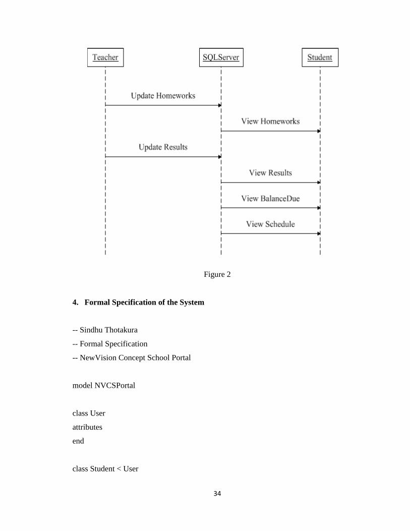
Fig 2 illustrates the message flow between Student, Teacher and Database. If Teacher
updates Homework and Results they will be stored in a database and for the students
to view the Homework and Results they will be retrieved from the database. Apart
from these students can also view the schedule and balance due information which
are retrieved directly from the database.

33
Figure 1
34
Figure 2
4. Formal Specification of the System
-- Sindhu Thotakura
-- Formal Specification
-- NewVision Concept School Portal
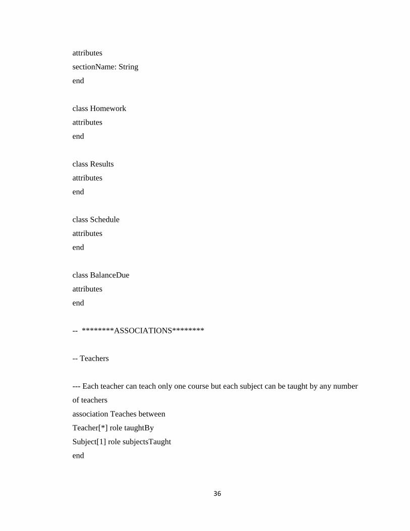
model NVCSPortal
class User
attributes
end
class Student < User

35
attributes
userid : String
password : String
operations
VerifyLogin(userid : String, password : String) : Boolean = Student.allInstances ->exists
(s : Student | s.userid = userid and s.password = password)
login() : Boolean
viewSchedule()
viewHomeworks()
viewBalanceDue()
viewResults()
end
class Teacher < User
attributes
userid : String
password : String
operations
VerifyLogin(userid : String, password : String) : Boolean = Teacher.allInstances ->exists
(t : Teacher | t.userid = userid and t.password = password)
login() : Boolean
updateHomeworks()
updateResults()
end
class Subject
attributes
subjectName: String
end
class Section
36
attributes
sectionName: String
end
class Homework
attributes
end
class Results
attributes
end
class Schedule
attributes
end
class BalanceDue
attributes
end
-- ********ASSOCIATIONS********
-- Teachers
--- Each teacher can teach only one course but each subject can be taught by any number
of teachers
association Teaches between
Teacher[*] role taughtBy
Subject[1] role subjectsTaught
end

37
--- Teachers can teach any number of Sections
association Assigned between
Teacher[*] role assignedTo
Section[*] role teach
end
-- Students
---Students enrolling into Subjects
association Taking between
Student[*] role enrolled
Subject[6] role have
end
--- Students enrolling in sections
association Enrolling between
Student[*] role contain
Section[1] role enroll
end
-- Homeworks
-- Teacher can update Homework
association UpdateHomework between
Teacher[*] role updated
Homework[*] role canUpdate
end
--- Student can view the Homeworks
association ViewHomework between
Student[*] role viewed

38
Homework[*] role viewUpdated
end
--- Homeworks are given to the Subjects
association giveHomework between
Homework[0..1] role has
Subject[*] role any
end
-- Results
--- Teacher can update Results
association UpdateResults between
Teacher[*] role updatedResults
Results[*] role canUpdateResults
end
--- Student can view the Results
association ViewResults between
Student[*] role viewedResults
Results[*] role viewUpdatedResults
end
--- Results are given to the Subjects
association giveResults between
Results[0..1] role display
Subject[*] role givenTo
end
-- Schedule

39
--- Student can view the Class Schedule
association ViewSchedule between
Student[*] role scheduleViewed
Schedule[*] role viewSchedule
end
-- Balance Due
--- Student can view the Balance Due
association ViewBalanceDue between
Student[*] role BalanceDueViewed
BalanceDue[*] role viewBalanceDue
end
--- ********CONSTRAINTS********
constraints
--- Every Student should have unique user name
context Student
inv uniqueUserid:
Student.allInstances -> forAll(s1, s2|s1<>s2 implies s1.userid <> s2.userid)
--- Every Teacher should have unique user name
context Teacher
inv uniqueUserid:
Teacher.allInstances -> forAll(t1, t2|t1<>t2 implies t1.userid <> t2.userid)
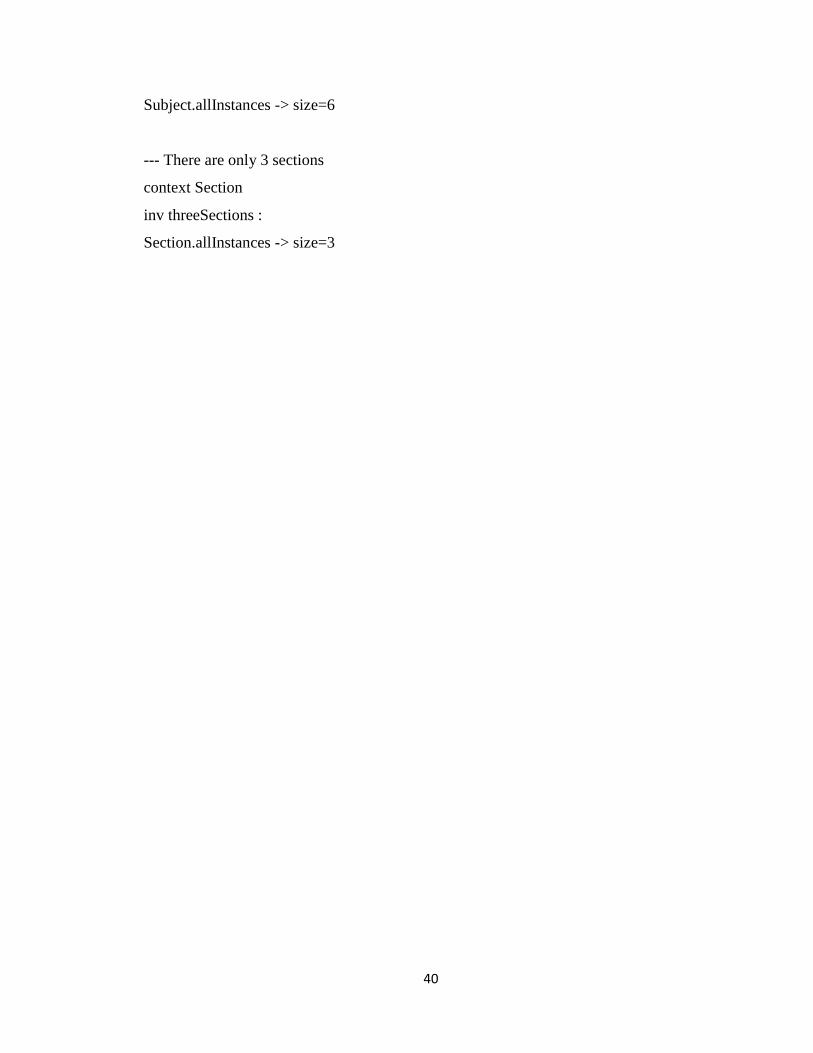
--- There are only 6 subjects
context Subject
inv sixSubjects :
40
Subject.allInstances -> size=6
--- There are only 3 sections
context Section
inv threeSections :
Section.allInstances -> size=3

41
Chapter 4 - Software Quality Assurance Plan
1. Purpose
Software Quality Assurance Plan defines the steps taken to ensure that the project is a
high quality product. This document lays foundation for reviewing and auditing the
software product and activities to verify that they comply with the applicable procedures
and standards. Managers of the project refer this document for monitoring the results of
the reviews and audits. It lists the tools and techniques used to develop the application.
2. References
1. Vision Document 1.0
2. Project Plan 1.0
3. IEEE Std. 730.1-1995, Guide for Software Quality Assurance Planning, IEEE,
1995.
4. IEEE Std. 730-1998, Standard Software Quality Assurance Plans, IEEE, 1998.
3. Management
3.1 Organization
The organization consists of supervisory committee, major professor, developer and two
formal technical inspectors.
3.1.1 Developer
Sindhu Thotakura
3.1.2 Major Professor
Dr. Mitchell Neilsen
3.1.3 Supervisory Committee
Dr. Mitchell Neilsen
Dr. Daniel Andresen
Dr. Gurdip Singh

42
3.1.4 Formal Technical Inspectors
Denise Case
3.2 Tasks
All tasks to be performed are documented in the Project Plan [2]. This might change after
the reviews from the supervisory committee.
3.3 Roles and Responsibilities
3.3.1 Developer
The developer will be responsible in developing all prototypes and documentation of
project during each phase. Developer is responsible to meet major professor on weekly
basis and discuss the progress of the project. In addition, the developer has to maintain
the webpage and include all the documents, time log and any other required information.
3.3.2 Major Professor
The major professor will be responsible in monitoring the overall progress of the project
and give the required guidance for the developer to successfully complete the project. He
is responsible to evaluate the work done by the developer on a weekly basis.
3.3.3 Supervisory Committee
The supervisory committee will be responsible for attending all three project
presentations by the developer. The committee will provide feedback and gives
suggestions at the end of each presentation by developer.
3.3.4 Formal Technical Inspectors
The formal technical inspectors will be responsible for conducting a formal inspection of
the project’s architectural design. A formal checklist will be provided to them by
developer by which they can review the design. After reviewing carefully, technical
inspectors will return a letter of inspection to the major professor and developer.

43
4. Documentation
All the project documentation will be posted on developer’s Webpage:
http://people.cis.ksu.edu/~sindhu85
4.1 Purpose
The project documentation will serve as the primary source of information about the
project. It also provides the information about the current state of project and also
developer can have all the records of the project to date.
4.2 Minimum Documentation Requirements
The documentation required for this project is listed on the MSE webpage:
http://mse.cis.ksu.edu/portfolio.html
Based on that minimum documentation required for the project are mentioned below
Phase I
Time Log
Vision Document 1.0
Project Plan 1.0
Software Quality Assurance Plan 1.0
Presentation 1
Phase II
Time Log
Vision Document 2.0
Project Plan 2.0
Formal Requirement Specification 1.0
Architecture Design 1.0
Test Plan
Technical Inspection Checklist
Presentation 2

44
Phase III
Time Log
User Manual
Component Design 1.0
Source Code
Assessment Evaluation
Project Evaluation
References
Formal Technical Inspection Letters
Presentation 3
5. Standards, Practices, Conventions, and Metrics
Documentation Standard:
The project documentation will follow the IEEE standards outlined in the Software
Quality Assurance standards [3], [4].
Coding Standard:
The project follows the ASP.NET standards for web part development and custom code
deployment.
Commenting Standard:
Each block of statements will be well commented. Comments are used in the project to
give a brief description of the code, mainly intended to describe the functionality and
purpose of commented areas.
Metrics:
COCOMO model is used to estimate the cost of the project in terms of effort and time.
6. Reviews and Audits
Reviews and Audits are mainly done by the supervisory committee. At the end of the
each phase of the project the developer is responsible to submit all the documents and
45
source code to the supervisory committee. Then the supervisory committee will evaluate
code and approve all the deliverables submitted by the developer at the end of each phase
of the project. In addition, the formal technical inspectors will be responsible to inspect
the architecture, design and source code to provide feedback about the project.
7. Testing
Test plan will be produced in the second phase of the project which includes all the
testing procedures applicable to the project.
8. Problem Reporting and Corrective Action
The developer will be responsible for requesting the guidance from the major professor
throughout the project. The major professor may report problems anytime during the
project but the supervisory committee will only report the problems at the end of the
presentation.
9. Tools, Techniques and Methodologies
The following are the tools, techniques and methodologies that will be used to develop
the project.
Technologies: C#, ASP.NET, HTML, CSS, JQuery, Microsoft SQL Server 2008
Documentation: Microsoft Office 2010(Word, Excel, PowerPoint), MS Visio
10. Records collection, Maintenance, and Retention
All the project deliverables and documentation will be stored locally of developer’s
machine and also published at the flowing Webpage:
http://people.cis.ksu.edu/~sindhu
11. Risk management

46
The developer will be responsible for identifying project risks and bringing them to the
attention of major professor. The major professor will then provide the guidance to
mitigate the risk.

47
Chapter 5 - Inspection Checklist
1. Introduction
This document provides a checklist to be used in the technical inspection of New Vision
Concept School Portal. It lays out broad guidelines for the technical inspectors to ensure
that the Architectural Design Document and the USE formal specification model are
complete, correct and consistent.
2. Items to be inspected
Technical inspectors refer Vision Document 2.0 for technical inspection.
1. System Architecture Design
a) Architecture Design
b) Class Diagram
c) Sequence Diagrams
2. Formal Specification
3. Formal Inspectors
Denise Case ([email protected])
SriPriya ([email protected])
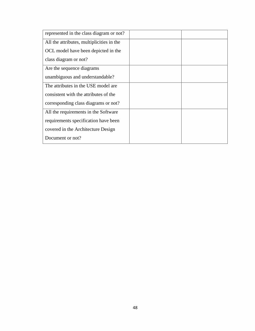
4. Formal Inspection List
Inspection Item Pass/Fail Comment
Do the symbols used in class diagram
conform to UML 2.0?
Do the symbols used in sequence
diagram conform to UML 2.0?
All the classes represented in the class
diagram are described in the
Architecture Document or not?
All the classes in OCL model are
48
represented in the class diagram or not?
All the attributes, multiplicities in the
OCL model have been depicted in the
class diagram or not?
Are the sequence diagrams
unambiguous and understandable?
The attributes in the USE model are
consistent with the attributes of the
corresponding class diagrams or not?
All the requirements in the Software
requirements specification have been
covered in the Architecture Design
Document or not?

49
Chapter 6 - Test Plan
1. Test Plan Identifier
New Vision Concept School Portal - Validation-V-1.0
2. Introduction
2.1 Objective
The main objective of the test plan for the New Vision Concept School Portal is to
specify the testing details of the use cases of the New Vision Concept School Portal. The
software project test plan also describes the objective, scope, approach, on identifying
and defining the test tools and Environment of the software testing effort for the New
Vision Concept School Portal.
2.2 Background
The main purpose of the project is to develop a website for New Vision Concept School
Portal. The users can browse the website based on the information needed and even they
can login into the website to view particular information. The test plan for this New
Vision Concept School Portal ensures that all the information is provided in a proper way
such that user can easily access it. Moreover each role has different levels of access to the
website and test plan has to layout criteria to test the content displayed to the user when
they login to the website is appropriate only to that particular role.
2.3 Scope
This test plan specifies the mechanisms that will be used to test the New Vision Concept
School Portal. This portal is categorized into three functional modules based on user
roles: Users, Students and Staff. Integration and System Testing will be performed to
verify the coupling and cohesion of Site and Sub-site hierarchy.
2.4 References
The following documents will be used as a reference for this test plan:
IEEE Standard for Software Test Documentation Std 829-1998
50
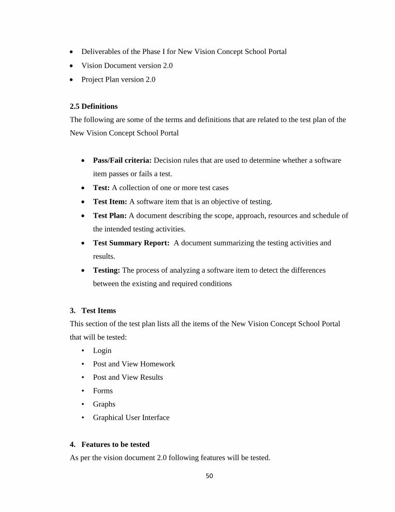
Deliverables of the Phase I for New Vision Concept School Portal
Vision Document version 2.0
Project Plan version 2.0
2.5 Definitions
The following are some of the terms and definitions that are related to the test plan of the
New Vision Concept School Portal
Pass/Fail criteria: Decision rules that are used to determine whether a software
item passes or fails a test.
Test: A collection of one or more test cases
Test Item: A software item that is an objective of testing.
Test Plan: A document describing the scope, approach, resources and schedule of
the intended testing activities.
Test Summary Report: A document summarizing the testing activities and
results.
Testing: The process of analyzing a software item to detect the differences
between the existing and required conditions
3. Test Items
This section of the test plan lists all the items of the New Vision Concept School Portal
that will be tested:
• Login
• Post and View Homework
• Post and View Results
• Forms
• Graphs
• Graphical User Interface
4. Features to be tested
As per the vision document 2.0 following features will be tested.
51
Users
SR1 – The user can view only one page at a time in the website.
SR2 – The user can register only if the user is either staff or a student who is studying
8th, 9th or 10th class.
SR3 – The users can send the feedback.
SR4 – The users should be able to contact the management using the contact form.
Students
SR5 – The student can view the individual results obtained during exams which are
posted by teacher.
SR6 – The student can view the class results which are posted by teacher.
SR7 – The student can view the Balance Due.
SR8 – The student can view the Class Schedule.
SR9 – The student can view the Homework posted by the teachers.
SR10 – The student can view the Comments posted by the teachers.
Teachers
SR11 – The teacher can update the results of the students.
SR12 – The teacher can write the comments about the students.
SR13 – The teacher can add or delete a student from the class.
SR14 – The teacher can post the Homework.
SR15 – The teacher can write the comments about the students.
SR16 – Appropriate graphs should be shown for the information.
5. Approach
This section of the test plan describes the overall approach for testing the New Vision
Concept School Portal. The types of testing carried out are Functional testing, usability
testing and compatibility testing. Apart from these, tools like JMeter and YSlow are used.
Functional testing tests whether the system satisfies the basic requirements listed in the
vision document. For each of these tests there will be pass/fail criteria which determines
whether the requirement is satisfied of not by the system. Usability testing is a quality
52
testing which determines the overall usability and user friendliness of the interface.
Compatibility refers to screen and different android device compatibility.
5.1 Functional Testing
The functional testing is mainly done on the whole integrated system to test functionality
and make sure that the project that has been developed meets all the requirements. The
test cases for the system testing will be the combination of unit and integration tests.
After conducting unit test module wise, Black Box Testing will be performed on the
system as a whole. Tester inputs data into the application and records the output from the
system.
5.2 Usability Testing
Six users will be asked to use the system, and give their feedback. Comments from the
users will be documented. Among these six users two will be the normal users, the other
two will be students and the remaining two will be staff. All these different kind of users
would be given the questionnaire in which users have to rate for the questions including
the easy and proper navigation, layout, visibility, layout, Going back to homepage from
any particular place, etc.
5.3 Compatibility Testing
In Compatibility Testing, the system is tested on different browsers which include
Internet Explorer, Mozilla Firefox, Google Chrome and Mac Safari. A Test Log will be
used for testing the different features in the three browsers. Results of the tests are
documented in the test log.
5.4 Performance Testing
Jmeter is used to test performance both on static and dynamic resources. It is mainly used
for Performance Testing, Load Testing and Stress Testing. It can be used to simulate a
heavy load on a server, network or an object to test its strength or to analyze overall
performance under different load types. It is used to make a graphical analysis of
performance or to test your server/script/object behavior under heavy concurrent load. It
53
can be used to simulate a heavy load on a server, network or an object to test its strength
or to analyze overall performance under different load types. It is used to make a
graphical analysis of performance or to test your server/script/object behavior under
heavy concurrent load.
5.5 Testing Tools
YSlow:
Yslow is used to analyze web page performance by examining all the components on the
page. It also examines components dynamically created by using JavaScript. It measures
page performance and offers suggestions for improvement.
6. Test Deliverables
• Test design specification
• Test case specification
• Test procedure
• Test Log
• Test summary report
Schedule
The testing is carried out at various phases of the project and the respective deliverables
for that particular phase. The test log will contain the record of all test cases along with
pass/fail status. If a test case fails it will be logged in the test log. The test log will also
contain the suggested solution for the failed test cases. Other independent test cases can
be run in parallel but the failed test cases are rerun after the possible workarounds are
carried out.
Software Development Lifecycle Phase Activity
Inception Phase Test plan proposed
Elaboration Phase Test plan approved and test cases are
designed.
Construction Phase Test case execution
54
Transition Phase Alpha and Beta level testing.
7. Environment
This section describes the necessary infrastructure required for the test environment for
the New Vision Concept School Portal
7.1 Hardware
The testing will be done in the Windows 7 laptop which has Microsoft Visual Studio
2010.
7.2 Software
• Operating system: The system will be tested in Windows 7.
• Databases: MS SQL Server 2005 is used to test content data & configuration data
of the website.
8. Pass or Fail Criteria
The test cases executed on the Airline Reservation System will pass if they meet the
specific requirements mentioned in the Vision document of the project. A test case is said
to fail, if the desired functionality is not satisfied by the system.
9. Suspension Criteria and Resumption Requirements
9.1 Suspension Criteria
Testing for all the dependent features will be suspended if a test case fails. The failed test
case will be logged onto the test log which contains the description for the error.
9.2 Resumption Requirement
The test cases which are not dependent on the case where the bug is reported will be
executed in parallel with the bug fixing. Once the failed test case has been taken note of
and has been identified and fixed then the testing for the failed test case will resume.

55
Chapter 7 - Assessment Evaluation
1. Introduction
This document primarily focuses on the summary of results of System Testing and
Performance testing performed during my MSE project. This document includes a test
analysis of the requirements satisfaction and performance of the system. The Test Cases
are in reference to the Test Cases defined in the Test Plan in phase-II.
2. Test Case Results Summary
The following table summarizes the test cases evaluated and the pass/fail result
Test Case # SR Tested Results/Comments
1 SR1 - User Login/Logout Pass
2 SR2 - Login Security Pass
3 SR3 - View Student Details Pass
4 SR4 – View Individual results Pass
5 SR5 – View Class results Pass
6 SR6 – View Balance Due Pass
7 SR7 – View Class Schedule Pass
8 SR8 – View Homework Pass
9 SR9 - Update Results Pass
10 SR10 – Post Homework Pass
11 SR11 – Feedback Pass
12 SR12 – Contact the management Pass
3. Test Case Analysis
3.1 User Login/Logout
The test case passed. The student and teacher can successfully login to their respective
homepages if they are authenticated by the server.
3.2 Login Security
56
The test case passed. The authentication and validation details of the student and teacher
can be managed successfully.
3.3 View Student Details
The test case passed. When the student enters into their home page the particular details
of student are displayed.
3.4 View Individual results
The test case passed. If the student is logged into the home page they are able to view
their individual results.
3.5 View Class results
The test case passed. If the student is logged into the home page they are able to view
their class results in graphical format.
3.6 View Balance Due
The test case passed. If the student is logged into the home page they are able to view
their respective balance due.
3.7 View Class Schedule
The test case passed. If the student is logged into the home page they are able to view
their respective schedule.
3.8 View Homework
The test case passed. If the student is logged into the home page they are able to view
their respective Homework.
3.9 Update Results
The test case passed. If the teacher is logged into the home page they can update the
results of all the students.

57
3.10 Post Homework
The test case passed. If the teacher is logged into the home page they can update the
Homework of all the students.
3.11 Feedback
The test case passed. The student and teacher can send the feedback directly to the
director in case they find any problems.
3.12 Contact the management
The test case passed. Any user can contact the management using the email ids provided
in the contact us page or fill the form which can be directly sent to director.
4. Performance Testing
Jmeter is used to test performance both on static and dynamic resources. It is mainly used
for Performance Testing, Load Testing and Stress Testing. It can be used to simulate a
heavy load on a server, network or an object to test its strength or to analyze overall
performance under different load types. It is used to make a graphical analysis of
performance or to test your server/script/object behavior under heavy concurrent load. It
can be used to simulate a heavy load on a server, network or an object to test its strength
or to analyze overall performance under different load types. It is used to make a
graphical analysis of performance or to test your server/script/object behavior under
heavy concurrent load.
Test Results
The results would show the response times as well as throughput, when increasing the
number of users accessing the application at the same time.
I have considered the pages which use less database hits in the page and compared results
with the pages which have more database content to be retrieved.
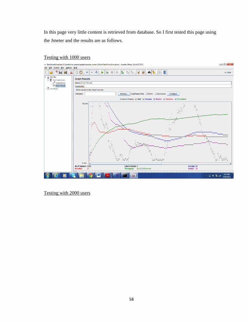
Campus News
58
In this page very little content is retrieved from database. So I first tested this page using
the Jmeter and the results are as follows.
Testing with 1000 users
Testing with 2000 users
59
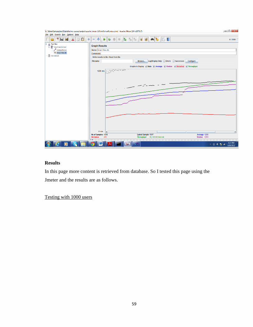
Results
In this page more content is retrieved from database. So I tested this page using the
Jmeter and the results are as follows.
Testing with 1000 users

60
Testing with 1500 users
61
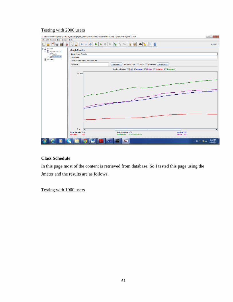
Testing with 2000 users
Class Schedule
In this page most of the content is retrieved from database. So I tested this page using the
Jmeter and the results are as follows.
Testing with 1000 users

62
Testing with 2000 users
Testing with 3000 users

63
We can see from the above graphs that throughput graph is stable for 1000 and 2000
users but the graph is not actually stable for 3000 users. Hence our application can
support around 2000 users.
5. Usability Testing
Six users will be asked to use the system, and give their feedback. Comments from the
users will be documented. Among these six users two will be the normal users, the other
two will be students and the remaining two will be staff. All these different kind of users
would be given the questionnaire in which users have to rate for the questions including
the easy and proper navigation, layout, visibility, layout, Going back to homepage from
any particular place, etc.
Questionnaire for Users
What do you think the purpose of the website is?
How is the organization of information?
How good is the terminology throughout the website?
Was it easy to get to the homepage from the page you started on?

64
Is it easy to read the characters on the page?
Does it showing proper error messages?
Are the Prompts of input clear?
How speed is website?
Did you find any broken links?
Was there something missing you was expecting to see?
What is your overall reaction to the website?
Results
I asked six users to fill the questionnaire by going through New Vision Concept School
website. Based on their comments I made few changes to the website.
6. Compatibility Testing
In Compatibility Testing, the system is tested on different browsers which include
Internet Explorer, Mozilla Firefox, Google Chrome and Mac Safari. The New Vision
Concept School Portal is compatible with all the four browsers, though Internet explorer
would be ideal to use as it is a Microsoft product for maximum efficiency in terms of
compatibility of all features.
7. Security Testing
The Authentication and Authorization validation for the students and teachers using New
Vision Concept School Portal is successfully tested.
8. Testing Tools
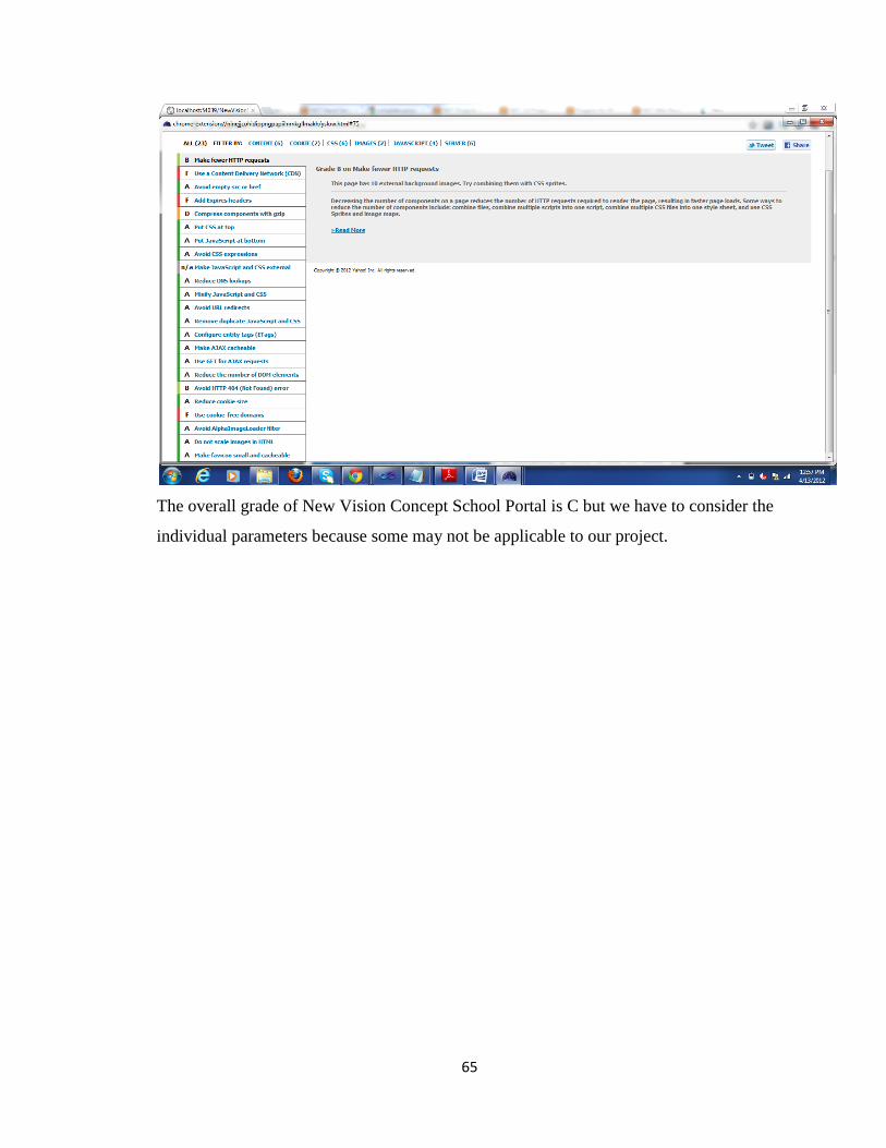
YSlow:
Yslow is used to analyze web page performance by examining all the components on the
page. It also examines components dynamically created by using JavaScript. It measures
page performance and offers suggestions for improvement.
When I tested New Vision Concept School Portal with YSlow I got the following
analysis.
65
The overall grade of New Vision Concept School Portal is C but we have to consider the
individual parameters because some may not be applicable to our project.

66
Chapter 8 - User Manual
1. Introduction
This document serves as a user manual for the New Vision Concept School Portal. It
explains us the step by step procedure to use the New Vision Concept School Portal.
2. Installation and Setup
2.1 Hardware Requirements
Front-end Web server and application server computers: a dual-processor
computer with processor clock speeds of 2.5-gigahertz (GHz) or higher and a
minimum of 2 gigabytes (GB) of RAM.
Back-end database server: a dual-processor computer with processor clock speeds
of 2.0 GHz or higher and a minimum of 2 GB of RAM.
2.2 Software Requirements
The required software for the New Vision Concept School Portal would be as follows:
Operating System: Microsoft Windows 7
Microsoft .NET Framework 4.0
Microsoft Visual Studio 2010.
Microsoft Internet Explorer (or) Mozilla Firefox (or) Google Chrome
Microsoft SQL server 2008
3. New Vision Concept School Portal Usage For Customers
3.1 Home Page
When the user opens the New Vision School Portal Website they can view the homepage
at the beginning and from there they can browse through different links which include
about us, Admissions, Academics, School Campus, Beyond Academics, Campus
Activities and Contact us. The user upon the information needed can browse through the
different pages and can view the information required. All the menu items will be
displayed at the top of the page and upon clicking the menu item the user will be directed
to that particular page and the information about that page will be displayed.

67
3.2 Login Feature
When the user clicks on the login button in the Home page of New Vision Concept
School Portal, the Student Login and Teacher Login would be displayed where the user
based upon student or teacher will enter the login information.

68
3.3 Student Home Page
When the Students enter the login information, they would be redirected to student home
page. The student name, section and balance due would be displayed on the home page.
In the home page there are links to view the class schedule, Homework, Results and
Class Results. If the student clicks on the links they would be redirected to their
respective pages and the information of particular student would be displayed.
3.4 Teacher Home Page
When the Teachers enter the login information, they would be redirected to teacher home
page. In the home page there are links to update Homework and Results of all students. If
the teacher clicks on the links they would be redirected to their respective pages where
they can edit the respective information.

69
3.5 View Class Schedule
When the students login into the page and click on View Class Schedule the student can
view their respective class schedule

70
3.6 View Homework
When the students login into the page and click on View Homework the student can view
their respective Homework for each subject
3.7 View Results
When the students login into the page and click on View Results the student can view
their respective results for each subject along with the total.

71
3.8 View Class Results
When the students login into the page and click on View Class Results the student can
view their Class Results in graphical format.

72
3.9 Update Homework
When the teachers login into their respective home page and click on update Homework
the teacher can update the homework based on the class and subject taught. To update the
homework, teacher should click on edit and change the homework and again click on the
update button.

73
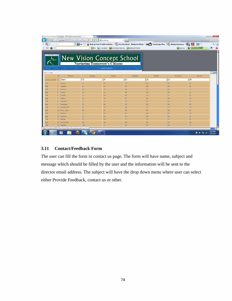
3.10 Update Results
When the teacher login into their home page and click on update Results, the teacher can
update the Results of each student. To update the Results, teacher should click on edit
and change the results of student and again click on the update button.
74
3.11 Contact/Feedback Form
The user can fill the form in contact us page. The form will have name, subject and
message which should be filled by the user and the information will be sent to the
director email address. The subject will have the drop down menu where user can select
either Provide Feedback, contact us or other.

75

76
Chapter 9 - Project Evaluation
1. Introduction
This document primarily focuses on the summary of my experiences during my MSE
project. This document includes a time log analysis (across all three phases), project
duration and SLOC analysis, the problems encountered and lessons learned. Last section
deals with the possible future work for the project.
2. Problems Encountered
This section describes the problems and difficulties encountered during the phases of my
MSE project.
2.1 Using Microsoft Visual Studio 2010
The first challenge I faced while doing the project is working with Microsoft Visual
Studio 2010 which I had never used before. It is challenging to learn the advanced
features of Microsoft Visual Studio 2010. Though SQL Server 2008 is integrated with
ASP.NET in Microsoft Visual Studio 2010, I found had few problems with the database
while establishing the connection to database as I did not find the proper instructions.
2.2 Determining the Requirements
As I am developing a website for school I have to compromise in some requirements
according to the requirements mentioned by the director of school
2.3 Role Play
Playing different roles at the same time as stakeholder, Programmer analyst, tester and
end-user was difficult.
3. Source Lines of Code
I estimated the number of source lines of code in New Vision Concept School Portal
using tool named SLOC Metrics. This tool estimates the number of source lines of code

77
in the given directory and produces the output in the form of excel, HTML and XML
document based on the output provided by the tool I estimated as follows
SLOC Generated = 2100
SLOC Written = 1000
SLOC Generated is the lines of code generated when I used the designer mode of
ASP.NET and Dreamweaver
SLOC Written is the lines of code I wrote.
4. Project duration
The below table show the start time and finish time of each phase of New Vision Concept
School Portal.
Phase Start Time Finish Time
Phase 1 Jan 18th
2012 Mar 1st 2012
Phase 2 Mar 2nd
2012 April 2nd
2012
Phase 3 April 3rd
, 2012 May 2nd
, 2012
Time Log Analysis:
Graphs below give a detailed analysis of the tasks carried out and the importance attached
to each task in the respective phase and the last graph gives detailed analysis of the time
allocated for tasks in overall project scenario. Overall Research & Reading, Coding,
Testing, Documentation took the major pie in the project task distribution chart as evident
in the figures.

78
Figure-1: Percentage time spent for activity in hours for phase 1
Figure-2: Percentage time spent for activity in hours for phase 2

79
Figure-3: Percentage time spent for activity in hours for phase 3
Figure-3: Percentage time spent for activity in hours for all phases
5. Experience Gained
This project was a great learning experience for me because of following reasons
80
It mainly it helped me to go through all the phases in software development life
cycle and going through the entire life-cycle of the software development has
gained me a lot of knowledge which would be very helpful in future.
In all my projects till now I have either taken up the front end or the back end but
this project helped to take the both front end and back end.
My desire to learn one of the fast evolving technologies like C#, .NET and SQL
Server has been satisfied.
This is the great opportunity for me to use Microsoft Visual Studio 2010 which
would be very helpful for me in future.
Through this project I understood that documentation is also important along with
coding and I understood the importance of determining requirements.
I have never gone through the testing phase but this project helped me to go
through testing phase and I learned different types of testing like performance
testing, system testing and tools like yslow.

81
References
1. IEEE Recommended Practice for Software Requirements Specification.
2. IEEE Std. 730.1-1995, Guide for Software Quality Assurance Planning, IEEE, 1995.
3. IEEE Std. 730-1998, Standard Software Quality Assurance Plans, IEEE, 1998.
4. Portfolio Requirements Page from CIS Webpage, Kansas State University.
5. Writing Hints by Dr. DeLoach
(http://people.cis.ksu.edu/~sdeloach/index.php?option=com_content&view=article&i
d=58&Itemid=92)
6. Wikipedia
7. MSDN ASP.NET Forums
8. http://www.cis.ksu.edu/mse
9. Alex Homer, Dave Sussman, Rob Howard, Brian Francis, Karli Watson and Richard
Anderson, Professional ASP.NET 1.1.
10. http://www.w3schools.com


