

North Slope of Alaska Facility Sharing Study
Prepared for
Division of Oil & Gas Alaska Department of Natural Resources
May 2004
By Bob Kaltenbach, Chantal Walsh, Cathy Foerster, Tom Walsh,
Jan MacDonald, Pete Stokes, Chris Livesey and Will Nebesky
www.petroak.com

ii
North Slope of Alaska Facility Sharing Study
Executive Summary
I. Introduction
II. Guiding Principles for Facility Sharing Practices
III. Physical Considerations
North Slope Overview
Projected Production and Pipeline Constraints and Excesses
Areas of Independents’ Interest and Activities
IV. Facility Sharing Negotiation Specifics
Guideline for Negotiation Strategy Template
Backout Methodology Guidelines
Backout Method alternatives
V. Commercial Considerations
Commercial Framework Existing North Slope Facility Sharing agreements
Kuparuk Endicott PBU and Pt Mac/Lisburne
Facility Sharing Analogs
North Sea’s Indicative Tariff Methodology Alberta’s Facility Sharing Agreement, the Jumping Pound Formula 90/95
Independent Oil Companies perspectives
VI. Recommendations
Appendices

iii
List of Figures Figure Page 1. North Slope Facilities Map* Facing page 8 2. Generic Processing Flow Schematic 8 3. Alpine Simplified Processing Flow 10 4 Badami Simplified Processing Flow 11 5 Endicott Simplified Processing Flow 12 6 Kuparuk Simplified Processing Flow 13 7 Milne Pt. Simplified Processing Flow 14 8 Northstar Simplified Processing Flow 16 9 North Slope Pipelines and TAPS* Facing page 19 10 Badami Pipeline shipping rates and capacity 20 11 Endicott Pipeline shipping rates and capacity 20 12 Milne Pt. Pipeline shipping rates and capacity 21 13 Alpine Pipeline shipping rates and capacity 21 14 Kuparuk Pipeline shipping rates and capacity 22 15 Northstar Pipeline shipping rates and capacity 22 16 TAPS Pipeline shipping rates and capacity 23 17 Recent North Slope exploration activity* Facing page 24 18 Hypothetical Backout Illustration* 34 19 Backout Concept 35 * Graphics created by Division of Oil and Gas

iv
List of Tables Table Page 1 Alpine facility operation vs. capacity 9 2 Badami facility operation vs. capacity 10 3 Endicott facility operation vs. capacity 12 4 Kuparuk facility operation vs. capacity 13 5 Milne Pt. facility operation vs. capacity 14 6 Northstar facility operation vs. capacity 15 7 Pt. McIntyre/Lisburne facility operation vs. capacity 16 8 Prudhoe Bay facility operation vs. capacity 17 9 North Slope pipeline capacities and future production 18 10 Summary of N.S. facility capacities and constraints 23 11 Example of Potential Costs 32

1
Executive Summary Facility sharing is critical for the future of the oil and gas industry on the North Slope.
This study was commissioned by the Alaska Department of Natural Resources, Division
of Oil and Gas to address issues associated with processing facility sharing agreements
for future North Slope activity. The goals are: to characterize the existing facilities, their
current throughput, and their theoretical capacities; to identify the needs and desires of
independent producers and North Slope facility owners and operators; to describe how
facility access is managed in other oil and gas provinces; and to develop guidelines for
facility access on the North Slope. Exploration and drilling activities are not addressed in
this study. Only issues related to facility sharing and availability of space in pipelines are
addressed in this report.
Petrotechnical Resources of Alaska (PRA) prepared this report by: compiling existing
facilities data from BP Exploration (Alaska), ConocoPhillips Alaska, and ExxonMobil;
identifying capacity issues; surveying independent oil companies; reviewing existing
facility sharing agreements; and preparing guidelines for third-party access to facilities.
While many North Slope processing facilities have spare capacity for oil, water, or gas
handling, most facilities have reached capacity for handling at least one of these
components. A summary of facility constraints and excess capacities at the field level
includes:
1. Alpine currently meets capacity for oil, gas, and water injection, and planned
facilities expansions likely will be filled by Alpine satellite development (Fjord,
Nanuk, etc).
2. Badami is in warm shutdown, and theoretically has space available up to design
capacities,
3. Endicott currently has spare oil capacity, but water and gas are at capacity limits,
4. Kuparuk currently has spare oil capacity, but water, total liquid and gas are at
capacity limits,
5. Milne Pt. has oil and gas capacity available through 2015, water capacity until 2011,
6. Northstar has capacity available in oil and water handling, and will reach gas capacity
by 2006,
7. Lisburne Production Center is currently at or near both gas and water capacity,
2
8. Prudhoe Bay facilities have room for oil, but gas production is at capacity limits and
water handling is at or approaching capacity limits in all facilities.
9. Pipeline capacity for Alpine is full; Kuparuk, Milne Pt, Northstar, and Lisburne/ Pt.
Mac are nearly full; and Badami, Endicott, and Prudhoe Bay have pipeline capacity
available.
The reference facility sharing agreement suggested herein by PRA is based largely on
Ballot No. 255 for Kuparuk, which has served as the standard for several subsequent
North Slope facility sharing agreements. The PRA reference agreement includes
examples of potential costs associated with facility access.
Only Kuparuk River, Prudhoe Bay, Lisburne, and Endicott production facilities have
existing facility sharing and services agreements addressing satellite production. The
existing facility sharing agreements, while created with only unitized production in mind,
are de-facto templates for recent access negotiations. The joinder agreement (Appendix
D) between Winstar and the Kuparuk River Unit is an example of the use of Ballots 255,
255A, and 260 for the Kuparuk River Unit allowing for third-party satellite production.
The guiding principles from the United Kingdom (U.K.) Code of Practice and Alberta’s
Jumping Pound formula have much in common with the existing North Slope facility
sharing agreements. However, the U.K. and Alberta contracts provide for regulatory
interdiction as needed to resolve disputes between negotiating parties, although emphasis
on a cooperative approach to facility sharing has been successful in negating the need for
government interdiction. Existing agreements between unit partners on the North Slope
present the starting point for new third-party facility sharing agreements, and an
understanding of these agreements will aid potential third-party producers in negotiating
new agreements.
A survey of 15 independent oil companies currently interested in Alaska oil and gas
exploration indicates that their primary concerns regarding access to existing facilities
include: backout calculations, access fee methodology, timeliness of access negotiations,
insurance requirements, and operatorship issues.
The report concludes that: 1. Interested parties should be able to negotiate an acceptable
agreement and negotiations should be initiated as early as prospect maturity allows; 2.
Development and communication of a process for facility access which is fair and
3
transparent will help to resolve any lack of trust, and create opportunity for expanded
resource development; 3. Potential third-party producers need to provide operators with a
well thought-out development plan and crude characteristics to support any request for
facility access; 4. Facility operators need to communicate the backout methodology and
terms, and respond to requests for access costs in a timely manner; 5. It must be
recognized that backout is a valid concept , representing real lost or deferred barrels to
the facility owners, for which reasonable compensation is justified; 6. Agreement must
be reached on a simplified backout methodology for fields without a detailed dynamic
plant model; and 7. The State of Alaska has options to help defray the impact of backout
fees, and this may prove to be a decisive factor in the success of North Slope facility
sharing.

4
North Slope of Alaska Facility Sharing Study
Introduction The State of Alaska, the North Slope operators and the companies having or seeking to
purchase leases on the North Slope all recognize the need for business cooperation and
efficient use of resources to maintain a vibrant North Slope oil and gas industry. The
continued and increased production of North Slope crude oil and gas is a goal of all
parties. This study addresses issues associated with the processing facility sharing
agreements for future North Slope activity. The study characterizes existing facilities and
their processing potential, identifies the needs and desires of independent oil and gas
companies and North Slope facility owners and operators, and lays the groundwork for
designing a template for successful facility access on the North Slope of Alaska which
benefits all parties involved.
PRA believes that there is mutual benefit to the facility owners and third-party producers
in adopting reasonable terms for facility access which are equitable and understandable.
In other mature basins, such as the North Sea, facility owners offer an “Indicative Tariff”,
or ballpark figure for facility access cost to interested producers. A survey of interested
independent oil and gas explorers was undertaken to gather their issues and concerns
about the future development in Alaska (Appendix A). The North Slope operators
responded to facility information and data request (Appendix B). PRA compiled these
various data and information in preparation for this report.
The list of deliverables provided is:
• Definition of existing facilities and design capacity for: Alpine, Badami,
Endicott, Kuparuk, Milne Point, Northstar, Pt Mac/Lisburne, and Prudhoe Bay
Fields.
• Identification of constraints and excess capacity for: Alpine, Badami, Endicott,
Kuparuk, Milne Point, Northstar, Pt Mac/Lisburne, and Prudhoe Bay Fields.

5
• Identification of facilities currently operating at capacity and areas that may need
higher capacity based on satellite exploration activity.
• Compilation and communication of the North Slope facility owners/operators
perspective on facility sharing.
• Assessment of facility sharing and back-out costs including a negotiation strategy
template, and a review of facility sharing agreements in other places.
• Compilation and communication of the current Independent oil companies’
perspective on facility sharing.
The issue of facility sharing is critical for the future of the oil and gas industry on the
North Slope. A successful facility sharing agreement must provide a solution that is
mutually satisfying to all parties. The existing owners and operators, the Independent
producers looking to be active on the North Slope, and the State of Alaska all have a
vested interest in seeing a process that enhances the oil and gas industry.
Potential producers have the burden of exploring and bringing the crude to the surface,
negotiating a facility sharing agreement for the processing of their fluids, and
transporting or establishing a custody transfer agreement at the outlet of the facility. The
exploration and drilling activities have their own significant challenges, which are not
addressed in this study. Only facility sharing issues and transportation issues, as they
relate to availability of space in pipelines and tankers, are addressed in this report.
The PRA team analyzing and reviewing this study included the following individuals:
Cathy Foerster Reservoir Engineer
Robert Kaltenbach Facility Specialist/Cost Analyst
Jan MacDonald Reservoir Engineer/Commercial Analyst
Chantal Walsh Petroleum Engineer
Tom Walsh Project Manager/Geophysicist
Pete Stokes Petroleum Engineer/Business Consultant
Chris Livesey Geologist

6
A tremendous amount of data and support to this study was provided by the North Slope
Facility Owners and Operators: BP Exploration (Alaska) Inc., ConocoPhillips Alaska,
Inc., and ExxonMobil. Additionally, the following Independent Oil companies submitted
valuable insight and ideas to this evaluation: Winstar, Talisman, Alaska Venture Capital
Group, Kerr McGee, and DevonCanada.
Guiding Principles for Facility Sharing Practices Facility sharing is a key component in the future viability of the oil and gas industry on
the North Slope and in order for successful sharing to take place, real mutual benefit to
all parties must be demonstrated. Given the complexity of the business drivers
represented by the parties, demonstration of mutual benefit is not a trivial exercise and it
is helpful to define a basic set of guiding principles for facility sharing on which all
parties can agree. Below is a list of guiding principles compiled from oral and written
communication from a cross-section of contributors to this study, including facility owner
and operator companies, potential third-party producers, and State of Alaska government
officials.
The facility sharing process must:
• Be fair, equitable, and understandable to all parties
• Result in net increase in production, improve resource conservation, and reduce waste
• Not result in any new government regulation
• Preserve and promote operational integrity
• Preserve the integrity of unit rights/obligations, and tax partnerships
• Reduce financial and operational risk
• Introduce no significant adverse impact to existing production
• Provide timely access to indicative fee structure for bona fide inquirers
• Create a level playing field for all producers, where the “best” barrels are produced
• Allow for resolution of conflicts
• Compensate the facility owners for their historical capital costs and lost or deferred production
• Provide equitable sharing of ongoing costs among all users

7
Physical Considerations Potential producers are faced with the burden of exploring for oil and gas, bringing it to
the surface, processing their fluids either with their own facilities or negotiating a facility
sharing agreement, and transporting or establishing a custody transfer agreement at the
outlet of the facility. If the third party producers build their own processing facilities, the
product stream will need to tie into a pipeline for transportation. The common carrier
pipelines will accept the production as long as it meets their specifications.
The North Slope processing facilities have specific design capacity limits, indicating the
amount of oil, water and gas which can be handled by the facility. If the handling
capacity of one of these streams is reached for a given facility, it limits the overall
production output from that facility. While some facilities may be producing below
capacity for oil, they are often limited due to capacity constraints on total water
production or gas production. In this case, additional production can be introduced into
the facility by backing out existing wells, such as those with high GOR or WOR, and
processing third party production of oil with lesser amounts of water and/or gas. The
facility-owner’s production volume that is deferred due to the introduction of third party
processing is referred to as “backout” or “backout volume”. Compensation for this
backout volume is an item of particular interest in negotiating a facility sharing
agreement. The method of calculating this backout volume is detailed later in the report.
Where facilities are producing at peak oil handling capacity, backing out high GOR or
WOR oil will not result in additional oil production, and backout costs for satellite
producers would be prohibitive. Additionally, the pipelines necessary for transporting
the produced fluids must have room for additional volume if new production is to be
introduced. It is essential to remember that, even if there is available processing capacity
in the facilities, there must be room for additional oil in the downstream pipeline system
to accommodate satellite production. (See section on pipeline volume and forecasts.)
The first step toward understanding the North Slope facility sharing issues is to identify
the processing infrastructure associated with each field and the design capacities of these
facilities. The next step is to review, by processing facility, the constraints which drive
the capacity limits. The North Slope processing facilities represent a complex network of
systems with strong interdependencies. Facility operators are continually optimizing
8
production parameters to maximize sales oil volume and minimize cost, managing
individual well production for hundreds of wells to match plant specifications and
pipeline and tanker capacities. To understand how and where third party oil can be
processed, all of these factors need to be considered.
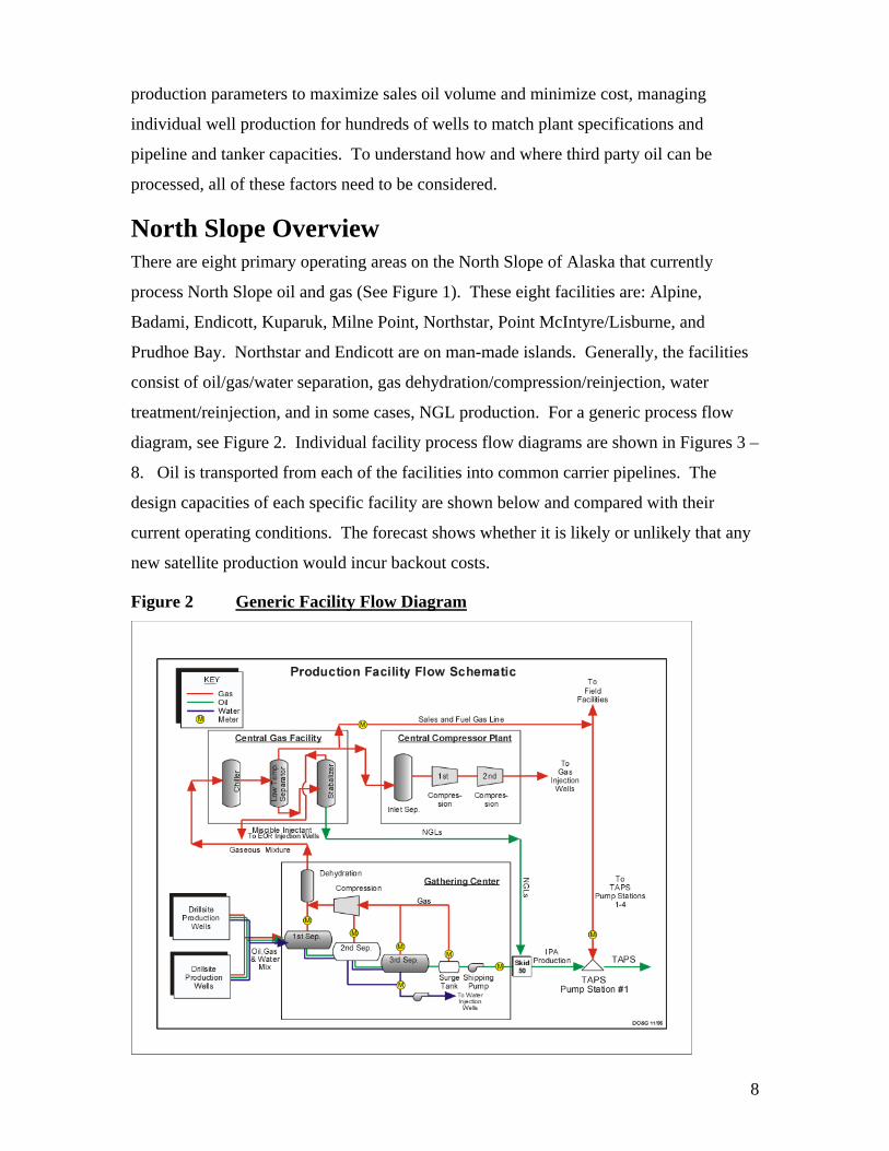
North Slope Overview There are eight primary operating areas on the North Slope of Alaska that currently
process North Slope oil and gas (See Figure 1). These eight facilities are: Alpine,
Badami, Endicott, Kuparuk, Milne Point, Northstar, Point McIntyre/Lisburne, and
Prudhoe Bay. Northstar and Endicott are on man-made islands. Generally, the facilities
consist of oil/gas/water separation, gas dehydration/compression/reinjection, water
treatment/reinjection, and in some cases, NGL production. For a generic process flow
diagram, see Figure 2. Individual facility process flow diagrams are shown in Figures 3 –
8. Oil is transported from each of the facilities into common carrier pipelines. The
design capacities of each specific facility are shown below and compared with their
current operating conditions. The forecast shows whether it is likely or unlikely that any
new satellite production would incur backout costs.
Figure 2 Generic Facility Flow Diagram
9
Alpine
There is currently one producing pool (Alpine Participating Area) in the Colville River
Unit (CRU). The major components of the basic facilities used by the CRU are: Alpine
Processing Facility, Two Drillsites (CD-1 and CD-2), Alpine Pipeline, Seawater
Treatment Plant (STP) pipeline, (Under a special agreement, STP supplies waterflood
water to the CRU), the Alpine Main Camp, Spill Response Center, Warehouse, Airstrip,
diesel supply line, roads and pipelines, and one Class 1 non-hazardous waste disposal
well.
Oil processing at Alpine consists of 2 stages of 3-phase separation and a dehydrator to
remove water to sales oil quality. Produced water is re-injected into injection wells at
drillsite CD-1 (Colville Delta-1). Produced gas is compressed (through four stages) and
flows into the gas injection header system. Gas is taken and mixed with indigenous
natural gas liquids (NGLs) to form miscible injectant (MI). The MI is distributed to
water-alternating-gas (WAG) injection wells at CD-1 and CD-2. Injection water consists
of produced water and seawater from the Seawater Treatment Plant (STP).
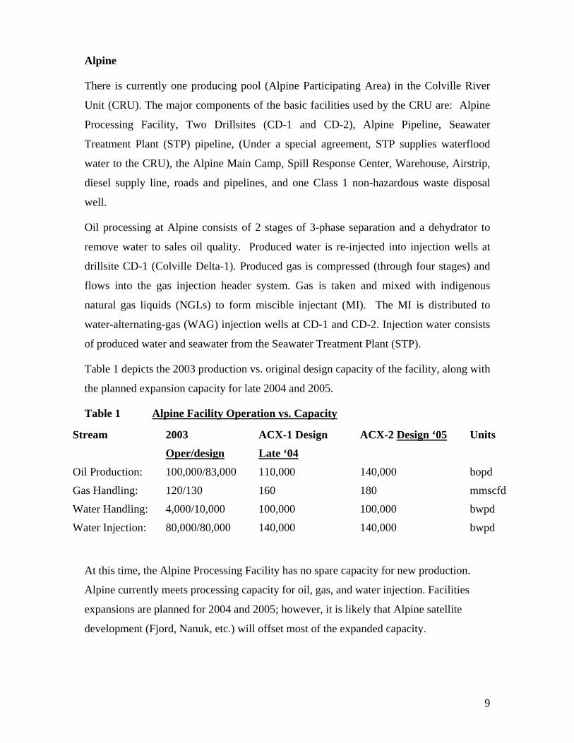
Table 1 depicts the 2003 production vs. original design capacity of the facility, along with
the planned expansion capacity for late 2004 and 2005.
Table 1 Alpine Facility Operation vs. Capacity
Stream 2003
Oper/design
ACX-1 Design
Late ‘04
ACX-2 Design ‘05 Units
Oil Production: 100,000/83,000 110,000 140,000 bopd
Gas Handling: 120/130 160 180 mmscfd
Water Handling: 4,000/10,000 100,000 100,000 bwpd
Water Injection: 80,000/80,000 140,000 140,000 bwpd
At this time, the Alpine Processing Facility has no spare capacity for new production.
Alpine currently meets processing capacity for oil, gas, and water injection. Facilities
expansions are planned for 2004 and 2005; however, it is likely that Alpine satellite
development (Fjord, Nanuk, etc.) will offset most of the expanded capacity.

10
Figure 3 Alpine Simplified Process Flow Diagram
Badami
The Badami Field is currently in a warm shutdown. The production facilities consist of
multi-stage oil/water/gas separation, water injection, gas treatment, compression and
injection, and oil export facilities. A WAG injection and lift gas system are also in place
at Badami.
Access to the Badami facilities is by barge, ice road, rolligon, or air. Peripherals are an
airstrip, a dock, a Class 1 non-hazardous waste disposal well, a grind-and-inject disposal
well, and a source for electricity.
Table 2 Badami Facility Operation vs. Capacity
Stream Operation/Capacity Units Oil Production: 0/35,000 bopd
Gas Handling: 0/25 mmscfd
Water Handling: 0/12,000 bwpd
Water Injection: 0/30,000 bwpd

11
Since Badami is in warm shutdown, there is theoretically space available up to the
capacities shown. There may be additional costs associated with startup but there should
not be any backout charges for processing here.
Figure 4 Badami Simplified Process Flow Diagram
Endicott
The Endicott facility consists of two man-made gravel islands located in the Beaufort
Sea. Produced gas is separated from the crude oil and processed to remove NGLs. The
NGL volumes are injected into the dry oil sales line subject to capacity available with
existing pipeline vapor pressure specifications. NGLs not sold are blended to create a
miscible injectant (MI) that is used in a water-alternating-gas enhanced oil recovery
project. Any residual gas is reinjected into the reservoir to provide pressure support, used
for fuel, or routed to the gas lift system to provide artificial lift. Produced water is treated
before being reinjected into the reservoir. Seawater can also be treated before being
injected.
Endicott’s two gravel islands are connected to each other, and linked to land by a gravel
causeway.

12
Table3 Endicott Facility Operation vs. Capacity
Stream Operation/Capacity Units Oil Production: ~25,000/115,000 bopd
Gas Handling: ~455/455 mmscfd design
Water Handling: ~210,000/225,000 bwpd design estimate.
Water Injection ~245,000/245,000 bwpd design estimate.
There currently is spare oil capacity at Endicott, but water and gas are at capacity limits.
Any new production would likely result in some backout.
Figure 5 Endicott Simplified Process Flow Diagram
Kuparuk
The Kuparuk facilities consist of three Central Processing Facilities (CPF).
The production facilities consist of multi-stage oil/water/gas separation, water injection,
gas treatment, compression and injection, and oil export facilities. There is a seawater
treatment plant designed to prepare seawater for waterflood operations.
Access to Kuparuk is by a gravel spine road. Other facilities include a construction
camp, spill response center, industrial center, warehouse, airstrip, topping plant and
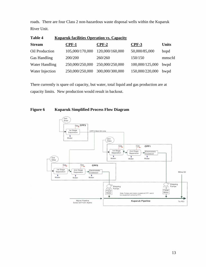
13
roads. There are four Class 2 non-hazardous waste disposal wells within the Kuparuk
River Unit.
Table 4 Kuparuk facilities Operation vs. Capacity
Stream CPF-1 CPF-2 CPF-3 Units Oil Production 105,000/170,000 120,000/160,000 50,000/85,000 bopd
Gas Handling 200/200 260/260 150/150 mmscfd
Water Handling 250,000/250,000 250,000/250,000 100,000/125,000 bwpd
Water Injection 250,000/250,000 300,000/300,000 150,000/220,000 bwpd
There currently is spare oil capacity, but water, total liquid and gas production are at
capacity limits. New production would result in backout.
Figure 6 Kuparuk Simplified Process Flow Diagram

14
Milne Point
The Milne Point Unit consists of a Central Facility Plant (CFP) and 12 producing /
injecting well pads. The production facility is designed to separate oil, gas and water.
After the gas is produced, it is compressed for gas injection and gas lift in the reservoir.
After processing, all of the produced water is injected into the reservoir. Artificial lift at
the Milne Point Field is a mix of ESPs, jet pumps and some gas lift, with ESPs being the
most prevalent. Two pipelines transport liquids to and from Milne Pt. (NGL northbound,
and oil southbound).
A permanent camp facility for up to 306 personnel is available. MPU currently utilizes
~40% of the space most of the time (~110 personnel). Transportation to and from Milne
is by gravel road.
Table 5 Milne Point Facility Operation vs. Capacity
Stream Operation/Capacity Units Oil Production: ~58,000/75,000 bopd
Gas Handling: ~40/42 mmscfd design estimate.
Water Handling: ~47,000/80,000 bwpd design estimate.
Milne Point has oil capacity available up to 12,000 bpd, and gas capacity available up to
2 mmscfd through 2015. In 2011, the water capacity is expected to be reached.
Figure 7 Milne Point Simplified Process Flow Diagram
8" 9,000 ft
Gas InjectionCompression
8 MMCFD
Back-upFuel Gas (E-3)
Fuel GasAssist Gas
GasDehydration
Gas LiftCompression42 MMCFD
Third StageCompression
Second StageCompression
Mod 48NGL Pump
IWAG 1 & 218 MMCFD (Each)
Crude ShippingPump
70 MBPD
Crude Cooling
'A' TrainTreater
40 MBPD
'A' SecondStage Separator
40 MBPD
'B' TrainTreater
60 MBPD
'B' SecondStage Separator
60 MBPD
Crude H
eating80 M
BPD
Slugcatcher100 M
BOPD
100 MBW
PD
MOD 68
Produced WaterSurge Drum
Source WaterSurge Drum
SourceWells
Water Pump? MBPD
HydrocycloneDesander &
Deoiler
Injection Suction Drum
Water Injection Pum
ps80 to 100 M
BPD
Booster Pumps? MBPD
E
E-3Lean Gas Injection Well
3" 2,180 Ft
C
C Pad Gas Lift
6" 18,000 ft
B B Pad Gas Lift6" 9,000 ftFirst Stage
Compression
6" ?? ft
8" ?? ft
6" ?? ft
L F
14" 54,910 ft
E Pad WAG
8" 17,000 ft 8" 5,500 ft
C Pad WAG
L F14" 17,000 ft 14" 5,500 ftC14" 18,000 ft
B14" 9,000 ft
J
I
SKUD Pump?? MBPDTo Jet Pumps
HG 8" 7,960 ft8" 4,170 ft
E K
S12" 17,025 ft
14" 22,200 ft
10" 10,500 ft14" 5,250 ft
14" 2,180 ft
Tract 14 Intersection
B
8" 2,180 ft E
L F6" 17,000 ft6" 5,500 ft8" 5,500 ft10 MBPD
C
F Pad SourceWater Injection
Booster Pump20 MBPD
To Injectors& Jet Pumps
8" 3,630 ft
8" 18,000 ft
J
I
HG 6" 7,960 ft6" 4,170 ft
K6" 3,630 ft
K Pad SourceWater Injection
Booster Pump?? MBPD6" 10,500 ft Booster Pump
0 MBPD
S8" 21,070 ft
MICrude Gas Water InjectionGas
NGL

15
Northstar The Northstar facilities are on Seal Island, located 6 miles offshore of the Point
Storkerson area in the Alaskan Beaufort Sea. Seal Island is a gravel island of
approximately 5 acres. Two pipelines transport hydrocarbons to and from the Northstar
Unit. The pipelines include one 10-inch common carrier pipeline from Seal Island to
Pump Station No. 1 to transport the sales oil to TAPS. The second 10-inch pipeline is to
import gas from the Central Gas Facility in the Prudhoe Bay Unit. The production
facility is designed to separate oil, gas and water. Produced water is processed and
disposed of into a Class 1 waste disposal well (there are two on the island). Following
dehydration and NGL removal, produced gas is injected into the reservoir. Sales oil is
cooled to Northstar export pipeline specification and shipped to TAPS. At the Pump
Station No. 1 end of the export line, the sales oil is re-heated to TAPS specifications.
A permanent camp facility for up to 74 production and drilling personnel is also installed
on the island. Multiple modes of transport are utilized depending on the season: an ice
road during winter; barge, hovercraft and helicopter transport during summer; and
helicopter and hovercraft transport during broken ice.
Table 6 Northstar Facility Operation vs. Capacity
Stream Operation/Capacity Units Oil Production: ~65,000/77,000 bopd
Gas Handling: ~410/500-555 mmscfd design estimate.
Water Handling: ~7,500/30,000 bwpd design estimate.
Combined Water and Oil limit ~70,000/85,000 bfpd design estimate
Northstar will have capacity available in oil and water handling but is expected to reach
gas capacity by 2006.

16
Figure 8 Northstar Simplified Process Flow Diagram
Point McIntyre/Lisburne
The Lisburne Production Center (LPC) consists of multi-stage oil/water/gas separation,
water injection, gas treatment, compression and injection, NGL production facilities, and
oil export facilities. The LPC also generates electric power.
The Pt. Mac/Lisburne facility has no camp. It houses personnel at the nearby Prudhoe
Bay Main Construction Camp. Access to and from Point McIntyre/Lisburne is by gravel
roads.
Table 7 Pt. McIntyre/Lisburne Facility Operation vs. Capacity
Stream Operation/Capacity Units Oil Production: ~60,000/205,000 bopd
Gas Handling: ~375/470 mmscfd design
Water Handling: ~140,000/160,000 bwpd design estimate
The facility is currently at or near both gas and water capacity. New production would
result in some backout.
Gas Injectors
Oil Producers

17
Prudhoe Bay
The Prudhoe Bay facilities, the largest on the slope, consist of six separate major
production processing centers with a central power station, central gas processing facility,
central compressor (injection) facility, two operating centers, a central seawater treatment
plant, a topping plant, and a plant to grind and inject drill cuttings. There is one grind-
and-inject well, and three Class 2 non-hazardous waste disposal wells. The production
facilities consist of multi-stage oil/water/gas separation, water injection, gas treatment,
compression and injection, NGL production and oil export.
The main housing facilities for the Prudhoe Bay Field are the Eastern Operating Camp
(EOC), the Western Operating Area Camp (BOC), and the Main Construction Camp
(MCC). In addition to these, there are a number of support camps throughout the field.
The PBU area can accommodate up to 963 people. (This figure does not include
accommodations in Dead Horse.)
Table 8 Prudhoe Bay Facility Operation vs. Capacity
Stream Operation/Capacity Units Oil Production: ~487,000/1,660,000 bopd
Gas Handling: ~8,700/8,700 mmscfd design estimate.
Water Handling: ~1,720,000/1,720,000 bwpd design.
There is room for oil, but gas production is at capacity limits and water handling is at or approaching capacity limits in all facilities. New production would result in some backout.
18
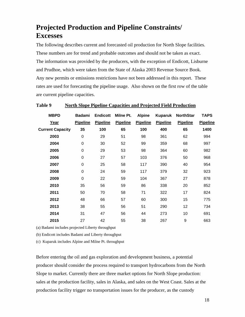
Projected Production and Pipeline Constraints/ Excesses The following describes current and forecasted oil production for North Slope facilities.
These numbers are for trend and probable outcomes and should not be taken as exact.
The information was provided by the producers, with the exception of Endicott, Lisburne
and Prudhoe, which were taken from the State of Alaska 2003 Revenue Source Book.
Any new permits or emissions restrictions have not been addressed in this report. These
rates are used for forecasting the pipeline usage. Also shown on the first row of the table
are current pipeline capacities.
Table 9 North Slope Pipeline Capacities and Projected Field Production
MBPD Badami Endicott Milne Pt. Alpine Kuparuk NorthStar TAPS
Year Pipeline Pipeline Pipeline Pipeline Pipeline Pipeline Pipeline
Current Capacity 35 100 65 100 400 65 1400
2003 0 29 51 98 361 62 994
2004 0 30 52 99 359 68 997
2005 0 29 53 98 364 60 982
2006 0 27 57 103 376 50 968
2007 0 25 58 117 390 40 954
2008 0 24 59 117 379 32 923
2009 0 22 59 104 367 27 878
2010 35 56 59 86 338 20 852
2011 50 70 58 71 322 17 824
2012 48 66 57 60 300 15 775
2013 38 55 56 51 290 12 734
2014 31 47 56 44 273 10 691
2015 27 42 55 38 267 9 663
(a) Badami includes projected Liberty throughput
(b) Endicott includes Badami and Liberty throughput
(c) Kuparuk includes Alpine and Milne Pt. throughput
Before entering the oil and gas exploration and development business, a potential
producer should consider the process required to transport hydrocarbons from the North
Slope to market. Currently there are three market options for North Slope production:
sales at the production facility, sales in Alaska, and sales on the West Coast. Sales at the
production facility trigger no transportation issues for the producer, as the custody
19
transfer is at the outlet flange of the facility. The other two options will entail the use of
one or more of the Common Carrier Pipelines in Alaska. These pipelines are regulated by
State and Federal Commissions. These pipelines will not discriminate between shippers,
but will prorate volumes if pipeline capacity is exceeded. Crude oil product must meet
certain specifications to be accepted by the pipeline.
The pipeline specifications for the oil delivery to PS1 are as follows:
• Maximum basic sediment and water (BS&W) content of 0.35%
• Minimum delivery temperature of 105o F to prevent paraffin deposition
• Maximum delivery temperature of 142o F
• Maximum True Vapor Pressure of 14.2 psia
The existing TAPS system can handle more than 1.4 million barrels of oil a day.
Alyeska Pipeline Services Company is currently evaluating a plan to redesign TAPS to
transport approximately 1 million bpd, expandable up to about 1.14 million bpd with drag
reducing agent.
These are only guidelines for capacity since the addition of drag reducing agent and
operational variation can change the overall capacity. If the amount of production
exceeds the capacity, the pipeline operators will reduce each producer’s rate on a prorated
basis until capacity is met. Therefore, new production going into a pipeline that is at
capacity will cause a reduction in existing production so that all producers can ship their
product. This production will not increase or decrease the total quantity, just redistribute
the production allocated to each producer.
Each pipeline has a group of owners that will transport fluids for a per barrel charge
(tariff). Transportation must be coordinated from point of production to market and may
involve several pipelines and different shippers. TAPS will transport the product to the
Port of Valdez. The product must be tanker transported from Valdez to the interstate
market.
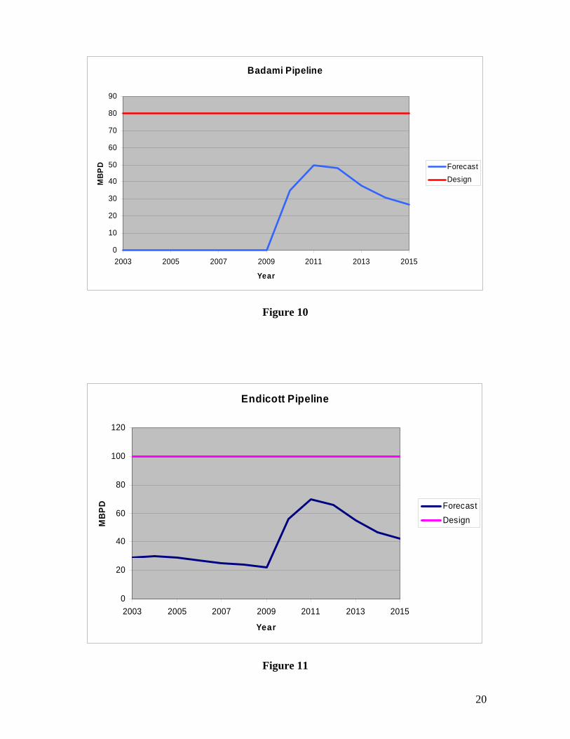
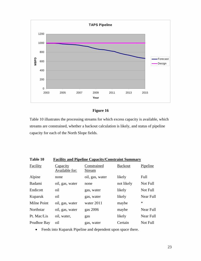
Figure 9 is a map of the North Slope pipelines and TAPS. Figures 10 - 16 are timelines
of the pipeline capacity and potential excess shipping space. These figures are based on
production profiles as shown in the State of Alaska 2003 Revenue Book and on
information provided by producers.
20
Badami Pipeline
0
10
20
30
40
50
60
70
80
90
2003 2005 2007 2009 2011 2013 2015
Year
MBP
D ForecastDesign
Figure 10
Endicott Pipeline
0
20
40
60
80
100
120
2003 2005 2007 2009 2011 2013 2015
Year
MB
PD ForecastDesign
Figure 11

21
Milne Point Pipeline
0
10
20
30
40
50
60
70
2003 2005 2007 2009 2011 2013 2015
Year
MB
PD ForecastDesign
Figure 12
Alpine Pipeline
0
20
40
60
80
100
120
140
2003 2005 2007 2009 2011 2013 2015
Year
MBP
D ForecastDesign
Figure 13

22
Kuparuk Pipeline
0
50
100
150
200
250
300
350
400
450
2003 2005 2007 2009 2011 2013 2015
Year
MBP
D ForecastDesign
Figure 14
NorthStar Pipeline
0
10
20
30
40
50
60
70
80
2003 2005 2007 2009 2011 2013 2015
Year
MB
PD ForecastDesign
Figure 15
23
TAPS Pipeline
0
200
400
600
800
1000
1200
2003 2005 2007 2009 2011 2013 2015
Year
MBP
D ForecastDesign
Figure 16
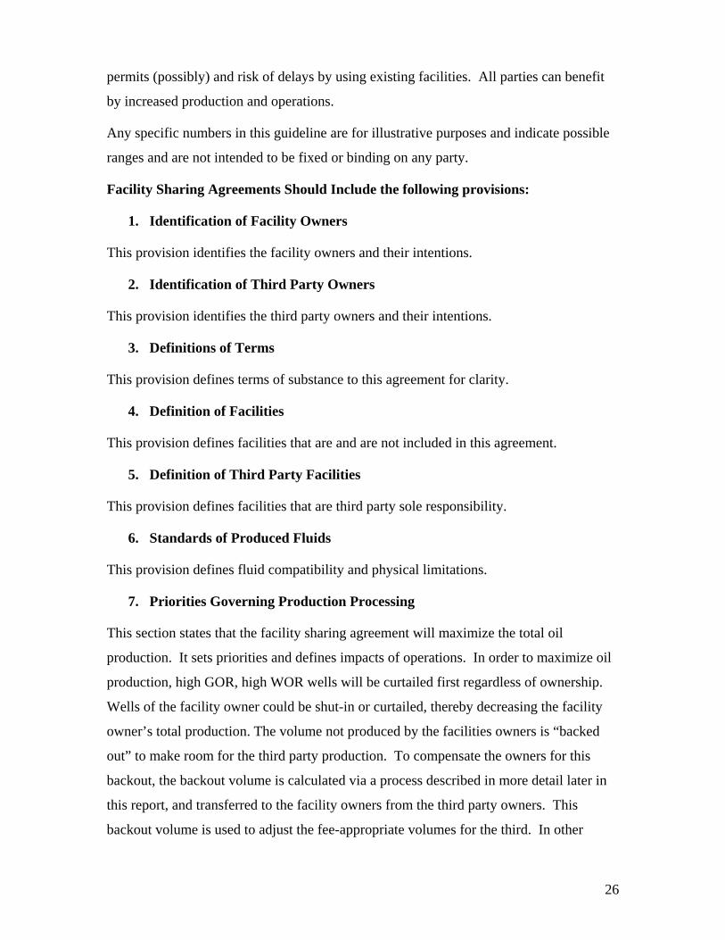
Table 10 illustrates the processing streams for which excess capacity is available, which
streams are constrained, whether a backout calculation is likely, and status of pipeline
capacity for each of the North Slope fields.
Table 10 Facility and Pipeline Capacity/Constraint Summary Facility Capacity
Available for: Constrained Stream
Backout Pipeline
Alpine none oil, gas, water likely Full
Badami oil, gas, water none not likely Not Full
Endicott oil gas, water likely Not Full
Kuparuk oil gas, water likely Near Full
Milne Point oil, gas, water water 2011 maybe *
Northstar oil, gas, water gas 2006 maybe Near Full
Pt. Mac/Lis oil, water, gas likely Near Full
Prudhoe Bay oil gas, water Certain Not Full
• Feeds into Kuparuk Pipeline and dependent upon space there.

24
Areas of Independents’ interest and activities Figure 17 is a map of recent (2001-present) North Slope exploration activity, including
recent exploration wells, unit boundaries, and recently acquired state leases. This map
portrays the areas of interest expressed by North Slope explorers through their lease
acquisitions and drilling activities, and indicates the areas most likely to put pressure on
existing infrastructure. Some of the activities which, given successful exploration
programs, will potentially impact the facility sharing landscape include:
1. Pioneer/Armstrong Oooguruk Unit evaluation
2. Kerr-McGee/Armstrong Nikaitchuq 2004 Exploration drilling
3. ConocoPhillips 2004 NPRA drilling
4. Pioneer 2004 lease acquisition
5. AVCG 2004 lease acquisition
6. Ultrastar 2004 lease acquisition
Pioneer and Armstrong partnered in 2003 to drill 3 exploration wells in the Oooguruk
Unit northwest of KRU (yellow leases). They have announced a discovery in the
Nuiqsut Fm., and are evaluating options for development of this discovery. This
potential development could impact KRU facilities and/or the Kuparuk Pipeline.
Kerr-McGee and Armstrong drilled two wells (Nikaitchuq #1&2) northwest of MPU
in 2004, and have announced a discovery in the Sag River Fm. Potential
development here could impact MPU facilities, the Milne Point Pipeline, and the
Kuparuk Pipeline.
ConocoPhillips has drilled a number of discovery wells to the west of CRU, all of
which figure to impact the Alpine facilities, Alpine Pipeline, and Kuparuk Pipeline.
Pioneer acquired tracts in the 2003 North Slope and Beaufort Sea Areawide Lease
Sales in the Hemi Springs area, as well as north of PBU, east of Northstar, and west
of Kuparuk. Successful exploration programs associated with these lease acquisition
could impact numerous production facilities.
AVCG added to their lease position in 2003 with acquisitions east and south of CRU,
north of PBU, and west of KRU. They are considering stand-alone processing

25
options at this time, which would limit the facility impact to common carrier
pipelines.
UltraStar Exploration added new leases to their portfolio in 2003 around Badami, and
north of PBU, and successful drilling of their prospects could impact Badami, Pt.
McIntyre/Lisburne and/or PBU facilities.
Most of the activity shown on the map is focused around existing facilities, with the
exception of SWEPI and Unocal’s lease acquisitions some 50 miles south of KRU,
and Total’s drilling nearly 50 miles west of CRU.
A critical constraint will be available processing and pipeline capacity to the west and
north of KRU. Alpine satellites, NPRA, and the Ooooguruk and Nikaitchuq
discoveries will all place significant pressure on the Kuparuk and Alpine pipelines.
However, with enough new production potential realized, additional pipeline capacity
may be justified.
Facility Sharing Negotiation Specifics Guideline for Negotiation Strategy Template PRA has put together a guideline for a facility sharing agreement based largely on Ballot
No. 255 for Kuparuk. This guideline deals with the technical and accounting aspects and
not the legal provisions of an agreement. All parties are advised to obtain legal counsel
to protect their rights and limit their liabilities.
This guideline’s purpose is to illustrate the anticipated components of a possible
agreement and the expected ranges of costs associated with key components. It is not
intended to be all inclusive. Every actual agreement will have its own particulars and be
specific to that situation. The key to an agreement is to establish fair terms for utilizing
existing infrastructure that provide third party owner(s) improved economics to develop
and produce from nearby fields or other commercial paying reservoirs while
compensating infrastructure owners for their existing investment, risk taking and
operations. The facility owners have incurred substantial risk and invested large capital
in their facilities. The third party owners can benefit from avoiding construction time,
26
permits (possibly) and risk of delays by using existing facilities. All parties can benefit
by increased production and operations.
Any specific numbers in this guideline are for illustrative purposes and indicate possible
ranges and are not intended to be fixed or binding on any party.
Facility Sharing Agreements Should Include the following provisions:
1. Identification of Facility Owners
This provision identifies the facility owners and their intentions.
2. Identification of Third Party Owners
This provision identifies the third party owners and their intentions.
3. Definitions of Terms
This provision defines terms of substance to this agreement for clarity.
4. Definition of Facilities
This provision defines facilities that are and are not included in this agreement.
5. Definition of Third Party Facilities
This provision defines facilities that are third party sole responsibility.
6. Standards of Produced Fluids
This provision defines fluid compatibility and physical limitations.
7. Priorities Governing Production Processing
This section states that the facility sharing agreement will maximize the total oil
production. It sets priorities and defines impacts of operations. In order to maximize oil
production, high GOR, high WOR wells will be curtailed first regardless of ownership.
Wells of the facility owner could be shut-in or curtailed, thereby decreasing the facility
owner’s total production. The volume not produced by the facilities owners is “backed
out” to make room for the third party production. To compensate the owners for this
backout, the backout volume is calculated via a process described in more detail later in
this report, and transferred to the facility owners from the third party owners. This
backout volume is used to adjust the fee-appropriate volumes for the third. In other

27
words, the third party owners do not pay fees on the barrels they must give up as backout
compensation
8. Produced Water and Seawater
Facility owners will provide to each third party a volume of water, for water injection,
that is equal to the volume of water delivered to the facilities by the third party
production facilities.
9. Excess Water Volumes
To the extent that additional produced water or seawater volumes are available and
desired, facility owners will provide third party facilities with water volumes in excess of
their water production where needed to maximize and optimize field development. A fee
may apply for this excess volume.
10. Facility Access Fees
The facility owners will be compensated for their investment and ongoing costs incurred
to provide facilities and processing of the third party fluids.
Capital Access Fee
This fee compensates the facility owners on an adjusted per barrel processed basis for
their past capital investment. This fee recognizes that the facility owners have invested
large sums in the past for the equipment and facilities that are available to the third party.
Generally this fee would have a depreciation component and a rate of return component.
Capital Access Fee Surcharge
This fee compensates the facility owners for capital costs incurred after third party
processing begins. This would apply if the third party did not participate in a joint capital
project but the third party benefits from the project. This fee could be a per barrel charge
and apply in capital increments. For example: a capital access fee of $0.025 per barrel
imposed following each $25 million increment of cumulative gross amounts expended on
joint capital projects and excess routine field CAPEX.
Abandonment Fee
This fee compensates facility owners for future abandonment costs that will be incurred
during the abandonment of the facilities.

28
Abandonment Fee Surcharge
This fee is to cover abandonment costs for capital added after third party processing
begins.
11. Accounting
For purposes of determining volumes of third party oil processed through facility
equipment, the volumes specified in the monthly production and injection reports filed
with the Alaska Oil and Gas Conservation Commission will be used less any adjustments
caused by backout. Allocation among the owners will be determined by the parties.
12. Operating and Maintenance Costs
The facility owners incur operating and maintenance costs for all of the facilities and
drillsites. The costs for any facilities not benefiting the third party facilities or production
shall be excluded from the calculations.
Plant Liquid Processing Fee
The per-barrel fee shall be determined by dividing the O&M costs by the volume of total
liquid production (oil plus water) processed in the facilities. The O&M costs can include
total plant labor, direct operating costs and allocated field support costs which are
attributed to gross liquid processing operations but do not include any O&M costs not
benefiting the gross liquid processing operations.
Plant Gas Processing Fee
The per-mcf fee shall be determined by dividing the O&M costs by the volume of total
gas production and lift gas processed in the facilities. The O&M costs can include total
plant labor, direct operating costs and allocated field support costs which are attributed to
gross gas processing operations but not include any O&M costs not benefiting the gross
gas processing operations. The fee shall be applied to the allocated volume of fuel gas,
flare gas, take-in-kind, shrinkage and lost gas attributable to third party fluids.
Common Drillsite
The per barrel fee shall be determined by dividing the O&M costs by the volume of total
liquid production (oil plus water) processed in the facilities. The O&M costs can include
total drillsite labor, direct operating costs and allocated field support costs which are

29
attributed to all drillsite operations but shall exclude charges for operations which do not
benefit the third party production. The fee shall be applied to third party gross liquid
production (oil plus water) processed through the facilities less any adjustments.
Water Fee
The per-barrel fee shall be determined by dividing the O&M costs by the total make-up
water volume made available and used for injection in all reservoirs. The O&M costs can
include total labor, direct operating costs and allocated field support costs which are
attributed to seawater treatment plant operations and associated pipelines which carry
seawater to the injection plants. This fee shall be applied to each barrel of make-up water
injected into the third party reservoir.
Ad Valorem Tax Fee
The annual ad valorem taxes chargeable to the third party shall be determined by
multiplying the total annual ad valorem taxes by the third party adjusted gross liquid
production (oil plus water) processed in the facilities divided by the total liquid
production (oil plus water) processed in the facilities.
13. Accounting
The fees for liquid and drillsite shall be applied to third party’s gross liquid production
(oil plus water) processed through the facilities less any adjustments.
14. Fluids Associated with Backout Oil
The adjusted backout volumes have an associated volume of water and gas. These
volumes of water shall be the gross third party water production times the adjusted third
party backout volume divided by the gross third party oil production. The gross third
party gas production times the adjusted third party backout volume divided by the gross
third party oil production is the associated gas volume.
15. Determination of Costs and Volumes
The costs shall be based on the actual booked costs and actual volumes of fluids
processed. The third party volumes shall be those specified in the production and
injection reports filed by the operator with the Alaska Oil and Gas Conservation
Commission.
30
16. Routine Field Capex Share
Routine field CAPEX shall be allocated to the third party owners on third party’s gross
liquid production (oil plus water) processed through the facilities less any adjustments
divided by the total liquid production processed through the facilities.
17. Joint Capital Projects
A joint capital project may be proposed by either the facility owners or the third party
owners. The percentage voting and procedure for proposing the projects can be
negotiated by the parties and set forth in this agreement. All construction and
modifications shall be owned solely by the facility owners.
18. Volume Adjustments
Backout
There will be a volume adjustment to reflect a backout of production from the facility
owners’ production caused by the introduction of third party production. This volume
would be further adjusted to account for quality, royalty, and tax. See separate write up
on Backout Methodology Guidelines. This adjustment will transfer the processing fees
to the receiving party for the backout volumes.
Quality
The differences in the characteristics of the oil production from the facilities and the oil
production from the third parties will be recognized and compensated with a quality
adjustment. These differences could be caused by API gravity differences, compositional
differences and impurities. The compensation will be a transfer of barrels between the
parties. The exact procedure and calculation would be negotiable after the determination
of the Quality effect. A quality adjustment factor (QAF) will need to be established for
each stream and agreed to by the parties. The QAF volume is equal to the gross oil
production for the stream (adjusted for royalty and tax) times the QAF for the stream
minus the QAF average divided by the QAF average. The QAF average is the total of
each stream’s gross oil production times its QAF divided by the sum of the gross oil
production for all streams. If the resulting QAF volume is positive, the stream will
receive barrels, if negative, the stream will deliver barrels. The methodology can be

31
simple, such as based on API gravity ratios, or can be more complex, such as based on
component value.
Tax and Royalty
Backout is considered a financial transaction; thus the value of the backed out oil is
transferred to the receiving party while the delivering party retains the reserves for
booking purposes and payment of royalties and severance taxes. To calculate the net
backout share allocated to each party, the backout volume is adjusted for severance tax
and royalty to keep the receiving parties whole on an after severance tax and royalty
basis. The net backout volume will equal the backout volume calculated using a
processing facility dynamic model, times one minus the royalty, times one minus the
ELF, times the severance tax rate.
Adj.BO=BO{1-Royalty}x{1-ELF}x{SEVTAX}.
For example: If 100 barrels is the calculated backout volume, the adjusted volume would
be: first, 100 times (1-.125 Royalty) equals 87.5 barrels; second, 87.5 times (1- (0.15
severance tax rate times .9 ELF)) equals 75.68 barrels. This way the delivering party
pays the Royalty and Tax and the receiving party gets the barrels royalty and Tax free.
Allocation and Metering
Third party owners shall pay for all metering investments required for processing their
fluids. Facility operator will prepare and maintain all information necessary for the filing
of any reports required by governmental regulatory authorities relating to volume,
quality, and disposition of produced fluids.
The unit operator will conduct well tests or metering as required for the allocation of
production and provide information to all parties. This information will be that necessary
for the third party to file any reports required by government regulatory authorities
relating to volume, quality, and disposition of produced fluids.
19. Gas Supply
Each third party owner shall be obligated to supply gas to satisfy gas consumed during
third party operations and utilized in the facilities for processing the third party
production. Third party owners shall be responsible for fuel gas consumed by its
equipment and a proportionate share of the fuel gas used in the facilities.
32
20. Gas Use and Reinjection
Any gas not used and consumed shall be taken in kind, reinjected into the third party
reservoir or injected into the facility owners’ (FO) reservoir. The gas injected into the FO
reservoir will be considered indigenous to the FO reservoir and no compensation for the
gas will be given.
21. Warehouse Sharing
The third party facilities will be permitted to use facility materials for a percentage each
year. The exact material and costs will be negotiated.
22. Legal and Accounting Rights
The agreement would have several provisions maintaining each party’s various legal
rights, indemnity and auditing procedures.
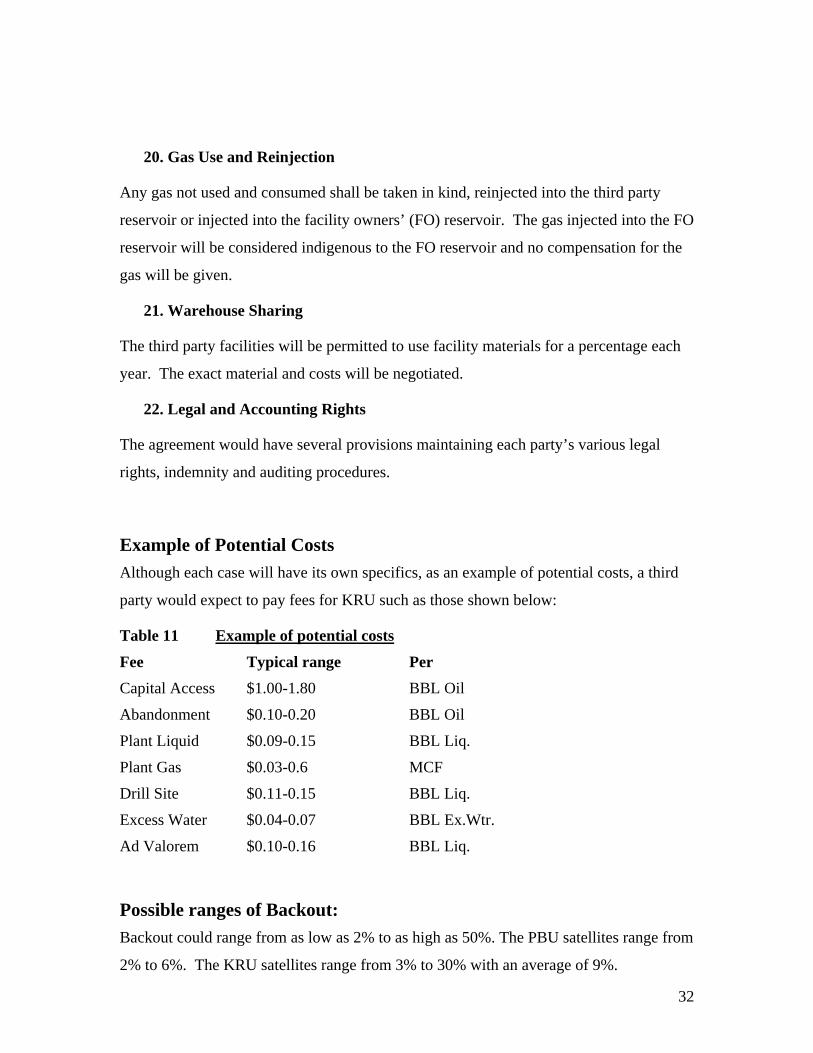
Example of Potential Costs Although each case will have its own specifics, as an example of potential costs, a third
party would expect to pay fees for KRU such as those shown below:
Table 11 Example of potential costs
Fee Typical range Per
Capital Access $1.00-1.80 BBL Oil
Abandonment $0.10-0.20 BBL Oil
Plant Liquid $0.09-0.15 BBL Liq.
Plant Gas $0.03-0.6 MCF
Drill Site $0.11-0.15 BBL Liq.
Excess Water $0.04-0.07 BBL Ex.Wtr.
Ad Valorem $0.10-0.16 BBL Liq.
Possible ranges of Backout: Backout could range from as low as 2% to as high as 50%. The PBU satellites range from
2% to 6%. The KRU satellites range from 3% to 30% with an average of 9%.

33
Backout Methodology Guidelines
The following procedures are guidelines for a hypothetical methodology for determining
the impact of backout fluids in facility sharing agreements. It is not intended to be all
inclusive and areas may be subject to negotiation for a specific agreement. Kuparuk
Ballot 255A is generally followed as this guideline. This methodology is detailed,
complex and heavily dependent on a detailed dynamic plant model. Presently, only the
KRU and PBU facilities have such a model in place. Other facilities would have to
develop such a model, make use of existing less sophisticated models or negotiate a
method for determination of backout volumes. See Backout Methodology Alternatives
Section.
The owners of the existing processing facilities shall be designated as “FO” and the
owners of the stream of fluids to be introduced into the facilities shall be designated as
“SO”. The term backout fluid means that volume of FO oil that will be deferred due to
the limitations of the facilities if the SO fluids are processed.
The concept of backout is real, and it represents actual deferred or lost production,
resulting in measurable loss of revenue to the facility owner. Backout only exists when
the facilities are constrained in some manner, causing the combined streams to be larger
than the capacity of the facilities. This is remedied by backing off the less efficient wells,
such as those with high GOR or WOR, in lieu of production from lower GOR or WOR
wells. In a simplified example, if the FO stream generates 100 mmscfd of gas and the
facilities can handle 120 mmscfd, while the SO stream generates 30 mmscfd, then the gas
handling is the limiting factor. For efficient operation of the facilities, the highest GOR
wells would be backed out, likely from the FO wells, thus reducing the overall production
for the FO but actually increasing the total sales oil production by adding the lower GOR
SO oil. This reduction in FO oil is called backout, and the FO must be compensated for
their lost or deferred production. This reduction volume is theoretically deferred until
production in the far future. The effect of this time delay in production is financial and
physical. The wells may not produce as efficiently when returned to service, the prices of
oil will be different, today’s value of the barrel will be discounted by the time delay of
production and the facilities may be uneconomical to operate thereby not recovering all
34
of the barrels. These situations are not easy to define, and an overall modification factor
can be negotiated to account for variance in these unknowns.
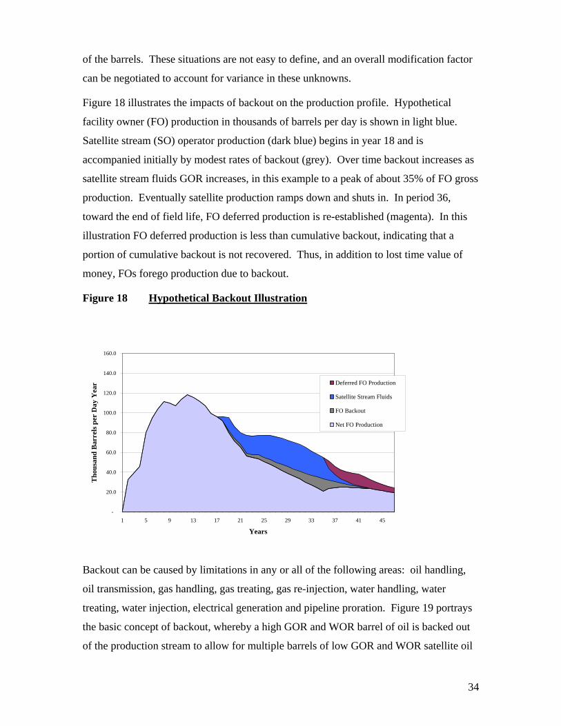
Figure 18 illustrates the impacts of backout on the production profile. Hypothetical
facility owner (FO) production in thousands of barrels per day is shown in light blue.
Satellite stream (SO) operator production (dark blue) begins in year 18 and is
accompanied initially by modest rates of backout (grey). Over time backout increases as
satellite stream fluids GOR increases, in this example to a peak of about 35% of FO gross
production. Eventually satellite production ramps down and shuts in. In period 36,
toward the end of field life, FO deferred production is re-established (magenta). In this
illustration FO deferred production is less than cumulative backout, indicating that a
portion of cumulative backout is not recovered. Thus, in addition to lost time value of
money, FOs forego production due to backout.
Figure 18 Hypothetical Backout Illustration
-
20.0
40.0
60.0
80.0
100.0
120.0
140.0
160.0
1 5 9 13 17 21 25 29 33 37 41 45
Years
Tho
usan
d B
arre
ls p
er D
ay Y
ear Deferred FO Production
Satellite Stream Fluids
FO Backout
Net FO Production
Backout can be caused by limitations in any or all of the following areas: oil handling,
oil transmission, gas handling, gas treating, gas re-injection, water handling, water
treating, water injection, electrical generation and pipeline proration. Figure 19 portrays
the basic concept of backout, whereby a high GOR and WOR barrel of oil is backed out
of the production stream to allow for multiple barrels of low GOR and WOR satellite oil

35
to be produced. The backed out barrel does have value, if produced, but it is relatively
small in relation to the satellite barrels.
Figure 19 Backout concept Water / Gas constrained facility
One Barrel current production high gas/ water cut oil
Water / Gas constrained facility
Nine Barrels potential satellite production low gas/ water cut oil
Application of General Backout Concepts:
• The backout calculations will be performed monthly.
• The basis of the calculations will be the average monthly allocated production and injection for that month (at the well level) as filed by the operator with the AOGCC.
• To the extent possible, the backout calculations will make use of logic that follows the optimization logic used in actual field operations.
• Adjustments will be made to account for any joint capital project participation by all parties.
• Changes in methodology will be made as appropriate to ensure the results reasonably reflect production adjustments.
• The operator shall be responsible for preparing the backout calculations.
36
Gas and Produced Water Backout:
This calculation is the first-order factor in calculating total backout, and it is based on
plant gas handling and produced water capacity limits, as well as the relative GOR and
WOR of the FO and SO streams. The operator uses a computer simulation program to
model the day to day processing operations at the facilities. The results are compared to
actual operations and calibration modifications are made to the model until the model
results match actual operations to within 5%. Then the program is run with its
optimization components to determine the basis for the calculations. All SO production
is “turned off” in the calculations and the production potential for FO is determined. If
there are more than one SO stream, a series of runs are made with one stream at a time
“turned off”. The results are used to determine the backout oil and the water oil ratio
(WOR) of the backed out oil.
Water Injection Backout:
The operator will have to have methodology for simulating the impacts of
reduced/increased water injection rates on the reservoir and production. This information
will determine the relationship of oil rate backed out as a result of reduced water
injection. Additional adjustments will be made to account for compressibility effects in
the reservoir and to minimize possible double counting of backed out production. The
WOR is used to determine the water injection backout for each SO stream.
Electrical Power Backout Calculations:
If electrical power generation capacity becomes a constraint to production, it is likely that
high water cut wells being lifted with electric submersible pumps would be shut in to free
up electrical capacity. It is also likely that these wells would be FO wells. To account
for this possibility, a backout amount will be calculated.
The operator will verify each month whether any electrical power related production
deferrals events occurred. If not, this calculation is not necessary. If an event occurred,
causing lower FO production, the electrical power-related backout volume and the
amount of power necessary to avoid this backout will be estimated. The total amount of
electrical power used directly by the SO will be tabulated and adjusted for any funded
electrical joint capital projects. The backout volume would be allocated according to the
37
SO usage. If the power necessary to avoid the backout is greater than the total SO usage,
then the impact of this calculation is to lower the total calculated backout.
Proration Adjustment Backout Calculations:
Production impacts caused by common carrier or marine capacity prorations are to be
shared by the FO and the SOs in percentages proportional to their gross share of pipeline
volume. If no proration events occurred for the month, then no calculation will be made.
If there are proration impacts, a table of the actual production and the estimated
production losses (actual proration) will be constructed for each stream. The difference
between the target proration and the actual proration is the theoretical adjustment. If the
number is negative, the stream will receive barrels and if positive, the stream will deliver
barrels. For example, if the FO production rate is 100,000 bopd, and the SO production
rate is 20,000 bopd, and a proration event calls for combined rate to be reduced to 60,000
bopd, then the FO rate would be prorated to 50,000 bopd, while the SO rate would be
prorated to 10,000 bopd. However, if operational considerations dictate that one or the
other stream does not reduce to the prorated value, the difference between that stream’s
actual production, and the prorated value triggers a backout calculation.
Modification Factor:
The parties will negotiate a further backout modification factor. Each stream’s net
backout shall be multiplied by the modification factor.
Backout Methodology Alternatives Several facilities may not have a detailed dynamic plant model to simulate their facility
operation. In that case, each facility will have to decide to either develop such a detailed
model or devise an alternative method using their existing models to calculate backout.
Each of these alternatives has associated costs that would be borne by all parties. Some
suggested possibilities are:
• Gather information of shut-in and curtailed wells based on GOR and
WOR and determine a theoretical production if these wells were not

38
curtailed. Prorate this number or an adjusted amount to the third parties
for barrel delivery after royalty and tax.
• Hire an independent processor to simulate the field once a year and agree
on a representative percentage to be applied throughout the year.
• Use a graph of the KRU or PBU satellite situation based on API, WOR
and GOR to estimate the backout percentage.
• As long as the pipelines are not at capacity, the State of Alaska could
consider implementing a program that takes the backout barrels from
royalty barrels or a portion thereof.
Commercial Considerations Commercial Framework The concept and practice of facility sharing is not new to the North Slope of Alaska.
Development of satellite fields within and adjacent to existing unit production has
required unit operators and owners to create agreements allowing for processing of
satellite production through existing or expanded facilities. Kuparuk River, Prudhoe Bay,
Lisburne, and Endicott production facilities provide for access to satellite production
through facility sharing and services agreements. The other North Slope units have not
developed such agreements.
The existing facility sharing agreements were not created with non-unit production in
mind, but they are de-facto templates for recent negotiations. The joinder agreement
(Appendix D) between Winstar and the Kuparuk River Unit is an example of the use of
Ballots 255, 255A, and 260 for the Kuparuk River Unit for third-party production.
Existing North Slope Facility Sharing agreements The North Slope has a number of existing agreements in place for access to processing
facilities. The fields that have not entered into infrastructure access agreements are:
Alpine, Badami, Milne Point, and Northstar. There are agreements for Kuparuk (Ballots
39
255, 255A and 260), Endicott, and Prudhoe Bay/Pt Mac/Lisburne. These are summarized
below:
Kuparuk
A series of ballots establishing facility access to the Kuparuk Participating Area (KPA)
are 255, 255A and 260. These agreements provide for the processing of a third party’s
satellite fluids (oil, water and gas), as well as access to injection water, electricity and
some common drillsite operations. The ballots offer ‘modified available capacity access’
and do not provide for ‘firm capacity access’ to the process facilities. This modified
available capacity is based on the principle that the best wells will be produced to
maximize facilities oil throughput, regardless of ownership. Therefore, assuming the
facilities are operating at full utilization, available capacity for any party is a function of
their well stream quality. Third parties pay for this facility access based on their
satellite’s actual utilization of the facilities.
Ballot 255 is the overriding ballot addressing the main principles of the sharing
agreement, Ballot 255A is a detailed description of the methodology for the backout
calculation, and Ballot 260 provides access to ancillary services. Ballots 255 and 255A
are included in the appendix (E and F).
Ballot 255 Summary:
• Satellites pay a capital access fee to compensate KPA owners for investments
made to put the process and related facilities in place. This fee is paid on a per-
barrel- of-oil basis.
• The Satellites also pay a fee (on a per barrel-of-oil basis) to cover future process
facility abandonment costs.
• Satellites pay fees to cover the satellite’s proportional share of fluid processing
and other common operation costs. These costs are determined yearly and based
on actual costs and production from the previous year.
40
• Satellites compensate the KPA owners for deferred production in the event KPA
production is ‘backed-out’ or restricted by satellite production. Backout is
calculated according to the methodology described in Ballot 255A.
• An oil quality adjustment is made to account for the differences in the
characteristics of KPA and satellite oil. The quality adjustment is determined
monthly and paid in barrels at Pump Station 1. If satellite crude is superior to
KPA crude, the satellite receives net barrels from the KPA. If satellite crude is
inferior to KPA crude, then the KPA receives net barrels from the satellite.
• Satellite owners must provide sufficient and timely information regarding the
Satellite plan of development and operation to enable the unit operator and KPA
owners to assess the demands and impacts the satellite may have on KPA
equipment, production and future operations.
• Satellite owners may install and operate their own wells and equipment.
Satellite owners are responsible for any and all efforts and direct costs associated
with satellite construction, permitting, maintenance, operation, taxes, royalty and
abandonment.
• The unit operator is responsible for operating all KPA process facilities,
pipelines and all wells on KPA drillsites as well as controlling the rate of
production into the facilities. Either the unit operator or a sub-operator will be
responsible for operating satellite equipment.
• Fluids must be compatible with KPA equipment. Satellite owners are
responsible for any costs to bring satellite fluids into compatibility.
• In the event of competing demands for process capacity, the unit operator will
strive to maximize total oil production through unit facilities. The best wells
will be produced, the worst wells will be shut-in or curtailed, regardless of
ownership. In the event that KPA production is deferred by this optimization of
total oil production, KPA owners will be kept whole and compensated through
the backout provisions.
41
• Satellite owners may propose KPA capacity expansions to meet their production
requirements. The KPA and various satellite owners will pay for such capacity
expansions in accordance to their relative benefit.
Ballot 260
Ballot 260 provides access to a wide range of services on an ad-hoc, as available,
basis. Some of the key services included in the document are:
• Mobile and non-mobile equipment
• Emergency fire response
• Spill response
• Waste management
• Camp services
• Materials
• Solid oily waste management
Endicott:
Endicott has two facility sharing agreements (FSA) in place for Eider and Sag Delta
North satellites and is a receiving entity under the IPA (Initial Participating Area) Ballot
Agreement 98-202: Authorizing Use of IPA Equipment and IPA Services. These
agreements provide for the development of the satellites using the Endicott facilities to
process fluids. The general terms of the FSAs are outlined below and a summary of the
IPA Ballot Agreement 98-202 is provided in the Prudhoe Bay Unit (PBU) and Pt.
Mac/Lisburne section.
Endicott FSAs Summary:
• Describes scope of satellite operations and equipment needs
• Provides access to Endicott facilities for operations, gathering and treating
of production

42
• Determines the satellite responsible for paying for any facility
modifications
• Establishes fees for various services provided
• Establishes equipment access, O&M, abandonment, excess power, and
make-up water fees
• Establishes fees for additional processing operations as applicable
• Sets production capacity priority based on competitive WOR/GOR if
capacity limited
• Provides backout calculation for production and value adjustment for
crude quality differences
• Provides fuel in-kind calculation
PBU and Pt. Mac/Lisburne:
There are three primary categories of facility sharing agreements relating to PBU
facilities and services. First, there are a number of agreements that relate to operations of
the Lisburne Production Center. Second, there are agreements related to processing PBU
satellite production in facilities originally developed to produce the main Prudhoe
reservoir (“IPA Facilities”) (Ballot 97-196). Third, there is an agreement authorizing
third-party sharing of certain equipment and services (“IPA Equipment and Services”)
(Ballot 98-202). The PBU Owners also have entered into agreements that address the use
of specific equipment.
A summary of these categories of agreements follows:
1. Lisburne Production Center Agreements
The Lisburne Production Center (LPC) was developed to process production from the
Lisburne Reservoir. In the early 1990s, agreements were developed to address what is
called the Greater Pt. McIntyre Area (“GPMA”). These agreements allow the Pt.
McIntyre, Niakuk, West Beach and North Prudhoe reservoirs (“Sharing PAs”) to be
processed through the LPC with Lisburne production, and for sharing between the IPA
43
Owners and the owners of the participating areas within the GPMA of certain support
facilities, electrical power, vertical support members, source water and other facilities and
services.
2. Facility Sharing Authorization Agreement (Ballot 97-196)
This agreement provides for the development of a Facility Sharing Agreement (FSA) for
each satellite field under which production fluids from that satellite could be processed
through the use of IPA Production Equipment. There are currently no FSAs with parties
external to the Prudhoe Bay Unit.
Owners of a satellite seeking access to IPA facilities must provide specific information
regarding the plans for development and operation of the satellite to enable the IPA
owners to evaluate demands and impacts that regular production from the satellite will
have on IPA production equipment and services, field development plans, and production
levels. This information includes:
(i) The scope and timing of Satellite development, including location of Satellite
well pads and facilities, projected number and timing of Satellite wells to be
drilled on each well pad, and identification of specific facilities for which access,
modification, use or tie-in is proposed;
(ii) Projections of satellite production to be delivered to IPA production
equipment, the quantities of “returned” gas (gas lift, fuel or injection) and satellite
produced water to be made available by the IPA owners to the satellite, all on a
year-to-year basis;
(iii) Description of electrical power, gas, make-up water or other IPA production
equipment and services for use by the satellite; and
(iv) Description of the stratigraphic horizon and areal extent for the portion of the
satellite reservoir proposed for development with compositional descriptions and
producing characteristics (e.g. temperatures and pressures) of the anticipated
satellite production.
Based on this information, the IPA owners may enter into an FSA that will specify
appropriate terms and conditions including:

44
i) The specific O&M fee, capital access fee, abandonment fee, backout, and
volume adjustment factor (VAF) as well as fees for use of IPA area equipment
and IPA services in support of subsurface satellite operations, additional
processing operations and satellite drilling and construction activities, and fees for
make-up water, additional electrical power or other items.
a) The O&M fee is to reimburse the IPA owners for the satellite’s
proportionate share of the IPA production equipment and services producing
costs for base processing operations.
b) The capital access fee is to reimburse the IPA owners for investment in
IPA production equipment.
c) The abandonment fee is to reimburse the IPA owners for a satellite’s
proportionate share of the estimated future abandonment costs for IPA
production equipment accessed by that satellite.
d) Backout is the estimated volume of IPA oil that cannot be produced
during a specified time period because of the processing of satellite
produced fluids through IPA Production Equipment. The Satellite is
responsible for keeping the IPA whole on deferred production by
reimbursing the IPA for backout with a volume of satellite production.
e) VAF is a volume adjustment to a satellite’s oil volume that reflects,
among other things, the differences in physical quality, compositional
differences and handling considerations of produced fluids from the IPA and
satellites.
(ii) Incorporation of specific terms and conditions which address any issues
raised by the information provided above including the commercial terms
required for any satellite modification, joint equipment or additional services
requested.
(iii) Scope and timing of development (including all satellite modification and
joint equipment requirements), range of rates for satellite production and reservoir
boundaries for which use of IPA production equipment and services will be
allowed.

45
3. Ballot Agreement Authorizing Use of IPA Equipment and IPA Services (Ballot
98-202)
This agreement authorizes the use of certain IPA area equipment and services (not
including oil and gas processing equipment) by other units/participating areas (receiving
entities), establishes terms of compensation for use of IPA area equipment and services,
and defines the allocation of liability between IPA owners and the receiving entities with
respect to the use of IPA equipment and services.
IPA equipment and services under Ballot 98-202 are intended to be for incidental use of
receiving entities. Use of IPA area equipment and services for other than incidental use
would be subject to a separate agreement negotiated on a case-by-case basis. (Incidental
use means use of equipment and services by a receiving entity that is in excess of the IPA
owners’ needs at the time of such use and that is insubstantial when compared to the IPA
owners’ use of such equipment or services.)
Equipment and Services include:
A) Mobile & non-mobile equipment
B) Airport shuttle bus services
C) Sewage disposal
D) Production lab
E) Wellhead services
F) Hot water plant
G) West Dock staging area
H) Drum disposal
I) Halon support services
J) Camp services
K) Projects & construction
L) Overhaul & rotating equipment
M) Scheurle trailer
N) Investment recovery
O) Flow measurement
P) Miscellaneous services
Q) Mukluk Pad
R) CTD work platform
S) Security checkpoint
4. Specific Equipment: Grind and Inject Plant Operating Agreement (IPA Ballot
97-201)
This agreement allows authorized parities to use the Grind and Inject Plant to dispose of
drilling waste for a fee.

46
Facility Sharing Analogs
The concept of Facility Sharing is a growing consideration in mature oil and gas basins
around the world. Aside from the examples mentioned above on the North Slope,
publicly available information pertaining to facility sharing agreements in other countries
exists. Understanding these agreements is useful when negotiating future agreements for
the North Slope. In general, the guiding principles from both the United Kingdom (U.K.)
Code of Practice and Alberta’s Jumping Pound formula are aligned with the existing
North Slope facility sharing agreements. Both Alberta and the Offshore U.K. have
mature oil and gas basins where the facility sharing concept has proven beneficial for
operators, third party producers, and the government. Both examples reviewed provide
for regulatory interdiction as needed to resolve disputes between negotiating parties,
although the UK Code of Practice has not had to rely on the government intervention
process to date. Emphasis on a cooperative approach to facility sharing has been
successful in negating the need for government interdiction. Both facility sharing
approaches outlined below are proven starting points for successful negotiations.
Existing agreements between unit partners on the North Slope present the obvious
starting point for new facility sharing agreements, and the highly cooperative approach
adopted in the United Kingdom sets a good example for expanding these existing
agreements to meet the needs of an expanding group of potential producers.
UK Offshore Infrastructure Code of Practice
The United Kingdom’s “Indicative Tariff” Code of Practice for offshore oil and gas
infrastructure is a cooperative industry document on the rules and procedures governing
third party access to these facilities. This document provides a framework for easy, fair
and non-discriminatory access to offshore oil and gas facilities. The process is supported
by the oil and gas industry. It is not mandated or enforced by a government agency,
however if a dispute over access does arise, there is a government body that has the legal
authority to settle the differences. The framework for third party facility access is a
combination of the Offshore Infrastructure Code of Practice for conducting commercial
negotiations and the legal backstop of appealing to the UK Secretary of State for Trade
and Industry to settle disputes over access. The real strengths of the system are the

47
adherence to a timeline for the negotiation and the support from all parties to have a
practical means of an early understanding of the availability and the approximate costs of
bringing and processing hydrocarbons in existing facilities.
The owners maintain an up-to-date database on their offshore infrastructure. When a
potential user requests this data, the owner has 10 days to respond with the requested data
as well as an indication of the probable tariff. If interested in proceeding, the user
formally contacts the owner and provides specifics as to the kind of hydrocarbon
composition and specifications, along with the development strategy. Within 30 days, or
a mutually agreed-upon timetable, the owner must reply to the prospective user with a
detailed technical response to the specifics of the requested facility use. If the request
from the user fits with the available access from the owners, the negotiations continue
with another 30 day clock. The parties may agree in the process of these final
negotiations to substantially change the standard terms they started with. The UK
Department of Trade and Industry (DTI) website is a valuable source of information, and
the Code of Practice can be found on their website: http://www.og.dti.gov.uk/regulation
The self-maintained database of the infrastructure owners is expected to include the
following data:
a. Technical description: Hydrocarbon entry specification, pressure
regimes/compressor curves at entry and exit, dehydration regime, process
diagrams and other operating conditions;
b. Operational capability including measures of past performance and reliability.
Planned changes affecting operational capability should be indicated;
c. Services that can be provided;
d. Indicative price of services;
e. Indicative forecast of available capacity normally for 5 years ahead, but for a
longer period for significant infrastructure; and
f. Pertinent general contract terms: lifting procedures, ownership, priorities, system
allocation principles, substitution terms, voting rights, etc.
48
Although this information does not constitute an offer capable of acceptance, it provides
to the user the indicative terms, which can be used as a yardstick as negotiations progress
toward settlement.
The prospective third-party user is expected to provide the following specific information
on the service requested:
a. Production profiles;
b. Compositions;
c. Start-up date;
d. Broad outline of development concept;
e. Hydrocarbon specification (such as H2S, CO2, gravity etc).
While this 1996 offshore infrastructure code of practice is a working process for facility
owners and potential third party users, it is still an evolving procedure. In 1998, the
Petroleum Act was instigated to provide an appeal process for the Secretary of State to
settle disputes over access. Further to this, in the spring of 2001, the UK Department of
Trade and Industry responded to allegations that access to infrastructure was still a
commercial barrier to oil and gas development with a study on the effectiveness of the
voluntary Infrastructure Code. The results of the study found that although it is not
necessary to replace or update the existing code, it is imperative to continue to check on
its effectiveness at least every three years. At this time, even though the code is not a
perfect system, it is still supported by the industry. Clearly this voluntary arrangement, in
combination with a legal backstop for the governing body to step in to provide a means to
settle disputes over access, is recognized as crucial for their continued offshore oil and
gas development. Currently, Work Groups formed by the DTI are preparing a proposal to
amend the Infrastructure Code of Practice with the key changes being:
• Allowing for the Secretary of State to become automatically involved in an
infrastructure access request if insufficient progress is being made after a
certain period (to be determined) and allowing the Secretary to set a tariff.
• Allowing for the provision of more information and transparency.
It is expected that this proposal will be published in May 2004.

49
There are no published examples of how the Code of Practice has worked, as these
negotiations for infrastructure terms are confidential. Per the Code, indicative tariff offers
are reported to the DTI, which are then published.
The Secretary of State, to date, has not been asked to formally intervene to set tariffs or
enforce access. Operators have preferred to work out agreements among themselves
rather than taking the risk of government intervention using methodology that is not
clearly defined. The Secretary’s office has participated informally in cases to move
negotiations along when companies complain.
Alberta’s Facility Sharing Agreement, the Jumping Pound Formula
Alberta Canada also has an industry-agreed-upon voluntary guideline for calculating oil
and gas processing tariff ranges. The access to infrastructure is agreed to be an open and
non-discriminatory access, in facilities where capacity is available. The Jumping Pound
methodology is based on an industry-derived formula. The formula was developed for a
case decided by Canada’s National Energy Board (NEB) for the processing tariff charged
at a gas processing plant at Jumping Pound in 1990.
The Alberta Jumping Pound Formula (JP 90/ 95) was developed jointly by a number
of industry organizations as a guideline for parties to use in negotiating fair and
reasonable fees on an everyday basis and to assist in dispute resolution. The Alberta
Energy and Utilities Board (EUB) supported the initiative but did not play a major role in
the development of the actual formula. The formula was developed to determine the
components which form any tariff rate for oil and gas processing at plants, e.g. rate of
return, rate base and range, operating costs, plant capacity, and special fee considerations.
The two documents describing the JP 90/95 formula are Gas Processing Fee, Jumping
Pound 1990 (Jp-90), January 1990, and Joint Industry Task Force Report On Processing
Fees JP-95, April 15, 1996, which have some general examples of cases.
The calculation for the fee establishing the calculated return on the capital investment for
the Jumping Pound Formula uses the original cost of the facilities as the Capital Base,
depreciated in a straight line over the life of the project (normally set at 20 years). A
return on capital is established as 15% before tax rate of return on the capital, and is

50
allocated among the owners of the facility as a capital allowance. Based on these costs,
the fee for the facility access is prorated per total throughput. Additionally, there is a
component of the formula that accounts for the sharing of the operating costs of the
facility. This component is generally also prorated on a production basis.
Although the formula is used voluntarily by the industry as a starting place for
negotiations on facility access, the key to Alberta’s facility sharing practice is the
regulatory board’s legal power to ensure a third party gains access to infrastructure.
Where disputes on processing fees cannot be resolved on a voluntary basis, there is
provision in the Alberta Oil and Gas Conservation Act (OGCA) for a party to apply to the
EUB to set the fees. When the EUB has receives an application and determines that it is
complete, a public hearing is scheduled to consider the application. The EUB has stated
that, if application is made to the EUB to set processing fees, it will use the Jumping
Pound Formula, unless there were compelling opposing reasons. The EUB gets very few
applications requesting the setting of processing or transportation fees (one or two a year,
typically), and has not yet set any such fees. All applications requesting fee-setting were
withdrawn while the applications were being processed. The EUB encourages parties to
continue negotiations or mediations in parallel with filing an application with the EUB.
Typically once a EUB hearing date is set these negotiations or mediations result in
resolution as the opposing party often does not want to be drawn into the regulatory arena
through the public hearing process. Although the EUB has not yet set any fees, it remains
prepared to do so.
The Alberta law dealing with third party access is set out in Part 9 of the OGCA.
Disputes on access may result from a number of issues - volumes, delivery points, fees,
drainage issues. The application requirements are set out in EUB Guide 65. (The OGCA
and Guide 65 are available on the EUB web site www.eub.gov.ab.ca.) If the EUB
approves an application, access is granted by means of an order which declares a party
to be a common carrier (access to a pipeline), common processor (access to a gas
processing plant), or common purchaser (access to market). An order can simply be a
declaration; for example, Company XYZ is a common processor of gas from the
Pipestone Viking F Pool. Additional direction can also be included to give effect to the
order; for example, the order can allocate production among producers in a pool (a usual
provision), specify the delivery point, or set out the fees. Usually an order does not deal

51
with all of these issues; the nature of the dispute that resulted in the application being
filed with the EUB determines which issues are addressed. When a party is declared to be
a common carrier, processor, or purchaser the OGCA requires it to treat parties without
discrimination within the limitations of the order (within a pool, typically).
The EUB has no data to know how widely JP90/95 is used as a benchmark, as the vast
majority of companies who want capacity in facilities they do not own (whether
processing plants or pipelines) are able to privately negotiate satisfactory voluntary
arrangements, and the matter does not come before the EUB. There is no requirement to
file contracts that result from these negotiations.
Independent Oil Companies’ Perspectives
PRA surveyed 15 independent oil companies currently interested in Alaska oil and gas
exploration to get their perspective on facility access and to identify their needs in
creating a template for negotiating access. Five of the companies contacted responded to
the survey, and others provided feedback through informal discussions, including open
discussions during a meeting of independent oil companies hosted by Alaska Governor
Frank Murkowski in Juneau in December of 2003.
The questions asked of these companies are listed in Appendix A.
The key areas identified as concerns and issues are:
• Backout calculations;
• Capital access fee methodology;
• Timing of negotiations;
• Insurance requirements;
• Operatorship;
• Trust and access to supporting information.
Summary of Independent Company Concerns:
Backout calculations

52
The term “backout fluid” describes the volume of oil currently going through the facility
that will be deferred due to the limitations of the facilities if third party fluids are
processed. Several concerns were cited regarding backout calculations, which range
from companies not wanting to pay backout costs at all, to a desire to see every detail
regarding the calculation of backout. The calculation is complicated, and is seen as a
“black-box”, with no supporting information available. The possible range of backout
costs is seen as very broad, and actual calculations are not accessible to third-party
producers.
Capital access fee methodology
This fee, associated with the capital cost of building and maintaining the existing
facilities is perceived again as a potential show-stopper to those seeking facility access.
The various methods available for calculating this fee can result in widely varying output,
and it is seen as a possible means for the facility owners to profit unfairly on third-party
production.
Timing of negotiations
Third-party producers have a need to run screening economics before investing in
exploration and development projects, and accessing the necessary cost information for
access to existing facilities currently takes too long. The first case in which third-party
access was negotiated took nearly three years to complete an agreement.
Insurance requirements An important issue to address, regardless of facility access needs, is insurance. Current
producers will require newcomers to secure insurance for any North Slope project they
pursue, whether self-operated or operated by a current producer. The current producers’
motivation is to avoid any and all liability for any catastrophic loss that might occur
during the operations – whether the loss involved a safety, environmental, or capital
issue. This concern is reasonable provided that the required amount of insurance should
is reasonable. Studies should be undertaken to determine risk levels and appropriate
insurance requirements. New producers should be informed and resolve the issue of
insurance early in the process to avoid unnecessarily exorbitant costs.
Operatorship issues and constraints

53
Another consideration prospective new producers on the North Slope face is whether to
operate their own production. The current North Slope producers have expressed a
willingness to entertain fee-based operatorship for new producers. Some of the
prospective new producers like this option, but others have expressed a strong desire to
operate their own production. These tend to be the producers with significant cold-
weather experience elsewhere in the world. They feel confident that they can utilize their
experience to reduce North Slope costs. Whether or not this is true is yet to be shown,
but the potential to introduce cost-saving ideas to the North Slope has promise not just for
the new producers but for the existing ones as well.
Trust and access to supporting documentation
Most of the parties are coming into the North Slope with no prior experience on the North
Slope, therefore the expense and operations are unknown. The lack of documentation
from the operators on the capital access fees and the “black box” calculations associated
with backout contribute to their suspicions and mistrust. Additionally, there is a concern
that the small independent companies will not receive the same access to and costs of
facility sharing that major third party companies receive.
Recommendations BP, ConocoPhillips and ExxonMobil historically have been major participants in the
development of oil resources on the North Slope of Alaska. All were leaders in building
the Trans Alaska Pipeline System. Today, they are three of the largest interest owners on
the North Slope, and BP and ConocoPhillips are the largest operators.
The environment for finding, developing and producing oil and gas is challenging and
complex, in Alaska and the world. The giant Prudhoe Bay and Kuparuk fields are in
decline. World energy markets continue to experience price volatility, competition for
capital and opportunities, and financial and technical challenges to discover, develop and
produce new fields.
The State of Alaska is committed to maintaining and enhancing competition, diversity
and balance in the exploration, development and production of North Slope resources,
sustaining and growing both oil and gas production, and ensuring that the State's natural
resources are developed in an environmentally and socially sensitive and responsible
54
manner. The operators recognize that a business opportunity exists for establishing a
formal agreement with fair terms for processing third party production volumes in
existing infrastructure.
In the State's view, expressed in the CHARTER FOR DEVELOPMENT of the Alaskan
North Slope, the Commissioner of Natural Resources possesses the statutory, regulatory
and contractual authority to require working interest owners to provide other producers
access to production and other facilities, on terms that are non-discriminatory, just and
reasonable. Under the Charter for Development, the Commissioner may require access
whenever necessary to
1. maximize the economic and physical recovery of the State's oil or gas resources,
2. maximize competition among parties seeking to explore and develop the
resources,
3. minimize the adverse effects of exploration, development, production and
transportation activity,
4. or otherwise to protect the best interests of the State.
Also, as stated in the CHARTER FOR DEVELOPMENT of the Alaskan North Slope, BP
and ConocoPhillips take no position on the State's view. BP and ConocoPhillips commit
that they will not unreasonably withhold their voting support as facilities owners for
allowing nearby satellites to have access to existing unit facilities on reasonable
commercial terms.
Recent history indicates that the owners and operators are willing to negotiate access.
PRA compliments the commitments stated above and makes the following
recommendations:
1. Nearly all of the existing facilities have the potential for developing or a
precedent for facility sharing agreements. The Independent producers
should expect to be able to negotiate an acceptable agreement. The
negotiations should be initiated by independent producers as early as
possible.

55
2. The largest obstacle to successful negotiations is a lack of trust.
Development and communication of a process for third-party facility
access which is fair and transparent will help to resolve this lack of trust,
and create opportunity for expanded resource development.
3. The Independents need to provide operators with a well thought out
development plan with as many crude characteristics as possible.
4. The most critical technical issue is the calculation of the backout volumes.
The operators need to communicate the backout methodology and be able
to respond to requests in a timely manner.
5. The Independents need to recognize backout is a valid concept,
representing real lost or deferred barrels to the facility owners.
6. Both parties need to be ready to compromise on the backout methodology
to simplify the calculations for fields without a detailed dynamic plant
model.
7. The State of Alaska has shown interest in investigating methods to defray
the backout impacts to the Independent producers, and this should be
continued.
8. Significant positive progress has been made through the compilation of
this report, and further investigation and communication should be
energetically pursued to assure continuation of this progress.

56
Appendix A
North Slope Facility Access Questionnaire
Where are you looking for access (i.e., southeast of Prudhoe Bay, northwest of Kuparuk)? Will operatorship be an issue? In other words, how important is it that you operate – or not operate – your own exploration or production? In addition to forecasts of capacity and cost at various facilities, what information do you need from operators? Are you familiar with ballots 255 and 260A? What are your impressions of these ballots as an acceptable platform for determining access to North Slope facilities? Based on your experiences in other basins, what advice would you give Alaskan operators and regulators in determining facilities access on the North Slope? If left to you, what would the North Slope facility access provisions look like? If you were Conoco-Phillips or BP, what would your access provisions look like? What experiences and insights might you offer to the State and the current North Slope operators to assist in cost management, both for developing new fields and for operating existing fields on the Slope? What have we not asked that you think is important to tell us?
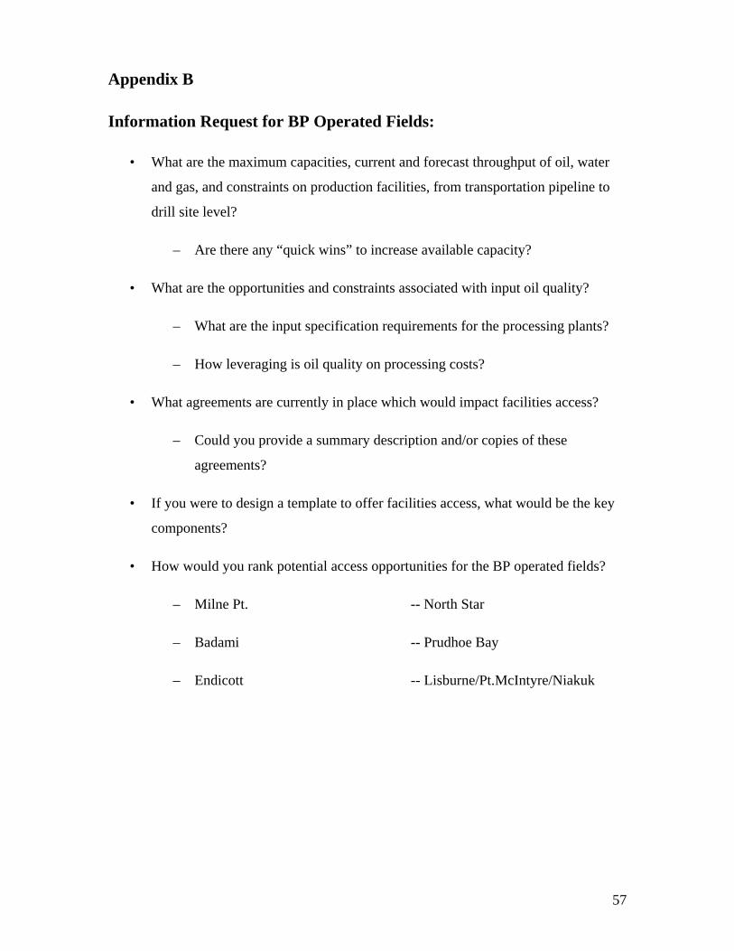
57
Appendix B
Information Request for BP Operated Fields:
• What are the maximum capacities, current and forecast throughput of oil, water
and gas, and constraints on production facilities, from transportation pipeline to
drill site level?
– Are there any “quick wins” to increase available capacity?
• What are the opportunities and constraints associated with input oil quality?
– What are the input specification requirements for the processing plants?
– How leveraging is oil quality on processing costs?
• What agreements are currently in place which would impact facilities access?
– Could you provide a summary description and/or copies of these
agreements?
• If you were to design a template to offer facilities access, what would be the key
components?
• How would you rank potential access opportunities for the BP operated fields?
– Milne Pt. -- North Star
– Badami -- Prudhoe Bay
– Endicott -- Lisburne/Pt.McIntyre/Niakuk

58
Information Request for CPAI Operated Fields
• What are the maximum capacities, current and forecast throughput of oil, water
and gas, and constraints on production facilities, from transportation pipeline to
drill site level?
– Are there any “quick wins” to increase available capacity?
• What are the opportunities and constraints associated with input oil quality?
– What are the input specification requirements for the processing plants?
– How leveraging is oil quality on processing and transportation costs?
• What agreements are currently in place which would impact facilities access?
– Could you provide a summary description and/or copies of these
agreements?
• If you were to design a template to offer facilities access, what would be the key
components?
• How would you rank potential access opportunities for the ConocoPhillips
operated fields?
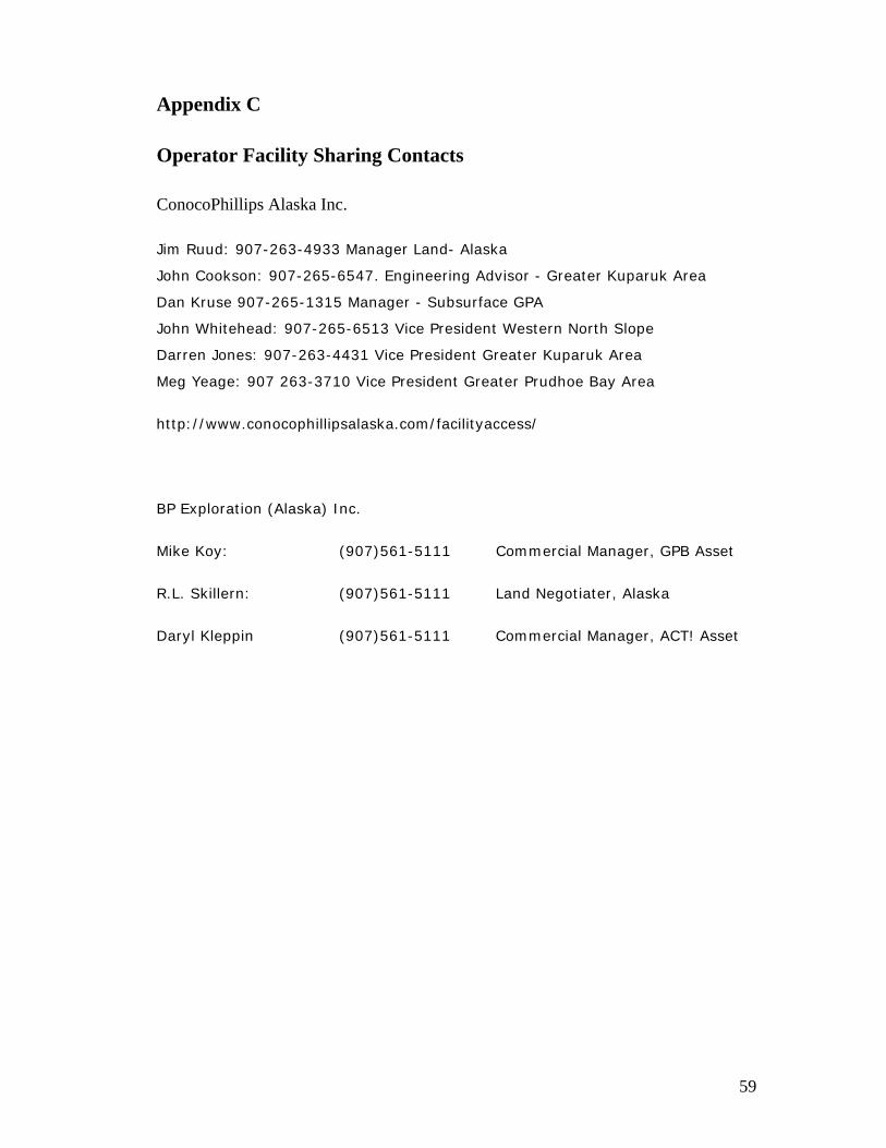
59
Appendix C
Operator Facility Sharing Contacts
ConocoPhillips Alaska Inc.
Jim Ruud: 907-263-4933 Manager Land- Alaska
John Cookson: 907-265-6547. Engineering Advisor - Greater Kuparuk Area
Dan Kruse 907-265-1315 Manager - Subsurface GPA
John Whitehead: 907-265-6513 Vice President Western North Slope
Darren Jones: 907-263-4431 Vice President Greater Kuparuk Area
Meg Yeage: 907 263-3710 Vice President Greater Prudhoe Bay Area
http://www.conocophillipsalaska.com/facilityaccess/
BP Exploration (Alaska) Inc.
Mike Koy: (907)561-5111 Commercial Manager, GPB Asset
R.L. Skillern: (907)561-5111 Land Negotiater, Alaska
Daryl Kleppin (907)561-5111 Commercial Manager, ACT! Asset

60
Appendix D
Joinder Agreement

61
Appendix E
KRU Ballot 255

62
Appendix F
KRU Ballot 255A


