
DDICInstructions for applicationDIRECT DRIVE PACKAGE
MISTRAL - B600 - TYPHON II
INSTRUCTIONS 1401-R00 e
Section 1401
Effective January 2020
Replaces November 2019
INSTALLATIONOPERATION
MAINTENANCESAFETY
STORAGE
Original instructions
Your distributor :
Z.I. La Plaine des Isles - F 89000 AUXERRE - FRANCE
Tel. : +33 (0)3.86.49.86.30 - Fax : +33 (0)3.86.49.87.17
[email protected] - www.mouvex.com
This Instruction only contains direct drive package information. It is imperative to have in complement the
compressor one and also all the others relatives to the accessories, also the parts list before installing the
equipment.
WARRANTY :DDIC packages (except the compressor : see compressor Instructions) are covered 24 months by warranty within the limits mentionedin our General Sales Conditions. In case of a use other than that mentioned in the Instructions manual, and without preliminary agreementof MOUVEX, warranty will be canceled.
2/18NT 1401-R00 01 20 Direct drive package DDIC e
MOUVEX TRUCK SCREW COMPRESSORSAFETY, STORAGE, INSTALLATION, OPERATION AND MAINTENANCE INSTRUCTIONS
MODELS : DDIC DIRECT DRIVE PACKAGE
MISTRAL - B600 - TYPHON II
REMARKS :
MOUVEX truck screw-type compressors MUST be installed in sys-
tems designed by qualified personnel. The installation MUST be in
compliance with local standards, national regulations and rules of
safety.
This package is designed to be used on paved roads. Unless,
it is necessary to move towards a package DDK to achieve a
strengthened and adapted to the situation set.
This manual is designed to permit installation and commis-
sioning of MOUVEX truck screw-type compressors and MUST
accompany the compressor.
Maintenance of MOUVEX screw-type compressors must ONLY be
carried out by qualified technicians. This maintenance must meet
local and national standards as well as all safety regulations.
Read this manual, including all instructions and warnings, in
full BEFORE any use of MOUVEX compressors.
Reading and the removal of the labels on the package apply to
approval.
ADDITIONAL DOCUMENTATION
The table below gives the list of instructions in addition
to this application instruction :
DDIC application Instructions Parts list
B600 20R/30R NT 1401-K00PL 1401-K01
PL 1401-R01
B600 13R/15L
B600 19R/22LNT 1401-K00
PL 1401-K01
PL 1401-Q01
PL 1401-R01
MISTRAL 20R/30R NT 1401-J00PL 1401-J01
PL 1401-R01
MISTRAL 13R/15L
MISTRAL 19R/22L NT 1401-J00
PL 1401-J01
PL 1401-Q01
PL 1401-R01
TYPHON II 20R/30R NT 1401-G00PL 1401-G01
PL 1401-R01
TYPHON II 13R/15L
TYPHON II 19R/22LNT 1401-G00
PL 1401-G01
PL 1401-Q01
PL 1401-R01
Torque limiter NT 1401-B00 PL 1401-Q01
Check and relief valve NT 1401-E00 PL 1401-Q01
Oil cooler NT 1401-AC00 PL 1401-Q01
1. OVERALL DIMENSIONS . . . . . . . . . . . . . . . . . . . . . . . . . .4
2. INSTALLATION . . . . . . . . . . . . . . . . . . . . . . . . . . . . . . . .102.1 Mounting location . . . . . . . . . . . . . . . . . . . . . . . . . . . .10
2.2 Mounting procedure . . . . . . . . . . . . . . . . . . . . . . . . . .10
2.3 At succion . . . . . . . . . . . . . . . . . . . . . . . . . . . . . . . . . .11
2.4 Check relief / Safety valve . . . . . . . . . . . . . . . . . . . . .12
2.5 Drive . . . . . . . . . . . . . . . . . . . . . . . . . . . . . . . . . . . . . .12
2.6 Electric circuit . . . . . . . . . . . . . . . . . . . . . . . . . . . . . . .14
2.7 Instrumentation . . . . . . . . . . . . . . . . . . . . . . . . . . . . . .14
2.8 Chair modification . . . . . . . . . . . . . . . . . . . . . . . . . . . .14
3. USE . . . . . . . . . . . . . . . . . . . . . . . . . . . . . . . . . . . . . . . . .14
4. MAINTENANCE . . . . . . . . . . . . . . . . . . . . . . . . . . . . . . . .154.1 Maintenance schedules . . . . . . . . . . . . . . . . . . . . . . .15
4.2 Air filter replacement procedure . . . . . . . . . . . . . . . . .15
4.3 Cartridge replacement procedure . . . . . . . . . . . . . . . .15
4.4 Drive train inspection . . . . . . . . . . . . . . . . . . . . . . . . .15
4.5 Check and relief valve inspection . . . . . . . . . . . . . . . .15
4.6 Warranty claims . . . . . . . . . . . . . . . . . . . . . . . . . . . . .15
5. TROUBLESHOOTING . . . . . . . . . . . . . . . . . . . . . . . . . . .16
6. STORAGE CONDITIONS . . . . . . . . . . . . . . . . . . . . . . . . .166.1 Compressor . . . . . . . . . . . . . . . . . . . . . . . . . . . . . . . .16
6.2 BSC oil . . . . . . . . . . . . . . . . . . . . . . . . . . . . . . . . . . . .16
7. SCRAPPING . . . . . . . . . . . . . . . . . . . . . . . . . . . . . . . . . .16
8. COMPRESSORS FORM INFORMATION . . . . . . . . . . . . .17
9. CERTIFICATE OF CONFORMITY . . . . . . . . . . . . . . . . . .18
TABLE OF CONTENTS Page Definition of safety symbols
This is a SAFETY ALERT SYMBOL.
When you see this symbol on the product, or in the manual,
look for one of the following signal words and be alert to the
potential for personal injury, death or major property damage.
Warns of hazards that WILL cause serious personal injury,
death or major property damage.
Warns of hazards that CAN cause serious personal injury,death or major property damage.
Warns of hazards that CAN cause personal injury or propertydamage.
NOTICEIndicates special instructions which are very important andmust be followed.
DANGER
WARNING
CAUTION
SAFETY CHECK LIST
1. Before operating the compressor, ensure the vessel to
which the compressor is connected is certified to withstand
the pressure and /or vacuum produced.
2. Verify adequately sized relief valves (if necessary, CE
approved) have been fitted to protect the vessel. Do not use
solvents or inflammable products for cleaning the pipelines and
the accessories.
3. Gas/air mixtures which are potentially volatile/explosive must
not be introduced or allowed to be introduced into the compres-
sor.
4. All pressure vessel and piping connected to the compres-
sor must be isolated and in a safe operating condition.
5. Operators should wear ear protection when operating truck
mounted compressors.
6. There are components within the compressor of sufficient
weight to cause injury if mishandled. Use proper lifting
devices as necessary.
7. Where necessary, this equipment should be grounded to
control static electricity.
8. The temperature of the air leaving the compressor is elevat-
ed above ambient due to air compression. Check that the
elevated temperatures do not adversely affect the product
and any material used in design of the system. Attach clear-
ly marked warning signs to warn of potentially hot surfaces
on the compressor, piping and accessories which will burn if
touched.
9. Mounting of the compressor must be correctly engineered
and the compressor must be properly secured. Refer to the
Compressor Mounting section of this manual.
NOTICE :MOUVEX PACKAGE COMPRESSORS ARE DESIGNED TO PRODUCE
COMPRESSED AIR. NOT TO PUMP GASES, LIQUIDS, POWDERS
OR CONDENSATES THOUGH THE COMPRESSOR. TO DO SO
WOULD VOID THE WARRANTY.
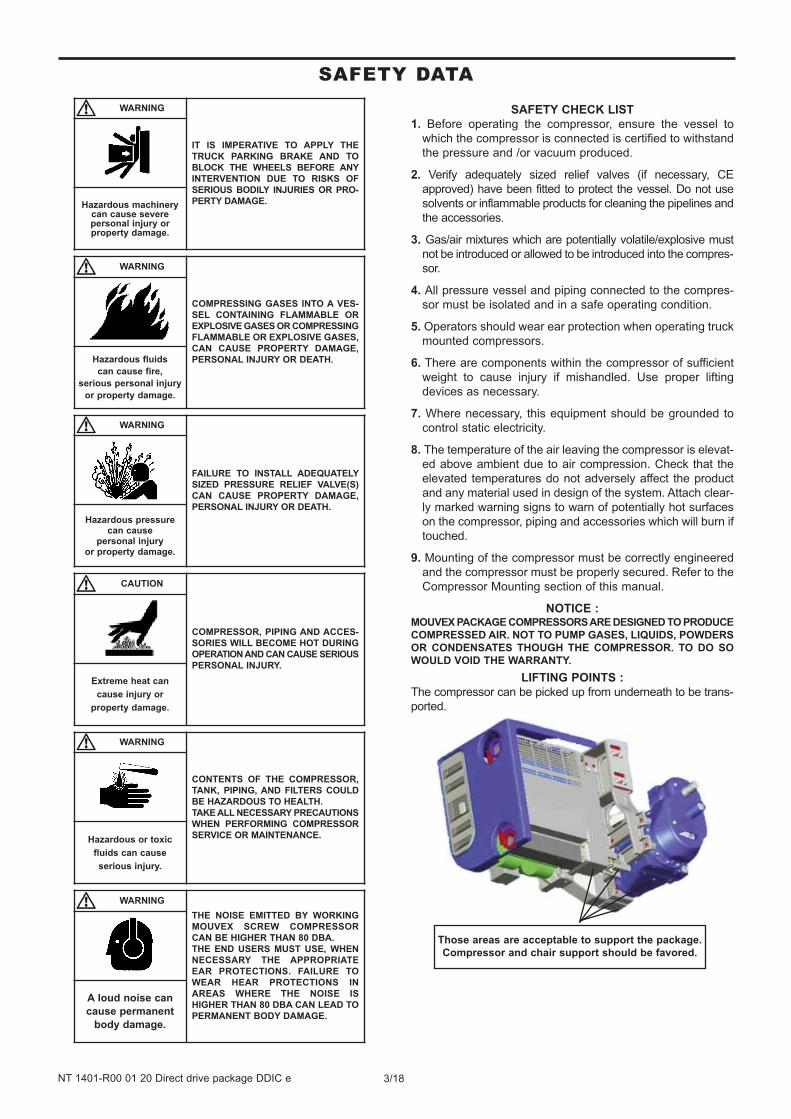
LIFTING POINTS :
The compressor can be picked up from underneath to be trans-
ported.
Those areas are acceptable to support the package.
Compressor and chair support should be favored.
WARNING
IT IS IMPERATIVE TO APPLY THE
TRUCK PARKING BRAKE AND TO
BLOCK THE WHEELS BEFORE ANY
INTERVENTION DUE TO RISKS OF
SERIOUS BODILY INJURIES OR PRO-
PERTY DAMAGE.Hazardous machinery can cause severepersonal injury or property damage.
WARNING
COMPRESSING GASES INTO A VES-
SEL CONTAINING FLAMMABLE OR
EXPLOSIVE GASES OR COMPRESSING
FLAMMABLE OR EXPLOSIVE GASES,
CAN CAUSE PROPERTY DAMAGE,
PERSONAL INJURY OR DEATH.Hazardous fluids
can cause fire,
serious personal injury
or property damage.
WARNING
FAILURE TO INSTALL ADEQUATELY
SIZED PRESSURE RELIEF VALVE(S)
CAN CAUSE PROPERTY DAMAGE,
PERSONAL INJURY OR DEATH.
Hazardous pressure can cause
personal injury or property damage.
CAUTION
COMPRESSOR, PIPING AND ACCES-
SORIES WILL BECOME HOT DURING
OPERATION AND CAN CAUSE SERIOUS
PERSONAL INJURY.
Extreme heat can
cause injury or
property damage.
WARNING
CONTENTS OF THE COMPRESSOR,
TANK, PIPING, AND FILTERS COULD
BE HAZARDOUS TO HEALTH.
TAKE ALL NECESSARY PRECAUTIONS
WHEN PERFORMING COMPRESSOR
SERVICE OR MAINTENANCE.Hazardous or toxic
fluids can cause
serious injury.
WARNING
THE NOISE EMITTED BY WORKING
MOUVEX SCREW COMPRESSOR
CAN BE HIGHER THAN 80 DBA.
THE END USERS MUST USE, WHEN
NECESSARY THE APPROPRIATE
EAR PROTECTIONS. FAILURE TO
WEAR HEAR PROTECTIONS IN
AREAS WHERE THE NOISE IS
HIGHER THAN 80 DBA CAN LEAD TO
PERMANENT BODY DAMAGE.
A loud noise can
cause permanent
body damage.
3/18NT 1401-R00 01 20 Direct drive package DDIC e
SAFETY DATA
4/18NT 1401-R00 01 20 Direct drive package DDIC e
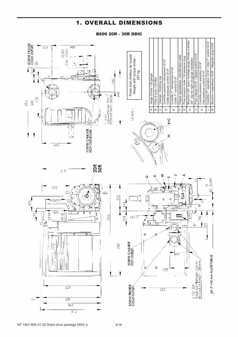
B600 20R - 30R DDIC
1. OVERALL DIMENSIONS
Poid
s a
vec lim
iteur
de c
ouple
Weig
ht
with t
orq
ue lim
iter
:
257 k
g
AJa
ug
e d
’hu
ile /
Oil
ga
ug
e
BF
iltre
à h
uile
/ O
il filte
r
CV
ida
ng
e /
Dra
inin
g c
ap
DC
on
trô
le p
ressio
n r
efo
ule
me
nt
G1
/4”
Ou
tle
t p
ressu
re c
on
tro
l G
1/4
”
EC
on
trô
le T
° re
fou
lem
en
t G
1/4
”
Ou
tle
t T
° co
ntr
ol G
1/4
”
FP
laq
ue
sig
na
létiq
ue
/ I
de
ntifica
tio
n p
late
GP
rise
pre
ssio
n h
uile
/ O
il p
ressu
re p
lug
HB
ou
ch
on
3/4
” (p
ou
r m
on
tag
e ja
ug
e d
’hu
ile à
dro
ite
)
3/4
” ca
p f
or
rig
ht
oil
ga
ug
e in
sta
llatio
n
JP
rise
vite
sse
G1
/4”
/ S
pe
ed
co
ntr
ol G
1/4
”
KC
on
trô
le p
ressio
n a
sp
ira
tio
n G
1/4
”
Inle
t p
ressu
re c
on
tro
l G
1/4
”
LC
on
trô
le T
° a
sp
ira
tio
n G
1/4
” /
Inle
t T
° co
ntr
ol G
1/4
”
MB
ou
ch
on
ma
gn
étiq
ue
G3
/8”
/ M
ag
ne
tic p
lug
G3
/8”
5/18NT 1401-R00 01 20 Direct drive package DDIC e
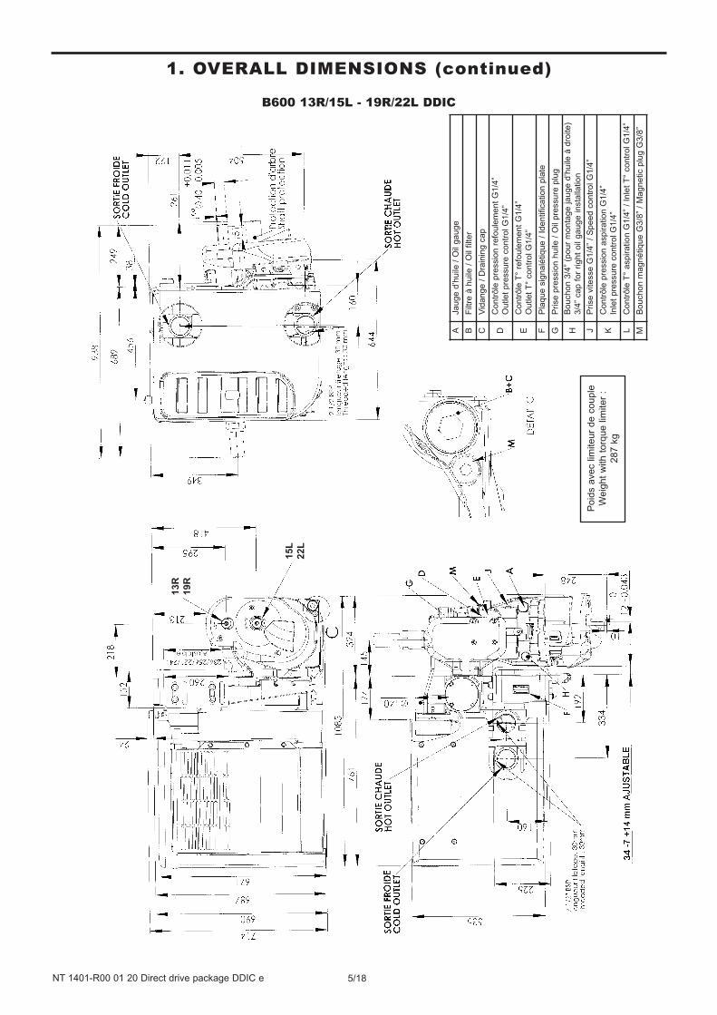
B600 13R/15L - 19R/22L DDIC
1. OVERALL DIMENSIONS (continued)
Poid
s a
vec lim
iteur
de c
ouple
Weig
ht
with t
orq
ue lim
iter
:
287 k
g
AJa
ug
e d
’hu
ile /
Oil
ga
ug
e
BF
iltre
à h
uile
/ O
il filte
r
CV
ida
ng
e /
Dra
inin
g c
ap
DC
on
trô
le p
ressio
n r
efo
ule
me
nt
G1
/4”
Ou
tle
t p
ressu
re c
on
tro
l G
1/4
”
EC
on
trô
le T
° re
fou
lem
en
t G
1/4
”
Ou
tle
t T
° co
ntr
ol G
1/4
”
FP
laq
ue
sig
na
létiq
ue
/ I
de
ntifica
tio
n p
late
GP
rise
pre
ssio
n h
uile
/ O
il p
ressu
re p
lug
HB
ou
ch
on
3/4
” (p
ou
r m
on
tag
e ja
ug
e d
’hu
ile à
dro
ite
)
3/4
” ca
p f
or
rig
ht
oil
ga
ug
e in
sta
llatio
n
JP
rise
vite
sse
G1
/4”
/ S
pe
ed
co
ntr
ol G
1/4
”
KC
on
trô
le p
ressio
n a
sp
ira
tio
n G
1/4
”
Inle
t p
ressu
re c
on
tro
l G
1/4
”
LC
on
trô
le T
° a
sp
ira
tio
n G
1/4
” /
Inle
t T
° co
ntr
ol G
1/4
”
MB
ou
ch
on
ma
gn
étiq
ue
G3
/8”
/ M
ag
ne
tic p
lug
G3
/8”
13R
19R
15L
22L
6/18NT 1401-R00 01 20 Direct drive package DDIC e
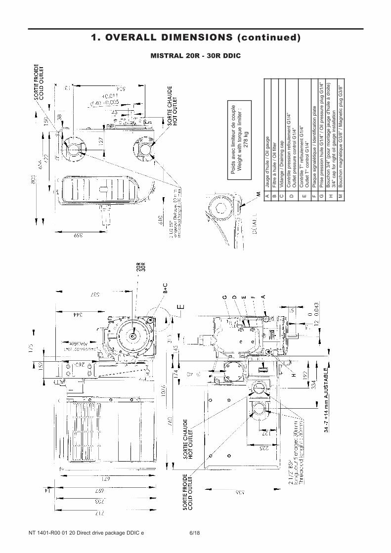
MISTRAL 20R - 30R DDIC
1. OVERALL DIMENSIONS (continued)
Poid
s a
vec lim
iteur
de c
ouple
Weig
ht
with t
orq
ue lim
iter
:
278 k
g
AJa
ug
e d
’hu
ile /
Oil
ga
ug
e
BF
iltre
à h
uile
/ O
il filte
r
CV
ida
ng
e /
Dra
inin
g c
ap
DC
on
trô
le p
ressio
n r
efo
ule
me
nt
G1
/4”
Ou
tle
t p
ressu
re c
on
tro
l G
1/4
”
EC
on
trô
le T
° re
fou
lem
en
t G
1/4
”
Ou
tle
t T
° co
ntr
ol G
1/4
”
FP
laq
ue
sig
na
létiq
ue
/ I
de
ntifica
tio
n p
late
GP
rise
pre
ssio
n h
uile
G1
/4”
/ O
il p
ressu
re p
lug
G1
/4”
HB
ou
ch
on
3/4
” (p
ou
r m
on
tag
e ja
ug
e d
’hu
ile à
dro
ite
)
3/4
” ca
p f
or
rig
ht
oil
ga
ug
e in
sta
llatio
n
MB
ou
ch
on
ma
gn
étiq
ue
G3
/8”
/ M
ag
ne
tic p
lug
G3
/8”
7/18NT 1401-R00 01 20 Direct drive package DDIC e
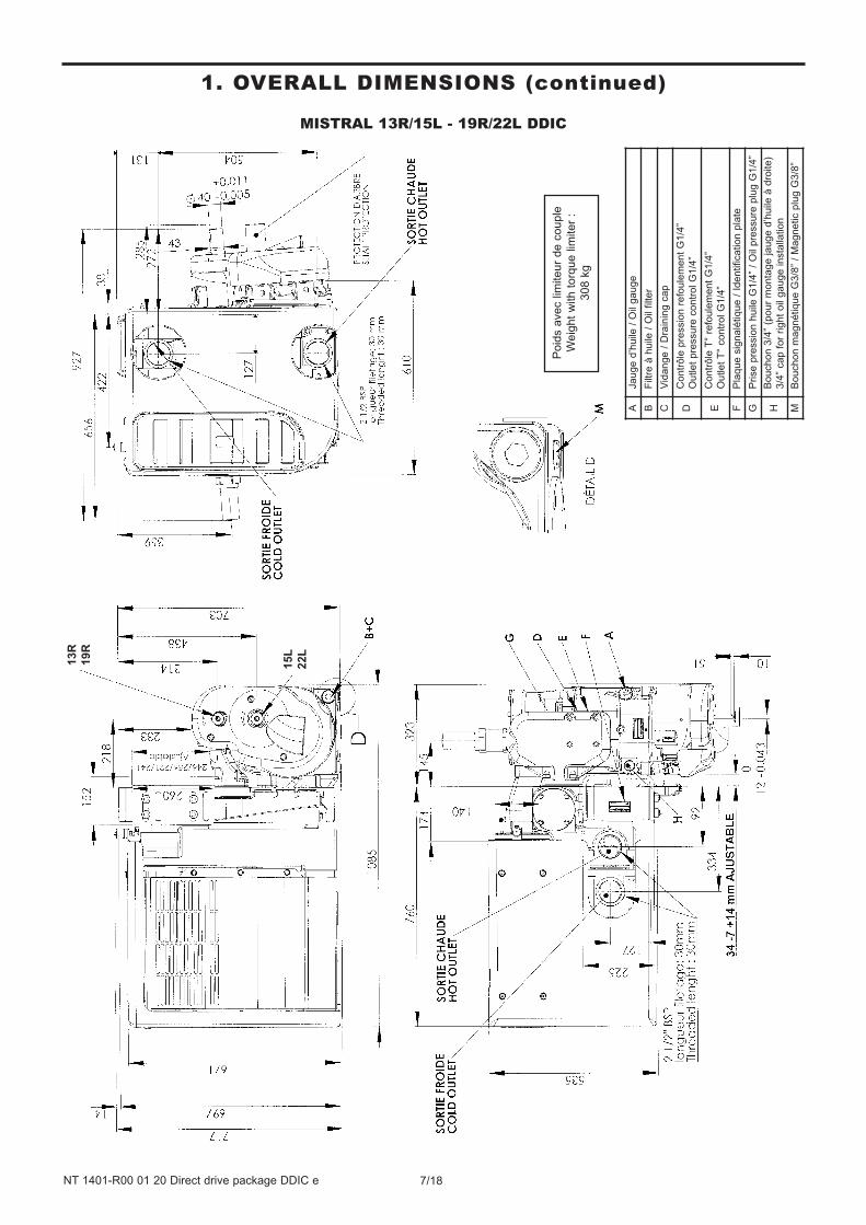
MISTRAL 13R/15L - 19R/22L DDIC
1. OVERALL DIMENSIONS (continued)
Poid
s a
vec lim
iteur
de c
ouple
Weig
ht
with t
orq
ue lim
iter
:
308 k
g
13R
19R
15L
22L
AJa
ug
e d
’hu
ile /
Oil
ga
ug
e
BF
iltre
à h
uile
/ O
il filte
r
CV
ida
ng
e /
Dra
inin
g c
ap
DC
on
trô
le p
ressio
n r
efo
ule
me
nt
G1
/4”
Ou
tle
t p
ressu
re c
on
tro
l G
1/4
”
EC
on
trô
le T
° re
fou
lem
en
t G
1/4
”
Ou
tle
t T
° co
ntr
ol G
1/4
”
FP
laq
ue
sig
na
létiq
ue
/ I
de
ntifica
tio
n p
late
GP
rise
pre
ssio
n h
uile
G1
/4”
/ O
il p
ressu
re p
lug
G1
/4”
HB
ou
ch
on
3/4
” (p
ou
r m
on
tag
e ja
ug
e d
’hu
ile à
dro
ite
)
3/4
” ca
p f
or
rig
ht
oil
ga
ug
e in
sta
llatio
n
MB
ou
ch
on
ma
gn
étiq
ue
G3
/8”
/ M
ag
ne
tic p
lug
G3
/8”
8/18NT 1401-R00 01 20 Direct drive package DDIC e
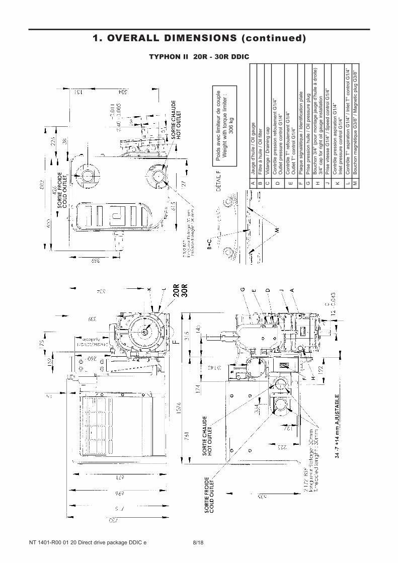
TYPHON II 20R - 30R DDIC
1. OVERALL DIMENSIONS (continued)
Poid
s a
vec lim
iteur
de c
ouple
Weig
ht
with t
orq
ue lim
iter
:
306 k
g
AJa
ug
e d
’hu
ile /
Oil
ga
ug
e
BF
iltre
à h
uile
/ O
il filte
r
CV
ida
ng
e /
Dra
inin
g c
ap
DC
on
trô
le p
ressio
n r
efo
ule
me
nt
G1
/4”
Ou
tle
t p
ressu
re c
on
tro
l G
1/4
”
EC
on
trô
le T
° re
fou
lem
en
t G
1/4
”
Ou
tle
t T
° co
ntr
ol G
1/4
”
FP
laq
ue
sig
na
létiq
ue
/ I
de
ntifica
tio
n p
late
GP
rise
pre
ssio
n h
uile
/ O
il p
ressu
re p
lug
HB
ou
ch
on
3/4
” (p
ou
r m
on
tag
e ja
ug
e d
’hu
ile à
dro
ite
)
3/4
” ca
p f
or
rig
ht
oil
ga
ug
e in
sta
llatio
n
JP
rise
vite
sse
G1
/4”
/ S
pe
ed
co
ntr
ol G
1/4
”
KC
on
trô
le p
ressio
n a
sp
ira
tio
n G
1/4
”
Inle
t p
ressu
re c
on
tro
l G
1/4
”
LC
on
trô
le T
° a
sp
ira
tio
n G
1/4
” /
Inle
t T
° co
ntr
ol G
1/4
”
MB
ou
ch
on
ma
gn
étiq
ue
G3
/8”
/ M
ag
ne
tic p
lug
G3
/8”
9/18NT 1401-R00 01 20 Direct drive package DDIC e
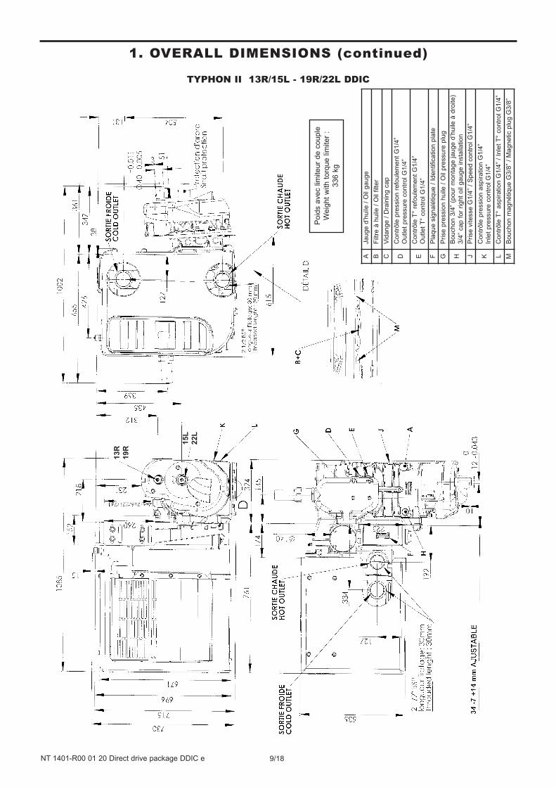
TYPHON II 13R/15L - 19R/22L DDIC
1. OVERALL DIMENSIONS (continued)
Poid
s a
vec lim
iteur
de c
ouple
Weig
ht
with t
orq
ue lim
iter
:
336 k
g
13R
19R
15L
22L
AJa
ug
e d
’hu
ile /
Oil
ga
ug
e
BF
iltre
à h
uile
/ O
il filte
r
CV
ida
ng
e /
Dra
inin
g c
ap
DC
on
trô
le p
ressio
n r
efo
ule
me
nt
G1
/4”
Ou
tle
t p
ressu
re c
on
tro
l G
1/4
”
EC
on
trô
le T
° re
fou
lem
en
t G
1/4
”
Ou
tle
t T
° co
ntr
ol G
1/4
”
FP
laq
ue
sig
na
létiq
ue
/ I
de
ntifica
tio
n p
late
GP
rise
pre
ssio
n h
uile
/ O
il p
ressu
re p
lug
HB
ou
ch
on
3/4
” (p
ou
r m
on
tag
e ja
ug
e d
’hu
ile à
dro
ite
)
3/4
” ca
p f
or
rig
ht
oil
ga
ug
e in
sta
llatio
n
JP
rise
vite
sse
G1
/4”
/ S
pe
ed
co
ntr
ol G
1/4
”
KC
on
trô
le p
ressio
n a
sp
ira
tio
n G
1/4
”
Inle
t p
ressu
re c
on
tro
l G
1/4
”
LC
on
trô
le T
° a
sp
ira
tio
n G
1/4
” /
Inle
t T
° co
ntr
ol G
1/4
”
MB
ou
ch
on
ma
gn
étiq
ue
G3
/8”
/ M
ag
ne
tic p
lug
G3
/8”
The screws used to :• hold the compressor in place
• mount the filter flange
• mount the discharge flange
must be at least quality 12-9.
During the assembly, watch that no foreign body penetrates
into the compressor. The piping of inhalation and expulsion
must be perfectly clean. Any foreign body risks to damage
seriously the compressor.
The presence of foreign bodies in the compressor inlet
channel is susceptible of leading to serious property
damage or serious injuries.
2.1 Mounting locationThe compressor must be installed in a location where it is
easily accessible. In particular, make sure that the oil
filling plug, oil magnetic plugs and the filter are accessible.
The clogging indicator must remain visible to the operator.
Choose a location where the compressor is relatively
protected from gravel projections and road spray as well
as exhaust fumes and engine heat.
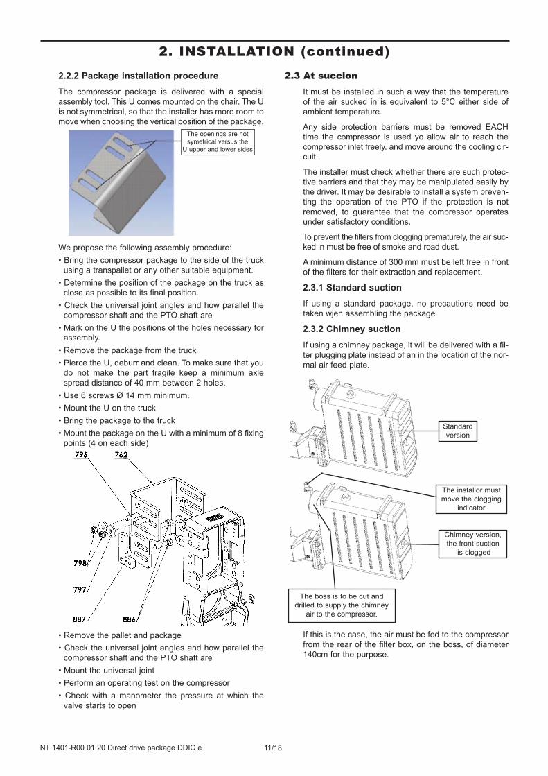
The compressor is mounted on the chair at an angle of
4°. If the chair is mounted vertically, it can be used to
adapt to most movements, in other words those which
have a gradient of between 3 and 5° inclusive.
To prevent potential interferences between the package
and the truck accessories (mudflap, tank…) a minimum
distance of 5 cm between the package and these acces-
sories must be respected.
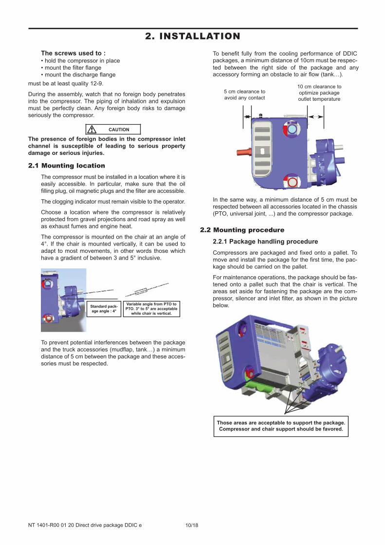
To benefit fully from the cooling performance of DDIC packages, a minimum distance of 10cm must be respec-
ted between the right side of the package and any accessory forming an obstacle to air flow (tank…).
In the same way, a minimum distance of 5 cm must be
respected between all accessories located in the chassis
(PTO, universal joint, ...) and the compressor package.
2.2 Mounting procedure
2.2.1 Package handling procedure
Compressors are packaged and fixed onto a pallet. To
move and install the package for the first time, the pac-
kage should be carried on the pallet.
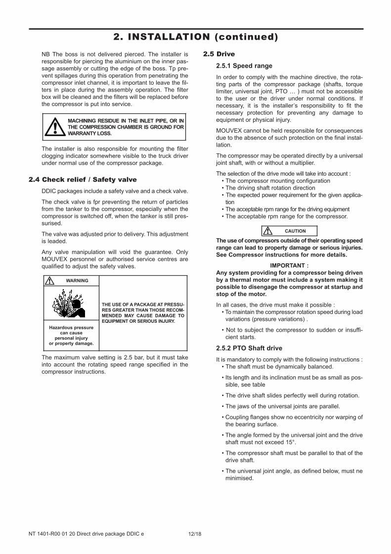
For maintenance operations, the package should be fas-
tened onto a pallet such that the chair is vertical. The
areas set aside for fastening the package are the com-
pressor, silencer and inlet filter, as shown in the picture
below.Standard pack-
age angle : 4°
Variable angle from PTO to
PTO. 3° to 5° are acceptable
while chair is vertical.
Those areas are acceptable to support the package.
Compressor and chair support should be favored.
5 cm clearance to
avoid any contact
10 cm clearance to
optimize package
outlet temperature
CAUTION
10/18NT 1401-R00 01 20 Direct drive package DDIC e
2. INSTALLATION
11/18NT 1401-R00 01 20 Direct drive package DDIC e
2. INSTALLATION (continued)
2.2.2 Package installation procedure
The compressor package is delivered with a special
assembly tool. This U comes mounted on the chair. The U
is not symmetrical, so that the installer has more room to
move when choosing the vertical position of the package.
We propose the following assembly procedure:
• Bring the compressor package to the side of the truck
using a transpallet or any other suitable equipment.
• Determine the position of the package on the truck as
close as possible to its final position.
• Check the universal joint angles and how parallel the
compressor shaft and the PTO shaft are
• Mark on the U the positions of the holes necessary for
assembly.
• Remove the package from the truck
• Pierce the U, deburr and clean. To make sure that you
do not make the part fragile keep a minimum axle
spread distance of 40 mm between 2 holes.
• Use 6 screws Ø 14 mm minimum.
• Mount the U on the truck
• Bring the package to the truck
• Mount the package on the U with a minimum of 8 fixing
points (4 on each side)
• Remove the pallet and package
• Check the universal joint angles and how parallel the
compressor shaft and the PTO shaft are
• Mount the universal joint
• Perform an operating test on the compressor
• Check with a manometer the pressure at which the
valve starts to open
2.3 At succionIt must be installed in such a way that the temperature
of the air sucked in is equivalent to 5°C either side of
ambient temperature.
Any side protection barriers must be removed EACH
time the compressor is used yo allow air to reach the
compressor inlet freely, and move around the cooling cir-
cuit.
The installer must check whether there are such protec-
tive barriers and that they may be manipulated easily by
the driver. It may be desirable to install a system preven-
ting the operation of the PTO if the protection is not
removed, to guarantee that the compressor operates
under satisfactory conditions.
To prevent the filters from clogging prematurely, the air suc-
ked in must be free of smoke and road dust.
A minimum distance of 300 mm must be left free in front
of the filters for their extraction and replacement.
2.3.1 Standard suction
If using a standard package, no precautions need be
taken wjen assembling the package.
2.3.2 Chimney suction
If using a chimney package, it will be delivered with a fil-
ter plugging plate instead of an in the location of the nor-
mal air feed plate.
If this is the case, the air must be fed to the compressor
from the rear of the filter box, on the boss, of diameter
140cm for the purpose.
Standard
version
The installor must
move the clogging
indicator
Chimney version,
the front suction
is clogged
The boss is to be cut and
drilled to supply the chimney
air to the compressor.
The openings are not
symetrical versus the
U upper and lower sides
NB The boss is not delivered pierced. The installer is
responsible for piercing the aluminium on the inner pas-
sage assembly or cutting the edge of the boss. Tp pre-
vent spillages during this operation from penetrating the
compressor inlet channel, it is important to leave the fil-
ters in place during the assembly operation. The filter
box will be cleaned and the filters will be replaced before
the compressor is put into service.
The installer is also responsible for mounting the filter
clogging indicator somewhere visible to the truck driver
under normal use of the compressor package.
2.4 Check relief / Safety valveDDIC packages include a safety valve and a check valve.
The check valve is fpr preventing the return of particles
from the tanker to the compressor, especially when the
compressor is switched off, when the tanker is still pres-
surised.
The valve was adjusted prior to delivery. This adjustment
is leaded.
Any valve manipulation will void the guarantee. Only
MOUVEX personnel or authorised service centres are
qualified to adjust the safety valves.
The maximum valve setting is 2.5 bar, but it must take
into account the rotating speed range specified in the
compressor instructions.
2.5 Drive
2.5.1 Speed range
In order to comply with the machine directive, the rota-
ting parts of the compressor package (shafts, torque
limiter, universal joint, PTO … ) must not be accessible
to the user or the driver under normal conditions. If
necessary, it is the installer’s responsibility to fit the
necessary protection for preventing any damage to
equipment or physical injury.
MOUVEX cannot be held responsible for consequences
due to the absence of such protection on the final instal-
lation.
The compressor may be operated directly by a universal
joint shaft, with or without a multiplier.
The selection of the drive mode will take into account :
• The compressor mounting configuration
• The driving shaft rotation direction
• The expected power requirement for the given applica-
tion
• The acceptable rpm range for the driving equipment
• The acceptable rpm range for the compressor.
The use of compressors outside of their operating speed
range can lead to property damage or serious injuries.
See Compressor instructions for more details.
IMPORTANT :
Any system providing for a compressor being driven
by a thermal motor must include a system making it
possible to disengage the compressor at startup and
stop of the motor.
In all cases, the drive must make it possible :
• To maintain the compressor rotation speed during load
variations (pressure variations) .
• Not to subject the compressor to sudden or insuffi-
cient starts.
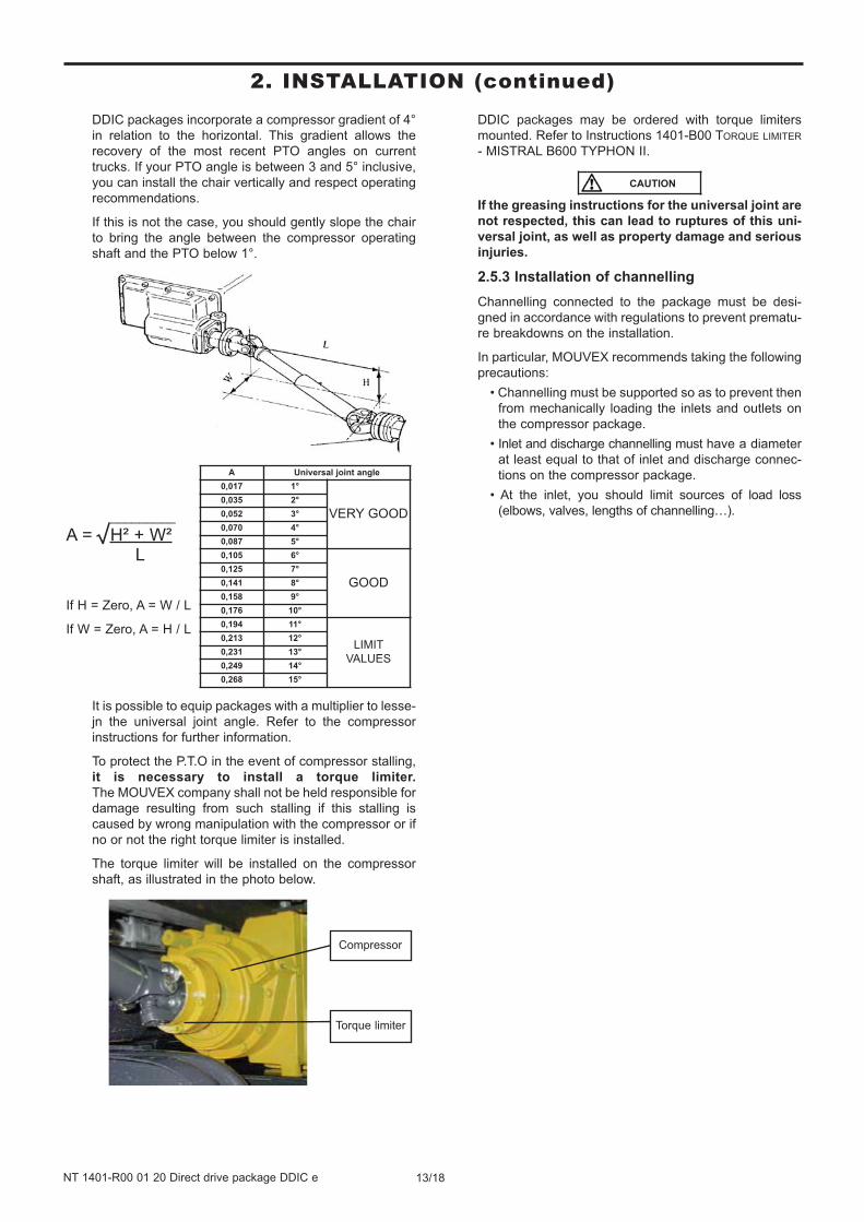
2.5.2 PTO Shaft drive
It is mandatory to comply with the following instructions :
• The shaft must be dynamically balanced.
• Its length and its inclination must be as small as pos-
sible, see table
• The drive shaft slides perfectly well during rotation.
• The jaws of the universal joints are parallel.
• Coupling flanges show no eccentricity nor warping of
the bearing surface.
• The angle formed by the universal joint and the drive
shaft must not exceed 15°.
• The compressor shaft must be parallel to that of the
drive shaft.
• The universal joint angle, as defined below, must ne
minimised.
MACHINING RESIDUE IN THE INLET PIPE, OR IN
THE COMPRESSION CHAMBER IS GROUND FOR
WARRANTY LOSS.
CAUTION
WARNING
THE USE OF A PACKAGE AT PRESSU-
RES GREATER THAN THOSE RECOM-
MENDED MAY CAUSE DAMAGE TO
EQUIPMENT OR SERIOUS INJURY.
Hazardous pressure can cause
personal injury or property damage.
12/18NT 1401-R00 01 20 Direct drive package DDIC e
2. INSTALLATION (continued)
DDIC packages incorporate a compressor gradient of 4°
in relation to the horizontal. This gradient allows the
recovery of the most recent PTO angles on current
trucks. If your PTO angle is between 3 and 5° inclusive,
you can install the chair vertically and respect operating
recommendations.
If this is not the case, you should gently slope the chair
to bring the angle between the compressor operating
shaft and the PTO below 1°.
It is possible to equip packages with a multiplier to lesse-
jn the universal joint angle. Refer to the compressor
instructions for further information.
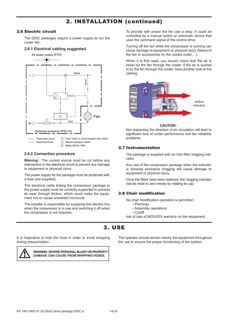
To protect the P.T.O in the event of compressor stalling,
it is necessary to install a torque limiter.
The MOUVEX company shall not be held responsible for
damage resulting from such stalling if this stalling is
caused by wrong manipulation with the compressor or if
no or not the right torque limiter is installed.
The torque limiter will be installed on the compressor
shaft, as illustrated in the photo below.
DDIC packages may be ordered with torque limiters
mounted. Refer to Instructions 1401-B00 TORQUE LIMITER
- MISTRAL B600 TYPHON II.
If the greasing instructions for the universal joint are
not respected, this can lead to ruptures of this uni-
versal joint, as well as property damage and serious
injuries.
2.5.3 Installation of channelling
Channelling connected to the package must be desi-
gned in accordance with regulations to prevent prematu-
re breakdowns on the installation.
In particular, MOUVEX recommends taking the following
precautions:
• Channelling must be supported so as to prevent then
from mechanically loading the inlets and outlets on
the compressor package.
• Inlet and discharge channelling must have a diameter
at least equal to that of inlet and discharge connec-
tions on the compressor package.
• At the inlet, you should limit sources of load loss
(elbows, valves, lengths of channelling…).
Compressor
Torque limiter
A Universal joint angle
0,017 1°
VERY GOOD0,035 2°
0,052 3°
0,070 4°
0,087 5°
0,105 6°
GOOD0,125 7°
0,141 8°
0,158 9°
0,176 10°
0,194 11°
LIMIT
VALUES
0,213 12°
0,231 13°
0,249 14°
0,268 15°
_________
A =√H² + W²L
If H = Zero, A = W / L
If W = Zero, A = H / L
CAUTION
13/18NT 1401-R00 01 20 Direct drive package DDIC e
2. INSTALLATION (continued)
14/18NT 1401-R00 01 20 Direct drive package DDIC e
2. INSTALLATION (continued)
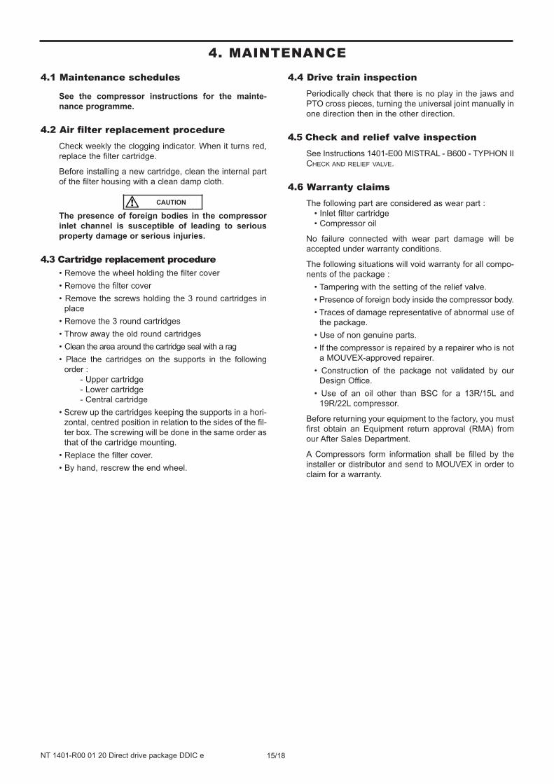
2.6 Electric circuitThe DDIC packages require a power supply to run the
cooler fan.
2.6.1 Electrical cabling suggested
2.6.2 Connection procedure
Warning : The current source must be cut before any
intervention in the electrical circuit to prevent any damage
to equipment or physical injury.
The power supply for the package must be protected with
a fuse (not supplied).
The electrical cable linking the compressor package to
the power supply must be correctly supported to prevent
its wear through friction, which could make the equip-
ment live or cause unwanted microcuts.
The installer is responsible for supplying this electric line
when the compressor is in use and switching it off when
the compressor is not required.
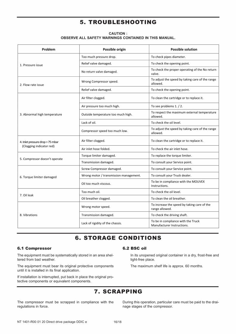
To provide with power the fan use a relay. It could be
controlled by a manual switch or automatic device that
uses the command signal of the control drive.
Turning off the fan while the compressor is running can
cause damage to equipment or physical injury (failure of
the fan or accessories on the cooled outlet …).
When it is first used, you should check that the air is
blown by the fan through the cooler. If the air is sucked
in by the fan through the cooler, have another look at the
cabling.
CAUTION :
Not respecting the direction of air circulation will lead to
significant loss of cooler performance and fan reliability
problems.
2.7 InstrumentationThe package is supplied with an inlet filter clogging indi-
cator.
Any use of the compressor package when the indicator
is showing excessive clogging will cause damage to
equipment or physical injury.
Once the filters have been replaced, the clogging indicator
mat be reset to zero merely by rotating its cap.
2.8 Chair modificationNo chair modification operation is permitted :
• Piercings
• Assembly operations
• Cutoff
risk of loss of MOUVEX warranty on the equipment.
Airflow
direction
It is imperative to hold the hose in order to avoid whipping
during pressurization.
The operator should remain nearby the equipment throughout
the use to ensure the proper functioning of the system.
WARNING: SEVERE PERSONAL INJURY OR PROPERTY
DAMAGE CAN CAUSE FROM WHIPPING HOSES.
3. USE
15/18NT 1401-R00 01 20 Direct drive package DDIC e
4.1 Maintenance schedules
See the compressor instructions for the mainte-
nance programme.
4.2 Air filter replacement procedureCheck weekly the clogging indicator. When it turns red,
replace the filter cartridge.
Before installing a new cartridge, clean the internal part
of the filter housing with a clean damp cloth.
The presence of foreign bodies in the compressor
inlet channel is susceptible of leading to serious
property damage or serious injuries.
4.3 Cartridge replacement procedure• Remove the wheel holding the filter cover
• Remove the filter cover
• Remove the screws holding the 3 round cartridges in
place
• Remove the 3 round cartridges
• Throw away the old round cartridges
• Clean the area around the cartridge seal with a rag
• Place the cartridges on the supports in the following
order :
- Upper cartridge
- Lower cartridge
- Central cartridge
• Screw up the cartridges keeping the supports in a hori-
zontal, centred position in relation to the sides of the fil-
ter box. The screwing will be done in the same order as
that of the cartridge mounting.
• Replace the filter cover.
• By hand, rescrew the end wheel.
4.4 Drive train inspection Periodically check that there is no play in the jaws and
PTO cross pieces, turning the universal joint manually in
one direction then in the other direction.
4.5 Check and relief valve inspectionSee Instructions 1401-E00 MISTRAL - B600 - TYPHON II
CHECK AND RELIEF VALVE.
4.6 Warranty claimsThe following part are considered as wear part :
• Inlet filter cartridge
• Compressor oil
No failure connected with wear part damage will be
accepted under warranty conditions.
The following situations will void warranty for all compo-
nents of the package :
• Tampering with the setting of the relief valve.
• Presence of foreign body inside the compressor body.
• Traces of damage representative of abnormal use of
the package.
• Use of non genuine parts.
• If the compressor is repaired by a repairer who is not
a MOUVEX-approved repairer.
• Construction of the package not validated by our
Design Office.
• Use of an oil other than BSC for a 13R/15L and
19R/22L compressor.
Before returning your equipment to the factory, you must
first obtain an Equipment return approval (RMA) from
our After Sales Department.
A Compressors form information shall be filled by the
installer or distributor and send to MOUVEX in order to
claim for a warranty.
CAUTION
4. MAINTENANCE
16/18NT 1401-R00 01 20 Direct drive package DDIC e
Problem Possible origin Possible solution
1. Pressure issue
Too much pressure drop. To check pipes diameter.
Relief valve damaged. To check the opening point.
No return valve damaged. To check the proper operating of the No return valve.
2. Flow rate issue Wrong Compressor speed. To adjust the speed by taking care of the range
allowed.
Relief valve damaged. To check the opening point.
3. Abnormal high temperature
Air filter clogged. To clean the cartridge or to replace it.
Air pressure too much high. To see problems 1. / 2.
Outside temperature too much high. To respect the maximum external temperature allowed.
Lack of oil. To check the oil level.
Compressor speed too much low. To adjust the speed by taking care of the range allowed.
4. Inlet pressure drop > 75 mbar (Clogging indicator red)
Air filter clogged. To clean the cartridge or to replace it.
Air inlet hose folded. To check the air inlet hose.
5. Compressor doesn’t operate Torque limiter damaged. To replace the torque limiter.
Transmission damaged. To consult your Service point.
6. Torque limiter damaged
Screw Compressor damaged. To consult your Service point.
Wrong motor / transmission management. To consult your Truck dealer.
Oil too much viscous. To be in compliance with the MOUVEX Instructions.
7. Oil leak Too much oil. To check the oil level.
Oil breather clogged. To clean the oil breather.
8. Vibrations
Wrong motor speed. To increase the speed by taking care of the range allowed.
Transmission damaged. To check the driving shaft.
Lack of rigidity of the chassis. To be in compliance with the Truck Manufacturer Instructions.
5. TROUBLESHOOTING
CAUTION :
OBSERVE ALL SAFETY WARNINGS CONTAINED IN THIS MANUAL.
6.1 CompressorThe equipment must be systematically stored in an area shel-
tered from bad weather.
The equipment must bear its original protective components
until it is installed in its final application.
If installation is interrupted, put back in place the original pro-
tective components or equivalent components.
6.2 BSC oilIn its unopened original container in a dry, frost-free and
light-free place.
The maximum shelf life is approx. 60 months.
6. STORAGE CONDITIONS
The compressor must be scrapped in compliance with the
regulations in force.
During this operation, particular care must be paid to the drai-
nage stages of the compressor.
7. SCRAPPING
17/18NT 1401-R00 01 20 Direct drive package DDIC e
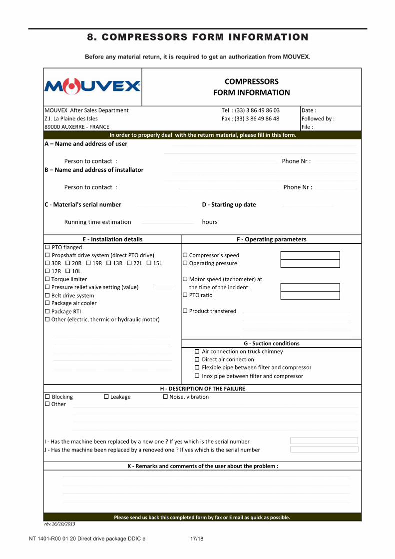
8. COMPRESSORS FORM INFORMATION
MOUVEX After Sales Department Tel : (33) 3 86 49 86 03 Date :Z.I. La Plaine des Isles Fax : (33) 3 86 49 86 48 Followed by :89000 AUXERRE - FRANCE File :
A – Name and address of user
Person to contact : Phone Nr :B – Name and address of installator
Person to contact : Phone Nr :
C - Material's serial number D - Starting up date
Running time estimation hours
PTO flanged Propshaft drive system (direct PTO drive) Compressor's speed 30R 20R 19R 13R 22L 15L Operating pressure 12R 10L Torque limiter Pressure relief valve setting (value) Belt drive system PTO ratio Package air cooler Package RTI Product transfered
Air connection on truck chimney Direct air connectionFlexible pipe between filter and compressorInox pipe between filter and compressor
Blocking Leakage Noise, vibration Other
I - Has the machine been replaced by a new one ? If yes which is the serial numberJ - Has the machine been replaced by a renoved one ? If yes which is the serial number
rév.16/10/2013Please send us back this completed form by fax or E mail as quick as possible.
G - Suction conditions
H - DESCRIPTION OF THE FAILURE
K - Remarks and comments of the user about the problem :
In order to properly deal with the return material, please fill in this form.
E - Installation details F - Operating parameters
COMPRESSORSFORM INFORMATION
Other (electric, thermic or hydraulic motor)
Motor speed (tachometer) at the time of the incident
Before any material return, it is required to get an authorization from MOUVEX.
18/18NT 1401-R00 01 20 Direct drive package DDIC e
Es
t co
nfor
me
aux
disp
ositi
ons
suiv
ante
s :
Dire
ctive
« MAC
HINES
» 2
006/
42/CE et
aux
législa
tions
nationa
les la
tran
sposan
t, po
rtan
t sur
les
dispositifs
de
sécurit
é liés
aux
risqu
es
mécan
ique
s et é
lectriq
ues a
pplicab
les a
ux m
achine
s tou
rnan
tes.
NF EN
809
:200
9 NF EN
167
2-2:20
09
NF EN
ISO
138
57:200
8
NF EN
121
62:200
9
Dire
ctive
« AT
EX »
201
4/34
/UE du
26 février 20
14 et au
x législa
tions
na
tiona
les la
transpo
sant, p
ortant
sur
les ap
pareils
destin
és à
être utilisés
en atmosph
ères
explosibles.
Co
nformité
ob
tenu
e pa
r ap
plication
des
norm
es :
NF EN
112
7-1:19
97
NF EN
134
63-1:200
9 NF EN
134
63-5:200
9
Certificatio
n AT
EX d
élivrée pa
r INER
IS*,
Organ
isme Ce
rtificateur, e
t portant
le
marqu
age suivan
t : (C
)
L’éq
uipe
men
t dé
signé
ci-dessus
doit
impé
rativ
emen
t respecter
les
cond
ition
s d’utilisatio
n AT
EX d
écrites
dan
s no
s no
tices
d’in
struction.
Il doit
être
employ
é conform
émen
t à l’u
tilisa
tion qu
i en a
été pr
évue
de pa
r sa
concep
tion et
sa fa
brication,
et con
form
émen
t aux
normes
en vigueu
r.
Nou
s, sou
ssigné
s, d
éclarons
que
l’éq
uipe
men
t concerné
est
con
form
e au
x Directives
list
ées c
i-dessus e
t aux
normes
app
licab
les s
’y ra
pportant.
Is in
con
form
ity w
ith th
e pr
ovisi
ons o
f the
follo
win
g Dire
ctiv
e:
«
MAC
HIN
ES »
Dire
ctiv
e 20
06/4
2/EE
C as
tra
nspo
sed
by t
he n
atio
nal
legi
slatio
n, c
oncern
ing
safe
ty e
quip
men
ts a
nd a
rran
gem
ents
rel
ativ
e to
m
echa
nica
l and
ele
ctric
risk
s app
licab
le to
rota
tive
mac
hine
s.
NF EN
809
:200
9 NF EN
167
2-2:20
09
NF EN
ISO
138
57:200
8
NF EN
121
62:200
9
« A
TEX
» Di
rect
ive
2014
/34/
EU (26
Feb. 20
14)
as tra
nspo
sed
by t
he
natio
nal l
egisl
atio
n, c
oncern
ing
equi
pmen
t in
tend
ed t
o be
use
d in
exp
losiv
e at
mos
pher
es. C
onform
ity o
btai
ned
by a
pplic
atio
n of
the
stan
dard
s :
NF EN
112
7-1:19
97
NF EN
134
63-1:200
9 NF EN
134
63-5:200
9
ATEX
Ce
rtifi
catio
n de
liver
ed
by
INER
IS*,
N
otifi
ed
Body
, an
d w
ith
the
follo
win
g m
arki
ng: (C)
The
equi
pmen
t in
dica
ted
abov
e m
ust
impera
tivel
y co
mpl
y w
ith t
he A
TEX
cond
ition
s of
use
des
crib
ed i
n ou
r In
stru
ctio
n bo
ok.
It m
ust
be u
sed
accord
ing
to t
he f
ores
een
use
by i
ts d
esig
n an
d its
man
ufac
turin
g, a
nd
accord
ing
to th
e curr
ent s
tand
ards.
We,
und
ersig
ned,
dec
lare
tha
t th
e co
ncer
ned
equi
pmen
t is
in c
onform
ity
with
the
Dire
ctiv
es li
sted
abo
ve a
nd in
the
appl
icab
le st
anda
rds i
n forc
e.
den
Best
imm
unge
n der n
achs
tehe
nden
Ric
htlin
ien
ents
pric
ht:
„M
asch
inen
-Ric
htlin
ie“
2006
/42/
EEC
wie
um
gese
tzt i
m n
atio
nale
n Re
cht
hins
icht
lich
der A
usrü
stun
gssic
herh
eit u
nd S
icherh
eitsvork
ehru
ngen
bez
ogen
au
f m
echa
nisc
he u
nd e
lektris
che
Risik
en,
die
für ro
tiere
nde
Mas
chin
en
gelte
n. NF EN
809
:200
9 NF EN
167
2-2:20
09
NF EN
ISO
138
57:200
8
NF EN
121
62:200
9
„A
TEX“
Ri
chtli
nie
2014
/34/
EU
(26.
Fe
b. 20
14)
wie
um
gese
tzt
im
natio
nale
n Re
cht
in
Bezu
g au
f Au
srüs
tung
en
für
den
Eins
atz
in
expl
osio
nsge
fähr
deter
Atm
osph
äre.
Die
Kon
form
ität
hat
Geltu
ng d
urch
An
wen
dung
folg
ender N
orm
en:
NF EN
112
7-1:19
97
NF EN
134
63-1:200
9 NF EN
134
63-5:200
9
Die
ATEX
-Zer
tifizi
erun
g w
urde
von
der
ben
annt
en S
telle
INER
IS*
erte
ilt, u
nd
mit
folg
ender K
ennz
eich
nung
: (C
)
Obe
n st
ehen
d be
zeic
hnet
e Au
srüs
tung
mus
s un
bedi
ngt
den
in u
nser
en
Betri
ebsa
nlei
tung
en
besc
hrie
bene
n AT
EX
Anw
endu
ngs-
bedi
ngun
gen
ents
prec
hen.
Sie
ist
ents
prec
hend
dem
dur
ch K
onstru
ktio
n un
d Fa
brik
atio
n vorg
eseh
enen
Ver
wen
dung
szw
eck
und
ents
prec
hend
den
gel
tend
en N
orm
en
einz
uset
zen.
Die
Unt
erze
ichn
er e
rkläre
n, d
ass
die
beze
ichn
ete
Ausr
üstu
ng d
en o
ben
aufg
eführt
en R
ichtli
nien
und
den
die
sbez
üglic
h ge
ltend
en N
orm
en e
ntspric
ht.
DE
CLA
RA
TIO
N U
E D
E C
ON
FOR
MIT
E
EU C
ERTI
FIC
ATE
OF
CO
NFO
RM
ITY
– EU
KO
NFO
RM
ITÄ
TSER
KLÄ
RU
NG
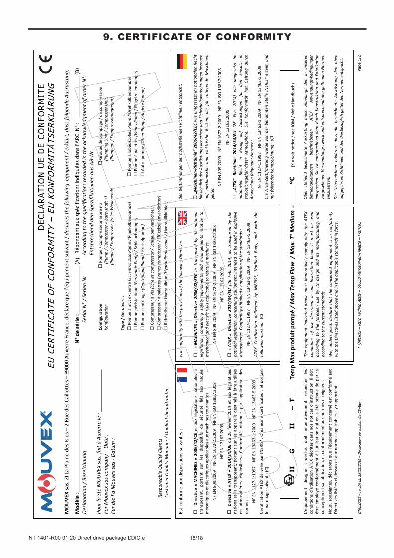
MOU
VEX sas,
ZI La Plaine
des
Isles –
2 Rue
des
Caillottes
– 890
00 Auxerre
France,
déclare
que
l’éq
uipe
men
t suivant
/ de
clar
es th
e fo
llow
ing
equ
ipm
ent /
erk
lärt
, das
s fol
gend
e Au
srüs
tung
:
Mod
èle :
N
° de série
:
(A
) R
épon
dant
aux
spécificatio
ns indiqu
ées d
ans l’ARC
N° :
(B
) De
signa
tion / B
ezei
chnu
ng
Ser
ial N
° / S
erie
n Nr
Acc
ordi
ng to
the
spec
ifica
tions
record
ed in
the
ackn
owle
dgm
ent o
f ord
er N
°:
E
ntspre
chen
d de
n Sp
ezifi
katio
nen
aus A
B-Nr :
Po
ur la
Sté
MO
UVE
X sa
s, fa
it à
Auxerr
e le
:
For M
ouve
x sa
s com
pany
– D
ate
: Fur d
ie F
a M
ouve
x sa
s - D
atum
:
Resp
onsa
ble
Qua
lité
Clie
nts
Cust
omer
Qua
lity
Man
ager
/ Q
ualit
ätsb
eauf
trag
ter
II
__ G
___
_ I
I __
– T
__
Tem
p Max
produ
it po
mpé
/ M
ax T
emp
Flow
/ M
ax. T
° Med
ium
= _
____
°C
(
X = voir no
tice / s
ee IO
M / sie
he Han
dbuch)
Configuration:
Po
mpe
/ Co
mpresseur
arbre
nu
Grou
pe de po
mpa
ge / de
com
pressio
n Ko
nfig
urat
ion
(Pum
p / C
ompr
essor «
bar
e-sh
aft »
)
(P
umpi
ng U
nit /
Com
pres
sor U
nit)
(Pum
pe /
Kom
pres
sor,
frei
es W
elle
nend
e
(P
umpe
n- /
Kom
pres
sora
ggre
gat)
Type
/ G
erät
eart
:
Pom
pe à
mvt
excen
tré
(Ecc
entr
ic D
isc P
ump / R
ingkolbe
npum
pe)
Pom
pe à
lobe
s (Lo
bes P
ump / D
rehkolbe
npum
pe)
Pom
pe p
éristaltiq
ue (P
erist
altic
Pum
p / S
chlauchp
umpe
)
Pom
pe à
palettes (
Vane
s Pum
p / F
lügelze
llenp
umpe
) Pom
pe cen
trifu
ge (C
entr
ifuga
l Pum
p / K
reise
lpum
pe)
Autre
pom
pe (O
ther
Pum
p / A
nder
e Pu
mpe
)
Com
presseur
à Vis
(Scr
ews c
ompr
essor /
Schraub
enverdichter
) Com
presseur
à palettes (
Vane
s com
pres
sor /
Flügelze
llenverdichter)
Re
froidisseu
r Hydraulique
(Hydra
ulic
oil
cool
er / Hy
drau
likkühler
)
CTRL
.D02
5 –
rév.
04 d
u 25
/05/
2016
– D
écla
ratio
n de
con
form
ité C
E-At
ex
*
(IN
ERIS
–Pa
rc T
echn
o At
ala
–60
550
Vern
euil-
en-H
alat
te –
Fran
ce).
Pag
e 1/
2
9. CERTIFICATE OF CONFORMITY


