
Advances in Concrete Construction, Vol. 8, No. 3 (2019) 165-172
DOI: https://doi.org/10.12989/acc.2019.8.3.165 165
Copyright © 2019 Techno-Press, Ltd. http://www.techno-press.org/?journal=acc&subpage=7 ISSN: 2287-5301 (Print), 2287-531X (Online)
1. Introduction
As defined by the American Society of Civil Engineers,
progressive collapse is an expanding rudimentary rupture
from one component to another which leads to total
collapse of a structure or a major part of it ASCE7 (2002).
Progressive collapse matter chronicles, as an engineering
problem caused the collapse of Ronan Point building in
1968. This 22-story building was made of premade bearing
walls screwed together. A gas explosion on the 18th floor
only destructed one of the premade walls in that floor. This
destruction collapsed upper roofs on the bottom floors till
the ground level which made it a progressive collapse
(NIST2007). Then, on 25 January 1971, two third of the 16-
story Finance building in Boston which was under
construction by King and Dellate collapsed and killed 4
people, (2004). In another incident in 1995, a car bomb
exploded near Alfred Mora building which collapsed almost
half of the roof due to progressive collapse effect
(genecorely et al. 1998). The last incident caused by
progressive collapse was the collapse of 101-story twin
towers of New York on 11 September 2001. In this
catastrophic incident, two passenger airplanes crashed into
the towers and 2830 people were killed (Zdenek and
Verdure 2007). There are lots of regulations to study
progressive collapse. The regulations of general service
administration of USA and department of defense offer
solutions to increase indeterminacy in structures,
transferring loads from detours and, increasing local
Corresponding author, Ph.D.
E-mail: [email protected]
resistance in structures (GSA2003, DoD 2010). In addition,
most static analysis procedures do not model the impacts of
failed members after the initial partial collapse (Kokot et al.
2012, Ruth et al. 2006, Wang and Li 2011). In order to use
concrete structures safely, restoration and reinforcement is
necessary. One economic method is to use FRP plates (Fam
and Rikalla 2003). FRP materials had been used since the
mid-1980s for reinforcing concrete structures (Meier et al
1993). FRP materials are composite materials with high
resistance yarns having different heat expansion coefficient
in two directions along with yarns and vertical to them that
under heat loading act in an orthotropic way, so does not get
damage under heat strains (Guideline for Design
Specification of strengthening 2006).
There are many studies on progressive collapse in
reinforced concrete structures which we will peruse some of
them. Bao et al. (2008) offered a two-dimensional macro
model consisted of 2 beams and 3 columns in order to
simulate the non-linear behavior of beam-column
connections in reinforced concrete structures. Comparing
their results to experimental results, they found that using
macro model is a proper approach to analyze progressive
collapse (Bao et al. 2008). Tsai and Lin studied an 11-Story
concrete building in Taiwan using seismic design and
column failure at the bottom floor with 3 types of analyzes
(static, nonlinear static and nonlinear dynamic). They found
that seismic design is efficient in decreasing progressive
collapse in concrete buildings (Tsai and Lin 2008).
Gregorio and et.al focused on the analysis of a specific
volcanic event constituted by the pyroclastic deposits,
falling on the roofs due to gravity, the so-called air falls
deposits (Gregorio et al. 2010). Ceroni studied concrete
beams reinforced with FRP and derived that the load
resistance of concrete beams reinforced with FRP increase
Numerical study of progressive collapse in reinforced concrete frames with FRP under column removal
J. Esfandiari and M.K. Latifi
Department of Civil Engineering, Kermanshah Branch, Islamic Azad University, Kermanshah, Iran
(Received March 4, 2019, Revised May 8, 2019, Accepted May 13, 2019)
Abstract. Progressive collapse is one of the factors which if not predicted at the time of structure plan; its occurrence will lead
to catastrophic damages. Through having a glance over important structures chronicles in the world, we will notice that the
reason of their collapse is a minor damage in structure caused by an accident like a terrorist attack, smashing a vehicle, fire, gas
explosion, construction flaws and its expanding. Progressive collapse includes expanding rudimentary rupture from one part to
another which leads to total collapse of a structure or a major part it. This study examines the progressive collapse of a 5-story
concrete building with three column eliminating scenarios, including the removal of the corner, side and middle columns with
the ABAQUS software. Then the beams and the bottom of the concrete slab were reinforced by (reinforcement of carbon fiber
reinforced polymer) FRP and then the structure was re-analyzed. The results of the analysis show that the reinforcement of
carbon fiber reinforced polymer sheets is one of the effective ways to rehabilitate and reduce the progressive collapse in concrete
structures.
Keywords: progressive collapse; concrete frame; column elimination; reinforcement; FRP
J. Esfandiari and M.K. Latifi
from 26% up to 50% but this quantity for steel beams is less
than 1% (Ceroni 2012). Hoda Helmy and et. al in a study,
analyzed progressive collapse in a reinforced concrete
structure with shear walls. They investigated eliminating
side and corner columns and concluded that, not
considering the slab effect will lead to incorrect behavior of
structure and uneconomical plan (Helmy et al. 2012). In
order to improve the reliability of the modeling procedure,
researchers also employed methods such as robustness
evaluation indeterminacy concept and vulnerability
assessment of the structural system (Formisano et al. 2015).
Ren et al. studied the resistance against progressive collapse
in concrete slabs. In the study two concrete frames, one
with and one without the slab had been analyzed and the
middle column eliminated. The model was loaded with a
200-ton jack. The effects of two conditions with and
without concrete slab were investigated. Based on the
results obtained, considering the effect of Concrete slab
increased resistance by 45.40% compared with not
considering the concrete slab against progressive collapse.
(Ren et al. 2014). Formisano et al. studied a research
activity concerning the seismic behaviour of framed
structures after damages deriving from application of an
exceptional load Based on the results of a pushover
analysis, a theoretical formulation to evaluate a simplified
force-displacement curve for seismic appraisement of a
structure damaged from an extreme event is reported
(Formisano et al. 2016).
Progressive collapse is an overall structural response
which involves both material and geometrical nonlinearity
of structural members. Due to the complexity, it is
necessary to decompose overall structures into multi-story,
single-story and beam-column connection levels to obtain
an in-depth understanding of their load-transfer
mechanisms, load and deformation capacities. Reinforced
concrete (RC) framed structures are one of the widely used
structural systems. Over the last decade, a great many
efforts have been dedicated to investigating the progress
collapse performance of single-story RC beam-column
substructures (Yu and Tan 2017).
In nature, progressive collapse is a dynamic response.
However, the dynamic tests of RC beam-column
substructures due to middle column removal by contact
detonation and by free-fall have indicated that the failure
patterns in the dynamic tests are identical to those in quasi-
static tests, and thus the quasi-static results are capable of
representing progressive collapse performance of RC
substructures (Pham and Tan 2017). Ferraioli and et.al
studied a design procedure that combines both progressive
collapse design under column removal scenario and
capacity design to produce the hierarchy of design
strengths. The proposed procedure was applied to two
typical steel framed building using linear static, nonlinear
static and nonlinear dynamic analysis. The results showed
that it is unsafe to assume that a structure designed for
seismic loads can withstand accidental or abnormal load
conditions (Ferraioli et al. 2018).
In this study, we pursue the effect of using CFRP on
reinforcing the structure against progressive collapse. For
this purpose, a 5-story building is modeled using finite
element software, ABAQUS. Comprehensive research was
conducted on three positions elimination including: corner,
side and middle in each floor using nonlinear dynamic
analysis. Then, the beams and the underside of the concrete
slab were reinforced using CFRP sheets with a total
thickness of 5mm. The effect of CFRP reinforcement on
displacement and bearing capacity was investigated.
2. Development and validation of the models used
To verify the results obtained from ABAQUS/CAE, a
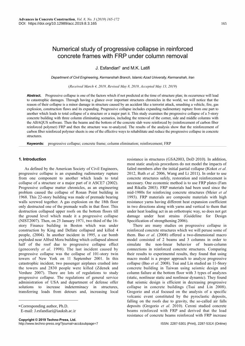
(a) Seismic specimen S1
Fig. 1 Details of reinforcement and loading of the experimental model (Yu and Tan 2011)
166

Numerical study of progressive collapse in reinforced concrete frames with FRP under column removal
Fig. 2 Details of reinforcement and loading of the
experimental model (Yu and Tan 2011)
Fig. 3 column placement and column eliminating position
plan
Frame studied by Yu and Tan (2011) was selected. The test
model includes two samples with seismic design and
without seismic design. Modeling software is modeled with
seismic design. For this purpose, concrete with compressive
strength of 31.2 MPa was used with rebar with a yield stress
of 310-511 MPa . Fig. 1 shows details of reinforcement and
loading of the experimental model. Fig. 2 shows the results
of experimental and numerical modeling of the Progressive
collapse in the form of displacement-force chart. As shown
in the figure, there is a good agreement between the
numerical and experimental modeling. The ultimate loads in
the analytical and experimental models were 41.94 and 41.6
kN, respectively.
3. Modeling
In this study, A 5-story residential building in Sanandaj
city was selected as the base model. The residential building
with five floors is constructed with an area of 167 m2 in
each floor. The story height was 3200 mm. The building
was designed with a concrete structure with an average
ductility according to ACI-08 Regulation using ETABS.
The building consisted of 6000 mm longitudinal and lateral
outfall with the position of eliminating columns, as shown
in Fig. 3.
Fig. 4 Post failure stress-strain curve (Abaqus analysis
user’s manual 6.10)
Table 1 Properties of the materials used
Property Concrete CFRP Epoxy Steel
Density kN/m3 24 16 - 78.5
Yield Strength, fy (MPa) - - - 400
Modulus of elasticity (GPa) 23.39 120 7 210
Tensile Strength, ft (MPa) 3 3800 25 570
Compressive Strength, f'c (MPa) 25 - 70 -
Poisson’s ratio 0.2 0.3 0.3 0.3
Table 2 Section specifications and beam reinforcement
(mm)
Section
Floor
Size Section Top
rebar
Bottom
rebar stirrups
Width Depth
1 500 300 20ᶲ5 20ᶲ3 10ᶲ
2 500 300 20ᶲ5 20ᶲ3 10ᶲ
3 400 300 20ᶲ5 20ᶲ3 10ᶲ
4 400 300 20ᶲ5 20ᶲ3 10ᶲ
5 400 300 20ᶲ5 20ᶲ3 10ᶲ
In this study, nonlinear dynamics finite element analyses
were performed using ABAQUS. Concrete compressive
strength is 25 MPa with modulus of elasticity of 23.39 GPa
and steel ultimate strength of 570 GPa. The properties of
the materials are described in Table1. Also, concrete slab
thickness is considered 100 mm. In this study, Brittle
Cracking of concrete is used for modeling concrete
behavior. In reinforced concrete the specification of post
failure behavior generally means giving the post failure
stress as a function of strain across the crack Fig. 4. Where
𝜎𝑡𝐼 is remaining direct stress after cracking, 𝑒𝑛𝑛
𝑐𝑘 is direct
cracking strain. In the model, it is assumed that compressive
behavior of concrete is always linear and also the elastic
behavior that presents the material behavior before cracking
must be defined. However, it is defined for reinforced
concrete; it can also be defined for not reinforced concrete.
There is possibility of deleting element based on breaking
damage criterion. For failure criteria at any time in any
direction strain amount reaches 0.001 concrete elements of
the model will be deleted. In the study, outfall beams which
their columns are eliminated get wrapped completely.
Reinforcement details and beam section dimensions are
shown in Table 2. Reinforcement details and column section
dimensions and specifications are shown in Table 3. The
stirrups distance is considered to be 100 mm. The 3D model
167
J. Esfandiari and M.K. Latifi
Table 3 Reinforcement and column section dimensions and
specifications (mm)
Section
Floor
Size Section Rebar stirrups
Width Depth
1 450 450 20ᶲ3 10ᶲ
2 450 450 20ᶲ3 10ᶲ
3 450 450 20ᶲ3 10ᶲ
4 450 450 20ᶲ3 10ᶲ
5 450 450 20ᶲ3 10ᶲ
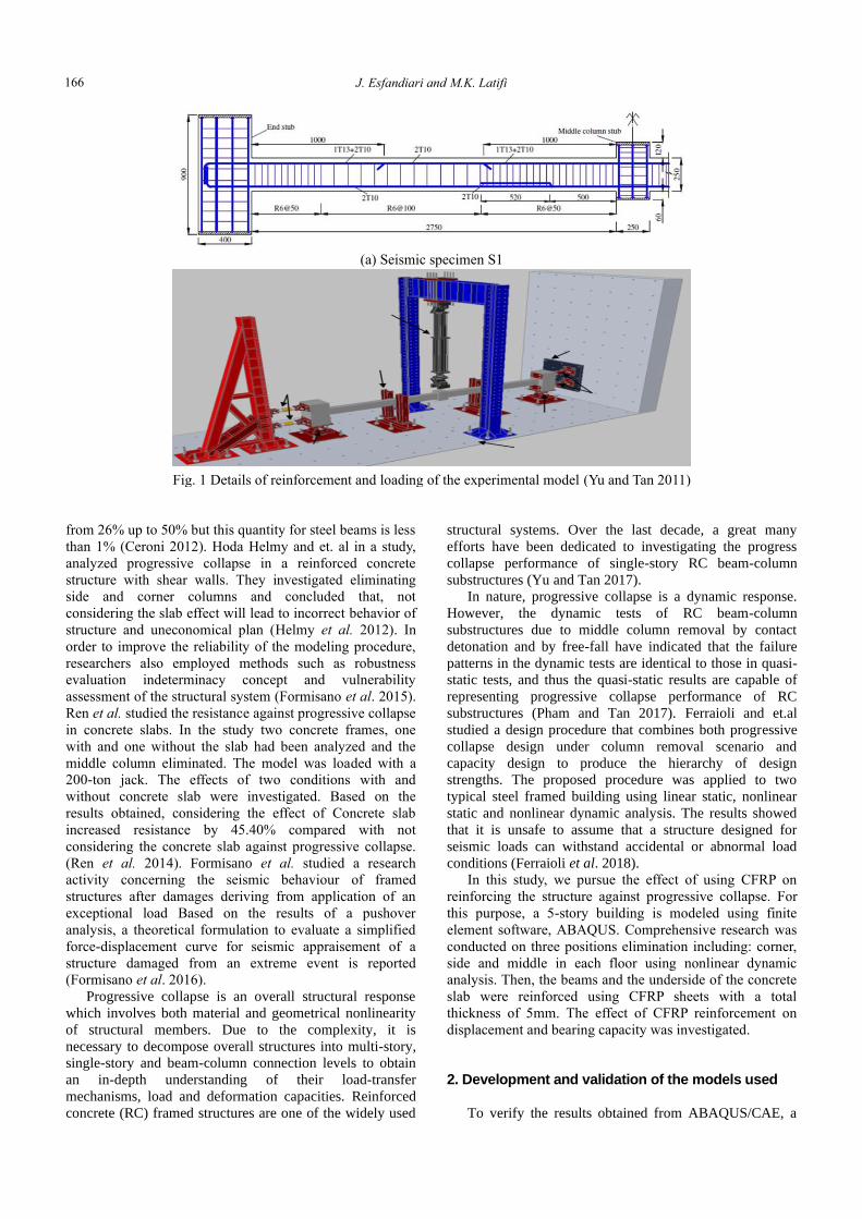
Fig. 5 3D model of the structure in ABAQUS
Fig. 6 Reinforcement pattern of specimens
of the structure in ABAQUS software is shown in Fig. 5.
For the purpose of wrapping of all beams, 5 CFRP
layers with total 5 mm thickness are used. The CFRP sheets
used in this study have bidirectional fibers with wrapping
angles of 0° and 90°. The specimens with a 5770×5770
mm, For the underside of concrete slabs and 5500×500 mm,
and 5500×400 mm, 5500×300 mm, for beams from the first
floor to the fifth floor. Fig. 6 shows Reinforcement pattern
of specimens.
A uniform dead load of 2.0 kN/m is used for non-
structural exterior components applied on the perimeter
frames. The live load is 2.5 kN/m2, and the total dead load
including self-weight is 7.1 kN/m2.
In the phenomenon of progressive collapse, a member of
the main carrier of the structure is disrupted by the load it
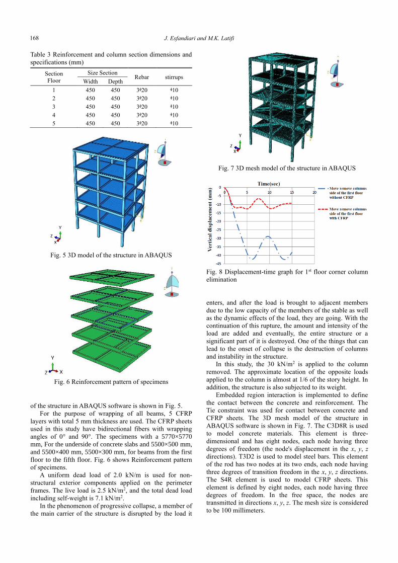
Fig. 7 3D mesh model of the structure in ABAQUS
Fig. 8 Displacement-time graph for 1st floor corner column
elimination
enters, and after the load is brought to adjacent members
due to the low capacity of the members of the stable as well
as the dynamic effects of the load, they are going. With the
continuation of this rupture, the amount and intensity of the
load are added and eventually, the entire structure or a
significant part of it is destroyed. One of the things that can
lead to the onset of collapse is the destruction of columns
and instability in the structure.
In this study, the 30 kN/m2 is applied to the column
removed. The approximate location of the opposite loads
applied to the column is almost at 1/6 of the story height. In
addition, the structure is also subjected to its weight.
Embedded region interaction is implemented to define
the contact between the concrete and reinforcement. The
Tie constraint was used for contact between concrete and
CFRP sheets. The 3D mesh model of the structure in
ABAQUS software is shown in Fig. 7. The C3D8R is used
to model concrete materials. This element is three-
dimensional and has eight nodes, each node having three
degrees of freedom (the node's displacement in the x, y, z
directions). T3D2 is used to model steel bars. This element
of the rod has two nodes at its two ends, each node having
three degrees of transition freedom in the x, y, z directions.
The S4R element is used to model CFRP sheets. This
element is defined by eight nodes, each node having three
degrees of freedom. In the free space, the nodes are
transmitted in directions x, y, z. The mesh size is considered
to be 100 millimeters.
168

Numerical study of progressive collapse in reinforced concrete frames with FRP under column removal
Fig. 9 Displacement-time graph for 1st floor side column
elimination
Fig. 10 Displacement-time graph for 1st floor middle
column elimination
Fig. 11 Displacement-force graph for 1st floor corner
column elimination
4. Results
The final analyze results of eliminating 3 column
position is defined as eliminating side, middle and corner
columns. Displacement-time graph of eliminating column at
1st floor is shown in Figs. 8, 9, and 10 for instance.
Eliminating column force-displacement graph for the 1st
floor, both in reinforced and no reinforced mood, are shown
in Figs. 11, 12 and 13.
To calculate the amount of displacement in each mode,
the displacement of the upper node of the removed column
is considered. As presented in Fig. 10, the maximum
displacement at non CFRP is in eliminating middle column
of the 1st floor which is 280 mm and the minimum is 20 mm
Fig. 12 Displacement-force graph for 1st floor side column
elimination
Fig. 13 Displacement-force graph for 1st floor middle
column elimination
Table 4 Displacement and force quantities in 1st floor
Position
remove
columns
Floor
Displacement
without CFRP
(mm)
Displacement
with CFRP
(mm)
Force
without
CFRP
(kN)
Force
with
CFRP
(kN)
Corner First 20 12 3879.59 3976.82
Side First 42.4 12.4 3656.58 3770.85
Middle First 280 60 3247.15 3395.72
for eliminating corner column. For the CFRP mode these
numbers decrease 60 and 12 mm for eliminating middle and
corner columns, respectively. In the case of non-reinforcing
mid-column removal with CFRP, due to a significant
increase in displacement, the structure will be destroyed.
However, in CFRP-reinforced mode, the displacement rate
will be significantly reduced and the structural stability will
be maintained. To calculate the force values, the number of
response columns is considered to be eliminated. For non
CFRP Force-Displacement graph, eliminating corner
column has the maximum force of 3879.59 kN and the
minimum force is 3247.15 kN for eliminating middle
column, these quantities for CFRP mode increase 3976.82
and 3395.72 kN, respectively. Displacement and force
quantities in 1st floor are shown in Table 4.
Displacement and force quantities of 2nd floor are shown
in Table 5.
As presented in Table 5, the minimum displacement is
for eliminating corner column and the maximum is for
169
J. Esfandiari and M.K. Latifi
Table 5 Displacement and force quantities in 2nd floor
Position
remove
columns
Floor
Displacement
without
CFRP (mm)
Displacement
with CFRP
(mm)
Force
without
CFRP
(kN)
Force
with
CFRP
(kN)
Corner Second 23 13 4006.22 4029.26
Side Second 49.9 15.1 2717.31 2962.90
Middle Second 110.7 72.4 2888.81 2968.04
Table 6 Displacement and force quantities in 3rd floor
Position
remove
columns
Floor
Displacement
without CFRP
(mm)
Displacement
with CFRP
(mm)
Force
without
CFRP
(kN)
Force
with
CFRP
(kN)
Corner Third 32.9 16.3 3999.57 4033.20
Side Third 67.7 20 3785.40 3967.16
Middle Third 133.5 98.1 3853.86 3942.30
Table 7 Displacement and force quantities in 4th floor
Position
remove
columns
Floor
Displacement
without CFRP
(mm)
Displacement
with CFRP
(mm)
Force
without
CFRP
(kN)
Force
with
CFRP
(kN)
Corner Fourth 31.7 17.6 3935.10 3980.65
Side Fourth 67 21.8 3942.41 3966.77
Middle Fourth 119 93 3955.23 4045.49
middle one. Also, corner column elimination has the
maximum force and the minimum is for middle column
elimination at non CFRP mode. In CFRP mode, the
minimum displacement is for corner elimination and the
maximum belongs to middle one. Also, the maximum force
is for corner column elimination and the minimum force
belongs to side one. Force-displacement quantities in 3rd
floor are shown in Table 6.
As presented in Table 6, the minimum displacement
belongs to corner column elimination and the maximum is
for the middle one. Also the maximum force belongs to
corner column elimination and the minimum is for middle
one, in non CFRP mode. In CFRP mode, the minimum
displacement belongs to corner column elimination and the
maximum is for the middle one. Also the maximum force
belongs to corner column elimination and the minimum is
for side one. Force-displacement quantities in 4rd floor are
shown in Table 7.
As presented in table 7, the minimum displacement is
for eliminating corner column and the maximum is for
middle one. Also, middle column elimination has the
maximum force and the minimum is for corner column
elimination at non CFRP mode. In CFRP mode, the
minimum displacement is for corner elimination and the
maximum belongs to middle one. Also, the maximum force
is for corner column elimination and the minimum force
belongs to side one. Displacement and force quantities of
5th floor are shown in Table 8.
As presented in table 8, the minimum displacement is
for eliminating corner column and the maximum is for
middle one. As it can be seen in table 8, there is no
considerable difference between reinforced and no
Table 8 Displacement and force quantities in 5th floor
Position
remove
columns
Floor
Displacement
without
CFRP
(mm)
Displacement
with CFRP
(mm)
Force
without
CFRP
(kN)
Force
with
CFRP
(kN)
Corner Fifth 22.9 14.9 4131.67 4153.13
Side Fifth 69.7 29.8 4110.68 4206.38
Middle Fifth 135.7 128.5 4171.04 4171.67
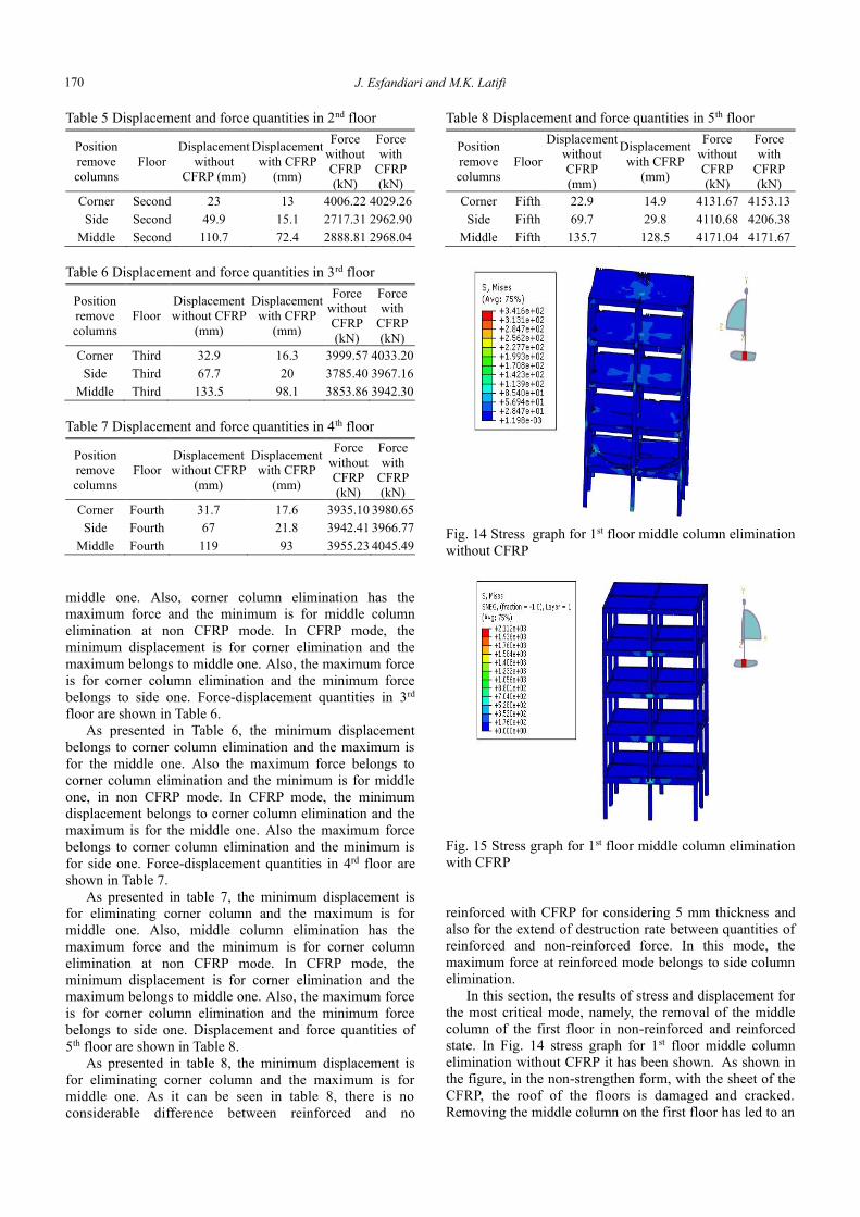
Fig. 14 Stress graph for 1st floor middle column elimination
without CFRP
Fig. 15 Stress graph for 1st floor middle column elimination
with CFRP
reinforced with CFRP for considering 5 mm thickness and
also for the extend of destruction rate between quantities of
reinforced and non-reinforced force. In this mode, the
maximum force at reinforced mode belongs to side column
elimination.
In this section, the results of stress and displacement for
the most critical mode, namely, the removal of the middle
column of the first floor in non-reinforced and reinforced
state. In Fig. 14 stress graph for 1st floor middle column
elimination without CFRP it has been shown. As shown in
the figure, in the non-strengthen form, with the sheet of the
CFRP, the roof of the floors is damaged and cracked.
Removing the middle column on the first floor has led to an
170

Numerical study of progressive collapse in reinforced concrete frames with FRP under column removal
Fig. 16 Displacement graph for 1st floor middle column
elimination without CFRP
increase in tension and failure in the column removal area.
In Fig. 15 Stress graph for 1st floor middle column
elimination without CFRP it has been shown. As shown in
the figure, in the strengthen form, with the sheet of the
CFRP, the roofs of the floors of the damage and cracking
floors has decreased and the roof remains healthy. In this
case, the stress is tolerated by the sheets of CFRP, which
leads to a reduction in the stresses on the structure.
In Fig. 16 Displacement graph for 1st floor middle
column elimination without CFRP has been shown. As
shown in the figure without strengthen, removing the
column in the middle of the ceiling leads to an increase in
the displacement in the floors, and the deformation causes
cracking of the roof. As shown in Fig. 16, in the case of no
reinforcement, elimination of the middle column on the first
floor increases the displacement of the ceiling of the upper
floors. With increasing displacement, the roof of the first
floor and other floors have been cracked. Also in the joints,
a beam to the column and the connection of the column to
the cracking roof has occurred. As the displacement
increase continues due to the removal of the middle column,
the entire structure will collapse.
In Fig. 17 Displacement graph for 1st floor middle
column elimination without CFRP has been shown. As
shown in the figure shown in the strengthen mode, with
removing the column in the middle of the roof, the level of
displacement in the floors is reduced to the previous
position and leads to a reduction in the cracking of the roof.
As shown in Fig. 17, when reinforced with CFRP, the
removal of the middle column on the first floor reduces the
displacement of the ceiling of the upper floors. With a
decrease in displacement resulting from the roof of the first
floor and other classes, it is not damaged. Also observed, it
remains stable with decreasing displacement of other
structural regions and the stability of the structure is
preserved. However, nowadays a general theory regarding
the study of robustness and progressive (or
disproportionate) collapse topics does not exist. In fact, if
qualitative study approaches of considered phenomena are
very diffused, no general quantitative recommendations to
evaluate structural robustness have been yet implemented.
Fig. 17 Displacement graph for 1st floor middle column
elimination with CFRP
In general, there are three alternative approaches to
disproportionate collapse resistant design: improved
interconnection or continuity, notional element removal and
key element design. Nevertheless, no general criteria to
quantify these structural evaluation approaches under
extreme or unforeseen events have been implemented
(Formisano and. Mazzolani 2012).
Therefore, the present paper attempts to consider an
innovative method for the resistance of the structure to
progressive collapse.
5. Conclusions
In the present paper, a 5 story concrete building were
studied by 3 different positions of eliminating columns in
each floor and, in the following, reinforcing of outfall
beams which their columns are eliminated, with CFRP
sheets. According to the results, it can be concluded that:
• In the position of column elimination, middle column
elimination of 1st floor has a critical position and the
maximum displacement.
• And, corner column elimination has the least critical
position for displacement.
• According to the analyses, 1st, 3rd and 5th floors have
more critical positions compare to 2nd and 4th against
progressing collapse.
• Also, it can be derived that using CFRP sheet
decreases displacement and, with respect to column
elimination position, has the greatest impact on first and
second floors and the least on the 5th floor.
• Dimensions of beams and columns have great impact
on studying progressing collapse in a way that,
decreasing their dimensions in third to fifth floor
provides context for progressing collapse.
• In the case of removal of the column in the middle of
the first floor, the concrete roof in elastic area has the
highest stresses and cracking. By reducing the strength
of the beams with the CFRP sheet, the amount of
cracking and Stress significantly decreases.
171

J. Esfandiari and M.K. Latifi
References Bao, Y. (2008), Macromodel-based Progressive Collapse
Simulation of Reinforced Concrete Structures, University of
California, Davis.
Bažant, Z.P. and Verdure, M. (2007), “Mechanics of progressive
collapse: Learning from World Trade Center and building
demolitions”, J. Eng. Mech., 133(3), 308-319.
Ceroni, F. (2011), “Experimental performances of Rc beams
strengthened with FRP materials”, Constr. Mater., 24, 1547-
1559.
Corley, W.G., Sr, P.F.M., Sozen, M.A. and Thornton, C.H. (1998),
“The Oklahoma City bombing: Summary and recommendations
for multihazard mitigation”, J. Perform. Constr. Facil., 12(3),
100-112.
De Gregorio, D., Faggiano, B., Formisano, A. and Mazzolani,
F.M. (2010), “Air fall deposits due to explosive eruptions:
Action model and robustness assessment of the Vesuvian roofs”,
COST ACTION C26: Urban Habitat Constructions under
Catastrophic Events - Proceedings of the Final Conference,
507-512.
DoD, U.S. (2009), Design of Buildings to Resist Progressive
Collapse, US Department of Defense, Washington, DC, USA.
Ellingwood, B.R., Smilowitz, R., Dusenberry, D.O., Duthinh, D.,
Lew, H.S. and Carino, N.J. (2007), “Best practices for reducing
the potential for progressive collapse in buildings”, No. NIST
Interagency/Internal Report (NISTIR)-7396.
Engineers, A.S. (2010), “Minimum design loads for buildings and
other structures”, Reston, Virginia: ASCE.
Fam, A.Z. and Rizkalla, S.H. (2001), “Confinement model for
axially loaded concrete confined by circular fiber-reinforced
polymer tubes”, Struct. J., 98(4), 451-461.
Ferraioli, M., Lavino, A., Mandara, A., Donciglio, M. and
Formisano, A. (2018), “Seismic and robustness design of steel
frame buildings”, Key Eng. Mater., 763, 116-123.
Formisano, A., Iazzetta, G., Marino, G., Fabbrocino, F. and
Landolfo, R. (2016), “Seismic residual capacity assessment of
framed structures damaged by exceptional actions”, ECCOMAS
Congress 2016 - Proceedings of the 7th European Congress on
Computational Methods in Applied Sciences and Engineering,
3, 4942-4958.
Formisano, A., Landolfo, R. and Mazzolani, F.M. (2012),
“Progressive collapse and robustness of steel framed
structures”, Proceedings of the Eleventh International
Conference on Computational Structures Technology, Civil-
Comp Press, Stirlingshire, Scotland.
Formisano, A., Landolfo, R. and Mazzolani, F.M. (2015),
“Robustness assessment approaches for steel framed structures
under catastrophic events”, Compu. Struct., 147, 216-228.
GSA, U. (2003), “Progressive collapse analysis and design
guidelines for new federal office buildings and major
modernization projects”, Washington, DC.
Helmy, H., Salem, H. and Mourad, S.H. (2012), “Progressive
collapse assessment of framed reinforced concrete structures
according to UFC quidelines for alternative path method”, Eng.
Struct., 42, 127-141.
King, S. and Delatte, N.J. (2004), “Collapse of 2000
Commonwealth Avenue: punching shear case study”, J.
Perform. Constr. Facil., 18(1), 54-61.
Kokot, S., Anthoine, A., Negro, P. and Solomos, G. (2012),
“Static and dynamic analysis of a reinforced concrete flat slab
frame building for progressive collapse”, Eng. Struct., 40, 205-
217.
Meier, U., Deuring, M., Meier, H. and Schweglar, G. (1993),
“CFRP bonded sheets, Fiber-Reinforced-Plastic (FRP)
reinforced for concrete structure: Properties and applications”,
Ed. A. Nani, Elsevirscience, Amsterdam, The Nethrlands.
Pham, A.T. and Tan, K.H. (2017), “Experimental study on
dynamic responses of reinforced concrete frames under sudden
column removal applying concentrated loading”, Eng. Struct.,
139, 31-45.
Ren, P., Li, Y., Zhou, Y., Lu, X. and Guan, H. (2013),
“Experimental study on the progressive collapse Resistance of
RC slabs”, Eng. Struct., 55, 2-15.
Ruth, P., Marchand, K.A. and Williamson, E.B. (2006), “Static
equivalency in progressive collapse alternate path analysis:
reducing conservatism while retaining structural integrity”, J.
Perform. Constr. Facil., 20(4), 349-364.
The Guideline for Design Specification of Strengthening RC
Buildings Using Fiber Reinforced Polymers (FRP), Office of
Technical Affairs Deputy (2006), Technical,
Criteriacondification and Earthquake Risk Reduction Affairs
Bureau.
Tsai, M.H. and Lin, B.H. (2008), “Invetigation of progressive
collapse resistance and inelastic response for an earthquake-
resistant RC building subjected to column failure”, Eng. Struct.,
30, 3619-3628.
Wang, T.C. and Li, Z.P. (2011), “Nonlinear static analysis for
progressive collapse potential of RC building”, Appl. Mech.
Mater., 94, 146-152.
Yu, J. and Tan, K.H. (2011), “Experimental investigation on
progressive collapse resistance of reinforced concrete beam
column sub-assemblages”, Nanyang Technological University,
Singapore.
Yu, J. and Tan, K.H. (2017), “Structural behavior of reinforced
concrete frames subjected to progressive collapse”, ACI Struct.
J., 114, 63-74.
JK
172


