

NZVRSBULLETIN
Vol28 Nol February 2007
HIMATANGI INTERNATIONAL TRANSMITTING STATION

HIMATANGI RADIO TRANSMITTING STATION - part i
George King (ex Himatangi Radio)INTRODUCTIONFor some years prior to 1951 it was apparent to the New Zealand Post Office that a major radiotransmitting station was required to connect the New Zealand national toll network directly to thenorthern hemisphere including London in particular. With Makara Radio Station, located nearWellington, as the main HP radio receiving station, the outgoing telegraph transmissions fromNew Zealand, had been shared between Wellington Radio Station atop Tinakori Hill and MusickPoint radio station at Bucklands Beach in Auckland.
For outgoing radio-telephone calls, New Zealand was dependant on Australia for providingonward relay links to Britain via Sydney. The Wellington to Sydney radio-telephone link had beenestablished from Wellington Radio, ZLW, in 1930.
A DECISIONIt was finally resolved that a new major transmitting station was required employing radiotransmitters of sufficient power to provide commercial quality radio-telephone and telegraphcircuits direct to the United Kingdom and to other overseas countries as required. The location of asuitable transmitting site thereupon became a Departmental priority.
SITE REQUIREMENTSIt was recognised that the chosen site for such a station should provide:a) At least one square mile of flat ground for a comprehensive array of directional aerials.b) Freedom from any obstruction from surrounding hills in the interests of signal propagation.c) Good soil conductivity for satisfactory signal propagation and electrical earthing.d) Convenient access to the radio traffic centres in Wellington and to the New Zealand nationaltoll network.e) Land that could be purchased at reasonable cost.
An 830 acre site at Himatangi some 120 kilometres north of Wellington on New Zealand's StateHighway One met all of these requirements and its purchase became the catalyst for theconstruction of the entire station..
CONSTRUCTION PROGRAMMEA wide range of contracting work carried out between 1951 and 1953 saw the completion of thefollowing building programme:a) A new transmitting station building with a total floor area of 15000 square feet.b) Ancillary buildings such as an aerial riggers workshop and vehicle garage, dangerous goodsstore, water reservoir, pump houses, air conditioning plant cooling tower and power transformerenclosure.c) A housing settlement with seven houses to accommodate the Officer-in-Charge and technicalstaff. Four additional houses were later provided for an increase of technical staff.d) An eight bedroom hostel for single residents with a built-in flat for a hostel manager. Sixadditional bedrooms were later provided for extra trainee staff.(e) A water bore supply for the station and the settlement incorporating pump houses, storagetanks, water treatment plant, fire hydrant and fire trailer facilities.
The Main Transmitting Hall at Himatangi
TRANSMITTING STATIONCentral to the entire complex was the main transmitter building of some 15000 square feet inwhich were provided the following facilities:a) A main transmitter hall measuring 7,500 square feet to accommodate at least twelve transmittersvarying in output power from four to fifty kilowatts.b) An emergency power plant room housing four diesel driven engine/alternators and associatedcompressor and power switching equipment.c) An air conditioning room with a plant of sufficient capacity to maintain the large transmitterhall at a temperature of 22 degrees Celsius at the required humidity level.d) An administration, stores and workshop wing.e) A copper shielded equipment room to protect sensitive low power transmission equipment usedmostly at a point where the incoming circuits from the remote traffic terminals met the monitoringequipment and input lines to the various transmitters.f) A radio instrument room completely lined with 26 swg securely earthed copper sheeting tofacilitate staff working with sensitive test instruments while shielded from the effects of nearbyradiated RF energy.
SCREENED ROOMSThe extensive copper screening in the low power transmission equipment (carrier) room and theinstrument room extended over the ceilings, under the floors, over the windows (as mesh screens)and over the rear of the entrance doors - the mounting screws were also copper. By this meansradio frequency energy from the adjacent high powered transmitters was prevented frominterfering with the sensitive valve circuits of the carrier and instrument room equipment orcausing rectification to occur between joints of dissimilar metals.

In 1966 the original instrument room was considerably extended, (as an addition to the transmitterbuilding) to provide a separate "Drive Room" to house the transmitters' low power frequencygenerating and drive unit equipment and provide more instrument space for the maintenance staff.Due to the increasing cost of copper screening, the extension was lined with 22 swg securelyearthed tinned steel sheeting which proved an effective barrier to any radio frequency interferencefrom the adjacent high power transmitters.
AIR CONDITIONING SYSTEMBecause of the high voltages employed (up to 15,000 volts) in the larger of the radio transmitters itwas essential that the air in the large transmitter hall be maintained at a temperature of 22 degreesCelsius with a low level of humidity. The design of the station building therefore incorporated alarge plant capable of meeting this criteria. This plant comprised an oil fired boiler to supply heatas required to an air conditioning chamber through which outside air was fed into the transmitterhall.
A refrigeration plant with two large compressors supplied refrigerated air to this chamber forreducing the humidity in the transmitter hall as necessary. A large circulating fan forced outside airthrough the chamber and into the hall at approximately 11.000 cubic feet per minute, thusproviding a protective environment for the high voltage transmitter equipment.
WATER COOLING PLANTAlso installed in the air conditioning room was the water cooling system for the 50 kilowatttransmitter employed on the London telegraph service. This plant comprised a 100 gallon storagetank of distilled water, a cooling radiator and two centrifugal pumps to circulate this cooling waterat 20 gallons per minute around the driver stage and output valves of the transmitter, therebypreventing heat damage to these high power valves.
An adjacent water distillation plant supplied an adequate supply of very high quality distilledwater for this high powered cooling requirement. As this cooling water was in direct contact wjthboth the extended plate of each output valve and the porcelain insulation of the surrounding waterjacket, its insulation resistance was required to be of an extremely high order, to allow this water toact as an insulator at a high tension voltage of up to 15.000 volts.
AERIAL INSTALLATIONSConcurrent with this building programme was the installation of a comprehensive array of up to 30transmitting aerials and associated feeder lines covering an area of some 700 acres. This extensiveinstallation of outside plant involved nearly 100 Australian hardwood masts, each 74 feet tall(some weighing up to four tons) together with 650 smaller feeder line poles and at least 64kilometres of wire.
This comprehensive installation of outside plant saw completion of the following transmittingaerials at Himatangi.a) Ten "curtain" phased dipole arrays directed toward the United Kingdom for the Londonradiotelephone and telegraph services. These ten reversible arrays were allocated equally betweenthe radiotelephone and telegraph services to London.b) Four ..diamond" rhombic aerials directed on San Francisco for the San Francisco telegraph andOakland, California radio-phone circuits.c) Four rhombic aerials directed on Sydney for the Sydney radio-phone and telegraph services.d) Four rhombic aerials directed on Melbourne for the Melbourne telegraph and radio picture(facsimile) services.
e) Two rhombics directed on Barbados in the Caribbean for the radio-telegraph link to London viathe Barbados relay station (as required) The Barbados station retransmitted on to London thetelegraph signals received from Himatangi to ensure a workable Wellington - Barbados - Londonhigh speed telegraph service.f) Two rhombics directed on Fiji for the radio-telephone service to Suva.g) Sets of omnidirectional cage quadrant aerials for the Maritime Mobile service to shipping, thePacific Islands telegraph service and the Meteorological telegraph broadcasts.h) Two V.H.F. (80 Mhz) rhombics for the V.H.F. radio link to the traffic terminals in Wellingtonvia the repeater station on Colonial Knob (near Tawa Flat) and Mt. Albert in Wellington,(i) A further rhombic aerial was provided as a later addition for the new radio-telegraph andradiophone service to Vancouver.
The high frequency rhombic aerials featured above were installed in pairs to provide for afrequency range of 4 - 22 MHz, that is, one rhombic covering 4 - 12MHz and the other 11 -22MHz
AERIAL SWITCHINGIncorporated within this "aerialfarm" was a total of twenty oneelectrically driven transmissionline switches to facilitate specificaerials being connected toparticular transmitters. Each ofthese motor driven feeder lineswitches was mounted out ofdoors on four stub poles andremotely controlled electricallyvia underground cables from anaerial switching console centrallylocated in the internal transmitterhall.
REVERSING SWITCHES.Mounted beneath each of the ten..curtain" aerial arrays directed onthe United Kingdom was a polemounted motor driven reversingswitch also remotely controlledelectrically from the transmitterbuilding. These switches allowedthe direction of transmission fromeach aerial array to be controlledi.e. whether signals transmitted toLondon would be via the "shortpath" or the "long path".
•Transmission line switches in the field
On the more usual northern route or "short path" the signals transmitted to London fromHimatangi passed over the coast of Japan, crossed Siberia and the North Polar regions and thecoastal regions of Norway. On the southern route or "long path" to London the outgoingtransmissions crossed the South Polar regions and the coastal waters of South America and West

Africa.The choice of which was the optimum signal path to London was governed by the ionosphericconditions prevailing at the time and the degree of global daylight or darkness encountered.Providing a commercial radio service direct to London was appreciably influenced by the fact thatworking frequencies chosen as optimum for the daylight section of the path were not necessarilyoptimum for the section in darkness.
I
Aerial Switching Console -lower doors open to display relay logic equipment
AERIAL SWITCHING CONSOLECentrally located in the long transmitter hall was the aerial switching console as shown in theopposite photograph. It provided for remote control via underground cables of the twenty oneaerial switches and ten reversing switches mounted out of doors in association with the appropriatetransmitting aerials.
The bakelite display panel on this console gave a schematic outline of the station's extensive aerialfarm and transmitter feeder line routes via the remotely controlled motor driven feeder lineswitches. On the lower front panel of the console were the eleven position selector switches (onefor each transmitter) which allowed for selection of the required aerial for the requiredtransmission. Mechanical and electrical interlocking with the transmitter concerned, prevented anyrotation of the feeder line switches after the particular transmitter was switched on and indicatorlights showed the final "locked in" position of the relative aerial switches.
At each end of the front selector switch panel were five toggle switches which remotely controlledthe direction of transmission ("short path" or "long path") of the ten reversible aerial arraysdirected to the United Kingdom. This aerial switching console and the associated aerial switches inthe field were designed and built in the N.Z.P.O. Radio Development Workshop in Wellington.
8
Close-up of an aerial switch showing the phosphor bronze contactarms and the insulating pillars supporting the contacts
Interior of the sealed box underneath the switch. This remote controlledmechanism moved the switch arms back and forwards through 90 degrees.

THE HIMATANGI RHOMBIC AERIALSIn the planning stages for Himatangi Radio Station the preferred type of directional antenna for theinternational point-to-point transmissions was the three-wire, highly directive, nonresonant"diamond" rhombic. The exception to this decision was the ten reversible "curtain" arrays directedon the United Kingdom.
As mentioned previously the rhombic aerials were installed in pairs to provide for a total frequencyof 4 - 22 MHz, that is, one rhombic covering 4 - 1 2 and the other 11 - 22 MHz. By employing threewires (instead of one) in each leg of these rhombics, any matching impedance variations over therequired frequency ranges were reduced to a minimum. Furthermore, the desired angle of radiationto the overseas reception points was more readily achieved by erecting these aerials at theappropriate height. The relative heights were 66 to 70 feet in the case of the Australian hardwoodmasts and 100 to 110 feet for the four lattice steel towers, where a low angle of radiation toVancouver was required. The provision of 800 ohm resistive terminations at the forward end of eachrhombic ensured that the highly directive radiation patterns were in a "forward" direction only.
The rhombic transmitting aerials at Himatangi were aligned on the Great Circle Map bearings toSydney, Melbourne, Suva, San Francisco, Barbados and Vancouver.
NEWS FROM CHRISTCHURCHPete Ingram
Extraordinary applause to George King for his magnificent restoration of a much decayed 1927Dacoma 5 domestic radio (NZVRS Bulletin, November of this year). On seeing pic #1, I wouldhave viewed the CCC as the only possible way out in sensible recycling. But, in a first class article,he shows how such a project can come to an incredibly successful conclusion. Pics # 2 & #3 justwant to make you reach out and touch the miracle.
Which is sort of what Sir Tim Wallis had done to his ex-RAF Hurricane fighter that came to aslippery end in the Russian tundra during WWII. It is claimed that only 5 percent of the originalaircraft went back into the new airframe and I initially thought that perhaps it was hardly worth theeffort - until I saw Keith Stalling carry out the test flight at Harewood. So with GeorgeKing's masterpiece. Those with the effort, knowledge and skill are often deservingly rewarded.
David Chappie and Jim Lovell turned on another good VRS club evening at the Auburn Parkclubrooms last week. As an almost confident novice, I went in for the valve quiz and came a bit of acrash - certainly not taking away the top prize of a bottle of wine - but never-the-less, a chocolatefish handed out by David to encourage future learning. Geoff did better than myself, but then, Iunderstand, he will eat several valves for breakfast.
Austin and I had another "go" out the back of RPS today and soon we will be able to turn away fromthe months of sorting and storing of anything useful And after rechannelling someseveral thousand very secondhand capacitors into their correct drawers, it comes to mind, that wewill need some sort of capacitor tester to legitimately enter these components into the ageing circuitsthat we hope to 'get at.' I have never seen such a machine and would not have a clue how itdetects leakage or drastic breakdown. Any info or how to obtain such a unit and then operate it,is certainly welcome.
10
HAN
Static electrical charges are r.earth and of themselves dodischarge through a spark iithrough a conducting body,electrical shock sometimes fcarpeted passageway is an ex,In this case the human body]discharges to the metal door Iup on the body through suchthan an uncomfortable tinglin
Semiconductors have very siconductive paths often willdamage from electrical discMhumidity is below 50% andshown in the following tablevolts or more.
TYPE OF SEMICC
Metal oxide (MOS)Junction Field EffecComplementary meTransistor, TransistiBipolar junction traSilicon controlled r<
Such damage may be immedi,down in later use or prove to 1
COUNTERMEASURES WSFROM DAMAGE INCLUDB
1) Maintain humidity above2) Remove materials which ij3) Earth conductive parts infand effective discharge path d4) Provide the workbench toj5) Earth the soldering iron us
HANDLING SEMICONDUC
]) Devices containing semimanufacturer

HIMATANGI RADIO TRANSMITTING STATION - part 2
George King (ex Himatangi Radio) INTRODUCTION to Part 2.
With the completion of the building programme at Himatangi Radio Station in 1952, work then began on the
installation of the radio transmitters ranging in output power from four to fifty kilowatts. This installation
programme involved the following transmitters and their associated low power frequency generating and drive
unit equipment.
UNITED KINGDOM RADIO-TELEGRAPH – TBC4 Transmitter
The transmitter installed for the high speed telegraph to London was the General Electric Co Type TBC4 which
provided an output power of up to fifty kilowatts into any of the "curtain" aerial arrays at Himatangi directed on
the United Kingdom. If adverse propagation conditions ruled otherwise it could be fed into a "diamond" rhombic
aerial directed on the Barbados relay station in the Caribbean for re-transmission on to London.
The TBC4 occupied an extensive floor space and was the highest power transmitter installed at Himatangi
Radio. It comprised five separate units (in five separate cabinets) including an auxiliary power supply, one
kilowatt exciter or driver unit, a final RF amplifier stage, a main H.T. power supply and a high tension control
unit. The auxiliary power supply provided H.T. voltages of 500, 1200 and 3000 volts D.C. for driving the
adjacent one kilowatt exciter or driver stage. The exciter stage contained the crystal controlled oscillator,
frequency multipliers and one kilowatt distilled water cooled amplifier valves. The output from this driver stage
was fed into the third cabinet containing and final R.F. amplifier incorporating two large water cooled output
valves supplying an output power of up to 50 kilowatts. The fourth cabinet contained the main power supply
which could provide a direct current of 7.5 amps at 15000 volts for the final amplifier stage .The fifth cabinet
contained the high tension contactor relays which switched in the main high tension transformer as required
whenever the high tension button on the front panel was activated. This high power transmitter provided a high
speed telegraph service to London at a keying speed of 150 words per minute (as either on-off or frequency shift
morse) on a selection of frequencies up to 22 MHz.
ML893A OUTPUT VALVES for the TBC4
The two output valves in this transmitter were "Matchlett USA" Type ML893A. Both were distilled water cooled
from the station's distillation plant and water pumping system feeding the valves water jackets as well as the
hollow turns of the final tuning coil. Some idea of the powers involved are evident from the following statistics
pertaining to each valve:-
Output valve type ML893A
Filament voltage 20 volts
Filament current 185 amperes
Filament power 3700 watts
Anode voltage 20,000 volts (max)
Power output 50 kilowatts.
The ML893A was first produced in 1945 as a water cooled output valve for high power radio transmitters
providing output powers in the region of 50 kilowatts. At the time of installation in 1953 the cost of each
ML893A valve to the New Zealand Post Office was 300 pounds (N.Z.).
UNITED KINGDOM RADIOTELEPHONE – STC DS13 Transmitter
The transmitter employed for the radiotelephone service to London was a Standard Telephones and Cables
Limited (S.T.C.) Type DS13 with an output power of 40 kilowatts on radiated frequencies up to 22 MHz. If
propagation conditions permitted the DS 13 could provide a telephone transmission direct to London on what
then became known as the longest direct H.F. radiotelephone service in the world.
The final output valves of the DS13 transmitter, together with the final tuning coil were also water cooled by
means of distilled water being pumped through the valve water jackets and the hollow turns of the final tuning
coil. The heated water was returned to a cooling system at the rear of the transmitter comprising an air cooled
radiator and forced air fan system. The supply voltages for the DS 13 were 6000 volts at 1.2 amperes for the four
kilowatt driver stage and 11,000 volts as 6 amperes for the final amplifier stage.
Like the previous transmitter, this London telephone transmitter also occupied a considerable floor area as the
internal units of transmitter equipment were all housed within a security locked "walk in" enclosure.

As a point of interest, the water distillation plant at Himatangi associated with the cooling systems of the two
London transmitters was legally required to be registered as a STILL with the New Zealand Customs
Department.
The five separate units of this London telegraph transmitter can be seen in the centre left of the
above photograph showing the transmitter layout at Himatangi. In the immediate left foreground,
adjacent to the control console, a major portion of the London radio-telephone transmitter can also
be seen.
VANCOUVER RADIOTELEPHONE AND TELEGRAPH – Marconi HS51
The transmitter installed for the new radiotelegraph and telephone service to Vancouver in 1958 was the
Marconi Type HS5l with a rated output of 32 kilowatts peak envelope power on single sideband. This transmitter
also occupied a considerable floor area and required a separate automatic fire protected sealed room to house the
transmitter's high current rectifiers and heavy duty power transformers.
A notable feature of the HS5l transmitter was the final output valve Marconi Type BRI6l.
This impressive looking valve was a forced air-cooled transmitting triode fitted with a compact array of welded
copper cooling fins and requiring forced air cooling at a volume of 20 cubic feet per minute. This air flow had to
be started before the application of any supply voltage to the valve and continued for at least one minute after the
supply voltages had been removed.
The operating conditions for the BR161 as an R.F. amplifier were as follows:
Marconi valve Type BR161
Filament voltage 9 volts
Filament current 175 amperes
Anode voltage 12000 Volts
Anode power 15 kilowatts
Valve weight 56lb (26 kg)
At no time during the switching on process was the filament current to exceed 450 amperes.

This photograph (left) shows a
Himatangi staff member surveying the
brilliant chrome of a BR161 valve.
The two filament connection studs are
evident at the top of the valve, while
the chromed upper heat sink provides
the grid connection and the cooling
fins clamp with the carrying handles
becomes the anode connection.
The cost of a Marconi BR1616 valve
to the New Zealand Post Office was
450 pounds (N.Z.)

The previous photograph shows the Marconi HS51 transmitter in operation while a staff member
checks and records the transmitter meter readings to ensure that the various stages are operating
within their specified limits. In the left foreground are the frequency multiplier stages which lead to
the BR179 driver valve and final output (BRI61) stage.
Mounted atop the output stage are two racks of "dummy load" lamps into which the full high power
output of the transmitter could be fed during line up or testing procedures when any "live"
transmission was to be avoided.
HS51 TRANSMITTER (Cont' d. )
The multichannel output from this transmitter comprising two telephone channels on the upper sideband and
multichannel telegraph on the lower sideband, was fed into the appropriate rhombic aerial directed on the Great
Circle Map bearing to Vancouver ..
This new radio link to Vancouver in 1958 became the first stage in a more sustainable telephone and telegraph
service to London comprising:-
(1) Himatangi to Vancouver via high frequency radio then
(2) across Canada via the Canadian microwave radio bearer system, then
(3) on to the United Kingdom (and London) via the trans - Atlantic submarine cable.
In the above photograph, station technicians are featured carrying out maintenance checks on an
S.T.C. Type DS12 transmitter. While one staff member attends to the power supply contactors, the
other technician checks the internals of one of the two 4.5 kilowatt R.F. "trucks" withdrawn on
metal runners for maintenance purposes.

U.S.A. RADIOTELEPHONE
The transmitter installed for the telephone service to San Francisco was a Standard Telephones &
Cable Ltd (S.T.C.) Type DS12 with an output power of 4.5 kilowatts over a frequency range of 4 to
27.5 MHz. The DS 12 incorporated two separately tuned radio frequency "trucks" fed from a
common power supply to facilitate prompt frequency changing when required. The central portion
of the total cabinet accommodated the transmitters' power supplies.
The R.F. output stages each employed an S.T.C. 5J180/E forced-air-cooled RF pentode valve
providing 4.5 kilowatts of output power into the appropriate rhombic aerial directed on San
Francisco.
Maximum ratings for the 5JI180E output valve were as follows:
Filament voltage 9 volts
Filament current 30 amperes
Anode voltage 6000 volts
Screen voltage 1500 volts
Anode current 2.5 amperes
Power output 5.75 kilowatts
AUSTRALIAN RADIOTELEPHONE
The transmitter installed for the telephone service to Sydney was of a similar make and model to
that employed on the San Francisco service.
PHILIPS TRANSMITTERS
Three Philips transmitters were provided for the following services:-
(a) The Meteorological telegraph broadcasts to shipping and Pacific Islands
(b) The radiotelegraph traffic service to the Pacific Islands
(c) The radiotelegraph traffic service to shipping.
The Philips transmitters each comprised between three and five separate five kilowatt transmitters or
"trucks" operating from a common power supply. Each individual transmitter provided an output
power of 5 kilowatts throughout a frequency range of 4 to 25 MHz. In the relative photograph
featuring the Himatangi Transmitting Hall, the three Philips transmitters can be seen in the far left
comer.
R.C.A. TRANSMIITTERS
R.C.A. Type transmitters each providing 5 kilowatts of output power were utilised for:
(a) The U.S.A. radiotelegraph (machine printing) service to San Francisco
(b) The Australian radio picture (facsimile) service to Melbourne
(c) The Maritime Mobile H.F. telephony service to shipping.
These R.C.A. transmitters each covered a frequency range of 4 to 20 MHz.
MARCONI TRANSMITTER:-
A Marconi Type SWB-11 transmitter providing an output power of 7 kilowatts was utilised for the
machine printing telegraph service to Melbourne.

HIMATANGI RADIO TRANSMITTING STATION - PART 3 Continuing from Part 2 by George King
The initial installation of radio transmitters at Himatangi (as outlines in Part 2) proved sufficient to
cater for the traffic demands up until 1960. In that year New Zealand joined the International Telex-
on-Radio network resulting in an increased demand for radiotelegraph channels and to Australia in
particular. To cater for this requirement and further projected increases an additional two STC Type
DS12 transmitters were provided for installation at Himatangi bringing to four the total number of
DS12 units.
COMPAC CABLE
As was the case at Makara Radio Receiving Station, the event which was to have an appreciable
effect on Himatangi Radio transmitting operations was the advent of the Compac Cable. The
Sydney to Auckland section of the new Compac submarine cable came into service in June 1962
and by October 1963 it had been extended to Vancouver via Suva.
Responsibility for providing back-up services for the new cable fell on the transmitting facilities at
Himatangi Radio as well as the receiving facilities at Makara Radio. The commissioning of the
Compac Cable meant the loss to radio of the London, Sydney and Vancouver telephone circuits
along with the San Francisco telegraph and the Melbourne radio picture circuits.
However this loss did not result in surplus radio transmitting equipment as under the terms of the
Compac Agreement, radio was to provide a 50% back-up for the total number of channels handled
by the new Cable. The consequent rapid increase in the volume of Cable traffic put a continuing
demand on the radio transmitting facilities at Himatangi. Previous working radio frequencies needed
to be kept "alive" with dual traffic so that they would be instantly available in the case of a Cable
failure.
SERVICES UPGRADE
The high quality of the new Compac Cable telephone channels required that action be taken to
increase the quality of the radio link circuits feeding into the Cable from the New Zealand national
toll network. Resulting from this administrative decision, the following additional transmitting
equipment was progressively installed at Himatangi:-
(a) Three Redifon 1.5 kilowatt independent sideband transmitters to provide single sideband
working to the Chatham Islands in 1965 and an enhanced service to Raoul and Campbell
Islands.
(b) Two 10 kilowatt Harris transmitters to provide a single sideband radiotelephone service to
shipping. This installation included two Marconi quarter wave vertical lattice steel tower
aerials for omnidirectional radiation on the Maritime Mobile frequencies to International
shipping.
(c) Three of the four STC Type DS12 transmitters at Himatangi were re-allocated to provide
single sideband services to the Pacific Islands.
(d) The 40 KW transmitter (previously London Telephone) was reallocated (under reduced
(power to the Scott Base Antarctica radiotelephone circuit, thus providing an upgraded
service between the New Zealand National toll network and Antarctica.
ANCILLARY EQUIPMENT AND PLANT
In addition to the range of radio transmitters (as previously described) the initial installation of
internal plant and equipment at Himatangi Radio also included:-
(a) A control console centrally located in the main transmitter hall and
(b) emergency power plant engine alternators installed in the large engine and power switching
room.
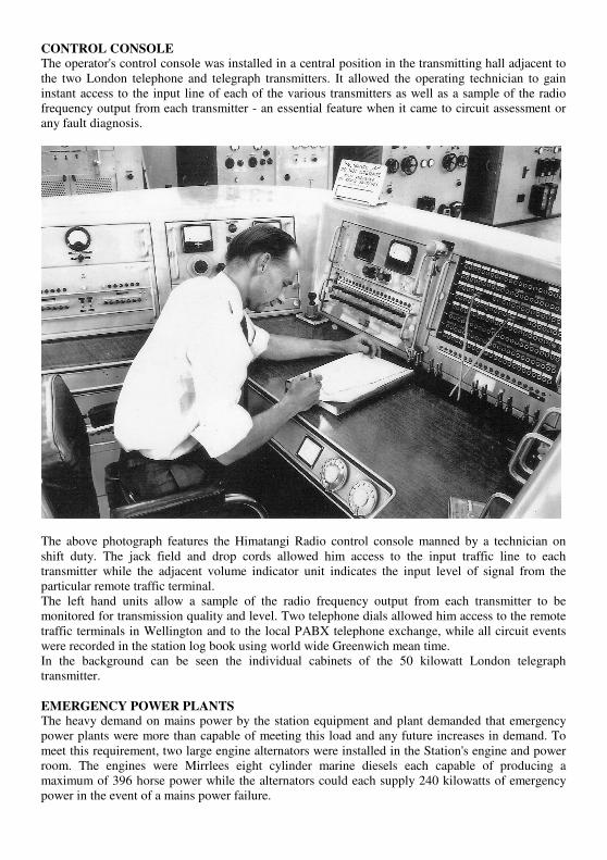
CONTROL CONSOLE
The operator's control console was installed in a central position in the transmitting hall adjacent to
the two London telephone and telegraph transmitters. It allowed the operating technician to gain
instant access to the input line of each of the various transmitters as well as a sample of the radio
frequency output from each transmitter - an essential feature when it came to circuit assessment or
any fault diagnosis.
The above photograph features the Himatangi Radio control console manned by a technician on
shift duty. The jack field and drop cords allowed him access to the input traffic line to each
transmitter while the adjacent volume indicator unit indicates the input level of signal from the
particular remote traffic terminal.
The left hand units allow a sample of the radio frequency output from each transmitter to be
monitored for transmission quality and level. Two telephone dials allowed him access to the remote
traffic terminals in Wellington and to the local PABX telephone exchange, while all circuit events
were recorded in the station log book using world wide Greenwich mean time.
In the background can be seen the individual cabinets of the 50 kilowatt London telegraph
transmitter.
EMERGENCY POWER PLANTS
The heavy demand on mains power by the station equipment and plant demanded that emergency
power plants were more than capable of meeting this load and any future increases in demand. To
meet this requirement, two large engine alternators were installed in the Station's engine and power
room. The engines were Mirrlees eight cylinder marine diesels each capable of producing a
maximum of 396 horse power while the alternators could each supply 240 kilowatts of emergency
power in the event of a mains power failure.
To ensure that the station equipment was free of any vibrations from these large engines when
operating at 500 resolutions per minute, considerable precautions were taken in their initial
installation. Each engine alternator unit was mounted on a large concrete block which in turn was
mounted on a series of massive leaf springs installed below floor level. The resultant vibration free
operation of the two Mirrlees engines was no doubt further assisted by the fact that the flywheel
fitted to each engine was of substantial proportions.
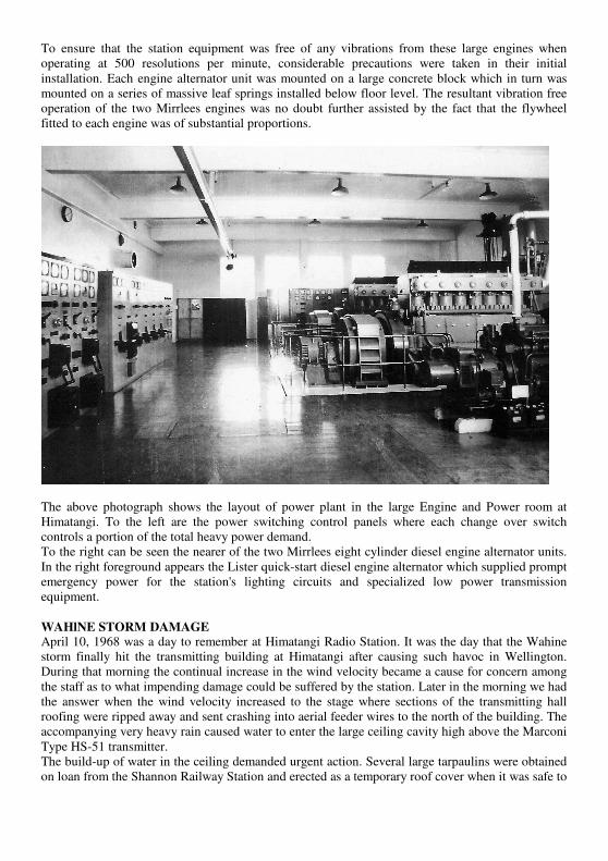
The above photograph shows the layout of power plant in the large Engine and Power room at
Himatangi. To the left are the power switching control panels where each change over switch
controls a portion of the total heavy power demand.
To the right can be seen the nearer of the two Mirrlees eight cylinder diesel engine alternator units.
In the right foreground appears the Lister quick-start diesel engine alternator which supplied prompt
emergency power for the station's lighting circuits and specialized low power transmission
equipment.
WAHlNE STORM DAMAGE
April 10, 1968 was a day to remember at Himatangi Radio Station. It was the day that the Wahine
storm finally hit the transmitting building at Himatangi after causing such havoc in Wellington.
During that morning the continual increase in the wind velocity became a cause for concern among
the staff as to what impending damage could be suffered by the station. Later in the morning we had
the answer when the wind velocity increased to the stage where sections of the transmitting hall
roofing were ripped away and sent crashing into aerial feeder wires to the north of the building. The
accompanying very heavy rain caused water to enter the large ceiling cavity high above the Marconi
Type HS-51 transmitter.
The build-up of water in the ceiling demanded urgent action. Several large tarpaulins were obtained
on loan from the Shannon Railway Station and erected as a temporary roof cover when it was safe to

do so. The volume of water trapped in the ceiling was eventually drained out via deliberately
punctured holes into containers clear of any transmitter equipment.
Following repairs to the broken aerial feeder lines, the affected services were restored to their
normal transmitting equipment and a private contractor was engaged to replace the damaged
sections of the station roofing.
OFFICIAL OPENING
Himatangi Radio Station was officially opened at a ceremony held at the station on November 9th,
1953 at 2 pm before on attendance of at least 500 people. Chairman on that occasion was Mr P.N.
Cryer, the Director General of the New Zealand Post Office. Following his introductory remarks the
official opening was performed by the then New Zealand Postmaster General the Hon. W.J.
Broadfoot followed by a recording of the first radio-telephone conversation between Mr Broadfoot
and the Right Hon. Earl de la Warr, Postmaster General, United Kingdom. Official guests also
included Mr J. Malone, Chairman Overseas Telecommunications Commission (Australia), Sir
Mathew Oram, Speaker of the House of Representatives and Mr. P.H.N. Freeth, Chairman of the
New Zealand Press Association.
THE QUEEN'S MESSAGE
An important early assignment for the new Himatangi Radio Station was to be the relaying of the
Queen's Christmas Day message to the Commonwealth during her visit to New Zealand in 1953.
Queen Elizabeth was to broadcast from Auckland and be transmitted directly from Himatangi to
London then re-transmitted on to countries throughout the Commonwealth.
This international radio-telephone commitment was successfully completed and provided tangible
proof of the ability of Himatangi Radio Station to provide a commercial quality radio-telephone
transmission to the United Kingdom.
In her Christmas Day message the Queen made mention of the grievous rail disaster which had
occurred at Tangiwai on that Christmas Eve. The loss of life from this tragedy was finally verified
as 151.
NEW TECHNOLOGY
A crucial event in the role of Himatangi Radio Transmitting Station was the opening of the new
Satellite Earth Station at Warkworth, New Zealand in 1971. Working via the INTELSAT system of
satellites Warkworth, New Zealand was in a position in 1987 to take over the major international
radio circuits operating via Himatangi Radio Station. Shorter overseas transmissions from
Himatangi to the Pacific Islands, Chatham Islands, Scott Base, Pitcairn and some shipping services
were later transferred to either satellite operation, the New Zealand Navy station at Waiouru or
Broadcast Communications Ltd.
END OF AN ERA
Being overtaken by new technology, the days of Himatangi Radio Transmitting Station came to an
end operationally on the 30th September, 1993. All inside and outside plant and equipment was
eventually dismantled and disposed of, including the two large Mirrlees diesel engine alternator
units; one going to the Tokomaru Steam Museum and the other to Manawatu Hydraulics Ltd,
Palmerston North.
The 800 acre block of station farm property, including the station buildings was sold to a local
farmer to add to his existing holdings. The staff houses and single staff hostel were leased by
Telecom to a local businessman for use as backpackers and rental housing accommodation.
The days of Himatangi Radio Transmitting Station were over.


