
OBJECT ORIENTED SOFTWARE ENGINEERING FOR DESIGNING AN AERIAL SURVEY LIDAR SIMULATOR
Rakesh Kumar Mishra, Bharat Lohani
Geoinformatics division, Indian Institute of Technology Kanpur, Kanpur 208016, INDIA – [email protected]
KEY WORDS: Object-oriented, Software engineering, LiDAR, Modelling of sensor, Research and education tool ABSTRACT: This paper describes the object oriented design methods used to develop a software system to simulate the functioning of an aerial survey LiDAR instrument. Object-oriented design is a design strategy where system designers think in terms of ‘things’ instead of operations or functions. The goal of this paper is to model functions of an actual LiDAR instrument by using object oriented software engineering approach so that the developed software could be maintainable, reliable and scalable. The simulator is conceived with three components, namely terrain component, sensor component and trajectory component. Each component has been divided into their sub modules and designed independently. The terrain component deals with generation of bare terrain and objects on top of the terrain. The sensor component deals with design of commercially available sensors or a generic sensor. And the trajectory component deals with modelling of platform parameters, viz., velocity, roll, pitch, yaw and accelerations. Numerical methods are used to solve complex problems for generating LiDAR data from simulated terrain and flights. LiDAR data files are generally very large. Considering this, special data structures and file formats have been designed to improve the performance and to solve the memory problems. This user friendly GUI based simulator, developed in JAVA programming language, is an ideal tool for research and education.
1. INTRODUCTION
1.1 Background
The last decade has seen manifold growth in the use of aerial survey LiDAR (Light Detection and Ranging) technology. Due to the main advantage of measuring topography through highly dense and accurate data points which are captured at high speed, the LiDAR technology has found several interesting applications (Lohani, 2001; Queija, et al., 2005). 1.2 Object-oriented software engineering
Software engineering has traditionally been an expensive and time-intensive process. Object-oriented analysis and design is the principal industry-proven methodology that answers the call for a more cost-effective, faster way to develop software and systems. Object-oriented technology cuts development time and overhead, leading to faster time to market and significant competitive advantage, enabling software engineers to produce more flexible and easily maintainable applications. 1.3 Characteristics of LiDAR simulator
A LiDAR simulator is aimed at faithfully emulating the LiDAR data capture process with the use of mathematical models under a computational environment. Basically, data generated by simulator should exhibit all characteristics of data acquired by an actual LiDAR sensor. Literature reveals that only a few attempts have been made by researchers to develop simulator for LiDAR instrument. These efforts are limited in their scope as either these consider the effect of only single parameter on one kind of object (Holmgren et al., 2003) or inaccurate scanning pattern (Beinat and Crosilla, 2002). Another attempt is made (Kukko and Hyyppa, 2007) using MATLAB however the simulator has limitations as it is designed only for test purpose and does not offer flexibility and completeness. More focused and comprehensive efforts have been made to simulate the return waveform from a footprint (Sun and Ranson, 2000; Tulldahl and Steinvall, 1999).
1.4 Requirement of LiDAR simulator software
Considering the significance of LiDAR technology there is a need to introduce LiDAR technology to students at undergraduate and postgraduate level. LiDAR instrument and data are costly. Collecting LiDAR data with varied specifications, as are desired for classroom teaching and laboratory exercises, may not be viable considering the cost and availability of instrument. A simulator can generate various kinds of data, as and when desired, at minimal or no cost. This data could be very useful for conducting laboratory exercises. User control over the entire data generation process in simulator can also help students in understanding the functioning and limitation of LiDAR instrument. Further, error sources and their effect on LiDAR data can be understood. In any laboratory exercise availability of ground truth is fundamental. While it may be difficult and expensive to collect ground truth in case of actual LiDAR data, for simulated data the ground truth is readily and accurately available. In addition to education, there are several other applications where data generated by simulator can be employed. In particular, for testing the information extraction algorithms for their performance over a wide variety of data is conveniently possible with simulated data. It can also be used for LiDAR flight planning.
2. BENCHMARK FOR LIDAR SIMULATOR
Considering the aforesaid applications the following benchmarks are set for the simulator:
Simulator should employ a user-friendly GUI (Graphical User Interface.) Simulator should be easily extendable and maintainable. Simulator should be designed for wider distribution over various computational platforms.
3
IpTsnftci
Eaiomd 3
TMaouges
The simulsystem whifriendly muIt should widely avaiThe simulasensor paraof introducLiDAR. Simulator slike surfaceThe outputLiDAR for
3.
3.1 Software c
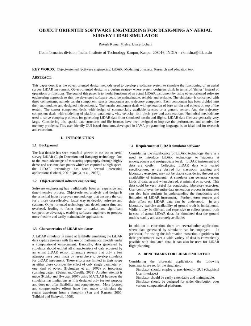
In view of programming (OThis technologysoftware. OOP number of entifunctions arounthe code reusabicomponents in ain Figure 1.
Figure 1. Basi
Each componenaccordingly. Eaintegration geneof these componmathematical mdevelopment of
3.2 Terrain co
Terrain componMathematical suare designed to objects. Each musing GUI. The generation. Furteach module toshown in Figure
Mathemati
Terrain componen
ator should coich can explain ultimedia techniqsimulate a genilable sensors inator should facilameters as in accing errors in
should facilitate es. t data should brmats.
SOFTWARE
components
the aforesaid OOP) has been uy offers a new a
allows decomities called objed these objects.ility. The simuaddition to inpu
ic components a
nt is divided intoach module takeserates LiDAR danents is realised
models. The folthe present vers
omponent
nent (Figure 2) isurface, Raster a
simulate bare emodule has facil
marked area bether, the user haso create the terre 3.
Figure 2. Terr
Terrain com
ical surface
INP
Sencompnt
OUT
me along withconcepts of LiD
ques. neric LiDAR sen market. litate selection o
ctual case along various compon
data generation
be available in
DEVELOPME
requirements used for developiand powerful m
mposition of a ects and then A major advan
ulator is composut and output mo
and their integrat their sub modus input from the ata as desired byd by developingllowing paragrapion of software.
s combination ond fractal. Thesearth surface anlity to mark arecomes availables option to chanrain of his choi
rain component
mponent
Raster F
PUT
nsor ponent
Tco
TPUT
h a help/tutoriaDAR using user
ensor and some
of trajectory andwith the facility
nent systems o
for actual earth
commonly used
ENT
object-orienteding the simulato
model for writingproblem into abuilds data andntage of OOP ied of three basicodules as shown
tion in software
ules and designeduser, while thei
y the user. Eachg algorithms andphs describe the
of three modulesse three modulend above groundea of interest bye for LiDAR datage parameters oice. The GUI i
Fractal
Trajectory omponent
al r-
e
d y f
h-
d
d r. g a d s c n
d ir h d e
s, s d y a f s
3.2.1 MIn this, tequations, selection oare AX+BYZ=A [sinZ=A [sin
3.2.2 RIn this, a different oGUI permobjects onobjects. Thfile formaaddition, itLiDAR da 3.2.3 FrHere, a nalgorithmschosen aregenerated 3.3 Senso
Two comma generic modules. Dof the abofor LiDARfiring freqparametersspecificatirange of (Lohani a
Mathematical surerrain is modewhich yield ear
of these surfaces
Y+CZ+D=0 n(X/B) - sin (n(X/B) – cos
Figure 3. GU
Raster terrain using th
objects over the mits to choose thn it. Further, it phe generated rasat to improve tt is possible to i
ata can be genera
ractal natural-looking ts. This moduleea by using GUby varying inpu
or component
mercially availabsensor (Figur
Developed GUI ve sensors and sR data generatio
quency, type of s is constrainedons. The generparameters. Fo
and Mishra,2007
Figure 4
Senso
Generic senso
face eled by using rth like surfacess and their param
XY / C)] (XY / C)]
UI for terrain com
he above mathesurfaces are rast
he surface type permits to drag ster data is savedthe performanceimport an existinated.
terrain is genere generates ranUI. Different typut parameters.
ble sensors (ALre 4) are desig(Figure 5) faciliset their parameon, viz., scan ascanning (Figur
d in commerciaric sensor perm
or algorithmic d).
4. Sensor compo
r component
r ALTM
mathematical s. The software pmeters. A few o
(1)
mponent.
ematical surfaceterized. The devand different tyand resize the
d in specially dee of the softwang raster file for
rated by using ndom fractal fopes of fractals c
LTM and ALS 5gned as indepitates selection o
eters which are dangle, scan freqre 6) etc. The ral sensors as pe
mits selection odetail please re
nent
M ALS 50
surface permits f these
)
es and veloped ypes of placed
esigned are. In which
fractal for the can be
0) and endent of any desired quency, ange of r their
of any efer to
3
Taeasogaa
3As(sma
Fi
Figure
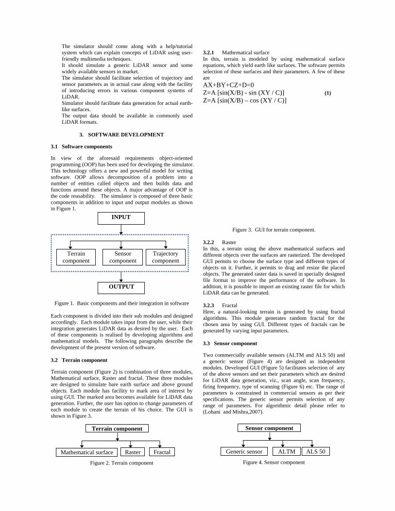
3.4 Trajectory
This componenattitude. Locatioeach instance oacceleration. Ansemi random (coof altitude angenerates trajectat each instanceand Mishra-2007
3.4.1 LocatioA trajectory (resingle flight) is (point of originsystem at each modules, velocacceleration mo
T
Lo
Acceleration
gure 5. GUI for
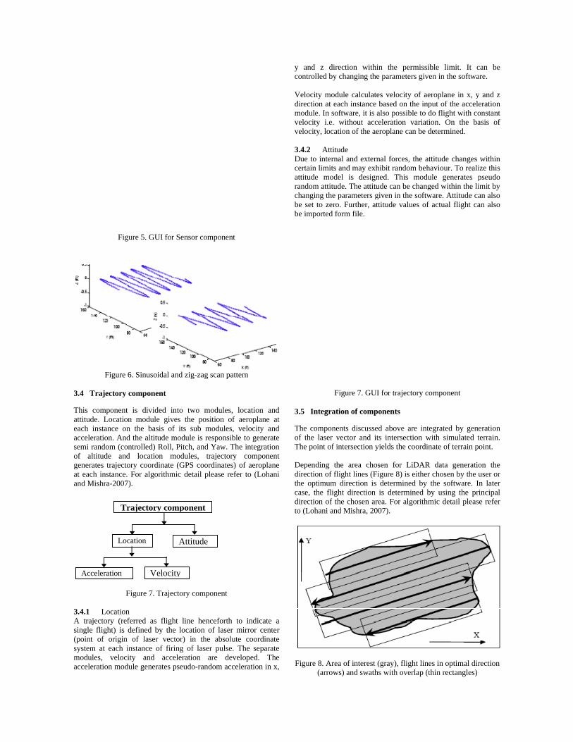
e 6. Sinusoidal an
y component
nt is divided inon module giveon the basis of nd the altitude montrolled) Roll, nd location mtory coordinate
e. For algorithm7).
Figure 7. Trajec
on eferred as fligh
defined by then of laser vectinstance of firi
city and accedule generates p
Trajectory com
ocation
Velocit
Sensor compone
nd zig-zag scan
nto two modulees the position f its sub modulemodule is respon
Pitch, and Yawmodules, traject
(GPS coordinatmic detail please
ctory component
ht line hencefore location of lastor) in the absoing of laser pulseleration are dpseudo-random a
mponent
Attitude
ty
ent
pattern
es, location andof aeroplane a
es, velocity andnsible to generate. The integrationtory componentes) of aeroplanerefer to (Lohan
t
rth to indicate aser mirror centeolute coordinatese. The separatedeveloped. Theacceleration in x
d at d e n
nt e
ni
a r e e e
x,
y and z controlled Velocity mdirection amodule. Invelocity ivelocity, lo
3.4.2 ADue to intcertain limattitude mrandom attchanging tbe set to zbe importe
3.5 Integ
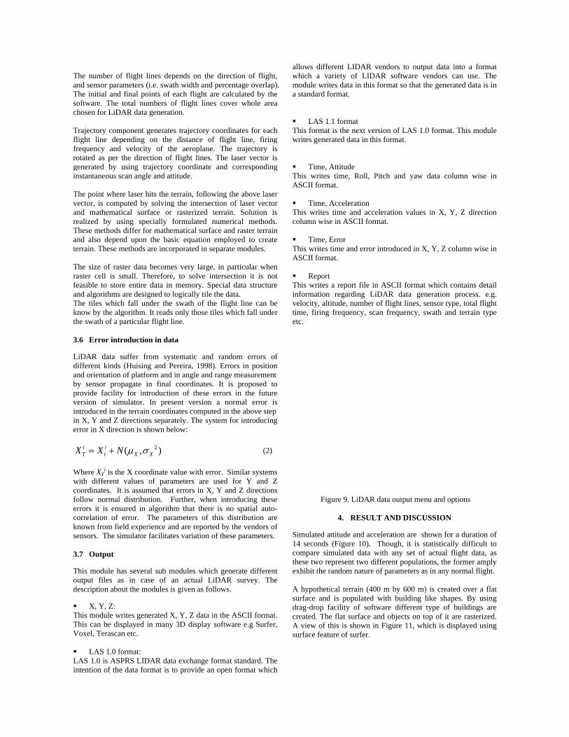
The compof the laseThe point Dependingdirection othe optimucase, the fdirection oto (Lohani
Figure 8. A(arr
direction withiby changing the
module calculateat each instance n software, it is a.e. without accocation of the ae
Attitude ternal and extern
mits and may exhmodel is designtitude. The attituthe parameters gzero. Further, ated form file.
Figure 7. GUI
gration of comp
ponents discusseer vector and itof intersection y
g the area choof flight lines (Fium direction is flight direction of the chosen ari and Mishra, 20
Area of interest (rows) and swath
in the permissie parameters giv
es velocity of aebased on the inp
also possible to deleration variat
eroplane can be d
nal forces, the ahibit random behned. This moduude can be changgiven in the softwttitude values of
I for trajectory c
onents
ed above are intts intersection wyields the coordin
sen for LiDARigure 8) is eitherdetermined by is determined b
rea. For algorithm07).
(gray), flight lin
hs with overlap (t
ible limit. It cven in the softwa
eroplane in x, yput of the acceledo flight with cotion. On the badetermined.
attitude changes haviour. To realiule generates pged within the liware. Attitude caf actual flight ca
omponent
tegrated by genewith simulated tnate of terrain p
R data generatior chosen by the uthe software. In
by using the primic detail pleas
es in optimal dirthin rectangles)
can be are.
y and z eration onstant asis of
within ize this pseudo imit by an also an also
eration terrain. oint.
on the user or n later incipal e refer
rection
TaTsc Tffrgi TvarTat TrfaTkt 3
Ldabpviie
Wwcfecks 3
Tod
TTV
Li
The number of and sensor paramThe initial and software. The tchosen for LiDA
Trajectory compflight line depefrequency and rotated as per thgenerated by uinstantaneous sc
The point wherevector, is compuand mathematicrealized by usiThese methods dand also dependterrain. These m
The size of rastraster cell is smfeasible to storeand algorithms aThe tiles whichknow by the algthe swath of a pa
3.6 Error intro
LiDAR data sudifferent kinds and orientation oby sensor propprovide facility version of simintroduced in thein X, Y and Z derror in X direct
i iT tX X N= +
Where XTi is the
with different vcoordinates. It follow normal errors it is ensucorrelation of eknown from fielsensors. The sim
3.7 Output
This module haoutput files asdescription abou
X, Y, Z: This module wrThis can be dispVoxel, Terascan
LAS 1.0 foLAS 1.0 is ASPintention of the
flight lines depmeters (i.e. swatfinal points of etotal numbers oAR data generati
ponent generatesending on the velocity of th
he direction of using trajectory can angle and att
e laser hits the teuted by solvingcal surface or ing specially fdiffer for mathemd upon the bas
methods are incor
ter data becomemall. Therefore,e entire data in are designed to lh fall under the gorithm. It reads articular flight li
oduction in dat
uffer from syst(Huising and Peof platform and pagate in final
for introductiomulator. In pres
e terrain coordindirections separation is shown bel
2( , )X XN μ σ
e X coordinate vvalues of paramis assumed that distribution. F
ured in algorithmerror. The parald experience anmulator facilitate
as several sub m in case of a
ut the modules is
ites generated Xplayed in many n etc.
ormat: PRS LIDAR data
data format is t
pends on the dirth width and pereach flight are cof flight lines coion.
s trajectory coordistance of fli
e aeroplane. Tflight lines. Thcoordinate and
titude.
errain, followingg the intersection
rasterized terraformulated nummatical surface aic equation emprporated in separ
s very large, in , to solve intersmemory. Speci
logically tile the swath of the flonly those tiles
ine.
ta
tematic and raereira, 1998). Ein angle and rancoordinates. It
on of these erroent version a
nates computed iately. The systemlow:
alue with error. meters are usederrors in X, Y
Further, when inm that there is ameters of this
nd are reported bes variation of th
modules which gan actual LiDAs given as follow
X, Y, Z data in th3D display soft
a exchange formo provide an op
rection of flightrcentage overlapcalculated by theover whole area
rdinates for eachight line, firing
The trajectory ihe laser vector id corresponding
g the above lasen of laser vectoain. Solution i
merical methodsand raster terrainployed to createrate modules.
particular whensection it is noial data structuredata.
light line can bewhich fall unde
andom errors oErrors in positionnge measurement
is proposed toors in the futurenormal error iin the above step
m for introducing
(2)
Similar systemd for Y and Zand Z directionntroducing theseno spatial autodistribution are
by the vendors ohese parameters.
generate differenAR survey. Thews.
he ASCII formattware e.g Surfer
mat standard. Thepen format which
t, ). e a
h g s s g
r r s s. n e
n ot e
e r
of n t o e s
p g
s Z s e -e f
nt e
t. r,
e h
allows difwhich a vmodule wra standard LAS
This formawrites gen Time
This writeASCII form Time
This writecolumn wi Time
This writeASCII form Repo
This writeinformatiovelocity, atime, firinetc.
F
Simulated 14 secondcompare sthese two exhibit the A hypothesurface andrag-drop created. ThA view ofsurface fea
fferent LIDAR vvariety of LIDrites data in this format.
1.1 format at is the next ver
nerated data in th
, Attitude es time, Roll, Pmat.
, Acceleration es time and accise in ASCII form
, Error s time and errormat.
rt es a report file inon regarding Lialtitude, number ng frequency, sc
igure 9. LiDAR
4. RESUL
attitude and accds (Figure 10). simulated data wrepresent two di
e random nature
etical terrain (40nd is populated
facility of softhe flat surface a
f this is shown inature of surfer.
vendors to outpAR software vformat so that t
rsion of LAS 1.his format.
Pitch and yaw
eleration valuesmat.
r introduced in X
n ASCII formatiDAR data genof flight lines, s
can frequency, s
data output men
LT AND DISCU
celeration are shThough, it is s
with any set of ifferent populatiof parameters as
00 m by 600 m)with building l
tware different and objects on ton Figure 11, wh
put data into a vendors can usethe generated dat
0 format. This m
data column w
s in X, Y, Z dir
X, Y, Z column w
t which containsneration processensor type, totalswath and terrai
nu and options
USSION
hown for a durastatistically diffif actual flight dions, the formers in any normal
) is created overlike shapes. Bytype of buildinop of it are rast
hich is displayed
format e. The ta is in
module
wise in
rection
wise in
s detail s. e.g. l flight in type
tion of cult to ata, as amply flight.
r a flat y using ngs are erized.
d using

LFK3TpFa
Figure 10. A
Figure
Lidar data are Flight velocity: KHz; Scan frequ3; Overlap 10Terrascan softwpresented for thFigure 13. To saltitude value is
ttitude (top) and
11. Surfer surfac
generated for th60 m/s;Altitud
uency: 48Hz; Sc%. Resulting L
ware and displayhe sake of spacshow the effecttaken.
d acceleration (bo
ce of the created
his terrain with de: 190m; Firingcan angle 500; NLiDAR data ayed. Only few ce as shown int of multiple fli
ottom) values
d terrain.
the parametersg frequency: 20o. of flight lines
are imported inviews are being
n Figure 12 andight lines, smal
s: 0 s: n g d ll
Profile viewhich is hwhere datshadow is not capturmarked bycan be undblack areaserves as height, wh
Figure 12.
Figure 13.
Figure 14 n
ew of the generahaving three flighta are capturedalso evident. N
red) are shadowy white oval is nderstood in profa is not being coan example of p
hich can be unde
. Lidar data displ
Lidar data displThe profile is sh swaths. The bu
. Effect of high no attitude varia
ted LiDAR dataht lines. This sh
d, while the intNot all black arews. For examplenot fully capturefile (also markedovered by eitherpoor choice of rstood by simula
lay in Terrascan
lay in Terrascanhown along withuilding within ov
(a)
(b) attitude on comp
ation. (b) with hig
a is shown in Fighows various buiterplay of objecas (i.e. where da
e, the roof of bued. The reason fd by white ovalr flight line. Thscan angle and ator.
n for the above su
- profile view. h the flight lines val is not measur
plex building. (agh attitude varia
gure 13 ildings ct and ata are uilding for this .). The
his also flying
urface.
and red.
a) with ation.

T
aasrdlfoTiF
Tissaatuicpfpdeup
The zoomed out14 (a) and (b)) oattitude variationattitude effects ospread of point crespect to flight data points are aline, while no daflight lines are soverlap of two fThe generated rain surfer. The LiFigure 16)
Figur
Figure 16. Lid
The present versinterface so thasimulates the psensor as well according to hiactual LIDAR. Dterrain by settinguseful to generais also useful icapture process parameters and flight planningparameters, fligdeveloped usinextended furtheused to developprogramming a
t view of a compof the same placens. These figureon the point cloucloud depends online and parame
available on the vata points are caphow by arrow. T
flight lines. aster for a fractaiDAR data is gen
re 15. Fractal sur
dar data of fracta
5. CONC
sion of software at the user can process of LiDAas the user hass choice whichDifferent data seg the different p
ate LiDAR data fn a classroom and understanditheir errors. Fur. Before actua
ght direction etcng object-oriente
r very easily. JAp the software s well as havin
plex building (she with no attituds give understan
ud. This also shon the location of
eters chosen for svertical wall facptured on the othThe figure also s
al surface is shownerated for this f
rface display in s
al surface display
CLUSION
offers a user frieuse this softwa
AR data collects freedom to seth is not possibleets can be generaparameters. The for research to tefor demonstrati
ing the effect of rther, it can be ual flight the ec can be seen. ed methodologyAVA programmas it supports
ng excellent GU
hown in Figure e and with high
nding that how ows that the f the object with sensor. LiDAR ing the flight her wall. The shows the
wn in Figure 15 fractal (shown in
surfer.
y in Terrascan
endly GUI basedare with ease. Ition for LIDARt the parametere in the case oated for the samesimulator can beest algorithms. Iing LiDAR dataflight and sensouseful in LiDAReffect of sensoThe software iy so it can be
ming language iobject oriented
UI features. The
n
d It R s f e e It a r
R r s e s d e
platform inmultiple op The preseincorporatIMU dataconcepts oincorporatmultiple re ReferenceBeinat, Astochastic images, Insensing an Marciniakencyclopedfor Softwa Holmgreneffect of liand canop29(5), pp. Husing, Eestimates systems fPhotogram Lohani, BlaboratoryPhotogramLaser ScaSeptember Kukko, Asystem anameasuremand SiviLa Lohani, B.AltimetricArchives ofInformatio Lohani, B.data collecconference Queija, V.U.S. geolopp. 5-9. Sun, G. anforest canosensing, 38
5.1 Ackn
This work
ndependency ofperating systems
ent version ofte more faithfulna collection anof separation of ting atmospherieturns, etc.
es A., and Crosilla
model for opnternational Arcnd spatial inform
k, J.J., 2001, Prodia of software are Research, Un
, J., Nilsson, M.idar scanning anpy closure. Can623-632.
E. J. and Pereiraof laser data
for topographicmmetry & Remot
B., Mishra, R. Ky: LiDAR simmmetry , and Ranning 2007 anr 12-14.
A. and Hyypa Jalysis and algor
ments, ISPRS Waser 2007, Espoo
., Reddy, P., and LiDAR Simula
of the Photogramon Science, XXX
., 2001, Airbornction: Issues ande MAPINDIA-20
R., Stoker, J. Mogical survey app
nd Ranson, K. J.,opies, IEEE tran8(6), pp. 2617-2
nowledgements
is supported un
f JAVA made ths.
f simulator is ness by introducnd their integra
GPS antenna, laic effects and
a, F., 2002. A ptimal registratichives of photog
mation sciences,
ocess models in engineering. W
niversity of Calif
, and Olsson, H.ngle for estimationadian Journal
a, L. M., 1998,acquired by vac applications, te Sensing, 53(5)
K., 2007, Genermulator, InternRemote Sensin
nd SilviLaser 2
., 2007, Laser rithm developme
Workshop on LAo, September 12
d Mishra, R.K., 2tor: An educatio
mmetry, Remote SXVI(6), Tokyo, J
e altimetric LiDd application., Pr001, 7-9 Februar
M., and Kosovichplications of LiD
, 2000. Modelingns. On geoscienc2626.
der RESPOND p
his software to r
being modificing separate GPation; by introdaser head and IN
d by facilitatin
generalized faon of LIDAR grammetry an r34(3/B), pp. 36-
software engineWalt Scacchi, Infornia, Irvine.
., 2003. Simulation of mean tree l of Remote Se
, Errors and acarious laser sca
ISPRS Journ), pp. 245-261.
rating LiDAR dnational Archivng XXXVI(3)W2007, Espoo, Fi
scanner simulatent: A case withASER Scanning-14, 2007, Finla
2006, Airborne on tool, InternatiSensing and SpaJapan.
AR for topograproc. of Internatiory 2001, New De
h, J. J., 2005, RecDAR, PE&RS, 7
g Lidar returns fces and remote
programme of IS
run on
ied to PS and ducing NS; by ng for
actored range
remote -39.
eering, nstitute
ing the height
ensing,
curacy anning nal of
data in ve of
W52 of inland,
tor for h forest g 2007 and.
ional atial
phic onal elhi.
cent 1(1),
from
SRO.


