

0093-9994 (c) 2013 IEEE. Personal use is permitted, but republication/redistribution requires IEEE permission. Seehttp://www.ieee.org/publications_standards/publications/rights/index.html for more information.
This article has been accepted for publication in a future issue of this journal, but has not been fully edited. Content may change prior to final publication. Citation information: DOI10.1109/TIA.2013.2296626, IEEE Transactions on Industry Applications
On Radio-Frequency Based Detection of High-Frequency Circulating
Bearing Current Flow
Annette Muetze Ville Niskanen Jero Ahola
Graz University of Technology Lappeenranta University Lappeenranta University
8010 Graz, Austria 53850 Lappeenranta, Finland 53850 Lappeenranta, Finland
[email protected] [email protected] [email protected]
Abstract—The possibility of bearing damage caused byinverter-induced bearing currents in modern variable-speed drivesystems has been well recognised today. Further research isneeded to develop appropriate non-intrusive methods for detec-tion and monitoring of such currents. A radio-frequency basednon-destructive method has been applied to detect dischargebearing currents. The method is understood to work on theenergy that is radiated in the electric field during the bearingdischarge event. We show that the method is also applicable tohigh-frequency circulating bearing currents that have so far beenassociated with ohmic bearing characteristics and no dischargesoccurring. The analysis and understanding of the applicabilityof the method to detect such currents also contributes to furtherunderstanding of the electric characteristics of the bearing,notably the moment the current conduction begins.
NOMENCLATURE
CM Common mode.
DE Drive-end.
HF High frequency.
HV High voltage.
LV Low voltage.
MV Medium voltage.
NDE Nondrive-end.
PD Partial discharge.
PE Protective earth.
RF Radio frequency.
I. MOTIVATION
A. Bearing Current Research, Monitoring, and Diagnosis
The possibility of bearing damage caused by inverter-
induced bearing currents in modern variable-speed drive sys-
tems has been well recognised today. Different authors have
described the cause-and-effect chains, allowing the selection
of appropriate mitigation techniques (e.g. [1]–[11]). Notably,
distinction between (a) discharge bearing currents, that are
directly related to the high-frequency (HF) common-mode
(CM) voltage, and (b) HF circulating current that are caused
through inductive coupling by the HF stator CM current and
that are thus more prevalent with machines with larger frame
sizes, is important.
The mitigation techniques are frequently applied as preven-
tative measures to avoid bearing failure. Common approaches
include different types of filters and chokes, inverter modu-
lation schemes that minimize the CM voltage, electrostatic
shielding, slip and shaft grounding rings, and insulated or
hybrid bearings (e.g. [6]–[17]). These techniques come with
additional cost, and a trade-off has to be made between the
per-default application of a mitigation technique and further
analysis of the bearing currents occurring within a system. The
choice will depend on the overall system, its configuration and
cost, and the application.
It is desirable to further reduce the additional cost and
risk associated with such parasitic currents. Development and
research on bearing current monitoring and diagnosis as well
as on the current-conduction and damage mechanisms within
the bearing will all contribute to this aim.
Today, mostly intrusive techniques are applied to measure
such bearing currents: Commonly, an electrically insulating
layer is introduced into the current path. This electrical in-
sulation is then shortened with a small wire, and the current
flow through the wire measured. Such a method is not suitable
for wide-spread cost-effective application in the field. Further-
more, the measurement circuit affects the measured currents.
While models to conclude on the current flow in the respective
system before modification are available (e.g. [18]), they
only reflect the existing understanding and thus have limited
applicability to enhance the understanding of the current flow
mechanism. Thus, non-destructive methods for the detection
and monitoring of inverter-induced bearing currents may be
considered a great asset towards an even better understanding
of such current flow and possible damage.
B. Non-intrusive Detection of Inverter-Induced Bearing Cur-
rents Under all Operating Conditions
A radio-frequency (RF) based non-intrusive method to de-
tect discharge bearing currents has been presented and used
to evaluate and further understand the occurrence of discharge
currents [19]–[21]. The method is based on the understanding
of an electric machine as a spark gap transmitter with some
of the energy stored within the bearing and machine (notably
air gap) before the discharge being emitted as an RF signal.
In contrast to these discharges occurring with discharge
bearing currents, the bearings have so far been understood
to have ohmic properties in the case of HF circulating bearing
currents. Based on this understanding, such currents can
thus not be detected with an RF based method that detects
the electric field in the frequency range radiated from any
discharge, because of the lack of occurrence of a discharge
and subsequent release of energy that can be radiated outside
of the bearing. Note that this possibility of detection is not
related to the maximum amplitude of the bearing current. (HF
0093-9994 (c) 2013 IEEE. Personal use is permitted, but republication/redistribution requires IEEE permission. Seehttp://www.ieee.org/publications_standards/publications/rights/index.html for more information.
This article has been accepted for publication in a future issue of this journal, but has not been fully edited. Content may change prior to final publication. Citation information: DOI10.1109/TIA.2013.2296626, IEEE Transactions on Industry Applications
circulating bearing currents generally have larger amplitudes
than discharge currents.)
To the best of the authors’ knowledge, systematic detection
of flow of HF circulating currents with an RF technique
and occurrence of a discharge along with such currents to
be detected have yet to be shown. Such work would both
show that bearing currents under all operating conditions–i.e.
all types of bearing currents–can be detected using an RF
technique and provide further insight into the moment the
current conduction begins.
II. CONTRIBUTION AND ORGANIZATION OF PAPER
We show that HF circulating bearing currents, too, can
be detected using an RF based non-intrusive method. This
is in contrast to the common understanding of purely ohmic
bearing characteristics when such currents flow. It closes the
gap that only some types of bearing currents have been
shown to be detectable through this technique, and allows RF
based detection of inverter-induced bearing currents under all
operating conditions.
Analyzing HF circulating bearing currents further, we
present results from investigations of the switching instant
during which the HF voltage between the two bearings in-
creases, the bearing lubrication film cannot maintain electri-
cally insulating properties, and HF circulating currents start to
flow. The understanding of the applicability of the RF based
method is tightly coupled with further findings on the electric
characteristics of the bearing, notably the moment the current
conduction begins: We have observed instantaneous capacitive
behavior of the bearings already at low rotational speed and
discharges that can be associated with the subsequent flow of
HF circulating currents.
Experimental results with supporting theoretical considera-
tions are given (Sections V–VIII) following short reviews of
the two HF bearing current mechanisms referred to above, the
RF based method, the test setup and an overview of the types
of tests carried out (Sections III and IV).
III. REVIEW OF HF BEARING CURRENTS AND RF BASED
BEARING CURRENT DETECTION
A. Review of HF Bearing Currents
The nonzero HF CM voltage at the output of modern
fast-switching inverters typically changes with every inverter
switching instant and arrives at the motor terminals with a high
dv/dt, where it interacts with the HF machine impedance.
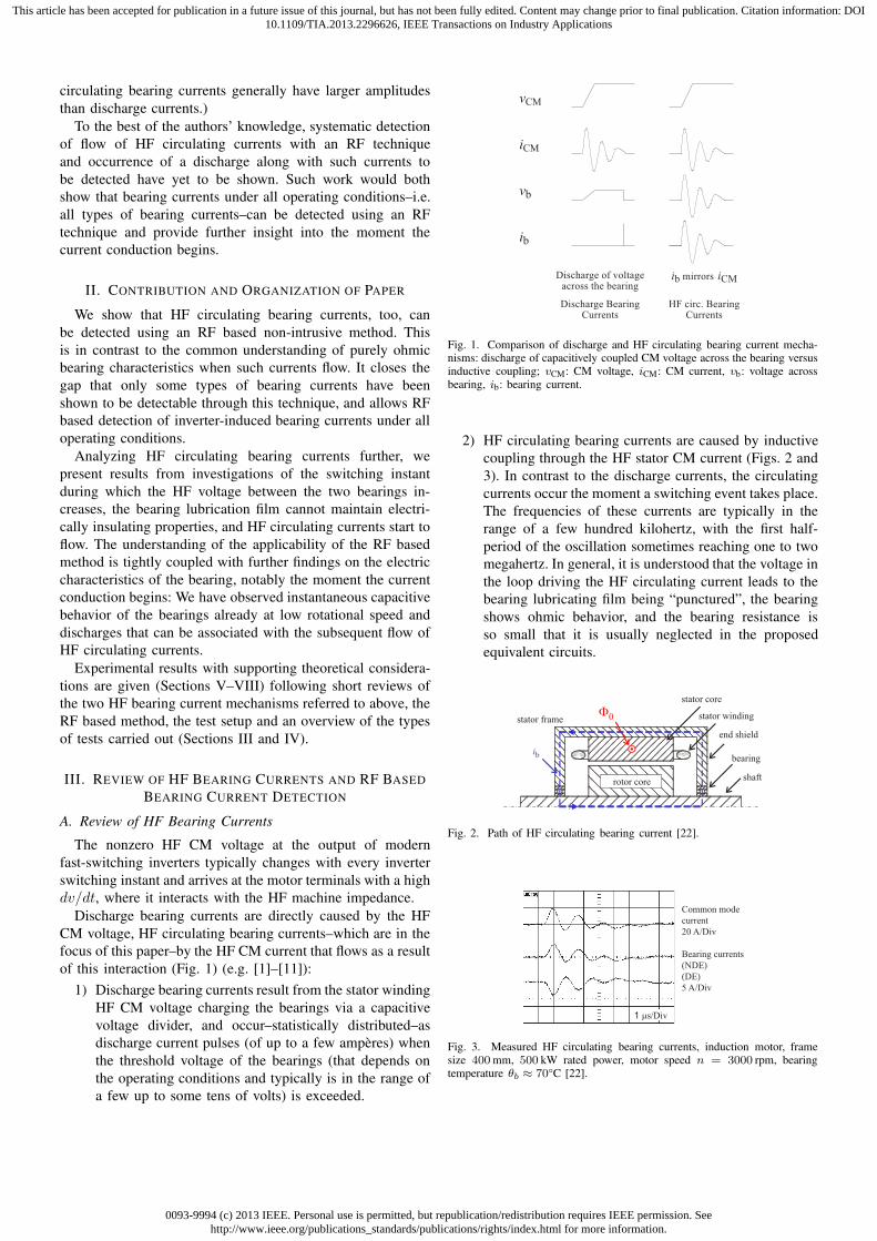
Discharge bearing currents are directly caused by the HF
CM voltage, HF circulating bearing currents–which are in the
focus of this paper–by the HF CM current that flows as a result
of this interaction (Fig. 1) (e.g. [1]–[11]):
1) Discharge bearing currents result from the stator winding
HF CM voltage charging the bearings via a capacitive
voltage divider, and occur–statistically distributed–as
discharge current pulses (of up to a few amperes) when
the threshold voltage of the bearings (that depends on
the operating conditions and typically is in the range of
a few up to some tens of volts) is exceeded.
vCM
iCM
ib
vb
-0.6
3
-0.6
3
-0.6
3
-0.6
3
Discharge of voltageacross the bearing
i ib mirrors CM
Discharge BearingCurrents
HF circ. BearingCurrents
Fig. 1. Comparison of discharge and HF circulating bearing current mecha-nisms: discharge of capacitively coupled CM voltage across the bearing versusinductive coupling; vCM: CM voltage, iCM: CM current, vb: voltage acrossbearing, ib: bearing current.
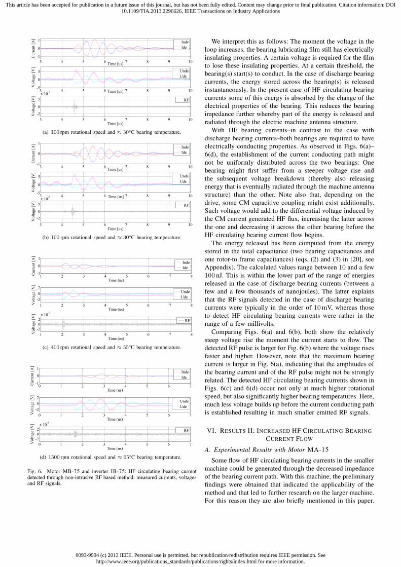
2) HF circulating bearing currents are caused by inductive
coupling through the HF stator CM current (Figs. 2 and
3). In contrast to the discharge currents, the circulating
currents occur the moment a switching event takes place.
The frequencies of these currents are typically in the
range of a few hundred kilohertz, with the first half-
period of the oscillation sometimes reaching one to two
megahertz. In general, it is understood that the voltage in
the loop driving the HF circulating current leads to the
bearing lubricating film being “punctured”, the bearing
shows ohmic behavior, and the bearing resistance is
so small that it is usually neglected in the proposed
equivalent circuits.
stator frame
rotor core
stator winding
stator core
end shield
F0
bearingib
shaft
Fig. 2. Path of HF circulating bearing current [22].
Common mode
current
20 A/Div
Bearing currents
(NDE)
(DE)
5 A/Div
1 ms/Div
Fig. 3. Measured HF circulating bearing currents, induction motor, framesize 400 mm, 500 kW rated power, motor speed n = 3000 rpm, bearingtemperature θb ≈ 70°C [22].
0093-9994 (c) 2013 IEEE. Personal use is permitted, but republication/redistribution requires IEEE permission. Seehttp://www.ieee.org/publications_standards/publications/rights/index.html for more information.
This article has been accepted for publication in a future issue of this journal, but has not been fully edited. Content may change prior to final publication. Citation information: DOI10.1109/TIA.2013.2296626, IEEE Transactions on Industry Applications
B. Review of RF Based Bearing Current Detection
The RF based bearing current detection works similarly to
partial discharge (PD) detection in the insulation of electric
machines. This technique has mainly been developed to de-
termine the quality and state of the insulation and prevent its
premature ageing and failure (for a comprehensive reference,
see [23]). While such techniques have long been established
for form-wound high-voltage (HV) and medium-voltage (MV)
machines, with many devices commercially available (e.g.
[24]–[27]), the increased use of power-electronics converters
has also led to such techniques being developed for detection
of PD in random-wound, low-voltage (LV) windings (e.g.
[28]–[32]). Earlier techniques, notably for the HV and MV
machines were designed for offline application, with the rotor
removed to increase the confidence in the signals, but methods
for online detection have found recent interest, notably in the
context of PD occurring with converter-fed, LV machines.
As for discharge bearing currents, it has been shown that
a fraction of the energy released during the discharge is
radiated outside from the electric motor and can be detected
as RF electric field measurement by appropriate equipment
[19], [20]. In this case, the machine itself operates as a spark
gap transmitter. The characteristics of the RF radiation (e.g.
power, frequency range, radiation pattern) are determined by
the characteristics of the electrical discharge and those of the
electric machine as the transmitting antenna. The frequency
band of the radiation has been determined to be 90−400MHz;
the machine shaft end has been shown to play a key role in
the transmitting characteristics [33], and the radiated power,
even though small, is sufficiently large to be detected.
Any antenna tuned to detect electric fields in the identified
frequency range may be used for this technique, although
an antenna with directivity is highly recommended since it
reduces possible effects of external interferences. A device
based on a similar principle can be obtained on the market,
too, [34]. Note that this device detects RF emissions above a
certain threshold. (Determined at 10mV within our laboratory
tests with a 50Ω load.) In contrast to direct detection with an
RF antenna, it thus does not provide any further insight into
the strength of the emitted RF signal. Note also that many of
the commercially available devices to detect PD in HV and
MV windings are not suitable for the purpose of detecting
bearing currents, since they are operating in a much higher
frequency range of a few gigahertz.
IV. TEST SETUP
A. Drive Systems
Two drives with two different power levels and thus frame
sizes are used for the experiments. Both are 230/400V, 50Hz,
∆-connected, 4-pole induction motors operated by three-phase
400V, 50Hz inverters. The two motors and inverters are
referred to as motors MA-15 and MB-75 as well as inverters
IA-15 and IB-75 respectively. MA-15 is a 160mm frame
size 15 kW, MB-75 a 280mm frame size 75 kW machine. The
two 400V inverters are rated at 14.8A and 82A respectively.
The smaller inverter is operated at 4 kHz (scalar control,
constant switching frequency), the larger one at 3 kHz (direct
torque control, average switching frequency). Both machines
are grounded through the PE conductor of the motor cable
only. Bearing temperatures during operating were in the range
of ≈ (25 . . .65)°C.
In order for the bearing currents to be measured, the
bearings of the example case machines are insulated towards
the housing using an electrically insulating layer of 5mm
thickness applied around the outer bearing race that was short-
ened with a short wire. As discussed above, this technique is
intrusive and will slightly alter the HF current flow when com-
pared to the unmodified case. Using the techniques presented
in [18], this influence is estimated to reduce the amplitudes
of the HF circulating bearing currents by (-10 . . .15)% for
MB-75, and by up to 25% for MA-15.
B. Measurement Equipment
The measurement equipment included an EMCO 93148
antenna that has a bandwidth of 200MHz to 2GHz and that
was placed at approximately one meter distance from the
motor, pointing towards the motor shaft, a Textronix TDS7140
oscilloscope with a bandwidth of 1GHz and a maximum sam-
pling rate of 10GS/s, and an RF bandpass filter Mini-Circuits
BHP100+ with a bandwidth of 90−400MHz (input impedance
set to 50Ω). The HF bearing currents on the nondrive-end
(NDE) and drive-end (DE) sides were measured either with
Tektronix TCP202 50MHz passive (measurements shown in
Figs. 6(a), 6(b), 7(a), 7(b), 9–12) or R&S ZC20 50MHz
active current probes (measurements shown in Figs. 6(c), 6(d),
7(c), 7(d), 8(a)–8(c)); the voltage across the bearings with
a Tektronix P5210 50MHz high voltage differential probe
(Figs. 4 and 5). The HF CM currents were measured using an
R&D EZ-17 100MHz passive current probe. Bearing temper-
atures were measured using an AZ8868 infrared thermometer
between the shaft and the motor end shield.
C. Types of Tests
Four types of tests are carried out:
I. HF circulating bearing current flow “as is”: The electric
machine is operated at low rotational speed and the
HF circulating bearing currents–if flowing–are detected.
(Section V.)
II. Generation of increased HF circulating bearing current
flow: The NDE bearing and its insulation are shortened
to decrease the impedance of the path of the circulat-
ing current. This additional measure decreases the HF
impedance in the path of the HF circulating currents and
the thus the likeliness for these to occur at increased
rotational speed and/or low bearing temperatures. (Sec-
tion VI.)
III. Bearing currents due to rotor ground currents: The NDE
bearing insulation was again left open. The machine
was grounded via the rotor, i.e. the stator grounding
connection eliminated and the rotor connected to ground
with the help of a sleeve made from the tinned copper
braid of the coaxial shield of the supply cable. In
this configuration, any HF CM current would return to

0093-9994 (c) 2013 IEEE. Personal use is permitted, but republication/redistribution requires IEEE permission. Seehttp://www.ieee.org/publications_standards/publications/rights/index.html for more information.
This article has been accepted for publication in a future issue of this journal, but has not been fully edited. Content may change prior to final publication. Citation information: DOI10.1109/TIA.2013.2296626, IEEE Transactions on Industry Applications
Fig. 4. Measurement setup of motor MA-15 (15 kW).
Fig. 5. Measurement setup of motor MB-75 (75 kW).
ground via the rotor grounding connection, thereby pass-
ing the DE bearing current. Since HF circulating bearing
currents are generated through inductive coupling of the
HF CM current, these bearing currents have the same
waveforms as HF circulating bearing currents, but larger
amplitudes. (Section VII.)
IV. External supply of HF bearing currents using a Hameg
HM8131-2 15MHz signal generator: The NDE bearing
insulation was left open: In this configuration, any cur-
rent flow across the NDE bearing is negligible. The DE
bearing was externally supplied with a HF voltage within
the frequency range typical for HF circulating bearing
currents using the HF signal generator. (Section VIII.)
For all types of tests, the HF bearing currents, voltage, and
impedance, and RF emission/detection properties are analyzed.
V. RESULTS I: HF CIRCULATING BEARING CURRENT
FLOW “AS IS”
A. Experimental Results with Motor MA-15
Because of its small frame size, in line with the scaling laws
for inverter-induced bearing currents, only discharge bearing
currents occurred in this first type of tests and thus measure-
ment results obtained with this machine are not discussed in
this section.
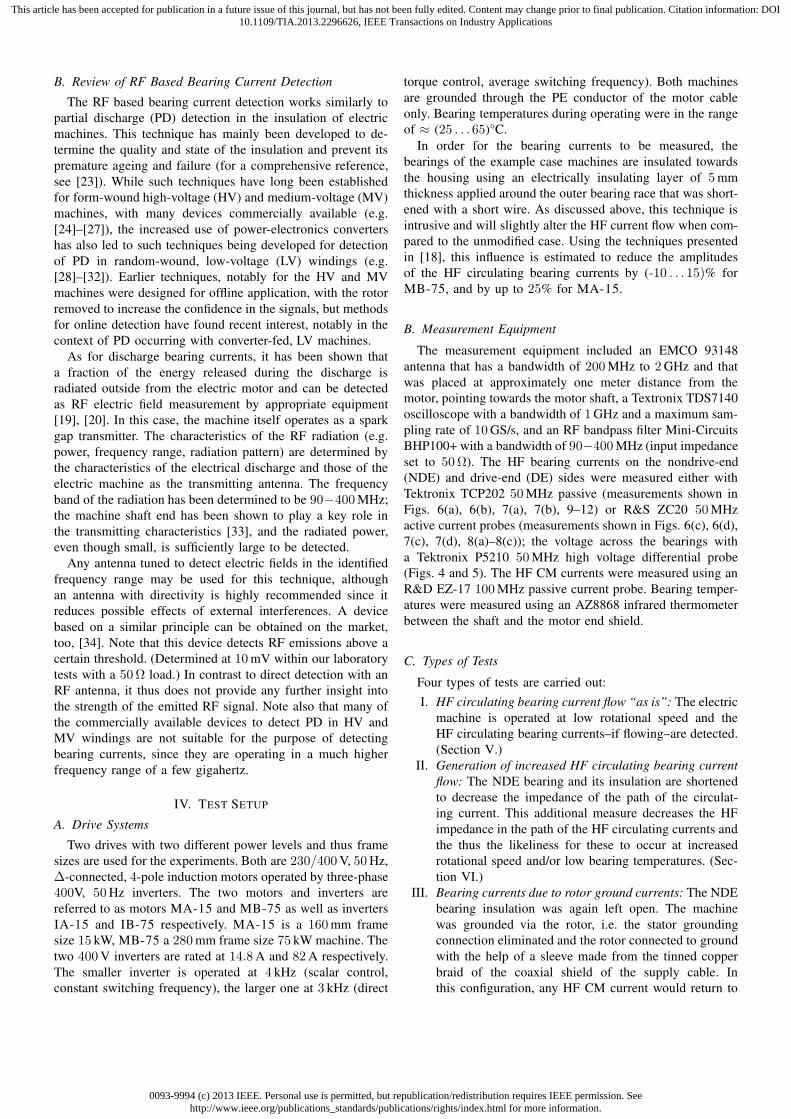
B. Experimental Results with Motor MB-75
With this machine, HF circulating bearing currents
occurred–along with discharge bearing currents–up to slightly
above 200 rpm rotational speed for lower bearing temperatures
in the range of some (20 . . .30)°C. Above, only discharge
bearing currents were observed. Maximum amplitudes of
these HF circulating bearing currents reached up to 1.2A
for 100 rpm. For elevated bearing temperatures above 60°C,
very small HF circulating bearing currents of a few hundred
milliamperes could be observed up to even 3000 rpm. The
HF CM current was measured to approximately 10A. The
frequency of the HF CM and the bearing currents was in the
range of 1MHz. As the bearing voltages and currents were
measured, too, the bearing current type could be verified for
any bearing currents detected through the non-intrusive RF
based method.
Conventionally, the HF circulating bearing current has been
understood to flow through the bearing that has mainly ohmic
behavior. During such purely ohmic behavior, there would be
an energy conversion due to ohmic loss within the bearing, but
no energy release as a result of a discharge. However, as shown
in Figs. 6(a)–6(d), also such HF circulating bearing currents
can be detected through the RF based method: The measured
HF bearing currents through the NDE and DE bearings have
the same waveforms and amplitudes and opposite signs, which
is a clear indicator of HF circulating bearing currents. The
moment the currents start to flow, an RF current pulse is
detected. This important finding will be further analyzed
below.
C. Analysis
The detected RF pulse indicates that some energy has been
released and radiated outside the machine the moment the
individual current has started to flow. A detailed consideration
of the voltages measured across the NDE and the DE bearings
shows a relatively steep voltage rise notably in one of the two
bearings (Figs. 6(a) and 6(b): NDE bearing, Figs. 6(c) and
6(d): DE bearing) the moment the current starts to flow. The
voltage and current waveforms are not fully proportional as
one would expect for purely ohmic behavior.
0093-9994 (c) 2013 IEEE. Personal use is permitted, but republication/redistribution requires IEEE permission. Seehttp://www.ieee.org/publications_standards/publications/rights/index.html for more information.
This article has been accepted for publication in a future issue of this journal, but has not been fully edited. Content may change prior to final publication. Citation information: DOI10.1109/TIA.2013.2296626, IEEE Transactions on Industry Applications
3 4 5 6 7 8 9 10
-1
0
1
Time [us]
Cu
rren
t[A
]
Inde
Ide
3 4 5 6 7 8 9 10-5
0
5
Time [us]
Vo
ltag
e[V
]
Unde
Ude
3 4 5 6 7 8 9 10
-2
0
2
x 10-3
Time [us]
Vo
ltag
e[V
]
RF
(a) 100 rpm rotational speed and ≈ 30°C bearing temperature.
3 4 5 6 7 8 9 10-1
0
1
Time [us]
Cu
rren
t[A
]
Inde
Ide
3 4 5 6 7 8 9 10-5
0
5
Time [us]
Vo
ltag
e[V
]
Unde
Ude
3 4 5 6 7 8 9 10
-2
0
2
x 10-3
Time [us]
Vo
ltag
e[V
]
RF
(b) 100 rpm rotational speed and ≈ 30°C bearing temperature.
1 2 3 4 5 6 7 8-1
0
1
Time (us)
Cu
rren
t[A
]
Inde
Ide
1 2 3 4 5 6 7 8
-2
0
2
Time (us)
Vo
ltag
e[V
]
Unde
Ude
1 2 3 4 5 6 7 8
-2
0
2
x 10-3
Time (us)
Vo
ltag
e[V
]
RF
(c) 400 rpm rotational speed and ≈ 55°C bearing temperature.
0 1 2 3 4 5 6 7-1
0
1
Time (us)
Cu
rren
t[A
]
Inde
Ide
0 1 2 3 4 5 6 7
-2
0
2
Time (us)
Vo
ltag
e[V
]
Unde
Ude
0 1 2 3 4 5 6 7
-2
0
2
x 10-3
Time (us)
Vo
ltag
e[V
]
RF
(d) 1500 rpm rotational speed and ≈ 65°C bearing temperature.
Fig. 6. Motor MB-75 and inverter IB-75: HF circulating bearing currentdetected through non-intrusive RF based method; measured currents, voltagesand RF signals.
We interpret this as follows: The moment the voltage in the
loop increases, the bearing lubricating film still has electrically
insulating properties. A certain voltage is required for the film
to lose these insulating properties. At a certain threshold, the
bearing(s) start(s) to conduct. In the case of discharge bearing
currents, the energy stored across the bearing(s) is released
instantaneously. In the present case of HF circulating bearing
currents some of this energy is absorbed by the change of the
electrical properties of the bearing. This reduces the bearing
impedance further whereby part of the energy is released and
radiated through the electric machine antenna structure.
With HF bearing currents–in contrast to the case with
discharge bearing currents–both bearings are required to have
electrically conducting properties. As observed in Figs. 6(a)–
6(d), the establishment of the current conducting path might
not be uniformly distributed across the two bearings: One
bearing might first suffer from a steeper voltage rise and
the subsequent voltage breakdown (thereby also releasing
energy that is eventually radiated through the machine antenna
structure) than the other. Note also that, depending on the
drive, some CM capacitive coupling might exist additionally.
Such voltage would add to the differential voltage induced by
the CM current generated HF flux, increasing the latter across
the one and decreasing it across the other bearing before the
HF circulating bearing current flow begins.
The energy released has been computed from the energy
stored in the total capacitance (two bearing capacitances and
one rotor-to frame capacitances) (eqs. (2) and (3) in [20], see
Appendix). The calculated values range between 10 and a few
100 nJ. This is within the lower part of the range of energies
released in the case of discharge bearing currents (between a
few and a few thousands of nanojoules). The latter explains
that the RF signals detected in the case of discharge bearing
currents were typically in the order of 10mV, whereas those
to detect HF circulating bearing currents were rather in the
range of a few millivolts.
Comparing Figs. 6(a) and 6(b), both show the relatively
steep voltage rise the moment the current starts to flow. The
detected RF pulse is larger for Fig. 6(b) where the voltage rises
faster and higher. However, note that the maximum bearing
current is larger in Fig. 6(a), indicating that the amplitudes of
the bearing current and of the RF pulse might not be strongly
related. The detected HF circulating bearing currents shown in
Figs. 6(c) and 6(d) occur not only at much higher rotational
speed, but also significantly higher bearing temperatures. Here,
much less voltage builds up before the current conducting path
is established resulting in much smaller emitted RF signals.
VI. RESULTS II: INCREASED HF CIRCULATING BEARING
CURRENT FLOW
A. Experimental Results with Motor MA-15
Some flow of HF circulating bearing currents in the smaller
machine could be generated through the decreased impedance
of the bearing current path. With this machine, the preliminary
findings were obtained that indicated the applicability of the
method and that led to further research on the larger machine.
For this reason they are also briefly mentioned in this paper.
0093-9994 (c) 2013 IEEE. Personal use is permitted, but republication/redistribution requires IEEE permission. Seehttp://www.ieee.org/publications_standards/publications/rights/index.html for more information.
This article has been accepted for publication in a future issue of this journal, but has not been fully edited. Content may change prior to final publication. Citation information: DOI10.1109/TIA.2013.2296626, IEEE Transactions on Industry Applications
However, these currents are much more rare with the small
machine, and the energies released were often found to be
so low that RF based detection was difficult. They will thus
not be discussed any further. However, we would like to point
out that this limitation does not impede on the practicability
of the proposed method: With HF circulating bearing currents
typically not occurring with machines with small frame sizes,
but if suffering from HF bearing currents, being put at risk due
to discharge bearing currents, there is no need to detect HF
circulating bearing currents with such machines, and detection
of discharge bearing currents through the RF method has been
well proven.
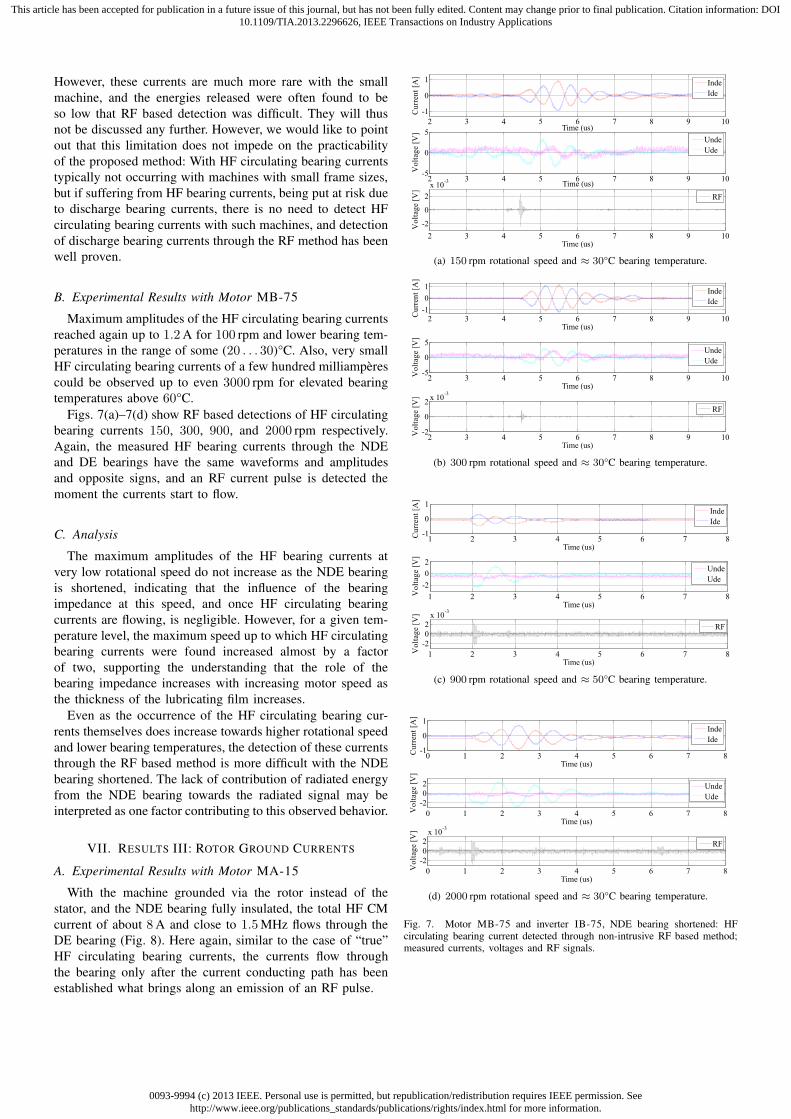
B. Experimental Results with Motor MB-75
Maximum amplitudes of the HF circulating bearing currents
reached again up to 1.2A for 100 rpm and lower bearing tem-
peratures in the range of some (20 . . . 30)°C. Also, very small
HF circulating bearing currents of a few hundred milliamperes
could be observed up to even 3000 rpm for elevated bearing
temperatures above 60°C.
Figs. 7(a)–7(d) show RF based detections of HF circulating
bearing currents 150, 300, 900, and 2000 rpm respectively.
Again, the measured HF bearing currents through the NDE
and DE bearings have the same waveforms and amplitudes
and opposite signs, and an RF current pulse is detected the
moment the currents start to flow.
C. Analysis
The maximum amplitudes of the HF bearing currents at
very low rotational speed do not increase as the NDE bearing
is shortened, indicating that the influence of the bearing
impedance at this speed, and once HF circulating bearing
currents are flowing, is negligible. However, for a given tem-
perature level, the maximum speed up to which HF circulating
bearing currents were found increased almost by a factor
of two, supporting the understanding that the role of the
bearing impedance increases with increasing motor speed as
the thickness of the lubricating film increases.
Even as the occurrence of the HF circulating bearing cur-
rents themselves does increase towards higher rotational speed
and lower bearing temperatures, the detection of these currents
through the RF based method is more difficult with the NDE
bearing shortened. The lack of contribution of radiated energy
from the NDE bearing towards the radiated signal may be
interpreted as one factor contributing to this observed behavior.
VII. RESULTS III: ROTOR GROUND CURRENTS
A. Experimental Results with Motor MA-15
With the machine grounded via the rotor instead of the
stator, and the NDE bearing fully insulated, the total HF CM
current of about 8A and close to 1.5MHz flows through the
DE bearing (Fig. 8). Here again, similar to the case of “true”
HF circulating bearing currents, the currents flow through
the bearing only after the current conducting path has been
established what brings along an emission of an RF pulse.
2 3 4 5 6 7 8 9 10
-1
0
1
Time (us)
Cu
rren
t[A
]
Inde
Ide
2 3 4 5 6 7 8 9 10-5
0
5
Time (us)
Vo
ltag
e[V
]
Unde
Ude
2 3 4 5 6 7 8 9 10
-2
0
2
x 10-3
Time (us)
Vo
ltag
e[V
]
RF
(a) 150 rpm rotational speed and ≈ 30°C bearing temperature.
2 3 4 5 6 7 8 9 10-1
0
1
Time (us)
Cu
rren
t[A
]
Inde
Ide
2 3 4 5 6 7 8 9 10-5
0
5
Time (us)
Vo
ltag
e[V
]
Unde
Ude
2 3 4 5 6 7 8 9 10-2
0
2x 10
-3
Time (us)
Vo
ltag
e[V
]RF
(b) 300 rpm rotational speed and ≈ 30°C bearing temperature.
1 2 3 4 5 6 7 8-1
0
1
Time (us)
Cu
rren
t[A
]
Inde
Ide
1 2 3 4 5 6 7 8
-2
0
2
Time (us)
Vo
ltag
e[V
]
Unde
Ude
1 2 3 4 5 6 7 8
-2
0
2
x 10-3
Time (us)
Vo
ltag
e[V
]
RF
(c) 900 rpm rotational speed and ≈ 50°C bearing temperature.
0 1 2 3 4 5 6 7 8-1
0
1
Time (us)
Cu
rren
t[A
]
Inde
Ide
0 1 2 3 4 5 6 7 8
-2
0
2
Time (us)
Vo
ltag
e[V
]
Unde
Ude
0 1 2 3 4 5 6 7 8
-2
0
2
x 10-3
Time (us)
Vo
ltag
e[V
]
RF
(d) 2000 rpm rotational speed and ≈ 30°C bearing temperature.
Fig. 7. Motor MB-75 and inverter IB-75, NDE bearing shortened: HFcirculating bearing current detected through non-intrusive RF based method;measured currents, voltages and RF signals.
0093-9994 (c) 2013 IEEE. Personal use is permitted, but republication/redistribution requires IEEE permission. Seehttp://www.ieee.org/publications_standards/publications/rights/index.html for more information.
This article has been accepted for publication in a future issue of this journal, but has not been fully edited. Content may change prior to final publication. Citation information: DOI10.1109/TIA.2013.2296626, IEEE Transactions on Industry Applications
0 1 2 3 4 5 6 7 8-10
0
10
Time (us)
Vb
[V]
0 1 2 3 4 5 6 7 8-10
0
10
Time (us)
I b[A
]
0 1 2 3 4 5 6 7 8-10
0
10
Time (us)
Ico
m[A
]
0 1 2 3 4 5 6 7 8-20
0
20
Time (us)
RF
[mV
]
(a) 900 rpm rotational speed and ≈ 35°C bearing temperature.
0 1 2 3 4 5 6 7 8-10
0
10
Time (us)
Vb
[V]
0 1 2 3 4 5 6 7 8-10
0
10
Time (us)
I b[A
]
0 1 2 3 4 5 6 7 8-10
0
10
Time (us)
Ico
m[A
]
0 1 2 3 4 5 6 7 8-10
0
10
Time (us)
RF
[mV
]
(b) 1800 rpm rotational speed and ≈ 50°C bearing temperature.
0 1 2 3 4 5 6 7 8-5
0
5
Time (us)
Vb
[V]
0 1 2 3 4 5 6 7 8-10
0
10
Time (us)
I b[A
]
0 1 2 3 4 5 6 7 8-10
0
10
Time (us)
Ico
m[A
]
0 1 2 3 4 5 6 7 8-10
0
10
Time (us)
RF
[mV
]
(c) 3000 rpm rotational speed and ≈ 50°C bearing temperature.
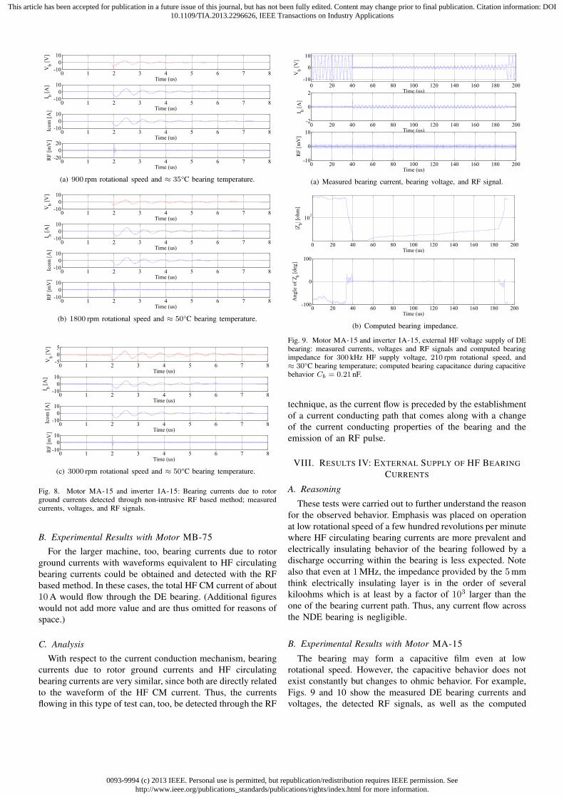
Fig. 8. Motor MA-15 and inverter IA-15: Bearing currents due to rotorground currents detected through non-intrusive RF based method; measuredcurrents, voltages, and RF signals.
B. Experimental Results with Motor MB-75
For the larger machine, too, bearing currents due to rotor
ground currents with waveforms equivalent to HF circulating
bearing currents could be obtained and detected with the RF
based method. In these cases, the total HF CM current of about
10A would flow through the DE bearing. (Additional figures
would not add more value and are thus omitted for reasons of
space.)
C. Analysis
With respect to the current conduction mechanism, bearing
currents due to rotor ground currents and HF circulating
bearing currents are very similar, since both are directly related
to the waveform of the HF CM current. Thus, the currents
flowing in this type of test can, too, be detected through the RF
0 20 40 60 80 100 120 140 160 180 200-10
0
10
Time (us)
Vb
[V]
0 20 40 60 80 100 120 140 160 180 200-2
0
2
Time (us)
I b[A
]
0 20 40 60 80 100 120 140 160 180 200-10
0
10
Time (us)
RF
[mV
]
(a) Measured bearing current, bearing voltage, and RF signal.
0 20 40 60 80 100 120 140 160 180 200
102
Time (us)
|Zb| [
oh
m]
0 20 40 60 80 100 120 140 160 180 200-100
0
100
Time (us)
An
gle
of
Z b[d
eg]
(b) Computed bearing impedance.
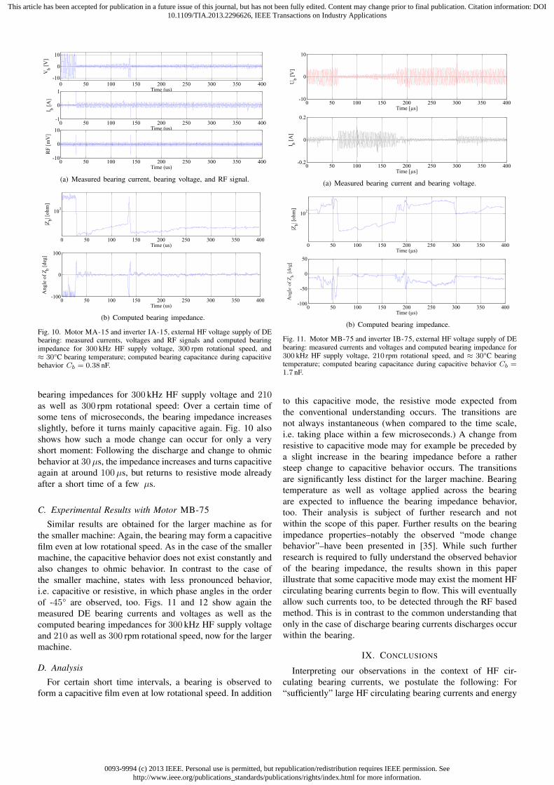
Fig. 9. Motor MA-15 and inverter IA-15, external HF voltage supply of DEbearing: measured currents, voltages and RF signals and computed bearingimpedance for 300 kHz HF supply voltage, 210 rpm rotational speed, and≈ 30°C bearing temperature; computed bearing capacitance during capacitivebehavior Cb = 0.21 nF.
technique, as the current flow is preceded by the establishment
of a current conducting path that comes along with a change
of the current conducting properties of the bearing and the
emission of an RF pulse.
VIII. RESULTS IV: EXTERNAL SUPPLY OF HF BEARING
CURRENTS
A. Reasoning
These tests were carried out to further understand the reason
for the observed behavior. Emphasis was placed on operation
at low rotational speed of a few hundred revolutions per minute
where HF circulating bearing currents are more prevalent and
electrically insulating behavior of the bearing followed by a
discharge occurring within the bearing is less expected. Note
also that even at 1MHz, the impedance provided by the 5mm
think electrically insulating layer is in the order of several
kiloohms which is at least by a factor of 103 larger than the
one of the bearing current path. Thus, any current flow across
the NDE bearing is negligible.
B. Experimental Results with Motor MA-15
The bearing may form a capacitive film even at low
rotational speed. However, the capacitive behavior does not
exist constantly but changes to ohmic behavior. For example,
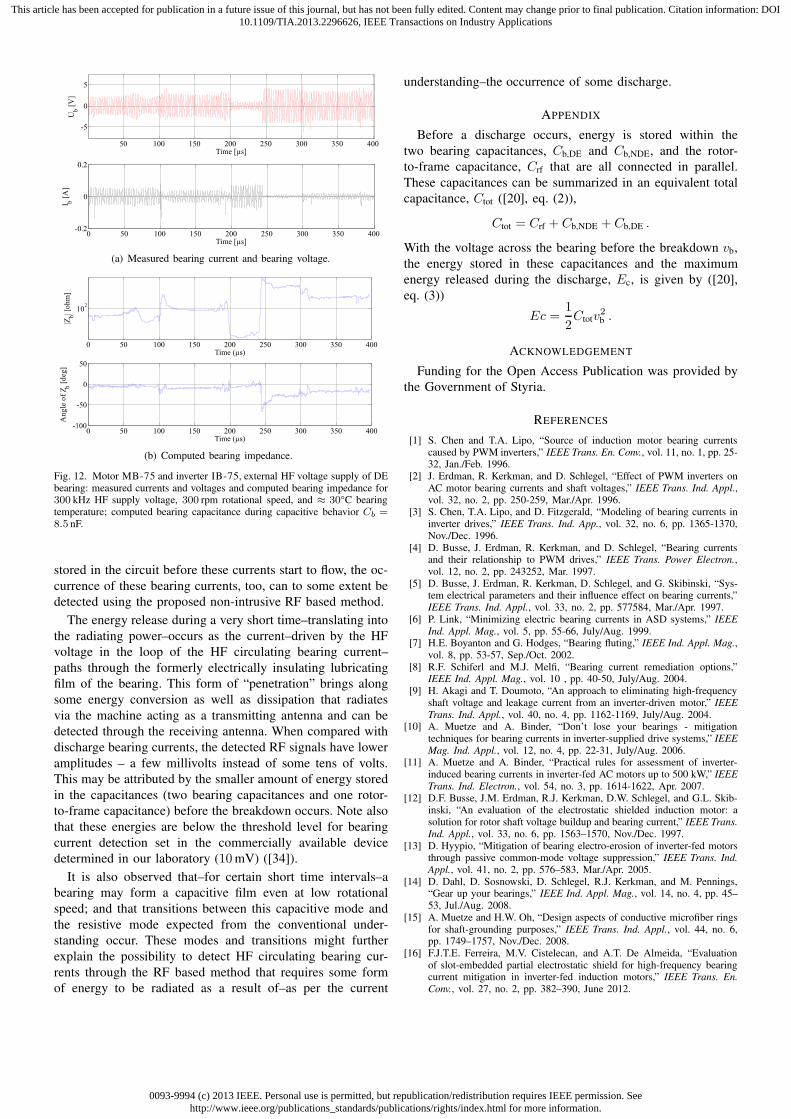
Figs. 9 and 10 show the measured DE bearing currents and
voltages, the detected RF signals, as well as the computed
0093-9994 (c) 2013 IEEE. Personal use is permitted, but republication/redistribution requires IEEE permission. Seehttp://www.ieee.org/publications_standards/publications/rights/index.html for more information.
This article has been accepted for publication in a future issue of this journal, but has not been fully edited. Content may change prior to final publication. Citation information: DOI10.1109/TIA.2013.2296626, IEEE Transactions on Industry Applications
0 50 100 150 200 250 300 350 400-10
0
10
Time (us)
Vb
[V]
0 50 100 150 200 250 300 350 400-1
0
1
Time (us)
I b[A
]
0 50 100 150 200 250 300 350 400-10
0
10
Time (us)
RF
[mV
]
(a) Measured bearing current, bearing voltage, and RF signal.
0 50 100 150 200 250 300 350 400
102
Time (us)
|Zb| [
oh
m]
0 50 100 150 200 250 300 350 400-100
0
100
Time (us)
An
gle
of
Z b[d
eg]
(b) Computed bearing impedance.
Fig. 10. Motor MA-15 and inverter IA-15, external HF voltage supply of DEbearing: measured currents, voltages and RF signals and computed bearingimpedance for 300 kHz HF supply voltage, 300 rpm rotational speed, and≈ 30°C bearing temperature; computed bearing capacitance during capacitivebehavior Cb = 0.38 nF.
bearing impedances for 300 kHz HF supply voltage and 210as well as 300 rpm rotational speed: Over a certain time of
some tens of microseconds, the bearing impedance increases
slightly, before it turns mainly capacitive again. Fig. 10 also
shows how such a mode change can occur for only a very
short moment: Following the discharge and change to ohmic
behavior at 30µs, the impedance increases and turns capacitive
again at around 100µs, but returns to resistive mode already
after a short time of a few µs.
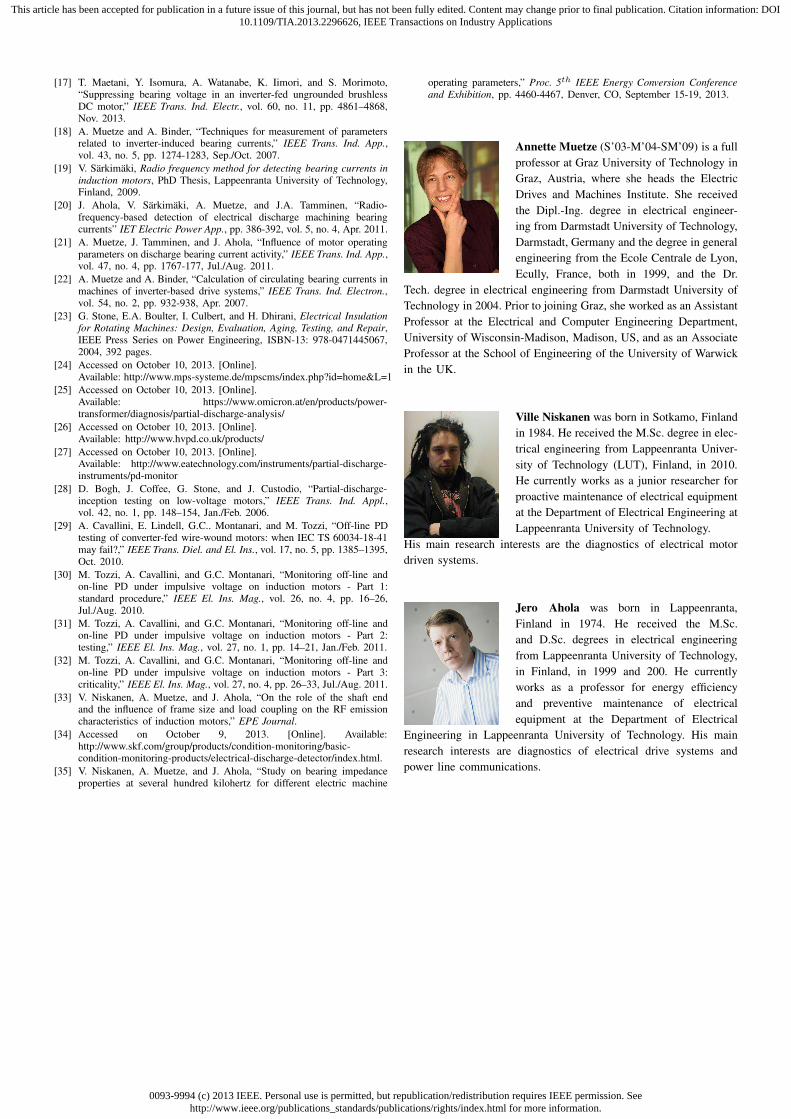
C. Experimental Results with Motor MB-75
Similar results are obtained for the larger machine as for
the smaller machine: Again, the bearing may form a capacitive
film even at low rotational speed. As in the case of the smaller
machine, the capacitive behavior does not exist constantly and
also changes to ohmic behavior. In contrast to the case of
the smaller machine, states with less pronounced behavior,
i.e. capacitive or resistive, in which phase angles in the order
of -45° are observed, too. Figs. 11 and 12 show again the
measured DE bearing currents and voltages as well as the
computed bearing impedances for 300 kHz HF supply voltage
and 210 as well as 300 rpm rotational speed, now for the larger
machine.
D. Analysis
For certain short time intervals, a bearing is observed to
form a capacitive film even at low rotational speed. In addition
0 50 100 150 200 250 300 350 400-10
0
10
Time [µs]
Ub
[V]
0 50 100 150 200 250 300 350 400-0.2
0
0.2
Time [µs]
I b[A
]
(a) Measured bearing current and bearing voltage.
0 50 100 150 200 250 300 350 400
102
Time (µs)
|Zb| [
oh
m]
0 50 100 150 200 250 300 350 400-100
-50
0
50
Time (µs)
An
gle
of
Zb
[deg
]
(b) Computed bearing impedance.
Fig. 11. Motor MB-75 and inverter IB-75, external HF voltage supply of DEbearing: measured currents and voltages and computed bearing impedance for300 kHz HF supply voltage, 210 rpm rotational speed, and ≈ 30°C bearingtemperature; computed bearing capacitance during capacitive behavior Cb =
1.7 nF.
to this capacitive mode, the resistive mode expected from
the conventional understanding occurs. The transitions are
not always instantaneous (when compared to the time scale,
i.e. taking place within a few microseconds.) A change from
resistive to capacitive mode may for example be preceded by
a slight increase in the bearing impedance before a rather
steep change to capacitive behavior occurs. The transitions
are significantly less distinct for the larger machine. Bearing
temperature as well as voltage applied across the bearing
are expected to influence the bearing impedance behavior,
too. Their analysis is subject of further research and not
within the scope of this paper. Further results on the bearing
impedance properties–notably the observed “mode change
behavior”–have been presented in [35]. While such further
research is required to fully understand the observed behavior
of the bearing impedance, the results shown in this paper
illustrate that some capacitive mode may exist the moment HF
circulating bearing currents begin to flow. This will eventually
allow such currents too, to be detected through the RF based
method. This is in contrast to the common understanding that
only in the case of discharge bearing currents discharges occur
within the bearing.
IX. CONCLUSIONS
Interpreting our observations in the context of HF cir-
culating bearing currents, we postulate the following: For
“sufficiently” large HF circulating bearing currents and energy
0093-9994 (c) 2013 IEEE. Personal use is permitted, but republication/redistribution requires IEEE permission. Seehttp://www.ieee.org/publications_standards/publications/rights/index.html for more information.
This article has been accepted for publication in a future issue of this journal, but has not been fully edited. Content may change prior to final publication. Citation information: DOI10.1109/TIA.2013.2296626, IEEE Transactions on Industry Applications
50 100 150 200 250 300 350 400
-5
0
5
Time [µs]
Ub
[V]
0 50 100 150 200 250 300 350 400-0.2
0
0.2
Time [µs]
I b[A
]
(a) Measured bearing current and bearing voltage.
0 50 100 150 200 250 300 350 400
102
Time (µs)
|Zb| [
oh
m]
0 50 100 150 200 250 300 350 400-100
-50
0
50
Time (µs)
An
gle
of
Z b[d
eg]
(b) Computed bearing impedance.
Fig. 12. Motor MB-75 and inverter IB-75, external HF voltage supply of DEbearing: measured currents and voltages and computed bearing impedance for300 kHz HF supply voltage, 300 rpm rotational speed, and ≈ 30°C bearingtemperature; computed bearing capacitance during capacitive behavior Cb =
8.5 nF.
stored in the circuit before these currents start to flow, the oc-
currence of these bearing currents, too, can to some extent be
detected using the proposed non-intrusive RF based method.
The energy release during a very short time–translating into
the radiating power–occurs as the current–driven by the HF
voltage in the loop of the HF circulating bearing current–
paths through the formerly electrically insulating lubricating
film of the bearing. This form of “penetration” brings along
some energy conversion as well as dissipation that radiates
via the machine acting as a transmitting antenna and can be
detected through the receiving antenna. When compared with
discharge bearing currents, the detected RF signals have lower
amplitudes – a few millivolts instead of some tens of volts.
This may be attributed by the smaller amount of energy stored
in the capacitances (two bearing capacitances and one rotor-
to-frame capacitance) before the breakdown occurs. Note also
that these energies are below the threshold level for bearing
current detection set in the commercially available device
determined in our laboratory (10mV) ([34]).
It is also observed that–for certain short time intervals–a
bearing may form a capacitive film even at low rotational
speed; and that transitions between this capacitive mode and
the resistive mode expected from the conventional under-
standing occur. These modes and transitions might further
explain the possibility to detect HF circulating bearing cur-
rents through the RF based method that requires some form
of energy to be radiated as a result of–as per the current
understanding–the occurrence of some discharge.
APPENDIX
Before a discharge occurs, energy is stored within the
two bearing capacitances, Cb,DE and Cb,NDE, and the rotor-
to-frame capacitance, Crf that are all connected in parallel.
These capacitances can be summarized in an equivalent total
capacitance, Ctot ([20], eq. (2)),
Ctot = Crf + Cb,NDE + Cb,DE .
With the voltage across the bearing before the breakdown vb,
the energy stored in these capacitances and the maximum
energy released during the discharge, Ec, is given by ([20],
eq. (3))
Ec =1
2Ctotv
2
b .
ACKNOWLEDGEMENT
Funding for the Open Access Publication was provided by
the Government of Styria.
REFERENCES
[1] S. Chen and T.A. Lipo, “Source of induction motor bearing currentscaused by PWM inverters,” IEEE Trans. En. Conv., vol. 11, no. 1, pp. 25-32, Jan./Feb. 1996.
[2] J. Erdman, R. Kerkman, and D. Schlegel, “Effect of PWM inverters onAC motor bearing currents and shaft voltages,” IEEE Trans. Ind. Appl.,vol. 32, no. 2, pp. 250-259, Mar./Apr. 1996.
[3] S. Chen, T.A. Lipo, and D. Fitzgerald, “Modeling of bearing currents ininverter drives,” IEEE Trans. Ind. App., vol. 32, no. 6, pp. 1365-1370,Nov./Dec. 1996.
[4] D. Busse, J. Erdman, R. Kerkman, and D. Schlegel, “Bearing currentsand their relationship to PWM drives,” IEEE Trans. Power Electron.,vol. 12, no. 2, pp. 243252, Mar. 1997.
[5] D. Busse, J. Erdman, R. Kerkman, D. Schlegel, and G. Skibinski, “Sys-tem electrical parameters and their influence effect on bearing currents,”IEEE Trans. Ind. Appl., vol. 33, no. 2, pp. 577584, Mar./Apr. 1997.
[6] P. Link, “Minimizing electric bearing currents in ASD systems,” IEEE
Ind. Appl. Mag., vol. 5, pp. 55-66, July/Aug. 1999.[7] H.E. Boyanton and G. Hodges, “Bearing fluting,” IEEE Ind. Appl. Mag.,
vol. 8, pp. 53-57, Sep./Oct. 2002.[8] R.F. Schiferl and M.J. Melfi, “Bearing current remediation options,”
IEEE Ind. Appl. Mag., vol. 10 , pp. 40-50, July/Aug. 2004.[9] H. Akagi and T. Doumoto, “An approach to eliminating high-frequency
shaft voltage and leakage current from an inverter-driven motor,” IEEE
Trans. Ind. Appl., vol. 40, no. 4, pp. 1162-1169, July/Aug. 2004.[10] A. Muetze and A. Binder, “Don’t lose your bearings - mitigation
techniques for bearing currents in inverter-supplied drive systems,” IEEE
Mag. Ind. Appl., vol. 12, no. 4, pp. 22-31, July/Aug. 2006.[11] A. Muetze and A. Binder, “Practical rules for assessment of inverter-
induced bearing currents in inverter-fed AC motors up to 500 kW,” IEEE
Trans. Ind. Electron., vol. 54, no. 3, pp. 1614-1622, Apr. 2007.[12] D.F. Busse, J.M. Erdman, R.J. Kerkman, D.W. Schlegel, and G.L. Skib-
inski, “An evaluation of the electrostatic shielded induction motor: asolution for rotor shaft voltage buildup and bearing current,” IEEE Trans.
Ind. Appl., vol. 33, no. 6, pp. 1563–1570, Nov./Dec. 1997.[13] D. Hyypio, “Mitigation of bearing electro-erosion of inverter-fed motors
through passive common-mode voltage suppression,” IEEE Trans. Ind.
Appl., vol. 41, no. 2, pp. 576–583, Mar./Apr. 2005.[14] D. Dahl, D. Sosnowski, D. Schlegel, R.J. Kerkman, and M. Pennings,
“Gear up your bearings,” IEEE Ind. Appl. Mag., vol. 14, no. 4, pp. 45–53, Jul./Aug. 2008.
[15] A. Muetze and H.W. Oh, “Design aspects of conductive microfiber ringsfor shaft-grounding purposes,” IEEE Trans. Ind. Appl., vol. 44, no. 6,pp. 1749–1757, Nov./Dec. 2008.
[16] F.J.T.E. Ferreira, M.V. Cistelecan, and A.T. De Almeida, “Evaluationof slot-embedded partial electrostatic shield for high-frequency bearingcurrent mitigation in inverter-fed induction motors,” IEEE Trans. En.
Conv., vol. 27, no. 2, pp. 382–390, June 2012.
0093-9994 (c) 2013 IEEE. Personal use is permitted, but republication/redistribution requires IEEE permission. Seehttp://www.ieee.org/publications_standards/publications/rights/index.html for more information.
This article has been accepted for publication in a future issue of this journal, but has not been fully edited. Content may change prior to final publication. Citation information: DOI10.1109/TIA.2013.2296626, IEEE Transactions on Industry Applications
[17] T. Maetani, Y. Isomura, A. Watanabe, K. Iimori, and S. Morimoto,“Suppressing bearing voltage in an inverter-fed ungrounded brushlessDC motor,” IEEE Trans. Ind. Electr., vol. 60, no. 11, pp. 4861–4868,Nov. 2013.
[18] A. Muetze and A. Binder, “Techniques for measurement of parametersrelated to inverter-induced bearing currents,” IEEE Trans. Ind. App.,vol. 43, no. 5, pp. 1274-1283, Sep./Oct. 2007.
[19] V. Sarkimaki, Radio frequency method for detecting bearing currents in
induction motors, PhD Thesis, Lappeenranta University of Technology,Finland, 2009.
[20] J. Ahola, V. Sarkimaki, A. Muetze, and J.A. Tamminen, “Radio-frequency-based detection of electrical discharge machining bearingcurrents” IET Electric Power App., pp. 386-392, vol. 5, no. 4, Apr. 2011.
[21] A. Muetze, J. Tamminen, and J. Ahola, “Influence of motor operatingparameters on discharge bearing current activity,” IEEE Trans. Ind. App.,vol. 47, no. 4, pp. 1767-177, Jul./Aug. 2011.
[22] A. Muetze and A. Binder, “Calculation of circulating bearing currents inmachines of inverter-based drive systems,” IEEE Trans. Ind. Electron.,vol. 54, no. 2, pp. 932-938, Apr. 2007.
[23] G. Stone, E.A. Boulter, I. Culbert, and H. Dhirani, Electrical Insulationfor Rotating Machines: Design, Evaluation, Aging, Testing, and Repair,IEEE Press Series on Power Engineering, ISBN-13: 978-0471445067,2004, 392 pages.
[24] Accessed on October 10, 2013. [Online].Available: http://www.mps-systeme.de/mpscms/index.php?id=home&L=1
[25] Accessed on October 10, 2013. [Online].Available: https://www.omicron.at/en/products/power-transformer/diagnosis/partial-discharge-analysis/
[26] Accessed on October 10, 2013. [Online].Available: http://www.hvpd.co.uk/products/
[27] Accessed on October 10, 2013. [Online].Available: http://www.eatechnology.com/instruments/partial-discharge-instruments/pd-monitor
[28] D. Bogh, J. Coffee, G. Stone, and J. Custodio, “Partial-discharge-inception testing on low-voltage motors,” IEEE Trans. Ind. Appl.,vol. 42, no. 1, pp. 148–154, Jan./Feb. 2006.
[29] A. Cavallini, E. Lindell, G.C.. Montanari, and M. Tozzi, “Off-line PDtesting of converter-fed wire-wound motors: when IEC TS 60034-18-41may fail?,” IEEE Trans. Diel. and El. Ins., vol. 17, no. 5, pp. 1385–1395,Oct. 2010.
[30] M. Tozzi, A. Cavallini, and G.C. Montanari, “Monitoring off-line andon-line PD under impulsive voltage on induction motors - Part 1:standard procedure,” IEEE El. Ins. Mag., vol. 26, no. 4, pp. 16–26,Jul./Aug. 2010.
[31] M. Tozzi, A. Cavallini, and G.C. Montanari, “Monitoring off-line andon-line PD under impulsive voltage on induction motors - Part 2:testing,” IEEE El. Ins. Mag., vol. 27, no. 1, pp. 14–21, Jan./Feb. 2011.
[32] M. Tozzi, A. Cavallini, and G.C. Montanari, “Monitoring off-line andon-line PD under impulsive voltage on induction motors - Part 3:criticality,” IEEE El. Ins. Mag., vol. 27, no. 4, pp. 26–33, Jul./Aug. 2011.
[33] V. Niskanen, A. Muetze, and J. Ahola, “On the role of the shaft endand the influence of frame size and load coupling on the RF emissioncharacteristics of induction motors,” EPE Journal.
[34] Accessed on October 9, 2013. [Online]. Available:http://www.skf.com/group/products/condition-monitoring/basic-condition-monitoring-products/electrical-discharge-detector/index.html.
[35] V. Niskanen, A. Muetze, and J. Ahola, “Study on bearing impedanceproperties at several hundred kilohertz for different electric machine
operating parameters,” Proc. 5th IEEE Energy Conversion Conference
and Exhibition, pp. 4460-4467, Denver, CO, September 15-19, 2013.
Annette Muetze (S’03-M’04-SM’09) is a full
professor at Graz University of Technology in
Graz, Austria, where she heads the Electric
Drives and Machines Institute. She received
the Dipl.-Ing. degree in electrical engineer-
ing from Darmstadt University of Technology,
Darmstadt, Germany and the degree in general
engineering from the Ecole Centrale de Lyon,
Ecully, France, both in 1999, and the Dr.
Tech. degree in electrical engineering from Darmstadt University of
Technology in 2004. Prior to joining Graz, she worked as an Assistant
Professor at the Electrical and Computer Engineering Department,
University of Wisconsin-Madison, Madison, US, and as an Associate
Professor at the School of Engineering of the University of Warwick
in the UK.
Ville Niskanen was born in Sotkamo, Finland
in 1984. He received the M.Sc. degree in elec-
trical engineering from Lappeenranta Univer-
sity of Technology (LUT), Finland, in 2010.
He currently works as a junior researcher for
proactive maintenance of electrical equipment
at the Department of Electrical Engineering at
Lappeenranta University of Technology.
His main research interests are the diagnostics of electrical motor
driven systems.
Jero Ahola was born in Lappeenranta,
Finland in 1974. He received the M.Sc.
and D.Sc. degrees in electrical engineering
from Lappeenranta University of Technology,
in Finland, in 1999 and 200. He currently
works as a professor for energy efficiency
and preventive maintenance of electrical
equipment at the Department of Electrical
Engineering in Lappeenranta University of Technology. His main
research interests are diagnostics of electrical drive systems and
power line communications.


