

Contents
Thank you for purchasing the Onkyo AV Receiver.Please read this manual thoroughly before makingconnections and plugging in the unit. Following theinstructions in this manual will enable you to obtainoptimum performance and listening enjoyment fromyour new AV Receiver. Please retain this manual forfuture reference.
TX-SR700/700ETX-SR600/600E
Appendix 76
Remote controller 63
Setup and operation 36
Before using 2
AV Receiver
Instruction ManualFacilities and connections 8

2
1. Read Instructions – All the safety and operating instructionsshould be read before the appliance is operated.
2. Retain Instructions – The safety and operating instructionsshould be retained for future reference.
3. Heed Warnings – All warnings on the appliance and in theoperating instructions should be adhered to.
4. Follow Instructions – All operating and use instructionsshould be followed.
5. Cleaning – Unplug the appliance from the wall outlet beforecleaning. The appliance should be cleaned only as recom-mended by the manufacturer.
6. Attachments – Do not use attachments not recommended bythe appliance manufacturer as they may cause hazards.
7. Water and Moisture – Do not use the appliance near water –forexample, near a bath tub, wash bowl, kitchen sink, or laundrytub; in a wet basement; or near a swimming pool; and the like.
8. Accessories – Do not place the appliance on an unstable cart,stand, tripod, bracket, or table. The appliance may fall, causingserious injury to a child or adult, and serious damage to theappliance. Use only with a cart, stand, tripod, bracket, or tablerecommended by the manufacturer, or sold with the appliance.Any mounting of the appliance should follow themanufacturer’s instructions, andshould use a mounting accessoryrecommended by the manufac-turer.
9. An appliance and cart combina-tion should be moved with care.Quick stops, excessive force, anduneven surfaces may cause theappliance and cart combination tooverturn.
10. Ventilation – Slots and openings in the cabinet are providedfor ventilation and to ensure reliable operation of the applianceand to protect it from overheating, and these openings must notbe blocked or covered. The openings should never be blockedby placing the appliance on a bed, sofa, rug, or other similarsurface. The appliance should not be placed in a built-in instal-lation such as a bookcase or rack unless proper ventilation isprovided. There should be free space of at least 20 cm (8 in.)and an opening behind the appliance.
11. Power Sources – The appliance should be operated only fromthe type of power source indicated on the marking label. If youare not sure of the type of power supply to your home, consultyour appliance dealer or local power company.
12. Grounding or Polarization – The appliance may be equippedwith a polarized alternating current line plug (a plug having oneblade wider than the other). This plug will fit into the poweroutlet only one way. This is a safety feature. If you are unable toinsert the plug fully into the outlet, try reversing the plug. If theplug should still fail to fit, contact your electrician to replaceyour obsolete outlet. Do not defeat the safety purpose of thepolarized plug.
13. Power-Cord Protection – Power-supply cords should berouted so that they are not likely to be walked on or pinched byitems placed upon or against them, paying particular attentionto cords at plugs, convenience receptacles, and the point wherethey exit from the appliance.
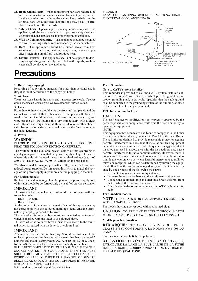
14. Outdoor Antenna Grounding – If an outside antenna or cablesystem is connected to the appliance, be sure the antenna orcable system is grounded so as to provide some protectionagainst voltage surges and built-up static charges. Article 810of the National Electrical Code, ANSI/NFPA 70, provides in-formation with regard to proper grounding of the mast and sup-porting structure, grounding of the lead-in wire to an antenna-discharge unit, size of grounding conductors, location of an-tenna-discharge unit, connection to grounding electrodes, andrequirements for the grounding electrode. See Figure 1.
15. Lightning – For added protection for the appliance during alightning storm, or when it is left unattended and unused forlong periods of time, unplug it from the wall outlet and discon-nect the antenna or cable system. This will prevent damage tothe appliance due to lightning and power-line surges.
16. Power Lines – An outside antenna system should not be lo-cated in the vicinity of overhead power lines or other electriclight or power circuits, or where it can fall into such power linesor circuits. When installing an outside antenna system, extremecare should be taken to keep from touching such power lines orcircuits as contact with them might be fatal.
17. Overloading – Do not overload wall outlets, extension cords,or integral convenience receptacles as this can result in a riskof fire or electric shock.
18. Object and Liquid Entry – Never push objects of any kindinto the appliance through openings as they may touch danger-ous voltage points or short-out parts that could result in a fire orelectric shock. Never spill liquid of any kind on the appliance.
19. Servicing – Do not attempt to service the appliance yourself asopening or removing covers may expose you to dangerous volt-age or other hazards. Refer all servicing to qualified servicepersonnel.
20. Damage Requiring Service – Unplug the appliance form thewall outlet and refer servicing to qualified service personnelunder the following conditions:A. When the power-supply cord or plug is damaged,B. If liquid has been spilled, or objects have fallen into the
appliance,C. If the appliance has been exposed to rain or water,D. If the appliance does not operate normally by following the
operating instructions. Adjust only those controls that arecovered by the operating instructions as an improper ad-justment of other controls may result in damage and willoften require extensive work by a qualified technician torestore the appliance to its normal operation,
E. If the appliance has been dropped or damaged in any way,and
F. When the appliance exhibits a distinct change in perfor-mance – this indicates a need for service.
Important Safeguards
WARNING:TO REDUCE THE RISK OF FIRE OR ELECTRIC SHOCK, DO NOT EXPOSE THIS APPLIANCE TO RAIN OR MOISTURE.
CAUTION:TO REDUCE THE RISK OF ELECTRIC SHOCK, DO NOT REMOVE COVER (OR BACK). NO USER-SERVICEABLE PARTS INSIDE. REFER SERVICING TO QUALIFIED SERVICE PERSONNEL.
The lightning flash with arrowhead symbol, within an equilateral triangle, is intended to alert the user to the presence of uninsulated “dangerous voltage” within the product’s enclosure that may be of sufficient magnitude to constitute a risk of electric shock to persons.
The exclamation point within an equilateral triangle is intended to alert the user to the presence of important operating and maintenance (servicing) instructions in the literature accompanying the appliance.
WARNINGRISK OF ELECTRIC SHOCK
DO NOT OPENRISQUE DE CHOC ELECTRIQUE
NE PAS OUVRIR
AVIS
PORTABLE CART WARNING
S3125A
3
ANTENNADISCHARGE UNIT(NEC SECTION 810-20)
GROUNDING CONDUCTORS(NEC SECTION 810-21)
GROUND CLAMPS
POWER SERVICE GROUNDINGELECTRODE SYSTEM(NEC ART 250, PART H)
NEC – NATIONAL ELECTRICAL CODE
ELECTRICSERVICEEQUIPMENT
GROUNDCLAMP
ANTENNALEAD INWIRE
S2898A
1. Recording CopyrightRecording of copyrighted material for other than personal use isillegal without permission of the copyright holder.
2. AC FuseThe fuse is located inside the chassis and is not user-serviceable. If powerdoes not come on, contact your Onkyo authorized service station.
3. CareFrom time to time you should wipe the front and rear panels and thecabinet with a soft cloth. For heavier dirt, dampen a soft cloth in aweak solution of mild detergent and water, wring it out dry, andwipe off the dirt. Following this, dry immediately with a cleancloth. Do not use rough material, thinners, alcohol or other chemi-cal solvents or cloths since these could damage the finish or removethe panel lettering.
4. Power
WARNINGBEFORE PLUGGING IN THE UNIT FOR THE FIRST TIME,READ THE FOLLOWING SECTION CAREFULLY.
The voltage of the available power supply differs according tocountry or region. Be sure that the power supply voltage of the areawhere this unit will be used meets the required voltage (e.g., AC230 V, 50 Hz or AC 120 V, 60 Hz) written on the rear panel.
Worldwide models are equipped with a voltage selector to conformto local power supplies. Be sure to set this switch to match the volt-age of the power supply in your area before plugging in the unit.
For British modelsReplacement and mounting of an AC plug on the power supply cordof this unit should be performed only by qualified service personnel.
IMPORTANTThe wires in the mains lead are coloured in accordance with thefollowing code:
Blue : NeutralBrown : Live
As the colours of the wires in the mains lead of this apparatus maynot correspond with the coloured markings identifying the termi-nals in your plug, proceed as follows:The wire which is coloured blue must be connected to the terminalwhich is marked with the letter N or coloured black.The wire which is coloured brown must be connected to the termi-nal which is marked with the letter L or coloured red.
IMPORTANTA 5 ampere fuse is fitted in this plug. Should the fuse need to bereplaced, please ensure that the replacement fuse has a rating of 5amperes and that it is approved by ASTA or BSI to BS1362. Checkfor the ASTA mark or the BSI mark on the body of the fuse.IF THE FITTED MOULDED PLUG IS UNSUITABLE FOR THESOCKET OUTLET IN YOUR HOME THEN THE FUSESHOULD BE REMOVED AND THE PLUG CUT OFF AND DIS-POSED OF SAFELY. THERE IS A DANGER OF SEVEREELECTRICAL SHOCK IF THE CUT OFF PLUG IS INSERTEDINTO ANY 13 AMPERE SOCKET.If in any doubt, consult a qualified electrician.
PrecautionsFor U.S. modelsNote to CATV system installer:This reminder is provided to call the CATV system installer’s at-tention to Section 820-40 of the NEC which provides guidelines forproper grounding and, in particular, specifies that the cable groundshall be connected to the grounding system of the building, as closeto the point of cable entry as practical.
FCC Information for User
CAUTION:The user changes or modifications not expressly approved by theparty responsible for compliance could void the user’s authority tooperate the equipment.NOTE:This equipment has been tested and found to comply with the limitsfor a Class B digital device, pursuant to Part 15 of the FCC Rules.These limits are designed to provide reasonable protection againstharmful interference in a residential installation. This equipmentgenerates, uses and can radiate radio frequency energy and, if notinstalled and used in accordance with the instructions, may causeharmful interference to radio communications. However, there isno guarantee that interference will not occur in a particular installa-tion. If this equipment does cause harmful interference to radio ortelevision reception, which can be determined by turning the equip-ment off and on, the user is encouraged to try to correct the interfer-ence by one or more of the following measures:• Reorient or relocate the receiving antenna.• Increase the separation between the equipment and receiver.• Connect the equipment into an outlet on a circuit different from
that to which the receiver is connected.• Consult the dealer or an experienced radio/TV technician for
help.
For Canadian models
NOTE: THIS CLASS B DIGITAL APPARATUS COMPLIESWITH CANADIAN ICES-003.
For models having a power cord with a polarized plug:
CAUTION: TO PREVENT ELECTRIC SHOCK, MATCHWIDE BLADE OF PLUG TO WIDE SLOT, FULLY INSERT.
Modèle pour les Canadien
REMARQUE: CET APPAREIL NUMÉRIQUE DE LACLASSE B EST CON-FORME À LA NORME NMB-003 DUCANADA.
Sur les modèles dont la fiche est polarisée:
ATTENTION: POUR ÉVITER LES CHOCS ÉLECTRIQUES,INTRODUIRE LA LAME LA PLUS LARGE DE LA FICHEDANS LA BORNE CORRESPONDANTE DE LA PRISE ETPOUSSER JUSQU’AU FOND.
21. Replacement Parts – When replacement parts are required, besure the service technician has used replacement parts specifiedby the manufacturer or have the same characteristics as theoriginal part. Unauthorized substitutions may result in fire,electric shock, or other hazards.
22. Safety Check – Upon completion of any service or repairs to theappliance, ask the service technician to perform safety checks todetermine that the appliance is in proper operation condition.
23. Wall or Ceiling Mounting – The appliance should be mountedto a wall or ceiling only as recommended by the manufacturer.
24. Heat – The appliance should be situated away from heatsources such as radiators, heat registers, stoves, or other appli-ances (including amplifiers) that produce heat.
25. Liquid Hazards – The appliance shall not be exposed to drip-ping or splashing and no objects filled with liquids, such asvases shall be placed on the appliance.
FIGURE 1:EXAMPLE OF ANTENNA GROUNDING AS PER NATIONALELECTRICAL CODE, ANSI/NFPA 70
4
Contents
Before using
Important Safeguards......................................... 2
Precautions ......................................................... 3
Contents .............................................................. 4
Features ............................................................... 6
Supplied accessories ......................................... 7
Before using this unit ......................................... 7Setting the voltage selector
(Worldwide models only) ......................................... 7
Installing the remote controller batteries ......................... 7
Using the remote controller .............................................. 7
Facilities and connections
Front panel facilities ........................................... 8
Front panel .......................................................... 8
Front panel display ........................................... 11
Remote controller ............................................. 12
Connections ...................................................... 14
Connections (TX-SR700/700E) ........................ 16Connecting your audio components .............................. 16
Connecting your video components .............................. 17
12V TRIGGER ZONE 2 terminal .................................. 21
PRE OUT ........................................................................ 21
Operating components not reached by theremote controller signals (IR IN) (TX-SR700/700E only) ..................................................... 22If the remote controller signal does not reach the TX-
SR700/700E remote sensor .................................... 22
Connecting the remote zone (Zone 2) speakers(TX-SR700/700E only) .................................. 23When using the ZONE 2 SPEAKERS terminals ........... 23
When using the ZONE 2 PRE OUT terminals .............. 23
AC OUTLETS ................................................................ 29
REMOTE CONTROL ............................................. 29
Connections (TX-SR600/600E) ........................ 24Connecting your audio components .............................. 24
Connecting your video components .............................. 25
AC OUTLETS ................................................................ 29
REMOTE CONTROL ............................................. 29
Connecting speakers ....................................... 30Standard speaker setup for surround sound ................... 30
Minimum speaker configuration for
surround sound playback ........................................ 30
Speaker placement .......................................................... 30
Using the speaker labels ................................................. 30
Connecting speakers ....................................................... 31
Connecting the speaker cable ......................................... 31
Connecting a subwoofer ................................................. 31
Connecting to the SPEAKERS B terminals
(TX-SR600/600E only) .......................................... 31
Connecting the power ...................................... 33Turning on the power ..................................................... 33
Turning on the power from the remote controller ........ 33
Connecting antennas ....................................... 34Assembling the AM loop antenna .................................. 34
Connecting the AM antenna cable ................................. 34
Connecting the included antennas ................................. 34
Connecting an FM outdoor antenna ............................... 35
Connecting an AM outdoor antenna .............................. 35
Directional linkage ......................................................... 35
Connecting the antenna cable to the 75/300 Ω antenna
adapter (For all models other than USA &
Canadian models and European models) ............... 35
Setup and operation
Configuring the speakers ................................ 36Displaying the Main Menu ............................................ 36
Speaker Configuration ................................................... 36
Setting the speaker distance from
your normal listening position ................................ 38
Calibrating the speaker levels ........................................ 38
Buttons used for navigating through the menus ............ 39
Listening to Radio Broadcasts ........................ 40Tuning into a radio station ............................................. 40
Listening to a stereo radio station (FM mode) .............. 40
Presetting a radio station ................................................ 41
Selecting a preset radio station ...................................... 41
Erasing a preset radio station ......................................... 41
Listening to RDS broadcasts (European modelsonly) .............................................................. 42Listening to RDS broadcasts .......................................... 42
PTY program types in Europe ........................................ 42
Displaying Radio Text (RT) ........................................... 43
Performing a PTY scan .................................................. 43
Performing a TP scan ..................................................... 43

5
Contents
Declaration of Conformity
We, ONKYO EUROPEELECTRONICS GmbHINDUSTRIESTRASSE 2082110 GERMERING,GERMANY
GERMERING, GERMANY
ONKYO EUROPE ELECTRONICS GmbH
I. MORI
declare in own responsibility, that the ONKYO product describedin this instruction manual is in compliance with the corresponding technical standards such as EN60065, EN55013, EN55020 and EN61000-3-2, -3-3.
Selecting an Audio Component ...................... 44Basic operation (TX-SR700/700E) ................................ 44
Basic operation (TX-SR600/600E) ................................ 45
Selecting speakers (SPEAKERS A, B)
(TX-SR600/600E only) .......................................... 45
Selecting the type of audio input signal ......................... 46
Temporarily changing the speaker output levels ........... 46
To change the display of the input source
from TAPE to MD................................................... 46
Using the sleep time (remote controller only) ............... 47
Listening with headphones ............................................. 47
Enjoying DVD multichannel audio playback ................ 47
Switching the display ..................................................... 48
Temporarily turning off the sound ................................. 48
Listening Modes ............................................... 49Selecting a listening mode ............................................. 51
Original filter (CinemaFILTER) loading for movies .... 52
Input Setup ........................................................ 53
OSD Setup and Other Settings........................ 56OSD Setup ...................................................................... 56
Preference ....................................................................... 56
Audio Adjust ...................................................... 57
Enjoying music in the remote zone(TX-SR700/700E only) .................................. 60Using the buttons on the TX-SR700/700E .................... 60
Using the remote controller ............................................ 60
Adjusting the volume for the remote zone .................... 60
Recording a source (TX-SR700/700E) ............ 61To record the input source signal you are currently
watching or listening to .......................................... 61
To record an input source signal different from that you
are currently watching or listening to ..................... 61
Recording a source (TX-SR600/600E) ............ 62To record the input source signal you are currently
watching or listening to .......................................... 62
Remote controller
Using remote controller ................................... 63Overview ........................................................................ 63
Calling up a preset radio station .................................... 63
Controlling an Onkyo cassette tape deck ...................... 63
Controlling an Onkyo CD player ................................... 64
Controlling an Onkyo DVD player ................................ 65
Controlling an Onkyo MD recorder ............................... 66
VCR and TV MODE buttons ......................................... 66
Entering a pre-programming code.................. 67Learning a pre-programming code ................................. 67
Pre-programming codes ................................................. 68
Operating your programmedremote controller ......................................... 69DVD MODE (DVD Player Mode) ................................ 69
VCR MODE (VCR Mode) ............................................. 69
TV MODE (TV Mode) ................................................... 69
Programming the commands of remotecontrollers for other devices into theremote controller ......................................... 70Programming procedure ................................................. 70
Erasing the programmed command from one button .... 72
Erasing all the commands programmed under a MODE
button ....................................................................... 72
Using the macro function ................................ 73What is the macro function? .......................................... 73
Programming the macro ................................................. 73
Executing the macro ....................................................... 73
Erasing a macro from the MACRO 1 (or 2) button ...... 74
Erasing all commands and macros that have been
programmed ............................................................ 74
Macro mode programming memo.................................. 75
Appendix
Troubleshooting guide ..................................... 76POWER .......................................................................... 76
SPEAKERS .................................................................... 76
FM/AM TUNER ............................................................. 76
VIDEO and AUDIO ....................................................... 77
REMOTE CONTROLLER ............................................ 77
OTHER ........................................................................... 77
If one of the messages shown below appears ................ 78
Specifications (TX-SR700/700E) ..................... 79
Specifications (TX-SR600/600E)....... back cover

6
Features
TX-SR700/700E
Amplifier Features 100 W × 2 (Front)/ 100 W (Center)/ 100 W × 2
(Surround)/ 100 W (Surround Back) at 8 ohms, 20 Hz -20 kHz, 0.08 % THD (FTC rated)
130 W × 2 (Front)/ 130 W (Center)/ 130 W × 2(Surround)/ 130 W (Surround Back) at 6 ohms(DIN)
160 W × 2 (Front)/ 160 W (Center)/ 160W × 2(Surround)/ 160 W (Surround Back) at 6 ohms(JEITA)
Wide Range Amplifier Technology (WRAT) Powered Zone 2 Capability State-of-the-art linear PCM 192 kHz/24-bit
DACs for L/R channels Optimum gain volume circuitry
Audio/Video Features Dolby®* Digital, Dolby Digital EX, Dolby Pro
Logic II DTS, DTS-ES Extended Surround, DTS Neo:6 Non-Scaling Configuration CinemaFILTER “Easy-set” speaker configuration Pure Audio Mode Crossover Adjustment (80/100/120 Hz) Onscreen graphical displays Digital Outputs (1 coaxial, 1 optical) 2 component video inputs and 1 output 3 Assignable digital inputs (1 coaxial, 2 optical) 5 S-Video inputs and 3 outputs Front panel A/V, S-Video, Optical inputs Multi channel input for DVD-Audio Rec out selector and Zone 2 selector Pre-out terminals for Front L/R, Center,
Surround L/R, Surround Back, Subwoofer andZone 2 L/R
Color-coded speaker terminals
FM/AM Tuner Features 40 FM/AM random presets FM auto tuning RDS (European models) with PS/RT/PTY/TP
Other Performance Features IntelliVolume Powerful backlit/preprogrammed learning
remote with macro and mode-key LEDs 12V Trigger output for Zone 2 IR input terminal
TX-SR600/600E
Amplifier Features 80 W × 2 (Front)/ 80 W (Center)/ 80 W × 2 (Surround)/
80 W (Surround Back) at 8 ohms, 20 Hz - 20 kHz,0.08 % THD (FTC rated)
115 W × 2 (Front)/ 115 W (Center)/ 115 W × 2(Surround)/ 115 W (Surround Back) at 6 ohms (DIN)
145 W × 2 (Front)/ 145 W (Center)/ 145 W × 2(Surround)/ 145 W (Surround Back) at 6 ohms (JEITA)
Wide Range Amplifier Technology (WRAT) State-of-the-art linear PCM 192 kHz/24-bit
DACs for L/R channels Optimum gain volume circuitry
Audio/Video Features Dolby Digital, Dolby Digital EX, Dolby Pro Logic II DTS, DTS-ES Extended Surround, DTS Neo:6 Non-Scaling Configuration CinemaFILTER “Easy-set” speaker configuration Crossover Adjustment (80/100/120 Hz) Onscreen graphical displays Optical Digital Output 2 component video inputs and 1 output 3 Assignable digital inputs (1 coaxial, 2 optical) 5 S-Video inputs and 2 outputs Front panel A/V, S-Video, Optical inputs Multi channel input for DVD-Audio Pre-out terminal for Subwoofer Color-coded speaker terminals A/B speaker drive
FM/AM Tuner Features 40 FM/AM random presets FM auto tuning RDS (European models) with PS/RT/PTY/TP
Other Performance Features IntelliVolume Preprogrammed learning remote with macro and
mode-key LEDs
* Manufactured under license from Dolby Laboratories.
“Dolby,” “Pro Logic,” and the double-D symbol are trademarks ofDolby Laboratories.
• “DTS,” “DTS-ES Extended Surround,” and “Neo:6” are trademarks ofDigital Theater Systems, Inc.
• Xantech is a registered trademark of Xantech Corporation.
• Niles is a registered trademark of Niles Audio Corporation.

7
Before using this unit
Supplied accessoriesCheck that the following accessories are supplied with the TX-SR700/700E/600/600E.
AM loop antenna × 1
Remote controller × 1TX-SR700/700E: RC-482MTX-SR600/600E: RC-480M
Batteries (AA, R6 or UM-3) × 2
RC-482M
FM indoor antenna × 1
321
RC-482M
30˚30˚
Remote control sensor
STANDBY indicator
TX-SR700/700E/600/600E
Approx. 16 feet(5 meters)
L
27122974
REMOTE CONTROL
CAUTION: SPEAKER IMPEDANCE6 OHMS MIN. /SPEAKER
ANTENNA
FM75
AM
COAXIAL
OPTICAL12
IN IN IN IN FRONT SURR CENTER
SUBWOOFERVIDEO 2 VIDEO 1
OUTOUT
DIGITAL INPUT VIDEO 2 DVD MONITOROUT
DVDTAPECD
SUBWOOFERPRE OUT
L
R
FRONTSPEAKERS
ZONE 2SPEAKERS
SURROUNDSPEAKERS
CENTERSPEAKER
R
L
R
L
FRONT SURROUND CENTER ZONE 2
SURROUNDBACK
R
L
R
L
PRE OUT
R
VIDEO 3
VIDEO 1
V12 VTRIGGEROUT
ZONE 2VIDEO 3
OPTICAL
COAXIALDIGITALINPUT
IN IN INOUTINDIGITALOUTPUT
IN
INPUT 1INPUT 2 OUTPUTCOMPONENT VIDEO
LRPHONO IN
PR
PB
Y
GND
OUT
OUT
SIRIN
SURROUND BACKSPEAKER
AC OUTLETS
AV RECEIVER
MODEL NO. TX-SR700E
120 V
VOLTAGESELECTOR
220-230 V
SWITCHEDTOTAL 100W MAX.
120 V
VOLTAGESELECTOR
220-230 V
Speaker cable label × 1
75/300 Ω antenna adapter × 1
Conversion plug × 1(Use this plug if the power cord plug of the TX-
SR700/700E/600/600E does not fit your AC outlet.Shape may vary depending on the area which it
was purchased.)
The following accessories may be availabledepending on the area which it was purchased.
Fro
nt
Lef
tF
ron
tL
eft
SP-B
/ Zon
e 2
Lef
tSP
-B / Z
one
2L
eft
Su
rro
un
dR
igh
tS
urr
ou
nd
Rig
ht
Surr
ound
Bac
kR
igh
tSu
rrou
nd B
ack
Rig
ht
Zo
ne
2R
igh
tZ
on
e 2
Rig
ht
Fro
nt
Lef
tF
ron
tL
eft
SP-B
/ Zon
e 2
Lef
tSP
-B / Z
one
2L
eft
Fro
nt
Rig
ht
Fro
nt
Rig
ht
SP-B
/ Zon
e 2
Rig
ht
SP-B
/ Zon
e 2
Rig
ht
Fro
nt
Rig
ht
Fro
nt
Rig
ht
SP-B
/ Zon
e 2
Rig
ht
SP-B
/ Zon
e 2
Rig
ht
Su
rro
un
dR
igh
tS
urr
ou
nd
Rig
ht
Cen
ter
Cen
ter
Cen
ter
Cen
ter
Su
rro
un
dL
eft
Su
rro
un
dL
eft
Su
rro
un
dL
eft
Su
rro
un
dL
eft
Surr
ound
Bac
kR
igh
tSu
rrou
nd B
ack
Rig
ht
Zo
ne
2R
igh
tZ
on
e 2
Rig
ht
Surr
ound
Bac
kL
eft
Surr
ound
Bac
kL
eft
Zo
ne
2L
eft
Zo
ne
2L
eft
Surr
ound
Bac
kL
eft
Surr
ound
Bac
kL
eft
Zo
ne
2L
eft
Zo
ne
2L
eft
12
3
Speaker Cable
Setting the voltage selector(Worldwide models only)
Worldwide models are equipped with a voltage selector so that youcan set your TX-SR700/700E/600/600E to conform with localpower supplies. Be sure to set this switch to match the voltage of thepower supply in your area before plugging in the unit.Determine the proper voltage for your area: 220-230 V or 120 V. Ifthe preset voltage is not correct for your area, insert a screwdriverinto the groove in the switch and slide the switch all the way to thetop (120 V) or bottom (220-230 V), whichever is appropriate.
Installing the remote controller batteries
1. Remove the battery compartment cover by pressing itand sliding it in the direction shown by the arrowbelow.
2. Insert two AA (R6 or UM-3) batteries into the batterycompartment. Carefully follow the polarity diagram(positive (+) and negative (–) symbols) inside thebattery compartment.
3. After the batteries are installed and seated correctly,replace the compartment cover.
Notes:• Do not mix new batteries with old batteries or different kinds of batteries.• To avoid corrosion, remove the batteries if the remote controller
will not be used for a long time.• Remove dead batteries immediately to avoid damage from corrosion.
If the remote controller does not operate smoothly, remove the oldbatteries and replace them both with two new AA batteries.
Using the remote controller
Point the remote controller toward the remote control sensor. TheSTANDBY indicator lights up when the unit receives a signal fromthe remote controller.
Notes:• Make sure that the remote control sensor is not subject to strong
light such as direct sunlight or inverted fluorescent light for itmay prevent proper operation of the remote controller.
• Using another remote controller in the same room or using theTX-SR700/700E/600/600E near equipment that uses infraredrays may cause operational interference.
• Do not put objects on the remote controller. Its buttons may bepressed by mistake and drain the batteries.
• Make sure the audio rack doors do not have colored glass.Placing the TX-SR700/700E/600/600E behind such doors mayprevent proper remote controller operation.
• If there is any obstacle between the remote controller and theremote control sensor, the remote controller will not operate.

8
Front panel facilitiesHere is an explanation of the controls and displays on the front panel of the TX-SR700E/600E.
Front panel
<TX-SR700E>
<TX-SR600E>

9
Front panel facilities
For further operational instructions, see the pages indicated inbrackets [ ].
POWER switch (for all models other than USA andCanadian models) [33]
Press to turn on and off the main power supply for the TX-SR700/700E/600/600E. When the TX-SR700/700E/600/600E is turned onwith the POWER switch, the STANDBY indicator lights.
• Before turning on the power, check to make sure that all cordsare properly connected.
• When the power is turned on, a sudden surge of current willoccur that may adversely affect the operation of other devices.To prevent this, do not plug the TX-SR700/700E/600/600E intothe same circuit used by sensitive equipment, e.g., computers.
STANDBY/ON button [33]If pressed with the POWER switch turned on (with the receiverplugged in for US models), the TX-SR700/700E/600/600E turns onand the display lights up. If pressed again, the TX-SR700/700E/600/600E returns to the standby state. In the standby state, the display isturned off and the TX-SR700/700E/600/600E cannot be operated.
STANDBY indicator [7, 33]Lights when the TX-SR700/700E/600/600E is in the standby stateand when a signal is received from the remote controller.
DISPLAY button [48]Press to display information about the current input source signal.Each time you press the display button, the screen changes to showyou different information concerning the input signal.
RT/PTY/TP (European models only) button [43]This button is only available on European models. Press this buttonto tune into the Radio Data System (RDS) for FM broadcasting. RDSwas developed within the European Broadcasting Union (EBU) andis available in most European countries. Each time the button ispressed, the display changes from RT (radio text) to PTY (programtype) to TP (traffic program) and then back to RT again.
DIMMER button
Press to set the brightness of the frontdisplay. There are 3 settings available:normal, dark, and very dark.
• The brightness of the front display canalso be performed using the remotecontroller.
LISTENING MODE buttons [49-51]Press these buttons to select a listening mode for the current inputsource. Press the DIRECT, STEREO, and SURROUND buttons toselect a listening mode directly. Press the DSP button to select any ofthe possible listening modes for the input source currently selected.
Note:During playback of a multichannel source, press the DIRECT buttonto turn off the tone control and the SURROUND button to turn onthe tone control. [48]
Front display
MEMORY button [41]Press to assign the radio station that you are currently tuned into to apreset channel or press to delete a previously preset station.
FM MODE button [40]Press to change the stereo mode from AUTO to MONO and viceversa. Each time this button is pressed, the AUTO indication turnson and off indicating the current mode. If you are listening to an FMradio station in stereo and the sound cuts out or there is a great deal ofnoise, switch from AUTO to MONO.
Remote control sensor [7]
AUDIO ADJUST button [57]Press to adjust the sound quality and the listening mode.
MENU button [36]Press to enter the Setup Menu. The OSD Menu will appear on the TVmonitor as well as the front display on the TX-SR700/700E/600/600E.
RETURN button [36]When in the Setup Menu, press to go back one level. If pressed whileat the Main Menu, you will exit the Setup Menu.
TUNING / , PRESET / , cursor ( / / / )buttons [36, 40, 41]
To tune into a radio station, press the TUNING / buttons. Thetuner frequency is displayed in the front display and it can be changedin 50-kHz increments for FM and 10-kHz (or 9-kHz) increments forAM.When FM is selected as the input source, you can hold down eitherthe TUNING or button and then release it to activate the auto-search feature. It will search for a station in the direction of thebutton you pressed and stop when it tunes into one. When navigatingthrough the menu settings, these buttons move the cursor up or down(or change the highlighted item).To select a radio station that was stored using the MEMORY button,press the PRESET / buttons.When navigating through the menu settings, these buttons select thevalue or item that you selected with the TUNING / buttons.When you press the MENU button, the TUNING and PRESETbuttons become cursor buttons to be used for Setup Menuoperations.
ENTER button [36]
Press to display the screen for the item that is selected in the SetupMenu.
MASTER VOLUME dial [44, 45]TX-SR600/600E:Use to control the volume.TX-SR700/700E:Use to control the volume in the main zone. The volume for theremote zone (Zone 2) is independent.
VIDEO 4 INPUT terminals [21, 28]
For connecting a video camera or game device.The VIDEO 4 INPUT (DIGITAL)jack is provided with a protectivecap. When using this jack, removethe protective cap and keep itsafely. When not using this jack,replace the protective cap.
Protective cap
10
Front panel facilities
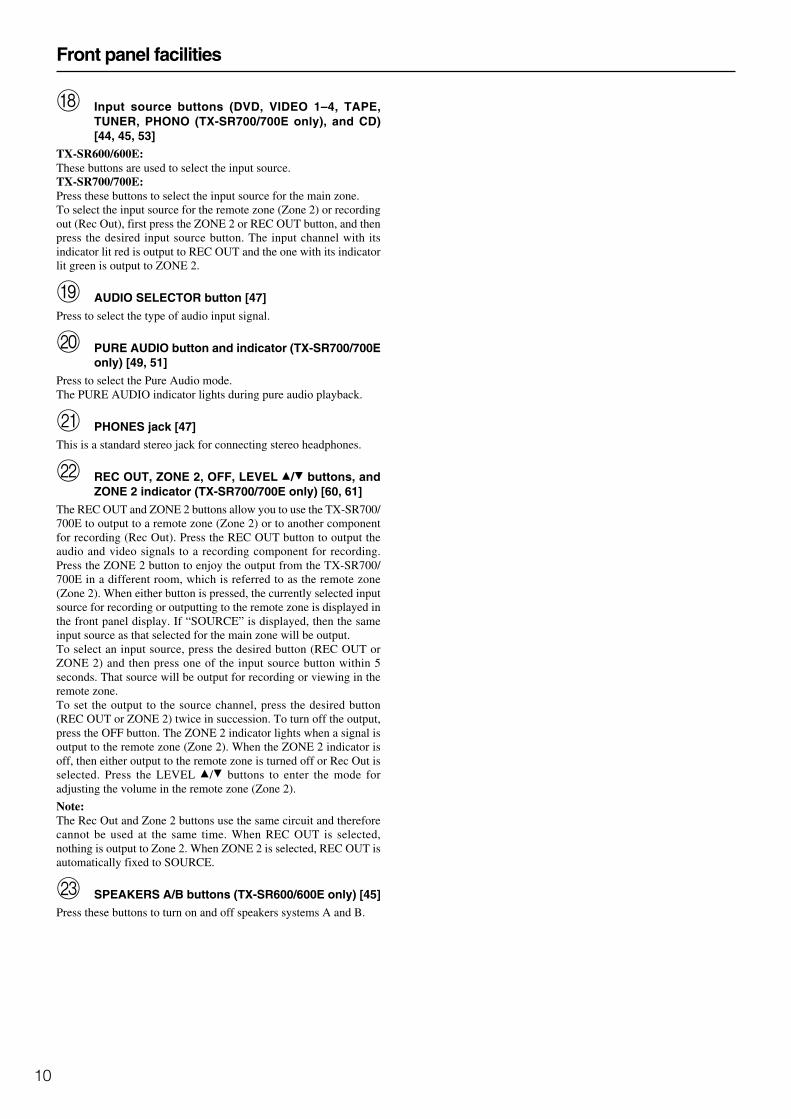
Input source buttons (DVD, VIDEO 1–4, TAPE,TUNER, PHONO (TX-SR700/700E only), and CD)[44, 45, 53]
TX-SR600/600E:These buttons are used to select the input source.TX-SR700/700E:Press these buttons to select the input source for the main zone.To select the input source for the remote zone (Zone 2) or recordingout (Rec Out), first press the ZONE 2 or REC OUT button, and thenpress the desired input source button. The input channel with itsindicator lit red is output to REC OUT and the one with its indicatorlit green is output to ZONE 2.
AUDIO SELECTOR button [47]
Press to select the type of audio input signal.
PURE AUDIO button and indicator (TX-SR700/700Eonly) [49, 51]
Press to select the Pure Audio mode.The PURE AUDIO indicator lights during pure audio playback.
PHONES jack [47]This is a standard stereo jack for connecting stereo headphones.
REC OUT, ZONE 2, OFF, LEVEL / buttons, andZONE 2 indicator (TX-SR700/700E only) [60, 61]
The REC OUT and ZONE 2 buttons allow you to use the TX-SR700/700E to output to a remote zone (Zone 2) or to another componentfor recording (Rec Out). Press the REC OUT button to output theaudio and video signals to a recording component for recording.Press the ZONE 2 button to enjoy the output from the TX-SR700/700E in a different room, which is referred to as the remote zone(Zone 2). When either button is pressed, the currently selected inputsource for recording or outputting to the remote zone is displayed inthe front panel display. If “SOURCE” is displayed, then the sameinput source as that selected for the main zone will be output.To select an input source, press the desired button (REC OUT orZONE 2) and then press one of the input source button within 5seconds. That source will be output for recording or viewing in theremote zone.To set the output to the source channel, press the desired button(REC OUT or ZONE 2) twice in succession. To turn off the output,press the OFF button. The ZONE 2 indicator lights when a signal isoutput to the remote zone (Zone 2). When the ZONE 2 indicator isoff, then either output to the remote zone is turned off or Rec Out isselected. Press the LEVEL / buttons to enter the mode foradjusting the volume in the remote zone (Zone 2).
Note:The Rec Out and Zone 2 buttons use the same circuit and thereforecannot be used at the same time. When REC OUT is selected,nothing is output to Zone 2. When ZONE 2 is selected, REC OUT isautomatically fixed to SOURCE.
SPEAKERS A/B buttons (TX-SR600/600E only) [45]Press these buttons to turn on and off speakers systems A and B.

11
Front panel display
Front panel facilities
MUTING indicator
Flashes when the mute function is turned on.
Listening mode or digital input format indicatorsOne of these indicators lights to show the format of the current inputsource. In addition, one of the listening mode indicators lights toindicate the current listening mode.
Tuning indicators
TUNED indicatorLights when a radio station is received.
AUTO indicatorLights when receiving FM broadcasts in the stereo mode. Turnsoff when placed into the monaural mode.
RDS indicator (European models only)Lights when an RDS station is received.
MEMORY indicatorLights when the MEMORY button is pressed to preset a radiostation.
FM STEREO indicatorLights when an FM broadcast station is received in stereo.
<TX-SR700E>
<TX-SR600E>
Multi function display
During normal operation, shows the current input source andvolume. When the FM or AM input is selected, shows the frequencyand preset number. When the DISPLAY button is pressed, shows thelistening mode and input source format. However, does not show thesource format when the FM or AM source is selected.
SLEEP indicatorLights when the sleep timer is turned on.
ZONE 2 indicator (TX-SR700/700E only)Lights when using the remote zone (Zone 2).
REC OUT indicator (TX-SR700/700E only)
Lights when recording the input source from one component toanother (Rec Out).
SPEAKERS A/B indicators (TX-SR600/600E only)Indicates which speaker system is currently in use.

12
Remote controller
SEND/LEARN indicatorLights red when signals are sent by the remote controller. It alsoflashes when a button is pressed when the battery power is low.
ON/STANDBY button [33]
ON: Press to turn on the TX-SR700/700E/600/600E.
STANDBY: Press to place the TX-SR700/700E/600/600E in thestandby state.
Be aware that pressing the STANDBY button only places the TX-SR700/700E/600/600E in standby and does not turn the powercompletely off.
SLEEP button [47]
Press to set the sleep function.The SLEEP button enables you to set the TX-SR700/700E/600/600E to turn off automatically after a specified time period.
MACRO 1, 2 button [73]Press to program or execute the macro function.
MODE buttons and indicators [44, 45, 64-66]Press to select the component to be operated by the remotecontroller. When a MODE button is pressed, it will light green for 8seconds. The selected MODE button will also light whenever anyother operation button is pressed.
RETURN button [36]
Press to enter the selected setting and return to the previous menu.
CH , DISC buttonPress to select a preset channel for the tuner (CH). [41]When the CD mode is selected, also press to select a disc whenoperating components with disc changers (DISC). [64]
CH SEL/TOP MENU buttonPress to select a speaker channel when adjusting the speaker level(CH SEL). [39]When the DVD mode is selected, press to display the menu screensof the DVD player (TOP MENU). [65]
AUDIO SEL/TV/VCR button [47]
Press to select the audio input signal. The setting changes from“Auto” to “Multich” (only if DVD is selected as the input source) to“Analog” and back each time this button is pressed.
LEVEL /ANGLE and LEVEL /SUBTITLE buttonsPress to adjust the volume of the speaker selected using the CH SELbutton (LEVEL / ). [39]Press the ANGLE button to select a camera angle when playing aDVD-Video with multiple angle playback.Press the SUBTITLE button to select a subtitle language whenplaying a DVD-Video. [65]
CD/TAPE/DVD/MD operation buttons [63-66]Press to operate other Onkyo components connected to the TX-SR700/700E/600/600E using the terminals.

13
Remote controller
INPUT SELECTOR buttons [44, 45, 53]Press to select an input source.Same as the input selector buttons on the front panel of the TX-SR700/700E/600/600E. The input source for each button is givenhere. DVD:DVD, CD:CD, V1:VIDEO1, V2:VIDEO2,V3:VIDEO3, V4:VIDEO4, V5:VIDEO5 (not used with the TX-SR700/700E/600/600E), TAP:TAPE, TUN:FM/AM, PH:PHONO(not used with the TX-SR600/600E).
Numeric key/Listening mode, SP A, SP B, CINEFLTR, DISPLAY, DIMMER buttons
1 to 9, +10, --/---, 0: For entering the number of a track. [64-66]
PURE A:
TX-SR600/600E: Not used with the TX-SR600/600E.
TX-SR700/700E: Press to select the Pure Audio mode. [51]
DIRECT, STEREO, SURR, ALL ST, DSP: You can select alistening mode. [51]
Note:During playback of a multichannel source, press the DIRECT buttonto turn off the tone control and the SURR button to turn on the tonecontrol.
SP A, SP B:
TX-SR600/600E: Switches between speakers A and B.
TX-SR700/700E: Not used with the TX-SR700/700E.
CINE FLTR: Depending on the listening mode, you can turn theCinemaFILTER function on or off. [52]
DISPLAY: For changing the display in the front display. [48]
DIMMER: Adjusts the display brightness.There are three settings available: normal, dark, and very dark.
LIGHT button (RC-482M only)Press to turn on and off the lights in the buttons of the remotecontroller.
SETUP button [36]Press to display the Setup Menu on the TV screen and in the display.Press again to exit the menu.
/ / / , ENTER button [36]When in the Setup Menu, press the upper and lower arrow buttons toselect an item, press the right and left arrow buttons to selectparameter values or modes, and press the ENTER button to advanceto the next item.
VOL button [44, 45]Press to adjust the volume.
TEST/MENU buttonThis button is used to set the speaker output levels. Use this button inconjunction with the LEVEL / and CH SEL buttons to calibratethe speakers levels without entering the Setup Menu. [39]
When the DVD mode is selected, press to display the DVD menu(MENU). [65]
MUTING button [48]Press to activate the mute function.
ZONE 2/SEARCH/ENTER button
When the DVD mode is selected, press to find the specific sectionon a DVD where you want to start playback (SEARCH). [65]
When in the RCVR mode, press to perform operations on the remotezone (ZONE 2) (not used with the TX-SR600/600E). [60]
When in the MD mode, press to enter the selected song (ENTER). [66]
14
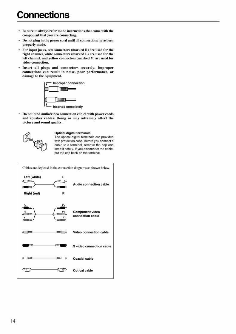
Connections• Be sure to always refer to the instructions that came with the
component that you are connecting.
• Do not plug in the power cord until all connections have beenproperly made.
• For input jacks, red connectors (marked R) are used for theright channel, white connectors (marked L) are used for theleft channel, and yellow connectors (marked V) are used forvideo connection.
• Insert all plugs and connectors securely. Improperconnections can result in noise, poor performance, ordamage to the equipment.
• Do not bind audio/video connection cables with power cordsand speaker cables. Doing so may adversely affect thepicture and sound quality.
Improper connection
Inserted completely
Optical digital terminalsThe optical digital terminals are providedwith protection caps. Before you connect acable to a terminal, remove the cap andkeep it safely. If you disconnect the cable,put the cap back on the terminal.
Audio connection cable
Component videoconnection cable
Video connection cable
S video connection cable
Coaxial cable
Optical cable
Left (white)
Right (red)
L
R
Cables are depicted in the connection diagrams as shown below.
PR
PB
Y
PR
PB
Y
15
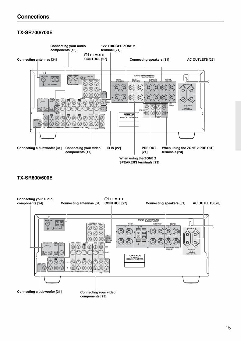
Connections
TX-SR700/700E
TX-SR600/600E
L
27122974
REMOTE CONTROL
CAUTION: SPEAKER IMPEDANCE6 OHMS MIN. /SPEAKER
ANTENNA
FM75
AM
COAXIAL
OPTICAL12
IN IN IN IN FRONT SURR CENTER
SUBWOOFERVIDEO 2 VIDEO 1
OUTOUT
DIGITAL INPUT VIDEO 2 DVD MONITOROUT
DVDTAPECD
SUBWOOFERPRE OUT
L
R
FRONTSPEAKERS
ZONE 2SPEAKERS
SURROUNDSPEAKERS
CENTERSPEAKER
R
L
R
L
FRONT SURROUND CENTER ZONE 2
SURROUNDBACK
R
L
R
L
PRE OUT
R
VIDEO 3
VIDEO 1
V12 VTRIGGEROUT
ZONE 2VIDEO 3
OPTICAL
COAXIALDIGITALINPUT
IN IN INOUTINDIGITALOUTPUT
IN
INPUT 1INPUT 2 OUTPUTCOMPONENT VIDEO
LRPHONO IN
PR
PB
Y
GND
OUT
OUT
SIRIN
SURROUND BACKSPEAKER
AC OUTLETS
SWITCHEDTOTAL 100W MAX.
AC 230-240 V50 Hz
AV RECEIVER
MODEL NO. TX-SR700E
L
27122965
REMOTE CONTROL
CAUTION: SPEAKER IMPEDANCE6 OHMS MIN. /SPEAKER
ANTENNA
FM75
AM
COAXIALOPTICAL12
IN IN IN IN FRONT SURR CENTER
SUBWOOFERVIDEO 2 VIDEO 1
OUT
DIGITAL INPUT DVD MONITOROUT
DVD
TAPECD
SUBWOOFERPRE OUT
L
R
FRONTSPEAKERS
SURROUNDSPEAKERS
CENTERSPEAKER
R
L
R
L
R
VIDEO 3
VIDEO 2VIDEO 3 VIDEO 1
VIDEOOPTICAL
ININ IN INDIGITALOUTPUT
IN
INPUT 1INPUT 2 OUTPUTCOMPONENT VIDEO
PR
PB
Y
OUT
OUT
A B
SURROUND BACKSPEAKER
DIGITALINPUT
L
R
R
L
S VIDEO
AC OUTLETS
AV RECEIVER
MODEL NO. TX-SR600E
SWITCHEDTOTAL 100W MAX.
AC 230-240 V50 Hz
Connecting your audiocomponents [16]
Connecting your videocomponents [17]
12V TRIGGER ZONE 2terminal [21]
PRE OUT[21]
IR IN [22]
When using the ZONE 2SPEAKERS terminals [23]
When using the ZONE 2 PRE OUTterminals [23]
AC OUTLETS [26] REMOTE
CONTROL [27] Connecting speakers [31]Connecting antennas [34]
Connecting your audiocomponents [24] Connecting antennas [34]
REMOTECONTROL [27] Connecting speakers [31] AC OUTLETS [26]
Connecting your videocomponents [25]
Connecting a subwoofer [31]
Connecting a subwoofer [31]

16
Connections (TX-SR700/700E)
Here is an explanation of typical ways to connect various components to the TX-SR700/700E. There are many ways that any one component canbe connected, and it is up to you to decide which method best fits your situation. The directions given here are only one option and should onlybe thought of as such. It is best to fully understand the nature of each connector and terminal as well as those of your components and theirfeatures to ascertain which method of connection is best.
: Signal flow
Connecting your audio components
Below is an example of how you can connect your audio componentsto the TX-SR700/700E. Refer to the diagram above for the followingconnection examples.
AUDIO IN/OUT
These are the analog audio inputs and outputs. There are seven audioinputs and three audio outputs on the rear panel. The audio inputsand outputs require RCA-type connectors.
DIGITAL INPUT/OUTPUT
On the rear panel of the TX-SR700/700E, there are one coaxialdigital input, two optical digital inputs, one coaxial digital output,and one optical digital output. To the digital inputs, connect CDplayers, LD players, DVD players, or other digital sourcecomponent. To the digital outputs, connect MD recorders, CDrecorders, DAT decks, or other similar components.
• Since an analog connection must be made when using REC OUTor ZONE 2, make sure that the connection to the input source isnot digital only, but analog as well.
• When using an optical input or output jack, always use an opticalfiber cable.
1. Connecting a compact disc player (CD)
Using an RCA audio cable, connect the output jacks of the compactdisc player to the CD audio jacks of the TX-SR700/700E. Make surethat you properly connect the left channel to the L jack and the rightchannel to the R jack.
If the compact disc player has a digital output, connect it to either theDIGITAL INPUT COAXIAL jack or the DIGITAL INPUTOPTICAL jack of the TX-SR700/700E depending on the type ofconnector on the compact disc player.
With the initial settings of the TX-SR700/700E, the CD inputsource is set for digital input at the OPTICAL 1 jack (OPT 1).If the digital connection is made to a different jack, this must bechanged at “Input Setup” → “Digital Input” (see page 53).
2. Connecting a turntable (PHONO)
Using an RCA audio cable, connect the output jacks of the turntableto the PHONO audio jacks of the TX-SR700/700E. Make sure thatyou properly connect the left channel to the L jack and the rightchannel to the R jack.
Note:The TX-SR700/700E is designed for use with moving magnetcartridges. For proper operation, connect a ground (or earth) wire tothe GND terminal. For some turntables, however, connecting theground wire may cause increased noise, and in such a case, a groundwire is not necessary and should not be connected.
3. Connecting a cassette tape deck, MD recorder, DAT deck, orCD recorder (TAPE)
Using RCA audio cables, connect the output jacks (PLAY) of thedevice to the TAPE IN audio jacks of the TX-SR700/700E andconnect the input jacks (REC) of the device to the TAPE OUT audiojacks of the TX-SR700/700E. Make sure that you properly connectthe left channels to the L jacks and the right channels to the R jacks.If the device has a digital output, connect it to either the DIGITALINPUT COAXIAL jack or the DIGITAL INPUT OPTICAL jack ofthe TX-SR700/700E depending on the type of connector on thedevice.
With the initial settings of the TX-SR700/700E, nothing isallocated as the digital input source for TAPE (----).If you connect the digital audio output, be sure to make the appropriatechanges at “Input Setup” → “Digital Input” (see page 53).
If the device has a digital input, connect it to the DIGITAL OUTPUT(OPTICAL or COAXIAL) jack of the TX-SR700/700E for digitalrecording of the signal from the digital input of the TX-SR700/700E.
Note:The output from the DIGITAL OUTPUT jack of the TX-SR700/700E is only the digital signal input to the DIGITAL INPUT jack.
L
ANTENNA
FM75
AM
COAXIAL
OPTICAL12
IN IN IN IN FRONT
VIDEO 2 VIDEO 1
OUTOUT
VIDEO 2 DVD
TAPECD
SUBWOOFERPRE OUT
L
RR
VIDEO 3
VIDEO 1VIDEO 3
OPTICAL
COAXIALDIGITALINPUT
IN IN INOUTINDIGITALOUTPUT
IN
INPUT 1INPUT 2COMPONEN
LRPHONO IN
GND
OUT
OUTDIGITAL INPUT
1. CD player (CD)
Digital audio output (optical)
L (white)
R (red)Analog audio output
Analog audio input
Analog audio output
L (white)
R (red)
L (white)
Ground wire (earth)
R (red)
Analog audio output
L (white)
R (red)
3. Cassette tape deck, MD recorder, DAT deck, or CD recorder (TAPE)
2. Turntable (PHONO)

17
Connections (TX-SR700/700E)
L
REMOTE CONTROL
ANTENNA
FM75
AM
COAXIAL
OPTICAL12
IN IN IN IN FRONT SURR CENTER
SUBWOOFERVIDEO 2 VIDEO 1
OUTOUT
DIGITAL INPUT VIDEO 2 DVD MONITOROUT
DVDTAPECD
SUBWOOFERPRE OUT
L
RR
VIDEO 3
VIDEO 1
V12 VTRIGGEOUT
ZONE 2VIDEO 3
OPTICAL
COAXIALDIGITALINPUT
IN IN INOUTINDIGITALOUTPUT
IN
INPUT 1INPUT 2 OUTPUTCOMPONENT VIDEO
LRPHONO IN
PR
PB
Y
GND
OUT
OUT
SIRIN
PR
PB
Y
4. DVD player (DVD)
S video output
R (red)
L (white)
R (red)
L (white)
Component video output
Video ouput
Digital audio output (coaxial)
Analog audio output (surround L/R)
Analog audio output (subwoofer)
Analog audio output (center)
Analog audio output (front L/R)
: Signal flow
Connecting a DVD Player with 5.1-Channel Output
Connecting your video components
Below is an example of how you can connect your video componentsto the TX-SR700/700E. Refer to the diagram above for the followingconnection examples.
COMPONENT VIDEO INPUT/OUTPUT
For DVD players or other devices that have component videoconnectors, the TX-SR700/700E has two banks of component videoinput connectors (Y, PB, PR) for direct component video input. TheTX-SR700/700E also has one bank of component video outputconnectors for direct component video output to the matrix decoderof a television, projector, or other display device. By sending thepure component video signal directly, the signal forgoes the extraprocessing that normally would degrade the image. The result isvastly increased image quality, with incredibly lifelike colors andcrisp detail.
• The signal that comes in from COMPONENT VIDEO INPUT isonly sent to COMPONENT VIDEO OUTPUT. Whenconnecting a video player to the COMPONENT VIDEO INPUTjacks, be sure to connect your television to the COMPONENTVIDEO OUTPUT jacks.
VIDEO IN/OUT
These are the video inputs and outputs. On the rear panel, there arefour video inputs and two video outputs and each one includes bothcomposite video and S video configurations.Connect VCRs, VTRs, LD players, DVD players, and other videocomponents to the video inputs. Connect VCRs, VTRs, and otherrecording components to the video outputs to make videorecordings.
• When connecting a VCR or other video component, make sureyou connect its audio and video leads to the same bank (e.g.,both to VIDEO 3).
• The VIDEO 4 inputs are located on the front panel.
The flow of the video signals is as follows:The signal that comes in from a VIDEO IN jack is sent to both theVIDEO OUT and S VIDEO OUT jacks. The signal that comes infrom a S VIDEO IN jack is sent to both the S VIDEO OUT andVIDEO OUT jacks. It is not necessary to make both video and Svideo connections.
Notes:
• If your video output device (e.g., television or projector) isconnected only to the MONITOR OUT VIDEO jack,MONITOR OUT S VIDEO jack, or both, and the video signalfrom the source component is input through the componentvideo connectors, no picture will appear. Video sources inputfrom the component video connectors can only be output fromthe component video connectors.
• For more information about the DIGITAL INPUT/OUTPUTjacks, see page 16.

18
Connections (TX-SR700/700E)
Connecting a DVD Player with 2-Channel (L/R) Audio Output
4. Connecting a DVD player (DVD)
Using an RCA video cable, connect the video output jack (composite)of the DVD player to the DVD VIDEO IN jack of the TX-SR700/700E. Or if the DVD player has an S video output jack, connect it tothe DVD S VIDEO IN jack with an S video cable. Or if the device hascomponent video outputs, connect them to the COMPONENTVIDEO INPUT 1 or 2 jacks on the TX-SR700/700E.
With the initial settings of the TX-SR700/700E, the DVD inputsource is set for the COMPONENT VIDEO INPUT 1 jacks.If you connect the DVD player to the COMPONENT VIDEOINPUT 2 jacks, this must be changed at “Input Setup” →“Component Video” (see page 54).
Using an RCA audio connection cable, connect the audio outputjacks of the DVD player to the DVD FRONT L/R jacks of the TX-SR700/700E. Make sure that you properly connect the left channelto the L jack and the right channel to the R jack.
If the device has a 5.1-channel output, connect the DVD FRONT L/R, SURR L/R, CENTER, and SUBWOOFER (5.1-channel input)jacks of the TX-SR700/700E to the 5.1-channel output jacks of theDVD player. Make sure that you properly connect the left channelsto the L jacks and the right channels to the R jacks.
If the device has a digital output, connect it to either the DIGITALINPUT COAXIAL jack or the DIGITAL INPUT OPTICAL jack ofthe TX-SR700/700E depending on the type of connector on theDVD player.
With the initial settings of the TX-SR700/700E, the DVD inputsource is set for digital input at the COAXIAL jack (COAX).If the digital connection is made at a different jack, this must bechanged at “Input Setup” → “Digital Input” (see page 53).
Note:If the DVD player has both 5.1-channel audio outputs and 2-channelaudio outputs, and you want to connect the DVD player only usingthe FRONT L/R jacks on the TX-SR700/700E, use the 2-channelaudio output jacks on the DVD player.
L
REMOTE CONTROL
ANTENNA
FM75
AM
COAXIAL
OPTICAL12
IN IN IN IN FRONT SURR CENTER
SUBWOOFERVIDEO 2 VIDEO 1
OUTOUT
DIGITAL INPUT VIDEO 2 DVD MONITOROUT
DVDTAPECD
SUBWOOFERPRE OUT
L
RR
VIDEO 3
VIDEO 1
V12 VTRIGGEOUT
ZONE 2VIDEO 3
OPTICAL
COAXIALDIGITALINPUT
IN IN INOUTINDIGITALOUTPUT
IN
INPUT 1INPUT 2 OUTPUTCOMPONENT VIDEO
LRPHONO IN
PR
PB
Y
GND
OUT
OUT
SIRIN
PR
PB
Y
4. DVD player (DVD)
S video output
R (red)
L (white)
Component video output
Video ouput
Digital audio output (coaxial)
Analog audio output
: Signal flow
19
Connections (TX-SR700/700E)
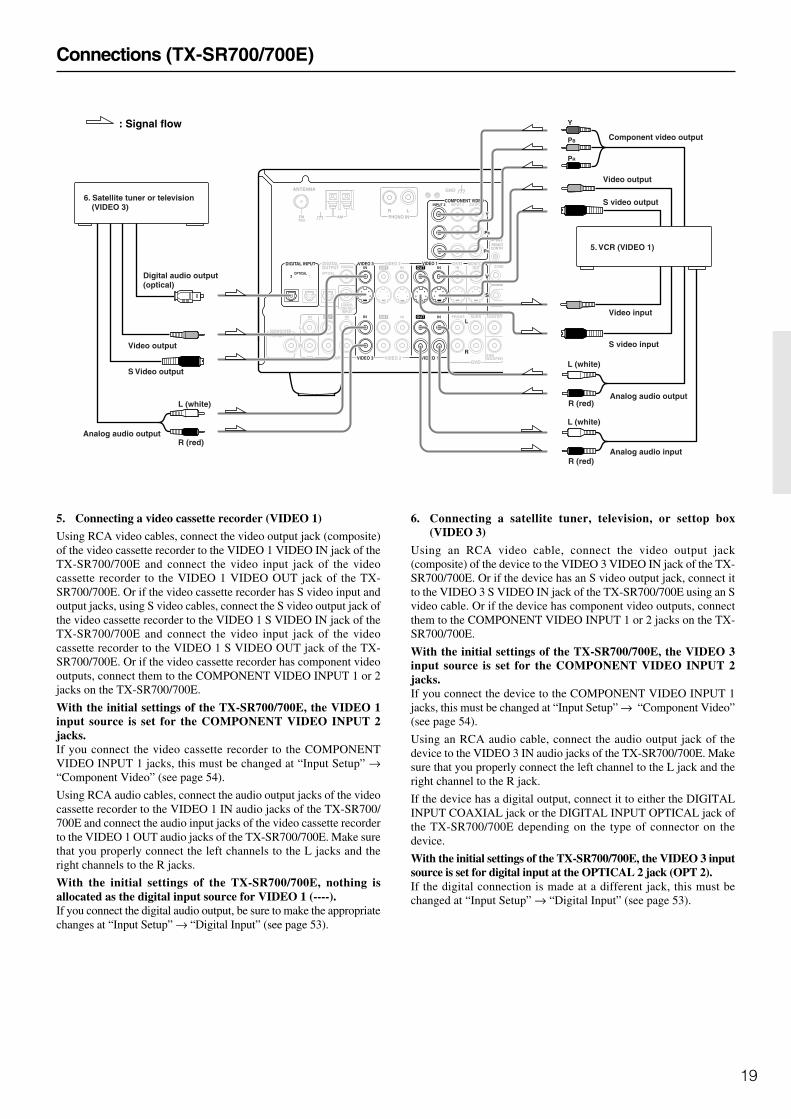
5. Connecting a video cassette recorder (VIDEO 1)
Using RCA video cables, connect the video output jack (composite)of the video cassette recorder to the VIDEO 1 VIDEO IN jack of theTX-SR700/700E and connect the video input jack of the videocassette recorder to the VIDEO 1 VIDEO OUT jack of the TX-SR700/700E. Or if the video cassette recorder has S video input andoutput jacks, using S video cables, connect the S video output jack ofthe video cassette recorder to the VIDEO 1 S VIDEO IN jack of theTX-SR700/700E and connect the video input jack of the videocassette recorder to the VIDEO 1 S VIDEO OUT jack of the TX-SR700/700E. Or if the video cassette recorder has component videooutputs, connect them to the COMPONENT VIDEO INPUT 1 or 2jacks on the TX-SR700/700E.
With the initial settings of the TX-SR700/700E, the VIDEO 1input source is set for the COMPONENT VIDEO INPUT 2jacks.If you connect the video cassette recorder to the COMPONENTVIDEO INPUT 1 jacks, this must be changed at “Input Setup” →“Component Video” (see page 54).
Using RCA audio cables, connect the audio output jacks of the videocassette recorder to the VIDEO 1 IN audio jacks of the TX-SR700/700E and connect the audio input jacks of the video cassette recorderto the VIDEO 1 OUT audio jacks of the TX-SR700/700E. Make surethat you properly connect the left channels to the L jacks and theright channels to the R jacks.
With the initial settings of the TX-SR700/700E, nothing isallocated as the digital input source for VIDEO 1 (----).If you connect the digital audio output, be sure to make the appropriatechanges at “Input Setup” → “Digital Input” (see page 53).
6. Connecting a satellite tuner, television, or settop box(VIDEO 3)
Using an RCA video cable, connect the video output jack(composite) of the device to the VIDEO 3 VIDEO IN jack of the TX-SR700/700E. Or if the device has an S video output jack, connect itto the VIDEO 3 S VIDEO IN jack of the TX-SR700/700E using an Svideo cable. Or if the device has component video outputs, connectthem to the COMPONENT VIDEO INPUT 1 or 2 jacks on the TX-SR700/700E.
With the initial settings of the TX-SR700/700E, the VIDEO 3input source is set for the COMPONENT VIDEO INPUT 2jacks.If you connect the device to the COMPONENT VIDEO INPUT 1jacks, this must be changed at “Input Setup” → “Component Video”(see page 54).
Using an RCA audio cable, connect the audio output jack of thedevice to the VIDEO 3 IN audio jacks of the TX-SR700/700E. Makesure that you properly connect the left channel to the L jack and theright channel to the R jack.
If the device has a digital output, connect it to either the DIGITALINPUT COAXIAL jack or the DIGITAL INPUT OPTICAL jack ofthe TX-SR700/700E depending on the type of connector on thedevice.
With the initial settings of the TX-SR700/700E, the VIDEO 3 inputsource is set for digital input at the OPTICAL 2 jack (OPT 2).If the digital connection is made at a different jack, this must bechanged at “Input Setup” → “Digital Input” (see page 53).
L
REMOTCONTRO
ANTENNA
FM75
AM
COAXIAL
OPTICAL12
IN IN IN IN FRONT SURR CENTER
SUBWOOFERVIDEO 2 VIDEO 1
OUTOUT
VIDEO 2 DVD MONITOROUT
DVDTAPECD
SUBWOOFERPRE OUT
L
RR
VIDEO 3
VIDEO 1
V
ZONEVIDEO 3
OPTICAL
COAXIALDIGITALINPUT
IN IN INOUTINDIGITALOUTPUT
IN
INPUT 1INPUT 2 OUTPUTCOMPONENT VIDEO
LRPHONO IN
PR
PB
Y
GND
OUT
OUT
S
DIGITAL INPUT
6. Satellite tuner or television(VIDEO 3)
5. VCR (VIDEO 1)
Component video output
PR
PB
Y
Video output
S video output
S Video output
Analog audio input
Analog audio output
L (white)
R (red)
L (white)
R (red)L (white)
R (red)Analog audio output
Video input
S video inputVideo output
Digital audio output(optical)
: Signal flow

20
Connections (TX-SR700/700E)
7. Connecting a DVD recorder or other digital video recordingdevice (VIDEO 2)
Using RCA video cables, connect the video output jack (composite)of the device to the VIDEO 2 VIDEO IN jack of the TX-SR700/700E and connect the video input jack of the device to the VIDEO 2VIDEO OUT jack of the TX-SR700/700E. Or if the device has Svideo input and output jacks, using S video cables, connect the Svideo output jack of the device to the VIDEO 2 S VIDEO IN jack ofthe TX-SR700/700E and connect the video input jack of the deviceto the VIDEO 2 S VIDEO OUT jack of the TX-SR700/700E. Or ifthe device has component video outputs, connect them to theCOMPONENT VIDEO INPUT 1 or 2 jacks on the TX-SR700/700E.
With the initial settings of the TX-SR700/700E, the VIDEO 2input source is set for the COMPONENT VIDEO INPUT 2jacks.If you connect the device to the COMPONENT VIDEO INPUT 1jacks, this must be changed at “Input Setup” → “Component Video”(see page 54).
Using RCA audio cables, connect the audio output jacks of thedevice to the VIDEO 2 IN audio jacks of the TX-SR700/700E andconnect the audio input jacks of the device to the VIDEO 2 OUTaudio jacks of the TX-SR700/700E. Make sure that you properlyconnect the left channels to the L jacks and the right channels to theR jacks.
If the device has a digital output, connect it to either the DIGITALINPUT COAXIAL jack or the DIGITAL INPUT OPTICAL jack ofthe TX-SR700/700E depending on the type of connector on thedevice.
With the initial settings of the TX-SR700/700E, nothing isallocated as the digital input source for VIDEO 2 (----).If you connect the digital audio output, be sure to make the appropriatechanges at “Input Setup” → “Digital Input” (see page 53).
If the device has a digital input, connect it to the DIGITAL OUTPUT(OPTICAL or COAXIAL) jack of the TX-SR700/700E for digitalrecording of the signal from the digital input of the TX-SR700/700E.
Note:The output from the DIGITAL OUTPUT jack of the TX-SR700/700E is only the digital signal input to the DIGITAL INPUT jack.
8. Connecting a television monitor or projector (MONITOROUT)
The TX-SR700/700E is equipped with a simple Y/C separate circuitand simple Y/C mixed circuit. Since both the signal from the SVIDEO and VIDEO inputs are output to the MONITOR OUT SVIDEO output, if the television or projector is equipped with an Svideo input, it is unnecessary to connect the video connectors. If it isequipped with only a video input, connect it to the MONITOR OUTVIDEO output.
Using an RCA video cable, connect the video input jack (composite)of the device to the MONITOR OUT VIDEO jack of the TX-SR700/700E. Or if the device has an S video input jack, connect it to theMONITOR OUT S VIDEO jack of the TX-SR700/700E using an Svideo cable. Or if the device has component video inputs, connectthem to the bank of COMPONENT VIDEO OUTPUT jacks on theTX-SR700/700E.
Note:Note that the Setup Menu will only be displayed on the monitorconnected to MONITOR OUT and not those connected to theCOMPONENT VIDEO OUTPUT jacks.
L
REMOTCONTRO
ANTENNA
FM75
AM
COAXIAL
OPTICAL12
IN IN IN IN FRONT SURR CENTER
SUBWOOFERVIDEO 2 VIDEO 1
OUTOUT
DIGITAL INPUT VIDEO 2 DVD MONITOROUT
DVDTAPECD
SUBWOOFERPRE OUT
L
RR
VIDEO 3
VIDEO 1
V
ZONEVIDEO 3
OPTICAL
COAXIALDIGITALINPUT
IN IN INOUTINDIGITALOUTPUT
IN
INPUT 1INPUT 2 OUTPUTCOMPONENT VIDEO
LRPHONO IN
PR
PB
Y
GND
OUT
OUT
S
8. TV monitor or projector(MONITOR OUT)
Component video input
S Video input
Video input
PR
PB
Y
7. DVD recorder, other digital video recording device (VIDEO 2)
R (red)
L (white)
R (red)
L (white)
Video input
S Video input
Video output
S Video output
Analog audio input
Analog audio output : Signal flow
21
Connections (TX-SR700/700E)
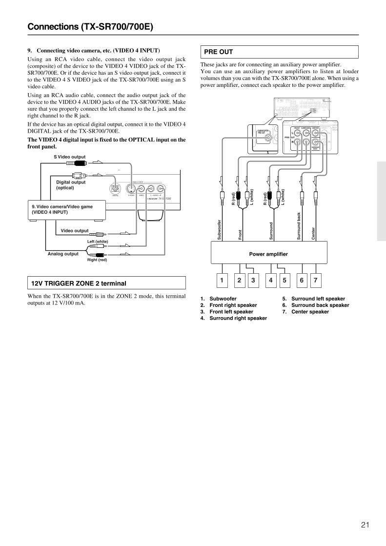
9. Connecting video camera, etc. (VIDEO 4 INPUT)
Using an RCA video cable, connect the video output jack(composite) of the device to the VIDEO 4 VIDEO jack of the TX-SR700/700E. Or if the device has an S video output jack, connect itto the VIDEO 4 S VIDEO jack of the TX-SR700/700E using an Svideo cable.
Using an RCA audio cable, connect the audio output jack of thedevice to the VIDEO 4 AUDIO jacks of the TX-SR700/700E. Makesure that you properly connect the left channel to the L jack and theright channel to the R jack.
If the device has an optical digital output, connect it to the VIDEO 4DIGITAL jack of the TX-SR700/700E.
The VIDEO 4 digital input is fixed to the OPTICAL input on thefront panel.
12V TRIGGER ZONE 2 terminal
When the TX-SR700/700E is in the ZONE 2 mode, this terminaloutputs at 12 V/100 mA.
Video output
Analog outputRight (red)
Left (white)
Digital output(optical)
9. Video camera/Video game(VIDEO 4 INPUT)
S Video output
L
27122974
REMOTE CONTROL
CAUTION: SPEAKER IMPEDANCE6 OHMS MIN. /SPEAKER
ANTENNA
FM75
AM
COAXIAL
OPTICAL12
IN IN IN IN FRONT SURR CENTER
SUBWOOFERVIDEO 2 VIDEO 1
OUTOUT
DIGITAL INPUT VIDEO 2 DVD MONITOROUT
DVDTAPECD
SUBWOOFERPRE OUT
L
R
FRONTSPEAKERS
ZONE 2SPEAKERS
SURROUNDSPEAKERS
CENTERSPEAKER
R
L
R
L
FRONT SURROUND CENTER ZONE 2
SURROUNDBACK
R
L
R
L
PRE OUT
R
VIDEO 3
VIDEO 1
V12 VTRIGGEROUT
ZONE 2VIDEO 3
OPTICAL
COAXIALDIGITALINPUT
IN IN INOUTINDIGITALOUTPUT
IN
INPUT 1INPUT 2 OUTPUTCOMPONENT VIDEO
LRPHONO IN
PR
PB
Y
GND
OUT
OUT
SIRIN
SURROUND BACKSPEAKER
AC OUTLETS
SWITCHEDTOTAL 100W MAX.
AC 230-240 V50 Hz
AV RECEIVER
MODEL NO. TX-SR700E
L
CD
SUBWOOFERPRE OUT
R
FRONT SURROUND CENTER ZONE 2
SURROUNDBACK
R
L
R
L
PRE OUT
SURROUBACKSPEAKE
Fro
nt
Su
rro
un
d
Su
rro
un
d b
ack
Cen
ter
Su
bw
oo
fer
R (
red
)
L (
wh
ite)
R (
red
)
L (
wh
ite)
7654321
PRE OUT
These jacks are for connecting an auxiliary power amplifier.You can use an auxiliary power amplifiers to listen at loudervolumes than you can with the TX-SR700/700E alone. When using apower amplifier, connect each speaker to the power amplifier.
1. Subwoofer2. Front right speaker3. Front left speaker4. Surround right speaker
5. Surround left speaker6. Surround back speaker7. Center speaker
Power amplifier

22
Operating components not reached by the remotecontroller signals (IR IN) (TX-SR700/700E only)
In order to use the remote controller to control the TX-SR700/700E from a remote location, you will need to prepare a multi-room kit (sold separately) such as one of those given below:
• Onkyo’s Multi-Room System kit (IR Remote ControllerExtension System)
• Multiroom A/V distribution and control system such as thosefrom Niles® and Xantech®
If the remote controller signal does not reach theTX-SR700/700E remote sensor
If the TX-SR700/700E is located inside a cabinet or other enclosurewhere the infrared rays from the remote controller cannot enter, thenoperation with the remote controller will not be possible. In such acase, it will be necessary to install a remote sensor at a locationoutside of the cabinet where the infrared rays from the controller canreach.With this connection, select “Main” at “Preference” → “IR INPosition” (see page 56).
The IR IN input allows you to control the TX-SR700/700E from theremote zone (Zone 2) with the remote controller even though theremote zone may be on the other side of the building from the mainzone. The diagram below shows how to make the proper connectionsfor the remote zone.With this connection, select “Zone 2” at “Preference” → “IR INPosition” (see page 56).
From connecting block
Connectingblock
TX-SR700/700E
Main room
: Signal flow
To IR IN
Zone 2 room
IR Receiver
Remote controller
IR IN
TX-SR700/700E
In the cabinet
Remote Controller
Connectingblock
IR Receiver
: Signal flow
REMOTE CONTROL
12 VTRIGGEROUT
ZONE 2
IRIN
Mini plug cable
TX-SR700/700E
Make the connections as shown below. Do not plug in anyequipment to the power outlet until all the connections are complete.

23
Connecting the remote zone (Zone 2) speakers(TX-SR700/700E only)
The TX-SR700/700E allows you to listen to two separate inputsources at the same time. This allows you to, for example, placespeakers in two different rooms so that two or more people can enjoytwo different kinds of music at the same time. The room where theTX-SR700/700E is actually located is referred to as the main roomwhile the separate room is referred to as the remote zone (Zone 2). Inaddition, the IR IN terminal of the TX-SR700/700E allows you tocontrol the TX-SR700/700E from the remote zone (Zone 2) with theremote controller even though the remote zone is physicallyseparated. The diagram below shows how to make the properconnections for the remote zone.
When using the ZONE 2 SPEAKERS terminals
If you are using a 5.1-channel speaker system in the main room, youcan connect the speakers for the remote zone (Zone 2) to the openZONE 2 SPEAKERS terminals.
Note:It is important to be aware of the speaker impedance (see page 31).
ZONE 2SPEAKERS
R
L
Remote Zone (Zone 2)Main Room
Zone 2Right
speaker
Zone 2Left
speaker
FRONT SURROUND CENTER ZONE 2
SURROUNDBACK
R
L
R
L
PRE OUT
Remote Zone (Zone 2)Main Room
Zone 2Right
speaker
Zone 2Left
speaker
Power amplifier
Left (white)
Right (red)
TX-SR700/700E
TX-SR700/700E
When using the ZONE 2 PRE OUT terminals
If you are using a 5.1-channel speaker system in the main room, youcan connect the amplifier for the remote zone (Zone 2) to the openZONE 2 PRE OUT terminals and connect the remote zone speakers.
24
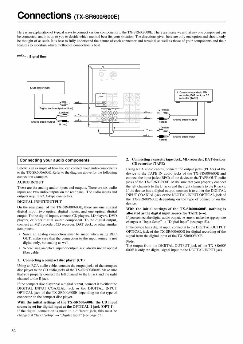
Connections (TX-SR600/600E)
Here is an explanation of typical ways to connect various components to the TX-SR600/600E. There are many ways that any one component canbe connected, and it is up to you to decide which method best fits your situation. The directions given here are only one option and should onlybe thought of as such. It is best to fully understand the nature of each connector and terminal as well as those of your components and theirfeatures to ascertain which method of connection is best.
: Signal flow
Connecting your audio components
Below is an example of how you can connect your audio componentsto the TX-SR600/600E. Refer to the diagram above for the followingconnection examples.
AUDIO IN/OUT
These are the analog audio inputs and outputs. There are six audioinputs and two audio outputs on the rear panel. The audio inputs andoutputs require RCA-type connectors.
DIGITAL INPUT/OUTPUT
On the rear panel of the TX-SR600/600E, there are one coaxialdigital input, two optical digital inputs, and one optical digitaloutput. To the digital inputs, connect CD players, LD players, DVDplayers, or other digital source component. To the digital output,connect an MD recorder, CD recorder, DAT deck, or other similarcomponent.
• Since an analog connection must be made when using RECOUT, make sure that the connection to the input source is notdigital only, but analog as well.
• When using an optical input or output jack, always use an opticalfiber cable.
1. Connecting a compact disc player (CD)
Using an RCA audio cable, connect the output jacks of the compactdisc player to the CD audio jacks of the TX-SR600/600E. Make surethat you properly connect the left channel to the L jack and the rightchannel to the R jack.
If the compact disc player has a digital output, connect it to either theDIGITAL INPUT COAXIAL jack or the DIGITAL INPUTOPTICAL jack of the TX-SR600/600E depending on the type ofconnector on the compact disc player.
With the initial settings of the TX-SR600/600E, the CD inputsource is set for digital input at the OPTICAL 1 jack (OPT 1).If the digital connection is made to a different jack, this must bechanged at “Input Setup” → “Digital Input” (see page 53).
2. Connecting a cassette tape deck, MD recorder, DAT deck, orCD recorder (TAPE)
Using RCA audio cables, connect the output jacks (PLAY) of thedevice to the TAPE IN audio jacks of the TX-SR600/600E andconnect the input jacks (REC) of the device to the TAPE OUT audiojacks of the TX-SR600/600E. Make sure that you properly connectthe left channels to the L jacks and the right channels to the R jacks.If the device has a digital output, connect it to either the DIGITALINPUT COAXIAL jack or the DIGITAL INPUT OPTICAL jack ofthe TX-SR600/600E depending on the type of connector on thedevice.
With the initial settings of the TX-SR600/600E, nothing isallocated as the digital input source for TAPE (----).If you connect the digital audio output, be sure to make the appropriatechanges at “Input Setup” → “Digital Input” (see page 53).
If the device has a digital input, connect it to the DIGITAL OUTPUTOPTICAL jack of the TX-SR600/600E for digital recording of thesignal from the digital input of the TX-SR600/600E.
Note:The output from the DIGITAL OUTPUT jack of the TX-SR600/600E is only the digital signal input to the DIGITAL INPUT jack.
L
ANTENNA
FM75
AM
COAXIALOPTICAL12
IN IN IN
VIDEO 2 VID
OUTTAPECD
SUBWOOFERPRE OUT
R
VIDEO 3
VIDEO 2VIDEO 3 VID
OPTICAL
ININDIGITALOUTPUT
IN OUT
OUTDIGITALINPUT
L
R
DIGITAL INPUT
1. CD player (CD)
Digital audio output (optical)
L (white)
R (red)Analog audio output
Analog audio input
Analog audio output
L (white)
R (red)
L (white)
R (red)
2. Cassette tape deck, MD recorder, DAT deck, or CD recorder (TAPE)
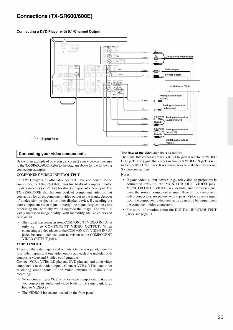
25
Connections (TX-SR600/600E)
Connecting your video components
Below is an example of how you can connect your video componentsto the TX-SR600/600E. Refer to the diagram above for the followingconnection examples.
COMPONENT VIDEO INPUT/OUTPUT
For DVD players or other devices that have component videoconnectors, the TX-SR600/600E has two banks of component videoinput connectors (Y, PB, PR) for direct component video input. TheTX-SR600/600E also has one bank of component video outputconnectors for direct component video output to the matrix decoderof a television, projector, or other display device. By sending thepure component video signal directly, the signal forgoes the extraprocessing that normally would degrade the image. The result isvastly increased image quality, with incredibly lifelike colors andcrisp detail.
• The signal that comes in from COMPONENT VIDEO INPUT isonly sent to COMPONENT VIDEO OUTPUT. Whenconnecting a video player to the COMPONENT VIDEO INPUTjacks, be sure to connect your television to the COMPONENTVIDEO OUTPUT jacks.
VIDEO IN/OUT
These are the video inputs and outputs. On the rear panel, there arefour video inputs and one video output and each one includes bothcomposite video and S video configurations.Connect VCRs, VTRs, LD players, DVD players, and other videocomponents to the video inputs. Connect VCRs, VTRs, and otherrecording components to the video outputs to make videorecordings.
• When connecting a VCR or other video component, make sureyou connect its audio and video leads to the same bank (e.g.,both to VIDEO 3).
• The VIDEO 4 inputs are located on the front panel.
The flow of the video signals is as follows:The signal that comes in from a VIDEO IN jack is sent to the VIDEOOUT jack. The signal that comes in from a S VIDEO IN jack is sentto the S VIDEO OUT jack. It is not necessary to make both video andS video connections.
Notes:
• If your video output device (e.g., television or projector) isconnected only to the MONITOR OUT VIDEO jack,MONITOR OUT S VIDEO jack, or both, and the video signalfrom the source component is input through the componentvideo connectors, no picture will appear. Video sources inputfrom the component video connectors can only be output fromthe component video connectors.
• For more information about the DIGITAL INPUT/OUTPUTjacks, see page 24.
L
REMOTE CONTROL
ANTENNA
FM75
AM
COAXIALOPTICAL12
IN IN IN IN FRONT SURR CENTER
SUBWOOFERVIDEO 2 VIDEO 1
OUT
DIGITAL INPUT DVD MONITOROUT
DVD
TAPECD
SUBWOOFERPRE OUT
L
RR
VIDEO 3
VIDEO 2VIDEO 3 VIDEO 1
VIDEOOPTICAL
ININ IN INDIGITALOUTPUT
IN
INPUT 1INPUT 2 OUTPUTCOMPONENT VIDEO
PR
PB
Y
OUT
OUTDIGITALINPUT
L
R
S VIDEO
PR
PB
Y
3. DVD player (DVD)
S video output
R (red)
L (white)
R (red)
L (white)
Component video output
Video ouput
Digital audio output (coaxial)
Analog audio output (surround L/R)
Analog audio output (subwoofer)
Analog audio output (center)
Analog audio output (front L/R)
: Signal flow
Connecting a DVD Player with 5.1-Channel Output
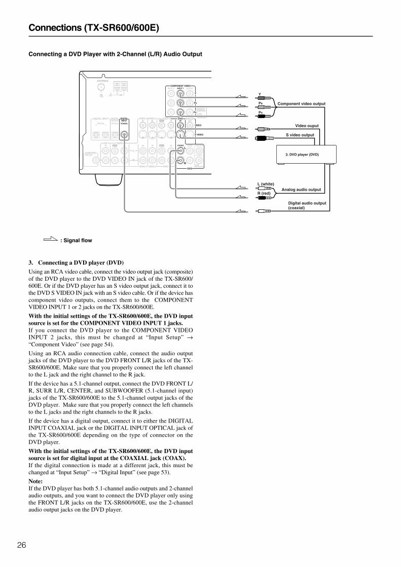
26
3. Connecting a DVD player (DVD)
Using an RCA video cable, connect the video output jack (composite)of the DVD player to the DVD VIDEO IN jack of the TX-SR600/600E. Or if the DVD player has an S video output jack, connect it tothe DVD S VIDEO IN jack with an S video cable. Or if the device hascomponent video outputs, connect them to the COMPONENTVIDEO INPUT 1 or 2 jacks on the TX-SR600/600E.
With the initial settings of the TX-SR600/600E, the DVD inputsource is set for the COMPONENT VIDEO INPUT 1 jacks.If you connect the DVD player to the COMPONENT VIDEOINPUT 2 jacks, this must be changed at “Input Setup” →“Component Video” (see page 54).
Using an RCA audio connection cable, connect the audio outputjacks of the DVD player to the DVD FRONT L/R jacks of the TX-SR600/600E. Make sure that you properly connect the left channelto the L jack and the right channel to the R jack.
If the device has a 5.1-channel output, connect the DVD FRONT L/R, SURR L/R, CENTER, and SUBWOOFER (5.1-channel input)jacks of the TX-SR600/600E to the 5.1-channel output jacks of theDVD player. Make sure that you properly connect the left channelsto the L jacks and the right channels to the R jacks.
If the device has a digital output, connect it to either the DIGITALINPUT COAXIAL jack or the DIGITAL INPUT OPTICAL jack ofthe TX-SR600/600E depending on the type of connector on theDVD player.
With the initial settings of the TX-SR600/600E, the DVD inputsource is set for digital input at the COAXIAL jack (COAX).If the digital connection is made at a different jack, this must bechanged at “Input Setup” → “Digital Input” (see page 53).
Note:If the DVD player has both 5.1-channel audio outputs and 2-channelaudio outputs, and you want to connect the DVD player only usingthe FRONT L/R jacks on the TX-SR600/600E, use the 2-channelaudio output jacks on the DVD player.
Connections (TX-SR600/600E)
Connecting a DVD Player with 2-Channel (L/R) Audio Output
: Signal flow
L
REMOTE CONTROL
ANTENNA
FM75
AM
COAXIALOPTICAL12
IN IN IN IN FRONT SURR CENTER
SUBWOOFERVIDEO 2 VIDEO 1
OUT
DIGITAL INPUT DVD MONITOROUT
DVD
TAPECD
SUBWOOFERPRE OUT
L
RR
VIDEO 3
VIDEO 2VIDEO 3 VIDEO 1
VIDEOOPTICAL
ININ IN INDIGITALOUTPUT
IN
INPUT 1INPUT 2 OUTPUTCOMPONENT VIDEO
PR
PB
Y
OUT
OUTDIGITALINPUT
L
R
S VIDEO
PR
PB
Y
3. DVD player (DVD)
S video output
R (red)
L (white)
Component video output
Video ouput
Digital audio output (coaxial)
Analog audio output

27
Connections (TX-SR600/600E)
4. Connecting a video cassette recorder (VIDEO 1)
Using RCA video cables, connect the video output jack (composite)of the video cassette recorder to the VIDEO 1 VIDEO IN jack of theTX-SR600/600E and connect the video input jack of the videocassette recorder to the VIDEO 1 VIDEO OUT jack of the TX-SR600/600E. Or if the video cassette recorder has S video input andoutput jacks, using S video cables, connect the S video output jack ofthe video cassette recorder to the VIDEO 1 S VIDEO IN jack of theTX-SR600/600E and connect the video input jack of the videocassette redorder to the VIDEO 1 S VIDEO OUT jack of the TX-SR600/600E. Or if the video cassette recorder has component videooutputs, connect them to the COMPONENT VIDEO INPUT 1 or 2jacks on the TX-SR600/600E.
With the initial settings of the TX-SR600/600E, the VIDEO 1input source is set for the COMPONENT VIDEO INPUT 2jacks.If you connect the video cassette recorder to the COMPONENTVIDEO INPUT 1 jacks, this must be changed at “Input Setup” →“Component Video” (see page 54).
Using RCA audio cables, connect the audio output jacks of the videocassette recorder to the VIDEO 1 IN audio jacks of the TX-SR600/600E and connect the audio input jacks of the video cassette recorderto the VIDEO 1 OUT audio jacks of the TX-SR600/600E. Make surethat you properly connect the left channels to the L jacks and theright channels to the R jacks.
With the initial settings of the TX-SR600/600E, nothing isallocated as the digital input source for VIDEO 1 (----).If you connect the digital audio output, be sure to make the appropriatechanges at “Input Setup” → “Digital Input” (see page 53).
5. Connecting a satellite tuner, television, or settop box(VIDEO 2 or 3)
Using an RCA video cable, connect the video output jack(composite) of the device to the VIDEO 2 (or 3) VIDEO IN jack ofthe TX-SR600/600E. Or if the device has an S video output jack,connect it to the VIDEO 2 (or 3) S VIDEO IN jack of the TX-SR600/600E using an S video cable. Or if the device has component videooutputs, connect them to the COMPONENT VIDEO INPUT 1 or 2jacks on the TX-SR600/600E.
With the initial settings of the TX-SR600/600E, the VIDEO 2and 3 input sources are set for the COMPONENT VIDEOINPUT 2 jacks.If you connect the device to the COMPONENT VIDEO INPUT 1jacks, this must be changed at “Input Setup” → “Component Video”(see page 54).
Using an RCA audio cable, connect the audio output jack of thedevice to the VIDEO 2 (or 3) IN audio jacks of the TX-SR600/600E.Make sure that you properly connect the left channel to the L jackand the right channel to the R jack.
If the device has a digital output, connect it to either the DIGITALINPUT COAXIAL jack or the DIGITAL INPUT OPTICAL jack ofthe TX-SR600/600E depending on the type of connector on thedevice.
With the initial settings of the TX-SR600/600E, the VIDEO 3input source is set for digital input at the OPTICAL 2 jack (OPT2).If the digital connection is made at a different jack, this must bechanged at Input Setup → Digital Input (see page 53).
With the initial settings of the TX-SR600/600E, nothing isallocated as the digital input source for VIDEO 2 (----).If you connect the digital audio output, be sure to make the appropriatechanges at “Input Setup” → “Digital Input” (see page 53).
: Signal flow
L
REMOTCONTRO
ANTENNA
FM75
AM
COAXIALOPTICAL12
IN IN IN IN FRONT SURR CENTER
SUBWOOFERVIDEO 2 VIDEO 1
OUT
DVD MONITOROUT
DVD
TAPECD
SUBWOOFERPRE OUT
L
RR
VIDEO 3
VIDEO 2VIDEO 3 VIDEO 1
VIDEOOPTICAL
ININ IN INDIGITALOUTPUT
IN
INPUT 1INPUT 2 OUTPUTCOMPONENT VIDEO
PR
PB
Y
OUT
OUTDIGITALINPUT
L
R
S VIDEO
DIGITAL INPUT
5. Satellite tuner or television(VIDEO 2/3)
4. VCR (VIDEO 1)
Component video output
PR
PB
Y
Video output
S video output
Video input
S video inputVideo output
S Video output
Analog audio input
Analog audio output
L (white)
R (red)
L (white)
R (red)L (white)
R (red)Analog audio output
Digital audio output(optical)
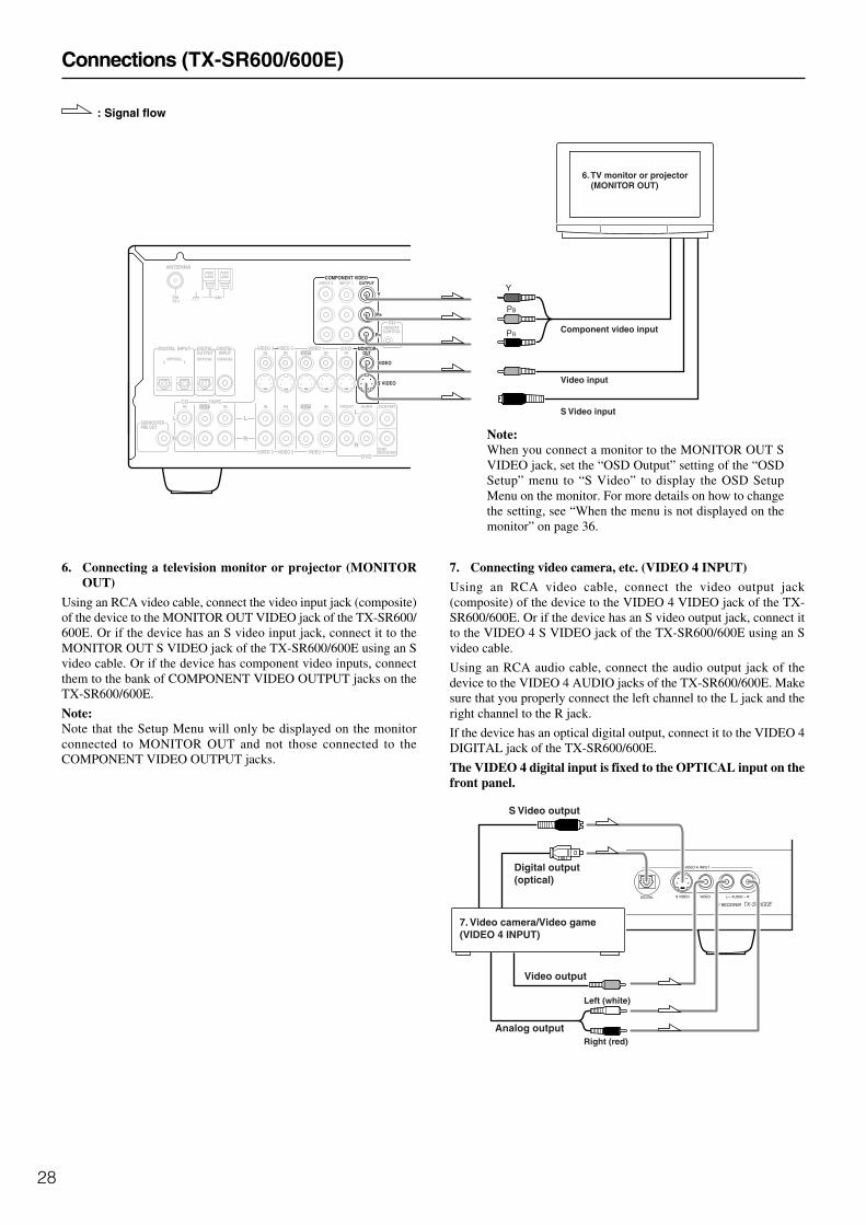
28
Connections (TX-SR600/600E)
6. Connecting a television monitor or projector (MONITOROUT)
Using an RCA video cable, connect the video input jack (composite)of the device to the MONITOR OUT VIDEO jack of the TX-SR600/600E. Or if the device has an S video input jack, connect it to theMONITOR OUT S VIDEO jack of the TX-SR600/600E using an Svideo cable. Or if the device has component video inputs, connectthem to the bank of COMPONENT VIDEO OUTPUT jacks on theTX-SR600/600E.
Note:Note that the Setup Menu will only be displayed on the monitorconnected to MONITOR OUT and not those connected to theCOMPONENT VIDEO OUTPUT jacks.
Video output
Analog outputRight (red)
Left (white)
Digital output(optical)
7. Video camera/Video game(VIDEO 4 INPUT)
S Video output
7. Connecting video camera, etc. (VIDEO 4 INPUT)
Using an RCA video cable, connect the video output jack(composite) of the device to the VIDEO 4 VIDEO jack of the TX-SR600/600E. Or if the device has an S video output jack, connect itto the VIDEO 4 S VIDEO jack of the TX-SR600/600E using an Svideo cable.
Using an RCA audio cable, connect the audio output jack of thedevice to the VIDEO 4 AUDIO jacks of the TX-SR600/600E. Makesure that you properly connect the left channel to the L jack and theright channel to the R jack.
If the device has an optical digital output, connect it to the VIDEO 4DIGITAL jack of the TX-SR600/600E.
The VIDEO 4 digital input is fixed to the OPTICAL input on thefront panel.
L
REMOTE CONTROL
ANTENNA
FM75
AM
COAXIALOPTICAL12
IN IN IN IN FRONT SURR CENTER
SUBWOOFERVIDEO 2 VIDEO 1
OUT
DIGITAL INPUT DVD MONITOROUT
DVD
TAPECD
SUBWOOFERPRE OUT
L
RR
VIDEO 3
VIDEO 2VIDEO 3 VIDEO 1
VIDEOOPTICAL
ININ IN INDIGITALOUTPUT
IN
INPUT 1INPUT 2 OUTPUTCOMPONENT VIDEO
PR
PB
Y
OUT
OUTDIGITALINPUT
L
R
S VIDEO
6. TV monitor or projector(MONITOR OUT)
Component video input
S Video input
Video input
PR
PB
Y
: Signal flow
Note:When you connect a monitor to the MONITOR OUT SVIDEO jack, set the “OSD Output” setting of the “OSDSetup” menu to “S Video” to display the OSD SetupMenu on the monitor. For more details on how to changethe setting, see “When the menu is not displayed on themonitor” on page 36.
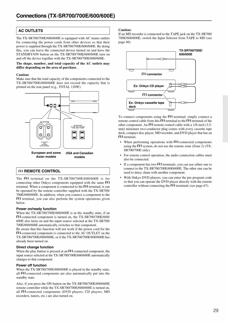
29
Caution:If an MD recorder is connected to the TAPE jack on the TX-SR700/700E/600/600E, switch the Input Selector from TAPE to MD (seepage 46).
To connect components using the terminal, simply connect aremote control cable from this terminal to the terminal of theother component. An remote control cable with a 1/8-inch (3.5-mm) miniature two-conductor plug comes with every cassette tapedeck, compact disc player, MD recorder, and DVD player that has an
terminal.
• When performing operations with -connected componentsusing the system, do not use the remote zone (Zone 2) (TX-SR700/700E only).
• For remote control operation, the audio connection cables mustalso be connected.
• If a component has two terminals, you can use either one toconnect to the TX-SR700/700E/600/600E. The other one can beused to daisy chain with another component.
• With Onkyo DVD players, you can enter the pre-program codeso that you can operate the DVD player directly with the remotecontroller without connecting the terminals (see page 67).
Connections (TX-SR700/700E/600/600E)
AC OUTLETS
The TX-SR700/700E/600/600E is equipped with AC mains outletsfor connecting the power cords from other devices so that theirpower is supplied through the TX-SR700/700E/600/600E. By doingthis, you can leave the connected device turned on and have theSTANDBY/ON button on the TX-SR700/700E/600/600E turn onand off the device together with the TX-SR700/700E/600/600E.
The shape, number, and total capacity of the AC outlets maydiffer depending on the area of purchase.
Caution:Make sure that the total capacity of the components connected to theTX-SR700/700E/600/600E does not exceed the capacity that isprinted on the rear panel (e.g., TOTAL 120W).
REMOTE CONTROL
The terminal on the TX-SR700/700E/600/600E is forconnecting other Onkyo components equipped with the same terminal. When a component is connected to the terminal, it canbe operated by the remote controller supplied with the TX-SR700/700E/600/600E. In addition, when you connect a component to the
terminal, you can also perform the system operations givenbelow.
Power on/ready functionWhen the TX-SR700/700E/600/600E is in the standby state, if an
-connected component is turned on, the TX-SR700/700E/600/600E also turns on and the input source selected at the TX-SR700/700E/600/600E automatically switches to that component.Be aware that this function will not work if the power cord for the
-connected component is connected to the AC OUTLET on theTX-SR700/700E/600/600E, or if the TX-SR700/700E/600/600E hasalready been turned on.
Direct change functionWhen the play button is pressed at an -connected component, theinput source selected at the TX-SR700/700E/600/600E automaticallychanges to that component.
Power off functionWhen the TX-SR700/700E/600/600E is placed in the standby state,all -connected components are also automatically put into thestandby state.
Also, if you press the ON button on the TX-SR700/700E/600/600Eremote controller while the TX-SR700/700E/600/600E is turned on,all -connected components (DVD players, CD players, MDrecorders, tuners, etc.) are also turned on.
AC OUTLETS
SWITCHEDTOTAL 100W MAX.
AC 230-240 V50 Hz
AC OUTLETSAC 120 V 60 Hz SWITCHED
TOTAL 120 W 1 A MAX.
European and someAsian models
USA and Canadianmodels
Ex: Onkyo CD player
TX-SR700/700E/600/600E
connector
Ex: Onkyo cassette tapedeck
connector
REMOTE CONTROL
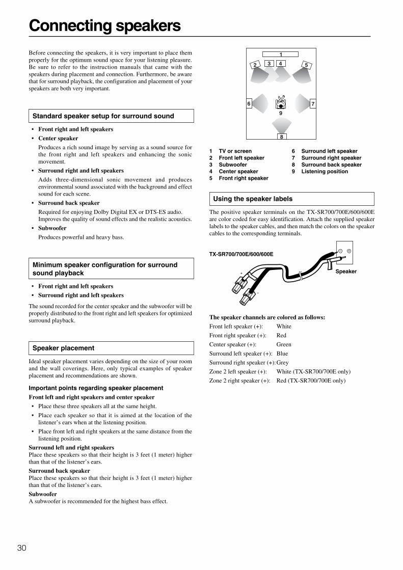
30
Before connecting the speakers, it is very important to place themproperly for the optimum sound space for your listening pleasure.Be sure to refer to the instruction manuals that came with thespeakers during placement and connection. Furthermore, be awarethat for surround playback, the configuration and placement of yourspeakers are both very important.
Standard speaker setup for surround sound
• Front right and left speakers
• Center speaker
Produces a rich sound image by serving as a sound source forthe front right and left speakers and enhancing the sonicmovement.
• Surround right and left speakers
Adds three-dimensional sonic movement and producesenvironmental sound associated with the background and effectsound for each scene.
• Surround back speaker
Required for enjoying Dolby Digital EX or DTS-ES audio.Improves the quality of sound effects and the realistic acoustics.
• Subwoofer
Produces powerful and heavy bass.
Minimum speaker configuration for surroundsound playback
• Front right and left speakers
• Surround right and left speakers
The sound recorded for the center speaker and the subwoofer will beproperly distributed to the front right and left speakers for optimizedsurround playback.
Speaker placement
Ideal speaker placement varies depending on the size of your roomand the wall coverings. Here, only typical examples of speakerplacement and recommendations are shown.
Important points regarding speaker placementFront left and right speakers and center speaker
• Place these three speakers all at the same height.
• Place each speaker so that it is aimed at the location of thelistener’s ears when at the listening position.
• Place front left and right speakers at the same distance from thelistening position.
Surround left and right speakersPlace these speakers so that their height is 3 feet (1 meter) higherthan that of the listener’s ears.
Surround back speakerPlace these speakers so that their height is 3 feet (1 meter) higherthan that of the listener’s ears.
SubwooferA subwoofer is recommended for the highest bass effect.
Connecting speakers
2 3 4 5
6 7
9
1
8
1 TV or screen2 Front left speaker3 Subwoofer4 Center speaker5 Front right speaker
6 Surround left speaker7 Surround right speaker8 Surround back speaker9 Listening position
Using the speaker labels
The positive speaker terminals on the TX-SR700/700E/600/600Eare color coded for easy identification. Attach the supplied speakerlabels to the speaker cables, and then match the colors on the speakercables to the corresponding terminals.
The speaker channels are colored as follows:
Front left speaker (+): White
Front right speaker (+): Red
Center speaker (+): Green
Surround left speaker (+): Blue
Surround right speaker (+):Grey
Zone 2 left speaker (+): White (TX-SR700/700E only)
Zone 2 right speaker (+): Red (TX-SR700/700E only)
TX-SR700/700E/600/600E
Speaker

31
SPEAKER B (TX-SR600/600E only)
1. Strip away approx. 3/8 inch (10 mm)of the wire insulation.
2. Twist the wire ends tightly together.
3. Press the lever to open the terminal.
4. Insert the exposed wire end.
5. Release the lever to close theterminal. Leave some of the exposedwire showing outside the terminal.
Connecting a subwoofer
Use the SUBWOOFER PRE OUT jack to connect a subwoofer witha built-in power amplifier. If your subwoofer does not have a built-inamplifier, connect an amplifier to the SUBWOOFER PRE OUT jackand the subwoofer to the amplifier.
Connecting to the SPEAKERS B terminals(TX-SR600/600E only)
If you require an additional set of front speakers (left and right), suchas for use in another room, connect them to the FRONT SPEAKERSB inputs.
Connecting speakers
Connecting speakers
After determining the layout of your speaker system, it is nownecessary to connect the speakers correctly to your TX-SR700/700E/600/600E.
Caution:
• Be sure to connect the positive (+) and negative (–) cables for thespeakers properly. If they are mixed up, the left and right signalswill be reversed and the audio will sound unnatural.
• Do not connect more than one speaker cable to one speakerterminal. Doing so may damage the TX-SR700/700E/600/600E.
• When you listen to surround audio or select Multichannel, besure to turn on SPEAKERS A.
• Connect only speakers with an impedance between 6 and 16Ω to the TX-SR700/700E/600/600E. Connecting speakerswith an impedance lower than 6 Ω may damage theamplifier.
• Even if you are using only one speaker or listening to monaural(mono) sound, never connect a single speaker in parallel to boththe right and left-channel terminals.
• To prevent damage to circuitry, never short-circuit the positive(+) and negative (–) speaker wires.
Connecting the speaker cable
1. Strip away approx. 5/8 inch (15 mm)of the wire insulation.
2. Twist the wire ends tightly together.
3. Unscrew the speaker terminal cap.
4. Insert the exposed wire end.
5. Screw down the speaker terminalcap.
R
L
R
L
SPEAKERS+–
+–
R
L
R
L
SPEAKERS+–
+–
NO!
5/8"(15mm)
3/8"(10mm)
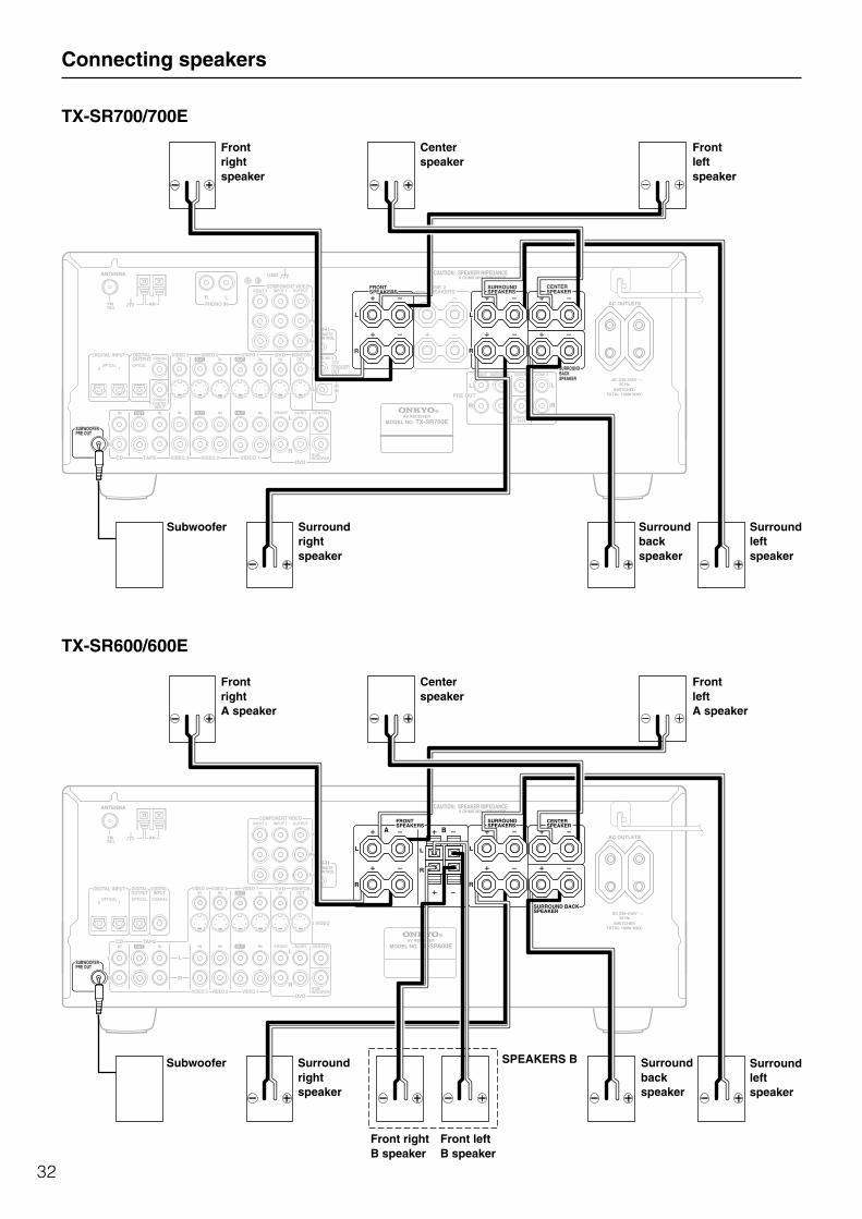
32
Connecting speakers
L
27122974
REMOTE CONTROL
CAUTION: SPEAKER IMPEDANCE6 OHMS MIN. /SPEAKER
ANTENNA
FM75
AM
COAXIAL
OPTICAL12
IN IN IN IN FRONT SURR CENTER
SUBWOOFERVIDEO 2 VIDEO 1
OUTOUT
DIGITAL INPUT VIDEO 2 DVD MONITOROUT
DVDTAPECD
SUBWOOFERPRE OUT
L
R
FRONTSPEAKERS
ZONE 2SPEAKERS
SURROUNDSPEAKERS
CENTERSPEAKER
R
L
R
L
FRONT SURROUND CENTER ZONE 2
SURROUNDBACK
R
L
R
L
PRE OUT
R
VIDEO 3
VIDEO 1
V12 VTRIGGEROUT
ZONE 2VIDEO 3
OPTICAL
COAXIALDIGITALINPUT
IN IN INOUTINDIGITALOUTPUT
IN
INPUT 1INPUT 2 OUTPUTCOMPONENT VIDEO
LRPHONO IN
PR
PB
Y
GND
OUT
OUT
SIRIN
SURROUND BACKSPEAKER
AC OUTLETS
SWITCHEDTOTAL 100W MAX.
AC 230-240 V50 Hz
AV RECEIVER
MODEL NO. TX-SR700E
TX-SR700/700E
TX-SR600/600E
L
27122965
REMOTE CONTROL
CAUTION: SPEAKER IMPEDANCE6 OHMS MIN. /SPEAKER
ANTENNA
FM75
AM
COAXIALOPTICAL12
IN IN IN IN FRONT SURR CENTER
SUBWOOFERVIDEO 2 VIDEO 1
OUT
DIGITAL INPUT DVD MONITOROUT
DVD
TAPECD
SUBWOOFERPRE OUT
L
R
FRONTSPEAKERS
SURROUNDSPEAKERS
CENTERSPEAKER
R
L
R
L
R
VIDEO 3
VIDEO 2VIDEO 3 VIDEO 1
VIDEOOPTICAL
ININ IN INDIGITALOUTPUT
IN
INPUT 1INPUT 2 OUTPUTCOMPONENT VIDEO
PR
PB
Y
OUT
OUT
A B
SURROUND BACKSPEAKER
DIGITALINPUT
L
R
R
L
S VIDEO
AC OUTLETS
AV RECEIVER
MODEL NO. TX-SR600E
SWITCHEDTOTAL 100W MAX.
AC 230-240 V50 Hz
Frontleftspeaker
Frontrightspeaker
Surroundleftspeaker
Surroundrightspeaker
Centerspeaker
Surroundbackspeaker
FrontrightA speaker
Centerspeaker
FrontleftA speaker
Surroundrightspeaker
Subwoofer
Front rightB speaker
Front leftB speaker
SPEAKERS B Surroundbackspeaker
Surroundleftspeaker
Subwoofer

33
ON
RCVR
STANDBY
POWER
STANDBY/ON
• Before you plug in the TX-SR700/700E/600/600E, confirm thatall connections have been made properly.
• Turning on the power may cause a momentary power surge,which might interfere with other electrical equipment on thesame circuit, such as computers. If this happens, use a wall outleton a different circuit.
(All models other than USA and Canadian models)
• The TX-SR700/700E/600/600E is shipped with the main power(POWER) switch in the on position ( ON). When the powercord is plugged in for the first time, the TX-SR700/700E/600/600E will automatically enter the standby state and theSTANDBY indicator will light (same condition after step 2below).
Turning on the power
1. Plug the power cord into an AC wall outlet.
(USA and Canadian models)The STANDBY indicator will light up.
(All models other than USA and Canadian models)Press the POWER switch to set the TX-SR700/700E/600/600E to standby state.The STANDBY indicator will light up.
2. Press the STANDBY/ON button to turn on the TX-SR700/700E/600/600E.The display will light up and the STANDBY indicator will turnoff.If you press the STANDBY/ON button again, the receiverreturns to standby state.
Connecting the power
STANDBY indicator
To wall outlet
Turning on the power from the remote controller
Before you can use the remote controller, you must perform step 1above and place the TX-SR700/700E/600/600E in the standby state.
1. Press the RCVR MODE button.The RCVR MODE button lights green.
2. Press the ON button to turn on theTX-SR700/700E/600/600E (take it outof the standby state).To return the TX-SR700/700E/600/600E tothe standby state, press the STANDBYbutton.
Turn off
Memory preservation (Other than USA and Canadianmodels)The TX-SR700/700E/600/600E does not require memorypreservation batteries. A built-in memory backup systempreserves the contents of memory (e.g., speaker settings andsurround settings) during power failures and even when thepower is turned off with the POWER switch. The backup systemis charged when the POWER switch is turned on.The length of time that the memory will be preserved will varydepending on the ambient climate. On the average, memorycontents are protected over a period of a few weeks after the lasttime the unit has been turned off. This period may be shorterwhen the unit is exposed to a highly humid climate.
(For all models other than USA and Canadian models)
Diagram for TX-SR700E
Diagram for RC-482M
Memory preservation (USA and Canadian models)The TX-SR700/600 does not require memory preservationbatteries. A built-in memory backup system preserves thecontents of memory (e.g., speaker settings and surround settings)during power failures and even when the unit is unplugged. Theunit must be plugged in order to change the back-up system.The length of time that the memory will be preserved will varydepending on the ambient climate. On the average, memorycontents are protected over a period of a few weeks after the lasttime the unit has been unplugged. This period may be shorterwhen the unit is exposed to a highly humid climate.
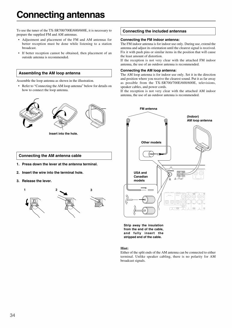
34
Connecting the included antennas
Connecting the FM indoor antenna:The FM indoor antenna is for indoor use only. During use, extend theantenna and adjust its orientation until the clearest signal is received.Fix it with push pins or similar items in the position that will causethe least amount of distortion.If the reception is not very clear with the attached FM indoorantenna, the use of an outdoor antenna is recommended.
Connecting the AM loop antenna:The AM loop antenna is for indoor use only. Set it in the directionand position where you receive the clearest sound. Put it as far awayas possible from the TX-SR700/700E/600/600E, televisions,speaker cables, and power cords.If the reception is not very clear with the attached AM indoorantenna, the use of an outdoor antenna is recommended.
Hint:Either of the split ends of the AM antenna can be connected to eitherterminal. Unlike speaker cabling, there is no polarity for AMbroadcast signals.
ANTENNA
FM75
AM
COAXIAL
OPTICAL12
IN IN INOUTOUT
DIGITAL INPUT VIDEO 2VIDEO 3
OPTICAL
COAXIALDIGITALINPUT
INOUTINDIGITALOUTPUT
IN
LRPHONO IN
OU
OU
Strip away the insulationfrom the end of the cable,and ful ly insert thestripped end of the cable.
(Indoor)AM loop antenna
Connecting antennas
Insert into the hole.
FM antenna
To use the tuner of the TX-SR700/700E/600/600E, it is necessary toprepare the supplied FM and AM antennas.
• Adjustment and placement of the FM and AM antennas forbetter reception must be done while listening to a stationbroadcast.
• If better reception cannot be obtained, then placement of anoutside antenna is recommended.
Assembling the AM loop antenna
Assemble the loop antenna as shown in the illustration.
• Refer to “Connecting the AM loop antenna” below for details onhow to connect the loop antenna.
Connecting the AM antenna cable
1. Press down the lever at the antenna terminal.
2. Insert the wire into the terminal hole.
3. Release the lever.
1 2 3
Other models
USA andCanadianmodels

35
Connecting antennas
Outdoor antenna
(Indoor)AM loop antenna
To TV (or VCR)To receiver
Connecting an FM outdoor antenna
Make sure to follow the general rules given below:
• Keep the antenna away from noise sources (neon signs, busyroads, etc.).
• It is dangerous to put the antenna close to power lines. Keep itwell away from power lines, transformers, etc.
• To avoid the risk of lightning and electrical shock, grounding isnecessary. Follow item 14 of the “Important Safeguards” onpage 2 when you install the outdoor antenna.
Connecting an AM outdoor antenna
If reception is poor with the indoor AM antenna, stretch out theoutdoor antenna (16 feet (5 meters) or more) above a window oroutside.
• Keep the indoor AM loop antenna connected. Do not remove it.
• To avoid the risk of lightning and electrical shock, grounding isnecessary. Follow item 14 of the “Important Safeguards” onpage 2 when you install the outdoor antenna.
Note:If you are using the TX-SR700/700E/600/600E worldwide model ina region where AM frequencies are delineated by 10-kHz steps, besure to set the “AM Frequency Step” Setup setting accordingly (seepage 56).
ANTENNA
FM75
AM
RPH
Directional linkage
Do not use the same antenna for both FM and TV (or VCR)reception since the FM and TV (or VCR) signals can interfere witheach other. If you must use a common FM/TV (or VCR) antenna, usea directional linkage type splitter.
Connecting the antenna cable to the 75/300 Ωantenna adapter (For all models other than USA &Canadian models and European models)
Connecting the 300 Ω ribbon wire:Loosen the screws on the adapter and wrap the wires of the ribbonwire around these screws. Then tighten the screws down with ascrewdriver.
Connecting the coaxial cable:
1. With your fingernail, or a small screwdriver, press thestoppers of the 75/300 Ω antenna adapter outwardand remove the cover.
2. Remove the transformer wire A from slit B and insertit into slit C.
3. Prepare the coaxial cable as shown in the diagram.
4. Connect the 75/300 Ω antenna adapter to the coaxialcable.1. Insert the end of the cable.2. Clamp it in place with pliers.
5. Reinstall the cover.
Outdoorantenna
300 Ωribbon wire
Slit B
Wire A
Slit C
1 2 3, 4
6mm
3mm
6mm
5/8"(15mm)
ANTENNA
FM75
AM
COAXIAL
OPTICAL12
DIGITAL INPUT VIDEO 2VIDEO 3
OPTICAL
INOUTINDIGITALOUTPUT
LRPHONO IN
O
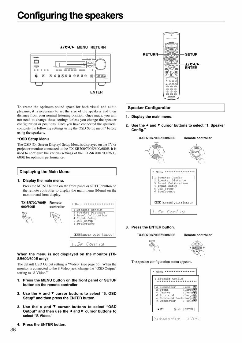
36
Configuring the speakers
To create the optimum sound space for both visual and audiopleasure, it is necessary to set the size of the speakers and theirdistance from your normal listening position. Once made, you willnot need to change these settings unless you change the speakerconfiguration or positions. Once you have connected the speakers,complete the following settings using the OSD Setup menu* beforeusing the speakers.
*OSD Setup MenuThe OSD (On Screen Display) Setup Menu is displayed on the TV orprojector monitor connected to the TX-SR700/700E/600/600E. It isused to configure the various settings of the TX-SR700/700E/600/600E for optimum performance.
Displaying the Main Menu
1. Display the main menu.Press the MENU button on the front panel or SETUP button onthe remote controller to display the main menu (Menu) on themonitor and front display.
When the menu is not displayed on the monitor (TX-SR600/600E only)The default OSD Output setting is “Video” (see page 56). When themonitor is connected to the S Video jack, change the “OSD Output”setting to “S Video.”
1. Press the MENU button on the front panel or SETUPbutton on the remote controller.
2. Use the and cursor buttons to select “5. OSDSetup” and then press the ENTER button.
3. Use the and cursor buttons to select “OSDOutput” and then use the and cursor buttons toselect “S Video.”
4. Press the ENTER button.
Speaker Configuration
1. Display the main menu.
2. Use the and cursor buttons to select “1. SpeakerConfig.”
3. Press the ENTER button.
The speaker configuration menu appears.
* Menu ***************** 1.Speaker Config 2.Speaker Distance 3.Level Calibration 4.Input Setup 5.OSD Setup 6.Preference
|ENTER|Quit:|SETUP|
Remotecontroller
TX-SR700/700E/600/600E
MENU RETURN
ENTER
///
RETURN SETUP
ENTER///
* Menu ***************** 1.Speaker Config 2.Speaker Distance 3.Level Calibration 4.Input Setup 5.OSD Setup 6.Preference
|ENTER|Quit:|SETUP|
* Menu ***************** 1.Speaker Config 2.Speaker Distance 3.Level Calibration 4.Input Setup 5.OSD Setup 6.Preference
1.Speaker Config *********************** a.Subwoofer :Yes b.Front :Large c.Center :Large d.Surround :Large e.Surround Back:Large f.Crossover : 80Hz
Quit:|SETUP|
Remote controllerTX-SR700/700E/600/600E
Remote controllerTX-SR700/700E/600/600E

37
Configuring the speakers
4. Use the and cursor buttons to select “Subwoofer”and then use the and cursor buttons to select thesubwoofer setting.
Yes: Select when a subwoofer is connected.
No: Select when a subwoofer is not connected.
5. Use the and cursor buttons to select “Front” andthen use the and cursor buttons to select the frontspeaker setting.
Large: Select if the front speakers are large sized.
Small: Select if the front speakers are small sized.
• If “No” is selected for the Subwoofer setting, this setting isfixed to “Large.”
6. Use the and cursor buttons to select “Center” andthen use the and cursor buttons to select thecenter speaker setting.
None: Select if no center speaker is connected.
Large: Select if the center speaker is large sized.
Small: Select if the center speaker is small sized.
• If “Small” is selected for the Front setting, “Large” cannot beselected for this setting.
7. Use the and cursor buttons to select “Surround”and then use the and cursor buttons to select thesurround speaker setting.
None: Select if no surround left and right speakers areconnected.
Large: Select if the surround left and right speakers are large sized.
Small: Select if the surround left and right speakers are small sized.
• If “Small” is selected for the Front setting, “Large” cannot beselected for this setting.
8. Use the and cursor buttons to select “Surroundback” and then use the and cursor buttons toselect the surround back speaker setting.
None: Select if no surround back speaker is connected.
Large: Select if the surround back speaker is large sized.
Small: Select if the surround back speaker is small sized.
• If “None” is selected for the Surround setting, this setting willnot appear.
• If “Small” is selected for the Surround setting, “Large” cannotbe selected for this setting.
9. Use the and cursor buttons to select “Crossover”and then use the and cursor buttons to select thecrossover frequency mode setting.
Adjustable Crossover (80/100/120 Hz) for Bass Management
This setting allows you to set the crossover frequency for yourspeaker system. This setting is valid when “Subwoofer” is set to“Yes,” or for speakers that are set to “Small,” at the “SpeakerConfig” menu. The crossover frequency is the minimumfrequency delivered to a speaker and can be set to 80 Hz, 100 Hz,or 120 Hz. Frequencies below this are cut from speakers set to“Small” and sent to the subwoofer (or to speakers set to“Large”).
Press the RETURN button to return to the main menu.Press the MENU button on the front panel or SETUP button on theremote controller to exit the Setup menu.
Remote controllerTX-SR700/700E/600/600E
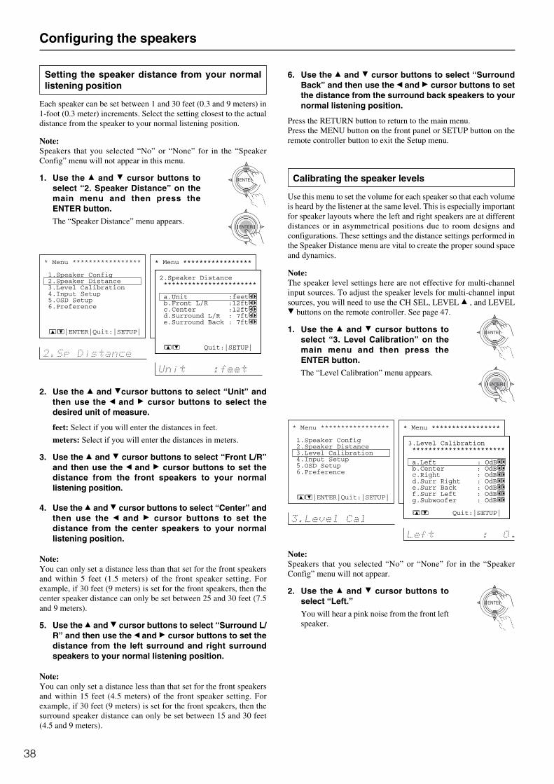
38
Configuring the speakers
Setting the speaker distance from your normallistening position
Each speaker can be set between 1 and 30 feet (0.3 and 9 meters) in1-foot (0.3 meter) increments. Select the setting closest to the actualdistance from the speaker to your normal listening position.
Note:Speakers that you selected “No” or “None” for in the “SpeakerConfig” menu will not appear in this menu.
1. Use the and cursor buttons toselect “2. Speaker Distance” on themain menu and then press theENTER button.The “Speaker Distance” menu appears.
2. Use the and cursor buttons to select “Unit” andthen use the and cursor buttons to select thedesired unit of measure.
feet: Select if you will enter the distances in feet.
meters: Select if you will enter the distances in meters.
3. Use the and cursor buttons to select “Front L/R”and then use the and cursor buttons to set thedistance from the front speakers to your normallistening position.
4. Use the and cursor buttons to select “Center” andthen use the and cursor buttons to set thedistance from the center speakers to your normallistening position.
Note:You can only set a distance less than that set for the front speakersand within 5 feet (1.5 meters) of the front speaker setting. Forexample, if 30 feet (9 meters) is set for the front speakers, then thecenter speaker distance can only be set between 25 and 30 feet (7.5and 9 meters).
5. Use the and cursor buttons to select “Surround L/R” and then use the and cursor buttons to set thedistance from the left surround and right surroundspeakers to your normal listening position.
Note:You can only set a distance less than that set for the front speakersand within 15 feet (4.5 meters) of the front speaker setting. Forexample, if 30 feet (9 meters) is set for the front speakers, then thesurround speaker distance can only be set between 15 and 30 feet(4.5 and 9 meters).
6. Use the and cursor buttons to select “SurroundBack” and then use the and cursor buttons to setthe distance from the surround back speakers to yournormal listening position.
Press the RETURN button to return to the main menu.Press the MENU button on the front panel or SETUP button on theremote controller button to exit the Setup menu.
Calibrating the speaker levels
Use this menu to set the volume for each speaker so that each volumeis heard by the listener at the same level. This is especially importantfor speaker layouts where the left and right speakers are at differentdistances or in asymmetrical positions due to room designs andconfigurations. These settings and the distance settings performed inthe Speaker Distance menu are vital to create the proper sound spaceand dynamics.
Note:The speaker level settings here are not effective for multi-channelinput sources. To adjust the speaker levels for multi-channel inputsources, you will need to use the CH SEL, LEVEL , and LEVEL
buttons on the remote controller. See page 47.
1. Use the and cursor buttons toselect “3. Level Calibration” on themain menu and then press theENTER button.The “Level Calibration” menu appears.
Note:Speakers that you selected “No” or “None” for in the “SpeakerConfig” menu will not appear.
2. Use the and cursor buttons toselect “Left.”You will hear a pink noise from the front leftspeaker.
* Menu ***************** 1.Speaker Config 2.Speaker Distance 3.Level Calibration 4.Input Setup 5.OSD Setup 6.Preference
|ENTER|Quit:|SETUP|
* Menu ***************** 1.Speaker Config 2.Speaker Distance 3.Level Calibration 4.Input Setup 5.OSD Setup 6.Preference
|ENTER|Quit:|SETUP|
* Menu ***************** 1.Speaker Config 2.Speaker Distance 3.Level Calibration 4.Input Setup 5.OSD Setup 6.Preference
2.Speaker Distance *********************** a.Unit :feet b.Front L/R :12ft c.Center :12ft d.Surround L/R : 7ft e.Surround Back : 7ft
Quit:|SETUP|
* Menu ***************** 1.Speaker Config 2.Speaker Distance 3.Level Calibration 4.Input Setup 5.OSD Setup 6.Preference
3.Level Calibration *********************** a.Left : OdB b.Center : OdB c.Right : OdB d.Surr Right : OdB e.Surr Back : OdB f.Surr Left : OdB g.Subwoofer : OdB
Quit:|SETUP|
db

39
Configuring the speakers
(1) Remember the volume level of this noise and then press the cursor button. The TX-SR700/700E/600/600E will now emit thepink noise from the center speaker.
(2) Using the and cursor buttons, adjust the volume level of thenoise from the center speaker so that it is at the same level as thatthat was emitted from the front left speaker.
(3) Press the cursor button again. The TX-SR700/700E/600/600Ewill now emit the pink noise from the front right speaker.
Use the and cursor buttons to adjust the volume of the noisefrom the front left speaker so that it is the same level as that thatwas emitted from the center speaker.
(4) Use the cursor button to select other speakers and adjust thevolumes until all speakers are adjusted to the same level.
The pink noise level can be adjusted to anywhere between –12 and+12 decibels for all speakers in 1-decibel increments.
Press the RETURN button to return to the main menu.Press the MENU button on the front panel or SETUP button on theremote controller button to exit the Setup menu.
Using the remote controller
1. Press the TEST button.You will hear a pink noise will be emittedfrom the front left speaker.
(1) Remember the volume level of this noise and then press the CHSEL button. The TX-SR700/700E/600/600E will now emit thepink noise from the center speaker.
(2) Using the LEVEL / buttons, adjust the volume level of thenoise from the center speaker so that it is at the same level as thatthat was emitted from the front left speaker.
(3) Press the CH SEL button again. The TX-SR700/700E/600/600Ewill now emit the pink noise from the front right speaker.
Use the LEVEL / buttons to adjust the volume of the noisefrom the front left speaker so that it is the same level as that thatwas emitted from the center speaker.
(4) Use the CH SEL button to select other speakers and adjust thevolumes until all speakers are adjusted to the same level.
The pink noise level can be adjusted to anywhere between –12 and+12 decibels for all speakers in 1-decibel increments.
2. Press the TEST button to completethe procedure.
Buttons on remote controller Buttons on TX-SR700/700E/600/600E
SETUP
(upper edge ofENTER button)
(lower edge ofENTER button)
(left edge ofENTER button)
(right edge ofENTER button)
ENTER
RETURN
MENU
UP
DOWN
LEFT
RIGHT
ENTER
RETURN
Displaying the Main Menu and exiting the menu
Selecting a menu or menu item
Setting the value
Selecting the menu
Returning to the previous screen
Buttons used for navigating through the menus
You can change settings in the Setup Menu using the buttons on thefront panel and on the remote controller.
The buttons on the remote controller correspond to those on the TX-SR700/700E/600/600E as shown below.
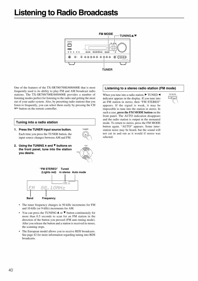
40
Listening to Radio Broadcasts
One of the features of the TX-SR700/700E/600/600E that is mostfrequently used is its ability to play FM and AM broadcast radiostations. The TX-SR700/700E/600/600E provides a number oflistening modes perfect for listening to the radio and getting the mostout of your audio system. Also, by presetting radio stations that youlisten to frequently, you can select them easily by pressing the CH
button on the remote controller.
Tuning into a radio station
1. Press the TUNER input source button.Each time you press the TUNER button, theinput source changes between AM and FM.
2. Using the TUNING and buttons onthe front panel, tune into the stationyou desire.
• The tuner frequency changes in 50-kHz increments for FMand 10-kHz (or 9-kHz) increments for AM.
• You can press the TUNING or button continuously formore than 0.5 seconds to scan for an FM station in thedirection of the button you pressed (FM auto tuning mode).After you release the button and a station is received in stereo,the scanning stops.
• The European model allows you to receive RDS broadcasts.See page 42 for more information regarding tuning into RDSbroadcasts.
Listening to a stereo radio station (FM mode)
When you tune into a radio station, TUNED indicator appears in the display. If you tune intoan FM station in stereo, then “FM STEREO”appears. If the signal is weak, it may beimpossible to tune into the station in stereo. Insuch a case, press the FM MODE button on thefront panel. The AUTO indication disappearsand the radio station is output in the monauralmode. To return to stereo, press the FM MODEbutton again. “AUTO” appears. Some inter-station noise may be heard, but the sound willnot cut in and out as it would if stereo wasselected.
FM MODE
TUNER
TUNING /
Tunedin stereo
Band Frequency
Auto mode“FM STEREO”
(Lights red)
AUTO
TUNED
FM STEREO

41
Listening to Radio Broadcasts
Presetting a radio station
1. Tune into the radio station you desire (see “Tuninginto a radio station”).
2. Press the MEMORY button on thefront panel.The MEMORY indicator lights red.
3. Using the PRESET / buttons,select a preset number (from 1 to 40)to assign the station.
4. Press the ENTER button to finalizethe procedure.The memory indicator turns off and theassigned number lights.
This programs the radio station as a preset radio station.
• Up to 40 stations can be stored in memory as preset radiostations.
“MEMORY”(Lights red) Flashes
Selecting a preset radio station
1. Press the TUNER input sourcebutton.
2. Press the PRESET / buttons andselect the number of the desiredpreset station.
When using the remote controller:
1. Press the RCVR MODE button.The RCVR MODE button lights green.
2. Press the TUN button.
3. Press the CH button and selectthe number of the desired presetstation.
Erasing a preset radio station
This can only be performed at the TX-SR700/700E/600/600E.
1. Press the TUNER button and pressthe PRESET / buttons to select thepreset radio station that you want toerase (see above).
2. Press and hold the MEMORY buttonand then press the FM MODE button.
The selected preset station is erased.
AUTO
TUNED
ch
MEMORY
MEMORYFM MODE
ENTERTUNER
CH
TUN
RCVRPRESET /
ch
Lights
AUTO
TUNED
ch
42
Listening to RDS broadcasts (European models only)
Listening to RDS broadcasts
RDS reception is available only on the European model and only inareas where RDS broadcasts are available.
What is RDS?RDS stands for Radio Data System and is a type of FM broadcasting.RDS was developed within the European Broadcasting Union(EBU) and is available in most European countries. Many FMbroadcasting stations now transmit the RDS signals, which providethe additional information required. RDS provides you with variousservices so that you can choose a station that broadcasts yourfavorite categories of music, news, or other information.
There are three main classifications of RDS broadcasts. Though theycan be tuned into by using the TUNING buttons as normal stations,RDS broadcasts allow you to scan for stations of the type andclassification for which you are looking. This makes it much easierfor you to find the station you want (see “Performing a PTY scan”and “Performing a TP scan” on page 43). The three mainclassifications are explained below.
RT: Radio TextWhen an RDS station broadcasting RT information is selected, thetext information received from the station is displayed.
PTY: Program TypeWhen an RDS station broadcasting PTY information is selected, thestation type (classification) is displayed.
TP: Traffic ProgramWhen an RDS station broadcasting TP information is selected,traffic information will be broadcasted periodically.
Notes:• In some cases, the characters displayed on the display of the TX-
SR700E/600E may not be exactly the same as the ones broadcastby the radio station. Also, unusual characters may appear on thedisplay if the TX-SR700E/600E receives characters that cannotbe displayed correctly. This is not a malfunction.
• When an RDS station broadcasting PS information is selected,the name of the station is displayed instead of the frequency.
PTY program types in Europe
The text given below in parenthesis is what is actually displayed onthe TX-SR700E/600E.
None (NONE):No program type.
News reports (NEWS):Reports on current events and happenings.
Current affairs (AFFAIRS):Topical reporting of current affairs, often with a wider range oftopics than news reports.
Information (INFO):General information such as weather forecasts, consumer affairs,medical help, etc.
Sport (SPORT):Live sports action, sports news, and interviews.
Education (EDUCATE):Formal educational programs.
Drama (DRAMA):Radio plays and serials.
Culture (CULTURE):Cultural programs (including religious affairs).
Science and technology (SCIENCE):Programs about the natural sciences and technology.
Varied (VARIED):Speech-based programs not covered by the above categories (e.g.,quizzes, panel games, and comedy).
Pop music (POP M):Popular commercial music, usually from past or present sales charts(e.g., Top 40).
Rock music (ROCK M):Popular music with an alternative appeal, often not appearing onsales charts.
Middle of the road music (M.O.R.M):Easy listening music (as opposed to Pop, Rock, or Classical).
Light classics (LIGHT M):Classical music for general rather than specialist appreciation.
Serious classics (CLASSICS):Performances of major orchestral works, symphonies, chambermusic, etc. (including the Grand Opera).
Other music (OTHER M):Music styles not covered by the above categories (e.g., Jazz, Rhythm& Blues, Folk, Country, and Reggae).
• Alarm (ALARM):When an RDS station is making an emergency broadcast,ALARM will flash on the display.

43
Listening to RDS broadcasts
Displaying Radio Text (RT)
If the station you are currently tuned into is broadcasting RT signals,they will be displayed in the front display of the TX-SR700E/600E.If the station does not, this function will be ignored.
1. To display the radio text, press theRT/PTY/TP button once.
• If the station you are currently listening to is not an RDS station,only the frequency of the station will appear.
• If “Waiting” appears on the display, more time is required toreceive the RT information. When the information is received,the characters will scroll across the front display.
• If “No Text Data” appears on the display, RT information is notavailable.
• The display shows the frequency for 3 seconds and returns toprogram service name.
Performing a PTY scan
1. Press the TUNER input source buttonand select the FM input source.
2. Press the RT/PTY/TP button twice.
The current program type appears on thedisplay.
3. Using the / buttons, select the PTYprogram type you desire.
4. Press the ENTER button.
The TX-SR700E/600E will scan until itreaches a station of the program type youselected. It will then stop briefly at thatstation before continuing on until it reachesthe next station. Pressing the ENTER buttonstops the PTY scan at that point. If you pressthe RT/PTY/TP while “NONE” isdisplayed, “PTY ?” will appear. In this case,return to step 3.
5. Press the ENTER button when itreaches the station to which you wantto listen.
“Not Found” will appear when no RDSsignal is being received from the station.
Performing a TP scan
1. Press the TUNER input source buttonand select the FM input source.
2. Press the RT/PTY/TP button threetimes.
“[TP]” will appear if the current station is broadcasting TPsignals. This station will periodically broadcast trafficinformation. To find a different station, proceed to the next step.Also, if “TP” is displayed, proceed to the next step.
3. Press the ENTER button.The TX-SR700E/600E will scan until itreaches a station broadcasting trafficinformation. If “Not Found” appears on thedisplay, a TP station cannot be located.
RT/PTY/TP
TUNER
PRESET /
ENTER

44
Selecting an Audio Component
Basic operation (TX-SR700/700E)
If you want to perform these operations using the remote controller,first press the RCVR MODE button.
1. Press the desired input source.
The selected source name appears on the display. See “Enjoyingthe multichannel output” (see page 47) when a DVD player witha 5.1-channel input port is connected to the TX-SR700/700E.
2. Start playing the selected input source.
Follow the operating instructions for the source device.
3. Adjust the volume to an appropriate level.
Adjusting the main volume adjusts the volume level of all thespeakers connected to the TX-SR700/700E together. Ifheadphones are connected, this also adjusts the volume heardfrom the headphone speakers. To adjust the volume, either pressthe VOL buttons on the remote controller or turn theMASTER VOLUME dial. To increase the volume, turn the dialclockwise; to decrease the volume, turn the dialcounterclockwise. The volume can be set to Min, 1 to 99, andMax.
TX-SR700/700E
Remote controller
TX-SR700/700E Remote controller
TX-SR700/700E
MASTER VOLUME
VOL
RCVRMODE
Input source buttons
INPUT SELECTORbuttons
• For more information about selecting the listening mode, seepage 49.
• You can set the sound quality using the Audio Adjust menu.(See page 57 for more information.)If no audio output is heard from the digital source (DVD, CD,etc.) you have selected, see “Digital Input” on page 53.

45
Selecting an Audio Component
TX-SR600/600E
TX-SR600/600E
Remote controller
TX-SR600/600E Remote controller
MASTER VOLUME
SPEAKERS A/B
VOL
SP A/B
RCVRMODE
Input source buttons
INPUT SELECTORbuttons
• For more information about selecting the listening mode, seepage 49.
• You can set the sound quality using the Audio Adjust menu.(See page 57 for more information.)If no audio output is heard from the digital source (DVD, CD,etc.) you have selected, see “Digital Input” on page 53.
Selecting speakers (SPEAKERS A, B) (TX-SR600/600E only)
SPEAKERS A: This button turns on or off the speakers connected tothe FRONT SPEAKERS, CENTER SPEAKER, SURROUNDSPEAKERS, SURROUND BACK SPEAKER, and SUBWOOFERterminals.When you listen to surround audio or select multi channel input, besure to turn on SPEAKERS A.When the speakers are turned on, the SPEAKERS A indicator ( )lights up.
SPEAKERS B: This button turns on or off the speakers connectedto the FRONT SPEAKERS B terminals.When the speakers are turned on, the SPEAKERS B indicator ( )
lights up.
Notes:• You cannot select surround sound when you are using
SPEAKERS B.
• When using the B speakers, the A speakers can only be used forstereo or direct playback. Audio is output from the subwoofer.However, when playing a multichannel audio source, sound isnot output to the center speaker, surround speakers, surroundback speaker, and subwoofer.
Basic operation (TX-SR600/600E)
To use the remote controller, first press the RCVR MODE button.
1. Press the desired input source button.
The selected source name appears on the display. See “Enjoyingthe multichannel output” (see page 47) when a DVD player witha 5.1-channel input port is connected to the TX-SR600/600E.
2. Make sure that the SPEAKERS A
indicator ( ) is lit on the display.If it is not lit, press the SPEAKERSA (SP A) button.(Refer to the “Selecting speakers” section on this page for moredetails.)
3. Start playing the selected input source.Follow the operating instructions for the source device.
4. Adjust the volume to an appropriate level.These controls allow you to adjust the volume of the front Aspeakers, center speaker, surround speakers, surround backspeaker, and subwoofer simultaneously. Turning the controlclockwise increases the volume level. Turning the controlcounterclockwise decreases the volume. The volume can be setto Min, 1 to 99, and Max.
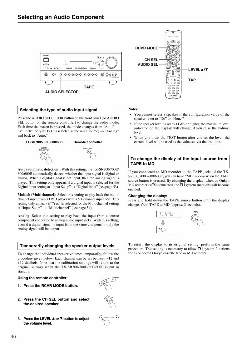
46
Notes:• You cannot select a speaker if the configuration value of the
speaker is set to “No” or “None.”
• If the speaker level is set to +1 dB or higher, the maximum levelindicated on the display will change if you raise the volumelevel.
• When you press the TEST button after you set the level, thecurrent level will be used as the value set via the test tone.
To change the display of the input source fromTAPE to MD
If you connected an MD recorder to the TAPE jacks of the TX-SR700/700E/600/600E, you can have “MD” appear when the TAPEsource button is pressed. By changing the display, when an OnkyoMD recorder is -connected, the system functions will becomeenabled.
Changing the display:Press and hold down the TAPE source button until the displaychanges from TAPE to MD (approx. 3 seconds).
To return the display to its original setting, perform the sameprocedure. This setting is necessary to allow z system functionsfor a connected Onkyo cassette tape or MD recorder.
Selecting the type of audio input signal
Press the AUDIO SELECTOR button on the front panel (or AUDIOSEL button on the remote controller) to change the audio mode.Each time the button is pressed, the mode changes from “Auto” →“Multich” (only if DVD is selected as the input source) → “Analog”and back to “Auto.”
Auto (automatic detection): With this setting, the TX-SR700/700E/600/600E automatically detects whether the input signal is digital oranalog. When a digital signal is not input, then the analog signal isplayed. This setting only appears if a digital input is selected for theDigital Input setting at “Input Setup” → “Digital Input” (see page 53).
Multich (Multichannel): Select this setting to play back the multi-channel input from a DVD player with a 5.1-channel input port. Thissetting only appears if “Yes” is selected for the Multichannel settingat “Input Setup” → “Multichannel” (see page 54).
Analog: Select this setting to play back the input from a sourcecomponent connected to analog audio input jacks. With this setting,even if a digital signal is input from the same component, only theanalog signal will be output.
Temporarily changing the speaker output levels
To change the individual speaker volumes temporarily, follow theprocedure given below. Each channel can be set between –12 and+12 decibels. Note that the calibration settings will return to theoriginal settings when the TX-SR700/700E/600/600E is put instandby.
Using the remote controller:
1. Press the RCVR MODE button.
2. Press the CH SEL button and selectthe desired speaker.
3. Press the LEVEL or button to adjustthe volume level.
Selecting an Audio Component
TAPEAUDIO SELECTOR
TAP
LEVELAUDIO SEL
RCVR MODE
CH SEL
/
TX-SR700/700E/600/600E Remote controller

47
Selecting an Audio Component
Using the sleep time (remote controller only)
The SLEEP button enables you to set the TX-SR700/700E/600/600E to turn off automatically after a specified time period. If youpress it once, the TX-SR700/700E/600/600E will turn off after 90minutes. Each time it is pressed thereafter, this remaining time untilthe TX-SR700/700E/600/600E turns off decreases by 10 minutes(i.e., from 90 to 80 minutes). While, the sleep function is enabled,you can press the SLEEP button to see how much time is left. If theSLEEP button is pressed when the time displayed is less than 10minutes, the sleep function is cancelled.
(TX-SR700/700E only)
If you are using the remote zone (Zone 2), it will turn off at the sametime as the main zone. If you want to set the sleep function for Zone2 only, set the sleep function with the main zone turned on and thenput the main zone into the standby state.
Listening with headphones
To listen with headphones, plug a pair of headphones with a standardstereo plug into the PHONES jack on the TX-SR700/700E/600/600E front panel.
When you connect the headphones, the TX-SR700/700E/600/600Ewill enter the STEREO mode automatically and no sound will beheard from the speakers. When the headphones are unplugged, theTX-SR700/700E/600/600E returns to its original listening mode.When using the headphones, you can only use the Direct, Stereo, andPure Audio (TX-SR700/700E only) listening modes. If you haveselected multichannel audio, you will only hear the sound output tothe front right and left channels.
The headphone volume level can be adjusted at the Setup Menu (seepage 56).
(TX-SR700/700E only)
Note:The signal to the remote zone (Zone 2) will not be affected bywhether or not headphones are connected.
Enjoying DVD multichannel audio playback
Before starting operations, first make sure that the multichannelconnection is properly made and that “Yes” is selected for theMultichannel setting at “Input Setup” → “Multichannel” (see page 54).
1. Press the DVD input source button.
2. Select “Multich” using the AUDIO SELECTOR buttonon the front panel (or AUDIO SEL button on the remotecontroller).
3. Turn on the connected DVD player and start playingthe desired media.
4. If necessary, adjust the output level of each speakeras desired (see page 46).Adjust the volume at each speaker so that all the volumes soundat the same level at the listening position. For the front right,front left, center, surround right, and surround left speakers, theoutput levels can be adjusted between –12 and +12 decibels. Thesubwoofer can be adjusted between –30 and +12 decibels.
5. Adjust the volume with the MASTER VOLUME dial orthe VOL buttons on the remote controller.
AUDIO ADJUST
AUDIO SELECTORPHONES
AUDIO ADJUST
MUTINGAUDIO SEL
MASTER VOLUME
///
///
VOL
SLEEP
Remote controllerTX-SR700/700E/600/600E Remote controller
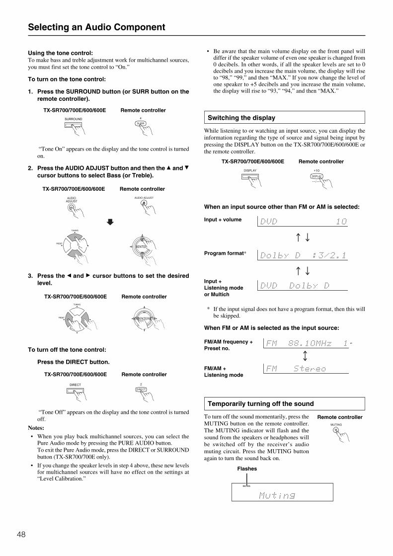
48
Using the tone control:To make bass and treble adjustment work for multichannel sources,you must first set the tone control to “On.”
To turn on the tone control:
1. Press the SURROUND button (or SURR button on theremote controller).
“Tone On” appears on the display and the tone control is turnedon.
2. Press the AUDIO ADJUST button and then the and cursor buttons to select Bass (or Treble).
3. Press the and cursor buttons to set the desiredlevel.
To turn off the tone control:
Press the DIRECT button.
“Tone Off” appears on the display and the tone control is turnedoff.
Notes:• When you play back multichannel sources, you can select the
Pure Audio mode by pressing the PURE AUDIO button.To exit the Pure Audio mode, press the DIRECT or SURROUNDbutton (TX-SR700/700E only).
• If you change the speaker levels in step 4 above, these new levelsfor multichannel sources will have no effect on the settings at“Level Calibration.”
Selecting an Audio Component
TX-SR700/700E/600/600E Remote controller
TX-SR700/700E/600/600E Remote controller
• Be aware that the main volume display on the front panel willdiffer if the speaker volume of even one speaker is changed from0 decibels. In other words, if all the speaker levels are set to 0decibels and you increase the main volume, the display will riseto “98,” “99,” and then “MAX.” If you now change the level ofone speaker to +5 decibels and you increase the main volume,the display will rise to “93,” “94,” and then “MAX.”
Switching the display
While listening to or watching an input source, you can display theinformation regarding the type of source and signal being input bypressing the DISPLAY button on the TX-SR700/700E/600/600E orthe remote controller.
When an input source other than FM or AM is selected:
* If the input signal does not have a program format, then this willbe skipped.
When FM or AM is selected as the input source:
Temporarily turning off the sound
To turn off the sound momentarily, press theMUTING button on the remote controller.The MUTING indicator will flash and thesound from the speakers or headphones willbe switched off by the receiver’s audiomuting circuit. Press the MUTING buttonagain to turn the sound back on.
Input + volume
Program format*
Input +Listening modeor Multich
FM/AM frequency +Preset no.
FM/AM +Listening mode
ch
Remote controller
Flashes
Remote controllerTX-SR700/700E/600/600E
TX-SR700/700E/600/600E Remote controller
Remote controllerTX-SR700/700E/600/600E

49
Listening ModesThe TX-SR700/700E/600/600E’s surround sound enables you toenjoy the presence of a movie theater or concert hall in your room.
The configuration of the speakers is very important for the surroundsound. Refer to “Connecting speakers” on page 30.
Before using a listening mode, make sure the Speaker Config,Speaker Distance, and Level Calibration parameters have been set(see pages 36 to 39) . Once the parameters have been set, it is notnecessary to set them again. See page 51 for information regardinghow to select the listening mode.
Dolby D (Dolby Digital)The Dolby D mode is used to play Dolby Digital sources.Dolby Digital is digital data with AC-3 compression and a maximumof 5.1-channel* surround sound. This source signal comes fromDVDs and LDs that have the mark and therefore recorded for5.1-channel output. This source also comes from digital satellitebroadcasts that support Dolby Digital.
* 5.1-channel Digital FormatThe 5.1-channel digital surround format has a variety of versionsincluding Dolby Digital and DTS. The 5.1-channel digitalsurround format enables the individual recording and playing offive full-range (20 Hz to 20 kHz) channels (left and right front,center, and two surround channels) plus an LFE channel (LowFrequency Effect) for the low-range effect sound. It will create arealistic sound that can be heard in the theaters and concert halls.
Dolby Digital EXWhen using surround back speakers, the Dolby Digital source isplayed back using the Matrix 6.1-channel decoder.
DTSThe DTS mode is used to play DTS sources.DTS (Digital Theater System) is compressed digital data with amaximum 5.1-channel surround output (6.1-channel with DTS-ESDiscrete sources) that allows for an extremely high-quality sound.This source signal requires a DVD player that supports DTS outputand comes from DVDs, compact discs, and LDs that have the mark.
DTS-ES Discrete 6.1With the addition of the surround back channel, this new format hasall 6.1 channels recorded independently for a completely discretedigital format. Since all channels are recorded independently, high-fidelity surround playback with the increased feeling of a separatedsound space is achieved.
DTS-ES Matrix 6.1This format has the surround back channel matrix encoded andinserted into the left and right surround channels so that at playbackthe output for the left, right, and back surround channels are decodedusing a high-precision matrix decoder.
Dolby Pro Logic IIOpposed to Dolby Pro Logic, which had four channels (front, left,center, and surround) recorded into two channels with matrixprocessing and then played back in four channels, Dolby Pro LogicII uses a feedback logic circuit to have 5.1-channel surround audio(Dolby Surround, etc.) matrix-encoded into two channels and thenplayed back in its original 5.1-channel form.Dolby Pro Logic II provides a Movie mode designed for playingmovies and a Music mode designed for listening to music. In theMovie mode, the surround channels, which used to providemonaural output over only a narrow frequency range, now providecomplete stereo output over the full frequency range. The result ismovie viewing with a realistic feel of movement. The Music modeuses the surround channels to provide a natural soundfield thatcannot be provided with normal stereo output.
This mode can be used with VHS and DVD videos with the mark and certain television programs. The Music mode
can be used with music compact discs and other stereo sources.
DTS Neo:6This mode is for 6.1-channel playback of sources such as PCM oranalog sources that have only two channels. The outputs of all sixchannels are a wide frequency range with a great separation betweenthe different channels.
This mode can be set to the Cinema mode designed for playingmovies and the Music mode designed for listening to music.
The Cinema mode is good for movies. The reproduced surroundsound provide the same realistic feel of movement as 6.1-channelsources. This mode can be used with VHS and television programswith stereo sound.
The Music mode uses the surround channels to provide a naturalsound space that cannot be provided with normal stereo output. Thismode can be used with music CDs and other stereo sources.
DirectThis mode delivers pure sound with minimum sound qualityadjustment and filtration. The sound recorded for the right and leftfront channels is output to the right and left front speakers only andnot output to the subwoofer.
Pure Audio (TX-SR700/700E only)Same as the direct mode except that the pure audio mode also turnsoff the display window, turns off the power supply to the videocircuitry, and minimizes the sources of noise. The result is high-fidelity music playback true to the original source.
Note that if you connect a device to the COMPONENT VIDEOINPUT 2 jacks of the TX-SR700/700E, the relay switch activatesand signals are output to the COMPONENT VIDEO OUTPUTjacks. Therefore, the display on the monitor connected to theCOMPONENT VIDEO OUTPUT jacks will not disappear.
StereoThis mode has all the input sound output from the left and right frontspeakers. The subwoofer is also used for playback.

50
Listening Modes
OrchestraThis mode is appropriate for classical and opera music. The centerchannel is cut and the surround channels are emphasized to widenthe stereo image. It will simulate the natural reverberation that iscreated in large halls.
UnpluggedThis mode is suitable for acoustical instrumental sounds, vocals, andjazz music. By emphasizing the front stereo image, it will simulatethe acoustics that you would experience in front of the stage.
Studio-MixThis mode is for rock and popular music. The lively sounds areenhanced for a powerful acoustic image that simulates the feeling ofbeing in a club or rock concert.
TV LogicThis mode gives realistic acoustics to TV programs that are airedfrom TV studios. It enhances the entire surround sound and clarity ofthe conversation.
All Ch StereoThis mode is designed for playing background music. The front,surround, and surround back channels create a stereo image thatencompasses the entire area.
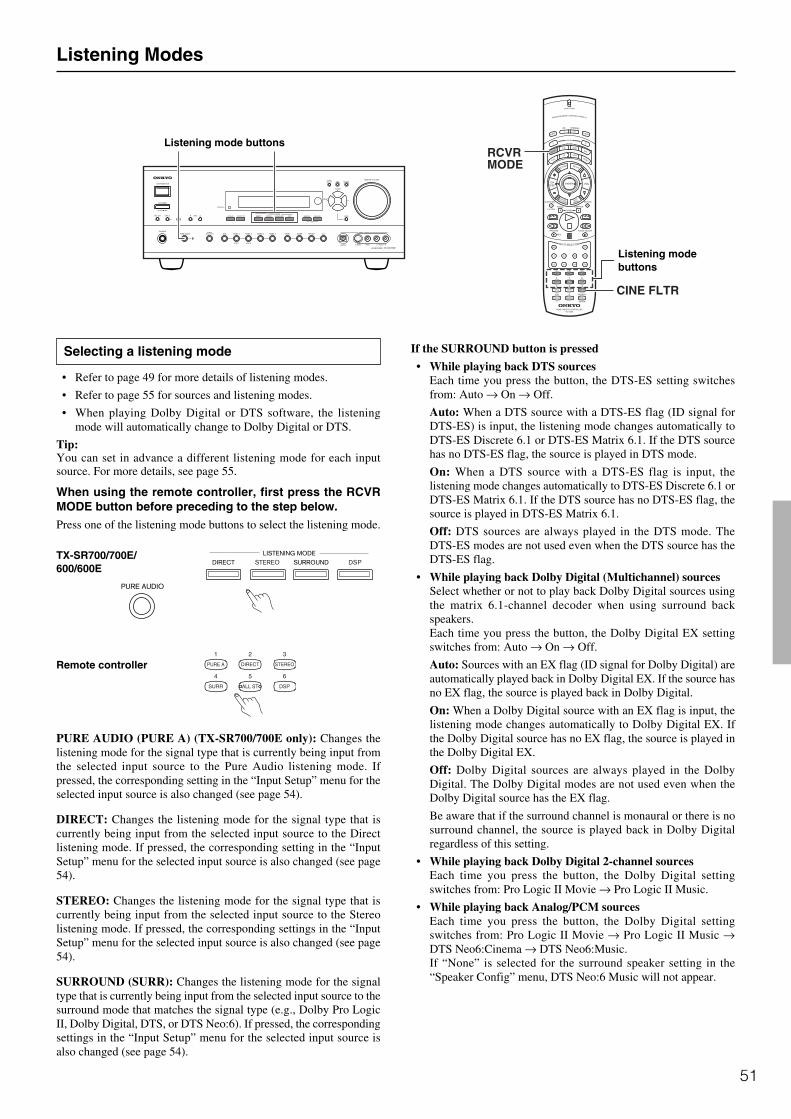
51
Listening Modes
Selecting a listening mode
• Refer to page 49 for more details of listening modes.
• Refer to page 55 for sources and listening modes.
• When playing Dolby Digital or DTS software, the listeningmode will automatically change to Dolby Digital or DTS.
Tip:You can set in advance a different listening mode for each inputsource. For more details, see page 55.
When using the remote controller, first press the RCVRMODE button before preceding to the step below.
Press one of the listening mode buttons to select the listening mode.
PURE AUDIO (PURE A) (TX-SR700/700E only): Changes thelistening mode for the signal type that is currently being input fromthe selected input source to the Pure Audio listening mode. Ifpressed, the corresponding setting in the “Input Setup” menu for theselected input source is also changed (see page 54).
DIRECT: Changes the listening mode for the signal type that iscurrently being input from the selected input source to the Directlistening mode. If pressed, the corresponding setting in the “InputSetup” menu for the selected input source is also changed (see page54).
STEREO: Changes the listening mode for the signal type that iscurrently being input from the selected input source to the Stereolistening mode. If pressed, the corresponding settings in the “InputSetup” menu for the selected input source is also changed (see page54).
SURROUND (SURR): Changes the listening mode for the signaltype that is currently being input from the selected input source to thesurround mode that matches the signal type (e.g., Dolby Pro LogicII, Dolby Digital, DTS, or DTS Neo:6). If pressed, the correspondingsettings in the “Input Setup” menu for the selected input source isalso changed (see page 54).
If the SURROUND button is pressed
• While playing back DTS sourcesEach time you press the button, the DTS-ES setting switchesfrom: Auto → On → Off.
Auto: When a DTS source with a DTS-ES flag (ID signal forDTS-ES) is input, the listening mode changes automatically toDTS-ES Discrete 6.1 or DTS-ES Matrix 6.1. If the DTS sourcehas no DTS-ES flag, the source is played in DTS mode.
On: When a DTS source with a DTS-ES flag is input, thelistening mode changes automatically to DTS-ES Discrete 6.1 orDTS-ES Matrix 6.1. If the DTS source has no DTS-ES flag, thesource is played in DTS-ES Matrix 6.1.
Off: DTS sources are always played in the DTS mode. TheDTS-ES modes are not used even when the DTS source has theDTS-ES flag.
• While playing back Dolby Digital (Multichannel) sourcesSelect whether or not to play back Dolby Digital sources usingthe matrix 6.1-channel decoder when using surround backspeakers.Each time you press the button, the Dolby Digital EX settingswitches from: Auto → On → Off.
Auto: Sources with an EX flag (ID signal for Dolby Digital) areautomatically played back in Dolby Digital EX. If the source hasno EX flag, the source is played back in Dolby Digital.
On: When a Dolby Digital source with an EX flag is input, thelistening mode changes automatically to Dolby Digital EX. Ifthe Dolby Digital source has no EX flag, the source is played inthe Dolby Digital EX.
Off: Dolby Digital sources are always played in the DolbyDigital. The Dolby Digital modes are not used even when theDolby Digital source has the EX flag.
Be aware that if the surround channel is monaural or there is nosurround channel, the source is played back in Dolby Digitalregardless of this setting.
• While playing back Dolby Digital 2-channel sourcesEach time you press the button, the Dolby Digital settingswitches from: Pro Logic II Movie → Pro Logic II Music.
• While playing back Analog/PCM sourcesEach time you press the button, the Dolby Digital settingswitches from: Pro Logic II Movie → Pro Logic II Music →DTS Neo6:Cinema → DTS Neo6:Music.If “None” is selected for the surround speaker setting in the“Speaker Config” menu, DTS Neo:6 Music will not appear.
CINE FLTR
RCVRMODE
Listening mode buttons
Listening modebuttons
Remote controller
TX-SR700/700E/600/600E
52
Listening Modes
ALL ST (remote controller only): Changes the listening mode forthe signal type that is currently being input from the selected inputsource to the All Ch Stereo listening mode. If pressed, thecorresponding setting in the “Input Setup” menu for the selectedinput source is also changed (see page 54).
DSP: Changes the listening mode for the signal type that is currentlybeing input from the selected input source as shown below.
Orchestra → Unplugged → Studio-Mix → TV Logic → All ChStereo → Orchestra.
If pressed, the corresponding settings in the “Input Setup” menu forthe selected input source is also changed (see page 54).
Original filter (CinemaFILTER) loading for movies
The CinemaFILTER function gently decreases the level of theextreme high frequencies, compensating for overly-bright soundingmotion picture soundtracks. Select this function if the sound fromthe front speakers is too bright.
This function only works in the Dolby Digital, Dolby Digital EX,Dolby Pro Logic II Movie, DTS, DTS-ES Discrete 6.1, DTS-ESMatrix 6.1, DTS Neo:6 Cinema Surround modes.
Press the CINE FLTR button on the remote controller.
The current setting is displayed. Press the button again to change thesetting.
On: The CinemaFILTER function is used during playback.
Off: The CinemaFILTER function is not used during playback.
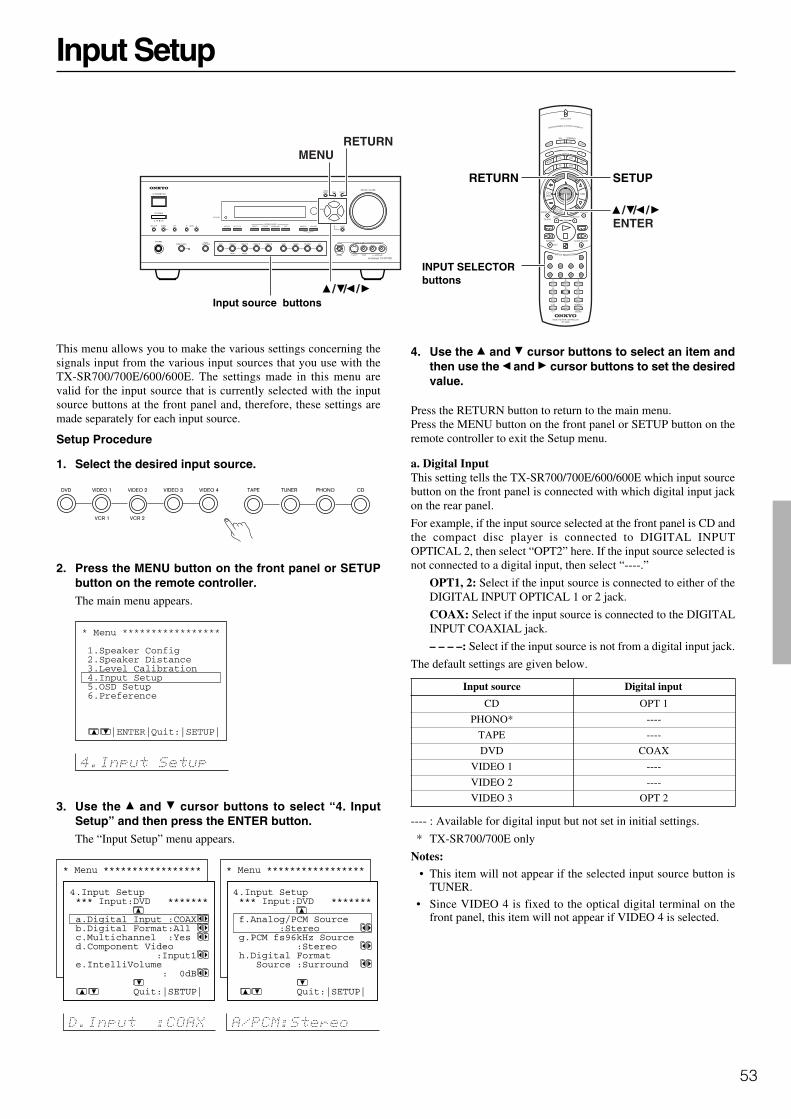
53
Input Setup
This menu allows you to make the various settings concerning thesignals input from the various input sources that you use with theTX-SR700/700E/600/600E. The settings made in this menu arevalid for the input source that is currently selected with the inputsource buttons at the front panel and, therefore, these settings aremade separately for each input source.
Setup Procedure
1. Select the desired input source.
2. Press the MENU button on the front panel or SETUPbutton on the remote controller.The main menu appears.
3. Use the and cursor buttons to select “4. InputSetup” and then press the ENTER button.The “Input Setup” menu appears.
4. Use the and cursor buttons to select an item andthen use the and cursor buttons to set the desiredvalue.
Press the RETURN button to return to the main menu.Press the MENU button on the front panel or SETUP button on theremote controller to exit the Setup menu.
a. Digital InputThis setting tells the TX-SR700/700E/600/600E which input sourcebutton on the front panel is connected with which digital input jackon the rear panel.
For example, if the input source selected at the front panel is CD andthe compact disc player is connected to DIGITAL INPUTOPTICAL 2, then select “OPT2” here. If the input source selected isnot connected to a digital input, then select “----.”
OPT1, 2: Select if the input source is connected to either of theDIGITAL INPUT OPTICAL 1 or 2 jack.
COAX: Select if the input source is connected to the DIGITALINPUT COAXIAL jack.
– – – –: Select if the input source is not from a digital input jack.
The default settings are given below.
Input source Digital input
CD OPT 1
PHONO* ----
TAPE ----
DVD COAX
VIDEO 1 ----
VIDEO 2 ----
VIDEO 3 OPT 2
---- : Available for digital input but not set in initial settings.
* TX-SR700/700E only
Notes: • This item will not appear if the selected input source button is
TUNER.
• Since VIDEO 4 is fixed to the optical digital terminal on thefront panel, this item will not appear if VIDEO 4 is selected.
MENURETURN
///
RETURN SETUP
///ENTER
Input source buttons
INPUT SELECTORbuttons
* Menu ***************** 1.Speaker Config 2.Speaker Distance 3.Level Calibration 4.Input Setup 5.OSD Setup 6.Preference
4.Input Setup *** Input:DVD ******* a.Digital Input :COAX b.Digital Format:All c.Multichannel :Yes d.Component Video :Input1 e.IntelliVolume : 0dB
Quit:|SETUP|
* Menu ***************** 1.Speaker Config 2.Speaker Distance 3.Level Calibration 4.Input Setup 5.OSD Setup 6.Preference
4.Input Setup *** Input:DVD ******* f.Analog/PCM Source :Stereo g.PCM fs96kHz Source :Stereo h.Digital Format Source :Surround
Quit:|SETUP|
* Menu ***************** 1.Speaker Config 2.Speaker Distance 3.Level Calibration 4.Input Setup 5.OSD Setup 6.Preference
|ENTER|Quit:|SETUP|
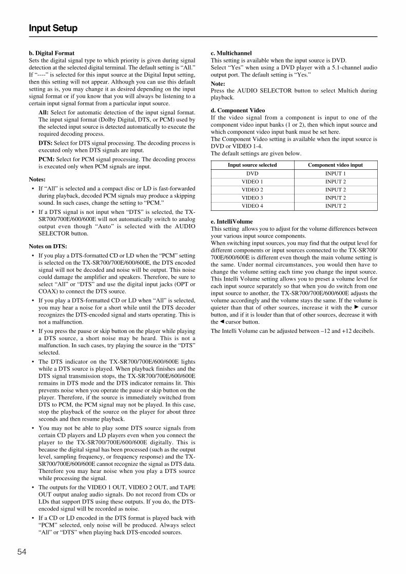
54
b. Digital FormatSets the digital signal type to which priority is given during signaldetection at the selected digital terminal. The default setting is “All.”If “----” is selected for this input source at the Digital Input setting,then this setting will not appear. Although you can use this defaultsetting as is, you may change it as desired depending on the inputsignal format or if you know that you will always be listening to acertain input signal format from a particular input source.
All: Select for automatic detection of the input signal format.The input signal format (Dolby Digital, DTS, or PCM) used bythe selected input source is detected automatically to execute therequired decoding process.
DTS: Select for DTS signal processing. The decoding process isexecuted only when DTS signals are input.
PCM: Select for PCM signal processing. The decoding processis executed only when PCM signals are input.
Notes:
• If “All” is selected and a compact disc or LD is fast-forwardedduring playback, decoded PCM signals may produce a skippingsound. In such cases, change the setting to “PCM.”
• If a DTS signal is not input when “DTS” is selected, the TX-SR700/700E/600/600E will not automatically switch to analogoutput even though “Auto” is selected with the AUDIOSELECTOR button.
Notes on DTS:
• If you play a DTS-formatted CD or LD when the “PCM” settingis selected on the TX-SR700/700E/600/600E, the DTS encodedsignal will not be decoded and noise will be output. This noisecould damage the amplifier and speakers. Therefore, be sure toselect “All” or “DTS” and use the digital input jacks (OPT orCOAX) to connect the DTS source.
• If you play a DTS-formatted CD or LD when “All” is selected,you may hear a noise for a short while until the DTS decoderrecognizes the DTS-encoded signal and starts operating. This isnot a malfunction.
• If you press the pause or skip button on the player while playinga DTS source, a short noise may be heard. This is not amalfunction. In such cases, try playing the source in the “DTS”selected.
• The DTS indicator on the TX-SR700/700E/600/600E lightswhile a DTS source is played. When playback finishes and theDTS signal transmission stops, the TX-SR700/700E/600/600Eremains in DTS mode and the DTS indicator remains lit. Thisprevents noise when you operate the pause or skip button on theplayer. Therefore, if the source is immediately switched fromDTS to PCM, the PCM signal may not be played. In this case,stop the playback of the source on the player for about threeseconds and then resume playback.
• You may not be able to play some DTS source signals fromcertain CD players and LD players even when you connect theplayer to the TX-SR700/700E/600/600E digitally. This isbecause the digital signal has been processed (such as the outputlevel, sampling frequency, or frequency response) and the TX-SR700/700E/600/600E cannot recognize the signal as DTS data.Therefore you may hear noise when you play a DTS sourcewhile processing the signal.
• The outputs for the VIDEO 1 OUT, VIDEO 2 OUT, and TAPEOUT output analog audio signals. Do not record from CDs orLDs that support DTS using these outputs. If you do, the DTS-encoded signal will be recorded as noise.
• If a CD or LD encoded in the DTS format is played back with“PCM” selected, only noise will be produced. Always select“All” or “DTS” when playing back DTS-encoded sources.
Input Setup
c. MultichannelThis setting is available when the input source is DVD.Select “Yes” when using a DVD player with a 5.1-channel audiooutput port. The default setting is “Yes.”
Note:Press the AUDIO SELECTOR button to select Multich duringplayback.
d. Component VideoIf the video signal from a component is input to one of thecomponent video input banks (1 or 2), then which input source andwhich component video input bank must be set here.The Component Video setting is available when the input source isDVD or VIDEO 1-4.The default settings are given below.
Input source selected Component video input
DVD INPUT 1
VIDEO 1 INPUT 2
VIDEO 2 INPUT 2
VIDEO 3 INPUT 2
VIDEO 4 INPUT 2
e. IntelliVolumeThis setting allows you to adjust for the volume differences betweenyour various input source components.When switching input sources, you may find that the output level fordifferent components or input sources connected to the TX-SR700/700E/600/600E is different even though the main volume setting isthe same. Under normal circumstances, you would then have tochange the volume setting each time you change the input source.This Intelli Volume setting allows you to preset a volume level foreach input source separately so that when you do switch from oneinput source to another, the TX-SR700/700E/600/600E adjusts thevolume accordingly and the volume stays the same. If the volume isquieter than that of other sources, increase it with the cursorbutton, and if it is louder than that of other sources, decrease it withthe cursor button.
The Intelli Volume can be adjusted between –12 and +12 decibels.
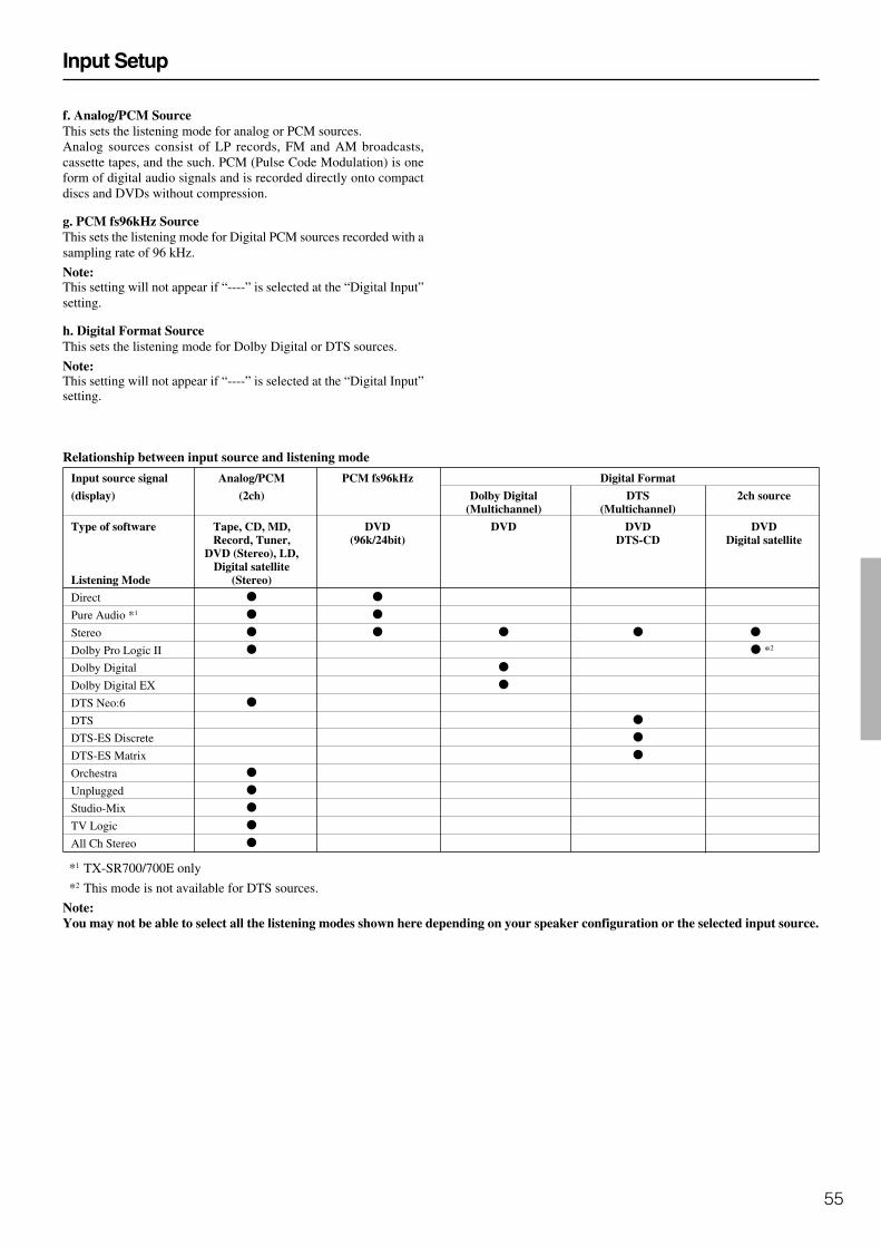
55
Relationship between input source and listening mode
Input source signal Analog/PCM PCM fs96kHz Digital Format
(display) (2ch) Dolby Digital DTS 2ch source(Multichannel) (Multichannel)
Type of software Tape, CD, MD, DVD DVD DVD DVDRecord, Tuner, (96k/24bit) DTS-CD Digital satellite
DVD (Stereo), LD,Digital satellite
Listening Mode (Stereo)
Direct o o
Pure Audio *1 o o
Stereo o o o o o
Dolby Pro Logic II o o *2
Dolby Digital o
Dolby Digital EX o
DTS Neo:6 o
DTS o
DTS-ES Discrete o
DTS-ES Matrix o
Orchestra o
Unplugged o
Studio-Mix o
TV Logic o
All Ch Stereo o
*1 TX-SR700/700E only
*2 This mode is not available for DTS sources.
Note:You may not be able to select all the listening modes shown here depending on your speaker configuration or the selected input source.
Input Setup
f. Analog/PCM SourceThis sets the listening mode for analog or PCM sources.Analog sources consist of LP records, FM and AM broadcasts,cassette tapes, and the such. PCM (Pulse Code Modulation) is oneform of digital audio signals and is recorded directly onto compactdiscs and DVDs without compression.
g. PCM fs96kHz SourceThis sets the listening mode for Digital PCM sources recorded with asampling rate of 96 kHz.
Note:This setting will not appear if “----” is selected at the “Digital Input”setting.
h. Digital Format SourceThis sets the listening mode for Dolby Digital or DTS sources.
Note:This setting will not appear if “----” is selected at the “Digital Input”setting.

56
OSD Setup and Other Settings
OSD Setup
This menu allows you to customize the OSD Setup Menu to displayin the manner you desire.
To display the OSD Setup menu:1. Display the main menu.
2. Use the and cursor buttons to select “5. OSD Setup” andthen press the ENTER button.
The “OSD Setup” menu appears.
a. Background ColorSelect either Blue, Green, Magenta, or Red as the background colorwhen the OSD Setup Menu is displayed.
b. Immediate Display
Off: Select to turn off the immediate display of operations.
Normal: Select to display operations in the bottom right cornerof a TV screen with a 4:3 aspect ratio.
Wide: Select to display operations in the bottom right corner of aTV screen with a 16:9 aspect ratio.
Hint:If this is set to “Off,” the background color will not be displayedeven when there is no video signal input.
c. TV Format(For all models other than USA and Canadian models)The default setting is “Auto,” which means that the television formatis detected and automatically set by the TX-SR700/700E/600/600E.However, if you know the correct format, you can use this setting tochoose either PAL or NTSC so that no time is wasted on detection.
VIDEO 1
d. OSD Output/ c. OSD Output (TX-SR600/600E only)Sets the OSD menu output.
VIDEO: Select this setting when the TV or projector monitor isconnected to the VIDEO OUT jack.
S VIDEO: Select this setting when the TV or projector monitoris connected to the S VIDEO OUT jack.
Preference
To display the Preference menu:1. Display the main menu.
2. Use the and cursor buttons to select “6. Preference” andthen press the ENTER button.
The “Preference” menu appears.
a. Headphones LevelYou can adjust the volume output from the headphones so that itmatches the level output from the speakers. The headphone volumecan be adjusted between –12 and +12 decibels.
b. IR IN Position (TX-SR700/700E only)Use this setting when you have a remote control sensor connected tothe IR IN terminal. The setting in this menu tells the TX-SR700/700E whether the remote control sensor is being used for operationof the TX-SR700/700E in the main zone or the remote zone (Zone2).
Main: Select when you are using the remote control sensor foroperation with the remote controller in the main zone.
Zone 2: Select when you are using the remote control sensor foroperation with the remote controller in the remote zone (Zone 2).
c. AM Frequency Step (TX-SR700/700E)/ b. AM FrequencyStep (TX-SR600/600E)This setting only appears on the worldwide model. It determines theincrement amount or decrement amount when adjusting the AMtuner frequency. The initial setting is 9 kHz, and this needs only to bechanged if you are using the TX-SR700/700E/600/600E in a 10-kHzregion.
* Menu ***************** 1.Speaker Config 2.Speaker Distance 3.Level Calibration 4.Input Setup 5.OSD Setup 6.Preference
6.Preference *********************** a.Headphones Level : 0dB b.AM Frequency Step :9 kHz
Quit:|SETUP|
db
TX-SR700/700E
TX-SR600/600E
* Menu ***************** 1.Speaker Config 2.Speaker Distance 3.Level Calibration 4.Input Setup 5.OSD Setup 6.Preference
6.Preference *********************** a.Headphones Level : 0dB b.IR IN Position :Main c.AM Frequency Step :9 kHz
Quit:|SETUP|
db
TX-SR700/700E
TX-SR600/600E
* Menu ***************** 1.Speaker Config 2.Speaker Distance 3.Level Calibration 4.Input Setup 5.OSD Setup 6.Preference
5.OSD Setup *********************** a.Background Color :Blue b.Immediate Display :Normal c.TV Format :Auto
Quit:|SETUP|
* Menu ***************** 1.Speaker Config 2.Speaker Distance 3.Level Calibration 4.Input Setup 5.OSD Setup 6.Preference
5.OSD Setup *********************** a.Background Color :Blue b.Immediate Display :Normal c.TV Format :Auto d.OSD Output :Video
Quit:|SETUP|

57
Audio Adjust
These settings are enabled depending on the listening mode or inputsignal.
Setup Procedure
1. Press the AUDIO ADJUST button.The Audio Adjust settings appear in the front display and on themonitor.
Note:The items that appear in the menu depend on the currently selectedlistening mode or the input signal. (see page 59).
2. Use the and cursor buttons to select the item thatyou want to set.
3. Use the and cursor buttons to set the value.
Setting Values Initial valueBass –12 to +12 0
Treble –12 to +12 0
Subwoofer (Analog/PCM) On, Off On
Late Night Off, Low, High Off
Center Image 0, 1, 2, 3, 4, 5 3
Panorama On, Off Off
Dimension 0, 1, 2, 3, 4, 5, 6 3
Center Width 0, 1, 2, 3, 4, 5, 6, 7 3
Front Effect* Off, Middle, High Middle
Surround Effect* Off, Middle, High Middle
* TX-SR700/700E only
Bass, TrebleSeparately adjust the bass and treble settings in 2-decibelincrements.The Bass and Treble adjustments are only enabled for the front leftand right speakers.
Note:If Direct or Pure Audio is selected as the listening mode, thesesettings cannot be made. To make these settings, first select anotherlistening mode.
SubwooferWhen “Yes” is selected for the “Subwoofer” setting in the “SpeakerConfig” menu, set this to “Off” if you do not want to have soundoutput from the subwoofer when listening to Analog/PCM sources.If “No” is selected for the “Subwoofer” setting in the “SpeakerConfig” menu, this setting will not appear.
Late NightThe audio for movies made for the cinema have a large dynamicrange; thus, the difference between loud noises and soft noises isgreat. To hear the quieter sounds such as background noises orhuman conversations, the movie must be played back at largervolumes. When this setting is set to “High” or “Low,” the dynamicrange of the sound is narrowed down to allow you to easily hearminute sounds at low volumes. This function is especially useful ifyou wish to play a movie at low volumes during the nighttime.
This can be set to either “Off” or “Low,” or “High.” When thissetting is set to “High” or “Low,” the dynamic range of the sound isnarrowed down to allow you to easily hear minute sounds at lowvolume.
Off: Select to turn off the Late Night function.
Low: Select to narrow down the dynamic range.
High: Select to further narrow down the dynamic range.
Notes:• The Late Night function is effective only on Dolby Digital
encoded software.• The depth of the Late Night effect is determined by Dolby
Digital software. With some sources, it may produce little or noeffect.
AUDIO ADJUST
///
AUDIO ADJUST
///
db
Bass : 0dB Treble : 0dB

58
Audio Adjust
Center ImageDTS Neo:6 derives a center channel from two-channel PCM andanalog sources.In cinema mode, for Lt/Rt film soundtracks, sounds steered to thecenter are subtracted from the left and right channels.In music mode, the intent in the front channels is less one of steeringand more one of stabilizing the front image by augmenting it with acenter channel, while preserving the original perspective of thestereo mix. Therefore the derived center is never fully subtractedfrom the left and right channels.
Center Image is the factor controlling the amount of subtraction. Itvaries between 0 and 5 in steps of 1 and the default value is 3.When Center Image=5, the factor is zero and nothing is subtractedfrom the left and right channels. When Center Image=0, the centerchannel is subtracted from the left and right channels at half level(–6 dB) for each channel. The signal level sent to the center channeloutput is not affected by Center Image.
This control should be set based on room layout and personalpreferences. A setting of 5 allows the left and right channels to passthrough unaltered from the stereo mix. A setting of 0 gives morecenter channel dominance, which is particularly desirable if listenersare located well off-center. At any setting, the center speaker anchorsthe image.
Center Image is only enabled when the listening mode is DTS Neo:6Music.
Pro Logic II Music Panorama (Panorama)Use this setting to extend the front stereo image to include thesurround speakers for an exciting wraparound effect with side wallimaging.
On: Select to turn on the PL II Music Panorama mode.
Off: Select to turn off the PL II Music Panorama mode.
Panorama is only enabled when the listening mode is Dolby ProLogic II Music.
Pro Logic II Music Dimension (Dimension)Use this setting to gradually adjust the soundfield forward orbackward. The setting of “3” is the normal position. Change thesetting to “2” or lower to move the sound space forward setting to“4” or higher to move the sound space backward.If the stereo recording has excessive broadness or too strongsurroundness, move the sound space forward to get the appropriatesound balance. In contrast, if the stereo recording is somewhat feltlike monaural or has narrowness, move the sound space backward toget more surroundness.
Dimension is only enabled when the listening mode is Dolby ProLogic II Music.
Pro Logic II Music Center Width (Center Width)In Pro Logic II decoding, center signals are output from the centerspeaker. When the center speaker is not used, the decoder will dividethe center signal equally to both the front left and right speakers tocreate a “phantom” center sound image.The Pro Logic II Music Center Width mode allows you to adjustfrom where the center sound image is heard. Using this, you canhave the soundfield be heard from the center speaker only, from thefront left and right speakers only (as a phantom center sound image),or from all three speakers (center, front left and right) in variouslevel combinations. For home use, applying some width to the centersignal will improve the level balance for the center and mainspeakers, and effect the width of the center sound image, or “weight”of the sound. Many sound recordings processed for stereo playbackwill be reproduced better by proper control of this setting. Therecommended setting for Pro Logic II Music mode is “3.” Thisallows you to easily distinguish the Pro Logic II Music mode fromthe Pro Logic II Movie mode whose setting is automatically set to“0.”Center Width is only enabled when the listening mode is Dolby ProLogic II Music.
Front Effect (TX-SR700/700E only)Some live recordings contain acoustic reverberation. When you playthese sources, more reverberation will be applied by the DSP,creating too much reverb effects and the sound loses frame orpresence. In this case, set this setting to “Off” so that noreverberation from the DSP will be applied to the sound output fromthe three front channels. With this setting, the sound source is playedas it is without any further reverberation.Front Effect is only enabled when the listening mode is Orchestra,Unplugged, Studio Mix, or TV Logic.
Surround Effect (TX-SR700/700E only)You can choose from “Off,” “Middle,” or “High.”This adjusts the reflected and residual noises from the surround leftand right speakers and surround back speaker.Surround Effect is only enabled when the listening mode isOrchestra, Unplugged, Studio Mix, or TV Logic.

59
Audio Adjust
Settings possible for each listening mode
Setting Tone Subwoofer LATE Center Panorama, Front SurroundControl (Analog/ NIGHT Image Dimension, Effect Effect(Bass, PCM only) CenterTreble Width
Listening mode
Direct
Pure Audio
Stereo
Dolby Pro Logic II *1 *3
Dolby Digital
Dolby Digital EX
DTS Neo:6 *2
DTS
DTS-ES Discrete
DTS-ES Matrix
Orchestra
Unplugged
Studio-Mix
TV Logic
All CH Stereo
*1 Enabled for a Dolby Digital input source.
*2 Enabled for a DTS Neo:6 Music input source.
*3 Enabled for a Dolby Pro Logic II Music source.
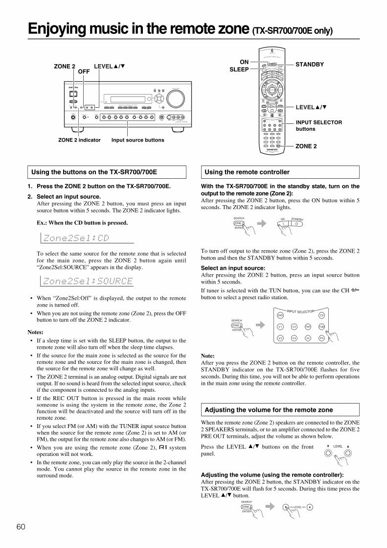
60
Using the remote controller
With the TX-SR700/700E in the standby state, turn on theoutput to the remote zone (Zone 2):After pressing the ZONE 2 button, press the ON button within 5seconds. The ZONE 2 indicator lights.
To turn off output to the remote zone (Zone 2), press the ZONE 2button and then the STANDBY button within 5 seconds.
Select an input source:After pressing the ZONE 2 button, press an input source buttonwithin 5 seconds.
If tuner is selected with the TUN button, you can use the CH button to select a preset radio station.
Note:After you press the ZONE 2 button on the remote controller, theSTANDBY indicator on the TX-SR700/700E flashes for fiveseconds. During this time, you will not be able to perform operationsin the main zone using the remote controller.
Adjusting the volume for the remote zone
When the remote zone (Zone 2) speakers are connected to the ZONE2 SPEAKERS terminals, or to an amplifier connected to the ZONE 2PRE OUT terminals, adjust the volume as shown below.
Press the LEVEL / buttons on the frontpanel.
Adjusting the volume (using the remote controller):After pressing the ZONE 2 button, the STANDBY indicator on theTX-SR700/700E will flash for 5 seconds. During this time press theLEVEL / button.
OFFZONE 2
ON
ZONE 2
SLEEP
LEVEL /
STANDBYLEVEL /
Enjoying music in the remote zone (TX-SR700/700E only)
Using the buttons on the TX-SR700/700E
1. Press the ZONE 2 button on the TX-SR700/700E.
2. Select an input source.After pressing the ZONE 2 button, you must press an inputsource button within 5 seconds. The ZONE 2 indicator lights.
Ex.: When the CD button is pressed.
To select the same source for the remote zone that is selectedfor the main zone, press the ZONE 2 button again until“Zone2Sel:SOURCE” appears in the display.
• When “Zone2Sel:Off” is displayed, the output to the remotezone is turned off.
• When you are not using the remote zone (Zone 2), press the OFFbutton to turn off the ZONE 2 indicator.
Notes:• If a sleep time is set with the SLEEP button, the output to the
remote zone will also turn off when the sleep time elapses.
• If the source for the main zone is selected as the source for theremote zone and the source for the main zone is changed, thenthe source for the remote zone will change as well.
• The ZONE 2 terminal is an analog output. Digital signals are notoutput. If no sound is heard from the selected input source, checkif the component is connected to the analog inputs.
• If the REC OUT button is pressed in the main room whilesomeone is using the system in the remote zone, the Zone 2function will be deactivated and the source will turn off in theremote zone.
• If you select FM (or AM) with the TUNER input source buttonwhen the source for the remote zone (Zone 2) is set to AM (orFM), the output for the remote zone also changes to AM (or FM).
• When you are using the remote zone (Zone 2), systemoperation will not work.
• In the remote zone, you can only play the source in the 2-channelmode. You cannot play the source in the remote zone in thesurround mode.
ZONE 2 indicator Input source buttons
INPUT SELECTORbuttons

61
Recording the video from one source and the audio fromanother:
You can add the sound from one source to the video of anothersource to make your own video recordings.Below is an example of recording the sound from a compact discplayer connected to CD IN and the video from a video cameraconnected to VIDEO 4 INPUT to a video cassette tape in a videocassette recorder connected to the VIDEO 1 OUT jack.
1. Press the VIDEO 4 input source button.
2. Press the CD input source button.
3. Insert a CD in the CD player and insert a tape in the videocamera connected to the VIDEO 4 INPUT.
4. Insert a video tape for recording in the video cassetterecorder connected to VIDEO 1 OUT.
5. From this step on, follow the same procedures described in 2and 3 above.
To record an input source signal different from thatyou are currently watching or listening to
Follow the procedure given below to record an input source signaldifferent from that which you are listening to or watching at the timeof recording.
1. Press the REC OUT button.
2. Within 5 seconds, press the input source selectorbutton of the input source signal that you wish torecord.
The signal from the selected input source is now output to theTAPE OUT, VIDEO 1 OUT, and VIDEO 2 OUT outputs forrecording.
3. Start recording at the recording component asdesired.
To confirm the settings, press the REC OUT button. The currentsettings will appear for 5 seconds in the front display.
Notes:
• Be aware that the remote (Zone 2) and recording (REC OUT)outputs use the same circuit and therefore cannot be used at thesame time.
• If you select FM (or AM) with the TUNER input source buttonwhen the recording source is set to AM (or FM), the output forthe recording source also changes to AM (or FM).
Recording a source (TX-SR700/700E)
REC OUT
Notes:• You cannot record the surround effects.
• Digital signals input to the DIGITAL INPUT (COAXIAL) andDIGITAL INPUT (OPTICAL) inputs will be output to theDIGITAL OUTPUT (COAXIAL) and DIGITAL OUTPUT(OPTICAL) output.
• There are some restrictions on recording digital signals. Whenmaking digital recordings, consult the instruction manual thatcame with your digital recording equipment (e.g., MD recorderor DAT deck) to know what restrictions are imposed.
• You cannot record the source connected to the 5.1-channel inputjacks.
• If you change the input source during recording, you will recordthe signals from the newly selected input source.
• Digital input signals are only output to the digital outputs andanalog input signals are only output to the analog outputs. Thereis no conversion from digital to analog or vice versa. Whenconnecting CD players and other digital components, do notconnect only the digital terminals, but the analog ones as well.
To record the input source signal you are currentlywatching or listening to
This method outputs to the audio and video outputs the currentlyselected input source signal. This method allows you to a signalwhile you are actually listening to or watching it.
1. Select the input source to record by pressing thecorresponding input source button.
The input source is now selected and you may watch or listen toit as desired.
2. Press the REC OUT button repeatedly until “RecSel:SOURCE” appears in the front display.
The signal from the currently selected input source is now outputto the TAPE OUT, VIDEO 1 OUT, and VIDEO 2 OUT outputsfor recording.
3. Start recording at the recording component asdesired.
To confirm the settings, press the REC OUT button. The currentsettings will appear for 3 seconds in the front display.
Input source buttons

62
Recording a source (TX-SR600/600E)
Notes:• You cannot record the surround effects.
• Digital signals input to the DIGITAL INPUT (COAXIAL) andDIGITAL INPUT (OPTICAL) inputs will be only output to theDIGITAL OUTPUT (OPTICAL) output.
• There are some restrictions on recording digital signals. Whenmaking digital recordings, consult the instruction manual thatcame with your digital recording equipment (e.g., MD recorderor DAT deck) to know what restrictions are imposed.
• You cannot record the source connected to the 5.1-channel inputjacks.
• If you change the input source during recording, you will recordthe signals from the newly selected input source.
• Digital input signals are only output to the digital outputs andanalog input signals are only output to the analog outputs. Thereis no conversion from digital to analog or vice versa. Whenconnecting CD players and other digital components, do notconnect only the digital terminals, but the analog ones as well.
To record the input source signal you are currentlywatching or listening to
This method outputs to the audio and video outputs the currentlyselected input source signal. This method allows you to a signalwhile you are actually listening to or watching it.
1. Insert a media for recording into the recordingcomponent (cassette tape deck, video deck, or MDrecorder).
2. Select the input source to record by pressing thecorresponding input source button.
3. Start the output source component and startrecording at the recording component as desired.
Input source buttons
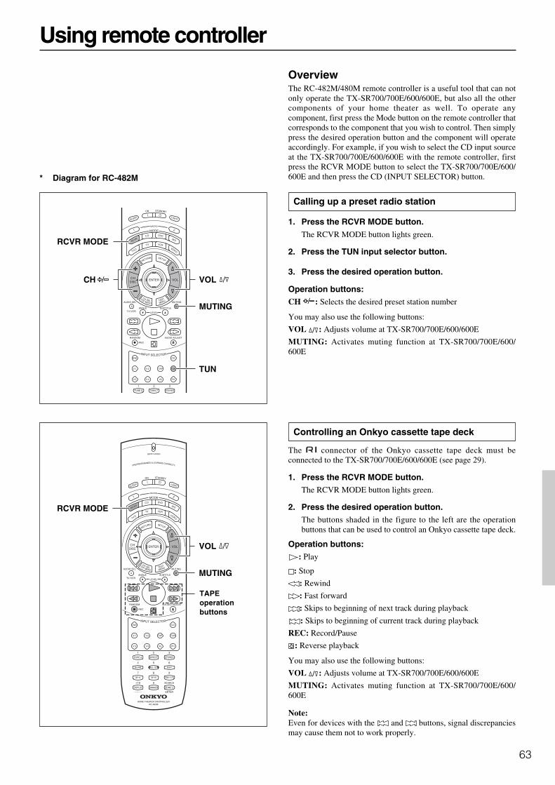
63
Using remote controller
TAPEoperationbuttons
RCVR MODE
TUN
CH VOL
MUTING
RCVR MODE
VOL
MUTING
OverviewThe RC-482M/480M remote controller is a useful tool that can notonly operate the TX-SR700/700E/600/600E, but also all the othercomponents of your home theater as well. To operate anycomponent, first press the Mode button on the remote controller thatcorresponds to the component that you wish to control. Then simplypress the desired operation button and the component will operateaccordingly. For example, if you wish to select the CD input sourceat the TX-SR700/700E/600/600E with the remote controller, firstpress the RCVR MODE button to select the TX-SR700/700E/600/600E and then press the CD (INPUT SELECTOR) button.
Calling up a preset radio station
1. Press the RCVR MODE button.
The RCVR MODE button lights green.
2. Press the TUN input selector button.
3. Press the desired operation button.
Operation buttons:CH : Selects the desired preset station number
You may also use the following buttons:
VOL : Adjusts volume at TX-SR700/700E/600/600E
MUTING: Activates muting function at TX-SR700/700E/600/600E
Controlling an Onkyo cassette tape deck
The connector of the Onkyo cassette tape deck must beconnected to the TX-SR700/700E/600/600E (see page 29).
1. Press the RCVR MODE button.The RCVR MODE button lights green.
2. Press the desired operation button.The buttons shaded in the figure to the left are the operationbuttons that can be used to control an Onkyo cassette tape deck.
Operation buttons:: Play
: Stop
: Rewind
: Fast forward
: Skips to beginning of next track during playback
: Skips to beginning of current track during playback
REC: Record/Pause
: Reverse playback
You may also use the following buttons:
VOL : Adjusts volume at TX-SR700/700E/600/600E
MUTING: Activates muting function at TX-SR700/700E/600/600E
Note:Even for devices with the and buttons, signal discrepanciesmay cause them not to work properly.
* Diagram for RC-482M

64
Controlling an Onkyo CD player
The connector of the Onkyo compact disc player must beconnected to the TX-SR700/700E/600/600E (see page 29).
1. Press the CD MODE button.The CD MODE button lights green.
2. Press the desired operation button.The buttons shaded in the figure to the left are the operationbuttons that can be used to control an Onkyo compact discplayer.
Operation buttons:ON: Turns on and off the compact disc player (same as theSTANDBY button on the remote controller)
DISC : Selects disc in CD changer
: Track down
: Track up
: Play
: Stop
: Skip backward
: Skip forward
: Pause
OPEN/CLOSE : Opens/closes disc tray
0, 1 to 9, +10: Numeric keys
RANDOM: Random playback
You may also use the following buttons:
VOL : Adjusts volume at TX-SR700/700E/600/600E
MUTING: Activates muting function at TX-SR700/700E/600/600E
CDoperationbuttons
Numeric keys
Using remote controller
CD MODE
VOL
MUTING
ON STANDBY
DISC

65
Using remote controller
Controlling an Onkyo DVD player
The connector of the Onkyo DVD player must be connected tothe TX-SR700/700E/600/600E (see page 29).
1. Press the DVD MODE button.The DVD MODE button lights green.
2. Press the desired operation button.The buttons shaded in the figure to the left are the operationbuttons that can be used to control an Onkyo DVD player.
Operation buttons:ON: Turns DVD player on and off
STANDBY: Turns DVD player off (Some sets may not respond tothis button. In this case, use the ON button to put the DVD player inthe standby state.)
SETUP: Displays OSD Menu of the DVD player
: Moves cursor in the OSD Menu of the DVD player
ENTER: Enter button for the OSD Menu of the DVD player
RETURN: Return button for the OSD Menu of the DVD player
TOP MENU or MENU: Displays menu screens recorded on DVDmedia
DISC : Selects disc in DVD changer
AUDIO SEL: Selects audio or language track (if recorded on theDVD)
ANGLE: Selects camera angle (if recorded on the DVD)
SUBTITLE: Selects subtitle language (if recorded on the DVD)
SEARCH: Searches for location on disc to start playback
RANDOM: Random playback
: Chapter/Track down
: Chapter/Track up
: Play
: Stop
: Fast reverse
: Fast forward
: Pause
OPEN/CLOSE : Opens/closes disc tray
0, 1 to 9, +10: Numeric keys
You may also use the following buttons:
VOL : Adjusts volume at TX-SR700/700E/600/600E
MUTING: Activates muting function at TX-SR700/700E/600/600E
Note:When operating an Onkyo DVD player directly with the remotecontroller without connecting the terminals, pre-programming isnecessary (see page 67).
DVDoperationbuttons
Numeric keys
VOL
MUTING
ON STANDBY
DVD MODE
SUBTITLE
TOP MENU
RETURN
AUDIO SEL
ANGLE
ENTER,
SEARCH
SETUP
MENU
DISC
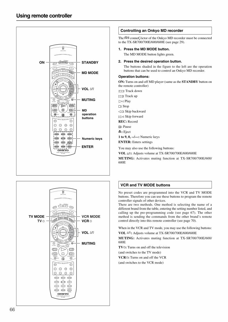
66
Controlling an Onkyo MD recorder
The conneÇóctor of the Onkyo MD recorder must be connectedto the TX-SR700/700E/600/600E (see page 29).
1. Press the MD MODE button.The MD MODE button lights green.
2. Press the desired operation button.The buttons shaded in the figure to the left are the operationbuttons that can be used to control an Onkyo MD recorder.
Operation buttons:ON: Turns on and off MD player (same as the STANDBY button onthe remote controller)
: Track down
: Track up
: Play
: Stop
: Skip backward
: Skip forward
REC: Record
: Pause
: Eject
1 to 9, 0, --/---: Numeric keys
ENTER: Enters settings
You may also use the following buttons:
VOL : Adjusts volume at TX-SR700/700E/600/600E
MUTING: Activates muting function at TX-SR700/700E/600/600E
VCR and TV MODE buttons
No preset codes are programmed into the VCR and TV MODEbuttons. Therefore you can use these buttons to program the remotecontroller signals of other devices.There are two methods. One method is selecting the name of adifferent brand from the table, entering the setting number listed, andcalling up the pre-programming code (see page 67). The othermethod is sending the commands from the other brand’s remotecontrol directly into this remote controller (see page 70).
When in the VCR and TV mode, you may use the following buttons:
VOL : Adjusts volume at TX-SR700/700E/600/600E
MUTING: Activates muting function at TX-SR700/700E/600/600E
TV : Turns on and off the television
(and switches to the TV mode)
VCR : Turns on and off the VCR
(and switches to the VCR mode)
MDoperationbuttons
Numeric keys
Using remote controller
MD MODE
VOL
MUTING
ON STANDBY
ENTER
VOL
MUTING
VCR MODETV MODETV VCR
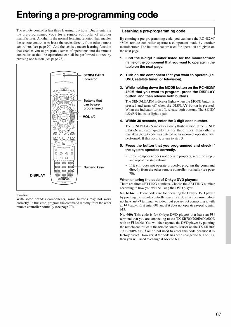
67
Entering a pre-programming code
SEND/LEARNindicator
Numeric keys
Buttons thatcan be pre-programmed
The remote controller has three learning functions. One is enteringthe pre-programmed code for a remote controller of anothermanufacturer. Another is the normal learning function that enablesthe remote controller to learn the codes directly from other remotecontrollers (see page 70). And the last is a macro learning functionthat enables you to program a series of operations into the remotecontroller so that the operations can all be performed at once bypressing one button (see page 73).
Caution:With some brand’s components, some buttons may not workcorrectly. In this case, program the command directly from the otherremote controller normally (see page 70).
VOL
DISPLAY
Learning a pre-programming code
By entering a pre-programming code, you can have the RC-482M/480M remote controller operate a component made by anothermanufacturer. The buttons that are used for operation are given onthe next page.
1. Find the 3-digit number listed for the manufacturername of the component that you want to operate in thetable on the next page.
2. Turn on the component that you want to operate (i.e.DVD, satellite tuner, or television).
3. While holding down the MODE button on the RC-482M/480M that you want to program, press the DISPLAYbutton, and then release both buttons.The SEND/LEARN indicator lights when the MODE button ispressed and turns off when the DISPLAY button is pressed.When the indicator turns off, release both buttons. The SEND/LEARN indicator lights again.
4. Within 30 seconds, enter the 3-digit code number.The SEND/LEARN indicator slowly flashes twice. If the SEND/LEARN indicator quickly flashes three times, then either amistaken 3-digit code was entered or an incorrect operation wasperformed. If this occurs, return to step 3.
5. Press the button that you programmed and check ifthe system operates correctly.
• If the component does not operate properly, return to step 3and repeat the steps above.
• If it still does not operate properly, program the commanddirectly from the other remote controller normally (see page70).
When entering the code of Onkyo DVD players:There are three SETTING numbers. Choose the SETTING numberaccording to how you will be using the DVD player.
No. 601/613: These codes are for operating the Onkyo DVD playerby pointing the remote controller directly at it, either because it doesnot have an terminal, or it does but you are not connecting it withan cable. First enter 601 and if it does not operate properly, enter613.
No. 600: This code is for Onkyo DVD players that have an terminal that you are connecting to the TX-SR700/700E/600/600Ewith an cable. You will then operate the DVD player by pointingthe remote controller at the remote control sensor on the TX-SR700/700E/600/600E. You do not need to enter this code because it isfactory preset. However, if the code has been changed to 601 or 613,then you will need to change it back to 600.

68
Pre-programming codes
Note:If more than one code is given in the table,try each code one by one until you reach acode that works (i.e. if the first code doesnot work, then try the next).
DVDBRAND SETTING No.DENON 602, 609HITACHI 603JVC 604KENWOOD 605MAGNAVOX 606, 613MARANTZ 607MITSUBISHI 608, 613ONKYO 600, 601, 613PANASONIC 609PIONEER 610PROSCAN 611RCA 611SONY 612TOSHIBA 613YAMAHA 609, 614ZENITH 613, 615
VCRBRAND SETTING No.AIWA 300, 301, 302AKAI 303, 304, 305, 306,
307BAIRD 308BELL & HOWELL 309BLAUPUNKT 310CGM 311, 312, 313COLTINA 314DAEWOO 315, 316DIGITAL 317EMERSON 318, 319, 320, 321,
322FENNER 323FISHER 324, 325, 326, 327
FUJITSU GENERAL 328FUNAI 329GE 330, 331GO VIDEO 332, 336, 337GOLDSTAR 333, 334GOODMANS 335GRUNDIG 338HITACHI 331, 339, 340, 341,
382JVC 342, 343, 344, 345,
346, 347, 348, 349,350
LOEWE 351, 352MAGNAVOX 353, 354, 355MITSUBISHI 356, 357, 358, 359,
360, 361, 362, 363,364
NEC 365, 366, 367NOKIA 313NORDMENDE 368, 369, 370OKANO 371, 372ORION 319, 373PANASONIC 374, 375, 376, 377,
378PHILIPS 353, 379, 380PHONOLA 311PIONEER 381
Entering a pre-programming code
RCA 382SABA 383SAMSUNG 384, 385, 386, 387,
388, 389, 390SANYO 391, 392, 393SCOTT 394SELECO 395SHARP 396, 397, 398, 399SHINTOM 400SIEMENS 401SONY 402, 403, 404, 405,
406, 407, 408, 409,410, 411, 412, 413,423
SYMPHONIC 414TEKNIKA 414, 415TELEFUNKEN 416, 417TOSHIBA 418, 419, 420WHITEWESTINGHOUSE 333WATSON 421ZENITH 422
TVBRAND SETTING No.AIWA 100, 101AKAI 102, 103, 104AUDIOSONIC 105BELL & HOWELL 106BLAUPUNKT 107BRIONVEGA 108, 109CENTURION 110COLTINA 111, 112, 113CORONAD 114CROWN 115, 116DAEWOO 117, 118, 119, 120,
121DUAL 122EMERSON 123, 124, 125, 126,
127FENNER 128, 129FERGUSON 130, 131FISHER 132FUNAI 133, 134, 135FUJITSU GENERAL 136, 137, 138GE 139, 140, 141GOLDSTAR 142, 143GOODMANS 144GRUNDIG 145, 146HITACHI 147, 148, 149, 150HYPER 151INNO HIT 152IRRADIO 103JVC 153, 154, 155, 156,
157KENDO 158KTV 159, 160LUXOR 161MAGNAVOX 162, 163MARANTZ 164MARK 165MATSUI 166, 167, 168, 169MITSUBISHI 170, 171, 172, 173MIVAR 174, 175NEC 176, 177NOKIA 178, 179, 180, 181OCEANIC 181NORDMENDE 182, 183OKANO 152ORION 184, 185, 186PANASONIC 187, 188, 189, 190
PHILIPS 152, 162, 191PIONEER 192, 193PROSCAN 194QUASAR 195RADIO SHACK 196RCA 110, 141, 197, 198,
199, 200SABA 182, 183, 201SAMSUNG 202, 203, 204, 205,
206, 207, 208SANYO 209, 210, 211, 212SCHNEIDER 103SEARS 213SELECO 214, 215SHARP 216, 217SONY 218, 219, 220, 221,
222, 223SYMPHONIC 224, 225TELEFUNKEN 201, 226, 227THOMSON 228TOSHIBA 213, 229UNIVERSUM 230ZENITH 231, 232
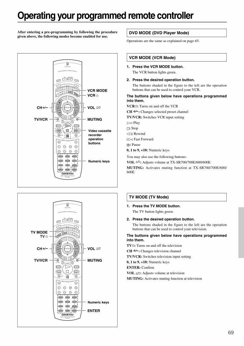
69
Numeric keys
Numeric keys
Video cassetterecorderoperationbuttons
Operating your programmed remote controllerAfter entering a pre-programming by following the proceduregiven above, the following modes become enabled for use.
DVD MODE (DVD Player Mode)
Operations are the same as explained on page 65.
VCR MODE (VCR Mode)
1. Press the VCR MODE button.The VCR button lights green.
2. Press the desired operation button.The buttons shaded in the figure to the left are the operationbuttons that can be used to control your VCR.
The buttons given below have operations programmedinto them.VCR : Turns on and off the VCR
CH : Changes selected preset channel
TV/VCR: Switches VCR input setting
: Play
: Stop
: Rewind
: Fast Forward
: Pause
0, 1 to 9, +10: Numeric keys
You may also use the following buttons:
VOL : Adjusts volume at TX-SR700/700E/600/600E
MUTING: Activates muting function at TX-SR700/700E/600/600E
TV MODE (TV Mode)
1. Press the TV MODE button.The TV button lights green.
2. Press the desired operation button.The buttons shaded in the figure to the left are the operationbuttons that can be used to control your television.
The buttons given below have operations programmedinto them.TV : Turns on and off the television
CH : Changes television channel
TV/VCR: Switches television input setting
0, 1 to 9, +10: Numeric keys
ENTER: Confirm
VOL : Adjusts volume at television
MUTING: Activates muting function at television
VOL
MUTING
VCR MODE
TV/VCR
CH
VCR
VOL
MUTINGTV/VCR
CH
TV MODE
ENTER
TV

70
Programming the commands of remote controllers forother devices into the remote controller
2 to 6 inches(5 to 15 cm )
Buttons that cannot be programmed.
SEND/LEARNindicator
MODEbuttons
MODE buttons
Programming procedure
When programming the commands of another remote controller tothe RC-482M/480M remote controller, you must first decide underwhich MODE button you want the commands to be linked. Ingeneral, you will select the MODE button that corresponds to thecomponent you are programming. For example, if you areprogramming the functions from a remote controller for a compactdisc player, you would choose the CD MODE button. Then, bypressing the CD MODE button, the buttons on the RC-482M/480Mremote controller will change to the commands you program here tooperate the compact disc player.After programming which MODE button to use, you will thentransfer the separate commands from the other remote controllerover to the RC-482M/480M remote controller one at a time. Eachcommand is then programmed to a different button on the RC-482M/480M remote controller. Any button is programmable for thisstep except for the six MODE buttons (RCVR, CD, DVD, MD, TV,and VCR), the two MACRO buttons (MACRO 1 and 2), and theLIGHT button (RC-482M only).Even after the commands have been memorized, keep your oldremote controller in a safe place. If for some reason the commandsare lost (e.g., when the batteries run down), it will be necessary tomemorize them once again.
1. Place the remote controller and the remote controllerfor the other device facing each other at a distance of 2to 6 inches (5 to 15 cm) apart.
2. While pressing and holding down the desired MODEbutton on the remote controller, press the ENTERbutton and then release both buttons.The SEND/LEARN indicator lights when the MODE button ispressed and turns off when the ENTER button is pressed. Whenthe indicator turns off, release both buttons. The SEND/LEARNindicator lights again.
3. Press and release the button on the remote controllerto which you want to transfer the next command.You may select any button excluding the eleven ones indicatedin the figure below. When you press the button, the SEND/LEARN indicator turns off. When you release the button, theindicator lights again.If you press the wrong button by mistake, press that same buttonagain. The SEND/LEARN indicator flashes twice, and theremote controller exits the programming mode.
POWER
SLEEPDIM
MERSUR
MODE
VIDEO-1
VIDEO-2
TAPE
DVD
C D
C D
DVD
TUNER
TUNER
PHONO
INPUT S
ELECTOR
DISC
TAPE
VOLUME
CH SEL
PRESET
MUTING
TESTTONE
MULTI-CH
INPUT
GROUP
85S
ENTER
MACRO 1 MACRO 2
LIGHT
:
(RC-482M only)

71
Programming the commands of remote controllers for other devices into the remotecontroller
4. Press and hold down the button (that corresponds tothe command you are programming) on the remotecontroller of the other device until the SEND/LEARNlamp on the remote controller flashes twice.After flashing twice, the SEND/LEARN indicator will lightagain.
5. Repeat Steps 3 and 4 to transfer all the commands youdesire from the other remote controller and programthem to buttons on the remote controller under thesame MODE.
Repeat Steps 2 through 4 to program commands to a differentMODE (e.g., when programming from a different remotecontroller).
6. Press the MODE button that you pressed in step 2 tocomplete the programming.
7. Operate the newly programmed buttons to make surethe learning function was performed properly.
Notes:• The remote controller codes for Onkyo compact disc players,
cassette tape decks, DVD players, and mini disc recorder havealready been programmed into buttons on the remote controller.You may, however, use these buttons to program the codes forother remote controllers. If you wish to restore the Onkyo presetcodes after you program new codes, you must first erase the newcodes (see page 72).
• The remote controller has 318 memory slots (6 modes × 53buttons). Some remote controllers may have more commandsthat can be remembered by the remote controller. In such cases,it will be necessary for you to determine which commands aremore important than others.
• If the SEND/LEARN indicator quickly flashes three times andturns off, then the remote controller has exited the programmingmode because either you have made a mistake duringprogramming or a time-out has occurred because no button hasbeen pressed. Resume from Step 2.
• If you try to program beyond the learning capacity of the remotecontroller, the SEND/LEARN indicator flashes six timesquickly, and the remote controller exits the programming mode.Try programming under a different MODE button.
• When you want to program a command to a button to which youhave already programmed a command, simply follow the sameprocedure given and the previous programming for that buttonwill be overwritten.
• The remote controller uses infrared rays to send its commands,as do most other remote controllers. Though most remotecontroller codes can be memorized by the remote controller, beaware that some remote controllers use systems that are quitedifferent from the remote controller and therefore may not beable to be programmed.
• Some remote controllers have a single button that performsmultiple functions (for example, the function may change eachtime the button is pressed). If this is the case, each function mustbe programmed to a separate button on the remote controller.
• Once you have transferred the commands from the other remotecontroller, refer to the instruction manual that came with thatproduct for instructions on how to operate that product.
• Make sure both the remote controller and the other remotecontroller have new batteries. If either of them has batteries thatare low, you may not be able to program the commands of theother remote controller properly into the remote controller.
See page 72 for how to erase the memorized commands from allbuttons.
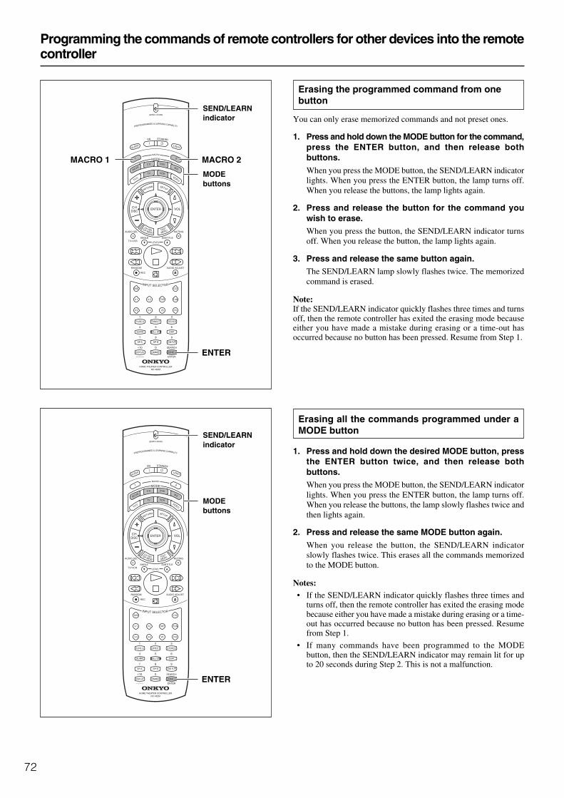
72
Programming the commands of remote controllers for other devices into the remotecontroller
SEND/LEARNindicator
MODEbuttons
SEND/LEARNindicator
MODEbuttons
Erasing the programmed command from onebutton
You can only erase memorized commands and not preset ones.
1. Press and hold down the MODE button for the command,press the ENTER button, and then release bothbuttons.
When you press the MODE button, the SEND/LEARN indicatorlights. When you press the ENTER button, the lamp turns off.When you release the buttons, the lamp lights again.
2. Press and release the button for the command youwish to erase.When you press the button, the SEND/LEARN indicator turnsoff. When you release the button, the lamp lights again.
3. Press and release the same button again.The SEND/LEARN lamp slowly flashes twice. The memorizedcommand is erased.
Note:If the SEND/LEARN indicator quickly flashes three times and turnsoff, then the remote controller has exited the erasing mode becauseeither you have made a mistake during erasing or a time-out hasoccurred because no button has been pressed. Resume from Step 1.
Erasing all the commands programmed under aMODE button
1. Press and hold down the desired MODE button, pressthe ENTER button twice, and then release bothbuttons.When you press the MODE button, the SEND/LEARN indicatorlights. When you press the ENTER button, the lamp turns off.When you release the buttons, the lamp slowly flashes twice andthen lights again.
2. Press and release the same MODE button again.
When you release the button, the SEND/LEARN indicatorslowly flashes twice. This erases all the commands memorizedto the MODE button.
Notes:• If the SEND/LEARN indicator quickly flashes three times and
turns off, then the remote controller has exited the erasing modebecause either you have made a mistake during erasing or a time-out has occurred because no button has been pressed. Resumefrom Step 1.
• If many commands have been programmed to the MODEbutton, then the SEND/LEARN indicator may remain lit for upto 20 seconds during Step 2. This is not a malfunction.
ENTER
MACRO 2MACRO 1
ENTER
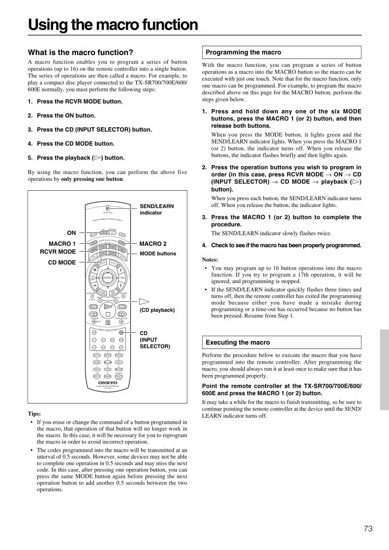
73
Using the macro function
What is the macro function?A macro function enables you to program a series of buttonoperations (up to 16) on the remote controller into a single button.The series of operations are then called a macro. For example, toplay a compact disc player connected to the TX-SR700/700E/600/600E normally, you must perform the following steps:
1. Press the RCVR MODE button.
2. Press the ON button.
3. Press the CD (INPUT SELECTOR) button.
4. Press the CD MODE button.
5. Press the playback ( ) button.
By using the macro function, you can perform the above fiveoperations by only pressing one button.
Tips:• If you erase or change the command of a button programmed in
the macro, that operation of that button will no longer work inthe macro. In this case, it will be necessary for you to reprogramthe macro in order to avoid incorrect operation.
• The codes programmed into the macro will be transmitted at aninterval of 0.5 seconds. However, some devices may not be ableto complete one operation in 0.5 seconds and may miss the nextcode. In this case, after pressing one operation button, you canpress the same MODE button again before pressing the nextoperation button to add another 0.5 seconds between the twooperations.
(CD playback)
CD(INPUTSELECTOR)
MODE buttons
ON
MACRO 2MACRO 1
CD MODE
RCVR MODE
Programming the macro
With the macro function, you can program a series of buttonoperations as a macro into the MACRO button so the macro can beexecuted with just one touch. Note that for the macro function, onlyone macro can be programmed. For example, to program the macrodescribed above on this page for the MACRO button, perform thesteps given below.
1. Press and hold down any one of the six MODEbuttons, press the MACRO 1 (or 2) button, and thenrelease both buttons.
When you press the MODE button, it lights green and theSEND/LEARN indicator lights. When you press the MACRO 1(or 2) button, the indicator turns off. When you release thebuttons, the indicator flashes briefly and then lights again.
2. Press the operation buttons you wish to program inorder (in this case, press RCVR MODE → ON → CD(INPUT SELECTOR) → CD MODE → playback ( )button).When you press each button, the SEND/LEARN indicator turnsoff. When you release the button, the indicator lights.
3. Press the MACRO 1 (or 2) button to complete theprocedure.The SEND/LEARN indicator slowly flashes twice.
4. Check to see if the macro has been properly programmed.
Notes:• You may program up to 16 button operations into the macro
function. If you try to program a 17th operation, it will beignored, and programming is stopped.
• If the SEND/LEARN indicator quickly flashes three times andturns off, then the remote controller has exited the programmingmode because either you have made a mistake duringprogramming or a time-out has occurred because no button hasbeen pressed. Resume from Step 1.
Executing the macro
Perform the procedure below to execute the macro that you haveprogrammed into the remote controller. After programming themacro, you should always run it at least once to make sure that it hasbeen programmed properly.
Point the remote controller at the TX-SR700/700E/600/600E and press the MACRO 1 (or 2) button.It may take a while for the macro to finish transmitting, so be sure tocontinue pointing the remote controller at the device until the SEND/LEARN indicator turns off.
SEND/LEARNindicator

74
MODE buttons
ENTER
MACRO 2MACRO 1
Erasing a macro from the MACRO 1 (or 2) button
1. Press and hold down any one of the six MODEbuttons, press the MACRO 1 (or 2) button, and thenrelease both buttons.
When you press the MODE button, it lights green and theSEND/LEARN indicator lights. When you press the MACRO 1(or 2) button, the indicator turns off. When you release thebuttons, the indicator flashes once.
2. Press the MACRO 1 (or 2) button again.The SEND/LEARN indicator slowly flashes twice. The macroprogrammed to the MACRO button is erased.
Notes:• If the SEND/LEARN indicator quickly flashes three times and
turns off, then the remote controller has exited the erasing modebecause either you have made a mistake during erasing or a time-out has occurred because no button has been pressed. Resumefrom Step 1.
• If you press a button other than MACRO 1 (or 2) button in Step2, then you will in effect be overwriting the previous macro witha new macro.
Using the macro function
Erasing all commands and macros that havebeen programmed
This procedure will erase all the commands and macros that youhave programmed into the remote controller and return it to itsdefault settings. This operation will not affect the preset settings ofthe remote controller.
1. Open the battery cover and remove the batteries fromthe remote controller.
2. While pressing and holding down the ON andSTANDBY buttons, re-insert the batteries in theircorrect orientation, and then release both buttons.The SEND/LEARN indicator flashes slowly.
3. Press the ENTER button.The SEND/LEARN indicator lights up for about ten seconds andthen turns off.
All programmed commands and macros are erased and the remotecontroller returns to its factory presets.
Notes:• Proceed to Step 3 immediately after Step 2; otherwise, the
batteries will be consumed quickly.
• If you press any button other than the ENTER button in Step 3,nothing will be erased. In this case, resume from Step 1.
ON
ENTER
STANDBY
SEND/LEARNindicator
SEND/LEARNindicator
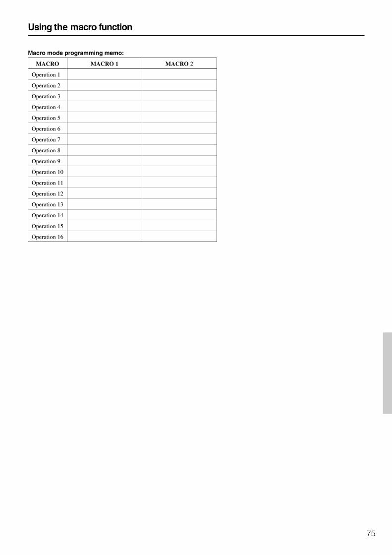
75
Macro mode programming memo:
MACRO MACRO 1 MACRO 2
Operation 1
Operation 2
Operation 3
Operation 4
Operation 5
Operation 6
Operation 7
Operation 8
Operation 9
Operation 10
Operation 11
Operation 12
Operation 13
Operation 14
Operation 15
Operation 16
Using the macro function

76
Troubleshooting guideIf a problem occurs while you are using the remote controller, firsttry to operate the controls on the front panel of the TX-SR700/700E/600/600E to make sure that it is not due to a malfunction (or wornout batteries) in the remote controller.
POWER
No power.• Power cord is disconnected.
Connect the power cord (see page 33).
• External noise is affecting the internal microcomputer. Turn off the power, wait five seconds, and then turn back on
the power (see page 33).
• Internal fuse is blown. Contact your Onkyo Service Center.
Power turns on but no sound.
• “Muting” is displayed. Press the MUTING button on the remote controller to turn off
muting (see page 48).
• Bad connections or wiring. Check connections, speaker cables, and other wiring (see
pages 16 to 32).
• Amplifier protection circuitry is activated. Contact your Onkyo Service Center.
Sound of playback source is not heard.• Input selector is not set properly.
Set to correct input source.
• Headphones are connected. Lower volume and then disconnect headphones.
Power shuts off immediately after power on.• Amplifier protection circuitry is activated.
Remove the power cord from the outlet immediately. Contactyour Onkyo service center.
SPEAKERS
No sound from the center speaker, or at very low volume.• Speaker cable is not connected.
Check the connection between amplifier and speaker (seepage 31).
• Listening mode is set to Stereo or Direct. Set the Listening mode to any mode other than Stereo or
Direct. The output to the center speaker may differ dependingon the listening mode.
• Center speaker volume is set to minimum. Set the center speaker level to the appropriate volume (see
page 38).
• The Center setting is set to “None.” Set the Center setting to “Large” or “Small” at “Speaker
Config” (see page 36).
No sound or very low volume from subwoofer.
• Subwoofer setting is set to “No.” Set the Subwoofer setting to “Yes” at “Speaker Config” (see
page 36).
• Subwoofer volume is set to minimum. Set the subwoofer level to the appropriate volume (see page
38).
Low frequency humming is heard.• Turntable motor is not properly grounded. (TX-SR700/700E
only) Check for proper ground connection.
• Audio connection cables on the rear panel are connectedincorrectly. Adjust the placement of the cable to reduce hum.
Howling is heard when the volume is turned up. (TX-SR700/700E only)• Turntable and speakers are located too close together.
Move them farther apart.
Rough or scratchy sound is heard. High range is notclear.• Turntable needle is dirty or worn (TX-SR700/700E only), or a
problem exists with a connected component. Refer to the instruction of the connected components and
check for problem.
• Treble control is too high. Turn treble setting down at Audio Adjust → Treble (see page
57).
FM/AM TUNER
AM stations cannot be received.• AM loop antenna is not connected.
Connect the included AM loop antenna to the AM antennaterminals (see page 34).
Buzzing noise on AM stations (particularly noticeable atnight or with weak stations).• Noise from electrical apparatus such as fluorescent lamp.
Move the AM loop antenna to different position. Set up an outdoor AM antenna (see page 34).
Noise is heard at high-pitched sounds on AM stations.
• Noise caused by TV set. Place the AM loop antenna as far as possible from the TV. Move TX-SR700/700E/600/600E away from TV set.
Crackling noise on both AM and FM stations.• Noise caused by fluorescent lamp being turned on and off.
Move antenna as far as possible from the fluorescent lamp.
• Noise from automobile ignition. Install an FM outdoor antenna as far as possible from the road
(see page 35). Change the position or direction of the outdoor antenna.

77
Troubleshooting guide
Stereo indicator lights, but sound is distorted and stereoseparation is bad.• Station is too strong.
Change to FM indoor antenna (see page 34).
• Multiple reflection of the radio waves because of tall buildingsor mountains. Use antenna that has better directivity and orient it so
distortion is least.
Indicators for stereo reception flicker and hiss is heard onFM stations.• Station is too weak.
Install an outdoor FM antenna (see page 35).
• Stereo FM broadcasts cover only about half the distance of anordinary broadcast. Change the position or direction of the outdoor antenna (see
page 35).
No preset station is recalled.
• Memory is lost because power has been turned off for a longtime. Store all stations again (see page 41).
VIDEO and AUDIO
Desired picture does not appear.• Improper connection.
Check connections. Insert the plugs and connectorscompletely (see pages 14 to 29).
No OSD Menu display.
• Improper connection. Check connections (see pages 14 to 29).
• OSD Menu is displayed when monitor is connected to VIDEO orS VIDEO of MONITOR OUT. Check connections (see pages 20, 28).
Audio and video do not match.
• Improper connection. Check connections (see page 14 to 29).
Audio is not heard or audio from different source is heard.• Digital Input settings are incorrect.
Check settings at “Input Setup” → “Digital Input” (see page 53).
No picture appears on the TV screen (or monitor).• TV (or monitor) is not set to receive the output signals from the
receiver. Set the TV (or monitor) to the receiver input.
• Video cable is not connected securely. Check connections (see pages 14 to 29).
• Input source is connected to the COMPONENT VIDEO INconnectors. Make sure TV (or monitor) is connected to COMPONENT
VIDEO OUT connectors (see pages 20, 28).
REMOTE CONTROLLER
Front panel controls function but remote controllercontrols do not.
• No batteries in remote controller. Insert batteries (see page 7).
• Batteries have worn out. Replace batteries (see page 7).
• Remote controller is not pointed at the remote sensor of the TX-SR700/700E/600/600E. Point the remote controller at the remote sensor of the TX-
SR700/700E/600/600E (see page 7).
• Remote controller is too far from the TX-SR700/700E/600/600E. Operate the remote controller within 16 feet (5 meters) (see
page 7).
• Remote controller is functioning in a different mode Press the RCVR MODE button.
OTHER
LATE NIGHT function cannot be used.• Playback source is not Dolby Digital encoded.
Check that the DOLBY DIGITAL indicator lights up on thedisplay.
Desired parameter cannot be set.• Parameter may not be able to be set due to current listening
mode. Check settings in Audio Adjust (see pages 57 to 59).
Multichannel audio is not output.• The Multichannel setting is set to “No.”
Set the Multichannel setting to “Yes” at “Input Setup” →“Multichannel” (see page 54).
• DVD player is not connected to 5.1-channel input jacks. Check connections (see pages 18, 25).
Components in remote zone (Zone 2) do not operate properly.(TX-SR700/700E only)• Components are incorrectly connected.
Check connections.
• Objects are interfering with remote controller signals. Move inferring objects away from path of remote controller
signals.
Sound is sometimes heard and sometimes not heard withdigital sources.• One digital input format has been specified so other digital
formats are not played. Select “All” at “Input Setup” → “Digital Format” (see page
54).
Noise during playback or skipping of the beginningsounds occurs with DTS sources, PCM sources, andother digital sources.• When “All” is set for the digital format setting, time is required
to change formats when different sources are played. Try specifying the format you are playing at “Input Setup” →
“Digital Format” (see page 54).
78
Troubleshooting guide
If one of the messages shown below appears
“Not available with headphones use”Operation not allowed because headphones are plugged into the TX-SR700/700E/600/600E.
“Not available with Multichannel use”Operation not allowed while the multi-channel output is being used.
“Not available in this Sp Config”Will not work with the current speaker configuration settings.
“Not available in Zone 2 mode” (TX-SR700/700E only)Setting not allowed because the Zone 2 mode is turned on.
“Only available with Dolby D”No setting other than Dolby Digital can be set.
“Not available in this Listening mode”Will not work with the current listening mode.
“Not available with this signal”The listening mode cannot be selected with the current input source.
“Not available with Muting”Operation not allowed because the muting is activated.
“Zone 2 is not On” (TX-SR700/700E only)Will not work because the Zone 2 has not been turned on.
Also refer to the respective instruction manuals of the CD player,DVD player, video cassette recorder, TV monitor, etc., that composeyour entertainment system.The TX-SR700/700E/600/600E contains an internal microcomputerthat performs high-level operations. However, on extremely rareoccasions, noise or interference from an external source or staticelectricity may cause faulty operation. If this occurs, unplug thepower cord from the wall outlet, wait five or more seconds, and thenplug it back in. This should correct the situation.
* To reset the surround mode and other settings to the factorydefault settings, hold down the VIDEO 1 button with the TX-SR700/700E/600/600E turned on and then press theSTANDBY/ON button. “CLEAR” appears in the front displayand the TX-SR700/700E/600/600E enters the standby state.

79
Specifications (TX-SR700/700E)
AMPLIFIER SECTIONContinuous average power output (FTC)
All channels: 100 W per channel min. RMS at 8 Ω,2 channels driven from 20 Hz to 20kHz with no more than 0.08% totalharmonic distortion.125 W min. RMS at 6 Ω, 2 channelsdriven from 1 kHz with no morethan 0.1% total harmonic distortion.
Continuous power output (DIN) 130 W at 6 ΩMaximum power output (EIAJ) 160 W at 6 ΩDynamic power output (stereo) 2 × 250 W at 3 Ω
2 × 210 W at 4 Ω2 × 130 W at 8 Ω
Total harmonic distortion: 0.08% at rated power0.08% at 1 W output
IM distortion: 0.08% at rated power0.08% at 1 W output
Damping factor: 60 at 8 ΩInput sensitivity and impedance
PHONO: 2.5 mV, 47 kΩLINE (CD, TAPE, DVD,VIDEO 1-4): 200 mV, 47 kΩMULTICHANNEL INPUT(FRONT L/C/R, SURROUNDL/R): 200 mV, 47 kΩ(SUBWOOFER): 36 mV, 47 kΩCOAXIAL (DIGITAL): 0.5 Vp-p, 75 ΩDVD, VIDEO 1, 2, 3, 4: 1 Vp-p, 75 Ω
1 Vp-p, 75 Ω (Y)0.28 Vp-p, 75 Ω (C)
COMPONENT VIDEO 1, 2: 1 Vp-p, 75 Ω (Y)0.7 Vp-p, 75 Ω (PB, PR)
Output level and impedanceRec out (TAPE, VIDEO 1, 2): 200 mV, 470 ΩPre out: 1 V, 470 ΩVIDEO (VIDEO 1, 2, MONITOR OUT): 1 Vp-p, 75 Ω
1 Vp-p, 75 Ω (Y)0.28 p-p, 75 Ω (C)
COMPONENT VIDEO OUT: 1 Vp-p, 75 Ω (Y)0.7 Vp-p, 75 Ω (PB, PR)
Phono overload: 70 mV RMS at 1 kHz, 0.5% T.H.D.Frequency response: 10 Hz to 100 kHz : +1/–3 dB
(CD in Direct mode)RIAA deviation: 20 Hz to 20 kHz : ±0.8 dBTone control
Bass: ±12 dB at 50 HzTreble: ±12 dB at 20,000 Hz
Signal-to-noise ratio (stereo)Phono: 80 dB (IHF A, 5 mV input)CD/Tape: 100 dB (IHF A, 0.5 V input)Muting: –50 dB
TUNER SECTIONFMTuning range: 87.5–108.0 MHz (50-kHz steps)Usable sensitivity
Mono: 11.2 dBf, 1.0 µV (75 Ω IHF)0.9 µV (75 Ω DIN)
Stereo: 17.2 dBf, 2.0 µV (75 Ω IHF)23 µV (75 Ω DIN)
50 dB quieting sensitivityMono: 17.2 dBf, 2.0 µV (75 Ω)Stereo: 37.2 dBf, 20 µV (75 Ω)
Capture ratio: 2.0 dBImage rejection ratio
USA & Canadian models: 40 dBOther area models: 85 dB
IF rejection ratio: 90 dBSignal-to-noise ratio
Mono: 76 dBStereo: 70 dB
Alternate channel attenuation: 55 dBSelectivity: 50 dB (DIN)AM suppression ratio: 50 dBTotal harmonic distortion
Mono: 0.2%Stereo: 0.3%
Frequency response: 30 Hz–15 kHz, ±1.0 dBStereo separation: 45 dB at 1 kHz
30 dB at 100 Hz–10 kHzAMTuning range
USA & Canadian models: 530 to 1,710 kHz (10-kHz steps)European & Australian models: 522 to 1,611 kHz (9-kHz steps)Worldwide models: 531 to 1,602 kHz (9-kHz steps)
530 to 1,710 kHz (10-kHz steps)Usable sensitivity: 30 µVImage rejection ratio: 40 dBIF rejection ratio: 40 dBSignal-to-noise ratio: 40 dBTotal harmonic distortion: 0.7%
GENERALPower supply
USA & Canadian models: AC 120 V, 60 HzEuropean & Australian models: AC 230–240 V, 50 HzSome Asian models: AC 220–230 V, 50/60 HzWorldwide models: AC 220–230 and 120 V switchable,
50/60 HzPower consumption
USA & Canadian models: 6.7 AOther models: 550 W
Dimensions (W × H × D): 435 × 175 × 431.5 mm17-1/8" × 6-7/8" × 16-15/16"
WeightUSA & Canadian models: 27.8 lbs.Other models: 13.1 kg
REMOTE CONTROLLERTransmitter: InfraredSignal range: Approx. 16 ft., 5 metersPower supply: Two “AA” batteries (1.5 V × 2)
Specifications and features are subject to change without notice.

http://www.onkyo.co.jp/HOMEPAGE
SN 29343298 D0202-1
Sales & Product Planning Div. : 2-1, Nisshin-cho, Neyagawa-shi, OSAKA 572-8540, JAPANTel: 072-831-8111 Fax: 072-833-5222
ONKYO CHINA LIMITEDUnits 2102-2107, Metroplaza Tower I, 223 Hing Fong Road, Kwai Chung,N.T., HONG KONG Tel: 852-2429-3118 Fax: 852-2428-9039
ONKYO EUROPE ELECTRONICS GmbHIndustriestrasse 20, 82110 Germering, GERMANYTel: 089-849-320 Fax: 089-849-3265 E-mail: [email protected]
ONKYO U.S.A. CORPORATION18 Park Way, Upper Saddle River, N.J. 07458, U.S.A.Tel: 201-785-2600 Fax: 201-785-2650 http://www.onkyousa.com
E
Specifications (TX-SR600/600E)
AMPLIFIER SECTIONContinuous average power output (FTC)
All channels: 80 W per channel min. RMS at 8 Ω, 2channels driven from 20 Hz to 20kHz with no more than 0.08% totalharmonic distortion.105 W min. RMS at 6 Ω, 2 channelsdriven from 1 kHz with no morethan 0.1% total harmonic distortion.
Continuous power output (DIN) 115 W at 6 ΩMaximum power output (EIAJ) 145 W at 6 ΩDynamic power output (stereo) 2 × 215 W at 3 Ω
2 × 160 W at 4 Ω2 × 95 W at 8 Ω
Total harmonic distortion: 0.08% at rated power0.08% at 1 W output
IM distortion: 0.08% at rated power0.08% at 1 W output
Damping factor: 60 at 8 ΩInput sensitivity and impedance
LINE (CD, TAPE, DVD,VIDEO 1-4): 200 mV, 47 kΩMULTICHANNEL INPUT(FRONT L/C/R, SURROUNDL/R): 200 mV, 47 kΩ(SUBWOOFER): 36 mV, 47 kΩCOAXIAL (DIGITAL): 0.5 Vp-p, 75 ΩDVD, VIDEO 1, 2, 3, 4: 1 Vp-p, 75 Ω
1 Vp-p, 75 Ω (Y)0.28 Vp-p, 75 Ω (C)
COMPONENT VIDEO 1, 2: 1 Vp-p, 75 Ω (Y)0.7 Vp-p, 75 Ω (PB, PR)
Output level and impedanceRec out (TAPE, VIDEO 1): 200 mV, 470 ΩPre out: 1 V, 470 ΩVIDEO (VIDEO 1, MONITOR OUT): 1 Vp-p, 75 Ω
1 Vp-p, 75 Ω (Y)0.28 p-p, 75 Ω (C)
COMPONENT VIDEO OUT: 1 Vp-p, 75 Ω (Y)0.7 Vp-p, 75 Ω (PB, PR)
Frequency response: 10 Hz to 100 kHz : +1/–3 dB(CD in Direct mode)
Tone controlBass: ±12 dB at 50 HzTreble: ±12 dB at 20,000 Hz
Signal-to-noise ratio (stereo)CD/Tape: 100 dB (IHF A, 0.5 V input)Muting: –50 dB
TUNER SECTIONFMTuning range: 87.5–108.0 MHz (50-kHz steps)Usable sensitivity
Mono: 11.2 dBf, 1.0 µV (75 Ω IHF)0.9 µV (75 Ω DIN)
Stereo: 17.2 dBf, 2.0 µV (75 Ω IHF)23 µV (75 Ω DIN)
50 dB quieting sensitivityMono: 17.2 dBf, 2.0 µV (75 Ω)Stereo: 37.2 dBf, 20 µV (75 Ω)
Capture ratio: 2.0 dBImage rejection ratio
USA & Canadian models: 40 dBOther area models: 85 dB
IF rejection ratio: 90 dBSignal-to-noise ratio
Mono: 76 dBStereo: 70 dB
Alternate channel attenuation: 55 dBSelectivity: 50 dB (DIN)AM suppression ratio: 50 dBTotal harmonic distortion
Mono: 0.2%Stereo: 0.3%
Frequency response: 30 Hz–15 kHz, ±1.0 dBStereo separation: 45 dB at 1 kHz
30 dB at 100 Hz–10 kHzAMTuning range
USA & Canadian models: 530 to 1,710 kHz (10-kHz steps)European & Australian models: 522 to 1,611 kHz (9-kHz steps)Worldwide models: 531 to 1,602 kHz (9-kHz steps)
530 to 1,710 kHz (10-kHz steps)Usable sensitivity: 30 µVImage rejection ratio: 40 dBIF rejection ratio: 40 dBSignal-to-noise ratio: 40 dBTotal harmonic distortion: 0.7%
GENERALPower supply
USA & Canadian models: AC 120 V, 60 HzEuropean & Australian models: AC 230–240 V, 50 HzSome Asian models: AC 220–230 V, 50/60 HzWorldwide models: AC 220–230 and 120 V switchable,
50/60 HzPower consumption
USA & Canadian models: 5.5 AOther models: 450 W
Dimensions (W × H × D): 435 × 175 × 431.5 mm17-1/8" × 6-7/8" × 16-15/16"
WeightUSA & Canadian models: 24.5 lbs.Other models: 12.1 kg
REMOTE CONTROLLERTransmitter: InfraredSignal range: Approx. 16 ft., 5 metersPower supply: Two “AA” batteries (1.5 V × 2)
Specifications and features are subject to change without notice.


