
DRAFT DESIGN PACKAGE (DP) #2
Onondaga Lake Remedial Design
SCA Water Treatment Plant
Prepared for:
May 2010

1163/45613
DRAFT DESIGN PACKAGE (DP) #2
Onondaga Lake Remedial Design
SCA Water Treatment Plant
Prepared for:
Honeywell 301 Plainfield Road
Suite 330
Syracuse, New York 13212
Jeffrey S. Rogers, P.E.
Senior Vice President
May 2010
5/10 1
I:\Honeywell.1163\45613.Sca-Wtp-Detaile\Docs\DEC Submittals\DP #2\TOC.doc
C-1
1163/45613
TABLE OF CONTENTS
DESIGN DOCUMENTS
Wet Weather Operating Plan
Process Basis of Design (BOD) Memorandum
DRAWINGS
Civil
SP-1 Overall Site & Key Plan
G-1 Grading Plan
G-2 Road Profiles
U-1 Site & Utility Plan
U-2 Effluent Pipeline Plan
U-3 Effluent Pipeline Plan
U-4 Effluent Pipeline Plan
U-5 Effluent Pipeline Profile
U-6 Effluent Pipeline Profile
MD-1 Miscellaneous Details
MD-2 Miscellaneous Details
MD-3 Pumping Station Section, Plan & Details
MD-4 Miscellaneous Details
General
GA-01 General Arrangement
Architectural
A-1 Floor Plan
A-2 Roof Plan
A-3 Elevations
Mechanical
PFD-1 Process Flow Diagram
PFD-2 Mass Balance – Dredge Season
PFD-3 Mass Balance – Winter Season
M-0 WTP Isometric
M-1 Plan
M-1A Equipment Location Plan
M-2 Partial Plan
M-3 Partial Plan
M-4 pH Adjustment Tanks Isometric
M-5 IPC’s Isometric
M-6 IPC’s Isometric
M-7 Filter Feed Isometric
M-8 LGAC Isometric
M-9 Effluent Monitoring Tanks Isometric
M-10 Sections

C-2
1163/45613
TABLE OF CONTENTS
(Continued)
5/10 2
I:\Honeywell.1163\45613.Sca-Wtp-Detaile\Docs\DEC Submittals\DP #2\TOC.doc
Mechanical (Continued)
M-11 Sections
M-12 Flash Mix Tank #1 Nozzle Schedule
M-13 Not Used
M-14 pH Adjust Tank #1 Nozzle Schedule
M-15 Filter Feed Tank Nozzle Schedule
M-16 Effluent Monitoring Tank #1 Nozzle Schedule
M-17 Effluent Monitoring Tank #2 Nozzle Schedule
M-18 Details
M-19 Details
M-20 Details
P&IDs
I-A Legend & Symbols
I-B Legend & Symbols
I-C Interlocks
I-01 pH Adjustment Tank #1
I-02 pH Adjustment Tank #2
I-03 Flash Mix Tank #1
I-04 Flash Mix Tank #2
I-05 Distribution Header
I-06 Inclined Plate Clarifier
I-07 Filter Feed Tank
I-08 Multimedia Filter
I-09 Carbon Filters
I-10 Effluent Monitoring Tank #1
I-10B Effluent Monitoring Tank #2
I-11 Backwash/Sludge Pumping Station
I-12 Chemical Storage – H2SO4/Unloading
I-13 Chemical Storage – NAOH/Alum
I-14 Chemical Feed Systems – NAOH
I-15 Chemical Feed Systems – H2SO4
I-16 Chemical Feed Systems – Alum
I-17 Air Compressor
I-18 Tank Vent Header
I-19 Vapor Phase Carbon Filter
Electrical
E-1 MCC One-Line
E-2 MCC One-Line
E-3 MCC One-Line
E-4 Grounding Plan
CS-1 Control System Overview
C-3
1163/45613
TABLE OF CONTENTS
(Continued)
5/10 3
I:\Honeywell.1163\45613.Sca-Wtp-Detaile\Docs\DEC Submittals\DP #2\TOC.doc
TECHNICAL SPECIFICATIONS (NOT INCLUDED WITH THIS SUBMITTAL)
Site/Civil
01160 Spill and Discharge Control
01170 Materials Handling and Disposal
02111 Clearing and Grubbing
02141 Construction Water Management
02220 Earthwork
02222 Embankment
02226 Trenching, Backfilling and Compacting
02230 Select Fill
02270 Erosion and Sediment Control
02503 Restoration of Surfaces
02510 Bituminous Concrete Pavement
02600 Pipeline Installation
02602 Leakage Tests
02623 High Density Polyethylene (HDPE) Pressure Pipe
02625 Smooth Interior Corrugated Polyethylene Pipe
02720 Vaults and Inlets
02730 Precast Concrete Manholes
03306 Concrete for Site Work
11300 Packaged Submersible Backwash Pumping Station
11390 Tests on Pumping Equipment
15116 Coplastix Sluice Gates
Process/Mechanical
SP Special Provisions
01300 Shop Drawings and Submittals
02602 Leakage Tests
02675 Chlorination
09900 Field Painting
11390 Tests on Pumping Equipment
15001 Mechanical Completion and Commissioning
15003 Equipment (discusses installation of equipment)
15004 Mechanical Installation
15060 Hangers, Supports, and Restraints
15075 Mechanical Identification
15202 Compressed Air Piping Systems
15225 Pipe, Pipe Fittings, and Valves
15250 Mechanical Insulation
15992 Pipe Pressure Tests
C-4
1163/45613
TABLE OF CONTENTS
(Continued)
5/10 4
I:\Honeywell.1163\45613.Sca-Wtp-Detaile\Docs\DEC Submittals\DP #2\TOC.doc
Major Equipment
44 42 23.07 Water Treatment Clarifiers - Inclined Plate
44 43 13.26 Multimedia Filtration
44 43 13.29 Granular Activated Carbon System
44 42 73 Frac Tanks
Design Documents –
Wet Weather Operating Plan
Process Basis of Design (BOD)
Memorandum

Honeywell SCA WTP
Wet Weather Operating Plan
DRAFT, May 7, 2010
Revision 1.0
C:\DOCUME~1\EbersbGB.000\LOCALS~1\Temp\XPgrpwise\Wet Weather Operating Plan 7-May-10.doc
Document Review Tracking
Representative Of: Reviewer’s Initials and Date
O’Brien & Gere
Honeywell
OCDWEP
Wet Weather Operating Plan
The Onondaga County Department of Water Environment Protection (OCDWEP) Metropolitan
Wastewater Treatment Plant (Metro) is designed to accept combined sanitary and storm water flows from
the public sewer system. Metro’s current SPDES permit includes a 12-month rolling average daily flow
of 84.2 MGD and a maximum design flow for the secondary treatment system of 126.3 MGD. During dry
weather periods the flows are typically well below the permitted average. The major treatment operations
at Metro are designed to effectively treat wastewater flows well in excess of the permitted average daily
flow and limited-duration high flows. This additional design capacity is used so that Metro has the
capability to manage the “first flush” from storm events.
During periods of rain, snow, and/or snowmelt, the influent flows will significantly increase and may, at
times, exceed the design capacities of the various treatment operations. Under these conditions,
wastewater can be by-passed with varying degrees of treatment. Metro’s SPDES permit requires that the
OCDWEP implement Best Management Practices (BMPs), which are intended to maximize pollutant
capture and minimize water quality impacts from combined sewer overflows. To this end, the OCDWEP
has developed a draft Wet Weather Operating Plan (WWOP) that describes operational adjustments to be
made to individual unit operations to maximize treatment during wet weather events. In addition, the
OCDWEP currently implements flow restrictions on some of the permitted industrial dischargers to
maximize capture during wet weather conditions.
Current Industrial Discharge Management Practices
Approximately ten percent of the incoming flow to Metro is County-permitted industrial sources. Some
of the permitted industrial sources are characterized as “batch” discharges. As a condition of the
Industrial Waste Discharge (IWD) permit, the OCDWEP requires some industrial users to submit a
WWOP that will provide for coordination and contact information to discontinue discharges to the
County sewer system during Metro WWTP by-pass events.
SCA WTP Discharge: Wet Weather Operating Strategy
During wet weather events, the pretreated effluent from the Sediment Consolidation Area (SCA) Water
Treatment Plant (WTP) will be conveyed to the public sewer system using Honeywell’s existing
Honeywell SCA WTP
Wet Weather Operating Plan
DRAFT, May 7, 2010
Revision 1.0
C:\DOCUME~1\EbersbGB.000\LOCALS~1\Temp\XPgrpwise\Wet Weather Operating Plan 7-May-10.doc
Wastebed Leachate Overflow pumping station and forcemain. Pretreated SCA WTP effluent can be
directed to an effluent holding basin for temporary storage during periods when discharge to the County
has been suspended. Upon notice from Metro to receive additional flows, the effluent holding basin will
then discharge to Metro. Normally, the effluent holding basin will be bypassed. Honeywell will provide
for effluent monitoring at the SCA WTP.
During the period of active dredging, the SCA WTP will be operated on a seven-day per week, 24-hour
per day basis. Flow rates will vary seasonally, with the highest flows being generated during the active
dredging season (i.e., April through November).
The general configuration of the pretreated SCA WTP discharge with respect to the County sewer system
and Metro WWTP is presented in Figure 1-1 below.

Honeywell SCA WTP
Wet Weather Operating Plan
DRAFT, May 7, 2010
Revision 1.0
C:\DOCUME~1\EbersbGB.000\LOCALS~1\Temp\XPgrpwise\Wet Weather Operating Plan 7-May-10.doc
Figure 1-1. Pretreated SCA WTP Discharge Configuration
Honeywell’s proposed WWOP will consist of establishing progressive thresholds aimed at curtailing the
pretreated SCA WTP discharge during periods when Metro is experiencing high flows that could trigger a
by-pass of the Secondary Treatment System. The secondary by-pass occurs when Metro flows exceed
approximately 126.3 MGD. Under these conditions, influent flows to the Secondary Treatment System in
excess of 126.3 MGD spill over a weir and are disinfected (on a seasonal basis) and discharged through
Metro’s Outfall 002.
To provide a framework for communication, operational flexibility, and “reaction time” to implement
flow control measures, Honeywell is proposing to establish multiple wet weather operating conditions
that will include:
Normal Operation
Metro High Flow Alert
SCA WTP Discharge Shutdown
SCA WTP Discharge Re-Start
SCA WTP Flow Recovery
Proposed wet weather operating guidelines for each of the pretreated SCA WTP discharge operating
conditions are outlined in Table 1-1 below. These guidelines have been developed to provide a high-level
outline of the WWOP.
It is understood that this is a living document, which will be modified to reflect future changes as the
IWD permit is finalized and as new design and operational issues are identified. Honeywell recognizes
this guidance document is intended to align expectations and promote effective communication between
Honeywell and OCDWEP staff during periods of dredging operations.
H E A D W O R K S /P R IM A R Y
T R E A T M E N T
S E C O N D A R Y T R E A T M E N T
T E R T IA R Y T R E A T M E N T(N U T R IE N T R E M O V A L /
U V D IS IN F E C T IO N )
C H L O R IN A T IO N /D E C H L O R IN A T IO N
O U T F A L L 002
O U T F A L L 001
WE
ST
SID
E P
S
HA
RB
OR
BR
OO
K P
S
LIV
ER
PO
OL
PS
LE
Y C
RE
EK
PS
MA
IN I
NT
ER
CE
PT
OR
S C A
F R O N T E N D
B Y -P A S S
(Q > 240 M G D )
S E C O N D A R YB Y -P A S S
(Q > 126 .3 M G D )
M E T R O IN F L U E N TF L O W M E T E R
F E
H O N E Y W E L LE F F L U E N T
M O N IT O R IN GS T A .
S E C O N D A R Y
E F F LU E N T (S E P S )
B Y -P A S S
(Q > 130 M G D )

Honeywell SCA WTP
Wet Weather Operating Plan
DRAFT, May 7, 2010
Revision 1.0
C:\DOCUME~1\EbersbGB.000\LOCALS~1\Temp\XPgrpwise\Wet Weather Operating Plan 7-May-10.doc
Table 1-1. SCA WTP Discharge: Wet Weather Operating Guidelines
OPERATION MODE FLOW (MGD)
ACTIONS Metro (1) SCA (2) 1 NORMAL OPERATION 110 6.5 Metro influent flow stable. Flow not
trending upward for more than 30 minutes.
Metro operations staff monitoring local weather. No indications of pending Wet Weather event.
Pretreated SCA WTP effluent discharged in accordance with IWD permit
2 METRO HIGH FLOW ALERT 110 (Trending Up)
6.5 Metro influent flow at, or about 110 MGD and trending up over a 30 minute period.
Metro operations staff monitoring local weather and comparing conditions to previous operating experience.
Metro contacts Honeywell to communicate “Alert” condition.
Honeywell mobilizes pretreatment system operations staff and implements measures to prepare for system shutdown.
- Ready for shutdown within a 1 hour period
3 SCA WTP SHUTDOWN 125 0 Metro influent flow at, or about 125 MGD for 30 minute period
-OR-
Metro monitors water levels in the Secondary By-Pass overflow box.
- Target SCA WTP shutdown when water level is within XX inches of the by- pass overflow weir
Metro operations staff monitoring local weather and comparing conditions to previous operating experience.
Metro contacts Honeywell to confirm immediate shutdown of the pretreated SCA WTP effluent (within 1 hour response time).
4 SCA DISCHARGE RE-START 120 (Trending Dn)
5.0 Following shutdown, Metro influent flow at or below 120 MGD and trending down for 30 minute period.
Metro operations staff monitoring local weather and comparing conditions to previous operating experience.
Metro contacts Honeywell to re-start pretreated SCA WTP discharge.
Discharge is a combination of SCA WTP and the Effluent Holding Basin, not to exceed 5.0 MGD.
Honeywell ramps flow up to 5 MGD for first 2 hours, then return to Normal Operation.
5 SCA FLOW RECOVERY 100 10.0 Typical guideline for post-shutdown events:

Honeywell SCA WTP
Wet Weather Operating Plan
DRAFT, May 7, 2010
Revision 1.0
C:\DOCUME~1\EbersbGB.000\LOCALS~1\Temp\XPgrpwise\Wet Weather Operating Plan 7-May-10.doc
OPERATION MODE FLOW (MGD) ACTIONS (Post Shutdown) Metro influent flow at or below 100
MGD.
Metro operations staff monitoring local weather. No indications of pending Wet Weather event.
Honeywell requests permission to increase pretreated SCA WTP discharge to maximum level (10.0 MGD).
Discharge is a combination of SCA WTP and the Effluent Holding Basin.
NOTES:
1. Combined influent as measured by the influent flow meters (includes SCA WTP effluent
discharge to Harbor Brook Interceptor).
2. SCA WTP discharge flow rate as measured at Honeywell’s Effluent Monitoring station location.
Contact Information:
Honeywell
Al Labuz Office Telephone:
315-552-9700
Cell:
315-420-9700
Email:
SCA WTP Operations (O’Brien & Gere)
TBD Office Telephone:
Cell: Email:
OCDWEP Operations
TBD Office Telephone:
Cell: Email:

MEMORANDUM
I:\Honeywell.1163\45613.Sca-Wtp-Detaile\Docs\Memos\BOD Memos\Process Basis of Design rev 29-apr-10.doc
Rev. 4 – 4/9/10
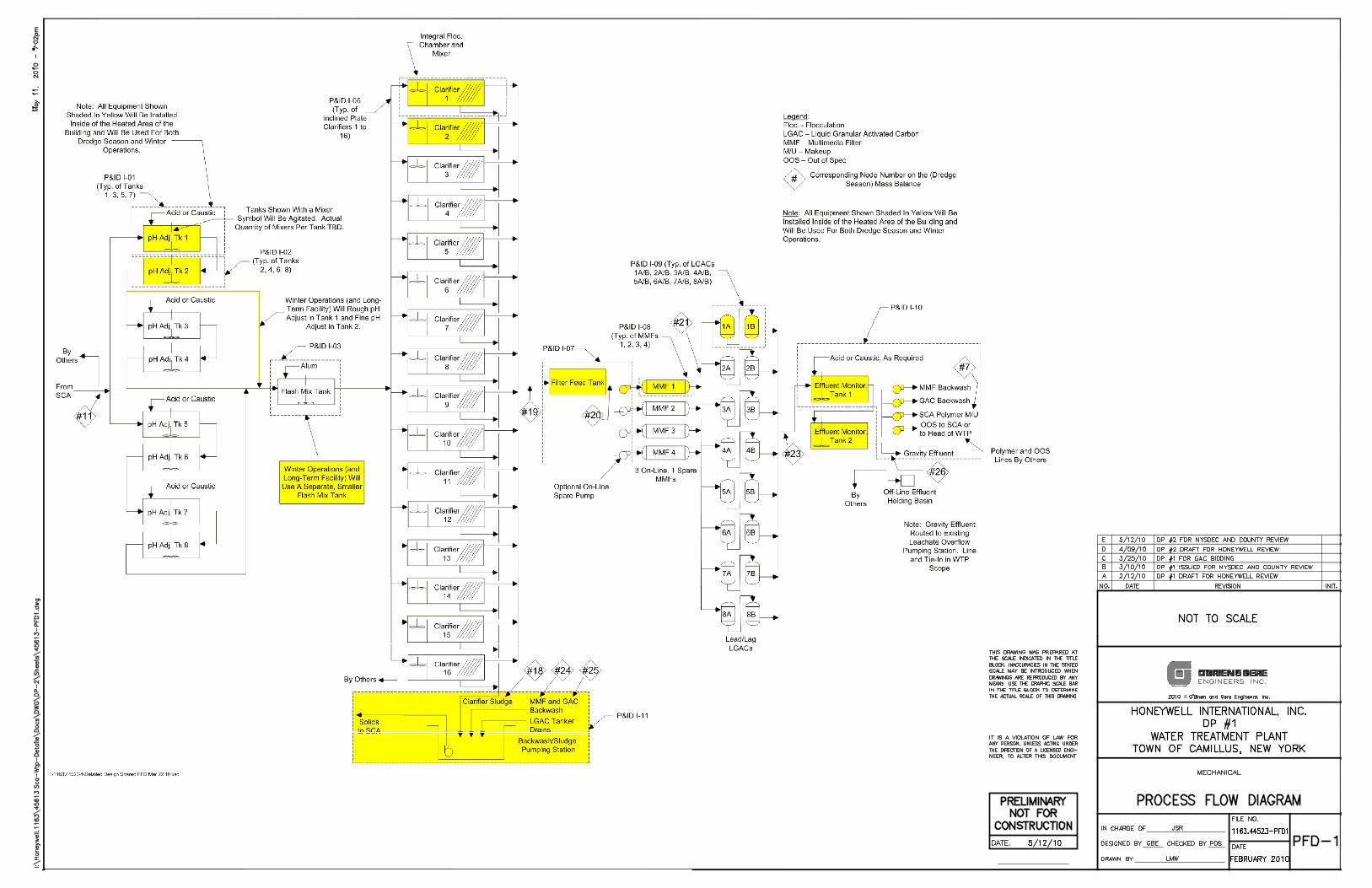
This memo documents the basis of design for each treatment process of the Sediment Consolidation Area (SCA) Water Treatment Plant (WTP).
The WTP will provide pretreatment of the SCA effluent prior to discharge to the Onondaga County Department of Water Environment Protection Metropolitan Wastewater Treatment Plant (Metro). Pretreatment of the SCA effluent will include removal of metals, solids, and volatile and semi-volatile organic compounds (VOCs and SVOCs). The pretreated water will receive enhanced ammonia removal at Metro. The WTP will include facilities for pH adjustment, chemical addition of a coagulant, clarification, multimedia filtration, carbon adsorption, and effluent monitoring. The WTP process flow diagram is attached as PFD-1, Rev. D, dated 4/9/10. The mass balances for the dredge season and winter operation are included as PFD-2, Rev. D, dated 4/9/10 and PFD-3, Rev. A, dated 4/9/10, respectively.
Procurement of the treatment system equipment may change some parameters but each unit process will need to substantially meet the requirements identified in the treatability testing.
SYSTEM CAPACITY – DREDGE SEASON
The WTP is designed to treat a maximum flow of 8.15 MGD (= 5663 gpm).
CHEMICAL BULK STORAGE
Chemical bulk storage is required for storage of chemicals used in the treatment process. Chemical dosage rates were established based on the treatability testing. Tank volumes were designed to provide approximately 5 days of chemical storage at the peak flow of 8.15 MGD.
The influent water will generally have a pH of approximately 9 to 12 s.u. As such, sulfuric acid will typically be used for pH reduction. Caustic (sodium hydroxide) feed is available for “over shoots” resulting from excessive acid feed and for the few months dredging occurs in the SMUs requiring pH adjustment to 10.5 s.u. for nickel precipitation. The caustic usage presented below is based on nickel precipitation and is a worst case scenario in terms of feed rate.
The estimated feed rates shown below correspond to dredge season operations and include the water portion of the chemical solution. Supporting calculations are included as Attachment A. The chemical usage shown on the mass balance reflects the neat chemical only and does not include the water portion. The neat chemical calculations are included as Attachment B.
20% Alum Design Criteria Used
Dosage 20 mg/L Estimated Feed Rate 665 gpd
Unit Details Number of Tanks 1 Volume 6,000 gal 9 days
50% Sodium Hydroxide
Design Criteria Used Dosage 160 mg/L Estimated Feed Rate 1,705 gpd
TO:
FROM:
RE:
FILE:
DATE:
File
LY Duff, GB Ebersbach
SCA WTP - Process Basis of Design
1163/45613
April 29, 2010, Rev. 1.0
cc: PD Schultz T Tong-Ngork NT Zacharek TR Komar
MEMORANDUM FILE APRIL 29, 2010 PAGE 2
I:\Honeywell.1163\45613.Sca-Wtp-Detaile\Docs\Memos\BOD Memos\Process Basis of Design rev 29-apr-10.doc
Rev. 4 – 4/9/10
Unit Details Number of Tanks 1 Volume 8,000 gal 4.7 days
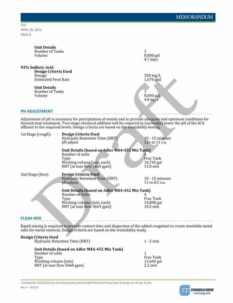
93% Sulfuric Acid
Design Criteria Used Dosage 350 mg/L Estimated Feed Rate 1,670 gpd Unit Details Number of Tanks 1 Volume 8,000 gal 4.8 days
PH ADJUSTMENT
Adjustment of pH is necessary for precipitation of metals and to provide adequate and optimum conditions for downstream treatment. Two-stage chemical addition will be required to (normally) lower the pH of the SCA effluent to the required levels. Design criteria are based on the treatability testing.
1st Stage (rough): Design Criteria Used Hydraulic Retention Time (HRT) 10 - 15 minutes pH adjust 12+ to 11 s.u.
Unit Details (based on Adler MX4-452 Mix Tank) Number of units 4 Type Frac Tank Working volume (min, each) 16,745 gal HRT (at max flow 5663 gpm) 11.8 min
2nd Stage (fine): Design Criteria Used
Hydraulic Retention Time (HRT) 10 - 15 minutes pH adjust 11 to 8.5 s.u. Unit Details (based on Adler MX4-452 Mix Tank) Number of Units 4 Type Frac Tank Working volume (min, each) 14,890 gal HRT (at max flow 5663 gpm) 10.5 min
FLASH MIX
Rapid mixing is required to provide contact time and dispersion of the added coagulant to create insoluble metal salts for metal removal. Design criteria are based on the treatability study.
Design Criteria Used Hydraulic Retention Time (HRT) 1 - 5 min Unit Details (based on Adler MX4-452 Mix Tank)
Number of units 1 Type Frac Tank Working volume (min) 12,660 gal HRT (at max flow 5668 gpm) 2.2 min

MEMORANDUM FILE APRIL 29, 2010 PAGE 3
I:\Honeywell.1163\45613.Sca-Wtp-Detaile\Docs\Memos\BOD Memos\Process Basis of Design rev 29-apr-10.doc
Rev. 4 – 4/9/10
FLOCCULATION
Flocculation is required to form insoluble floc particles to cluster together and form larger flocs to be settled and removed from the water in the clarifiers. Design criteria are based on the treatability testing.
Design Criteria Used Hydraulic Retention Time (HRT) 5 - 15 min Unit Details (based on Unipure 1000-G2 Drop-In)
Number of units 16 Type Integral to clarifier Volume (each) 5,000 gal HRT (at max flow 5668 gpm) 14 min
CLARIFIERS
The clarifiers will remove metals and solids contained in flocs created in the flash mix / floc chambers. Design criteria are based on the treatability study and literature values.
Design Criteria Used Surface Overflow Rate (SOR) 0.22 - 0.72 gpm/sf Influent TSS concentration 200 mg/l Effluent TSS concentration 10 mg/l Unit Details ((based on Unipure 1000-G2 Drop-In)
Number of units 16 Type Inclined Plate Normal Feed Rate (each) 355 gpm Settling Area (each) 1,300 ft2 SOR (at max flow 5668 gpm, with 16 units online) 0.27 gpm/sf
FILTER FEED TANK & PUMPS
Water from the inclined plate clarifiers will flow to a filter feed tank. From the filter feed tank, water will be pumped through the multimedia filters and granular activated carbon vessels.
Unit Details (based on Adler MX4-452 Mix Tank) Number of tanks 1 Type Frac Tank Working volume (min) 17,035 gal HRT (at max flow 4959 gpm) 3.4 min Number of pumps 3 Type Progressing cavity Capacity 1,700 gpm Drive Variable Frequency Drive
MULTIMEDIA FILTERS
Filtration is required to remove fine particles before the carbon adsorption processes. Design criteria are based on the treatability testing.
MEMORANDUM FILE APRIL 29, 2010 PAGE 4
I:\Honeywell.1163\45613.Sca-Wtp-Detaile\Docs\Memos\BOD Memos\Process Basis of Design rev 29-apr-10.doc
Rev. 4 – 4/9/10
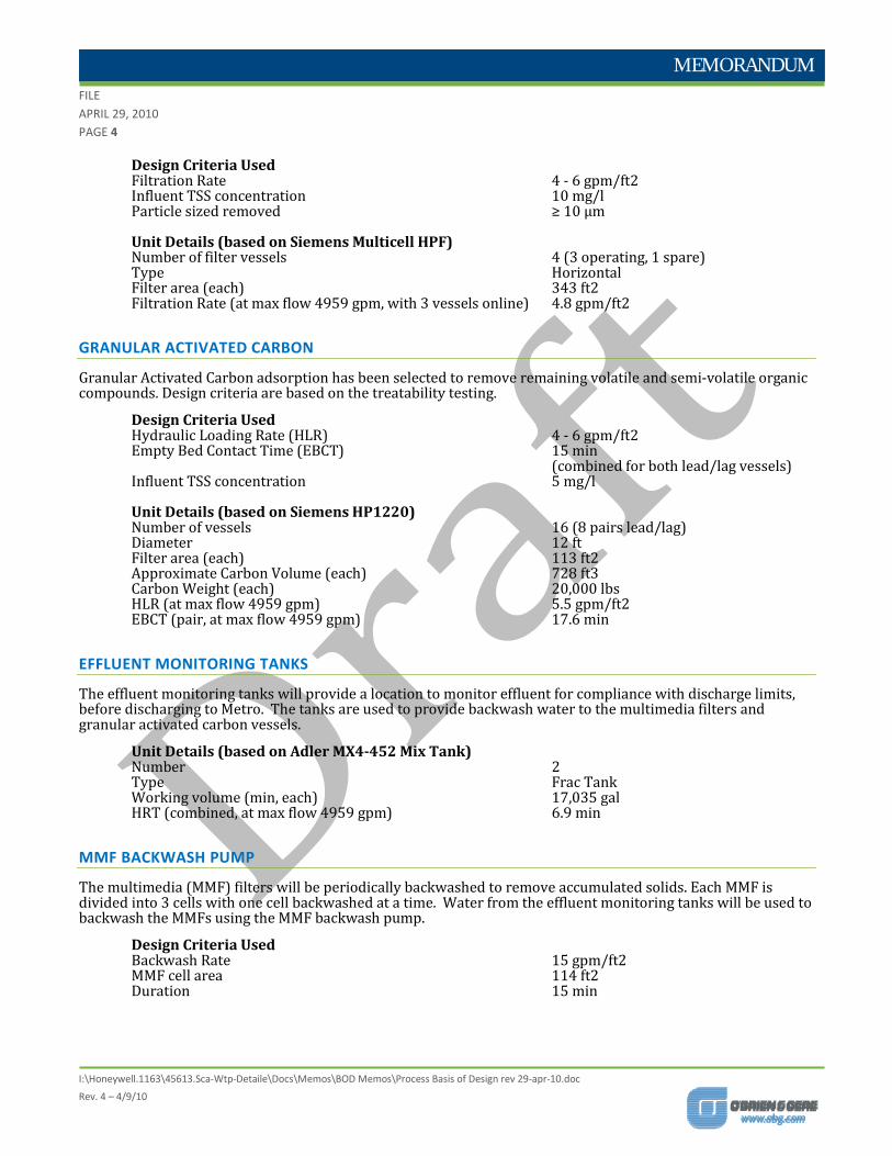
Design Criteria Used Filtration Rate 4 - 6 gpm/ft2 Influent TSS concentration 10 mg/l
Particle sized removed ≥ 10 μm
Unit Details (based on Siemens Multicell HPF) Number of filter vessels 4 (3 operating, 1 spare) Type Horizontal Filter area (each) 343 ft2 Filtration Rate (at max flow 4959 gpm, with 3 vessels online) 4.8 gpm/ft2
GRANULAR ACTIVATED CARBON
Granular Activated Carbon adsorption has been selected to remove remaining volatile and semi-volatile organic compounds. Design criteria are based on the treatability testing.
Design Criteria Used Hydraulic Loading Rate (HLR) 4 - 6 gpm/ft2 Empty Bed Contact Time (EBCT) 15 min (combined for both lead/lag vessels) Influent TSS concentration 5 mg/l
Unit Details (based on Siemens HP1220) Number of vessels 16 (8 pairs lead/lag) Diameter 12 ft Filter area (each) 113 ft2 Approximate Carbon Volume (each) 728 ft3 Carbon Weight (each) 20,000 lbs HLR (at max flow 4959 gpm) 5.5 gpm/ft2 EBCT (pair, at max flow 4959 gpm) 17.6 min
EFFLUENT MONITORING TANKS
The effluent monitoring tanks will provide a location to monitor effluent for compliance with discharge limits, before discharging to Metro. The tanks are used to provide backwash water to the multimedia filters and granular activated carbon vessels.
Unit Details (based on Adler MX4-452 Mix Tank) Number 2
Type Frac Tank Working volume (min, each) 17,035 gal HRT (combined, at max flow 4959 gpm) 6.9 min
MMF BACKWASH PUMP
The multimedia (MMF) filters will be periodically backwashed to remove accumulated solids. Each MMF is divided into 3 cells with one cell backwashed at a time. Water from the effluent monitoring tanks will be used to backwash the MMFs using the MMF backwash pump.
Design Criteria Used Backwash Rate 15 gpm/ft2 MMF cell area 114 ft2 Duration 15 min

MEMORANDUM FILE APRIL 29, 2010 PAGE 5
I:\Honeywell.1163\45613.Sca-Wtp-Detaile\Docs\Memos\BOD Memos\Process Basis of Design rev 29-apr-10.doc
Rev. 4 – 4/9/10
Unit Details Number of pumps 1 Type Centrifugal Capacity 1715 gpm Drive Variable Frequency Drive
GAC BACKWASH PUMP
The granular activated carbon (GAC) vessels will be periodically backwashed to remove accumulated solids. Water from the effluent monitoring tank will be used to backwash the GAC vessels using the GAC backwash pump. Since the GAC backwash pump and the MMF backwash pump are not expected to operate at the same time, the GAC backwash pump may be the same pump as the MMF backwash pump if the hydraulics for both meet the requirements.
Design Criteria Used Backwash Rate 12.5 gpm/ft2 GAC vessel area 113 ft2 Duration 15 min
Unit Details Number of pumps 1 Type Centrifugal Capacity 1415 gpm Drive Variable Frequency Drive
EFFLUENT RECYCLE PUMP
Off-spec effluent will be recycled back to the SCA (from the effluent monitoring tanks) using the effluent recycle pump(s).
Unit Details Number of pumps 1 Type Centrifugal Capacity 5000 gpm Drive Variable Frequency Drive
POLYMER MAKEDOWN WATER PUMP
Effluent from the effluent monitoring tanks will be used as polymer makedown water at the SCA for polymer pre-conditioning of the SCA sediment prior to dewatering in the geotextile tubes. Effluent will be pumped to the SCA using the polymer makedown water pump.
Unit Details Number of pumps 1 Type Centrifugal Capacity 175 gpm
BACKWASH/SLUDGE PUMPING STATION
Spent backwash water from the GACs and MMFs and sludge from the clarifiers will be discharged to the Backwash/Sludge Pumping Station. The pumping station will also be used to collect drainage from the spent carbon trailers prior to transport off-site. The collected waters and sludge will be returned to the SCA via pumps in the pumping station.
MEMORANDUM FILE APRIL 29, 2010 PAGE 6
I:\Honeywell.1163\45613.Sca-Wtp-Detaile\Docs\Memos\BOD Memos\Process Basis of Design rev 29-apr-10.doc
Rev. 4 – 4/9/10
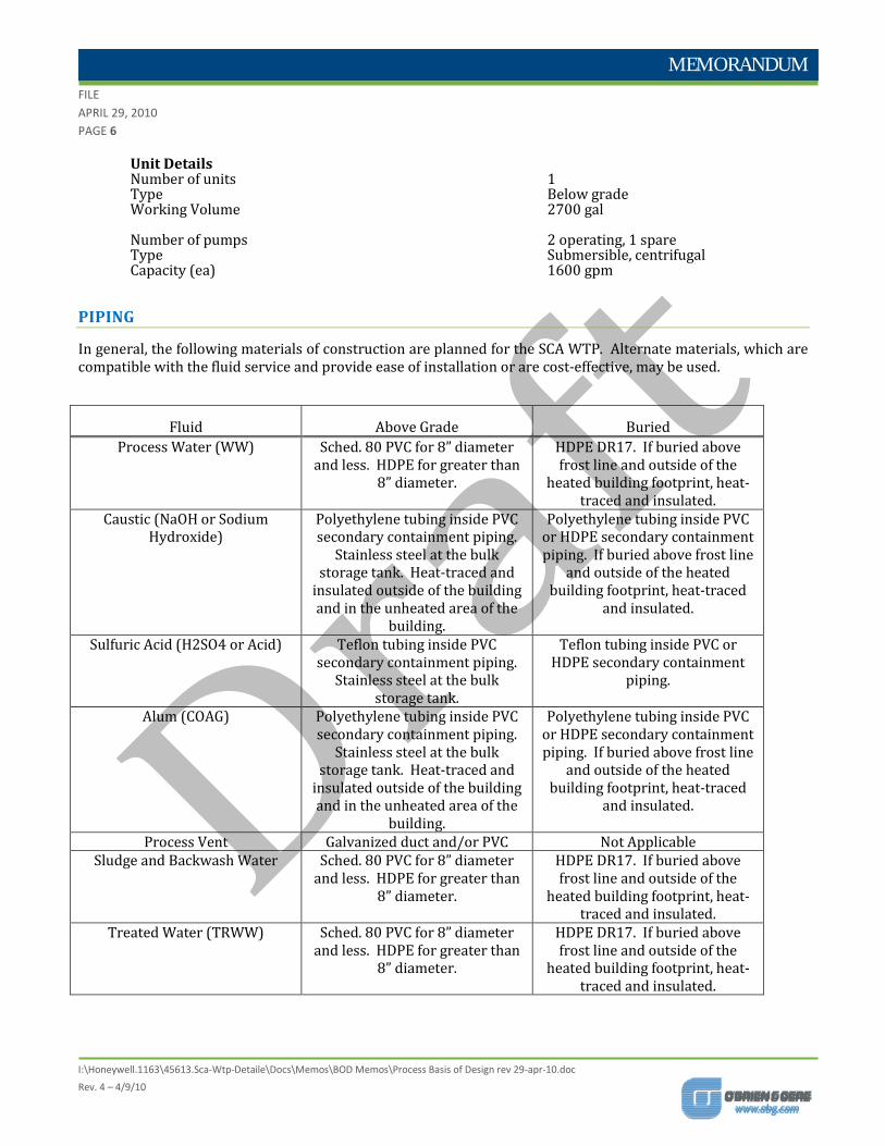
Unit Details Number of units 1 Type Below grade Working Volume 2700 gal Number of pumps 2 operating, 1 spare Type Submersible, centrifugal Capacity (ea) 1600 gpm
PIPING
In general, the following materials of construction are planned for the SCA WTP. Alternate materials, which are compatible with the fluid service and provide ease of installation or are cost-effective, may be used.
Fluid Above Grade Buried Process Water (WW) Sched. 80 PVC for 8” diameter
and less. HDPE for greater than 8” diameter.
HDPE DR17. If buried above frost line and outside of the
heated building footprint, heat-traced and insulated.
Caustic (NaOH or Sodium Hydroxide)
Polyethylene tubing inside PVC secondary containment piping.
Stainless steel at the bulk storage tank. Heat-traced and
insulated outside of the building and in the unheated area of the
building.
Polyethylene tubing inside PVC or HDPE secondary containment piping. If buried above frost line
and outside of the heated building footprint, heat-traced
and insulated.
Sulfuric Acid (H2SO4 or Acid) Teflon tubing inside PVC secondary containment piping.
Stainless steel at the bulk storage tank.
Teflon tubing inside PVC or HDPE secondary containment
piping.
Alum (COAG) Polyethylene tubing inside PVC secondary containment piping.
Stainless steel at the bulk storage tank. Heat-traced and
insulated outside of the building and in the unheated area of the
building.
Polyethylene tubing inside PVC or HDPE secondary containment piping. If buried above frost line
and outside of the heated building footprint, heat-traced
and insulated.
Process Vent Galvanized duct and/or PVC Not Applicable Sludge and Backwash Water Sched. 80 PVC for 8” diameter
and less. HDPE for greater than 8” diameter.
HDPE DR17. If buried above frost line and outside of the
heated building footprint, heat-traced and insulated.
Treated Water (TRWW) Sched. 80 PVC for 8” diameter and less. HDPE for greater than
8” diameter.
HDPE DR17. If buried above frost line and outside of the
heated building footprint, heat-traced and insulated.

MEMORANDUM FILE APRIL 29, 2010 PAGE 7
I:\Honeywell.1163\45613.Sca-Wtp-Detaile\Docs\Memos\BOD Memos\Process Basis of Design rev 29-apr-10.doc
Rev. 4 – 4/9/10
WINTER TREATMENT SYSTEM Influent flow during the winter is significantly reduced from the dredge season to 500 gpm or less consisting of seepage from the geotextile tubes and precipitation. With the exception of a separate flash mix tank, the winter treatment system will use a single train of equipment from the dredge season treatment system. Refer to dredge season equipment for basis of equipment selection.
SYSTEM CAPACITY
The winter treatment system is designed to treat a maximum flow of 500 gpm.
CHEMICAL BULK STORAGE
The estimated feed rates shown below include the water portion of the chemical solution. Supporting calculations are included as Attachment C. The chemical usage shown on the mass balance reflects the neat chemical only and does not include the water portion. The neat chemical calculations are included as Attachment D.
20% Alum Design Criteria Used
Dosage 20 mg/L Feed Rate 60 gpd Unit Details Number of Tanks 1 Volume 6,000 gal 100 days
50% Sodium Hydroxide
Design Criteria Used Dosage 160 mg/L Feed Rate 150 gpd Unit Details Number of Tanks 1 Volume 8,000 gal 50 days
93% Sulfuric Acid
Design Criteria Used Dosage 350 mg/L Feed Rate 150 gpd Unit Details Number of Tanks 1 Volume (each) 8,000 gal 50 days
PH ADJUSTMENT
1st Stage (rough): Design Criteria Used Hydraulic Retention Time (HRT) 10 - 15 minutes pH adjust 12+ to 11 s.u.

MEMORANDUM FILE APRIL 29, 2010 PAGE 8
I:\Honeywell.1163\45613.Sca-Wtp-Detaile\Docs\Memos\BOD Memos\Process Basis of Design rev 29-apr-10.doc
Rev. 4 – 4/9/10
Unit Details Number of units 1 Type Frac Tank Working volume (min) 16,745 gal HRT (at max flow 500 gpm) 33 min
2nd Stage (fine): Design Criteria Used
Hydraulic Retention Time (HRT) 10 - 15 minutes pH adjust 11 to 8.5 s.u. Unit Details Number of Units 1 Type Frac Tank Working volume (min) 14,890 gal HRT (at max flow 500 gpm) 30 min
FLASH MIX
A separate flash mix tank will be provided for the winter treatment system.
Design Criteria Used Hydraulic Retention Time (HRT) 1 - 5 min Unit Details (based on Design Tanks F084DT)
Number of units 1 Type Vertical, cylindrical Volume (min) 4,000 gal HRT (at max flow 500 gpm) 8 min
FLOCCULATION
Design Criteria Used Hydraulic Retention Time (HRT) 5 - 15 min Unit Details Number of units 2 Type Integral to clarifier Volume (each) 5,000 gal HRT (at max flow 500 gpm) 20 min
CLARIFIERS
Design Criteria Used Surface Overflow Rate (SOR) 0.22 - 0.72 gpm/sf Influent TSS concentration 150 mg/l Effluent TSS concentration 10 mg/l Unit Details Number of units 2 Type Inclined Plate Normal Feed Rate (each) 250 gpm Settling Area (each) 1,300 ft2 SOR (at max flow 500 gpm) 0.19 gpm/sf
MEMORANDUM FILE APRIL 29, 2010 PAGE 9
I:\Honeywell.1163\45613.Sca-Wtp-Detaile\Docs\Memos\BOD Memos\Process Basis of Design rev 29-apr-10.doc
Rev. 4 – 4/9/10
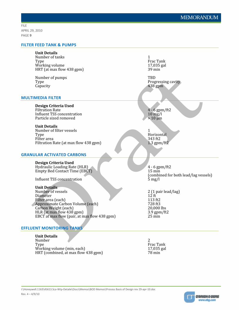
FILTER FEED TANK & PUMPS
Unit Details Number of tanks 1 Type Frac Tank Working volume 17,035 gal HRT (at max flow 438 gpm) 39 min Number of pumps TBD Type Progressing cavity Capacity 438 gpm
MULTIMEDIA FILTER
Design Criteria Used Filtration Rate 4 - 6 gpm/ft2 Influent TSS concentration 10 mg/l Particle sized removed > 10 μm Unit Details Number of filter vessels 1 Type Horizontal Filter area 343 ft2 Filtration Rate (at max flow 438 gpm) 1.3 gpm/ft2
GRANULAR ACTIVATED CARBONS
Design Criteria Used Hydraulic Loading Rate (HLR) 4 - 6 gpm/ft2 Empty Bed Contact Time (EBCT) 15 min (combined for both lead/lag vessels) Influent TSS concentration 5 mg/l
Unit Details Number of vessels 2 (1 pair lead/lag) Diameter 12 ft Filter area (each) 113 ft2 Approximate Carbon Volume (each) 728 ft3 Carbon Weight (each) 20,000 lbs HLR (at max flow 438 gpm) 3.9 gpm/ft2 EBCT at max flow (pair, at max flow 438 gpm) 25 min
EFFLUENT MONITORING TANKS
Unit Details Number 2 Type Frac Tank Working volume (min, each) 17,035 gal HRT (combined, at max flow 438 gpm) 78 min
©

©

©
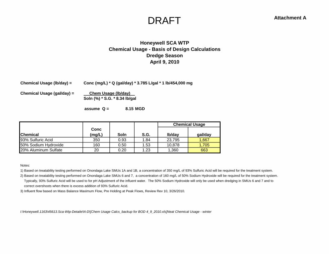
DRAFT Attachment A
Chemical Usage (lb/day) = Conc (mg/L) * Q (gal/day) * 3.785 L/gal * 1 lb/454,000 mg
Chemical Usage (gal/day) = Chem Usage (lb/day) Soln (%) * S.G. * 8.34 lb/gal
assume Q = 8.15 MGD
ChemicalConc
(mg/L) Soln S.G. lb/day gal/day93% Sulfuric Acid 350 0.93 1.84 23,795 1,66750% Sodium Hydroxide 160 0.50 1.53 10,878 1,70520% Aluminum Sulfate 20 0.20 1.23 1,360 663
Notes:1) Based on treatability testing performed on Onondaga Lake SMUs 1A and 1B, a concentration of 350 mg/L of 93% Sulfuric Acid will be required for the treatment system.2) Based on treatability testing performed on Onondaga Lake SMUs 6 and 7, a concentration of 160 mg/L of 50% Sodium Hydroxide will be required for the treatment system. Typically, 93% Sulfuric Acid will be used to for pH Adjustment of the influent water. The 50% Sodium Hydroxide will only be used when dredging in SMUs 6 and 7 and to correct overshoots when there is excess addition of 93% Sulfuric Acid.3) Influent flow based on Mass Balance Maximum Flow, Pre Holding at Peak Flows, Review Rev 10, 3/26/2010.
I:\Honeywell.1163\45613.Sca-Wtp-Detaile\N-D\[Chem Usage Calcs_backup for BOD 4_9_2010.xls]Neat Chemical Usage - winter
Chemical Usage
Honeywell SCA WTPChemical Usage - Basis of Design Calculations
April 9, 2010Dredge Season
DRAFT Attachment B
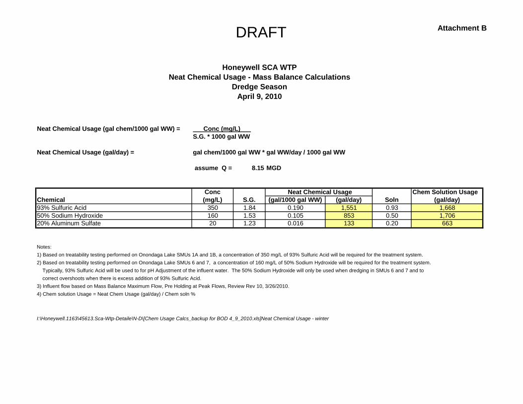
Neat Chemical Usage (gal chem/1000 gal WW) = Conc (mg/L) S.G. * 1000 gal WW
Neat Chemical Usage (gal/day) = gal chem/1000 gal WW * gal WW/day / 1000 gal WW
assume Q = 8.15 MGD
Conc Chem Solution UsageChemical (mg/L) S.G. (gal/1000 gal WW) (gal/day) Soln (gal/day)93% Sulfuric Acid 350 1.84 0.190 1,551 0.93 1,66850% Sodium Hydroxide 160 1.53 0.105 853 0.50 1,70620% Aluminum Sulfate 20 1.23 0.016 133 0.20 663
Notes:1) Based on treatability testing performed on Onondaga Lake SMUs 1A and 1B, a concentration of 350 mg/L of 93% Sulfuric Acid will be required for the treatment system.2) Based on treatability testing performed on Onondaga Lake SMUs 6 and 7, a concentration of 160 mg/L of 50% Sodium Hydroxide will be required for the treatment system. Typically, 93% Sulfuric Acid will be used to for pH Adjustment of the influent water. The 50% Sodium Hydroxide will only be used when dredging in SMUs 6 and 7 and to correct overshoots when there is excess addition of 93% Sulfuric Acid.3) Influent flow based on Mass Balance Maximum Flow, Pre Holding at Peak Flows, Review Rev 10, 3/26/2010.4) Chem solution Usage = Neat Chem Usage (gal/day) / Chem soln %
I:\Honeywell.1163\45613.Sca-Wtp-Detaile\N-D\[Chem Usage Calcs_backup for BOD 4_9_2010.xls]Neat Chemical Usage - winter
Neat Chemical Usage
Honeywell SCA WTPNeat Chemical Usage - Mass Balance Calculations
April 9, 2010Dredge Season

DRAFT Attachment C
Chemical Usage (lb/day) = Conc (mg/L) * Q (gal/day) * 3.785 L/gal * 1 lb/454,000 mg
Chemical Usage (gal/day) = Chem Usage (lb/day) Soln (%) * S.G. * 8.34 lb/gal
assume Q = 0.72 MGD
ChemicalConc
(mg/L) Soln S.G. lb/day gal/day93% Sulfuric Acid 350 0.93 1.84 2,101 14750% Sodium Hydroxide 160 0.50 1.53 960 15120% Aluminum Sulfate 20 0.20 1.23 120 59
Notes:1) Based on treatability testing performed on Onondaga Lake SMUs 1A and 1B, a concentration of 350 mg/L of 93% Sulfuric Acid will be required for the treatment system.2) Based on treatability testing performed on Onondaga Lake SMUs 6 and 7, a concentration of 160 mg/L of 50% Sodium Hydroxide will be required for the treatment system. Typically, 93% Sulfuric Acid will be used to for pH Adjustment of the influent water. The 50% Sodium Hydroxide will only be used when dredging in SMUs 6 and 7 and to correct overshoots when there is excess addition of 93% Sulfuric Acid.3) Influent flow based on Winter Conditions, Mass Balance Maximum Flow, Pre Holding at Peak Flows, Review Rev 10, 3/26/2010.
I:\Honeywell.1163\45613.Sca-Wtp-Detaile\N-D\[Chem Usage Calcs_backup for BOD 4_9_2010.xls]Neat Chemical Usage - winter
Honeywell SCA WTPChemical Usage - Basis of Design Calculations
April 9, 2010
Chemical Usage
Winter Operation
DRAFT Attachment D
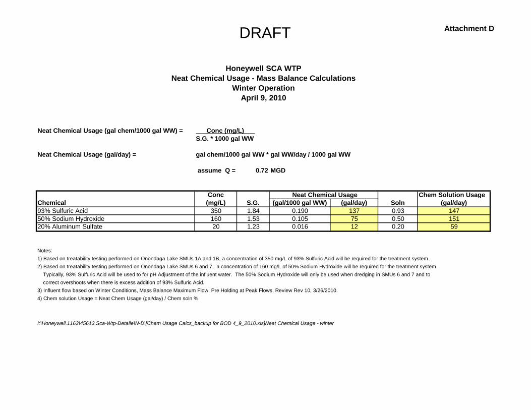
Neat Chemical Usage (gal chem/1000 gal WW) = Conc (mg/L) S.G. * 1000 gal WW
Neat Chemical Usage (gal/day) = gal chem/1000 gal WW * gal WW/day / 1000 gal WW
assume Q = 0.72 MGD
Conc Chem Solution UsageChemical (mg/L) S.G. (gal/1000 gal WW) (gal/day) Soln (gal/day)93% Sulfuric Acid 350 1.84 0.190 137 0.93 14750% Sodium Hydroxide 160 1.53 0.105 75 0.50 15120% Aluminum Sulfate 20 1.23 0.016 12 0.20 59
Notes:1) Based on treatability testing performed on Onondaga Lake SMUs 1A and 1B, a concentration of 350 mg/L of 93% Sulfuric Acid will be required for the treatment system.2) Based on treatability testing performed on Onondaga Lake SMUs 6 and 7, a concentration of 160 mg/L of 50% Sodium Hydroxide will be required for the treatment system. Typically, 93% Sulfuric Acid will be used to for pH Adjustment of the influent water. The 50% Sodium Hydroxide will only be used when dredging in SMUs 6 and 7 and to correct overshoots when there is excess addition of 93% Sulfuric Acid.3) Influent flow based on Winter Conditions, Mass Balance Maximum Flow, Pre Holding at Peak Flows, Review Rev 10, 3/26/2010.4) Chem solution Usage = Neat Chem Usage (gal/day) / Chem soln %
I:\Honeywell.1163\45613.Sca-Wtp-Detaile\N-D\[Chem Usage Calcs_backup for BOD 4_9_2010.xls]Neat Chemical Usage - winter
Honeywell SCA WTPNeat Chemical Usage - Mass Balance Calculations
April 9, 2010
Neat Chemical Usage
Winter Operation

Drawings

©


