

WD1 Open Front and Left (Timber Cavity)
Installation Guide
Operating Instructions
Warranty

Version: April 2019 2
WD1 Open Front & Left (Timber Cavity)
Installation Guide, Operating Instructions & Warranty
IMPORTANT!
This wood appliance must be installed to AS/NZS 2918:2001 by a qualified person and in accordance with these instructions. Failure to install the appliance correctly will void your warranty and may cause a fire. This appliance should not be modified under any circumstances. It is recommended that you have this appliance serviced annually by a qualified technician. Warranty repairs must be carried out by a ‘The Fire Dept.’ authorised technician. This appliance must ALWAYS terminate/flue outdoors. Young children, elderly or infirm should be supervised to ensure that they are careful with the appliance. Clothing and other flammable materials should never be placed near the appliance. Please note that parts (near the flame) of this appliance become extremely hot during operation and can result in serious injury and burns if touched. It is therefore recommended that a fireguard complying with BS 8423:2002 is used in the presence of young children, the elderly or infirm.
This installation guide must be read in conjunction with the technical specifications for this appliance. If an optional log ignitor is being used, it must be installed in accordance with the relevant log ignitor installation guide.
The WD1 (timber cavity) installation process consists of 12 steps
Page
Step 1: Ensure all components are correct and undamaged 3
Step 2: Pre-installation checklist 4
Step 3: Assemble steel support frame 5
Step 4: Fit steel support frame into cavity 6
Step 5: Fix side and rear AAC panels to steel support frame 7
Step 6: Fit gather 9
Step 7: Fit flue 10
Step 8: Fit front AAC panels to steel support frame 11
Step 9: Fit internal front and rear panels inside gather 12
Step 10: Install fire bricks 13
Step 11: Place grate into fire brick cavity 14
Step 12: Show owner how to operate appliance 15
Operating Instructions 16
Troubleshooting 16
Warranty 17
Information in this installation guide may be subject to change without notice.
Please ensure you have the current version before beginning installation.
If you have any queries, please contact ‘The Fire Dept.’ on 0800 888 550

Version: April 2019 3
Step 1: Unpack and ensure all components are correct and undamaged
Steel support frame components (flatpack).
Gather.
Internal front and rear panels.
AAC panels.
Grate.
Cavity closer panel.
Flue kit.
Fire bricks.
Log ignitor (optional).
WD1 Open Front & Left technical specification (to be read in conjunction with this installation guide)
Appropriate log Ignitor installation guide, if optional log ignitor is being used.

Version: April 2019 4
Step 2: Pre-installation checklist
Ensure cavity dimensions are correct – refer to technical specification.
Ensure hearth dimensions are correct – refer to technical specifications.
Plan flue path.
If optional log ignitor is to be installed, check how gas and electricity supplies run to log ignitor.
The starting point: Timber frame with concrete hearth.

Version: April 2019 5
Step 3: Assemble steel support frame
14 components, plus fasteners.
Steel support frame - view from above. Steel support frame components.
Assembled steel support frame. Note: Angle Lintel bar at front and side cover panel should not
be fitted yet.
Version: April 2019 6
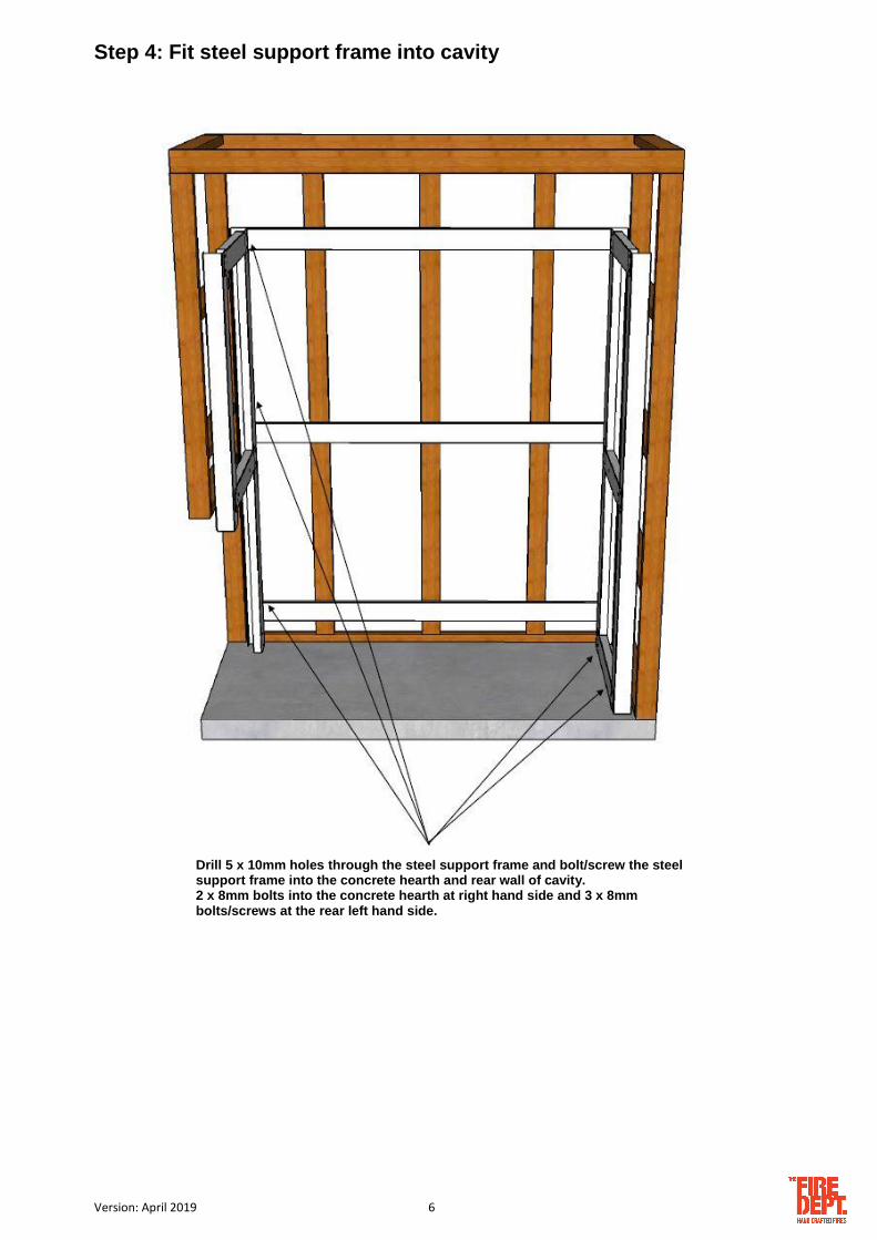
Step 4: Fit steel support frame into cavity
Drill 5 x 10mm holes through the steel support frame and bolt/screw the steel support frame into the concrete hearth and rear wall of cavity. 2 x 8mm bolts into the concrete hearth at right hand side and 3 x 8mm bolts/screws at the rear left hand side.

Version: April 2019 7
Step 5: Fix side and rear AAC panels to steel support frame
Uncut AAC panels and cement supplied.
Steel screws and wood screws supplied.
All joints must be cemented.
IMPORTANT! Refer to technical specification for latest version of cutting list.
1. Cut supplied AAC panels in accordance with technical specifications (example shown).

Version: April 2019 8
2. Fix sides horizontally to steel support frame. Countersink 4 x steel screws per panel
3. Fix first rear course vertically to steel support frame. Countersink 6 x steel screws per panel.
4. Fix second rear course horizontally to first vertical AACcourse. Countersink 6 x wood screws per panel.
Side and rear AAC panels complete.

Version: April 2019 9
Step 6: Fit gather
7 components, plus fasteners.
1. Remove outer brackets, side cover panel
and internal front and rear panels. 2. Bolt outer brackets through AAC panels
Into steel support frame – 2 x bolts each side.
3. With a minimum of two people, fit gather onto outer brackets. 2 x bolts each side (into slots which allow adjustment).
Gather Outer bracket
(x 2)
Inner
Bracket (x 2)
4. Bolt the left side cover panel up into position, covering the undersides of both inner and outer
brackets.

Version: April 2019 10
Step 7: Fit flue
1. Fit angle lintel bar then run the first section of flue and flue reducer
onto gather.
2. Run the first section of inner casing and casing reducer onto gather. Ensure 25mm
gap between casing reducer and gather.
3. Fix the closer panel into position on top of the steel support frame. Then run the first section of the outer casing onto the closer panel.
4. Complete the rest of the flue installation.
Angle lintel bar
Closer panel

Version: April 2019 11
Step 8: Fit front AAC panels to steel support frame
Steel screws and wood screws supplied.
All joints must be cemented.
1. Fix front vertical AAC panel onto previously fitted AAC side panel. 2 x wood screws.
2. Fix front horizontal AAC panels onto steel support frame. 4 x steel screws per panel.
Front AAC panels complete.
Version: April 2019 12
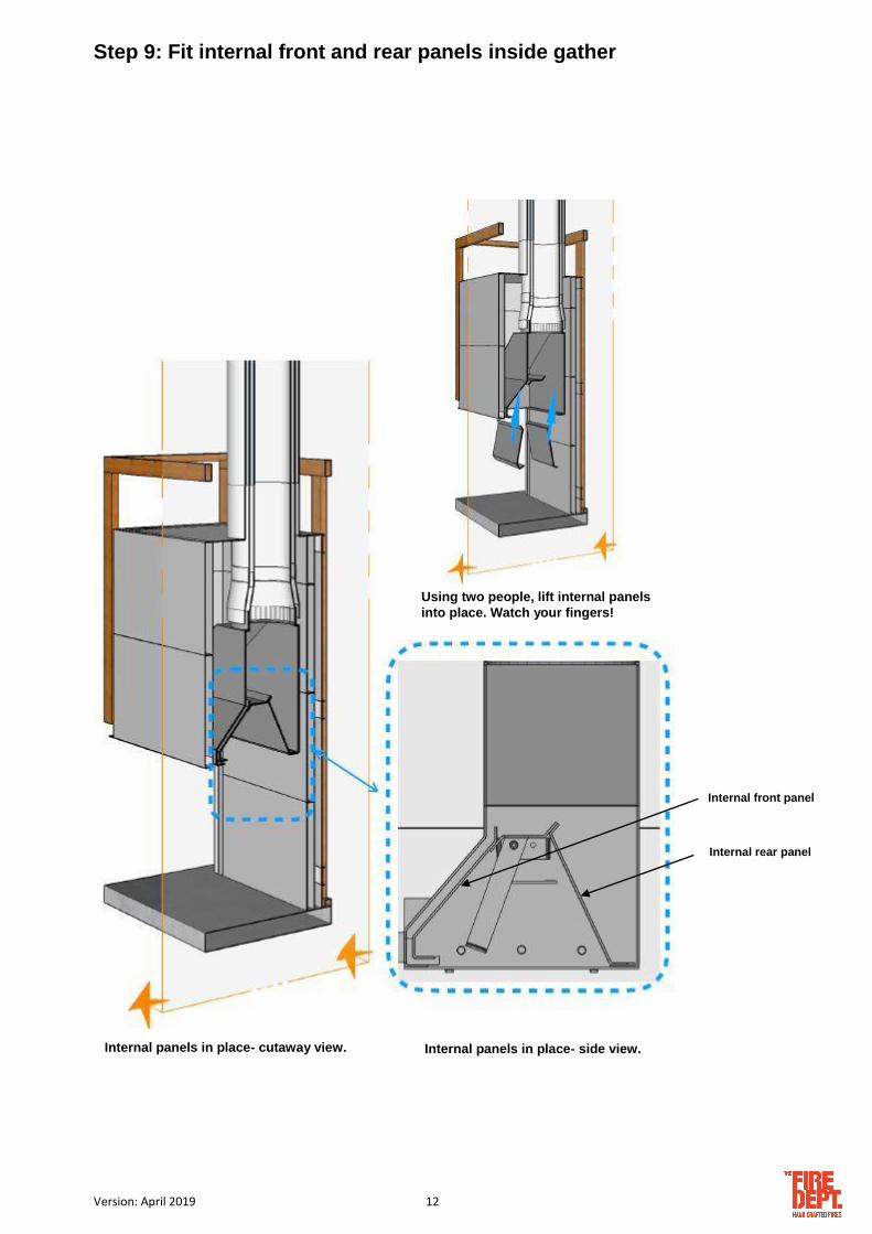
Step 9: Fit internal front and rear panels inside gather
Using two people, lift internal panels
into place. Watch your fingers!
Internal panels in place- cutaway view.
Internal panels in place- side view.
Internal front panel
Internal rear panel

Version: April 2019 13
Step 10: Install fire bricks
Fire bricks complete.
IMPORTANT: To avoid smoke entering the cavity, ensure the fire bricks are flush with the gather internal back panel and side. Fill gap between fire-bricks and underside of gather with refractory cement.

Version: April 2019 14
Step 11: Place grate into fire brick cavity
Place the grate 150mm in from the fire brick side wall.
Appliance is now ready for customer-specified outer finishes.

Version: April 2019 15
Step 12: Show owner how to operate appliance Following the Operating Instructions on the next page, show the owner how to operate the flue damper,
and if fitted, the log ignitor.
If the owner is not available, leave this manual by the appliance.

Version: April 2019 16
OPERATING INSTRUCTIONS
The WD1 has an integrated flue damper which has two positions – open and closed.
The flue damper MUST be in the open position when the fire is being used. To set the flue damper to the open position, simply push it to the rear of the fire.
If the fire is not being used for an extended period (for example, over summer), the flue damper can be pulled forward to the closed position, which reduces external noises and drafts.
Ongoing maintenance. It is recommended that the flue be swept every year (some insurance
companies require this), or more often if required. Fire bricks will deteriorate over time and must be regularly checked for cracking and movement. Repair or replace as required.
……………………………………
TROUBLESHOOTING
Problem
Probable Cause
Action
Smoke is entering room
1. Poor quality or damp wood 2. Flue damper is closed 3. Draft flowing into or across fire 4. Flue terminates at poor position
outside (eg. windy part of roof) 5. A nearby extractor fan is sucking
smoke from the fire
1. Change wood 2. Open flue damper 3. Remove source of draft 4. Reposition flue termination 5. Switch off or reposition extractor fan
Flue damper doesn’t stay in open position
Flue dumper bolts have loosened
Tighten flue dumper bolts and locknuts – one of each side
Flue Damper

Version: April 2019 17
PRODUCT WARRANTY
IMPORTANT: Evidence of original purchase is required for warranty service.
WARRANTOR: ‘The Fire Dept.’ (Landscape Elements Ltd)
85 Newton Road Mount Maunganui PO Box 10275, Bayfair, Mount Maunganui
ELEMENT OF WARRANTY
‘The Fire Dept.’ warrants to the original retail owner for the duration of this warranty, it’s fireboxes, gas burner tray, lighters, (herein after referred to as the Product) to be free from defects in materials and craftsmanship with only the limitations or exclusions set out below.
WARRANTY
This warranty will be deemed invalid if the Product is;
(A) Installed by someone other than an authorised Fire Dept agent.
(B) Not operated appropriately or “over-fired” in a manner resulting in the firebox operating excessively hot.
(C) Not serviced and maintained by a certified gas fitter every 12 months.
(D) Damaged by accident, neglect or misuse,
(E) Repaired by someone other than an authorised Fire Dept repair agent for a defect or malfunction covered by this warranty.
(F) Modified, altered or used as part of any conversion kits, subassemblies, or any configurations not sold by ‘The Fire Dept.’.
(G) The product contains fire bricks and has not been subjected to the recommended first start-up and run-in procedure.
(H) Used in conjunction with any equipment or parts or as part of a system not manufactured or supplied by ‘The Fire Dept.’.
(I) External powder-coating within 200m of the high tide mark and not lightly washed with warm soapy water every three months.
Indoor appliances (Gas & Wood)
‘The Fire Dept.’. warrants the mild steel firebox, galvanised steel outer skin and RHS Duragal steel support frame against defective materials and workmanship which would render it unfit for normal domestic use, from the date of purchase by the original consumer, for a period of 5 (five) years. Beyond normal heat-induced staining, tarnishing and mild warping , if a firebox, outer skin or support frame defect occurs, contact ‘The Fire Dept.’ and the defect will be repaired or replaced at our discretion with all costs covered.
‘The Fire Dept.’ warrants the SIT Pack (Gas regulator and controller) against defective materials and workmanship which would render it unfit for normal domestic use, from the date of purchase by the original consumer, for a period of 2 (two) years.
Components including fire medium, fans, tiles, glass and glass trim are warranted for a period of 2 (two) years from the date of original purchase, against defective materials and workmanship.
Outdoor appliances (Gas & Wood)
‘The Fire Dept.’ warrants the Mild Steel firebox, galvanised steel outer skin and RHS Duragal Steel support frame against defective materials and workmanship which would render it unfit for normal domestic use, from the date of purchase by the original consumer, for a period of 2 (two) years. Beyond normal heat-induced staining, tarnishing and mild warping, If a firebox, outer skin or support frame defect occurs, contact ‘The Fire Dept.’ and the defect will be repaired or replaced at our discretion with all costs covered.
‘The Fire Dept.’ warrants the SIT Pack (Gas regulator and controller) against defective materials and workmanship which would render it unfit for normal domestic use, from the date of purchase by the original consumer, for a period of 2 (two) years.
Components including fire medium, fans, tiles, glass and glass trim are warranted for a period of 2 (two) years from the date of original purchase for domestic use, against defective materials and workmanship.
STATEMENT OF REMEDY
In the event that the Product does not conform to this warranty at any time while this warranty is in effect, the Warrantor, at its discretion, will repair the defect or replace the part and return it to you without charge for parts or service. This warranty does not provide for reimbursement or payment of incidental or consequential damages.
This warranty does not in any way affect your rights under the Consumers Guarantee Act (New Zealand).


