
Products Solutions ServicesBA00144R/09/EN/14.1471267180
Firmware version:03.07.xx
Operating InstructionsRMC 621Energy Manager

RMC621
2 Endress+Hauser
Brief overview
For quick and easy commissioning:Safety instructions → ä 8
Installation → ä 11
Wiring → ä 13
Display and operating elements → ä 23
Commissioning → ä 30
Quick start via the navigator to device configuration for standard operation.Device configuration - explanation and use of all configurable device functions with the associated value ranges and settings.Application example - configuration of the device.
Applications for the Energy Manager
The device compensates flow measurements of gas, liquid and steam based on the following methods of calculation:
Gases:• Improved ideal gas law: flow correction by taking the temperature, pressure and average compressibility into
account.• Real gas equations (SRK, RK) and possibility of entering tables for calculating the compressibility and density
of technical gases or density input.• Natural gas using international calculation standard NX19, SGERG88 and AGA8 (optional).
Liquids:• Determining density via algorithms and tables• Thermal capacity as constant or table (heating value as constant)• Mineral oil density as per calculation standards ASTM 1250, API 2540, OIML R63 (optional)
Steam/water:• International calculation standard IAPWS IF-97 (ASME tables)
RMC621
Endress+Hauser 3
Brief operating instructions
The information contained in these Operating Instructions serves as a guide to help you commission your device easily, i.e. the most important settings are listed here but special functions (e.g. Tables, Corrections etc.) are not.Configuring a measurementExample: gas normal volume, sensors: (Prowirl 77, Cerabar T, TR10)
1. Connect device to the power source (terminal L/L+, 220 V)
2. Press any key → Menu → Setup
3. Basic set-upDate-Time (set the date and time) → ZSystem eng. units (select metric or American) → Z
4. Inputs → Flow inputs (flow 1)DPT: volumetricSignal: PFMTerminals: select A10 and connect Prowirl to terminal A10(-)/82(+) (as passive signal)Configure the K-factor (as per Prowirl nameplate) → Z
5. Pressure inputs (pressure 1)Signal: e.g. 4 to 20 mATerminals: select A110 and connect pressure transmitter to terminal A110(-)/83(+)-Type: select absolute pressure measurement or relative pressure measurement Configure the start and end value of the pressure transmitter → Z
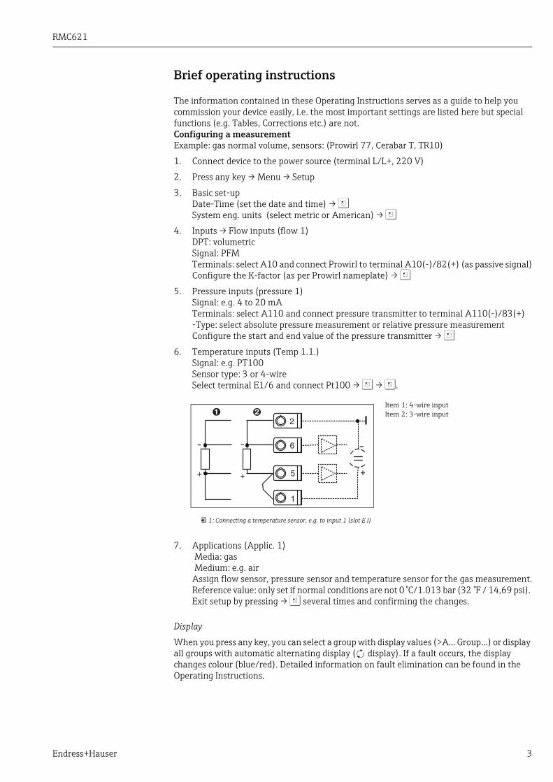
6. Temperature inputs (Temp 1.1.)Signal: e.g. PT100Sensor type: 3 or 4-wireSelect terminal E1/6 and connect Pt100 → Z → Z.
7. Applications (Applic. 1) Media: gas Medium: e.g. airAssign flow sensor, pressure sensor and temperature sensor for the gas measurement.Reference value: only set if normal conditions are not 0 °C/1.013 bar (32 °F / 14,69 psi). Exit setup by pressing → Z several times and confirming the changes.
Display
When you press any key, you can select a group with display values (>A... Group...) or display all groups with automatic alternating display ( display). If a fault occurs, the display changes colour (blue/red). Detailed information on fault elimination can be found in the Operating Instructions.
1: Connecting a temperature sensor, e.g. to input 1 (slot E I)
Item 1: 4-wire inputItem 2: 3-wire input
RMC621
4 Endress+Hauser
Application settingsProgramming data at a glance for configuring the measurement
Gas norm volume/gas mass/gas heat val
1. Gases already stored in the device
(Air, O2, CO2, N2, CH4, Ar, H2, acetylene, ammonia, natural gas) Press any key → Menu → Setup.
2. Gases not already stored in the device
Press any key → Menu → Setup.
Make other settings for the inputs and application as explained in Point 1.
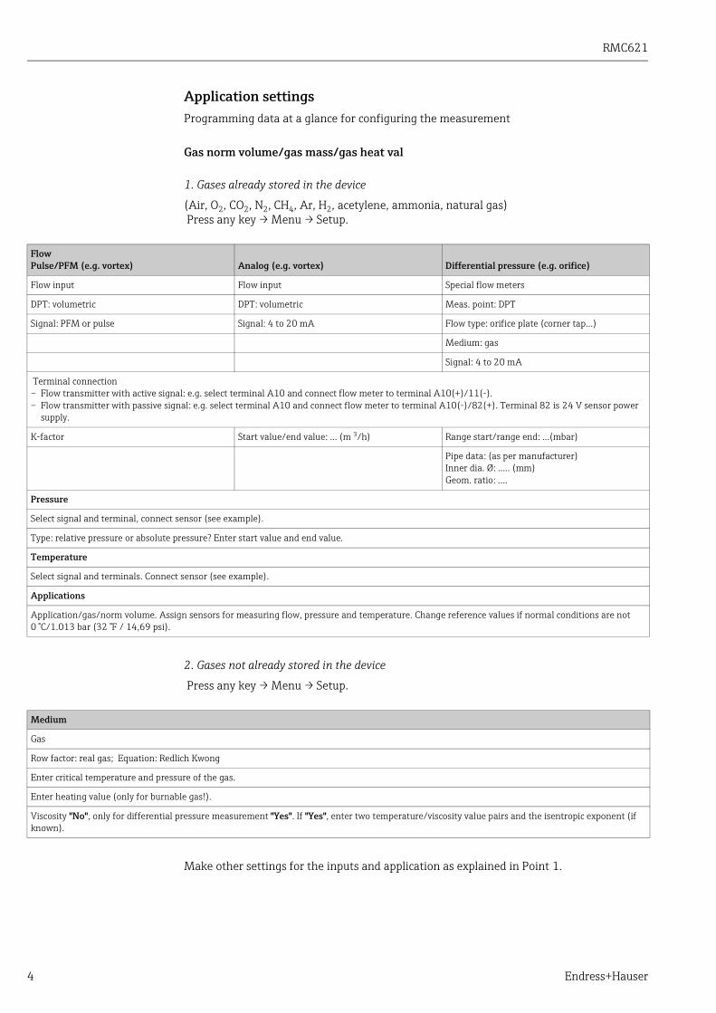
FlowPulse/PFM (e.g. vortex) Analog (e.g. vortex) Differential pressure (e.g. orifice)
Flow input Flow input Special flow meters
DPT: volumetric DPT: volumetric Meas. point: DPT
Signal: PFM or pulse Signal: 4 to 20 mA Flow type: orifice plate (corner tap...)
Medium: gas
Signal: 4 to 20 mA
Terminal connection– Flow transmitter with active signal: e.g. select terminal A10 and connect flow meter to terminal A10(+)/11(-).– Flow transmitter with passive signal: e.g. select terminal A10 and connect flow meter to terminal A10(-)/82(+). Terminal 82 is 24 V sensor power
supply.
K-factor Start value/end value: ... (m 3/h) Range start/range end: ...(mbar)
Pipe data: (as per manufacturer)Inner dia. Ø: ..... (mm)Geom. ratio: ....
Pressure
Select signal and terminal, connect sensor (see example).
Type: relative pressure or absolute pressure? Enter start value and end value.
Temperature
Select signal and terminals. Connect sensor (see example).
Applications
Application/gas/norm volume. Assign sensors for measuring flow, pressure and temperature. Change reference values if normal conditions are not 0 °C/1.013 bar (32 °F / 14,69 psi).
Medium
Gas
Row factor: real gas; Equation: Redlich Kwong
Enter critical temperature and pressure of the gas.
Enter heating value (only for burnable gas!).
Viscosity "No", only for differential pressure measurement "Yes". If "Yes", enter two temperature/viscosity value pairs and the isentropic exponent (if known).

RMC621
Endress+Hauser 5
Liquid heat difference, heat quantity, heating value
Input variables: flow, temperature, density (optional)
1. Liquids already stored in the device (propane, butane)
2. Liquids not already stored in the device
Any heat transfer fluids or combustible fluids.Input variables: flow, temperature 1, (temperature 2), density (optional)
FlowPulse/PFM (e.g. vortex) Analog (e.g. EFM) Differential pressure (e.g. orifice)
Flow input Flow input Special flow meters
DPT: volumetric DPT: volumetric Meas. point: DPT
Signal: PFM or pulse Signal: 4 to 20 mA Flow type: orifice plate (corner tap...)
Medium: liquid
Signal: 4 to 20 mA
Terminal connection– Flow transmitter with active signal: e.g. select terminal A10 and connect flow meter to terminal A10(+)/11(-).– Flow transmitter with passive signal: e.g. select terminal A10 and connect flow meter to terminal A10(-)/82(+). Terminal 82 is 24 V sensor power
supply.
K-factor Start value/end value: ... (m3/h) Range start/range end: ...(mbar)
Pipe data: (as per manufacturer), inner dia. Ø:...(mm)Geom. ratio: ....
Temperature
Select signal, terminals, connect sensor(s) (see example). Heat difference measurements require 2 temperature sensors.
Applications
Application(1); media: liquid; meas. media: e.g. butane
Liquid appl.: heating val
Assign sensors for measuring flow and temperature.
Spec. fluid
Liquid
Density calc.: linear
Enter density at a certain temperature (ref temperature, ref density)
Expansion: enter liquid expansion coefficient (if known)
Enter sp. heat cap. or heating value (for combustible fluid)
Viscosity "No", "Yes" for differential pressure measurement, then enter two temperature/viscosity value pairs and the isentropic exponent (if known).
Flow and temperature
Make other settings for the inputs as explained in Point 1.
Applications
Application(1); media: liquid; meas. media: xxx
Liquid appl.: e.g. heat difference
Op. mode: (e.g. heating)
Assign sensors for measuring flow and temperature.
Inst. point: assign warm/cold T
For the bidirectional operating mode, or if measuring density with a sensor, configure additional terminals if necessary.

RMC621
6 Endress+Hauser
Water applications
Input variables: flow, temperature 1, (temperature 2)
Steam applications
Input variables: flow, pressure, temperature 1, (temperature 2)
FlowPulse/PFM (e.g. vortex) Analog (e.g. vortex) Differential pressure (e.g. orifice)
Flow input Flow input Special flow meters
DPT: volumetric DPT: volumetric Diff. press./orifice.../water
Terminal connection– Flow transmitter with active signal: e.g. select terminal A10 and connect flow meter to terminal A10(+)/11(-).– Flow transmitter with passive signal: e.g. select terminal A10 and connect flow meter to terminal A10(-)/82(+). Terminal 82 is 24 V sensor power
supply.
K-factor Start value/end value (m3/h) Start value/end value (mbar)
Temperature
Select signal and connect sensor(s) (see example). Heat difference measurements require 2 temperature sensors.
Applications
Application(1); media: water/steam
Application: e.g. water heat diff.
Op. mode: (e.g. heating)
Assign sensors for measuring flow and temperature.
Inst. point: assign warm/cold T
If the application is heat quantity, only one temperature is available. For the bidirectional operating mode, an additional terminal for direction signal may be necessary.
FlowPulse/PFM (e.g. vortex) Analog (e.g. vortex) Differential pressure (e.g. orifice)
Flow input Flow input Special flow meters
DPT: volumetric DPT: volumetric Diff. press./orifice.../steam
Terminal connection– Flow transmitter with active signal: e.g. select terminal A10 and connect flow meter to terminal A10(+)/11(-).– Flow transmitter with passive signal: e.g. select terminal A10 and connect flow meter to terminal A10(-)/82(+). Terminal 82 is 24 V sensor power
supply.
K-factor Start value/end value (m3/h) Start value/end value (mbar)
Pressure
Select signal and terminal and connect sensor (see example).
Type: relative pressure or absolute pressure? Enter start value and end value.
Temperature
Select signal and connect sensor(s) (see example). Steam difference measurements require 2 temperature sensors.
Applications
Application(1); media: water/steam
Application: e.g. steam mass/heat
Steam type: e.g. superheated steam
Assign sensors for measuring flow, pressure and temperature.
RMC621
Endress+Hauser 7
Table of contents
1 Safety instructions . . . . . . . . . . . . . . . . . . 81.1 Designated use . . . . . . . . . . . . . . . . . . . . . . . . . . . . . 81.2 Installation, commissioning and operation . . . . . . 81.3 Operational safety . . . . . . . . . . . . . . . . . . . . . . . . . . . 81.4 Return . . . . . . . . . . . . . . . . . . . . . . . . . . . . . . . . . . . . . 81.5 Notes on safety conventions and icons . . . . . . . . . 9
2 Identification . . . . . . . . . . . . . . . . . . . . . 102.1 Device designation . . . . . . . . . . . . . . . . . . . . . . . . 102.2 Scope of delivery . . . . . . . . . . . . . . . . . . . . . . . . . . 102.3 Certificates and approvals . . . . . . . . . . . . . . . . . . 10
3 Installation . . . . . . . . . . . . . . . . . . . . . . . 113.1 Installation conditions . . . . . . . . . . . . . . . . . . . . . 113.2 Installation instructions . . . . . . . . . . . . . . . . . . . . 113.3 Post-installation check . . . . . . . . . . . . . . . . . . . . . 12
4 Wiring . . . . . . . . . . . . . . . . . . . . . . . . . . . 134.1 Quick wiring guide . . . . . . . . . . . . . . . . . . . . . . . . 134.2 Connecting the measuring unit . . . . . . . . . . . . 144.3 Post-connection check . . . . . . . . . . . . . . . . . . . . . 22
5 Operation. . . . . . . . . . . . . . . . . . . . . . . . . 235.1 Display and operating elements . . . . . . . . . . . . . 235.2 Local operation . . . . . . . . . . . . . . . . . . . . . . . . . . . 245.3 Error message display . . . . . . . . . . . . . . . . . . . . . . 265.4 Communication . . . . . . . . . . . . . . . . . . . . . . . . . . . 28
6 Commissioning. . . . . . . . . . . . . . . . . . . . 306.1 Function check . . . . . . . . . . . . . . . . . . . . . . . . . . . 306.2 Switching on the measuring device . . . . . . . . . 306.3 Device configuration . . . . . . . . . . . . . . . . . . . . . . . 316.4 User-specific applications . . . . . . . . . . . . . . . . . . 55
7 Maintenance. . . . . . . . . . . . . . . . . . . . . . 58
8 Accessories . . . . . . . . . . . . . . . . . . . . . . . 58
9 Trouble-shooting . . . . . . . . . . . . . . . . . . 599.1 Trouble-shooting instructions . . . . . . . . . . . . . . . 599.2 System error messages . . . . . . . . . . . . . . . . . . . . . 599.3 Process error messages . . . . . . . . . . . . . . . . . . . . 609.4 Spare parts . . . . . . . . . . . . . . . . . . . . . . . . . . . . . . . 639.5 Return . . . . . . . . . . . . . . . . . . . . . . . . . . . . . . . . . . . 659.6 Disposal . . . . . . . . . . . . . . . . . . . . . . . . . . . . . . . . . 65
10 Technical data . . . . . . . . . . . . . . . . . . . . 66
11 Appendix . . . . . . . . . . . . . . . . . . . . . . . . . 7511.1 Definition of important system units . . . . . . . . . 75
11.2 Flow measurement configuration . . . . . . . . . . . . 7611.3 Application sheets . . . . . . . . . . . . . . . . . . . . . . . . . 8111.4 Overview function matrix . . . . . . . . . . . . . . . . . . . 95
Index . . . . . . . . . . . . . . . . . . . . . . . . . . . . 98
Safety instructions RMC621
8 Endress+Hauser
1 Safety instructionsSafe operation of the Flow and Energy Manager is only guaranteed if these Operating Instructions have been read and the safety instructions have been observed.
1.1 Designated useThe Flow and Energy Manager is an instrument for measuring the flow, mass and energy flow of gases, liquids, steam and water. The multi-channel concept allows simultaneous measurement of fluid and applications, e.g. calculation of a gas norm volume flow and/or energy balancing in a heating or cooling system.A wide range of different types of flow transmitters, temperature sensors and pressure sensors can be connected to the device.The Flow and Energy Manager offers a wide variety of calculation methods for determining the desired process values for the industrial requirements, real gas equations, editable tables for density, thermal capacity, compressibility, international calculation standards for natural gas (e.g. SGERG88) or steam (IAPWS IF-97), flow-differential pressure method (ISO5167) etc.
– The device is seen as accessory equipment and may not be installed in hazardous areas.– The manufacturer does not accept liability for damage caused by improper or non-
designated use. The device may not be converted or modified in any way.– The device is designed for use in industrial environments and may only be operated in an
installed state.
1.2 Installation, commissioning and operationThis device has been safely built with state-of-the-art technology and meets the applicable requirements and EU Directives. The device can be a source of application-related danger if used improperly or other than intended.Installation, wiring, commissioning and maintenance of the device must only be carried out by trained technical personnel. Technical personnel must have read and understood these Operating Instructions and must adhere to them. The information in the electrical wiring diagrams (see Section 4 ’Wiring’) must be observed closely.
1.3 Operational safetyTechnical improvementThe manufacturer reserves the right to adapt technical details to the most up-to-date technical developments without any special announcement. Contact your local sales centre for information about the current state of and possible extensions to the Operating Instructions.
1.4 ReturnFor a return, e.g. in case of repair, the device must be sent in protective packaging. The original packaging offers the best protection. Repairs must only be carried out by your supplier's service organisation.
When sending for repair, please enclose a note with a description of the error and the application.

RMC621 Safety instructions
Endress+Hauser 9
1.5 Notes on safety conventions and iconsThe safety instructions in these Operating Instructions are labelled with the following safety icons and symbols:
Symbol Bedeutung
A0011189-DE
DANGER!This symbol alerts you to a dangerous situation. Failure to avoid this situation will result in serious or fatal injury.
A0011190-DE
WARNING! This symbol alerts you to a dangerous situation. Failure to avoid this situation can result in serious or fatal injury.
A0011191-DE
CAUTION! This symbol alerts you to a dangerous situation. Failure to avoid this situation can result in minor or medium injury.
A0011192-DE
NOTICEThis symbol contains information on procedures and other facts which do not result in personal injury.
TIPIndicates additional information.
Identification RMC621
10 Endress+Hauser
2 Identification
2.1 Device designation
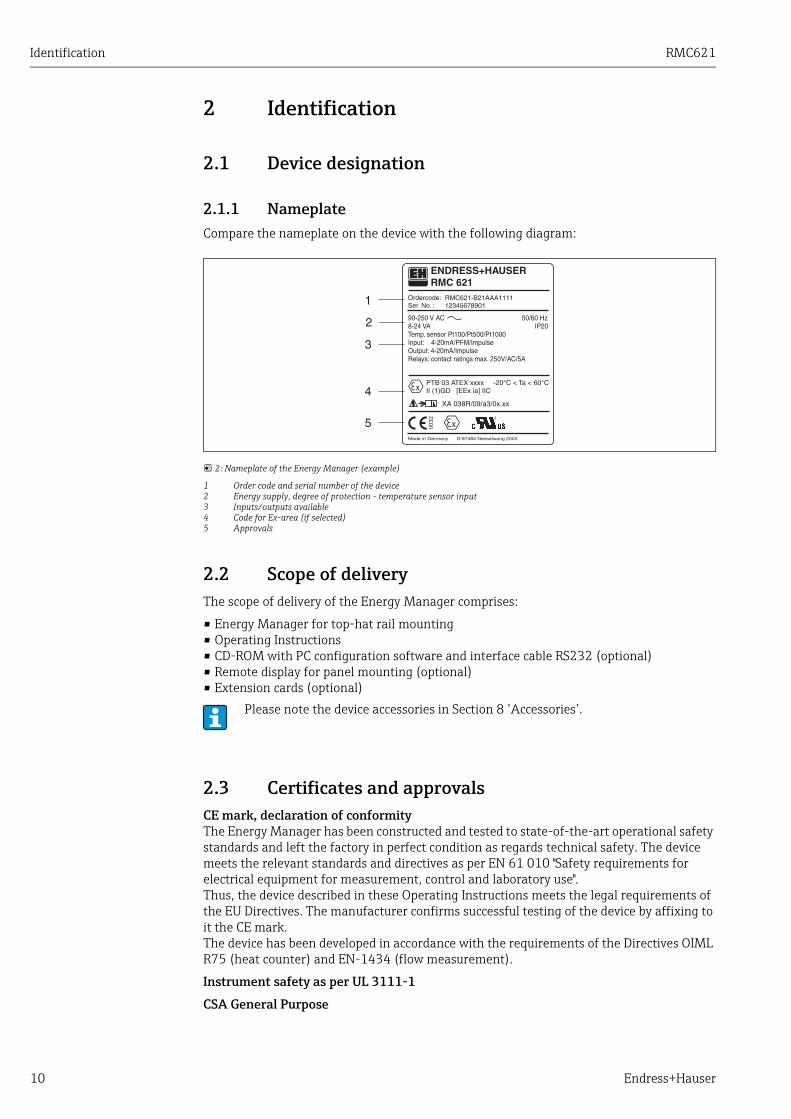
2.1.1 NameplateCompare the nameplate on the device with the following diagram:
2: Nameplate of the Energy Manager (example)
1 Order code and serial number of the device2 Energy supply, degree of protection - temperature sensor input3 Inputs/outputs available4 Code for Ex-area (if selected)5 Approvals
2.2 Scope of deliveryThe scope of delivery of the Energy Manager comprises:
• Energy Manager for top-hat rail mounting• Operating Instructions• CD-ROM with PC configuration software and interface cable RS232 (optional)• Remote display for panel mounting (optional)• Extension cards (optional)
2.3 Certificates and approvalsCE mark, declaration of conformityThe Energy Manager has been constructed and tested to state-of-the-art operational safety standards and left the factory in perfect condition as regards technical safety. The device meets the relevant standards and directives as per EN 61 010 "Safety requirements for electrical equipment for measurement, control and laboratory use".Thus, the device described in these Operating Instructions meets the legal requirements of the EU Directives. The manufacturer confirms successful testing of the device by affixing to it the CE mark.The device has been developed in accordance with the requirements of the Directives OIML R75 (heat counter) and EN-1434 (flow measurement).
Instrument safety as per UL 3111-1
CSA General Purpose
Please note the device accessories in Section 8 ’Accessories’.

RMC621 Installation
Endress+Hauser 11
3 Installation
3.1 Installation conditionsNOTICE
Device overheating when using extension cards‣ Aeration with an air flow of at least 0.5 m/s (1.6 fps) is required.
The permitted ambient temperature (see "Technical data" Section) must be observed when installing and operating. The device must be protected against the effects of heat.
3.1.1 DimensionsObserve the device length of 135 mm (5.31 in) (corresponds to 8TE). More dimensions can be found in Section 10 "Technical data".
3.1.2 Mounting locationTop-hat rail mounting as per EN 50 022-35 in the cabinet. The mounting location must be free from vibrations.
3.1.3 OrientationNo restrictions.
3.2 Installation instructionsNow snap the housing onto the top-hat rail by firstly hanging the device on the top-hat rail and then pressing it down gently until it engages (→ å 3, item 1 and 2).
3: Mounting device on top-hat rail
Installation RMC621
12 Endress+Hauser
3.2.1 Installing extension cards
NOTICEDevice overheating when using extension cards‣ Aeration with an air flow of at least 0.5 m/s (1.6 fps) is required.
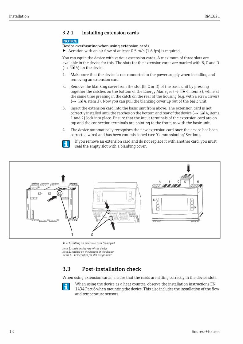
You can equip the device with various extension cards. A maximum of three slots are available in the device for this. The slots for the extension cards are marked with B, C and D (→ å 4) on the device.
1. Make sure that the device is not connected to the power supply when installing and removing an extension card.
2. Remove the blanking cover from the slot (B, C or D) of the basic unit by pressing together the catches on the bottom of the Energy Manager (→ å 4, item 2), while at the same time pressing in the catch on the rear of the housing (e.g. with a screwdriver) (→ å 4, item 1). Now you can pull the blanking cover up out of the basic unit.
3. Insert the extension card into the basic unit from above. The extension card is not correctly installed until the catches on the bottom and rear of the device (→ å 4, items 1 and 2) lock into place. Ensure that the input terminals of the extension card are on top and the connection terminals are pointing to the front, as with the basic unit.
4. The device automatically recognises the new extension card once the device has been corrected wired and has been commissioned (see ’Commissioning’ Section).
4: Installing an extension card (example)
Item 1: catch on the rear of the deviceItem 2: catches on the bottom of the deviceItems A - E: identifier for slot assignment
3.3 Post-installation checkWhen using extension cards, ensure that the cards are sitting correctly in the device slots.
If you remove an extension card and do not replace it with another card, you must seal the empty slot with a blanking cover.
When using the device as a heat counter, observe the installation instructions EN 1434 Part 6 when mounting the device. This also includes the installation of the flow and temperature sensors.

RMC621 Wiring
Endress+Hauser 13
4 Wiring
4.1 Quick wiring guide
5: Slot assignment (basic unit)
Terminal assignment
Terminal (item no.) Terminal assignment Slot Input
10 + 0/4 to 20 mA/PFM/pulse input 1 A top, front (A I) Current/PFM/pulse input 1
11 Ground for 0/4 to 20 mA/PFM/pulse input
81 Sensor power supply ground 1
82 24 V sensor power supply 1
110 + 0/4 to 20 mA/PFM/pulse input 2 A top, rear (A II) Current/PFM/pulse input 2
11 Ground for 0/4 to 20 mA/PFM/pulse input
81 Sensor power supply ground 2
83 24 V sensor power supply 2
1 + RTD power supply 1 E top, front (E I) RTD input 1
2 - RTD power supply 1
5 + RTD sensor 1
6 - RTD sensor 1
3 + RTD power supply 2 E top, rear (E II) RTD input 2
4 - RTD power supply 2
7 + RTD sensor 2
8 - RTD sensor 2
Terminal (item no.) Terminal assignment Slot Output - interface
101 - RxTx 1 E bottom, front (E III) RS485
102 + RxTx 1
103 - RxTx 2 RS485 (optional)
104 + RxTx 2
Wiring RMC621
14 Endress+Hauser
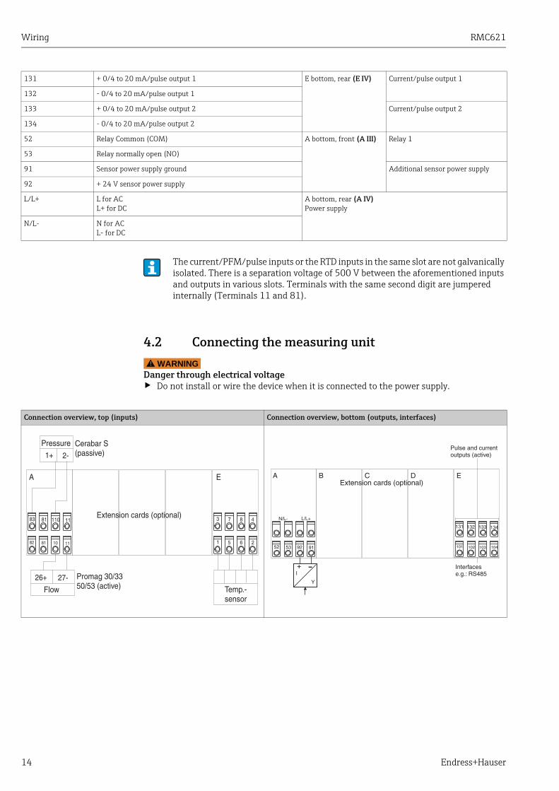
4.2 Connecting the measuring unit WARNING!
Danger through electrical voltage‣ Do not install or wire the device when it is connected to the power supply.
131 + 0/4 to 20 mA/pulse output 1 E bottom, rear (E IV) Current/pulse output 1
132 - 0/4 to 20 mA/pulse output 1
133 + 0/4 to 20 mA/pulse output 2 Current/pulse output 2
134 - 0/4 to 20 mA/pulse output 2
52 Relay Common (COM) A bottom, front (A III) Relay 1
53 Relay normally open (NO)
91 Sensor power supply ground Additional sensor power supply
92 + 24 V sensor power supply
L/L+ L for ACL+ for DC
A bottom, rear (A IV)Power supply
N/L- N for ACL- for DC
The current/PFM/pulse inputs or the RTD inputs in the same slot are not galvanically isolated. There is a separation voltage of 500 V between the aforementioned inputs and outputs in various slots. Terminals with the same second digit are jumpered internally (Terminals 11 and 81).
Connection overview, top (inputs) Connection overview, bottom (outputs, interfaces)

RMC621 Wiring
Endress+Hauser 15
4.2.1 Power supply connection
NOTICEDamage to the device through incorrect power supply connection‣ Before wiring the device, ensure that the supply voltage corresponds to the specification
on the nameplate‣ For the 90 to 250 V AC version (mains connection), a switch marked as a separator, as
well as an overvoltage organ (rated current ≤ 10 A), must be fitted in the supply line near the device (easy to reach).
6: Power supply connection
4.2.2 Connecting external sensors
Active sensors
Connection method for an active sensor (i.e. external power supply).
7: Connecting an active sensor, e.g. to input 1 (Slot A I).
Item 1: pulse signalItem 2: PFM signalItem 3: 2-wire transmitter (4 to 20 mA)Item 4: active sensor connection, e.g. optional Universal extension card in slot B (slot B I, → å 12)
Active and passive sensors with analog, PFM or pulse signal and RTD sensors can be attached to the device.Depending on the type of signal of the sensor in question, the terminals can be freely selected which means the Energy Manager can be used with great flexibility. This means that the terminals are not fixed to the sensor type, e.g. flow sensor-terminal 11, pressure sensor-terminal 12 etc. If the device is used as a heat counter in accordance with EN 1434, the connection regulations mentioned there apply.
Wiring RMC621
16 Endress+Hauser
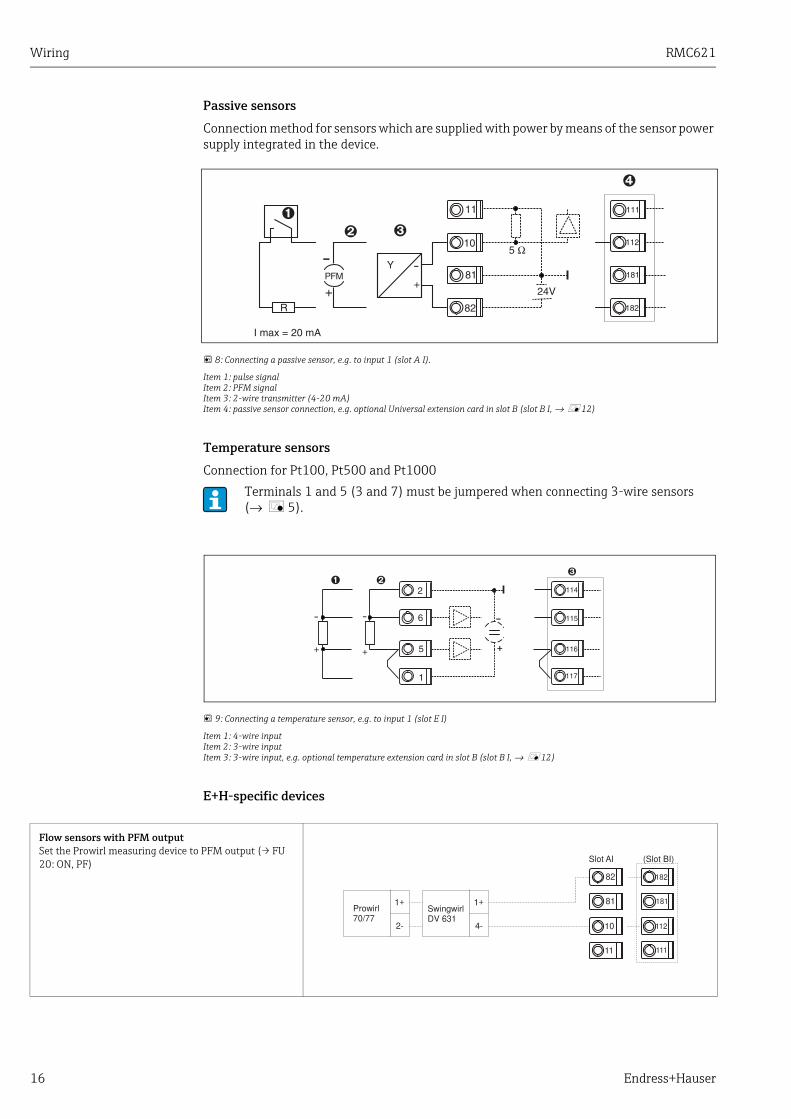
Passive sensors
Connection method for sensors which are supplied with power by means of the sensor power supply integrated in the device.
8: Connecting a passive sensor, e.g. to input 1 (slot A I).
Item 1: pulse signalItem 2: PFM signalItem 3: 2-wire transmitter (4-20 mA)Item 4: passive sensor connection, e.g. optional Universal extension card in slot B (slot B I, → å 12)
Temperature sensors
Connection for Pt100, Pt500 and Pt1000
9: Connecting a temperature sensor, e.g. to input 1 (slot E I)
Item 1: 4-wire inputItem 2: 3-wire inputItem 3: 3-wire input, e.g. optional temperature extension card in slot B (slot B I, → å 12)
E+H-specific devices
Terminals 1 and 5 (3 and 7) must be jumpered when connecting 3-wire sensors (→ å 5).
Flow sensors with PFM outputSet the Prowirl measuring device to PFM output (→ FU 20: ON, PF)

RMC621 Wiring
Endress+Hauser 17
Flow sensor with open collector outputSelect an appropriate dropping resistor R, so that Imax. = 20 mA is not exceeded.
Flow sensor with passive current output (4 to 20 mA)
Flow sensor with active current output (0/4 to 20 mA)
Flow sensor with active current output and status output (relay) for bidirectional flow measurementSelect an appropriate dropping resistor R, so that Imax. = 20 mA is not exceeded.
• Item A: direction signal• Item B: flow
When using a direction signal, select dropping resistor R such that the current output I is between 12 and 20 mA (e.g. 16 mA flows at R = 1.500 Ω)
Temperature sensor with temperature head transmitter (4 to 20 mA)

Wiring RMC621
18 Endress+Hauser
4.2.3 Connection of outputsThe device has two galvanically isolated outputs which can be configured as an analog output or an active pulse output. In addition, an output for connecting a relay and transmitter power supply is available. The number of outputs increases accordingly when the extension cards are installed (→ ä 19).
10: Connection of outputs
Item 1: pulse and current outputs (active)Item 2: passive pulse output (open collector, only on one extension card)Item 3: relay output (NO), e.g. slot A III (slot BIII, CIII, DIII on optional extension card)Item 4: transmitter power supply (transmitter power supply unit) output
Interface connection
• RS232 connectionThe RS232 is contacted by means of the interface cable and the jack socket on the front of the housing.
• RS485 connection• Optional: additional RS485 interface
Plug-in terminals 103/104, the interface is only active as long as the RS232 interface is not used.
• PROFIBUS connectionOptional connection of Energy Manager to PROFIBUS DP via the serial RS485 interface with the external module HMS AnyBus Communicator for Profibus (see Section 8 ’Accessories’).
• Optional: MBUSOptional connection to MBUS via 2nd RS485 interface
• Optional: ModbusOptional connection to Modbus via 2nd RS485 interface
Pressure sensor with passive current output (4 to 20 mA)
No communication via the RS232 interface (jack socket) is possible when the M-BUS or Modbus interface is enabled. The bus interface must be switched to RS232 at the device if data are being transmitted or read out with the PC configuration software.

RMC621 Wiring
Endress+Hauser 19
11: Interface connection
4.2.4 Extension card connection
12: Extension card with terminals
Terminal assignment of Universal extension card (RMC621A-UA); with intrinsically safe inputs (RMC621A-UB)
Terminal (item no..)
Terminal assignment Slot Input and output
182 24 V sensor power supply 1 B, C, D top, front (B I, C I, D I)
Current/PFM/pulse input 1
181 Sensor power supply ground 1
112 + 0/4 to 20 mA/PFM/pulse input 1
111 Ground for 0/4 to 20 mA/PFM/pulse input
183 24 V sensor power supply 2 B, C, D top, rear (B II, C II, D II)
Current/PFM/pulse input 2
181 Sensor power supply ground 2
113 + 0/4 to 20 mA/PFM/pulse input 2
111 Ground for 0/4 to 20 mA/PFM/pulse input
142 Relay 1 Common (COM) B, C, D bottom, front (B III, C III, D III)
Relay 1
143 Relay 1 normally open (NO)
152 Relay 2 Common (COM) Relay 2
153 Relay 2 normally open (NO)
131 + 0/4 to 20 mA/pulse output 1 B, C, D bottom, centre (B IV, C IV, D IV)
Current/pulse output 1 active
132 - 0/4 to 20 mA/pulse output 1
133 + 0/4 to 20 mA/pulse output 2 Current/pulse output 2 active
134 - 0/4 to 20 mA/pulse output 2
Wiring RMC621
20 Endress+Hauser
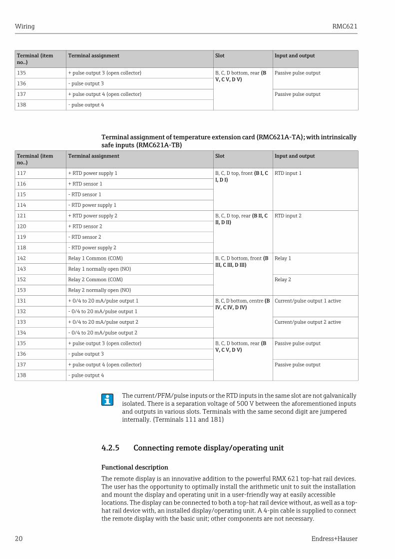
Terminal assignment of temperature extension card (RMC621A-TA); with intrinsically safe inputs (RMC621A-TB)
4.2.5 Connecting remote display/operating unit
Functional description
The remote display is an innovative addition to the powerful RMX 621 top-hat rail devices. The user has the opportunity to optimally install the arithmetic unit to suit the installation and mount the display and operating unit in a user-friendly way at easily accessible locations. The display can be connected to both a top-hat rail device without, as well as a top-hat rail device with, an installed display/operating unit. A 4-pin cable is supplied to connect the remote display with the basic unit; other components are not necessary.
135 + pulse output 3 (open collector) B, C, D bottom, rear (B V, C V, D V)
Passive pulse output
136 - pulse output 3
137 + pulse output 4 (open collector) Passive pulse output
138 - pulse output 4
Terminal (item no..)
Terminal assignment Slot Input and output
Terminal (item no..)
Terminal assignment Slot Input and output
117 + RTD power supply 1 B, C, D top, front (B I, C I, D I)
RTD input 1
116 + RTD sensor 1
115 - RTD sensor 1
114 - RTD power supply 1
121 + RTD power supply 2 B, C, D top, rear (B II, C II, D II)
RTD input 2
120 + RTD sensor 2
119 - RTD sensor 2
118 - RTD power supply 2
142 Relay 1 Common (COM) B, C, D bottom, front (B III, C III, D III)
Relay 1
143 Relay 1 normally open (NO)
152 Relay 2 Common (COM) Relay 2
153 Relay 2 normally open (NO)
131 + 0/4 to 20 mA/pulse output 1 B, C, D bottom, centre (B IV, C IV, D IV)
Current/pulse output 1 active
132 - 0/4 to 20 mA/pulse output 1
133 + 0/4 to 20 mA/pulse output 2 Current/pulse output 2 active
134 - 0/4 to 20 mA/pulse output 2
135 + pulse output 3 (open collector) B, C, D bottom, rear (B V, C V, D V)
Passive pulse output
136 - pulse output 3
137 + pulse output 4 (open collector) Passive pulse output
138 - pulse output 4
The current/PFM/pulse inputs or the RTD inputs in the same slot are not galvanically isolated. There is a separation voltage of 500 V between the aforementioned inputs and outputs in various slots. Terminals with the same second digit are jumpered internally. (Terminals 111 and 181)

RMC621 Wiring
Endress+Hauser 21
Installation/dimensions
Mounting instructions:• The mounting location must be free from vibrations.• The permitted ambient temperature during operation is -20 to +60C (-4 to +140 °F).• Protect the device against the effects of heat.
Procedure for panel mounting:1. Provide a panel cutout of 138+1.0 x 68+0.7 mm (5.43+0.04 x 2.68+0.03 in) (as per
DIN 43700), the installation depth is 45 mm (1.77 in).
2. Push the device with the sealing ring through the panel cutout from the front.
3. Hold the device horizontal and, applying uniform pressure, push the securing frame over the rear of the housing against the panel until the retaining clips engage. Make sure the securing frame is seated symmetrically.
13: Panel mounting
Wiring
14: Terminal plan of remote display/operating unit
Only one display/operating element can be attached to a top-hat rail device and vice versa (point-to-point).
Wiring RMC621
22 Endress+Hauser
The remote display/operating unit is connected directly to the basic unit with the cable supplied.
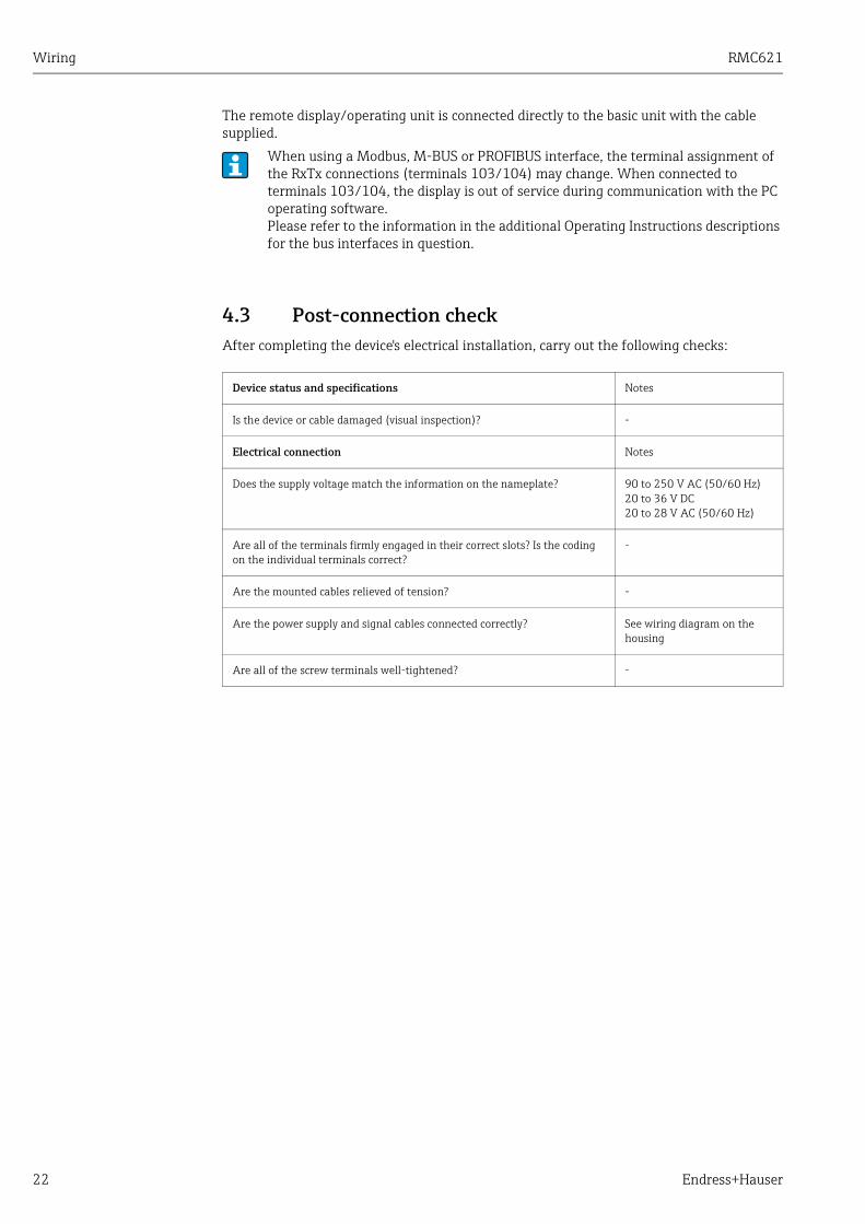
4.3 Post-connection checkAfter completing the device's electrical installation, carry out the following checks:
When using a Modbus, M-BUS or PROFIBUS interface, the terminal assignment of the RxTx connections (terminals 103/104) may change. When connected to terminals 103/104, the display is out of service during communication with the PC operating software.Please refer to the information in the additional Operating Instructions descriptions for the bus interfaces in question.
Device status and specifications Notes
Is the device or cable damaged (visual inspection)? -
Electrical connection Notes
Does the supply voltage match the information on the nameplate? 90 to 250 V AC (50/60 Hz)20 to 36 V DC20 to 28 V AC (50/60 Hz)
Are all of the terminals firmly engaged in their correct slots? Is the coding on the individual terminals correct?
-
Are the mounted cables relieved of tension? -
Are the power supply and signal cables connected correctly? See wiring diagram on the housing
Are all of the screw terminals well-tightened? -

RMC621 Operation
Endress+Hauser 23
5 Operation
5.1 Display and operating elements
15: Display and operating elements
Item 1: operating display: LED green, lights up when supply voltage applied.
Item 2: fault indicator: LED red, operating status as per NAMUR NE 44
Item 3: serial interface connection: jack socket for PC connection for device configuration and measured value read-out with the PC software
Item 4: display 160 x 80 dot-matrix display with dialog text for configuring as well as measured value, limit value and fault message display. Should a fault occur, the background lighting changes from blue to red. The size of the characters displayed depends on the number of measured values to be displayed (see Section 6.3.3 ’Display configuration’).
Item 5: input keys; eight soft keys which have different functions, depending on the menu item. The current function of the keys is indicated on the display. Only the keys which are required in the operating menu in question are assigned with functions or can be used.
Depending on the application and version, the Flow and Energy Manager offers a wide range of configuration options and software functions.Help text is available for nearly every operating item to assist when programming the device. This help text can be called up by pressing the "?" button. (The help text can be called up in every menu).Please note that the configuration options described below refer to a basic unit (without extension cards).

Operation RMC621
24 Endress+Hauser
5.1.1 Display
16: How the display of the energy computer appears
Item: 1: measured value displayItem: 2: display of configuration menu item– A: row of key icons– B: current configuration menu– C: configuration menu activated for selection (highlighted in black).
5.1.2 Key icons
5.2 Local operation
5.2.1 Entering textThere are two ways of entering text in the operating items (see: Setup → Basic set-up→ Text input):
a) Standard: individual characters (letters, numbers, etc.) in the text field are defined by scrolling through the entire row of characters with the up/down cursor until the desired character is displayed.b) Palm: a visual key field appears for entering text. The characters on this keyboard are selected with the cursors. (see "Setup → Basic set-up")
Using the Palm keyboard
Key icon Function
E Change to submenus and select operating items. Edit and confirm configured values.
Z Exit the current editing mask or the menu item currently active without saving any changes.
↑ Move the cursor up a line or a character.
↓ Move the cursor down a line or a character.
→ Move the cursor a character to the right.
← Move the cursor a character to the left.
? If Help text is available on an operating item, this is indicated with the question mark. The Help is called up by actuating this function key.
ΑΒ Change to the editing mode of the Palm keyboard
ij/iJ Key field for upper case/lower case (only with Palm)
½ Key field for numerical entries (only with Palm)

RMC621 Operation
Endress+Hauser 25
17: Example: editing an identifier with the Palm keyboard
1. Using the cursor keys, place the cursor in front of the character before which another character should be entered. If the entire text should be deleted and rewritten, move the cursor completely to the right. (→ å 17, graphic 1)
2. Press the AB key to enter the editing mode
3. Use the ij/IJ and ½ key to select upper/lower case or numerals. (→ å 17, graphic 2)
4. Use the cursors to select the key required and use the tick sign to confirm. If you want to delete text, select the key in the top right. (→ å 17, graphic 2)
5. Edit other characters in this way until the desired text has been entered.
6. Press the Esc key to switch from the editing mode to the display mode and accept changes with the 'tick' key. (→ å 17, graphic 1)
Notes• The cursor cannot be moved in the editing mode (→ å 17, graphic 2)! Use the Esc key to
go to the previous window (→ å 17, graphic 1) to move the cursor to the character which should be changed. Then confirm the AB key again.
• Special key functions:in key: change to overwrite modekey (top right): delete character
5.2.2 Lock configurationThe entire configuration can be protected against unintentional access by means of a four-digit code. This code is assigned in the submenu: Basic set-up → Code. All the parameters remain visible. If the value of a parameter should be changed, you are first asked for the user code.In addition to the user code, there is also the alarm limit code. When this code is entered, only the alarm limits are enabled for change.
18: Configuring the user code

Operation RMC621
26 Endress+Hauser
5.2.3 Operating exampleA detailed description of on-site operation with an application as an example can be found in Section 6.4 ’User-specific applications’.
5.3 Error message displayThe user can configure how the device responds in the event of an error. The measuring range can be freely defined for all analog inputs and the alarm response can be defined for when the system exceeds the range limits. In addition, the alarm response can also be configured if special process errors occur (e.g. wet steam condition).The alarm response affects the display, counters and outputs.The alarm response of the device is defined in the operating item Setup…Basic Setup…Alarm Response.
Factory setting:
Process errors are always displayed as notice messages, i.e. the errors do not have any effect on the counters and outputs. The NAMUR guidelines apply for the range limits of the analog inputs (current). (3.6/3.8/20.5/21mA)
Free configuration:
The alarm response of the inputs and outputs, as well as of the application-related process errors, can be configured individually. In this way, the behavior of current value calculation, counters and outputs can be defined explicitly.
Alarm response
A distinction is made between two types of alarm, namely "Notice" and "Fault"
Symbols for displaying error messages
If the user resets the system from "Free Configuration" to "Factory Setting", all the operating items for setting the alarm response are reset to the default value (overwritten!).
Notice Fault
Current values The current process values are calculated on the basis of the response configured (last value, fixed value, extrapolation). See under "Inputs".
Counters Normal operation (counters continue to count)
Deficits are recorded on a separate disturbance quantity counter (this can be shown on the display and be output via the pulse output)The response of the standard counters can be adjusted (default: counter stop).
Outputs Outputs are not affected Outputs react in accordance with the failsafe mode configured
Display Color change and alarm message display can be configured
Color change to red, alarm message display can be configured
Icons appear along the top edge of the display next to the display parameter affected by the error which has occurred.
Signal overshooting (x > 20.5 mA) or undershooting (x < 3.8 mA)
RMC621 Operation
Endress+Hauser 27
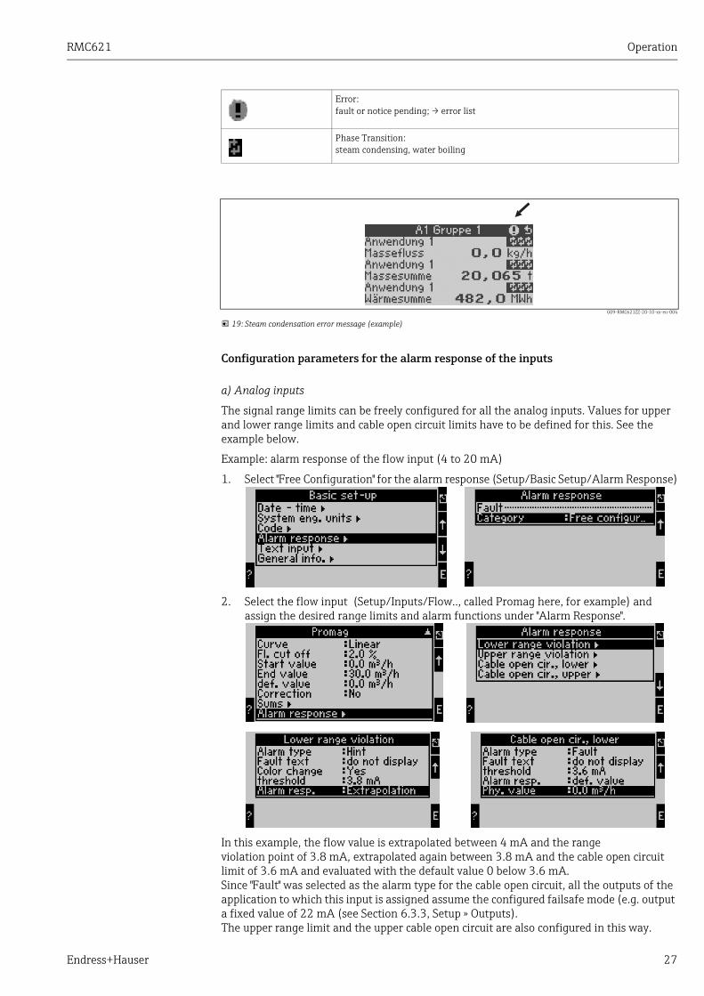
G09-RMC621ZZ-20-10-xx-en-004
19: Steam condensation error message (example)
Configuration parameters for the alarm response of the inputs
a) Analog inputs
The signal range limits can be freely configured for all the analog inputs. Values for upper and lower range limits and cable open circuit limits have to be defined for this. See the example below.
Example: alarm response of the flow input (4 to 20 mA)
1. Select "Free Configuration" for the alarm response (Setup/Basic Setup/Alarm Response)
2. Select the flow input (Setup/Inputs/Flow.., called Promag here, for example) and assign the desired range limits and alarm functions under "Alarm Response".
In this example, the flow value is extrapolated between 4 mA and the range violation point of 3.8 mA, extrapolated again between 3.8 mA and the cable open circuit limit of 3.6 mA and evaluated with the default value 0 below 3.6 mA.Since "Fault" was selected as the alarm type for the cable open circuit, all the outputs of the application to which this input is assigned assume the configured failsafe mode (e.g. output a fixed value of 22 mA (see Section 6.3.3, Setup » Outputs).The upper range limit and the upper cable open circuit are also configured in this way.
Error:fault or notice pending; → error list
Phase Transition:steam condensing, water boiling

Operation RMC621
28 Endress+Hauser
b) Temperature inputs
The response in the event of a cable open circuit (infinite resistance) can be defined for the temperature inputs (e.g. PT100) (the measuring range limits are fixed).
c) Pulse inputs
The alarm response cannot be defined for pulse inputs (incl. PFM signal), i.e. a cable open circuit or a frequency of 0 Hz are interpreted identically by the device.
Configuration parameters for the alarm response of the applications
The alarm response can be defined for the following process errors under Setup/Applications/Alarm Response.Steam: wet steam alarm, phase transitionGas: range overshoot
Event Buffer
Main Menu → Diagnosis → Event BufferIn the event buffer, the last 100 events, i.e. fault messages, notices, limit values, power failure etc. are recorded in chronological order with the time of occurrence and counter reading.
Error list
The error list provides assistance in quickly localizing current device errors. Up to ten alarms are listed in the error list in chronological order. In contrast to the event buffer, only the errors currently pending are displayed, i.e. rectified errors are cleared from the list.
5.4 CommunicationIn all devices and device versions, the parameters can be configured, altered and read out via the standard interface with the aid of PC operating software and an interface cable (see Section 8 ’Accessories’). This is recommended in particular if extensive settings are to be made (e.g. when commissioning).There is the additional option of reading out all the process and display values via the RS485 interface via MBUS, MODBUS or an external PROFIBUS module (HMS AnyBus Communicator for PROFIBUS-DP) (see 'Accessories' Section).
If an error occurs, the system continues calculating with the configured substitute value. At the same time, the error status (H = notice / S = fault) of all the inputs and the application is checked. If one of these statuses signals a fault, the device reacts as follows:
• Disturbance quantity counter records the deficits• The analog output outputs an error current• The status byte at the bus output is set to an 'invalid' value

RMC621 Operation
Endress+Hauser 29
Configuring a device with PC operating software Readwin 2000
1. Select a device » Display/Change Unit Setup/New Unit F2
2. Create a unit group (folder) and select Create New Unit F2. Fill in the "Unit Identifier" and select the serial interface.
3. Configure the interface parameters.
4. The device address and the baudrate must match.When using in a BUS system, under certain circumstances no direct communication between the PC and device is possible after the initial configuration. Please refer to the information in the additional Operating Instructions descriptions for the bus interfaces in question.
5. Configure the device and click the third icon from the left to transfer the settings.
Detailed information for configuring the device using the PC operating software can be found in the accompanying Operating Instructions which are also located on the data carrier.
Commissioning RMC621
30 Endress+Hauser
6 Commissioning
6.1 Function checkMake sure that all post-connection checks have been carried out before you commission your device:
• See Section 3.3 ’Post-installation check’• Checklist Section 4.3 ’Post-connection check’
6.2 Switching on the measuring device
6.2.1 Basic unitOnce the operating voltage is applied, the green LED (= device operating) lights up if no fault is present.
• When the device is first commissioned, the prompt "Please set up device" appears on the display. Program the device as per the description → ä 31.
• When commissioning a device already configured or preset, measuring is immediately started as per the settings. The values of the display group currently set appear on the display. By pressing any key, you get to the navigator (quick start) and from there back to the Main menu (→ ä 31).
6.2.2 Extension cardsWhen the operating voltage is applied, the device automatically recognises the installed and wired extension cards. You can now follow the prompt to configure the new connections or perform the configuration at a later date.
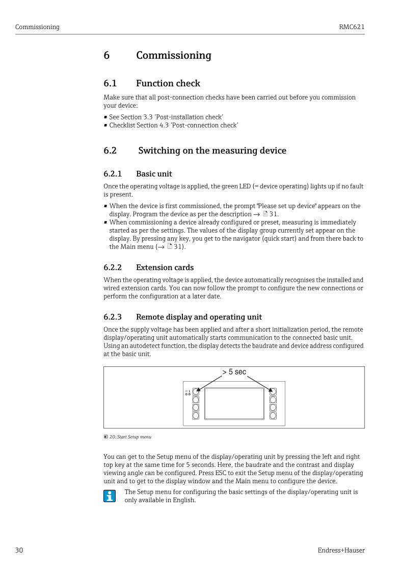
6.2.3 Remote display and operating unitOnce the supply voltage has been applied and after a short initialization period, the remote display/operating unit automatically starts communication to the connected basic unit. Using an autodetect function, the display detects the baudrate and device address configured at the basic unit.
20: Start Setup menu
You can get to the Setup menu of the display/operating unit by pressing the left and right top key at the same time for 5 seconds. Here, the baudrate and the contrast and display viewing angle can be configured. Press ESC to exit the Setup menu of the display/operating unit and to get to the display window and the Main menu to configure the device.
The Setup menu for configuring the basic settings of the display/operating unit is only available in English.

RMC621 Commissioning
Endress+Hauser 31
Error messages
After switching on or configuring the device, the message "Communication Problem" appears briefly on the remote display/operating unit until a stable connection has been established.If this error message is displayed during ongoing operation, please check the wiring.
6.3 Device configurationThis section describes all the configurable device parameters with the associated value ranges and factory settings (default values).Please note that the parameters available for selection, e.g. the number of terminals, depend on the device version (→ ä 30 Extension cards).
Function matrix
21: Function matrix (extract) for on-site Energy Manager configuration. A detailed function matrix can be found in the Appendix.
6.3.1 Navigator (quick start)
22: Quick start to configuration via the Navigator menu of the Energy Manager.
In the operating mode of the Energy Manager (measured value displayed), the operating window "Navigator" opens up by pressing any key: the Navigator menu offers quick access to important information and parameters. Pressing one of the keys available takes you directly to the following items:
Function (menu item) Description
Group For selecting individual groups with display values.

Commissioning RMC621
32 Endress+Hauser
The contents of the groups with display values can only be defined in the Setup → Display menu. A group comprises a maximum of eight process variables which are displayed in a window in the display. When commissioning the device, 2 groups with the most important display parameters are automatically created when an application is selected. Automatically created groups are also marked with a value in brackets (A1..3) which refers to the application, e.g. Group 1 (A1) means Group 1 with display values for Application 1.The settings for the display functionalities, e.g. contrast, scrolling display, special groups with display values etc. are also made in the menu Setup → Display.
6.3.2 Main menu - DiagnosisThe Diagnosis menu is used to analyse the device functionality, such as locating device malfunctions.
Display For displaying the groups alternately, setting in the setup menu"Display".
Error list For quickly localising current device errors.
Counter val For reading off and, if necessary, resetting all the totalizers.
Menu Main menu for configuring the device.
When commissioning, the prompt "Please set up device" is displayed. Confirming this message takes you to the Navigator menu. Select ’Menu’ here to get to the Main menu.A device already configured is in the display mode as standard. The device changes to the Navigator menu as soon as one of the eight operating keys is pressed. From here, you get to the Main menu by selecting ’Menu’.
If you continue navigating through the Main menu, the message "If you change the application, the respective counters will be reset" is displayed. Confirming this message takes you to the Main menu.
Function (menu item) Parameter setting Description
Terminal info A10 Lists all the terminals of the device and the connected sensors. Display the signal values present (in mA, Hz, Ohm) by pressing thekey i.
Event buffer Log of all the events, e.g. error messages, parameter changes, etc. in chronological order. (ring buffer with approx. 100 values, cannot be deleted!)
Program info Displays the device data such as program, name, software version, date and time.
Function (menu item) Description

RMC621 Commissioning
Endress+Hauser 33
6.3.3 Main menu - Setup
CAUTION!
Malfunction of the measuring point in the case of incorrect parameterization‣ If you change configuration parameters, check whether this has an affect on other
parameters and your overall measuring system.
The Setup menu is used for configuring the Energy Manager. The following subsections and tables list and describe all the configuration parameters of the Energy Manager.
Procedure when configuring the Energy Manager
1. Select system units (device settings).
2. Configure inputs (flow, pressure, temperature), i.e. assign terminals to the sensors and scale the input signals, if necessary configure default values for pressure and temperature.
3. Application (e.g. gas/norm volume) and medium (e.g.methane). (If no suitable medium is stored, a special medium can be selected in the Main menu).
4. Configure application, i.e. assign the configured inputs (sensors) .
5. Configure outputs (analog, pulse or relay/limit values).
6. Check display settings (values are preset automatically).
7. Make optional device settings (e.g. communication settings).
Set-up → Basic set-up
The basis data of the device are defined in this submenu.
Factory settings are indicated in bold.
Function (menu item) Parameter setting Description
Date-Time
Date DD.MM.YYDD.MM.YY
For configuring the current date (country-specific).Important for summertime/wintertime changeover
Time SS:MM Current time for the real time clock of the device.
Summertime/normal time changeover
• Changeover Off - Manual - Auto. Kind of time changeover.
• Region Europe - USA Displays the changeover date from normal time (NT) to summertime (ST) and vice versa. This function depends on the region selected.
• NT→STST→NT– Date
– Time
• 31.03 (Europe)07.04 (USA)
• 27.10 (Europe27.10 (USA)
• 02:00
Takes into consideration the summertime/normal time changeover in Europe and USA at different times. This can only be selected if summertime/normal time changeover is not set to ’Off’.
Time of changeover. This can only be selected if summertime/normal time changeover is not set to ’Off’.
System eng. units
System eng. units Metric American User defined input
Sets the unitary system. "User defined input" means that a picklist with different unitary systems, incl. time basis and format, appears in the individual operating items.
Code
• User
• Alarm lim.
0000 - 9999
0000 - 9999
Device operation is only enabled once the previously defined code has been entered.Only the alarm limits are enabled for configuration. All other parameters remain locked.

Commissioning RMC621
34 Endress+Hauser
S-DAT module
End set-up AutomaticOn request
Saves the settings automatically when you exit the setup or confirm a prompt/question.
Save YesNo
Write data to the S-DAT module.
Read in Transfer counter readings and operating data from the module to the device.
Op. data DateTimeRead in
S-DAT data Prog. name, Prog. ver., CPU No.
Program name, program version and CPU number of the S-DAT module.
Alarm response
Fault category Default set-up - User defined input
Alarm response when process errors occur. As per the factory setting, all process errors are signalled by a warning message. By selecting "User defined input", additional operating items appear in the inputs and the application to assign a different fault category (fault message) to the individual process errors (see Section 5.3 ’Error message display’).
Text input
StandardPalm
Selects the way of entering text:
• Standard:Per parameter item, runs up or down the row of characters until the desired character appears.
• Palm:The desired character can be selected from the visual key field with the cursors.
General info
Unit ID Assigns a device name (max. 12 characters long).
TAG number Assigns a TAG number, as in wiring diagrams for example (max. 12 characters long).
Prog. name Name which is saved in the PC operating software along with all the settings.
SW version Software version of your device.
SW option Information as to which extension cards are installed.
CPU No.: The CPU number of the device is used as an identifier. It is saved with all the parameters.
Series No.: This is the serial number of the device.
Run time
1. Unit
2. LCD
1. Information on how long the device has been in operation (protected by service code.)
2. Information on the operating time of the device display (protected by service code.)
Function (menu item) Parameter setting Description

RMC621 Commissioning
Endress+Hauser 35
Setup → Inputs
Flow inputs
The Energy Manager processes all common flow measurement methods (volume, mass, differential pressure). You can connect up to three flow transmitters at the same time. There is also the option of using just one flow transmitter in various applications, see ’Terminals’ menu item).
Special flow meters
Item for very exact flow based on differential pressure method with compensation calculation as per ISO 5167 as well as splitting range function for extending the measuring range, e.g. for orifice measurement (up to three DP transmitters) and possibility of computing the mean value from several DPTs.
Pressure inputs
A maximum of three pressure sensors can be connected. One sensor can also be used for two or all three applications, see the ’Terminal’ item in the related table.
Temperature inputs
For connecting between two and six (max.) temperature sensors (RTD). A sensor can be used in several applications here, see the ’Terminal’ item in the related table.
Flow inputs
Depending on the version, 4 to 10 current, PFM, pulse and RTD inputs are available in the energy computer to record the flow, temperature and pressure signals.
Function (menu item) Parameter setting Description
Flow inputs Flow 1, 2, 3 Configuration of individual flow transmitters.
Identifier Name of the flow transmitter (max. 12 characters).
DPT VolumetricMassProcess Value
Setting of the measuring principle of your flow transmitter or as to whether the flow signal is in proportion to the volume, (e.g. vortex, EFM, turbine) or mass (e.g. Coriolis). By selecting "Process Value", the calculated mass flow of another application can be assigned to the input (for details, see Section 11.2 'Flow measurement configuration').The mass input always has to be assigned to an application.
Signal Select4-20 mA0-20 mAPFMPulseDefault
Selects the signal of the flow transmitter.
Terminals NoneA-10; A-110; B-112;B-113; C-112; C-113; D-112; D-113
Defines the terminal to which the flow transmitter in question is connected. It is possible to use a transmitter (flow signal) for several applications. For this, in the application in question, select the terminal where the transmitter is located (multiple selection possible).
Curve LinearSqr. root
Select the curve of the flow transmitter used.
Unit l/...; hl/...; dm3/...; m3/...; bbl/...; gal/...; igal/...; ft3/...; acf/...
Flow unit in format: selected unit by XOnly visible if the "User defined input" system unit has been selected.
kg, t, lb, ton (US) Can only be selected for flow transmitter/mass

Commissioning RMC621
36 Endress+Hauser
Time base .../s; .../min; .../h; .../d Time basis for the flow unit in the format: X per time unit selected.Only visible if the "User defined input" system unit has been selected.
gal/bbl 31.5 (US), 42.0 (US), 55.0 (US), 36.0 (Imp), 42.0 (Imp), User def.31.0
Definition of technical unit Barrel (bbl), given in gallons per barrel.US: US gallonsImp: Imperial gallonsUser def.: free to set the conversion factor.
Format 9; 9.9; 9.99; 9.999 Number of places after the decimal pointOnly visible if the "User defined input" system unit has been selected.
Meter coeff. Pulse valueK-factor
Select the reference variable for the pulse value.Pulse value (unit/pulse)K-factor (pulse/unit)
Pulse value 0.001 to 99999 Setting as to what volume flow (in dm3 or litre) a pulse of the flow transmitter corresponds to.Only available for Pulse signal.
K Fact. unit Pulse/dm3
Pulse/ft3
K-factor 0.001 to 9999.9 Enter the pulse value of the vortex sensor. You can find this value on your flow sensor.This can only be selected for the PFM signal.For vortex sensors with pulse signal, the reciprocal value of the K-factor (in pulse/dm3) is entered as a pulse value.
Threshold 0,0000 to 9999999.99999999.9
Only for Device type = process value
Start value 0.0000 to 999999 Start value for the volume flow (differential pressure) with 0 or 4 mA.This can only be selected for the 0/4 to 20 mA signal.
End value 0.0000 to 999999 End value for the volume flow (differential pressure) with 20 mA.This can only be selected for the 0/4 to 20 mA signal.
Flow cut off 0.0 to 99.9%4.0 %
Below the set value, the flow is no longer recorded or 0 is set. Depending on the type of flow transmitter, the flow cutoff can be set in % of the full scale value of the flow measuring range or as a fixed flow value (e.g. in m3/h).
Correction YesNo
Possibilities for correcting the flow measurement by offset, signal damping, flow cut off, sensor expansion coefficient and correction table for curve description.
Signal damp 0 to 99 s Time constant of the first order low pass for the input signal. This function is used to reduce display fluctuations in the event of severely fluctuating signals.This can only be selected for the 0/4 to 20 mA signal.
Offset -9999.99 to 9999.99 Shifts the zero point of the response curve. This function is used to adjust sensors.This can only be selected for the 0/4 to 20 mA signal.
Correction YesNo
Possibility for correcting the flow measurement. If "YES" is selected, the sensor curve can be defined in the correction table and there is the possibility of compensating the temperature effect on the flow transmitter (see "Exp. coeff.")
Expan. coeff. 0 to 9.9999e-XX Correction factor for compensating the temperature effect on the flow transmitter. This factor is often indicated on the nameplate for vortex flowmeters, for example. If no value is known for the expansion coefficient or if this has already been compensated by the device itself, please set 0 here.Default: 4.88e-05Note! Only active if correction setting is active.
Function (menu item) Parameter setting Description

RMC621 Commissioning
Endress+Hauser 37
Special flow meters
Table UseNot used
If the flow curve of your transmitter deviates from the ideal pattern (linear or square root), this can be compensated by entering a correction table.For details, see the 'Correction tables' in Section 11.2.1.
No. of rows 01 - 15 Number of points in the table.
Corr. tab. pulse Point (used/delete)Current/flow frequency/k-factor
If the flow curve of your transmitter deviates from the ideal pattern (linear or square root), this can be compensated by entering a correction table. The parameters in the table depend on the flow transmitter selected.
• Analog signal, linear curveUp to 15 value pairs (current/flow)
• Pulse signal, linear curveUp to 15 value pairs (frequency/k-factor or frequency/pulse value).
For details, see the 'Correction tables' in Section 11.2.1.
Sums UnitFormatTotalSignal resetTerminals
Possibility of configuring or resetting the totalizers for the volume flow. Signal reset, i.e. resetting the totalizer by an input signal (e.g. remote read-out of totalizers with subsequent reset).(Terminal for this input signal only active if "Signal Reset = YES")
Alarm response
Lower Range ViolationUpper Range ViolationLower Cable Open CircuitUpper Cable Open Circuit
Alarm TypeColor ChangeFault Text
For this input, individually specify the signal range limits and how alarms should be displayed when faults occur.Only active if the option 'User defined input' was selected in the 'Alarm Response' menu item in Setup → Basic Setup.
Alarm Type FaultNotice
Configurable fault message, deficit counter, color change (red), alarm text display, stop counter (yes/no).
Color Change YesNo
Select whether the alarm should be signaled by a color change from blue to red.Only active if the ’Notice’ alarm type has been selected.
Fault Text Display+AcknowledgeDo Not Display
Select whether an alarm message should appear to describe the fault when an alarm occurs. This is cleared (acknowledged) by pressing a key.
Function (menu item) Parameter setting Description
Special flow meters Differential pressure 1, 2, 3Mean flow
Configuration of individual or several differential pressure transmitters (DPT).Only use if your DP transmitter outputs a pressure-scaled signal (mbar, inH20 etc.)
Identifier Name of the flow transmitter (max. 12 characters).
Meas. point SelectDPTSplitting Range
Select whether one DP transmitter or several DPTs are used for extending the measuring range (Splitting Range).(See Section 11.2.1 for details of the 'Splitting Range')
Differential pressure transmitter
Function (menu item) Parameter setting Description

Commissioning RMC621
38 Endress+Hauser
Flow type PitotOrifice corner tapOrifice D2Orifice flange tapISA 1932 nozzleLong rad. nozzle Venturi nozzleVenturi tube (cast)Venturi tube (mach.)Venturi tube (steel)V-cone
Type of differential pressure transmitterThe data in brackets refer to the type of Venturi tube.
Medium WaterSteamGas (Argon, etc.)Liquid (Propane, etc.)
Select the medium for which the flow should be measured.
Signal Select4-20 mA0-20 mAPFMPulseDefault
See Setup ’Flow inputs’
Terminals NoneA-10; A-110; B-112;B-113; C-112; C-113; D-112; D-113
See Setup ’Flow inputs’
Curve LinearSqr. root
Curve of the DP transmitter used.Please observe information in Section 11.2.1!
Time base .../s; .../min; .../h; .../d See Setup ’Flow inputs’
Unit l/...; hl/...; dm3/...; m3/...; bbl/...; gal/...; igal/...; ft3/...; acf/...
See Setup ’Flow inputs’Only visible if the "User defined input" system unit has been selected.
kg, t, lb, ton (US) Can only be selected for flow transmitter/mass
gal/bbl 31.5 (US), 42.0 (US), 55.0 (US), 36.0 (Imp), 42.0 (Imp), User def.31.0
See Setup ’Flow inputs’
Format 9; 9.9; 9.99; 9.999 See Setup ’Flow inputs’Only visible if the "User defined input" system unit has been selected.
Rng. units mbarin/H20
Unit of differential pressure
Range start mbarin/H20
Start value for the differential pressure with 0 or 4 mA.
Range end mbarin/H20
End value for the differential pressure with 20 mA.
Factor K-factor for describing the resistance coefficient of E+H Pitot tubes (see data sheet).
Correction YesNo
Possibilities for correcting the flow measurement by offset, signal damping, flow cut off, expansion coefficient of the device (e.g. orifice plate) and correction table for curve description.
Flow cut off 0.0 to 99.9%4.0 %
Below the set value, the flow is no longer recorded or 0 is set. Depending on the type of flow transmitter, the flow cutoff can be set in % of the full scale value of the flow measuring range or as a fixed flow value (e.g. in m3/h).
Signal damp 0 to 99 s Time constant of the first order low pass for the input signal. This function is used to reduce display fluctuations in the event of severely fluctuating signals.This can only be selected for the 0/4 to 20 mA signal.
Function (menu item) Parameter setting Description
RMC621 Commissioning
Endress+Hauser 39
Offset -9999.99 to 9999.99 Shifts the zero point of the response curve. This function is used to adjust sensors.This can only be selected for the 0/4 to 20 mA signal.
Table UseNot used
If the flow curve of your transmitter deviates from the ideal pattern (linear or square root), this can be compensated by entering a correction table.For details, see Setup ’Flow inputs’.
Pipe data Inner dia.Geom. ratio
Enter the internal diameter of the pipe.Enter the diameter ratio (d/D = β) of the differential pressure transmitter, data in the data sheet of the DP transmitter.In dynamic pressure measurements, the K-factor must be given to describe the resistance coefficient of the probe (see Section 11.2.1 for details).
Coefficient Fixed valueTable
Flow coefficient c for calculating the flow.Only if using a V-cone flow transmitter.
Coeff. (c) 0.0001 to 99999 Enter the flow coefficient c.
Num. coeff. 01 - 15 Number of points in the table.
Coeff. tab. Points(used/delete)Reynolds No./coefficient
Table for describing the flow coefficient depending on the Reynolds number.For details on the V-cone calculation method, see Section 11.2.1
Sums UnitFormatActualTotalSignal resetTerminals
See Setup ’Flow inputs’
Splitting range
Splitting range Splitting range or automatic measuring range switching for differential pressure measuring devices.See Section 11.2.1 for details of the 'Splitting Range'.
Rng.1 Term. A-10; A-110; B-112;B-113; C-112; C-113; D-112; D-113
Terminal for connecting the differential pressure transmitter with the smallest measuring range
Rng.2 Term. A-10; A-110; B-112;B-113; C-112; C-113; D-112; D-113
Terminal for connecting the differential pressure transmitter with the second largest measuring range
Rng.3 Term. A-10; A-110; B-112;B-113; C-112; C-113; D-112; D-113
Terminal for connecting the differential pressure transmitter with the largest measuring range
Range 1 (2, 3) start 0.0000 to 999999 Start value for the differential pressure at 0 or 4 mA, defined for the pressure transmitter in range 1 (2, 3)Only active after a terminal has been assigned.
Range 1 (2, 3) end 0.0000 to 999999 End value for the differential pressure at 20 mA, defined for the pressure transmitter in range 1 (2, 3)Only active after a terminal has been assigned.
Correction YesNo
Possibilities for correcting the flow measurement by offset, signal damping, flow cut off, sensor expansion coefficient and correction table for curve description.see Setup ’Differential pressure transmitter’
Pipe data Units (mm/inch)Inner dia.Geom. ratioK-factor
See Setup ’Differential pressure transmitter’.
Function (menu item) Parameter setting Description
Commissioning RMC621
40 Endress+Hauser
Pressure inputs
Sums UnitFormatActualTotalSignal resetTerminals
See Setup ’Flow inputs’.
Alarm response See Setup ’Flow inputs’.
Mean flow
Identifier Mean flow Name for computing the mean value from several flow signals (max. 12 characters).
Number Unused2 sensors3 sensors
Mean value computed from several flow signals(See Section 11.2.1 for details of the 'Mean value computation')
Sums UnitFormatActualTotalSignal resetTerminals
See Setup ’Flow inputs’.
Function (menu item) Parameter setting Description
Identifier Pressure 1-3 Name of pressure sensor, e.g. ’pressure in’ (max. 12 characters).
Signal Select4-20 mA0-20 mADefault
Selects the signal of the pressure sensor. If ’Default’ is set, the device works with a fixed default pressure.
Terminals NoneA-10; A-110; B-112;B-113; C-112; C-113; D-112; D-113
Defines the terminal for connecting the pressure sensor. It is possible to use a sensor signal for several applications. For this, in the application in question, select the terminal where the sensor is located. (multiple selection possible)
Unit bar; kPa; kg/cm2; psi; bar (g); kPa (g); psi (g)
Physical unit of the measured pressure.
• (a) = appears on the display if ’Absolute’ was selected as the type. Refers to the absolute pressure.
• (g) = gauge, appears on the display if ’Relative’ was selected as the type. Refers to the relative pressure.
(a) or (g) appears automatically on the display depending on the type selected.Only visible if the "User defined input" system unit is selected.
Type AbsoluteRelative
Indicates whether the measured pressure is absolute or relative (gauge) pressure. With relative pressure measurement, the atmospheric pressure has to be entered afterwards.
Format 9; 9.9; 9.99; 9.999 Number of places after the decimal pointOnly visible if the "User defined input" system unit is selected.
Start value 0.0000 to 999999 Start value for the pressure with 0 or 4 mA.This can only be selected for the 0/4 to 20 mA signal.
End value 0.0000 to 999999 End value for the pressure with 20 mA.This can only be selected for the 0/4 to 20 mA signal.
Signal damp 0 to 99 s Time constant of the first order low pass for the input signal. This function is used to reduce display fluctuations in the event of severely fluctuating signals.This can only be selected for the 0/4 to 20 mA signal.
Function (menu item) Parameter setting Description
RMC621 Commissioning
Endress+Hauser 41
Temperature inputs
Offset -9999.99 to 9999.99 Shifts the zero point of the response curve. This function is used to adjust sensors.This can only be selected for the 0/4 to 20 mA signal.
Atm. press. 0.0000 to 10000.01.013
Configuration of the ambient pressure (in bar) present at the device installation location.Item is only active if ’relative’ is selected as the type.
Default -19999 to 19999 Sets the default pressure which is worked with if the sensor signal fails and the ’Default’ signal is set.
Alarm response See Setup ’Flow inputs’.
Mean value Unused2 sensors3 sensors
Mean value computed from several pressure signals(See Section 11.2.1 for details of the 'Mean value computation')
Function (menu item) Parameter setting Description
Identifier Temperature 1-6 Name of temperature sensor, e.g. ’Temp 1’ (max. 12 characters).
Signal Select4-20 mA0-20 mAPt100Pt500Pt1000Default
Selects the signal of the temperature sensor. If ’Default’ is set, the device works with a fixed default temperature.
Sensor type 3-wire4-wire
Configures the sensor connection in 3-wire or 4-wire technology.Can only be selected for the Pt100/Pt500/Pt1000 signal.
Terminals NoneA-10; A-110; B-112; B-113; C-112; C-113; D-112; D-113; B-117; B-121; C-117; C-121; D-117; D-121; E-1-6; E-3-8
Defines the terminal for connecting the temperature sensor. It is possible to use a sensor signal for several applications. For this, in the application in question, select the terminals where the sensor is located (multiple selection possible).The term in brackets X-1X (e.g. A-11) describes a current input, the term X-2X (e.g. E-21) a pure temperature input. The type of input depends on the extension cards.
Unit °C; K; °F Physical unit of the measured temperature.Only visible if the "User defined input" system unit is selected.
Format 9; 9.9; 9.99; 9.999 Number of places after the decimal pointOnly visible if the "User defined input" system unit is selected.
Signal damp 0 to 99 s0 s
Time constant of the first order low pass for the input signal. This function is used to reduce display fluctuations in the event of severely fluctuating signals.This can only be selected for the 0/4 to 20 mA signal.
Start value -9999.99 to 999999 Start value for the temperature with 0 or 4 mA.This can only be selected for the 0/4 to 20 mA signal.
End value -9999.99 to 999999 End value for the temperature with 20 mA.This can only be selected for the 0/4 to 20 mA signal.
Offset -9999.99 to 9999.990.0
Shifts the zero point of the response curve. This function is used to adjust sensors.This can only be selected for the 0/4 to 20 mA signal.
Default -9999.99 to 9999.9920 °C or 70 °F
Sets the temperature which is worked with if the sensor signal fails and the ’Default’ signal is set.
Alarm response See Setup ’Flow inputs’.
Function (menu item) Parameter setting Description
Commissioning RMC621
42 Endress+Hauser
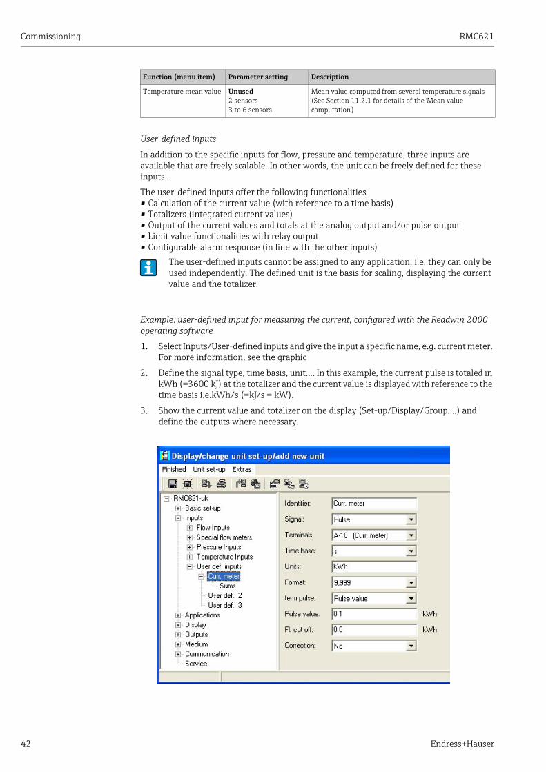
User-defined inputs
In addition to the specific inputs for flow, pressure and temperature, three inputs are available that are freely scalable. In other words, the unit can be freely defined for these inputs.
The user-defined inputs offer the following functionalities• Calculation of the current value (with reference to a time basis)• Totalizers (integrated current values)• Output of the current values and totals at the analog output and/or pulse output• Limit value functionalities with relay output• Configurable alarm response (in line with the other inputs)
Example: user-defined input for measuring the current, configured with the Readwin 2000 operating software
1. Select Inputs/User-defined inputs and give the input a specific name, e.g. current meter. For more information, see the graphic
2. Define the signal type, time basis, unit.... In this example, the current pulse is totaled in kWh (=3600 kJ) at the totalizer and the current value is displayed with reference to the time basis i.e.kWh/s (=kJ/s = kW).
3. Show the current value and totalizer on the display (Set-up/Display/Group....) and define the outputs where necessary.
Temperature mean value Unused2 sensors3 to 6 sensors
Mean value computed from several temperature signals(See Section 11.2.1 for details of the 'Mean value computation')
The user-defined inputs cannot be assigned to any application, i.e. they can only be used independently. The defined unit is the basis for scaling, displaying the current value and the totalizer.
Function (menu item) Parameter setting Description

RMC621 Commissioning
Endress+Hauser 43
Setup → Applications
Energy Manager applications:
• Gas:Norm volume - mass - heating value
• Steam:Mass - heat quantity - net heat quantity - heat difference
• Liquids:Heat quantity - heat difference - heating value
• Water:Heat quantity - heat difference
Up to three different applications can be calculated simultaneously. The configuration of an application is possible without restricting the applications available up to now in the operating status. Please note that when you have successfully configured a new application or changed the settings of an already existing application, the data are not accepted until the user enables the application at the end (question before exiting the setup).
Function (menu item) Parameter setting Description
Identifier Application 1-3 Name of the configured application, e.g. ’boiler room 1’.
Media
Gas Norm volume/massN.vol/mass/heat value
Select the desired application (depending on the type of media). If an application in operation should be switched off, choose ’Select’ here.
Liquids Heat diff.Heating val.
Water/steam Steam mass/heatNet steamS-heat diffWater heat quantityWater-heat diff
Medium SelectArgonMethaneAcetylene...
Select your medium8 gases (argon, methane, acetylene, oxygen, nitrogen, ammonia, hydrogen, natural gas and 2 liquids (butane, propane) can be selected (stored). Other media can be defined under "Setup → Medium". See ’Setup → Medium’
Flow SelectFlow 1-3
Assign a flow sensor to your application. Only the sensors that were configured previously (see ’Setup: Inputs - Flow inputs’) can be selected here.
Pressure SelectPressure 1-3
Assign the pressure sensor. Only the sensors that were configured previously (see ’Setup: Inputs - Pressure inputs’) can be selected here.
Temperature SelectTemperature 1-6
Assign the temperature sensor. Only the sensors that were configured previously (see ’Setup: Inputs - Temperature inputs’) can be selected here.Not for differential applications.
Reference value TemperaturePressureDensityz-factorHeating val*Gravity** Only for AGA8 or SGERG
Data in the normal gas state: these values are reference values for calculating the gas norm volume. 0 °C (32 °F) and 1.013 bar (14.69 psi) are set as standard.If you change the standard settings, adjust the density and z-factor if necessary!
Equation NX 19SGERG 88 (optional)AGA 8 (optional)
Equation standard for calculating the norm volume for natural gas.It can only be selected if natural gas is the medium!

Commissioning RMC621
44 Endress+Hauser
Mole content N2CO2H2 - only for AGA 8 and SGERG 88
Gas content in Mol-%.Temp. - 40 to 200 °C (-40 to 392 °F), pressure < 345 bar (5003 psi)Mol-% CO2: 0 to 15 %Mol-% N2: 0 to 15 %Mol-% H2: 0 to 15 %Only for natural gas applications.
Steam type Superheated steamSaturated steam
Sets the type of steam.Only for steam applications.
Input param. Q + TQ + P
Input parameters for saturated steam applications.Q + T: flow and temperatureQ + P: flow and pressureOnly two input variables are required to measure saturated steam. The missing variable is determined by the computer with the saturated steam curve stored (only for ’Saturated steam’ steam type).The input parameters flow, pressure and temperature are required for measuring superheated steam.Only for saturated steam applications.
Op. mode HeatingCooling Bidirectional
HeatingSteam generation
Setting as to whether your application absorbs energy (cooling) or gives off energy (heating). Bidirectional operation describes a circuit which is used for heating and for cooling.This can only be selected for the "Water heat difference" or "Liquid heat difference" application.Setting as to whether steam is used for heating purposes or whether steam is generated from water.This can only be selected for the "Steam-heat difference" application.
Flow direct. ConstantChanging
Information on the direction of flow in the circuit with bidirectional operation.Only for the Bidirectional operating mode.
Dir. signal Terminals Terminal for connecting the direction signal output of the flow transmitter.Only for the Bidirectional, Changing flow direction operating mode.
Flow SelectFlow 1-3
Assign a flow sensor to your application. Only the sensors that were configured previously (see ’Setup: Inputs - Flow inputs’) can be selected here.
Inst. point WarmCold
Set the 'thermal’ installation point at which the flow sensor is located in your application (only active for water/heat difference or liquid heat difference).The installation point is specified as follows for steam/heat difference:Heating: warm (i.e. steam flow)Steam generation: cold (i.e. water flow)In the event of bidirectional operation, make the settings as per the heating operating mode.
Mean pres. 10.0 bar Indicates the average process pressure (absolute) in the heating circuit.Only for water applications.
Temperaturecold
SelectTemperature 1-6
Assign the sensor which records the lower temperature in your application. Only the sensors that were configured previously (see ’Setup: Inputs - Temperature inputs’) can be selected here.Only for heat diff. applications.
TemperatureWarm
UnusedTemperature 1-6
Assign the sensor which records the higher temperature in your application. Only the sensors that were configured previously (see ’Setup: Inputs - Temperature inputs’) can be selected here.Only for heat diff. applications.
Function (menu item) Parameter setting Description
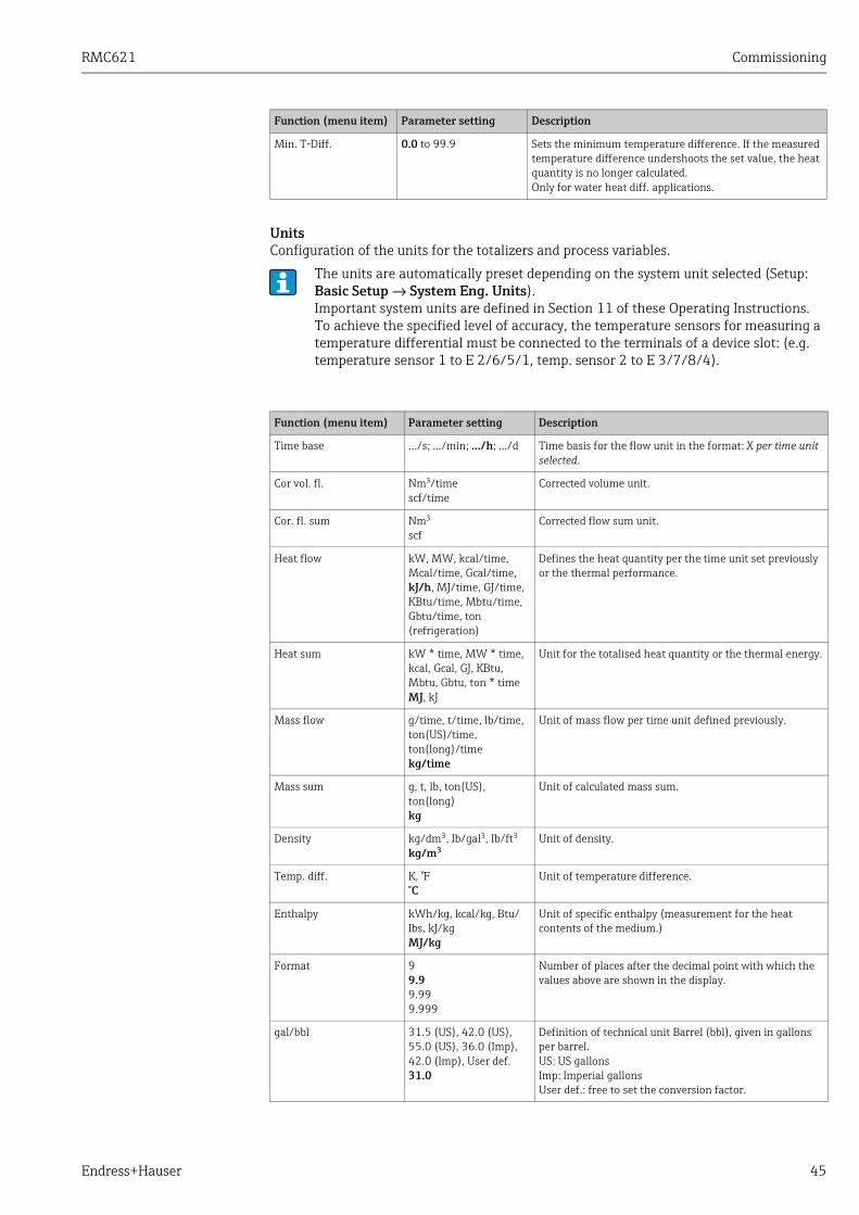
RMC621 Commissioning
Endress+Hauser 45
UnitsConfiguration of the units for the totalizers and process variables.
Min. T-Diff. 0.0 to 99.9 Sets the minimum temperature difference. If the measured temperature difference undershoots the set value, the heat quantity is no longer calculated.Only for water heat diff. applications.
The units are automatically preset depending on the system unit selected (Setup: Basic Setup → System Eng. Units).Important system units are defined in Section 11 of these Operating Instructions.To achieve the specified level of accuracy, the temperature sensors for measuring a temperature differential must be connected to the terminals of a device slot: (e.g. temperature sensor 1 to E 2/6/5/1, temp. sensor 2 to E 3/7/8/4).
Function (menu item) Parameter setting Description
Time base .../s; .../min; .../h; .../d Time basis for the flow unit in the format: X per time unit selected.
Cor vol. fl. Nm3/timescf/time
Corrected volume unit.
Cor. fl. sum Nm3
scfCorrected flow sum unit.
Heat flow kW, MW, kcal/time, Mcal/time, Gcal/time, kJ/h, MJ/time, GJ/time, KBtu/time, Mbtu/time, Gbtu/time, ton (refrigeration)
Defines the heat quantity per the time unit set previously or the thermal performance.
Heat sum kW * time, MW * time, kcal, Gcal, GJ, KBtu, Mbtu, Gbtu, ton * timeMJ, kJ
Unit for the totalised heat quantity or the thermal energy.
Mass flow g/time, t/time, lb/time, ton(US)/time, ton(long)/timekg/time
Unit of mass flow per time unit defined previously.
Mass sum g, t, lb, ton(US), ton(long)kg
Unit of calculated mass sum.
Density kg/dm3, Ib/gal3, Ib/ft3
kg/m3Unit of density.
Temp. diff. K, °F°C
Unit of temperature difference.
Enthalpy kWh/kg, kcal/kg, Btu/Ibs, kJ/kgMJ/kg
Unit of specific enthalpy (measurement for the heat contents of the medium.)
Format 99.99.999.999
Number of places after the decimal point with which the values above are shown in the display.
gal/bbl 31.5 (US), 42.0 (US), 55.0 (US), 36.0 (Imp), 42.0 (Imp), User def.31.0
Definition of technical unit Barrel (bbl), given in gallons per barrel.US: US gallonsImp: Imperial gallonsUser def.: free to set the conversion factor.
Function (menu item) Parameter setting Description
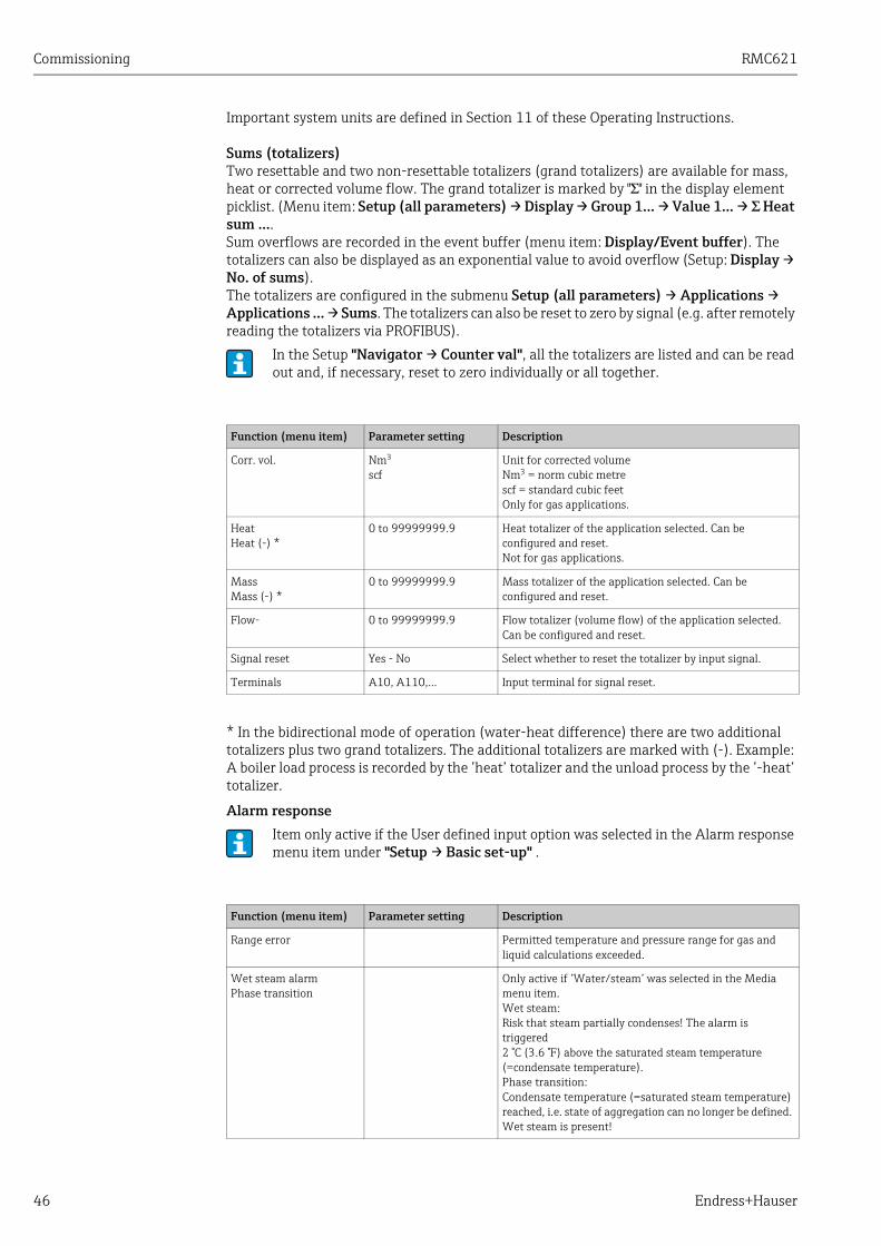
Commissioning RMC621
46 Endress+Hauser
Important system units are defined in Section 11 of these Operating Instructions.
Sums (totalizers)Two resettable and two non-resettable totalizers (grand totalizers) are available for mass, heat or corrected volume flow. The grand totalizer is marked by "Σ" in the display element picklist. (Menu item: Setup (all parameters) → Display → Group 1... → Value 1... → Σ Heat sum ....Sum overflows are recorded in the event buffer (menu item: Display/Event buffer). The totalizers can also be displayed as an exponential value to avoid overflow (Setup: Display → No. of sums).The totalizers are configured in the submenu Setup (all parameters) → Applications → Applications ... → Sums. The totalizers can also be reset to zero by signal (e.g. after remotely reading the totalizers via PROFIBUS).
* In the bidirectional mode of operation (water-heat difference) there are two additional totalizers plus two grand totalizers. The additional totalizers are marked with (-). Example: A boiler load process is recorded by the ’heat’ totalizer and the unload process by the ’-heat’ totalizer.
Alarm response
In the Setup "Navigator → Counter val", all the totalizers are listed and can be read out and, if necessary, reset to zero individually or all together.
Function (menu item) Parameter setting Description
Corr. vol. Nm3
scfUnit for corrected volumeNm3 = norm cubic metrescf = standard cubic feetOnly for gas applications.
HeatHeat (-) *
0 to 99999999.9 Heat totalizer of the application selected. Can be configured and reset.Not for gas applications.
MassMass (-) *
0 to 99999999.9 Mass totalizer of the application selected. Can be configured and reset.
Flow- 0 to 99999999.9 Flow totalizer (volume flow) of the application selected. Can be configured and reset.
Signal reset Yes - No Select whether to reset the totalizer by input signal.
Terminals A10, A110,... Input terminal for signal reset.
Item only active if the User defined input option was selected in the Alarm response menu item under "Setup → Basic set-up" .
Function (menu item) Parameter setting Description
Range error Permitted temperature and pressure range for gas and liquid calculations exceeded.
Wet steam alarmPhase transition
Only active if ’Water/steam’ was selected in the Media menu item.Wet steam: Risk that steam partially condenses! The alarm is triggered 2 °C (3.6 °F) above the saturated steam temperature (=condensate temperature).Phase transition:Condensate temperature (=saturated steam temperature) reached, i.e. state of aggregation can no longer be defined. Wet steam is present!

RMC621 Commissioning
Endress+Hauser 47
Setup → Display
The device display can be freely configured. Up to six groups, each with 1 to 8 freely definable process values, can be displayed individually or alternately. For each application, the most important values are automatically shown in two windows (groups) in the display: this does not apply if the display groups have already been defined. The way the process values are displayed depend on the number of values in a group.
Alarm type FaultHint
Fault: totalizer stop, colour change (red) and message in plain text.Hint: totalizer unaffected, colour change and message display can be configured.
Colour change YesNo
Select whether the alarm should be signalled by a colour change from blue to red.Only active if the ’Hint’ alarm type has been selected.
Fault text Display+acknowledgeDo not display
Select whether an alarm message should appear to describe the fault when a fault occurs. This is cleared (acknowledged) by pressing a key.Only active if the ’Hint’ alarm type has been selected.
Function (menu item) Parameter setting Description
If displaying one to three values in a group, all values with the name of the application and identifier (e.g. heat totalizer) and the related physical unit are displayed.As of four values, only the values and the physical unit are displayed.
In Setup "Display", the display functionality is configured. In "Navigator", then select which group(s) appear(s) with process values on the display.
Function (menu item) Parameter setting Description
Group 1 to 6Identifier
A name (max. 12 characters) can be given to the groups for a better overview.
Display mask 1 value to 8 valuesSelect
Here, set the number of process values which should be displayed beside one another in a window (as a group). The way the value is displayed depends on the number of selected values. The more values in a group, the smaller the display.
Value type Inputs, process values, counter, totalizer, miscellaneous
The display values can be selected from 4 categories (types).
Value 1 to 8 Select Selects which process values should be displayed.
Scrolling display Alternating display of individual groups on the display.
Swit. time 0 to 990
Seconds until the next group is displayed.
Group X YesNo
Select the groups that should be displayed alternately.The alternating display is activated in the "Navigator" / " Display" (see 6.3.1).
Display
OIML YesNo
Selects whether the counter readings should be displayed as per the OIML standard.

Commissioning RMC621
48 Endress+Hauser
Setup → Outputs
Analog outputs
Please note that these outputs can be used as both analog and pulse outputs; the desired signal type can be selected for each setting. Depending on the version (extension cards), 2 to 8 outputs are available.
Pulse outputs
The pulse output function can be configured with active, passive output or relay. Depending on the version, 2 to 8 pulse outputs are available.
No. of sums Counter modeExponential
Sum displayCounter mode: sums are displayed with max. 10 positions up to overflow.Exponential: exponential display is used for large values.
Contrast 2 to 6346
For configuring the display contrast. This setting has an immediate affect. The contrast value is not saved until the setup is exited.
Function (menu item) Parameter setting Description
Identifier Anal. outp. 1 to 8 An identifier can be given to the analog output in question for a better overview (max. 12 characters).
Terminals B-131, B-133C-131, C-133D-131, D-133E-131, E-133None
Defines the terminal at which the analog signal should be output.
Sig. source Density 1Enthalpy 1Flow 1Mass flow 1Pressure 1Temperature 1Heat flow 1Select
Setting as to which calculated or measured variable should be output at the analog output. The number of signal sources depends on the number of configured applications and inputs.
Curr. range 4 to 20 mA, 0 to 20 mA Specifies the mode of operation of the analog output.
Start Value -999999 to 9999990.0
Smallest output value of the analog output.
End Value -999999 to 999999100
Largest output value of the analog output.
Time const. (signal damping)
0 to 99 s0 s
Time constant of the first order low pass for the input signal. This is used to prevent large fluctuations in the output signal (can only be selected for the signal type 0/4 and 20 mA).
Fault cond. action MinimumMaximumValueLast value
Defines the behaviour of the output in the event of a fault, e.g. if a sensor in the measurement fails.
Value -999999 to 9999990.0
Fixed value which should be output at the analog output in the event of a fault.Only for the Fault cond. action setting; value can be selected.
Simulation 0 - 3.6 - 4 - 10 - 12 - 20 - 21Off
The function of the current output is simulated. Simulation is active if the setting is not ’off’. Simulation ends as soon as you leave this item.
Function (menu item) Parameter setting Description

RMC621 Commissioning
Endress+Hauser 49
Function (menu item) Parameter setting Description
Identifier Pulse 1 to 8 An identifier can be assigned to the pulse output in question for a better overview (max. 12 characters).
Signal ActivePassiveRelaySelect
Assign the pulse output.Active: Active voltage pulses are output. Power is supplied from the device.Passive: Passive open collectors are available in this operating mode. Power must be supplied externally.Relay: The pulses are output on a relay. (The frequency is max. 5Hz)"Passive" can only be selected when extension cards are used.
Terminals B-131, B-133, C-131, C-133, D-131, D-133, E-131, E-133B-135, B-137, C-135, C-137, D-135, D-137A-52, B-142, B-152,C-142, C-152, D-142, D-152None
Defines the terminal at which pulses should be output.
Sig. source Heat sum 1, Heat sum 2, Flow sum 1, Flow sum 2, etc.Select
Setting as to which variable should be output at the pulse output.
Pulse
Type NegativePositive
Makes it possible to output pulses in a positive or negative direction (e.g. for external electronic totalizers):
• ACTIVE: the device-internal power supply is used (+24 V)
• PASSIVE: external power supply necessary• POSITIVE: quiescent level at 0 V ("active-high")• NEGATIVE: quiescent level at 24 V ("active-low") or
external power supply
PASSIVE-NEGATIVE
ACTIVE-NEGATIVE
ACTIVE-POSITIVE
PASSIVE-POSITIVE
ACTIVE
Internal
power supply
24 V DC
Push-
Pull
For continuous currents up to 15 mA
12
12
13
13
Short-circuit
proof output
Short-circuit
proof output
Open
Collector
External
power supply
U = 30 V DCmax
PASSIVE
For continuous currents up to 25 mA
NEGATIVE pulses
POSITIVE pulses

Commissioning RMC621
50 Endress+Hauser
Relay/set point
Relays or passive digital outputs (open collector) are available in the relay for limit functions. Depending on the version, 1 to 13 limit values (set points) are available.
Unit g, kg, t for mass sum signal sourcekWh, MWh, MJ for heat sum signal sourcedm3 for flow signal source
Unit of the output pulse.Pulse unit depends on the signal source selected.
Unit value 0.001 to 10000.01.0
Setting as to which value a pulse corresponds to (unit/pulse).The max. possible output frequency is 50 Hz. The suitable pulse value can be determined as follows:
Width YesNo
The pulse width limits the max. possible output frequency of the pulse output.Standard = pulse width fixed, i.e. always 100 ms.User defined = pulse width can be freely configured.
Value 0.04 to 1000 ms Configuration of the pulse width suiting the external totalizer. The maximum permitted pulse width can be calculated as follows:
Simulation 0.0 Hz - 0.1 Hz - 1.0 Hz - 5.0 Hz - 10 Hz - 50 Hz - 100 Hz - 200 Hz - 500 Hz - 1000 Hz - 2000 HzOff
The function of the pulse output is simulated with this setting. Simulation is active if the setting is not "off". Simulation ends if you leave this item.
Function (menu item) Parameter setting Description
Identifier Set Point 1 to 13 An identifier can be assigned to the set point in question for a better overview (max. 12 characters).
Transmit By DisplayRelayDigitalSelect
Assigns where the set point is output (passive digital output only available with extension card).
Terminals A-52, B-142, B-152,C-142, C-152, D-142, D-152B-135, B-137, C-135, C-137, D-135, D-137None
Defines the terminal of the set point selected.Relay: terminals X-14X, X-15X
Digital: terminals X-13X
Function (menu item) Parameter setting Description
Pulse value Estimated max. flow (end value)Desired max. output frequency
2 x max. output frequency Pulse width

RMC621 Commissioning
Endress+Hauser 51
Op. Mode Max+Alarm, Grad.+Alarm, Alarm, Min, Max, Gradient, Wet Steam Alarm, Unit FailureMin+Alarm
Definition of the event which should activate the set point.
• Min+AlarmMinimum safety, event report when set point is undershot with simultaneous signal source monitoring to NAMUR NE43.
• Max+AlarmMaximum safety, event report when set point is overshot with simultaneous signal source monitoring to NAMUR NE43.
• Grad.+AlarmGradient analysis, event report when set signal change is overshot per time unit of the signal source with simultaneous signal source monitoring to NAMUR NE43.
• AlarmSignal source monitoring to NAMUR NE43, no set point function.
• MinEvent report when set point is undershot without taking NAMUR NE43 into consideration.
• MaxEvent report when set point is overshot without taking NAMUR NE43 into consideration.
• GradientGradient analysis, event report when set signal change is overshot per time unit of the signal source without taking NAMUR NE43 into account.
• Wet Steam AlarmRelay (output) switches in the event of a wet steam alarm (2 C above saturated steam temperature).
• Unit failureRelay (output) switches when a device fault is present (collective alarm for all faults).
Sig. Source Flow 1, Heat Flow 1, Mass Sum 1, Flow 2, etc.Select
Signal sources for the selected set point.The number of signal sources depends on the number of configured applications and inputs.
Swit. Point -99999 to 999990.0
Smallest output value of the analog output.
Hysteresis -99999 to 999990.0
Specify set point switch-back threshold to suppress set point bounce.
Time Delay 0 to 99 s0 s
Time span of limit value violation before it is displayed. Suppresses peaks in the sensor signal.
Gradient -Δx -19999 to 999990.0
Value of signal change for gradient analysis (inclination function).
Gradient -Δt 0 to 100 s0 s
Time interval for the signal change of the gradient analysis.
Gradient -reset value -19999 to 999990
Switch-back threshold for gradient analysis.
Limit On You can write a message for when the limit value (set point) is overshot. Depending on the setting, this appears in the event buffer and the display (see ’Lim. Display’)
Limit Off You can write a message for when the limit value (set point) is undershot. Depending on the setting, this appears in the event buffer and the display (see ’Lim. Display’)
Limit Dis. Disp.+Ackn.Not Display
Definition of the way of reporting the limit value.Not Display: Limit value violation or violated limit value undershooting is recorded in the event buffer.Disp.+Ackn.: Entered in the event buffer and shown on the display. The message does not disappear until it is acknowledged with a key.
Function (menu item) Parameter setting Description

Commissioning RMC621
52 Endress+Hauser
Setup → Medium
This option is used to describe a specific medium, e.g. if the required medium is not stored in the device.You require basic data on the characteristics of the medium for this. Based on this data, density, heat value and gas compressibility in operating mode are determined using tables and equations.
8 gases and 2 liquids are stored in the device with all data for compressibility, density, etc. (see ’Setup → Applications’). These media are not listed in the ’Medium’ menu.
Function (menu item) Parameter setting Description
Liquid 1 to 3Gas 1 to 3
Up to three liquids and three gases can be defined by entering various basic data. The media stored in the device are not affected by this.
Liquid
Identifier Medium identifier (max. 12 characters).
Ref. Temperature -9999.99 to +9999.992.0°C
Enter temperature at standard conditions (°C).
Density Calculation LinearTableAnalog Signal
Method of calculation for determining densityLinear:Calculate density using reference density, reference temperature and expansion coefficient (linear function).Table:Up to 10 points with value pairs temperature/density (interpolation).Analog input:Density measurement with sensor (input signal).
Ref. Density -9999.99 to +9999.990.0
Enter density at standard conditions (kg/m3).
Expansion +4.88000000e-5 Enter thermal expansion coefficient of liquid (for temperature compensation of volume).
Category Heat CarrierFuel
Select whether the medium is used as a heat carrier or fuel.
Sp. Heat Capacity ConstantTable
Specific heat capacity of the liquid (for calculation of the heat quantity).Item active if Heat Carrier was selected in ’Category’.
Heat Value -9999.99 to +9999.990.0
Enter heat value of medium (in kJ/Nm3). Heat value = energy released when liquid is burned.Item active if Fuel was selected in ’Category'.
Viscosity YesNo
Viscosity of medium. Only necessary if flow is measured using differential pressure method (see Setup ’Special flow meters’).
Viscosity Tab. PointsPoints
Value pair temperature/viscosity at 2 points. The viscosity at process conditions is calculated based on these values.
Density Calc. Analog Signal
Density input for direct measurement of operating density with a sensor.Item active if Analog Signal was selected in ’Density Calculation’.
Signal Select0 to 20 mA4 to 20 mA
Output signal type of density sensor.
Terminals NoneA-10; A-110
Defines the terminal for connecting the density sensor.
Start Value 0.0000 to 999999 Start value for density at 0 or 4 mA.
End Value 0.0000 to 999999 End value for density at 20 mA.
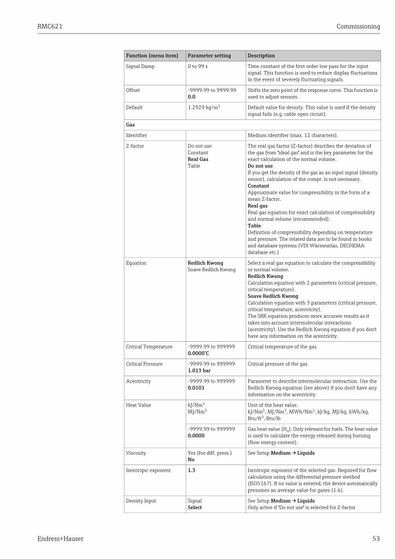
RMC621 Commissioning
Endress+Hauser 53
Signal Damp 0 to 99 s Time constant of the first order low pass for the input signal. This function is used to reduce display fluctuations in the event of severely fluctuating signals.
Offset -9999.99 to 9999.990.0
Shifts the zero point of the response curve. This function is used to adjust sensors.
Default 1.2929 kg/m3 Default value for density. This value is used if the density signal fails (e.g. cable open circuit).
Gas
Identifier Medium identifier (max. 12 characters).
Z-factor Do not useConstantReal GasTable
The real gas factor (Z-factor) describes the deviation of the gas from "ideal gas" and is the key parameter for the exact calculation of the normal volume.Do not useIf you get the density of the gas as an input signal (density sensor), calculation of the compr. is not necessary.ConstantApproximate value for compressibility in the form of a mean Z-factor.Real gasReal gas equation for exact calculation of compressibility and normal volume (recommended).TableDefinition of compressibility depending on temperature and pressure. The related data are to be found in books and database systems (VDI Wärmeatlas, DECHEMA database etc.)
Equation Redlich KwongSoave Redlich Kwong
Select a real gas equation to calculate the compressibility or normal volume.Redlich KwongCalculation equation with 2 parameters (critical pressure, critical temperature).Soave Redlich KwongCalculation equation with 3 parameters (critical pressure, critical temperature, acentricity).The SRK equation produces more accurate results as it takes into account intermolecular interactions (acentricity). Use the Redlich Kwong equation if you don't have any information on the acentricity.
Critical Temperature -9999.99 to 9999990.0000°C
Critical temperature of the gas.
Critical Pressure -9999.99 to 9999991.013 bar
Critical pressure of the gas.
Acentricity -9999.99 to 9999990.0101
Parameter to describe intermolecular interaction. Use the Redlich Kwong equation (see above) if you don't have any information on the acentricity.
Heat Value kJ/Nm3
MJ/Nm3Unit of the heat value.kJ/Nm3, MJ/Nm3, MWh/Nm3, kJ/kg, MJ/kg, kWh/kg, Btu/ft3, Btu/lb
-9999.99 to 9999990.0000
Gas heat value (Hu). Only relevant for fuels. The heat value is used to calculate the energy released during burning (flow energy content).
Viscosity Yes (for diff. press.)No
See Setup Medium → Liquids
Isentropic exponent 1.3 Isentropic exponent of the selected gas. Required for flow calculation using the differential pressure method (ISO5167). If no value is entered, the device automatically presumes an average value for gases (1.4).
Density Input SignalSelect
See Setup Medium → LiquidsOnly active if "Do not use" is selected for Z-factor
Function (menu item) Parameter setting Description

Commissioning RMC621
54 Endress+Hauser
Setup → Communication
An RS232 interface at the front and an RS485-interface at terminals 101/102 can be selected as standard. In addition, all process values can be read out via the PROFIBUS DP protocol.
Z-factor tableSelect a table type to describe the compressibility (Z-factor) of the gas.Tables can be entered directly in the device. However, it is considerably easier to do this using the free PC operating software. A matrix (table with 3 parameters) can only be entered using the PC operating software.
Tab. Type Temp const./Pressure variablePressure const./Temp. variableTemp variable/Pressure variable
Select the table type to describe the compressibility (Z-factor) of the gas.Temp const./Pressure variableValue pairs with temperature/Z-factor when pressure is constant.Pressure constant/Temp variableValue pairs with pressure/Z-factor when temperature is constant.Temp variable/pressure variable3-dimensional table (matrix) to describe the Z-factor depending on the temperature and pressure.
Temp. numberPressure number
01-15 Number of points to describe the compressibility.
Z-table Point 01-15 Table to describe the compressibility of the gas. Use point or discard it, i.e. remove it from table subsequently. Define the individual points by entering the pressure and temperature values (depending on the tab. type) and the corresponding Z-factor.
Z-matrix Temp 01-15, pressure 01-15, line1, line2, etc.
Option to view the 3-dimensional matrix.Temperatures specified in lines (x-axis), pressure defined in columns (y-value)Values for the matrix can only be entered using the free PC operating software.
Function (menu item) Parameter setting Description
Unit adr. 0 to 9900
Device address for communicating via the interface.
RS232
Baudrate 9600, 19200, 3840057600
Baudrate for the RS232 interface
RS485
Baudrate 9600, 19200, 3840057600
Baudrate for the RS485 interface
PROFIBUS-DP/ModBus/M-Bus (optional)
Number 0 to 480
Number of values which should be read out via the PROFIBUS-DP protocol (max. 49 values).
Adr. 0...4 e.g. density x Assigns the values to be read out to the addresses.
Adr. 5...9toAdr. 235...239
e.g. temp. diff. x 49 values can be read out via an address. Addresses in bytes (0…4, … 235…239) in numerical order.
Function (menu item) Parameter setting Description
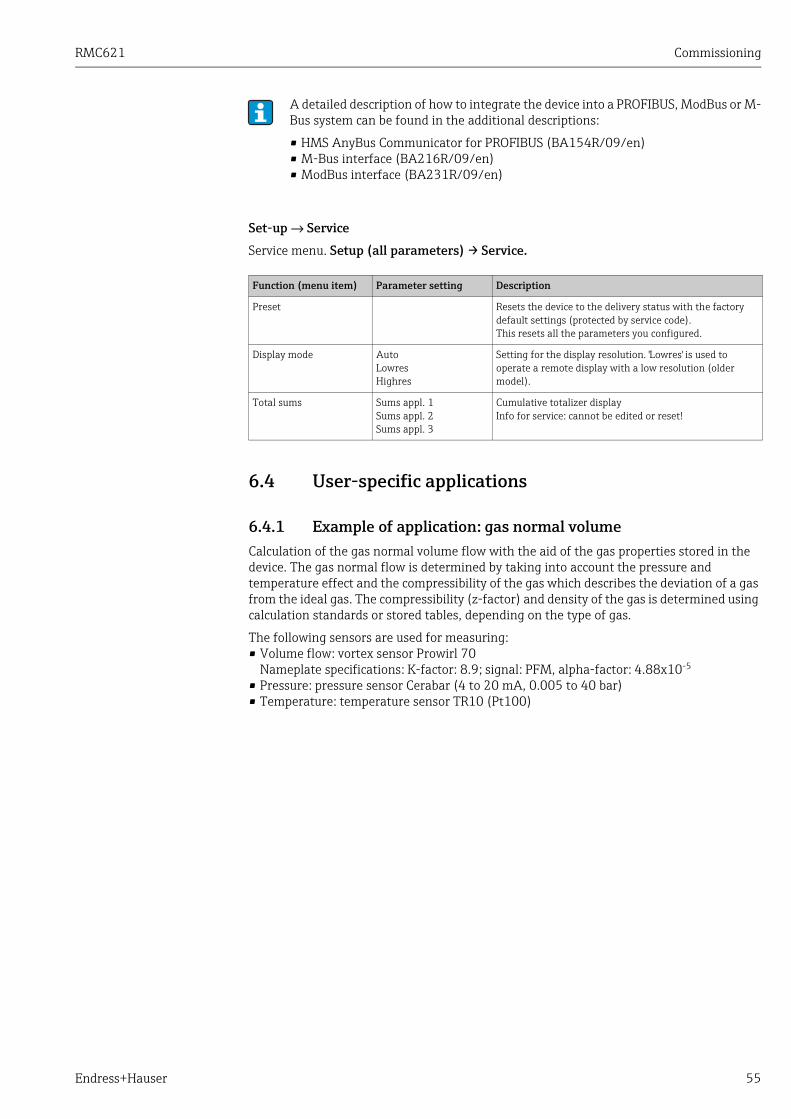
RMC621 Commissioning
Endress+Hauser 55
Set-up → Service
Service menu. Setup (all parameters) → Service.
6.4 User-specific applications
6.4.1 Example of application: gas normal volume Calculation of the gas normal volume flow with the aid of the gas properties stored in the device. The gas normal flow is determined by taking into account the pressure and temperature effect and the compressibility of the gas which describes the deviation of a gas from the ideal gas. The compressibility (z-factor) and density of the gas is determined using calculation standards or stored tables, depending on the type of gas.
The following sensors are used for measuring:• Volume flow: vortex sensor Prowirl 70
Nameplate specifications: K-factor: 8.9; signal: PFM, alpha-factor: 4.88x10⁻⁵
• Pressure: pressure sensor Cerabar (4 to 20 mA, 0.005 to 40 bar)• Temperature: temperature sensor TR10 (Pt100)
A detailed description of how to integrate the device into a PROFIBUS, ModBus or M-Bus system can be found in the additional descriptions:
• HMS AnyBus Communicator for PROFIBUS (BA154R/09/en)• M-Bus interface (BA216R/09/en)• ModBus interface (BA231R/09/en)
Function (menu item) Parameter setting Description
Preset Resets the device to the delivery status with the factory default settings (protected by service code).This resets all the parameters you configured.
Display mode AutoLowresHighres
Setting for the display resolution. 'Lowres' is used to operate a remote display with a low resolution (older model).
Total sums Sums appl. 1Sums appl. 2Sums appl. 3
Cumulative totalizer displayInfo for service: cannot be edited or reset!

Commissioning RMC621
56 Endress+Hauser
Exit setup by pressing ESC Z several times and confirming the changes.DisplayWhen you press any key, you can select a group with display values or display all groups with automatic alternating display (→ å 23). If a fault occurs, the display changes colour (blue/red). See Section 5.3 ’Error message display’ for information on how to eliminate the error.
1. Flow transmitter (Setup Inputs - Flow inputs)Flow 1DPT: volumetricSignal: PFM Terminals: select A10 and connect sensor to terminal A10(-)/82(+) (as passive signal)K-factor: 8.9Exp. coeff: 4.88x10⁻⁵
2. Pressure sensor (Setup Pressure):Pressure 1Signal: 4 to 20 mA, Terminals: select A110(+) and connect pressure transmitter to terminal A110(-)/A83(+)-Type: select absolute pressure measurement or relative pressure measurement Start value 0.005 bar,End value 40 bar,Default 25 bar (pressure the energy computer keeps working with if the sensor fails)
3. Temperature sensor (Setup Temperature):Temp. 1.1.Signal: Pt100.Sensor type: 3-wire or 4-wire.Select terminal E1/6 and connect Pt100 temperature sensor.Default (enter average operating temperature expected).(See graphics on left for operating example).
4. Configure application (Setup Applications):Applications (Applic. 1) Media: gas Medium: e.g. airGas appl.: norm volume/massAssign flow sensor, pressure sensor and temperature sensor for the gas measurement.Reference value: only set if normal conditions are not 0 °C (32 °F)/1.013 bar (14.69 psi).
5. Configure display (Setup Display), works automatically when commissioning (optional for application changes):Groups:Group 1: 3 value types and values (mass flow 1, pressure 1, temperature 1.1)Group 2: 1 value type and value (correct vol. flow 1)Scrolling display:Swit. time: 10 secondsGroup1: yesGroup2: yes
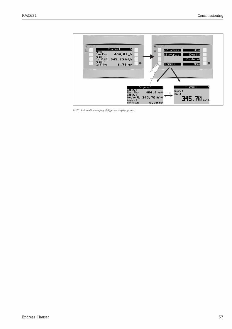
RMC621 Commissioning
Endress+Hauser 57
23: Automatic changing of different display groups

Maintenance RMC621
58 Endress+Hauser
7 MaintenanceNo special maintenance work is required for the device.
8 Accessories
Identifier Order code
RS232 interface cable 3.5 mm jack to connect to PC, with PC software RXU10-A1
Remote display for panel mounting 144 x 72 mm RMC621A-AA
Protective housing IP 66 for top-hat rail devices 52010132
PROFIBUS Interface Module HMS AnyBus Communicator for PROFIBUS RMC621A-P1
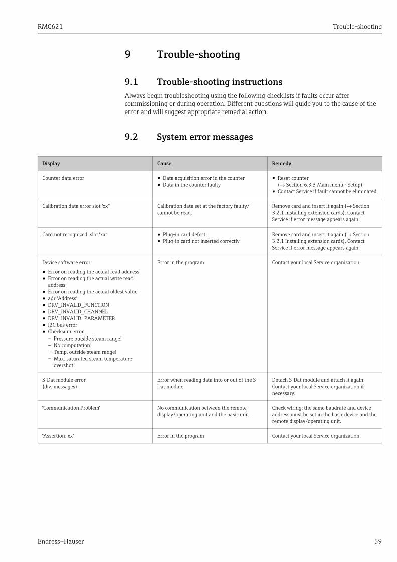
RMC621 Trouble-shooting
Endress+Hauser 59
9 Trouble-shooting
9.1 Trouble-shooting instructionsAlways begin troubleshooting using the following checklists if faults occur after commissioning or during operation. Different questions will guide you to the cause of the error and will suggest appropriate remedial action.
9.2 System error messages
Display Cause Remedy
Counter data error • Data acquisition error in the counter• Data in the counter faulty
• Reset counter(→ Section 6.3.3 Main menu - Setup)
• Contact Service if fault cannot be eliminated.
Calibration data error slot "xx“ Calibration data set at the factory faulty/cannot be read.
Remove card and insert it again (→ Section 3.2.1 Installing extension cards). Contact Service if error message appears again.
Card not recognized, slot "xx“ • Plug-in card defect• Plug-in card not inserted correctly
Remove card and insert it again (→ Section 3.2.1 Installing extension cards). Contact Service if error message appears again.
Device software error:
• Error on reading the actual read address• Error on reading the actual write read
address• Error on reading the actual oldest value• adr "Address"• DRV_INVALID_FUNCTION• DRV_INVALID_CHANNEL• DRV_INVALID_PARAMETER• I2C bus error• Checksum error
– Pressure outside steam range!– No computation!– Temp. outside steam range!– Max. saturated steam temperature
overshot!
Error in the program Contact your local Service organization.
S-Dat module error(div. messages)
Error when reading data into or out of the S-Dat module
Detach S-Dat module and attach it again. Contact your local Service organization if necessary.
"Communication Problem" No communication between the remote display/operating unit and the basic unit
Check wiring; the same baudrate and device address must be set in the basic device and the remote display/operating unit.
"Assertion: xx" Error in the program Contact your local Service organization.
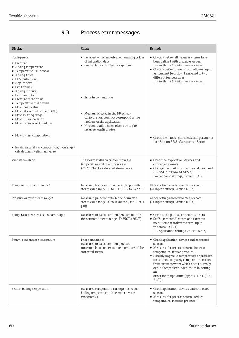
Trouble-shooting RMC621
60 Endress+Hauser
9.3 Process error messages
Display Cause Remedy
Config error:
• Pressure• Analog temperature• Temperature RTD sensor• Analog flow!• PFM pulse flow!• Applications!• Limit values!• Analog outputs! • Pulse outputs!• Pressure mean value• Temperature mean value• Flow mean value• Flow differential pressure (DP)• Flow splitting range• Flow DP: range error• Flow DP: incorrect medium
• Flow DP: no computation
• Invalid natural gas composition; natural gas calculation: invalid heat value
• Incorrect or incomplete programming or loss of calibration data
• Contradictory terminal assignment
• Error in computation
• Medium selected in the DP sensor configuration does not correspond to the medium of the application
• No computation takes place due to the incorrect configuration
• Check whether all necessary items have been defined with plausible values.(→ Section 6.3.3 Main menu - Setup)
• Check whether there is contradictory input assignment (e.g. flow 1 assigned to two different temperatures).(→ Section 6.3.3 Main menu - Setup)
• Check the natural gas calculation parameter (see Section 6.3.3 Main menu - Setup)
Wet steam alarm The steam status calculated from the temperature and pressure is near(2°C/3.6°F) the saturated steam curve
• Check the application, devices and connected sensors.
• Change the limit function if you do not need the “WET STEAM ALARM”.(→ Set point settings, Section 6.3.3)
Temp. outside steam range! Measured temperature outside the permitted steam value range. (0 to 800°C (32 to 1472°F))
Check settings and connected sensors.(→ Input settings, Section 6.3.3)
Pressure outside steam range! Measured pressure outside the permitted steam value range. (0 to 1000 bar (0 to 14504 psi))
Check settings and connected sensors.(→ Input settings, Section 6.3.3)
Temperature exceeds sat. steam range! Measured or calculated temperature outside the saturated steam range (T>350°C (662°F))
• Check settings and connected sensors.• Set "Superheated“ steam and carry out
measurement task with three input variables (Q, P, T).(→ Application settings, Section 6.3.3)
Steam: condensate temperature Phase transition!Measured or calculated temperature corresponds to condensate temperature of the saturated steam.
• Check application, devices and connected sensors.
• Measures for process control: increase temperature, reduce pressure.
• Possibly imprecise temperature or pressure measurement; purely computed transition from steam to water which does not really occur. Compensate inaccuracies by setting anoffset for temperature (approx. 1-3°C (1.8-5.4°F)).
Water: boiling temperature Measured temperature corresponds to the boiling temperature of the water (water evaporates!)
• Check application, devices and connected sensors.
• Measures for process control: reduce temperature, increase pressure.

RMC621 Trouble-shooting
Endress+Hauser 61
Signal range error "channel name" "signal name" Current output signal below 3.6 mA or above 21 mA.
• Check whether the current output is scaled correctly.
• Change the start and/or end value of the scaling
Cable open circuit: "channel name" "signal name)
Input current at current input smaller than 3.6 mA (with setting 4 to 20 mA) or larger than 21 mA.
• Incorrect wiring• Sensor not set to 4–20 mA range.• Sensor malfunction• Incorrectly configured end value for flow
transmitter
• Check sensor configuration. • Check function of the sensor.• Check end value of the connected flow
meter.• Check wiring.
Range error 3.6 mA < x < 3.8 mA (with setting 4 to 20 mA) or20.5 mA < x < 21 mA
• Incorrect wiring• Sensor not set to 4–20 mA range.• Sensor malfunction• Incorrectly configured end value for flow
transmitter
• Check sensor configuration.• Check function of the sensor.• Check measuring range/scaling of the
connected flow meter.• Check wiring.
Cable open circuit: "channel name" "signal name"
Resistance too high at PT100 input, e.g. due to short-circuit or cable break
• Incorrect wiring• PT100 sensor defect
• Check wiring.• Check function of the PT100 sensor.
Temp. differential range undercut Range of the set differential temperature overshot
Check current temperature values and set minimum temperature differential.
Limit value over/under cutLimit value ’number’ ok (blue)
• "Limit Value Identifier" < "Threshold Value" "Unit"
• "Limit Value Identifier" > "Threshold Value" "Unit"
• "Limit Value Identifier" > "Gradient" "Unit"• "Limit Value Identifier" < "Gradient" "Unit"• "User Defined Message"
Limit value undershot or overshot(→ Set point configuration, Section 6.3.3)
• Acknowledge alarm if the function “Set Point/Lim. Display/Disp.+Ackn.“ was configured(→ Set point configuration, Section 6.3.3).
• Check application if necessary.• Adjust set point if necessary.
• Temp. differential range undercut (red)• Temp. differential ok (blue)
Range of set differential temperature overshot. Check current temperature values and set minimum temperature differential.
W-heat diff: error: neg. temp. diff. The temperature assigned to the temperature sensor on the cold side is larger than the temperature on the warm side.
• Check whether the temperature sensors are correctly wired.
• Adjust process temperatures.
W-heat diff: error flow direction In bidirectional water-heat-diff. operation;If flow direction is configured as changing and the direction of flow does not suit the temperature values.
• Change flow direction signal at the direction terminal.
• Check the wiring of the temperature sensors.
• Pulse width must be between 0.04 and 1000 ms!
• Pulse width must be between 100 and 1000 ms!
Active/passive pulse output: configured pulse width not within valid range.
Change the pulse width to the value range given.
• Invalid value, too high• Invalid value, too low
• Fuel value entered too high• Fuel value entered too low
Fuel value must lie in the range between 19-48 MJ/Nm for correct use according to SGERG88/AGA8. Correct value to a value in this value range.
Entry must lie between 1 and 15! Incorrect number of points. Correct value to a value in this value range.
Display Cause Remedy
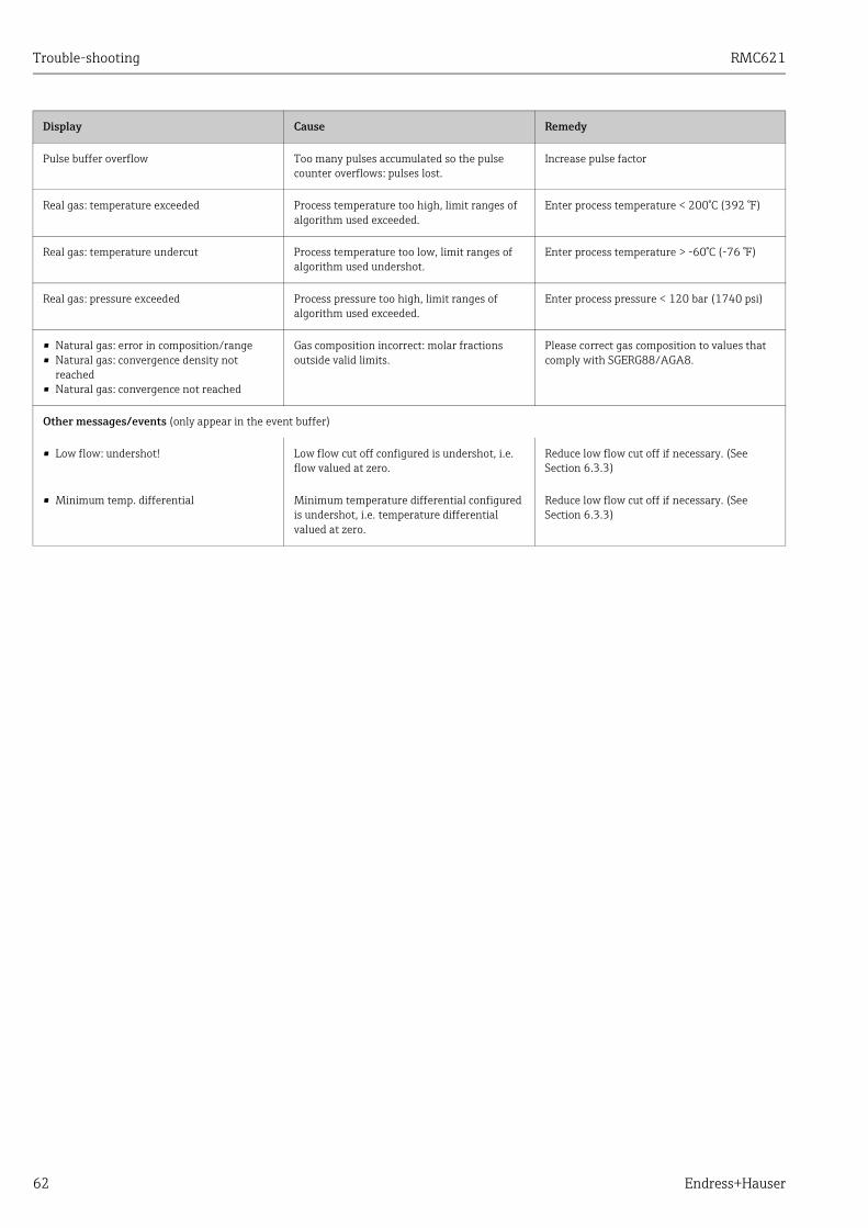
Trouble-shooting RMC621
62 Endress+Hauser
Pulse buffer overflow Too many pulses accumulated so the pulse counter overflows: pulses lost.
Increase pulse factor
Real gas: temperature exceeded Process temperature too high, limit ranges of algorithm used exceeded.
Enter process temperature < 200°C (392 °F)
Real gas: temperature undercut Process temperature too low, limit ranges of algorithm used undershot.
Enter process temperature > -60°C (-76 °F)
Real gas: pressure exceeded Process pressure too high, limit ranges of algorithm used exceeded.
Enter process pressure < 120 bar (1740 psi)
• Natural gas: error in composition/range• Natural gas: convergence density not
reached• Natural gas: convergence not reached
Gas composition incorrect: molar fractions outside valid limits.
Please correct gas composition to values that comply with SGERG88/AGA8.
Other messages/events (only appear in the event buffer)
• Low flow: undershot! Low flow cut off configured is undershot, i.e. flow valued at zero.
Reduce low flow cut off if necessary. (See Section 6.3.3)
• Minimum temp. differential Minimum temperature differential configured is undershot, i.e. temperature differential valued at zero.
Reduce low flow cut off if necessary. (See Section 6.3.3)
Display Cause Remedy

RMC621 Trouble-shooting
Endress+Hauser 63
9.4 Spare parts
24: Energy Manager spare parts
Item no.. Order number Spare part
1 RMC621X-HARMC621X-HB
Front cover, version without displayFront cover, version with display
2 RMC621X-HC Complete housing without frontincl. three blanking inserts and three PCB carriers
3 RMC621X-BA Bus board
4 RMC621X-NARMC621X-NBRMC621X-NCRMC621X-ND
Power unit 90 to 250 V ACPower unit 20 to 36 V DC // 20 to 28 V ACPower unit 90 to 250 V AC (ATEX version)Power unit 20 to 36 V DC // 20 to 28 V AC (ATEX version)
5 RMC621X-DARMC621X-DBRMC621X-DCRMC621X-DDRMC621X-DERMC621X-DFRMC621X-DGRMC621X-DH
Display incl. front boardFront board for version without displayDisplay + front cover, non-hazardous areaDisplay + front cover, neutral, non-hazardous areaDisplay cpl., hazardous areaFront cover, version without display, hazardous areaDisplay + front cover, hazardous areaDisplay + front cover, neutral, hazardous area
6 RMC621A-TA Temperature extension card (Pt100/Pt500/Pt1000), complete, incl. terminals and securing frames

Trouble-shooting RMC621
64 Endress+Hauser
6 RMC621A-TB Temperature extension card with intrinsically safe inputs in accordance with ATEX (Pt100/Pt500/Pt1000), complete, incl. terminals and securing frames
7 RMC621A-UA Universal extension card (PFM/pulse/analog/transmitter power supply unit), complete, incl. terminals and securing frames
7 RMC621A-UB Universal extension card with intrinsically safe inputs in accordance with ATEX (PFM/pulse/analog/transmitter power supply unit), complete, incl. terminals and securing frames
8 51000780 Mains terminal
9 51004062 Relay terminal/transmitter power supply unit
10 5100406351005957
Analog terminal 1 (PFM/pulse/analog/transmitter power supply unit)Analog terminal 1 (PFM/pulse/analog/transmitter power supply unit), Ex
11 5100406451005954
Analog terminal 2 (PFM/pulse/analog/transmitter power supply unit)Analog terminal 2 (PFM/pulse/analog/transmitter power supply unit), hazardous area
12 5100406751005955
Temperature terminal 1 (Pt100/Pt500/Pt1000)Temperature terminal 1 (Pt100/Pt500/Pt1000), hazardous area
13 5100406851005956
Temperature terminal 2 (Pt100/Pt500/Pt1000)Temperature terminal 2 (Pt100/Pt500/Pt1000), hazardous area
14 51004065 RS485 terminal
15 51004066 Output terminal (analog/pulse)
16 51004912 Relay terminal (extension card)
17 51004911 Extension card: open collector output terminal
18 51004066 Extension card: output terminal (4 to 20 mA/pulse)
19 5100490751005958
Extension card: input 1 terminal (Pt100/Pt500/Pt1000)Extension card: input 1 terminal, hazardous area (Pt100/Pt500/Pt1000)
20 5100490851005960
Extension card: input 2 terminal (Pt100/Pt500/Pt1000)Extension card: input 2 terminal, hazardous area (Pt100/Pt500/Pt1000)
21 5100491051005959
Extension card: input 1 terminal (4 to 20 mA/PFM/pulse/transmitter power supply)Extension card: input 1 terminal, hazardous area (4 to 20 mA/PFM/pulse/transmitter power supply)
22 5100490951005953
Extension card: input 2 terminal (4 to 20 mA/PFM/pulse/transmitter power supply unit)Extension card: input 2 terminal, hazardous area (4 to 20 mA/PFM/pulse/transmitter power supply)
23 RMC621C- CPU for energy computer (configuration, see below)
24 RMC621S- S-Dat module (configuration, see table on next page)
Item no.. Order number Spare part
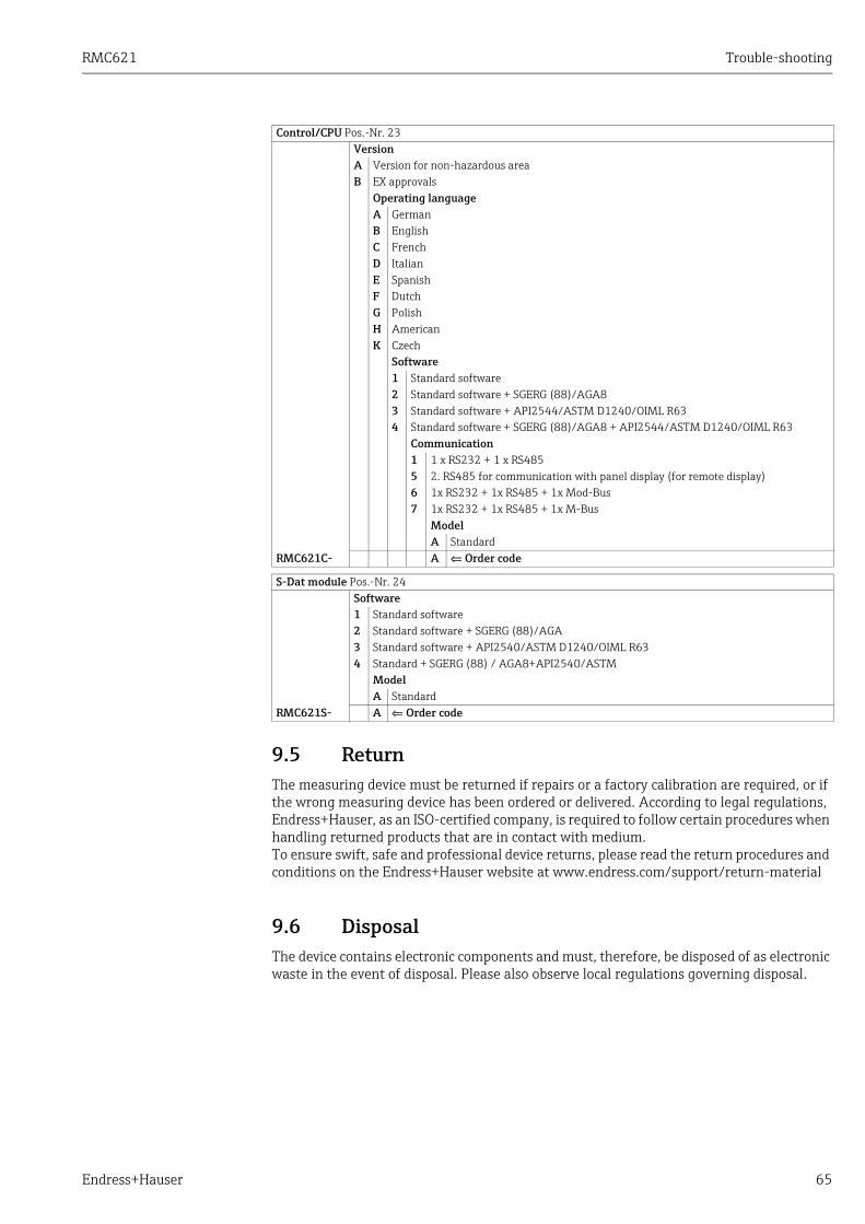
RMC621 Trouble-shooting
Endress+Hauser 65
9.5 ReturnThe measuring device must be returned if repairs or a factory calibration are required, or if the wrong measuring device has been ordered or delivered. According to legal regulations, Endress+Hauser, as an ISO-certified company, is required to follow certain procedures when handling returned products that are in contact with medium.To ensure swift, safe and professional device returns, please read the return procedures and conditions on the Endress+Hauser website at www.endress.com/support/return-material
9.6 DisposalThe device contains electronic components and must, therefore, be disposed of as electronic waste in the event of disposal. Please also observe local regulations governing disposal.
Control/CPU Pos.-Nr. 23VersionA Version for non-hazardous areaB EX approvals
Operating languageA GermanB EnglishC FrenchD ItalianE SpanishF DutchG PolishH AmericanK Czech
Software1 Standard software2 Standard software + SGERG (88)/AGA83 Standard software + API2544/ASTM D1240/OIML R634 Standard software + SGERG (88)/AGA8 + API2544/ASTM D1240/OIML R63
Communication1 1 x RS232 + 1 x RS4855 2. RS485 for communication with panel display (for remote display)6 1x RS232 + 1x RS485 + 1x Mod-Bus7 1x RS232 + 1x RS485 + 1x M-Bus
ModelA Standard
RMC621C- A ⇐ Order code
S-Dat module Pos.-Nr. 24Software1 Standard software2 Standard software + SGERG (88)/AGA3 Standard software + API2540/ASTM D1240/OIML R634 Standard + SGERG (88) / AGA8+API2540/ASTM
ModelA Standard
RMC621S- A ⇐ Order code
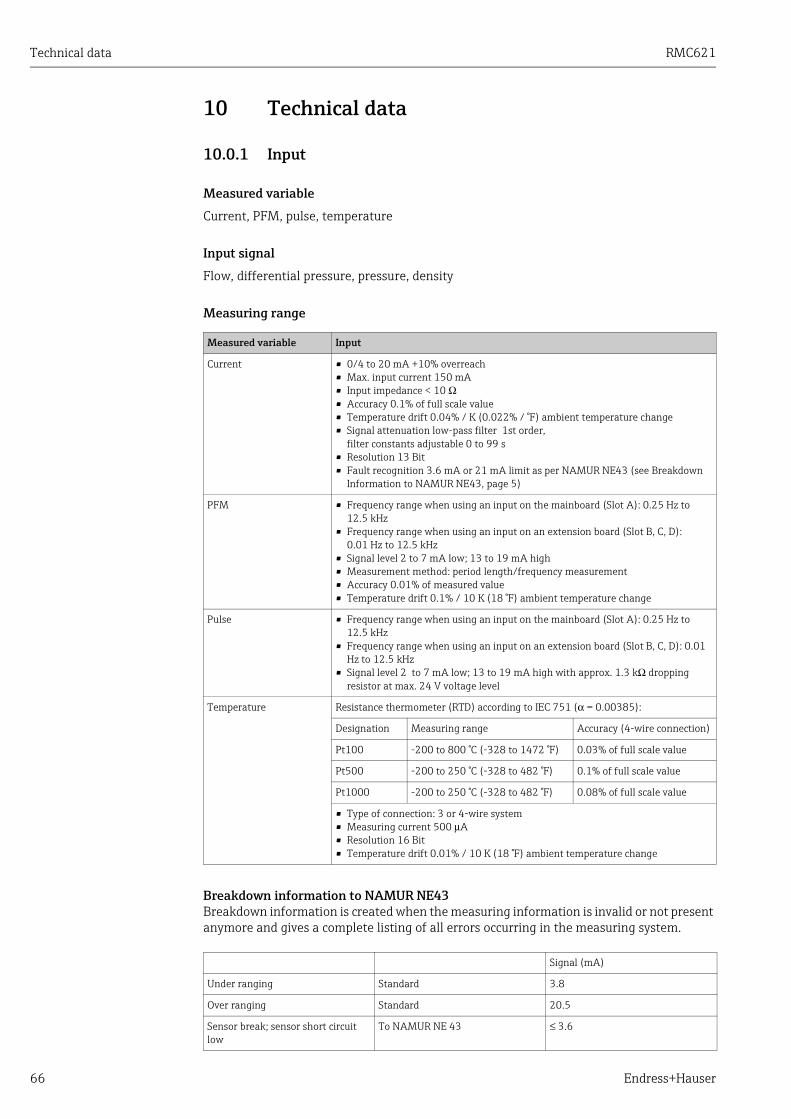
Technical data RMC621
66 Endress+Hauser
10 Technical data
10.0.1 Input
Measured variable
Current, PFM, pulse, temperature
Input signal
Flow, differential pressure, pressure, density
Measuring range
Breakdown information to NAMUR NE43Breakdown information is created when the measuring information is invalid or not present anymore and gives a complete listing of all errors occurring in the measuring system.
Measured variable Input
Current • 0/4 to 20 mA +10% overreach• Max. input current 150 mA• Input impedance < 10 Ω• Accuracy 0.1% of full scale value• Temperature drift 0.04% / K (0.022% / °F) ambient temperature change• Signal attenuation low-pass filter 1st order,
filter constants adjustable 0 to 99 s• Resolution 13 Bit• Fault recognition 3.6 mA or 21 mA limit as per NAMUR NE43 (see Breakdown
Information to NAMUR NE43, page 5)
PFM • Frequency range when using an input on the mainboard (Slot A): 0.25 Hz to 12.5 kHz
• Frequency range when using an input on an extension board (Slot B, C, D): 0.01 Hz to 12.5 kHz
• Signal level 2 to 7 mA low; 13 to 19 mA high• Measurement method: period length/frequency measurement• Accuracy 0.01% of measured value• Temperature drift 0.1% / 10 K (18 °F) ambient temperature change
Pulse • Frequency range when using an input on the mainboard (Slot A): 0.25 Hz to 12.5 kHz
• Frequency range when using an input on an extension board (Slot B, C, D): 0.01 Hz to 12.5 kHz
• Signal level 2 to 7 mA low; 13 to 19 mA high with approx. 1.3 kΩ dropping resistor at max. 24 V voltage level
Temperature Resistance thermometer (RTD) according to IEC 751 (α = 0.00385):
Designation Measuring range Accuracy (4-wire connection)
Pt100 -200 to 800 °C (-328 to 1472 °F) 0.03% of full scale value
Pt500 -200 to 250 °C (-328 to 482 °F) 0.1% of full scale value
Pt1000 -200 to 250 °C (-328 to 482 °F) 0.08% of full scale value
• Type of connection: 3 or 4-wire system• Measuring current 500 μA• Resolution 16 Bit• Temperature drift 0.01% / 10 K (18 °F) ambient temperature change
Signal (mA)
Under ranging Standard 3.8
Over ranging Standard 20.5
Sensor break; sensor short circuit low
To NAMUR NE 43 ≤ 3.6
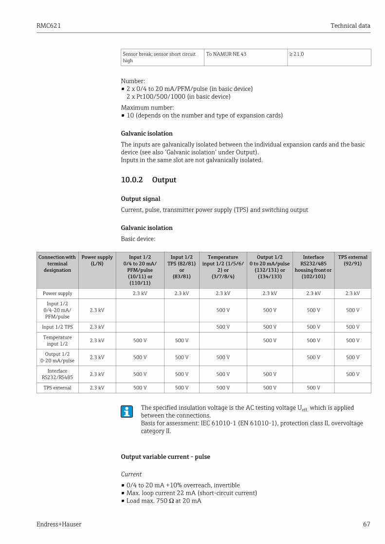
RMC621 Technical data
Endress+Hauser 67
Number:• 2 x 0/4 to 20 mA/PFM/pulse (in basic device)
2 x Pt100/500/1000 (in basic device)
Maximum number:• 10 (depends on the number and type of expansion cards)
Galvanic isolation
The inputs are galvanically isolated between the individual expansion cards and the basic device (see also ’Galvanic isolation’ under Output).Inputs in the same slot are not galvanically isolated.
10.0.2 Output
Output signal
Current, pulse, transmitter power supply (TPS) and switching output
Galvanic isolation
Basic device:
Output variable current - pulse
Current
• 0/4 to 20 mA +10% overreach, invertible• Max. loop current 22 mA (short-circuit current)• Load max. 750 Ω at 20 mA
Sensor break; sensor short circuit high
To NAMUR NE 43 ≥ 21.0
Connection with terminal
designation
Power supply (L/N)
Input 1/20/4 to 20 mA/
PFM/pulse (10/11) or (110/11)
Input 1/2 TPS (82/81)
or (83/81)
Temperature input 1/2 (1/5/6/
2) or (3/7/8/4)
Output 1/2 0 to 20 mA/pulse
(132/131) or (134/133)
Interface RS232/485
housing front or (102/101)
TPS external (92/91)
Power supply 2.3 kV 2.3 kV 2.3 kV 2.3 kV 2.3 kV 2.3 kV
Input 1/20/4-20 mA/PFM/pulse
2.3 kV 500 V 500 V 500 V 500 V
Input 1/2 TPS 2.3 kV 500 V 500 V 500 V 500 V
Temperature input 1/2
2.3 kV 500 V 500 V 500 V 500 V 500 V
Output 1/2 0-20 mA/pulse
2.3 kV 500 V 500 V 500 V 500 V 500 V
Interface RS232/RS485 2.3 kV 500 V 500 V 500 V 500 V 500 V
TPS external 2.3 kV 500 V 500 V 500 V 500 V 500 V
The specified insulation voltage is the AC testing voltage Ueff. which is applied between the connections.Basis for assessment: IEC 61010-1 (EN 61010-1), protection class II, overvoltage category II.

Technical data RMC621
68 Endress+Hauser
• Accuracy 0.1% of full scale value• Temperature drift: 0.1% / 10 K (0,056% / 10°F) ambient temperature change• Output Ripple < 10 mV at 500 Ω for frequencies < 50 kHz• Resolution 13 Bit• Error signals 3.6 mA or 21 mA limit adjustable as per NAMUR NE43 (see current inputs,
page 5)
Pulse
Basic device:• Frequency range to 12.5 kHz (18 kHz - version intrinsically safe)• Voltage level 0 to 1 V low, 24 V high ±15%• Load min. 1 kΩ• Pulse width 0.04 to 1000 ms
Expansion cards (digital passive, open collector):• Frequency range to 12.5 kHz (18 kHz - version intrinsically safe)• I max. = 200 mA• U max. = 24 V ± 15%• U low/max. = 1.3 V at 200 mA• Pulse width 0.04 to 1000 ms
Number
Number:• 2 x 0/4 to 20 mA/pulse (in basic device)
Max. number:• 8 x 0/4 to 20 mA/pulse (depends on the number of expansion cards)• 6 x digital passive (depends on the number of expansion cards)
Signal sources
All available multifunctional inputs (current, PFM or pulse inputs) and results can be freely allocated to the outputs.
Switching output
Function
Limit relay switches in these operating modes: minimum, maximum safety, gradient, alarm, saturated steam alarm, frequency/pulse, device error
Switch behavior
Binary, switches when the alarm value is reached (potential-free NO contact)
Relay switching capacity
Max. 250 V AC, 3 A / 30 V DC, 3 A
Switching frequency
Max. 5 Hz
Threshold
Programmable (wet steam alarm is preset at 2 °C (3.6 °F) at the factory)
When using relays on expansion cards, a mixture of low voltage and extra-low voltage is not permitted.

RMC621 Technical data
Endress+Hauser 69
Hysteresis
0 to 99%
Sig. Source
All available inputs and calculated variables can be allocated freely to the switching outputs.
Number
1 (in basic device)Max. number: 7 (depends on the number and type of expansion cards)
No of output states
100,000
Scan rate
500 ms
Transmitter power supply and external power supply
• Transmitter power supply unit, terminals 81/82 or 81/83 (optional universal expansion cards 181/182 or 181/183):Maximum supply voltage 24 V DC ±15%Impedance < 345 OhmMaximum output current 22 mA (for Uout > 16 V)
• Technical data Energy manager:HART®communication is not impairedNumber: 2 (in basic device)Maximum number: 8 (depending on the number and type of expansion cards).
• Additional power supply (e.g. external display), terminals 91/92:Supply voltage 24 V DC ± 5%Max. current 80 mA, short-circuit proofNumber 1Source resistance < 10 Ω
10.0.3 Power supply
Supply voltage
• Low voltage power unit: 90 to 250 V AC 50/60 Hz• Extra-low voltage power unit: 20 to 36 V DC or 20 to 28 V AC 50/60 Hz
Power consumption
8 to 26 VA (dependent on the expansion stage)
Connection data interface
RS232
– Connection: 3.5 mm (0.14 in) jack plug on front panel– Transmission protocol: ReadWin 2000– Transmission rate: max. 57,600 Baud
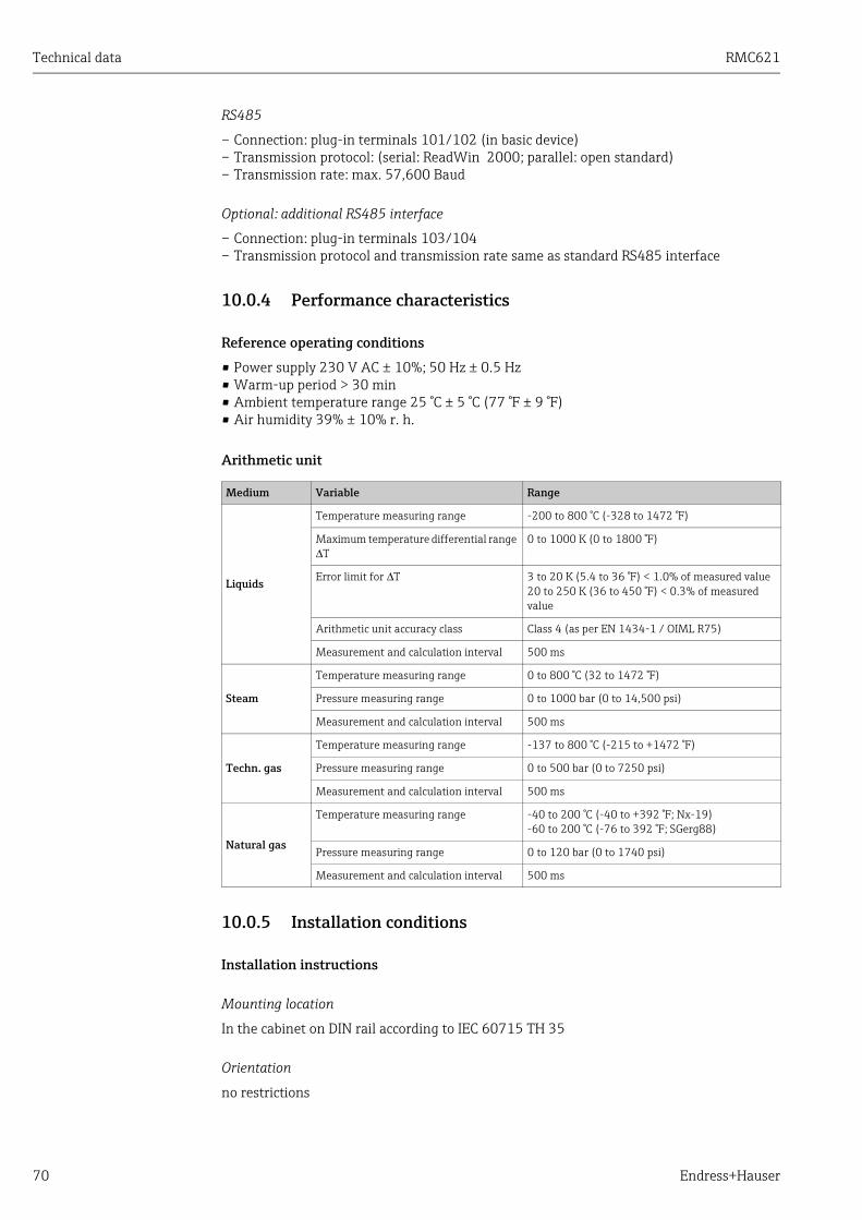
Technical data RMC621
70 Endress+Hauser
RS485
– Connection: plug-in terminals 101/102 (in basic device)– Transmission protocol: (serial: ReadWin 2000; parallel: open standard)– Transmission rate: max. 57,600 Baud
Optional: additional RS485 interface
– Connection: plug-in terminals 103/104– Transmission protocol and transmission rate same as standard RS485 interface
10.0.4 Performance characteristics
Reference operating conditions
• Power supply 230 V AC ± 10%; 50 Hz ± 0.5 Hz• Warm-up period > 30 min• Ambient temperature range 25 °C ± 5 °C (77 °F ± 9 °F)• Air humidity 39% ± 10% r. h.
Arithmetic unit
10.0.5 Installation conditions
Installation instructions
Mounting location
In the cabinet on DIN rail according to IEC 60715 TH 35
Orientation
no restrictions
Medium Variable Range
Liquids
Temperature measuring range -200 to 800 °C (-328 to 1472 °F)
Maximum temperature differential range ΔT
0 to 1000 K (0 to 1800 °F)
Error limit for ΔT 3 to 20 K (5.4 to 36 °F) < 1.0% of measured value20 to 250 K (36 to 450 °F) < 0.3% of measured value
Arithmetic unit accuracy class Class 4 (as per EN 1434-1 / OIML R75)
Measurement and calculation interval 500 ms
Steam
Temperature measuring range 0 to 800 °C (32 to 1472 °F)
Pressure measuring range 0 to 1000 bar (0 to 14,500 psi)
Measurement and calculation interval 500 ms
Techn. gas
Temperature measuring range -137 to 800 °C (-215 to +1472 °F)
Pressure measuring range 0 to 500 bar (0 to 7250 psi)
Measurement and calculation interval 500 ms
Natural gas
Temperature measuring range -40 to 200 °C (-40 to +392 °F; Nx-19)-60 to 200 °C (-76 to 392 °F; SGerg88)
Pressure measuring range 0 to 120 bar (0 to 1740 psi)
Measurement and calculation interval 500 ms

RMC621 Technical data
Endress+Hauser 71
10.0.6 Environment
Ambient temperature range
-20 to 60 °C (-4 to 140 °F)
Storage temperature
-30 to 70 °C (-22 to 158 °F)
Climate class
as per IEC 60 654-1 Class B2 / EN 1434 Class 'C'
Electr. safety
Ambient < 2000 m (6560 ft) height above sea level
Degree of protection
• Basic device: NEMA 1 (IP 20)• External display: NEMA 4X (IP 65)
Electromagnetic compatibility
Interference emission
IEC 61326 (EN 61326 Class A)
Interference immunity
– Power failure: 20 ms, no influence– Starting current limitation: Imax/In ≤ 50% (T50% ≤ 50 ms)– Electromagnetic fields: 10 V/m as per IEC 61000-4-3– Conducted HF: 0.15 to 80 MHz, 10 V as per IEC 61000-4-3– Electrostatic discharge: 6 kV contact, indirect as per IEC 61000-4-2– Burst (power supply): 2 kV as per IEC 61000-4-4– Burst (signal): 1 kV/2 kV as per IEC 61000-4-4– Surge (AC power supply): 1 kV/2 kV as per IEC 61000-4-5– Surge (DC power supply): 1 kV/2 kV as per IEC 61000-4-5– Surge (signal):500 V/1 kV as per IEC 61000-4-5

Technical data RMC621
72 Endress+Hauser
10.0.7 Mechanical construction
Design, dimensions
25: Housing for top-hat rail to IEC 60715; dimensions in mm (inch)
Weight
• Basic device: 500 g (1.1 lb) in maximum configuration with expansion cards• Remote control unit: 300 g (0.7 lb)
Material
Housing: polycarbonate plastic, UL 94V0
Terminals
Coded, pluggable screw terminals; Clamping area 1.5 mm2 (16 AWG) solid, 1.0 mm2 (18 AWG) flexible with wire end ferrule (applies to all connections).
10.0.8 Human interface
Display elements
• Display (optional):160 x 80 Dot-matrix LCD with blue background lightingColor changes to red in the event of an error (adjustable)
• LED status display:Operation: 1 x green (2 mm; 0.079 in)Fault message: 1 x red (2 mm; 0.079 in)
• External display and operating unit (optional or as accessory):A display and operating unit can also be connected to the energy manager in the panel mounted housing, dimensions (W = 144 x H = 72 x D = 43 mm (5.7 x 2.84 x 1.7 in)). The connection to the integrated RS485 interface is made using the connecting cable (l = 3 m / 10 ft), which is included in the accessories set. Parallel operation of the external display unit with a device-internal display in the RMC621 is possible.

RMC621 Technical data
Endress+Hauser 73
26: External display and operating unit for panel mounting (optional or available as accessory); dimensions in mm (inches)
Operating elements
Eight front-panel soft keys interact with the display (function of the keys is shown in the display).
Remote operation
RS232 interface (3.5 mm / 0.14 in) jack plug on front panel): configuration via PC with ReadWin 2000 PC operating software. RS485 interface.
Real time clock
‣ Deviation: 30 min per year‣ Power reserve: 14 days
Mathematical functions
Flow, differential pressure calculation: EN ISO 5167Continuous calculation of mass, standard volume, density, enthalpy, quantity of heat using stored algorithms and tables.
• Water / steam: IAWPS-IF97• Liquids: linear density function and tables for density and heat capacity
Mineral oil: API 2540, ASTM 1250, OIML R63• Technical gases: real gas equations (Soave Redlich Kwong), compressibility tables as well
as improved ideal gas equation• Natural gas: NX19, as option: SGERG88, AGA8 (gross-method)
Tables for density, heat value and compressibility can be edited freely or saved.
10.0.9 Certificates and approvals
CE mark
The measuring system meets the legal requirements of the EC Directives. Endress+Hauser confirms successful testing of the device by affixing to it the CE mark.
UL instrument safety
Instrument safety as per UL 3111-1 ‚
CSA GP
CSA General Purpose

Technical data RMC621
74 Endress+Hauser
Other standards and guidelines
• EN 60529:Degrees of protection through housing (IP code)
• EN 61010:Protection measures for electrical equipment for measurement, control, regulation and laboratory procedures
• EN 61326 (IEC 1326):Electromagnetic compatibility (EMC requirements)
• NAMUR NE21, NE43Association for Standards for Control and Regulation in the Chemical Industry
• IAWPS-IF 97Internationally applicable and recognized calculation standard (since 1997) for steam and water. Issued by the International Association for the Properties of Water and Steam (IAPWS).
• OIML R75International construction regulation and test specification for water Energy Managers of the Organisation Internationale de Métrologie Légale.
• EN 1434 1, 2, 5 and 6• EN ISO 5167
Flow measurement of fluids with throttle devices
10.0.10 Documentation• Product brochure for 'System components and Data Managers' (FA00016K/09)• Technical Information for 'Flow and Energy Manager RMC621' (TI00098R/09)

RMC621 Appendix
Endress+Hauser 75
11 Appendix
11.1 Definition of important system units
Volume
bbl 1 barrel, definition see ’Setup → Application’
gal 1 US gallon, corresponds to 3.7854 liters
igal Imperial gallon, corresponds to 4.5609 liters
l 1 liter = 1 dm3
hl 1 hectoliter = 100 liters
m3 corresponds to 1000 liters
ft3 corresponds to 28.37 liters
Norm volume
Nm3 Norm cubic meter (m3 at normal conditions)
Scf Standard cubic feet (ft3 at normal conditions)
Temperature
Conversion:
• 0°C = 273.15 K• °C = (°F - 32)/1.8
Pressure
Conversion:1 bar = 100 kPa = 100000 Pa = 0.001 mbar = 14.504 psi
Mass
ton (US) 1 US ton, corresponds to 2000 lbs (= 907.2 kg)
ton (long) 1 long ton, corresponds to 2240 lbs (= 1016 kg)
Performance (heat flow)
ton 1 ton (refrigeration) corresponds to 200 Btu/m
Btu/s 1 Btu/s corresponds to 1.055 kW
Energy (heat quantity)
therm 1 therm, corresponds to 100000 Btu
tonh 1 tonh, corresponds to 1200 Btu
Btu 1 Btu corresponds to 1.055 kJ
kWh 1 kWh corresponds to 3600 kJ which corresponds to 3412.14 Btu
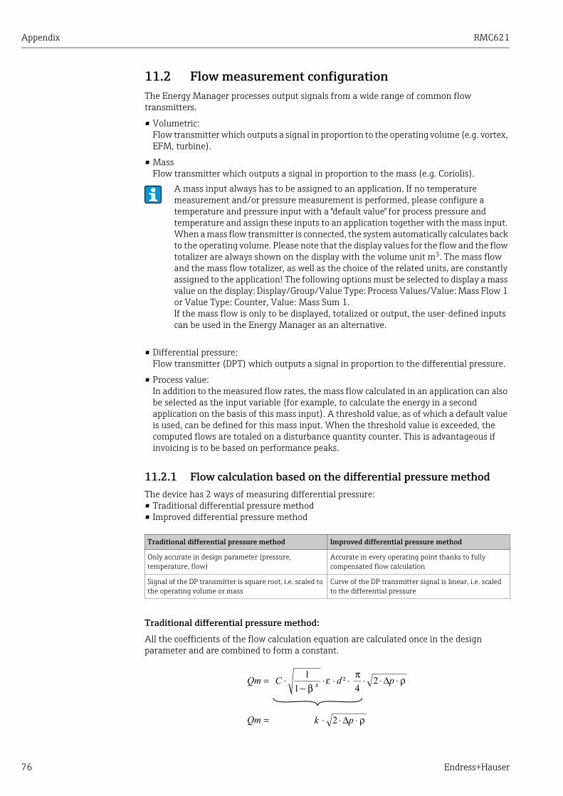
Appendix RMC621
76 Endress+Hauser
11.2 Flow measurement configurationThe Energy Manager processes output signals from a wide range of common flow transmitters.
• Volumetric:Flow transmitter which outputs a signal in proportion to the operating volume (e.g. vortex, EFM, turbine).
• MassFlow transmitter which outputs a signal in proportion to the mass (e.g. Coriolis).
• Differential pressure:Flow transmitter (DPT) which outputs a signal in proportion to the differential pressure.
• Process value:In addition to the measured flow rates, the mass flow calculated in an application can also be selected as the input variable (for example, to calculate the energy in a second application on the basis of this mass input). A threshold value, as of which a default value is used, can be defined for this mass input. When the threshold value is exceeded, the computed flows are totaled on a disturbance quantity counter. This is advantageous if invoicing is to be based on performance peaks.
11.2.1 Flow calculation based on the differential pressure methodThe device has 2 ways of measuring differential pressure:• Traditional differential pressure method• Improved differential pressure method
Traditional differential pressure method:
All the coefficients of the flow calculation equation are calculated once in the design parameter and are combined to form a constant.
A mass input always has to be assigned to an application. If no temperature measurement and/or pressure measurement is performed, please configure a temperature and pressure input with a "default value" for process pressure and temperature and assign these inputs to an application together with the mass input. When a mass flow transmitter is connected, the system automatically calculates back to the operating volume. Please note that the display values for the flow and the flow totalizer are always shown on the display with the volume unit m3. The mass flow and the mass flow totalizer, as well as the choice of the related units, are constantly assigned to the application! The following options must be selected to display a mass value on the display: Display/Group/Value Type: Process Values/Value: Mass Flow 1 or Value Type: Counter, Value: Mass Sum 1.If the mass flow is only to be displayed, totalized or output, the user-defined inputs can be used in the Energy Manager as an alternative.
Traditional differential pressure method Improved differential pressure method
Only accurate in design parameter (pressure, temperature, flow)
Accurate in every operating point thanks to fully compensated flow calculation
Signal of the DP transmitter is square root, i.e. scaled to the operating volume or mass
Curve of the DP transmitter signal is linear, i.e. scaled to the differential pressure

RMC621 Appendix
Endress+Hauser 77
Improved differential pressure method:
In contrast to the traditional method, the coefficients of the flow equation (flow coefficient, preacceleration factor, expansion number, density, etc.) are constantly recomputed as per ISO 5167. This has the advantage that the flow is determined exactly even under fluctuating process conditions, far beyond the design parameter (temperature and pressure in sizing parameter), thereby ensuring greater accuracy in flow measurement.
For this, the device just needs the following data:• Inner Dia.• Diameter ratio β (k-factor for Pitot tubes)
ƒ = correction factor (correction of measurement, e.g. to take pipe roughness into account)
Temperature effect on internal diameter and diameter ratio β
Please note: the pipe data often refer to the manufacturing temperature (approx. 20 C) or process temperature. The data are automatically converted to the operating temperature. For this purpose, just the expansion coefficient of the pipe material has to be entered.(Differential Pressure1 → Correction: Yes → Expansion Coefficient: ...)Temperature compensation can be omitted in the event of minor deviation (± 50 C) from the calibration temperature.
Pitot tubes
When using Pitot tubes, a correction factor has to be entered instead of the diameter ratio. This factor (resistance coefficient) is specified by the probe manufacturer (k-factor).It is absolutely imperative that this correction factor be entered! (See following example).
The flow is calculated as follows:
ƒ = correction factor (k-factor or value from the correction table)d = internal diameterΔP = differential pressureρ = density in operating status
Example:Flow measurement in a steam line with a Pitot tube
• Internal diameter: 350 mm• K-factor (correction factor for the resistance coefficient of the probe): 0.634• Working range ΔP: 0 - 51, 0 mbar (Q: 0-15000 m3/h)
Notes on the configuration:• Flow → Flow 1; Diff.pressure → Pitot; Signal → 4...20 mA; → Range start/range end (mbar);
Pipe data→ Inner dia. 350 mm; → Factor 0.634.

Appendix RMC621
78 Endress+Hauser
Flow measurement with V cone transmitter
The following data are needed when using V-cone flow transmitters:
• Inner Dia.• Geom. Ratio β• Flow coefficient c
The flow coefficient can be entered as a fixed value or in the form of a table depending on the Reynolds number. Please refer to the data sheet of the manufacturer for data regarding this. The flow is calculated from the input signals differential pressure, temperature and static pressure as per ISO 5167 (see Improved method). The temperature effect on the V-cone (Fa value) is calculated automatically when the thermal expansion coefficient of the V-cone is entered (see "Temperature effect on internal diameter and diameter ratio β" above).If the data available are insufficient, scale the DP transmitter to volume and use the flow input in Energy Manager.
General notes on differential pressure measurement
If all the data on the differential pressure measuring point are available (internal pipe diameter, β or k-factor), we recommend you use the improved method (fully compensated flow calculation).If the data required are not available, the output signal of the differential pressure transmitter is output scaled to volume or mass (see the following table). Please note that a signal scaled to mass can no longer be compensated. For this reason, scale the DP transmitter to operating volume if possible (mass: density in design parameter = operating volume). The mass flow is then calculated in the device based on the density in the operating status, depending on the temperature and pressure. This is partially compensated flow calculation, since the square root density is in the design parameter when measuring the operating volume.An example of a measurement setup can be found in the Appendix 'Applications: steam mass/quantity of heat'.
How should the Energy Manager and the sensor be configured?
Accuracy of air flow measurement with an orifice plate depending on the measurement methodExample:
• Orifice corner tap DP0 50: internal diameter 200 mm; β = 0.7• Flow operational range: 22.6 to 6785 m3/h (0 to 662.19 mbar)• Sizing parameter: 3 bar; 20°C; 3.57 kg/m3; 4000 m3/h• Process temperature: 30°C• Process pressure (true value): 2.5 bar• Differential pressure: 204.9 mbar
Sensor Type Unit
1. Traditional method
No data available on the pipe diameter and diameter ratio β (k-factor for Pitot tube).
a) (Default) Square root curve e.g. 0...1000 m3 (t) Flow input (operating volume or mass)Linear curve e.g. 0...1000 m3 (t)
b) Linear curve e.g. 0...2500 mbar Flow input (operating volume or mass)Curve square root, e.g. 0...1000 m3 (t)
2. Improved method
Pipe diameter and diameter ratio β (k-factor for Pitot tube) known.
a) (Default) Linear curve e.g. 0...2500 mbar Special flow (DP) e.g. orifice plateLinear curve e.g. 0...2500 mbar
b) Square root curve e.g. 0...1000 m3 (t) Special flow (DP) e.g. orifice plateCurve square law 0...2500 mbar

RMC621 Appendix
Endress+Hauser 79
• Reference operating conditions: 0 °C; 1.013 bar
a. Result when measuring based on the traditional differential pressure method:Operating volume: 4000 m3/h normal volume: 11041 Nm3/h (density: 3.57 kg/m3)
b. Result with improved, fully compensated differential pressure method (real flow):Operating volume: 4436 m3/h normal volume 9855 Nm3/h (density: 2.87 kg/m3)
The measured error for traditional flow measurement is approx. 10.9%. If the DPT is scaled to normal volume and both T and P are taken to be constant (i.e. no compensation possible), the total error is approx. 12%.
Splitting Range (measuring range extension)
The measuring range of a differential pressure transmitter is between 1:3 and 1:7. This function gives you the opportunity of extending the measuring range of the flow measurement to 1:20 and more by using up to three differential pressure transmitters per flow measuring point.
Notes on the configuration:
1. Select Flow/Splitting Range 1 (2, 3)
2. Define the signal and select the differential pressure transmitter (applies to all differential pressure transmitters!)
3. Select the terminals for the transmitters and define the measuring ranges.Range 1: transmitter with the smallest measuring rangeRange 2: transmitter with the next biggest measuring range etc.
4. Specify curve, units, format, sums, pipe data etc. (applies to all transmitters)
27: Splitting Range operation
Mean value computation
Mean value computation gives you the opportunity of measuring an input variable using several sensors at different points and then getting the mean value from them. This function helps if several measuring points are required in a system in order to determine the measured variable with sufficient accuracy. Example: use of several Pitot tubes to measure flow in pipes with insufficient inlet runs or a large cross section.
In the Splitting Range mode, it is compulsory to use differential pressure transmitters which output currents > 20 mA (< 4.0 mA) when the measuring range is overshot. The system automatically switches between the measuring ranges (switchover points 20.1 and 19.5 mA).If the input current of measuring range 1 reaches 20.1 mA, the system switches to measuring range 2. If the current value in range 2 drops below 19.5 mA, measuring range 1 is active again.

Appendix RMC621
80 Endress+Hauser
Mean value computation is available for the input variables pressure, temperature and special flow meters (differential pressure).
Correction tables
Flow transmitters return an output signal in proportion to the flow. The relationship between the output signal and the flow can be described in the curve. The flow cannot always be determined exactly by a curve in the entire measuring range of a transmitter, i.e. the flow transmitter shows a deviation from the ideal curve pattern. This deviation can be compensated for with the correction table.
The correction is different, depending on the type of flow transmitter:• Analog signal (volumetric, mass)
Table with up to 15 current/flow value pairs• Pulse signal (volumetric, mass)
Table with up to 15 value pairs (frequency/k-factor or frequency/pulse value, depending on the type of signal)
• Differential pressure square root/not square rootTable with up to 10 value pairs (flow/factor ƒ)
The points are automatically sorted by the device, i.e. you can define the points in any order.Make sure that the operating status is within the table limits since values outside the table range are determined by extrapolation. This can result in greater inaccuracies.

RMC621 Appendix
Endress+Hauser 81
11.3 Application sheets
11.3.1 Water/quantity of heat
Applications
Calculation of the quantity of heat in a flow of water. For example, determining the residual heat in the return pipe of a heat exchanger, etc.
Measured variables
Measuring the operating volume flow and temperature in a water pipe
Display/formula for calculation
G09-RMS621xx-15-10-xx-xx-005
28: Water/quantity of heat application
Input Param.
• Flow (q)• Temperature (T)
E: Quantity of heat T: Operating temperatureq: Volumetric p: Average operating pressureρ: Density h: Specific enthalpy of water (in relation to 0°C)
Another input variable is the operating pressure in the water pipe which is needed to accurately calculate the process variables and measuring range limits. The average operating pressure (p) is an input value (no input signal).Optionally, a pressure transmitter can be connected to display the pressure in the pipe. This pressure measurement does not have a direct effect on the calculation, however.

Appendix RMC621
82 Endress+Hauser
Calculated variables
Mass flow, heat flow, specific enthalpy (unit for the heat contents of water, in relation to 0°C), densityCalculation standard: IAPWS–IF97
Output variables/display at device
• Heat flow (performance), mass flow, flow (operating volume), temperature, specific enthalpy, density
• Totalizer: heat (energy), mass, volume, heat disturbance quantity, mass disturbance quantity.
Outputs
All the output variables can be output via analog and pulse outputs or the interfaces (e.g. bus). In addition, relay outputs for limit value violation are also available. The number of outputs depends on the version of the device.
Other functions
• Monitoring the state of aggregation. "Phase Transition" alarm when boiling temperature is reached
• Configurable alarm response, i.e. the function of the counters and outputs in the event of an error (e.g. cable open circuit, phase transition) can be individually defined.

RMC621 Appendix
Endress+Hauser 83
11.3.2 Water/heat difference(heating/cooling/bidirectional)
Applications
Calculation of the quantity of heat which is given off, or taken in, by a flow of water in a heat exchanger. Typical application for measuring energy in heating and cooling circuits. Similarly, bidirectional flows of energy can be measured depending on the temperature differential or flow direction (example: charging/discharging heat accumulators, geothermal reservoirs, etc.).
Measured variables
Measuring the operating volume flow (where necessary, also the flow direction) and the water temperature directly upstream and downstream from a heat exchanger (in feed or return pipe).
Display/formula for calculation
G09-RMS621xx-15-10-xx-xx-006
29: Water/heat differential application
Input Param.
• Temperature (T1) in feed pipe • Temperature (T2) in return pipe• Flow (q), where necessary with direction signal in the feed or return pipe
Heat emission (heating) Heat absorption (cooling)
E: Quantity of heat T2: Temperature in return pipe q: Volumetric p: Average operating pressureρ: Density h (T1): Specific enthalpy of water at temperature 1T1: Temperature in feed pipe h (T2): Specific enthalpy of water at temperature 2

Appendix RMC621
84 Endress+Hauser
Calculated variables
Mass flow, heat flow, heat difference (difference in enthalpy), temperature differential, densityIn Bidirectional operation, "positive" and "negative" energy flows are recorded on separate counters.(Calculation standard: IAPWS–IF97)
Output variables/display at device
• Heat flow (performance), mass flow, operating volume flow, temperature 1, temperature 2, temperature differential, difference in enthalpy, density.
• Totalizer: heat (energy), mass, volume, heat disturbance quantity, mass disturbance quantity. In the bidirectional mode, additional counters for recording "negative" mass and energy flow.
Outputs
All the output variables can be output via analog and pulse outputs or the interfaces (e.g. bus). In addition, relay outputs for limit value violation are also available. The number of outputs depends on the version of the device.
Other functions
• Monitoring the state of aggregation and the temperature differential– Phase transition alarm with boiling temperature– "Cut Off" function and alarm via relay when the minimum temperature differential is
undershot• Configurable alarm response, i.e. the function of the counters and outputs in the event of
an error (e.g. cable open circuit, phase transition) can be individually defined.
For a programming example, see the "Brief Operating Instructions" section.
Another input variable is the operating pressure in the water pipe which is needed to accurately calculate the process variables and measuring range limits. The average operating pressure (p) is a default value. (No input signal).The mounting location of the flow transmitter (warm/cold side) can be defined by the user!It is recommended to install the flow transmitter at the point in the heat circuit where the temperature is closer to the ambient temperature (room temperature).In the case of bidirectional measurement with an alternating flow direction, the direction signal of the flow transmitter is fed in via an analog input. (See Section 4 "Wiring")
In the Bidirectional operating mode, the direction of the flow of energy is determined using the sign for differential temperature measurement or on the basis of the flow signal.Scaling the flow input, e.g. −100 up to +100 m3/h is another possibility for bidirectional measurement. The energy flows are then balanced on a counter. (Select the Heating or Cooling operating mode here.)
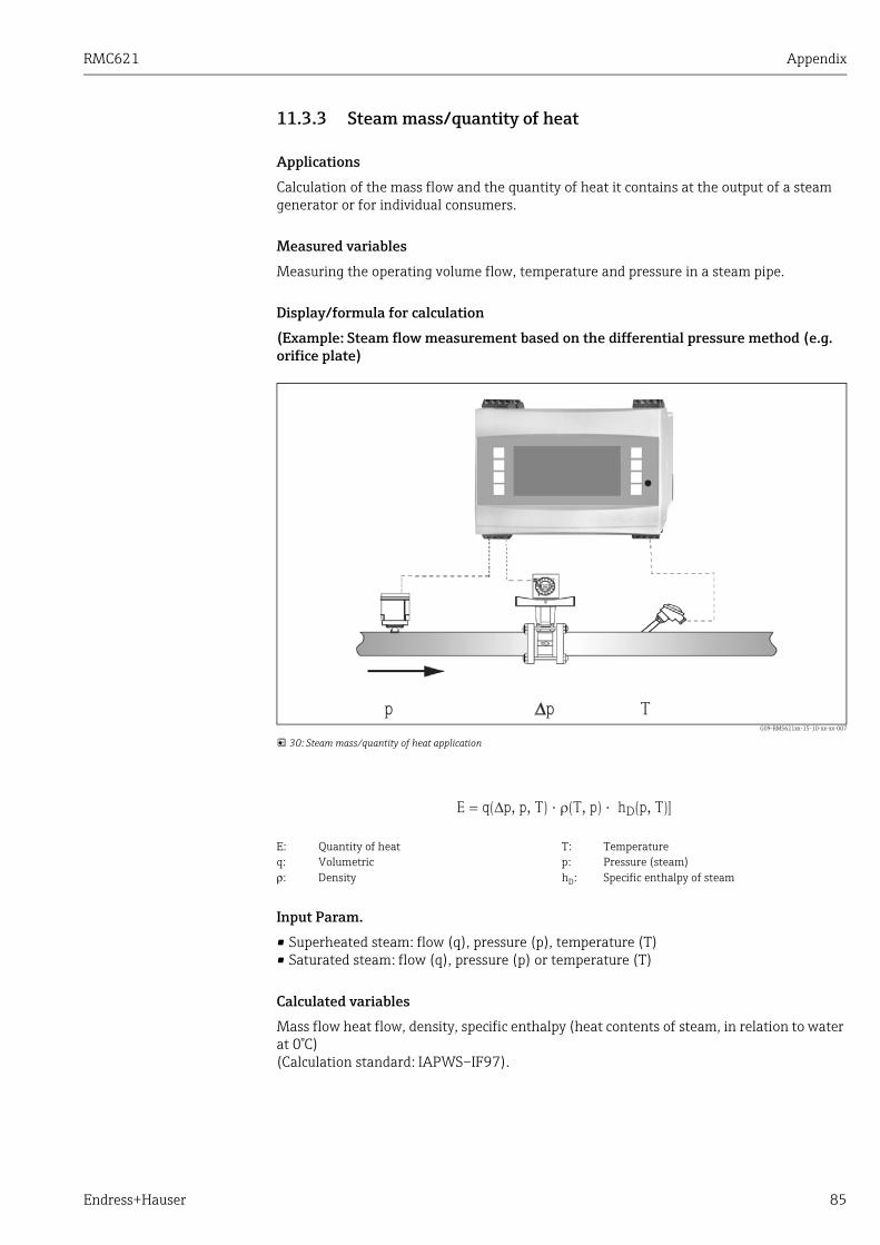
RMC621 Appendix
Endress+Hauser 85
11.3.3 Steam mass/quantity of heat
Applications
Calculation of the mass flow and the quantity of heat it contains at the output of a steam generator or for individual consumers.
Measured variables
Measuring the operating volume flow, temperature and pressure in a steam pipe.
Display/formula for calculation
(Example: Steam flow measurement based on the differential pressure method (e.g. orifice plate)
G09-RMS621xx-15-10-xx-xx-007
30: Steam mass/quantity of heat application
Input Param.
• Superheated steam: flow (q), pressure (p), temperature (T) • Saturated steam: flow (q), pressure (p) or temperature (T)
Calculated variables
Mass flow heat flow, density, specific enthalpy (heat contents of steam, in relation to water at 0°C)(Calculation standard: IAPWS–IF97).
E: Quantity of heat T: Temperatureq: Volumetric p: Pressure (steam)ρ: Density hD: Specific enthalpy of steam

Appendix RMC621
86 Endress+Hauser
Output variables/display at device
• Heat flow (performance), mass flow, operating volume flow, temperature, pressure, density, specific enthalpy.
• Totalizer: quantity of heat (energy), mass, volume, heat disturbance quantity, mass disturbance quantity.
Outputs
• All the output variables can be output via analog and pulse outputs or the interfaces (e.g. bus). In addition, relay outputs for limit value violation are also available. The number of outputs depends on the version of the device.
• If a relay is configured for "Wet Steam Alarm" it switches as soon as superheated steam is within 2°C of the saturated steam curve (condensate temperature). At the same time, an alarm message appears on the display.
Other functions
• Two-stage monitoring of steam status:Wet steam alarm: 2°C above saturated steam or condensate temperature.Phase transition alarm: alarm at saturated steam or condensate temperature.
• Configurable alarm response, i.e. the function of the counters and outputs in the event of an error (e.g. cable open circuit, phase transition) can be individually defined.
• Fully compensated iterative flow calculation following the differential pressure method in accordance with ISO 5167, resulting in highly accurate calculation even outside the design parameters.
To achieve greater accuracy and plant safety, the steam status should also be determined using three input variables for saturated steam applications as this is the only way to determine and monitor the steam status accurately (e.g. wet steam alarm function, see outputs). For this reason, please select "Superheated Steam" even for saturated steam measurement. If "Saturated Steam" is selected - i.e. one less input variable - the missing input variable is determined using the saturated steam curve stored.
Fully compensated DP measurement is available for all applications. An example is mentioned here and illustrated in the measuring system setup.For programming examples, see "Brief Operating Instructions" and Section 6.4.1.

RMC621 Appendix
Endress+Hauser 87
11.3.4 Steam/heat difference(incl. net steam)
Applications
Calculation of the steam mass flow and quantity of heat given off when the steam condensates in a heat exchanger.Alternatively also the calculation of the quantity of heat (energy) used for steam generation as well as the calculation of the steam mass flow and the quantity of heat it contains. The heat energy contained in the feed water is also taken into consideration here.
Measured variables
Measurement of the pressure and temperatures directly upstream and downstream from a heat exchanger (or steam generator). The flow can either be measured in the steam pipe or the water pipe (condensate or feed water). Optionally, you can refrain from measuring the temperature in the condensate (known as net steam measurement).
Display/formula for calculation
(Example: steam heat differential measurement, "Heating" operating mode)
G09-RMS621xx-15-10-xx-xx-008
31: Steam/heat differential application
Input Param.
• Steam line: Superheated steam: pressure (p), temperature (TD)
• Condensate pipe:Temperature (TW)
• Flow measurement (q) in the steam or condensate pipe
E: Quantity of heat TW: Temperature of water (condensate)q: Volumetric p: Pressure (steam)ρ: Density hD: Specific enthalpy of steamTD: Temperature of steam hW: Specific enthalpy of water

Appendix RMC621
88 Endress+Hauser
Calculated variables
Mass flow, heat difference (heat contents of steam minus heat contents of condensate), heat flow, density. (Calculation standard: IAPWS–IF97).
Output variables/display at device
• Heat flow (performance), mass flow, operating volume flow, temperature, pressure, density, enthalpy differential.
• Totalizer: heat (energy), mass, volume, heat disturbance quantity, mass disturbance quantity.
Outputs
• All the output variables can be output via analog and pulse outputs or the interfaces (e.g. bus). In addition, relay outputs for limit value violation are also available. The number of outputs depends on the version of the device.
• If a relay is configured for "Wet Steam Alarm" it switches as soon as superheated steam is within 2°C of the saturated steam curve (condensate temperature). At the same time, an alarm message appears on the display.
Other functions
• Two-stage monitoring of steam status:Wet steam alarm: 2°C above saturated steam or condensate temperature.Phase transition alarm: alarm at saturated steam or condensate temperature.
• Configurable alarm response, i.e. the function of the counters and outputs in the event of an error (e.g. cable open circuit, phase transition) can be individually defined.
The mounting location of the sensor for measuring the flow is determined by the operating mode. The "Heating" operating mode means that the flow transmitter is installed on the steam side; "Steam Generation" is selected if the flow is measured in the feed water (or in the condensate pipe).The application "Net Steam", i.e. refraining from using temperature measurement in the condensate pipe, is only recommended if the condensate is only marginally cooled below the boiling temperature.The application "Net Steam", i.e. refraining from using temperature measurement in the condensate pipe, is only recommended if the condensate is only marginally cooled below the boiling temperature.
To achieve greater accuracy and plant safety, the steam status should also be determined using three input variables for saturated steam applications as this is the only way to determine and monitor the steam status accurately (e.g. wet steam alarm function, see outputs). For this purpose, please select "Superheated Steam" even for saturated steam measurement.If "Saturated Steam" is selected - i.e. one less input variable - the missing input variable is determined using the saturated steam curve stored.A precondition for measuring the steam heat differential is that the system is a closed system (mass flow of condensate = mass flow of steam). If this is not the case, the flow in the condensate pipe and steam pipe should be measured separately (2 applications). The flows of energy can then be balance manually (or externally).In the case of net steam applications, the energy contents of the condensate is calculated based on the steam pressure measured.

RMC621 Appendix
Endress+Hauser 89
11.3.5 Fluid/heat differential(heating/cooling/bidirectional)
Applications
Calculation of the quantity of heat which is given off, or taken in, by a liquid heat carrier in a heat exchanger. Typical application for measuring energy in heating and cooling circuits. Bidirectional measurements are also possible depending on the temperature differential or flow direction.
Measured variables
Measuring the operating volume flow (where necessary, also the flow direction) and the temperature of the liquid directly upstream and downstream from a heat exchanger (in feed or return pipe). The density can also be directly measured (optional).
Display/formula for calculation
G09-RMC621xx-15-10-xx-xx-007
32: Application liquid/heat differential
Input Param.
• Feed pipe: flow (q), direction signal where necessary, temperature (T1)• Optional: density (ϕ)• Return pipe: temperature (T2)
Heat emission (heating) Heat absorption (cooling)
E: Quantity of heat T2: Temperature in return pipeq: Volumetric c(T1): Specific heat capacity at temperature 1ρ: Density c(T2): Specific heat capacity at temperature 2T1: Temperature in feed pipe cm: Mean specific heat capacity
Appendix RMC621
90 Endress+Hauser
Required medium data:
Specific heat capacity and liquid density
Calculated variables
Mass flow, heat flow, heat difference (difference in enthalpy), temperature differential, densityIn Bidirectional operation, "positive" and "negative" energy flows are recorded on separate counters.
Output variables/display at device
• Heat flow, mass flow, flow (operating volume), temperature 1, temperature 2, temperature differential, difference in enthalpy, density.
• Totalizer: heat (energy), mass, flow, heat disturbance quantity, disturbance quantity (plus additional counter for heat(-) and mass(-) for bidirectional operating mode).
Outputs
All the output variables can be output via analog and pulse outputs or the interfaces (e.g. bus). In addition, relay outputs for limit value violation are also available. The number of outputs depends on the version of the device.
Other functions
• Temperature differential monitoring, i.e. "Cut Off" function and alarm via relay when the minimum temperature differential is undershot
• Configurable alarm response, i.e. the function of the counters and outputs in the event of an error (e.g. cable open circuit, phase transition) can be individually defined.
Tables with data on density and heat capacity of heat carrier used (e.g. coolant) are usually supplied by the manufacturer. This data are entered in the device, though not in the case of direct density measurement.The mounting location of the flow transmitter (warm/cold side) can be defined by the user!It is recommended to install the flow transmitter at the point in the heat circuit where the temperature is closer to the ambient temperature (room temperature).In the case of bidirectional measurement with an alternating flow direction, the direction signal of the flow transmitter is fed in via an analog input. (See Section 4 "Wiring")
In the Bidirectional operating mode, the direction of the flow of energy is determined using the sign for differential temperature measurement or on the basis of the flow signal.Scaling the flow input, e.g. -100 to +100 m3/h is another possibility for bidirectional measurements. The energy flows are then balanced on a counter. (Select the Heating or Cooling operating mode here.)
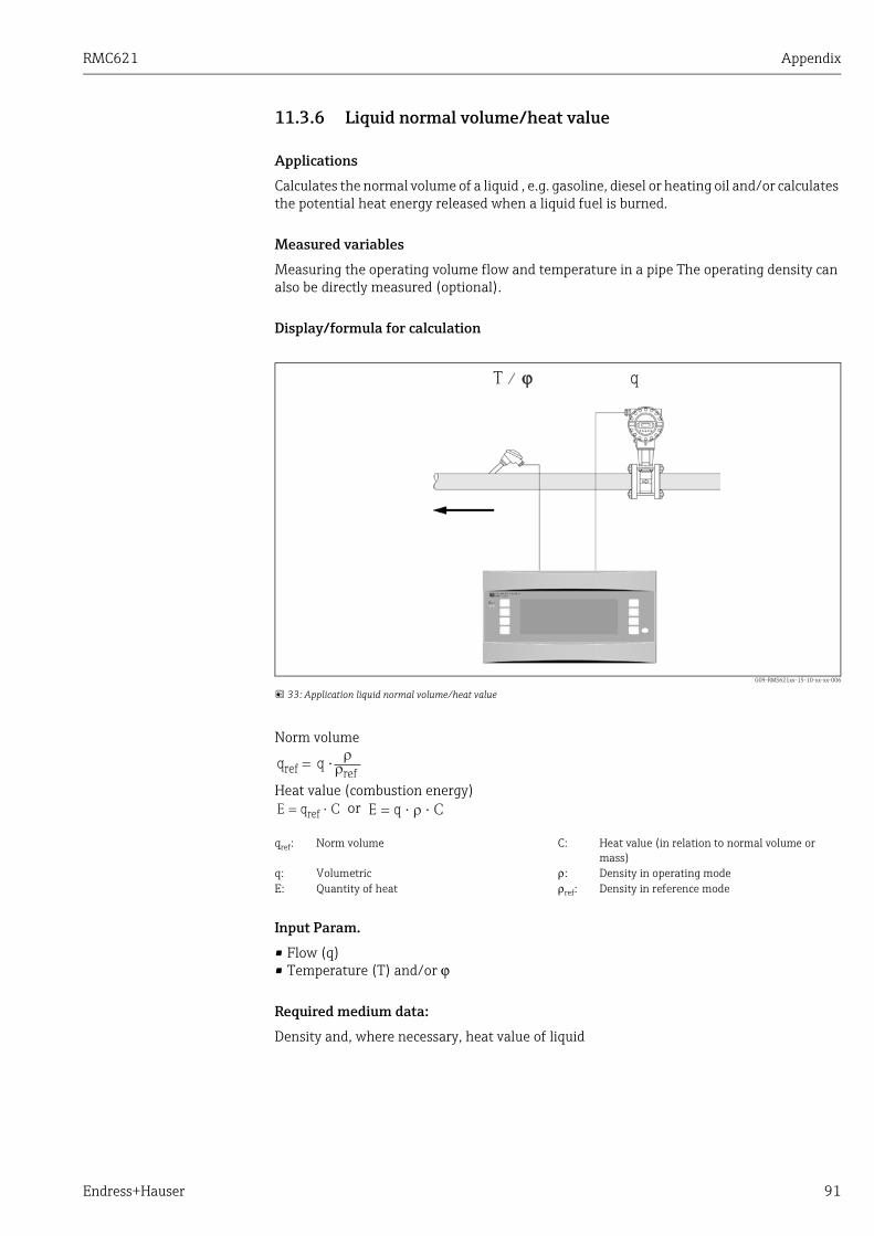
RMC621 Appendix
Endress+Hauser 91
11.3.6 Liquid normal volume/heat value
Applications
Calculates the normal volume of a liquid , e.g. gasoline, diesel or heating oil and/or calculates the potential heat energy released when a liquid fuel is burned.
Measured variables
Measuring the operating volume flow and temperature in a pipe The operating density can also be directly measured (optional).
Display/formula for calculation
G09-RMS621xx-15-10-xx-xx-006
33: Application liquid normal volume/heat value
Norm volume
Heat value (combustion energy) or
Input Param.
• Flow (q) • Temperature (T) and/or ϕ
Required medium data:
Density and, where necessary, heat value of liquid
T / ϕϕ q
qref: Norm volume C: Heat value (in relation to normal volume or mass)
q: Volumetric ρ: Density in operating modeE: Quantity of heat ρref: Density in reference mode
Appendix RMC621
92 Endress+Hauser
Calculated variables
Normal volume, mass flow, heat flow, density (combustion energy)
Output variables/display at device
• Normal volume, heat flow (performance), mass flow, operating volume flow, temperature, density.
• Totalizer: heat (energy), mass, normal volume, operating volume, heat disturbance quantity, mass disturbance quantity, normal volume disturbance quantity.
Outputs
All the output variables can be output via analog and pulse outputs or the interfaces (e.g. bus). In addition, relay outputs for limit value violation are also available. The number of outputs depends on the version of the device.
Other functions
Configurable alarm response, i.e. the function of the counters and outputs in the event of an error (e.g. cable open circuit, phase transition) can be individually defined.
The heat value of a liquid is entered in the device as a mean value.The liquid density data must be stored in the device (e.g. via table). These data are not entered for direct density measurement. Specification of the heat value of the liquid is optional. The density must be entered at standard conditions to calculate the normal volume.The density must be entered at 15°C or 60°F for calculations in accordance with API 2540.
The heat performance (combustion energy) is calculated based on the mean heat value of the fuel.The operating density and normal volume flow of petroleum products (petroleum, gasoline, heating oil, kerosene) are calculated according to the API 2540 standard (available as software option).
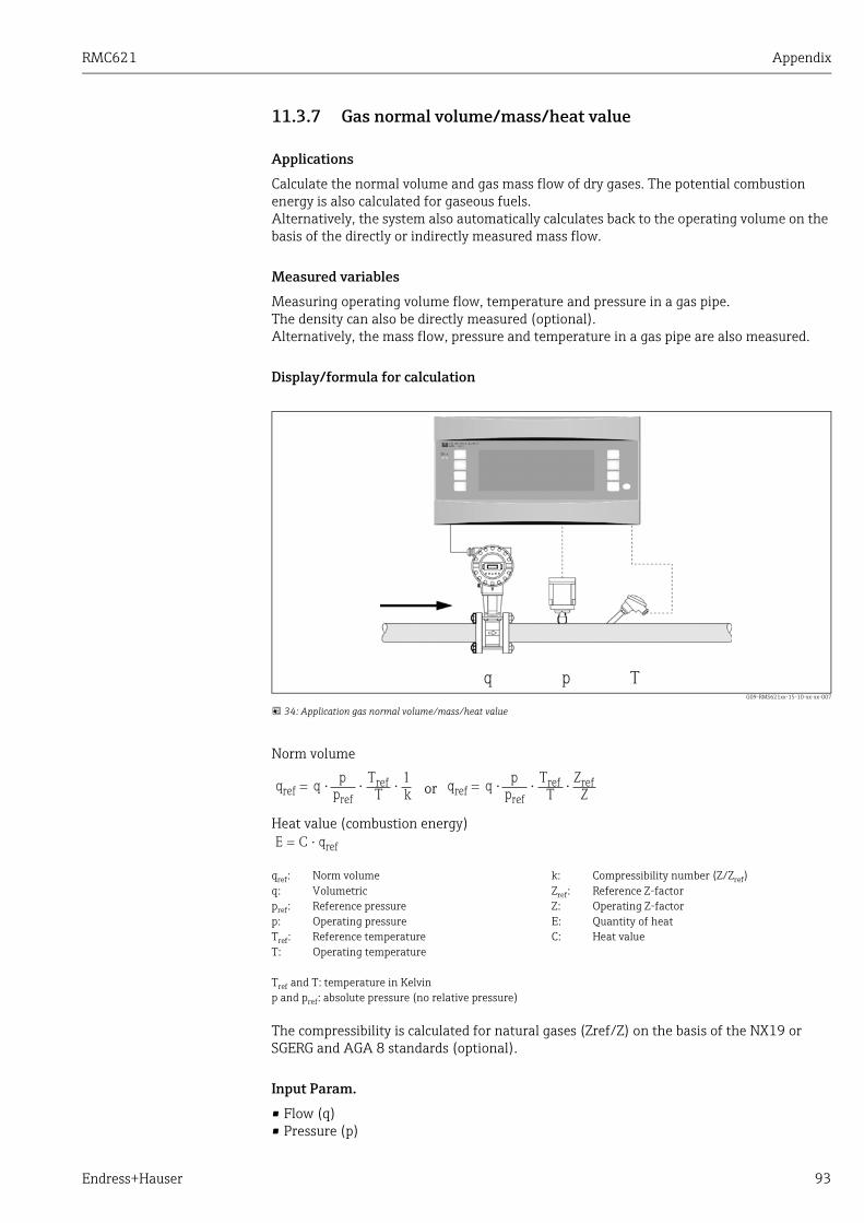
RMC621 Appendix
Endress+Hauser 93
11.3.7 Gas normal volume/mass/heat value
Applications
Calculate the normal volume and gas mass flow of dry gases. The potential combustion energy is also calculated for gaseous fuels.Alternatively, the system also automatically calculates back to the operating volume on the basis of the directly or indirectly measured mass flow.
Measured variables
Measuring operating volume flow, temperature and pressure in a gas pipe.The density can also be directly measured (optional).Alternatively, the mass flow, pressure and temperature in a gas pipe are also measured.
Display/formula for calculation
G09-RMS621xx-15-10-xx-xx-007
34: Application gas normal volume/mass/heat value
Norm volume
or
Heat value (combustion energy)
The compressibility is calculated for natural gases (Zref/Z) on the basis of the NX19 or SGERG and AGA 8 standards (optional).
Input Param.
• Flow (q)• Pressure (p)
q p T
qref: Norm volume k: Compressibility number (Z/Zref)q: Volumetric Zref: Reference Z-factorpref: Reference pressure Z: Operating Z-factorp: Operating pressure E: Quantity of heatTref: Reference temperature C: Heat valueT: Operating temperature
Tref and T: temperature in Kelvinp and pref: absolute pressure (no relative pressure)

Appendix RMC621
94 Endress+Hauser
• Temperature (T) and/or ϕ
Required medium data:
Ideally the critical pressure and temperature as well as the reference density should be entered in the device for gaseous media or gas mixtures not stored (parameter for real gas equation). If no medium data whatsoever are known, the calculation is made based on the ideal gas law.For natural gas, the gas composition must be entered in Mol % (= Vol %) and the fuel value (Ho).
Calculated variables
Gas normal volume and gas mass flow, density, compressibility (Z-factor), heat flow (combustion heat).
Output variables/display at device
• Normal volume flow, operating volume flow, mass flow, heat flow (combustion energy), temperature, pressure, density, compressibility number (zn/zb).
• Totalizer: normal volume, volume, mass, heat, normal volume disturbance quantity, mass disturbance quantity, heat disturbance quantity.
Outputs
All the output variables can be output via analog and pulse outputs or the interfaces (e.g. bus). In addition, relay outputs for limit value violation are also available. The number of outputs depends on the version of the device.
Other functions
Configurable alarm response, i.e. the function of the counters and outputs in the event of an error (e.g. cable open circuit, phase transition) can be individually defined.For a programming example, see the "Brief Operating Instructions" section.
All medium data are stored in the device for air, carbon dioxide, oxygen, nitrogen, methane, acetylene, argon, hydrogen and ammonia (gaseous).The heat value of a gas is entered as a mean value (usually in relation to reference conditions).Normal conditions (temperature and pressure at reference conditions) can be freely configured.The E+H applicator can be used to determine the required data for gases and gas mixtures (e.g.biogas) (with the exception of heat value data).If a density sensor is used, the medium data are not entered.
The calculation is made taking into account the pressure and temperature effect, and the compressibility of the gas, which describes the deviation of a gas from ideal gas. The compressibility (Z-factor) of the gas is determined using measurement standards or user-defined tables depending on the type of gas. The Z-factor can also be entered as a mean value.If a sensor is used for the direct measurement of the mass flow, the normal volume is calculated and calculated back to the operating volume based on operating pressure and temperature.Scaling the flow input, e.g. -100 to +100 m3/h is another possibility for bidirectional measurements. The energy flows are then balanced on a counter.
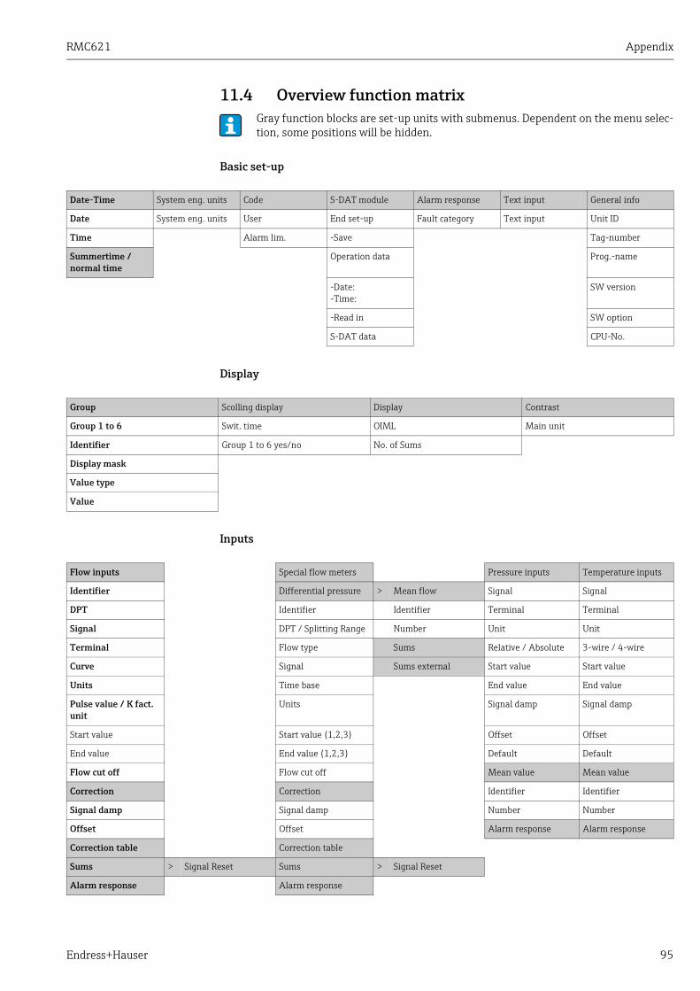
RMC621 Appendix
Endress+Hauser 95
11.4 Overview function matrix
Basic set-up
Display
Inputs
Gray function blocks are set-up units with submenus. Dependent on the menu selec-tion, some positions will be hidden.
Date-Time System eng. units Code S-DAT module Alarm response Text input General info
Date System eng. units User End set-up Fault category Text input Unit ID
Time Alarm lim. -Save Tag-number
Summertime / normal time
Operation data Prog.-name
-Date:-Time:
SW version
-Read in SW option
S-DAT data CPU-No.
Group Scolling display Display Contrast
Group 1 to 6 Swit. time OIML Main unit
Identifier Group 1 to 6 yes/no No. of Sums
Display mask
Value type
Value
Flow inputs Special flow meters Pressure inputs Temperature inputs
Identifier Differential pressure > Mean flow Signal Signal
DPT Identifier Identifier Terminal Terminal
Signal DPT / Splitting Range Number Unit Unit
Terminal Flow type Sums Relative / Absolute 3-wire / 4-wire
Curve Signal Sums external Start value Start value
Units Time base End value End value
Pulse value / K fact. unit
Units Signal damp Signal damp
Start value Start value (1,2,3) Offset Offset
End value End value (1,2,3) Default Default
Flow cut off Flow cut off Mean value Mean value
Correction Correction Identifier Identifier
Signal damp Signal damp Number Number
Offset Offset Alarm response Alarm response
Correction table Correction table
Sums > Signal Reset Sums > Signal Reset
Alarm response Alarm response
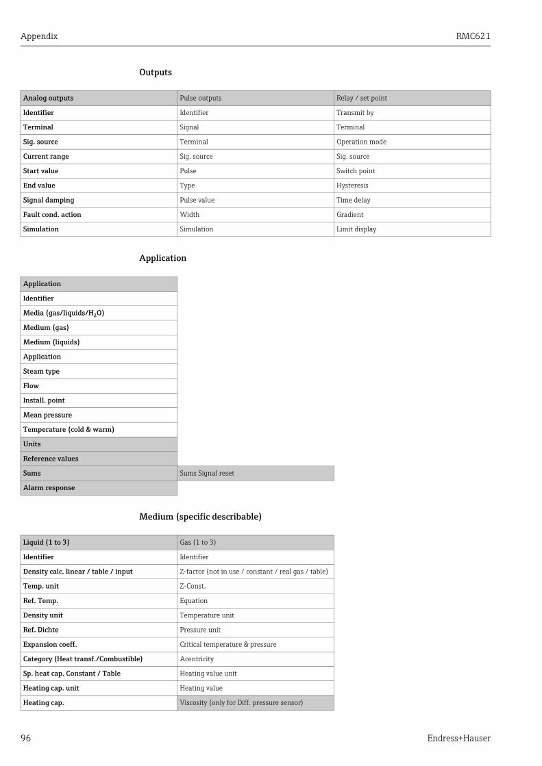
Appendix RMC621
96 Endress+Hauser
Outputs
Application
Medium (specific describable)
Analog outputs Pulse outputs Relay / set point
Identifier Identifier Transmit by
Terminal Signal Terminal
Sig. source Terminal Operation mode
Current range Sig. source Sig. source
Start value Pulse Switch point
End value Type Hysteresis
Signal damping Pulse value Time delay
Fault cond. action Width Gradient
Simulation Simulation Limit display
Application
Identifier
Media (gas/liquids/H2O)
Medium (gas)
Medium (liquids)
Application
Steam type
Flow
Install. point
Mean pressure
Temperature (cold & warm)
Units
Reference values
Sums Sums Signal reset
Alarm response
Liquid (1 to 3) Gas (1 to 3)
Identifier Identifier
Density calc. linear / table / input Z-factor (not in use / constant / real gas / table)
Temp. unit Z-Const.
Ref. Temp. Equation
Density unit Temperature unit
Ref. Dichte Pressure unit
Expansion coeff. Critical temperature & pressure
Category (Heat transf./Combustible) Acentricity
Sp. heat cap. Constant / Table Heating value unit
Heating cap. unit Heating value
Heating cap. Viscosity (only for Diff. pressure sensor)
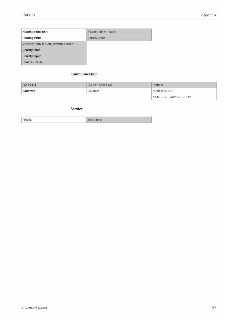
RMC621 Appendix
Endress+Hauser 97
Communication
Service
Heating value unit Z-factor table / matrix
Heating value Density input
Viscosity (only for Diff. pressure sensor)
Density table
Density input
Heat cap. table
RS485 (1) RS232 / RS485 (2) Profibus
Baudrate Baudrate Number (0…48)
Addr. 0…4 … Addr. 235…239
PRESET Total sums
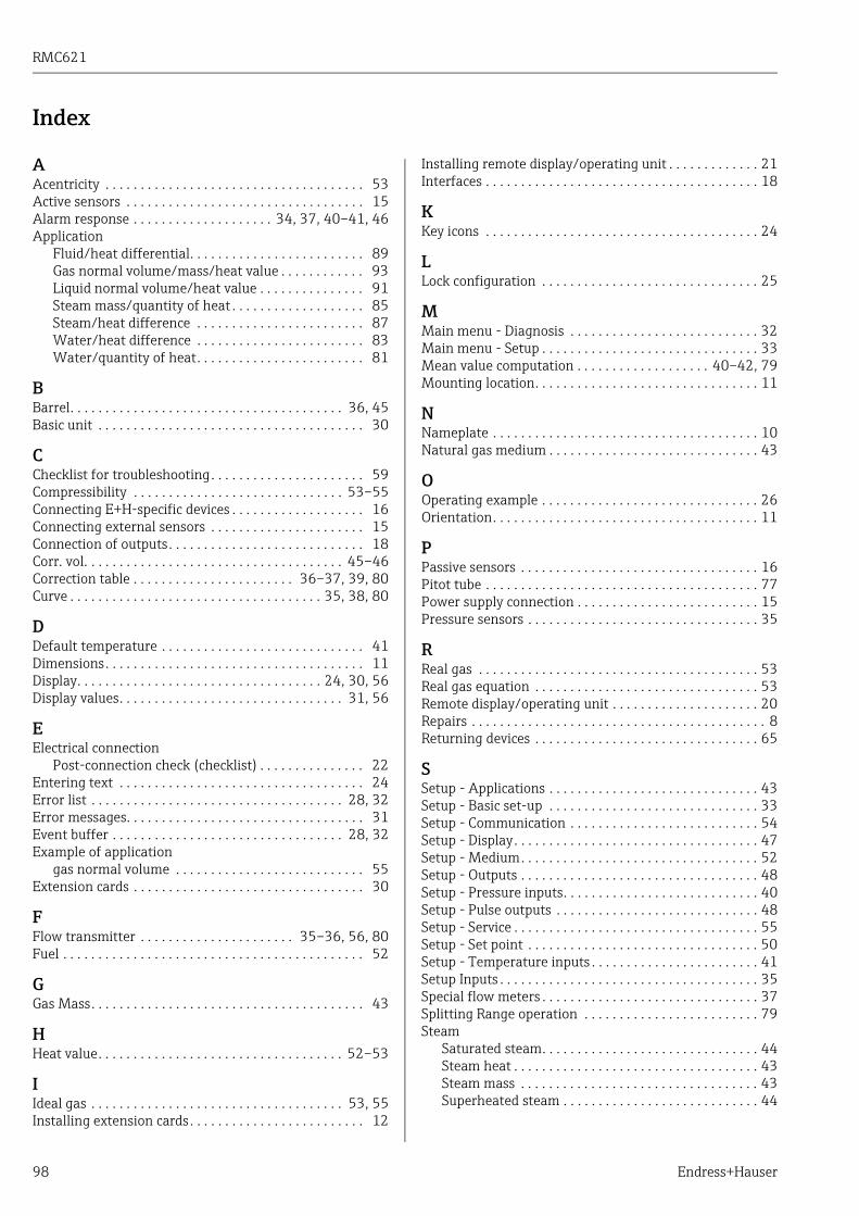
RMC621
98 Endress+Hauser
Index
AAcentricity . . . . . . . . . . . . . . . . . . . . . . . . . . . . . . . . . . . . . 53Active sensors . . . . . . . . . . . . . . . . . . . . . . . . . . . . . . . . . . 15Alarm response . . . . . . . . . . . . . . . . . . . . 34, 37, 40–41, 46Application
Fluid/heat differential. . . . . . . . . . . . . . . . . . . . . . . . . 89Gas normal volume/mass/heat value . . . . . . . . . . . . 93Liquid normal volume/heat value . . . . . . . . . . . . . . . 91Steam mass/quantity of heat . . . . . . . . . . . . . . . . . . . 85Steam/heat difference . . . . . . . . . . . . . . . . . . . . . . . . 87Water/heat difference . . . . . . . . . . . . . . . . . . . . . . . . 83Water/quantity of heat. . . . . . . . . . . . . . . . . . . . . . . . 81
BBarrel. . . . . . . . . . . . . . . . . . . . . . . . . . . . . . . . . . . . . . . 36, 45Basic unit . . . . . . . . . . . . . . . . . . . . . . . . . . . . . . . . . . . . . . 30
CChecklist for troubleshooting. . . . . . . . . . . . . . . . . . . . . . 59Compressibility . . . . . . . . . . . . . . . . . . . . . . . . . . . . . . 53–55Connecting E+H-specific devices . . . . . . . . . . . . . . . . . . . 16Connecting external sensors . . . . . . . . . . . . . . . . . . . . . . 15Connection of outputs. . . . . . . . . . . . . . . . . . . . . . . . . . . . 18Corr. vol. . . . . . . . . . . . . . . . . . . . . . . . . . . . . . . . . . . . . 45–46Correction table . . . . . . . . . . . . . . . . . . . . . . . 36–37, 39, 80Curve . . . . . . . . . . . . . . . . . . . . . . . . . . . . . . . . . . . . 35, 38, 80
DDefault temperature . . . . . . . . . . . . . . . . . . . . . . . . . . . . . 41Dimensions. . . . . . . . . . . . . . . . . . . . . . . . . . . . . . . . . . . . . 11Display. . . . . . . . . . . . . . . . . . . . . . . . . . . . . . . . . . . 24, 30, 56Display values. . . . . . . . . . . . . . . . . . . . . . . . . . . . . . . . 31, 56
EElectrical connection
Post-connection check (checklist) . . . . . . . . . . . . . . . 22Entering text . . . . . . . . . . . . . . . . . . . . . . . . . . . . . . . . . . . 24Error list . . . . . . . . . . . . . . . . . . . . . . . . . . . . . . . . . . . . 28, 32Error messages. . . . . . . . . . . . . . . . . . . . . . . . . . . . . . . . . . 31Event buffer . . . . . . . . . . . . . . . . . . . . . . . . . . . . . . . . . 28, 32Example of application
gas normal volume . . . . . . . . . . . . . . . . . . . . . . . . . . . 55Extension cards . . . . . . . . . . . . . . . . . . . . . . . . . . . . . . . . . 30
FFlow transmitter . . . . . . . . . . . . . . . . . . . . . . 35–36, 56, 80Fuel . . . . . . . . . . . . . . . . . . . . . . . . . . . . . . . . . . . . . . . . . . . 52
GGas Mass. . . . . . . . . . . . . . . . . . . . . . . . . . . . . . . . . . . . . . . 43
HHeat value. . . . . . . . . . . . . . . . . . . . . . . . . . . . . . . . . . . 52–53
IIdeal gas . . . . . . . . . . . . . . . . . . . . . . . . . . . . . . . . . . . . 53, 55Installing extension cards. . . . . . . . . . . . . . . . . . . . . . . . . 12
Installing remote display/operating unit . . . . . . . . . . . . . 21Interfaces . . . . . . . . . . . . . . . . . . . . . . . . . . . . . . . . . . . . . . . 18
KKey icons . . . . . . . . . . . . . . . . . . . . . . . . . . . . . . . . . . . . . . . 24
LLock configuration . . . . . . . . . . . . . . . . . . . . . . . . . . . . . . . 25
MMain menu - Diagnosis . . . . . . . . . . . . . . . . . . . . . . . . . . . 32Main menu - Setup . . . . . . . . . . . . . . . . . . . . . . . . . . . . . . . 33Mean value computation . . . . . . . . . . . . . . . . . . . 40–42, 79Mounting location. . . . . . . . . . . . . . . . . . . . . . . . . . . . . . . . 11
NNameplate . . . . . . . . . . . . . . . . . . . . . . . . . . . . . . . . . . . . . . 10Natural gas medium . . . . . . . . . . . . . . . . . . . . . . . . . . . . . . 43
OOperating example . . . . . . . . . . . . . . . . . . . . . . . . . . . . . . . 26Orientation. . . . . . . . . . . . . . . . . . . . . . . . . . . . . . . . . . . . . . 11
PPassive sensors . . . . . . . . . . . . . . . . . . . . . . . . . . . . . . . . . . 16Pitot tube . . . . . . . . . . . . . . . . . . . . . . . . . . . . . . . . . . . . . . . 77Power supply connection . . . . . . . . . . . . . . . . . . . . . . . . . . 15Pressure sensors . . . . . . . . . . . . . . . . . . . . . . . . . . . . . . . . . 35
RReal gas . . . . . . . . . . . . . . . . . . . . . . . . . . . . . . . . . . . . . . . . 53Real gas equation . . . . . . . . . . . . . . . . . . . . . . . . . . . . . . . . 53Remote display/operating unit . . . . . . . . . . . . . . . . . . . . . 20Repairs . . . . . . . . . . . . . . . . . . . . . . . . . . . . . . . . . . . . . . . . . . 8Returning devices . . . . . . . . . . . . . . . . . . . . . . . . . . . . . . . . 65
SSetup - Applications . . . . . . . . . . . . . . . . . . . . . . . . . . . . . . 43Setup - Basic set-up . . . . . . . . . . . . . . . . . . . . . . . . . . . . . . 33Setup - Communication . . . . . . . . . . . . . . . . . . . . . . . . . . . 54Setup - Display. . . . . . . . . . . . . . . . . . . . . . . . . . . . . . . . . . . 47Setup - Medium. . . . . . . . . . . . . . . . . . . . . . . . . . . . . . . . . . 52Setup - Outputs . . . . . . . . . . . . . . . . . . . . . . . . . . . . . . . . . . 48Setup - Pressure inputs. . . . . . . . . . . . . . . . . . . . . . . . . . . . 40Setup - Pulse outputs . . . . . . . . . . . . . . . . . . . . . . . . . . . . . 48Setup - Service . . . . . . . . . . . . . . . . . . . . . . . . . . . . . . . . . . . 55Setup - Set point . . . . . . . . . . . . . . . . . . . . . . . . . . . . . . . . . 50Setup - Temperature inputs . . . . . . . . . . . . . . . . . . . . . . . . 41Setup Inputs . . . . . . . . . . . . . . . . . . . . . . . . . . . . . . . . . . . . . 35Special flow meters . . . . . . . . . . . . . . . . . . . . . . . . . . . . . . . 37Splitting Range operation . . . . . . . . . . . . . . . . . . . . . . . . . 79Steam
Saturated steam. . . . . . . . . . . . . . . . . . . . . . . . . . . . . . . 44Steam heat . . . . . . . . . . . . . . . . . . . . . . . . . . . . . . . . . . . 43Steam mass . . . . . . . . . . . . . . . . . . . . . . . . . . . . . . . . . . 43Superheated steam . . . . . . . . . . . . . . . . . . . . . . . . . . . . 44

RMC621
Endress+Hauser 99
TTemperature sensors. . . . . . . . . . . . . . . . . . . . . . . . . . . . . 16Terminal assignment . . . . . . . . . . . . . . . . . . . . . . . . . . . . 13Terminal assignment of temperature extension card. . 20Terminal assignment of Universal extension card . . . . 19Totalizers . . . . . . . . . . . . . . . . . . . . . . . . . . . . . . . . . . . . . . 46
UUnits . . . . . . . . . . . . . . . . . . . . . . . . . . . . . . . . . . . . . . . . . . 45

RMC621
100 Endress+Hauser
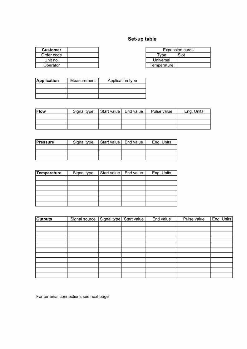
Set-up table
CustomerOrder code Type Slot
Unit no. UniversalOperator Temperature
Application Measurement
Flow Signal type Start value End value Pulse value Eng. Units
Pressure Signal type Start value End value Eng. Units
Temperature Signal type Start value End value Eng. Units
Outputs Signal source Signal type Start value End value Pulse value Eng. Units
For terminal connections see next page
Expansion cards
Application type
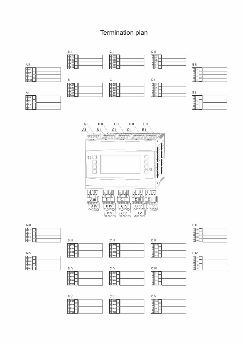


www.addresses.endress.com


