

OPERAOPERAOPERAOPERAOPERATTTTTOR'SOR'SOR'SOR'SOR'SGUIDEGUIDEGUIDEGUIDEGUIDEMODMODMODMODMODALALALALAL
000 700 207/09.99./Redditch
Page 2
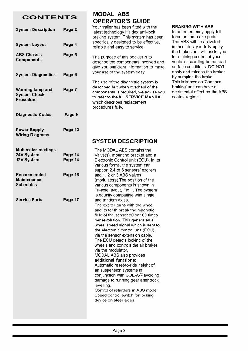
CONTENTS MODAL ABSOPERATOR'S GUIDE
BRAKING WITH ABSIn an emergency apply fullforce on the brake pedal.The ABS will be activatedimmediately you fully applythe brakes and will assist youin retaining control of yourvehicle according to the roadsurface conditions. DO NOTapply and release the brakesby pumping the brake.This is known as 'Cadencebraking' and can have adetrimental effect on the ABScontrol regime.
The MODAL ABS contains theValve(s), mounting bracket and aElectronic Control unit (ECU). In itsvarious forms, the system cansupport 2,4,or 6 sensors/ excitersand 1, 2 or 3 ABS valves(modulators).The position of thevarious components is shown inTri-axle layout, Fig 1. The systemis equally compatible with singleand tandem axles.The exciter turns with the wheeland its teeth break the magneticfield of the sensor 80 or 100 timesper revolution. This generates awheel speed signal which is sent tothe electronic control unit (ECU)via the sensor extension cable.The ECU detects locking of thewheels and controls the air brakesvia the modulator.MODAL ABS also providesadditional functions:Automatic reset-to-ride height ofair suspension systems inconjunction with COLAS avoidingdamage to running gear after docklevelling.Control of retarders in ABS mode.Speed control switch for lockingdevice on steer axles.
SYSTEM DESCRIPTION
Your trailer has been fitted with thelatest technology Haldex anti-lockbraking system. This system has beenspecifically designed to be effective,reliable and easy to service.
The purpose of this booklet is todescribe the components involved andgive you sufficient information to makeyour use of the system easy.
The use of the diagnostic system isdescribed but when overhaul of thecomponents is required, we advise youto refer to the full SERVICE MANUALwhich describes replacementprocedures fully.
System Description Page 2
System Layout Page 4
ABS Chassis Page 5Components
System Diagnostics Page 6
Warning lamp and Page 7System CheckProcedure
Diagnostic Codes Page 9
Power Supply Page 12Wiring Diagrams
Multimeter readings24V System Page 1412V System Page 14
Recommended Page 16MaintenanceSchedules
Service Parts Page 17
®
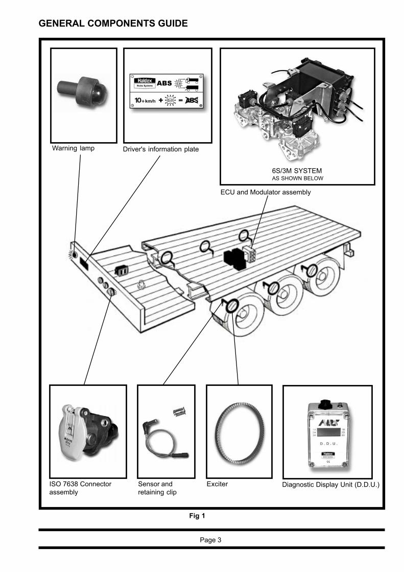
GENERAL COMPONENTS GUIDE
Warning lamp
ISO 7638 Connectorassembly
Sensor andretaining clip
Exciter
Driver's information plate
Diagnostic Display Unit (D.D.U.)
Fig 1
Page 3
ECU and Modulator assembly
6S/3M SYSTEMAS SHOWN BELOW
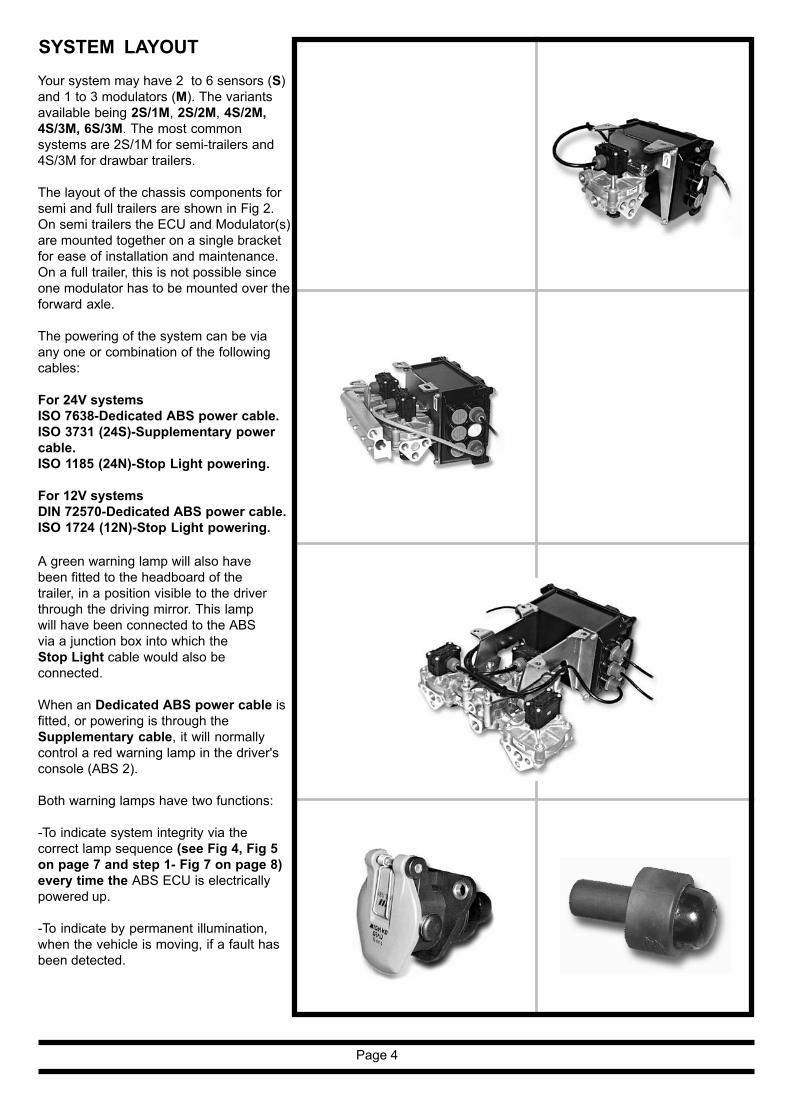
SYSTEM LAYOUT
Page 4
Your system may have 2 to 6 sensors (S)and 1 to 3 modulators (M). The variantsavailable being 2S/1M, 2S/2M, 4S/2M,4S/3M, 6S/3M. The most commonsystems are 2S/1M for semi-trailers and4S/3M for drawbar trailers.
The layout of the chassis components forsemi and full trailers are shown in Fig 2.On semi trailers the ECU and Modulator(s)are mounted together on a single bracketfor ease of installation and maintenance.On a full trailer, this is not possible sinceone modulator has to be mounted over theforward axle.
The powering of the system can be viaany one or combination of the followingcables:
For 24V systemsISO 7638-Dedicated ABS power cable.ISO 3731 (24S)-Supplementary powercable.ISO 1185 (24N)-Stop Light powering.
For 12V systemsDIN 72570-Dedicated ABS power cable.ISO 1724 (12N)-Stop Light powering.
A green warning lamp will also havebeen fitted to the headboard of thetrailer, in a position visible to the driverthrough the driving mirror. This lampwill have been connected to the ABSvia a junction box into which theStop Light cable would also beconnected.
When an Dedicated ABS power cable isfitted, or powering is through theSupplementary cable, it will normallycontrol a red warning lamp in the driver'sconsole (ABS 2).
Both warning lamps have two functions:
-To indicate system integrity via thecorrect lamp sequence (see Fig 4, Fig 5on page 7 and step 1- Fig 7 on page 8)every time the ABS ECU is electricallypowered up.
-To indicate by permanent illumination,when the vehicle is moving, if a fault hasbeen detected.
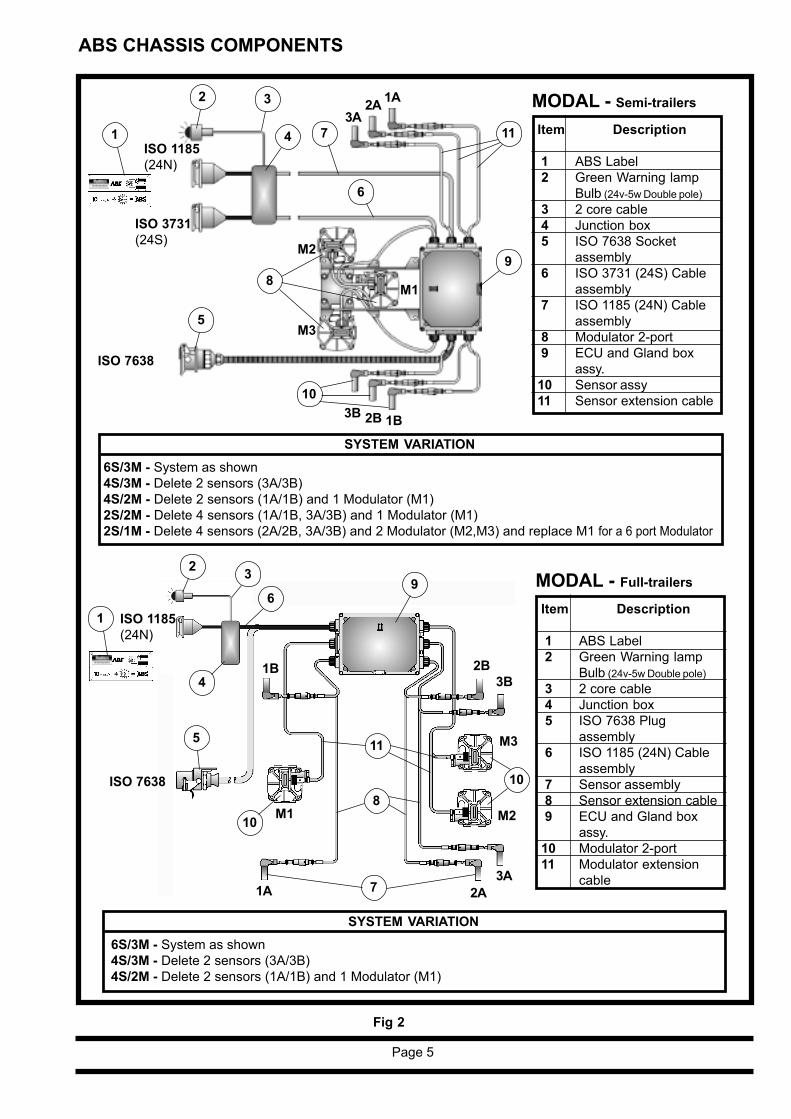
ABS CHASSIS COMPONENTS
ISO 1185(24N)
ISO 7638
ISO 3731(24S)
1
2
3A2A
1
2 3
ISO 7638
ISO 1185(24N)
Fig 2
Page 5
3B2B
7
SYSTEM VARIATION6S/3M - System as shown4S/3M - Delete 2 sensors (3A/3B)4S/2M - Delete 2 sensors (1A/1B) and 1 Modulator (M1)2S/2M - Delete 4 sensors (1A/1B, 3A/3B) and 1 Modulator (M1)2S/1M - Delete 4 sensors (2A/2B, 3A/3B) and 2 Modulator (M2,M3) and replace M1 for a 6 port Modulator
SYSTEM VARIATION6S/3M - System as shown4S/3M - Delete 2 sensors (3A/3B)4S/2M - Delete 2 sensors (1A/1B) and 1 Modulator (M1)
MODAL - Semi-trailers
Item Description
1 ABS Label 2 Green Warning lamp
Bulb (24v-5w Double pole) 3 2 core cable 4 Junction box5 ISO 7638 Socket
assembly6 ISO 3731 (24S) Cable
assembly 7 ISO 1185 (24N) Cable
assembly 8 Modulator 2-port 9 ECU and Gland box
assy.10 Sensor assy11 Sensor extension cable
MODAL - Full-trailers
Item Description
1 ABS Label 2 Green Warning lamp
Bulb (24v-5w Double pole) 3 2 core cable 4 Junction box5 ISO 7638 Plug
assembly6 ISO 1185 (24N) Cable
assembly 7 Sensor assembly 8 Sensor extension cable 9 ECU and Gland box
assy.10 Modulator 2-port11 Modulator extension
cable
3
4 73A
2A 1A
3B 2B 1B
M2
M3
M1
6
98
5
10
11
5
4
11
810
10
9
1B
1A
M3
M2M1
6

Fig 3
SYSTEM DIAGNOSTICS
An important feature of the MODALsystem is that it provides on boarddiagnostics. The system displays arange of codes, which allow rapiddiagnosis of the problem should oneoccur.
Page 6
Both devices give two types ofdisplay:
-Horizontal bars indicate the positionof effective speed sensors when thewheels are rotated.
-A two digit display can be interpretedfrom the list of codes shown on pages9, 10 and 11.
The diagnostic codes can be readeither from the Total On-boardDiagnostic Display (TODD) or via theremote Diagnostic Display Unit(DDU).The TODD is located in the lid of theECU box. This can be accessed byundoing the 4 cap screws holding thelid in position and opening the lid onits side hinge. The position of theTODD display is indicated in Fig 3.
The DDU can be connected remotelyvia the socket on the underside of theECU housing indicated in Fig 3.
DDU Plug locates ingland box outletsocket in base ofgland box
Push button forcode switching
Gland box incorporating ECU andTODD
DDU socket located in under-side of gland box
TODD
ECU

Page 7
RED warning lamp located onthe driver's console of the towingvehicle is operated from theISO 7638 (or ISO 3731 - 24S)power cable only when the ABSis powered by the ignition switch.Fig 4.
GREEN warning lamp mountedon the headboard of the trailerand is operated from theISO 1185 (24N) connector whenthe ABS is powered only fromthe stop lamp power supply i.e.when the brake pedal isdepressed. Fig 5.
WARNING LAMP ANDSYSTEM CHECKPROCEDURE
The warning lamp(s) functiondepends on which powersupply is used:
1
REDLamp
Fig 4
GREENLamp
Fig 5
Note: If a dedicated power source isavailable to the ABS from the ISO 7638connector, or the ISO 3731 (24S), thensystem integrity will be indicated by theRED cab mounted warning lamp whichbecomes the primary ABS statusindicator, the GREEN trailer lampbecomes the secondary indicator andduplicates the RED cab mounted lampfunction when the stop lamp circuit isoperated. Fig 6.
REDLamp
GREENLamp
Fig 6
On power up of the system, the warninglamp(s) must illuminate in the followingsequence in order to show a fault-freesystem:
ON for 2.5 seconds = Bulb OK andsystem self-checking.
OFF for 1 second = Systemself-checkedand preparingto checksensors.
ON until moving = Systemwaiting forvehicle tomove above10 km/h inorder to checkthat thesensors areworking.
OFF = Once thevehicle ismoving above10 km/h andthe lamp(s)goes (go) out,the electronicsystem is fullychecked.
2 During the self-check procedure,the system operates eachmodulator solenoid seperatelyonce.This operation will be audible asan exhaust of air from the valve.If more than one modulator isfitted, the exhaust noise fromeach valve will be separated byapproximately 1 second.
Once these two checks aremade with correct results, nofurther checks are required.
If the results are not satisfactory,the TODD or DDU should beused to establish the diagnosis.
This information is describedvisually in Fig 7 (2S/1M Semitrailer) and Fig 8 (4S/3M Fulltrailer) on page 8.
3

ABS TEST PROCEDURE - SUMMARY
Page 8
STEP
2STEP
3
Apply foot brake and turn ignition on :STEP 1 WATCH RED and GREEN WARNING LAMP.STEP 2 Listen for BLOW DOWN.STEP 3 REFER TO DIAGNOSTIC DISPLAY CODE on DDU or TODD
Release foot brakeSPIN EACH SENSED WHEEL IN TURN, REFER TO DIAGNOSTIC DISPLAY CODE INDICATION.
DDU CODE
STEP
1
Example :2S/1M Semi trailer Key
ModulatorBlowdown
Modulator
O.K.
NOT O.K.
M
1rev / 2sec
STEP
2STEP
3DDU CODE
STEP
1
Example :4S/3M Full trailer Key
ModulatorBlowdownModulatorRed
O.K.
NOT O.K.
M
1rev / 2sec
ModulatorBlueM
ModulatorYellowM
1
3
2
1 2 3
Fig 8
Fig 7

CODE DISPLAYED
DDU
BLANK DISPLAY No supply on ignition switched line.Possible causes:Fuse blown.DDU or cable fault.Open circuit B -
SENSOR BAR Bar displayed = Sensor output O.K.Bar not displayed = Sensor output too low
00 System is O.K. vehicle is moving01 1A Sensor/wiring open or short circuit02 1B Sensor/wiring open or short circuit03 2A Sensor/wiring open or short circuit04 2B Sensor/wiring open or short circuit05 3A Sensor/wiring open or short circuit06 3B Sensor/wiring open or short circuit07 System is O.K. vehicle is stationary08 Retarder / Wiring open circuit09 Retarder / Wiring short circuitOC Reset to ride / Wiring open circuitOA Reset to ride / Wiring short circuitOE Warning lamp circuit fault
LOW SENSOR OUTPUT GROUP
11 1A Sensor system fault12 1B Sensor system fault13 2A Sensor system fault14 2B Sensor system fault15 3A Sensor system fault16 3B Sensor system fault
Possible causes:Sensor worn, maladjusted sensor, wiring open or short circuit.
20 Incorrect exciter type.Possible causes:Exciter tooth count different each side of axle.
INTERMITTENT LOW SENSOR OUTPUT GROUP
21 1A Sensor system fault22 1B Sensor system fault23 2A Sensor system fault24 2B Sensor system fault25 3A Sensor system fault26 3B Sensor system fault
Possible causes:Loose sensor, connection, bracket or exciter.Damaged exciter.Maladjusted sensor or worn sensor cable insulation.
DIAGNOSTIC CODES
If a diagnostic code not listed below is displayed check for intermittent sensor and wiring faults.Refer to Service Manual for detailed diagnostic testing procedures.
Page 9

CODE DISPLAYED
DDU
37 A diagnostic code sent to the ABS ECU to activate themultiple light sequence.
ONE WHEEL WITH SLOW RECOVERY GROUP
40 Sensor wiring crossed across an axle41 Slow recovery of one wheel of red channel42 Slow recovery of one wheel of blue channel43 Slow recovery of one wheel of yellow channel
Possible causes:Slow brake release, foundation brake mechanical faults, drybearings, broken spring, restricted pipingCheck for kinks and blockages etc.Incorrect piping, WiringModulator fault
OPEN CIRCUIT MODULATOR SOLENOID ORSOLENOID WIRING GROUP
61 Hold solenoid circuit fault, red channel62 Hold solenoid circuit fault, blue channel63 Hold solenoid circuit fault, yellow channel67 Dump solenoid circuit fault, red channel68 Dump solenoid circuit fault, blue channel69 Dump solenoid circuit fault, yellow channel
SHORT CIRCUIT ACROSS MODULATOR SOLENOID ORSOLENOID WIRING GROUP
71 Hold solenoid circuit fault, red channel72 Hold solenoid circuit fault, blue channel73 Hold solenoid circuit fault, yellow channel77 Dump solenoid circuit fault, red channel78 Dump solenoid circuit fault, blue channel79 Dump solenoid circuit fault, yellow channel
MODULATOR SOLENOID WIRING ORSOLENOID SHORT TO B+ GROUP
80 Poor insulation in the modulator solenoid or wiring fault81 Hold solenoid circuit fault, red channel.82 Hold solenoid circuit fault, blue channel83 Hold solenoid circuit fault, yellow channel87 Dump solenoid circuit fault, red channel88 Dump solenoid circuit fault, blue channel89 Dump solenoid circuit fault, yellow channel
SUPPLY VOLTAGE GROUP
90 Supply voltage at ECU less than 18v when a solenoid is energised91 Faulty supply from ISO 7638 Pin 1 or fuse blown92 Supply voltage at the ECU greater than 32v93 Internal ECU fault
Page 10

CODE DISPLAYED
DDU99 Internal ECU fault
SYSTEM FUNCTION GROUP
A1 Reset to ride height function availableA2 Retarder function availableA3 Steerable axle locking device signal available
CONFIGURATION CODES
Figures in brackets indicate sensing is disabled when the axle is lifted.Function Axle Sensors Modulators
Lifted Used Used
C0 2S/1M S1A S1B RedC1 2S/2M S2A S2B Blue,YellowC2 4S/2M S3A S2A S2B S3B Blue,YellowC3 4S/2M 2 or 3 (S3A) S2A S2B (S3B) Blue,YellowC4 4S/3M S2A S1A S1B S2B Blue,Red,YellowC5 4S/3M 1 or 2 S2A (S1A)(S1B) S2B Blue,(Red),YellowC6 6S/3M S3A S2A S1A S1B S2B S3B Blue,Red,YellowC7 6S/3M 1 S3A S2A(S1A)(S1B)S2B S3B Blue,(Red),YellowC8 6S/3M 3 or 4 (S3A) S2A S1A S1B S2B (S3B) Blue,Red,YellowC9 6S/3M 1+3 or 4 (S3A)S2A(SIA)(SIB)S2B(S3B) Blue,(Red),Yellow
SUNDRY ADDITIONAL CODES
CA Erase stored faultCC Clear ConfigurationCF Sensors and Solenoid not connected (Configuration Fault)
Alternating with code 90 (incomplete solenoid function)db Indicates that electrical contact has been made when using the ECU diagnostic
connectors to switch through fault codes, the symbol is displayed between storedcodes. When using the DDU this symbol is not displayed.
The following additional diagnostic codes may be displayed by the D.D.U.
HI Short circuit wiring to the D.D.U. connector either between the module and theconnector socket or in the D.D.U. fly lead.
The supply voltage to the system is outside the operational tolerance i.e. <18V or>32V (<9V or >16V on 12V systems).
The ECU is faulty.
The D.D.U. is faulty
LO Open circuit wiring to the D.D.U. connector either between the module and theconnector socket or in the D.D.U. fly lead.
The ECU is faulty.
The D.D.U. is faulty.
Note: If a code is displayed and after following recommended procedure, as detailed in the Service Manual,no fault is found, the ABS ECU should be replaced.
Page 11

KEY: Colour codeW= WhiteBK= BlackRD= RedYE= YellowBN= BrownPU= PurpleGN= GreenGY= Grey
POWER SUPPLY WIRING
Fig 9
Page 12
Fig 10
A = Fuse position (PIN 1 Assembly)B = Fused ISO7638C = Un-Fused ISO7638D = 1m Max. (Applies to ISO3731 - 24S , ISO1185 - 24N
and ISO1724 - 12N Headboard to Junction box)
Alternative
24V System
12V System
ISO 1185 24N
ISO 7638ISO 3731 24S
1
ECU
BKYE4
YE
A
B C
RD
BK
BN/BKPU
RDYE
BK
W
WRD
ISO 1724 12N
45
1
RDW
YE BK
BK
BN/BK
RD
2
541
14
ECU
DIN 72570
61
YE/GN or BK
W
YE
2 32
GN GY BK W
BN/BK
YE/GNorBK
YE/GN or BK
W
YE
3
D
D
GN GY BK W
W/BK RD
W
BN/BK
W

KEY: Colour codeW= WhiteBK= BlackRD= RedYE= YellowBN= BrownPU= PurpleGN= GreenGY= Grey
POWER SUPPLY WIRING
Fig 11
Page 13
Fig 12
A = Fuse position (PIN 1 Assembly)B = Fused ISO7638C = Un-Fused ISO7638D = 1m Max. (Applies to ISO1185 - 24N,
Headboard to Junction box)
Alternative
24V System + Reset to Ride (COLAS)
24V System + Retarder and Speed control switch
B
WRD
W
RD
BK
1
D-YE
4 1
ECU
ISO 1185 24N
ISO 7638
+
YE/GNorBK
A
2 3
45
WPU
RDYEBK
C
WBN/BK
RDYEBK
0.75mm²0.75mm²
B
WRD
W
RD
BK
1
DYE
4 1
ECU
ISO 1185 24N
ISO 7638
YE/GNorBK
A
2 3
45
WPU
RDYEBK
C
WBN/BK
RDYEBK
1.5mm²
87aTO RETARDERCONTROLLER
SPEEDCONTROLLEDSWITCH OUTPUT(REQUIRED IFLOCKING DEVICEFITTED ON STEERAXLE)
B -
Junction BoxRELAY
CO-LAS
30/51
86
87
85
GN GY BK W
GN GY BK W1.
5mm
²

MULTIMETER READINGS - 24V System
Page 14
13
13
14
14
CHECKING MEASURE CORRECT REMARKS Fig POSITION BETWEEN VALUE
Sensor outputSensor S1A,S2B,S3A B C 0.2V AC Min Sensor disconnected from ECU.Sensor S1B,S2A,S3B A B Wheel rotated at 1 rev/2 sec.Sensor resistanceSensor S1A,S2B,S3A B C >1.0 <2.4 kohm Sensor disconnected from ECU.Sensor S1B,S2A,S3B A BModulator Dump B - DS >12 <20 ohm Cable disconnected from solenoid. .Solenoid resistance Black & Red Cable disconnected from ECU.Modulator Hold B - HS >12 <20 ohm Cable disconnected from solenoid..Solenoid resistance Black & Yellow Cable disconnected from ECU.Supply from B-Sol & B+Sol >18 <32V Ignition on.ISO 7638 (BK) Approx battery voltageSupply from B- B+P >18 <32V Ignition on.ISO 7638 (BK) Approx battery voltageSupply from B- L Ignition on.ISO 7638 (BK) >18 <32V Warning lamp off - Appx bat. voltage
2 - 5V Warning lamp onSupply from B- B+P >18 <32V Ignition on.ISO 3731 (GN) Approx battery voltageSupply from B- L Ignition on.ISO 3731 (GN) >18 <32V Warning lamp off - Appx bat. voltage
2 - 5V Warning lamp onSupply from B- B+I >18 <32V Ignition on.ISO 1185 (GY) Approx battery voltageSupply from B- TL Ignition on.ISO 1185 (GY) >18 <32V Warning lamp off - Appx bat. voltage
2 - 5V Warning lamp onCOLAS Solenoid + - >79 <96 ohms Cable disconnectedresistance
16
1618
18
18
18
18
18
17
18
MULTIMETER READINGS - 12V System
13
15
15
CHECKING MEASURE CORRECT REMARKS Fig POSITION BETWEEN VALUE
Sensor output Refer to 24V chartSensor resistance
Modulator Dump B - DS >3.75 <6.25 ohm Cable disconnected from solenoid. .Solenoid resistance Black & Red Cable disconnected from ECU.Modulator Hold B - HS >3.75 <6.25 ohm Cable disconnected from solenoid..Solenoid resistance Black & Yellow Cable disconnected from ECU.Supply from B-Sol & B+Sol >9 <16V Ignition on.DIN 72570 (BK) Approx battery voltageSupply from B- B+P >9 <16V Ignition on.DIN 72570 (BK) Approx battery voltageSupply from B- L Ignition on.DIN 72570 (BK) >9 <16V Warning lamp off - Appx bat. voltage
2 - 5V Warning lamp onSupply from B- B+I >9 <16V Ignition on.ISO 1724 (GY) Approx battery voltageSupply from B- TL Ignition on.ISO 1724 (GY) >9 <16V Warning lamp off - Appx bat. voltage
2 - 5V Warning lamp on
16
1618
18
18
18
18
®

Page 15
Non-Integrated Modulator - 12VSolenoid Connector - Fig 15
B -
HS DS
ECU Connections - Fig 18
SENSORS SENSORS SENSORS
B-
B+I TL
B+P
B-
L
B-
DS HSMODULATOR
Sensor S1A,S2B,S3A
Integrated Modulator - 24V and 12VSolenoid Connector - Fig 16
Sensor Connector - Fig 13
COLAS Connector - Fig 17
Non-Integrated Modulator - 24VSolenoid Connector - Fig 14
BLACK
RED YELLOW
B -
HS DS
Sensor S1B,S2A,S3B
Black Brown BlackBrown
B C
A
B C
A
-+
MODULATOR MODULATOR
B-
DS HS
B-
DS HS
B-SOL
B+SOL
B+P L
B-
HS = Hold SolenoidDS = Dump Solenoid
HS = Hold SolenoidDS = Dump Solenoid
S = Sensor connection, S1A,S2A, S3A etc. Identifies theparticular sensorRD = Red identity colour codeBU = Blue identity colour codeYE = Yellow identity colourcodeM = Modulator (Valve)connectionGN = Green (ISO 3731 (24S)Power supply) - ECU Withoutfeatures (ABS only) or(COLAS or Retarder supply)- ECU With features (ABS +COLAS or Retarder)GY = Grey (ISO 1185 (24N) -24V Power supply) or (ISO 1724 (12N) - 12V Powersupply)BK = Black (ISO 7638 - 24VPower supply) or(DIN 72570 - 12V Powersupply)W = White (DDU outputconnection)8.8 = TODD display
(B-)
(HS)(DS)
®
®
®

SERVICING PARTS
RECOMMENDED MAINTENANCE SCHEDULE
TIME OR MILEAGE COMPONENT OPERATION(whichever occurs first)
When hubs are removed Exciter Check for damage
Sensor Check for wear, clean and readjust.
Every 3 months Complete System Perform system check out and airor 25,000 miles leakage check.(40,000 km)
Annually or every Complete System Perform system check out and airor 100,000 miles leakage check. Check wiring and(160,000 km) piping security and integrity.
Sensor Check for wear, clean and readjust.
Every five years Modulator Replace.500,000 miles and Solenoid(800,000 km) Assembly
Page 16
The list of available serviceparts is indicated on page17 to 19. Theses can beobtained from Haldex servicecentres or distributors.
A European Service Guide is availablefree of charge on application.
The different components are shown inview form in order to allow easyrecognition.

SERVICE PARTS
Page 17
DESCRIPTION PART NUMBER VIEW
Electronic Control Unit (ECU)c/w Gland Box -24VNo Features6S/3M (ECU - 364 125 201) &2S/1M (ECU - 364 224 201)With Features6S/3M (ECU - 364 224 210 / 9)4S/2M (ECU - 364 224 206)2S/1M (ECU - 364 224 203)
12V - 6S/3M (ECU - 364 226 208)ECU Seal replacement
950 364 081
950 364 082
950 364 083950 364 051
Gland Box Diagnostic Cable 950 364 021
ISO 7638 Socket KitGreen cover - c/w FuseBlack cover - w/o Fuse, crimp pinsRed cover - w/o Fuse, screw pinsDIN 72570 (12V) - w/o Fuse
950 364 072950 364 402950 364 420042 0228 09
Replacement fuse kit for fusedISO 7638
950 364 401
950 364 018950 364 075
MANIFOLDType A - 2M / 3M systemType B - 2M system (Midline system)
ISO 7638 Socket and cable assy.Fused - L = 12m - PVCUnfused - L = 12m - PURDIN 72570 (12V) -L = 10m - PVC
950 364 031950 364 405364 143 011
MODULATOR VALVE6 Port - Integrated (1M) & (2M)2 Port - Integrated6 Port - Non-Integrated2 Port - Non-Integrated3 Port - Integrated (RH)3 Port - Integrated (LH)6 Port - Integrated -12V2 Port - Integrated - 12V2 Port - Non-Integrated -12VSilencer adaptor kit
950 364 045950 364 046950 364 047950 364 048950 364 076950 364 077364 161 021364 158 021364 157 021950 364 074
A
B
Pin for HALDEX ISO Socket 1.5mm² 6mm²
042 5664 09042 5663 09
Pin for AMP ISO Socket 1.5mm² 6mm²
042 0115 09042 0116 09

SERVICE PARTS
Page 18
DESCRIPTION PART NUMBER VIEW
950 364 702ABS Label
950 364 711042 5714 09
Bulb - (24V - 5w) Double poleBulb - (12v - 5w) Double pole
950 364 710Green Warning Lamp
POWER CABLESISO 1185 (24N) cable assyL = 12m - PVCL = 12m - PUR
ISO 1724 (12V) L = 10m -PVC
ISO 3731 (24S) cable assyL = 12m - PVCL = 12m - PUR
950 364 407950 364 042
364 193 001
950 364 036950 364 043
MODULATOR VALVEEXTENSION CABLESL = 4mL = 6mL = 8mL = 10m
950 364 411950 364 412950 364 050950 364 413
CONNECTORS1.5mm² Cable2.5mm² Cable6mm² Cable3 way housing
042 5480 09042 5495 09042 5481 09027 5035 09
ISO 7638 Plug KitPlug and sockets (pins)
ISO 7638 Plug and cable assy.Full trailer - L = 9m - PVCFull trailer - L = 12m - PUR
950 364 403
950 364 406950 364 033
SENSOREXTENSION CABLESL = 2.5mL = 3mL = 6mL = 8mL = 10m
950 364 024950 364 408950 364 026950 364 054950 364 410
L
L
L
SERVICE PARTS
Page 19
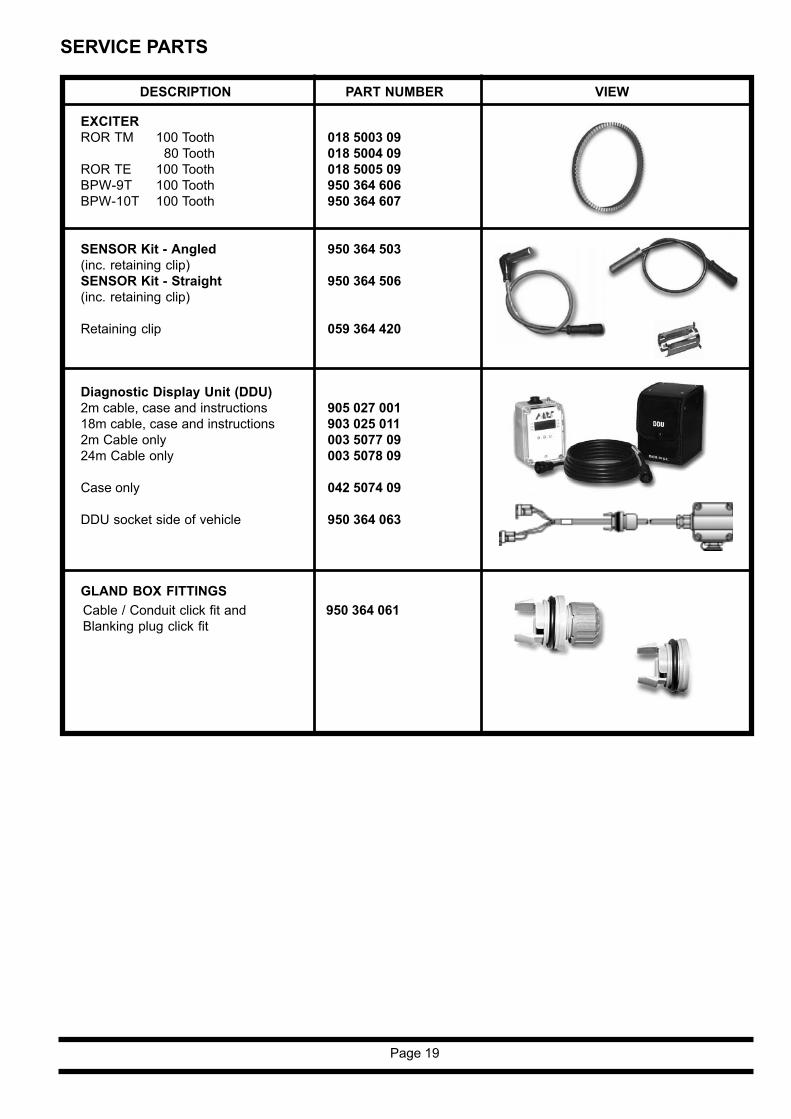
DESCRIPTION PART NUMBER VIEW
SENSOR Kit - Angled(inc. retaining clip)SENSOR Kit - Straight(inc. retaining clip)
Retaining clip
EXCITERROR TM 100 Tooth
80 ToothROR TE 100 ToothBPW-9T 100 ToothBPW-10T 100 Tooth
950 364 503
950 364 506
059 364 420
018 5003 09018 5004 09018 5005 09950 364 606950 364 607
Diagnostic Display Unit (DDU)2m cable, case and instructions18m cable, case and instructions2m Cable only24m Cable only
Case only
DDU socket side of vehicle
905 027 001903 025 011003 5077 09003 5078 09
042 5074 09
950 364 063
GLAND BOX FITTINGSCable / Conduit click fit andBlanking plug click fit
950 364 061

AUSTRIAHaldex Wien Ges.m.b.HViennaTel: + 43 1865 16 40Fax: + 43 1865 16 4027e-mail: [email protected]
BELGIUMHaldex N.V./S.A.Zaventem (Brussels)Tel: + 32 2725 3707Fax: + 32 2752 4099e-mail: [email protected]
BRAZILHaldex do BrazilSão PauloTel: + 55 11 531 4159
+ 5511 531 4999Fax: + 55 11 531 9515e-mail: [email protected]
CHINAHaldex International Trading Co. Ltd.ShanghaiTel: + 86 21 6289 4469Fax: + 86 21 6279 0554e-mail: [email protected]
FRANCEHaldex Europe S.A.Weyersheim (Strasbourg)Tel: + 333 88 68 22 00Fax: + 333 88 68 22 09e-mail: [email protected]
GERMANYHaldex Brake Products G.m.b.HDenkendorf (Stuttgart)Tel: + 49 711 93 49 17 0Fax: + 49 711 93 49 17 40e-mail: [email protected]
Haldex Brake Products G.m.b.HHeidelbergTel: + 49 6221 70 30Fax: + 49 6221 70 34 00e-mail: [email protected]
Innovative Vehicle Technology
For further information:GREAT BRITAINHaldex Ltd.Newton AycliffeTel: + 44 1 325 310 110Fax: + 44 1 325 311 834e-mail: [email protected]
Haldex Brake Products Ltd.RedditchTel: + 44 1527 499 499Fax: + 44 1527 499 500e-mail: [email protected]
POLANDHaldex Sp z o.o.PraszkaTel: + 48 34 350 11 00Fax: + 48 34 350 11 11e-mail: [email protected]
SOUTH KOREAHaldex Korea Ltd.SeoulTel: + 82 2 2636 7545Fax: + 82 2 2636 7548e-mail: [email protected]
SPAINHaldex España S.A.Parets del Valles (Barcelona)Tel: + 34 93 573 1030Fax: + 34 93 573 0728e-mail: [email protected]
SWEDENHaldex Brake Products ABLandskronaTel: + 46 418 47 6000Fax: + 46 418 47 6001e-mail: [email protected]
USAHaldex Brake Products Corp.Kansas CityTel: + 1 816 891 2470Fax: + 1 816 891 9447e-mail: [email protected]
The Haldex Group is a global supplier of proprietaryproducts for trucks, cars and industrial vehicles, withspecial emphasis on performance and safety. TheGroup is organized in Divisions which focus on theirrespective product niche:
Haldex Brake Systems supplies ABSand brake components for heavy vehicle air brakes.
Haldex Barnes Hydraulics supplies gear pumpsand hydraulic systems for power steering and lifting functionson industrial vehicles and trucks.
Haldex Garphyttan Wire supplies specially steel-alloyedwire products mainly for applications in combustion engines.
Haldex Traction Systems supplies 4WD systems for carsand trucks.
Sales companies are established in Europe, North and SouthAmerica and Asia. Production takes place in 9 factories in USA,9 factories in Europe and 1 joint venture in India.The Haldex Group is listed on the Stockholm Stock Exchange.
Company VisionWe use our demonstrated competenceto provide innovative components, systems andservice for trucks, trailers and buses, that lowerlife cycle costs and improve vehicle safety.Haldex wants to become the first choicebusiness partner of commercial vehiclemanufactures world wide in the areas of brakingand suspension control systems with specialemphasis on heavy commercial vehicles.
Total SupportA uniquely wide range of services is availablefrom Haldex. These include expert consultancyfor braking and suspension development, brakecalculations, type approvals and applicationengineering.The aim is accurate specification formanufactures and low cost of owner shipfor the operator.Full aftermarket support includes a Worldwideparts distribution and service network, on-linetechnical advice, field visits and installation/maintenance training held on-site or at Haldexfacilities.
Research andDevelopmentContinual, heavy investment in Research andDevelopment is carried out in response toever increasing commercial, legislative,environmental, performance andtechnological demands.
Quality andProduction StandardsThe very latest production technology ensuresthe very highest quality standards. All produc-tion sites are ISO 9001 approved.


