

Osisense™ XGRadio Frequency Identifi cation System
CatalogJune 2011


3
Contents 0 OsiSense™ XG Radio Frequency Identifi cation System13.56 MHz
Selection guide . . . . . . . . . . . . . . . . . . . . . . . . . . . . . . . . . . . . . . . . . . . . . . . . . . . 4
Introduction, Description b . . . . . . . . . . . . . . . . . . . . . . . . . . . . . . . . . . . . . . . . . . . 7
Specifi cationsb . . . . . . . . . . . . . . . . . . . . . . . . . . . . . . . . . . . . . . . . . . . . . . . . . . . 13
Catalog Numbersb . . . . . . . . . . . . . . . . . . . . . . . . . . . . . . . . . . . . . . . . . . . . . . . . 16
Dimensionsb . . . . . . . . . . . . . . . . . . . . . . . . . . . . . . . . . . . . . . . . . . . . . . . . . . . . 20
Connectionsb . . . . . . . . . . . . . . . . . . . . . . . . . . . . . . . . . . . . . . . . . . . . . . . . . . . . 23
Operating Curvesb . . . . . . . . . . . . . . . . . . . . . . . . . . . . . . . . . . . . . . . . . . . . . . . . 24
Installation Informationb . . . . . . . . . . . . . . . . . . . . . . . . . . . . . . . . . . . . . . . . . . . . 26
1
2
3
4
5
6
7
8
9
10
1
2
3
4
5
6
7
8
9
10
1
2
3
4
5
6
7
8
9

4
8
OsiSense® XGRadio Frequency Identifi cation System13.56 MHz
Applications Numerous and varying applications in the industrial, logistic and building sectors:fl exible production workshops, traceability, access control, etc.
Compact stations, 13.56 MHz Flat form 40 Flat form 80
Dimensions, W x H x D (mm) 40 x 40 x 15 80 x 80 x 26
Protocols Modbus™ RTU and Uni-Telway™
Nominal sensing distance depending on associated tag, mm (in.)
18 to 70 (0.71 to 2.76) 20 to 100 (0.79 to 3.94)
Station type XGCS4901201 XGCS8901201
Page 10/17
Electronic tags
Flat form 40 ISO badge(1)
Disc Flat form 26
Cylindrical
Dimensions, W x H x D (mm)
40 x 40 x 15 54 x 85.5 x 0.8
Ø 30 x 3 Ø 30 x 3 26 x 26 x 13
M18 x 1 x 12
40 x 11
Type of memory EEPROM FeRAM EEPROM FeRAM EEPROM
Memory capacity (bytes) 3,408 13,632 2,048 8,192 32,768 256 112 2,048 256
Nominal sensing distance,mm (in.) (3)
With station XGCS49p
33 (1.30) 30 (1.18) 45 (1.77) 25 (0.98) 25 (0.98) 70 (2.76) 48 (1.89) 45 (1.77) 40 (1.57) 18 (0.71) 30–39 (1.18–1.54 in.)
With station XGCS89p
48 (1.89) 40 (1.57) 65 (2.56) 39 (1.54) 39 (1.54) 100 (3.94) 65 (2.56) 65 (2.56) 55 (2.17) 20 (0.79) 35–46(1.38–1.81 in.)
Time (ms)(4)
Read(2)
9.25 + 0.375 x n
16.25 + 0.375 x n
2 x n 6 +0.25 x n
6 +0.25 x n
12 + 0.825 x n 2 x n 12 + 0.825 x n 12 + 0.825 x n
Write(2)
13 +0.8 x n
20 +0.8 x n
2.4 x n 6 +0.25 x n
6 +0.25 x n
20 +11.8 x n
12 +5.6 x n
2.4 x n 20 +11.8 x n
19 +4.1 x n
20 + 11.8 x n
Tag type XGH B444345
XGH B445345
XGHB440245
XGHB440845
XGHB443245
XGH B90E340
XGH B320345
XGH B320246
XGH B221346
XGH B211345
XGHB411346
Page 16
(1) Customized versions on request.(2) n = number of 16-bit words.(3) Metal mounted: See the sensing distances under “Minimum permissible mounting distances
in a metal structure” on page 10/22.(4) Does not include the network transfer time.
Selection guide
New
0335Q-EN copy.inddversion: 4.0
1
2
3
4
5
6
7
8
9

5
8
Connection boxes Ethernet box Tap-off box Profi bus™ box Ethernet IP splitter box
Protocols Modbus TCP/IP Modbus and Uni-Telway Profi bus-DP Ethernet/IPAssociated compact stations
XGCS49p and XGCS89p
Supply voltage c 24 VdcConnection box type XGSZ33ETH TCSAMT31FP XGSZ33PDP XGSZ33EIP
Page 6
Field expanders Conveying type Universal type
Dimensions, W x H x D (mm) 400 x 23 x 50 250 x 250 x 10Dialogue area, W x H (mm) 380 x 45 230 x 230Associated compact stations XGCS4901201Nominal sensing distance depending on associated tag (mm)
30 to 90 26 to 150
Field expander type XGFEC540 XGFEC2525
Page 7
Portable terminal For 13.56 MHz RFID diagnostics
Function Read/Write operations on electronic tags and diagnostics on compact stationsOperating system Microsoft Windows CE.NET Professional version 4.2Terminal type XGSTP401
Page 10/13
OsiSense XG accessories Cables, adaptors, mounting plates, etc.
Pages 10/14 to 10/16
OsiSense® XGRadio Frequency Identifi cation System13.56 MHz
Selection guide
New
0335Q-EN copy.indd version: 4.0
2
3
4
5
6
7
8
9

6
8
OsiSense® XGRadio Frequency Identifi cation System13.56 MHz
Notes
0335Q-EN copy.inddversion: 4.0
1
2
3
4
5
6
7
8
9

8
7
OsiSense® XGRadio Frequency Identifi cation System13.56 MHz
Operating principle
RFID is a term used for radio frequency identifi cation systems. The frequencies range between 50 kHz and 2.5 GHz. The most widely used is 13.56 MHz.
The OsiSense XG radio frequency identifi cation system allows object traceability, object tracking, and access control functions to be performed.Information is stored in an accessible memory bank using a simple radio frequency link. This memory bank is in the form of an electronic tag, which contains an antenna and an integrated circuit. The tag contains the information associated with the object to which the tag is attached. When a tag passes through the fi eld generated by the smart antenna, it detects the signal and exchanges the read or write data between its memory and the smart antenna. The applications are numerous and include the following:
Logistics: dispatch, receipt, transitb Tracking and sorting of baggageb Automatic tolls b Access controlb
The OsiSense XG radio frequency identifi cation system is also suited to diffi cult environments (humidity, temperature, mechanical shock, vibration, dust, etc.). OsiSense XG Radio Frequency Identifi cation System
The OsiSense XG radio frequency identifi cation system is open to the majority of ISO 18000-3, ISO 15693 and ISO 14443 electronic tags. The XG RFID sysetem integrates Modbus RTU, Uni-Telway, Modbus TCP/IP, and Profi bus-DP, and Ethernet/IP protocols.The OsiSense XG RFID system offer includes:
Two models of 13.56 MHz compact smart antenna (read/write)b Eleven models of 13.56 MHz electronic tagsb One portable RFID diagnostics terminal b Four models of network connection boxesb Two models of patented fi eld expanders (accessories that allow you to adapt the b
shape of the dialog zone between the tag and the compact smart antenna)Connection and mounting accessoriesb
SetupXG RFID compact smart antennas are simple to set up, thanks to the following features:
Integrated RFID and network functionsb No programming b Automatic detection of the RFID electronic tags (read or write)b Automatic setting of the communication parameters (speed, format, parity, b
protocol, etc.) Confi guration of the network address (1 to 15) using the badge included with the b
smart antennaRead/write compatibility with the majority of 13.56 MHz tags on the marketb Low sensitivity to metal environmentsb
InstallationThe XG RFID smart antennas are compact and robust. They can easily be integrated into fl exible manufacturing production lines in the following ways:
quick connection using the M12 connectorb clip-on mountingb
An extensive range of connecting cables and connection boxes allow the OsiSense XG smart antennas to be easily connected to industrial communication networks.
DescriptionXG RFID 13.56 MHz compact smart antennas (1)
XGCS smart antennas allow the reading and writing of 13.56 MHz RFID tags that comply to standards ISO 15693, ISO 14443 A and B, and ISO 18000-3.2 models of XG RFID compact smart antennas are available:
Format C compact smart antenna: XGCS490b pppp: Dimensions (mm): 40 x 40 x 15v Nominal sensing distance: 18–70 mm (0.71–2.76 in.), depending on the v
associated tagFormat D compact smart antenna: XGCS890b pppp: Dimensions (mm): 80 x 80 x 26v Nominal sensing distance: 20–100 mm (0.79–3.94 in.), depending on the v
associated tag
(1) For smart antenna and tag selection according to passing speeds, see page 16 .
Introduction, Description
Compact smart antenna, Flat form 40
Compact smart antenna, Flat form 80
1
2
3
4
5
6
7
8
9

8
8
OsiSense® XG 0
Radio Frequency Identifi cation System13.56 MHz
XG RFID 13.56 MHz compact smart antennas (continued)Functions integrated into compact smart antennas:b XG RFID compact smart
antennas integrate functions that simplify communication among the tags, the smart antennas, and the controller (PLC, PC, etc.). These built-in functions are activated by standard reading/writing of word requests sent by the PLC:
Firmware version:v the smart antenna is interrogated to read its versionReset:v the smart antenna is reinitialized and assumes its factory default
confi guration (network address at 1, transmission speed at 19,200 Bd, parameters deleted)
Init:v the smart antenna is reinitialized and operates as if reconnected to the supply (address unchanged, transmission speed unchanged, parameters deleted)
Sleep mode:v the transmission of the electromagnetic fi eld of the smart antenna is only activated on its receipt of a read or write instruction. This mode reduces the power consumption of the smart antenna and enables the suppression of interference when the smart antennas are close to each other
Auto Read/Write:v This mode enables the smart antenna to automatically execute up to 10 read or write instructions (up to 128 write words and up to 126 read words) in a tag as soon as it enters the dialog zoneXG RFID electronic tags (1)XGHB electronic tags offer the following advantages:
fast access to the data b wide range of memory capacities b security of access to the contents b operation without battery b positioning fl exibility b protection suited to the environmental conditionsb
The nominal transmission distance is 18–100 mm ( 0.70–3.93 in.) depending on the model of the tag and the associated compact smart antenna.Portable 13.56 MHz RFID diagnostics terminal
The portable terminal XGSTP401 is designed for use in industrial applications. Its rugged structure combined with its numerous functions make it suitable for applications in diffi cult environments. It operates on Microsoft® Windows® CE.NET Professional version 4.2 operating system. The 13.56 MHz RFID function and OsiSense XG RFID system software installed on the portable terminal allow maintenance operations to be performed on the electronic tags and compact smart antennas.Transfer of data to a PC is made via an RS-232 communication port.The portable terminal XGSTP401 comprises a:1 CF (Compact Flash) format expansion connector2 Color touchscreen3 Keypad (45 keys)4 RS-232 portThe following accessories are included with the terminal:
PC connecting cable- OsiSense XG RFID system software (installed)- battery, universal battery charger, 3 styluses, protective cover- user guide-
Field expander Field expanders are accessories designed to operate with the XG RFID smart antennas. They allow you to adapt the shape of the dialog fi eld of XGCS4901201 smart antennas to conveying/handling applications. The concept is a connection-free induction link between the smart antenna and the fi eld expander. Two standard models are available:
The conveyor model b XGFEC540 detects ISO 15693 tags on a narrow strip covering the width of the conveyor (mounted between two rollers of the conveyor)
Dimensions (mm): 400 x 23 x 50v Nominal sensing distance: 30–90 mm (1.18–3.54 in.) depending on the v
associated tagThe universal model b XGFEC2525 increases the detection area and distance of
ISO 15693 tags, which also permits higher passing speeds of the tagsDimensions: 250 x 250 x 10v Nominal sensing distance: 26–150 mm (1.02–5.90 in.) depending on the v
associated tagRead/write compatibility with the majority of the 13.56 MHz/ISO 15693 tags on the b
market(NOTE: These accessories are not compatible with ISO 14443 tags)(1) For smart antenna and tag selection according to passing speeds, see page 16 .
Description (continued)
2
3
4
1
Electronic tags
Portable diagnostics terminal
Field expanders
1
2
3
4
5
6
7
8
9
8
9
Description (continued) OsiSense® XG 0
Radio Frequency Identifi cation System13.56 MHz
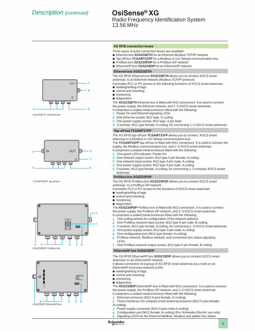
XG RFID connection boxes
Three types of quick connection boxes are available:Ethernet box b XGSZ33ETH for an Ethernet Modbus TCP/IP networkTap-off box b TCSAMT31FP for a Modbus or Uni-Telway communication bus Profi bus box b XGSZ33PDP for a Profi bus-DP networkEthernet/IP box b XGSZ33EIP for an Ethernet/IP network
Ethernet box XGSZ33ETHThe XG RFID Ethernet box XGSZ33ETH allows you to connect XGCS smart antennas to an Ethernet network (Modbus TCP/IP protocol).It provides PLC or PC access to the following functions of XGCS smart antennas:
reading/writing of tags b control and checkingb monitoringb diagnostics b
The XGSZ33ETH Ethernet box is fi tted with M12 connectors. It is used to connect the power supply, the Ethernet network, and 1–3 XGCS smart antennas.It comprises a sealed metal enclosure fi tted with the following:1 Power On and Ethernet signaling LEDs2 One Ethernet socket, M12 type, D coding3 One power supply socket, M12 type, 4-pin male4 3 sockets, M12 type female, A coding, for connecting 1–3 XGCS smart antennas.
Tap-off box TCSAMT31FP The XG RFID tap-off box TCSAMT31FP allows you to connect XGCS smart antennas to a Modbus or Uni-Telway communication bus.The TCSAMT31FP tap-off box is fi tted with M12 connectors. It is used to connect the supply, the Modbus communication bus, and 1–3 XGCS smart antennas.It comprises a sealed metal enclosure fi tted with the following:1 One green LED indicator: Power On2 One network output socket, M12 type 5-pin female, A coding3 One network input socket, M12 type 5-pin male, A coding4 One power supply socket, M12 type 4-pin male, A coding5 3 sockets, M12 type female, A coding, for connecting 1–3 compact XGCS smart
antennas Profi bus box XGSZ33PDP
The XG RFID Profi bus box XGSZ33PDP allows you to connect XGCS smart antennas to a Profi bus-DP network.It provides PLC or PC access to the functions of XGCS smart antennas:
reading/writing of tagsb control and checkingb monitoringb diagnosticsb
The XGSZ33PDP Profi bus box is fi tted with M12 connectors. It is used to connect the power supply, the Profi bus-DP network, and 1–3 XGCS smart antennas.It comprises a sealed metal enclosure fi tted with the following:1 Two coding wheels for confi guration of the network address2 One Profi bus network input socket, M12 type 5-pin male, B coding3 3 sockets, M12 type female, A coding, for connecting 1–3 XGCS smart antennas 4 One power supply socket, M12 type 4-pin male, A coding5 One confi guration port (M12 type female, A coding)6 Profi bus network, Modbus network, and connection box status signaling LEDs7 One Profi bus network output socket, M12 type 5-pin female, B coding.
Ethernet/IP box XGSZ33EIP
The XG RFID Ethernet/IP box XGSZ33EIP allows you to connect XGCS smart antennas to am Ethernet/IP network.It allows connection of a group of XG RFID smart antennas as a node on an Ethernet/IP local area network (LAN)
reading/writing of tagsb control and checkingb monitoringb diagnosticsb
The XGSZ33EIP Ethernet/IP box is fi tted with M12 connectors. It is used to connect the power supply, the Profi bus-DP network, and 1–3 XGCS smart antennas.It comprises a sealed metal enclosure fi tted with the following:1 Ethernet connector (M12 4-pins female, D-coding)2 Three OsiSense XG compact smart antennaconnector (M12 5-pins female, A-coding) 3 Power supply connector (M12 4-pins male A-coding)4 Confi guration port (M12 female, A-coding) (For Schneider Electric use only)5 Signaling LEDS for the Ethernet fi eldbus, Modbus and splitter box status
1
2
4 3
2
4
3
5
1
IN OUT
1
7
32 4 5 6
XGSZ33ETH Ethernet box
TCSAMT31FP tap-off box
XGSZ33PDP Profi bus box
XGSZ33EIP Ethernet/IP box21 3 4 5
1 MODULE STATUS2 NETWORK STATUS3 LINK4 ACTIVITY5 MODBUS6 DEVICE STATUS
@ IP
1
2
3
4
5
6
7
8
9

8
10
Ethernet switch
Mounting example for Modbus™ network
Maximum length of busThe maximum length of the bus (L + L1 + l4) depends on the speed of the network:
9,600 bd: 1000 m- 19,200 bd: 500 m-
Maximum length of tap-offs:l1, l2, and l3: 10 m.
Example of connection to a Schneider Electric PLCDirect connection Connection via a TSXSCA62
Example of a connection on an Ethernet Modbus™ TCP/IP networkPremium
M340
XGSZ33ETH
XGSZ33ETH
XGSZ09Lp
XGS Z09Lp
XGCS49/89XGCS49/89
ABL8
ABL8
TCSMCN1M1F
TCSCTN011M11FTCSECL1M3MpS2
TCSECL1M3MpS2
XGCS49/89
24 VDC24 VDC
The number of smart antennas connected to each box can be increased by using the M12 T-connector (catalog number TCSCTN011M11F).To maintain high-performance operation, we recommend that a maximum of 8 compact smart antennas be connected (the Ethernet box has eight communication ports and sockets that can be simultaneously open on TCP/IP). In cases where the I/O scanning function is used (which requires an additional communication port), do not connect more than seven smart antennas.The total length of the smart antenna side network for XGCS smart antennas (XGCS49 and XGCS89) is limited to 160 m.
Description (continued) OsiSense® XGRadio Frequency Identifi cation System13.56 MHz
c 24 Vdc
TSCAMT31FP
XGSZ09Lp
TSCMCN1F9M2P
TSCMCN1M1Fp
XGCS49/89XGCS49/89
IN OUT
PLC
c 24 Vdc
TSCAMT31FP
XGSZ09LpTSCMCN1M1Fp
XGCS49/89XGCS49/89
TCSMCN1FQM2
TSXCSA62TSXCSAp00
IN OUT
PLC
l2l1
L
L1
24 Vdc
l4l3
24 Vdc
Premium
TSCAMT31FP TSCAMT31FP
XGSZ09Lp XGSZ09Lp
XGCS49/89XGCS49/89 XGCS49/89
IN OUT IN OUT
1
2
3
4
5
6
7
8
9

8
11
Example of a mixed IP 20 and IP 67 connection on an Ethernet Modbus™ TCP/IP networkTCSECL1M1M pS2
TCSESU051F0
TCSECL1M1M pS2TCSEAAF11F13F00
TCS ECL1M3MpS2
c 24 Vdc c 24 Vdc c 24 Vdc XGSZ09L p
XGSZ33ETH XGSZ33ETH XGSZ33ETHTCSMCN1M1Fp
XGCS49/89 XGCS49/89
XGCS49/89
ABL8
IP 67 IP 20
Example of a connection to a Magelis™ terminal
c 24 Vdc
TCSMCN1F2
XBTNXGCS49/89pp
Cable TCSMCN1F2 connections
Scheme Contact Signal Wire color
21
35
4
1 Drain (Modbus-SHLD)
–
2 c 24 Vdc Red3 0 V Modbus-GND Black4 D0 White
5 D1 Blue
1) Magelis™ terminal supply connector (included with the Magelis terminal).
Example of a connection on an Ethernet/IP networkPLC
Ethernetswitch
XGSZ33EIP
XGSZ33EIP
XGSZ09Lp
XGSZ09Lp
XGCS49/89XGCS49/89
ABL8
ABL8
TCSMCN1M1F
TCSCTN011M11FTCSECL1M3MpS2
TCSECL1M3MpS2
XGCS49/89
24 VDC24 VDC
The number of smart antennas connected to each box can be increased by using the M12 T-connector (catalog number TCSCTN011M11F). To maintain high-performance operation, we recommend that a maximum of 8 compact smart antennas be connected. The total length of a smart antenna side network for XGCS smart antennas (XGCS49 and XGC89) is limited to 160 m.
Description (continued) OsiSense® XGRadio Frequency Identifi cation System13.56 MHz
PLC
SUB-D 25-pin male
Supply connector (1)
ConneXium™ switch
1
2
3
4
5
6
7
8
9

8
12
Description (continued) OsiSense® XGRadio Frequency Identifi cation System13.56 MHz
Example of an architecture in a Profi bus network
Quantum PLC
Other master
ATV58E
Premium PLC
FTB1DP
XGCS49/89
ABL8
TCSMCN1M1FTCSCTN011M11F
XGCS49/89
XGSZ09Lp
XGSZ33PDP XGSZ33PDP
FTXDP1203
Example of a connection on a Twido™ PLC Example of a connection to a PC
XZCP1541Lp
ABL8
Twido
TCSCTN011M11F
TCSMCN1Fp
XGCS49/89 XGCS49/89
XGS Z24
5 2 3TCSMCN1Fp
D1
Drain (SHLD)
D0
c 24 Vdc0 V
XGCS49/89
0 V
5 4 3 2
9 8 7 6
1
ABL8
c 24 Vdc
Power supply cable connections TCSMCN1Fp cable connectionsXZCP1541Lp Power supply ABL8 TCSMCN1Fp Twido™ PLC
Scheme Contact Signal Wire color
Terminal Scheme Contact Signal Wire color Terminal Scheme
21
34
1 NC Brown – 21
35
4
1 Drain (SHLD)
– –
A B SG
2 c 24 VdcWhite c 24 Vdc 2 c 24 Vdc Red –3 0 V GND Blue 0 V GND 3 0 V GND Black SG4 NC Black – 4 D0 White B
5 D1 Blue A
The compact smart antennas can be directly connected to the Modbus port of a PLC. Up to 15 compact smart antennas can be linked to the RS-485 port using T-connectors. (In cases where the length of the network exceeds 100 m, fi t a line terminator, catalog number FTXCNTL12.) This cabling system is specifi c to the OsiSense™ XG RFID System (powered network). No other Modbus slave equipment can be connected to it.
SUB-D 9-pin female
Pro
fi bus
-DP
bus
1
2
3
4
5
6
7
8
9

8
13
OsiSense®XG 0
Radio Frequency Identifi cation System13.56 MHz
Specifi cations of XG RFID compact smart antennasSmart antenna type XGCS4901201 XGCS8901201
Certifi cations UL, FCC part 15cConformity to standards e, EN 301489-1, EN 301489-3, ETS 300330-1 and ETS 300330-2Ambient air temperature For operation °C (°F) –25 to +70 (–13 to +158)
For storage °C (°F) –40 to +85 (–40 to +185)Degree of protection Conforming to IEC 60529 IP 67Vibration resistance Conforming to EN 60068.2.27 2 mm from 5–29.5 Hz / 7 gn from 29.5–150 HzShock resistance Conforming to EN 60068.2.6 30 g/11 ms
Conforming to EN 50102 Degree IK 02Resistance to interference Conforming to IEC 61000 Resistance to electrostatic discharge, radiated electromagnetic fi elds, fast transients,
electrical surges, conducted and induced interference and network frequency magnetic fi elds.
Dimensions, W x H x D mm Flat form 40: 40 x 40 x 15 Flat form 80: 80 x 80 x 26RFID frequency MHz 13.56Type of associated tag ISO 15693 and ISO 14443 standard tags.
Automatic detection of the type of tagCompatible RFID microchip examples Texas (Tag-it HFI); Philips (SL2, SL1, Ultralight, Std 1K/2K, Desfi re; STM (CRIX4K);
INSIDE ( micropass)Nominal sensing distance Depending on associated tag mm (in.) 18–70 (0.71–2.76) 20–100 (0.79–3.94)Nominal supply voltage Vdc c 24 PELV (Protective Extra Low Voltage)Supply voltage limits (including ripple) Vdc c 19.2–29Consumption mA < 60Serial links Type RS-485
Protocol Modbus RTU or Uni-TelwaySpeed Bd 9,600–115,200 (automatic detection)
Display 1 dual color LED for the communication network:Modbus/Uni-Telway1 dual color LED for the RFID communication(Presence of tag / Smart antenna/tag dialog)
Connections M12, 5-pin male, shielded connector. Only for connection to the communication network and the supply.
Tightening torque Screws Nm < 1 < 3
Specifi cations of portable 13.56 MHz RFID diagnostics terminal
Conformity to standards e, FCC class A, Part 15225
Ambient air temperature For operation °C (°F) 0 to +50 (32 to +122)
For storage °C (°F) –25 to +55 (–13 to +131)
Relative humidity RH 5–95% without condensation
Degree of protection IP 65
Supply voltage 7.2 V NiMH type rechargeable battery (included with terminal)External: c 11-18 Vdc
Operating time 4 hours continuous operation (tag dialog)
Operating system Microsoft Windows CE.NET Professional version 4.2
Processor Intel Xscale® PXA255 CPU, 400 MHz
Memory RAM SDRAM 64 Mb (16 Mb reserved for operating system)
Storage Internal compact Flash: 512 Mb standard + Slot for compact Flash card (such as memory, wi-fi , Ethernet, or Bluetooth)
Display Screen Color touchscreen: 72 mm x 54 mm, QVGA TFT
Resolution 320 x 240 pixels
Keypad 45 booted keys
Signaling 5 LEDs + 1 charging LED
Specifi cations
1
2
3
4
5
6
7
8
9

8
14
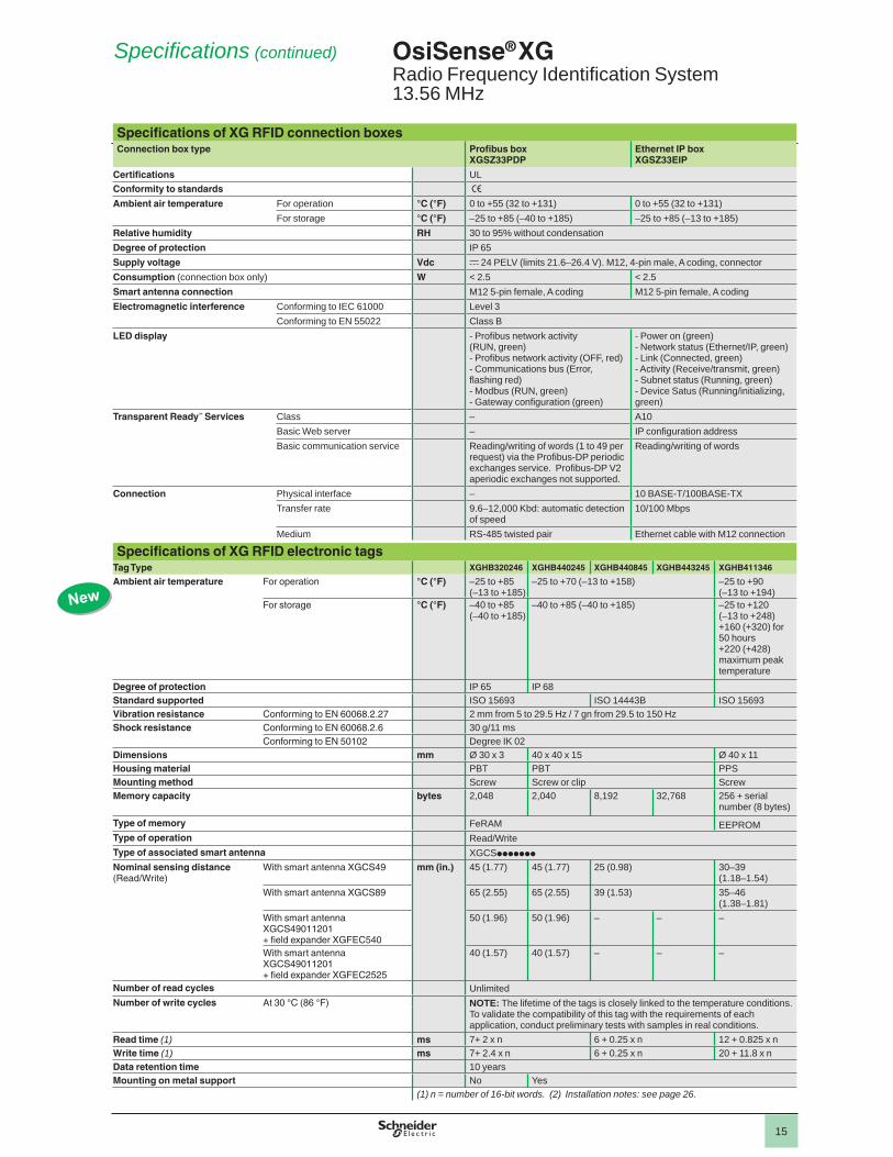
Specifi cations of XG RFID connection boxesConnection box type Tap-off box
TCSAMT31FPEthernet box XGSZ33ETH
Certifi cations ULConformity to standards eAmbient air temperature For operation °C (°F) –25 to +55 (–13 to +131) 0 to +70 (32 to +158)
For storage °C (°F) –40 to +85 (–40 to +185) –40 to +85 (–40 to +185)Relative humidity RH 30 to 95% without condensationDegree of protection IP 65Supply voltage Vdc c 24 PELV (limits 19.2–29 V). M12, 4-pin male,
A coding, connectorConsumption (connection box only) W – < 1Smart antenna connection M12 5-pin female, A coding, connectorElectromagnetic interference Conforming to IEC 61000 Level 3
Conforming to EN 55022 Class BLED display Power on (green) - Ethernet network activity (RUN,
green)- Collision detection (COL, red)- Diagnostics (STS, yellow)- Error (Err, red)- Power on (green)
Transparent Ready™ Services Class – A10Basic Web server – IP confi guration addressBasic communication service – Modbus messaging
(reading/writing of words: 1 to 123 words per request)
Connection Physical interface – 10 BASE-T/100BASE-TX Transfer rate – 10/100 MbpsMedium – Ethernet cable with M12 connection
Specifi cations of XG RFID electronic tagsTag Type XGHB444345 XGHB445345 XGHB90E340 XGHB320345 XGHB221346 XGHB211345
Ambient air temperature For operation °C (°F) –25 to +70 (–13 to +158) –25 to +50(13 to +122)
–25 to +70 (–13 to +158)
For storage °C (°F) –40 to +85 (–40 to +185) –40 to +55(–40 to +131)
–40 to +85 (–40 to +185)
Degree of protection IP 68 IP 65 IP 68Standard supported ISO 14443 ISO 15693Vibration resistance Conforming to EN 60068.2.27 2 mm from 5 to 29.5 Hz / 7 gn from 29.5 to 150 HzShock resistance Conforming to EN 60068.2.6 30 g/11 ms
Conforming to EN 50102 Degree IK 02Dimensions mm 40 x 40 x 15 40 x 40 x 15 54 x 85.5 x 1 Ø 30 x 3 26 x 26 x 13 M18 x 1 x 12Housing material PBT PVC PVC PBT PBTMounting method Screw or clip – Screw Screw or clip Screw inMemory capacity bytes 3,408 13,632 256 112 256 Type of memory EEPROMType of operation Read/WriteType of associated smart antenna XGCSppppppp
Nominal sensing distance (Read/Write)
With smart antenna XGCS49 mm (in.)
33 (1.30) 30 (1.18) 70 (2.76) 48 (1.89) 40 (1.57) 18 (0.71)With smart antenna XGCS89 48 (1.89) 40 (1.57) 100 (3.94) 65 (2.56) 55 (2.17) 20 (0.79)With smart antenna XGCS49011201+ fi eld expander XGFEC540
– – 90 (3.54) 42 (1.65) – –
With smart antenna XGCS49011201+ fi eld expander XGFEC2525
– – 150 (5.91) 80 (3.15) 42 (1.65) –
Number of read cycles UnlimitedNumber of write cycles Minimum 100,000 per data bit throughout the temperature range
At 30 °C (86 °F) 2.5 million (typical value)Read time ms 9.25 +
0.375 x n (1)16.25 +0.375 x n (1)
12 + 0.825 x n (1)
Write time ms 13 +0.8 x n (1)
20 +0.8 x n (1)
20 +11.8 x n (1)
12 +5.6 x n (1)
20 +11.8 x n (1)
19 +4.1 x n (1)
Data retention time 10 yearsMounting on metal support Yes (2) No Yes (2) No
(1) n = number of 16-bit words.(2) Installation information: see page 26 .
OsiSense® XG 0
Radio Frequency Identifi cation System13.56 MHz
Specifi cations (continued)
1
2
3
4
5
6
7
8
9
8
15
OsiSense®XG 0
Radio Frequency Identifi cation System13.56 MHz
Specifi cations of XG RFID connection boxesConnection box type Profi bus box
XGSZ33PDPEthernet IP boxXGSZ33EIP
Certifi cations ULConformity to standards eAmbient air temperature For operation °C (°F) 0 to +55 (32 to +131) 0 to +55 (32 to +131)
For storage °C (°F) –25 to +85 (–40 to +185) –25 to +85 (–13 to +185)Relative humidity RH 30 to 95% without condensationDegree of protection IP 65Supply voltage Vdc c 24 PELV (limits 21.6–26.4 V). M12, 4-pin male, A coding, connectorConsumption (connection box only) W < 2.5 < 2.5Smart antenna connection M12 5-pin female, A coding M12 5-pin female, A codingElectromagnetic interference Conforming to IEC 61000 Level 3
Conforming to EN 55022 Class BLED display - Profi bus network activity
(RUN, green)- Profi bus network activity (OFF, red)- Communications bus (Error, fl ashing red)- Modbus (RUN, green)- Gateway confi guration (green)
- Power on (green)- Network status (Ethernet/IP, green)- Link (Connected, green)- Activity (Receive/transmit, green)- Subnet status (Running, green)- Device Satus (Running/initializing, green)
Transparent Ready™ Services Class – A10Basic Web server – IP confi guration addressBasic communication service Reading/writing of words (1 to 49 per
request) via the Profi bus-DP periodic exchanges service. Profi bus-DP V2 aperiodic exchanges not supported.
Reading/writing of words
Connection Physical interface – 10 BASE-T/100BASE-TX Transfer rate 9.6–12,000 Kbd: automatic detection
of speed10/100 Mbps
Medium RS-485 twisted pair Ethernet cable with M12 connection
Specifi cations of XG RFID electronic tagsTag Type XGHB320246 XGHB440245 XGHB440845 XGHB443245 XGHB411346
Ambient air temperature For operation °C (°F) –25 to +85 (–13 to +185)
–25 to +70 (–13 to +158) –25 to +90 (–13 to +194)
For storage °C (°F) –40 to +85 (–40 to +185)
–40 to +85 (–40 to +185) –25 to +120 (–13 to +248)+160 (+320) for 50 hours+220 (+428) maximum peak temperature
Degree of protection IP 65 IP 68Standard supported ISO 15693 ISO 14443B ISO 15693Vibration resistance Conforming to EN 60068.2.27 2 mm from 5 to 29.5 Hz / 7 gn from 29.5 to 150 HzShock resistance Conforming to EN 60068.2.6 30 g/11 ms
Conforming to EN 50102 Degree IK 02Dimensions mm Ø 30 x 3 40 x 40 x 15 Ø 40 x 11Housing material PBT PBT PPSMounting method Screw Screw or clip ScrewMemory capacity bytes 2,048 2,040 8,192 32,768 256 + serial
number (8 bytes)
Type of memory FeRAM EEPROMType of operation Read/WriteType of associated smart antenna XGCSppppppp
Nominal sensing distance (Read/Write)
With smart antenna XGCS49 mm (in.) 45 (1.77) 45 (1.77) 25 (0.98) 30–39 (1.18–1.54)
With smart antenna XGCS89 65 (2.55) 65 (2.55) 39 (1.53) 35–46 (1.38–1.81)
With smart antenna XGCS49011201+ fi eld expander XGFEC540
50 (1.96) 50 (1.96) – – –
With smart antenna XGCS49011201+ fi eld expander XGFEC2525
40 (1.57) 40 (1.57) – – –
Number of read cycles UnlimitedNumber of write cycles At 30 °C (86 °F) NOTE: The lifetime of the tags is closely linked to the temperature conditions.
To validate the compatibility of this tag with the requirements of each application, conduct preliminary tests with samples in real conditions.
Read time (1) ms 7+ 2 x n 6 + 0.25 x n 12 + 0.825 x nWrite time (1) ms 7+ 2.4 x n 6 + 0.25 x n 20 + 11.8 x nData retention time 10 yearsMounting on metal support No Yes
(1) n = number of 16-bit words. (2) Installation notes: see page 26 .
Specifi cations (continued)
New
1
2
3
4
5
6
7
8
9

8
16
XGHB411346
OsiSense® XG 0
Radio Frequency Identifi cation System13.56 MHz
Compact smart antennas, 13.56 MHzDescription Protocols Dimensions
mmCatalog number Weight
kg (lb)Compact smart antennaFlat form 40 (1)M12 male connector on fl ying lead
Modbus RTU and Uni-Telway
40 x 40 x 15 XGCS4901201 0.057 (0.126)
Compact smart antennaFlat form 80 (1)M12 male connector on fl ying lead
Modbus RTU and Uni-Telway
80 x 80 x 26 XGCS8901201 0.257 (0.567)
Electronic tagsTag type Nominal sensing dist. Dimensions
mmSold in lots of
Unit catalog number
Weightkg (lb)XGCS49p XGCS89p
Flat form 40 3 K bytesEEPROM
33 mm(1.30 in.)
48 mm (1.89 in.)
40 x 40 x 15 – XGHB444345 0.031 (0.068)
Flat form 4013 K bytesEEPROM
30 mm(1.80 in.)
40 mm(1.57 in.)
40 x 40 x 15 – XGHB445345 0.031 (0.068)
Flat form 402 K bytesFeRAM
45 mm(1.77 in.)(2)
65 mm(2.56 in.)(2)
40 x 40 x 15 – XGHB440245 0.031 (0.068)
Flat form 408 K bytesFeRAM
25 mm (0.98 in.)(5)
39 mm (1.54 in.)(5)
40 x 40 x 15 – XGHB440845 0.031 (0.068)
Flat form 4032 K bytesFeRAM
25 mm (0.98 in.)(5)
39 mm (1.54 in.)(5)
40 x 40 x 15 – XGHB443245 0.031 (0.068)
ISO badge (3) 256 bytesEEPROM
70 mm(2.76 in.)
100 mm(3.94 in.)
54 x 85.5 x 1 10 XGHB90E340 0.005 (0.011)
Disc112 bytesEEPROM
48 mm(1.89 in.)
65 mm(2.56 in.)
Ø 30 x 3 5 XGHB320345 0.005 (0.011)
Disc2 K bytesFeRAM
45 mm(1.77 in.)
65 mm(2.56 in.)
Ø 30 x 3 5 XGHB320246 0.005 (0.011)
Flat form 26256 bytesEEPROM
40 mm(1.57 in.)
55 mm(2.17 in.)
26 x 26 x 13 1 XGHB221346 0.025 (0.055)
Cylindrical256 bytesEEPROM
18 mm(0.71 in.)
20 mm(0.79 in.)
M18 x 1 x 12 5 XGHB211345 0.020 (0.044)
Cylindrical256 bytesEEPROM
30–39 (1.18–1.54 in.)
35–46(1.38–1.81 in.)
M40 x 11 – XGHB411346 0.025(0.055)
Connection boxesDescription For use with Supply
voltageCatalog number Weight
kg (lb)Ethernet box3-channelIntegrated Ethernet port (10/100 Mbps) Modbus TCP/IP protocolClass A10
Compact smart antennasXGCS49p and XGCS89p
c 24 Vdc XGSZ33ETH 1.060 (2.337)
Tap-off box 3-channel Modbus and Uni-Telway
Compact smart antennasXGCS49p and XGCS89p
c 24 Vdc TCSAMT31FP 1.060 (2.337)
Profi bus box3-channel Profi bus-DP protocol (4)
Compact smart antennasXGCS49p and XGCS89p
c 24 Vdc XGSZ33PDP 1.060 (2.337)
Ethernet/IP box3-channelIntegrated Ethernet port (10/100 Mbps)
Compact smart antennasXGCS49p and XGCS89p
c 24 Vdc XGSZ33EIP 1.060 (2.337)
1059
09
XGCS4901201
XGHB44p345
1059
10
1059
14
XGHB90E340
XGHB221346
1059
11
1059
12
XGHB211345
Catalog Numbers
TCSAMT31FP
1059
15
XGHB320345
1059
13
(1) Confi guration badge XGSZCNF01 included with smart antenna—installation guide must be orderedseparately (catalog number DIA4ED3051001).(2) Metal mounted: 30 mm (1.18 in.) with XGCS49p; 45 mm (1.77 in.) with XGCS89p.(3) Customized versions on request.(4) Download GSD confi guration fi le (SE100BBB.gsd) from www.Schneider-Electric.com(Products and services/Automation and control/Detection/RFID).(5) Metal mounted: 20 mm (0.78 in.) with XGCS49p; 28 mm (1.10 in.) with XGCS89p.
1
2
3
4
5
6
7
8
9

8
17
OsiSense® XG 0 Radio Frequency Identifi cation System13.56 MHz
Field expanders (3)Description Nominal sensing
distanceFor use with Catalog number Weight
kg (lb)Conveying type fi eld expanderDimensions (mm)400 x 23 x 50 (1)
30–90 mm (1.18–3.54 in.)depending on tag used (only ISO 15693)
Smart antennaXGCS4901201TagsXGHB90E340XGHB320345XGHB221346
XGFEC540 0.640 (1.411)
Universal type fi eld expanderDimensions (mm)250 x 250 x 10 (1)
26–150 mm (1.02–5.91 in.)depending on tag used(only ISO 15693)
Smart antennaXGCS4901201TagsXGHB90E340XGHB320345
XGFEC2525 0.565 (1.466)
Terminal and accessoriesDescription Application Catalog number Weight
kg (lb)Portable 13.56 MHz RFID diagnostics terminal (2)
Read/write operations on electronic tags and diagnostics on compact smart antennasOperating system:Microsoft Windows CE.NET Professional version 4.2
XGSTP401 0.943 (2.079)
Battery pack charger Portable terminal XGSTP41CH 0.675 (1.488)
Battery, 7.2 V NiMH Portable terminal XGSTP41BA 0.168 (0.370)
Compact Flash memory expansion
Portable terminalCapacity = 128 Mb
XBTZGM128 0.050 (0.110)
Confi guration badge (replacement)Description Application Catalog number Weight
kg (lb)Badge Confi guration of smart antenna
addressesXGSZCNF01 0.005
(0.011)
DocumentationDescription Catalog number Weight
kg (lb)XG RFID compact smart antennas guide DIA4ED3051001 0.130
(0.029)
(1) For other dimensions, please consult your local sales offi ce.(2) Includes OsiSense™ XG RFID system software (installed), universal battery charger, PC
connecting cable, 3 styluses, protective cover, battery, and user guide.(3) For custom shape fi eld expanders, contact the Sensor Competency Center at 1-800-435-2121.
XGSTP401
1059
18
XGSTP41BA
1059
20
1059
21
XGSZCNF01
Catalog Numbers (continued)
XGFEC540
XGFEC2525
1
2
3
4
5
6
7
8
9

8
18
OsiSense® XG 0
Radio Frequency Identifi cation System13.56 MHz
Modbus™ network connection accessoriesDescription Application Length
mCatalog number Weight
kg (lbs)
Modbus shielded connecting cable, black, IP 67M12 connectors, male/female, A coding (1)
RS-485 connection between a compact smart antenna and a tap-off box TCSAMT31FP or between 2 tap-off boxes
1 TCSMCN1M1F1 0.080 (0.176)2 TCSMCN1M1F2 0.115 (0.254)5 TCSMCN1M1F5 0.270 (0.595)10 TCSMCN1M1F10 0.520 (1.146)
Modbus shielded pre-wired M12 connector, IP 67, female/bare wires, A coding (1)
Connection between tap-off box TCSAMT31FP and Modbus/Uni-Telway network (TSXSCA50)
2 TCSMCN1F2 0.115 (0.254)5 TCSMCN1F5 0.270 (0.595)10 TCSMCN1F10 0.520 (1.146)
Modbus shielded connecting cable, black, M12/SUB-D15, A coding
Connection between tap-off box TCS AMT31FP and Modbus/Uni-Telway network (TSXSCA62)
2 TCSMCN1FQM2 0.270 (0.595)
Modbus shielded connecting cable, black, M12/Mini-DIN 8-way, A coding
Modbus connection between tap-off box TCSAMT31FP and a PLC (such as Twido™)
2 TCSMCN1F9M2P 0.350 (0.772)
Modbus SL serial link cable (Shielded dual twisted pair RS-485 main cables)
Modbus SL serial link 100 TSXCSA100 5.680 (12.522)
200 TSXCSA200 10.920 (24.074)
500 TSXCSA500 30.000 (66.139)
Ethernet connection accessoriesEthernet connection accessories for IP 67 switchDescription End fi ttings Length
mCatalog number Weight
kg (lbs)
Copper connecting cables, straight
1 x IP 67 M12 4-pin connector and 1 x RJ45 connector
1 TCSEL1F3M12S2D –3 TCSEL1F3M13S2D –10 TCSEL1F3M110S2D –25 TCSEL1F3M125S2D –40 TCSEL1F3M140S2D –
2 x IP 67 M12 4-pin connectors
1 TCSEL1F1F12S2D –3 TCSEL1F1F13S2D –10 TCSEL1F1F110S2D –25 TCSEL1F1F125S2D –40 TCSEL1F1F140S2D –
M12 Ethernet switchIP 67, ConneXium™ (2)
– – TCSESU051F0 0.210 (0.463)
M12 female/RJ45 adapter
Ethernet connection – TCSEAAF11F13F00 –
Do-It-Yourself Ethernet copper cable and connectorsThe Do-It-Yourself ConneXium™ Ethernet system allows Ethernet copper connecting cables to be prepared on-site in the required length. The cables are intended for connection to the Ethernet 10/100 Mbps network. The maximum length of the connecting cables made in this way is 80 m. The cabling can be quickly assembled using a knife and ordinary wire cutters—no special tools required.Description Specifi cations Length
mCatalog number Weight
kg (lbs)Ethernet copper cable2 x 24 AWG shielded dual twisted pairs
Conforms to applicable standards and approvals
300 TCSECN300R2 –
RJ45 connector Conforms to EIA/TIA-568-D
– TCSEK3MDS –
M12 connector Conforms to IEC 60176-2-101
– TCSEK1MDRS –
Power suppliesDescription Output
voltageNominal power
Nominal current
Catalog number Weight
Vdc W A kg (lbs)Regulated power supply 100/240 Vac
24 7 0.3 ABL8MEM24003 0.180 (0.397)
30 1.2 ABL8MEM24012 0.520 (1.146)
(1) Holder for identifi cation legend included with product.(2) Other ConneXium™ connection accessories:
refer to www.Schneider-Electric.com.
TCSMCN1FQM2
1059
25
TCSMCN1F9M2P
1059
27
Catalog Numbers (continued)
1064
10
ABL8MEM24003
1
2
3
4
5
6
7
8
9

8
19
OsiSense® XG 0
Radio Frequency Identifi cation System13.56 MHz
Profi bus-DP connection accessoriesDescription Composition Type Length
mCatalog number Weight
kg (lb)
Connecting cable for connection between Profi bus box XGSZ33DP and Profi bus-DP network
Fitted with 2 x M12 5-pin connectors
Straight 0.3 FTXDP1203 0.040 (0.088)0.6 FTXDP1206 0.070 (0.154)1 FTXDP1210 0.100 (0.220)2 FTXDP1220 0.160 (0.353)3 FTXDP1230 0.220 (0.485)5 FTXDP1250 0.430 (0.948)
Elbowed 0.3 FTXDP3203 0.040 (0.088)0.6 FTXDP3206 0.070 (0.154)1 FTXDP3210 0.100 (0.220)2 FTXDP3220 0.160 (0.353)3 FTXDP3230 0.220 (0.485)5 FTXDP3250 0.430 (0.948)
M12 connector, 5-pin male, B coding – FTXDP12M5 0.050 (0.110)M12 connector, 5-pin female, B coding – FTXDP12F5 0.050 (0.110)Network terminator, M12 connector – FTXDPTL12 0.010 (0.022)Cable without end fi ttings 100 TSXPBSCA100 –
400 TSXPBSCA400 –
Other connection accessoriesDescription Application Length
mCatalog number Weight
kg (lbs)Pre-wired M12 4-pin female supply connector, A coding (1)
c 24 V supply to connection boxes XGSZ33ETH and TCS AMT31FP
2 XGSZ09L2 0.115 (0.254)5 XGSZ09L5 0.270 (0.595)10 XGSZ09L10 0.520 (1.146)
M12 5-pin female, A coding, connector
– – FTXCN12F5 0.050 (0.110)
M12, 5-pin male, A coding, connector
– – FTXCN12M5 0.050 (0.110)
Network T connector, M12, 1 male/2 female 5-pin,A coding
RS-485 network – TCSCTN011M11F 0.035 (0.070)
Supply connector, screw terminals,M12 straight, A coding
– – XZCC12FDM40B 0.020 (0.044)
Protective cap (Sold in lots of 10)
M12 female connector – FTXCM12B 0.100 (0.220)
Network terminator, M12 male, 120 W
– – FTXCNTL12 0.010 (0.022)
Line adapter, RS-232C/RS-485, without modem signals.Supply: c 18–30 Vdc. Consumption: 20 mA.Maximum transmission speed: 19,200 bd. Mounting on 35 mm 7 rail.
XGSZ24 –
(1) Holder for the identifi cation legend included with product.
Mounting accessoriesDescription For use with Catalog number Weight
kg (lbs)Clip-on 90° mounting bracket
Flat form 40 smart antenna: XGCS4901201 Flat form 40 tags: XGHB44p345
XSZBC90 0.060 (0.132)
Tags XGHB221346 XSZBE90 0.060 (0.132)
Clip-on mounting plate Flat form 40 smart antenna: XGCS4901201 Flat form 40 tags: XGHB44p345
XSZBC00 0.025 (0.055)
Tags XGHB221346 XSZBE00 0.025 (0.055)
Mounting plate Connection boxes TCSAMT31FP and XGSZ33ETH
XGSZ3P 0.195 (0.430)
3D Mounting kit (2) Field expander XGFEC2525
Support for M12 rod XUZ2003 0.220 (0.485)
M12 rod XUZ2001 0.050 (0.110)
Ball-joint mounted mounting bracket XUZX2003 0.220 (0.485)
(2) For a 3D mounting kit, order the following: rod support XUZ2003, M12 rod XUZ2001, and ball-joint mounting bracket XUZX2003.
Other accessoriesDescription Sold in
lots ofCatalog number Weight
kg (lbs)Key for screwing in/unscrewing Ø18 mm cylindrical tag 5 XGSZ05 0.011 (0.024)
Identifi cation legend for 23 x 4 mm connecting cables 200 XGSZ08MKW 0.056 (0.123)
TCSCTN011M11F
5404
56
XGSZ3P
1059
22
8066
03
XGSZ05
Catalog Numbers (continued)
XUZ2003
XUZ2001 XUZX2003
1
2
3
4
5
6
7
8
9

8
20
OsiSense®XG 0
Radio Frequency Identifi cation System13.56 MHz
Compact smart antennas (mm)XGCS4901201 XGCS8901201
(1) For CHC type screws. (2) Shielded cable (length: 20 cm). (3) M12 5-pin male, A coding, connector.
Read/write electronic tags (mm)Square format tags Rectangular format tagsXGHB44p345 XGHB221346 XGHB90E340
(1) For CHC type screws.Cylindrical format tagsXGHB320345 XGHB211345 XGHB411346
2x Ø4.2
Ø40
11
Connection boxes (mm) (1)Tap-off box TCSAMT31FP Ethernet box XGSZ33ETH
Profi bus box XGSZ33PDP Ethernet IP splitter box XGSZ33EIP
60
100
66=
=
158
145= =
4 x M5
60
100
66=
=
160
146= =
1 MODULE STATUS2 NETWORK STATUS3 LINK4 ACTIVITY5 MODBUS6 DEVICE STATUS
@ IP
9.815
4014
40
33
(2)
. 16
26
8014
80
65
(2)
4XØ5.5 (1)
9.8
15
40
40
4XØ4.5 (1)33
26
2613
8.8 33 4XØ3.5 (1)
54
1 85.5
Ø30
3Ø3
12 M18X1
8050=
=
130
115= =51
IN OUT
51
8050=
=
130
115= =
Dimensions
1
2
3
4
5
6
7
8
9
8
21
OsiSense®XG 0
Radio Frequency Identifi cation System13.56 MHz
Mounting plate XGSZ3P
2.5
155
115= =
7460 50=
=
2xØ5.4
2xØ4.3
140= =
(1) Allow a 110 mm clearance zone for connecting the cables.
Mounting brackets (mm) Mounting plates (mm)XSZBC90 XSZBC00
16 (1)
10 30 42
44.344.4
36.9 M5
16
12
103042
77.24.5
M5 (1)
(1) Four M4 x 14 screws (included). (1) Four M4 x 14 screws (included).
XSZBE90 XSZBE00
10
27.46 17
23.9
29.4
30.8
M3
(1)
5.5
1011.9
617 27.4
48.5
M3
(1)
(1) Two M3 x 12 screws (included). (1) Two M3 x 12 screws (included).
Dimensions (continued)
1
2
3
4
5
6
7
8
9

8
22
OsiSense® XG 0
Radio Frequency Identifi cation System13.56 MHz
Portable RFID diagnostics terminal (mm) Field expanders (mm)XGSTP401 Conveying type XGSEC540
120.6
250
333,
5
9639.6
62
400
70130130
50
2415
==
4xM4
XGCS4901201
(1)
(1) Four M4 screws (included).Universal type XGSEC2525
(1) Four M4 screws (included).
Dimensions (continued)
220=
==
=
60
210
248
248
111577
(1) XGCS49012014xM4
1
2
3
4
5
6
7
8
9

8
23
Modbus connectionsXGCS smart antennas p901201
Pin no. Smart antenna—Modbus signal1 Drain (Modbus-SHLD)2 c +24 Vdc3 0 V/Modbus -GND4 D05 D1Connector casing
Shielding
(1) Shielding per pair.(2) General cable shielding.
Tap-off box TCSAMT31FPSocket to smart antenna cabling Socket to power supply
cablingSocket to another connection box cabling
Socket to industrial PLC cabling
Pin no. Signal Pin no. Signal Pin no. Signal Pin no. Signal1 – Drain
(Modbus-SHLD)1 c +24 Vdc 1 Drain
(Modbus-SHLD)1 Drain
(Modbus-SHLD)2 c +24 Vdc 2 c +24 Vdc 2 – 2 –3 0 V/Modbus-GND 3 c 0 Vdc 3 0 V/Modbus-GND 3 0 V/Modbus-GND4 D0 4 c 0 Vdc 4 D0 4 D05 D1 5 D1 5 D1
Cable connectionsTCS MCN1Fp XGS Z09L
Pin no. Signal Pin no. Signal1 – Drain
(Modbus-SHLD)1 Red c +24 Vdc
2 Red c +24 Vdc 2 NC3 Black 0 V/Modbus-GND 3 Black c 0 Vdc4 White D0 4 NC5 Blue D1Connector casing
Shielding
Ethernet connectionEthernet box XGSZ33ETH/XGSZ33EIPSocket to smart antenna cabling Socket to power supply cabling Cable XGSZ09L connections
Pin no. Signal Pin no. Signal Pin no. Signal1 – GND 1 c +24 Vdc 1 Red c +24 Vdc2 c +24 Vdc 2 c +24 Vdc 2 NC –3 0 Vdc 3 c 0 Vdc 3 Black c 0 Vdc4 D0 4 c 0 Vdc 4 NC –5 D1
Ethernet socket connection Cable TCS ECL1M3MppS2
3
4 2
1
5M12
TD +TD –
RD +RD –
1
3
2
4
RJ45
TD +TD –
RD +RD –
1
2
36
Signal Signal
Profi bus-DP connectionProfi bus box XGSZ33PDP
Socket to smart antenna cabling Socket to power supply cabling Profi bus-DP network connections
Pin no. Signal Pin no. Signal Input Output Pin no. Signal Description
1 GND 2
4
1
3
1 c +24 Vdc 2 1
3 4
5
1 2
4 3
5
1 VP Line terminator polarization2 c +24 Vdc 2 c +24 Vdc 2 RxD/TxD-N Receive/transmit data (-)
(red wire)3 0 Vdc 3 0 Vdc 3 DGND GND Profi bus4 D0 4 0 Vdc 4 RxD/TxD-P Receive/transmit data (+)
(green wire)5 D1 5 Shielding Shielding or GND
Connector casing
Shielding Shielding or GND
34
21
5
(1)
(2)
1 2
4 3
5
2
4
1
3
1 2
4 3
5 5
12
43
1 2
4 3
5
34
21
1 2
4 3
5
2
4
1
3 34
21
1 2
4 3
5
OsiSense® XG 0
Radio Frequency Identifi cation System13.56 MHz
Connections
1
2
3
4
5
6
7
8
9

8
24
Detection zones of compact smart antennas Angular positioning between smart antenna and tag
(1) Recommended crossing zone: between 0.4 and 0.8 Sn. K = correction coeffi cient to be applied to the nominal sensing distance. Read distance = nominal sensing distance x K.
Smart antenna and tag selection according to passing speedsRead time with smart antenna XGCS49ppppp Write time with smart antenna XGCS49ppppp
1 XGHB4443452 XGHB4453453 XGHB2113454 XGHB3203455 XGHB90E3406 XGHB221346
Read time with smart antenna XGCS89ppppp Write time with smart antenna XGCS89pppp
1 XGHB4443452 XGHB4453453 XGHB2113454 XGHB3203455 XGHB90E3406 XGHB221346
Application exampleRead time with smart antenna XGCS49ppppp Write time with smart antenna XGCS89ppppp
On an assembly line, the object passing speed is 100 m/min. The application requires that 60 words be read.1 XGHB4443452 XGHB4453453 XGHB2113454 XGHB3203455 XGHB90E3406 XGHB221346
Smart antenna XGC S49 cannot be used; no OsiSense™ XG tag can be read under these conditions (Speed/Number of words).
Smart antenna XGC S89 can be used; only tags XGHB444345 and XGHB445345 meet the requirements (Speed/Number of words).
(1)
Pn
α
y 60˚ α
0,85
(˚)
1
K
00 60 90
0 20 40 60 80 100 1200
50
100
150
200
250
300
12
3-4-5-6
Passing speed (m/min)
Number of words0 20 40 60 80 100 120
0
50
100
150
200
250
14
5-6
3
2
Passing speed (m/min)
Number of words
0 20 40 60 80 100 1200
100
200
300
400
500
600
12
3-4-5-6
Passing speed (m/min)
Number of words0 20 40 60 80 100 120
0
50
100
150
250
200
300
400
350
450
1
4
5-6
3
2
Passing speed (m/min)
Number of words
0 20 40 60 80 100 1200
50
100
150
200
250
300
12
3-4-5-6
Passing speed (m/min)
Number of words0 20 40 60 80 100 120
0
100
200
300
400
500
600
12
3-4-5-6
Passing speed (m/min)
Number of words
OsiSense® XG 0
Radio Frequency Identifi cation System13.56 MHz
Operating Curves
1
2
3
4
5
6
7
8
9

8
25
OsiSense® XG 0
Radio Frequency Identifi cation System13.56 MHz
Operating Curves (continued)
Dialog zones for fi eld expandersField expander + electronic tagXGFEC540 + XGHB90E340
00 10 20 30-10
-20-30
2
4
66,6
8
10
12cm
cm
(1)
cm
00 2 4 6 8-2-4-6-8
2
4
6
8,110
12cm
(1)
(1) Recommended working zone.
XGFEC540 + XGHB320345
00 10 20 30-10
-20-30
1
2
33,4
4
5
6cm
cm
(1)
cm
00 2 4 6 8-2-4-6-8
1
2
33,4
5
6cm
(1)
(1) Recommended working zone.
XGFEC2525 + XGHB90E340 XGFEC2525 + tag XGHB320345
cm
0
0 5 1015 20 25
-5-10-15-20-25
5
101315
20
25cm
(1)
cm0 5 1015 20 25-5-10-15-20-25
0
2
4
67,1
8
10
12cm
(1)
(1) Recommended working zone.
1
2
3
4
5
6
7
8
9

8
26
OsiSense® XG 0
Radio Frequency Identifi cation System13.56 MHz
Installation Information
Distance between smart antennas (mm)Minimum distance between 2 identical smart antennas in relation to their positioning and the type of tag used
Tag Flat form 40 XGCS4 smart antenna
Flat form 80 XGCS8 smart antenna
e1 e2 e3 e1 e2 e3XGHB90E340 310 550 120 430 750 280XGHB221346 200 320 100 280 530 260XGHB320345 140 360 110 310 540 240XGHB211345 210 180 60 200 370 170XGHB444345 90 190 30 310 400 160XGHB445345 110 170 30 310 380 160
Distance between fi eld expandersMinimum distance between 2 fi eld expanders in relation to their positioning and the type of tag used
e2e2 e3
e1 Tag Field expander XGFEC540 Field expander XGFEC2525e1 e2 e3 e1 e2 e3
XGHB90E340 195 285 195 570 890 960XGHB320345 420 540 450 720 1275 1200
Distance between tags (mm)Minimum distance between 2 identical tags in relation to their positioning and the type of smart antenna used
Tag Flat form 40 XGCS4 smart antenna
Flat form 80 XGCS8 smart antenna
e1 e2 e1 e2XGHB90E340 35 60 110 140XGHB221346 50 10 120 50XGHB320345 70 50 190 60XGHB211345 40 10 120 20XGHB444345 20 10 70 40XGHB440245 — — 60 10XGHB440845 — — 60 10XGHB443245 — — 60 10XGHB445345 10 10 60 10XGHB320246 — — 60 10
Minimum permissible mounting distances in a metal structureSmart antennas and tagsXGCS smart antennas 49/89 and Tags XGHB221346/B444345/B445345
Tag XGHB320345 and XGHB320246 Tags XGHB90E340 and XGHB211345
e
Torque y 1 N•m (8.85 lb-in)
e u 15 mm.
No metal parts within 25 mm of the tag.
Field expanderse (mm) h (mm)
XGFEC540 15 30XGFEC2525 0 75
e e
h
Sensing distanceTags Nominal sensing distance, mm (in.) Reduced sensing distance with the presence of metal, mm (in.)
XGCS49 XGCS89 XGCS49 XGCS89XGHB90E340 70 (2.76) 100 (3.94) 58 (2.28) 80 (3.15)XGHB221346 40 (1.57) 55 (2.17) 30 (1.18) 33 (1.30)XGHB320345 48 (1.89) 65 (2.56) 45 (1.77) 56 (2.20)XGHB211345 18 (0.71) 20 (0.79) 16 (0.63) 15 (0.59)XGHB444345 33 (1.30) 48 (1.89) 28 (1.10) 34 (1.34)XGHB440245 45 (1.77) 65 (2.56) 30 (1.18) 45 (1.77)XGHB440845 — 39 (1.54) — 28 (1.10)XGHB443245 — 39 (1.54) — 28 (1.10)XGHB445345 30 (1.18) 40 (1.57) 24 (0.94) 28 (1.10)
e1
e2 e3
e1
e2
e e
e e
ee
e u 20 mm.e u 20 mm.
1
2
3
4
5
6
7
8
9


Schneider Electric USA, Inc.
Schneider Electric Sensor Competency Center1875 Founders DriveDayton Ohio, 45420(800) 435-2121
www.SeSensors.comThe information and dimensions in this catalog are provided for the convenience of our customers. While this information is believed to be accurate, Schneider Electric reserves the right to make updates and changes without prior notifi cation and assumes no liability for an errors or omissions.
9006CT0902R01/11 June 2011
© 2010–2011 Schneider Electric. All Rights Reserved.
Schneider Electric USA, Inc.


