

SERVICE MANUAL
CONTENTS1. PART NAMES AND FUNCTIONS· ···················· 32. SPECIFICATION ················································ 43. OUTLINES AND DIMENSIONS ························ 84. WIRING DIAGRAM ············································ 95. REFRIGERANT SYSTEM DIAGRAM ············· 146. PERFORMANCE CURVES ····························· 187. ACTUATOR CONTROL ··································· 238. SERVICE FUNCTIONS ··································· 249. TROUBLESHOOTING ····································· 24
10. DISASSEMBLY INSTRUCTIONS ···················· 54
Models
SPLIT-TYPE AIR CONDITIONERS
MUZ-GC25NA - C1
MUZ-GC35NA - C1
MUZ-GC35NA - C2
MUZ-GC50NA - C1
MUZ-GC50NA - C2
MUZ-GC60NA - C1
MUZ-GC60NA - C2
MUZ-GC71NA - C1
NOTE: RoHS compliant products have <G> mark on the spec name plate.
HFCutilized
R410A
No. OBH482REVISED EDITION-C
OUTDOOR UNIT
Indoor unit service manualMSZ-GC•NA Series (OBH481)
MUZ-GC25/35NA PARTS CATALOG (OBB482)
Please void OBH482 REVISED EDITION-B.
Revision C:• MUZ-GC35NA - C2 has been added.

2
Revision A: • MUZ-GC60NA - C2 has been added.
MUZ-GC60NA - C1 → MUZ-GC60NA - C2
1. Compressor has been changed. (SNB130FLDH1 → SNB130FGBH)2. Outdoor electronic control P.C. board has been changed.3. Refrigerant circuit has been changed.
MUZ-GC50NA - C1 → MUZ-GC50NA - C2
1. Compressor has been changed. (SNB130FLDH1 → SNB130FGBH)2. Outdoor electrical parts have been changed.3. Refrigerant circuit has been changed.
MUZ-GC35NA - C1 → MUZ-GC35NA - C2
1. Outdoor electrical parts have been changed.2. Compressor has been changed. (KNB073FGDH → KNB073FGDHC)
Revision B: • MUZ-GC50NA - C2 has been added.
Revision C: • MUZ-GC35NA - C2 has been added.

3
Air outlet
Drain outlet
Piping
Drain hose
Air inlet
MUZ-GC25NA MUZ-GC35NA
Piping
Air outlet
Air inlet(back and side)
Drain hose
Drain outlet
MUZ-GC50NA MUZ-GC60NA MUZ-GC71NA
1 PART NAMES AND FUNCTIONS

4
Outdoor model MUZ-GC25NA MUZ-GC35NAFunction Cooling Heating Cooling Heating
Power supply Single phase 220 - 230 V, 60 HzCapacity
Rated frequency (Min.-Max.) kW 2.5 (0.9-3.0) 3.2 (0.9-4.5) 3.2 (1.0-3.7) 3.6 (0.9-4.8)
Elec
trica
l dat
a Power outlet A 10Running current (Total) A 3.88 4.44 5.26 5.14Power input (Total) W 735 860 1,065 1,040Power factor (Total) % 86 88 92 92Starting current 1 (Total) A 4.44 5.26
Coeffi cient of performance (C.O.P) 1 (Total) 3.40 3.72 3.00 3.46
CompressorModel KNB065FDTHC C1 KNB073FGDH
C2 KNB073FGDHCOutput W 500 550Current 1 A 3.35 3.91 4.73 4.61
Fan motor Model RA6V21-BD Current A 0.29
Dimensions W×H×D mm 684 × 540 × 255 Weight kg 26
Spe
cial
rem
arks
Dehumidifi cation /h 1.4 — 2 — Air fl ow (High/Low) m3/h 1,860Sound level dB 47 48 48 49Fan speed rpm 830Fan speed regulator 1Refrigerant fi lling capacity (R410A) kg 0.75
Refrigeration oil (Model) NEO22 NOTE : Test conditions are based on CNS 14464, ISO 5151. Cooling : Indoor Dry-bulb temperature 27°C Wet-bulb temperature 19°C Outdoor Dry-bulb temperature 35°C Heating : Indoor Dry-bulb temperature 20°C Outdoor Dry-bulb temperature 7°C Wet-bulb temperature 6°C 1 Measured under rated operating frequency.
2 SPECIFICATION

5
Outdoor model MUZ-GC50NA MUZ-GC60NA MUZ-GC71NAFunction Cooling Heating Cooling Heating Cooling Heating
Power supply Single phase 220 - 230 V, 60 HzCapacity Rated frequency
(Min.-Max.) kW 5.0 (1.2-5.8) 5.6 (1.2-7.8) 6.0 (1.2-6.7) 6.8 (1.2-8.1) 7.1 (1.4-8.3) 8.1 (1.4-9.6)
Ele
ctric
al d
ata
Power outlet A 20
Running current 1 (Total) AC1 8.26 8.22
C1 10.33 9.72 12.03 11.96C2 8.08 C2 10.05
Power input 1 (Total) WC1 1,800 1,790
C1 2,160 2,010 2,540 2,500C2 1,760 C2 2,100
Power factor 1 (Total) % 99 99 95 94 96 95
Starting current 1 (Total) AC1 8.26 C1 10.33 12.03C2 8.22 C2 10.05
Coeffi cient of performance (C.O.P) 1 (Total)
C1 2.78 3.13C1 2.78 3.38 2.80 3.24
C2 2.84 C2 2.86
CompressorModel
C1 SNB130FLDH1 C1 SNB130FLDH1 TNB220FMCHTC2 SNB130FGBH C2 SNB130FGBH
Output W 850 1,300Current 1 A 7.59 7.55 9.41 8.80 11.11 11.04
Fan motor Model RC0J60-AACurrent 1 A 0.32
Dimensions W×H×D mm 840 × 850 × 330Weight kg 53 58
Spe
cial
rem
arks
Dehumidifi cation /h 1.7 — 1.6 — 2.5 —Air fl ow 1 m3/h 2,940/1,650 2,940/2,210 2,940/1,650 2,940/2,210 2,940/1,650 2,940/2,210Sound level 1 (High/Low) dB (A) 52/51 55/53 53/51 55/53 53/51 55/53Fan speed (High/Low) rpm 800/480 800/620 800/480 800/620 800/480 800/620Fan speed regulator 2Refrigerant fi lling capacity (R410A) kg 1.5 1.8 2
Refrigeration oil (Model) NEO22NOTE : Test conditions are based on CNS 14464, ISO 5151. Cooling : Indoor Dry-bulb temperature 27°C Wet-bulb temperature 19°C Outdoor Dry-bulb temperature 35°C Heating : Indoor Dry-bulb temperature 20°C Outdoor Dry-bulb temperature 7°C Wet-bulb temperature 6°C 1 Measured under rated operating frequency.

6
Specifi cations and rating conditions of main electric parts Model
Item MUZ-GC25NA MUZ-GC35NA
Current transformer (CT) 20 A Smoothing capacitor (C61, C62) 500 μF 420 V Diode module (DB61) 15 A 600 V
(DB65) 10 A 600 V Fuse (F61) 250 V 20 A
(F701, F801) 250 V 3.15 A Intelligent power module (IPM) 10 A 600 V Expansion valve coil (LEV) DC 12 V Reactor (L61) 18 mH 7 A
Current-detecting resistor (R61) 45 mΩ 5 W
(R825) 25 mΩ 5 W Current-limiting PTC thermistor (PTC64) 33 Ω Terminal block (TB1,TB2) 3 P Relay (X61) 5 A 250 V
(X63) 3 A 250 V (X64) 20 A 250 V
R.V. coil (21S4) AC 220 - 240 V Outdoor fan motor thermal fuse Open 126°C (RA6V21-BD) IGBT (TR821) 30 A 600 V
Model
Item MUZ-GC50NA - C1 MUZ-GC60NA MUZ-GC71NA
Current transformer (CT1,2) ETQ19Z68AY(CT61) ETQ19Z53AY
Smoothing capacitor (CB1,2,3) 560 μF 450 VFuse (F64) 250 V 2 A
(F801) 250 V 3.15 A (F911) 250 V 1 A
Expansion valve coil (LEV) DC 12 V Intelligent power module (IPM) PS21244-A
(HC930) PS21661-RZHigh pressure switch (HPS) – ACB-DB156 (for C2 ) ACB-DB156Reactor (L) 340 μH 20 APower factor controller (PFC) PS51259-AResistor (R64A,B) 10 Ω 10 W
(R937A,B) 1.1 Ω 2 W 2%(RS1 - 4) 0.04 Ω 7 W
Solenoid coil relay (SSR61) TLP3506Terminal block (TB1) 3 P
(TB2) 3 PRelay (X64) G4AR.V. coil (21S4) AC 220 - 240 V

7
Model
Item MUZ-GC50NA- C2
Current transformer (CT) 20 A(CT761, CT781) 15 A
Smoothing capacitor (C61, C62, C63) 620 μF 420 V
Diode module (DB61) 25 A 600 V(DB65) 25 A 600 V
Fuse (F61) T20AL250V(F701, F801, F901) T3.15AL250V
Intelligent power module (IPM) 20 A 600 VExpansion valve coil (LEV) DC 12 VReactor (L61) 23.0 mH
Current-detecting resistor(R61, R62) 180 mΩ 5 W (2 elements)
(R825) 25 mΩ 5 W(R937A, R937B) 1.1 Ω 2 W
Current-limiting PTC thermistor (PTC64, PTC65) 33 ΩTerminal block (TB1, TB2) 3 P
Relay (X63) 3 A 250 V(X64) 20 A 250 V
R.V. coil (21S4) AC 220 - 240 VIGBT (TR821) 30 A 600 V

8
MUZ-GC50NA MUZ-GC60NA MUZ-GC71NA
30°
35°
155
90
198
40
515299
66
345133
0
360
850
430
50016980
121840
Open as a rule500 mm or more ifthe front and bothsides are open
100 mm or more 200 mm or more if there are obstaclesto both sides
Open as a rule500 mm or more if the back,both sides and top are open
350 mm or more
100 mm or more
Service panel
Gas refrigerant pipe jointRefrigerant pipe(flared) ø12.7 (MUZ-GC50)
ø15.88 (MUZ-GC60/71)
Liquid refrigerant pipe jointRefrigerant pipe(flared) ø6.35 (MUZ-GC50/60)
ø9.52 (MUZ-GC71)
REQUIRED SPACE
Drain holes ø33
20.814
4.6
89.6
255
145.5
Service panel
Service port
Air out
Liquid refrigerant pipe jointRefrigerant pipe (flared) ø6.35
Gas refrigerant pipe jointRefrigerant pipe (flared) ø9.52
43°
40°
REQUIRED SPACE Basically open 100 mm or more without any obstruction in front and on both sides of the unit.
350 mm or more100 mm or more
100 mm or more
100 mm or more
Open two sides of left, right, or rear side.
Drain hole ø33
Air in
Air in
381.5
Bolt
pitc
h fo
r in
stal
latio
n26
4~28
0
300
540
270
10
47.5
22.5
17.5
243
Bolt pitch for installation500
684
61
105
Handle
2 holes 10×16
40
Unit : mmMUZ-GC25NA MUZ-GC35NA
3 OUTLINES AND DIMENSIONS

9
MUZ-GC25NA MUZ-GC35NA
4 WIRING DIAGRAM

10
MUZ-GC50NA- C1 MUZ-GC60NA- C1
11
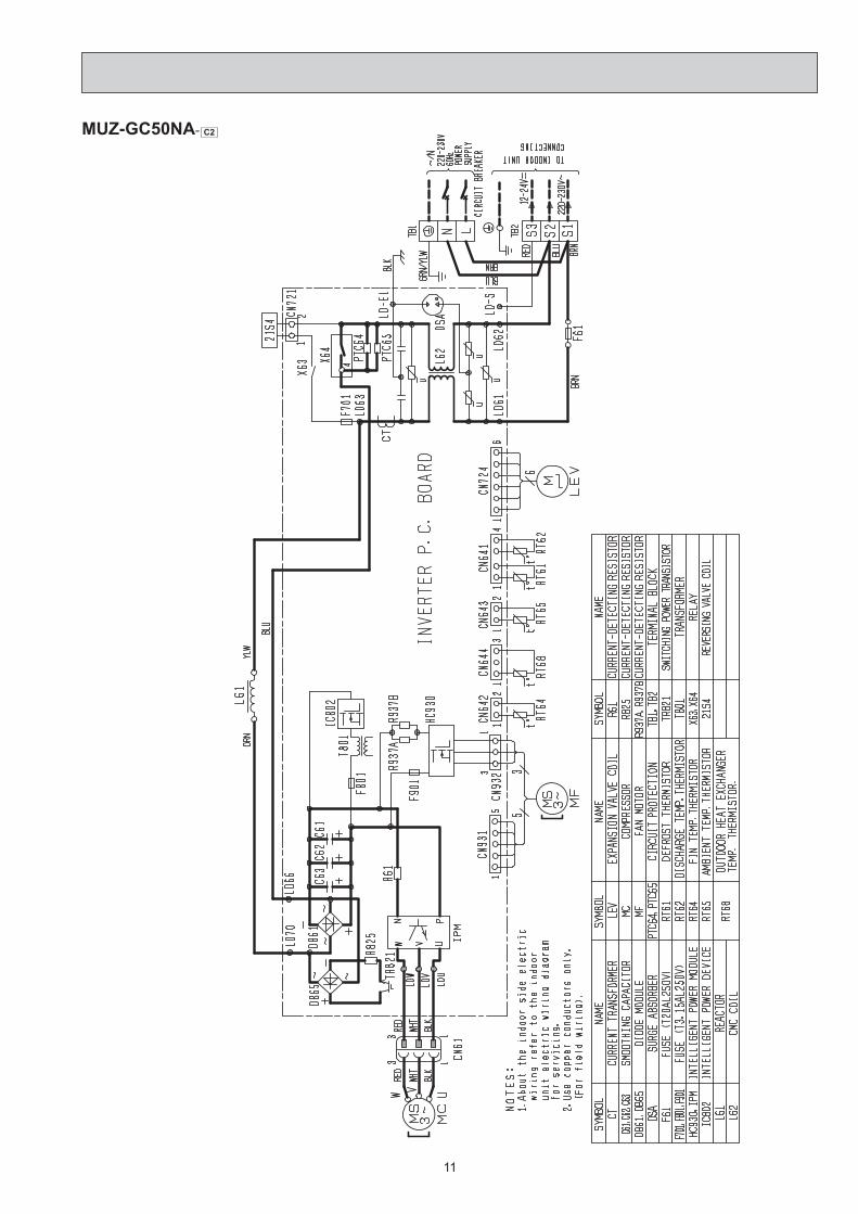
MUZ-GC50NA- C2

12
MUZ-GC60NA- C2

13
MUZ-GC71NA

14
OutdoorheatexchangerFlared connection
DefrostthermistorRT61
DischargetemperaturethermistorRT62
Flared connection
Stop valve(with strainer)
Stop valve(with service port)
Capillary tubeø3.0×ø2.0×260
Refrigerant flow in cooling
Compressor
4-way valve
Refrigerant flow in heating
Refrigerant pipe ø9.52(with heat insulator)
Refrigerant pipe ø6.35(with heat insulator)
LEVR.V. coilheating ONcooling OFF
Strainer#100
Muffler
Muffler
MUZ-GC25NA MUZ-GC35NA
MUZ-GC50NA- C1
Outdoorheatexchanger
Flared connection DefrostthermistorRT61
DischargetemperaturethermistorRT62
Flared connection
Stop valve
Stop valve(with service port)
Capillary tubeø3.6ø×2.4×50
Capillary tubeø1.8ø×0.6×1000
Refrigerant flow in cooling
Compressor
4-way valve
Refrigerant flow in heating
Refrigerant pipe ø12.7(with heat insulator)
Refrigerant pipe ø6.35(with heat insulator)
LEVR.V. coilheating ONcooling OFF
Oil separator
Strainer#100Receiver
OutdoorheatexchangertemperaturethermistorRT68
Strainer#100
Strainer#100 Ambient
temperaturethermistorRT65
Unit : mm
Unit : mm
5 REFRIGERANT SYSTEM DIAGRAM

15
MUZ-GC60NA- C1
Outdoorheatexchanger
Flared connection
DefrostthermistorRT61
DischargetemperaturethermistorRT62
Flared connection
Stop valve
Stop valve(with service port)
Capillary tubeø3.6ø×2.4×50
Refrigerant flow in cooling
Compressor
4-way valve
Refrigerant flow in heating
Refrigerant pipe ø15.88(with heat insulator)
Refrigerant pipe ø6.35(with heat insulator)
LEVR.V. coilheating ONcooling OFF
Muffler#100
Strainer#100Receiver
Outdoor heat exchangertemperaturethermistorRT68
AmbienttemperaturethermistorRT65
Strainer#100
MUZ-GC50NA - C2
Outdoorheatexchanger
Flared connection
DefrostthermistorRT61
DischargetemperaturethermistorRT62
Flared connection
Stop valve(with strainer)
Stop valve(with service port)
Capillary tube ø3.6ø×2.4×50
Refrigerant flow in cooling
Compressor
4-way valve
Refrigerant flow in heating
Refrigerant pipe ø12.7 (with heat insulator)
Refrigerant pipe ø6.35(with heat insulator)
LEV R.V. coil OFF ON
Muffler#100
Receiver
Outdoor heat exchangertemperaturethermistorRT68
AmbienttemperaturethermistorRT65
Strainer#100
Unit : mm
Unit : mm

16
MUZ-GC71NA
Outdoorheatexchanger
Flared connection DefrostthermistorRT61
DischargetemperaturethermistorRT62
Flared connection
Stop valve
Stop valve(with service port)
Capillary tubeø3.6ø×2.4×50
Capillary tubeø1.8ø×0.6×1000
Refrigerant flow in cooling
Compressor
4-way valve
Refrigerant flow in heating
Refrigerant pipe ø15.88(with heat insulator)
Refrigerant pipe ø9.52(with heat insulator)
LEVR.V. coilheating ONcooling OFF
Oil separator High-pressureswitch
Strainer#100Receiver
OutdoorheatexchangertemperaturethermistorRT68
Strainer#100
Strainer#100 Ambient
temperaturethermistorRT65
MUZ-GC60NA- C2 Unit : mm
Outdoorheatexchanger
Flared connection
DefrostthermistorRT61
DischargetemperaturethermistorRT62
Flared connection
Stop valve
Stop valve(with service port)
Capillary tubeø3.6ø×2.4×50
Refrigerant flow in cooling
Compressor
4-way valve
Refrigerant flow in heating
Refrigerant pipe ø15.88(with heat insulator)
Refrigerant pipe ø6.35(with heat insulator)
LEVR.V. coilheating ONcooling OFF
Muffler#100
Strainer#100Receiver
Outdoor heat exchangertemperaturethermistorRT68
AmbienttemperaturethermistorRT65
Strainer#100
High-pressureswitch
Unit : mm

17
Max. Length A
Max. Heightdifference
B
Indoorunit
Outdoor unit
MAX. REFRIGERANT PIPING LENGTH and MAX. HEIGHT DIFFERENCE
Model
Refrigerant piping : m Piping size O.D : mm
Max. Length A
Max. Height difference B Gas Liquid
MUZ-GC25NA MUZ-GC35NA 20 12 9.52
6.35MUZ-GC50NA 30 15
12.7MUZ-GC60NA 15.88MUZ-GC71NA 9.52
ADDITIONAL REFRIGERANT CHARGE (R410A : g)
Model Outdoor unit precharged
Refrigerant piping length (one way) 5 m 6 m 7 m 8 m 9 m 10 m 11 m 12 m 13 m 14 m 15 m 20 m
MUZ-GC25NA MUZ-GC35NA 750 0 0 0 90 120 150 180 210 240 270 300 450
Calculation : X g = 30 g/m × (Refrigerant piping length (m) – 5)
Model Outdoor unit precharged
Refrigerant piping length (one way) 7 m 10 m 15 m 20 m 25 m 30 m
MUZ-GC50NA 1,5000 60 160 260 360 460
MUZ-GC60NA 1,800Calculation : X g = 20 g/m × (Refrigerant piping length (m) – 7)
Model Outdoor unit precharged
Refrigerant piping length (one way) 7 m 10 m 15 m 20 m 25 m 30 m
MUZ-GC71NA 2,000 0 165 440 715 990 1,265
Calculation : X g = 55 g/m × (Refrigerant piping length (m) – 7)
NOTE : Refrigerant piping exceeding 7 m requires additional refrigerant charge according to the calculation.

18
MUZ-GC25NA MUZ-GC35NA MUZ-GC50NA MUZ-GC60NA MUZ-GC71NAThe standard specifications apply only to the operation of the air conditioner under normal conditions. Since operating condi-tions vary according to the areas where these units are installed, the following information has been provided to clarify the operating characteristics of the air conditioner under the conditions indicated by the performance curve.(1) GUARANTEED VOLTAGE 198 ~ 253V, 60Hz(2) AIR FLOW Air flow should be set at MAX.(3) MAIN READINGS (1) Indoor intake air wet-bulb temperature : °C [WB] (2) Indoor outlet air wet-bulb temperature : °C [WB] (3) Outdoor intake air dry-bulb temperature : °C [DB] (4) Total input: W (5) Indoor intake air dry-bulb temperature : °C [DB] (6) Outdoor intake air wet-bulb temperature : °C [WB] (7) Total input : W
Indoor air wet/dry-bulb temperature difference on the left side of the following chart shows the difference between the indoor intake air wet/dry-bulb temperature and the indoor outlet air wet/dry-bulb temperature for your reference at service.
}}
Cooling
Heating
How to measure the indoor air wet-bulb/dry-bulb temperature difference1. Attach at least 2 sets of wet and dry-bulb thermometers to the indoor air intake as shown in the figure, and at least 2 sets
of wet and dry-bulb thermometers to the indoor air outlet. The thermometers must be attached to the position where air speed is high.
2. Attach at least 2 sets of wet and dry-bulb thermometers to the outdoor air intake. Cover the thermometers to prevent direct rays of the sun.3. Check that the air filter is cleaned.4. Open windows and doors of room.5. Press the EMERGENCY OPERATION switch once (twice) to start the EMERGENCY COOL (HEAT) MODE.6. When system stabilizes after more than 15 minutes, measure temperature and take an average temperature.7. 10 minutes later, measure temperature again and check that the temperature does not change.
INDOOR UNIT OUTDOOR UNIT
Wet and dry-bulbthermometers
Wet and dry-bulbthermometers
8.7
8.0
7.3
6.6
5.9
5.3
MU
Z-G
C60
NA
Indo
or a
ir W
et-b
ulb
tem
pera
ture
diffe
renc
e (°
C)
MU
Z-G
C50
NA
8.7
8.0
7.3
6.6
5.9
5.3
MU
Z-G
C35
NA
9.0
8.3
7.5
6.8
6.1
5.4
MU
Z-G
C25
NA
7.5
6.8
6.3
5.7
5.1
4.5
MU
Z-G
C71
NA Outdoor intake air Dry-bulb temperature (°C) Outdoor intake air Dry-bulb temperature (°C)
10.7
9.8
8.9
8.0
7.2
6.4
Indoor intake air Wet-bulb temperature (°C) Indoor intake air Wet-bulb temperature (°C)
Cooling capacity (at Rated frequency) Total inpup (Cooling : at Rated frequency)6-1. CAPACITY AND INPUT CURVES
6 PERFORMANCE CURVES

19
20.919.317.716.114.512.911.39.7
22.420.719.017.215.513.812.110.3
Indo
or a
ir D
ry-b
ulb
tem
pera
ture
diffe
renc
e (°
C)
Indoor intake air D
ry-bulb temperature (°C)
Outdoor intake air Wet-bulb temperature (°C) Outdoor intake air Wet-bulb temperature (°C)
Indoor intake air Dry-bulb temperature (°C)M
UZ-
GC
35N
A
MU
Z-G
C25
NA
24.122.320.418.516.714.813.011.1
23.421.619.818.016.214.412.610.8
MU
Z-G
C60
NA
MU
Z-G
C50
NA
27.925.723.621.419.317.215.012.9
MU
Z-G
C71
NA
Heating capacity (at Rated frequency) Total inpup (Heating : at Rated frequency)
NOTE : The above broken lines are for the heating operation without any front and defrost operation.
6-2. CAPACITY AND INPUT CORRECTION BY OPERATIONAL FREQUENCY OF COMPRESSOR
The operational frequency of compressorThe operational frequency of compressor
Correction of Heating total input
The operational frequency of compressorThe operational frequency of compressor
MUZ-GC25NA
MUZ-GC35NA
Cap
acity
cor
rect
ion
fact
ors
Inpu
t cor
rect
ion
fact
ors
Inpu
t cor
rect
ion
fact
ors
Cap
acity
cor
rect
ion
fact
ors
Correction of Cooling capacity
The operational frequency of compressor
Correction of Cooling total input
The operational frequency of compressor
Correction of Heating total input
The operational frequency of compressor
Correction of Heating capacity
The operational frequency of compressor
MUZ-GC50NA
0 50 100 150(Hz)0.0
0.5
1.0
1.5
0 50 100 150(Hz)0.0
0.5
1.0
1.5
0 50 1000.0
0.5
1.0
1.5
0 50 100 150(Hz)0.0
0.5
1.0
1.5
0 50 100 150(Hz)0.0
0.5
1.0
1.5
2.0
Correction of Cooling capacity
Cap
acity
cor
rect
ion
fact
ors
The operational frequency of compressor
Correction of Cooling total input
Inpu
t cor
rect
ion
fact
ors
The operational frequency of compressor
Correction of Heating total input
Inpu
t cor
rect
ion
fact
ors
The operational frequency of compressor
Correction of Heating capacity
Cap
acity
cor
rect
ion
fact
ors
The operational frequency of compressor0 50 100 150(Hz)
0.0
0.5
1.0
1.5
0 50 100 150(Hz)0.0
0.5
1.0
1.5
0 50 100 150(Hz)0.0
0.5
1.0
1.5
2.0
0 50 100 150(Hz)0.0
0.5
1.0
1.5
2.0
Correction of Cooling total input
Inpu
t cor
rect
ion
fact
ors
Correction of Cooling capacity
Cap
acity
cor
rect
ion
fact
ors
Correction of Heating total inputCorrection of Heating capacityC
apac
ity c
orre
ctio
n fa
ctor
s
Inpu
t cor
rect
ion
fact
ors
0 50 100 150(Hz)0.0
0.5
1.0
1.5
0 50 100 150(Hz)0.0
0.5
1.0
1.5
0 50 100 150(Hz)0.0
0.5
1.0
1.5
2.0
0 50 100 150(Hz)0.0
0.5
1.0
1.5
2.0

20
MUZ-GC71NA
Cap
acity
cor
rect
ion
fact
ors
Inpu
t cor
rect
ion
fact
ors
Inpu
t cor
rect
ion
fact
ors
Cap
acity
cor
rect
ion
fact
ors
Correction of Cooling capacity
The operational frequency of compressor
Correction of Cooling total input
The operational frequency of compressor
Correction of Heating total input
The operational frequency of compressor
Correction of Heating capacity
The operational frequency of compressor0 50 100 150
0.5
1.0
1.5
(Hz) 0 50 100 150
0.5
1.0
1.5
(Hz) 0 50 100 150
0.5
1.0
1.5
(Hz) 0 50 100 150
0.5
1.0
1.5
(Hz)
Cap
acity
cor
rect
ion
fact
ors
Inpu
t cor
rect
ion
fact
ors
Inpu
t cor
rect
ion
fact
ors
Cap
acity
cor
rect
ion
fact
ors
Correction of Cooling capacity
The operational frequency of compressor
Correction of Cooling total input
The operational frequency of compressor
Correction of Heating total input
The operational frequency of compressor
Correction of Heating capacity
The operational frequency of compressor
MUZ-GC60NA
0 50 100 150
0.5
1.0
1.5
(Hz) 0 50 100 150
0.5
1.0
1.5
(Hz) 0 50 100 150
0.5
1.0
1.5
(Hz) 0 50 100 150
0.5
1.0
1.5
(Hz)
6-3. TEST RUN OPERATION (How to operate fixed-frequency operation)1. Press EMERGENCY OPERATION switch to COOL or HEAT mode (COOL : Press once, HEAT : Press twice).2. Test run operation starts and continues to operate for 30 minutes.3. Compressor operates at rated frequency in COOL mode or 58 Hz in HEAT mode.4. Indoor fan operates at High speed.5. After 30 minutes, test run operation finishes and EMERGENCY OPERATION starts (Operation frequency of compressor
varies).6. To cancel test run operation (EMERGENCY OPERATION), press EMERGENCY OPERATION switch or any button on
remote controller.

21
COOL operation Both indoor and outdoor unit are under the same tempera-ture/humidity condition.
Operation : TEST RUN OPERATION (refer to 6-3.)
6-4. OUTDOOR LOW PRESSURE AND OUTDOOR UNIT CURRENT(M
Pa [G
auge
])
(MPa
[Gau
ge])
(MPa
[Gau
ge])
18 3215 2050
2560
3070 (%)
35(°C)0.2
0.4
0.6
0.8
1.0
1.2
1.4
Ambient temperature(°C) Ambient humidity(%)
18 3215 2050
2560
3070 (%)
35(°C)
Ambient temperature(°C) Ambient humidity(%)
18 3215 2050
2560
3070 (%)
35(°C)
Ambient temperature(°C) Ambient humidity(%)
18 3215 2050
2560
3070 (%)
35(°C)
Ambient temperature(°C) Ambient humidity(%)
18 3215 2050
2560
3070 (%)
35(°C)
Ambient temperature(°C) Ambient humidity(%)
18 3215 2050
2560
3070 (%)
35(°C)
Ambient temperature(°C) Ambient humidity(%)
MUZ-GC25NA
18 3215 2050
2560
3070 (%)
35(°C)
Ambient temperature(°C) Ambient humidity(%)
2
2.5
3
3.5
4(A)
(MPa
[Gau
ge])
(MPa
[Gau
ge])
0.2
18 3215 2050
2560
3070 (%)
35(°C)
Ambient temperature(°C) Ambient humidity(%)
2
3
4
5
6
MUZ-GC35NA
MUZ-GC25NA MUZ-GC35NA MUZ-GC50NA
MUZ-GC71NA
MUZ-GC60NA(A)
MUZ-GC50NA
0.6
0.7
0.8
0.9
1.0
1.1
1.2MUZ-GC71NA
0.6
0.7
0.8
0.9
1.0
1.1
1.2
6
7
8
9
10
11
12
7
8
9
10
11
12
13
MUZ-GC60NA
(A)
(A)
Ambient temperature(°C) Ambient humidity(%)
18 3215 2050
2560
3070 (%)
35(°C)
Ambient temperature(°C) Ambient humidity(%)
18 3215 2050
2560
3070 (%)
35(°C)
4
5
6
7
8
0.5
0.6
0.7
0.8
0.9
1.0
(A)
2
4
6
8
10
kgf/
[G
auge
] 12
14
2
4
6
8
10
kgf/
[G
auge
] 12
14
5
6
7
8
kgf/
[G
auge
] 9
10
6
7
8
9
10
kgf/
[G
auge
] 11
12
6
7
8
9
10
kgf/
[G
auge
] 11
12
0.4
0.6
0.8
1.0
1.2
1.4
Outdoor low pressure
Outdoor unit current
NOTE : The unit of pressure has been changed to MPa on the international system of units (SI unit system). The conversion factor is : 1 (MPa [Gauge]) = 10.2 (kgf/cm2
[Gauge])
Dry-bulb temperature (°C) Relative humidity(%)20 5025 6030 70

22
Condition :
Indoor OutdoorDry bulb temperature (°C) 20.0 2 7 15 20.0Wet bulb temperature (°C) 14.5 1 6 12 14.5
Operation : TEST RUN OPERATION (refer to 6-3.)
HEAT operation
Ambient temperature(°C) Ambient temperature(°C)
MUZ-GC25NA MUZ-GC35NA (A) (A)
(A) (A)
3.0
2.5
2.0
1.5
1.0
0.5
0.02 5 10 15 20 25(°C)
4.0
3.5
3.0
2.5
2.0
1.5
1.02 5 10 15 20 25(°C)
Ambient temperature(°C)
MUZ-GC50NA6.5
6.0
5.5
5.0
4.5
4.0
3.5
Ambient temperature(°C)
MUZ-GC60NA
2 5 7 10 15 20 25(°C)
Ambient temperature(°C)
MUZ-GC71NA14.0
13.0
12.0
11.0
10.0
9.0
8.02 5 7 10 15 20 25(°C)
(A)
5 10 15 20 25(°C)4.0
5.0
6.0
7.0
8.0
2
Outdoor unit current
23
MUZ-GC25NA MUZ-GC35NA MUZ-GC50NA MUZ-GC60NA MUZ-GC71NA
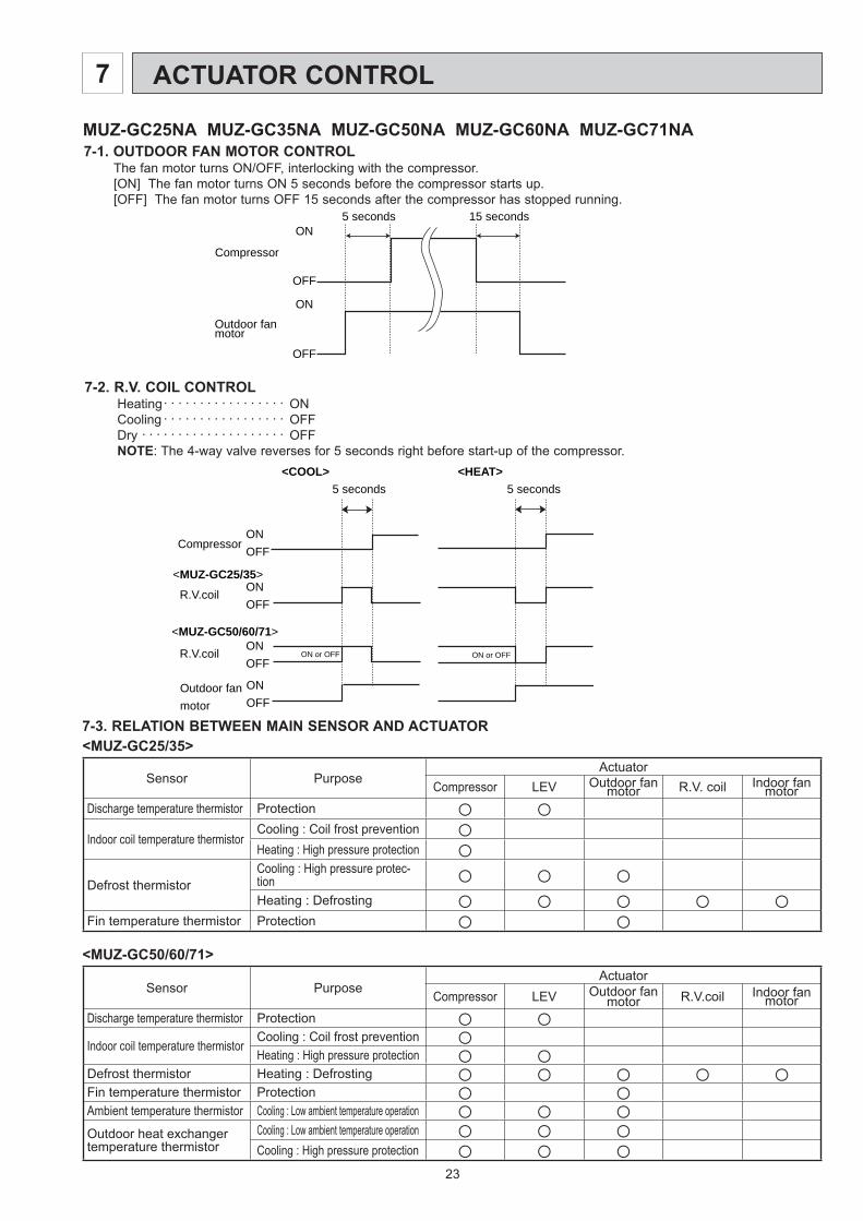
7-2. R.V. COIL CONTROLHeating . . . . . . . . . . . . . . . . . ONCooling . . . . . . . . . . . . . . . . . OFFDry . . . . . . . . . . . . . . . . . . . . OFFNOTE: The 4-way valve reverses for 5 seconds right before start-up of the compressor.
ON
OFF
ON
OFF
Outdoor fanmotor
Compressor
5 seconds 15 seconds
ONOFF
Compressor
Outdoor fanmotor
R.V.coil
<MUZ-GC25/35>ONOFF
ONOFF
<COOL>5 seconds
<HEAT>5 seconds
R.V.coil
<MUZ-GC50/60/71>ONOFF
ON or OFF ON or OFF
7-1. OUTDOOR FAN MOTOR CONTROLThe fan motor turns ON/OFF, interlocking with the compressor.[ON] The fan motor turns ON 5 seconds before the compressor starts up.[OFF] The fan motor turns OFF 15 seconds after the compressor has stopped running.
7-3. RELATION BETWEEN MAIN SENSOR AND ACTUATOR<MUZ-GC25/35>
Sensor PurposeActuator
Compressor LEV Outdoor fan motor R.V. coil Indoor fan
motorDischarge temperature thermistor Protection ○ ○Indoor coil temperature thermistor
Cooling : Coil frost prevention ○Heating : High pressure protection ○
Defrost thermistorCooling : High pressure protec-tion ○ ○ ○Heating : Defrosting ○ ○ ○ ○ ○
Fin temperature thermistor Protection ○ ○<MUZ-GC50/60/71>
Sensor PurposeActuator
Compressor LEV Outdoor fan motor R.V.coil Indoor fan
motorDischarge temperature thermistor Protection ○ ○Indoor coil temperature thermistor
Cooling : Coil frost prevention ○Heating : High pressure protection ○ ○
Defrost thermistor Heating : Defrosting ○ ○ ○ ○ ○Fin temperature thermistor Protection ○ ○Ambient temperature thermistor Cooling : Low ambient temperature operation ○ ○ ○Outdoor heat exchanger temperature thermistor
Cooling : Low ambient temperature operation ○ ○ ○Cooling : High pressure protection ○ ○ ○
ACTUATOR CONTROL7

24
8-1. CHANGE IN DEFROST SETTING [MUZ-GC25/35 MUZ-GC50NA- C2 ]Changing defrosting finish temperature<JS> When the JS wire of the outdoor Inverter P.C. board is cut/soldered, the defrost finish temperature is changed. (Refer to 9-6.1.)
Jumper wire Defrost fi nish temperature (°C)MUZ-GC25/35 MUZ-GC50NA- C2
JS
Soldered(Initial setting) 5 9
None(Cut) 8 18
8-2. PRE-HEAT CONTROL SETTING [MUZ-GC25/35 MUZ-GC50NA- C2 ]PRE-HEAT CONTROLWhen moisture gets into the refrigerant cycle, it may interfere the start-up of the compressor at low outside tempera-ture. The pre-heat control prevents this interference. The pre-heat control turns ON when outside temperature is 20°C or below. When pre-heat control is turned ON, compressor is energized. (About 50 W)
<JK> When the JK wire of the inverter P.C. board is cut, pre-heat control is activated. (Refer to 9-6.1)
NOTE: When the inverter P.C. board is replaced, check the Jumper wires, and cut/solder them if necessary.
9 TROUBLESHOOTING
3. Troubleshooting procedure1) First, check if the OPERATION INDICATOR lamp on the indoor unit is flashing on and off to indicate an abnormality.
To make sure, check how many times the abnormality indication is flashing on and off before starting service work.2) Before servicing check that the connector and terminal are connected properly.3) If the electronic control P.C. board is supposed to be defective, check the copper foil pattern for disconnection and
the components for bursting and discoloration.4) Refer to 9-2. and 9-3.
9-1. CAUTIONS ON TROUBLESHOOTING 1. Before troubleshooting, check the following
1) Check the power supply voltage.2) Check the indoor/outdoor connecting wire for miswiring.
2. Take care of the following during servicing1) Before servicing the air conditioner, be sure to turn OFF the main unit first with the remote controller, and then after
confirming the horizontal vane is closed, turn OFF the breaker and/or disconnect the power plug.2) Be sure to turn OFF the power supply before removing the front panel, the cabinet, the top panel, and the electronic
control P.C. board.3) When removing the electrical parts, be careful to the residual voltage of smoothing capacitor. 4) When removing the electronic control P.C. board, hold the edge of the board with care NOT to apply stress on the
components.5) When connecting or disconnecting the connectors, hold the housing of the connector. DO NOT pull the lead wires.
MUZ-GC25NA MUZ-GC35NA MUZ-GC50NA MUZ-GC60NA MUZ-GC71NA
Lead wiring Housing point
8 SERVICE FUNCTIONS

25
Outline of the functionThis air conditioner can memorize the abnormal condition which has occurred once.Even though LED indication listed on the troubleshooting check table (9-3.) disappears, the memorized failure details can be recalled.This mode is very useful when the unit needs to be repaired for the abnormality which doesn't recur.
9-2. FAILURE MODE RECALL FUNCTION
1. Flow chart of failure mode recall function for the indoor/outdoor unit
Does the upper or left lamp of OPERATION INDICATOR lamp on the indoor unit blink at the interval of 0.5 seconds?Blinks: Either indoor or outdoor unit is abnormal. Beep is emit-
ted at the same timing as the blinking of the upper or left lamp of OPERATION INDICATOR lamp. 2
Indoor unit is normal.But the outdoor unit might be abnormal because there are some abnor-malities that can't be recalled with this way.Confi rm if outdoor unit is abnormal according to the detailed outdoor unit failure mode recall function. (Refer to 9-2.2)
No
Yes
The cause of abnormality cannot be found because the abnormality doesn't recur.
Setting up the failure mode recall function
Turn ON the power supply.<Preparation of the remote controller>
While pressing both OPERATION SELECT button and TOO COOL button on the remote controller at the same time, press RESET button. First, release RESET button.
And release the other two buttons after all LCD in operation display section of the remote controller is displayed after 3 seconds.
Press OPERATE/STOP (ON/OFF) button of the remote controller (the set temperature is displayed) with the remote controller headed towards the indoor unit. 1
Judgment of indoor/outdoor abnormalityBefore blinking, does the upper or left lamp of OPERATION INDICATOR lamp stay ON for 3 seconds?Stays ON for 3 seconds (without beep): The outdoor unit is abnormal.
The indoor unit is abnormal.Check the blinking pattern, and confi rm the abnormal point with the indoor unit failure mode table. (Refer to indoor unit service manual.)Make sure to check at least two consecutive blinking cycles. 2
Releasing the failure mode recall functionRelease the failure mode recall function by the following procedures.Turn OFF the power supply and turn it ON again.Press RESET button of the remote controller.
The outdoor unit is abnormal.Check the blinking pattern, and confi rm the abnormal point with the outdoor unit failure mode table. (Refer to 9-2.3)Make sure to check at least two consecutive blinking cycles. 3
Repair the defective parts.
Deleting the memorized abnormal condition After repairing the unit, recall the failure mode again according to "Setting up the failure mode recall function" mentioned above. Press OPERATE/STOP (ON/OFF) button of the remote controller (the set temperature is displayed) with the remote controller headed towards the indoor unit. Press EMERGENCY OPERATION switch so that the memorized abnormal condition is deleted. Release the failure mode recall function according to "Releasing the failure mode recall function" mentioned above.
Operational procedure
Yes (Blinks)
No (OFF)
NOTE: 1. Make sure to release the failure mode recall function once it's set up, otherwise the unit cannot operate properly. 2. If the abnormal condition is not deleted from the memory, the last abnormal condition is kept memorized.
1. Regardless of normal or abnormal condition, a short beep is emitted once the signal is received.
2. Blinking pattern when the indoor unit is abnormal:
3.Blinking pattern when the outdoor unit is abnormal:
ONOFF
BeepsRepeated cycle Repeated cycle
ONOFF
No beep BeepsRepeated cycle
2.5-second OFFBlinking at 0.5-second interval
2.5-second OFF 3-second ONBlinking at 0.5-second interval
BeepsRepeated cycle
2.5-second OFFBlinking at 0.5-second interval
No beep BeepsRepeated cycle
2.5-second OFF 3-second ONBlinking at 0.5-second interval
Repeated cycle
Beeps
<MUZ-GC25/35/50> <MUZ-GC60/71>
26
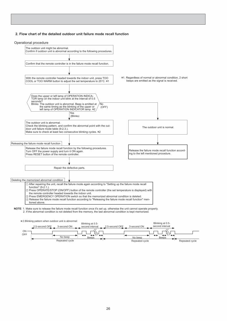
2. Flow chart of the detailed outdoor unit failure mode recall function
2.Blinking pattern when outdoor unit is abnormal:
ONOFF
No beep BeepsRepeated cycle
2.5-second OFF 3-second ONBlinking at 0.5-second interval
No beep BeepsRepeated cycle
2.5-second OFF 3-second ONBlinking at 0.5-second interval
Repeated cycle
Does the upper or left lamp of OPERATION INDICA-TOR lamp on the indoor unit blink at the interval of 0.5 seconds?Blinks: The outdoor unit is abnormal. Beep is emitted at
the same timing as the blinking of the upper or left lamp of OPERATION INDICATOR lamp. 2
Yes (Blinks)
No (OFF)
The outdoor unit might be abnormal.Confi rm if outdoor unit is abnormal according to the following procedures.
Operational procedure
Confi rm that the remote controller is in the failure mode recall function.
With the remote controller headed towards the indoor unit, press TOO COOL or TOO WARM button to adjust the set temperature to 25°C. 1
1. Regardless of normal or abnormal condition, 2 short beeps are emitted as the signal is received.
The outdoor unit is abnormal.Check the blinking pattern, and confi rm the abnormal point with the out-door unit failure mode table (9-2.3.).Make sure to check at least two consecutive blinking cycles. 2
Releasing the failure mode recall function
Release the failure mode recall function by the following procedures.Turn OFF the power supply and turn it ON again.Press RESET button of the remote controller.
Repair the defective parts.
The outdoor unit is normal.
Release the failure mode recall function accord-ing to the left mentioned procedure.
Deleting the memorized abnormal condition After repairing the unit, recall the failure mode again according to "Setting up the failure mode recall function" (9-2.1.). Press OPERATE/STOP (ON/OFF) button of the remote controller (the set temperature is displayed) with the remote controller headed towards the indoor unit. Press EMERGENCY OPERATION switch so that the memorized abnormal condition is deleted. Release the failure mode recall function according to "Releasing the failure mode recall function" men-tioned above.
NOTE: 1. Make sure to release the failure mode recall function once it's set up, otherwise the unit cannot operate properly. 2. If the abnormal condition is not deleted from the memory, the last abnormal condition is kept memorized.

27
3. Outdoor unit failure mode table MUZ-GC25/35NA
The upper lamp of OPERATION
INDICATOR lamp (Indoor unit)
Abnormal point (Failure mode / protection)
LED indication (Outdoor P.C.
board)Condition Correspondence
Indoor/outdoor unit failure mode recall
function
Outdoor unit failure mode
recall function
OFF None (Normal) — — — — —2-time fl ash 2.5 seconds OFF
Outdoor power system
—
Overcurrent protection stop is continuously performed 3 times within 1 minute after the compressor gets started.
•Reconnect connectors.•Refer to 9-5. "How to check inverter/compressor"
•Check stop valve. ○ ○
3-time fl ash 2.5 seconds OFF
Discharge temperature thermistor
1-time fl ash every 2.5 seconds
Thermistor shorts or opens during compressor running.
•Refer to 9-5. "Check of outdoor thermistors". Defective outdoor thermistors can be identifi ed by checking the blinking pattern of LED.
○ ○Defrost thermistor Fin temperature thermistor 3-time fl ash
2.5 seconds OFF P.C. board temperature thermistor
4-time fl ash 2.5 seconds OFF
4-time fl ash 2.5 seconds OFF
Overcurrent 11-time fl ash 2.5 seconds OFF
Large current fl ows into intelligent power module.
•Reconnect compressor connector
•Refer to 9-5. "How to check inverter/compressor"
•Check stop valve.
— ○Compressor synchronous abnormality (Compressor start-up failure protection)
12-time fl ash 2.5 seconds OFF
Waveform of compressor current is distorted.
•Reconnect compressor connector.
•Refer to 9-5. "How to check inverter/compressor".
— ○5-time fl ash 2.5 seconds OFF
Discharge temperature
—
Temperature of discharge temperature thermistor exceeds 116°C, compressor stops. Compressor can restart if discharge temperature thermistor reads 100°C or less 3 minutes later.
•Check refrigerant circuit and refrigerant amount.
•Refer to 9-5. "Check of LEV".
— ○6-time fl ash 2.5 seconds OFF
High pressure —
Temperature indoor coil thermistor exceeds 70°C in HEAT mode. Temperature defrost thermistor exceeds 70°C in COOL mode.
•Check refrigerant circuit and refrigerant amount.
•Check stop valve. — ○7-time fl ash 2.5 seconds OFF
Fin temperature / P.C. board temperature
7-time fl ash 2.5 seconds OFF
Temperature of fi n temperature thermistor on the inverter P.C. board exceeds 82 - 83°C, or temperature of P.C. board temperature thermistor on the inverter P.C. board exceeds 81 - 85°C.
•Check around outdoor unit.
•Check outdoor unit air passage.
•Refer to 9-5. "Check of outdoor fan motor".
— ○9-time fl ash 2.5 seconds OFF
Nonvolatile memory data — Nonvolatile memory data cannot be read properly.
•Replace the inverter P.C. board. ○ ○
10-time fl ash 2.5 seconds OFF
Discharge temperature 5-time fl ash 2.5 seconds OFF
Temperature of discharge temperature thermistor has been 50°C or less for 20 minutes.
•Refer to 9-5. "Check of LEV".
•Check refrigerant circuit and refrigerant amount.
— ○11-time fl ash 2.5 seconds OFF
DC voltage — DC voltage of inverter cannot be detected normally.
•Refer to 9-5. "How to check inverter/compressor". — ○Each phase current of
compressor 8-time fl ash 2.5 seconds OFF
Each phase current of compressor cannot be detected normally.
12-time fl ash 2.5 seconds OFF
Overcurrent Compressor open-phase
9-time fl ash 2.5 seconds OFF 10-time fl ash 2.5 seconds OFF
Large current fl ows into intelligent power module (IPM). The open-phase operation of compressor is detected. The interphase short out occurs in the output of the intelligent power module (IPM). The compressor winding shorts out.
•Reconnect compressor connector.
•Refer to 9-5. "How to check inverter/compressor".
— ○14-time fl ash 2.5 seconds OFF
Stop valve (Closed valve) 14-time fl ash 2.5 seconds OFF
Closed valve is detected by compressor current.
•Check stop valve ○ ○NOTE: Blinking patterns of this mode differ from the ones of Troubleshooting check table (9-3.).
28
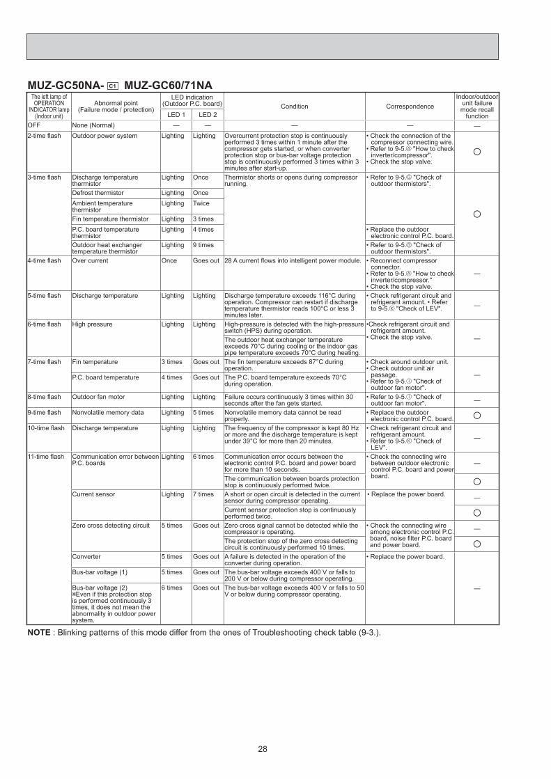
MUZ-GC50NA- C1 MUZ-GC60/71NAThe left lamp of OPERATION
INDICATOR lamp (Indoor unit)
Abnormal point(Failure mode / protection)
LED indication (Outdoor P.C. board) Condition Correspondence
Indoor/outdoor unit failure mode recall
functionLED 1 LED 2 OFF None (Normal) — — — — —2-time fl ash Outdoor power system Lighting Lighting Overcurrent protection stop is continuously
performed 3 times within 1 minute after the compressor gets started, or when converter protection stop or bus-bar voltage protection stop is continuously performed 3 times within 3 minutes after start-up.
• Check the connection of the compressor connecting wire.
• Refer to 9-5. "How to check inverter/compressor".
• Check the stop valve. ○
3-time fl ash Discharge temperature thermistor
Lighting Once Thermistor shorts or opens during compressor running.
• Refer to 9-5. "Check of outdoor thermistors".
○Defrost thermistor Lighting Once Ambient temperature thermistor
Lighting Twice
Fin temperature thermistor Lighting 3 times P.C. board temperature thermistor
Lighting 4 times • Replace the outdoor electronic control P.C. board.
Outdoor heat exchanger temperature thermistor
Lighting 9 times • Refer to 9-5. "Check of outdoor thermistors".
4-time fl ash Over current Once Goes out 28 A current fl ows into intelligent power module. • Reconnect compressor connector.
• Refer to 9-5. "How to check inverter/compressor."
• Check the stop valve.
—
5-time fl ash Discharge temperature Lighting Lighting Discharge temperature exceeds 116°C during operation. Compressor can restart if discharge temperature thermistor reads 100°C or less 3 minutes later.
• Check refrigerant circuit and refrigerant amount. • Refer to 9-5. "Check of LEV". —
6-time fl ash High pressure Lighting Lighting High-pressure is detected with the high-pressure switch (HPS) during operation.
•Check refrigerant circuit and refrigerant amount.
• Check the stop valve. —The outdoor heat exchanger temperature exceeds 70°C during cooling or the indoor gas pipe temperature exceeds 70°C during heating.
7-time fl ash Fin temperature 3 times Goes out The fi n temperature exceeds 87°C during operation.
• Check around outdoor unit.• Check outdoor unit air
passage.• Refer to 9-5. "Check of
outdoor fan motor".
—P.C. board temperature 4 times Goes out The P.C. board temperature exceeds 70°C during operation.
8-time fl ash Outdoor fan motor Lighting Lighting Failure occurs continuously 3 times within 30 seconds after the fan gets started.
• Refer to 9-5. "Check of outdoor fan motor". —
9-time fl ash Nonvolatile memory data Lighting 5 times Nonvolatile memory data cannot be read properly.
• Replace the outdoor electronic control P.C. board. ○
10-time fl ash Discharge temperature Lighting Lighting The frequency of the compressor is kept 80 Hz or more and the discharge temperature is kept under 39°C for more than 20 minutes.
• Check refrigerant circuit and refrigerant amount.
• Refer to 9-5. "Check of LEV".
—
11-time fl ash Communication error between P.C. boards
Lighting 6 times Communication error occurs between the electronic control P.C. board and power board for more than 10 seconds.
• Check the connecting wire between outdoor electronic control P.C. board and power board.
—
The communication between boards protection stop is continuously performed twice. ○
Current sensor Lighting 7 times A short or open circuit is detected in the current sensor during compressor operating.
• Replace the power board. —
Current sensor protection stop is continuously performed twice. ○
Zero cross detecting circuit 5 times Goes out Zero cross signal cannot be detected while the compressor is operating.
• Check the connecting wire among electronic control P.C. board, noise fi lter P.C. board and power board.
—
The protection stop of the zero cross detecting circuit is continuously performed 10 times. ○
Converter 5 times Goes out A failure is detected in the operation of the converter during operation.
• Replace the power board.
—
Bus-bar voltage (1) 5 times Goes out The bus-bar voltage exceeds 400 V or falls to 200 V or below during compressor operating.
Bus-bar voltage (2) Even if this protection stop
is performed continuously 3 times, it does not mean the abnormality in outdoor power system.
6 times Goes out The bus-bar voltage exceeds 400 V or falls to 50 V or below during compressor operating.
NOTE : Blinking patterns of this mode differ from the ones of Troubleshooting check table (9-3.).

29
MUZ-GC50NA- C2
The left lamp of OPERATION INDICATOR lamp (Indoor unit)
Abnormal point(Failure mode / protection)
LED indication(Outdoor P.C. board) Condition Correspondence
Indoor/outdoor unit failure mode recall
function
Outdoor unit failure mode
recall function
OFF None (Normal) — — — — —
2-time fl ash 2.5 seconds OFF
Outdoor power system
—
Overcurrent protection stop is continuously performed 3 times within 1 minute after the compressor gets started.
Reconnect connectors.Refer to 9-5. "How to check inverter/compressor".Check stop valve.
••
•○ ○
3-time fl ash2.5 seconds OFF
Discharge temperature thermistor
1-time fl ash every 2.5 seconds
Thermistor shorts or opens during compressor running.
Refer to 9-5."Check of outdoor thermistors". Defective outdoor thermistors can be identifi ed by checking the blinking pattern of LED.
•
•
○ ○Defrost thermistor
Fin temperature thermistor 3-time fl ash2.5 seconds OFF
P.C. board temperature thermistor
4-time fl ash2.5 seconds OFF
Ambient temperature thermistor
2-time fl ash 2.5 seconds OFF
4-time fl ash 2.5 seconds OFF
Overcurrent 11-time fl ash 2.5 seconds OFF
Large current fl ows into intelligent power module.
Reconnect compressor connector.Refer to 9-5. "How to check inverter/compressor".Check stop valve.
•
•
•
— ○Compressor synchronous abnormality (Compressor start-up failure protection)
12-time fl ash 2.5 seconds OFF
Waveform of compressor current is distorted.
Reconnect compressor connector.Refer to 9-5. "How to check inverter/compressor".
•
• — ○5-time fl ash 2.5 seconds OFF
Discharge temperature
—
Temperature of discharge temperature thermistor exceeds 116°C, compressor stops.Compressor can restart if discharge temperature thermistor reads 100°C or less 3 minutes later.
Check refrigerant circuit and refrigerant amount.Refer to 9-5. "Check of LEV".
•
• — ○
6-time fl ash 2.5 seconds OFF
High pressure
—
Temperature indoor coil thermistor exceeds 70°C in HEAT mode. Temperature defrost thermistor exceeds 70°C in COOL mode.
Check refrigerant circuit and refrigerant amount.Check stop valve.
•
•— ○
7-time fl ash 2.5 seconds OFF
Fin temperature/ P.C. board temperature
7-time fl ash 2.5 seconds OFF
Temperature of fi n temperature thermistor on the inverter P.C. board exceeds 75 ~ 80°C, or temperature of P.C. board temperature thermistor on the inverter P.C. board exceeds 70 ~ 75°C.
Check around outdoor unit.Check outdoor unit air passage.Refer to 9-5. "Check of outdoor fan motor".
•
•
•— ○
8-time fl ash 2.5 seconds OFF
Outdoor fan motor—
Outdoor fan has stopped 3 times in a row within 30 seconds after outdoor fan start-up.
Refer to 9-5. "Check of outdoor fan motor". Refer to 9-5. "Check of inverter P.C. board".
•— ○
9-time fl ash 2.5 seconds OFF
Nonvolatile memory data 5-time fl ash 2.5 seconds OFF
Nonvolatile memory data cannot be read properly.
Replace the inverter P.C. board.
• ○ ○10-time fl ash 2.5 seconds OFF
Discharge temperature
—
Temperature of discharge temperature thermistor has been 50°C or less for 20 minutes.
Refer to 9-5. "Check of LEV".Check refrigerant circuit and refrigerant amount.
•
• — ○11-time fl ash 2.5 seconds OFF
DC voltage 8-time fl ash 2.5 seconds OFF
DC voltage of inverter cannot be detected normally.
Refer to 9-5. "How to check inverter/compressor".
•
— ○Each phase current of compressor
9-time fl ash 2.5 seconds OFF
Each phase current of compressor cannot be detected normally.
12-time fl ash 2.5 seconds OFF
Overcurrent Compressor open-phase
10-time fl ash 2.5 seconds OFF
Large current fl ows into intelligent power module (IPM).The open-phase operation of compressor is detected.The interphase short out occurs in the output of the intelligent power module (IPM).The compressor winding shorts out.
Reconnect compressor connector.Refer to 9-5. "How to check inverter/compressor".
•
•
— ○
14-time fl ash 2.5 seconds OFF
Stop valve (Closed valve) 14-time fl ash 2.5 seconds OFF
Closed valve is detected by compressor current.
Check stop valve• ○ ○NOTE: Blinking patterns of this mode differ from the ones of Troubleshooting check table (9-3.).

30
9-3. TROUBLESHOOTING CHECK TABLEMUZ-GC25/35NANo. Symptom LED indication Abnormal point/
Condition Condition Correspondence
1
Outdoor unit does not operate.
1-time fl ash every 2.5 seconds
Outdoor power system Overcurrent protection stop is continuously performed 3 times within 1 minute after the compressor gets started.
• Reconnect connector of compressor.
• Refer to 9-5. "How to check inverter/compressor".
• Check stop valve.
2Outdoor thermistors Discharge temperature thermistor, fi n temperature thermistor,
defrost thermistor or P.C. board temperature thermistor shorts or opens during compressor running.
• Refer to 9-5. "Check of outdoor thermistors".
3Outdoor control system Nonvolatile memory data cannot be read properly. (When the
upper lamp of OPERATION INDICATOR lamp of the indoor unit lights up or fl ashes 7-time.)
Replace inverter P.C. board.
4 6-time fl ash 2.5 seconds OFF
Serial signal The communication fails between the indoor and outdoor unit for 3 minutes.
Refer to 9-5. "How to check miswiring and serial signal error.
5 11-time fl ash 2.5 seconds OFF
Stop valve / Closed valve
Closed valve is detected by compressor current. • Check stop valve.
614-time fl ash 2.5 seconds OFF
Outdoor unit (Other abnormality)
Outdoor unit is defective. Refer to 9-2.2. "Flow chart of the detailed outdoor unit failure mode recall function".
7
'Outdoor unit stops and restarts 3 minutes later' is repeated.
2-time fl ash 2.5 seconds OFF
Overcurrent protection Large current fl ows into intelligent power module. • Reconnect connector of compressor.
• Refer to 9-5. "How to check inverter/compressor".
• Check stop valve.
83-time fl ash 2.5 seconds OFF
Discharge temperature overheat protection
Temperature of discharge temperature thermistor exceeds 116°C, compressor stops. Compressor can restart if discharge temperature thermistor reads 100°C or less 3 minutes later.
• Check refrigerant circuit and refrigerant amount.
• Refer to 9-5. "Check of LEV".
94-time fl ash 2.5 seconds OFF
Fin temperature /P.C. board temperature thermistor overheat protection
Temperature of fi n temperature thermistor on the heat sink exceeds 82 - 83°C or temperature of P.C. board temperature thermistor on the inverter P.C.board exceeds 81 - 85°C.
• Check around outdoor unit. • Check outdoor unit air passage. • Refer to 9-5. "Check of outdoor
fan motor".
105-time fl ash 2.5 seconds OFF
High pressure protection
Indoor coil thermistor exceeds 70°C in HEAT mode. Defrost thermistor exceeds 70°C in COOL mode.
• Check refrigerant circuit and refrigerant amount.
• Check stop valve.
118-time fl ash 2.5 seconds OFF
Compressor synchronous abnormality
The waveform of compressor current is distorted. • Reconnect connector of compressor.
• Refer to 9-5. "How to check inverter/compressor".
12 12-time fl ash 2.5 seconds OFF
Each phase current of compressor
Each phase current of compressor cannot be detected normally • Refer to 9-5. "How to check inverter/compressor".
13 13-time fl ash 2.5 seconds OFF
DC voltage DC voltage of inverter cannot be detected normally. • Refer to 9-5. "How to check inverter/compressor".
14 Outdoor unit operates.
1-time fl ash 2.5 seconds OFF
Frequency drop by current protection
Current from power outlet reaches the protection current, and compressor frequency lowers.
The unit is normal, but check the following. • Check if indoor fi lters are clogged.• Check if refrigerant is short. • Check if indoor/outdoor unit air
circulation is short cycled. 15
3-time fl ash 2.5 seconds OFF
Frequency drop by high pressure protection
Temperature of indoor coil thermistor exceeds 55°C in HEAT mode, compressor frequency lowers.
Frequency drop by defrosting in COOL
mode
Indoor coil thermistor reads 8°C or less in COOL mode, compressor frequency lowers.
16
4-time fl ash 2.5 seconds OFF
Frequency drop by discharge temperature protection
Temperature of discharge temperature thermistor exceeds 111°C, compressor frequency lowers.
• Check refrigerant circuit and refrigerant amount.
• Refer to 9-5. "Check of LEV". • Refer to 9-5. "Check of outdoor
thermistors".
17Outdoor unit operates.
7-time fl ash 2.5 seconds OFF
Low discharge temperature protection
Temperature of discharge temperature thermistor has been 50°C or less for 20 minutes.
• Refer to 9-5. "Check of LEV". • Check refrigerant circuit and
refrigerant amount.
18
8-time fl ash 2.5 seconds OFF
PAM protection PAM: Pulse Amplitude Modulation
The overcurrent fl ows into IGBT (Insulated Gate Bipolar transistor : TR821) or when the bus-bar voltage reaches 320 V or more, PAM stops and restarts.
This is not malfunction. PAM protection will be activated in the following cases;
Instantaneous power voltage drop. (Short time power failure)
When the power supply voltage is high.
199-time fl ash 2.5 seconds OFF
Inverter check mode The connector of compressor is disconnected, inverter check mode starts.
Check if the connector of the compressor is correctly connected. Refer to 9-5. "How to check inverter/compressor".
NOTE: 1. The location of LED is illustrated at the right fi gure. Refer to 9-6.1. 2. LED is lighted during normal operation.
The fl ashing frequency shows the number of times the LED blinks after every 2.5-second OFF.(Example) When the fl ashing frequency is "2".
Inverter P.C. board (Parts side)
LEDFlashing
ON
OFF2.5-second OFF 2.5-second OFF
0.5-second ON 0.5-second ON

31
MUZ-GC50NA- C1 MUZ-GC60/71NANo. Symptom
Indication Abnormal point /
Condition Condition CorrespondenceLED1 (Red)
LED2 (Yellow)
1
Outdoor unit does not op-erate.
Lightning Twice
Outdoor power system
Overcurrent protection stop is continuously performed 3 times within 1 minute after the compressor gets started, or when converter protection stop or bus-bar voltage protection stop is continuously performed 3 times within 3 minutes after start-up.
• Check the connection of the com-pressor connecting wire.
• Refer to 9-5. "How to check in-verter/compressor".
• Check the stop valve.
2Lightning 3 times Discharge temperature
thermistor A short circuit is detected in the thermistor during operation, or when an open circuit is detected in the thermistor after 10 min-utes of compressor start-up.
• Refer to 9-5. "Check of outdoor thermistor".
3
Lightning 4 times Fin temperature ther-mistor A short or open circuit is detected in the thermistor during op-
eration.
• Refer to 9-5. "Check of outdoor thermistor".
P.C board temperature thermistor
• Replace the outdoor electronic control P.C. board.
4
Lightning 5 times Ambient temperature thermistor
A short or open circuit is detected in the thermistor during op-eration.
• Refer to 9-5. "Check of outdoor thermistor".
Outdoor heat exchanger temperature thermistor
A short circuit is detected in the thermistor during operation, or an open circuit is detected in the thermistor after 5 minutes (in cooling) and 10 minutes (in heating) of compressor start-up.
Defrost thermistor A short circuit is detected in the thermistor during operation, or an open circuit is detected in the thermistor after 5 minutes of compressor start-up.
5 Lightning 6 times Serial signal The communication fails between the indoor and outdoor unit for 3 minutes.
• Refer to 9-5. "How to check mis-wiring and serial signal error.
6 Lightning 7 times Nonvolatile memory data The nonvolatile memory data cannot be read properly. • Replace the outdoor electronic
control P.C. board. 7 Lightning 8 times Current sensor Current sensor protection stop is continuously performed twice. • Replace the power board.
8Lightning 11 times Communication error
between P.C. boards The communication protection stop between boards is continu-ously performed twice.
• Check the connecting wire be-tween outdoor electronic control P.C. board and power board.
9Lightning 12 times
Zero cross detecting circuit
The protection stop of the zero cross detecting circuit is con-tinuously performed 10 times.
• Check the connecting wire among outdoor electronic control P.C. board, noise fi lter P.C. board and power board.
10
Outdoor unit stops and restarts 3 minutes later' is repeated.
Twice Goes out
IPM protection Over-current is detected after 30 minutes of compressor start-up.
• Reconnect compressor connector. • Refer to 9-5. "How to check in-
verter/compressor". • Check the stop valve. • Check the power module (PAM
module). Lock protection Over-current is detected within 30 minutes of compressor start-up.
113 times Goes out Discharge temperature
protection Discharge temperature exceeds 116°C during operation and compressor stops. Compressor can restart if discharge tem-perature thermistor reads 100°C or less 3 minutes later.
• Check the amount of gas and re-frigerant circuit.
• Refer to 9-5. "Check of LEV".
12
4 times Goes out Fin temperature protec-tion The fi n temperature exceeds 87°C during operation. • Check around outdoor unit.
• Check outdoor unit air passage.• Refer to 9-5. "Check of outdoor
fan motor".P.C. board temperature protection The P.C. board temperature exceeds 70°C during operation.
5 times Goes out High-pressure protec-tion
High-pressure is detected with the high-pressure switch (HPS) during operation.
• Check around of gas and the re-frigerant circuit.
• Check of stop valve. 13
The outdoor heat exchanger temperature exceeds 70°C during cooling or indoor gas pipe temperature exceeds 70°C during heating.
14 8 times Goes out Converter protection A failure is detected in the operation of the converter during op-eration. • Replace the power board.
15
9 times Goes out Bus-bar voltage protec-tion (1)
The bus-bar voltage exceeds 400 V or falls to 200 V or below during compressor operating.
• Replace the power board. Bus-bar voltage protec-tion (2)
The bus-bar voltage exceeds 400 V or falls to 50 V or below during compressor operating.
16 13 times Goes out Outdoor fan motor Failure occurs continuously 3 times within 30 seconds after the fan gets started.
• Refer to 9-5. "Check of outdoor fan motor".
17 Lighting 8 times Current sensor protec-tion
A short or open circuit is detected in the current sensor during compressor operating. • Replace the power board.
18Lighting 11 times Communication be-
tween P.C. boards pro-tection
Communication error occurs between the outdoor electronic control P.C. board and power board for more than 10 seconds.
• Check the connecting wire be-tween outdoor electronic control P.C. board and power board.
19Lighting 12 times Zero cross detecting
circuit protection Zero cross signal cannot be detected while the compressor is operating.
• Check the connecting wire among outdoor electronic control P.C. board, noise fi lter P.C. board and power board.
NOTE: 1. The location of LED is illustrated at the right fi gure. Refer to 9-6.2. 2. LED is lighted during normal operation.
The fl ashing frequency shows the number of times the LED blinks after every 2.5-second OFF.(Example) When the fl ashing frequency is "2".
Outdoor electronic control P.C. board(Parts side)
LightingLED2 LED1
ON
OFF2.5-second OFF 2.5-second OFF
0.5-second ON 0.5-second ON
32
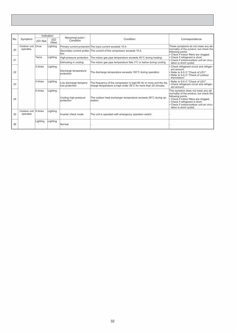
No. Symptom Indication
Abnormal point / Condition Condition Correspondence
LED1 (Red) LED2 (Yellow)
20Outdoor unit
operates. Once Lighting Primary current protection The input current exceeds 15 A. These symptoms do not mean any ab-
normality of the product, but check the following points. • Check if indoor fi lters are clogged. • Check if refrigerant is short. • Check if indoor/outdoor unit air circu-
lation is short cycled.
Secondary current protec-tion
The current of the compressor exceeds 15 A.
21Twice Lighting High-pressure protection The indoor gas pipe temperature exceeds 45°C during heating.
Defrosting in cooling The indoor gas pipe temperature falls 3°C or below during cooling.
22
3 times Lighting Discharge temperature protection The discharge temperature exceeds 100°C during operation.
• Check refrigerant circuit and refriger-ant amount.
• Refer to 9-5. "Check of LEV". • Refer to 9-5. "Check of outdoor
thermistors".
234 times Lighting Low discharge tempera-
ture protection The frequency of the compressor is kept 80 Hz or more and the dis-charge temperature is kept under 39°C for more than 20 minutes.
• Refer to 9-5. "Check of LEV". • Check refrigerant circuit and refriger-
ant amount.
24
5 times Lighting
Cooling high-pressure protection
The outdoor heat exchanger temperature exceeds 58°C during op-eration.
This symptom does not mean any ab-normality of the product, but check the following points. • Check if indoor fi lters are clogged. • Check if refrigerant is short. • Check if indoor/outdoor unit air circu-
lation is short cycled.
25Outdoor unit
operates 9 times Lighting
Inverter check mode The unit is operated with emergency operation switch. -
26Lighting Lighting
Normal - -

33
MUZ-GC50NA- C2
No. Symptom LED indication Abnormal point/ Condition Condition Correspondence
1
Outdoor unit does not oper-ate.
1-time fl ash every 2.5 seconds
Outdoor power sys-tem
Overcurrent protection stop is continuously performed 3 times within 1 minute after the compressor gets started, or failure of restart of compressor has repeated 24 times.
Reconnect connector of compres-sor.Refer to 9-5. "How to check in-verter/compressor".Check stop valve.
•
•
•
2Outdoor thermistors Discharge temperature thermistor, fi n temperature thermistor,
defrost thermistor, P.C. board temperature thermistor or ambi-ent temperature thermistor shorts or opens during compressor running.
Refer to 9-5. "Check of outdoor thermistors".
•
3Outdoor control sys-tem
Nonvolatile memory data cannot be read properly.
(The left lamp of OPERATION INDICATOR lamp of the indoor unit lights up or fl ashes 7-time.)
Replace inverter P.C. board.•
4 6-time fl ash 2.5 seconds OFF
Serial signal The communication fails between the indoor and outdoor unit for 3 minutes.
Refer to 9-5. "How to check mis-wiring and serial signal error.
•
5 11-time fl ash 2.5 seconds OFF
Stop valve/ Closed valve
Closed valve is detected by compressor current. Check stop valve.•
614-time fl ash 2.5 seconds OFF
Outdoor unit(Other abnormality)
Outdoor unit is defective. Refer to 9-2.2. "Flow chart of the detailed outdoor unit failure mode recall function".
•
7
'Outdoor unit stops and restarts 3 min-utes later' is repeated.
2-time fl ash 2.5 seconds OFF
Overcurrent protec-tion
Large current fl ows into intelligent power module. Reconnect connector of compres-sor.Refer to 9-5. "How to check in-verter/compressor".Check stop valve.
•
•
•
83-time fl ash 2.5 seconds OFF
Discharge tempera-ture overheat protec-tion
Temperature of discharge temperature thermistor exceeds 116°C, compressor stops. Compressor can restart if discharge temperature thermistor reads 100°C or less 3 minutes later.
Check refrigerant circuit and refrig-erant amount.Refer to 9-5. "Check of LEV".
•
•
94-time fl ash 2.5 seconds OFF
Fin temperature /P.C. board temperature thermistor overheat protection
Temperature of fi n temperature thermistor on the heat sink exceeds 75 ~ 88°C or temperature of P.C. board temperature thermistor on the inverter P.C.board exceeds 72 ~ 82°C.
Check around outdoor unit.Check outdoor unit air passage.Refer to 9-5. "Check of outdoor fan motor".
•••
105-time fl ash 2.5 seconds OFF
High pressure pro-tection
Indoor coil thermistor exceeds 70°C in HEAT mode. Defrost thermistor exceeds 70°C in COOL mode.
Check refrigerant circuit and refrig-erant amount.Check stop valve.
•
•
118-time fl ash 2.5 seconds OFF
Compressor syn-chronous abnormal-ity
The waveform of compressor current is distorted. Reconnect connector of compres-sor.Refer to 9-5. "How to check in-verter/compressor".
•
•
1210-time fl ash 2.5 seconds OFF
Outdoor fan motor Outdoor fan has stopped 3 times in a row within 30 seconds after outdoor fan start-up.
Refer to 9-5. "Check of outdoor fan motor.Refer to 9-5. "Check of inverter P.C. board.
•
•
13 12-time fl ash 2.5 seconds OFF
Each phase current of compressor
Each phase current of compressor cannot be detected nor-mally
Refer to 9-5. "How to check in-verter/compressor".
•
14 13-time fl ash 2.5 seconds OFF
DC voltage DC voltage of inverter cannot be detected normally. Refer to 9-5. "How to check in-verter/compressor".
•
15 Outdoor unit operates.
1-time fl ash 2.5 seconds OFF
Frequency drop by current protection
Current from power outlet reaches the protection current, and compressor frequency lowers.
The unit is normal, but check the following.Check if indoor fi lters are clogged.Check if refrigerant is short.Check if indoor/outdoor unit air cir-culation is short cycled.
•••
16
3-time fl ash 2.5 seconds OFF
Frequency drop by high pressure pro-tection
Temperature of indoor coil thermistor exceeds 55°C in HEAT mode, compressor frequency lowers.
Frequency drop by defrosting in COOL mode
Indoor coil thermistor reads 8°C or less in COOL mode, com-pressor frequency lowers.
17
4-time fl ash 2.5 seconds OFF
Frequency drop by discharge tempera-ture protection
Temperature of discharge temperature thermistor exceeds 111°C, compressor frequency lowers.
Check refrigerant circuit and refrig-erant amount.Refer to 9-5. "Check of LEV".Refer to 9-5. "Check of outdoor thermistors".
•
••
18Outdoor unit operates.
7-time fl ash 2.5 seconds OFF
Low discharge tem-perature protection
Temperature of discharge temperature thermistor has been 50°C or less for 20 minutes.
Refer to 9-5. "Check of LEV".Check refrigerant circuit and refrig-erant amount.
••
19
8-time fl ash 2.5 seconds OFF
PAM protection PAM : Pulse Amplitude Modulation
The overcurrent fl ows into IGBT (Insulated Gate Bipolar tran-sistor : TR821) or when the bus-bar voltage reaches 320 V or more, PAM stops and restarts.
This is not malfunction. PAM protec-tion will be activated in the following cases;1 Instantaneous power voltage drop.
(Short time power failure)2 When the power supply voltage is
high.
209-time fl ash 2.5 seconds OFF
Inverter check mode The connector of compressor is disconnected, inverter check mode starts.
Check if the connector of the com-pressor is correctly connected. Refer to 9-5. "How to check in-verter/compressor".
•
NOTE: 1. The location of LED is illustrated at the right fi gure. Refer to 9-6.1. 2. LED is lighted during normal operation.
The fl ashing frequency shows the number of times the LED blinks after every 2.5-second OFF.(Example) When the fl ashing frequency is “2”.
ON
OFF2.5-second OFF 2.5-second OFF
0.5-second ON 0.5-second ON
LEDFlashing →
Inverter P.C. board(Parts side)

34
9-4. TROUBLE CRITERION OF MAIN PARTSMUZ-GC25NA MUZ-GC35NA
Part name Check method and criterion Figure
Defrost thermistor (RT61) Measure the resistance with a tester.
Refer to 9-6. “Test point diagram and voltage”, 1. “Inverter P.C. board”, the chart of thermistor.
Discharge temperature thermistor (RT62)
Fin temperature thermistor (RT64)
Measure the resistance with a tester. Before measurement, hold the thermistor with your hands to warm it up.
Refer to 9-6. “Test point diagram and voltage”, 1. “Inverter P.C. board”, the chart of thermistor.
Compressor (MC)
Measure the resistance between terminals using a tester.(Winding temperature : -20 ~ 40°C)
Normal
GC25 GC35
U-VU-WV-W
1.58 ~ 2.03 Ω 1.43 ~ 1.84 Ω
Outdoor fan motor (MF)INNER FUSE126 +2
-2 °C CUT OFF
Measure the resistance between lead wires using a tester.(Part temperature : -20 ~ 40°C)
Color of the lead wire NormalWHT – BLK 212 ~ 272 ΩBLK – RED 234 ~ 300 Ω
R. V. coil (21S4)
Measure the resistance using a tester.(Part temperature : -20 ~ 40°C)
Normal
1.26 ~ 1.62 kΩ
Expansion valve coil (LEV)
Measure the resistance using a tester.(Part temperature : -20 ~ 40°C)
Color of lead wire NormalWHT – RED
38 ~ 50 ΩRED – ORNYLW – BRNBRN – BLU
2 3W
UV
1
WHT RED BLK
WHTREDBLK
FUSE
LEVWHTREDORN
YLW
BRN
BLU

35
MUZ-GC50NA MUZ-GC60NA MUZ-GC71NAPart name Check method and criterion Figure
Defrost thermistor (RT61)
Ambient temperature ther-mistor (RT65)
Outdoor heat exchanger tem-perature thermistor(RT68)
Measure the resistance with a tester.
Refer to 9-6. "Test point diagram and voltage", 1. "Inverter P.C. board" or 2. "Outdoor electronic control P.C. board”, the chart of thermistor.
Discharge temperaturethermistor(RT62)
Measure the resistance with a tester.Before measurement, hold the thermistor with your hands to warm it up.
Refer to 9-6. "Test point diagram and voltage", 1. "Inverter P.C. board" or 2. "Outdoor electronic control P.C. board", the chart of thermistor.
Fin temperaturethermistor (RT64)
Compressor (MC)
Measure the resistance between terminals using a tester.(Winding temperature : -10 ~ 40°C)
NormalGC50/60NA- C1 GC50/60NA- C2 GC71
0.40 ~ 0.49 Ω 0.86 ~ 1.06 Ω 1.29 ~ 1.49 Ω
Outdoor fan motor (MF)
Measure the resistance between lead wires using a tester.(Part temperature : -10 ~ 40°C)
Color of lead wire NormalRED – BLK
13.4 ~ 16.4 ΩBLK – WHTWHT – RED
R. V. coil
Measure the resistance using a tester. (Part temperature : -10 ~ 40°C)
NormalGC50NA- C2 GC60NA- C2 Other models
1.32 ~ 1.62 kΩ 2.6 ~ 3.3 kΩ
Linear expansion valve
Measure the resistance using a tester.(Part temperature : -10 ~ 40°C)
Color of lead wire NormalWHT – RED
37.4 ~ 53.9 ΩRED – ORNYLW – BRNBRN – BLU
High pressure switch (HPS) GC60NA- C2
GC71NA
Pressure (MPa) Normal3.7 ± 0.15 Close
4.8+0.05 -0.1 Open
W
UVWHT
RED
BLK
LEV
WHT
RED
YLW BRN
ORN
BLU
URED
WHT
BLK
V
W
(W)
(V)
(U)
36
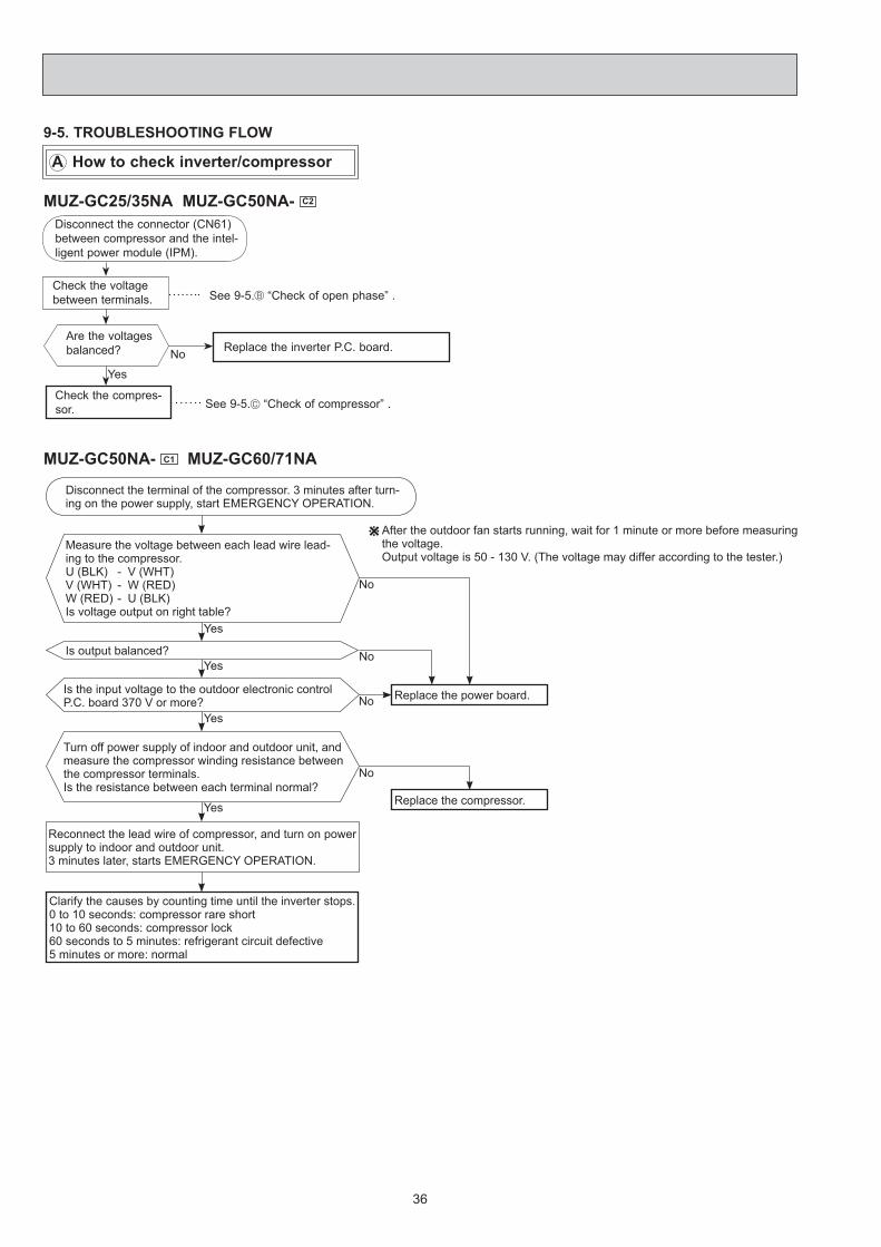
Check the compres-sor.
Check the voltage between terminals.
Disconnect the connector (CN61) between compressor and the intel-ligent power module (IPM).
Replace the inverter P.C. board.
See 9-5. “Check of compressor” .
No
See 9-5. “Check of open phase” .
Yes
Are the voltages balanced?
9-5. TROUBLESHOOTING FLOW
MUZ-GC25/35NA MUZ-GC50NA- C2
A How to check inverter/compressor
MUZ-GC50NA- C1 MUZ-GC60/71NA
Measure the voltage between each lead wire lead-ing to the compressor.U (BLK) - V (WHT)V (WHT) - W (RED)W (RED) - U (BLK)Is voltage output on right table?
Yes
No
Disconnect the terminal of the compressor. 3 minutes after turn-ing on the power supply, start EMERGENCY OPERATION.
After the outdoor fan starts running, wait for 1 minute or more before measuring the voltage.Output voltage is 50 - 130 V. (The voltage may differ according to the tester.)
Is output balanced?Yes
No
Is the input voltage to the outdoor electronic control P.C. board 370 V or more?
YesNo Replace the power board.
Turn off power supply of indoor and outdoor unit, and measure the compressor winding resistance between the compressor terminals. Is the resistance between each terminal normal?
Yes
No
Replace the compressor.
Reconnect the lead wire of compressor, and turn on power supply to indoor and outdoor unit. 3 minutes later, starts EMERGENCY OPERATION.
Clarify the causes by counting time until the inverter stops.0 to 10 seconds: compressor rare short 10 to 60 seconds: compressor lock60 seconds to 5 minutes: refrigerant circuit defective5 minutes or more: normal

37
B Check of open phase
MUZ-GC25/35NA MUZ-GC50NA- C2
● With the connector between the compressor and the intelligent power module disconnected, activate the inverter and check if the inverter is normal by measuring the balance of voltage between the terminals.
Output voltage is 50 - 130 V. (The voltage may differ according to the tester.)
<< Operation method>> Start cooling or heating operation by pressing EMERGENCY OPERATION switch on the indoor unit. (TEST RUN OPERA-
TION : Refer to 6-3.)<<Measurement point>> At 3 points BLK (U)-WHT (V) BLK (U)-RED (W) WHT(V)-RED (W)
NOTE: 1. Output voltage varies according to power supply voltage. 2. Measure the voltage by analog type tester. 3. During this check, LED of inverter P.C. board fl ashes 9 times. (Refer to 9-6.1.)
Measure AC voltage between the lead wires at 3 points.
C Check of compressor
MUZ-GC25/35NA MUZ-GC50NA- C2
Refer to 9-5. “Check of compressor operation time”. Does the compressor operate continuously?
OK.
No
Yes
Refer to 9-5. “Check of compressor winding”. Is the compressor normal? Replace the compressor.No
Yes
Refer to 9-5. "Check of compressor start failure".
MUZ-GC25/35NA● Disconnect the connector (CN61) between the compressor and intelligent power module, and measure the resistance be-
tween the compressor terminals.<<Measurement point>> At 3 points BLK-WHT BLK-RED WHT-RED<<Judgement>> Refer to 9-4. 0[Ω] ················Abnormal [short] Infinite[Ω] ·······Abnormal [open]
NOTE: Be sure to zero the ohmmeter before measurement.
Measure the resistance between the lead wires at 3 points.
D Check of compressor winding

38
E Check of compressor operation time
MUZ-GC25/35NA MUZ-GC50NA- C2
● Connect the compressor and activate the inverter. Then measure the time until the inverter stops due to over current.
<<Operation method>> Start heating or cooling operation by pressing EMERGENCY
OPERATION switch on the indoor unit. (TEST RUN OPERATION : Refer to 6-3.)<<Measurement>> Measure the time from the start of outdoor fan running to the
stop of compressor due to overcurrent.
Compressor starts
Abnormal(IPM failure)(Compressor winding short)Abnormal(Compressor lock out)(Starting defect)
Abnormal(Poor contact,)(Outdoor P.C. board defect)(Disconnected connector)
Abnormal(Refrigerant circuit defect)(Closed valve)
Normal
0 second
1 second
2 seconds
10 seconds
10 minutes
<<Judgement>>
F Check of compressor start failure
After the compressor is heated with a drier, does the compressor start? 1 Replace the compressor.
Compressor start failure. Activate pre-heat control.(Refer to 8-2. "PRE-HEAT CONTROL SETTING")
No
Yes
Does the compressor run for 10 seconds or more after it starts?
Check the refrigerant circuit.Check the stop valve.Yes
No
1Heat the compressor with a drier for about 20 minutes.Do not recover refrigerantgas while heating.
Heating part
Confi rm that 1~4 is normal.•Electrical circuit check
Contact of the compressor connector (including CN61)Output voltage of inverter P.C. board and balance of them (See 9-5. )Direct current voltage between DB61(+) and (-) on the inverter P.C.boardVoltage between outdoor terminal block S1-S2
1.2.3.4.
MUZ-GC25/35NA MUZ-GC50NA- C2

39
MUZ-GC25/35NA MUZ-GC50NA- C2
Thermistor Symbol Connector, Pin No. Board Defrost RT61 Between CN641 pin1 and pin2
Inverter P.C. boardDischarge temperature RT62 Between CN641 pin3 and pin4 Fin temperature RT64 Between CN642 pin1 and pin2 Ambient temperature (GC50) RT65 Between CN643 pin1 and pin2 Outdoor heat exchanger temperature (GC50) RT68 Between CN644 pin1 and pin3
MUZ-GC50NA- C1 MUZ-GC60/71NAThermistor Symbol Connector, Pin No. Board
Defrost RT61 Between CN661 pin 1 and pin 2 Outdoor electronic control P.C. board
Discharge temperature RT62 Between CN661 pin 3 and pin 4 Outdoor heat exchanger temperature RT68 Between CN661 pin 7 and pin 8 Ambient temperature RT65 Between CN663 pin 1 and pin 2 Fin temperature RT64 Between CN3 pin 1 and pin 2 Outdoor power board
G Check of outdoor thermistors
Replace the thermistor except RT64.When RT64 is abnormal, replace the inverter P.C. board or the outdoor power board.
Replace the inverter P.C. board or the outdoor electronic control P.C. board.
No
No
Is the thermistor normal? (Refer to 9-6.1. or 9-6.2.)
Reconnect the connector of thermistor.Turn ON the power supply and press EMERGENCY OPERATION switch.
Does the unit operate for 10 minutes or more without showing thermistor abnormality?
OK.(Cause is poor contact.)
Yes
Yes
Disconnect the connector of thermistor in the outdoor P.C. board (see below table), and measure the resistance of thermistor.
H Check of R.V. coil
First of all, measure the resistance of R.V. coil to check if the coil is defective. Refer to 9-4. In case CN721 is not connected or R.V. coil is open, voltage is generated between the terminal pins of the connector although any signal is not being transmitted to R.V. coil.
Check if CN721 is connected.
Unit operates COOL mode even if it is set to HEAT mode.
NoReplace the inverterP.C. board.
Is there 220 - 230 VAC between CN721 and on the inverter P.C. board 3
minutes after the power supply is turned ON?
Yes
Replace the 4-way valve.
Disconnect connector (CN61) between the compressor and the intelligent power module.Turn ON the power supply and press EMERGENCY OPERATION switch twice (HEAT mode).
YesReplace the inverterP.C. board.
Is there 220 - 230 VAC between CN721 and on the inverter P.C. board 3
minutes after the power supply is turned ON?
No
Replace the 4-way valve.
Unit operates HEAT mode even if it is set to COOL mode.Disconnect connector (CN61) between the compressor and the intelligent power module.Turn ON the power supply and press EMERGENCY OPERATION switch once (COOL mode).
MUZ-GC25/35NA MUZ-GC50NA- C2

40
MUZ-GC50NA- C1 MUZ-GC60/71NAHeating operation does not work.•
Is there voltage of 220 - 230 VAC between pin1 and pin 2 at connector CN912?
YesNo
Disconnect the lead wire leading to the compressor.3 minutes after turning on the power supply, start EMERGENCY OPERATION in HEAT mode.
1.2.
Turn off power supply of indoor and outdoor unit, and discon-nect the connector CN781 in the outdoor electronic control P.C. board.3 minutes after turning ON the power supply, start EMER-GENCY OPERATION in HEAT mode.
1.
2.Turn OFF power supply of indoor and outdoor unit.
Is there voltage 12 VDC be-tween the connector CN781 pin 5 (+) and pin 3 (-)? No
Disconnect the connec-tor CN912 in noise fi lter P.C. board. Is there normal resistance to R.V. coil?
No Replace the R.V. coil.
Replace the 4-way valve.Replace the noise fi lter P.C. board.
Yes
Replace the outdoor electronic control P.C. board.
Yes
Cooling operation does not work.•
Is there voltage of 220 - 230 VAC between pin1 and pin 2 at connector CN912?
Disconnect the lead wire leading to the compressor.3 minutes after turning on the power supply, start EMERGENCY OPERATION in COOL mode.
1.2.
Turn OFF power supply of indoor and outdoor unit, and disconnect the connector CN781 in the outdoor electronic control P.C. board.3 minutes after turning ON the power supply, start EMER-GENCY OPERATION in COOL mode.
1.
2.
Yes
Is there voltage 12 VDC between the connector CN781 pin 5 (+) and pin 3 (-)? No Replace the noise fi lter P.C. board.
Replace the outdoor electronic control P.C. board.
No Replace the 4-way valve.
If the connector CN912 is not connected or R.V. coil is open, voltage occurs between terminals even when the control is OFF.
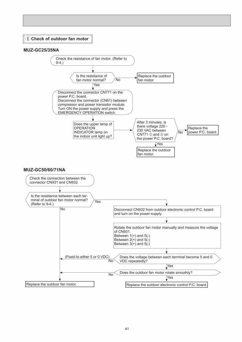
41
I Check of outdoor fan motor
Is the resistance between each ter-minal of outdoor fan motor normal? (Refer to 9-4.)
Check the connection between the connector CN931 and CN932.
Disconnect CN932 from outdoor electronic control P.C. board and turn on the power supply.
Rotate the outdoor fan motor manually and measure the voltage of CN931.Between 1(+) and 5(-)Between 2(+) and 5(-)Between 3(+) and 5(-)
Does the voltage between each terminal become 5 and 0 VDC repeatedly?
Does the outdoor fan motor rotate smoothly?
Replace the outdoor fan motor.
Yes
Yes
No(Fixed to either 5 or 0 VDC)
No
No
Yes
MUZ-GC50/60/71NA
Replace the outdoor electronic control P.C. board.
Check the resistance of fan motor. (Refer to 9-4.)
Is the resistance of fan motor normal?
Replace the outdoor fan motor.
Disconnect the connector CN771 on the power P.C. board.Disconnect the connector (CN61) between compressor and power transistor module.Turn ON the power supply and press theEMERGENCY OPERATION switch.
Does the upper lamp ofOPERATION INDICATOR lamp on the indoor unit light up?
After 3 minutes, is there voltage 220 - 230 VAC between CN771 and on the power P.C. board?
Replace the outdoor fan motor.
Replace the power P.C. board.
YesNo
Yes
No
MUZ-GC25/35NA
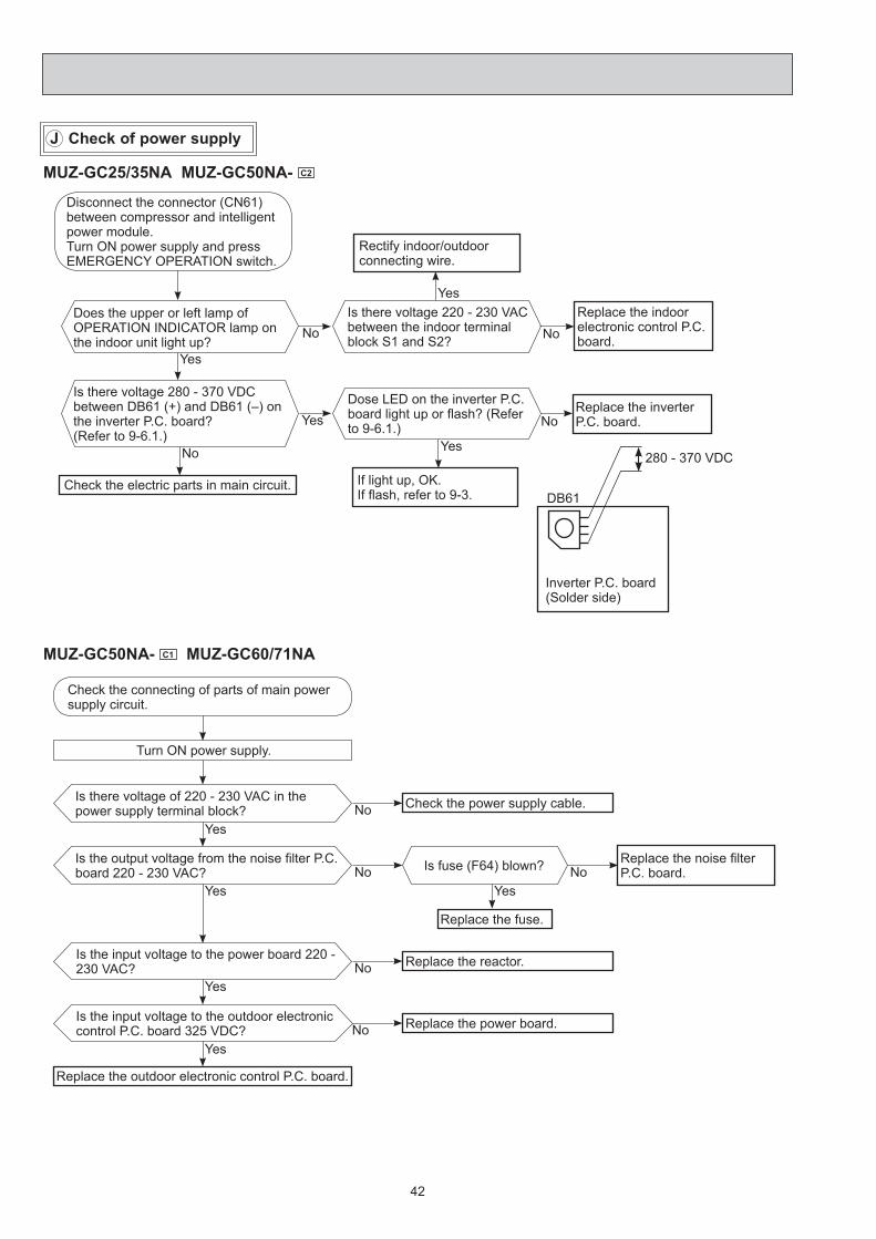
42
J Check of power supply
MUZ-GC25/35NA MUZ-GC50NA- C2
Is there voltage 220 - 230 VAC between the indoor terminal block S1 and S2? No
YesReplace the indoor electronic control P.C. board.
Rectify indoor/outdoor connecting wire.
Yes
If light up, OK.If fl ash, refer to 9-3.
Does the upper or left lamp of OPERATION INDICATOR lamp on the indoor unit light up?
Dose LED on the inverter P.C. board light up or fl ash? (Refer to 9-6.1.) No
Replace the inverter P.C. board.
Is there voltage 280 - 370 VDC between DB61 (+) and DB61 (–) on the inverter P.C. board?(Refer to 9-6.1.)
No
Check the electric parts in main circuit.
Yes
Yes
No
Disconnect the connector (CN61) between compressor and intelligent power module.Turn ON power supply and pressEMERGENCY OPERATION switch.
Inverter P.C. board(Solder side)
DB61
280 - 370 VDC
Is there voltage of 220 - 230 VAC in the power supply terminal block?
Check the connecting of parts of main power supply circuit.
Check the power supply cable.
Turn ON power supply.
Is the output voltage from the noise fi lter P.C. board 220 - 230 VAC?
Replace the noise fi lter P.C. board.
NoYes
NoYes
Is the input voltage to the power board 220 - 230 VAC? Replace the reactor.No
Yes
Is the input voltage to the outdoor electronic control P.C. board 325 VDC? Replace the power board.No
Replace the outdoor electronic control P.C. board.
Yes
Is fuse (F64) blown? NoYes
Replace the fuse.
MUZ-GC50NA- C1 MUZ-GC60/71NA

43
K Check of LEV (Expansion valve)
MUZ-GC50NA- C1 MUZ-GC60/71NATurn ON power supply to the outdoor unit after checking LEV coil is mounted to the LEV body securely.
Is "click - click" sound heard?Or, do you feel vibration of the LEV coil with a hand?
Disconnect the connector CN795. Is there normal resistance to LEV coil?
Normal
Replace the outdoor electronic control P.C. board.
Replace the LEV coil.
Yes
No
No
Yes
Replace the inverter P.C. board.No
Press OPERATE/STOP (ON/OFF) button of the remote controller (the set temperature is displayed) with the remote controller headed towards the indoor unit. 1
Expansion valve operates in full-opening direction.
OK
NOTE : After check of LEV, do the undermentioned operations. 1. Turn OFF the power supply and turn ON it again. 2. Press RESET button on the remote controller.
1. Regardless of normal or abnormal condition, a short beep is emitted once the signal is received.
Measure each voltage between connector pins of CN724 on the inverter P.C. board.1. Pin (-) — Pin (+)2. Pin (-) — Pin (+)3. Pin (-) — Pin (+)4. Pin (-) — Pin (+)Is there about 3 ~ 5 VAC between each?NOTE: Measure the voltage by an analog
tester.
Properly fi x the LEV coil to the expansion valve.
Replace the LEV coil.
Replace the expansion valve.
Is LEV coil properly fi xed to the expansion valve?
Does the resistance of LEV coil have the characteristics?(Refer to 9-4.)
Do you hear the expansion valve "click, click·······"?Do you feel the expansion valve vibrate on touching it ?
Turn ON the power supply.<Preparation of the remote controller>
While pressing both OPERATION SELECT button and TOO COOL button on the remote controller at the same time, press RESET button. First, release RESET button.
And release the other two buttons after all LCD except the set temperature in operation display section of the remote controller is displayed after 3 seconds.
Yes
No
No
Yes
NoYes
Yes
MUZ-GC25/35NA MUZ-GC50NA- C2

44
Check the outdoor fan motor. (Refer to 9-5. .)
Is the fuse (F901) blown on the in-verter P.C. board?
Check the connection of the connectors (CN931, CN932) of the outdoor fan mo-tor. If the connection is poor, make it correct.
Operate the outdoor unit by starting EMERGENCY OPERATION.
Check the LED indication on the in-verter P.C. board.Does the LED fl ash 10 times?
Replace the inverter P.C. board.
Check the corresponding parts following LED indication.(Refer to 9-3.)
YesNo
Yes(10-time fl ash)
No
MUZ-GC50NA- C2
L Check of inverter P.C. board
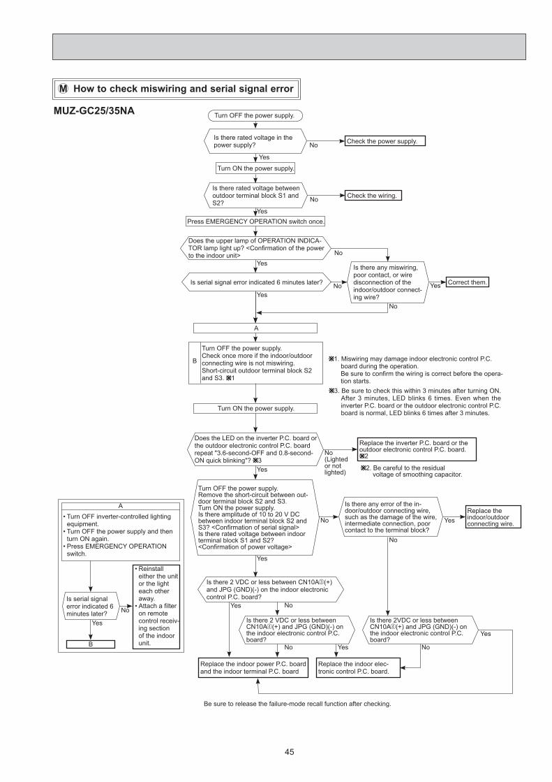
45
M How to check miswiring and serial signal error
Replace the indoor power P.C. board and the indoor terminal P.C. board
Turn OFF the power supply.
Is there rated voltage in the power supply?
Yes
No
Turn ON the power supply.
Check the power supply.
Is there rated voltage between outdoor terminal block S1 and S2? No Check the wiring.
Press EMERGENCY OPERATION switch once.
Does the upper lamp of OPERATION INDICA-TOR lamp light up? <Confi rmation of the power to the indoor unit>
YesNo
Is serial signal error indicated 6 minutes later?
YesNo
Is there any miswiring, poor contact, or wire disconnection of the indoor/outdoor connect-ing wire?
Yes Correct them.
No
A
Turn OFF the power supply.Check once more if the indoor/outdoor connecting wire is not miswiring.Short-circuit outdoor terminal block S2 and S3. 1
B 1. Miswiring may damage indoor electronic control P.C. board during the operation.Be sure to confi rm the wiring is correct before the opera-tion starts.
Turn ON the power supply.
Does the LED on the inverter P.C. board or the outdoor electronic control P.C. board repeat "3.6-second-OFF and 0.8-second-ON quick blinking"? 3
Yes
No(Lighted or not lighted)
Replace the inverter P.C. board or the outdoor electronic control P.C. board.
2
2. Be careful to the residual voltage of smoothing capacitor.
Turn OFF the power supply.Remove the short-circuit between out-door terminal block S2 and S3.Turn ON the power supply.Is there amplitude of 10 to 20 V DC between indoor terminal block S2 and S3? <Confi rmation of serial signal>Is there rated voltage between indoor terminal block S1 and S2?<Confi rmation of power voltage>
Yes
No
Is there any error of the in-door/outdoor connecting wire, such as the damage of the wire, intermediate connection, poor contact to the terminal block?
YesReplace the indoor/outdoor connecting wire.
Is there 2 VDC or less between CN10A (+) and JPG (GND)(-) on the indoor electronic control P.C. board?
No
NoYes
Be sure to release the failure-mode recall function after checking.
Yes
Turn OFF inverter-controlled lighting equipment.Turn OFF the power supply and then turn ON again.Press EMERGENCY OPERATION switch.
•
•
•
A
Is serial signal error indicated 6 minutes later?
B
Yes
Reinstall either the unit or the light each other away.Attach a fi lter on remote control receiv-ing section of the indoor unit.
•
•No
3. Be sure to check this within 3 minutes after turning ON. After 3 minutes, LED blinks 6 times. Even when the inverter P.C. board or the outdoor electronic control P.C. board is normal, LED blinks 6 times after 3 minutes.
Is there 2VDC or less between CN10A (+) and JPG (GND)(-) on the indoor electronic control P.C. board?
Is there 2 VDC or less between CN10A (+) and JPG (GND)(-) on the indoor electronic control P.C. board?
Replace the indoor elec-tronic control P.C. board.
No Yes No
Yes
MUZ-GC25/35NA

46
MUZ-GC50/60/71NA
Turn OFF the power supply.
Is there rated voltage in the power supply?
YesNo
Turn ON the power supply.
Check the power supply.
Is there rated voltage between outdoor termi-nal block S1 and S2? No Check the wiring.
Press EMERGENCY OPERATION switch once.
Does the left lamp of OPERATION INDICA-TOR lamp light up? <Confi rmation of the power to the indoor unit>
YesNo
Is serial signal error indicated 6 minutes later?Yes
No
Is there any miswiring, poor contact, or wire disconnection of the indoor/outdoor connect-ing wire?
Yes Correct them.
No
A
Turn OFF the power supply.Check once more if the indoor/outdoor connecting wire is not miswiring.Short-circuit outdoor terminal block S2 and S3. 1
B1. Miswiring may damage indoor electronic control P.C. board
during the operation. Be sure to confi rm the wiring is correct before the operation
starts.3. Be sure to check this within 3 minutes after turning ON. After
3 minutes, LED blinks 6 times. Even when the inverter P.C. board or the outdoor electronic control P.C. board is normal, LED blinks 6 times after 3 minutes.
Turn ON the power supply.
Does the LED on the inverter P.C. board or the outdoor electronic control P.C. board repeat "3.6-second-OFF and 0.8-second-ON quick blinking"? 3
Yes
No(Lighted or not lighted)
Replace the inverter P.C. board or the outdoor electronic control P.C. board.
22. Be careful to the residual voltage of smoothing
capacitor.
Turn OFF the power supply.Remove the short-circuit between outdoor terminal block S2 and S3.Turn ON the power supply.Is there amplitude of 10 to 20 VDC between outdoor terminal block S2 and S3? <Confi rmation of serial signal>
Yes
No
Is there any error of the in-door/outdoor connecting wire, such as the damage of the wire, intermediate connection, poor contact to the terminal block?
YesReplace the indoor/outdoor connecting wire.
Turn OFF inverter-controlled lighting equipment.Turn OFF the power supply and then turn ON again.Press EMERGENCY OPERATION switch.
•
•
•
A
Is serial signal error indicated 6 minutes later?
B
Yes
Reinstall either the unit or the light each other away.Attach a fi lter on remote control receiv-ing section of the indoor unit.
•
•No
Is there rated voltage between indoor terminal block S1 and S2?<Confi rmation of power voltage>
No
No
Is there any error of the in-door/outdoor connecting wire, such as the damage of the wire, intermediate connection, poor contact to the terminal block?
YesReplace the indoor/outdoor connecting wire.
No
Replace the indoor electronic control P.C. board.
Yes
Be sure to release the failure-mode recall function after checking.
Yes

47
MUZ-GC60NA- C2 MUZ-GC71NA
N Check of HPS
1. Disconnect the connector CN681 in the outdoor electronic control P.C. board.2. Check the resistance of HPS 1 minute after the outdoor unit power supply was turned OFF.
Check the resistance between each terminal.
Is HPS protection displayed immediately after compressor starts?
Replace HPS.
Replace the outdoor electronic control P.C. board.
Normal
Infi nity
No
0 Ω
Yes
Reconnect CN681.Turn ON power supply to the indoor and outdoor unit.3 minutes later, start EMERGENCY OPERATION.

48
O Electromagnetic noise enters into TV sets or radios
YesIs the unit earthed?
No Earth the unit.
Yes
Is the distance between the antennas and the indoor unit within 3 m, or is the distance between the antennas and the outdoor unit within 3 m?
No
Extend the distance between the antennas and the indoor unit, and/or the antennas and the outdoor unit.
Is the distance between the TV sets or radios and the indoor unit within 1 m, or is the distance between the TV sets or radios and the outdoor unit within 3 m?
Yes
Extend the distance between the TV sets and/or radios and the indoor unit, or the TV sets or radios and the outdoor unit.
Are the antennas damaged?Is the coaxial cable damaged?Is there any poor contact in the anten-na wiring?
Yes
No
No
Replace or repair the antenna.Replace or repair the coaxial cable.
Is the indoor/outdoor connecting wire of the air conditioner and the wiring of the antennas close? Yes
Extend the distance between the indoor/outdoor connecting wire of the air conditioner and the wir-ing of the antennas.
No
Even if all of the above conditions are fulfi lled, the electromagnetic noise may enter, depending on the electric fi eld strength or the installation condition (combination of specifi c conditions such as antennas or wiring).Check the following before asking for service.1. Devices affected by the electromagnetic noise TV sets, radios (FM/AM broadcast, shortwave)2. Channel, frequency, broadcast station affected by the electromagnetic noise3. Channel, frequency, broadcast station unaffected by the electromagnetic noise4. Layout of ; indoor/outdoor unit of the air conditioner, indoor/outdoor wiring, earth wire, antennas, wiring from antennas, receiver5. Electric fi eld intensity of the broadcast station affected by the electromagnetic noise6. Presence or absence of amplifi er such as booster7. Operation condition of air conditioner when the electromagnetic noise enters in
1) Turn OFF the power supply once, and then turn ON the power supply. In this situation, check for the electromagnetic noise.
2) Within 3 minutes after turning ON the power supply, press OPERATE/STOP (ON/OFF) button on the remote controller for power ON, and check for the electromagnetic noise.
3) After a short time (3 minutes later after turning ON), the outdoor unit starts running. During operation, check for the electromagnetic noise.
4) Press OPERATE/STOP (ON/OFF) button on the remote controller for power OFF, when the outdoor unit stops but the indoor/outdoor communication still runs on. In this situation, check for the electromagnetic noise.

49
-20 -10 0 10 20 30 400
10
20
30
40
50
60
70
80
90
100
Temperature(°C)
Defrost thermistor(RT61)
Temperature(°C)
Discharge temperature thermistor(RT62)
0 10 20 30 40 50 60 70 80 90 100 110 1200
100
200
300
400
500
600
700
0 10 20 30 40 50 60 70 800
20
40
60
80
100
120
140
160
180
200
Temperature(°C)
Fin temperature thermistor(RT64)
Res
ista
nce(
k )
Res
ista
nce(
k )
Res
ista
nce(
k )
1. Inverter P.C. boardMUZ-GC25NA MUZ-GC35NA
9-6. TEST POINT DIAGRAM AND VOLTAGE
Back side of unit
Output to drive outdoor fan motor (CN771)
Fin
tem
pera
ture
ther
mis
tor/R
T64
(CN
642)
Dis
char
ge te
mpe
ratu
re
ther
mis
tor/R
T62
(CN
641)
Def
rost
ther
mis
tor/R
T61
(CN
641)
LEVconnector(CN724)
DB61220-230V AC
Jum
per w
ire fo
r cha
nge
in d
efro
st s
ettin
g (J
S)
Front side of unit
DB61280V ~ 370VDC
Smoothing capacitor(C62)
Smoothing capacitor(C61)
Output to drivecompressor(LDW,LDV,LDU)
LED monitorlamp
R.V.coil(CN721)
(+) (-)
Fuse(F701)
Fuse(F801)
Jum
per w
ire fo
r pre
-hea
t co
ntro
l set
ting
(JK
)
Varistor(NR61)Varistor
(NR63)
Varistor(NR62)

50
-20 -10 0 10 20 30 400
10
20
30
40
50
60
70
80
90
100
Temperature( )
Defrost thermistor(RT61)Ambient temperature thermistor(RT65)Outdoor heat exchanger temperature thermistor(RT68)
Temperature( )
Discharge temperature thermistor(RT62)
0 10 20 30 40 50 60 70 80 90 100 110 1200
100
200
300
400
500
600
700
0 10 20 30 40 50 60 70 800
20
40
60
80
100
120
140
160
180
200
Temperature( )
Fin temperature thermistor(RT64)
Res
ista
nce(
k )
Res
ista
nce(
k )
Res
ista
nce(
k )
MUZ-GC50NA- C2
Back side of unit
Fin
tem
pera
ture
ther
mis
tor /
RT6
4(C
N64
2)
Am
bien
t tem
pera
ture
th
erm
isto
r /R
T65
(CN
643)
Dis
char
ge te
mpe
ratu
re
ther
mis
tor /
RT6
2(C
N64
1)
Def
rost
ther
mis
tor
/RT6
1(C
N64
1)
LEV
con
nect
or (C
N72
4)
DB61DC 260 - 300 V
Front side of unit
AC 220 - 230 V
Smoothing capacitor(C62)
Output to drive com-pressor(LDU,LDV,LDW)
(+)(-)
Fuse (F701)250 V 3.15 A
Smoothing capacitor(C61)
Smoothing capacitor(C63)
Fuse (F801)250 V 3.15 A
Fuse (F901)250 V 3.15 A
R.V.coil(CN721)220 - 230 VAC
Jum
per w
ire fo
r cha
ngin
g de
frost
set
ting
(JS
)
Out
put t
o dr
ive
outd
oor
fan
mot
or (C
N93
2)
AC 220 -230 V
Out
door
hea
t exc
hang
erte
mpe
ratu
re th
erm
isto
r /R
T68(
CN
644)
Jum
per w
ire fo
r pre
-hea
t co
ntro
l set
ting
(JK
)
Sig
nal o
f ou
tdoo
r fan
m
otor
(CN
931)

51
2. Outdoor electronic control P.C. boardMUZ-GC50NA- C1 MUZ-GC71NAMUZ-GC60NA
LED 1
LED 2
CN801310V DC
~370V DC
Input
( (CN
932
20-9
0V A
C
GN
D5V
5V D
Cpu
lse
wav
e
( To fa
nm
otor
Def
rost
ther
mis
tor (
RT6
1)D
isch
arge
tem
pera
ture
ther
mis
tor (
RT6
2)O
utdo
or h
eat e
xcha
nger
te
mpe
ratu
re th
erm
isto
r (R
T68)
( ((+)
(–)
(+)
Rush
curre
nt re
lay (–
)R
.V. c
oil (
–)
( 12V
DC
15V
15V
(+)
(–)
CN
931
(C
N66
1
CN
701
Sig
nal t
rans
mis
sion
(To
pow
er b
oard
)5V
DC
pul
se w
ave
(+)
(–)
(
GN
DC
N70
2S
igna
l rec
eptio
n(F
rom
pow
er b
oard
)5V
DC
pul
se w
ave
GND
(pow
er b
oard
)
CN
781
CN
795
12V
DC
puls
e w
ave
LEV
(
(
( ( (
-20 -10 0 10 20 30 40
100
90
80
70
60
50
40
30
20
10
0
0 10 20 30 40 50 60 70 80
200
180
160
140
120
100
80
60
40
20
0
Res
ista
nce
(k )
Res
ista
nce
(k )
Temperature (°C)
Temperature (°C)
Defrost thermistor (RT61)Ambient temperature thermistor (RT65)Outdoor heat exchanger temperature thermistor (RT68)Fin temperature thermistor (RT64)
0 10 20 30 40 50 60 70 80 90 100 110 120
700
600
500
400
300
200
100
0
Res
ista
nce
(k
)
Temperature (°C)
Discharge temperature thermistor (RT62)
F801 FUSE
3.15A/250V
( Ambi
ent t
empe
ratu
reth
erm
isto
r (R
T65)
CN
663
Serial signal 5 - 10 VDC
CN601
220 - 230 VAC Input
High pressure switch
MUZ-GC60NA- C2
MUZ-GC71NACN681
( (
(

52
{CN912R.V. coil 220-230V AC
220-230V ACInput
220-230V ACOutput
{
CN901To electroniccontrol P.C. board
MUZ-GC50NA- C1 MUZ-GC60NA MUZ-GC71NA
F64 FUSE2A/250V
F911 FUSE1A/250V
3. Noise filter P.C. board
CN902To powerboard {
CN903To powerboard
{CN61220-230V AC Output
NR64 VARISTOR

53
MUZ-GC50NA- C1 MUZ-GC60NA MUZ-GC71NA4. Outdoor power board
310-370V DCOutput (Red)
(White)
Connect to the compressorVoltage among phases: 5V to 180V
Connect to the earth
CN5Primary current detection(Connect to the noise filter)
CN2Connect to the controller board(+)1-5(–): Signal transmission (To electronic control P.C. board) 5V DC pulse wave(+)2-5(–): Zero cross signal 3-4 : Not used(+)6-5(–): 15V(+)7-5(–): 15V
(+)
(–)
Signal reception (From electronic control P.C. board) 5V DC pulse wave
)
CN3Fin temperature thermistor RT64
1
3
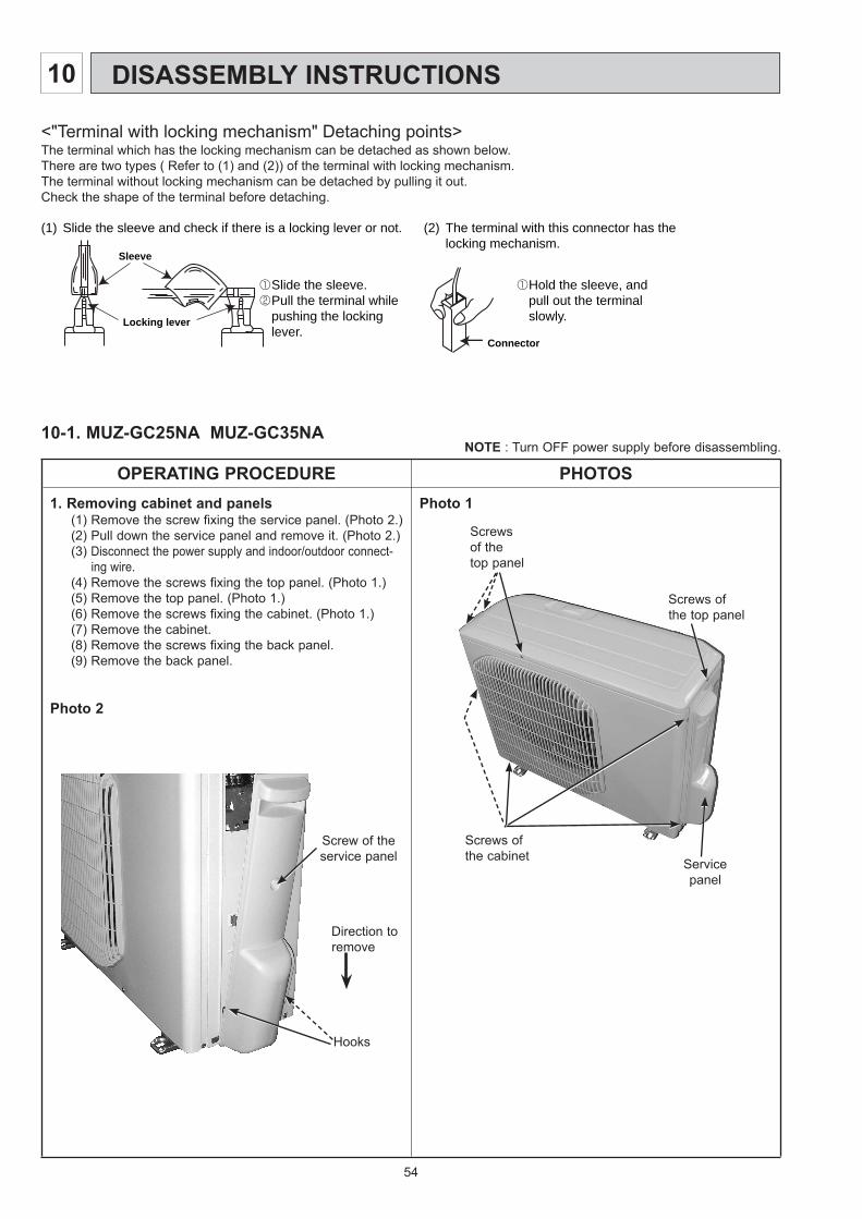
54
10-1. MUZ-GC25NA MUZ-GC35NANOTE : Turn OFF power supply before disassembling.
OPERATING PROCEDURE PHOTOS1. Removing cabinet and panels
(1) Remove the screw fixing the service panel. (Photo 2.)(2) Pull down the service panel and remove it. (Photo 2.)(3) Disconnect the power supply and indoor/outdoor connect-
ing wire.(4) Remove the screws fixing the top panel. (Photo 1.)(5) Remove the top panel. (Photo 1.)(6) Remove the screws fixing the cabinet. (Photo 1.)(7) Remove the cabinet.(8) Remove the screws fixing the back panel.(9) Remove the back panel.
Photo 2
Photo 1
Screws of the cabinet
(1) Slide the sleeve and check if there is a locking lever or not. (2) The terminal with this connector has the locking mechanism.
Slide the sleeve.Pull the terminal while pushing the lockinglever.
Hold the sleeve, and pull out the terminal slowly.
Connector
Sleeve
Locking lever
Service panel
Screws of the top panel
Screws of the top panel
Screw of theservice panel
Direction to remove
<"Terminal with locking mechanism" Detaching points>The terminal which has the locking mechanism can be detached as shown below.There are two types ( Refer to (1) and (2)) of the terminal with locking mechanism.The terminal without locking mechanism can be detached by pulling it out.Check the shape of the terminal before detaching.
HooksHooks
10 DISASSEMBLY INSTRUCTIONS
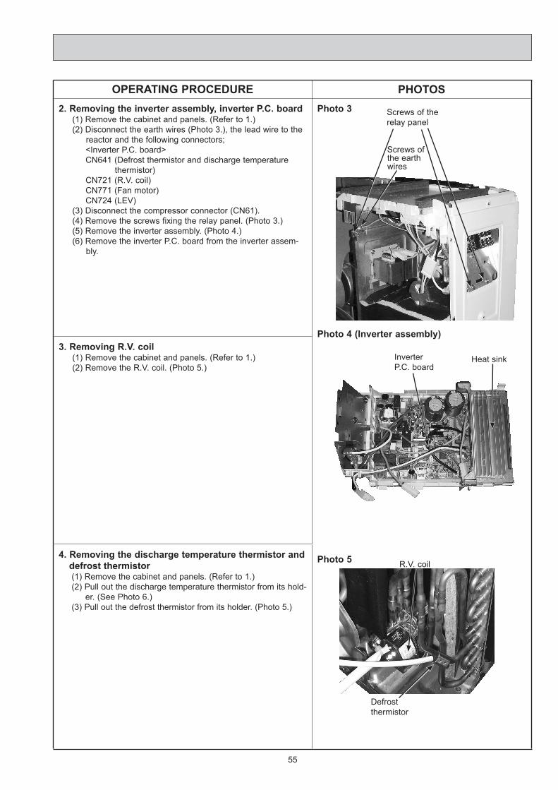
55
OPERATING PROCEDURE PHOTOS2. Removing the inverter assembly, inverter P.C. board
(1) Remove the cabinet and panels. (Refer to 1.)(2) Disconnect the earth wires (Photo 3.), the lead wire to the
reactor and the following connectors;<Inverter P.C. board>CN641 (Defrost thermistor and discharge temperature
thermistor)CN721 (R.V. coil)CN771 (Fan motor)CN724 (LEV)
(3) Disconnect the compressor connector (CN61).(4) Remove the screws fixing the relay panel. (Photo 3.)(5) Remove the inverter assembly. (Photo 4.)(6) Remove the inverter P.C. board from the inverter assem-
bly.
Photo 3
Photo 4 (Inverter assembly)
Photo 5
3. Removing R.V. coil (1) Remove the cabinet and panels. (Refer to 1.)(2) Remove the R.V. coil. (Photo 5.)
4. Removing the discharge temperature thermistor and defrost thermistor(1) Remove the cabinet and panels. (Refer to 1.)(2) Pull out the discharge temperature thermistor from its hold-
er. (See Photo 6.)(3) Pull out the defrost thermistor from its holder. (Photo 5.)
Defrostthermistor
R.V. coil
Screws of the earth wires
Screws of therelay panel
Heat sinkInverterP.C. board
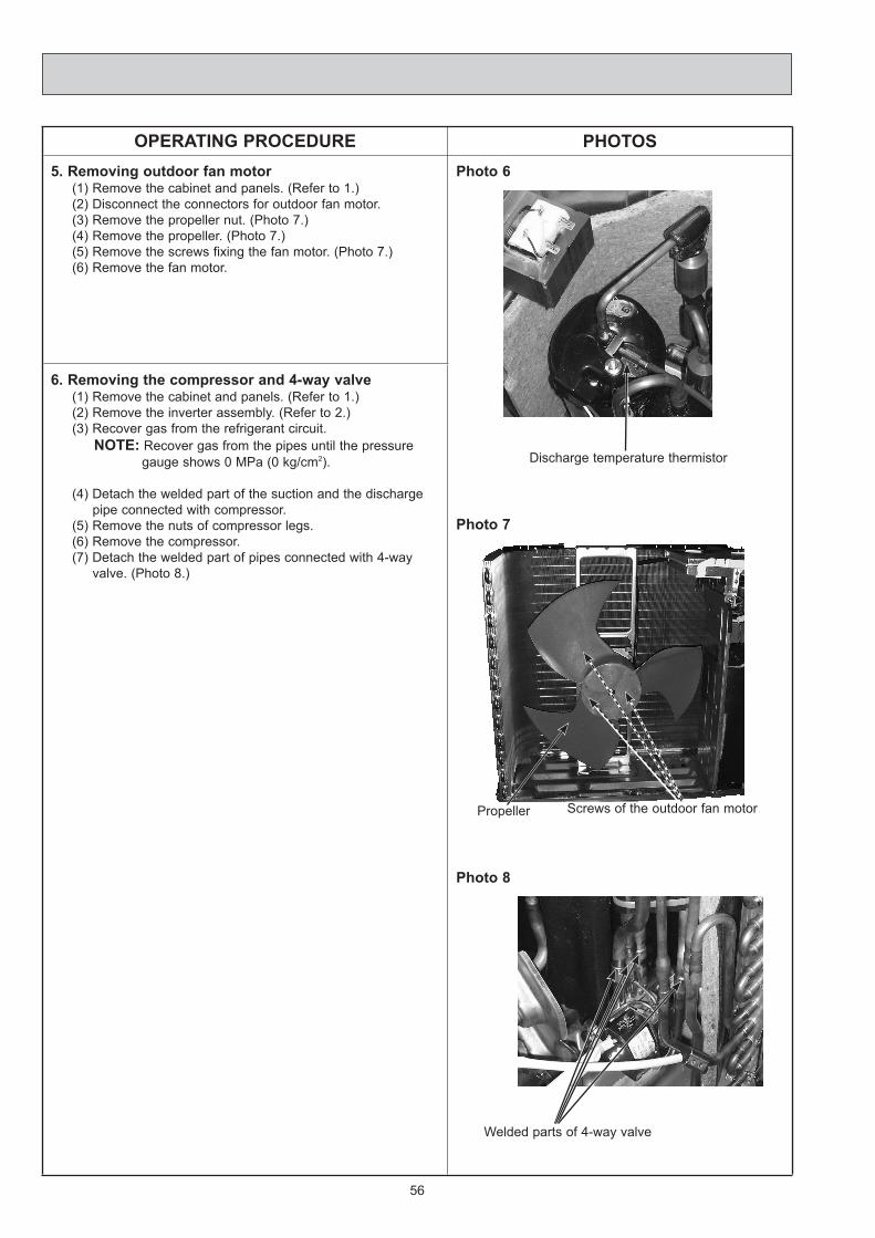
56
OPERATING PROCEDURE PHOTOS5. Removing outdoor fan motor
(1) Remove the cabinet and panels. (Refer to 1.)(2) Disconnect the connectors for outdoor fan motor.(3) Remove the propeller nut. (Photo 7.)(4) Remove the propeller. (Photo 7.)(5) Remove the screws fixing the fan motor. (Photo 7.)(6) Remove the fan motor.
Photo 6
Photo 7
Photo 8
6. Removing the compressor and 4-way valve(1) Remove the cabinet and panels. (Refer to 1.)(2) Remove the inverter assembly. (Refer to 2.)(3) Recover gas from the refrigerant circuit.
NOTE: Recover gas from the pipes until the pressure gauge shows 0 MPa (0 kg/cm2).
(4) Detach the welded part of the suction and the discharge pipe connected with compressor.
(5) Remove the nuts of compressor legs.(6) Remove the compressor.(7) Detach the welded part of pipes connected with 4-way
valve. (Photo 8.)
Propeller Screws of the outdoor fan motor
Welded parts of 4-way valve
Discharge temperature thermistor

57
10-2. MUZ-GC50NA MUZ-GC60NA MUZ-GC71NANOTE : These photos are MUZ-GC71NA. Other models
are almost the same as MUZ-GC71NA. Turn OFF power supply. before disassembling.
OPERATING PROCEDURE PHOTOS1. Removing the cabinet
(1) Remove the screws of the service panel.(2) Remove the screws of the top panel.(3) Remove the screw of the valve cover.(4) Remove the service panel.(5) Remove the top panel.(6) Remove the valve cover.(7) Disconnect the power supply and indoor/outdoor connect-
ing wire.(8) Remove the screws of the cabinet.(9) Remove the cabinet.(10) Remove the screws of the back panel.(11) Remove the back panel.
Photo 3
Photo 1
Photo 2
Screw of the top panel
Screws of the cabinet
Screws of the cabinet
Screw of the motor support
Set screws of the back panel
Screws of the back panel
Screws of the top panel
Screws of the cabinet
Screw of the service panel
Screw of the valve cover
Set screws of the back panel

58
OPERATING PROCEDURE PHOTOSMUZ-GC50NA- C1 MUZ-GC60/712. Removing the inverter assembly, inverter P.C. board
and power board (1) Remove the top panel, cabinet and service panel. (Refer to
1.)(2) Remove the back panel. (Refer to 1.)(3) Disconnect the following connectors;
<Electronic control P.C. board>CN931 and CN932 (Fan motor)CN795 (LEV)CN661 (Discharge temperature thermistor, defrost thermis-
tor and outdoor heat exchanger temperature ther-mistor)
CN663 (Ambient temperature thermistor)<Noise filter P.C. board>CN912 (R.V. coil)
(4) Remove the compressor connector.(5) Remove the screws fixing the relay panel.(6) Remove the inverter assembly.(7) Disconnect all connectors and lead wires on the electronic
control P.C. board.(8) Remove the electronic control P.C. board from the inverter
assembly.(9) Remove the screws fixing the power board assembly.(10) Disconnect all connectors and lead wires on the power
board.(11) Remove the power board from the inverter assembly.(12) Disconnect all connectors and lead wires on the noise filter
P.C. board.(13) Remove the noise filter P.C. board from the inverter assem-
bly.
Photo 4 (MUZ-GC50NA- C1 MUZ-GC60/71)
Photo 5 (MUZ-GC50NA- C2 )
Photo 6 (Inverter assembly : MUZ-GC50NA- C2 )
MUZ-GC50NA- C2
3. Removing the inverter assembly, inverter P.C. board(1) Remove the cabinet and panels. (Refer to 1.)(2) Disconnect the lead wire to the reactor and the following
connectors; <Inverter P.C. board>
CN721 (R.V.coil)CN932 (Fan motor)CN641 (Defrost thermistor and discharge temperature ther-
mistor)CN643 (Ambient temperature thermistor) CN644 (Outdoor heat exchanger temperature thermistor)CN724 (LEV)
(3) Remove the compressor connector (CN61).(4) Remove the screws fixing the relay panel. (Photo 5)(5) Remove the inverter assembly. (Photo 6)(6) Remove the screw of the earth wire and screw of the
T.B.support. (Photo 6)(7) Remove the screw of the PB fixture.(8) Remove the relay panel from the PB support.(9) Remove the inverter P.C. board from the inverter assembly.
Screws of the relay panel
Screws of the power board assembly
Heat sink Inverter P.C. board
Screw of the earth wire
T.B.support
Screw of the T.B.support
Screws of the relay panel
Screws of the reactor
Hook of the PB support PB support
Hook of the PB support Relay panel
Screw of the PB fixture

59
OPERATING PROCEDURE PHOTOS4. Removing R.V. coil
(1) Remove the top panel, cabinet and service panel. (Refer to 1.)
(2) Remove the back panel. (Refer to 1.)(3) Disconnect the following connectors;
MUZ-GC50NA- C1 MUZ-GC60/71<Noise filter P.C. board>CN912 (R.V. coil)
MUZ-GC50NA- C2
<Inverter P.C. board>CN721 (R.V. coil)
(4) Remove the R.V. coil. (Photo 11)
Photo 7
Photo 8
5. Removing the defrost thermistor, discharge tempera-ture thermistor, outdoor heat exchanger temperature thermistor and ambient temperature thermistor(1) Remove the top panel, cabinet and service panel. (Refer to
1.)(2) Remove the back panel. (Refer to 1.)(3) Disconnect the following connectors;
<Electronic control P.C. board>CN661 (Discharge temperature thermistor, defrost thermis-
tor and outdoor heat exchanger temperature ther-mistor)
CN663 (Ambient temperature thermistor)(4) Pull out the defrost thermistor from its holder. (Photo 8)(5) Pull out the discharge temperature thermistor from its hold-
er. (Photo 7)(6) Pull out the outdoor heat exchanger temperature thermistor
from its holder. (Photo 8)(7) Pull out the ambient temperature thermistor from its holder.
(Photo 8)
6. Removing outdoor fan motor(1) Remove the top panel, cabinet and service panel. (Refer to
1.)(2) Remove the back panel. (Refer to 1.)(3) Disconnect the following connectors;
MUZ-GC50NA- C1 MUZ-GA60/71<Electronic control P.C. board>CN931 and CN932 (Fan motor)
MUZ-GC50NA- C2
<Inverter P.C. board>CN931 and CN932 (Fan motor)
(4) Remove the propeller.(5) Remove the screws fixing the fan motor.(6) Remove the fan motor.
Photo 9Propeller
Screws of the outdoor fan motor
Defrostthermistor
Discharge temperature thermistor
Outdoor heat exchanger temperature thermistor
Ambient tem-peraturethermistor

60
OPERATING PROCEDURE PHOTOS7. Removing the compressor and 4-way valve
(1) Remove the top panel, cabinet and service panel. (Refer to 1.)
(2) Remove the back panel. (Refer to 1.)(3) Remove the inverter assembly. (Refer to 2.)(4) Recover gas from the refrigerant circuit.NOTE: Recover gas from the pipes until the pressure gauge
shows 0 kg/cm2 (0 MPa).(5) Detach the welded part of the suction and the discharge
pipe connected with compressor. (Photo 11)(6) Remove the compressor nuts.
(7) Remove the compressor.(8) Detach the welded part of 4-way valve and pipe. (Photo 10)
Photo 10
Photo 11
8. Removing the reactor(1) Remove the top panel, cabinet, service panel and the back
panel. (Refer to 1.)(2) Disconnect the reactor lead wire.(3) Remove the screws of the reactor, and remove the reactor.
(Photo 5,12)
Photo 12 (MUZ-GC50NA- C1 MUZ-GC60/71)
Welded parts of 4-way valve
Welded part of the dis-charge pipe
R.V. coil
Welded part of the suction pipe
Screws of the reactor

61

62

63

HEAD OFFICE: TOKYO BLDG., 2-7-3, MARUNOUCHI, CHIYODA-KU, TOKYO 100-8310, JAPAN
Copyright 2007 MITSUBISHI ELECTRIC ENGINEERING CO.,LTDDistributed in Aug. 2008. No. OBH482 REVISED EDITION-C 6Distributed in Jun. 2008. No. OBH482 REVISED EDITION-B 6Distributed in Nov. 2007. No. OBH482 REVISED EDITION-A 6Distributed in Mar. 2007. No. OBH482 6Made in Japan
New publication, effective Aug. 2008Specifications subject to change without notice.
TM


