

Overview of Network
Protocols, Services & LayeringOSI Reference Model
TCP/IP ArchitectureError Detection and Correction

What is Computer Networks?
A collection of autonomous computers interconnected by a single technology Interconnected via:
Copper wireFiber opticsMicrowavesInfraredCommunication satellites, etc.

Protocols, Services & Layering

Layers, Services & Protocols
The overall communications process between two or more machines connected across one or more networks is very complex
Layering partitions related communications functions into groups that are manageable
Each layer provides a service to the layer above
Each layer operates according to a protocol

Protocols
A protocol is a set of rules that governs how two or more communicating entities in a layer are to interact
Messages that can be sent and received Actions that are to be taken when a certain
event occurs, e.g. sending or receiving messages, expiry of timers
The purpose of a protocol is to provide a service to the layer above
Layers
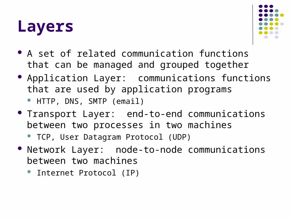
A set of related communication functions that can be managed and grouped together
Application Layer: communications functions that are used by application programs HTTP, DNS, SMTP (email)
Transport Layer: end-to-end communications between two processes in two machines TCP, User Datagram Protocol (UDP)
Network Layer: node-to-node communications between two machines Internet Protocol (IP)

Example: TCP
TCP is a transport layer protocol Provides reliable byte stream service between two
processes in two computers across the Internet Sequence numbers keep track of the bytes that have
been transmitted and received Error detection and retransmission used to recover
from transmission errors and losses TCP is connection-oriented: the sender and receiver
must first establish an association and set initial sequence numbers before data is transferred
Connection ID is specified uniquely by (send port #, send IP address, receive port #, receiver IP address)

Example: UDP
UDP is a transport layer protocol Provides best-effort datagram service
between two processes in two computers across the Internet
Port numbers distinguish various processes in the same machine
UDP is connectionless Datagram is sent immediately Quick, simple, but not reliable

Summary Layers: related communications functions
Application Layer: HTTP, DNS Transport Layer: TCP, UDP Network Layer: IP
Services: a protocol provides a communications service to the layer above TCP provides connection-oriented reliable byte transfer
service UDP provides best-effort datagram service
Each layer builds on services of lower layers HTTP builds on top of TCP DNS builds on top of UDP TCP and UDP build on top of IP
Chapter 2 Applications and
Layered Architectures
OSI Reference Model

Why Layering?
Layering simplifies design, implementation, and testing by partitioning overall communications process into parts
Protocol in each layer can be designed separately from those in other layers
Protocol makes “calls” for services from layer below Layering provides flexibility for modifying and
evolving protocols and services without having to change layers below
Monolithic non-layered architectures are costly, inflexible, and soon obsolete
Open Systems Interconnection
Network architecture: Definition of all the layers Design of protocols for every layer
By the 1970s every computer vendor had developed its own proprietary layered network architecture
Problem: computers from different vendors could not be networked together
Open Systems Interconnection (OSI) was an international effort by the International Organization for Standardization (ISO) to enable multivendor computer interconnection

OSI Reference Model
Describes a seven-layer abstract reference model for a network architecture
Purpose of the reference model was to provide a framework for the development of protocols
OSI also provided a unified view of layers, protocols, and services which is still in use in the development of new protocols
Detailed standards were developed for each layer, but most of these are not in use
TCP/IP protocols preempted deployment of OSI protocols

7-Layer OSI Reference Model
ApplicationLayer
PresentationLayer
SessionLayer
TransportLayer
NetworkLayer
Data LinkLayer
PhysicalLayer
ApplicationLayer
PresentationLayer
SessionLayer
TransportLayer
NetworkLayer
Data LinkLayer
PhysicalLayer
NetworkLayer
Application Application
Data LinkLayer
PhysicalLayer
NetworkLayer
Data LinkLayer
PhysicalLayer
Communicating End SystemsOne or More Network Nodes
End-to-End Protocols

Physical Layer
Transfers bits across link Definition & specification of the physical
aspects of a communications link Mechanical: cable, plugs, pins... Electrical/optical: modulation, signal strength,
voltage levels, bit times, … functional/procedural: how to activate, maintain, and
deactivate physical links… Ethernet, DSL, cable modem, telephone
modems… Twisted-pair cable, coaxial cable, optical fiber,
radio, infrared, …
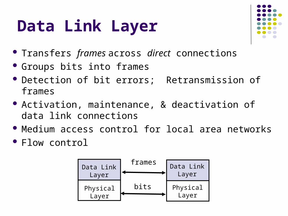
Data Link Layer
Transfers frames across direct connections Groups bits into frames Detection of bit errors; Retransmission of frames Activation, maintenance, & deactivation of data link
connections Medium access control for local area networks Flow control
Data LinkLayer
PhysicalLayer
Data LinkLayer
PhysicalLayer
frames
bits

Network Layer
Transfers packets across multiple links and/or multiple networks
Addressing must scale to large networks Nodes jointly execute routing algorithm to
determine paths across the network Forwarding transfers packet across a node Congestion control to deal with traffic surges Connection setup, maintenance, and
teardown when connection-based

Internetworking Internetworking is part of network layer and provides transfer
of packets across multiple possibly dissimilar networks Gateways (routers) direct packets across networks
G = gateway H = host
Net 1
Net 5
Net 3
Net 2
HNet 3
G
H
H
H
GG
GG
G
Net 1
Net 2 Net 4
Net 5
Ethernet LAN
ATMSwitch
ATMSwitch
ATMSwitch
ATMSwitch
ATMNetwork
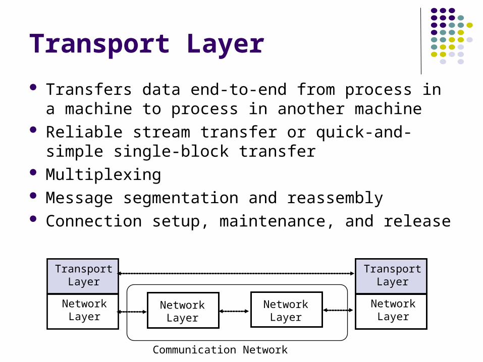
Transport Layer
Transfers data end-to-end from process in a machine to process in another machine
Reliable stream transfer or quick-and-simple single-block transfer
Multiplexing Message segmentation and reassembly Connection setup, maintenance, and release
TransportLayer
NetworkLayer
TransportLayer
NetworkLayer
NetworkLayer
NetworkLayer
Communication Network

Application & Upper Layers
Application Layer: Provides services that are frequently required by applications: DNS, web access, file transfer, email…
Presentation Layer: machine-independent representation of data…
Session Layer: dialog management, recovery from errors, …
ApplicationLayer
PresentationLayer
SessionLayer
TransportLayer
Application
ApplicationLayer
TransportLayer
Application
Incorporated into Application Layer

Headers & Trailers Each protocol uses a header that carries addresses,
sequence numbers, flag bits, length indicators, etc… CRC check bits may be appended for error detection
ApplicationLayer
TransportLayer
NetworkLayer
Data LinkLayer
PhysicalLayer
ApplicationLayer
TransportLayer
NetworkLayer
Data LinkLayer
PhysicalLayer
Application ApplicationAPP DATA
AH APP DATA
TH AH APP DATA
NH TH AH APP DATA
DH NH TH AH APP DATA CRC
bits

Summary:7-Layer OSI Reference Model
ApplicationLayer
PresentationLayer
SessionLayer
TransportLayer
NetworkLayer
Data LinkLayer
PhysicalLayer
ApplicationLayer
PresentationLayer
SessionLayer
TransportLayer
NetworkLayer
Data LinkLayer
PhysicalLayer
NetworkLayer
Application Application
Data LinkLayer
PhysicalLayer
NetworkLayer
Data LinkLayer
PhysicalLayer
One or More Network Nodes
End-to-End Protocols

Chapter 2 Applications and
Layered Architectures
TCP/IP Architecture
How the Layers Work Together

TCP/IP Protocol Suite
(ICMP, ARP)
Diverse network technologies
Reliable stream service
Userdatagram service
Distributed applications
HTTP SMTP RTP
TCP UDP
IP
Network
interface 1
Network
interface 3
Network
interface 2
DNS
Best-effort connectionless packet transfer
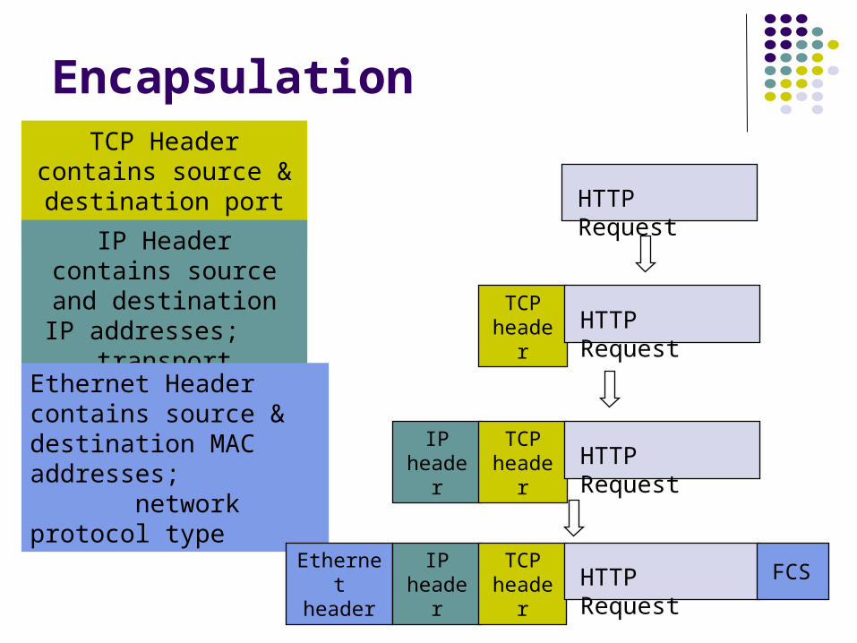
Encapsulation
TCP Header contains source & destination
port numbers
IP Header contains source and destination
IP addresses; transport protocol type
Ethernet Header contains source & destination MAC addresses; network protocol type
HTTP Request
TCP header HTTP Request
IP header
TCP header HTTP Request
Ethernet header
IP header
TCP header HTTP Request FCS
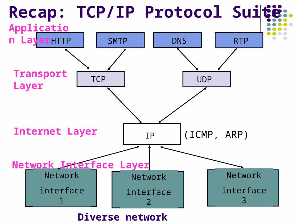
Recap: TCP/IP Protocol Suite
(ICMP, ARP)
Diverse network technologies
Transport Layer
HTTP SMTP RTP
TCP UDP
IP
Network
interface 1
Network
interface 3
Network
interface 2
DNS
Internet Layer
Application Layer
Network Interface Layer

Summary
Encapsulation is key to layering IP provides for transfer of packets across
diverse networks TCP and UDP provide universal
communications services across the Internet Distributed applications that use TCP and
UDP can operate over the entire Internet Internet names, IP addresses, port numbers,
sockets, connections, physical addresses

Error Detection and Correction

Error Control
Digital transmission systems introduce errors Applications require certain reliability level
Data applications require error-free transfer Voice & video applications tolerate some errors
Error control used when transmission system does not meet application requirement
Error control ensures a data stream is transmitted to a certain level of accuracy despite errors
Two basic approaches: Error detection & retransmission (ARQ: Automatic
Retransmission Request) Forward error correction (FEC)
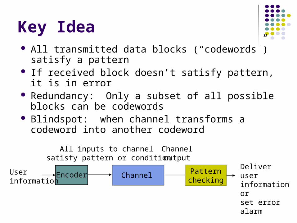
Key Idea All transmitted data blocks (“codewords”) satisfy a
pattern If received block doesn’t satisfy pattern, it is in error Redundancy: Only a subset of all possible blocks
can be codewords Blindspot: when channel transforms a codeword
into another codeword
ChannelEncoderUserinformation
Patternchecking
All inputs to channel satisfy pattern or condition
Channeloutput
Deliver user information orset error alarm
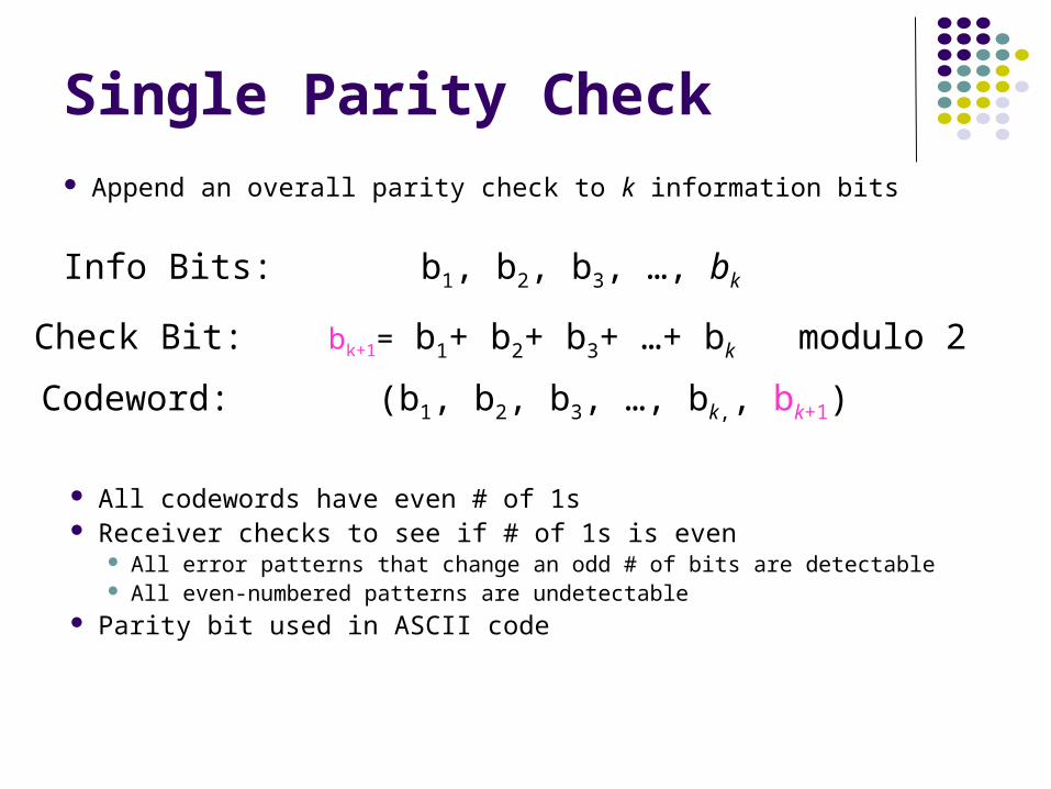
Single Parity Check
Append an overall parity check to k information bits
Info Bits: b1, b2, b3, …, bk
Check Bit: bk+1= b1+ b2+ b3+ …+ bk modulo 2
Codeword: (b1, b2, b3, …, bk,, bk+1)
All codewords have even # of 1s Receiver checks to see if # of 1s is even
All error patterns that change an odd # of bits are detectable All even-numbered patterns are undetectable
Parity bit used in ASCII code

Example of Single Parity Code
Information (7 bits): (0, 1, 0, 1, 1, 0, 0) Parity Bit: b8 = 0 + 1 +0 + 1 +1 + 0 = 1 Codeword (8 bits): (0, 1, 0, 1, 1, 0, 0, 1)
If single error in bit 3 : (0, 1, 1, 1, 1, 0, 0, 1) # of 1’s =5, odd Error detected
If errors in bits 3 and 5: (0, 1, 1, 1, 0, 0, 0, 1) # of 1’s =4, even Error not detected

Two-Dimensional Parity Check
1 0 0 1 0 0
0 1 0 0 0 1
1 0 0 1 0 0
1 1 0 1 1 0
1 0 0 1 1 1
Bottom row consists of check bit for each column
Last column consists of check bits for each row
More parity bits to improve coverage Arrange information as columns Add single parity bit to each column Add a final “parity” column Used in early error control systems

1 0 0 1 0 0
0 0 0 1 0 1
1 0 0 1 0 0
1 0 0 0 1 0
1 0 0 1 1 1
1 0 0 1 0 0
0 0 0 0 0 1
1 0 0 1 0 0
1 0 0 1 1 0
1 0 0 1 1 1
1 0 0 1 0 0
0 0 0 1 0 1
1 0 0 1 0 0
1 0 0 1 1 0
1 0 0 1 1 1
1 0 0 1 0 0
0 0 0 0 0 1
1 0 0 1 0 0
1 1 0 1 1 0
1 0 0 1 1 1
Arrows indicate failed check bits
Two errorsOne error
Three errors Four errors
(undetectable)
Error-detecting capability
1, 2, or 3 errors can always be
detected; Not all patterns >4 errors can be detected

Other Error Detection Codes
Many applications require very low error rate Need codes that detect the vast majority of errors Single parity check codes do not detect enough
errors Two-dimensional codes require too many check bits The following error detecting codes used in practice:
CRC Polynomial Codes
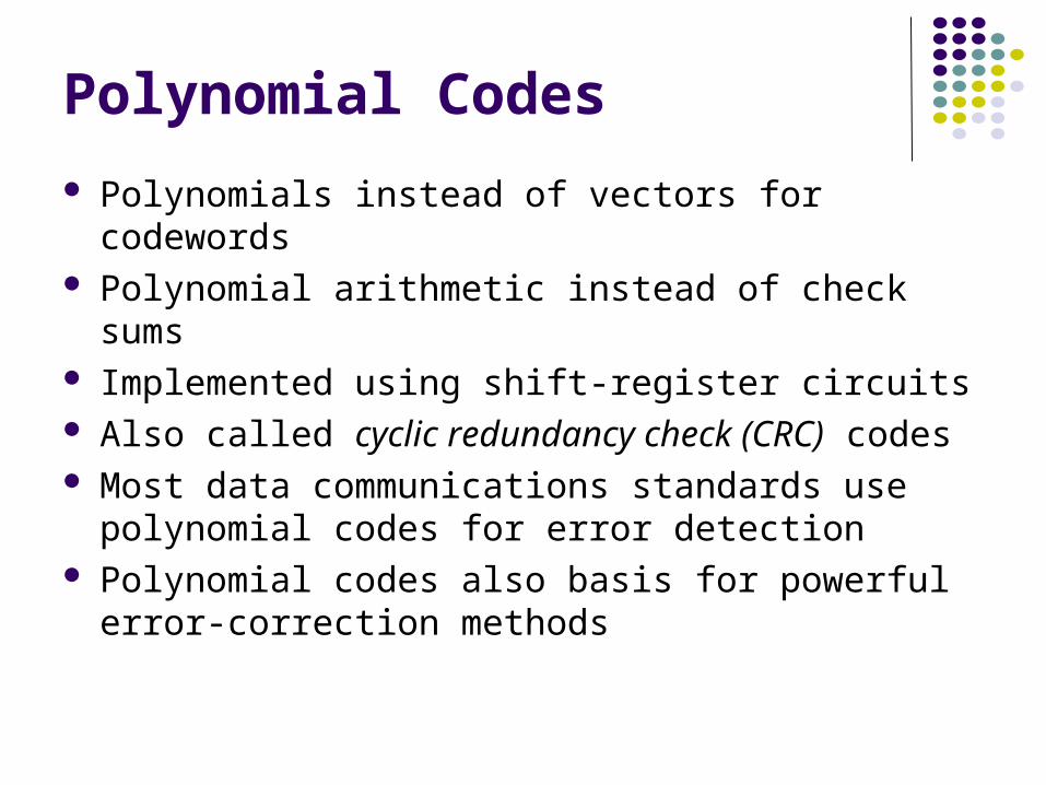
Polynomial Codes
Polynomials instead of vectors for codewords Polynomial arithmetic instead of check sums Implemented using shift-register circuits Also called cyclic redundancy check (CRC) codes Most data communications standards use
polynomial codes for error detection Polynomial codes also basis for powerful error-
correction methods
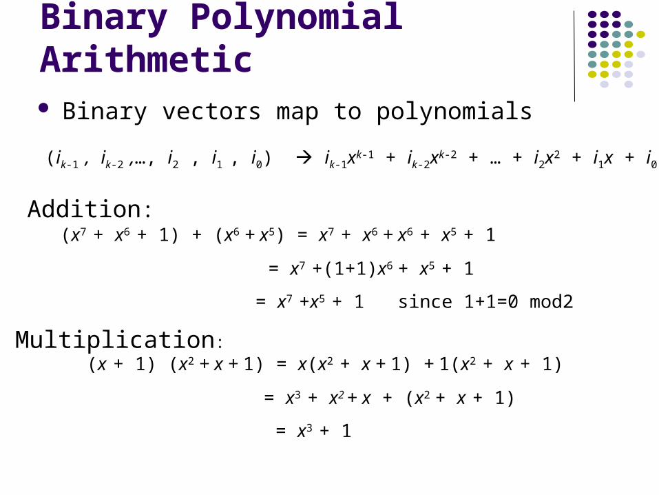
Addition:
Multiplication:
Binary Polynomial Arithmetic Binary vectors map to polynomials
(ik-1 , ik-2 ,…, i2 , i1 , i0) ik-1xk-1 + ik-2xk-2 + … + i2x2 + i1x + i0
(x7 + x6 + 1) + (x6 + x5) = x7 + x6 + x6 + x5 + 1
= x7 +(1+1)x6 + x5 + 1
= x7 +x5 + 1 since 1+1=0 mod2
(x + 1) (x2 + x + 1) = x(x2 + x + 1) + 1(x2 + x + 1)
= x3 + x2 + x + (x2 + x + 1)
= x3 + 1

Binary Polynomial Division Division with Decimal Numbers
32
35 ) 12223
10517 2
4
140divisor
quotient
remainder
dividend1222 = 34 x 35 + 32
dividend = quotient x divisor +remainder
Polynomial Divisionx3 + x + 1 ) x6 + x5
x6 + x4 + x3
x5 + x4 + x3
x5 + x3 + x2
x4 + x2
x4 + x2 + x
x
= q(x) quotient
= r(x) remainder
divisordividend
+ x+ x2x3
Note: Degree of r(x) is less than degree of divisor

Polynomial Coding Code has binary generator polynomial of degree n–k
k information bits define polynomial of degree k – 1
Find remainder polynomial of at most degree n – k – 1
g(x) ) xn-k i(x)
q(x)
r(x)xn-ki(x) = q(x)g(x) + r(x)
Define the codeword polynomial of degree n – 1
b(x) = xn-ki(x) + r(x)
n bits k bits n-k bits
g(x) = xn-k + gn-k-1xn-k-1 + … + g2x2 + g1x + 1
i(x) = ik-1xk-1 + ik-2xk-2 + … + i2x2 + i1x + i0
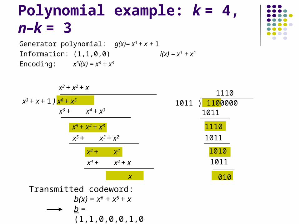
Transmitted codeword:b(x) = x6 + x5 + xb = (1,1,0,0,0,1,0)
1011 ) 1100000
1110
1011
1110
1011
10101011
010
x3 + x + 1 ) x6 + x5
x3 + x2 + x
x6 + x4 + x3
x5 + x4 + x3
x5 + x3 + x2
x4 + x2
x4 + x2 + x
x
Polynomial example: k = 4, n–k = 3Generator polynomial: g(x)= x3 + x + 1
Information: (1,1,0,0) i(x) = x3 + x2
Encoding: x3i(x) = x6 + x5

The Pattern in Polynomial Coding
All codewords satisfy the following pattern:
All codewords are a multiple of g(x)! Receiver should divide received n-tuple by g(x) and check if remainder is zero If remainder is nonzero, then received n-tuple is not a codeword
b(x) = xn-ki(x) + r(x) = q(x)g(x) + r(x) + r(x) = q(x)g(x)
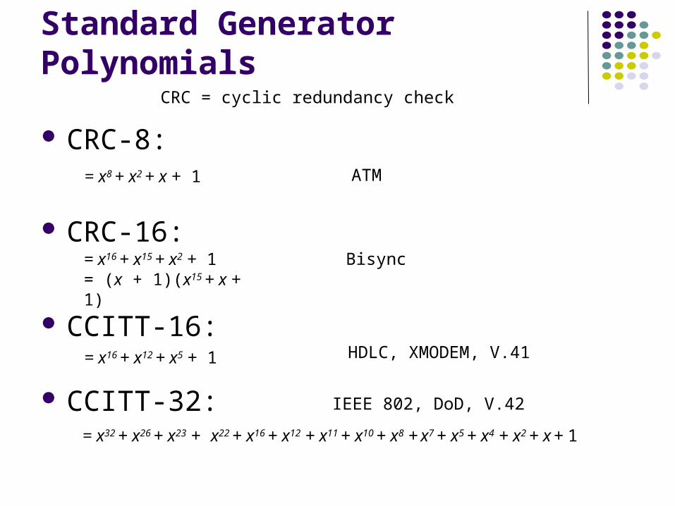
Standard Generator Polynomials
CRC-8:
CRC-16:
CCITT-16:
CCITT-32:
CRC = cyclic redundancy check
HDLC, XMODEM, V.41
IEEE 802, DoD, V.42
Bisync
ATM
= x8 + x2 + x + 1
= x16 + x15 + x2 + 1= (x + 1)(x15 + x + 1)
= x16 + x12 + x5 + 1
= x32 + x26 + x23 + x22 + x16 + x12 + x11 + x10 + x8 + x7 + x5 + x4 + x2 + x + 1


