

OZONE APPLICATION NOTE #3
OZONE SETTING
www.efore.com Page 1 AN3_Ozone Setting rev06_May2017
INTRODUCTION
Ozone LED Driver stands for an extremely flexible LED Driver, Designed for fast and easy configuration. This Application Note “AN3_Ozone Setting” illustrates the setting options of the Ozone LED driver in order to allow a fast and easy setting, performed by the lamp manufacturer and /or installer. An external dedicated and portable programming tool (available as optional, ordering code: RSOZ070-PTOOL), permits to customize different Ozone LED driver key parameters. This guarantees extreme flexibility during final products (lamps) production process, because all OEMs will be able to directly personalize their products during the production process, avoiding managing different LED driver models and their stocking inventory. In addition to the several benefits that this feature allows during the production process, it permits also to operate directly in the lamp installation field, avoiding wasting of time due to product’s replacement.
OZONE PROGRAMMING TOOL
The battery powered unit (see Figure 1), is a user friendly remote programmer that permits the user to manage the following settings:
Output Constant Current Setting
Light Fade Time Setting
DALI communication enabling/disabling
PWM dimming enabling/disabling
Output current shape Constant Amplitude or PWM
Figure 1: Ozone Programming Tool (Code RSOZ070-PTOOL)
4-position Dip Switch for Fade Time setting and Dimming Option setting.
10-position rotary switches for Output Current Setting.
“Save” push button for setting confirmation.
Feedback LEDs
OZONE APPLICATION NOTE #3
OZONE SETTING
www.efore.com Page 2 AN3_Ozone Setting rev06_May2017
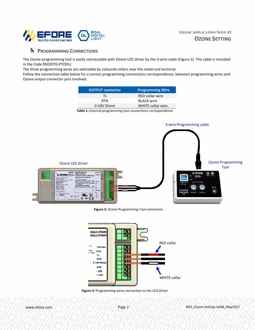
PROGRAMMING CONNECTIONS
The Ozone programming tool is easily connectable with Ozone LED driver by the 3-wire cable (Figure 2). The cable is included in the Code RSOZ070-PTOOL) The three programming wires are selectable by coloured collars near the metal end terminal. Follow the connection table below for a correct programming connections correspondence, between programming wires and Ozone output connector pins involved.
OUTPUT connector Programming Wire
Ts RED collar wire RTN BLACK wire
0-10V Dimm WHITE collar wire Table 1: External programming tool connections correspondence
Figure 2: Ozone Programming Tool connection
Figure 3: Programming wires connection to the LED Driver
3-wire Programming cable
Ozone Programming Tool
Ozone LED driver
RED collar
WHITE collar
OZONE APPLICATION NOTE #3
OZONE SETTING
www.efore.com Page 3 AN3_Ozone Setting rev06_May2017
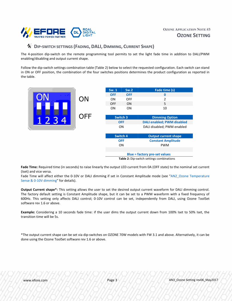
DIP-SWITCH SETTINGS (FADING, DALI, DIMMING, CURRENT SHAPE)
The 4-position dip-switch on the remote programming tool permits to set the light fade time in addition to DALI/PWM enabling/disabling and output current shape. Follow the dip-switch settings combination table (Table 2) below to select the requested configuration. Each switch can stand in ON or OFF position, the combination of the four switches positions determines the product configuration as reported in the table. Fade Time: Required time (in seconds) to raise linearly the output LED current from 0A (OFF state) to the nominal set current (Iset) and vice versa. Fade Time will affect either the 0-10V or DALI dimming if set in Constant Amplitude mode (see “AN2_Ozone Temperature Sense & 0-10V dimming” for details). Output Current shape*: This setting allows the user to set the desired output current waveform for DALI dimming control. The factory default setting is Constant Amplitude shape, but it can be set to a PWM waveform with a fixed frequency of 600Hz. This setting only affects DALI control; 0-10V control can be set, independently from DALI, using Ozone ToolSet software rev 1.6 or above. Example: Considering a 10 seconds fade time: if the user dims the output current down from 100% Iset to 50% Iset, the transition time will be 5s. *The output current shape can be set via dip-switches on OZONE 70W models with FW 3.1 and above. Alternatively, it can be done using the Ozone ToolSet software rev 1.6 or above.
Sw. 1 Sw.2 Fade time (s)
OFF OFF 0 ON OFF 2 OFF ON 5 ON ON 10
Switch 3 Dimming Option
OFF DALI enabled; PWM disabled
ON DALI disabled; PWM enabled
Switch 4 Output current shape OFF Constant Amplitude ON PWM
Blue = factory pre-set values
Table 2: Dip-switch settings combinations
ON
OFF

OZONE APPLICATION NOTE #3
OZONE SETTING
www.efore.com Page 4 AN3_Ozone Setting rev06_May2017
ROTARY SWITCHES SETTINGS (OUTPUT CURRENT)
By combining the two 10-way rotary switches positions, it is possible to set the output constant current value. A very wide output current range of values, from 350mA to 2100mA, can be selected in 50mA steps, for a 70W total maximum output power. See the table below to select the right rotary switches positions corresponding to the required output current. Output Current
Set RSOZ070-35 RSOZ070-60 RSOZ070-120 RSOZ070-200
ISET Rotary Position Vout Min10
Vout Max10
Vout Min10
Vout Max10
Vout Min10
Vout Max10
Vout Min10
Vout Max10
mA R1 - R2 VDC VDC VDC VDC VDC VDC VDC VDC 3509 0-0 30 56 60 115 120 195 400 0-1 30 56 60 115 120 175 450 0-2 30 56 60 115 120 155.6 500 0-3 30 56 60 115 120 140 550 0-4 30 56 60 115 120 127.3 6009 0-5 30 56 60 115 650 0-6 30 56 60 107.7 700 0-7 30 56 60 100 750 0-8 30 56 60 93.3 800 0-9 30 56 60 87.5 850 1-0 30 56 60 82.4 900 1-1 30 56 60 77.8 950 1-2 30 56 60 73.7
1000 1-3 20 33 30 56 60 70.0 1050 1-4 20 33 30 56 60 66.7 1100 1-5 20 33 30 56 60 63.6 1150 1-6 20 33 30 56
Note 9: Ozone 70W LED Drivers are factory pre-set to have the maximum output power in the widest Output Voltage Range.
ISET =2100mA for RSOZ070-35 ISET =1250mA for RSOZ070-60 ISET =600mA for RSOZ070-120 ISET =350mA for RSOZ070-200.
Note 10: Care should be taken during the design phase to assure the alignment between the Total Forward Voltage of the LED string (Vf total) when the Output is not dimmed and the LED Driver Output Voltage Range (Vout min, Vout max). The value (VF total @ NO dimming) has to be within the Output Voltage Range (Vout min, Vout max), considering also Vf modifications due to thermal effects and Vf tolerance.
Please note that when dimming is present the Driver works also below its Vout min. In the conditions marked with (*) the Driver is still within the spec. but consider that they are difficult to maintain by the LED string due to the Vf variation caused by thermal effects and VF tolerance.
1200 1-7 20 33 30 56 12509 1-8 20 33 30 56 1300 1-9 20 33 30 53.8 1350 2-0 20 33 30 51.9 1400 2-1 20 33 30 50.0 1450 2-2 20 33 30 48.3 1500 2-3 20 33 30 46.7 1550 2-4 20 33 30 45.2 1600 2-5 20 33 30 43.8 1650 2-6 20 33 30 42.4 1700 2-7 20 33 30 41.2 1750 2-8 20 33 30 40.0 1800 2-9 20 33 30 38.9 1850 3-0 20 33 30 37.8 1900 3-1 20 33 30 36.8 1950 3-2 20 33 30 35.9 2000 3-3 20 33 30 35.0 2050 3-4 20 33 30 34.1* 21009 3-5 20 33 30 33.3* 2150 3-6 20 32.6 2200 3-7 20 31.8 2250 3-8 20 31.1 2300 3-9 20 30.4 2350 4-0 20 29.8 2400 4-1 20 29.2 2450 4-2 20 28.6 2500 4-3 20 28.0 2550 4-4 20 27.5 2600 4-5 20 26.9

OZONE APPLICATION NOTE #3
OZONE SETTING
www.efore.com Page 5 AN3_Ozone Setting rev06_May2017
PROGRAMMING OPERATIONS SEQUENCE
Run the following 10-step sequence for Ozone LED driver programming, using the “RSOZ070-PTOOL” external programming tool.
1. If connected, unplug AC power from the Ozone input AC connector. 2. If connected, unplug all wires from the secondary connectors (DALI, LED board, +5Vaux, Ts). 3. Connect the 3-wire cable of the external programming tool to the Ozone output connector, as shown in Figure 2 and
3. 4. Reconnect the AC power to the Ozone input AC connector. 5. Select and run the correct Dip-switch settings combinations according to Table 2. 6. Choose the output Constant Current value and place the correspondent rotary switches positions, according to Table
3. 7. Press “Save” push button. 8. Verify the feedback green LED blinks (2 fast blinks followed by 1 longer blink). 9. Verify that the error red LED remains OFF after the green LED blinking. 10. First disconnect the AC cable and then the 3-wire programming cable from the Ozone output connector.
Now the new settings are installed and they will be active at the next Ozone power-on.
OZONE TOOLSET SOFTWARE
The Ozone microcontroller based technology permits to implement additional features that have a main rule especially in outdoor lighting applications. The optional programmable functions are:
1. Driver general hardware settings (PWM, DALI, current settings) 2. Adjustable Dimmer function 3. Constant Light function
These features can be programmed and stored in the Ozone Programming Tool by connecting it to a laptop with a USB cable, and using the dedicated Ozone Toolset Software (provided with the Ozone Programming Tool). See “UM1_Ozone Toolset Software Manual” for further details.
WARNINGS:
If the error red LED turns-on after the two green LED fast blinks, it means that the programming operation failed. In this case, repeat the programming sequence from the beginning paying particular attention to wires connections and rotary switches combination.
Any rotary switches combination not shown in Table 3 must be considered as not allowed.
Additional red LED fast blinks after the programming phase, indicate a low battery level.
OZONE APPLICATION NOTE #3
OZONE SETTING
www.efore.com Page 6 AN3_Ozone Setting rev06_May2017
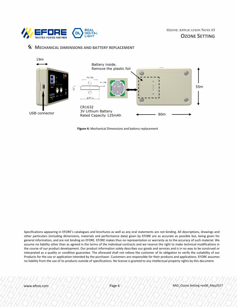
MECHANICAL DIMENSIONS AND BATTERY REPLACEMENT
Figure 4: Mechanical Dimensions and battery replacement
CR1632 3V Lithium Battery Rated Capacity 125mAh
USB connector 80mm
55mm
19mm Battery inside.
Remove the plastic foil
Specifications appearing in EFORE’s catalogues and brochures as well as any oral statements are not binding. All descriptions, drawings and other particulars (including dimensions, materials and performance data) given by EFORE are as accurate as possible but, being given for general information, and are not binding on EFORE. EFORE makes thus no representation or warranty as to the accuracy of such material. We assume no liability other than as agreed in the terms of the individual contracts and we reserve the right to make technical modifications in the course of our product development. Our product information solely describes our goods and services and is in no way to be construed or interpreted as a quality or condition guarantee. The aforesaid shall not relieve the customer of its obligation to verify the suitability of our Products for the use or application intended by the purchaser. Customers are responsible for their products and applications. EFORE assumes no liability from the use of its products outside of specifications. No license is granted to any intellectual property rights by this document.


