

QUICK START GUIDEiridium PotsDOCK 9555
Suitable for the Iridium 9555 Portable Satellite Telephone
Beam Communications Pty Ltd
6. Using PotsDOCK 9555• AfterapplyingpowertoACpoweradaptororturningkey/Accon,the
PotsDOCKwillbeepuponpowerup
• Waitforphonetopowerupandregister
PANEL BUTTONS AND INDICATORS:
LOCATION BUTTON MODE LED/SOUNDOutofCall:ToggleRingerMode
LEDoff.Ringerchoicesoundsaspreview.
DuringIn-CallRJ11orBluetooth:Mute(singlepress)
LEDisREDwhenMUTE.
DuringIn-CallRJ11orBluetooth:Earpiece-jack(1.5secondspress)
Subsequentsinglepress,exitsEarpiece-jack
LEDflashesORANGE.
Bluetooth®On(singlepress)
Bluetooth®OFF(1.5secondspress)
LEDisBLUE(halfintensity)whenBluetooth®ONandispaired.Fastflashingwhensearchingdevice.Slowflashingduringacall.
SinglebeepsoundswhenturningOFF.
DiscoveryMode(5secondspress)
LEDflashesORANGEandBLUE.
Ringersoundsdouble(2)beeps.ClearBluetooth®Devices(10secondspress)
Ringersoundstriple(3)beeps.
SendTrackingMessage(singlepress)
LEDoperatesaccordingtosettingsinPDMS.BeepisalsoconfigurableaccordingtoPDMS
ClearAlertMode(7secondspress)
LEDturnsGREEN–re-armed&GPSFixready.SingleBeepsounds.
IfLEDisFlashingGREEN–NoGPSFix,orNoIridiumSignal
LEDisOFFwhenAlert/Trackingisdisabled.
+
ActivateAlertMode
(2secondspress,BOTHbuttonstogether)
TrackLEDturnsREDwhenAlert Triggeredandsinglebeepsounds.
TrackLEDFlashingREDwhenAlert Message sent
TrackLEDflashingORANGEwhenAlert is acknowledged
4. OptionsTracking & Alert:Tracking & Alert requires GPS antenna, and setup of the tracking and/or alerting messages. Please refer to the PDMS Application (PotsDOCK ManagementSystem)toenableandconfigureTracking&Alert.
External Alert Button:Connect Normally-CLOSED button, to the BrownandGreenwires(itcanbeextendedforlongerruns).TheloopneedstobeOPEN(eg.pressingbutton)for2secondstoactivateAlertstate.
Privacy Handset:1. ThePrivacyHandsetKitisorderedseparately.2. Mountthehandsetcuptothemountingplate.3. Mount the spacer plate and the mounting
bracket, by using the longer screws providedwiththekit.(Re-installedtheRAMarm-bracketbehindtheseplates).
4. ConnectthePrivacyHandset3.5mmplugintotherearcablejack.
5. PrivacyHandsetmode isactivewhenever thehandsetisremovedfromthecup.
Earpiece-Jack Mode:Usea2.5mmearpiecepluggedintotherightsideofthe9555handset.1. DuringaRJ11orBluetoothcall,toenableEarpiece-JackMode,pressand
holdtheMutebuttonfor1.5seconds.TheLEDflashesOrange.2. ToexitEarpiece-JackModeandreverttoRJ11orBluetooth,presstheMute
buttononce.
TEL: +61 3 8588 4500 FAX: +61 3 9560 9055
GPS
ALERT
TRACKING
RJ11/PBX
BLUETOOTH
USBDATA
USRQSG0047012
5. Add Bluetooth Device (optional)AUDIO:Toconfigure(pair)toaBluetooth®headsetdevice:
1. DiscoveryMode:Press and hold for 5 secstheBluetooth®buttononthecradleTheLEDflashesBlueandOrange.
2. HoldtheHeadsetdevicebutton(s)toenterpairingmode.3. Oncepaired,theBluetooth®LEDisBlue(halfintensity).4. Bluetooth®canbeturnedONwithasingle press,andOFFbypress for
2 secstheBluetooth®buttononthecradle.
DATA:Toconfigure(pair)toaBluetooth®serialdatadevice:
1. TurnOFFanyotherBluetoothAudioorDatadevicesinrangenearby.2. DiscoveryMode:Press and hold for 5 secstheBluetooth®buttonon
thecradleTheLEDflashesBlueandOrange.3. Putthedata-device/computerintoDiscoverymode.4. Oncepaired,theBluetooth®LEDwillstartslowflashingBlue.
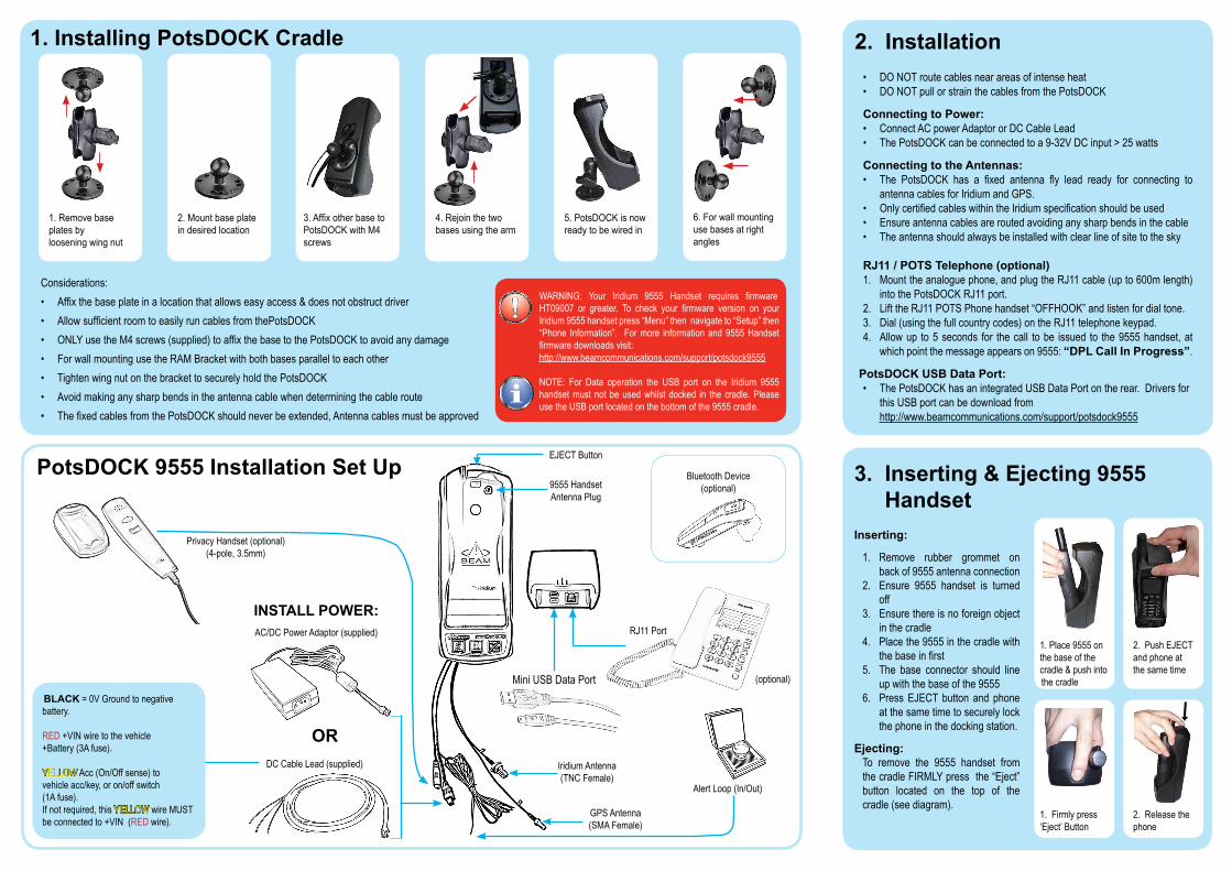
1. Installing PotsDOCK Cradle
3.AffixotherbasetoPotsDOCKwithM4screws
5.PotsDOCKisnowreadytobewiredin
2.Mountbaseplateindesiredlocation
1.Removebaseplatesbylooseningwingnut
Considerations:• Affixthebaseplateinalocationthatallowseasyaccess&doesnotobstructdriver• AllowsufficientroomtoeasilyruncablesfromthePotsDOCK• ONLYusetheM4screws(supplied)toaffixthebasetothePotsDOCKtoavoidanydamage• ForwallmountingusetheRAMBracketwithbothbasesparalleltoeachother• TightenwingnutonthebrackettosecurelyholdthePotsDOCK• Avoidmakinganysharpbendsintheantennacablewhendeterminingthecableroute• ThefixedcablesfromthePotsDOCKshouldneverbeextended,Antennacablesmustbeapproved
2. Installation• DONOTroutecablesnearareasofintenseheat• DONOTpullorstrainthecablesfromthePotsDOCK
Connecting to Power:• ConnectACpowerAdaptororDCCableLead• ThePotsDOCKcanbeconnectedtoa9-32VDCinput>25watts
Connecting to the Antennas:• The PotsDOCK has a fixed antenna fly lead ready for connecting to
antennacablesforIridiumandGPS.• OnlycertifiedcableswithintheIridiumspecificationshouldbeused• Ensureantennacablesareroutedavoidinganysharpbendsinthecable• Theantennashouldalwaysbeinstalledwithclearlineofsitetothesky
RJ11 / POTS Telephone (optional)1. Mounttheanaloguephone,andplugtheRJ11cable(upto600mlength)
intothePotsDOCKRJ11port.2. LifttheRJ11POTSPhonehandset“OFFHOOK”andlistenfordialtone.3. Dial(usingthefullcountrycodes)ontheRJ11telephonekeypad.4. Allowup to5seconds for thecall tobe issued to the9555handset,at
whichpointthemessageappearson9555:“DPL Call In Progress”.
PotsDOCK USB Data Port:• ThePotsDOCKhasanintegratedUSBDataPortontherear.Driversfor
thisUSBportcanbedownloadfromhttp://www.beamcommunications.com/support/potsdock9555
PotsDOCK 9555 Installation Set Up
6.Forwallmountingusebasesatrightangles
4.Rejointhetwobasesusingthearm
WARNING: Your Iridium 9555 Handset requires firmwareHT09007 or greater. To check your firmware version on yourIridium9555handsetpress“Menu”thennavigateto“Setup”then“Phone Information”. Formore information and9555Handsetfirmwaredownloadsvisit:http://www.beamcommunications.com/support/potsdock9555
NOTE: For Data operation the USB port on the Iridium 9555handsetmust not beusedwhilst docked in the cradle.PleaseusetheUSBportlocatedonthebottomofthe9555cradle.
AC/DCPowerAdaptor(supplied)
DCCableLead(supplied)
INSTALL POWER:
BluetoothDevice(optional)
BLACK=0VGroundtonegativebattery.
RED+VINwiretothevehicle+Battery(3Afuse).
YELLOWAcc(On/Offsense)tovehicleacc/key,oron/offswitch(1Afuse).Ifnotrequired,thisYELLOWwireMUSTbeconnectedto+VIN(REDwire).
OR
PrivacyHandset(optional)(4-pole,3.5mm)
EJECTButton
9555HandsetAntennaPlug
RJ11Port
MiniUSBDataPort
IridiumAntenna(TNCFemale)
GPSAntenna(SMAFemale)
AlertLoop(In/Out)
(optional)
3. Inserting & Ejecting 9555 HandsetInserting:
1. Remove rubber grommet onbackof9555antennaconnection
2. Ensure 9555 handset is turnedoff
3. Ensurethereisnoforeignobjectinthecradle
4. Placethe9555inthecradlewiththebaseinfirst
5. The base connector should lineupwiththebaseofthe9555
6. PressEJECTbutton and phoneatthesametimetosecurelylockthephoneinthedockingstation.
Ejecting:To remove the 9555 handset fromthecradleFIRMLYpressthe“Eject”button located on the top of the cradle(seediagram).
2.PushEJECTandphoneatthesametime
1.Place9555onthebaseofthecradle&pushintothecradle
1.Firmlypress‘Eject’Button
2.Releasethephone


